GPS Network Time Server on Raspberry Pi: GpsNtp-Pi ... Papers/Reeve_GpsNtp-Pi.pdf · GPS Network...
13
See last page for copyright and document info, File: Reeve_GpsNtp-Pi.doc, Page 1 GPS Network Time Server on Raspberry Pi: GpsNtp-Pi Whitham D. Reeve 1. Introduction This article describes an application of the Raspberry Pi, or RPi, as a network time server. A network time server determines the time from an accurate reference clock and distributes this time to clients on a local area network (LAN) or a wide area network (WAN) such as the internet. The clients typically are ordinary PCs used in radio astronomy observations. The RPi hardware and software is combined with the Network Time Protocol and a Global Navigation Satellite System receiver to produce a high performance device. In the following sections I provide descriptions of the protocols, reference clocks and hardware requirements as well as statistical analyses of two RPi network time server systems. A companion document, GpsNtp-Pi Time Server Installation and Operation Guide {GpsNtp-Pi}, provides detailed setup instructions. AC Power Adapter Local Area Network Ethernet Power Internet NTP Server using Raspberry Pi Model B+ Internet Router NTP Client 5V Optional WLAN GNSS Receiver PPS NMEA 3.3 V External NTP Servers NTP Client NTP Client GNSS Satellite External NTP Servers Figure 1 ~ GpsNtp-Pi time server block diagram. The server’s main functional components are the Raspberry Pi platform and GNSS (or GPS) receiver on the left. The time server can be provisioned and used through a wired or wireless network connection and can serve time to clients on the LAN or WAN. It also can work with external time servers. The Global Navigation Satellite System, or GNSS, is most often simply called GPS after the original Global Positioning System deployed by the US government; however, GNSS includes navigation satellites and systems by other countries. By their very nature these systems provide very high time accuracy to receivers, which can then produce reference clocks for a network time server. The Network Time Protocol, or NTP, is the most Abbreviations: GNSS; Global Navigation Satellite System GPIO: General Purpose Input-Output GPS: Global Positioning System GPSD: GPS Daemon LAN: Local Area Network NMEA: National Marine Electronics Association NTP: Network Time Protocol NTPD: NTP Daemon PC: Personal Computer PPS: Pulse Per Second RPi: Raspberry Pi USD: US Dollar UT: Universal Time UTC: Coordinated Universal Time WAN: Wide Area Network WLAN: Wireless LAN Note: Internet links in braces { } and references in brackets [ ] are provided in section 9.
Transcript of GPS Network Time Server on Raspberry Pi: GpsNtp-Pi ... Papers/Reeve_GpsNtp-Pi.pdf · GPS Network...

See last page for copyright and document info, File: Reeve_GpsNtp-Pi.doc, Page 1
GPS Network Time Server on Raspberry Pi: GpsNtp-PiWhitham D. Reeve
1. Introduction
This article describes an application of the Raspberry Pi, or RPi, as a
network time server. A network time server determines the time from an
accurate reference clock and distributes this time to clients on a local
area network (LAN) or a wide area network (WAN) such as the internet.
The clients typically are ordinary PCs used in radio astronomy
observations.
The RPi hardware and software is combined with the Network Time Protocol and a Global Navigation Satellite
System receiver to produce a high performance device. In the following sections I provide descriptions of the
protocols, reference clocks and hardware requirements as well as statistical
analyses of two RPi network time server systems. A companion document,
GpsNtp-Pi Time Server Installation and Operation Guide {GpsNtp-Pi}, provides
detailed setup instructions.
AC PowerAdapter
Local AreaNetwork
Ethernet
Power
Internet
NTP Server usingRaspberry Pi
Model B+
InternetRouter
NTPClient
5 V
OptionalWLAN
GNSS Receiver
PPSNMEA3.3 V
ExternalNTP
Servers
NTPClient
NTPClient
GNSSSatellite
ExternalNTP
Servers
Figure 1 ~ GpsNtp-Pi time server block diagram. The server’s main functional components are the Raspberry Pi platform andGNSS (or GPS) receiver on the left. The time server can be provisioned and used through a wired or wireless networkconnection and can serve time to clients on the LAN or WAN. It also can work with external time servers.
The Global Navigation Satellite System, or GNSS, is most often simply called GPS after the original Global
Positioning System deployed by the US government; however, GNSS includes navigation satellites and systems
by other countries. By their very nature these systems provide very high time accuracy to receivers, which can
then produce reference clocks for a network time server. The Network Time Protocol, or NTP, is the most
Abbreviations:GNSS; Global Navigation Satellite SystemGPIO: General Purpose Input-OutputGPS: Global Positioning SystemGPSD: GPS DaemonLAN: Local Area NetworkNMEA: National Marine ElectronicsAssociationNTP: Network Time ProtocolNTPD: NTP DaemonPC: Personal ComputerPPS: Pulse Per SecondRPi: Raspberry PiUSD: US DollarUT: Universal TimeUTC: Coordinated Universal TimeWAN: Wide Area NetworkWLAN: Wireless LAN
Note: Internet links in braces { }and references in brackets [ ] areprovided in section 9.

See last page for copyright and document info, File: Reeve_GpsNtp-Pi.doc, Page 2
common protocol for exchanging time information over a network. It is used to synchronize and accurately
maintain time-of-day clocks in PCs and larger computer systems (figure 1).
As described here, the GpsNtp-Pi network time server total cost is about 100 USD. This system can operate as a
standalone NTP time server. Standalone in this context means the GpsNtp-Pi has no connection to any other
NTP server; it is not an autonomous time server because it relies on reception of GNSS signals. The GpsNtp-Pi
also can be used in conjunction with other local NTP servers or a pool of remote NTP servers to improve overall
performance and reliability (the remote NTP servers do not have to be based on RPi technology). The system
meets the needs of many radio astronomy applications where there is the need for accurate time stamps on
radio observations produced on a PC. In the GNSS and NTP environments, all times are in Coordinated Universal
Time (UTC). The GpsNtp-Pi does not have a holdover clock, so a failure of the GPS receiver or loss of satellite
reception results in time server failure.
I claim no originality for the concept of combining the Raspberry Pi with a GPS receiver. However, I have
introduced a number of enhancements compared to the NTP server projects described on internet websites. In
particular, the standalone operation described here is not described in any useful detail anywhere else. Also, I
have provided specific installation and provisioning details that I had to determine through considerable
research, lengthy testing and trial and error. Many NTP server projects found online perpetuate provisioning
mistakes and errors from other projects, and some online information and setups are just plain wrong. The
project described here corrects those mistakes or avoids them altogether.
This project follows two of my previous RPi projects, LWA TV {LWATV) and Callisto-Pi (ReeveCPi). RPi hardware
descriptions as well as brief overviews are given there.
2. Network Time Protocol
Network Time Protocol is a set of procedures used by computers and PCs to exchange time
information and then to compensate for the relative inaccuracy of a PC’s real-time (or time-of-
day) clock. NTP is run as a background process or daemon. The underlying software is called
NTP daemon or just NTPD. The software currently is version 4 (NTPv4), and it as well as
tutorials and configuration information can be downloaded from the NTP website {NTPOrg}.
NTPD can operate as a time client or server, and it always uses Coordinated Universal Time (UTC). When
installed as a client on a PC it synchronizes and regulates the PC clock by periodically obtaining time information
from an external NTP server, either on the same LAN or over the internet (WAN). NTP can use a reference clock,
which is a clock that obtains accurate time information from an external source such as a GPS receiver or atomic
clock. NTP cannot operate on a client PC unless it has at least one source of time information, either a reference
clock or the URL or IP address of an NTP server. Most PCs operate as NTP clients, typically by running a free
software application such as SymmTime, Dimension4 or Meinberg NTP. Many other clients will be revealed by
an internet search.
There may be considerable variability in the networks between NTP clients and servers, leading to variable
delays in synchronization messages between a network time server and a client PC. NTPD’s job is to monitor

See last page for copyright and document info, File: Reeve_GpsNtp-Pi.doc, Page 3
these delays in real time and then estimate what synchronization actions are needed at the client to reduce the
difference between the PC’s clock time and the NTP server’s clock time. NTPD speeds up or slows down the PC’s
clock until synchronization is achieved.
NTPD has an ultimate precision of about 200 ps but PCs and most other computer systems cannot measure time
to this resolution. Generally, after the PC’s clock is set, NTPD will maintain it within 128 ms even in the face of
extreme network path congestion and jitter. NTPD slews the client’s clock in very small steps, effectively
providing a continuous timescale. The maximum slew rate under most conditions is limited to 500 parts per
million. A simple calculation shows that the maximum slew rate is 2000 s for each 1 s error.
An overall goal of using NTP on a PC is to maintain the clock offset from UTC to ≤ 100 ms. This means that the
polling and correction interval by the PC’s NTP client cannot be too long. For example, if the PC’s clock drifts 250
ms/h (equivalent to 6 s/day) and the NTP polling interval is 24 h, the goal never will be achieved. Windows PCs
that have the built-in Internet Time feature enabled use a 7 day update interval by default, much too long to be
of any use in radio observations. On the other hand, a polling interval that is too short usually serves no useful
purpose, increasing network load and potentially manifesting as clock instability.
I have found that the best interval is between 15 min and 2 h for most PCs. Generally, the shorter interval is
used on PCs subject to considerable short-term temperature variations and longer interval for PCs in stable
environments. It should be noted that PCs running many CPU-intensive processes throughout the day will
experience higher internal temperature variations and thus larger clock variations even though they may be in a
stable ambient environment.
The NTPD handles leap seconds very easily and procedures are included in the installation guide so that it
automatically implements a leap second when the time comes. A leap second is added or subtracted every so
often to keep Universal Time (UT, in particular, UT1) and Coordinated Universal Time (UTC) synchronized within
less than ±0.9 second. The UT time scale is based on Earth’s rotation rate. Embedded in UT is the mean
astronomical second, which is defined as 1/86 400 of the mean solar day as determined by precise
measurements.
On the other hand, UTC is an atomic time scale based on the emissions frequency of cesium atoms when certain
electrons change state. Embedded in UTC is the definition of the second, which is 9 192 631 770 periods (a
frequency of about 9.193 GHz) of the radiation emitted from cesium 133 when it is in a specific environment. As
of this writing (February 2015), the most recent leap second was added at the end of June 2012 and another one
is scheduled to be added at end of June 2015 (see {RvTime}).
3. Time Sources and Reference Clocks
In the NTP server described here, two reference clocks are used, both obtained from the GPS receiver.
The first is a series of pulses on one of the receiver output pins. These pulses very accurately indicate
the start of a UTC second and are called pulse-per-second or PPS. The PPS signal is a simple pulse train
(figure 2) aligned within 10 to 30 ns of the start of a second depending on the receiver. The PPS is used in in this
RPi implementation in a kernel-mode process, which is more accurate than the alternately available shared

See last page for copyright and document info, File: Reeve_GpsNtp-Pi.doc, Page 4
memory process. The kernel-mode PPS is capable of maintaining the server time to within ±1 μs. Clock
measurements are described in section 8.
The second reference clock is the data output by the GPS receiver on its serial port. All GPS receivers provide
time and date, and this data is used to establish a coarse time setting by removing the ambiguity inherent to the
PPS. The PPS marks the beginning of a second and the serial data immediately follows with the date and time
information in the NMEA sentence format {NMEA}. This data is subject to variations because it is sent from the
receiver to the RPi over an asynchronous serial data port and time is required to parse and derive the needed
information. My measurements indicate the resulting offset is 534 ms for one receiver and 125 ms for the other
receiver in my lab test systems.
Figure 2 ~ Left: PPS pulse measurements show the 1 s pulse period (1 Hz frequency). Right: Pulse-width measurements using the oscilloscope cursors indicate 100 ms pulse width (0.1 or 10% dutycycle).
The NMEA sentence formats are well documented. Below is an example of the GNRMC data block taken 15
February 2015 from one of the GpsNtp-Pi lab test systems. Navigation and time data such as these are viewable
with software tools on the RPi console through the GPS daemon program GPSD.
$GNRMC,170554.00,A,6111.95839,N,14957.38320,W,0.024,,150215,,,D*72\x0d\x0a
Where:GN Mixed GPS and GLONASS satellite data (GP would be GPS only)RMC Recommended Minimum navigational data using sentence C170554.00 Time of fix: 17:05:54.00 UTCA Status: A=Active or V=Void.6111.95839,N Latitude in ddmm.mmmmm, N/S: 61° 11.95839' N14957.38320,W Longitude in ddmm.mmmmm, E/W: 149° 57.38320' W0.024 Speed over the ground in knots: 0.024 (receiver was at rest),, Track angle in degrees true: null value shown (receiver was at rest)150215 Date: 15 February 2015,,, Magnetic variation in degrees, E or W: null values shownD FAA mode indicator: A=autonomous, D=differential*72 Checksum: beginning with *\x0d\x0a Carriage return (CR)\Line feed (LF) in hex
See last page for copyright and document info, File: Reeve_GpsNtp-Pi.doc, Page 5
In operation, the RPi NTP server obtains coarse time by decoding the NMEA data and then refines the time with
the PPS output signal. In this standalone mode, the NTP server needs no connection to any other time source or
reference clock. The RPi platform itself does not have a built-in real-time clock or any kind of holdover clock and
requires an external source (GPS receiver) for this information.
4. GPS Receivers
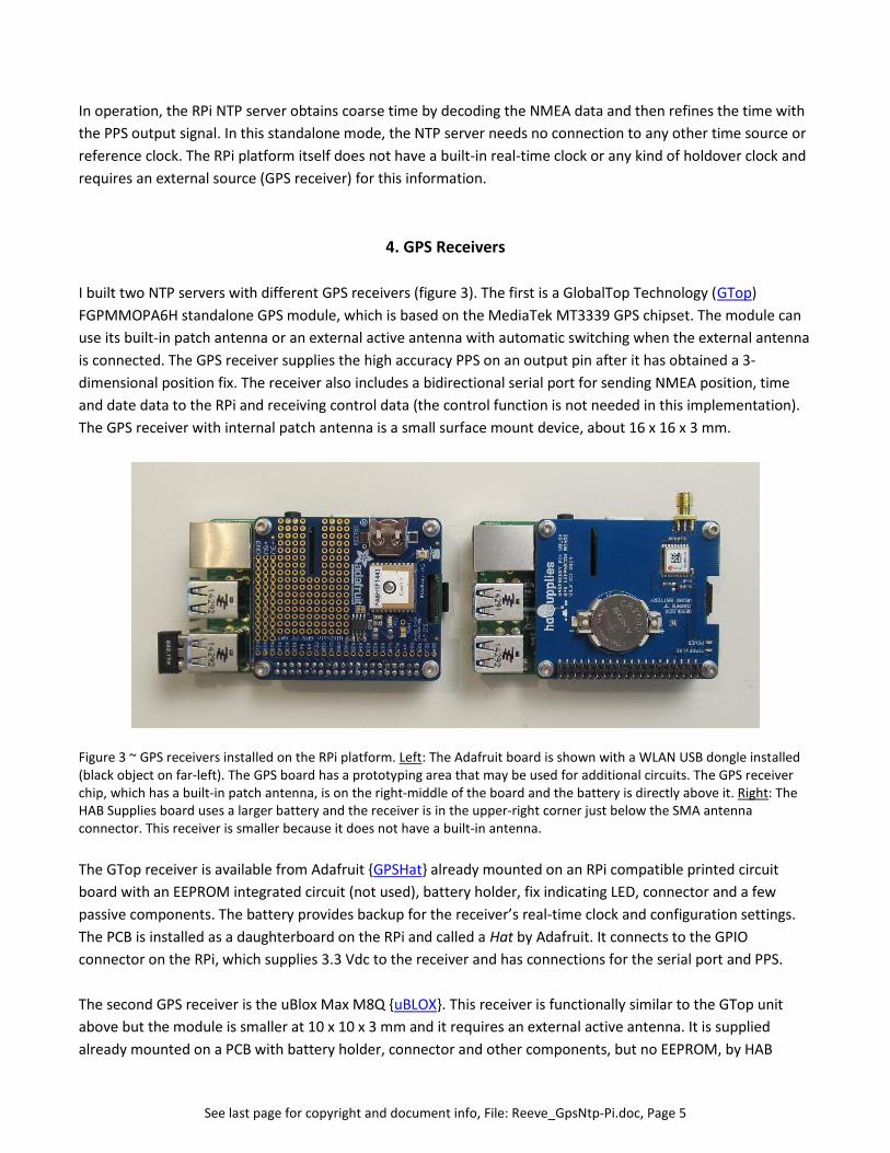
I built two NTP servers with different GPS receivers (figure 3). The first is a GlobalTop Technology (GTop)
FGPMMOPA6H standalone GPS module, which is based on the MediaTek MT3339 GPS chipset. The module can
use its built-in patch antenna or an external active antenna with automatic switching when the external antenna
is connected. The GPS receiver supplies the high accuracy PPS on an output pin after it has obtained a 3-
dimensional position fix. The receiver also includes a bidirectional serial port for sending NMEA position, time
and date data to the RPi and receiving control data (the control function is not needed in this implementation).
The GPS receiver with internal patch antenna is a small surface mount device, about 16 x 16 x 3 mm.
Figure 3 ~ GPS receivers installed on the RPi platform. Left: The Adafruit board is shown with a WLAN USB dongle installed(black object on far-left). The GPS board has a prototyping area that may be used for additional circuits. The GPS receiverchip, which has a built-in patch antenna, is on the right-middle of the board and the battery is directly above it. Right: TheHAB Supplies board uses a larger battery and the receiver is in the upper-right corner just below the SMA antennaconnector. This receiver is smaller because it does not have a built-in antenna.
The GTop receiver is available from Adafruit {GPSHat} already mounted on an RPi compatible printed circuit
board with an EEPROM integrated circuit (not used), battery holder, fix indicating LED, connector and a few
passive components. The battery provides backup for the receiver’s real-time clock and configuration settings.
The PCB is installed as a daughterboard on the RPi and called a Hat by Adafruit. It connects to the GPIO
connector on the RPi, which supplies 3.3 Vdc to the receiver and has connections for the serial port and PPS.
The second GPS receiver is the uBlox Max M8Q {uBLOX}. This receiver is functionally similar to the GTop unit
above but the module is smaller at 10 x 10 x 3 mm and it requires an external active antenna. It is supplied
already mounted on a PCB with battery holder, connector and other components, but no EEPROM, by HAB
See last page for copyright and document info, File: Reeve_GpsNtp-Pi.doc, Page 6
Supplies {GPSHAB}. As with the Adafruit unit, the HAB board installs as a daughterboard and receives power
from the RPi.
Both receivers have a real-time clock (RTC) that can operate from a battery backup when power is removed. The
battery backup retains this data in RAM to improve satellite acquisition time when power is restored. This is
called a warm-start or hot-start depending on the length of the power loss. A cold-start is when the receiver has
no previous data in RAM and power is applied. In my tests, warm-starts typically required < 1 min even when the
antennas did not have a clear view of the sky. Hot-starts typically required a few seconds.
The cold-start sensitivity of both receivers is worse than after satellite acquisition is completed and the receiver
transitions to tracking mode. When in tracking mode the sensitivity improves by about 20 dB. Both receivers can
concurrently receive GPS and GLONASS satellites in 66 channels (GTop) or 72 channels (uBlox),
and the uBlox receiver also can receive the BeiDou satellites.
Both receivers have an onboard RF connector for an external active antenna. The Adafruit board
uses a tiny U.FL (male) connector and the HAB Supplies board uses an SMA (female). Both connectors and their
PCB attachments are relatively fragile (especially so for the tiny U.FL connector) and thus require a flexible
pigtail or jumper for connection to the main antenna cable to relieve mechanical stress. The U.FL connector on
the Adafruit Hat is not designed for routine connection and disconnection and is rated for only 30
connect/disconnect cycles. The GPS receivers use the L1 band at about 1575 MHz. At this frequency coaxial
cable loss can be significant if the cable is long, nullifying the gain of an active antenna.
During tests, I had very good results by simply placing the RPi with GPS daughterboard (Adafruit) or the active
antenna (HAB Supplies) near a window. I also found that both receivers can acquire satellites when in my lab,
which is on the lower level with no windows that have a clear view of the sky (trees and interior walls obstruct
the view).
I did additional tests on the GTop receiver with its built-in antenna. While it was sitting on a north-facing
windowsill (worst case for satellite view) and in tracking mode, I placed a sheet of insulated aluminum foil over
the entire RPi assembly for several hours with no obvious ill-effects. I also placed it in a cardboard box with no
problems. The only way I could prevent GPS lock was to place a small kitchen LCD television within about 30 cm
and turn the TV on. The RFI from the TV definitely caused satellite acquisition problems. Overall, I found the
GTop receiver to be a slightly better than the U-Blox receiver in the NTP server application in terms of clock
offsets, but both receivers are adequate.
5. System Packaging
In a practical application, the RPi platform with GNSS receiver would be packaged in a metal enclosure to
provide mechanical protection. In such a setup, the GTop receiver would have to be used with an external
antenna. In one of my prototype systems, I used an extruded aluminum enclosure and a small 5 W dc-dc
converter, input power filter and a few other components (figure 4).

See last page for copyright and document info, File: Reeve_GpsNtp-Pi.doc, Page 7
Figure 4 ~ Upper-left: GpsNtp-Pi system prototype packaged in an extruded aluminum enclosure 162 x 105 x 57 mm(external antenna not shown) with a dc-dc converter. A WLAN dongle can be seen in a USB port. Upper-right: The rearpanel has a 2.1 x 5.5 mm dc power jack, power switch and power LED. Lower-left: The RPi is mounted on 6 mm standoffsand an adapter cable connects the Adafruit GPS receiver board to an SMA-F panel connector. Lower-right: A dc-dcconverter converts the nominal 9...15 Vdc input to 5 Vdc for the RPi and is mounted on a small printed circuit card with a Piinput EMI filter and polarity guard diode. The RPi board supplies 3.3 Vdc to the receiver.
6. Standalone Operation
The GpsNtp-Pi can be operated as a standalone time server or in conjunction with other
time servers on the LAN or WAN. Time servers have the best accuracy and performance
when operated in a peering arrangement in which the ensemble time typically is better
than the time produced by any one server. However, there may be situations where a
single, or standalone, time server is the only practical setup (figure 5). This would be
useful in installations that do not have access to other time servers on the same LAN or via
the internet or there is a need to minimize internet traffic.
During development of this project, attaining true standalone operation of the GpsNtp-Pi was problematic. In
particular, I found that if the power was removed from the RPi and GPS receiver for more than about 4 hours,
the NTP protocol would not synchronize with the GPSD shared memory data and PPS. The GPS receiver real-

See last page for copyright and document info, File: Reeve_GpsNtp-Pi.doc, Page 8
time clocks have a battery backup and continue running after power removal. When repowered the current
time is used to start the synchronization process, but this was not happening. Through a series of lengthy tests, I
traced this to the default settings in the shared memory driver for the GPS serial data. After changing the
default, the system will acquire and track the correct time within a few minutes after power is reapplied
regardless of the outage length.
AC PowerAdapter
Local AreaNetwork
Ethernet
Power
Internet
NTP Server usingRaspberry Pi
Model B+
InternetRouter
NTPClient
5 V
OptionalWLAN
GNSS Receiver
PPSNMEA3.3 V
NTPClient
NTPClient
GNSSSatellite
Figure 5 ~ In the standalone mode, the GpsNtp-Pi time server is operated without network connections to any other timeserver but still can serve time over the LAN or WAN.
7. Hardware and Software
Hardware: This project was developed on an unmodified Raspberry Pi model B+. It most likely will work on the
model B but has not been tested. The RPi is operated “headless”; that is, it is used without a directly connected
keyboard, mouse or monitor. All provisioning is done from a PC running a Secure Shell (SSH) terminal program
and connected to the same LAN as the RPi. The hardware requirements are minimal and costs are low (table 1).
Table 1 ~ Hardware Requirements and Costs
Item Adafruit HAB Supplies
Base system Raspberry Pi B+, 35 USD Raspberry Pi B+, 35 USD
GPS receiver assemblyUltimate GPS Hat for Raspberry Pi
{GPSHat}, 45 USDRaspberry Pi+ GPS Expansion
Board {GPSHAB}, 70 USDExternal active antenna Optional, 13 USD Required, 15 USDInternal patch antenna Yes NoSoldering required Yes YesMounting hardware required Yes YesRPi power supply 5 Vdc 10 W 5 Vdc 10 W

See last page for copyright and document info, File: Reeve_GpsNtp-Pi.doc, Page 9
Software: The system uses the Raspbian distribution, which is a version of Linux. Although the software includes
NTPD it must be recompiled to include PPS support. GPSD also must be installed. All programs and applications
may be freely downloaded from the internet, and installation details are provided in the setup guide.
8. Performance Measurements
The time domain quality of a clock is specified by its accuracy and stability, where accuracy indicates how close
the clock time is to UTC and stability indicates how well it maintains a constant time interval (for example, 1 s).
Clock measurements are made at regular intervals and then used to compute statistical variances
– Allan Variance (AVAR), Modified Allan Variance (MVAR) and Allan Time Variance (TVAR) or their
square roots Allan Deviation (ADEV), Modified Allan Deviation (MDEV) and Allan Time Deviation
(TDEV) – over various averaging intervals. I used NTPD’s built-in statistics logs and the Alavar
software application to perform the computations {Alavar}.
The PPS reference clock and associated processing determines the overall stability of the GpsNtp-Pi time server
with respect to UTC. Measurements were made using a flag in the PPS software driver that provides a time
stamp for each PPS. First, the time server was operated in standalone mode for at least 24 hours to allow NTP
synchronization to stabilize. The flag then was set and the server run for another 24 hours to gather the offset
data (specifically, the clockstats parameter).
One system was operated in standalone mode and the other in pooled mode to provide comparative
measurements. The Adafruit system with GTop receiver was setup in standalone mode to use its built-in
antenna and a wireless network connection, and the HAB Supplies system with uBlox receiver was setup in
pooled mode to use an inexpensive external patch antenna and a wired network connection. In all measurement
setups, the systems were placed on or near the sill of a north-facing window, which perhaps is a worst-case
scenario for measuring performance under poor operating conditions. The network connection type does not
affect system performance when in standalone mode (no network connection is needed) but can affect
operation in pooled mode because the time messages from external servers are sent and received in a variable
network transmission environment. It should be noted that the network connection type can affect the time
stability of an NTP client. During my measurements, the ambient temperature near a window varied throughout
the day and night, but I made no measurements of the range.
Both systems show a small offset from perfect synchronization with UTC as indicated by the basic data in Table 2
and the TDEV plots, which have an average slope of about 1 μs/s [figure 6(a) and (b)]. Most of the offset likely is
due to the processing time within the RPi platform. If there had been no offset, the TDEV plots would have zero
slopes. The clock stability indicated by the Allan Deviation (ADEV) is approximately 1.0 to 1.5 μs. Much of this
probably is due to the environment but processing variations in the RPi also have an effect. The ADEV plots for
perfectly stable clocks would be straight horizontal lines (zero slopes). The original data [figure 7(a) and (b)]
shows some systematic variations, which are discussed below.
The TDEV and ADEV measurements are several orders of magnitude worse than atomic clocks, which typically
have 0.02 to 0.5 ns accuracy and 30 to 50 ps stability, or even good oven-controlled crystal oscillators (OCXO).
An oven-controlled oscillator typically has 10 ns accuracy and 1 ps stability. High-performance clocks usually

See last page for copyright and document info, File: Reeve_GpsNtp-Pi.doc, Page 10
include an OCXO for short-term stability and a cesium or rubidium atomic oscillator for long-term stability.
Rubidium clocks often are disciplined by a GNSS receiver to reduce effects of aging and drift.
The GpsNtp-Pi uses a GNSS receiver, which provides accuracy traceable to an ensemble of atomic clocks, but it
does not have a crystal oscillator to improve its short-term performance. Nevertheless, the GpsNtp-Pi
performance is quite remarkable considering its simplicity and cost.
Table 2 ~ GpsNtp-Pi Statistics
SystemReceiver
Average offset(s)
Standarddeviation (s)
ADEV slopeStability
(ADEV at τ = 1 s)Remarks
GTop 77.318 10 65.928 10 0.099 61.107 10 Standalone, wireless network
uBlox 73.376 10 64.651 10 –0.000132 61.589 10 Pooled, wired network
Figure 6(a) ~ TDEV (blue trace) andADEV (red trace) with error bars forGpsNtp-Pi based on Adafruit boardwith GTop receiver. Standalone mode
with 1 s sampling interval (τ = 1 s).
The TDEV plot indicates somevariation in offset for variousaveraging times. The ADEV plot showsthat the stability is the best when thevariance is calculated with anaveraging time of approximately 17 sand is the worst at 1000 s.
Figure 6(b) ~ TDEV (blue trace) andADEV (red trace) with error bars forGpsNtp-Pi based on HAB Suppliesboard with uBlox receiver. Pooled
mode with 1 s sampling interval (τ = 1
s). The TDEV plot shows a slightlymore constant offset than the GTopreceiver system. The ADEV plot showsthat the stability is the best when thevariance is calculated with anaveraging time of approximately 67 sand is the worst at 17 s.

See last page for copyright and document info, File: Reeve_GpsNtp-Pi.doc, Page 11
Figure 7(a) ~ Original data forGpsNtp-Pi based on Adafruitboard with GTop receiver taken
with 1 s sampling interval (τ = 1
s). The index is the samplenumber counted in sequencefrom the start time of 0000 UTC.The plot clearly showssystematic variations in thedata, most likely caused bytemperature variations. Asetback thermostat engages at0730 (index = 27 000 s) anddisengages 7 h later (index = 50000).
Figure 7(a) ~ Original data forGpsNtp-Pi based on HABSupplies board with uBloxreceiver taken with 1 s sampling
interval (τ = 1 s) . The index is
the sample number counted insequence from the start time of0000 UTC. The plot showssystematic data variationssimilar to 7(a) but of a differentcharacter.
The oscillatory behavior of the data plots, particularly evident for the GTop receiver, most likely indicates a
temperature influence on clock offset stability. At night the setback thermostat for the room lowers the
temperature as seen by the well between about 27000 and 50000 points. Each point is 1 s and the data starts at
0000 UTC (1500 local time). The temperature starts to drop around 0700 UTC (2200 local) and begins to rise 7 h
later. The HAB Supplies unit was farther from the baseboard heater and registered more rapid variations,
possibly related to the faster sampling of the GPSD data on the uBlox receiver.
Future work includes more measurements:
A more complete characterization of the GpsNtp-Pi would entail a total of four measurements on each unit:
Measure each unit with and without a pool of time servers and wired and wireless network connections (it
is expected that the network connection might affect only the measurements with a server pool and that a
wireless connection will result in much higher time jitter)
It would be interesting to see if using an external antenna with the GTop receiver changes any of the results
It would be useful to measure the units while in a temperature controlled enclosure (requiring external
antennas on both units)

See last page for copyright and document info, File: Reeve_GpsNtp-Pi.doc, Page 12
Measurements over periods longer than 24 h would be useful for demonstrating long-term stability (or
instability)
9. References, Web Links and Further Reading
{Alavar} http://www.alamath.com/{ReeveCPi} http://www.reeve.com/Documents/Articles%20Papers/Reeve_Callisto-Pi.pdf{GPSHAB} http://ava.upuaut.net/store/index.php?route=product/product&path=59_60&product_id=117{GPSHat} https://blog.adafruit.com/2014/12/26/new-product-adafruit-ultimate-gps-hat-for-raspberry-pi-a-
or-b-mini-kit/{GpsNtp-Pi} http://www.reeve.com/Documents/Articles%20Papers/Reeve_GpsNtp-Pi_Setup.pdf{GTOP} http://www.gtop-tech.com/en/product/LadyBird-1/MT3339_GPS_Module_04.html{LWATV} http://www.reeve.com/Documents/Articles%20Papers/Reeve_RPi-LWATV.pdf{NMEA} http://www.gpsinformation.org/dale/nmea.htm{NTPOrg} http://www.ntp.org{RvTime} http://www.reeve.com/Documents/Articles%20Papers/Reeve_LeapSec2015.pdf{uBLOX} http://www.u-blox.com/en/gps-modules/pvt-modules/max-m8-series-concurrent-gnss-
modules.html
Acknowledgements: David J. Taylor worked with me to determine the proper settings in the ntp.conf file forstandalone operation. His website at http://satsignal.eu/ntp/Raspberry-Pi-NTP.html includes many helpfuldetails and includes performance charts for his own RPi time servers.

See last page for copyright and document information, File: Reeve_GpsNtp-Pi.doc, Page 13
Document information
Author: Whitham D. Reeve
Copyright: © 2015 W. Reeve
Revision: 0.0 (Original draft started, 06 Feb 2015)
0.1 (Corrections and updates per working system, 07 Feb 2015)
0.2 (Numerous updates, 12 Feb 2015)
0.3 (Minor edits for clarification, 16 Feb 2015)
0.4 (Revised settings for standalone operation, 24 Feb 2015)
0.5 (Split away installation and operation sections, 24 Feb 2015)
0.6 (Many revisions to make a standalone document, 27 Feb 2015)
0.7 (Added packaged system pictures, 13 Mar 2015)
0.8 (Adjusted paragraph spacing, 25 Mar 2015)
0.9 (Minor revisions and preparation for distribution, 29 Mar 2015)
1.0 (Distribution, 6 Apr 2015)
Word count: 4724File size: 3376640