Gorakhpurmechanicalworkshopsummertrainingreport 141115125812 Conversion Gate02
48
“INDUSTRIAL TRAINING REPORT” NORTH EAST RAILWAY GORAKHPUR (U.P) INDUSTRIAL TRAINING REPORT 2015-16 SUBMITTED BY ANAND KUMAR Roll No. 1213240021 B.Tech(4 th year)
-
Upload
anand-kumar -
Category
Documents
-
view
3 -
download
0
description
Gorakhpurmechanicalworkshopsummertrainingreport
Transcript of Gorakhpurmechanicalworkshopsummertrainingreport 141115125812 Conversion Gate02
“INDUSTRIAL TRAINING REPORT”
NORTH EAST RAILWAY GORAKHPUR (U.P)
INDUSTRIAL TRAINING REPORT 2015-16
SUBMITTED BY
ANAND KUMAR
Roll No. 1213240021 B.Tech(4th year) Mechanical Engineering
An Industrial Training Report
Submitted for partial fulfillment for the award of degree of
BACHELOR OF TECHNOLOGY IN MECHANICAL
ENGINEERING
DEPARTMENT OF MECHANICAL ENGINEERING
GREATER NOIDA INSTITUTE OF TECHNOLOGY
GREATER NOIDA - 201308
(2015 -16)
ACKNOWLEDGEMENT
Mechanical workshop of north eastern railway, Gorakhpur is a well-known public sector industry. I am deeply grateful to Chief Workshop Manager, Who gave me a chance to have an insight of the vocational training of four weeks.
By seeing the good management of the plant, I learnt a lesson three D’s Discipline, Determination and Devotion .I also grasp an idea of state-of-the-art technology and plant.
I am also grateful to each of my chief-instructor MR. ANIRUDH SHINGH who provided me every help and removed my doubts about the particular shop.
LIST OF CONTENT
1. INTRODUCTION OF INDIAN RAILWAY
2. MACHINE SHOP
3. PAINTING SHOP
4. WHEEL SHOP
5. SPRING SHOP
6. HEAT TREATMENT SHOP
7. JIG AND FIXTURE SHOP
8. BRAKING SYSTEM
9. SHELL SHOP
10. MATERIAL HANDLING SYSTEM
11. REFERENCES
INTRODUCTION
Indian Railway is an Indian state-owned enterprise, owned and operated by
the Government of India through the Ministry of Railways. It is one of the
world's largest railway networks comprising 115,000 km (71,000 mi) of track
over a route of 65,436 km (40,660 mi) and 7,172 stations.In 2013–14, IR carried
8,425 million passenger’s annually or more than 23 million passengers daily
(roughly half of which were suburban passengers) and 1050.18 million tons of
freight in the year. In 2013–2014 Indian Railways had revenues of 1441.67
billion (US$23 billion) which consists of 940.0 billion (US$15 billion) from
freight and 375.0 billion (US$6.1 billion) from passengers tickets.
Railways were first introduced to India in the year 1853 from Bombay to Thane.
In 1951 the systems were nationalised as one unit, the Indian Railways,
becoming one of the largest networks in the world. IR operates bothlong
distance and suburban rail systems on a multi-gauge network
of broad, metre and narrow gauges. It also
owns locomotive and coach production facilities at several places in India and
are assigned codes identifying
Their gauge, kind of power and type of operation. Its operations cover also
provides limited international services to Nepal, Bangladesh and Pakistan.
Indian Railways is the world's seventh largest commercial or utility employer,
by number of employees, with over 1.307 million employees. As for rolling
stock, IR holds over 239,281 Freight Wagons, 62,924 Passenger Coachesand
9,013 Locomotives (43 steam, 5,345 diesel and 4,568 electric locomotives). The
trains have a 5 digit numbering system and runs 12,617 passenger trains and
7421 freight trains daily. As of 31 March 2013, 20,884 km (12,977 mi) (31.9%)
of the total 65,436 km (40,660 mi) route length was electrified, Since1960,
almost all electrified sections on IR use 25,000 Volt AC traction through
overhead catenary delivery.
DIVISION IN INDIAN RAILWAY
The Indian Railways is divided into zones, which are further sub-divided into
divisions, each having a divisional headquarters. There are a total of sixty-nine
divisions.
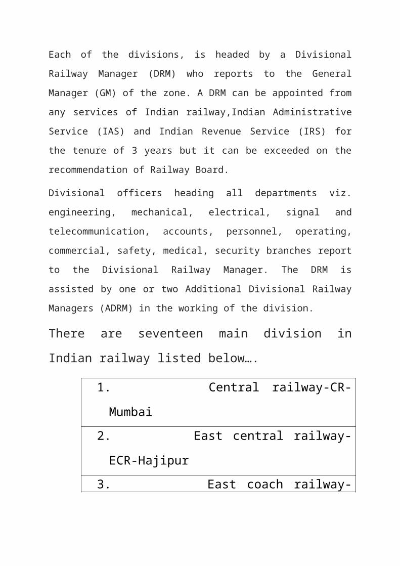
Each of the divisions, is headed by a Divisional Railway Manager (DRM) who
reports to the General Manager (GM) of the zone. A DRM can be appointed
from any services of Indian railway,Indian Administrative Service (IAS) and
Indian Revenue Service (IRS) for the tenure of 3 years but it can be exceeded
on the recommendation of Railway Board.
Divisional officers heading all departments viz. engineering, mechanical,
electrical, signal and telecommunication, accounts, personnel, operating,
commercial, safety, medical, security branches report to the Divisional Railway
Manager. The DRM is assisted by one or two Additional Divisional Railway
Managers (ADRM) in the working of the division.
There are seventeen main division in Indian railway listed
below….
1. Central railway-CR-Mumbai
2. East central railway-ECR-Hajipur
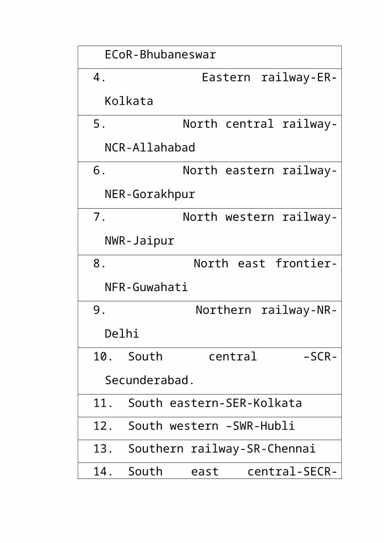
3. East coach railway-ECoR-Bhubaneswar
4. Eastern railway-ER-Kolkata
5. North central railway-NCR-Allahabad
6. North eastern railway-NER-Gorakhpur
7. North western railway-NWR-Jaipur
8. North east frontier-NFR-Guwahati
9. Northern railway-NR-Delhi
10. South central –SCR-Secunderabad.
11. South eastern-SER-Kolkata
12. South western –SWR-Hubli
13. Southern railway-SR-Chennai
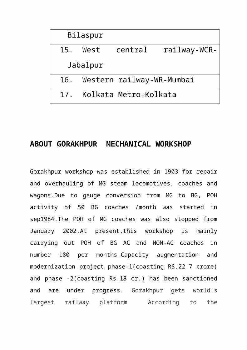
14. South east central-SECR-Bilaspur
15. West central railway-WCR-Jabalpur
16. Western railway-WR-Mumbai
17. Kolkata Metro-Kolkata
ABOUT GORAKHPUR MECHANICAL WORKSHOP
Gorakhpur workshop was established in 1903 for repair and overhauling of MG
steam locomotives, coaches and wagons.Due to gauge conversion from MG to
BG, POH activity of 50 BG coaches /month was started in sep1984.The POH of
MG coaches was also stopped from January 2002.At present,this workshop is
mainly carrying out POH of BG AC and NON-AC coaches in number 180 per
months.Capacity augmentation and modernization project phase-1(coasting
RS.22.7 crore) and phase -2(coasting Rs.18 cr.) has been sanctioned and are
under progress. Gorakhpur gets world's largest railway platform According to
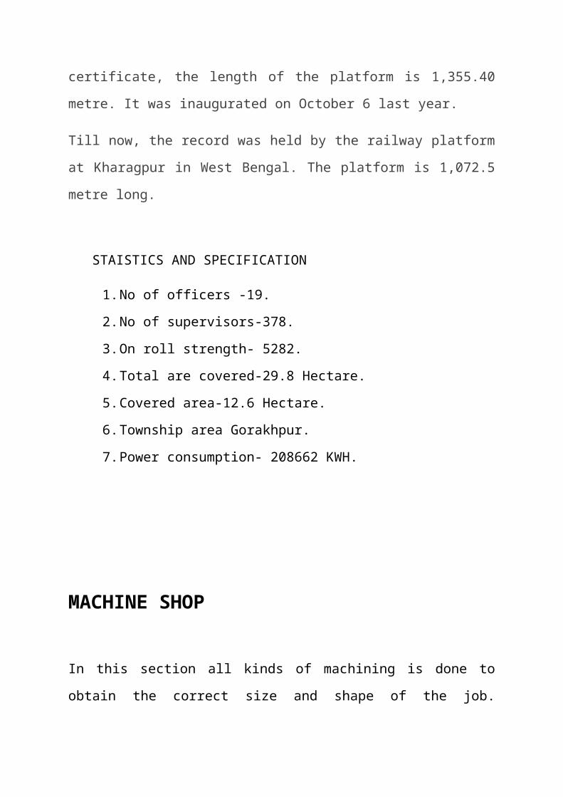
the certificate, the length of the platform is 1,355.40 metre. It was inaugurated
on October 6 last year.
Till now, the record was held by the railway platform at Kharagpur in West
Bengal. The platform is 1,072.5 metre long.
STAISTICS AND SPECIFICATION
1. No of officers -19.
2. No of supervisors-378.
3. On roll strength- 5282.
4. Total are covered-29.8 Hectare.
5. Covered area-12.6 Hectare.
6. Township area Gorakhpur.
7. Power consumption- 208662 KWH.
MACHINE SHOP
In this section all kinds of machining is done to obtain the correct size and
shape of the job. Besides, machining of steel job, Aluminum-plates are also
machined here. Machining is other performed manually or on automatic
machines.
Machines are two types…
1. AUTOMATIC.
2. MANUALLY.
There are three types of automatic machine.
1. Numerical control.
2. Computer numerical control.
3. Direct numerical control machine.
NUMERICAL CONTROL-The machining parameter are feed from the
control panel by pushing buttons .The job is machined according to the
parameter There are N.C. boring machine in this shop.
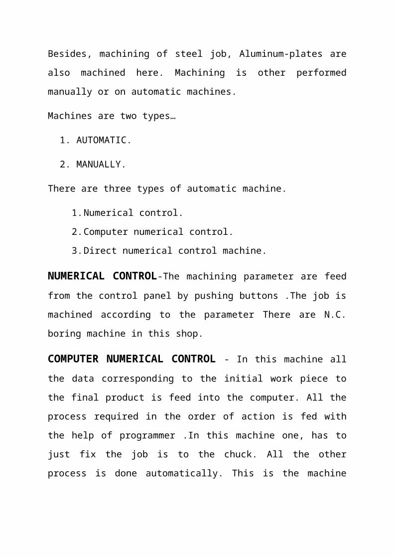
COMPUTER NUMERICAL CONTROL - In this machine all the data
corresponding to the initial work piece to the final product is feed into the
computer. All the process required in the order of action is fed with the help of
programmer .In this machine one, has to just fix the job is to the chuck. All the
other process is done automatically. This is the machine use for large scale
production. In this shop there is one CNC chucker turret Lathe machine.
DIRECT NUMERICAL CONTROL-This machine is controlled by
installing a control room away from the work place .These machine are D.N.C.
machine. These are fully automated .The machine shop is divided into different
divisions to the task accomplished .Theses sections are-
1. Capstan and turret lathe section.
2. Milling section.
3. Drilling section.
4. Central lathe section.
5. Heavy machine section.
MANUALLY OPERATED MACHINE
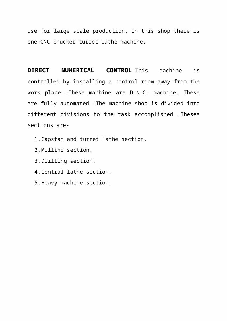
DRILLING SECTION-Drilling operation is carried out here. A large for
the operation .To complete the operation faster a few gauge milling machine are
also provides.
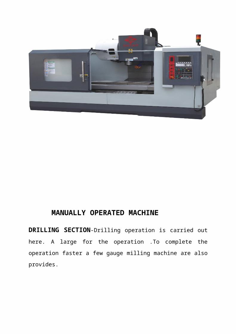
DRILLING MACHINE
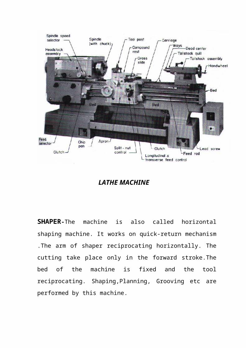
CENTER LATHE SECTION-Heavier lathes are provided in this
section. All the lathes have four jaws chuck for better holding centering is
done either manually or with the help of universal scriber. All kinds of
turning are performed here. Parting off is other major operation done.
LATHE MACHINE
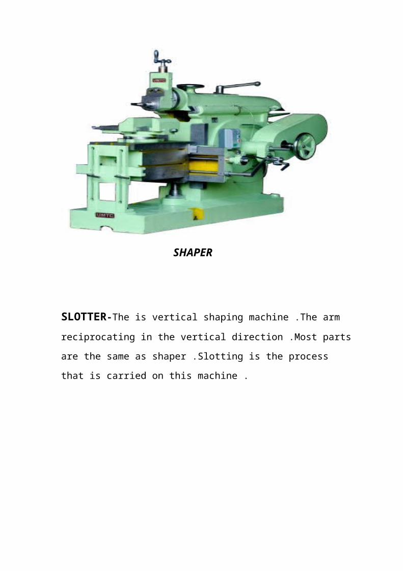
SHAPER-The machine is also called horizontal shaping machine. It works
on quick-return mechanism .The arm of shaper reciprocating horizontally.
The cutting take place only in the forward stroke.The bed of the machine is
fixed and the tool reciprocating. Shaping,Planning, Grooving etc are
performed by this machine.
SHAPER
SLOTTER-The is vertical shaping machine .The arm reciprocating in the
vertical direction .Most parts are the same as shaper .Slotting is the process
that is carried on this machine .
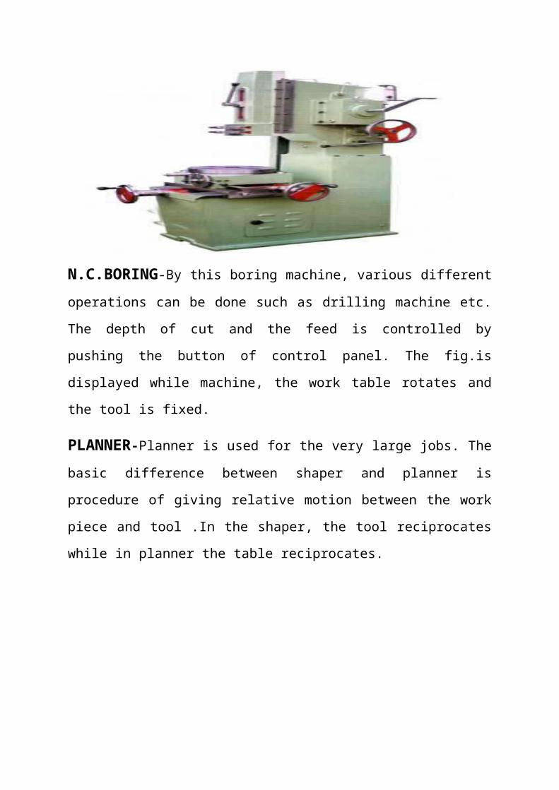
N.C.BORING-By this boring machine, various different operations can be
done such as drilling machine etc. The depth of cut and the feed is controlled by
pushing the button of control panel. The fig.is displayed while machine, the
work table rotates and the tool is fixed.
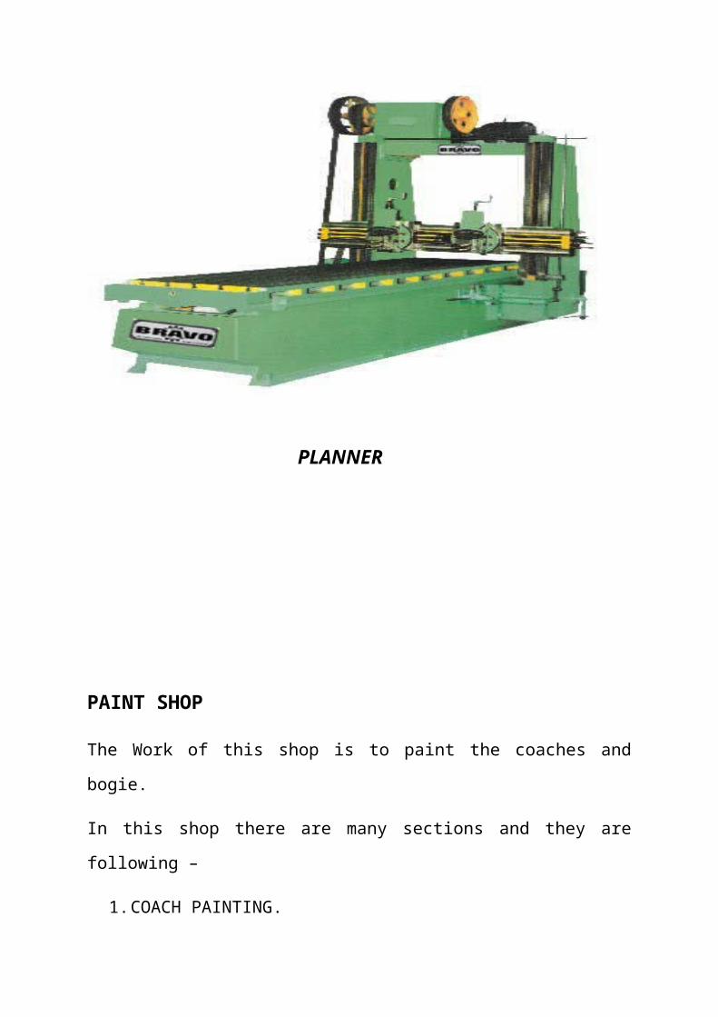
PLANNER-Planner is used for the very large jobs. The basic difference
between shaper and planner is procedure of giving relative motion between the
work piece and tool .In the shaper, the tool reciprocates while in planner the
table reciprocates.
PLANNER
PAINT SHOP
The Work of this shop is to paint the coaches and bogie.
In this shop there are many sections and they are following –
1. COACH PAINTING.
2. LETTER SECTION.
3. TRIMMING SECTION.
4. CORROSION SECTION.
5. POLSIH SECTION.
PURPOSE OF PAINTING-
1. FOR PROTECTION AGAINST COROSION.
2. FOR DECORATION.
3. FOR COVERING.
MATERIAL USED IN PAINTING –
1. PAINT MATERIALS.
2. ENEMAL MATERIALS.
3. VARNISH MATERIALS.
4. LACQUER MATERIALS.
PAINT MATERIALS-
1. BASE.
2. BINDER.
3. THINNER.
4. DRIER.
5. PIGMENT.
6. INERT OR FILLER MATERIAL.
PAINT BOX
THINNER
THE MAIN PROCESS INVOLVE IN PAINTING – Firstly, Putin is
prepared and it gets filled at the places where holes and cracks has been found.
Secondly, the primer is put on the body and then finally painting is done in
order to give the body desire shape.
The overhauling of the coaches has been in given time interval it improves the
quality of coaches and it also prevents the coaches from break down. The
maintenance of coaches is according to time being is done as following-
1. MAIL EXPRESS- 12 MONTHS.
2. PASSENGER- 18 MONTHS.
3. NEWLY COACHES- 24 MONTHS.
TYPES OF PAINT-
1. Aluminum Paint.
2. Anti-corrosive.
3. Asbestos paint.
4. Bituminous paint.
5. Cellule paint.
6. Cement paint.
7. Distemper.
8. Plastic paint.
9. Graphite paint.
10. Oil paint
11. Silicate paint.
12. Luminous paint.
13. Enamel paint.
14. Emulsion paint.
WHEEL SHOP
In this shop, repair work of the wheel and axel is under taken. As it is known
that, the wheel wears throughout its life. When at work the profile and
diameter of the wheel constantly changes. To improve it’s working and for
security reason, it is repaired and given correct profile with proper diameter.
The diameter of new wheel is-
Type Wheel dia. Distance b/w
journal center (mm)
Journal
size(mm)
Axel wheel
seat dia.
(mm)
ICF 915 2159 120*113.5 172,0.25,0.35
BMEL 915 2210.2 120*179 171,0.45,0.63
Wheel can be used certain minimum diameter after which it is discarded.
The diameter of the wheel when it is condemned are-
S.N TYPE OF WHEEL DIAMETER IN (MM)
1. ICF/BMEL SOLID 915-813
2. ICF TIRED 915-851
3. BMEL TIRED 915-839
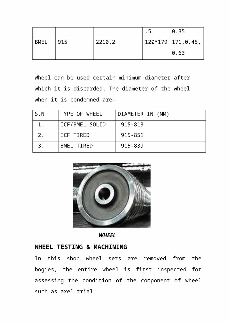
WHEEL
WHEEL TESTING & MACHINING
In this shop wheel sets are removed from the bogies, the entire wheel is first
inspected for assessing the condition of the component of wheel such as axel
trial
wheel disc and guttering.
The shop consist of-
(1) Axel journal testing lathe.
(2) Hydraulic wheel press with facility of mounting.
(3) Axel turning lathe.
(4) Vertical turning lathe.
Axel journal turning lathe.
On this lathe, the diameter of the axel is brought to the correct diameter. The
cutting tool is used of carbon tool.
Hydraulic wheel press with a facility of mounting.
The wheel is pressed on the axel with the help of this machine. A calculated
amount of pressure is applied and the wheel is pressed.
Axel turning machine.
External and internal diameter is corrected by this lathe, wheel is tightened on
the rotating clutch. The stationary is carbide tool cut the wheel to correct
diameter.
Wheel Profile Lathe.
The profile of the wheel is repaired on this machine. Correct profile is cut by
carbide tool.
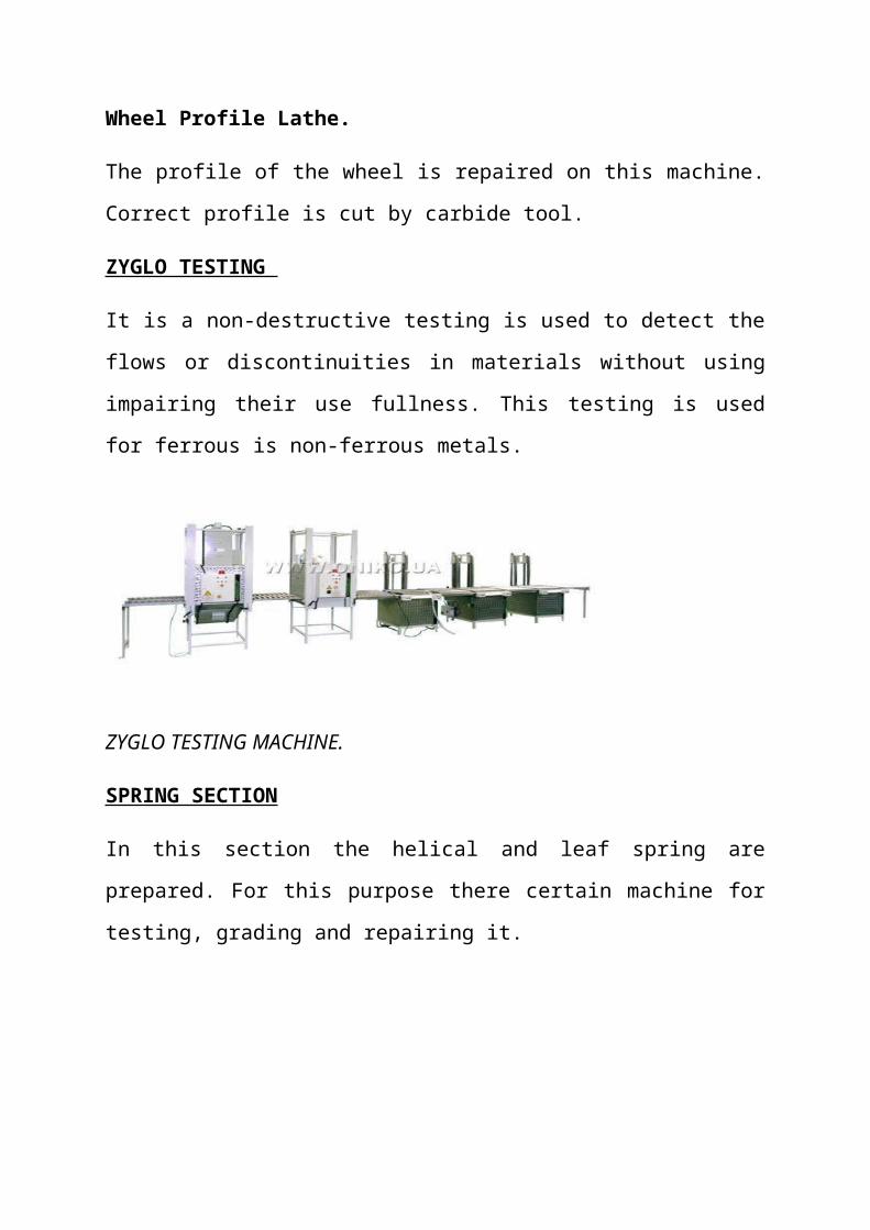
ZYGLO TESTING

It is a non-destructive testing is used to detect the flows or discontinuities in
materials without using impairing their use fullness. This testing is used for
ferrous is non-ferrous metals.
ZYGLO TESTING MACHINE.
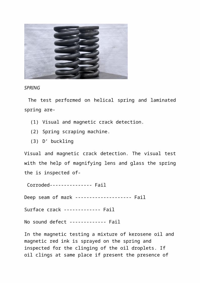
SPRING SECTION
In this section the helical and leaf spring are prepared. For this purpose there
certain machine for testing, grading and repairing it.
SPRING
The test performed on helical spring and laminated spring are-
(1) Visual and magnetic crack detection.
(2) Spring scraping machine.
(3) D’ buckling
Visual and magnetic crack detection. The visual test with the help of
magnifying lens and glass the spring the is inspected of-
Corroded--------------- Fail
Deep seam of mark -------------------- Fail
Surface crack ------------- Fail
No sound defect ------------- Fail
In the magnetic testing a mixture of kerosene oil and magnetic red ink is sprayed on the spring and inspected for the clinging of the oil droplets. If oil clings at same place if present the presence of crack. There are variation reasons for the failure of the helical spring such as free height load test, dent mark, corrosion and breakage.
CAUSE PERCENTAGE OF FAILURE Free of height 8.93%Load test 82.08%Dent mark, corrosion &breakage 08.39%
SPRING SCRAGING
After the buckling test, the spring should be put on scraping machine and the camber should be measured. In this test, the spring should be pressed quickly and camber should be measured 2 times. The spring should be test such as, it should not be more than ½ of the plate. In helical spring scraping, the spring is kept on the machine and its free height us measure. Now the spring is compressed, under certain and its compression is noted down. The compression is matched from the table provided for springs. If the compression matches, the spring is passed otherwise rejected.
VARIOUS REASONS OF SPRING FAILURE ARE AS FOLLOW-
1. Over camber of the spring.2. Short camber of the spring.3. Leaf broken.4. Gap between the leaves of the spring.
D’ BUCKLING
On this machine, buckling is performed on laminated spring. The leaves of the springs are assembled and pressed. Now it is put on the buckling machine axial and longitudinal forces are applied.
VARIOUS OTHER MACHINES IN THIS SECTION-
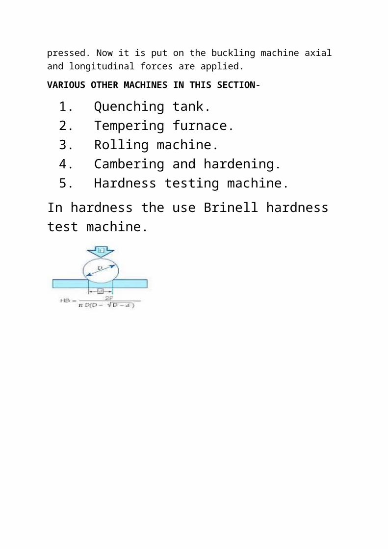
1. Quenching tank.2. Tempering furnace.3. Rolling machine.4. Cambering and hardening.5. Hardness testing machine.
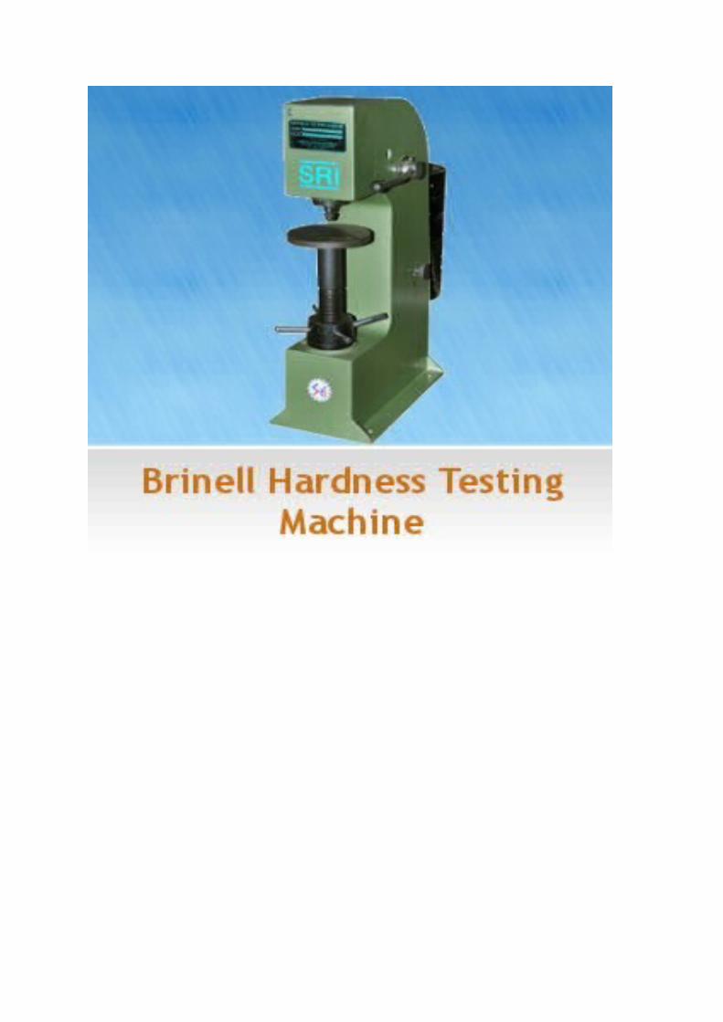
In hardness the use Brinell hardness test machine.
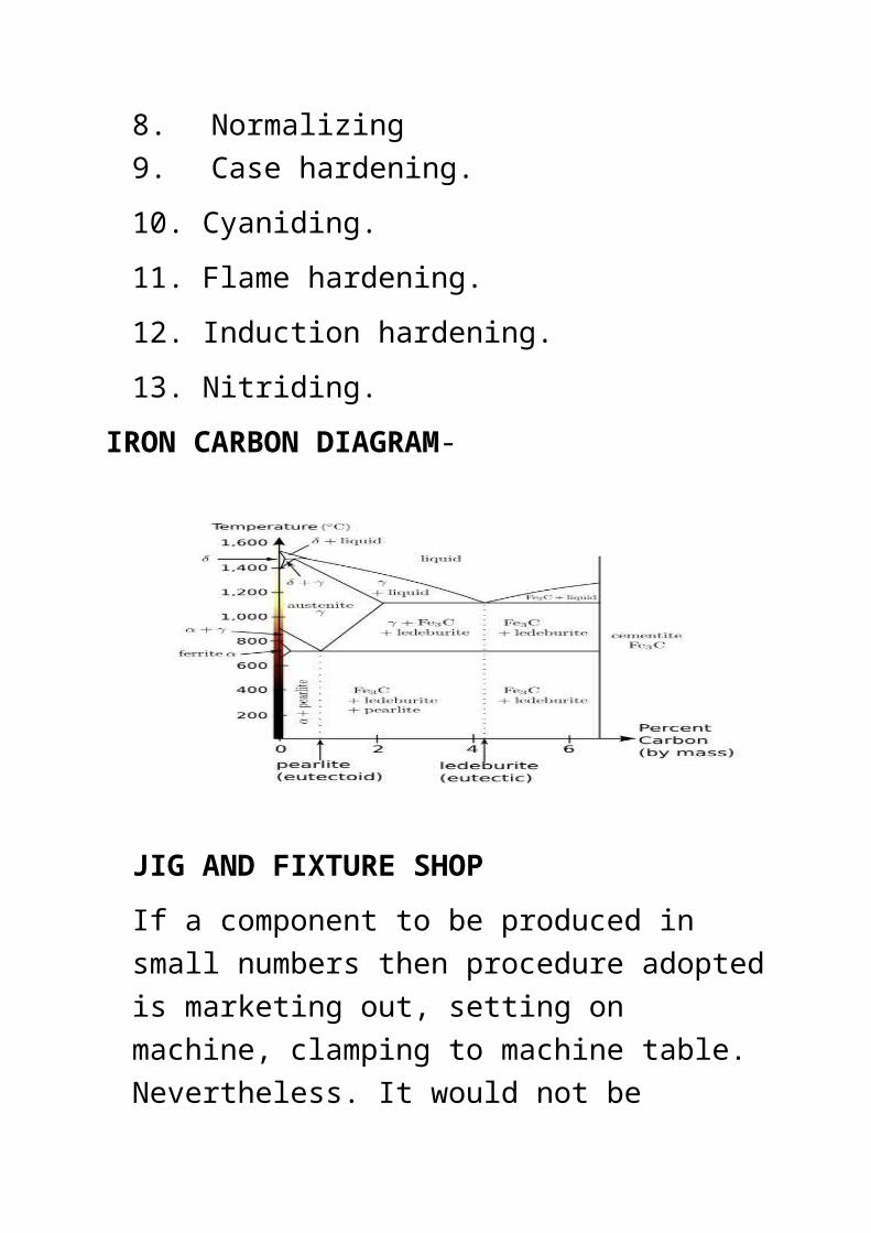
HEAT TREATMENT SHOP
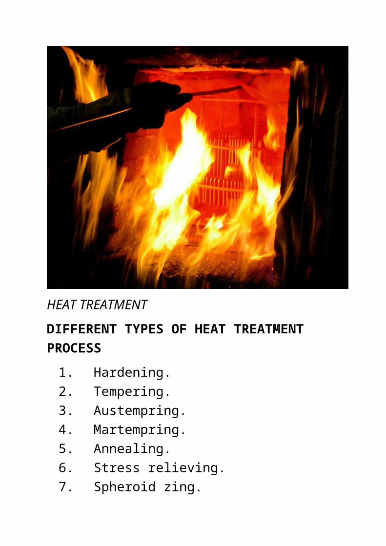
Heat treatment is the process of heating and cooling of a material to change its physical and mechanical properties without changing the original shape and size. Heat treatment of steel is often associated with increasing its strength, but can also be used to improve machinability, formability, restoring ductility, etc. Basic heat treatment process for steels are described in the following subsections.
HEAT TREATMENT
DIFFERENT TYPES OF HEAT TREATMENT PROCESS
1. Hardening.2. Tempering.3. Austempring.4. Martempring.5. Annealing.6. Stress relieving.7. Spheroid zing.8. Normalizing9. Case hardening.
10. Cyaniding.
11. Flame hardening.
12. Induction hardening.
13. Nitriding.
IRON CARBON DIAGRAM-
JIG AND FIXTURE SHOP
If a component to be produced in small numbers then procedure adopted is marketing out, setting on machine, clamping to machine table. Nevertheless. It would not be suitable for producing same component in large quantities because of economic reason. A faster and more profitable method calls for a device JIG&FIXTURE.
JIGS
Jig may be described as a plate, or metal box, structure or a device usually made of which metal is clamped or fastened or located one after others for the other for specific operation in such a way that it will guide one or more cutting tools to the same position.
FIXTURE
This may be structure for locating holding and supporting a component or work piece securely in a definite position for a specific operation but it does not guide the cutting tool. The cutting tool are set in position by machine adjust or by trial& error method.
FIXTURE
DESIGN OF JIG& FIXTURES
1. Sharp corners may be avoided.2. Adjustment locator must be provided.3. Locating pins should be tapered.4. Quick acting, clamps should be provided.5. Safety criterion should be provided.6. Accuracy is the basic need should not be
compromised.
BRAKING SYSTEM
Working-By means of frictional force between wheel and brake pad.
Mainly two types of braking system is used-
1. Air-Braking system.2. Vacuum-brake system.
AIR BRAKING SYSTEM
This is new method of braking system, which is more efficient than the vacuum brakes. It is used at first in Rajdhani and satabdi coaches. Progress conversion of vacuum brakes in air-brake has being undertaken.
The main parts of air-brake system are following-
1. Brake cylinder.2. Brake pipe.3. Feed pipe.4. Distributer pipe.5. Angle lock.6. House pipe.7. Auxiliary reservoir.8. Guards van valve & pressure gauge.9. Isolating cock.
10.Passenger emerging alarm signal device.
11. Dirt collector.
Description of some important parts of air-braking system-
BRAKE CYLINDER-There are two 355 mm brake cylinder under frame, which is fed by common distributor valve. It has the piston-rod arrangement, which works under pressure. Brake cylinder is connected to distributor valve on one side and by pivot to the block cylinder.
BRAKE PIPE-This is charged from the locomotive at 5 kg/cm3 and causes application and release of brakes due to change in its pressure through the locomotive control system. The pipe linked to distributor system.
FEED PIPE- It having 6kg/cm3 pressure, and keeps the auxiliary reservoir charge at fuel pressure even when brakes are applied. Feed pipe are also connected to the distributor valve.
DISTRIBUTOR VALVE- It is connected to the brake pipe auxiliary reservoir and brake cylinder. It controls the pressure in the brake cylinder. It controls the pressure in the brake cylinder in proportion to the reduction of pressure in brake-pipe.
ANGLE COCK-It is use for alarming purpose.
HOUSE COUPLING- Both the brake-pipe and feed pipe are fitted to the angle cock outlet for the passage of compressed air from one coach to another mean of braided rubber and metal coupling.
GUARD VAN VALVE & PRESSURE GAUGE- These are provided in the guards compartments. These are provided to control the train movement.
ISOLATING COCK- Use for isolating the air from one point to the other point.
CHOKE- It is device for restricting the flow of air from one point brakes circuit to other point. The handle of this cock is kept parallel to the pipe to indicate that it is in open conditions.
SHELL SHOP
Shell shop is divided into two parts-
1. FITTING SHOP.2. WELDING SHOP.
CAUSEOF CORROSION-
1. WATER SLEEPAGE.2. AIR-TRAP BETWEENFLOOR AND PLYWOOD.3. FLYING BLAST (DUE TO FORMATION OF SPOT).
MAIN PARTS OF SHELL-Various parts of shell are as follows-
1. UNDER FRAME
(A)SOLE BAR
(B)HEAD STOCK ASSEMBLY.
(C)BODY BLOSTER ASSEMBLY.
(D)THROUGH FLOOR.
(E)CROPS BEARER.
(F)TUBULAR STRUCTURE.
2. SIDE BAR.
3. ROOF.
4. END BAR.
5. CENTER PIVOT (GUIDE OF TURNING OF TRAIN).
TYPES OF WELDING USED IN SHELL SHOP-
1. CO2 ARC WELDING.2. MANUAL METAL ARC WELDING.3. BHARAT CUTTING GAS.(B.C.G)4. LIQUEFIED PETROLEUM GAS.5. OXY-ACETELENE GAS WELDING.
Welding by torch
MATERIAL HANDLING SYSTEM
Material Handling is the field concerned with solving the pragmatic problems involving the movement, storage in a manufacturing plant or warehouse, control and protection of materials, goods and products throughout the processes of cleaning, preparation, manufacturing, distribution, consumption and disposal of all related materials, goods and their packaging.The focus of studies of Material Handling course work is on the methods, mechanical equipment, systems and related controls used to achieve these functions. The material handling industry manufactures and distributes the equipment and services required to implement material handling systems, from obtaining, locally processing and shipping raw materials to utilization of industrial feedstocks in industrialmanufacturing processes. Material handling systems range from simple pallet rack and shelving projects, to complex conveyor belt and Automated Storage and Retrieval Systems (AS/RS); from mining and drilling equipment to custom built barley malt drying rooms in breweries. Material handling can also
consist of sorting and picking, as well as automatic guided vehicles.
MATERIAL HANDLING EQUIPMENT-
Material-handling equipment is equipment that relate to the movement, storage, control and protection of materials, goods and products throughout the process of manufacturing, distribution, consumption and disposal. Material handling equipment is the mechanical equipment involved in the complete system.Material handling equipment is generally separated into four main categories: storage and handling equipment, engineered systems, industrial trucks, and bulk material handling.
OVER HEAD CRANE

BELT CONVEYER
SMALL INDUSTRIAL TRUCKS
REFERENCES
1. www.wikipedia.org 2. www.slideshare.com 3. V.B. Bhandari.4. Google images.5. John Wiley & sons.
6.Nptel lectures.
7.Ghosh& Malik.
8.Indianrailway.org.in