
GIUNTI LAMELLARI -...
50
GIUNTI LAMELLARI DISC COUPLINGS
Transcript of GIUNTI LAMELLARI -...
GIUNTI LAMELLARI
D ISC COUPL INGSVia Lainate, 20 - 20010 Pogliano Milanese (MI)Tel. 02.939683.1 r.a. - Fax 02.93255163 - www.sapitflex.com - email: [email protected]

LL
OY
D’S
RE
GIS
TE
R Q
UA
LIT
Y A
SS
UR
AN
CE
CERTIFICATE OF APPROVAL
This is to certify that the Quality Management System of:
Sapit Flex S.r.l.Pogliano Milanese (Milano),
Italy
has been approved by Lloyd’s Register Quality Assuranceto the following Quality Management System Standards:
ISO 9001:2000EN ISO 9001:2000
UNI EN ISO 9001:2000
The Quality Management System is applicable to:
Design and manufacture of transmission couplings.Supply and reinstatement of gears relating
to metallurgical plants.
ApprovalCertificate No: LRC 160086
Original Approval:
Current Certificate:
Certificate Expiry:
24th July 1996
19th February 2003
24th July 2005
Issued by. LRQA Milan
This approval is carried out in accordance with the LRQA assessment and certification procedures and monitored by LRQA.The use of the UKAS Accreditation Mark indicates Accreditation in respect of those activities covered by the Accreditation Certificate Number 001
Macro Revision 10

GIUNTI LAMELLARI
CARATTERISTICHE E VANTAGGI
Il giunto lamellare SAPIT FLEX è del tipo a diaframmalamellare ad anello continuo in acciaio inox ad altaresistenza. La coppia viene trasmessa rigidamente amezzo di perni alternati conduttori e condotti su undiametro primitivo comune. Le caratteristiche fondamen-tali del giunto lamellare SAPIT FLEX sono:- nessuna lubrificazione di alcun tipo- nessuna manutenzione- alte velocità di rotazione- basso peso con elevata capacità di coppia- robustezza di costruzione- permette disallineamento assiale, parallelo e angolare- lavora in entrambi i sensi di rotazione- è esente da giochi torsionali e garantisce una rigidità torsionale elevata- funzionamento a basse ed alte temperature- funzionamento perfetto in condizioni ambientali critiche- possibilità di sostituzione dei pacchi lamellari senza rimuovere le macchine accoppiate
I giunti SAPIT FLEX in esecuzione normale vengonocostruiti con le membrane in acciaio inox, bulloneria ebussole in acciaio ad alta resistenza e le altre parti inacciaio al carbonio e possono operare a temperature da-20°C a +250°C. A richiesta possono essere forniti:- completamente in acciaio inox ove vi siano problemi di corrosione- in acciaio speciale per poter lavorare a basse tempe- rature -40°C- con mozzi e spaziatori in leghe di titanio o leghe di alluminio per ridurre il peso e l’inerzia- con spaziature in materiale composito per ridurre il peso e quindi realizzare giunti con lunghezze elevate senza supporti intermedi.
TIPOLOGIA
Per soddisfare le varie esigenze di coppia, velocità,disassamento, spinte assiali, ecc. sono state realizzatediverse versioni di giunti standard e molteplici applicazionispeciali.- Le serie HBSX-GCSX-HPSX-BE a doppia articolazioneformate da due mozzi, due pacchi lamellari e uno spaziatorecentrale consentono disassamenti angolari, assiali e paralleli;sul catalogo sono indicati i valori massimi consentiti. Ildisassamento assiale e parallelo sono una conseguenzadel disassamento angolare e quindi sono inversamenteproporzionali, cioé all’aumento di uno corrisponde unariduzione dell’altro. I valori di spinta assiale in relazione aldisassamento assiale sono disponibili presso il nostroufficio tecnico. A richiesta si possono variare le lunghezzedei mozzi e dello spaziatore.- La serie GCSX ha le stesse caratteristiche della serieHBSX ma, a differenza di quest’ultima, ha i pacchi lamellaricon bussole non rivettate; questo tipo di costruzione è statarealizzata per incrementare la coppia trasmissibile a paritàdimensionale del giunto.
DISC COUPLINGS
MAIN FEATURES
The SAPIT FLEX disc coupling is of the continuousring laminated metallic diaphragm type with blades instainless steel. The torque is transmitted in pure tensionthrough alternated driving and driven bolts on a commonpitch circle diameter. The SAPIT FLEX disc couplingsassure the following basic advantage:- no lubrification- no maintenance- high rotation speeds- low weight with high torque capacity- strong construction- permit axial, parallel and angular misalignment- work in both rotation directions- no torsional clearance with high torsional rigidity- high and low temperature operation- operation in adverse environmental conditions- possibility to replace the element blades without displacement of coupled machines
The SAPIT FLEX disc couplings in the standard versionare manufactured with stainless steel blades, bolts andbushes in high resistant steel and the other parts incarbon steel. The couplings are operational in atemperature range from -20°C to +250°C equipped withself-locking metallic nuts and from -20°C up to +100°Cif equipped with nut with nylon insert. The SAPIT FLEXdisc couplings are manufactured upon specific request:- in all stainless components to face specific corrosion problems- in special steel for very low operational temperatures- with hubs and spacers in titanium or aluminium alloys to reduce the weight and the inertia- with spacer in composite to reduce the weight and to get very high lenght without intermediate bearing- according with 94/9/CE (Atex) standards.
TYPOLOGY
The SAPIT FLEX disc couplings are designed andmanufactured in different types to meet the requirementsof the different end uses applications:- The series HBSX-GCSX-HPSX-BE with double elementscomposed by two hubs, two element blades and onespacer allow angular, axial and parallel misalignment.The catalogue shows the max allowed values. The axialand parallel misalignments are the consequence of theangular misalignment and therefore inversally proportional,i.e. the increase of one value corresponds to the decreaseof the other one. The values of axial thrust generate bythe axial misalignment are available asking for to ourtechnical office. Upon request the lenghts of the hubsand of the spacer may be modified.- The series GCSX has the same features of the rangeHBSX with the only difference that the element blades arewith unrivetted bushes. This range has been designed toimprove the torque capacity with same size of the coupling.- The series HBX-GCX-HPX with single elementcomposed by two hubs and one element blades allow
148
Note:

QUESTIONARIO PER LA SELEZIONE DEI GIUNTIDETAILS FOR COUPLINGS SELECTION
2 47
Note:
- Le serie HBX-GCX-HPX ad articolazione sempliceformate da due mozzi ed un pacco lamellare consentonoun disassamento angolare ed assiale, ma non parallelo;per questo il loro impiego è subordinato al perfettoallineamento tra le macchine motrice e condotta.Normalmente questi giunti vengono usati in coppiadistanziati tra loro da un albero, così da riportare latrasmissione in condizione di doppia articolazione.- Le serie GCSTX-GCSX-CTFX sono una variante dellaserie GCSX e sono state realizzate in particolar modoper essere impiegate su torri di raffreddamento. Perquesto utilizzo le estremità dello spaziatore sono chiuseda apposite calotte che non consentono l’ingresso diacqua e vapori e la conseguente formazione di ossidoall’interno. Le tabelle dimensionali relative alla serie digiunti per torri di raffreddamento riportano le lunghezzemax dello spaziatore per velocità di esercizio di 1500RPM; per velocità superiori consultare il ns. ufficio tecnico.- La serie GCSTX-FC con spaziatore in materialecomposito, studiata e realizzata per torri di raffreddamento,consente una riduzione di peso di circa il 70%, quindi èdi facile installazione e permette di raggiungere lunghezzedi spaziatore fino a sei metri senza supporti intermedi.Le tabelle dimensionali relative alla serie di giunti pertorri di raffreddamento riportano le lughezze max dellospaziatore per velocità di esercizio di 1500 RPM; pervelocità superiori consultare il ns. ufficio tecnico. Èpossibile corredare questa serie di giunti con un sistemadi antiritorno da applicare al mozzo lato motore checonsente una rotazione unidirezionale.- Le serie HBSX/AH-GCSX/AH con adattatori e mozzimaggiorati consentono al giunto di avere dei mozzi conuna capacità di foratura maggiore (d max). La loroparticolare configurazione consente di effettuare labilanciatura del gruppo centrale assiemato (adattatori-pacchi lamellari e spaziatore) senza doverlo smontare;questo permette di ottenere un alto grado di ripetibilitàdi bilanciatura.- La serie HBSX/RH con mozzi rovesciati e spaziatorediviso in due metà è stata studiata per realizzare ungiunto lamellare perfettamente intercambiabile nellafunzionalità e nelle dimensioni ai giunti a denti in acciaionormalmente in commercio, ma con i vantaggi descrittiin precedenza. Con questi giunti è possibile anche suun impianto già esistente sostituire i giunti a denti senzamodificare le posizioni delle macchine motrice e condotta.
I giunti illustrati in questo catalogo rappresentano lostandard della produzione SAPIT FLEX, per i quali ègarantita una disponibilità da magazzino per prontaconsegna.SAPIT FLEX produce anche giunti speciali su specificherichieste del cliente per applicazioni particolari. Alcunerealizzazioni speciali sono illustrate da pagina 38 diquesto catalogo.
SELEZIONE
Molti sono i fattori che entrano in gioco per determinarecorrettamente le dimensioni di un giunto; in primo luogooccorre sceglierne uno che sia in grado di trasmetterela massima coppia torcente necessaria prendendo comevalore di riferimento la potenza disponibile della macchinamotrice (Potenza installata), in quanto superiore a quella
an angular and axial misalignment, but not parallel one.For this reason their use is subject to the perfectalignment between the driving and driven machines.Normally these couplings are used in double spacedwith a shaft, in order to bring the transmission as fortwo elements.- The series GCSTX-GCSX/CTFX are an alternativeversion of series GCSX and are disegned specificallyfo the use in the cooling towers. For this end use, thespacer ends are protected by closed caps to avoid theaccess of water and vapours to prevent the internaloxydation. The size tables related to the couplings forcooling towers give the max spacer length for operatingspeeds till 1500 RPM. For higher speed requirementsrefer to our technical service.- The series GCSTX-FC with spacer in compositedesigned for cooling towers, allows a weight reductionof about 70% with easy installation and permits to reachthe spacer length up to six meters without bearings.The size tables related to the couplings for coolingtowers give the max spacer length for operating speedstill 1500 RPM. For higher speed requirements refer toour technical service. A backstop device is equipableto these series of couplings on the motor side hub toassure one rotation direction only.- The series HBSX/AH-GCSX/AH with adapter andoversized hubs allow to get hubs with bigger size bores.This particular configuration allows to effect thebalancing operation of the assembled adapters, elementblades and spacer without removing them, which assureto obtain a very high grade of balancing repeteability.- The series HBSX/RH with reversed hubs and with thespacer divided in two halfs is designed to replace thecommonly commercialized gear couplings with disccouplings perfectly interchangeable in operational andsize aspects with the advantage above mentioned. Withthis range of coupling it is possible to replace the gearcouplings also on already operating machines withoutchanging the position of the driving and driven machines.
The couplings shown in this catalogue rapresent thestandard manufacturing program of SAPIT FLEX, forwhich is granted a prompt delivery ex store.SAPIT FLEX manufactures also special versioncouplings on end user specification for particularapplications. Some of these realizations are shown atpages 38 of this catalogue.
SELECTION
The proper size selection of couplings depends byseveral factors. First of all the choice have to be donefor a coupling suitable to transmit the maximum torquenecessary to suit the nominal power (installed power)of the driving machine assuming that it will be higherthan the driven machine power (absorbed power).
Per la selezione dei giunti specificare i seguenti punti:For couplings selection answer following questions:
Tipo di macchina motrice: ...........................................................................................................................................................
Type of driving machine: .............................................................................................................................................................
Potenza HP o KW: ......................................................................................................................................................................
Nominal rating transmissible HP or KW: ......................................................................................................................................
Velocità giri/1’: .............................................................................................................................................................................
Speed RPM: ................................................................................................................................................................................
Diametro albero: ..........................................................................................................................................................................
Shaft diameter: .............................................................................................................................................................................
Lunghezza albero: .......................................................................................................................................................................
Shaft length: ................................................................................................................................................................................
Tipo di macchina condotta: ..........................................................................................................................................................
Type of driven machine: ..............................................................................................................................................................
Diametro albero: ..........................................................................................................................................................................
Shaft diameter: .............................................................................................................................................................................
Lunghezza albero: .......................................................................................................................................................................
Shaft length: ................................................................................................................................................................................
Distanza tra teste albero motore e condotto: ...............................................................................................................................
Distance between DBSE ends shafts: ..........................................................................................................................................
Eventuali sovracoppie: ................................................................................................................................................................
Torque overload: ................................................................................................................................................................................
Tipo di montaggio (orizzontale/verticale): ....................................................................................................................................
Assembly type (Horizontal/Vertical): ...........................................................................................................................................
Eventuali indicazioni per la finitura dei fori nei mozzi: .................................................................................................................
Additional information for finished bore of hubs: ..........................................................................................................................

3
della macchina condotta (Potenza assorbita).Dopo aver individuato la potenza da trasmettere in HPo KW, la velocità di esercizio in giri/minuto e il fattore diservizio idoneo Fs, è possibile selezionare il giunto conle formule riportate di seguito; fatto questo occorreverificare che gli alberi della macchina motrice e condottasiano inferiori di diametro al foro massimo consentito dalgiunto (vedi Tab. A).
Selezione del giunto in base alla potenza:
Selezione del giunto in relazione alla coppia:
I giunti inseriti in questo catalogo sopportano una coppiadi spunto, o occasionali sovraccarichi, pari a 1,5 volte lacoppia nominale ed una coppia di corto circuito pari a 3volte la coppia nominale. Per ogni applicazione è previstoun fattore di servizio come mostrato in tabella C (dettatabella dà un valore approssimativo dei fattori di servizioin relazione alle principali applicazioni).
BILANCIATURA
Per giunti finiti con foro alesato o con spaziatore saldatoviene eseguita a richiesta una bilanciatura dinamica algrado G 6.3 ISO 1940. È comunque opportuno precisarese la bilanciatura deve essere eseguita con o senza cavadi chiavetta. La bilanciatura viene eseguita con un alberopassante attraverso il giunto e fissato nei fori dei mozzi,oppure a componenti separati. Per ottenere un alto gradodi ripetibilità di bilanciatura è opportuno utilizzare la seriecon adattatori (AH pag. 10÷22).Poiché, a causa delle tolleranze di accoppiamento almontaggio, non è possibile garantire che la bilanciaturadel complesso macchina motrice, condotta e giunto siamantenuto entro il grado di bilanciatura stabilito, la SAPITFLEX ha messo a punto un procedimento particolareche consente di equilibrare sul posto i giunti lamellarimediante il montaggio di grani filettati su opportuni foriprevisti in sede di costruzione. Questo procedimento èparticolarmente impiegato su giunti ad alta velocità.L’accurata lavorazione dei giunti SAPIT FLEX è taleper cui, per applicazioni su medie velocità, la bilanciaturanon è necessaria a meno che non si tratti di giuntieccezionalmente pesanti. Normalmente i giunti SAPITFLEX fino a 100 mm. di diametro a 4500 GIRI/1’ - da100 a 200 mm. di diametro a 3000 GIRI/1’ da 200 a 500mm di diametro a 1500 GIRI/1’ vengono costruiti senzabilanciatura.
INDICAZIONI DI SICUREZZA
Il giunto è stato costruito secondo le più recenticonoscenze della tecnica e viene fornito in condizioni diesercizio sicuro. Non sono ammesse modifiche nonautorizzate che possono pregiudicare la sicurezzad’esercizio. Il giunto deve essere utilizzato ed impiegatosolo nei limiti di quanto indicato nelle specifiche tecnichee di fornitura, rispettando le norme vigenti in materia disicurezza.
Potenza = --------------------- x FsHP o KW
giri/1’
Coppia in Nm = --------------------------------------------------- x FsHP x 7025 o KW x 9550
giri/1’
After having determined the power (HP or KW) to betransmitted as well as the related operating speed(RPM) and the suitable service factor (Fs) it is possibleto select the coupling with the use of the formulas herebelow.It is also necessary to check that the shaft diametersof the driving and driven machines are lower than themax allowed bore of the coupling (see Table A).
Selection of coupling based on power:
Selection of coupling based on torque:
The couplings included in this catalogue withstand astart up, or occasional overload torque, equal to 1,5times the nominal torque and a short circuit torqueequal to 3 times the nominal torque. For all applicationsit is foreseen a service factor as shown on the table C(such table gives service factor approximate valuescorresponding to the main applications).
BALANCING
For couplings with finished bores or welded spacer it iscarried out upon request the dinamic balancing, gradeG 6.3 ISO 1940 unless otherwise required. It is anywaynacesary to determine if the balancing has to be realizedwith or without key way. The balancing is done with ashaft passing through the coupling and blocked in thebores of the hubs or with separate components. To obtainan high balancing, repeteability grade is advisable usethe range with adapter (AH pag. 10÷22). Consideringthat, due to the assembly tolerance, it is not possible togrant the assembled unit driving machine/coupling/drivenmachine balancing tolerance within the established grade,SAPIT FLEX has developped and experienced a specificprocedure to permit the balancing on site of the disccouplings by fitting up grub screws on specific holesrealized during the coupling manufacture. This solutionis specifically used with high speed couplings. Conse-quently to the high machining accuracy in the manufacture,the SAPIT FLEX medium speed couplings do notrequire balancing unless for exceptionally heavy couplings.Normally the SAPIT FLEX disc couplings with diametertill 100 mm at 4500 RPM, with diameter from 100 to 200mm at 3000 RPM, with diameter from 200 to 500 mm at1500 RPM, are manufactured and delivered withoutbalancing.
SAFETY ADVICE
The couplings are manufactured according to the up todate technical know-how and supplied for safe operation.Modifications non authorised by SAPIT FLEX, that cancompromise the working safety, are not permitted.The couplings must be employed only within the limitcondition of the technical supply specification andrespecting the safety running rules.
Power = --------------------- x FsHP or KW
RPM
Torque (Nm) = --------------------------------------------------- x FsHP x 7025 or KW x 9550
RPM
4
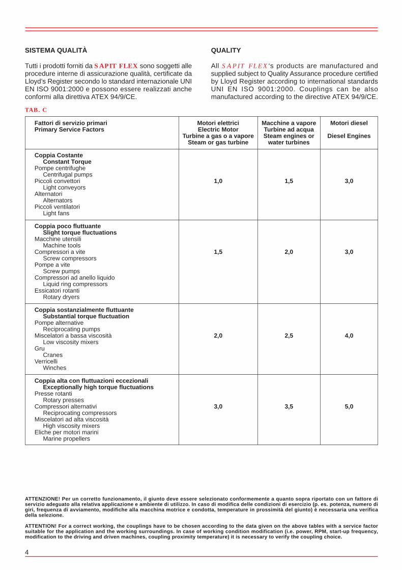
SISTEMA QUALITÀ
Tutti i prodotti forniti da SAPIT FLEX sono soggetti alleprocedure interne di assicurazione qualità, certificate daLloyd’s Register secondo lo standard internazionale UNIEN ISO 9001:2000 e possono essere realizzati ancheconformi alla direttiva ATEX 94/9/CE.
QUALITY
All SAPIT FLEX‘s products are manufactured andsupplied subject to Quality Assurance procedure certifiedby Lloyd Register according to international standardsUNI EN ISO 9001:2000. Couplings can be alsomanufactured according to the directive ATEX 94/9/CE.
Fattori di servizio primariPrimary Service Factors
Coppia Costante Constant TorquePompe centrifughe Centrifugal pumpsPiccoli convettori Light conveyorsAlternatori AlternatorsPiccoli ventilatori Light fans
Coppia poco fluttuante Slight torque fluctuationsMacchine utensili Machine toolsCompressori a vite Screw compressorsPompe a vite Screw pumpsCompressori ad anello liquido Liquid ring compressorsEssicatori rotanti Rotary dryers
Coppia sostanzialmente fluttuante Substantial torque fluctuationPompe alternative Reciprocating pumpsMiscelatori a bassa viscosità Low viscosity mixersGru CranesVerricelli Winches
Coppia alta con fluttuazioni eccezionali Exceptionally high torque fluctuationsPresse rotanti Rotary pressesCompressori alternativi Reciprocating compressorsMiscelatori ad alta viscosità High viscosity mixersEliche per motori marini Marine propellers
Motori elettriciElectric Motor
Turbine a gas o a vaporeSteam or gas turbine
Macchine a vaporeTurbine ad acquaSteam engines or
water turbines
Motori diesel
Diesel Engines
ATTENZIONE! Per un corretto funzionamento, il giunto deve essere selezionato conformemente a quanto sopra riportato con un fattore diservizio adeguato alla relativa applicazione e ambiente di utilizzo. In caso di modifica delle condizioni di esercizio (p. es. potenza, numero digiri, frequenza di avviamento, modifiche alla macchina motrice e condotta, temperature in prossimità del giunto) è necessaria una verificadella selezione.
ATTENTION! For a correct working, the couplings have to be chosen according to the data given on the above tables with a service factorsuitable for the application and the working surroundings. In case of working condition modification (i.e. power, RPM, start-up frequency,modification to the driving and driven machines, coupling proximity temperature) it is necessary to verify the coupling choice.
1,0
1,5
2,0
3,0
1,5
2,0
2,5
3,5
3,0
3,0
4,0
5,0
TAB. C

5
CARATTERISTICHE / FEATURESPotenza nominale trasmissibile =Nominal rating transmissible =HP/n 1’ 0,0014kw/n 1’ 0,0010
Coppia nominale trasmissione =Nominal torque =Nm; 10
Disassamento angolare max = 1° per elementoMax angular misalignment = 1° each element
Disassamento parallelo max =Max parallel misalignment =mm. 0,4
Deflessione assiale max =Max axial deflection =± mm. 1,5
Velocità ammissibile = 35000 giri/1’Max speed = 35000 RPM
Tipo EBS1 = Peso kg. 0,450 PD2 kgm2 0,00049Type EBS1 = Weight Kg. 0,450 inertia PD2 Kgm2 0,00049
Tipo EBS1R = Peso kg. 0,380 PD2 kgm2 0,00036Type EBS1R = Weight Kg. 0,380 inertia PD2 Kgm2 0,00036
Serie/RangesEBS1 - EBS1.R
MICROGIUNTIMICROCOUPLINGS
EBS1
EBS1.R

6
Serie/RangesHBSX-4
CON SPAZIATORE A 4 PERNIDa HP 0,003 a HP 0,7 a 1 GIRO/1’4 BOLTS WITH SPACERFrom HP 0,003 to HP 0,7 at 1 RPM
3-4
6-4
18-4
35-4
60-4
100-4
140-4
180-4
330-4
700-4
Potenza trasmis.a 1 giro/1’
Nominal ratingtransmissible at 1 RPM
TIPO
SIZE
Coppia tras.
Nominal Torque
Nm
20
40
130
250
420
700
1000
1300
2300
4900
HP/n
0,003
0,006
0,018
0,035
0,060
0,100
0,142
0,185
0,327
0,697
KW/n
0,002
0,004
0,013
0,026
0,044
0,074
0,105
0,136
0,241
0,513
TAB. A
38
51
68
81
89
115
132
151
170
180
M1
mm
33
46
61
72
82
105
118
137
156
168
M
mm
40
42
58
60
82
81
108
131
131
160
L3
mm
52
55
75
80
105
110
140
165
170
215
L2
mm
6
6,5
8,5
10
11,5
14,5
16
17
19,5
27,5
S
mm
25
40
50
60
70
90
100
115
130
140
L1
mm
26
35
48
55
63
80
94
105
120
125
d1max
mm
23
32
42
50
58
75
85
95
110
120
dmax
mm
13
13
13
17
17
17
20
20
20
20
d: d1min
mm
56
86,5
108,5
130
151,5
194,5
216
247
279,5
307,5
HBXL
mm
102
135
175
200
245
290
340
395
430
495
HBSXL
mm
67
81
104
126
143
168
194
214
246
275
D
mm
Disassamento angolare max = 1° per elementoMax angular misalignment = 1° each element
Disassamento parallelo max mm = 0.017 x (L3 + S)Max parallel misalignment = 0.017 x (L3 + S)
DIMENSIONI RIFERITE AI TIPI STANDARDPossono essere variate le dimensioni di lunghezza dei mozzie dello spaziatore
DIMENSIONS REFERRED TO STANDARD VERSIONHubs and spacer lengths can be modified
Serie/RangesHBX-4
SENZA SPAZIATORE A 4 PERNIDa HP 0,003 a HP 0,7 a 1 GIRO/1’4 BOLTS WITHOUT SPACERFrom HP 0,003 to HP 0,7 at 1 RPM
Disassamento angolare max = 1°Max angular misalignment = 1°
DIMENSIONI RIFERITE AI TIPI STANDARDPossono essere variate le dimensioni di lunghezza dei mozzi
DIMENSIONS REFERRED TO STANDARD VERSIONHubs and spacer lengths can be modified

TIPO DEL GIUNTOCOUPLING SIZE
Peso HBSX kg.Weight HBSX kg.
Peso HBX kg.Weight HBX kg.
PD2 HBSX kgm2
Inertia PD2 HBSX kgm2
PD2 HBX kgm2
Inertia PD2 HBX kgm2
Rigidità torsionale HBSX Nm/rad x 106
Torsional Stiffness HBSX Nm/rad x 106
Rigidità torsionale HBX Nm/rad x 106
Torsional Stiffness HBX Nm/rad x 106
Coppia di serraggio dadi pacchi lamellari NmNuts tightenning torque of element blades Nm
Deflessione assiale HBSX +/- mmAxial deflection HBSX +/- mm
Deflessione assiale HBX +/- mmAxial deflection HBX +/- mm
Velocità ammessa giri/1’Max speed RPM
7
TAB. B
700-4
96,5
71,0
2,8746
1,7697
3,2196
8,6897
500
10,0
5,0
6100
Caratteristiche tecniche / Technical featuresSerie/Ranges HBSX-4 • HBX-4
330-4
67,0
52,5
1,5355
1,0137
1,5647
3,5100
180
9,0
4,5
6300
180-4
45,5
35,5
0,7788
0,5180
0,8770
1,9532
80
8,0
4,0
8400
140-4
32,6
24,5
0,4741
0,2995
0,7112
1,5902
80
7,0
3,5
8500
100-4
21,6
16,6
0,2312
0,1497
0,5062
1,1154
45
6,0
3,0
10500
60-4
12,6
8,9
0,1024
0,0603
0,2943
0,6995
45
4,8
2,4
14000
35-4
8,3
5,9
0,0528
0,0315
0,1815
0,4228
23
4,2
2,1
14600
18-4
4,7
3,4
0,0196
0,0118
0,0932
0,2060
10
3,6
1,8
19500
6-4
2,3
1,6
0,0061
0,0036
0,0324
0,0706
5
2,8
1,4
27500
3-4
0,9
0,6
0,016
0,0009
0,1668
0,4611
5
2,0
1,0
30000
NOTE:A) I pesi e i PD2 sono calcolati con mozzi in acciaio, dimensioni a catalogo e con foro “d” min.B) La rigidità torsionale è data per dimensioni a catalogo e si riferisce ai particolari compresi tra le flange dei mozzi (spaziatore, pacchi lamellari, bulloneria, eventuali adattatori, ecc.).C) Il disassamento assiale ammissibile è in funzione del disassamento parallelo o viceversa.D) Prima di serrare i dadi che bloccano i pacchi lamellari è opportuno passare un velo d’olio sulle rispettive filettature.E) Le velocità massime ammesse (Giri/1’) sono calcolate con i componenti principali (mozzi, eventuali adattatori, spaziatori, ecc.) costruiti in acciaio al carbonio e con dimensioni a catalogo. Per velocità di esercizio superiori o sono usati acciai speciali o vengono eseguiti speciali studi.
Dati e dimensioni contenuti in questo catalogo possono essere variati senza preavviso.
NOTES:A) Weight and inertia are calculated with steel hubs, standard dimensions and with min bore “d”.B) Torsional stiffness is given between hub flanges for standard dimensions (spacer, elements blades, bolts, adaptors, etc.).C) Allowable axial misalignment is related to parallel misalignment and viceversa.D) Before bolts tightening to lock the element blades it is advisable to apply a light oil film on the related threads.E) Max speed (RPM) are calculated with the main components (hubs, adaptors, spacers, etc.) manufactured in carbon steel and with standard dimensions. For higher operational speeds alternative materials or special designs are available.
Figures and dimensions included in this catalogue may be varied without prior advice.

8
Serie/RangesGCSX-4
CON SPAZIATORE A 4 PERNIDa HP 0,009 a HP 0,8 a 1 GIRO/1’4 BOLTS WITH SPACERFrom HP 0,009 to HP 0,8 at 1 RPM
9-4
13-4
26-4
36-4
80-4
125-4
160-4
255-4
345-4
560-4
800-4
Potenza trasmis.a 1 giro/1’
Nominal ratingtransmissible at 1 RPM
TIPO
SIZE
Coppia tras.
Nominal Torque
Nm
60
90
180
250
560
900
1100
1800
2400
3900
5600
HP/n
0,009
0,013
0,026
0,036
0,080
0,128
0,157
0,256
0,342
0,555
0,797
KW/n
0,007
0,009
0,019
0,026
0,059
0,094
0,119
0,188
0,251
0,408
0,586
TAB. A
33
46
50
61
72
82
105
118
137
156
168
M
mm
40
42
49
58
60
82
81
108
131
131
160
L3
mm
55
56
65
75
83
105
108
139
163
169
214
L2
mm
7,5
7
8
8,5
11,5
11,5
13,5
15,5
16
19
27
S
mm
25
40
45
50
60
70
90
100
115
130
140
L1
mm
23
32
35
42
50
58
75
85
95
110
120
dmax
mm
13
13
13
13
17
17
17
20
20
20
20
dmin
mm
57,5
87
98
108,5
131,5
151,5
193,5
215,5
246
279
307
GCXL
mm
105
136
155
175
203
245
288
339
393
429
494
GCSXL
mm
67
81
93
104
126
143
168
194
214
246
275
D
mm
Disassamento angolare max = 1° per elementoMax angular misalignment = 1° each element
Disassamento parallelo max mm = 0.017 x (L3 + S)Max parallel misalignment = 0.017 x (L3 + S)
DIMENSIONI RIFERITE AI TIPI STANDARDPossono essere variate le dimensioni di lunghezza dei mozzie dello spaziatore
DIMENSIONS REFERRED TO STANDARD VERSIONHubs and spacer lengths can be modified
Serie/RangesGCX-4
SENZA SPAZIATORE A 4 PERNIDa HP 0,009 a HP 0,8 a 1 GIRO/1’4 BOLTS WITHOUT SPACERFrom HP 0,009 to HP 0,8 at 1 RPM
Disassamento angolare max = 1°Max angular misalignment = 1°
DIMENSIONI RIFERITE AI TIPI STANDARDPossono essere variate le dimensioni di lunghezza dei mozzi
DIMENSIONS REFERRED TO STANDARD VERSIONHubs and spacer lengths can be modified
41
MOZZO CON CALETTATORE
HUB WITH SHRINK DISCS
GIUNTO CON ISOLAMENTODA CORRENTI PARASSITE
COUPLING WITH PARASSITICCURRENT INSULATION
GIUNTO CON TORSIOMETRO
COUPLING WITH TORQUEMETER
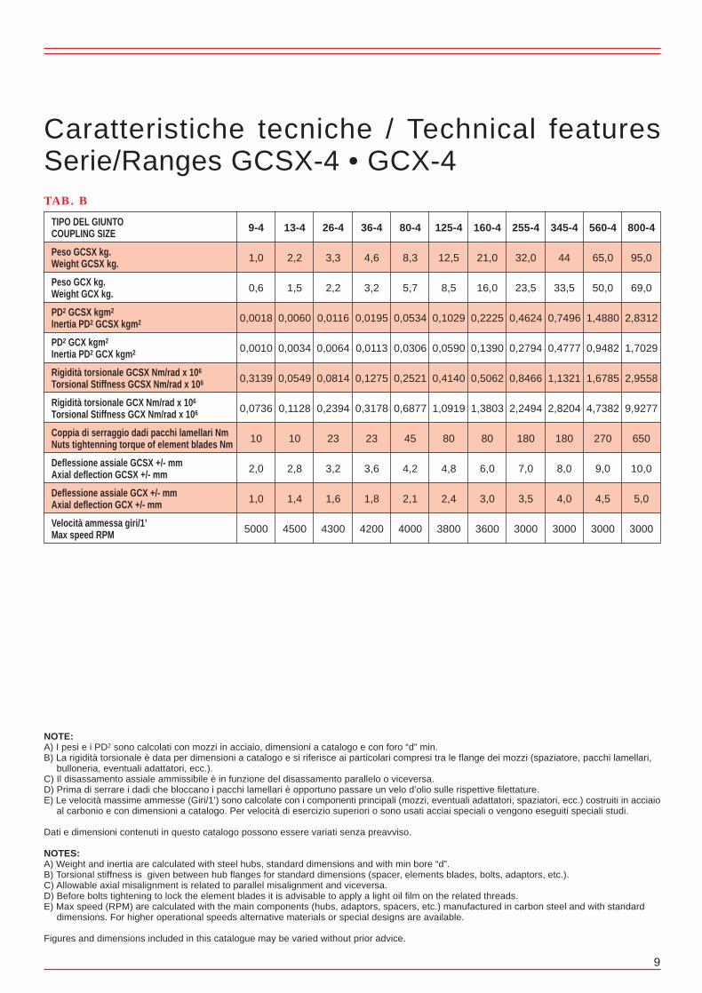
TIPO DEL GIUNTOCOUPLING SIZE
Peso GCSX kg.Weight GCSX kg.
Peso GCX kg.Weight GCX kg.
PD2 GCSX kgm2
Inertia PD2 GCSX kgm2
PD2 GCX kgm2
Inertia PD2 GCX kgm2
Rigidità torsionale GCSX Nm/rad x 106
Torsional Stiffness GCSX Nm/rad x 106
Rigidità torsionale GCX Nm/rad x 106
Torsional Stiffness GCX Nm/rad x 106
Coppia di serraggio dadi pacchi lamellari NmNuts tightenning torque of element blades Nm
Deflessione assiale GCSX +/- mmAxial deflection GCSX +/- mm
Deflessione assiale GCX +/- mmAxial deflection GCX +/- mm
Velocità ammessa giri/1’Max speed RPM
9
TAB. B
800-4
95,0
69,0
2,8312
1,7029
2,9558
9,9277
650
10,0
5,0
3000
Caratteristiche tecniche / Technical featuresSerie/Ranges GCSX-4 • GCX-4
560-4
65,0
50,0
1,4880
0,9482
1,6785
4,7382
270
9,0
4,5
3000
345-4
44
33,5
0,7496
0,4777
1,1321
2,8204
180
8,0
4,0
3000
255-4
32,0
23,5
0,4624
0,2794
0,8466
2,2494
180
7,0
3,5
3000
160-4
21,0
16,0
0,2225
0,1390
0,5062
1,3803
80
6,0
3,0
3600
125-4
12,5
8,5
0,1029
0,0590
0,4140
1,0919
80
4,8
2,4
3800
80-4
8,3
5,7
0,0534
0,0306
0,2521
0,6877
45
4,2
2,1
4000
36-4
4,6
3,2
0,0195
0,0113
0,1275
0,3178
23
3,6
1,8
4200
26-4
3,3
2,2
0,0116
0,0064
0,0814
0,2394
23
3,2
1,6
4300
13-4
2,2
1,5
0,0060
0,0034
0,0549
0,1128
10
2,8
1,4
4500
40
GIUNTO CON LAMELLE A SETTORI
COUPLING WITH SEGMENTALELEMENT BLADES
GIUNTO PER MONTAGGIO VERTICALE
COUPLING FOR VERTICAL ASSEMBLING
GIUNTO CON LIMITATORE ASSIALE
COUPLING WITH AXIAL MOVEMENTLIMITING DEVICE
9-4
1,0
0,6
0,0018
0,0010
0,3139
0,0736
10
2,0
1,0
5000
NOTE:A) I pesi e i PD2 sono calcolati con mozzi in acciaio, dimensioni a catalogo e con foro “d” min.B) La rigidità torsionale è data per dimensioni a catalogo e si riferisce ai particolari compresi tra le flange dei mozzi (spaziatore, pacchi lamellari, bulloneria, eventuali adattatori, ecc.).C) Il disassamento assiale ammissibile è in funzione del disassamento parallelo o viceversa.D) Prima di serrare i dadi che bloccano i pacchi lamellari è opportuno passare un velo d’olio sulle rispettive filettature.E) Le velocità massime ammesse (Giri/1’) sono calcolate con i componenti principali (mozzi, eventuali adattatori, spaziatori, ecc.) costruiti in acciaio al carbonio e con dimensioni a catalogo. Per velocità di esercizio superiori o sono usati acciai speciali o vengono eseguiti speciali studi.
Dati e dimensioni contenuti in questo catalogo possono essere variati senza preavviso.
NOTES:A) Weight and inertia are calculated with steel hubs, standard dimensions and with min bore “d”.B) Torsional stiffness is given between hub flanges for standard dimensions (spacer, elements blades, bolts, adaptors, etc.).C) Allowable axial misalignment is related to parallel misalignment and viceversa.D) Before bolts tightening to lock the element blades it is advisable to apply a light oil film on the related threads.E) Max speed (RPM) are calculated with the main components (hubs, adaptors, spacers, etc.) manufactured in carbon steel and with standard dimensions. For higher operational speeds alternative materials or special designs are available.
Figures and dimensions included in this catalogue may be varied without prior advice.
10
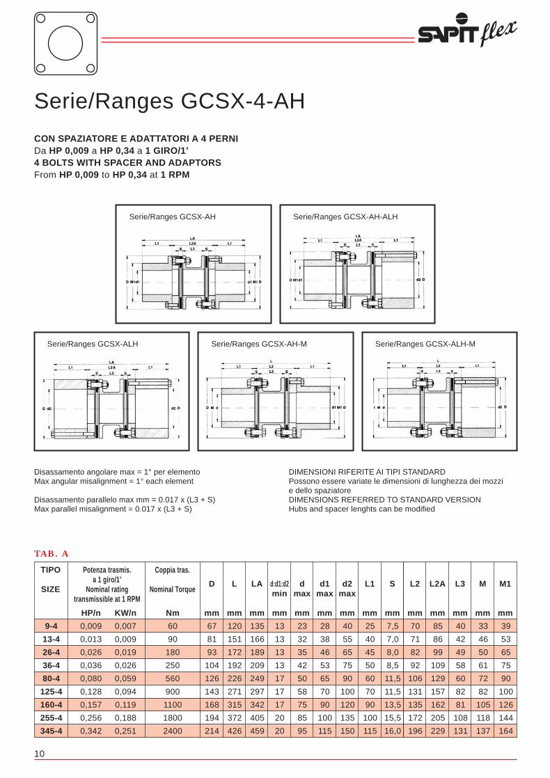
Serie/Ranges GCSX-4-AH
CON SPAZIATORE E ADATTATORI A 4 PERNIDa HP 0,009 a HP 0,34 a 1 GIRO/1’4 BOLTS WITH SPACER AND ADAPTORSFrom HP 0,009 to HP 0,34 at 1 RPM
9-4
13-4
26-4
36-4
80-4
125-4
160-4
255-4
345-4
Potenza trasmis.a 1 giro/1’
Nominal ratingtransmissible at 1 RPM
TIPO
SIZE
Coppia tras.
Nominal Torque
Nm
60
90
180
250
560
900
1100
1800
2400
HP/n
0,009
0,013
0,026
0,036
0,080
0,128
0,157
0,256
0,342
KW/n
0,007
0,009
0,019
0,026
0,059
0,094
0,119
0,188
0,251
TAB. A
70
71
82
92
106
131
135
172
196
L2
mm
7,5
7,0
8,0
8,5
11,5
11,5
13,5
15,5
16,0
S
mm
25
40
45
50
60
70
90
100
115
L1
mm
40
55
65
75
90
100
120
135
150
d2max
mm
28
38
46
53
65
70
90
100
115
d1max
mm
23
32
35
42
50
58
75
85
95
dmax
mm
13
13
13
13
17
17
17
20
20
d:d1:d2min
mm
135
166
189
209
249
297
342
405
459
LA
mm
120
151
172
192
226
271
315
372
426
L
mm
67
81
93
104
126
143
168
194
214
D
mm
39
GIUNTO CON ADATTATORE A CAMPANA
COUPLING WITH SLEEVE ADAPTER
GIUNTO SECONDO NORMATIVA API 610
COUPLING ACCORDING TOAPI 610 STANDARD
GIUNTO A MOMENTO RIDOTTOSECONDO NORMATIVA API 671
COUPLING WITH REDUCED MOMENTON STANDARD API 671
Disassamento angolare max = 1° per elementoMax angular misalignment = 1° each element
Disassamento parallelo max mm = 0.017 x (L3 + S)Max parallel misalignment = 0.017 x (L3 + S)
DIMENSIONI RIFERITE AI TIPI STANDARDPossono essere variate le dimensioni di lunghezza dei mozzie dello spaziatoreDIMENSIONS REFERRED TO STANDARD VERSIONHubs and spacer lenghts can be modified
85
86
99
109
129
157
162
205
229
L2A
mm
40
42
49
58
60
82
81
108
131
L3
mm
33
46
50
61
72
82
105
118
137
M
mm
39
53
65
75
90
100
126
144
164
M1
mm
Serie/Ranges GCSX-ALH Serie/Ranges GCSX-AH-M Serie/Ranges GCSX-ALH-M
Serie/Ranges GCSX-AH Serie/Ranges GCSX-AH-ALH

TIPO DEL GIUNTOCOUPLING SIZE
Peso GCSX-AH kg.Weight GCSX-AH kg.
Peso GCSX-AH-ALH kg.Weight GCSX-AH-ALH kg.
Peso GCSX-ALH kg.Weight GCSX-ALH kg.
Peso GCSX-AH-M kg.Weight GCSX-AH-M kg.
Peso GCSX-ALH-M kg.Weight GCSX-ALH-M kg.
PD2 GCSX-AH kgm2
Inertia PD2 GCSX-AH kgm2
PD2 GCSX-AH-ALH kgm2
Inertia PD2 GCSX-AH-ALH kgm2
PD2 GCSX-ALH kgm2
Inertia PD2 GCSX-ALH kgm2
PD2 GCSX-AH-M kgm2
Inertia PD2 GCSX-AH-M kgm2
PD2 GCSX-ALH-M kgm2
Inertia PD2 GCSX-ALH-M kgm2
Rigidità torsionale GCSX-AH • GCSX-AH-ALH • GCSX-ALH Nm/rad x 106
Torsional Stiffness GCSX-AH • GCSX-AH-ALH • GCSX-ALH Nm/rad x 106
Rigidità torsionale GCSX-AH-M • GCSX-ALH-M Nm/rad x 106
Torsional Stiffness GCSX-AH-M • GCSX-ALH-M Nm/rad x 106
Coppia di serraggio dadi pacchi lamellari NmNuts tightenning torque of element blades Nm
Coppia di serraggio bulloni adattatori NmNuts tightenning torque of adaptator Nm
Deflessione assiale +/- mmAxial deflection +/- mm
Velocità ammessa giri/1’Max speed RPM
11
TAB. B
345-4
66,0
54,0
65,0
88,0
77,0
1,4657
1,0363
2,1818
1,3230
1,7524
1,0546
1,1125
180
85
8,0
3000
Caratteristiche tecniche / Technical featuresSerie/Ranges GCSX-4-AH
255-4
49,0
40,0
66,0
48,0
57,0
0,9026
0,6406
1,3428
0,8188
1,0808
0,8388
0,8309
180
85
7,0
3000
160-4
32,0
26,0
43,0
31,0
27,0
0,4391
0,3064
0,6557
0,3903
0,5230
0,5023
0,4983
80
50
5,0
3600
125-4
19,5
15,7
26,5
19,0
22,6
0,1977
0,1450
0,2925
0,1717
0,2348
0,4091
0,4042
80
50
4,8
3800
80-4
13,0
10,6
17,8
13,0
15,4
0,1029
0,0738
0,1524
0,0942
0,1233
0,2492
0,2472
45
25
4,2
4000
36-4
7,2
5,8
9,8
7,1
8,5
0,0381
0,0268
0,0567
0,0341
0,0454
0,1265
0,1256
23
10
3,6
4200
26-4
5,4
4,3
7,4
5,3
6,4
0,0227
0,0162
0,0338
0,0208
0,0273
0,0804
0,0795
23
10
3,2
4300
13-4
3,6
2,8
4,9
3,3
4,1
0,0117
0,0082
0,0174
0,0104
0,0139
0,0549
0,0540
10
10
2,8
4500
9-4
1,7
1,4
2,5
1,8
2,1
0,0038
0,0028
0,0058
0,0038
0,0048
0,0314
0,0304
10
10
2
5000
38
GIUNTO CON ADATTATORE MAGGIORATO
COUPLING WITH OVERSIZED ADAPTER
Applicazioni speciali dei giunti lamellariSpecial applications of disc couplings
Questi sono alcuni esempi che illustrano applicazioni per cui vengono prodotti i giunti SAPIT FLEX.Naturalmente è possibile combinare varie soluzioni o modificare i modelli in modo da ottenererisultati idonei alle varie esigenze.Lo spazio non consente di includere tutte le innumerevoli applicazioni e, quindi, se un particolareadattamento non è illustrato ci si rivolga al nostro servizio tecnico che è a disposizione perqualsiasi necessità.
Here under are shown few examples of disc couplings commercialized by SAPIT FLEX forspecial applications.It is possible to combine different solutions or to modify the types in order to comply with theend user requirements.Many other special disc couplings applications are regularly commercialized by SAPIT FLEXwhich for space reason are not shown in this catalogue. For any information and assistanceplease refer to our technical service.
NOTE:A) I pesi e i PD2 sono calcolati con mozzi in acciaio, dimensioni a catalogo e con foro “d” min.B) La rigidità torsionale è data per dimensioni a catalogo e si riferisce ai particolari compresi tra le flange dei mozzi (spaziatore, pacchi lamellari, bulloneria, eventuali adattatori, ecc.).C) Il disassamento assiale ammissibile è in funzione del disassamento parallelo o viceversa.D) Prima di serrare i dadi che bloccano i pacchi lamellari è opportuno passare un velo d’olio sulle rispettive filettature.E) Le velocità massime ammesse (Giri/1’) sono calcolate con i componenti principali (mozzi, eventuali adattatori, spaziatori, ecc.) costruiti in acciaio al carbonio e con dimensioni a catalogo. Per velocità di esercizio superiori o sono usati acciai speciali o vengono eseguiti speciali studi.
Dati e dimensioni contenuti in questo catalogo possono essere variati senza preavviso.
NOTES:A) Weight and inertia are calculated with steel hubs, standard dimensions and with min bore “d”.B) Torsional stiffness is given between hub flanges for standard dimensions (spacer, elements blades, bolts, adaptors, etc.).C) Allowable axial misalignment is related to parallel misalignment and viceversa.D) Before bolts tightening to lock the element blades it is advisable to apply a light oil film on the related threads.E) Max speed (RPM) are calculated with the main components (hubs, adaptors, spacers, etc.) manufactured in carbon steel and with standard dimensions. For higher operational speeds alternative materials or special designs are available.
Figures and dimensions included in this catalogue may be varied without prior advice.

Assembling procedure of disc packs
A) All SAPIT FLEX‘s couplings have, as a peculiarity, (except the series RH) the possibility to change the flexible elements and eventual centre spacers without moving the connected machines.
B) Examples of disc pack assembling and disassembling of the coupling series HBX - HBSX - HBSX/AH - HBSX/RH - HPX - HPSX - BE
Figure 1 = Disc pack assembling diagramFigure 1a = Short bolt disc pack assembling diagram, coupling series HBSX/AHFigure 1b = Short bolt disc pack assembling diagram, coupling series HBSX/RH
C) Examples of disc pack assembling and disassembling of the coupling series GCX - GCSX - GCSX/AH - GCSTX - GCSTX/CTFX - GCSTX/FC
Figure 2 = Disc pack assembling diagramFigure 2a = Disc pack assembling diagram, coupling series GCSX/AHFigure 2b = Disc pack assembling diagram, with tie rod
12
Serie/RangesGCSTX-4
CON SPAZIATORE COMPOSTO IN ACCIAIODa HP 0,08 a HP 0,8 a 1 GIRO/1’WITH COMBINED SPACER IN STEELFrom HP 0,08 to HP 0,8 at 1 RPM
80-4
125-4
160-4
255-4
345-4
560-4
800-4
Potenza trasmis.a 1 giro/1’
Nominal ratingtransmissible at 1 RPM
TIPO
SIZE
Coppia tras.
Nominal Torque
Nm
560
900
1100
1800
2400
3900
5600
HP/n
0,080
0,128
0,157
0,256
0,342
0,555
0,797
KW/n
0,059
0,094
0,119
0,188
0,251
0,408
0,586
TAB. A
72
82
105
118
137
156
168
M
mm
1957
2467
2468
2809
3148
3142
3126
L3
mm
1980
2490
2495
2840
3180
3180
3180
L2
mm
11,5
11,5
13,5
15,5
16
19
27
S
mm
60
70
90
100
115
130
140
L1
mm
50
58
75
85
95
110
120
dmax
mm
17
17
17
20
20
20
20
dmin
mm
2100
2630
2675
3040
3410
3440
3460
L
mm
126
143
168
194
214
246
275
D
mm
Disassamento angolare max = 1° per elementoMax angular misalignment = 1° each element
Disassamento parallelo max mm = 0.017 x (L3 + S)Max parallel misalignment = 0.017 x (L3 + S)
DIMENSIONI RIFERITE AI TIPI STANDARDPossono essere variate le dimensioni di lunghezza dei mozzi e dello spaziatore
DIMENSIONS REFERRED TO STANDARD VERSIONHubs and spacer lenghts can be modified
* Dimensioni ammesse per velocità di esercizionon superiori a 1500 giri/1’* Allowable dimensions for operational speedsnot higher than 1500 RPM
37
Figure 2 Figure 2a Figure 2b
Figure 1 Figure 1a Figure 1b
TIPO DEL GIUNTOCOUPLING SIZE
Peso GCSTX-4 kg.Weight GCSTX-4 kg.
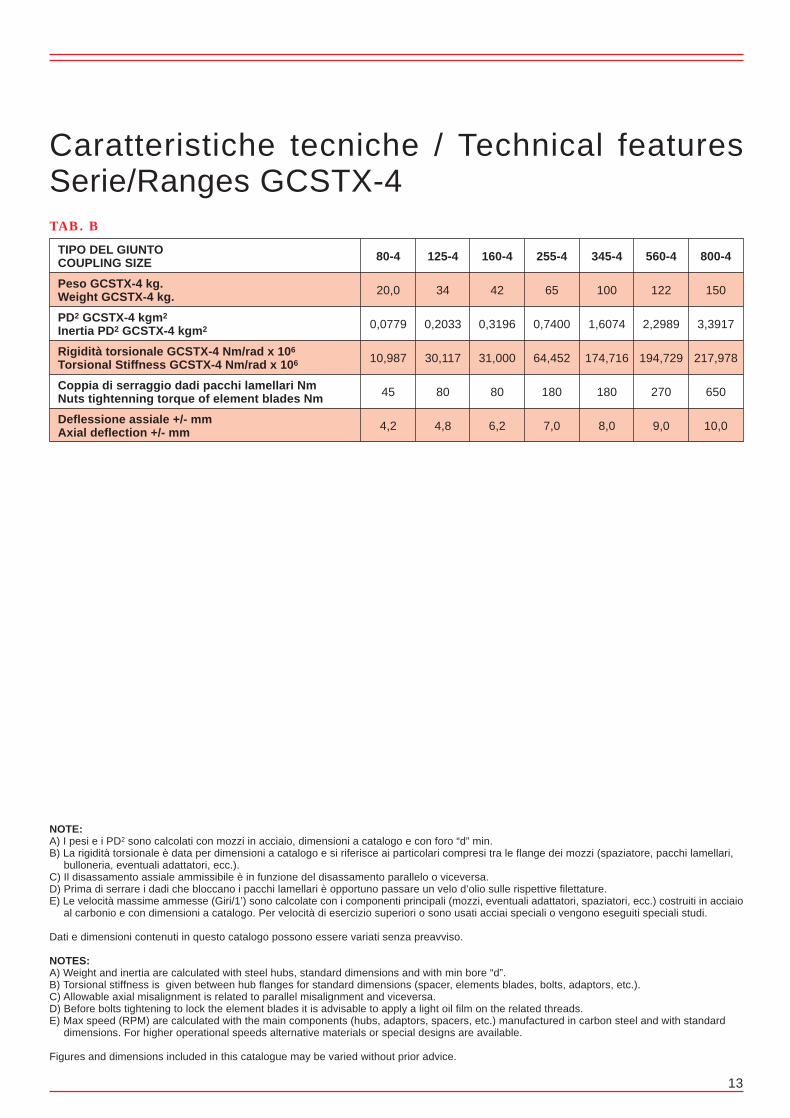
PD2 GCSTX-4 kgm2
Inertia PD2 GCSTX-4 kgm2
Rigidità torsionale GCSTX-4 Nm/rad x 106
Torsional Stiffness GCSTX-4 Nm/rad x 106
Coppia di serraggio dadi pacchi lamellari NmNuts tightenning torque of element blades Nm
Deflessione assiale +/- mmAxial deflection +/- mm
13
TAB. B
800-4
150
3,3917
217,978
650
10,0
Caratteristiche tecniche / Technical featuresSerie/Ranges GCSTX-4
560-4
122
2,2989
194,729
270
9,0
345-4
100
1,6074
174,716
180
8,0
255-4
65
0,7400
64,452
180
7,0
160-4
42
0,3196
31,000
80
6,2
125-4
34
0,2033
30,117
80
4,8
80-4
20,0
0,0779
10,987
45
4,2
36
The values Smax - Smin must be ≤ of ∆pα (mm):For 4 bolts coupling of ∆pα (mm) = [α (rad) x D] where α (rad) = 0.004 mmFor 6 bolts coupling of ∆pα (mm) = [α (rad) x D] where α (rad) = 0.003 mmFor 8 bolts coupling of ∆pα (mm) = [α (rad) x D] where α (rad) = 0.002 mmFor 10 bolts coupling of ∆pα (mm) = [α (rad) x D] where α (rad) = 0.0015 mmFor 12 bolts coupling of ∆pα (mm) = [α (rad) x D] where α (rad) = 0.001 mm
Then:Parallel alignment ∆p (mm) ≤ (rad) x LaAngular alignment ∆α (mm) ≤ (rad) x D
The stated values are for general use and can vary in specific cases, for instance for couplings working at high dilatationsor speeds.
In any case, better is the initial alignment, higher is the tolerance at unforeseen misalignment due to structuremovements.
After having properly aligned the coupling, make sure that all the bolts or fixing screws are tightened. If possible checkthe tightening after some hours of operation too.
BALANCING
Usually during balancing on flanges, of couplings for medium and high speeds, are printed some references (e.g.alphabetic letters) to be respected when assembling.For making easier the precision balancing on site we foresee some tapped hole on flanges in order to have the possibilityto add balancing weights.
NOTE:A) I pesi e i PD2 sono calcolati con mozzi in acciaio, dimensioni a catalogo e con foro “d” min.B) La rigidità torsionale è data per dimensioni a catalogo e si riferisce ai particolari compresi tra le flange dei mozzi (spaziatore, pacchi lamellari, bulloneria, eventuali adattatori, ecc.).C) Il disassamento assiale ammissibile è in funzione del disassamento parallelo o viceversa.D) Prima di serrare i dadi che bloccano i pacchi lamellari è opportuno passare un velo d’olio sulle rispettive filettature.E) Le velocità massime ammesse (Giri/1’) sono calcolate con i componenti principali (mozzi, eventuali adattatori, spaziatori, ecc.) costruiti in acciaio al carbonio e con dimensioni a catalogo. Per velocità di esercizio superiori o sono usati acciai speciali o vengono eseguiti speciali studi.
Dati e dimensioni contenuti in questo catalogo possono essere variati senza preavviso.
NOTES:A) Weight and inertia are calculated with steel hubs, standard dimensions and with min bore “d”.B) Torsional stiffness is given between hub flanges for standard dimensions (spacer, elements blades, bolts, adaptors, etc.).C) Allowable axial misalignment is related to parallel misalignment and viceversa.D) Before bolts tightening to lock the element blades it is advisable to apply a light oil film on the related threads.E) Max speed (RPM) are calculated with the main components (hubs, adaptors, spacers, etc.) manufactured in carbon steel and with standard dimensions. For higher operational speeds alternative materials or special designs are available.
Figures and dimensions included in this catalogue may be varied without prior advice.
∆α (mm) = Smax - Smin
∆α (rad) = Smax - Smin D

14
Serie/RangesGCSX/CTFX-4
CON SPAZIATORE COMPOSTO IN ACCIAIO E SUPPORTO CENTRALEDa HP 0,08 a HP 0,8 a 1 GIRO/1’WITH COMBINED SPACER IN STEEL AND CENTRAL BEARINGFrom HP 0,08 to HP 0,8 at 1 RPM
Disassamento angolare max = 1° per elementoMax angular misalignment = 1° each element
Disassamento parallelo max mm = 0.017 x (L - S)Max parallel misalignment = 0.017 x (L - S)
DIMENSIONI RIFERITE AI TIPI STANDARD - Possono essere variate le dimensioni di lunghezza dei mozzi e dello spaziatoreDIMENSIONS REFERRED TO STANDARD VERSION - Hubs and spacer lenghts can be modified
* Dimensioni ammesse per velocità di esercizionon superiori a 1500 giri/1’* Allowable dimensions for operational speedsnot higher than 1500 RPM
35
80-4
125-4
160-4
255-4
345-4
560-4
800-4
Potenza trasmis.a 1 giro/1’
Nominal ratingtransmissible at 1 RPM
TIPO
SIZE
Coppia tras.
Nominal Torque
Nm
560
900
1100
1800
2400
3900
5600
HP/n
0,080
0,128
0,157
0,256
0,342
0,555
0,797
KW/n
0,059
0,094
0,119
0,188
0,251
0,408
0,586
TAB. A
72
82
105
118
137
156
168
M
mm
2100
2625
2640
2990
3335
3385
3385
L5
mm
120
130
150
170
180
220
235
L4
mm
1957
2467
2468
2809
3148
3142
3126
L3
mm
1980
2490
2495
2840
3180
3180
3180
L2
mm
11,5
11,5
13,5
15,5
16
19
27
S
mm
60
70
85
100
115
130
140
L1
mm
50
58
75
85
95
110
120
dmax
mm
17
17
17
20
20
20
20
dmin
mm
4200
5245
5395
6000
6695
6785
6800
L
mm
126
143
168
194
214
246
275
D
mm
80-4
125-4
160-4
255-4
345-4
560-4
800-4
Supporto S.K.F. completoComplete S.K.F. bearing
TIPOTYPE
27
30
30
32
32
40
45
Rmm
16 M
16 M
16 M
20 M
20 M
24 M
24 M
Ømm
210
210
230
260
260
320
350
Fmm
70
70
80
95
95
112
125
Hmm
50
55
60
70
75
90
100
d1mm
SNH 511 TA + 1211 K + H 211
SNH 512 TA + 1212 K + H 212
SNH 513 TA + 1213 K + H 213
SNH 516 TA + 1216 K + H 216
SNH 517 TA + 1217 K + H 217
SNH 520 TA + 1220 K + H 220
SNH 522 TA + 1222 K + H 222
SAPIT FLEX disc coupling assembling andalignment instructions
SAPIT FLEX disc couplings tolerate misalignments which vary with the number of disc pack bolts. A 4 bolts couplings,for instance, allows a max angular misalignment of 1° corresponding to 0,017 mm per mm (rad), value that, multipliedby the distance between the disc packs or by the coupling outer diameter, give the value of the max parallel and angularmisalignment in mm.Those maximum figures are not intended to be used for initial alignment, because the allowable parallel misalignmentunder working condition will vary according to the axial deflection and viceversa. Both those values will vary with thespeed variation.Therefore it is important that initial alignment is as right as possible, in order to allow variations of conditions duringoperation.
COUPLING ASSEMBLING
Hubs have to be assembled on machine shafts so that the hub flange faces are aligned with shaft ends, except in caseof different instruction. The length of spacer complete of disc packs, and eventual adapters, will be then equal to thedistance between shaft ends (DBSE).The hubs with bores foreseen for low interference fit have to be uniformly heated at max 120-130°C and quicklyassembled on shafts. Do not heat locally in order to avoid stresses and permanent distorsions.The couplings with adapters are assembled with centring calibrated steps; for assembling and disassembling the centralpart it is necessary to press the same in order to get over the step. For small/medium size coupling disassembling itis sufficient to insert a screwdriver between the adapter and the hub flange, taking care not damage the connectionsurfaces meanwhile for big size couplings, on the flanges are foreseen tapped holes for pressing bolts.When assembling disc pack of the series GC, that have loose sleeves, it is important that the rounded surfaces of thesame are in the disc pack side. The higher sleeves have to be assembled into the flange large through holes.When utilising the coupling type GCSX/CTFX on cooling towers or on long spacer drive, we recommend to start thealignment procedure from the end hubs, considering for alignment the values given by SAPIT FLEX, setting up beforethe spacer shaft with support and then the other parts.
ALIGNMENT PROCEDURE
The alignment procedure will vary according to the involved machinery.Then we are not proposing to give operation details, but to propose misalignment limits and suggest the ways forchecking the same.
AXIAL ALIGNMENT
Generally, lower is the number of coupling disc pack bolts, higher is the allowed tolerance during initial alignment.We advice to respect the following limits, unless different specific instruction are given.The distance between hub flanges (L2) must be than:
For 4 bolts coupling ∆a = ± 1 mmFor 6 bolts coupling ∆a = ± 0,8 mmFor 8 bolts coupling ∆a = ± 0,5 mmFor 10 bolts coupling ∆a = ± 0,5 mmFor 12 bolts coupling ∆a = ± 0,5 mm
PARALLEL AND ANGULAR ALIGNMENT
We have three ways for checking the parallel and angular alignment.The most used is the classic one with the dial gauge, supported by the more innovative one with laser system.The more practical way consists in checking the gap between flanges, on both disc packs, on 360°; that is possible ifall coupling components are assembled.This method can be used also to verify the coupling alignment time going, without removing the transmission components.With this last procedure we check simultaneously the parallel ∆p and angular ∆α alignments.Check flange gap at 12 and 16 o’clock position (check of parallel and vertical angular alignment)Check flange gap at 9 and 3 o’clock position (check of parallel and horizontal angular alignment)

Procedura di montaggio pacchi lamellari
A) Tutti i giunti SAPIT FLEX hanno, come peculiarità, ma ad eccezione della serie RH, la possibilità di sostituire gli elementi flessibili ed eventuali spaziatori centrali senza rimuovere le macchine accoppiate.
B) Esempi di montaggio e smontaggio pacchi lamellari giunti serie HBX - HBSX - HBSX/AH - HBSX/RH - HPX - HPSX - BE
Figura 1 = Schema di montaggio pacco lamellareFigura 1a = Schema di montaggio pacco lamellare con bullone corto, giunti serie HBSX/AHFigura 1b = Schema di montaggio pacco lamellare con bullone corto, giunti serie HBSX/RH
C) Esempi di montaggio e smontaggio pacchi lamellari giunti serie GCX - GCSX - GCSX/AH - GCSTX - GCSTX/CTFX - GCSTX/FC
Figura 2 = Schema di montaggio pacco lamellareFigura 2a = Schema di montaggio pacco lamellare giunti serie GCSX/AHFigura 2b = Schema di montaggio pacco lamellare con tirante
TIPO DEL GIUNTOCOUPLING SIZE
Peso GCSX/CTFX-4 kg.Weight GCSX/CTFX-4 kg.
PD2 GCSX/CTFX-4 kgm2
Inertia PD2 GCSX/CTFX-4 kgm2
Rigidità torsionale GCSX/CTFX-4 Nm/rad x 106
Torsional Stiffness GCSX/CTFX-4XNm/rad x 106
Coppia di serraggio dadi pacchi lamellari NmNuts tightenning torque of element blades Nm
Deflessione assiale +/- mmAxial deflection +/- mm
15
TAB. B
800-4
217
5,5667
103,986
650
15
Caratteristiche tecniche / Technical featuresSerie/Ranges GCSX/CTFX-4
560-4
172
3,1226
98,689
270
13,5
345-4
134
2,0430
91,429
180
12,0
255-4
88
0,9927
31,784
180
10,5
160-4
57
0,4387
15,078
80
9,3
125-4
44
0,2620
14,833
80
7,2
80-4
26
0,1051
5,386
45
6,3
34
Figura 2 Figura 2a Figura 2b
Figura 1 Figura 1a Figura 1b
NOTE:A) I pesi e i PD2 sono calcolati con mozzi in acciaio, dimensioni a catalogo e con foro “d” min.B) La rigidità torsionale è data per dimensioni a catalogo e si riferisce ai particolari compresi tra le flange dei mozzi (spaziatore, pacchi lamellari, bulloneria, eventuali adattatori, ecc.).C) Il disassamento assiale ammissibile è in funzione del disassamento parallelo o viceversa.D) Prima di serrare i dadi che bloccano i pacchi lamellari è opportuno passare un velo d’olio sulle rispettive filettature.E) Le velocità massime ammesse (Giri/1’) sono calcolate con i componenti principali (mozzi, eventuali adattatori, spaziatori, ecc.) costruiti in acciaio al carbonio e con dimensioni a catalogo. Per velocità di esercizio superiori o sono usati acciai speciali o vengono eseguiti speciali studi.
Dati e dimensioni contenuti in questo catalogo possono essere variati senza preavviso.
NOTES:A) Weight and inertia are calculated with steel hubs, standard dimensions and with min bore “d”.B) Torsional stiffness is given between hub flanges for standard dimensions (spacer, elements blades, bolts, adaptors, etc.).C) Allowable axial misalignment is related to parallel misalignment and viceversa.D) Before bolts tightening to lock the element blades it is advisable to apply a light oil film on the related threads.E) Max speed (RPM) are calculated with the main components (hubs, adaptors, spacers, etc.) manufactured in carbon steel and with standard dimensions. For higher operational speeds alternative materials or special designs are available.
Figures and dimensions included in this catalogue may be varied without prior advice.
16
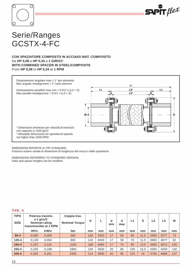
Serie/RangesGCSTX-4-FC
CON SPAZIATORE COMPOSTO IN ACCIAIO/ MAT. COMPOSITODa HP 0,08 a HP 0,34 a 1 GIRO/1’WITH COMBINED SPACER IN STEEL/COMPOSITEFrom HP 0,08 to HP 0,34 at 1 RPM
Disassamento angolare max = 1° per elementoMax angular misalignment = 1° each element
Disassamento parallelo max mm = 0.017 x (L3 + S)Max parallel misalignment = 0.017 x (L3 + S)
DIMENSIONI RIFERITE AI TIPI STANDARDPossono essere variate le dimensioni di lunghezza dei mozzi e dello spaziatore
DIMENSIONS REFERRED TO STANDARD VERSIONHubs and spacer lengths can be modified
* Dimensioni ammesse per velocità di esercizionon superiori a 1500 giri/1’* Allowable dimensions for operational speedsnot higher than 1500 RPM
33
80-4
125-4
160-4
255-4
345-4
Potenza trasmis.a 1 giro/1’
Nominal ratingtransmissible at 1 RPM
TIPO
SIZE
Coppia tras.
Nominal Torque
Nm
560
900
1100
1800
2400
HP/n
0,080
0,128
0,157
0,256
0,342
KW/n
0,059
0,094
0,119
0,188
0,251
TAB. A
72
82
105
118
137
M
mm
3277
3877
3873
4269
4668
L3
mm
3300
3900
3900
4300
4700
L2
mm
11,5
11,5
13,5
15,5
16
S
mm
60
70
90
100
115
L1
mm
50
58
75
85
95
dmax
mm
17
17
17
20
20
dmin
mm
3420
4040
4080
4500
4930
L
mm
126
143
168
194
214
D
mm
Controllo apertura flange a ore 12 e ore 6 (verifica allineamento parallelo e angolare verticale).Controllo apertura flange a ore 9 e ore 3 (verifica allineamento parallelo e angolare orizzontale).Il valore Smax - Smin deve essere ≤ di ∆pα (mm):
Per giunto a 4 perni di ∆pα (mm) = [α (rad) x D] dove α (rad) = 0.004Per giunto a 6 perni di ∆pα (mm) = [α (rad) x D] dove α (rad) = 0.003Per giunto a 8 perni di ∆pα (mm) = [α (rad) x D] dove α (rad) = 0.002Per giunto a 10 perni di ∆pα (mm) = [α (rad) x D] dove α (rad) = 0.0015Per giunto a 12 perni di ∆pα (mm) = [α (rad) x D] dove α (rad) = 0.001
Quindi:Allineamento parallelo ∆p (mm) ≤ α (rad) x LaAllineamento angolare ∆α (mm) ≤ α (rad) x D
I valori riportati sono per uso generale e possono variare in casi specifici, per esempio giunti sottoposti a elevatedilatazioni o per alte velocità.
In tutti i casi, migliore è l’allineamento iniziale, maggiore sarà la tolleranza per imprevisti disallineamenti dovutia movimenti strutturali.
Dopo aver correttamente allineato il giunto, assicurarsi che tutti i perni o viti di fissaggio siano serrati. Se possibile,controllare il serraggio dopo alcune ore di lavoro.
BILANCIATURA
Normalmente durante la bilanciatura sulle flange dei giunti per medie ed alte velocità, vengono incisi dei riferimenti(come lettere dell’alfabeto) che devono essere rispettati durante la fase di montaggio. Come facilitazione al bilanciamentodi precisione in loco, sono previsti fori filettati sulle flange per poter aggiungere pesi di bilanciamento.
∆α (mm) = Smax - Smin
∆α (rad) = Smax - Smin D

TIPO DEL GIUNTOCOUPLING SIZE
Peso GCSTX-4-FC kg.Weight GCSTX-4-FC kg.
PD2 GCSTX-4-FC kgm2
Inertia PD2 GCSTX-4-FC kgm2
Coppia di serraggio dadi pacchi lamellari NmNuts tightenning torque of element blades Nm
Deflessione assiale +/- mmAxial deflection +/- mm
17
TAB. B
Caratteristiche tecniche / Technical featuresSerie/Ranges GCSTX-4-FC
345-4
60
1,227
180
8,0
255-4
45
0,714
180
7,0
160-4
30
0,340
80
6,2
125-4
22
0,220
80
4,8
80-4
14,5
0,095
45
4,2
32
Istruzioni di installazione e allineamentodei giunti lamellari SAPIT FLEXI giunti lamellari SAPIT FLEX tollerano disassamenti che cambiano con il variare del numero dei perni del paccolamellare. Un giunto a 4 perni, per esempio, consente in esercizio un disassamento angolare max di 1°, corrispondentea 0.017 mm per mm (rad), valore che, moltiplicato per la distanza tra i pacchi lamellari o per il diametro esterno delgiunto, dà il valore corrispondente al max disassamento parallelo ed angolare in mm.Questi valori max di esercizio non sono validi per essere usati in fase di allineamento, perché il disassamento paralleloammesso in condizioni di esercizio, varierà in rapporto alla deflessione assiale e viceversa. Entrambi questi valoricambieranno con il variare della velocità. È quindi importante che l’allineamento iniziale risulti il più preciso possibile,in modo da consentire variazioni di condizioni durante l’esercizio.
INSTALLAZIONE DEL GIUNTO
I mozzi devono essere installati in modo che le teste degli assi siano a filo delle facce delle flange, a meno che nonci siano istruzioni diverse. La dimensione dello spaziatore completo di pacchi lamellari ed eventuali adattatori, sarà,quindi, uguale alla distanza tra le teste degli assi.I mozzi forati per accoppiamento con leggera interferenza, devono essere riscaldati uniformemente a max 120°÷130°Ce rapidamente posizionati sugli assi. Non riscaldare mai localmente, per evitare tensioni e deformazioni permanenti.I giunti con adattatori sono fissati ai mozzi con centraggi calibrati; per montare o smontare la parte centrale del giuntoè necessario che la stessa venga compressa quanto basta per superare i centraggi. Per lo smontaggio l’operazionepuò essere fatta, su giunti di piccole/medie dimensioni, inserendo un cacciavite tra l’adattatore e la flangia del mozzo,avendo cura di non danneggiare le superfici di accoppiamento; mentre, per giunti di grandi dimensioni, con l’ausiliodi fori per viti di compressione sulle flange.Quando si montano i pacchi lamellari della serie GC, che hanno bussole separate, è importante che le facce arrotondatedelle stesse siano verso il pacco lamellare. Le bussole più alte devono essere montate attraverso i fori grandi passantidelle flange.Quando si usano giunti del tipo GCSX/CTFX sulle torri di raffreddamento o su comandi a distanza, si raccomanda chela procedura di allineamento inizi dai mozzi terminali, adottando per l’allineamento i valori prescritti dalla SAPIT FLEX,aggiustando prima l’allunga con il supporto, poi l’altra.
PROCEDURE DI ALLINEAMENTO
La procedura di allineamento varierà a secondo del tipo di macchinario. Non ci si propone quindi di entrare nel dettaglioin riferimento al metodo di allineamento, ma, piuttosto, di proporre limiti di disallineamento e di indicare i modi con cuiquesti possono essere controllati.
ALLINEAMENTO ASSIALE
In generale, minore è il numero dei perni del pacco lamellare del giunto, maggiore sarà la tolleranza consentitanell’allineamento iniziale.Si consiglia che i seguenti limiti siano rispettati, a meno che siano date istruzioni specifiche. La distanza tra le flangedei mozzi (L2) deve essere ≤ di:
Per giunto a 4 perni ∆a = ± 1 mmPer giunto a 6 perni ∆a = ± 0,8 mmPer giunto a 8 perni ∆a = ± 0,5 mmPer giunto a 10 perni ∆a = ± 0,5 mmPer giunto a 12 perni ∆a = ± 0,5 mm
ALLINEAMENTO PARALLELO E ANGOLARE
Esistono sostanzialmente tre modi per controllare l’allineamento parallelo e angolare.Il più usato è quello classico del comparatore, affiancato dal più innovativo con sistema laser. Il terzo, più pratico,consiste nel controllare l’apertura delle flange sui 360° per ogni pacco lamellare; questo è possibile solo se tutta lacomponentistica del giunto è montata. Questo sistema può essere utilizzato anche per verificare l’allineamento delgiunto nel tempo, senza dover rimuovere i componenti delle trasmissioni.Con quest’ultima procedura, si controlla simultaneamente l’allineamento parallelo ∆p e angolare ∆α.
NOTE:A) I pesi e i PD2 sono calcolati con mozzi in acciaio, dimensioni a catalogo e con foro “d” min.B) La rigidità torsionale è data per dimensioni a catalogo e si riferisce ai particolari compresi tra le flange dei mozzi (spaziatore, pacchi lamellari, bulloneria, eventuali adattatori, ecc.).C) Il disassamento assiale ammissibile è in funzione del disassamento parallelo o viceversa.D) Prima di serrare i dadi che bloccano i pacchi lamellari è opportuno passare un velo d’olio sulle rispettive filettature.E) Le velocità massime ammesse (Giri/1’) sono calcolate con i componenti principali (mozzi, eventuali adattatori, spaziatori, ecc.) costruiti in acciaio al carbonio e con dimensioni a catalogo. Per velocità di esercizio superiori o sono usati acciai speciali o vengono eseguiti speciali studi.
Dati e dimensioni contenuti in questo catalogo possono essere variati senza preavviso.
NOTES:A) Weight and inertia are calculated with steel hubs, standard dimensions and with min bore “d”.B) Torsional stiffness is given between hub flanges for standard dimensions (spacer, elements blades, bolts, adaptors, etc.).C) Allowable axial misalignment is related to parallel misalignment and viceversa.D) Before bolts tightening to lock the element blades it is advisable to apply a light oil film on the related threads.E) Max speed (RPM) are calculated with the main components (hubs, adaptors, spacers, etc.) manufactured in carbon steel and with standard dimensions. For higher operational speeds alternative materials or special designs are available.
Figures and dimensions included in this catalogue may be varied without prior advice.

18
Serie/RangesHPSX-6
CON SPAZIATORE A 6 PERNIDa HP 40,08 a HP 1,3 a 1 GIRO/1’6 BOLTS WITH SPACERFrom HP 40,08 to HP 1,3 at 1 RPM
80-6
130-6
240-6
470-6
860-6
130-6
Potenza trasmis.a 1 giro/1’
Nominal ratingtransmissible at 1 RPM
TIPO
SIZE
Coppia tras.
Nominal Torque
Nm
560
900
1700
3300
6000
9100
HP/n
0,080
0,128
0,242
0,470
0,854
1,295
KW/n
0,059
0,094
0,178
0,345
0,628
0,952
TAB. A
74
81
97
104
124
143
M
mm
44
53
67
83
89
97
L3
mm
65
75
90
110
120
130
L2
mm
10,5
11,0
11,5
13,5
15,5
16,5
S
mm
55
65
75
80
95
110
L1
mm
52
56
68
72
85
100
dmax
mm
17
17
17
20
20
20
dmin
mm
120,5
141
161,5
173,5
205,5
236,5
HPXL
mm
175
205
240
270
310
350
HPSXL
mm
119
137
161
180
212
244
D
mm
Disassamento angolare max = 0° 45’ per elementoMax angular misalignment = 0° 45’ each element
Disassamento parallelo max mm = 0.012 x (L3 + S)Max parallel misalignment = 0.012 x (L3 + S)
DIMENSIONI RIFERITE AI TIPI STANDARDPossono essere variate le dimensioni di lunghezza dei mozzie dello spaziatore
DIMENSIONS REFERRED TO STANDARD VERSIONHubs and spacer length can be modified
Serie/RangesHPX-6
SENZA SPAZIATORE A 6 PERNIDa HP 40,08 a HP 1,3 a 1 GIRO/1’6 BOLTS WITHOUT SPACERFrom HP 40,08 to HP 1,3 at 1 RPM
Disassamento angolare max = 0° 45’Max angular misalignment = 0° 45’
DIMENSIONI RIFERITE AI TIPI STANDARDPossono essere variate le dimensioni di lunghezza dei mozzi
DIMENSIONS REFERRED TO STANDARD VERSIONHubs and spacer length can be modified
31
Serie/RangesBE-12
CON SPAZIATORE PER GRANDI POTENZE A 12 PERNIDa HP 55 a HP 148 a 1 GIRO/1’12 BOLTS WITH SPACER FOR HIGH POWERSFrom HP 55 to HP 148 at 1 RPM
Disassamento angolare max = 0° 15’ per elementoMax angular misalignment = 0° 15’ each element
Disassamento parallelo max mm = 0.004 x (L3 + S)Max parallel misalignment = 0.004 x (L3 + S)
DIMENSIONI RIFERITE AI TIPI STANDARDPossono essere variate le dimensioni di lunghezza dei mozzi e dello spaziatore
DIMENSIONS REFERRED TO STANDARD VERSIONHubs and spacer length can be modified
55500-12
60500-12
73500-12
82000-12
91500-12
108500-12
119500-12
131500-12
148500-12
Potenza trasmis.a 1 giro/1’
Nominal ratingtransmissible at 1 RPM
TIPO
SIZE
Coppia tras.
Nominal Torque
Nm
390000
425000
516400
576000
643000
762300
839600
924000
1043300
HP/n
55,50
60,50
73,50
82,00
91,50
108,50
119,50
131,50
148,50
KW/n
40,80
44,50
54,00
60,30
67,30
79,80
87,90
96,70
109,20
TAB. A
435
460
480
500
525
540
560
580
600
M
mm
235
240
256
264
272
281
289
297
308
L3
mm
315
320
340
350
360
375
385
395
410
L2
mm
40
40
42
43
44
47
48
49
51
S
mm
405
425
445
465
485
500
520
540
560
L1
mm
300
315
330
345
360
370
385
400
415
dmax
mm
1125
1170
1230
1280
1330
1375
1425
1475
1530
L
mm
695
725
755
785
815
845
875
905
935
D
mm

30 19
Serie/RangesBE-10
CON SPAZIATORE PER GRANDI POTENZE A 10 PERNIDa HP 45 a HP 137 a 1 GIRO/1’10 BOLTS WITH SPACER FOR HIGH POWERSFrom HP 45 to HP 137 at 1 RPM
Disassamento angolare max = 0° 25’ per elementoMax angular misalignment = 0° 25’ each element
Disassamento parallelo max mm = 0.006 x (L3 + S)Max parallel misalignment = 0.006 x (L3 + S)
DIMENSIONI RIFERITE AI TIPI STANDARDPossono essere variate le dimensioni di lunghezza dei mozzi e dello spaziatore
DIMENSIONS REFERRED TO STANDARD VERSIONHubs and spacer length can be modified
45500-10
49500-10
60000-10
67500-10
75000-10
89000-10
98000-10
108000-10
122000-10
137000-10
Potenza trasmis.a 1 giro/1’
Nominal ratingtransmissible at 1 RPM
TIPO
SIZE
Coppia tras.
Nominal Torque
Nm
319700
347800
421500
474300
527000
625300
688500
758800
857200
962600
HP/n
45,50
49,50
60,00
67,50
75,00
89,00
98,00
108,00
122,00
137,00
KW/n
33,45
36,40
44,10
49,60
55,10
65,40
72,00
79,40
89,70
100,70
TAB. A
435
460
480
500
525
540
560
580
600
625
M
mm
235
240
256
264
272
281
289
297
308
339
L3
mm
315
320
340
350
360
375
385
395
410
445
L2
mm
40
40
42
43
44
47
48
49
51
53
S
mm
405
425
445
465
485
500
520
540
560
580
L1
mm
300
315
330
345
360
370
385
400
415
430
dmax
mm
1125
1170
1230
1280
1330
1375
1425
1475
1530
1605
L
mm
695
725
755
785
815
845
875
905
935
965
D
mm
TIPO DEL GIUNTOCOUPLING SIZE
Peso HPSX kg.Weight HPSX kg.
Peso HPX kg.Weight HPX kg.
PD2 HPSX kgm2
Inertia PD2 HPSX kgm2
PD2 HPX kgm2
Inertia PD2 HPX kgm2
Rigidità torsionale HPSX Nm/rad x 106
Torsional Stiffness HPSX Nm/rad x 106
Rigidità torsionale HPX Nm/rad x 106
Torsional Stiffness GHPX Nm/rad x 106
Coppia di serraggio dadi pacchi lamellari NmNuts tightenning torque of element blades Nm
Deflessione assiale HPSX +/- mmAxial deflection HPSX +/- mm
Deflessione assiale HPX +/- mmAxial deflection HPX +/- mm
Velocità ammessa giri/1’Max speed RPM
TAB. B
1300-6
50,0
41,0
1,3589
0,7959
4,9442
19,423
500
5,4
2,7
8250
Caratteristiche tecniche / Technical featuresSerie/Ranges HPSX-6 • HPX-6
860-6
40,0
26,0
0,6567
0,3846
3,0803
12,753
270
4,6
2,3
9600
470-6
22,8
15,8
0,2969
0,1715
1,5794
6,9062
180
4,2
2,1
11600
240-6
15,5
11,5
0,1525
0,0935
0,9221
3,5316
80
3,8
1,9
12800
130-6
9,5
7,0
0,0686
0,0416
0,6769
2,0307
45
3,4
1,7
14000
80-6
6,2
4,6
0,0302
0,0181
0,4415
1,2753
23
3
1,5
18750
NOTE:A) I pesi e i PD2 sono calcolati con mozzi in acciaio, dimensioni a catalogo e con foro “d” min.B) La rigidità torsionale è data per dimensioni a catalogo e si riferisce ai particolari compresi tra le flange dei mozzi (spaziatore, pacchi lamellari, bulloneria, eventuali adattatori, ecc.).C) Il disassamento assiale ammissibile è in funzione del disassamento parallelo o viceversa.D) Prima di serrare i dadi che bloccano i pacchi lamellari è opportuno passare un velo d’olio sulle rispettive filettature.E) Le velocità massime ammesse (Giri/1’) sono calcolate con i componenti principali (mozzi, eventuali adattatori, spaziatori, ecc.) costruiti in acciaio al carbonio e con dimensioni a catalogo. Per velocità di esercizio superiori o sono usati acciai speciali o vengono eseguiti speciali studi.
Dati e dimensioni contenuti in questo catalogo possono essere variati senza preavviso.
NOTES:A) Weight and inertia are calculated with steel hubs, standard dimensions and with min bore “d”.B) Torsional stiffness is given between hub flanges for standard dimensions (spacer, elements blades, bolts, adaptors, etc.).C) Allowable axial misalignment is related to parallel misalignment and viceversa.D) Before bolts tightening to lock the element blades it is advisable to apply a light oil film on the related threads.E) Max speed (RPM) are calculated with the main components (hubs, adaptors, spacers, etc.) manufactured in carbon steel and with standard dimensions. For higher operational speeds alternative materials or special designs are available.
Figures and dimensions included in this catalogue may be varied without prior advice.

20
Serie/RangesHBSX-8
CON SPAZIATORE A 8 PERNIDa HP 0,54 a HP 28 a 1 GIRO/1’8 BOLTS WITH SPACERFrom HP 0,54 to HP 28 at 1 RPM
540-8
1000-8
1500-8
2000-8
2500-8
3600-8
5300-8
7000-8
9200-8
11000-8
13000-8
15300-8
18500-8
24000-8
28000-8
Potenza trasmis.a 1 giro/1’
Nominal ratingtransmissible at 1 RPM
TIPO
SIZE
Coppia tras.
Nominal Torque
Nm
3800
7000
10500
14000
17500
25300
37300
49200
64600
77300
91300
107500
130000
168600
196700
HP/n
0,54
1,00
1,50
2,00
2,50
3,60
5,30
7,00
9,20
11,00
13,00
15,30
18,50
24,00
28,00
KW/n
0,40
0,74
1,10
1,47
1,84
2,65
3,90
5,15
6,77
8,10
9,56
11,25
13,60
17,65
20,60
TAB. A
150
170
182
182
208
235
255
276
296
322
350
383
402
428
448
M1
mm
138
155
170
170
193
218
238
258
272
297
320
360
378
400
420
M
mm
91
103
120
127
147
157
177
199
211
208
223
233
245
275
288
L3
mm
115
130
155
165
185
200
225
255
270
270
285
295
310
345
360
L2
mm
12
13,5
17,5
19
19
21,5
24
28
29,5
31
31
31
32,5
35
36
S
mm
110
120
125
125
145
165
180
195
205
220
245
270
285
300
315
L1
mm
105
115
125
125
145
165
180
195
205
220
245
270
285
300
315
d1max
mm
95
110
120
120
135
150
165
180
190
205
225
255
265
275
290
dmax
mm
25
25
25
25
258
25
25
25
25
25
25
25
25
25
25
d: d1min
mm
232
253,5
267,5
269
309
351,5
384
418
439,5
471
521
571
602,5
635
666
HBXL
mm
335
370
405
415
475
530
585
645
680
710
775
835
880
945
990
HBSXL
mm
214
246
275
275
308
346
375
410
445
470
510
555
587
630
655
D
mm
Disassamento angolare max = 0° 30’ per elementoMax angular misalignment = 0° 30’ each element
Disassamento parallelo max mm = 0,0085 x (L3 + S)Max parallel misalignment = 0,0085 x (L3 + S)
DIMENSIONI RIFERITE AI TIPI STANDARDPossono essere variate le dimensioni di lunghezza dei mozzie dello spaziatoreDIMENSIONS REFERRED TO STANDARD VERSIONHubs and spacer length can be modified
Serie/RangesHBX-8
SENZA SPAZIATORE A 8 PERNIDa HP 0,54 a HP 28 a 1 GIRO/1’8 BOLTS WITHOUT SPACERFrom HP 0,54 to HP 28 at 1 RPM
Disassamento angolare max = 0° 30’Max angular misalignment = 0° 30’
DIMENSIONI RIFERITE AI TIPI STANDARDPossono essere variate le dimensioni di lunghezza dei mozzi
DIMENSIONS REFERRED TO STANDARD VERSIONHubs and spacer length can be modified
29
Serie/RangesHBSX-12
CON SPAZIATORE A 12 PERNIDa HP 2,3 a HP 44 a 1 GIRO/1’12 BOLTS WITH SPACERFrom HP 2,3 to HP 44 at 1 RPM
Disassamento angolare max = 0° 15’ per elementoMax angular misalignment = 0° 15’ each element
Disassamento parallelo max mm = 0.004 x (L3 + S)Max parallel misalignment = 0.004 x (L3 + S)
DIMENSIONI RIFERITE AI TIPI STANDARDPossono essere variate le dimensioni di lunghezza dei mozzi e dello spaziatore
DIMENSIONS REFERRED TO STANDARD VERSIONHubs and spacer length can be modified
2300-12
3100-12
4000-12
5600-12
8300-12
11000-12
14000-12
17200-12
20000-12
24000-12
29000-12
37700-12
44000-12
Potenza trasmis.a 1 giro/1’
Nominal ratingtransmissible at 1 RPM
TIPO
SIZE
Coppia tras.
Nominal Torque
Nm
16200
21800
28100
39400
58300
77300
98400
120900
140500
168600
203700
264900
309200
HP/n
2,30
3,10
4,00
5,60
8,30
11,00
14,00
17,20
20,00
24,00
29,00
37,70
44,00
KW/n
1,69
2,28
2,94
4,12
6,10
8,10
10,30
12,65
14,70
17,65
21,33
27,72
32,35
TAB. A
165
165
193
218
240
258
272
297
335
365
382
400
420
M
mm
118
115
134
151
180
199
211
210
224
230
245
273
285
L3
mm
153
153
172
190
223
255
270
272
286
292
310
343
357
L2
mm
17,5
19
19
19,5
21,5
28
29,5
31
31
31
32,5
35
36
S
mm
150
150
180
205
220
240
250
280
315
345
355
370
390
L1
mm
115
115
130
150
165
180
190
205
230
255
265
275
290
dmax
mm
453
453
532
600
663
735
770
832
916
982
1020
1083
1137
L
mm
275
275
308
346
375
410
445
470
510
555
587
630
655
D
mm
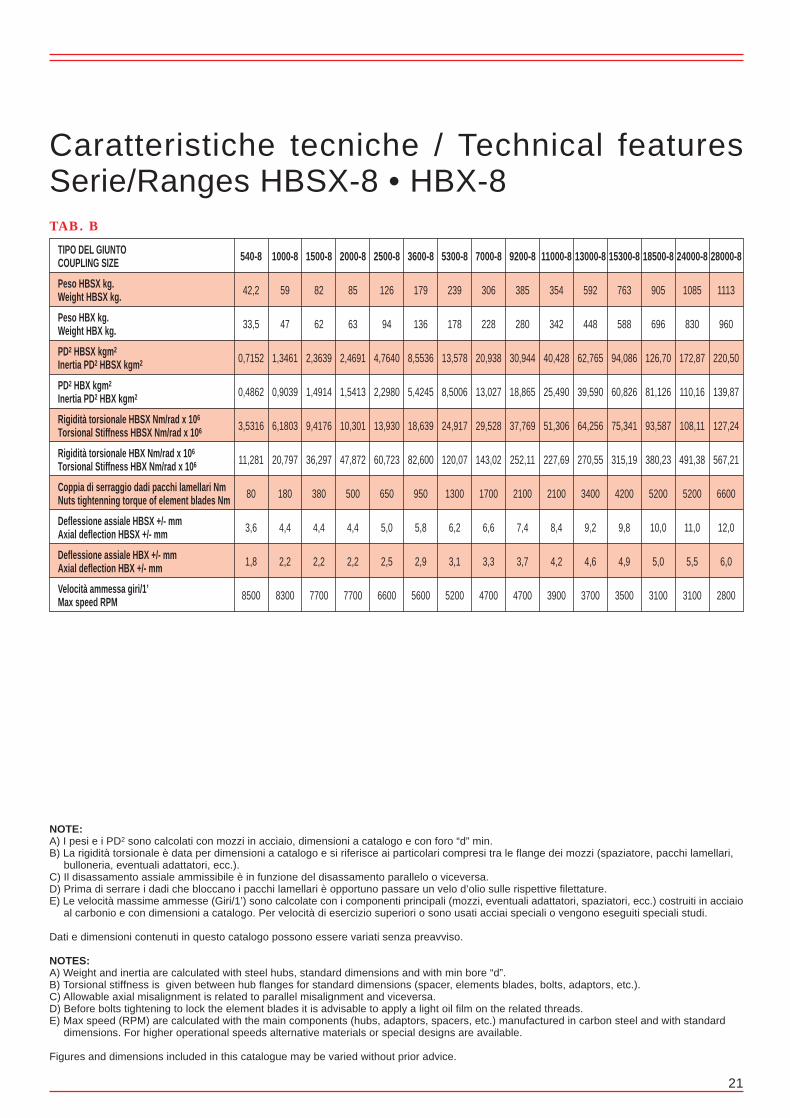
28 21
Serie/RangesHBSX-10
CON SPAZIATORE A 10 PERNIDa HP 1,9 a HP 36 a 1 GIRO/1’10 BOLTS WITH SPACERFrom HP 1,9 to HP 36 at 1 RPM
Disassamento angolare max = 0° 25’ per elementoMax angular misalignment = 0° 25’ each element
Disassamento parallelo max mm = 0.006 x (L3 + S)Max parallel misalignment = 0.006 x (L3 + S)
DIMENSIONI RIFERITE AI TIPI STANDARDPossono essere variate le dimensioni di lunghezza dei mozzi e dello spaziatore
DIMENSIONS REFERRED TO STANDARD VERSIONHubs and spacer length can be modified
1900-10
2500-10
3200-10
4600-10
6800-10
9000-10
11500-10
14000-10
16800-10
19700-10
23800-10
31000-10
36000-10
Potenza trasmis.a 1 giro/1’
Nominal ratingtransmissible at 1 RPM
TIPO
SIZE
Coppia tras.
Nominal Torque
Nm
13400
17600
22500
32300
47800
63200
80800
98400
118000
138400
167200
217800
253000
HP/n
1,90
2,50
3,20
4,60
6,80
9,00
11,50
14,00
16,80
19,70
23,80
31,00
36,00
KW/n
1,40
1,84
2,35
3,38
5,00
6,62
8,45
10,30
12,35
14,48
17,50
22,80
26,47
TAB. A
165
165
193
218
240
258
272
297
335
365
382
400
420
M
mm
118
115
134
151
180
199
211
210
224
230
245
273
285
L3
mm
153
153
172
190
223
255
270
272
286
292
310
343
357
L2
mm
17,5
19
19
19,5
21,5
28
29,5
31
31
31
32,5
35
36
S
mm
150
150
180
205
220
240
250
280
315
345
355
370
390
L1
mm
115
115
130
150
165
180
190
205
230
255
265
275
290
dmax
mm
453
453
532
600
663
735
770
832
916
982
1020
1083
1137
L
mm
275
275
308
346
375
410
445
470
510
555
587
630
655
D
mm
TIPO DEL GIUNTOCOUPLING SIZE
Peso HBSX kg.Weight HBSX kg.
Peso HBX kg.Weight HBX kg.
PD2 HBSX kgm2
Inertia PD2 HBSX kgm2
PD2 HBX kgm2
Inertia PD2 HBX kgm2
Rigidità torsionale HBSX Nm/rad x 106
Torsional Stiffness HBSX Nm/rad x 106
Rigidità torsionale HBX Nm/rad x 106
Torsional Stiffness HBX Nm/rad x 106
Coppia di serraggio dadi pacchi lamellari NmNuts tightenning torque of element blades Nm
Deflessione assiale HBSX +/- mmAxial deflection HBSX +/- mm
Deflessione assiale HBX +/- mmAxial deflection HBX +/- mm
Velocità ammessa giri/1’Max speed RPM
TAB. B
28000-8
1113
960
220,50
139,87
127,24
567,21
6600
12,0
6,0
2800
Caratteristiche tecniche / Technical featuresSerie/Ranges HBSX-8 • HBX-8
24000-8
1085
830
172,87
110,16
108,11
491,38
5200
11,0
5,5
3100
18500-8
905
696
126,70
81,126
93,587
380,23
5200
10,0
5,0
3100
15300-8
763
588
94,086
60,826
75,341
315,19
4200
9,8
4,9
3500
13000-8
592
448
62,765
39,590
64,256
270,55
3400
9,2
4,6
3700
11000-8
354
342
40,428
25,490
51,306
227,69
2100
8,4
4,2
3900
9200-8
385
280
30,944
18,865
37,769
252,11
2100
7,4
3,7
4700
7000-8
306
228
20,938
13,027
29,528
143,02
1700
6,6
3,3
4700
5300-8
239
178
13,578
8,5006
24,917
120,07
1300
6,2
3,1
5200
3600-8
179
136
8,5536
5,4245
18,639
82,600
950
5,8
2,9
5600
2500-8
126
94
4,7640
2,2980
13,930
60,723
650
5,0
2,5
6600
2000-8
85
63
2,4691
1,5413
10,301
47,872
500
4,4
2,2
7700
1500-8
82
62
2,3639
1,4914
9,4176
36,297
380
4,4
2,2
7700
1000-8
59
47
1,3461
0,9039
6,1803
20,797
180
4,4
2,2
8300
540-8
42,2
33,5
0,7152
0,4862
3,5316
11,281
80
3,6
1,8
8500
NOTE:A) I pesi e i PD2 sono calcolati con mozzi in acciaio, dimensioni a catalogo e con foro “d” min.B) La rigidità torsionale è data per dimensioni a catalogo e si riferisce ai particolari compresi tra le flange dei mozzi (spaziatore, pacchi lamellari, bulloneria, eventuali adattatori, ecc.).C) Il disassamento assiale ammissibile è in funzione del disassamento parallelo o viceversa.D) Prima di serrare i dadi che bloccano i pacchi lamellari è opportuno passare un velo d’olio sulle rispettive filettature.E) Le velocità massime ammesse (Giri/1’) sono calcolate con i componenti principali (mozzi, eventuali adattatori, spaziatori, ecc.) costruiti in acciaio al carbonio e con dimensioni a catalogo. Per velocità di esercizio superiori o sono usati acciai speciali o vengono eseguiti speciali studi.
Dati e dimensioni contenuti in questo catalogo possono essere variati senza preavviso.
NOTES:A) Weight and inertia are calculated with steel hubs, standard dimensions and with min bore “d”.B) Torsional stiffness is given between hub flanges for standard dimensions (spacer, elements blades, bolts, adaptors, etc.).C) Allowable axial misalignment is related to parallel misalignment and viceversa.D) Before bolts tightening to lock the element blades it is advisable to apply a light oil film on the related threads.E) Max speed (RPM) are calculated with the main components (hubs, adaptors, spacers, etc.) manufactured in carbon steel and with standard dimensions. For higher operational speeds alternative materials or special designs are available.
Figures and dimensions included in this catalogue may be varied without prior advice.
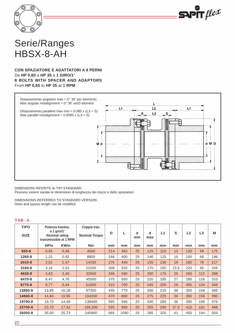
22 27
Serie/RangesHBSX-8-AH
CON SPAZIATORE E ADATTATORI A 8 PERNIDa HP 0,65 a HP 35 a 1 GIRO/1’8 BOLTS WITH SPACER AND ADAPTORSFrom HP 0,65 to HP 35 at 1 RPM
Disassamento angolare max = 0° 30’ per elementoMax angular misalignment = 0° 30’ each element
Disassamento parallelo max mm = 0.085 x (L3 + S)Max parallel misalignment = 0.0085 x (L3 + S)
DIMENSIONI RIFERITE AI TIPI STANDARDPossono essere variate le dimensioni di lunghezza dei mozzi e dello spaziatore
DIMENSIONS REFERRED TO STANDARD VERSIONHubs and spacer length can be modified
650-8
1260-8
2010-8
3160-8
4630-8
6470-8
8770-8
13850-8
14840-8
19700-8
23700-8
35000-8
Potenza trasmis.a 1 giro/1’
Nominal ratingtransmissible at 1 RPM
TIPO
SIZE
Coppia tras.
Nominal Torque
Nm
4500
8800
14100
22200
32500
45500
61600
97300
104200
138400
166,500
245900
HP/n
0,65
1,25
2,01
3,16
4,63
6,47
8,77
13,85
14,84
19,70
23,70
35,00
KW/n
0,48
0,92
1,47
2,32
3,40
4,76
6,44
10,18
10,90
14,48
17,42
25,73
TAB. A
175
196
217
245
288
310
346
365
390
476
498
556
M
mm
58
68
78
95
112
126
134
156
156
166
181
194
L3
mm
130
150
180
220
250
280
300
350
350
380
410
450
L2
mm
13
15
19
23,5
25
27
28
36
36
36
37,5
41
S
mm
110
125
130
150
170
185
200
210
225
280
290
320
L1
mm
125
140
155
175
200
220
245
260
275
340
355
395
dmax
mm
25
25
25
25
25
25
25
25
25
25
25
25
dmin
mm
350
400
440
520
590
650
700
770
800
940
990
1090
L
mm
TIPO DEL GIUNTOCOUPLING SIZE
Peso GCSX kg.Weight GCSX kg.
Peso GCX kg.Weight GCX kg.
PD2 GCSX kgm2
Inertia PD2 GCSX kgm2
PD2 GCX kgm2
Inertia PD2 GCX kgm2
Rigidità torsionale GCSX Nm/rad x 106
Torsional Stiffness GCSX Nm/rad x 106
Rigidità torsionale GCX Nm/rad x 106
Torsional Stiffness GCX Nm/rad x 106
Coppia di serraggio dadi pacchi lamellari NmNuts tightenning torque of element blades Nm
Deflessione assiale GCSX +/- mmAxial deflection GCSX +/- mm
Deflessione assiale GCX +/- mmAxial deflection GCX +/- mm
Velocità ammessa giri/1’Max speed RPM
TAB. B
35000-8
1307
1005
217,36
139,95
161,18
714,06
8000
12,0
6,0
1500
Caratteristiche tecniche / Technical featuresSerie/Ranges GCSX-8 • GCX-8
29700-8
1130
876
169,56
110,22
132,14
604,68
6600
11,0
5,5
1500
23700-8
960
748
128,798
84,257
118,21
489,61
5200
10,0
5,0
1500
19700-8
810
638
96,868
64,105
98,296
403,87
4200
9,8
4,9
1500
14800-8
625
484
63,488
41,330
73,477
301,16
3400
9,2
4,6
1500
12000-8
478
365
40,730
26,066
55,917
243,68
2700
8,4
4,2
2000
10400-8
400
295
30,853
19,021
43,556
212,09
2700
7,4
3,7
2000
8800-8
324
238
21,680
13,314
37,572
178,24
2100
6,6
3,3
2000
7100-8
255
186
14,304
8,7742
26,193
163,53
1700
6,2
3,1
2500
5250-8
197
145
9,3815
5,8071
24,427
124,09
1300
5,8
2,9
2500
3700-8
137
99
5,2112
3,1697
17,854
91,036
950
5,0
2,5
2500
2550-8
91
65
2,5951
1,5714
11,576
61,116
650
4,4
2,2
3000
1310-8
64,8
51,3
1,4397
0,9708
6,3765
27,173
270
4,4
2,2
3000
214
246
275
308
346
375
410
445
470
565
595
665
D
mm
870-8
42,5
33,5
0,7142
0,4801
4,5126
17,854
180
3,6
1,8
3000
NOTE:A) I pesi e i PD2 sono calcolati con mozzi in acciaio, dimensioni a catalogo e con foro “d” min.B) La rigidità torsionale è data per dimensioni a catalogo e si riferisce ai particolari compresi tra le flange dei mozzi (spaziatore, pacchi lamellari, bulloneria, eventuali adattatori, ecc.).C) Il disassamento assiale ammissibile è in funzione del disassamento parallelo o viceversa.D) Prima di serrare i dadi che bloccano i pacchi lamellari è opportuno passare un velo d’olio sulle rispettive filettature.E) Le velocità massime ammesse (Giri/1’) sono calcolate con i componenti principali (mozzi, eventuali adattatori, spaziatori, ecc.) costruiti in acciaio al carbonio e con dimensioni a catalogo. Per velocità di esercizio superiori o sono usati acciai speciali o vengono eseguiti speciali studi.
Dati e dimensioni contenuti in questo catalogo possono essere variati senza preavviso.
NOTES:A) Weight and inertia are calculated with steel hubs, standard dimensions and with min bore “d”.B) Torsional stiffness is given between hub flanges for standard dimensions (spacer, elements blades, bolts, adaptors, etc.).C) Allowable axial misalignment is related to parallel misalignment and viceversa.D) Before bolts tightening to lock the element blades it is advisable to apply a light oil film on the related threads.E) Max speed (RPM) are calculated with the main components (hubs, adaptors, spacers, etc.) manufactured in carbon steel and with standard dimensions. For higher operational speeds alternative materials or special designs are available.
Figures and dimensions included in this catalogue may be varied without prior advice.

26
Serie/RangesGCSX-8
CON SPAZIATORE A 8 PERNIDa HP 0,87 a HP 35 a 1 GIRO/1’8 BOLTS WITH SPACERFrom HP 0,87 to HP 35 at 1 RPM
870-8
1310-8
2550-8
3700-8
5250-8
7100-8
8800-8
10400-8
12000-8
14800-8
19700-8
23700-8
29700-8
35000-8
Potenza trasmis.a 1 giro/1’
Nominal ratingtransmissible at 1 RPM
TIPO
SIZE
Coppia tras.
Nominal Torque
Nm
6100
9200
17900
26000
36900
49900
61800
73000
84300
104000
138400
166500
208700
245900
HP/n
0,87
1,31
2,55
3,70
5,25
7,10
8,80
10,40
12,00
14,80
19,70
23,70
29,70
35,00
KW/n
0,64
0,96
1,87
2,72
3,86
5,22
6,47
7,65
8,82
10,88
14,48
17,42
21,83
25,73
TAB. A
145
168
177
203
230
252
272
292
318
351
384
404
425
445
M1
mm
137
159
163
188
213
230
250
270
295
328
360
378
398
413
M
mm
95
109
136
147
156
173
199
213
210
224
228
245
271
283
L3
mm
125
140
180
195
210
230
260
275
275
290
300
320
350
365
L2
mm
15
15,5
22
24
27
28,5
30,5
31
32,5
33
36
37,5
39,5
41
S
mm
115
130
135
155
180
195
210
225
245
270
300
315
330
345
L1
mm
100
115
125
142
160
175
190
205
220
245
265
280
295
310
d1max
mm
95
110
112
130
150
160
170
185
205
225
245
260
275
285
dmax
mm
25
25
25
25
258
25
25
25
25
25
25
25
25
25
d: d1min
mm
245
275,5
292
334
387
418,5
450,5
481
522,5
573
636
667,5
699,5
731
GCXL
mm
355
400
450
505
570
620
680
725
765
830
900
950
1010
1055
GCSXL
mm
211
240
269
308
346
375
410
440
466
510
555
587
618
650
D
mm
Disassamento angolare max = 0° 30’ per elementoMax angular misalignment = 0° 30’ each element
Disassamento parallelo max mm = 0,0085 x (L3 + S)Max parallel misalignment = 0,0085 x (L3 + S)
DIMENSIONI RIFERITE AI TIPI STANDARDPossono essere variate le dimensioni di lunghezza dei mozzie dello spaziatoreDIMENSIONS REFERRED TO STANDARD VERSIONHubs and spacer length can be modified
Serie/RangesGCX-8
SENZA SPAZIATORE A 8 PERNIDa HP 0,54 a HP 28 a 1 GIRO/1’8 BOLTS WITHOUT SPACERFrom HP 0,54 to HP 28 at 1 RPM
Disassamento angolare max = 0° 30’Max angular misalignment = 0° 30’
DIMENSIONI RIFERITE AI TIPI STANDARDPossono essere variate le dimensioni di lunghezza dei mozzi
DIMENSIONS REFERRED TO STANDARD VERSIONHubs and spacer length can be modified
23
TIPO DEL GIUNTOCOUPLING SIZE
Peso HBSX-8-AH kg.Weight HBSX-8-AH kg.
PD2 HBSX-8-AH kgm2
Inertia PD2 HBSX-8-AH kgm2
Rigidità torsionale HBSX-8-AH Nm/rad x 106
Torsional Stiffness HBSX-8-AH Nm/rad x 106
Coppia di serraggio bulloni mozzo NmNuts tightenning torque of hub Nm
Coppia di serraggio dadi pacchi lamellari NmNuts tightenning torque of element blades Nm
Deflessione assiale HBSX-8-AH +/- mmAxial deflection HBSX-8-AH +/- mm
Velocità ammessa giri/1’Max speed RPM
TAB. B
35000-8
1854
379,72
200,12
1400
8000
12,0
2800
Caratteristiche tecniche / Technical featuresSerie/Ranges HBSX-8-AH
23700-8
1323
216,74
138,32
950
5200
10,0
3100
19700-8
1147
169,02
118,70
750
4200
9,8
3500
14840-8
654
67,145
61,705
550
2100
8,4
3900
13850-8
564
52,036
50,423
550
2100
7,4
4200
8770-8
450
35,430
38,651
280
1700
6,6
4700
6470-8
341
22,258
30,607
280
1300
6,2
5200
4630-8
264
14,585
22,171
180
950
5,8
5600
3160-8
178
7,7045
16,088
280
650
5,0
6600
2010-8
118
3,9683
10,497
180
380
4,4
7700
1260-8
86,0
2,2824
6,6708
120
180
4,4
8300
650-8
59,0
1,2108
4,0221
70
80
3,6
8500
NOTE:A) I pesi e i PD2 sono calcolati con mozzi in acciaio, dimensioni a catalogo e con foro “d” min.B) La rigidità torsionale è data per dimensioni a catalogo e si riferisce ai particolari compresi tra le flange dei mozzi (spaziatore, pacchi lamellari, bulloneria, eventuali adattatori, ecc.).C) Il disassamento assiale ammissibile è in funzione del disassamento parallelo o viceversa.D) Prima di serrare i dadi che bloccano i pacchi lamellari è opportuno passare un velo d’olio sulle rispettive filettature.E) Le velocità massime ammesse (Giri/1’) sono calcolate con i componenti principali (mozzi, eventuali adattatori, spaziatori, ecc.) costruiti in acciaio al carbonio e con dimensioni a catalogo. Per velocità di esercizio superiori o sono usati acciai speciali o vengono eseguiti speciali studi.
Dati e dimensioni contenuti in questo catalogo possono essere variati senza preavviso.
NOTES:A) Weight and inertia are calculated with steel hubs, standard dimensions and with min bore “d”.B) Torsional stiffness is given between hub flanges for standard dimensions (spacer, elements blades, bolts, adaptors, etc.).C) Allowable axial misalignment is related to parallel misalignment and viceversa.D) Before bolts tightening to lock the element blades it is advisable to apply a light oil film on the related threads.E) Max speed (RPM) are calculated with the main components (hubs, adaptors, spacers, etc.) manufactured in carbon steel and with standard dimensions. For higher operational speeds alternative materials or special designs are available.
Figures and dimensions included in this catalogue may be varied without prior advice.

24 25
TIPO DEL GIUNTOCOUPLING SIZE
Peso HBSX-8-RH kg.Weight HBSX-8-RH kg.
PD2 HBSX-8-RH kgm2
Inertia PD2 HBSX-8-RH kgm2
Rigidità torsionale HBSX-8-RH Nm/rad x 106
Torsional Stiffness HBSX-8-RH Nm/rad x 106
Coppia di serraggio dadi spaziatori NmNuts tightenning torque of element blades Nm
Coppia di serraggio dadi pacchi lamellari NmNuts tightenning torque of element blades Nm
Deflessione assiale HBSX-8-RH +/- mmAxial deflection HBSX-8-RH +/- mm
Velocità ammessa giri/1’Max speed RPM
TAB. B
19700-8
625
97,363
174,81
500
4200
9,8
3500
Caratteristiche tecniche / Technical featuresSerie/Ranges HBSX-8-RH
14840-8
487
57,144
97,511
380
2100
8,4
3900
13850-8
352
36,567
81,227
380
2100
7,4
4200
8770-8
253
21,576
63,078
180
1700
6,6
4700
4630-8
165
10,235
35,610
180
950
5,8
5600
3160-8
115
5,6541
25,997
80
650
5,0
6600
2700-8
80,0
3,1936
20,111
80
500
4,4
7700
2010-8
68,0
2,7753
16,285
80
380
4,4
7700
1260-8
47,0
1,5263
9,5157
45
180
4,4
8300
650-8
29,5
0,7525
5,2974
45
80
3,6
8500
330-8
11,0
0,1383
2,5506
23
45
2,8
10000
170-8
8,0
0,0668
1,2753
23
23
2,0
14000
170-8
330-8
650-8
1260-8
2010-8
2700-8
3160-8
4630-8
8770-8
13850-8
14840-8
19700-8
Potenza trasmis.a 1 giro/1’
Nominal ratingtransmissible at 1 RPM
TIPO
SIZE
Coppia tras.
Nominal Torque
Nm
1200
2300
4500
8800
14100
19000
22200
32500
61600
97300
104200
138400
HP/n
0,17
0,33
0,65
1,25
2,01
2,70
3,16
4,63
8,77
13,85
14,34
19,70
KW/n
0,12
0,24
0,48
0,82
1,47
1,98
2,32
3,40
6,44
10,13
10,90
14,48
TAB. A
64
86
120
138
150
150
175
195
220
235
260
320
M
mm
16,3
18
25
28
34
35
41
46
57
63
63
73
L4
mm
40
48
51
71
79
100
117
136
138
160
190
232
L3
mm
3
3
3
5
5
6
6
8
8
8
8
10
L2
mm
8,2
9,5
13
15
19
23
23,5
25
28
36
36
36
S
mm
43
50
62
76
90
105
120
135
150
175
190
220
L1
mm
46
62
85
98
105
105
125
135
155
165
180
225
dmax
mm
25
25
25
25
25
25
25
25
25
25
25
25
dmin
mm
89
103
127
157
185
216
246
278
308
358
388
450
L
mm
119
148
214
246
275
275
308
346
410
445
470
555
D1
mm
155
185
260
295
330
330
365
415
475
535
560
675
D
mm
Serie/RangesHBSX-8-RH
CON MOZZI ROVESCIATI E SPAZIATORE IN DUE METÀ A 8 PERNIDa HP 0,17 a HP 19,7 a 1 GIRO/1’8 BOLTS WITH REVERSED HUBS AND SPACER IN TWO HALFSFrom HP 0,17 to HP 19,7 at 1 RPM
Disassamento angolare max = 0° 30’ per elementoMax angular misalignment = 0° 30’ each element
Disassamento parallelo max mm = 0.085 x (L3 + S)Max parallel misalignment = 0.0085 x (L3 + S)
DIMENSIONI RIFERITE AI TIPI STANDARDPossono essere variate le dimensioni di lunghezza dei mozzi e dello spaziatore
DIMENSIONS REFERRED TO STANDARD VERSIONHubs and spacer length can be modified
NOTE:A) I pesi e i PD2 sono calcolati con mozzi in acciaio, dimensioni a catalogo e con foro “d” min.B) La rigidità torsionale è data per dimensioni a catalogo e si riferisce ai particolari compresi tra le flange dei mozzi (spaziatore, pacchi lamellari, bulloneria, eventuali adattatori, ecc.).C) Il disassamento assiale ammissibile è in funzione del disassamento parallelo o viceversa.D) Prima di serrare i dadi che bloccano i pacchi lamellari è opportuno passare un velo d’olio sulle rispettive filettature.E) Le velocità massime ammesse (Giri/1’) sono calcolate con i componenti principali (mozzi, eventuali adattatori, spaziatori, ecc.) costruiti in acciaio al carbonio e con dimensioni a catalogo. Per velocità di esercizio superiori o sono usati acciai speciali o vengono eseguiti speciali studi.
Dati e dimensioni contenuti in questo catalogo possono essere variati senza preavviso.
NOTES:A) Weight and inertia are calculated with steel hubs, standard dimensions and with min bore “d”.B) Torsional stiffness is given between hub flanges for standard dimensions (spacer, elements blades, bolts, adaptors, etc.).C) Allowable axial misalignment is related to parallel misalignment and viceversa.D) Before bolts tightening to lock the element blades it is advisable to apply a light oil film on the related threads.E) Max speed (RPM) are calculated with the main components (hubs, adaptors, spacers, etc.) manufactured in carbon steel and with standard dimensions. For higher operational speeds alternative materials or special designs are available.
Figures and dimensions included in this catalogue may be varied without prior advice.

26
Serie/RangesGCSX-8
CON SPAZIATORE A 8 PERNIDa HP 0,87 a HP 35 a 1 GIRO/1’8 BOLTS WITH SPACERFrom HP 0,87 to HP 35 at 1 RPM
870-8
1310-8
2550-8
3700-8
5250-8
7100-8
8800-8
10400-8
12000-8
14800-8
19700-8
23700-8
29700-8
35000-8
Potenza trasmis.a 1 giro/1’
Nominal ratingtransmissible at 1 RPM
TIPO
SIZE
Coppia tras.
Nominal Torque
Nm
6100
9200
17900
26000
36900
49900
61800
73000
84300
104000
138400
166500
208700
245900
HP/n
0,87
1,31
2,55
3,70
5,25
7,10
8,80
10,40
12,00
14,80
19,70
23,70
29,70
35,00
KW/n
0,64
0,96
1,87
2,72
3,86
5,22
6,47
7,65
8,82
10,88
14,48
17,42
21,83
25,73
TAB. A
145
168
177
203
230
252
272
292
318
351
384
404
425
445
M1
mm
137
159
163
188
213
230
250
270
295
328
360
378
398
413
M
mm
95
109
136
147
156
173
199
213
210
224
228
245
271
283
L3
mm
125
140
180
195
210
230
260
275
275
290
300
320
350
365
L2
mm
15
15,5
22
24
27
28,5
30,5
31
32,5
33
36
37,5
39,5
41
S
mm
115
130
135
155
180
195
210
225
245
270
300
315
330
345
L1
mm
100
115
125
142
160
175
190
205
220
245
265
280
295
310
d1max
mm
95
110
112
130
150
160
170
185
205
225
245
260
275
285
dmax
mm
25
25
25
25
258
25
25
25
25
25
25
25
25
25
d: d1min
mm
245
275,5
292
334
387
418,5
450,5
481
522,5
573
636
667,5
699,5
731
GCXL
mm
355
400
450
505
570
620
680
725
765
830
900
950
1010
1055
GCSXL
mm
211
240
269
308
346
375
410
440
466
510
555
587
618
650
D
mm
Disassamento angolare max = 0° 30’ per elementoMax angular misalignment = 0° 30’ each element
Disassamento parallelo max mm = 0,0085 x (L3 + S)Max parallel misalignment = 0,0085 x (L3 + S)
DIMENSIONI RIFERITE AI TIPI STANDARDPossono essere variate le dimensioni di lunghezza dei mozzie dello spaziatoreDIMENSIONS REFERRED TO STANDARD VERSIONHubs and spacer length can be modified
Serie/RangesGCX-8
SENZA SPAZIATORE A 8 PERNIDa HP 0,54 a HP 28 a 1 GIRO/1’8 BOLTS WITHOUT SPACERFrom HP 0,54 to HP 28 at 1 RPM
Disassamento angolare max = 0° 30’Max angular misalignment = 0° 30’
DIMENSIONI RIFERITE AI TIPI STANDARDPossono essere variate le dimensioni di lunghezza dei mozzi
DIMENSIONS REFERRED TO STANDARD VERSIONHubs and spacer length can be modified
23
TIPO DEL GIUNTOCOUPLING SIZE
Peso HBSX-8-AH kg.Weight HBSX-8-AH kg.
PD2 HBSX-8-AH kgm2
Inertia PD2 HBSX-8-AH kgm2
Rigidità torsionale HBSX-8-AH Nm/rad x 106
Torsional Stiffness HBSX-8-AH Nm/rad x 106
Coppia di serraggio bulloni mozzo NmNuts tightenning torque of hub Nm
Coppia di serraggio dadi pacchi lamellari NmNuts tightenning torque of element blades Nm
Deflessione assiale HBSX-8-AH +/- mmAxial deflection HBSX-8-AH +/- mm
Velocità ammessa giri/1’Max speed RPM
TAB. B
35000-8
1854
379,72
200,12
1400
8000
12,0
2800
Caratteristiche tecniche / Technical featuresSerie/Ranges HBSX-8-AH
23700-8
1323
216,74
138,32
950
5200
10,0
3100
19700-8
1147
169,02
118,70
750
4200
9,8
3500
14840-8
654
67,145
61,705
550
2100
8,4
3900
13850-8
564
52,036
50,423
550
2100
7,4
4200
8770-8
450
35,430
38,651
280
1700
6,6
4700
6470-8
341
22,258
30,607
280
1300
6,2
5200
4630-8
264
14,585
22,171
180
950
5,8
5600
3160-8
178
7,7045
16,088
280
650
5,0
6600
2010-8
118
3,9683
10,497
180
380
4,4
7700
1260-8
86,0
2,2824
6,6708
120
180
4,4
8300
650-8
59,0
1,2108
4,0221
70
80
3,6
8500
NOTE:A) I pesi e i PD2 sono calcolati con mozzi in acciaio, dimensioni a catalogo e con foro “d” min.B) La rigidità torsionale è data per dimensioni a catalogo e si riferisce ai particolari compresi tra le flange dei mozzi (spaziatore, pacchi lamellari, bulloneria, eventuali adattatori, ecc.).C) Il disassamento assiale ammissibile è in funzione del disassamento parallelo o viceversa.D) Prima di serrare i dadi che bloccano i pacchi lamellari è opportuno passare un velo d’olio sulle rispettive filettature.E) Le velocità massime ammesse (Giri/1’) sono calcolate con i componenti principali (mozzi, eventuali adattatori, spaziatori, ecc.) costruiti in acciaio al carbonio e con dimensioni a catalogo. Per velocità di esercizio superiori o sono usati acciai speciali o vengono eseguiti speciali studi.
Dati e dimensioni contenuti in questo catalogo possono essere variati senza preavviso.
NOTES:A) Weight and inertia are calculated with steel hubs, standard dimensions and with min bore “d”.B) Torsional stiffness is given between hub flanges for standard dimensions (spacer, elements blades, bolts, adaptors, etc.).C) Allowable axial misalignment is related to parallel misalignment and viceversa.D) Before bolts tightening to lock the element blades it is advisable to apply a light oil film on the related threads.E) Max speed (RPM) are calculated with the main components (hubs, adaptors, spacers, etc.) manufactured in carbon steel and with standard dimensions. For higher operational speeds alternative materials or special designs are available.
Figures and dimensions included in this catalogue may be varied without prior advice.

22 27
Serie/RangesHBSX-8-AH
CON SPAZIATORE E ADATTATORI A 8 PERNIDa HP 0,65 a HP 35 a 1 GIRO/1’8 BOLTS WITH SPACER AND ADAPTORSFrom HP 0,65 to HP 35 at 1 RPM
Disassamento angolare max = 0° 30’ per elementoMax angular misalignment = 0° 30’ each element
Disassamento parallelo max mm = 0.085 x (L3 + S)Max parallel misalignment = 0.0085 x (L3 + S)
DIMENSIONI RIFERITE AI TIPI STANDARDPossono essere variate le dimensioni di lunghezza dei mozzi e dello spaziatore
DIMENSIONS REFERRED TO STANDARD VERSIONHubs and spacer length can be modified
650-8
1260-8
2010-8
3160-8
4630-8
6470-8
8770-8
13850-8
14840-8
19700-8
23700-8
35000-8
Potenza trasmis.a 1 giro/1’
Nominal ratingtransmissible at 1 RPM
TIPO
SIZE
Coppia tras.
Nominal Torque
Nm
4500
8800
14100
22200
32500
45500
61600
97300
104200
138400
166,500
245900
HP/n
0,65
1,25
2,01
3,16
4,63
6,47
8,77
13,85
14,84
19,70
23,70
35,00
KW/n
0,48
0,92
1,47
2,32
3,40
4,76
6,44
10,18
10,90
14,48
17,42
25,73
TAB. A
175
196
217
245
288
310
346
365
390
476
498
556
M
mm
58
68
78
95
112
126
134
156
156
166
181
194
L3
mm
130
150
180
220
250
280
300
350
350
380
410
450
L2
mm
13
15
19
23,5
25
27
28
36
36
36
37,5
41
S
mm
110
125
130
150
170
185
200
210
225
280
290
320
L1
mm
125
140
155
175
200
220
245
260
275
340
355
395
dmax
mm
25
25
25
25
25
25
25
25
25
25
25
25
dmin
mm
350
400
440
520
590
650
700
770
800
940
990
1090
L
mm
TIPO DEL GIUNTOCOUPLING SIZE
Peso GCSX kg.Weight GCSX kg.
Peso GCX kg.Weight GCX kg.
PD2 GCSX kgm2
Inertia PD2 GCSX kgm2
PD2 GCX kgm2
Inertia PD2 GCX kgm2
Rigidità torsionale GCSX Nm/rad x 106
Torsional Stiffness GCSX Nm/rad x 106
Rigidità torsionale GCX Nm/rad x 106
Torsional Stiffness GCX Nm/rad x 106
Coppia di serraggio dadi pacchi lamellari NmNuts tightenning torque of element blades Nm
Deflessione assiale GCSX +/- mmAxial deflection GCSX +/- mm
Deflessione assiale GCX +/- mmAxial deflection GCX +/- mm
Velocità ammessa giri/1’Max speed RPM
TAB. B
35000-8
1307
1005
217,36
139,95
161,18
714,06
8000
12,0
6,0
1500
Caratteristiche tecniche / Technical featuresSerie/Ranges GCSX-8 • GCX-8
29700-8
1130
876
169,56
110,22
132,14
604,68
6600
11,0
5,5
1500
23700-8
960
748
128,798
84,257
118,21
489,61
5200
10,0
5,0
1500
19700-8
810
638
96,868
64,105
98,296
403,87
4200
9,8
4,9
1500
14800-8
625
484
63,488
41,330
73,477
301,16
3400
9,2
4,6
1500
12000-8
478
365
40,730
26,066
55,917
243,68
2700
8,4
4,2
2000
10400-8
400
295
30,853
19,021
43,556
212,09
2700
7,4
3,7
2000
8800-8
324
238
21,680
13,314
37,572
178,24
2100
6,6
3,3
2000
7100-8
255
186
14,304
8,7742
26,193
163,53
1700
6,2
3,1
2500
5250-8
197
145
9,3815
5,8071
24,427
124,09
1300
5,8
2,9
2500
3700-8
137
99
5,2112
3,1697
17,854
91,036
950
5,0
2,5
2500
2550-8
91
65
2,5951
1,5714
11,576
61,116
650
4,4
2,2
3000
1310-8
64,8
51,3
1,4397
0,9708
6,3765
27,173
270
4,4
2,2
3000
214
246
275
308
346
375
410
445
470
565
595
665
D
mm
870-8
42,5
33,5
0,7142
0,4801
4,5126
17,854
180
3,6
1,8
3000
NOTE:A) I pesi e i PD2 sono calcolati con mozzi in acciaio, dimensioni a catalogo e con foro “d” min.B) La rigidità torsionale è data per dimensioni a catalogo e si riferisce ai particolari compresi tra le flange dei mozzi (spaziatore, pacchi lamellari, bulloneria, eventuali adattatori, ecc.).C) Il disassamento assiale ammissibile è in funzione del disassamento parallelo o viceversa.D) Prima di serrare i dadi che bloccano i pacchi lamellari è opportuno passare un velo d’olio sulle rispettive filettature.E) Le velocità massime ammesse (Giri/1’) sono calcolate con i componenti principali (mozzi, eventuali adattatori, spaziatori, ecc.) costruiti in acciaio al carbonio e con dimensioni a catalogo. Per velocità di esercizio superiori o sono usati acciai speciali o vengono eseguiti speciali studi.
Dati e dimensioni contenuti in questo catalogo possono essere variati senza preavviso.
NOTES:A) Weight and inertia are calculated with steel hubs, standard dimensions and with min bore “d”.B) Torsional stiffness is given between hub flanges for standard dimensions (spacer, elements blades, bolts, adaptors, etc.).C) Allowable axial misalignment is related to parallel misalignment and viceversa.D) Before bolts tightening to lock the element blades it is advisable to apply a light oil film on the related threads.E) Max speed (RPM) are calculated with the main components (hubs, adaptors, spacers, etc.) manufactured in carbon steel and with standard dimensions. For higher operational speeds alternative materials or special designs are available.
Figures and dimensions included in this catalogue may be varied without prior advice.

28 21
Serie/RangesHBSX-10
CON SPAZIATORE A 10 PERNIDa HP 1,9 a HP 36 a 1 GIRO/1’10 BOLTS WITH SPACERFrom HP 1,9 to HP 36 at 1 RPM
Disassamento angolare max = 0° 25’ per elementoMax angular misalignment = 0° 25’ each element
Disassamento parallelo max mm = 0.006 x (L3 + S)Max parallel misalignment = 0.006 x (L3 + S)
DIMENSIONI RIFERITE AI TIPI STANDARDPossono essere variate le dimensioni di lunghezza dei mozzi e dello spaziatore
DIMENSIONS REFERRED TO STANDARD VERSIONHubs and spacer length can be modified
1900-10
2500-10
3200-10
4600-10
6800-10
9000-10
11500-10
14000-10
16800-10
19700-10
23800-10
31000-10
36000-10
Potenza trasmis.a 1 giro/1’
Nominal ratingtransmissible at 1 RPM
TIPO
SIZE
Coppia tras.
Nominal Torque
Nm
13400
17600
22500
32300
47800
63200
80800
98400
118000
138400
167200
217800
253000
HP/n
1,90
2,50
3,20
4,60
6,80
9,00
11,50
14,00
16,80
19,70
23,80
31,00
36,00
KW/n
1,40
1,84
2,35
3,38
5,00
6,62
8,45
10,30
12,35
14,48
17,50
22,80
26,47
TAB. A
165
165
193
218
240
258
272
297
335
365
382
400
420
M
mm
118
115
134
151
180
199
211
210
224
230
245
273
285
L3
mm
153
153
172
190
223
255
270
272
286
292
310
343
357
L2
mm
17,5
19
19
19,5
21,5
28
29,5
31
31
31
32,5
35
36
S
mm
150
150
180
205
220
240
250
280
315
345
355
370
390
L1
mm
115
115
130
150
165
180
190
205
230
255
265
275
290
dmax
mm
453
453
532
600
663
735
770
832
916
982
1020
1083
1137
L
mm
275
275
308
346
375
410
445
470
510
555
587
630
655
D
mm
TIPO DEL GIUNTOCOUPLING SIZE
Peso HBSX kg.Weight HBSX kg.
Peso HBX kg.Weight HBX kg.
PD2 HBSX kgm2
Inertia PD2 HBSX kgm2
PD2 HBX kgm2
Inertia PD2 HBX kgm2
Rigidità torsionale HBSX Nm/rad x 106
Torsional Stiffness HBSX Nm/rad x 106
Rigidità torsionale HBX Nm/rad x 106
Torsional Stiffness HBX Nm/rad x 106
Coppia di serraggio dadi pacchi lamellari NmNuts tightenning torque of element blades Nm
Deflessione assiale HBSX +/- mmAxial deflection HBSX +/- mm
Deflessione assiale HBX +/- mmAxial deflection HBX +/- mm
Velocità ammessa giri/1’Max speed RPM
TAB. B
28000-8
1113
960
220,50
139,87
127,24
567,21
6600
12,0
6,0
2800
Caratteristiche tecniche / Technical featuresSerie/Ranges HBSX-8 • HBX-8
24000-8
1085
830
172,87
110,16
108,11
491,38
5200
11,0
5,5
3100
18500-8
905
696
126,70
81,126
93,587
380,23
5200
10,0
5,0
3100
15300-8
763
588
94,086
60,826
75,341
315,19
4200
9,8
4,9
3500
13000-8
592
448
62,765
39,590
64,256
270,55
3400
9,2
4,6
3700
11000-8
354
342
40,428
25,490
51,306
227,69
2100
8,4
4,2
3900
9200-8
385
280
30,944
18,865
37,769
252,11
2100
7,4
3,7
4700
7000-8
306
228
20,938
13,027
29,528
143,02
1700
6,6
3,3
4700
5300-8
239
178
13,578
8,5006
24,917
120,07
1300
6,2
3,1
5200
3600-8
179
136
8,5536
5,4245
18,639
82,600
950
5,8
2,9
5600
2500-8
126
94
4,7640
2,2980
13,930
60,723
650
5,0
2,5
6600
2000-8
85
63
2,4691
1,5413
10,301
47,872
500
4,4
2,2
7700
1500-8
82
62
2,3639
1,4914
9,4176
36,297
380
4,4
2,2
7700
1000-8
59
47
1,3461
0,9039
6,1803
20,797
180
4,4
2,2
8300
540-8
42,2
33,5
0,7152
0,4862
3,5316
11,281
80
3,6
1,8
8500
NOTE:A) I pesi e i PD2 sono calcolati con mozzi in acciaio, dimensioni a catalogo e con foro “d” min.B) La rigidità torsionale è data per dimensioni a catalogo e si riferisce ai particolari compresi tra le flange dei mozzi (spaziatore, pacchi lamellari, bulloneria, eventuali adattatori, ecc.).C) Il disassamento assiale ammissibile è in funzione del disassamento parallelo o viceversa.D) Prima di serrare i dadi che bloccano i pacchi lamellari è opportuno passare un velo d’olio sulle rispettive filettature.E) Le velocità massime ammesse (Giri/1’) sono calcolate con i componenti principali (mozzi, eventuali adattatori, spaziatori, ecc.) costruiti in acciaio al carbonio e con dimensioni a catalogo. Per velocità di esercizio superiori o sono usati acciai speciali o vengono eseguiti speciali studi.
Dati e dimensioni contenuti in questo catalogo possono essere variati senza preavviso.
NOTES:A) Weight and inertia are calculated with steel hubs, standard dimensions and with min bore “d”.B) Torsional stiffness is given between hub flanges for standard dimensions (spacer, elements blades, bolts, adaptors, etc.).C) Allowable axial misalignment is related to parallel misalignment and viceversa.D) Before bolts tightening to lock the element blades it is advisable to apply a light oil film on the related threads.E) Max speed (RPM) are calculated with the main components (hubs, adaptors, spacers, etc.) manufactured in carbon steel and with standard dimensions. For higher operational speeds alternative materials or special designs are available.
Figures and dimensions included in this catalogue may be varied without prior advice.
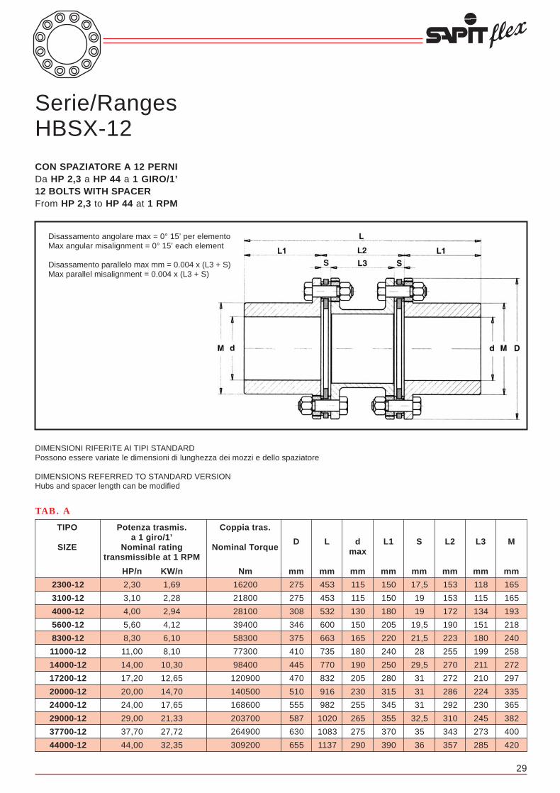
20
Serie/RangesHBSX-8
CON SPAZIATORE A 8 PERNIDa HP 0,54 a HP 28 a 1 GIRO/1’8 BOLTS WITH SPACERFrom HP 0,54 to HP 28 at 1 RPM
540-8
1000-8
1500-8
2000-8
2500-8
3600-8
5300-8
7000-8
9200-8
11000-8
13000-8
15300-8
18500-8
24000-8
28000-8
Potenza trasmis.a 1 giro/1’
Nominal ratingtransmissible at 1 RPM
TIPO
SIZE
Coppia tras.
Nominal Torque
Nm
3800
7000
10500
14000
17500
25300
37300
49200
64600
77300
91300
107500
130000
168600
196700
HP/n
0,54
1,00
1,50
2,00
2,50
3,60
5,30
7,00
9,20
11,00
13,00
15,30
18,50
24,00
28,00
KW/n
0,40
0,74
1,10
1,47
1,84
2,65
3,90
5,15
6,77
8,10
9,56
11,25
13,60
17,65
20,60
TAB. A
150
170
182
182
208
235
255
276
296
322
350
383
402
428
448
M1
mm
138
155
170
170
193
218
238
258
272
297
320
360
378
400
420
M
mm
91
103
120
127
147
157
177
199
211
208
223
233
245
275
288
L3
mm
115
130
155
165
185
200
225
255
270
270
285
295
310
345
360
L2
mm
12
13,5
17,5
19
19
21,5
24
28
29,5
31
31
31
32,5
35
36
S
mm
110
120
125
125
145
165
180
195
205
220
245
270
285
300
315
L1
mm
105
115
125
125
145
165
180
195
205
220
245
270
285
300
315
d1max
mm
95
110
120
120
135
150
165
180
190
205
225
255
265
275
290
dmax
mm
25
25
25
25
258
25
25
25
25
25
25
25
25
25
25
d: d1min
mm
232
253,5
267,5
269
309
351,5
384
418
439,5
471
521
571
602,5
635
666
HBXL
mm
335
370
405
415
475
530
585
645
680
710
775
835
880
945
990
HBSXL
mm
214
246
275
275
308
346
375
410
445
470
510
555
587
630
655
D
mm
Disassamento angolare max = 0° 30’ per elementoMax angular misalignment = 0° 30’ each element
Disassamento parallelo max mm = 0,0085 x (L3 + S)Max parallel misalignment = 0,0085 x (L3 + S)
DIMENSIONI RIFERITE AI TIPI STANDARDPossono essere variate le dimensioni di lunghezza dei mozzie dello spaziatoreDIMENSIONS REFERRED TO STANDARD VERSIONHubs and spacer length can be modified
Serie/RangesHBX-8
SENZA SPAZIATORE A 8 PERNIDa HP 0,54 a HP 28 a 1 GIRO/1’8 BOLTS WITHOUT SPACERFrom HP 0,54 to HP 28 at 1 RPM
Disassamento angolare max = 0° 30’Max angular misalignment = 0° 30’
DIMENSIONI RIFERITE AI TIPI STANDARDPossono essere variate le dimensioni di lunghezza dei mozzi
DIMENSIONS REFERRED TO STANDARD VERSIONHubs and spacer length can be modified
29
Serie/RangesHBSX-12
CON SPAZIATORE A 12 PERNIDa HP 2,3 a HP 44 a 1 GIRO/1’12 BOLTS WITH SPACERFrom HP 2,3 to HP 44 at 1 RPM
Disassamento angolare max = 0° 15’ per elementoMax angular misalignment = 0° 15’ each element
Disassamento parallelo max mm = 0.004 x (L3 + S)Max parallel misalignment = 0.004 x (L3 + S)
DIMENSIONI RIFERITE AI TIPI STANDARDPossono essere variate le dimensioni di lunghezza dei mozzi e dello spaziatore
DIMENSIONS REFERRED TO STANDARD VERSIONHubs and spacer length can be modified
2300-12
3100-12
4000-12
5600-12
8300-12
11000-12
14000-12
17200-12
20000-12
24000-12
29000-12
37700-12
44000-12
Potenza trasmis.a 1 giro/1’
Nominal ratingtransmissible at 1 RPM
TIPO
SIZE
Coppia tras.
Nominal Torque
Nm
16200
21800
28100
39400
58300
77300
98400
120900
140500
168600
203700
264900
309200
HP/n
2,30
3,10
4,00
5,60
8,30
11,00
14,00
17,20
20,00
24,00
29,00
37,70
44,00
KW/n
1,69
2,28
2,94
4,12
6,10
8,10
10,30
12,65
14,70
17,65
21,33
27,72
32,35
TAB. A
165
165
193
218
240
258
272
297
335
365
382
400
420
M
mm
118
115
134
151
180
199
211
210
224
230
245
273
285
L3
mm
153
153
172
190
223
255
270
272
286
292
310
343
357
L2
mm
17,5
19
19
19,5
21,5
28
29,5
31
31
31
32,5
35
36
S
mm
150
150
180
205
220
240
250
280
315
345
355
370
390
L1
mm
115
115
130
150
165
180
190
205
230
255
265
275
290
dmax
mm
453
453
532
600
663
735
770
832
916
982
1020
1083
1137
L
mm
275
275
308
346
375
410
445
470
510
555
587
630
655
D
mm

30 19
Serie/RangesBE-10
CON SPAZIATORE PER GRANDI POTENZE A 10 PERNIDa HP 45 a HP 137 a 1 GIRO/1’10 BOLTS WITH SPACER FOR HIGH POWERSFrom HP 45 to HP 137 at 1 RPM
Disassamento angolare max = 0° 25’ per elementoMax angular misalignment = 0° 25’ each element
Disassamento parallelo max mm = 0.006 x (L3 + S)Max parallel misalignment = 0.006 x (L3 + S)
DIMENSIONI RIFERITE AI TIPI STANDARDPossono essere variate le dimensioni di lunghezza dei mozzi e dello spaziatore
DIMENSIONS REFERRED TO STANDARD VERSIONHubs and spacer length can be modified
45500-10
49500-10
60000-10
67500-10
75000-10
89000-10
98000-10
108000-10
122000-10
137000-10
Potenza trasmis.a 1 giro/1’
Nominal ratingtransmissible at 1 RPM
TIPO
SIZE
Coppia tras.
Nominal Torque
Nm
319700
347800
421500
474300
527000
625300
688500
758800
857200
962600
HP/n
45,50
49,50
60,00
67,50
75,00
89,00
98,00
108,00
122,00
137,00
KW/n
33,45
36,40
44,10
49,60
55,10
65,40
72,00
79,40
89,70
100,70
TAB. A
435
460
480
500
525
540
560
580
600
625
M
mm
235
240
256
264
272
281
289
297
308
339
L3
mm
315
320
340
350
360
375
385
395
410
445
L2
mm
40
40
42
43
44
47
48
49
51
53
S
mm
405
425
445
465
485
500
520
540
560
580
L1
mm
300
315
330
345
360
370
385
400
415
430
dmax
mm
1125
1170
1230
1280
1330
1375
1425
1475
1530
1605
L
mm
695
725
755
785
815
845
875
905
935
965
D
mm
TIPO DEL GIUNTOCOUPLING SIZE
Peso HPSX kg.Weight HPSX kg.
Peso HPX kg.Weight HPX kg.
PD2 HPSX kgm2
Inertia PD2 HPSX kgm2
PD2 HPX kgm2
Inertia PD2 HPX kgm2
Rigidità torsionale HPSX Nm/rad x 106
Torsional Stiffness HPSX Nm/rad x 106
Rigidità torsionale HPX Nm/rad x 106
Torsional Stiffness GHPX Nm/rad x 106
Coppia di serraggio dadi pacchi lamellari NmNuts tightenning torque of element blades Nm
Deflessione assiale HPSX +/- mmAxial deflection HPSX +/- mm
Deflessione assiale HPX +/- mmAxial deflection HPX +/- mm
Velocità ammessa giri/1’Max speed RPM
TAB. B
1300-6
50,0
41,0
1,3589
0,7959
4,9442
19,423
500
5,4
2,7
8250
Caratteristiche tecniche / Technical featuresSerie/Ranges HPSX-6 • HPX-6
860-6
40,0
26,0
0,6567
0,3846
3,0803
12,753
270
4,6
2,3
9600
470-6
22,8
15,8
0,2969
0,1715
1,5794
6,9062
180
4,2
2,1
11600
240-6
15,5
11,5
0,1525
0,0935
0,9221
3,5316
80
3,8
1,9
12800
130-6
9,5
7,0
0,0686
0,0416
0,6769
2,0307
45
3,4
1,7
14000
80-6
6,2
4,6
0,0302
0,0181
0,4415
1,2753
23
3
1,5
18750
NOTE:A) I pesi e i PD2 sono calcolati con mozzi in acciaio, dimensioni a catalogo e con foro “d” min.B) La rigidità torsionale è data per dimensioni a catalogo e si riferisce ai particolari compresi tra le flange dei mozzi (spaziatore, pacchi lamellari, bulloneria, eventuali adattatori, ecc.).C) Il disassamento assiale ammissibile è in funzione del disassamento parallelo o viceversa.D) Prima di serrare i dadi che bloccano i pacchi lamellari è opportuno passare un velo d’olio sulle rispettive filettature.E) Le velocità massime ammesse (Giri/1’) sono calcolate con i componenti principali (mozzi, eventuali adattatori, spaziatori, ecc.) costruiti in acciaio al carbonio e con dimensioni a catalogo. Per velocità di esercizio superiori o sono usati acciai speciali o vengono eseguiti speciali studi.
Dati e dimensioni contenuti in questo catalogo possono essere variati senza preavviso.
NOTES:A) Weight and inertia are calculated with steel hubs, standard dimensions and with min bore “d”.B) Torsional stiffness is given between hub flanges for standard dimensions (spacer, elements blades, bolts, adaptors, etc.).C) Allowable axial misalignment is related to parallel misalignment and viceversa.D) Before bolts tightening to lock the element blades it is advisable to apply a light oil film on the related threads.E) Max speed (RPM) are calculated with the main components (hubs, adaptors, spacers, etc.) manufactured in carbon steel and with standard dimensions. For higher operational speeds alternative materials or special designs are available.
Figures and dimensions included in this catalogue may be varied without prior advice.

18
Serie/RangesHPSX-6
CON SPAZIATORE A 6 PERNIDa HP 40,08 a HP 1,3 a 1 GIRO/1’6 BOLTS WITH SPACERFrom HP 40,08 to HP 1,3 at 1 RPM
80-6
130-6
240-6
470-6
860-6
130-6
Potenza trasmis.a 1 giro/1’
Nominal ratingtransmissible at 1 RPM
TIPO
SIZE
Coppia tras.
Nominal Torque
Nm
560
900
1700
3300
6000
9100
HP/n
0,080
0,128
0,242
0,470
0,854
1,295
KW/n
0,059
0,094
0,178
0,345
0,628
0,952
TAB. A
74
81
97
104
124
143
M
mm
44
53
67
83
89
97
L3
mm
65
75
90
110
120
130
L2
mm
10,5
11,0
11,5
13,5
15,5
16,5
S
mm
55
65
75
80
95
110
L1
mm
52
56
68
72
85
100
dmax
mm
17
17
17
20
20
20
dmin
mm
120,5
141
161,5
173,5
205,5
236,5
HPXL
mm
175
205
240
270
310
350
HPSXL
mm
119
137
161
180
212
244
D
mm
Disassamento angolare max = 0° 45’ per elementoMax angular misalignment = 0° 45’ each element
Disassamento parallelo max mm = 0.012 x (L3 + S)Max parallel misalignment = 0.012 x (L3 + S)
DIMENSIONI RIFERITE AI TIPI STANDARDPossono essere variate le dimensioni di lunghezza dei mozzie dello spaziatore
DIMENSIONS REFERRED TO STANDARD VERSIONHubs and spacer length can be modified
Serie/RangesHPX-6
SENZA SPAZIATORE A 6 PERNIDa HP 40,08 a HP 1,3 a 1 GIRO/1’6 BOLTS WITHOUT SPACERFrom HP 40,08 to HP 1,3 at 1 RPM
Disassamento angolare max = 0° 45’Max angular misalignment = 0° 45’
DIMENSIONI RIFERITE AI TIPI STANDARDPossono essere variate le dimensioni di lunghezza dei mozzi
DIMENSIONS REFERRED TO STANDARD VERSIONHubs and spacer length can be modified
31
Serie/RangesBE-12
CON SPAZIATORE PER GRANDI POTENZE A 12 PERNIDa HP 55 a HP 148 a 1 GIRO/1’12 BOLTS WITH SPACER FOR HIGH POWERSFrom HP 55 to HP 148 at 1 RPM
Disassamento angolare max = 0° 15’ per elementoMax angular misalignment = 0° 15’ each element
Disassamento parallelo max mm = 0.004 x (L3 + S)Max parallel misalignment = 0.004 x (L3 + S)
DIMENSIONI RIFERITE AI TIPI STANDARDPossono essere variate le dimensioni di lunghezza dei mozzi e dello spaziatore
DIMENSIONS REFERRED TO STANDARD VERSIONHubs and spacer length can be modified
55500-12
60500-12
73500-12
82000-12
91500-12
108500-12
119500-12
131500-12
148500-12
Potenza trasmis.a 1 giro/1’
Nominal ratingtransmissible at 1 RPM
TIPO
SIZE
Coppia tras.
Nominal Torque
Nm
390000
425000
516400
576000
643000
762300
839600
924000
1043300
HP/n
55,50
60,50
73,50
82,00
91,50
108,50
119,50
131,50
148,50
KW/n
40,80
44,50
54,00
60,30
67,30
79,80
87,90
96,70
109,20
TAB. A
435
460
480
500
525
540
560
580
600
M
mm
235
240
256
264
272
281
289
297
308
L3
mm
315
320
340
350
360
375
385
395
410
L2
mm
40
40
42
43
44
47
48
49
51
S
mm
405
425
445
465
485
500
520
540
560
L1
mm
300
315
330
345
360
370
385
400
415
dmax
mm
1125
1170
1230
1280
1330
1375
1425
1475
1530
L
mm
695
725
755
785
815
845
875
905
935
D
mm
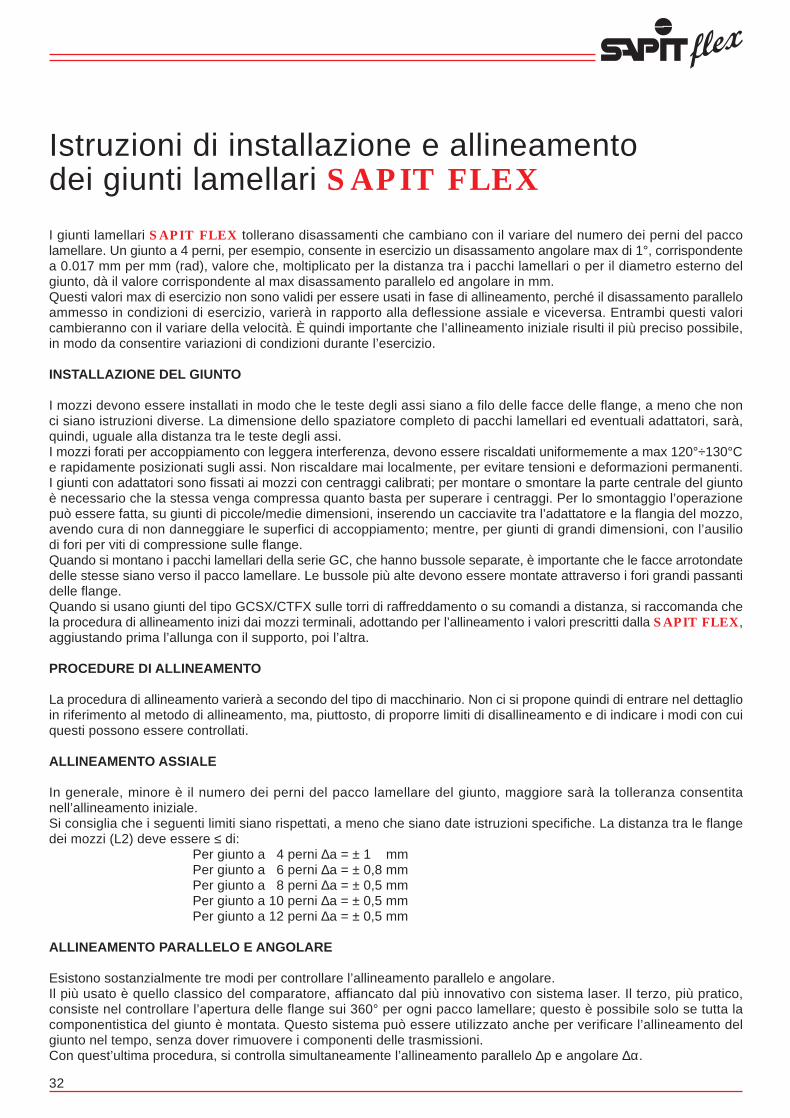
TIPO DEL GIUNTOCOUPLING SIZE
Peso GCSTX-4-FC kg.Weight GCSTX-4-FC kg.
PD2 GCSTX-4-FC kgm2
Inertia PD2 GCSTX-4-FC kgm2
Coppia di serraggio dadi pacchi lamellari NmNuts tightenning torque of element blades Nm
Deflessione assiale +/- mmAxial deflection +/- mm
17
TAB. B
Caratteristiche tecniche / Technical featuresSerie/Ranges GCSTX-4-FC
345-4
60
1,227
180
8,0
255-4
45
0,714
180
7,0
160-4
30
0,340
80
6,2
125-4
22
0,220
80
4,8
80-4
14,5
0,095
45
4,2
32
Istruzioni di installazione e allineamentodei giunti lamellari SAPIT FLEXI giunti lamellari SAPIT FLEX tollerano disassamenti che cambiano con il variare del numero dei perni del paccolamellare. Un giunto a 4 perni, per esempio, consente in esercizio un disassamento angolare max di 1°, corrispondentea 0.017 mm per mm (rad), valore che, moltiplicato per la distanza tra i pacchi lamellari o per il diametro esterno delgiunto, dà il valore corrispondente al max disassamento parallelo ed angolare in mm.Questi valori max di esercizio non sono validi per essere usati in fase di allineamento, perché il disassamento paralleloammesso in condizioni di esercizio, varierà in rapporto alla deflessione assiale e viceversa. Entrambi questi valoricambieranno con il variare della velocità. È quindi importante che l’allineamento iniziale risulti il più preciso possibile,in modo da consentire variazioni di condizioni durante l’esercizio.
INSTALLAZIONE DEL GIUNTO
I mozzi devono essere installati in modo che le teste degli assi siano a filo delle facce delle flange, a meno che nonci siano istruzioni diverse. La dimensione dello spaziatore completo di pacchi lamellari ed eventuali adattatori, sarà,quindi, uguale alla distanza tra le teste degli assi.I mozzi forati per accoppiamento con leggera interferenza, devono essere riscaldati uniformemente a max 120°÷130°Ce rapidamente posizionati sugli assi. Non riscaldare mai localmente, per evitare tensioni e deformazioni permanenti.I giunti con adattatori sono fissati ai mozzi con centraggi calibrati; per montare o smontare la parte centrale del giuntoè necessario che la stessa venga compressa quanto basta per superare i centraggi. Per lo smontaggio l’operazionepuò essere fatta, su giunti di piccole/medie dimensioni, inserendo un cacciavite tra l’adattatore e la flangia del mozzo,avendo cura di non danneggiare le superfici di accoppiamento; mentre, per giunti di grandi dimensioni, con l’ausiliodi fori per viti di compressione sulle flange.Quando si montano i pacchi lamellari della serie GC, che hanno bussole separate, è importante che le facce arrotondatedelle stesse siano verso il pacco lamellare. Le bussole più alte devono essere montate attraverso i fori grandi passantidelle flange.Quando si usano giunti del tipo GCSX/CTFX sulle torri di raffreddamento o su comandi a distanza, si raccomanda chela procedura di allineamento inizi dai mozzi terminali, adottando per l’allineamento i valori prescritti dalla SAPIT FLEX,aggiustando prima l’allunga con il supporto, poi l’altra.
PROCEDURE DI ALLINEAMENTO
La procedura di allineamento varierà a secondo del tipo di macchinario. Non ci si propone quindi di entrare nel dettaglioin riferimento al metodo di allineamento, ma, piuttosto, di proporre limiti di disallineamento e di indicare i modi con cuiquesti possono essere controllati.
ALLINEAMENTO ASSIALE
In generale, minore è il numero dei perni del pacco lamellare del giunto, maggiore sarà la tolleranza consentitanell’allineamento iniziale.Si consiglia che i seguenti limiti siano rispettati, a meno che siano date istruzioni specifiche. La distanza tra le flangedei mozzi (L2) deve essere ≤ di:
Per giunto a 4 perni ∆a = ± 1 mmPer giunto a 6 perni ∆a = ± 0,8 mmPer giunto a 8 perni ∆a = ± 0,5 mmPer giunto a 10 perni ∆a = ± 0,5 mmPer giunto a 12 perni ∆a = ± 0,5 mm
ALLINEAMENTO PARALLELO E ANGOLARE
Esistono sostanzialmente tre modi per controllare l’allineamento parallelo e angolare.Il più usato è quello classico del comparatore, affiancato dal più innovativo con sistema laser. Il terzo, più pratico,consiste nel controllare l’apertura delle flange sui 360° per ogni pacco lamellare; questo è possibile solo se tutta lacomponentistica del giunto è montata. Questo sistema può essere utilizzato anche per verificare l’allineamento delgiunto nel tempo, senza dover rimuovere i componenti delle trasmissioni.Con quest’ultima procedura, si controlla simultaneamente l’allineamento parallelo ∆p e angolare ∆α.
NOTE:A) I pesi e i PD2 sono calcolati con mozzi in acciaio, dimensioni a catalogo e con foro “d” min.B) La rigidità torsionale è data per dimensioni a catalogo e si riferisce ai particolari compresi tra le flange dei mozzi (spaziatore, pacchi lamellari, bulloneria, eventuali adattatori, ecc.).C) Il disassamento assiale ammissibile è in funzione del disassamento parallelo o viceversa.D) Prima di serrare i dadi che bloccano i pacchi lamellari è opportuno passare un velo d’olio sulle rispettive filettature.E) Le velocità massime ammesse (Giri/1’) sono calcolate con i componenti principali (mozzi, eventuali adattatori, spaziatori, ecc.) costruiti in acciaio al carbonio e con dimensioni a catalogo. Per velocità di esercizio superiori o sono usati acciai speciali o vengono eseguiti speciali studi.
Dati e dimensioni contenuti in questo catalogo possono essere variati senza preavviso.
NOTES:A) Weight and inertia are calculated with steel hubs, standard dimensions and with min bore “d”.B) Torsional stiffness is given between hub flanges for standard dimensions (spacer, elements blades, bolts, adaptors, etc.).C) Allowable axial misalignment is related to parallel misalignment and viceversa.D) Before bolts tightening to lock the element blades it is advisable to apply a light oil film on the related threads.E) Max speed (RPM) are calculated with the main components (hubs, adaptors, spacers, etc.) manufactured in carbon steel and with standard dimensions. For higher operational speeds alternative materials or special designs are available.
Figures and dimensions included in this catalogue may be varied without prior advice.
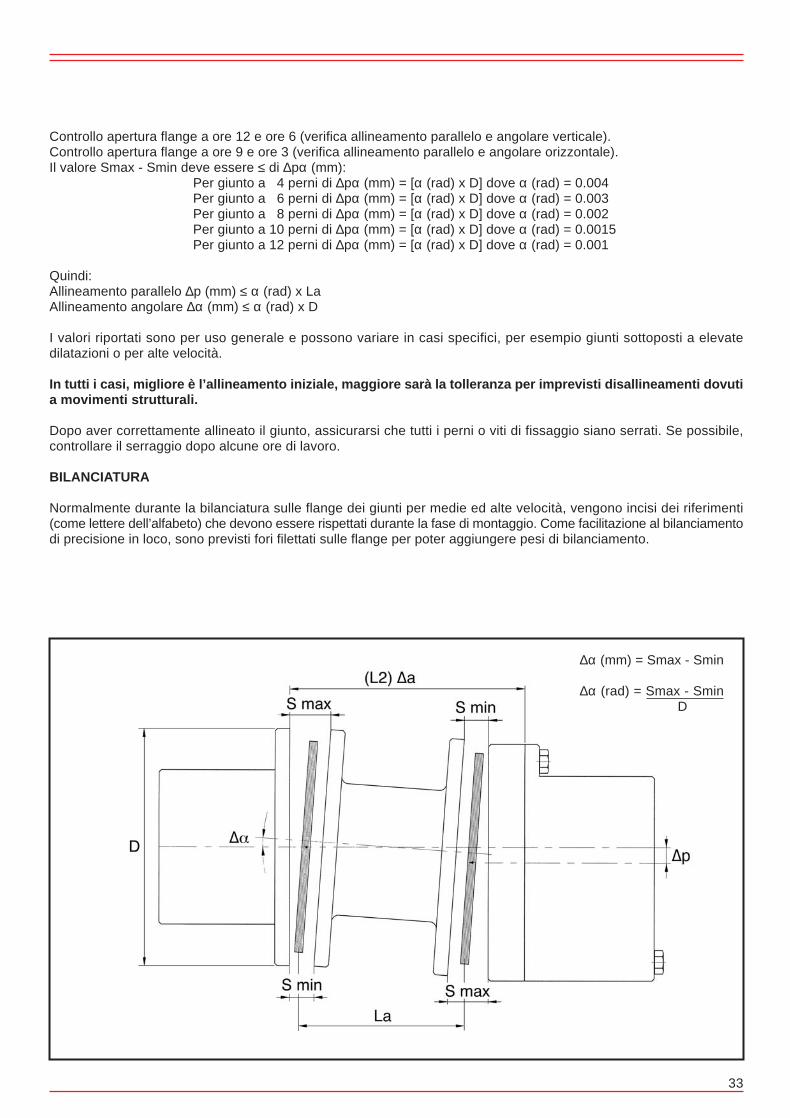
16
Serie/RangesGCSTX-4-FC
CON SPAZIATORE COMPOSTO IN ACCIAIO/ MAT. COMPOSITODa HP 0,08 a HP 0,34 a 1 GIRO/1’WITH COMBINED SPACER IN STEEL/COMPOSITEFrom HP 0,08 to HP 0,34 at 1 RPM
Disassamento angolare max = 1° per elementoMax angular misalignment = 1° each element
Disassamento parallelo max mm = 0.017 x (L3 + S)Max parallel misalignment = 0.017 x (L3 + S)
DIMENSIONI RIFERITE AI TIPI STANDARDPossono essere variate le dimensioni di lunghezza dei mozzi e dello spaziatore
DIMENSIONS REFERRED TO STANDARD VERSIONHubs and spacer lengths can be modified
* Dimensioni ammesse per velocità di esercizionon superiori a 1500 giri/1’* Allowable dimensions for operational speedsnot higher than 1500 RPM
33
80-4
125-4
160-4
255-4
345-4
Potenza trasmis.a 1 giro/1’
Nominal ratingtransmissible at 1 RPM
TIPO
SIZE
Coppia tras.
Nominal Torque
Nm
560
900
1100
1800
2400
HP/n
0,080
0,128
0,157
0,256
0,342
KW/n
0,059
0,094
0,119
0,188
0,251
TAB. A
72
82
105
118
137
M
mm
3277
3877
3873
4269
4668
L3
mm
3300
3900
3900
4300
4700
L2
mm
11,5
11,5
13,5
15,5
16
S
mm
60
70
90
100
115
L1
mm
50
58
75
85
95
dmax
mm
17
17
17
20
20
dmin
mm
3420
4040
4080
4500
4930
L
mm
126
143
168
194
214
D
mm
Controllo apertura flange a ore 12 e ore 6 (verifica allineamento parallelo e angolare verticale).Controllo apertura flange a ore 9 e ore 3 (verifica allineamento parallelo e angolare orizzontale).Il valore Smax - Smin deve essere ≤ di ∆pα (mm):
Per giunto a 4 perni di ∆pα (mm) = [α (rad) x D] dove α (rad) = 0.004Per giunto a 6 perni di ∆pα (mm) = [α (rad) x D] dove α (rad) = 0.003Per giunto a 8 perni di ∆pα (mm) = [α (rad) x D] dove α (rad) = 0.002Per giunto a 10 perni di ∆pα (mm) = [α (rad) x D] dove α (rad) = 0.0015Per giunto a 12 perni di ∆pα (mm) = [α (rad) x D] dove α (rad) = 0.001
Quindi:Allineamento parallelo ∆p (mm) ≤ α (rad) x LaAllineamento angolare ∆α (mm) ≤ α (rad) x D
I valori riportati sono per uso generale e possono variare in casi specifici, per esempio giunti sottoposti a elevatedilatazioni o per alte velocità.
In tutti i casi, migliore è l’allineamento iniziale, maggiore sarà la tolleranza per imprevisti disallineamenti dovutia movimenti strutturali.
Dopo aver correttamente allineato il giunto, assicurarsi che tutti i perni o viti di fissaggio siano serrati. Se possibile,controllare il serraggio dopo alcune ore di lavoro.
BILANCIATURA
Normalmente durante la bilanciatura sulle flange dei giunti per medie ed alte velocità, vengono incisi dei riferimenti(come lettere dell’alfabeto) che devono essere rispettati durante la fase di montaggio. Come facilitazione al bilanciamentodi precisione in loco, sono previsti fori filettati sulle flange per poter aggiungere pesi di bilanciamento.
∆α (mm) = Smax - Smin
∆α (rad) = Smax - Smin D

Procedura di montaggio pacchi lamellari
A) Tutti i giunti SAPIT FLEX hanno, come peculiarità, ma ad eccezione della serie RH, la possibilità di sostituire gli elementi flessibili ed eventuali spaziatori centrali senza rimuovere le macchine accoppiate.
B) Esempi di montaggio e smontaggio pacchi lamellari giunti serie HBX - HBSX - HBSX/AH - HBSX/RH - HPX - HPSX - BE
Figura 1 = Schema di montaggio pacco lamellareFigura 1a = Schema di montaggio pacco lamellare con bullone corto, giunti serie HBSX/AHFigura 1b = Schema di montaggio pacco lamellare con bullone corto, giunti serie HBSX/RH
C) Esempi di montaggio e smontaggio pacchi lamellari giunti serie GCX - GCSX - GCSX/AH - GCSTX - GCSTX/CTFX - GCSTX/FC
Figura 2 = Schema di montaggio pacco lamellareFigura 2a = Schema di montaggio pacco lamellare giunti serie GCSX/AHFigura 2b = Schema di montaggio pacco lamellare con tirante
TIPO DEL GIUNTOCOUPLING SIZE
Peso GCSX/CTFX-4 kg.Weight GCSX/CTFX-4 kg.
PD2 GCSX/CTFX-4 kgm2
Inertia PD2 GCSX/CTFX-4 kgm2
Rigidità torsionale GCSX/CTFX-4 Nm/rad x 106
Torsional Stiffness GCSX/CTFX-4XNm/rad x 106
Coppia di serraggio dadi pacchi lamellari NmNuts tightenning torque of element blades Nm
Deflessione assiale +/- mmAxial deflection +/- mm
15
TAB. B
800-4
217
5,5667
103,986
650
15
Caratteristiche tecniche / Technical featuresSerie/Ranges GCSX/CTFX-4
560-4
172
3,1226
98,689
270
13,5
345-4
134
2,0430
91,429
180
12,0
255-4
88
0,9927
31,784
180
10,5
160-4
57
0,4387
15,078
80
9,3
125-4
44
0,2620
14,833
80
7,2
80-4
26
0,1051
5,386
45
6,3
34
Figura 2 Figura 2a Figura 2b
Figura 1 Figura 1a Figura 1b
NOTE:A) I pesi e i PD2 sono calcolati con mozzi in acciaio, dimensioni a catalogo e con foro “d” min.B) La rigidità torsionale è data per dimensioni a catalogo e si riferisce ai particolari compresi tra le flange dei mozzi (spaziatore, pacchi lamellari, bulloneria, eventuali adattatori, ecc.).C) Il disassamento assiale ammissibile è in funzione del disassamento parallelo o viceversa.D) Prima di serrare i dadi che bloccano i pacchi lamellari è opportuno passare un velo d’olio sulle rispettive filettature.E) Le velocità massime ammesse (Giri/1’) sono calcolate con i componenti principali (mozzi, eventuali adattatori, spaziatori, ecc.) costruiti in acciaio al carbonio e con dimensioni a catalogo. Per velocità di esercizio superiori o sono usati acciai speciali o vengono eseguiti speciali studi.
Dati e dimensioni contenuti in questo catalogo possono essere variati senza preavviso.
NOTES:A) Weight and inertia are calculated with steel hubs, standard dimensions and with min bore “d”.B) Torsional stiffness is given between hub flanges for standard dimensions (spacer, elements blades, bolts, adaptors, etc.).C) Allowable axial misalignment is related to parallel misalignment and viceversa.D) Before bolts tightening to lock the element blades it is advisable to apply a light oil film on the related threads.E) Max speed (RPM) are calculated with the main components (hubs, adaptors, spacers, etc.) manufactured in carbon steel and with standard dimensions. For higher operational speeds alternative materials or special designs are available.
Figures and dimensions included in this catalogue may be varied without prior advice.
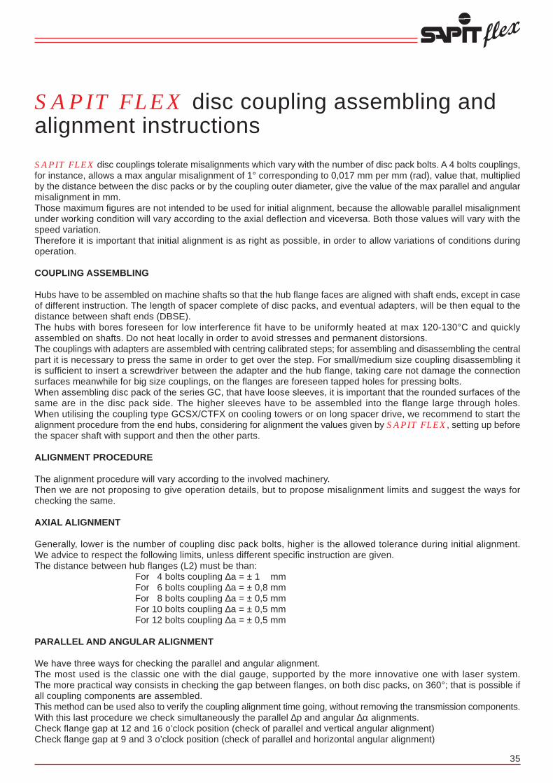
14
Serie/RangesGCSX/CTFX-4
CON SPAZIATORE COMPOSTO IN ACCIAIO E SUPPORTO CENTRALEDa HP 0,08 a HP 0,8 a 1 GIRO/1’WITH COMBINED SPACER IN STEEL AND CENTRAL BEARINGFrom HP 0,08 to HP 0,8 at 1 RPM
Disassamento angolare max = 1° per elementoMax angular misalignment = 1° each element
Disassamento parallelo max mm = 0.017 x (L - S)Max parallel misalignment = 0.017 x (L - S)
DIMENSIONI RIFERITE AI TIPI STANDARD - Possono essere variate le dimensioni di lunghezza dei mozzi e dello spaziatoreDIMENSIONS REFERRED TO STANDARD VERSION - Hubs and spacer lenghts can be modified
* Dimensioni ammesse per velocità di esercizionon superiori a 1500 giri/1’* Allowable dimensions for operational speedsnot higher than 1500 RPM
35
80-4
125-4
160-4
255-4
345-4
560-4
800-4
Potenza trasmis.a 1 giro/1’
Nominal ratingtransmissible at 1 RPM
TIPO
SIZE
Coppia tras.
Nominal Torque
Nm
560
900
1100
1800
2400
3900
5600
HP/n
0,080
0,128
0,157
0,256
0,342
0,555
0,797
KW/n
0,059
0,094
0,119
0,188
0,251
0,408
0,586
TAB. A
72
82
105
118
137
156
168
M
mm
2100
2625
2640
2990
3335
3385
3385
L5
mm
120
130
150
170
180
220
235
L4
mm
1957
2467
2468
2809
3148
3142
3126
L3
mm
1980
2490
2495
2840
3180
3180
3180
L2
mm
11,5
11,5
13,5
15,5
16
19
27
S
mm
60
70
85
100
115
130
140
L1
mm
50
58
75
85
95
110
120
dmax
mm
17
17
17
20
20
20
20
dmin
mm
4200
5245
5395
6000
6695
6785
6800
L
mm
126
143
168
194
214
246
275
D
mm
80-4
125-4
160-4
255-4
345-4
560-4
800-4
Supporto S.K.F. completoComplete S.K.F. bearing
TIPOTYPE
27
30
30
32
32
40
45
Rmm
16 M
16 M
16 M
20 M
20 M
24 M
24 M
Ømm
210
210
230
260
260
320
350
Fmm
70
70
80
95
95
112
125
Hmm
50
55
60
70
75
90
100
d1mm
SNH 511 TA + 1211 K + H 211
SNH 512 TA + 1212 K + H 212
SNH 513 TA + 1213 K + H 213
SNH 516 TA + 1216 K + H 216
SNH 517 TA + 1217 K + H 217
SNH 520 TA + 1220 K + H 220
SNH 522 TA + 1222 K + H 222
SAPIT FLEX disc coupling assembling andalignment instructions
SAPIT FLEX disc couplings tolerate misalignments which vary with the number of disc pack bolts. A 4 bolts couplings,for instance, allows a max angular misalignment of 1° corresponding to 0,017 mm per mm (rad), value that, multipliedby the distance between the disc packs or by the coupling outer diameter, give the value of the max parallel and angularmisalignment in mm.Those maximum figures are not intended to be used for initial alignment, because the allowable parallel misalignmentunder working condition will vary according to the axial deflection and viceversa. Both those values will vary with thespeed variation.Therefore it is important that initial alignment is as right as possible, in order to allow variations of conditions duringoperation.
COUPLING ASSEMBLING
Hubs have to be assembled on machine shafts so that the hub flange faces are aligned with shaft ends, except in caseof different instruction. The length of spacer complete of disc packs, and eventual adapters, will be then equal to thedistance between shaft ends (DBSE).The hubs with bores foreseen for low interference fit have to be uniformly heated at max 120-130°C and quicklyassembled on shafts. Do not heat locally in order to avoid stresses and permanent distorsions.The couplings with adapters are assembled with centring calibrated steps; for assembling and disassembling the centralpart it is necessary to press the same in order to get over the step. For small/medium size coupling disassembling itis sufficient to insert a screwdriver between the adapter and the hub flange, taking care not damage the connectionsurfaces meanwhile for big size couplings, on the flanges are foreseen tapped holes for pressing bolts.When assembling disc pack of the series GC, that have loose sleeves, it is important that the rounded surfaces of thesame are in the disc pack side. The higher sleeves have to be assembled into the flange large through holes.When utilising the coupling type GCSX/CTFX on cooling towers or on long spacer drive, we recommend to start thealignment procedure from the end hubs, considering for alignment the values given by SAPIT FLEX, setting up beforethe spacer shaft with support and then the other parts.
ALIGNMENT PROCEDURE
The alignment procedure will vary according to the involved machinery.Then we are not proposing to give operation details, but to propose misalignment limits and suggest the ways forchecking the same.
AXIAL ALIGNMENT
Generally, lower is the number of coupling disc pack bolts, higher is the allowed tolerance during initial alignment.We advice to respect the following limits, unless different specific instruction are given.The distance between hub flanges (L2) must be than:
For 4 bolts coupling ∆a = ± 1 mmFor 6 bolts coupling ∆a = ± 0,8 mmFor 8 bolts coupling ∆a = ± 0,5 mmFor 10 bolts coupling ∆a = ± 0,5 mmFor 12 bolts coupling ∆a = ± 0,5 mm
PARALLEL AND ANGULAR ALIGNMENT
We have three ways for checking the parallel and angular alignment.The most used is the classic one with the dial gauge, supported by the more innovative one with laser system.The more practical way consists in checking the gap between flanges, on both disc packs, on 360°; that is possible ifall coupling components are assembled.This method can be used also to verify the coupling alignment time going, without removing the transmission components.With this last procedure we check simultaneously the parallel ∆p and angular ∆α alignments.Check flange gap at 12 and 16 o’clock position (check of parallel and vertical angular alignment)Check flange gap at 9 and 3 o’clock position (check of parallel and horizontal angular alignment)

TIPO DEL GIUNTOCOUPLING SIZE
Peso GCSTX-4 kg.Weight GCSTX-4 kg.
PD2 GCSTX-4 kgm2
Inertia PD2 GCSTX-4 kgm2
Rigidità torsionale GCSTX-4 Nm/rad x 106
Torsional Stiffness GCSTX-4 Nm/rad x 106
Coppia di serraggio dadi pacchi lamellari NmNuts tightenning torque of element blades Nm
Deflessione assiale +/- mmAxial deflection +/- mm
13
TAB. B
800-4
150
3,3917
217,978
650
10,0
Caratteristiche tecniche / Technical featuresSerie/Ranges GCSTX-4
560-4
122
2,2989
194,729
270
9,0
345-4
100
1,6074
174,716
180
8,0
255-4
65
0,7400
64,452
180
7,0
160-4
42
0,3196
31,000
80
6,2
125-4
34
0,2033
30,117
80
4,8
80-4
20,0
0,0779
10,987
45
4,2
36
The values Smax - Smin must be ≤ of ∆pα (mm):For 4 bolts coupling of ∆pα (mm) = [α (rad) x D] where α (rad) = 0.004 mmFor 6 bolts coupling of ∆pα (mm) = [α (rad) x D] where α (rad) = 0.003 mmFor 8 bolts coupling of ∆pα (mm) = [α (rad) x D] where α (rad) = 0.002 mmFor 10 bolts coupling of ∆pα (mm) = [α (rad) x D] where α (rad) = 0.0015 mmFor 12 bolts coupling of ∆pα (mm) = [α (rad) x D] where α (rad) = 0.001 mm
Then:Parallel alignment ∆p (mm) ≤ (rad) x LaAngular alignment ∆α (mm) ≤ (rad) x D
The stated values are for general use and can vary in specific cases, for instance for couplings working at high dilatationsor speeds.
In any case, better is the initial alignment, higher is the tolerance at unforeseen misalignment due to structuremovements.
After having properly aligned the coupling, make sure that all the bolts or fixing screws are tightened. If possible checkthe tightening after some hours of operation too.
BALANCING
Usually during balancing on flanges, of couplings for medium and high speeds, are printed some references (e.g.alphabetic letters) to be respected when assembling.For making easier the precision balancing on site we foresee some tapped hole on flanges in order to have the possibilityto add balancing weights.
NOTE:A) I pesi e i PD2 sono calcolati con mozzi in acciaio, dimensioni a catalogo e con foro “d” min.B) La rigidità torsionale è data per dimensioni a catalogo e si riferisce ai particolari compresi tra le flange dei mozzi (spaziatore, pacchi lamellari, bulloneria, eventuali adattatori, ecc.).C) Il disassamento assiale ammissibile è in funzione del disassamento parallelo o viceversa.D) Prima di serrare i dadi che bloccano i pacchi lamellari è opportuno passare un velo d’olio sulle rispettive filettature.E) Le velocità massime ammesse (Giri/1’) sono calcolate con i componenti principali (mozzi, eventuali adattatori, spaziatori, ecc.) costruiti in acciaio al carbonio e con dimensioni a catalogo. Per velocità di esercizio superiori o sono usati acciai speciali o vengono eseguiti speciali studi.
Dati e dimensioni contenuti in questo catalogo possono essere variati senza preavviso.
NOTES:A) Weight and inertia are calculated with steel hubs, standard dimensions and with min bore “d”.B) Torsional stiffness is given between hub flanges for standard dimensions (spacer, elements blades, bolts, adaptors, etc.).C) Allowable axial misalignment is related to parallel misalignment and viceversa.D) Before bolts tightening to lock the element blades it is advisable to apply a light oil film on the related threads.E) Max speed (RPM) are calculated with the main components (hubs, adaptors, spacers, etc.) manufactured in carbon steel and with standard dimensions. For higher operational speeds alternative materials or special designs are available.
Figures and dimensions included in this catalogue may be varied without prior advice.
∆α (mm) = Smax - Smin
∆α (rad) = Smax - Smin D

Assembling procedure of disc packs
A) All SAPIT FLEX‘s couplings have, as a peculiarity, (except the series RH) the possibility to change the flexible elements and eventual centre spacers without moving the connected machines.
B) Examples of disc pack assembling and disassembling of the coupling series HBX - HBSX - HBSX/AH - HBSX/RH - HPX - HPSX - BE
Figure 1 = Disc pack assembling diagramFigure 1a = Short bolt disc pack assembling diagram, coupling series HBSX/AHFigure 1b = Short bolt disc pack assembling diagram, coupling series HBSX/RH
C) Examples of disc pack assembling and disassembling of the coupling series GCX - GCSX - GCSX/AH - GCSTX - GCSTX/CTFX - GCSTX/FC
Figure 2 = Disc pack assembling diagramFigure 2a = Disc pack assembling diagram, coupling series GCSX/AHFigure 2b = Disc pack assembling diagram, with tie rod
12
Serie/RangesGCSTX-4
CON SPAZIATORE COMPOSTO IN ACCIAIODa HP 0,08 a HP 0,8 a 1 GIRO/1’WITH COMBINED SPACER IN STEELFrom HP 0,08 to HP 0,8 at 1 RPM
80-4
125-4
160-4
255-4
345-4
560-4
800-4
Potenza trasmis.a 1 giro/1’
Nominal ratingtransmissible at 1 RPM
TIPO
SIZE
Coppia tras.
Nominal Torque
Nm
560
900
1100
1800
2400
3900
5600
HP/n
0,080
0,128
0,157
0,256
0,342
0,555
0,797
KW/n
0,059
0,094
0,119
0,188
0,251
0,408
0,586
TAB. A
72
82
105
118
137
156
168
M
mm
1957
2467
2468
2809
3148
3142
3126
L3
mm
1980
2490
2495
2840
3180
3180
3180
L2
mm
11,5
11,5
13,5
15,5
16
19
27
S
mm
60
70
90
100
115
130
140
L1
mm
50
58
75
85
95
110
120
dmax
mm
17
17
17
20
20
20
20
dmin
mm
2100
2630
2675
3040
3410
3440
3460
L
mm
126
143
168
194
214
246
275
D
mm
Disassamento angolare max = 1° per elementoMax angular misalignment = 1° each element
Disassamento parallelo max mm = 0.017 x (L3 + S)Max parallel misalignment = 0.017 x (L3 + S)
DIMENSIONI RIFERITE AI TIPI STANDARDPossono essere variate le dimensioni di lunghezza dei mozzi e dello spaziatore
DIMENSIONS REFERRED TO STANDARD VERSIONHubs and spacer lenghts can be modified
* Dimensioni ammesse per velocità di esercizionon superiori a 1500 giri/1’* Allowable dimensions for operational speedsnot higher than 1500 RPM
37
Figure 2 Figure 2a Figure 2b
Figure 1 Figure 1a Figure 1b

TIPO DEL GIUNTOCOUPLING SIZE
Peso GCSX-AH kg.Weight GCSX-AH kg.
Peso GCSX-AH-ALH kg.Weight GCSX-AH-ALH kg.
Peso GCSX-ALH kg.Weight GCSX-ALH kg.
Peso GCSX-AH-M kg.Weight GCSX-AH-M kg.
Peso GCSX-ALH-M kg.Weight GCSX-ALH-M kg.
PD2 GCSX-AH kgm2
Inertia PD2 GCSX-AH kgm2
PD2 GCSX-AH-ALH kgm2
Inertia PD2 GCSX-AH-ALH kgm2
PD2 GCSX-ALH kgm2
Inertia PD2 GCSX-ALH kgm2
PD2 GCSX-AH-M kgm2
Inertia PD2 GCSX-AH-M kgm2
PD2 GCSX-ALH-M kgm2
Inertia PD2 GCSX-ALH-M kgm2
Rigidità torsionale GCSX-AH • GCSX-AH-ALH • GCSX-ALH Nm/rad x 106
Torsional Stiffness GCSX-AH • GCSX-AH-ALH • GCSX-ALH Nm/rad x 106
Rigidità torsionale GCSX-AH-M • GCSX-ALH-M Nm/rad x 106
Torsional Stiffness GCSX-AH-M • GCSX-ALH-M Nm/rad x 106
Coppia di serraggio dadi pacchi lamellari NmNuts tightenning torque of element blades Nm
Coppia di serraggio bulloni adattatori NmNuts tightenning torque of adaptator Nm
Deflessione assiale +/- mmAxial deflection +/- mm
Velocità ammessa giri/1’Max speed RPM
11
TAB. B
345-4
66,0
54,0
65,0
88,0
77,0
1,4657
1,0363
2,1818
1,3230
1,7524
1,0546
1,1125
180
85
8,0
3000
Caratteristiche tecniche / Technical featuresSerie/Ranges GCSX-4-AH
255-4
49,0
40,0
66,0
48,0
57,0
0,9026
0,6406
1,3428
0,8188
1,0808
0,8388
0,8309
180
85
7,0
3000
160-4
32,0
26,0
43,0
31,0
27,0
0,4391
0,3064
0,6557
0,3903
0,5230
0,5023
0,4983
80
50
5,0
3600
125-4
19,5
15,7
26,5
19,0
22,6
0,1977
0,1450
0,2925
0,1717
0,2348
0,4091
0,4042
80
50
4,8
3800
80-4
13,0
10,6
17,8
13,0
15,4
0,1029
0,0738
0,1524
0,0942
0,1233
0,2492
0,2472
45
25
4,2
4000
36-4
7,2
5,8
9,8
7,1
8,5
0,0381
0,0268
0,0567
0,0341
0,0454
0,1265
0,1256
23
10
3,6
4200
26-4
5,4
4,3
7,4
5,3
6,4
0,0227
0,0162
0,0338
0,0208
0,0273
0,0804
0,0795
23
10
3,2
4300
13-4
3,6
2,8
4,9
3,3
4,1
0,0117
0,0082
0,0174
0,0104
0,0139
0,0549
0,0540
10
10
2,8
4500
9-4
1,7
1,4
2,5
1,8
2,1
0,0038
0,0028
0,0058
0,0038
0,0048
0,0314
0,0304
10
10
2
5000
38
GIUNTO CON ADATTATORE MAGGIORATO
COUPLING WITH OVERSIZED ADAPTER
Applicazioni speciali dei giunti lamellariSpecial applications of disc couplings
Questi sono alcuni esempi che illustrano applicazioni per cui vengono prodotti i giunti SAPIT FLEX.Naturalmente è possibile combinare varie soluzioni o modificare i modelli in modo da ottenererisultati idonei alle varie esigenze.Lo spazio non consente di includere tutte le innumerevoli applicazioni e, quindi, se un particolareadattamento non è illustrato ci si rivolga al nostro servizio tecnico che è a disposizione perqualsiasi necessità.
Here under are shown few examples of disc couplings commercialized by SAPIT FLEX forspecial applications.It is possible to combine different solutions or to modify the types in order to comply with theend user requirements.Many other special disc couplings applications are regularly commercialized by SAPIT FLEXwhich for space reason are not shown in this catalogue. For any information and assistanceplease refer to our technical service.
NOTE:A) I pesi e i PD2 sono calcolati con mozzi in acciaio, dimensioni a catalogo e con foro “d” min.B) La rigidità torsionale è data per dimensioni a catalogo e si riferisce ai particolari compresi tra le flange dei mozzi (spaziatore, pacchi lamellari, bulloneria, eventuali adattatori, ecc.).C) Il disassamento assiale ammissibile è in funzione del disassamento parallelo o viceversa.D) Prima di serrare i dadi che bloccano i pacchi lamellari è opportuno passare un velo d’olio sulle rispettive filettature.E) Le velocità massime ammesse (Giri/1’) sono calcolate con i componenti principali (mozzi, eventuali adattatori, spaziatori, ecc.) costruiti in acciaio al carbonio e con dimensioni a catalogo. Per velocità di esercizio superiori o sono usati acciai speciali o vengono eseguiti speciali studi.
Dati e dimensioni contenuti in questo catalogo possono essere variati senza preavviso.
NOTES:A) Weight and inertia are calculated with steel hubs, standard dimensions and with min bore “d”.B) Torsional stiffness is given between hub flanges for standard dimensions (spacer, elements blades, bolts, adaptors, etc.).C) Allowable axial misalignment is related to parallel misalignment and viceversa.D) Before bolts tightening to lock the element blades it is advisable to apply a light oil film on the related threads.E) Max speed (RPM) are calculated with the main components (hubs, adaptors, spacers, etc.) manufactured in carbon steel and with standard dimensions. For higher operational speeds alternative materials or special designs are available.
Figures and dimensions included in this catalogue may be varied without prior advice.
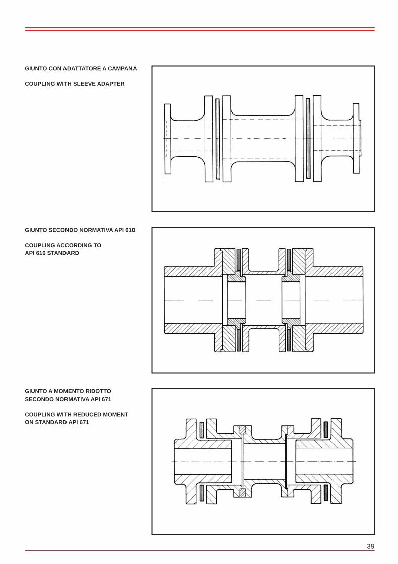
10
Serie/Ranges GCSX-4-AH
CON SPAZIATORE E ADATTATORI A 4 PERNIDa HP 0,009 a HP 0,34 a 1 GIRO/1’4 BOLTS WITH SPACER AND ADAPTORSFrom HP 0,009 to HP 0,34 at 1 RPM
9-4
13-4
26-4
36-4
80-4
125-4
160-4
255-4
345-4
Potenza trasmis.a 1 giro/1’
Nominal ratingtransmissible at 1 RPM
TIPO
SIZE
Coppia tras.
Nominal Torque
Nm
60
90
180
250
560
900
1100
1800
2400
HP/n
0,009
0,013
0,026
0,036
0,080
0,128
0,157
0,256
0,342
KW/n
0,007
0,009
0,019
0,026
0,059
0,094
0,119
0,188
0,251
TAB. A
70
71
82
92
106
131
135
172
196
L2
mm
7,5
7,0
8,0
8,5
11,5
11,5
13,5
15,5
16,0
S
mm
25
40
45
50
60
70
90
100
115
L1
mm
40
55
65
75
90
100
120
135
150
d2max
mm
28
38
46
53
65
70
90
100
115
d1max
mm
23
32
35
42
50
58
75
85
95
dmax
mm
13
13
13
13
17
17
17
20
20
d:d1:d2min
mm
135
166
189
209
249
297
342
405
459
LA
mm
120
151
172
192
226
271
315
372
426
L
mm
67
81
93
104
126
143
168
194
214
D
mm
39
GIUNTO CON ADATTATORE A CAMPANA
COUPLING WITH SLEEVE ADAPTER
GIUNTO SECONDO NORMATIVA API 610
COUPLING ACCORDING TOAPI 610 STANDARD
GIUNTO A MOMENTO RIDOTTOSECONDO NORMATIVA API 671
COUPLING WITH REDUCED MOMENTON STANDARD API 671
Disassamento angolare max = 1° per elementoMax angular misalignment = 1° each element
Disassamento parallelo max mm = 0.017 x (L3 + S)Max parallel misalignment = 0.017 x (L3 + S)
DIMENSIONI RIFERITE AI TIPI STANDARDPossono essere variate le dimensioni di lunghezza dei mozzie dello spaziatoreDIMENSIONS REFERRED TO STANDARD VERSIONHubs and spacer lenghts can be modified
85
86
99
109
129
157
162
205
229
L2A
mm
40
42
49
58
60
82
81
108
131
L3
mm
33
46
50
61
72
82
105
118
137
M
mm
39
53
65
75
90
100
126
144
164
M1
mm
Serie/Ranges GCSX-ALH Serie/Ranges GCSX-AH-M Serie/Ranges GCSX-ALH-M
Serie/Ranges GCSX-AH Serie/Ranges GCSX-AH-ALH

TIPO DEL GIUNTOCOUPLING SIZE
Peso GCSX kg.Weight GCSX kg.
Peso GCX kg.Weight GCX kg.
PD2 GCSX kgm2
Inertia PD2 GCSX kgm2
PD2 GCX kgm2
Inertia PD2 GCX kgm2
Rigidità torsionale GCSX Nm/rad x 106
Torsional Stiffness GCSX Nm/rad x 106
Rigidità torsionale GCX Nm/rad x 106
Torsional Stiffness GCX Nm/rad x 106
Coppia di serraggio dadi pacchi lamellari NmNuts tightenning torque of element blades Nm
Deflessione assiale GCSX +/- mmAxial deflection GCSX +/- mm
Deflessione assiale GCX +/- mmAxial deflection GCX +/- mm
Velocità ammessa giri/1’Max speed RPM
9
TAB. B
800-4
95,0
69,0
2,8312
1,7029
2,9558
9,9277
650
10,0
5,0
3000
Caratteristiche tecniche / Technical featuresSerie/Ranges GCSX-4 • GCX-4
560-4
65,0
50,0
1,4880
0,9482
1,6785
4,7382
270
9,0
4,5
3000
345-4
44
33,5
0,7496
0,4777
1,1321
2,8204
180
8,0
4,0
3000
255-4
32,0
23,5
0,4624
0,2794
0,8466
2,2494
180
7,0
3,5
3000
160-4
21,0
16,0
0,2225
0,1390
0,5062
1,3803
80
6,0
3,0
3600
125-4
12,5
8,5
0,1029
0,0590
0,4140
1,0919
80
4,8
2,4
3800
80-4
8,3
5,7
0,0534
0,0306
0,2521
0,6877
45
4,2
2,1
4000
36-4
4,6
3,2
0,0195
0,0113
0,1275
0,3178
23
3,6
1,8
4200
26-4
3,3
2,2
0,0116
0,0064
0,0814
0,2394
23
3,2
1,6
4300
13-4
2,2
1,5
0,0060
0,0034
0,0549
0,1128
10
2,8
1,4
4500
40
GIUNTO CON LAMELLE A SETTORI
COUPLING WITH SEGMENTALELEMENT BLADES
GIUNTO PER MONTAGGIO VERTICALE
COUPLING FOR VERTICAL ASSEMBLING
GIUNTO CON LIMITATORE ASSIALE
COUPLING WITH AXIAL MOVEMENTLIMITING DEVICE
9-4
1,0
0,6
0,0018
0,0010
0,3139
0,0736
10
2,0
1,0
5000
NOTE:A) I pesi e i PD2 sono calcolati con mozzi in acciaio, dimensioni a catalogo e con foro “d” min.B) La rigidità torsionale è data per dimensioni a catalogo e si riferisce ai particolari compresi tra le flange dei mozzi (spaziatore, pacchi lamellari, bulloneria, eventuali adattatori, ecc.).C) Il disassamento assiale ammissibile è in funzione del disassamento parallelo o viceversa.D) Prima di serrare i dadi che bloccano i pacchi lamellari è opportuno passare un velo d’olio sulle rispettive filettature.E) Le velocità massime ammesse (Giri/1’) sono calcolate con i componenti principali (mozzi, eventuali adattatori, spaziatori, ecc.) costruiti in acciaio al carbonio e con dimensioni a catalogo. Per velocità di esercizio superiori o sono usati acciai speciali o vengono eseguiti speciali studi.
Dati e dimensioni contenuti in questo catalogo possono essere variati senza preavviso.
NOTES:A) Weight and inertia are calculated with steel hubs, standard dimensions and with min bore “d”.B) Torsional stiffness is given between hub flanges for standard dimensions (spacer, elements blades, bolts, adaptors, etc.).C) Allowable axial misalignment is related to parallel misalignment and viceversa.D) Before bolts tightening to lock the element blades it is advisable to apply a light oil film on the related threads.E) Max speed (RPM) are calculated with the main components (hubs, adaptors, spacers, etc.) manufactured in carbon steel and with standard dimensions. For higher operational speeds alternative materials or special designs are available.
Figures and dimensions included in this catalogue may be varied without prior advice.
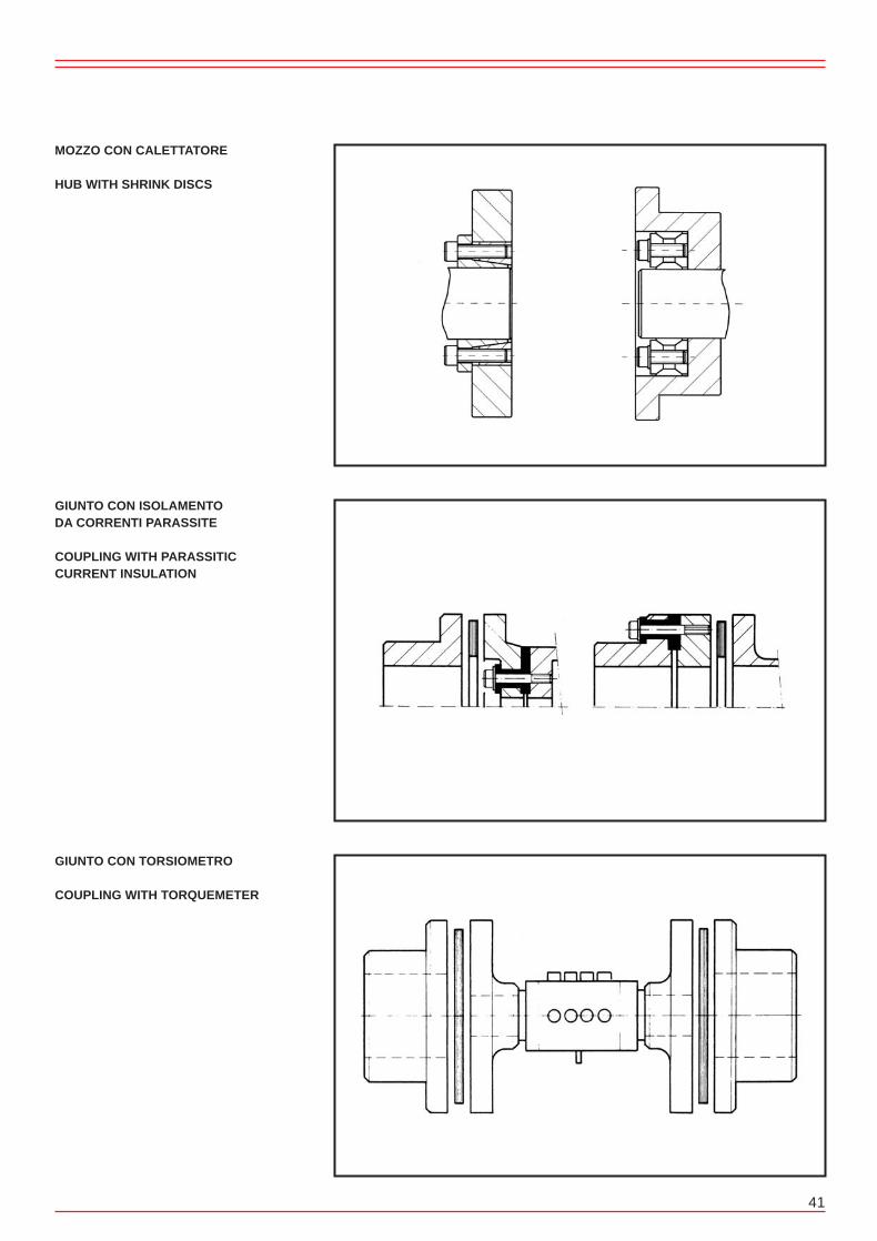
8
Serie/RangesGCSX-4
CON SPAZIATORE A 4 PERNIDa HP 0,009 a HP 0,8 a 1 GIRO/1’4 BOLTS WITH SPACERFrom HP 0,009 to HP 0,8 at 1 RPM
9-4
13-4
26-4
36-4
80-4
125-4
160-4
255-4
345-4
560-4
800-4
Potenza trasmis.a 1 giro/1’
Nominal ratingtransmissible at 1 RPM
TIPO
SIZE
Coppia tras.
Nominal Torque
Nm
60
90
180
250
560
900
1100
1800
2400
3900
5600
HP/n
0,009
0,013
0,026
0,036
0,080
0,128
0,157
0,256
0,342
0,555
0,797
KW/n
0,007
0,009
0,019
0,026
0,059
0,094
0,119
0,188
0,251
0,408
0,586
TAB. A
33
46
50
61
72
82
105
118
137
156
168
M
mm
40
42
49
58
60
82
81
108
131
131
160
L3
mm
55
56
65
75
83
105
108
139
163
169
214
L2
mm
7,5
7
8
8,5
11,5
11,5
13,5
15,5
16
19
27
S
mm
25
40
45
50
60
70
90
100
115
130
140
L1
mm
23
32
35
42
50
58
75
85
95
110
120
dmax
mm
13
13
13
13
17
17
17
20
20
20
20
dmin
mm
57,5
87
98
108,5
131,5
151,5
193,5
215,5
246
279
307
GCXL
mm
105
136
155
175
203
245
288
339
393
429
494
GCSXL
mm
67
81
93
104
126
143
168
194
214
246
275
D
mm
Disassamento angolare max = 1° per elementoMax angular misalignment = 1° each element
Disassamento parallelo max mm = 0.017 x (L3 + S)Max parallel misalignment = 0.017 x (L3 + S)
DIMENSIONI RIFERITE AI TIPI STANDARDPossono essere variate le dimensioni di lunghezza dei mozzie dello spaziatore
DIMENSIONS REFERRED TO STANDARD VERSIONHubs and spacer lengths can be modified
Serie/RangesGCX-4
SENZA SPAZIATORE A 4 PERNIDa HP 0,009 a HP 0,8 a 1 GIRO/1’4 BOLTS WITHOUT SPACERFrom HP 0,009 to HP 0,8 at 1 RPM
Disassamento angolare max = 1°Max angular misalignment = 1°
DIMENSIONI RIFERITE AI TIPI STANDARDPossono essere variate le dimensioni di lunghezza dei mozzi
DIMENSIONS REFERRED TO STANDARD VERSIONHubs and spacer lengths can be modified
41
MOZZO CON CALETTATORE
HUB WITH SHRINK DISCS
GIUNTO CON ISOLAMENTODA CORRENTI PARASSITE
COUPLING WITH PARASSITICCURRENT INSULATION
GIUNTO CON TORSIOMETRO
COUPLING WITH TORQUEMETER


QUESTIONARIO PER LA SELEZIONE DEI GIUNTIDETAILS FOR COUPLINGS SELECTION
2 47
Note:
- Le serie HBX-GCX-HPX ad articolazione sempliceformate da due mozzi ed un pacco lamellare consentonoun disassamento angolare ed assiale, ma non parallelo;per questo il loro impiego è subordinato al perfettoallineamento tra le macchine motrice e condotta.Normalmente questi giunti vengono usati in coppiadistanziati tra loro da un albero, così da riportare latrasmissione in condizione di doppia articolazione.- Le serie GCSTX-GCSX-CTFX sono una variante dellaserie GCSX e sono state realizzate in particolar modoper essere impiegate su torri di raffreddamento. Perquesto utilizzo le estremità dello spaziatore sono chiuseda apposite calotte che non consentono l’ingresso diacqua e vapori e la conseguente formazione di ossidoall’interno. Le tabelle dimensionali relative alla serie digiunti per torri di raffreddamento riportano le lunghezzemax dello spaziatore per velocità di esercizio di 1500RPM; per velocità superiori consultare il ns. ufficio tecnico.- La serie GCSTX-FC con spaziatore in materialecomposito, studiata e realizzata per torri di raffreddamento,consente una riduzione di peso di circa il 70%, quindi èdi facile installazione e permette di raggiungere lunghezzedi spaziatore fino a sei metri senza supporti intermedi.Le tabelle dimensionali relative alla serie di giunti pertorri di raffreddamento riportano le lughezze max dellospaziatore per velocità di esercizio di 1500 RPM; pervelocità superiori consultare il ns. ufficio tecnico. Èpossibile corredare questa serie di giunti con un sistemadi antiritorno da applicare al mozzo lato motore checonsente una rotazione unidirezionale.- Le serie HBSX/AH-GCSX/AH con adattatori e mozzimaggiorati consentono al giunto di avere dei mozzi conuna capacità di foratura maggiore (d max). La loroparticolare configurazione consente di effettuare labilanciatura del gruppo centrale assiemato (adattatori-pacchi lamellari e spaziatore) senza doverlo smontare;questo permette di ottenere un alto grado di ripetibilitàdi bilanciatura.- La serie HBSX/RH con mozzi rovesciati e spaziatorediviso in due metà è stata studiata per realizzare ungiunto lamellare perfettamente intercambiabile nellafunzionalità e nelle dimensioni ai giunti a denti in acciaionormalmente in commercio, ma con i vantaggi descrittiin precedenza. Con questi giunti è possibile anche suun impianto già esistente sostituire i giunti a denti senzamodificare le posizioni delle macchine motrice e condotta.
I giunti illustrati in questo catalogo rappresentano lostandard della produzione SAPIT FLEX, per i quali ègarantita una disponibilità da magazzino per prontaconsegna.SAPIT FLEX produce anche giunti speciali su specificherichieste del cliente per applicazioni particolari. Alcunerealizzazioni speciali sono illustrate da pagina 38 diquesto catalogo.
SELEZIONE
Molti sono i fattori che entrano in gioco per determinarecorrettamente le dimensioni di un giunto; in primo luogooccorre sceglierne uno che sia in grado di trasmetterela massima coppia torcente necessaria prendendo comevalore di riferimento la potenza disponibile della macchinamotrice (Potenza installata), in quanto superiore a quella
an angular and axial misalignment, but not parallel one.For this reason their use is subject to the perfectalignment between the driving and driven machines.Normally these couplings are used in double spacedwith a shaft, in order to bring the transmission as fortwo elements.- The series GCSTX-GCSX/CTFX are an alternativeversion of series GCSX and are disegned specificallyfo the use in the cooling towers. For this end use, thespacer ends are protected by closed caps to avoid theaccess of water and vapours to prevent the internaloxydation. The size tables related to the couplings forcooling towers give the max spacer length for operatingspeeds till 1500 RPM. For higher speed requirementsrefer to our technical service.- The series GCSTX-FC with spacer in compositedesigned for cooling towers, allows a weight reductionof about 70% with easy installation and permits to reachthe spacer length up to six meters without bearings.The size tables related to the couplings for coolingtowers give the max spacer length for operating speedstill 1500 RPM. For higher speed requirements refer toour technical service. A backstop device is equipableto these series of couplings on the motor side hub toassure one rotation direction only.- The series HBSX/AH-GCSX/AH with adapter andoversized hubs allow to get hubs with bigger size bores.This particular configuration allows to effect thebalancing operation of the assembled adapters, elementblades and spacer without removing them, which assureto obtain a very high grade of balancing repeteability.- The series HBSX/RH with reversed hubs and with thespacer divided in two halfs is designed to replace thecommonly commercialized gear couplings with disccouplings perfectly interchangeable in operational andsize aspects with the advantage above mentioned. Withthis range of coupling it is possible to replace the gearcouplings also on already operating machines withoutchanging the position of the driving and driven machines.
The couplings shown in this catalogue rapresent thestandard manufacturing program of SAPIT FLEX, forwhich is granted a prompt delivery ex store.SAPIT FLEX manufactures also special versioncouplings on end user specification for particularapplications. Some of these realizations are shown atpages 38 of this catalogue.
SELECTION
The proper size selection of couplings depends byseveral factors. First of all the choice have to be donefor a coupling suitable to transmit the maximum torquenecessary to suit the nominal power (installed power)of the driving machine assuming that it will be higherthan the driven machine power (absorbed power).
Per la selezione dei giunti specificare i seguenti punti:For couplings selection answer following questions:
Tipo di macchina motrice: ...........................................................................................................................................................
Type of driving machine: .............................................................................................................................................................
Potenza HP o KW: ......................................................................................................................................................................
Nominal rating transmissible HP or KW: ......................................................................................................................................
Velocità giri/1’: .............................................................................................................................................................................
Speed RPM: ................................................................................................................................................................................
Diametro albero: ..........................................................................................................................................................................
Shaft diameter: .............................................................................................................................................................................
Lunghezza albero: .......................................................................................................................................................................
Shaft length: ................................................................................................................................................................................
Tipo di macchina condotta: ..........................................................................................................................................................
Type of driven machine: ..............................................................................................................................................................
Diametro albero: ..........................................................................................................................................................................
Shaft diameter: .............................................................................................................................................................................
Lunghezza albero: .......................................................................................................................................................................
Shaft length: ................................................................................................................................................................................
Distanza tra teste albero motore e condotto: ...............................................................................................................................
Distance between DBSE ends shafts: ..........................................................................................................................................
Eventuali sovracoppie: ................................................................................................................................................................
Torque overload: ................................................................................................................................................................................
Tipo di montaggio (orizzontale/verticale): ....................................................................................................................................
Assembly type (Horizontal/Vertical): ...........................................................................................................................................
Eventuali indicazioni per la finitura dei fori nei mozzi: .................................................................................................................
Additional information for finished bore of hubs: ..........................................................................................................................

GIUNTI LAMELLARI
CARATTERISTICHE E VANTAGGI
Il giunto lamellare SAPIT FLEX è del tipo a diaframmalamellare ad anello continuo in acciaio inox ad altaresistenza. La coppia viene trasmessa rigidamente amezzo di perni alternati conduttori e condotti su undiametro primitivo comune. Le caratteristiche fondamen-tali del giunto lamellare SAPIT FLEX sono:- nessuna lubrificazione di alcun tipo- nessuna manutenzione- alte velocità di rotazione- basso peso con elevata capacità di coppia- robustezza di costruzione- permette disallineamento assiale, parallelo e angolare- lavora in entrambi i sensi di rotazione- è esente da giochi torsionali e garantisce una rigidità torsionale elevata- funzionamento a basse ed alte temperature- funzionamento perfetto in condizioni ambientali critiche- possibilità di sostituzione dei pacchi lamellari senza rimuovere le macchine accoppiate
I giunti SAPIT FLEX in esecuzione normale vengonocostruiti con le membrane in acciaio inox, bulloneria ebussole in acciaio ad alta resistenza e le altre parti inacciaio al carbonio e possono operare a temperature da-20°C a +250°C. A richiesta possono essere forniti:- completamente in acciaio inox ove vi siano problemi di corrosione- in acciaio speciale per poter lavorare a basse tempe- rature -40°C- con mozzi e spaziatori in leghe di titanio o leghe di alluminio per ridurre il peso e l’inerzia- con spaziature in materiale composito per ridurre il peso e quindi realizzare giunti con lunghezze elevate senza supporti intermedi.
TIPOLOGIA
Per soddisfare le varie esigenze di coppia, velocità,disassamento, spinte assiali, ecc. sono state realizzatediverse versioni di giunti standard e molteplici applicazionispeciali.- Le serie HBSX-GCSX-HPSX-BE a doppia articolazioneformate da due mozzi, due pacchi lamellari e uno spaziatorecentrale consentono disassamenti angolari, assiali e paralleli;sul catalogo sono indicati i valori massimi consentiti. Ildisassamento assiale e parallelo sono una conseguenzadel disassamento angolare e quindi sono inversamenteproporzionali, cioé all’aumento di uno corrisponde unariduzione dell’altro. I valori di spinta assiale in relazione aldisassamento assiale sono disponibili presso il nostroufficio tecnico. A richiesta si possono variare le lunghezzedei mozzi e dello spaziatore.- La serie GCSX ha le stesse caratteristiche della serieHBSX ma, a differenza di quest’ultima, ha i pacchi lamellaricon bussole non rivettate; questo tipo di costruzione è statarealizzata per incrementare la coppia trasmissibile a paritàdimensionale del giunto.
DISC COUPLINGS
MAIN FEATURES
The SAPIT FLEX disc coupling is of the continuousring laminated metallic diaphragm type with blades instainless steel. The torque is transmitted in pure tensionthrough alternated driving and driven bolts on a commonpitch circle diameter. The SAPIT FLEX disc couplingsassure the following basic advantage:- no lubrification- no maintenance- high rotation speeds- low weight with high torque capacity- strong construction- permit axial, parallel and angular misalignment- work in both rotation directions- no torsional clearance with high torsional rigidity- high and low temperature operation- operation in adverse environmental conditions- possibility to replace the element blades without displacement of coupled machines
The SAPIT FLEX disc couplings in the standard versionare manufactured with stainless steel blades, bolts andbushes in high resistant steel and the other parts incarbon steel. The couplings are operational in atemperature range from -20°C to +250°C equipped withself-locking metallic nuts and from -20°C up to +100°Cif equipped with nut with nylon insert. The SAPIT FLEXdisc couplings are manufactured upon specific request:- in all stainless components to face specific corrosion problems- in special steel for very low operational temperatures- with hubs and spacers in titanium or aluminium alloys to reduce the weight and the inertia- with spacer in composite to reduce the weight and to get very high lenght without intermediate bearing- according with 94/9/CE (Atex) standards.
TYPOLOGY
The SAPIT FLEX disc couplings are designed andmanufactured in different types to meet the requirementsof the different end uses applications:- The series HBSX-GCSX-HPSX-BE with double elementscomposed by two hubs, two element blades and onespacer allow angular, axial and parallel misalignment.The catalogue shows the max allowed values. The axialand parallel misalignments are the consequence of theangular misalignment and therefore inversally proportional,i.e. the increase of one value corresponds to the decreaseof the other one. The values of axial thrust generate bythe axial misalignment are available asking for to ourtechnical office. Upon request the lenghts of the hubsand of the spacer may be modified.- The series GCSX has the same features of the rangeHBSX with the only difference that the element blades arewith unrivetted bushes. This range has been designed toimprove the torque capacity with same size of the coupling.- The series HBX-GCX-HPX with single elementcomposed by two hubs and one element blades allow
148
Note: