
gesis EIB V - cdn.wieland-electric.com
280
gesis EIB V Installation system for European Installation Bus Manual Products and Objects description Doc. No. BA000231 Revision D (10/2010) © 2010 Wieland Electric GmbH
Transcript of gesis EIB V - cdn.wieland-electric.com

gesis EIB VInstallation system for European Installation Bus
ManualProducts andObjects description
Doc. No. BA000231Revision D (10/2010)© 2010 Wieland Electric GmbH


0.iWieland Electric | BA000231 | 10/2010
| Contents
Contents
1 About This Manual .........................................................................................1.2General Information ..................................................................................................... 1.2Identifying Safety Notices ............................................................................................ 1.2Prescribed Application ................................................................................................. 1.3Selecting Personnel and Personnel Qualifications ....................................................... 1.4Tests and Repairs ........................................................................................................ 1.4Hazards due to Electrical Energy ................................................................................. 1.4
2 The EIB/KNX Bus System ...............................................................................2.1Technology .................................................................................................................. 2.1Topology ...................................................................................................................... 2.1Addressing ................................................................................................................... 2.1Software ...................................................................................................................... 2.2
3 gesis KNX: System Overview ........................................................................3.1Overview of gesis EIB V Module Descriptions ............................................................ 3.1
4.1 gesis EIB V-0/4 (83.020.0215.0) ...............................................................4.1.1Product description .................................................................................................. 4.1.1Function .................................................................................................................... 4.1.1Functional elements ................................................................................................. 4.1.1Technical Data .......................................................................................................... 4.1.1Installation ................................................................................................................ 4.1.3Accessories ............................................................................................................... 4.1.4Application program ................................................................................................. 4.1.5Parameterisation ....................................................................................................... 4.1.7
4.1 gesis EIB V-0/4 1PH (83.020.0215.2) .....................................................4.1.11Product description ................................................................................................ 4.1.11Function .................................................................................................................. 4.1.11Functional elements ............................................................................................... 4.1.11Technical Data ........................................................................................................ 4.1.11Installation .............................................................................................................. 4.1.13Accessories ............................................................................................................. 4.1.14Application program ............................................................................................... 4.1.15Parameterisation .................................................................................................... 4.1.17
4.2 gesis EIB V-0/2 W (83.020.0216.0) ..........................................................4.2.1Product description .................................................................................................. 4.2.1Function .................................................................................................................... 4.2.1Functional elements ................................................................................................. 4.2.1Technical data ........................................................................................................... 4.2.1Installation ................................................................................................................ 4.2.3Accessories ............................................................................................................... 4.2.4Application program ................................................................................................. 4.2.5Parameterisation ....................................................................................................... 4.2.7
4.3 gesis EIB V-0/2+1W (83.020.0212.0) .......................................................4.3.1Product description .................................................................................................. 4.3.1Function .................................................................................................................... 4.3.1Functional elements ................................................................................................. 4.3.1Technical data ........................................................................................................... 4.3.2Installation ................................................................................................................ 4.3.4

0.ii Wieland Electric | BA000231 | 10/2010
Contents |
Accessories ............................................................................................................... 4.3.5Application program ................................................................................................. 4.3.7Parameterisation ..................................................................................................... 4.3.10
4.3 gesis EIB V-0/2+1W 1PH (83.020.0212.2) ..............................................4.3.17Product description ................................................................................................ 4.3.17Function .................................................................................................................. 4.3.17Functional elements ............................................................................................... 4.3.17Technical data ......................................................................................................... 4.3.18Installation .............................................................................................................. 4.3.20Accessories ............................................................................................................. 4.3.21Application program ............................................................................................... 4.3.23Parameterisation ..................................................................................................... 4.3.26
4.4 gesis EIB V-0/2SD (83.020.0213.0) ..........................................................4.4.1Product description .................................................................................................. 4.4.1Function .................................................................................................................... 4.4.1Functional elements ................................................................................................. 4.4.1Technical data ........................................................................................................... 4.4.2Installation ................................................................................................................ 4.4.4Accessories ............................................................................................................... 4.4.5Application program ................................................................................................. 4.4.7Parameterisation ....................................................................................................... 4.4.9
4.4 gesis EIB V-0/2SD 1PH (83.020.0213.2) .................................................4.4.17Product description ................................................................................................ 4.4.17Function .................................................................................................................. 4.4.17Functional elements ............................................................................................... 4.4.17Technical data ......................................................................................................... 4.4.18Installation .............................................................................................................. 4.4.20Accessories ............................................................................................................. 4.4.21Application program ............................................................................................... 4.4.23Parameterisation ..................................................................................................... 4.4.25
4.5 gesis EIB V-0/2W SI (83.020.0211.0) .......................................................4.5.1Product description .................................................................................................. 4.5.1Function .................................................................................................................... 4.5.1Functional elements ................................................................................................. 4.5.2Technical data ........................................................................................................... 4.5.2Installation ................................................................................................................ 4.5.4Accessories ............................................................................................................... 4.5.5Application program ................................................................................................. 4.5.7Function .................................................................................................................... 4.5.7Parameterisation ..................................................................................................... 4.5.12
4.5 gesis EIB V-0/2W SI 1PH (83.020.0211.2) ..............................................4.5.23Product description ................................................................................................ 4.5.23Function .................................................................................................................. 4.5.23Functional elements ............................................................................................... 4.5.24Technical data ......................................................................................................... 4.5.24Installation .............................................................................................................. 4.5.26Accessories ............................................................................................................. 4.5.27Application program ............................................................................................... 4.5.29Function .................................................................................................................. 4.5.29Parameterisation ..................................................................................................... 4.5.34
0.iiiWieland Electric | BA000231 | 10/2010
| Contents
4.6 gesis EIB V-0/6 (83.020.0214.0) ...............................................................4.6.1Product description .................................................................................................. 4.6.1Function .................................................................................................................... 4.6.1Functional elements ................................................................................................. 4.6.1Technical data ........................................................................................................... 4.6.2Installation ................................................................................................................ 4.6.4Accessories ............................................................................................................... 4.6.5Application program ................................................................................................. 4.6.7Parameterisation ..................................................................................................... 4.6.10
4.7 gesis EIB V-0/4B (83.020.0225.0) .............................................................4.7.1Product description .................................................................................................. 4.7.1Function .................................................................................................................... 4.7.1Functional elements ................................................................................................. 4.7.1Technical data ........................................................................................................... 4.7.1Installation ................................................................................................................ 4.7.3Accessories ............................................................................................................... 4.7.4Application program ................................................................................................. 4.7.5Parameterisation ....................................................................................................... 4.7.8
4.7 gesis EIB V-0/4B 1PH (83.020.0225.2) ...................................................4.7.15Product description ................................................................................................ 4.7.15Function .................................................................................................................. 4.7.15Functional elements ............................................................................................... 4.7.15Technical data ......................................................................................................... 4.7.15Installation .............................................................................................................. 4.7.17Accessories ............................................................................................................. 4.7.18Application program ............................................................................................... 4.7.19Parameterisation ..................................................................................................... 4.7.22
4.8 gesis EIB V-56/4 (RC) (83.020.0220.0) .....................................................4.8.1Product ..................................................................................................................... 4.8.1Function .................................................................................................................... 4.8.1Operating and display elements ............................................................................... 4.8.2Technical data ........................................................................................................... 4.8.5Brief instructions for commissioning the radio inputs .............................................. 4.8.8Brief instructions for deleting radio inputs ............................................................... 4.8.9Installation .............................................................................................................. 4.8.10Accessories ............................................................................................................. 4.8.11Application program ............................................................................................... 4.8.12Description ............................................................................................................. 4.8.12Objects description ................................................................................................. 4.8.14Parameters description ........................................................................................... 4.8.17
4.9 gesis EIB V-0/2W B (83.020.0221.0) ........................................................4.9.1General Description .................................................................................................. 4.9.1Functional Description .............................................................................................. 4.9.1Operation and display elements ............................................................................... 4.9.2Technical Data .......................................................................................................... 4.9.2Installation and dimensions ...................................................................................... 4.9.4Accessories ............................................................................................................... 4.9.5Description of the device functions .......................................................................... 4.9.6Application Program ............................................................................................... 4.9.12Communication Objects ......................................................................................... 4.9.13Parameterisation ..................................................................................................... 4.9.19

0.iv Wieland Electric | BA000231 | 10/2010
Contents |
4.10 gesis EIB V-0/2W B SP (83.020.0221.4) ...............................................4.10.1General Description ................................................................................................ 4.10.1Functional Description ............................................................................................ 4.10.1Operation and display elements ............................................................................. 4.10.2Technical Data ........................................................................................................ 4.10.2Installation and dimensions .................................................................................... 4.10.4Accessories ............................................................................................................. 4.10.5Description of the device functions ........................................................................ 4.10.6Application Program ............................................................................................. 4.10.12Communication Objects ....................................................................................... 4.10.13Parameterisation ................................................................................................... 4.10.19
1.1Wieland Electric | BA000231 | 10/2010
1 | Manual Information
Dear customer,
Congratulations on purchasing your new components for the gesis KNX RM building installation system. You are now the owner of a product with EIB/KNX technology, which provides you with a user-friendly method of dealing with a host of building control tasks.
Please make yourself familiar with the descriptions in this manual. It will provide you with all the information and assistance required for faultless operation of your gesis system. Should you have additional questions, or require assistance, please contact our team of specialists using the contact information below and they will be happy to help you.
Wieland Electric GmbHBrennerstrasse 10-1496052 Bamberg, Germany
Technical customer service hotline (for technical issues concerning accessories, functions, product features and possible applications):Tel.: +49 (0) 9 51 / 93 24-9 96Fax: +49 (0) 9 51 / 93 26-9 96E-mail: [email protected]
Sales hotline (for information about availability, lead times and prices):Tel.: +49 (0) 9 51 / 93 24-9 90E-mail: [email protected]
1.2 Wieland Electric | BA000231 | 10/2010
Manual Information | 1
1 About This Manual
General Information
This operating manual will provide you with support for installing and parameterising gesis KNX-RM modules. In it, you will find information on how devices are programmed, config-ured and parameterised.
This operating manual contains the information required for proper usage of the products it describes. It describes the gesis EIM RM components, their technical features, condi-tions of use, boundary conditions and parameterisation. Installation and connection with the gesis CON connector system are described in the document entitled "System Handling Information" (item no. 0060.2), which is available separately.
gesis systems must only be installed by trained personnel and the applicable regulations observed while doing so. For this reason, the gesis KNX RM system manual addresses:
Persons responsible for configuring, parameterising and activating EIB/KNX systems• System integrators• Electricians•
Specific prerequisites are:Basic knowledge of EIB/KNX bus technology• Basic knowledge of building installation systems• Knowledge of EIB Tool Software•
Identifying Safety Notices
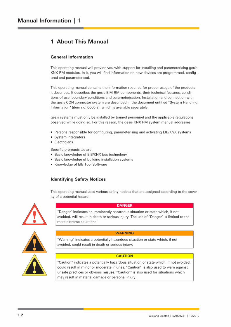
This operating manual uses various safety notices that are assigned according to the sever-ity of a potential hazard:
DANGER
"Danger" indicates an imminently hazardous situation or state which, if not avoided, will result in death or serious injury. The use of "Danger" is limited to the most extreme situations.
WARNING
"Warning" indicates a potentially hazardous situation or state which, if not avoided, could result in death or serious injury.
CAUTION
"Caution" indicates a potentially hazardous situation or state which, if not avoided, could result in minor or moderate injuries. "Caution" is also used to warn against unsafe practices or obvious misuse. "Caution" is also used for situations which may result in material damage or personal injury.
1.3Wieland Electric | BA000231 | 10/2010
1 | Manual Information
NOTICE
"Notice" indicates information that is directly or indirectly related to the safety of personnel or property. It is not directly associated with hazards or hazardous situations.
"Danger" or "Warning" are strictly used for cases which present a risk to life or limb. Damage to property only falls into these categories if there is also a risk of personal injury that corresponds to these levels.
Prescribed Application
WARNING
Electrical installations, activation and maintenance work, as well and configuring • and programming work, must only be performed by qualified electrical techni-cians with relevant accident prevention training, and in compliance with the applicable regulations.Safety precautions and safety devices must comply with the applicable regula-• tions.Compliance with the required regulations is achieved when the devices are • correctly processed in order to create an end product.Damaged products must neither be installed nor put into operation.•
The control system must only be used when in proper working condition, as well as according to its prescribed usage, with due regard given to safety, awareness of any hazards and following the operating manual. Reliable and safe handling assumes proper shipping, storage and installation, as well as careful operation. In particular, safety-related faults must be rectified immediately by a professional.
The control systems are exclusively intended for controlling building equipment. Other applications, or use beyond this scope, is considered to be improper. The manufacturer assumes no responsibility for any damage resulting from usage of this nature.
In order to use the control systems as prescribed, the instructions outlined in this operat-ing manual must be followed for mechanical and electrical installation procedures, as well as for activation and operation of the systems.

1.4 Wieland Electric | BA000231 | 10/2010
Manual Information | 1
Selecting Personnel and Personnel Qualifications
WARNING
Electrical installations, activation and maintenance work, as well and configuring • and programming work, must only be performed by qualified electrical techni-cians with relevant accident prevention training, and in compliance with the applicable regulations.Configuring and programming personnel must be familiar with the safety con-• cepts involved in building installation technology.The operating personnel must be trained in handling the control system and • familiar with the operating instructions.The installation, activation and maintenance personnel must have a training • background which authorises them to carry out work on the control system.
Tests and Repairs
When measurement or testing procedures are being performed on the active device, the specifications and implementation guidelines of the relevant accident prevention regula-tions must be observed. Only suitable tools may be used for this.
Repairs to control components may only be carried out by the manufacturer.
CAUTION
Unauthorised opening and improper intervention or repairs can result in material damage or bodily harm.
In the event of a fault, send devices back to:
Wieland Electric GmbHAbteilung (Department) TQM 3Brennerstrasse 10-14D-96052 Bamberg, Germany
Hazards due to Electrical Energy
The user must ensure that unauthorised and improper intervention is prevented. Personnel must have knowledge of all sources of hazards and measures for activating the equipment. This includes not only data in the gesis "System Handling Information" document (item no. 0060.2) and device packaging inserts, but also the relevant content from this manual.
2.1Wieland Electric | BA000231 | 10/2010
2 | EIB/KNX Bus System
2 The EIB/KNX Bus System
Technology
EIB systems are based on an "installation bus": this refers to the cable which links all the devices that are connected and transfers signals between all the bus nodes.
EIBs are concerned with a remote bus system. A central unit is not requires since each node (bus device) has its own intelligence. The ETS software is used to download all the required parameters to the individual devices via the bus. Different transfer media are avail-able within the EIB.
All Wieland EIB devices use twisted pair (TP) 2-wire bus technology. This uses a sepa-rate cable which is laid at the same time as the standard electrical installation takes place, and supplies the nodes with both power for the electronic components and information (telegrams) such as status messages or switching commands. In larger EIB systems, the lines are electrically isolated from one another using line couplers, which means that each line requires its own power supply. The line couplers ensure that the telegram load on the coupled lines does not become too great. They prevent telegrams that are only required in particular areas from entering other areas, thereby reducing the bus load. The EIB is an event-controlled bus system, which means that telegrams are only created when they are actually needed.
Topology
Each bus connection represents a node, regardless of whether this is concerned with a straightforward button or complex visualisation.
The nodes in each system are divided into sensors (e.g. buttons, temperature sensors), actuators (e.g. switching outputs, shutter outputs) and system devices (e.g. line couplers, voltage supplies).
The smallest unit in the EIB system is a line. A line can link up to 64 nodes. Line couplers enable up to 15 lines to be coupled with a single area. Where complex installations are concerned, it is possible to interconnect a maximum of 15 areas to form a bus world, which then allows for over 13,000 nodes. However, if one bus world is not sufficient, it is possible to couple several bus worlds together.
Addressing
"Addresses" are used for identifying and addressing specific bus nodes, and hence cannot be mixed up. The EIB system uses two address types:
Physical address• During activation, the physical address is assigned to each node. It unambiguously defines each bus node. Since this address is based on the line and area structure, the bus system itself is continually clear, right up to the final extension stage. In addition, the option of physical addressing ensures that the activation engineer has enough leeway to take build-ing structures into account as well. Each device can be addressed in such a way that it can easily be assigned to existing building structures (e.g. "west building, 1st floor, north side").

2.2 Wieland Electric | BA000231 | 10/2010
EIB/KNX Bus System | 2
Group address• The group address is used for communication between the nodes and is independent from the physical address.
Group addresses are assigned to all bus nodes that are to evaluate telegram informa-tion using this group address. For example, the "central off" group address causes all the nodes in this address group to be switched off when the command for this (e.g. pressing a particular switch) is incorporated at a particular position in the bus system. This telegram has no effect on any of the other nodes.
Software
The multivendor ETS software (EIB Tool Software) is the planning, activation and documen-tation software for the EIB. Physical addresses, the group address, building topology, etc. can be defined and changed for not only each device, but also the system as a whole.
The manufacturers provide the specific data for the devices used in the system free of charge, in the form of product databases, and input it into the ETS. This standard software can be used to activate EIB devices, regardless of their manufacturer. This prevents special charges from being incurred, as well as compatibility and parameterisation problems.

3.1Wieland Electric | BA000231 | 10/2010
3 | gesis KNX: System Overview
3 gesis KNX: System Overview
The gesis EIB series of devices arose from combining EIBs with the gesis CON connector system. As a manufacturer of compact connectors for electrical installation, Wieland devel-oped EIB switching devices with pluggable connections which can be connected to gesis connectors. There are currently three different device series available:
• gesis EIB V Has a flat structure, can be directly connected to the 7-pin gesis flat cable and is therefore particularly suitable for low installation areas (such as hollow floors).
• gesis EIB M2 A modular device series. Different extension modules can be added to the basic module, which means that the gesis EIB M2 series can be adapted very well to the different requirements presented by electrical installations.
• gesis KNX RM/RM2 Also a modular device series. The basic and power supply modules are adapted to the building control task at hand using up to four extension modules. The differences between this and the EIB M2 series are the lower installation height (50 mm) and the fact that the parts are prefabricated at the factory (installed in a distribution box, wired and checked). When the distribution box then reaches the site of installation, it only needs to be connected using gesis con-nectors.
All of the gesis devices series are compatible with all EIB devices from other manufacturers and can be used in an extensive range of applications. The gesis EIB V, gesis EIB M2 and gesis KNX RM/RM2 series enable remote installation and place inputs and outputs directly at the consumer. This results in shorter cables, a reduction in thermal loads, smaller cable channels and more space in the distribution box. The pluggable connections and prefabri-cated gesis components also enable faster assembly and help to prevent installation errors.
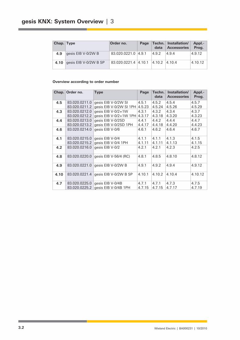
Overview of gesis EIB V Module Descriptions
Overview according to type
Chap. Type Order no. Page Techn. data
Installation/ Accessories
Appl.-Prog.
4.1 gesis EIB V-0/4 gesis EIB V-0/4 1PH
83.020.0215.0 83.020.0215.2
4.1.14.1.11
4.1.14.1.11
4.1.34.1.13
4.1.54.1.15
4.2 gesis EIB V-0/2
83.020.0216.0
4.2.1 4.2.1 4.2.3 4.2.5
4.3 gesis EIB V-0/2+1W gesis EIB V-0/2+1W 1PH
83.020.0212.0 83.020.0212.2
4.3.14.3.17
4.3.24.3.18
4.3.44.3.20
4.3.74.3.23
4.4 gesis EIB V-0/2SD gesis EIB V-0/2SD 1PH
83.020.0213.0 83.020.0213.2
4.4.14.4.17
4.4.24.4.18
4.4.44.4.20
4.4.74.4.23
4.5 gesis EIB V-0/2W SI gesis EIB V-0/2W SI 1PH
83.020.0211.0 83.020.0211.2
4.5.14.5.23
4.5.24.5.24
4.5.44.5.26
4.5.74.5.29
4.6 gesis EIB V-0/6
83.020.0214.0
4.6.1 4.6.2 4.6.4 4.6.7
4.7 gesis EIB V-0/4B gesis EIB V-0/4B 1PH
83.020.0225.0 83.020.0225.2
4.7.14.7.15
4.7.14.7.15
4.7.34.7.17
4.7.54.7.19
4.8 gesis EIB V-56/4 (RC)
83.020.0220.0
4.8.1 4.8.5 4.8.10 4.8.12
3.2 Wieland Electric | BA000231 | 10/2010
gesis KNX: System Overview | 3
Chap. Type Order no. Page Techn. data
Installation/ Accessories
Appl.-Prog.
4.9 gesis EIB V-0/2W B
83.020.0221.0
4.9.1 4.9.2 4.9.4 4.9.12
4.10 gesis EIB V-0/2W B SP
83.020.0221.4
4.10.1 4.10.2 4.10.4 4.10.12
Overview according to order number
Chap. Order no. Type Page Techn. data
Installation/ Accessories
Appl.-Prog.
4.5 83.020.0211.0 83.020.0211.2
gesis EIB V-0/2W SI gesis EIB V-0/2W SI 1PH
4.5.14.5.23
4.5.24.5.24
4.5.44.5.26
4.5.74.5.29
4.3 83.020.0212.0 83.020.0212.2
gesis EIB V-0/2+1W gesis EIB V-0/2+1W 1PH
4.3.14.3.17
4.3.24.3.18
4.3.44.3.20
4.3.74.3.23
4.4 83.020.0213.0 83.020.0213.2
gesis EIB V-0/2SD gesis EIB V-0/2SD 1PH
4.4.14.4.17
4.4.24.4.18
4.4.44.4.20
4.4.74.4.23
4.6 83.020.0214.0
gesis EIB V-0/6
4.6.1 4.6.2 4.6.4 4.6.7
4.1 83.020.0215.0 83.020.0215.2
gesis EIB V-0/4 gesis EIB V-0/4 1PH
4.1.14.1.11
4.1.14.1.11
4.1.34.1.13
4.1.54.1.15
4.2 83.020.0216.0
gesis EIB V-0/2
4.2.1 4.2.1 4.2.3 4.2.5
4.8 83.020.0220.0
gesis EIB V-56/4 (RC)
4.8.1 4.8.5 4.8.10 4.8.12
4.9 83.020.0221.0
gesis EIB V-0/2W B
4.9.1 4.9.2 4.9.4 4.9.12
4.10 83.020.0221.4
gesis EIB V-0/2W B SP
4.10.1 4.10.2 4.10.4 4.10.12
4.7 83.020.0225.0 83.020.0225.2
gesis EIB V-0/4B gesis EIB V-0/4B 1PH
4.7.14.7.15
4.7.14.7.15
4.7.34.7.17
4.7.54.7.19
4.1.1Wieland Electric | BA000231 | 03.2006
4.1 | gesis EIB V-0/4
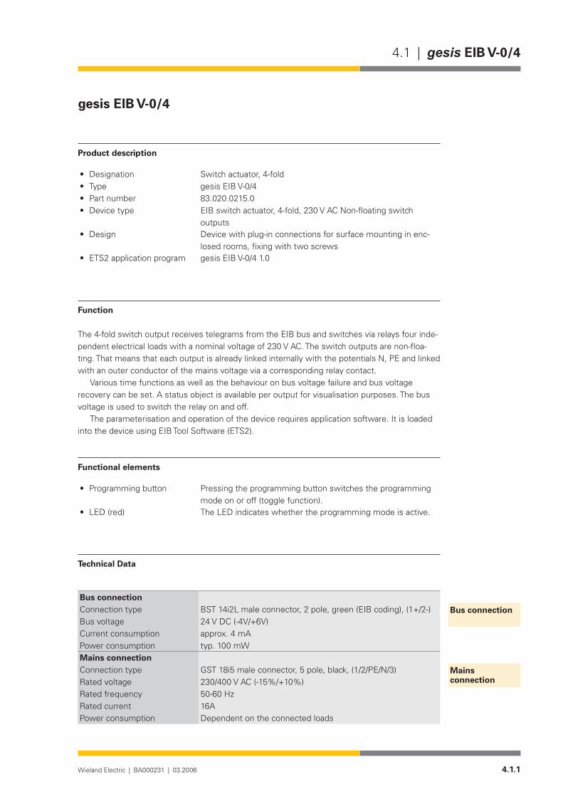
gesis EIB V-0/4
Product description
Designation• Switch actuator, 4-foldType• gesis EIB V-0/4Part number• 83.020.0215.0Device type• EIB switch actuator, 4-fold, 230 V AC Non-floating switch
outputsDesign• Device with plug-in connections for surface mounting in enc-
losed rooms, fixing with two screwsETS2 application program• gesis EIB V-0/4 1.0
Function
The 4-fold switch output receives telegrams from the EIB bus and switches via relays four inde-pendent electrical loads with a nominal voltage of 230 V AC. The switch outputs are non-floa-ting. That means that each output is already linked internally with the potentials N, PE and linked with an outer conductor of the mains voltage via a corresponding relay contact.
Various time functions as well as the behaviour on bus voltage failure and bus voltage recovery can be set. A status object is available per output for visualisation purposes. The bus voltage is used to switch the relay on and off.
The parameterisation and operation of the device requires application software. It is loaded into the device using EIB Tool Software (ETS2).
Functional elements
Programming button• Pressing the programming button switches the programming mode on or off (toggle function).
LED (red)• The LED indicates whether the programming mode is active.
Technical Data
Bus connectionConnection type BST 14i2L male connector, 2 pole, green (EIB coding), (1+/2-)Bus voltage 24 V DC (-4V/+6V)Current consumption approx. 4 mAPower consumption typ. 100 mWMains connectionConnection type GST 18i5 male connector, 5 pole, black, (1/2/PE/N/3)Rated voltage 230/400 V AC (-15%/+10%)Rated frequency 50-60 HzRated current 16APower consumption Dependent on the connected loads
Bus connection
Mains connection
4.1.2 Wieland Electric | BA000231 | 03.2006
gesis EIB V-0/4 | 4.1
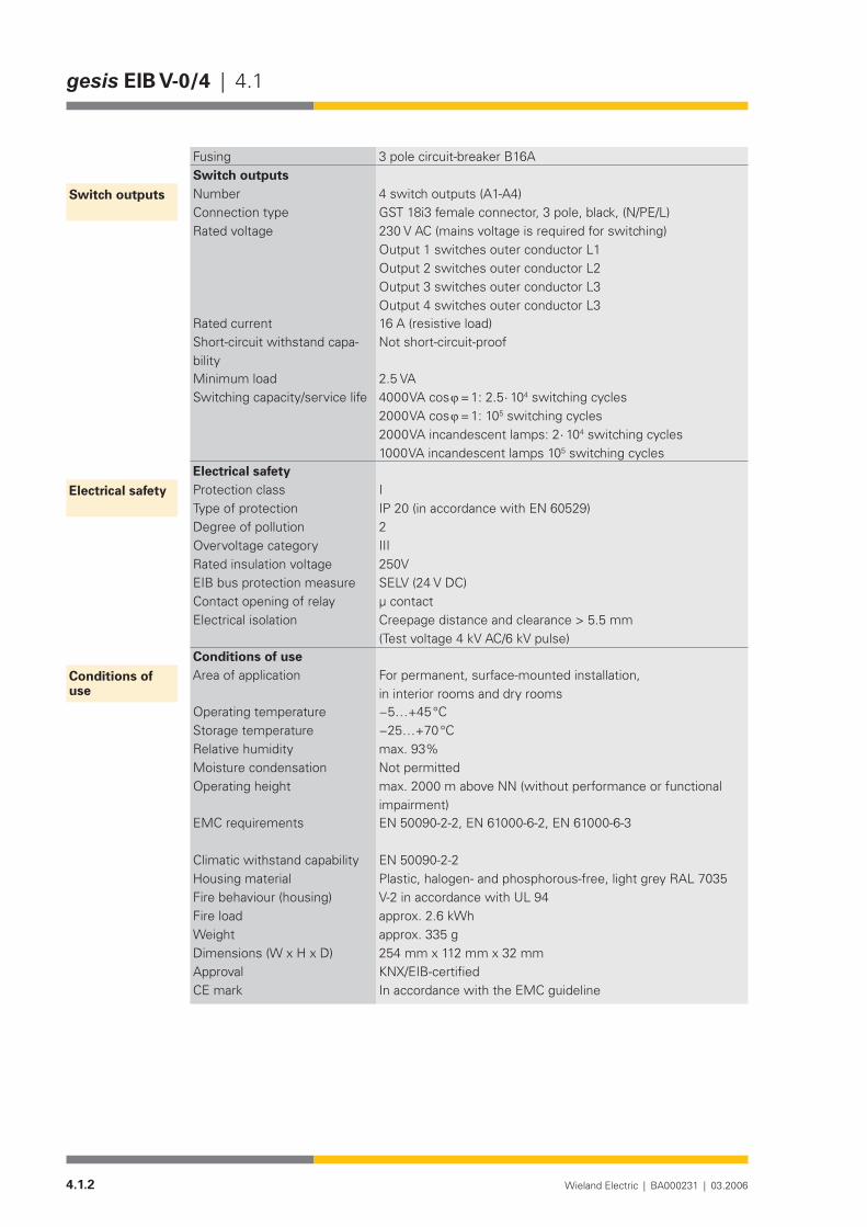
Fusing 3 pole circuit-breaker B16ASwitch outputsNumber 4 switch outputs (A1-A4)Connection type GST 18i3 female connector, 3 pole, black, (N/PE/L)Rated voltage 230 V AC (mains voltage is required for switching)
Output 1 switches outer conductor L1 Output 2 switches outer conductor L2 Output 3 switches outer conductor L3 Output 4 switches outer conductor L3
Rated current 16 A (resistive load)Short-circuit withstand capa-bility
Not short-circuit-proof
Minimum load 2.5 VASwitching capacity/service life 4000 VA cos ϕ = 1: 2.5 ⋅ 104 switching cycles
2000 VA cos ϕ = 1: 105 switching cycles2000 VA incandescent lamps: 2 ⋅ 104 switching cycles1000 VA incandescent lamps 105 switching cycles
Electrical safetyProtection class IType of protection IP 20 (in accordance with EN 60529)Degree of pollution 2Overvoltage category IIIRated insulation voltage 250VEIB bus protection measure SELV (24 V DC)Contact opening of relay µ contactElectrical isolation Creepage distance and clearance > 5.5 mm
(Test voltage 4 kV AC/6 kV pulse)Conditions of useArea of application For permanent, surface-mounted installation,
in interior rooms and dry roomsOperating temperature −5…+45°CStorage temperature −25…+70°CRelative humidity max. 93%Moisture condensation Not permittedOperating height max. 2000 m above NN (without performance or functional
impairment)EMC requirements EN 50090-2-2, EN 61000-6-2, EN 61000-6-3
Climatic withstand capability EN 50090-2-2Housing material Plastic,halogen-andphosphorous-free,lightgreyRAL7035Fire behaviour (housing) V-2 in accordance with UL 94 Fire load approx. 2.6 kWhWeight approx. 335 g Dimensions (W x H x D) 254 mm x 112 mm x 32 mmApproval KNX/EIB-certifiedCE mark In accordance with the EMC guideline
Switch outputs
Electrical safety
Conditions of use
4.1.3Wieland Electric | BA000231 | 03.2006
4.1 | gesis EIB V-0/4
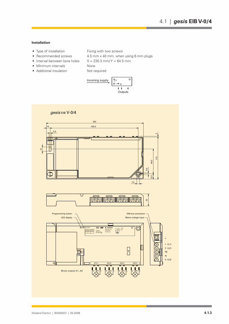
Installation
Type of installation• Fixing with two screwsRecommended screws • 4.5 mm x 40 mm, when using 6 mm plugsInterval between bore holes• X = 230.3 mm/ Y = 64.5 mmMinimum intervals • None Additional insulation • Not required
�
����������������
�������
V-0/4EIB
2
7,5
230,3
12
10
5,5
5,5
64,5
13,7
110
254
gesis
A4/L3A3/L3A2/L2A1/L1
1 (L1)
2 (L2)
PE
N
3 (L3)
-+
Binary outputs A1...A4
Mains voltage input
EIB bus connection
N LPEN LPEN LPEN LPE
Programming button
LED display
32
A1...4PEN
83.020.0215.0
EIB V-0/44 OUTPUTS
16Am
230V~gesis
DEVICELINEAREA
PHYSICAL ADDRESS:
PROGRAM
230/400V50/60Hz; 16A
wielandw
4.1.4 Wieland Electric | BA000231 | 03.2006
gesis EIB V-0/4 | 4.1
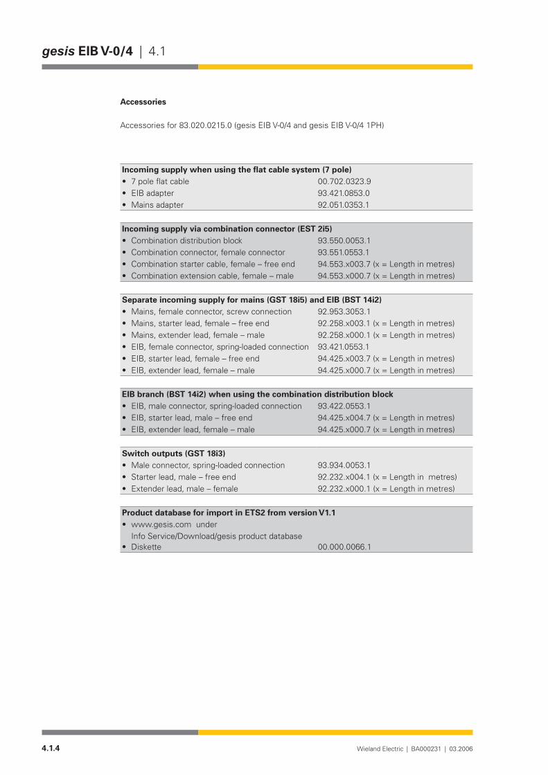
Accessories
Accessories for 83.020.0215.0 (gesis EIB V-0/4 and gesis EIB V-0/4 1PH)
Incoming supply when using the flat cable system (7 pole)7poleflatcable• 00.702.0323.9EIB adapter• 93.421.0853.0Mains adapter• 92.051.0353.1
Incoming supply via combination connector (EST 2i5)Combination distribution block• 93.550.0053.1Combination connector, female connector• 93.551.0553.1Combination starter cable, female – free end• 94.553.x003.7(x=Lengthinmetres)Combination extension cable, female – male• 94.553.x000.7(x=Lengthinmetres)
Separate incoming supply for mains (GST 18i5) and EIB (BST 14i2)Mains, female connector, screw connection• 92.953.3053.1Mains, starter lead, female – free end• 92.258.x003.1 (x = Length in metres)Mains, extender lead, female – male• 92.258.x000.1 (x = Length in metres)EIB, female connector, spring-loaded connection• 93.421.0553.1EIB, starter lead, female – free end• 94.425.x003.7(x=Lengthinmetres)EIB, extender lead, female – male• 94.425.x000.7(x=Lengthinmetres)
EIB branch (BST 14i2) when using the combination distribution blockEIB, male connector, spring-loaded connection• 93.422.0553.1EIB, starter lead, male – free end• 94.425.x004.7(x=Lengthinmetres)EIB, extender lead, female – male• 94.425.x000.7(x=Lengthinmetres)
Switch outputs (GST 18i3)Male connector, spring-loaded connection• 93.934.0053.1Starter lead, male – free end• 92.232.x004.1 (x = Length in metres)Extender lead, male – female• 92.232.x000.1 (x = Length in metres)
Product database for import in ETS2 from version V1.1www.gesis.co• m under Info Service/Download/gesis product databaseDiskette• 00.000.0066.1

4.1.5Wieland Electric | BA000231 | 03.2006
4.1 | gesis EIB V-0/4
Application program
Program name• gesis EIB V-0/4 1.0Program version• 1.0Product assignment• gesis EIB V-0/4, 83.020.0215.0
gesis EIB V-0/4 1PH, 83.020.0215.2Product description• EIB switch actuator, 4-fold switch output 230 V AC
Non-floating outputs, all plug-in connections, surface mounting
ETS2 search path•Manufacturer• Wieland Electric GmbHProduct family• gesis EIB VProduct type• Output
Binary output, 4-fold
The application program controls the four binary outputs of the EIB switch actuator. It is pos-sible to switch electrical loads with these four outputs.
The switching on and off of the corresponding relay is carried out via the bus. Two objects are available per output. One object is used for switching while the other object is used for passive status feedback. The outputs can be configured for different operating modes using the parameters. The delay periods can be set between 130 ms and 152.4 h, whereby one time base and two factors are used. The behaviour on bus voltage failure and bus voltage recovery can be set.
Obj Object name Function Type Flags
0 Switch Output 1 1 bit C W T UReceive
The receipt of a telegram with the useful information ‘0’ switches the output with the set parameters for the OFF delay. On receipt of a ‘1’ telegram, the output is controlled according to the parameter settings for the ON functions.
1 Switch Output 2 1 bit C W T UReceive
The receipt of a telegram with the useful information ‘0’ switches the output with the set parameters for the OFF delay. On receipt of a ‘1’ telegram, the output is controlled according to the parameter settings for the ON functions.
2 Switch Output 3 1 bit C W T UReceive
The receipt of a telegram with the useful information ‘0’ switches the output with the set parameters for the OFF delay. On receipt of a ‘1’ telegram, the output is controlled according to the parameter settings for the ON functions.
General description
Function
Description of the objects
4.1.6 Wieland Electric | BA000231 | 03.2006
gesis EIB V-0/4 | 4.1
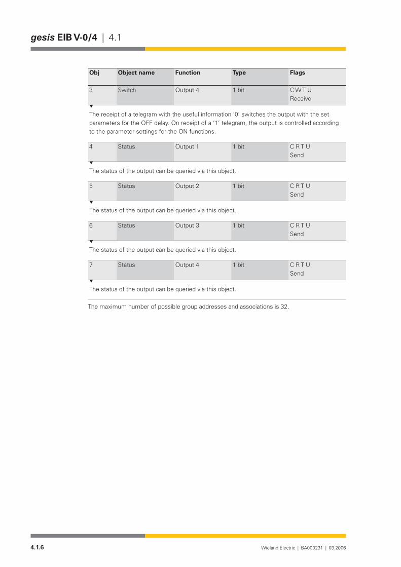
Obj Object name Function Type Flags
3 Switch Output 4 1 bit C W T UReceive
The receipt of a telegram with the useful information ‘0’ switches the output with the set parameters for the OFF delay. On receipt of a ‘1’ telegram, the output is controlled according to the parameter settings for the ON functions.
4 Status Output 1 1 bit C R T USend
The status of the output can be queried via this object.
5 Status Output 2 1 bit C R T USend
The status of the output can be queried via this object.
6 Status Output 3 1 bit C R T USend
The status of the output can be queried via this object.
7 Status Output 4 1 bit C R T USend
The status of the output can be queried via this object.
The maximum number of possible group addresses and associations is 32.

4.1.7Wieland Electric | BA000231 | 03.2006
4.1 | gesis EIB V-0/4
Parameterisation
Default settings are printed in bold type.The following parameters are available separately for each output.
Output 1 / Output 2 / Output 3 / Output 4 are all identical.
Parameters Settings
Behaviour on bus voltage recovery no actionswitch onswitch off
This parameter determines how the bistable relay behaves on bus voltage recovery. If “no ac-tion” is set, the relay remains in the current position. If “switch on” or “switch off” is selected, the corresponding state is created.
Behaviour on bus voltage failure no actionswitch onswitch off
This parameter determines how the bistable relay behaves on bus voltage failure. If “no ac-tion” is set, the relay remains in the current position. If “switch on” or “switch off” is selected, the corresponding state is created.
Operating mode normalON delayOFF delayON and OFF delaytime switch
This operating mode defines whether the output operates normally, with an ON delay, with an OFF delay, with an ON and OFF delay or with a time function (staircase timer function). If “nor-mal” is set, the output operates directly and without a delay. In the other operating modes, the relay is switched according to the parameterised times.
Base for ON delay(only visible in the operating mode “ON delay”)
130 msec260 msec520 msec1.0 sec2.1 sec4.2 sec8.4 sec17sec34 sec1 min 6 sec2 min 12 sec4 min 30 sec9 min18 min35 min1.2 hours
Output 1 Output 2 Output 3 Output 4

4.1.8 Wieland Electric | BA000231 | 03.2006
gesis EIB V-0/4 | 4.1
Parameters Settings
FactorforONdelay(0-127)(only visible in the operating mode “ON de-lay”)
0
Period for ON delay = Base x Factor. The parameters “Base for ON delay” and “Factor for ON delay” define the duration of the ON delay.
Base for OFF delay(only visible in the operating mode “OFF delay”)
130 msec260 msec520 msec1.0 sec2.1 sec4.2 sec8.4 sec17sec34 sec1 min 6 sec2 min 12 sec4 min 30 sec9 min18 min35 min1.2 hours
FactorforOFFdelay(0-127)(only visible in the operating modes “OFF delay”)
0
Period for OFF delay = Base x Factor. The parameters “Base for OFF delay” and “Factor for OFF delay” define the duration of the OFF delay.
Base for delay(only visible in the operating mode “ON and OFF delay”)
130 msec260 msec520 msec1.0 sec2.1 sec4.2 sec8.4 sec17sec34 sec1 min 6 sec2 min 12 sec4 min 30 sec9 min18 min35 min1.2 hours
FactorforONdelay(0-127)(only visible in the operating mode “ON and OFF delay”)
0

4.1.9Wieland Electric | BA000231 | 03.2006
4.1 | gesis EIB V-0/4
Parameters Settings
FactorforOFFdelay(0-127)(only visible in the operating mode “ON and OFF delay”)
0
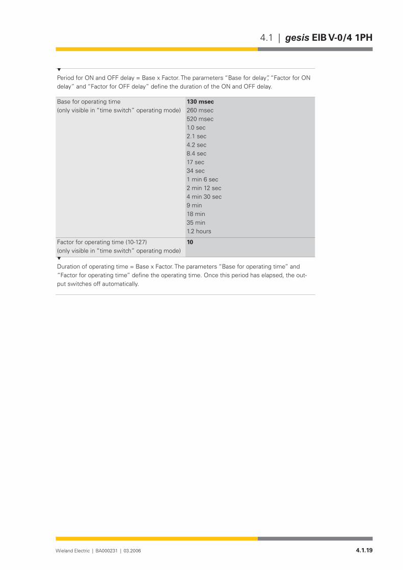
Period for ON and OFF delay = Base x Factor. The parameters “Base for delay”, “Factor for ON delay” and “Factor for OFF delay” define the duration of the ON and OFF delay.
Base for operating time(only visible in “time switch” operating mode)
130 msec260 msec520 msec1.0 sec2.1 sec4.2 sec8.4 sec17sec34 sec1 min 6 sec2 min 12 sec4 min 30 sec9 min18 min35 min1.2 hours
Factorforoperatingtime(10-127)(only visible in “time switch” operating mode)
10
Duration of operating time = Base x Factor. The parameters “Base for operating time” and “Factor for operating time” define the operating time. Once this period has elapsed, the out-put switches off automatically.

4.1.10 Wieland Electric | BA000231 | 03.2006
gesis EIB V-0/4 | 4.1

4.1.11Wieland Electric | BA000231 | 03.2006
4.1 | gesis EIB V-0/4 1PH
gesis EIB V-0/4 1PH
Product description
Designation• Switch actuator, 4-fold, 1-phaseType• gesis EIB V-0/4 1PHPart number• 83.020.0215.2Device type• EIB switch actuator, 4-fold, 230 V AC
Non-floating switch outputsDesign• Device with plug-in connections for surface mounting in enc-
losed rooms, fixing with two screwsETS2 application program• gesis EIB V-0/4 1.0
Function
The 4-fold switch output receives telegrams from the EIB bus and switches via relays four inde-pendent electrical loads with a nominal voltage of 230 V AC. The switch outputs are non-floa-ting. That means that each output is already linked internally with the potentials N, PE and linked with an outer conductor of the mains voltage via a corresponding relay contact.
Various time functions as well as the behaviour on bus voltage failure and bus voltage recovery can be set. A status object is available per output for visualisation purposes. The bus voltage is used to switch the relay on and off.
The parameterisation and operation of the device requires application software. It is loaded into the device using EIB Tool Software (ETS2).
Functional elements
Programming button• Pressing the programming button switches the programming mode on or off (toggle function).
LED (red)• The LED indicates whether the programming mode is active.
Technical Data
Bus connectionConnection type BST 14i2L male connector, 2 pole, green (EIB coding), (1+/2-)Bus voltage 24 V DC (-4V/+6V)Current consumption approx. 4 mAPower consumption typ. 100 mWMains connectionConnection type GST 18i5 male connector, 5 pole, black, (1/2/PE/N/3)Rated voltage 230 V AC (-15%/+10%)Rated frequency 50-60HzRated current 16APower consumption Dependent on the connected loads
Bus connection
Mains connection

4.1.12 Wieland Electric | BA000231 | 03.2006
gesis EIB V-0/4 1PH | 4.1
Fusing Circuit-breaker B16ASwitch outputsNumber 4 switch outputs (A1-A4)Connection type GST 18i3 female connector, 3 pole, black, (N/PE/L)Rated voltage 230 V AC (mains voltage is required for switching) A1 – A4
linked to connection 2Rated current 16 A (resistive load)Short-circuit/ withstand capability
Not short-circuit-proof
Minimum load 2.5 VASwitching capacity/service life 4000VA cos ϕ = 1: 2,5 ⋅ 104 switching cycles
2000VA cos ϕ = 1: 105 switching cycles 2000VA incandescent lamps: 2 ⋅ 104 switching cycles 1000VA incandescent lamps: 105 switching cycles
Electrical safetyProtection class IType of protection IP 20 (in accordance with EN 60529)EIBA Usage Class B (internal + external)Degree of pollution 2Overvoltage category IIIRated insulation voltage 250 VEIB bus protection measure SELV (24 V DC)Contact opening of relay µ contactElectrical isolation Creepage distance and clearance > 5.5 mm
(Test voltage 4 kV AC/6 kV pulse)Conditions of useOperating conditionsArea of application For permanent, surface-mounted installation, in interior rooms
and dry roomsOperating temperature -5...+45°CStorage temperature -25...+70°CRelative humidity max. 93%Moisture condensation Not permittedOperating height max. 2000 m above NNEMC requirements EN 50090-2-2, EN 61000-6-2, EN 61000-6-3 Climatic withstand capability EN 50090-2-2Housing material Plastic,halogen-andphosphorous-free,lightgreyRAL7035Fire behaviour (housing) V-2 in accordance with UL 94 (consists of glow-wire test at
960°CinaccordancewithIEC695-2-1)Fire load approx. 2.6 kWhWeight approx. 335 gDimensions (W x H x D) 254 mm x 112 mm x 32 mmApproval KNX/EIB-certifiedCE mark In accordance with the EMC guideline (residential and functio-
nal buildings), low voltage guideline
Switch outputs
Electrical safety
Conditions of use
4.1.13Wieland Electric | BA000231 | 03.2006
4.1 | gesis EIB V-0/4 1PH
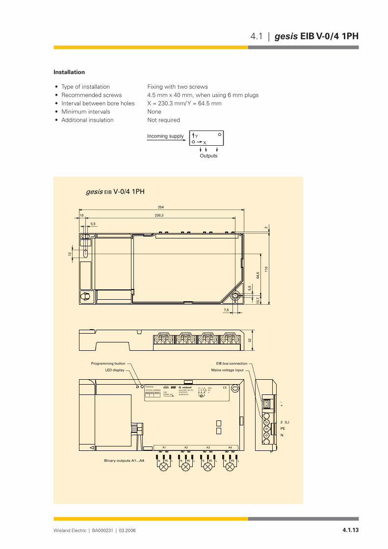
Installation
Type of installation• Fixing with two screwsRecommended screws • 4.5 mm x 40 mm, when using 6 mm plugsInterval between bore holes• X = 230.3 mm/ Y = 64.5 mmMinimum intervals • None Additional insulation • Not required
�
����������������
�������
254
110
13,7
64,5
5,5
5,5
10
12
230,3
7,5
2
EIB V-0/4 1PHgesis
A1 A2 A3 A4
2 (L)
PE
N
-+
PE LN PE LN PE LN PE LNBinary outputs A1...A4
32
A1...4PEN
83.020.0215.2
EIB V-0/4 1PH4 OUTPUTS
16Am
230V~wielandw
gesisDEVICELINEAREA
PHYSICAL ADDRESS:
PROGRAM
230V50/60Hz; 16A
Mains voltage input
EIB bus connectionProgramming button
LED display

4.1.14 Wieland Electric | BA000231 | 03.2006
gesis EIB V-0/4 1PH | 4.1
Accessories
Accessories for 83.020.0215.0 (gesis EIB V-0/4 and gesis EIB V-0/4 1PH)
Incoming supply when using the flat cable system (7 pole)7poleflatcable• 00.702.0323.9EIB adapter• 93.421.0853.0Mains adapter• 92.051.0353.1
Incoming supply via combination connector (EST 2i5)Combination distribution block• 93.550.0053.1Combination connector, female connector• 93.551.0553.1Combination starter cable, female – free end• 94.553.x003.7(x=Lengthinmetres)Combination extension cable, female – male• 94.553.x000.7(x=Lengthinmetres)
Separate incoming supply for mains (GST 18i5) and EIB (BST 14i2)Mains, female connector, screw connection• 92.953.3053.1Mains, starter lead, female – free end• 92.258.x003.1 (x = Length in metres)Mains, extender lead, female – male• 92.258.x000.1 (x = Length in metres)EIB, female connector, spring-loaded connection• 93.421.0553.1EIB, starter lead, female – free end• 94.425.x003.7(x=Lengthinmetres)EIB, extender lead, female – male• 94.425.x000.7(x=Lengthinmetres)
EIB branch (BST 14i2) when using the combination distribution blockEIB, male connector, spring-loaded connection• 93.422.0553.1EIB, starter lead, male – free end• 94.425.x004.7(x=Lengthinmetres)EIB, extender lead, female – male• 94.425.x000.7(x=Lengthinmetres)
Switch outputs (GST 18i3)Male connector, spring-loaded connection• 92.934.0053.1Starter lead, male – free end• 92.232.x004.1 (x = Length in metres)Extender lead, male – female• 92.232.x000.1 (x = Length in metres)
SoftwareProduct database for import in ETS2 •from version V1.1
www.gesis.com (see under „Info Ser-vice/Download/gesis product database“)
Diskette• 00.000.0066.1

4.1.15Wieland Electric | BA000231 | 03.2006
4.1 | gesis EIB V-0/4 1PH
Application program
• Program name gesis EIB V-0/4 1.0Program version• 1.0Product assignment• gesis EIB V-0/4, 83.020.0215.0,
gesis EIB V-0/4 1PH, 83.020.0215.2Product description• EIB switch actuator, 4-fold switch output 230 V AC Non-floating
outputs, all plug-in connections, surface mountingETS2 search path•Manufacturer• Wieland Electric GmbHProduct family• gesis EIB VProduct type• Output Binary output, 4-fold
The application program controls the four binary outputs of the EIB switch actuator. It is pos-sible to switch electrical loads with these four outputs.
The switching on and off of the corresponding relay is carried out via the bus. Two objects are available per output. One object is used for switching while the other object is used for passive status feedback. The outputs can be configured for different operating modes using the parameters. The delay periods can be set between 130 ms and 152.4 h, whereby one time base and two factors are used. The behaviour on bus voltage failure and bus voltage recovery can be set.
Obj Function Object name Type Flags
0 Switch Output 1 1 bit C W T UReceive
The receipt of a telegram with the useful information ‘0’ switches the output with the set parameters for the OFF delay. On receipt of a ‘1’ telegram, the output is controlled according to the parameter settings for the ON functions.
1 Switch Output 2 1 bit C W T U Receive
The receipt of a telegram with the useful information ‘0’ switches the output with the set parameters for the OFF delay. On receipt of a ‘1’ telegram, the output is controlled according to the parameter settings for the ON functions.
2 Switch Output 3 1 bit C W T UReceive
The receipt of a telegram with the useful information ‘0’ switches the output with the set parameters for the OFF delay. On receipt of a ‘1’ telegram, the output is controlled according to the parameter settings for the ON functions.
General description
Function
Description of the objects

4.1.16 Wieland Electric | BA000231 | 03.2006
gesis EIB V-0/4 1PH | 4.1
Obj Function Object name Type Flags
3 Switch Output 4 1 bit C W T UReceive
The receipt of a telegram with the useful information ‘0’ switches the output with the set parameters for the OFF delay. On receipt of a ‘1’ telegram, the output is controlled according to the parameter settings for the ON functions.
4 Status Output 1 1 bit C R T USend
The status of the output can be queried via this object.
5 Status Output 2 1 bit C R T USend
The status of the output can be queried via this object.
6 Status Output 3 1 bit C R T USend
The status of the output can be queried via this object.
7 Status Output 4 1 bit C R T USend
The status of the output can be queried via this object.
The maximum number of possible group addresses and associations is 32.

4.1.17Wieland Electric | BA000231 | 03.2006
4.1 | gesis EIB V-0/4 1PH
Parameterisation
Default settings are printed in bold type.The following parameters are available separately for each output.
Output 1 / Output 2 / Output 3 / Output 4 are all identical.
Parameters Settings
Behaviour on bus voltage recovery no actionswitch onswitch off
This parameter determines how the bistable relay behaves on bus voltage recovery. If “no ac-tion” is set, the relay remains in the current position. If “switch on” or “switch off” is selected, the corresponding state is created.
Behaviour on bus voltage failure no actionswitch onswitch off
This parameter determines how the bistable relay behaves on bus voltage failure. If “no ac-tion” is set, the relay remains in the current position. If “switch on” or “switch off” is selected, the corresponding state is created.
Operating mode normalON delayOFF delayON and OFF delaytime switch
This operating mode defines whether the output operates normally, with an ON delay, with an OFF delay, with an ON and OFF delay or with a time function (staircase timer function). If “nor-mal” is set, the output operates directly and without a delay. In the other operating modes, the relay is switched according to the parameterised times.
Base for ON delay(only visible in the operating mode “ON de-lay”)
130 msec260 msec520 msec1.0 sec2.1 sec4.2 sec8.4 sec17sec34 sec1 min 6 sec2 min 12 sec4 min 30 sec9 min18 min35 min1.2 hours
Output 1 Output 2 Output 3 Output 4

4.1.18 Wieland Electric | BA000231 | 03.2006
gesis EIB V-0/4 1PH | 4.1
FactorforONdelay(0-127)(only visible in the operating mode “ON de-lay”)
0
Period for ON delay = Base x Factor. The parameters “Base for ON delay” and “Factor for ON delay” define the duration of the ON delay.
Base for OFF delay(only visible in the operating mode “OFF delay”)
130 msec260 msec520 msec1.0 sec2.1 sec4.2 sec8.4 sec17sec34 sec1 min 6 sec2 min 12 sec4 min 30 sec9 min18 min35 min1.2 hours
FactorforOFFdelay(0-127)(only visible in the operating modes “OFF delay”)
0
Period for OFF delay = Base x Factor. The parameters “Base for OFF delay” and “Factor for OFF delay” define the duration of the OFF delay.
Base for delay(only visible in the operating mode “ON and OFF delay”)
130 msec260 msec520 msec1.0 sec2.1 sec4.2 sec8.4 sec17sec34 sec1 min 6 sec2 min 12 sec4 min 30 sec9 min18 min35 min1.2 hours
FactorforONdelay(0-127)(only visible in the operating mode “ON and OFF delay”)
0
FactorforOFFdelay(0-127)(only visible in the operating mode “ON and OFF delay”)
0
4.1.19Wieland Electric | BA000231 | 03.2006
4.1 | gesis EIB V-0/4 1PH
Period for ON and OFF delay = Base x Factor. The parameters “Base for delay”, “Factor for ON delay” and “Factor for OFF delay” define the duration of the ON and OFF delay.
Base for operating time(only visible in “time switch” operating mode)
130 msec260 msec520 msec1.0 sec2.1 sec4.2 sec8.4 sec17sec34 sec1 min 6 sec2 min 12 sec4 min 30 sec9 min18 min35 min1.2 hours
Factorforoperatingtime(10-127)(only visible in “time switch” operating mode)
10
Duration of operating time = Base x Factor. The parameters “Base for operating time” and “Factor for operating time” define the operating time. Once this period has elapsed, the out-put switches off automatically.

4.1.20 Wieland Electric | BA000231 | 03.2006
gesis EIB V-0/4 1PH | 4.1
4.2.1Wieland Electric | BA000231 | 03.2006
4.2 | gesis EIB V-0/2 W
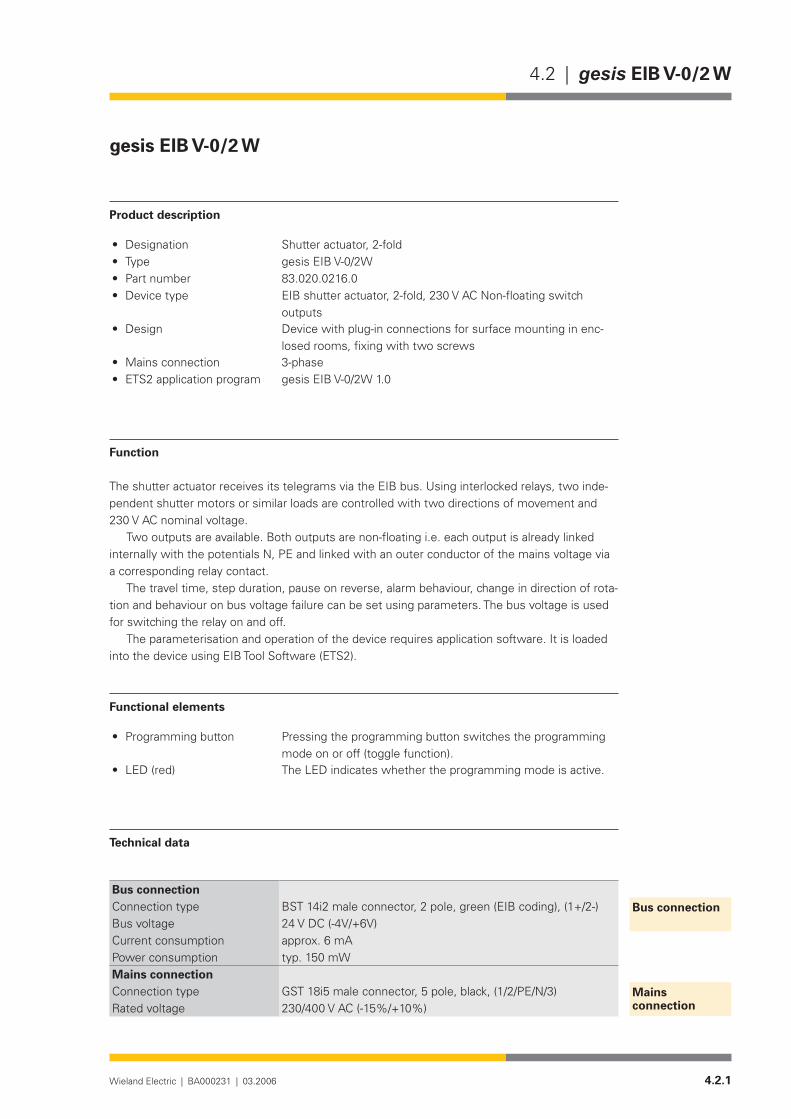
gesis EIB V-0/2 W
Product description
Designation• Shutter actuator, 2-foldType• gesis EIB V-0/2WPart number• 83.020.0216.0Device type• EIB shutter actuator, 2-fold, 230 V AC Non-floating switch
outputsDesign• Device with plug-in connections for surface mounting in enc-
losed rooms, fixing with two screwsMains connection • 3-phase ETS2 application program• gesis EIB V-0/2W 1.0
Function
The shutter actuator receives its telegrams via the EIB bus. Using interlocked relays, two inde-pendent shutter motors or similar loads are controlled with two directions of movement and 230 V AC nominal voltage.
Two outputs are available. Both outputs are non-floating i.e. each output is already linked internally with the potentials N, PE and linked with an outer conductor of the mains voltage via a corresponding relay contact.
The travel time, step duration, pause on reverse, alarm behaviour, change in direction of rota-tion and behaviour on bus voltage failure can be set using parameters. The bus voltage is used for switching the relay on and off.
The parameterisation and operation of the device requires application software. It is loaded into the device using EIB Tool Software (ETS2).
Functional elements
Programming button• Pressing the programming button switches the programming mode on or off (toggle function).
LED (red)• The LED indicates whether the programming mode is active.
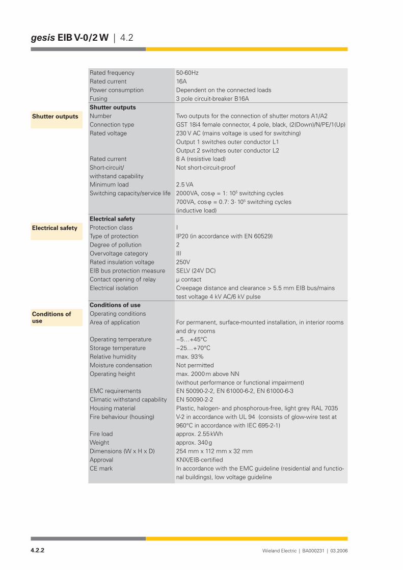
Technical data
Bus connectionConnection type BST 14i2 male connector, 2 pole, green (EIB coding), (1+/2-)Bus voltage 24 V DC (-4V/+6V)Current consumption approx. 6 mAPower consumption typ. 150 mWMains connectionConnection type GST 18i5 male connector, 5 pole, black, (1/2/PE/N/3)Rated voltage 230/400 V AC (-15%/+10%)
Bus connection
Mains connection
4.2.2 Wieland Electric | BA000231 | 03.2006
gesis EIB V-0/2 W | 4.2
Rated frequency 50-60HzRated current 16APower consumption Dependent on the connected loadsFusing 3 pole circuit-breaker B16AShutter outputsNumber Two outputs for the connection of shutter motors A1/A2Connection type GST 18i4 female connector, 4 pole, black, (2(Down)/N/PE/1(Up)Rated voltage 230 V AC (mains voltage is used for switching)
Output 1 switches outer conductor L1 Output 2 switches outer conductor L2
Rated current 8 A (resistive load)Short-circuit/ withstand capability
Not short-circuit-proof
Minimum load 2.5 VASwitching capacity/service life 2000 VA, cos ϕ = 1: 105 switching cycles
700VA,cosϕ=0.7:3⋅ 105 switching cycles (inductive load)
Electrical safetyProtection class IType of protection IP20 (in accordance with EN 60529)Degree of pollution 2Overvoltage category IIIRated insulation voltage 250VEIB bus protection measure SELV (24V DC)Contact opening of relay µ contactElectrical isolation Creepage distance and clearance > 5.5 mm EIB bus/mains
test voltage 4 kV AC/6 kV pulseConditions of useOperating conditionsArea of application For permanent, surface-mounted installation, in interior rooms
and dry roomsOperating temperature −5…+45°CStorage temperature −25…+70°CRelative humidity max. 93%Moisture condensation Not permittedOperating height max. 2000 m above NN
(without performance or functional impairment)EMC requirements EN 50090-2-2, EN 61000-6-2, EN 61000-6-3 Climatic withstand capability EN 50090-2-2Housing material Plastic,halogen-andphosphorous-free,lightgreyRAL7035Fire behaviour (housing) V-2 in accordance with UL 94 (consists of glow-wire test at
960°CinaccordancewithIEC695-2-1)Fire load approx. 2.55 kWhWeight approx. 340 gDimensions (W x H x D) 254 mm x 112 mm x 32 mmApproval KNX/EIB-certifiedCE mark In accordance with the EMC guideline (residential and functio-
nal buildings), low voltage guideline
Shutter outputs
Electrical safety
Conditions of use
4.2.3Wieland Electric | BA000231 | 03.2006
4.2 | gesis EIB V-0/2 W
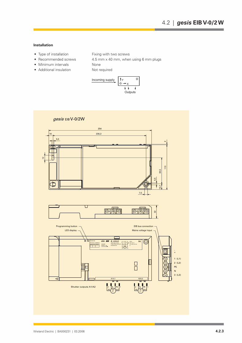
Installation
Type of installation• Fixing with two screwsRecommended screws • 4.5 mm x 40 mm, when using 6 mm plugsMinimum intervals• NoneAdditional insulation • Not required
�
����������������
�������
V-0/2WEIB
2
7,5
230,3
12
10
5,5
5,5
64,5
13,7
110
254
gesis
A2/L2A1/L1
2 PEN 1 1N PE2
1~M AufAb Ab Auf
1 (L1)
2 (L2)
PE
N
3 (L3)
-+
Shutter outputs A1/A2
32
1~M
DEVICELINEAREA
PHYSICAL ADDRESS:
PROGRAM
230/400V50/60Hz; 16A 83.020.0216.0
EIB V-0/2W2 SHUTTER OUTPUTSgesis
wielandw 230V~
m
8A cos =13A cos =0,4 ind.
N PEA1/A2
M1~ AufAb
Mains voltage input
EIB bus connectionProgramming button
LED display

4.2.4 Wieland Electric | BA000231 | 03.2006
gesis EIB V-0/2 W | 4.2
Accessories
Accessories for 83.020.0211.x (gesis EIB V-0/2W and gesis EIB V-0/2W 1 PH)
Incoming supply when using the flat cable system (7 pole)7poleflatcable• 00.702.0323.9EIB adapter• 93.421.0853.0Mains adapter• 92.051.0353.1
Incoming supply via combination connector (EST 2i5)Combination distribution block• 93.550.0053.1Combination connector, female connector• 93.551.0553.1Combination starter cable, female – free end• 94.553.x003.7x=LengthinmetresCombination extension cable, female – male• 94.553.x000.7x=Lengthinmetres
Separate incoming supply for mains (GST 18i5) and EIB (BST 14i2)Mains, female connector, screw connection• 92.953.3053.1Mains, starter lead, female – free end• 92.258.x003.1 x = Length in metresMains, extender lead, female – male• 92.258.x000.1 x = Length in metresEIB, female connector, spring-loaded connection• 93.421.0553.1EIB, starter lead, female – free end• 94.425.x003.7x=LengthinmetresEIB, extender lead, female – male• 94.425.x000.7x=Lengthinmetres
EIB branch (BST 14i2) when using the combination distribution blockEIB, male connector, spring-loaded connection• 93.422.0553.1EIB, starter lead, male – free end• 94.425.x004.7x=LengthinmetresEIB, extender lead, female – male• 94.425.x000.7x=Lengthinmetres
Shutter outputs (GST 18i4)Male connector, spring-loaded connection• 92.944.1053.1Starter lead, male – free end• 92.207.x004.1x=LengthinmetresExtender lead, male – female• 92.207.x000.1x=LengthinmetresProduct database for import in ETS2 •from version V1.1
www.gesis.com (see under Info Service/Download/gesis product database
Diskette• 00.000.0066.1
SoftwareProduct database for import in ETS2 •from version V1.1
www.gesis.com (see under Info Service/Download/gesis product database
Diskette• 00.000.0066.1
4.2.5Wieland Electric | BA000231 | 03.2006
4.2 | gesis EIB V-0/2 W
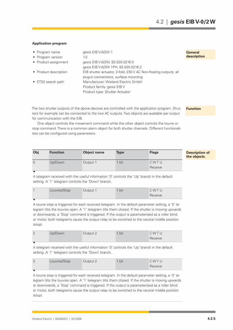
Application program
• Program name gesis EIB V-0/2W 1Program version• 1.0Product assignment• gesis EIB V-0/2W, 83.020.0216.0
gesis EIB V-0/2W 1PH, 83.020.0216.2Product description• EIB shutter actuator, 2-fold, 230 V AC Non-floating outputs, all
plug-in connections, surface mountingETS2 search path• Manufacturer: Wieland Electric GmbH
Product family: gesis EIB V Product type: Shutter Actuator
The two shutter outputs of the above devices are controlled with the application program. Shut-ters for example can be connected to the two AC outputs. Two objects are available per output for communication with the EIB.
One object controls the movement command while the other object controls the louvre or stop command. There is a common alarm object for both shutter channels. Different functionali-ties can be configured using parameters.
Obj Function Object name Type Flags
0 Up/Down Output 1 1 bit C W T UReceive
A telegram received with the useful information ‘0’ controls the ‘Up’ branch in the default setting. A ‘1’ telegram controls the ‘Down’ branch.
1 Louvres/Stop Output 1 1 bit C W T UReceive
A louvre step is triggered for each received telegram. In the default parameter setting, a ‘0’ te-legram tilts the louvres open. A ‘1’ telegram tilts them closed. If the shutter is moving upwards or downwards, a ‘Stop’ command is triggered. If the output is parameterised as a roller blind or motor, both telegrams cause the output relay to be switched to the neutral middle position (stop).
2 Up/Down Output 2 1 bit C W T UReceive
A telegram received with the useful information ‘0’ controls the ‘Up’ branch in the default setting. A ‘1’ telegram controls the ‘Down’ branch.
3 Louvres/Stop Output 2 1 bit C W T UReceive
A louvre step is triggered for each received telegram. In the default parameter setting, a ‘0’ te-legram tilts the louvres open. A ‘1’ telegram tilts them closed. If the shutter is moving upwards or downwards, a ‘Stop’ command is triggered. If the output is parameterised as a roller blind or motor, both telegrams cause the output relay to be switched to the neutral middle position (stop).
General description
Function
Description of the objects

4.2.6 Wieland Electric | BA000231 | 03.2006
gesis EIB V-0/2 W | 4.2
4 Safety/Alarm Output 1 1 bit C W T U
The safety object influences both shutter objects. The receipt of a ‘1’ telegram triggers the actions set in the parameters in the event of an alarm. It also disables the actuator channel which evaluates the alarm for further operation. A ‘0’ telegram cancels this alarm and enables operation again. If there is no alarm present, the ‘0’ telegram must be received within the set monitoring period.
The maximum number of possible group addresses and associations is 21.
4.2.7Wieland Electric | BA000231 | 03.2006
4.2 | gesis EIB V-0/2 W
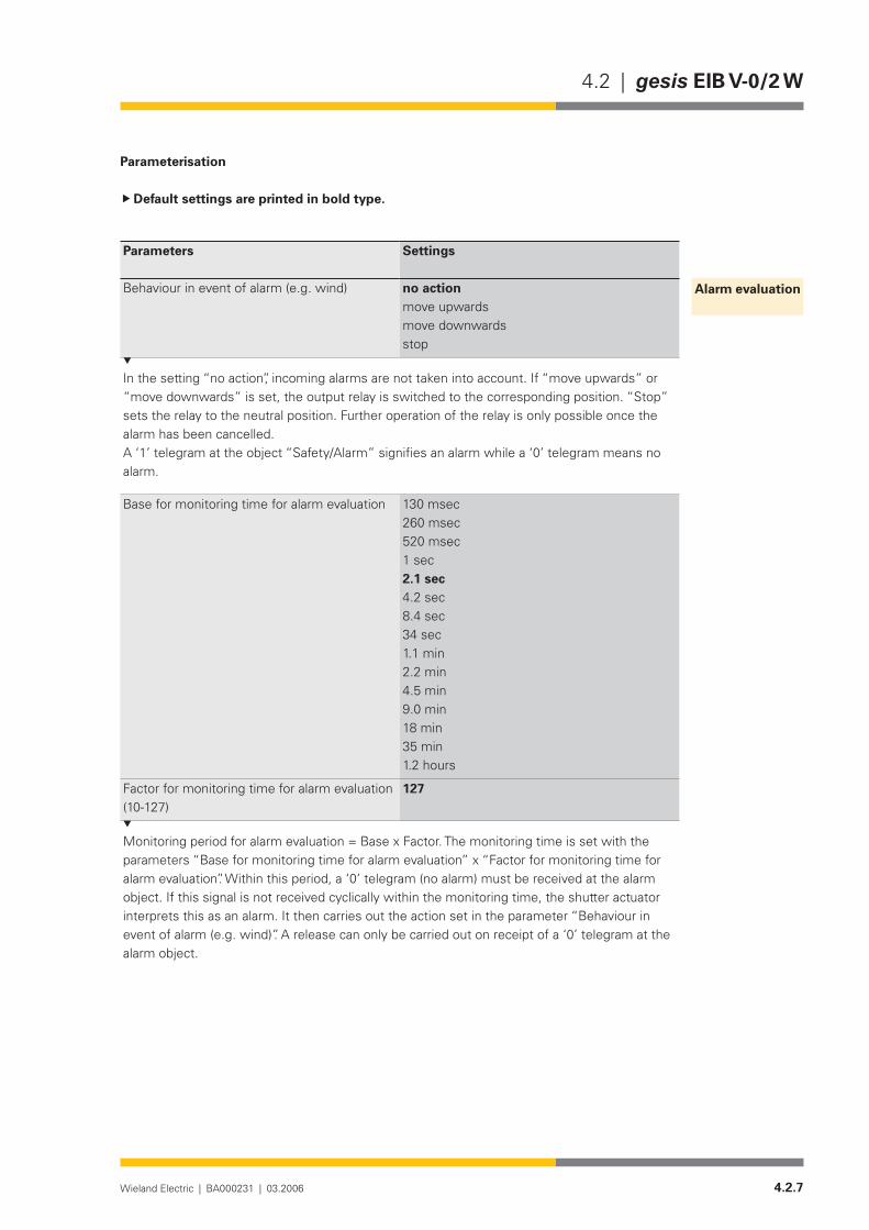
Parameterisation
Default settings are printed in bold type.
Parameters Settings
Behaviour in event of alarm (e.g. wind) no actionmove upwardsmove downwardsstop
In the setting “no action”, incoming alarms are not taken into account. If “move upwards” or “move downwards” is set, the output relay is switched to the corresponding position. “Stop” sets the relay to the neutral position. Further operation of the relay is only possible once the alarm has been cancelled.A ‘1’ telegram at the object “Safety/Alarm” signifies an alarm while a ‘0’ telegram means no alarm.
Base for monitoring time for alarm evaluation 130 msec260 msec520 msec1 sec2.1 sec4.2 sec8.4 sec34 sec1.1 min2.2 min4.5 min9.0 min18 min35 min1.2 hours
Factor for monitoring time for alarm evaluation (10-127)
127
Monitoring period for alarm evaluation = Base x Factor. The monitoring time is set with the parameters “Base for monitoring time for alarm evaluation” x “Factor for monitoring time for alarm evaluation”. Within this period, a ‘0’ telegram (no alarm) must be received at the alarm object. If this signal is not received cyclically within the monitoring time, the shutter actuator interprets this as an alarm. It then carries out the action set in the parameter “Behaviour in event of alarm (e.g. wind)”. A release can only be carried out on receipt of a ‘0’ telegram at the alarm object.
Alarm evaluation

4.2.8 Wieland Electric | BA000231 | 03.2006
gesis EIB V-0/2 W | 4.2
Parameters Settings
Operating mode shutter actuator (with travel time)motor control (continuous operation)
This parameter determines whether the relay (output) is automatically switched to a neutral position once the travel time has elapsed (“shutter actuator (with travel time)”) or whether the neutral position can only be reached with a stop command (“motor control (continuous operati-on)”). The parameter applies to both channels simultaneously.
Base for travel time(only visible in the operating mode “shutter actuator (with travel time)”)
0.5 msec8 msec130 msec2.1 sec33 sec
Factor for travel time (10-255)(only visible in the operating mode “shutter actuator (with travel time)”)
48
When the period calculated from the “Base for travel time” x “Factor for travel time” has elapsed, the relay reverts to the neutral position.
Louvre adjustment (shutter/roller blind)(only visible in the operating mode “shutter actuator (with travel time)”)
active (e.g. shutter)inactive (e.g. roller blind)
In the setting “active”, a command at the object “Louvres/Stop” is interpreted as a louvre step or stop. In the setting “inactive”, this command is interpreted as a pure stop command.
Base for louvre adjustment/pause on reverse(only visible in the operating mode “shutter actuator (with travel time)”)
0.5 msec8 msec130 msec2.1 sec33 sec
Factor for louvre adjustment (10-255)(only visible in the operating mode “shutter actuator (with travel time)” and “Louvre adjust-ment (shutter/roller blind) = active”)
24
The time calculated from the parameters “Base for louvre adjustment/pause on reverse” and “Factor for louvre adjustment” indicates how long the relay must remain in the UP or DOWN position after a louvre step until it returns to the neutral middle position.
Factor for pause on reverse (10-255) 60
The time calculated from the parameters “Base for louvre adjustment/pause on reverse” and “Factor for pause on reverse” indicates how long a relay remains in the neutral middle position after a direct change in direction. This applies to both operating modes “shutter actuator (with travel time)” and “motor control (continuous operation)”.
Outputs 1 and 2

4.2.9Wieland Electric | BA000231 | 03.2006
4.2 | gesis EIB V-0/2W
Parameters Settings
Behaviour on bus voltage failure no actionmove upwardsmove downwardsstop
This parameter defines how the relay switches on bus voltage failure. The setting “no action” means that the relay maintains the position which it held on voltage failure. This applies to both operating modes “shutter actuator (with travel time)” and “motor control (continuous operati-on)”.
Direction of rotation normalinverted
If the direction of rotation has been mixed up when installing the motor, the output can be inverted with this parameter.

4.2.10 Wieland Electric | BA000231 | 03.2006
gesis EIB V-0/2 W | 4.2

4.3.1Wieland Electric | BA000231 | 03.2006
4.3 | gesis EIB V-0/2+1W
gesis EIB V-0/2+1W
Product description
Designation• Combi actuator, 3-foldType• gesis EIB V-0/2+1WPart number• 83.020.0212.0Device type• EIB switch actuator, 3-fold, 230 V AC Non-floating switch out-
puts (2 binary outputs/1 shutter outputs)Design• Device with plug-in connections for surface mounting in enc-
losed rooms, fixing with two screwsETS2 application program• gesis EIB V-0/2+1W 1.0
Function
The combi actuator receives telegrams via the EIB bus and switches two independent electrical loads and a shutter motor via relays or similar loads with 230 V AC nominal voltage. The switch outputs are non-floating. That means that each output is already linked internally with the po-tentials N, PE and linked with an outer conductor of the mains voltage via a corresponding relay contact.
Various time functions, logic operations, contact type of the relay, status object, behaviour on bus voltage failure and bus voltage recovery can be set using parameters. With regard to the shutter output, travel times, step adjustment, pause on reverse, alarm behaviour and alarm periods, reversal of the direction of rotation, two positions and behaviour on bus voltage failure can be set. The shutter always stops on bus voltage recovery.
The bus voltage is used to switch the relay on and off.The parameterisation and operation of the device requires application software. It is loaded
into the device using EIB Tool Software (ETS2).
Functional elements
Programming button• Pressing the programming button switches the programming mode on or off (toggle function).
LED (red)• The LED indicates whether the programming mode is active.
4.3.2 Wieland Electric | BA000231 | 03.2006
gesis EIB V-0/2+1W | 4.3
Technical data
Bus connectionConnection type BST 14i2L male connector, 2 pole, green (EIB coding), (1+/2-)Bus voltage 24VDC(−4V/+6V)Current consumption approx. 6 mAPower consumption approx. 150 mWMains connectionConnection type GST 18i5 male connector, 5 pole, black, (1/2/PE/N/3)Rated voltage 230/400 V AC (-15%/+10%)Rated frequency 50-60 HzRated current 16APower consumption Dependent on the connected loadsFusing 3 pole circuit-breaker B16ASwitch outputsNumber 2 switch outputs (A1, A2)Connection type GST 18i3 female connector, 3 pole, black, (N/PE/L)Rated voltage 230 V AC (mains voltage is used for switching)
Output 1 switches outer conductor L1 Output 2 switches outer conductor L2
Rated current 16 A (resistive load)Short-circuit withstand capability
Not short-circuit-proof
Minimum load 2.5 VASwitching capacity/service life 4000 VA cos ϕ = 1: 2.5 ⋅ 104 switching cycles
2000 VA cos ϕ = 1: 105 switching cycles 2000 VA: 2 ⋅ 104 switching cycles (incandescent lamps) 1000 VA: 105 switching cycles (incandescent lamps)
Shutter output Number 1 output for the connection of a shutter motor (A3)Connection type GST 18i4 female connector, 4 pole, black, (2(Down)/N/PE/1(Up)Rated voltage 230 V AC (mains voltage is used for switching)
Output 3 switches outer conductor L3Rated current 8 A (resistive load)Short-circuit withstand capability
Not short-circuit-proof
Minimum load SELV (24V DC)Contact opening of relay 2.5 VASwitching capacity/service life 2000 VA cos ϕ = 1: 105 switching cycles
700VAcosϕ = 0.7:3⋅ 105 switching cycles (inductive load)Electrical safetyProtection class IType of protection IP 20 (in accordance with EN 60529)Degree of pollution 2Overvoltage category IIIRated insulation voltage 250VEIB bus protection measure SELV (24V DC)Contact opening of relay µ contactElectrical isolation Creepage distance and clearance > 5.5 mm
EIB bus/mains test voltage 4 kV AC/6 kV pulse
Conditions of use
Bus connection
Mains connection
Switch outputs
Shutter outputs
Electrical safety
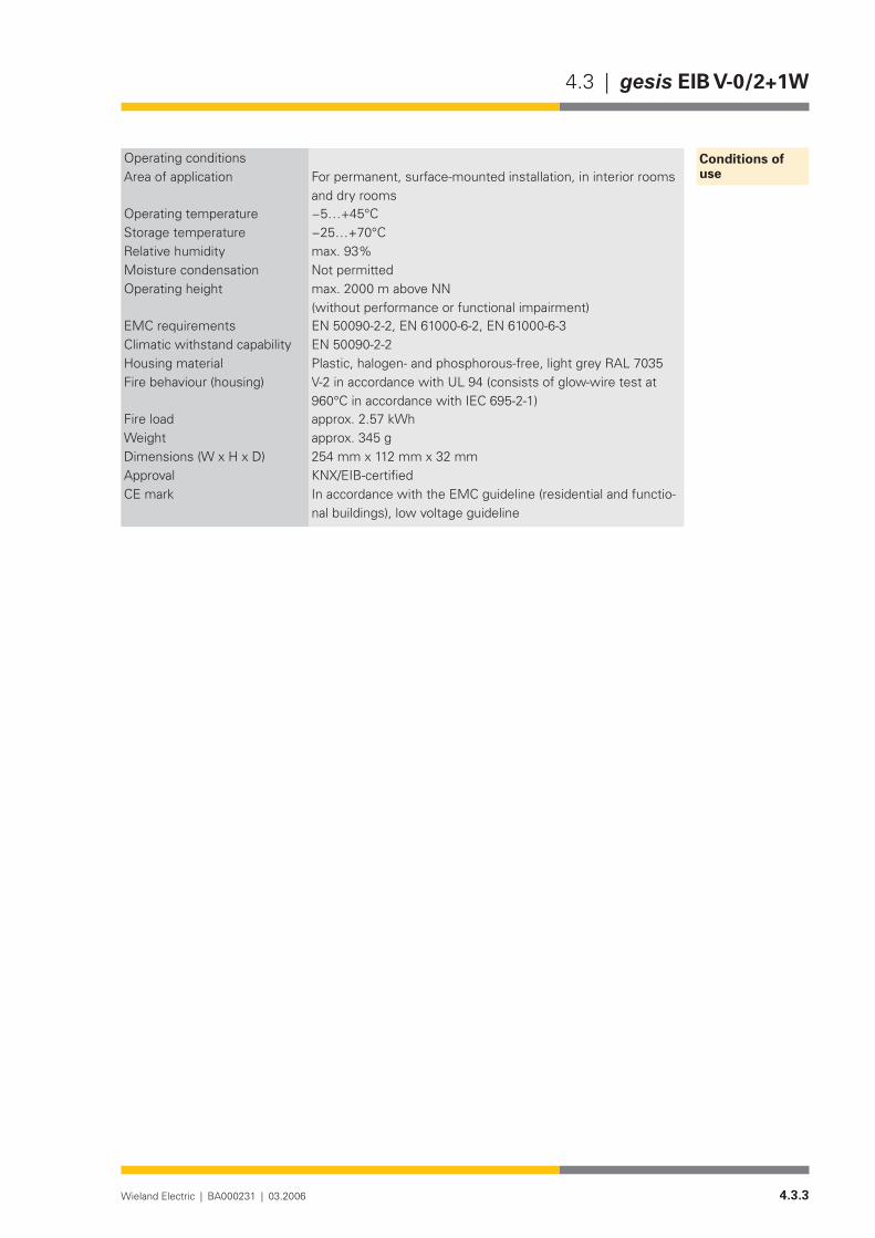
4.3.3Wieland Electric | BA000231 | 03.2006
4.3 | gesis EIB V-0/2+1W
Operating conditionsArea of application For permanent, surface-mounted installation, in interior rooms
and dry roomsOperating temperature −5…+45°CStorage temperature −25…+70°CRelative humidity max. 93%Moisture condensation Not permittedOperating height max. 2000 m above NN
(without performance or functional impairment)EMC requirements EN 50090-2-2, EN 61000-6-2, EN 61000-6-3 Climatic withstand capability EN 50090-2-2Housing material Plastic,halogen-andphosphorous-free,lightgreyRAL7035Fire behaviour (housing) V-2 in accordance with UL 94 (consists of glow-wire test at
960°CinaccordancewithIEC695-2-1)Fire load approx.2.57kWhWeight approx. 345 gDimensions (W x H x D) 254 mm x 112 mm x 32 mmApproval KNX/EIB-certifiedCE mark In accordance with the EMC guideline (residential and functio-
nal buildings), low voltage guideline
Conditions of use

4.3.4 Wieland Electric | BA000231 | 03.2006
gesis EIB V-0/2+1W | 4.3
Installation
Type of installation• Fixing with two screwsRecommended screws • 4.5 mm x 40 mm, when using 6 mm plugsInterval between bore holes• X = 230 mm / Y = 64,5 mmInterval between bore holes• NoneAdditional insulation• Not required
�
����������������
�������
110
13,7
64,5
5,5
5,5
10
12
230,3
7,5
2
EIB V-0/2+1W
254
gesis
ind.
230V~
m
A3: 8A cos =13A cos =0,4
A1/A2: 16A
A1/A2PEN
V-0/2+1WAREA LINE DEVICE
83.020.0212.0
2 OUTPUTS
EIB
1 SHUTTER OUTPUT
PHYSICAL ADDRESS:
PROGRAM
N PEA3
M1~ AufAb
A2/L2A1/L1 A3/L3
Outputs A1...A3 N LPEN LPE
1~M AufAb
2 PEN 1
1 (L1)
2 (L2)
PE
N
3 (L3)
-+
wielandw
gesis
32
50/60Hz; 16A230/400V
Mains voltage input
EIB bus connectionProgramming button
LED display

4.3.5Wieland Electric | BA000231 | 03.2006
4.3 | gesis EIB V-0/2+1W
Accessories
Accessories for 83.020.0212.x (gesis EIB V-0/2+1W and gesis EIB V-0/2+1W 1PH)Incoming supply when using the flat cable •system(7pole)7poleflatcable• 00.702.0323.9EIB adapter• 93.421.0853.0Mains adapter• 92.051.0353.1
Incoming supply via combination connector (EST 3i5)Combination distribution block• 93.550.0053.1Combination connector, female connector• 93.551.0553.1Combination starter cable, female – free end• 94.553.x003.7(x=Lengthinmetres)Combination extension cable, female – male• 94.553.x000.7(x=Lengthinmetres)
Separate incoming supply for mains (GST 18i5) and EIB (BST 14i2)Mains, female connector, screw connection• 92.953.3053.1Mains, starter lead, female – free end• 92.258.x003.1 (x = Length in metres)Mains, extender lead, female – male• 92.258.x000.1 (x = Length in metres)EIB, female connector, spring-loaded connection• 93.421.0553.1EIB, starter lead, female – free end• 94.425.x003.7(x=Lengthinmetres)EIB, extender lead, female – male• 94.425.x000.7(x=Lengthinmetres)
EIB branch (BST 14i2) when using the combination distribution blockEIB, male connector, spring-loaded connection• 93.422.0553.1EIB, starter lead, male – free end• 94.425.x004.7(x=Lengthinmetres)EIB, extender lead, female – male• 94.425.x000.7(x=Lengthinmetres)
Switch outputs (GST 18i3)Male connector, spring-loaded connection• 93.934.0053.1Starter lead, male – free end• 92.232.x004.1 (x = Length in metres)Extender lead, male – female• 92.232.x000.1 (x = Length in metres)
Shutter outputs (GST 18i4)Male connector, spring-loaded connection• 93.944.1053.1Starter lead, male – free end• 92.207.x004.1(x=Lengthinmetres)Extender lead, male – female• 92.207.x000.1(x=Lengthinmetres)
SoftwareProduct database for import in ETS2 from version •V1.1
www.gesis.com (see under Info Service/Download/gesis product database)
Diskette• 00.000.0066.1

4.3.6 Wieland Electric | BA000231 | 03.2006
gesis EIB V-0/2+1W | 4.3
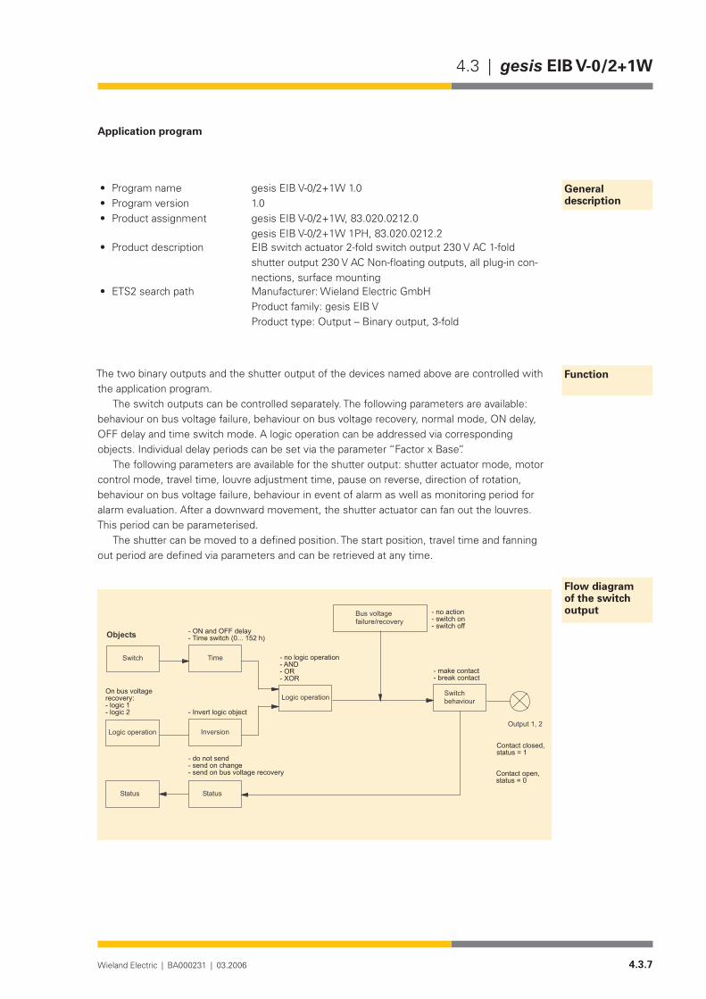
4.3.7Wieland Electric | BA000231 | 03.2006
4.3 | gesis EIB V-0/2+1W
Application program
• Program name gesis EIB V-0/2+1W 1.0Program version• 1.0Product assignment• gesis EIB V-0/2+1W, 83.020.0212.0
gesis EIB V-0/2+1W 1PH, 83.020.0212.2Product description• EIB switch actuator 2-fold switch output 230 V AC 1-fold
shutter output 230 V AC Non-floating outputs, all plug-in con-nections, surface mounting
ETS2 search path• Manufacturer: Wieland Electric GmbH Product family: gesis EIB V Product type: Output – Binary output, 3-fold
The two binary outputs and the shutter output of the devices named above are controlled with the application program.
The switch outputs can be controlled separately. The following parameters are available: behaviour on bus voltage failure, behaviour on bus voltage recovery, normal mode, ON delay, OFF delay and time switch mode. A logic operation can be addressed via corresponding objects. Individual delay periods can be set via the parameter “Factor x Base”.
The following parameters are available for the shutter output: shutter actuator mode, motor control mode, travel time, louvre adjustment time, pause on reverse, direction of rotation, behaviour on bus voltage failure, behaviour in event of alarm as well as monitoring period for alarm evaluation. After a downward movement, the shutter actuator can fan out the louvres. This period can be parameterised.
The shutter can be moved to a defined position. The start position, travel time and fanning out period are defined via parameters and can be retrieved at any time.
General description
Function
Flow diagram of the switch output
�����������������������������������������������������������
������ ������
��������������� ���������
���������������������
�����������������������������������������
������� ��������������������������������������������
����������
���������������������������
����������������������������������
����������������������������������
��������������� ���������������
�����������������������������
�������������������������
�����������������������
�����������
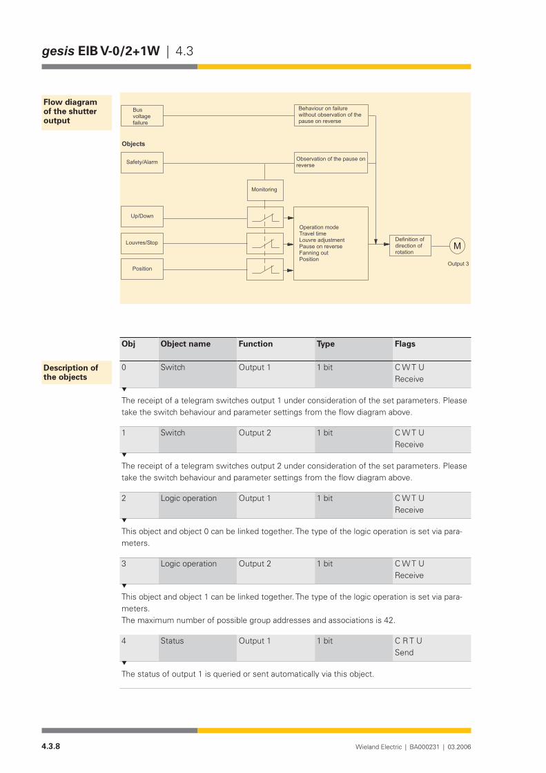
4.3.8 Wieland Electric | BA000231 | 03.2006
gesis EIB V-0/2+1W | 4.3
Obj Object name Function Type Flags
0 Switch Output 1 1 bit C W T UReceive
The receipt of a telegram switches output 1 under consideration of the set parameters. Please take the switch behaviour and parameter settings from the flow diagram above.
1 Switch Output 2 1 bit C W T UReceive
The receipt of a telegram switches output 2 under consideration of the set parameters. Please take the switch behaviour and parameter settings from the flow diagram above.
2 Logic operation Output 1 1 bit C W T UReceive
This object and object 0 can be linked together. The type of the logic operation is set via para-meters.
3 Logic operation Output 2 1 bit C W T UReceive
This object and object 1 can be linked together. The type of the logic operation is set via para-meters.The maximum number of possible group addresses and associations is 42.
4 Status Output 1 1 bit C R T USend
The status of output 1 is queried or sent automatically via this object.
Flow diagram of the shutter output
������������
�������
������������
��������
�������
�����������������
����������
�����������������������������������������������������������������������������
��������������������������������������������������������������
����������������������������������
��������
���������������������������������
�
Description of the objects

4.3.9Wieland Electric | BA000231 | 03.2006
4.3 | gesis EIB V-0/2+1W
Obj Object name Function Type Flags
5 Status Output 2 1 bit C R T USend
The status of output 2 is queried or sent automatically via this object.
6 Safety/Alarm Output 3 1 bit C W T UReceive
The receipt of a ‘1’ telegram triggers the actions set in the parameters in the event of an alarm and disables the output for further operation. The alarm is also activated if the parameterised monitoring period has elapsed without a ‘0’ telegram being received at this object. A ‘0’ tele-gram cancels this alarm and enables operation again.
7 Up/Down Output 3 1 bit C W T UReceive
A telegram received with the useful information ‘0’ controls the ‘Up’ branch in the default setting. A ‘1’ telegram controls the ‘Down’ branch.
8 Louvres/Stop Output 3 1 bit C W T UReceive
A louvre step is triggered for each received telegram. In the default parameter setting, a ‘0’ te-legram tilts the louvres open. A ‘1’ telegram tilts them closed. If the shutter is moving, a ‘Stop’ command is triggered. If the output is parameterised as a roller blind or motor, both telegrams cause the output relay to be switched to the neutral middle position (stop).
9 Position Output 3 1 bit C W T UReceive
The receipt of a ‘0’ telegram retrieves the values set in position 1. The receipt of a ‘1’ telegram retrieves the values set in position 2.
The maximum number of possible group addresses and associations is 42.

4.3.10 Wieland Electric | BA000231 | 03.2006
gesis EIB V-0/2+1W | 4.3
Parameterisation
Default settings are printed in bold type.
Parameters Settings
Behaviour on bus voltage recovery no actionswitch onswitch off
This parameter determines how the bistable relay behaves on bus voltage recovery. If “no ac-tion” is set, the relay remains in the current position. If “switch on” or “switch off” is selected, the corresponding state is created.
Behaviour on bus voltage failure no actionswitch onswitch off
This parameter determines how the bistable relay behaves on bus voltage failure. If “no ac-tion” is set, the relay remains in the current position. If “switch on” or “switch off” is selected, the corresponding state is created.
Switch behaviour make contactbreak contact
To achieve maximum flexibility, the relay can be parameterised as a make contact or break contact. This parameter engages directly with the relay and acts as an inversion of the output.
Status read onlysend on change
The status of the output relay can be sent automatically on the bus after a change (“send on change”).
Status on bus voltage recovery(only visible if the “Status” parameter is set to “send on change”)
do not sendsend
This parameter defines whether the status is sent automatically on bus voltage recovery. If “send” is set, an excessive bus load can arise on bus voltage recovery.
Use logic operation noyes
In the setting “no”, the object “Logic operation” is not taken into account. If “yes” is selected, further parameters are displayed for defining the logic operation. The object value “Logic ope-ration” is then taken into account. The logical connection is carried out between the objects “Switch” and “Logic operation” of the respective output.
Output 1/GeneralOutput 2/General
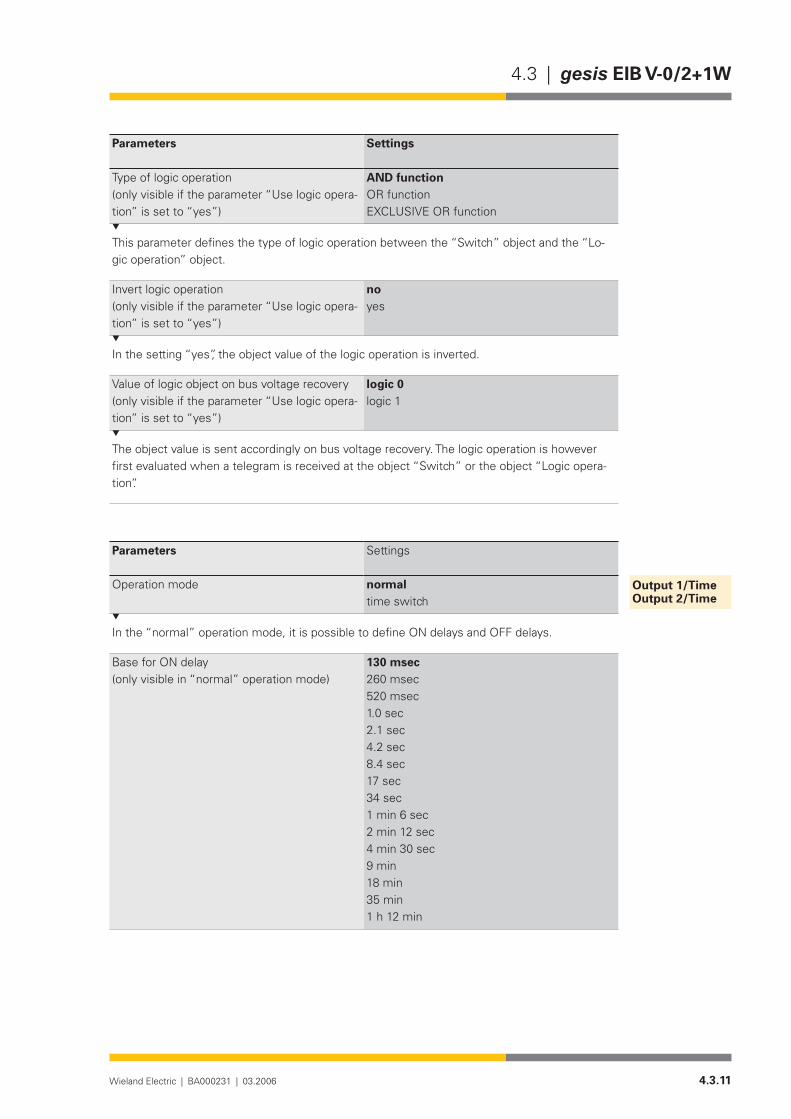
4.3.11Wieland Electric | BA000231 | 03.2006
4.3 | gesis EIB V-0/2+1W
Parameters Settings
Type of logic operation(only visible if the parameter “Use logic opera-tion” is set to “yes”)
AND functionOR functionEXCLUSIVE OR function
This parameter defines the type of logic operation between the “Switch” object and the “Lo-gic operation” object.
Invert logic operation(only visible if the parameter “Use logic opera-tion” is set to “yes”)
noyes
In the setting “yes”, the object value of the logic operation is inverted.
Value of logic object on bus voltage recovery (only visible if the parameter “Use logic opera-tion” is set to “yes”)
logic 0logic 1
The object value is sent accordingly on bus voltage recovery. The logic operation is however first evaluated when a telegram is received at the object “Switch” or the object “Logic opera-tion”.
Parameters Settings
Operation mode normaltime switch
In the “normal” operation mode, it is possible to define ON delays and OFF delays.
Base for ON delay(only visible in “normal” operation mode)
130 msec260 msec520 msec1.0 sec2.1 sec4.2 sec8.4 sec17sec34 sec1 min 6 sec2 min 12 sec4 min 30 sec9 min18 min35 min1 h 12 min
Output 1/TimeOutput 2/Time

4.3.12 Wieland Electric | BA000231 | 03.2006
gesis EIB V-0/2+1W | 4.3
Parameters Settings
FactorforONdelay(0-127)(only visible in “normal” operation mode)
0
Period for ON delay = Base x Factor. The parameters “Base for ON delay” and “Factor for ON delay” define the duration of the ON delay. This period is the time which elapses on receipt of a ‘1’ telegram at the object “Switch” until a logic 1 is passed onto the evaluation of the logic operation (see flow diagram).
Base for OFF delay 130 msec260 msec520 msec1.0 sec2.1 sec4.2 sec8.4 sec17sec34 sec1 min 6 sec2 min 12 sec4 min 30 sec9 min18 min35 min1 h 12 min
FactorforOFFdelay(0-127) 0
Period for OFF delay = Base x Factor. Two different values are defined with the parameters “Base for OFF delay” and “Factor for OFF delay” depending on the selection of the operation mode (“normal” or “time switch”).
1. “normal” operation modeThe time delay from the receipt of a ‘0’ telegram at the “Switch” object of the respective out-put until the transmission of a logic 0 to the evaluation of the logic operation.2. “time switch” operation modePeriod for OFF delay = Base x Factor. On receipt of a ‘1’ telegram at the “Switch” object of the respective output, the transmission of a logic 1 to the evaluation of the logic operation is executed immediately. Only then is the delay carried out. After the end of the logic operation, a logic 0 is transmitted automatically to the evaluation of the logic operation. A received ‘0’ telegram is routed immediately to the logic operation.
Parameters Settings
Alarm evaluation inactiveactive
This parameter regulates the evaluation of object 6 (Safety/Alarm). Received telegrams are only evaluated in the setting “active”.
Behaviour in event of alarm(only visible when the alarm evaluation is set to “active”)
raiselowerstop
Output 3/General (Shutter output)

4.3.13Wieland Electric | BA000231 | 03.2006
4.3 | gesis EIB V-0/2+1W
Parameters Settings
Different reactions to the alarm can be defined for different applications.
Base for monitoring time for alarm evaluation(only visible when the alarm evaluation is set to “active)
130 msec260 msec520 msec1.0 sec2.1 sec4.2 sec8.4 sec17sec34 sec1 min 6 sec2 min 12 sec4 min 30 sec9 min18 min35 min1 h 12 min
Factor for monitoring time for alarm evaluation (10-127)(only visible when the alarm evaluation is set to active)
The actuator expects a ‘0’ telegram at object 6 (Safety/Alarm) within the period set in these parameters. This deletes the alarm and sets the internal monitoring period to zero. If no ‘0’ te-legram is received within the monitoring period, the system activates the alarm. The receipt of a ‘1’ telegram immediately deletes the actions set in the parameters in the event of an alarm. It simultaneously disables the actuator channel for further operation.
Behaviour on bus voltage failure no actionraiselowerstop
The output relay can be set to a defined state on bus voltage failure. As no alarm functions are possible on bus voltage failure, this parameter should have the same settings as the parameter “Behaviour in event of alarm”.
Direction of rotation normalinverted
If the direction of rotation has been mixed up during the installation of the motor, the output can be inverted with this parameter.

4.3.14 Wieland Electric | BA000231 | 03.2006
gesis EIB V-0/2+1W | 4.3
Parameters Settings
Operation mode shutter actuator (with travel time)motor control (continuous operation)
This parameter defines whether the output immediately reverts to the neutral relay position after the travel time (“shutter actuator (with travel time)”) or whether the neutral position can only be reached with a stop command (“motor control (continuous operation)”).
Base for travel time(only visible in operation mode “shutter actua-tor (with travel time)”)
0.5 msec8.0 msec130 msec2.1 sec33 sec
Factor for travel time (10-255)(only visible in operation mode “shutter actua-tor (with travel time)”)
48
Duration of travel time = Base x Factor. The time calculated from the “Base for travel time” and “Factor for travel time” indicates how long the output relay remains switched on. Once the parameterised time has elapsed, the relays de-energise the output.
Louvre adjustment(only visible in operation mode “shutter actua-tor (with travel time)”)
active (e.g. shutter)inactive (e.g. blind)
In the setting “active”, a command at the object “Louvres/Stop” is interpreted as a louvre step or stop command. In the setting “inactive”, this command is interpreted purely as a stop instruction.
Base for louvre adjustment(only visible if louvre adjustment is “active”)
0.5 msec8.0 msec130 msec2.1 sec33 sec
Factor for louvre adjustment (10-255)(only visible if louvre adjustment is “active”)
24
Duration of louvre adjustment = Base x Factor. The time calculated from the “Base for louvre adjustment” and “Factor for louvre adjustment” indicates the duration of a louvre step. Once the parameterised time has elapsed, the relays de-energise the output.
Base for pause on reverse 0.5 msec8.0 msec130 msec2.1 sec33 sec
Factor for pause on reverse (10-255) 60
Period for pause on reverse = Base x Factor. As a rapid change in direction with different mo-tors can lead to the relay contacts being damaged, a pause on reverse must be maintained.
Output 3/Shutter

4.3.15Wieland Electric | BA000231 | 03.2006
4.3 | gesis EIB V-0/2+1W
Base for fanning out in lower position(only visible in operation mode “shutter actua-tor (with travel time)”)
0.5 msec8.0 msec130 msec2.1 sec33 sec
Factor for fanning out in lower position (0-255)(only visible in operation mode “shutter actua-tor (with travel time)”)
0
Period for fanning out on reaching the lower limit position = Base x Factor.Once the travel time of a downward movement of the shutter has elapsed, this setting makes it possible to fan out the louvres again. If a long period is selected, the shutter is raised again slightly.
Parameters Settings
Move to position yesno
The shutter can be moved into the required intermediate position with this parameter. This po-sition is not monitored by the actuator but achieved with the help of travel times. These travel times are set via the subsequent parameters.
Start position (only visible if “Move to position” is set to “yes”)
topbottom
The shutter movement is set solely via operating times. It is therefore necessary to define a start position prior to the positioning. On receipt of a telegram (‘0’ = Position 1. ‘1’ = Position 2) at object 9 (“Position”), the shutter is first moved to the start position. To ensure that the shut-ter moves to the start position from any other position, the travel time is used as an operating time (see above). The positioning starts once the travel time has elapsed.
Base for travel time (only visible if “Move to position” is set to “yes”)
0.5 msec8.0 msec130 msec2.1 sec33 sec
Factor for travel time (10-255) 10
The shutter can be moved into the required intermediate position with this parameter. This po-sition is not monitored by the actuator but achieved with the help of travel times. These travel times are set via the subsequent parameters.
Base for fanning out (only visible if “Move to position” is set to “yes”)
0.5 msec8.0 msec130 msec2.1 sec33 sec
Factor for fanning out (0-255)(only visible if “Move to position” is set to “yes”)
0
Output 3/Position 1Output 3/Position 2

4.3.16 Wieland Electric | BA000231 | 03.2006
gesis EIB V-0/2+1W | 4.3
Period for fanning out = Base x Factor. Once the travel time for positioning the shutter has elapsed, this setting makes it possible to fan out the louvres again. The parameters “Base for fanning out” and “Factor for fanning out” determine the extent to which the shutter should be fanned out.

4.3.17Wieland Electric | BA000231 | 03.2006
4.3 | gesis EIB V-0/2+1W 1PH
gesis EIB V-0/2+1W 1PH
Product description
Designation• Combi actuator, 3-fold, 1-phaseType• gesis EIB V-0/2+1W 1PHPart number• 83.020.0212.2Device type• EIB switch actuator, 3-fold, 230V AC Non-floating switch out-
puts (2 binary outputs/1 shutter output)Design• Device with plug-in connections for surface mounting in enc-
losed rooms, fixing with two screws ETS2 application program• gesis EIB V-0/2+1W 1.0
Function
The combi actuator receives telegrams via the EIB bus and switches two independent electrical loads and a shutter motor via relays or similar loads with 230 V AC nominal voltage. The switch outputs are non-floating. That means that each output is already linked internally with the po-tentials N, PE and linked with an outer conductor of the mains voltage via a corresponding relay contact.
Various time functions, logic operations, contact type of the relay, status object, behaviour on bus voltage failure and bus voltage recovery can be set using parameters. With regard to the shutter output, travel times, step adjustment, pause on reverse, alarm behaviour and alarm periods, reversal of the direction of rotation, two positions and behaviour on bus voltage failure can be set. The shutter always stops on bus voltage recovery.
The bus voltage is used to switch the relay on and off.The parameterisation and operation of the device requires application software. It is loaded
into the device using EIB Tool Software (ETS2).
Functional elements
Programming button• Pressing the programming button switches the programming mode on or off (toggle function).
LED (red)• The LED indicates whether the programming mode is active.
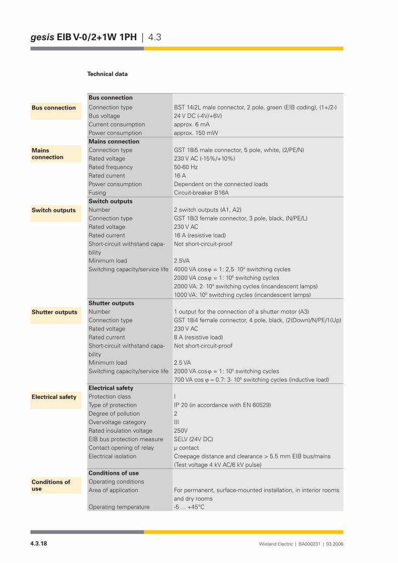
4.3.18 Wieland Electric | BA000231 | 03.2006
gesis EIB V-0/2+1W 1PH | 4.3
Technical data
Bus connection
Connection type BST 14i2L male connector, 2 pole, green (EIB coding), (1+/2-)Bus voltage 24 V DC (-4V/+6V)Current consumption approx. 6 mAPower consumption approx. 150 mWMains connectionConnection type GST 18i5 male connector, 5 pole, white, (2/PE/N)Rated voltage 230 V AC (-15%/+10%)Rated frequency 50-60 HzRated current 16 APower consumption Dependent on the connected loadsFusing Circuit-breaker B16ASwitch outputsNumber 2 switch outputs (A1, A2)Connection type GST 18i3 female connector, 3 pole, black, (N/PE/L)Rated voltage 230 V ACRated current 16 A (resistive load)Short-circuit withstand capa-bility
Not short-circuit-proof
Minimum load 2.5VASwitching capacity/service life 4000 VA cos ϕ = 1: 2,5 ⋅ 104 switching cycles
2000 VA cos ϕ = 1: 105 switching cycles 2000 VA: 2 ⋅ 104 switching cycles (incandescent lamps) 1000 VA: 105 switching cycles (incandescent lamps)
Shutter outputsNumber 1 output for the connection of a shutter motor (A3)Connection type GST 18i4 female connector, 4 pole, black, (2(Down)/N/PE/1(Up)Rated voltage 230 V ACRated current 8 A (resistive load)Short-circuit withstand capa-bility
Not short-circuit-proof
Minimum load 2.5 VASwitching capacity/service life 2000 VA cos ϕ = 1: 105 switching cycles
700VAcosϕ =0.7:3 ⋅ 105 switching cycles (inductive load)Electrical safetyProtection class IType of protection IP 20 (in accordance with EN 60529)Degree of pollution 2Overvoltage category IIIRated insulation voltage 250VEIB bus protection measure SELV (24V DC)Contact opening of relay µ contactElectrical isolation Creepage distance and clearance > 5.5 mm EIB bus/mains
(Test voltage 4 kV AC/6 kV pulse)Conditions of useOperating conditionsArea of application For permanent, surface-mounted installation, in interior rooms
and dry roomsOperating temperature -5...+45°C
Bus connection
Mains connection
Switch outputs
Shutter outputs
Electrical safety
Conditions of use
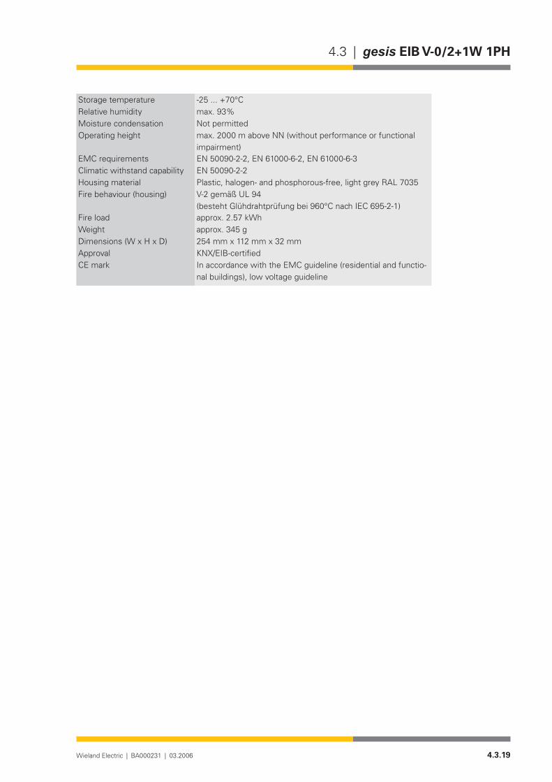
4.3.19Wieland Electric | BA000231 | 03.2006
4.3 | gesis EIB V-0/2+1W 1PH
Storage temperature -25...+70°CRelative humidity max. 93%Moisture condensation Not permittedOperating height max. 2000 m above NN (without performance or functional
impairment)EMC requirements EN 50090-2-2, EN 61000-6-2, EN 61000-6-3Climatic withstand capability EN 50090-2-2Housing material Plastic,halogen-andphosphorous-free,lightgreyRAL7035Fire behaviour (housing) V-2 gemäß UL 94
(bestehtGlühdrahtprüfungbei960°CnachIEC695-2-1)Fire load approx.2.57kWhWeight approx. 345 gDimensions (W x H x D) 254 mm x 112 mm x 32 mmApproval KNX/EIB-certifiedCE mark In accordance with the EMC guideline (residential and functio-
nal buildings), low voltage guideline
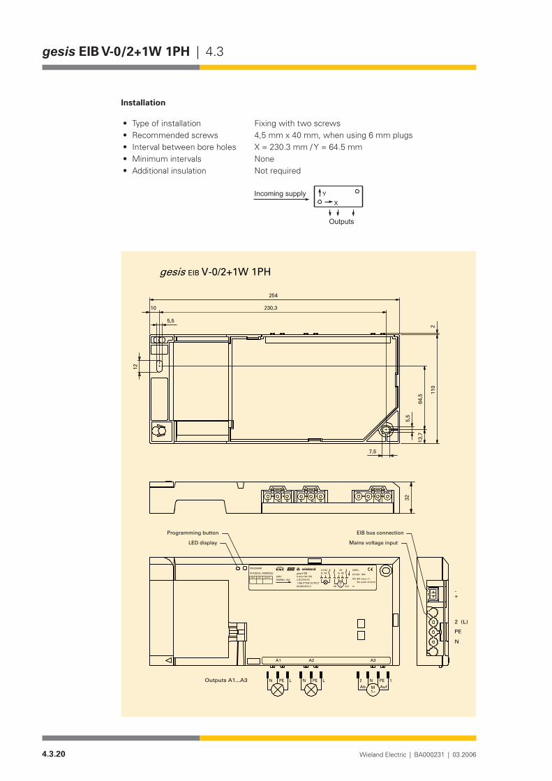
4.3.20 Wieland Electric | BA000231 | 03.2006
gesis EIB V-0/2+1W 1PH | 4.3
Installation
Type of installation• Fixing with two screwsRecommended screws• 4,5 mm x 40 mm, when using 6 mm plugsInterval between bore holes• X = 230.3 mm / Y = 64.5 mmMinimum intervals• NoneAdditional insulation• Not required
�
����������������
�������
V-0/2+1W 1PHEIB
2
7,5
230,3
12
10
5,5
5,5
64,5
13,7
110
254
gesis
A2A1 A3
1N PE2Ab AufM
1~
PE LN PE LNOutputs A1...A3
+-
N
PE
2 (L)
32
Ab Auf1~M
A3PEN
230V50/60Hz; 16A
1 SHUTTER OUTPUT
EIB
2 OUTPUTS
83.020.0212.2
V-0/2+1W 1PHN PEA1/A2
A1/A2: 16A
3A cos =0,4A3: 8A cos =1
m
230V~
ind.
wielandw
gesisDEVICELINEAREA
PHYSICAL ADDRESS:
PROGRAM
Mains voltage input
EIB bus connectionProgramming button
LED display
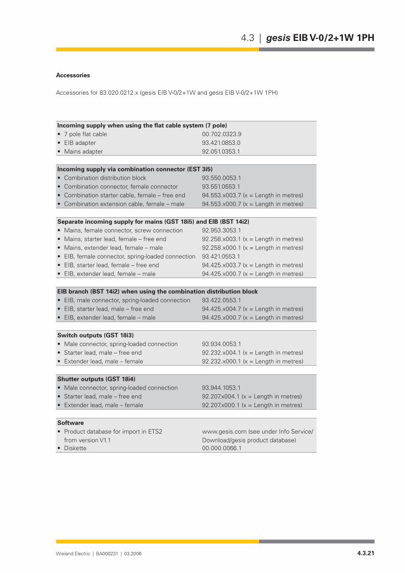
4.3.21Wieland Electric | BA000231 | 03.2006
4.3 | gesis EIB V-0/2+1W 1PH
Accessories
Accessories for 83.020.0212.x (gesis EIB V-0/2+1W and gesis EIB V-0/2+1W 1PH)
Incoming supply when using the flat cable system (7 pole)7poleflatcable• 00.702.0323.9EIB adapter• 93.421.0853.0Mains adapter• 92.051.0353.1
Incoming supply via combination connector (EST 3i5)Combination distribution block• 93.550.0053.1Combination connector, female connector• 93.551.0553.1Combination starter cable, female – free end• 94.553.x003.7(x=Lengthinmetres)Combination extension cable, female – male• 94.553.x000.7(x=Lengthinmetres)
Separate incoming supply for mains (GST 18i5) and EIB (BST 14i2)Mains, female connector, screw connection• 92.953.3053.1Mains, starter lead, female – free end• 92.258.x003.1 (x = Length in metres)Mains, extender lead, female – male• 92.258.x000.1 (x = Length in metres)EIB, female connector, spring-loaded connection• 93.421.0553.1EIB, starter lead, female – free end• 94.425.x003.7(x=Lengthinmetres)EIB, extender lead, female – male• 94.425.x000.7(x=Lengthinmetres)
EIB branch (BST 14i2) when using the combination distribution blockEIB, male connector, spring-loaded connection• 93.422.0553.1EIB, starter lead, male – free end• 94.425.x004.7(x=Lengthinmetres)EIB, extender lead, female – male• 94.425.x000.7(x=Lengthinmetres)
Switch outputs (GST 18i3)Male connector, spring-loaded connection• 93.934.0053.1Starter lead, male – free end• 92.232.x004.1 (x = Length in metres)Extender lead, male – female• 92.232.x000.1 (x = Length in metres)
Shutter outputs (GST 18i4)Male connector, spring-loaded connection• 93.944.1053.1Starter lead, male – free end• 92.207.x004.1(x=Lengthinmetres)Extender lead, male – female• 92.207.x000.1(x=Lengthinmetres)
SoftwareProduct database for import in ETS2 •from version V1.1
www.gesis.com (see under Info Service/Download/gesis product database)
Diskette• 00.000.0066.1

4.3.22 Wieland Electric | BA000231 | 03.2006
gesis EIB V-0/2+1W 1PH | 4.3

4.3.23Wieland Electric | BA000231 | 03.2006
4.3 | gesis EIB V-0/2+1W 1PH
Application program
• Program name gesis EIB V-0/2+1W 1.0Program version• 1.0Product assignment• gesis EIB V-0/2+1W, 83.020.0212.0
gesis EIB V-0/2+1W 1PH, 83.020.0212.2Product description• EIB switch actuator 2-fold switch output 230 V AC 1-fold
shutter output 230 V AC Non-floating outputs, all plug-in con-nections, surface mounting
ETS2 search path• Manufacturer: Wieland Electric GmbH Product family: gesis EIB V Product type: Output – Binary output, 3-fold
The two binary outputs and the shutter output of the devices named above are controlled with the application program.
The switch outputs can be controlled separately. The following parameters are available: behaviour on bus voltage failure, behaviour on bus voltage recovery, normal mode, ON delay, OFF delay and time switch mode. A logic operation can be addressed via corresponding objects. Individual delay periods can be set via the parameter “Factor x Base”.
The following parameters are available for the shutter output: shutter actuator mode, motor control mode, travel time, louvre adjustment time, pause on reverse, direction of rotation, behaviour on bus voltage failure, behaviour in event of alarm as well as monitoring period for alarm evaluation. After a downward movement, the shutter actuator can fan out the louvres. This period can be parameterised.
The shutter can be moved to a defined position. The start position, travel time and fanning out period are defined via parameters and can be retrieved at any time.
General description
Function
Flow diagram of the switch output
�����������������������������������������������������������
������ ������
��������������� ���������
���������������������
�����������������������������������������
������� ��������������������������������������������
����������
���������������������������
����������������������������������
����������������������������������
��������������� ���������������
�����������������������������
�������������������������
�����������������������
�����������
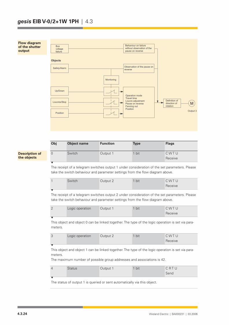
4.3.24 Wieland Electric | BA000231 | 03.2006
gesis EIB V-0/2+1W 1PH | 4.3
Obj Object name Function Type Flags
0 Switch Output 1 1 bit C W T UReceive
The receipt of a telegram switches output 1 under consideration of the set parameters. Please take the switch behaviour and parameter settings from the flow diagram above.
1 Switch Output 2 1 bit C W T UReceive
The receipt of a telegram switches output 2 under consideration of the set parameters. Please take the switch behaviour and parameter settings from the flow diagram above.
2 Logic operation Output 1 1 bit C W T UReceive
This object and object 0 can be linked together. The type of the logic operation is set via para-meters.
3 Logic operation Output 2 1 bit C W T UReceive
This object and object 1 can be linked together. The type of the logic operation is set via para-meters.The maximum number of possible group addresses and associations is 42.
4 Status Output 1 1 bit C R T USend
The status of output 1 is queried or sent automatically via this object.
Flow diagram of the shutter output
������������
�������
������������
��������
�������
�����������������
����������
�����������������������������������������������������������������������������
��������������������������������������������������������������
����������������������������������
��������
���������������������������������
�
Description of the objects
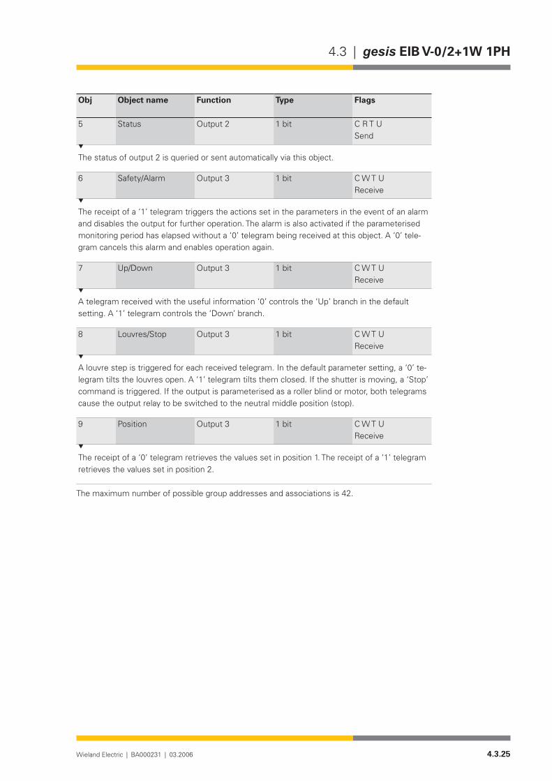
4.3.25Wieland Electric | BA000231 | 03.2006
4.3 | gesis EIB V-0/2+1W 1PH
Obj Object name Function Type Flags
5 Status Output 2 1 bit C R T USend
The status of output 2 is queried or sent automatically via this object.
6 Safety/Alarm Output 3 1 bit C W T UReceive
The receipt of a ‘1’ telegram triggers the actions set in the parameters in the event of an alarm and disables the output for further operation. The alarm is also activated if the parameterised monitoring period has elapsed without a ‘0’ telegram being received at this object. A ‘0’ tele-gram cancels this alarm and enables operation again.
7 Up/Down Output 3 1 bit C W T UReceive
A telegram received with the useful information ‘0’ controls the ‘Up’ branch in the default setting. A ‘1’ telegram controls the ‘Down’ branch.
8 Louvres/Stop Output 3 1 bit C W T UReceive
A louvre step is triggered for each received telegram. In the default parameter setting, a ‘0’ te-legram tilts the louvres open. A ‘1’ telegram tilts them closed. If the shutter is moving, a ‘Stop’ command is triggered. If the output is parameterised as a roller blind or motor, both telegrams cause the output relay to be switched to the neutral middle position (stop).
9 Position Output 3 1 bit C W T UReceive
The receipt of a ‘0’ telegram retrieves the values set in position 1. The receipt of a ‘1’ telegram retrieves the values set in position 2.
The maximum number of possible group addresses and associations is 42.
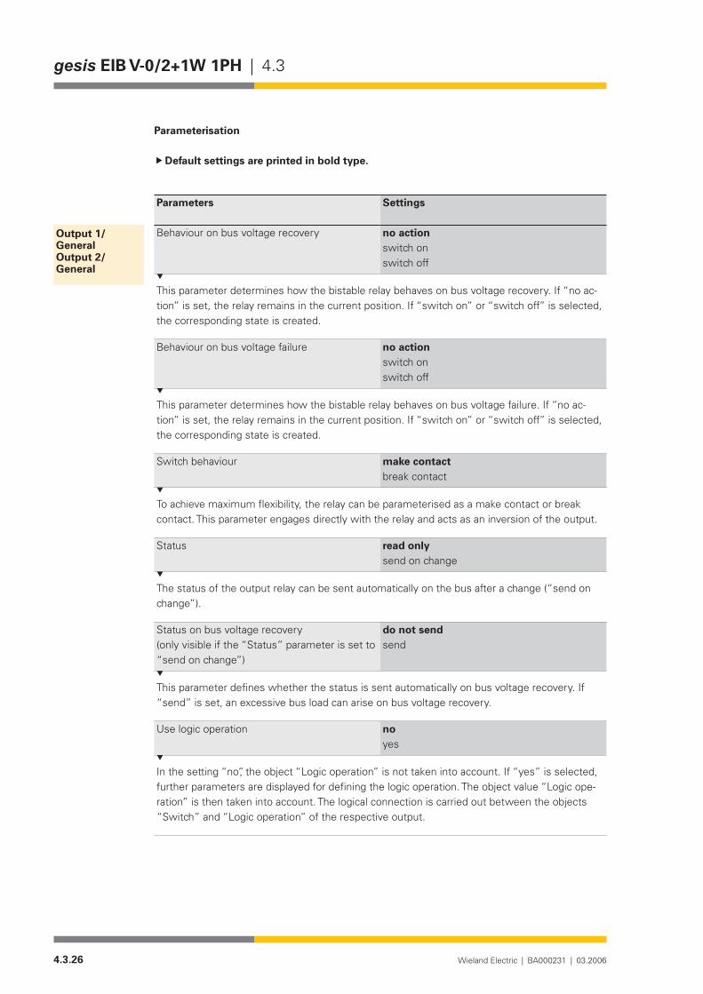
4.3.26 Wieland Electric | BA000231 | 03.2006
gesis EIB V-0/2+1W 1PH | 4.3
Parameterisation
Default settings are printed in bold type.
Parameters Settings
Behaviour on bus voltage recovery no actionswitch onswitch off
This parameter determines how the bistable relay behaves on bus voltage recovery. If “no ac-tion” is set, the relay remains in the current position. If “switch on” or “switch off” is selected, the corresponding state is created.
Behaviour on bus voltage failure no actionswitch onswitch off
This parameter determines how the bistable relay behaves on bus voltage failure. If “no ac-tion” is set, the relay remains in the current position. If “switch on” or “switch off” is selected, the corresponding state is created.
Switch behaviour make contactbreak contact
To achieve maximum flexibility, the relay can be parameterised as a make contact or break contact. This parameter engages directly with the relay and acts as an inversion of the output.
Status read onlysend on change
The status of the output relay can be sent automatically on the bus after a change (“send on change”).
Status on bus voltage recovery(only visible if the “Status” parameter is set to “send on change”)
do not sendsend
This parameter defines whether the status is sent automatically on bus voltage recovery. If “send” is set, an excessive bus load can arise on bus voltage recovery.
Use logic operation noyes
In the setting “no”, the object “Logic operation” is not taken into account. If “yes” is selected, further parameters are displayed for defining the logic operation. The object value “Logic ope-ration” is then taken into account. The logical connection is carried out between the objects “Switch” and “Logic operation” of the respective output.
Output 1/GeneralOutput 2/General

4.3.27Wieland Electric | BA000231 | 03.2006
4.3 | gesis EIB V-0/2+1W 1PH
Parameters Settings
Type of logic operation(only visible if the parameter “Use logic opera-tion” is set to “yes”)
AND functionOR functionEXCLUSIVE OR function
This parameter defines the type of logic operation between the “Switch” object and the “Lo-gic operation” object.
Invert logic operation(only visible if the parameter “Use logic opera-tion” is set to “yes”)
noyes
In the setting “yes”, the object value of the logic operation is inverted.
Value of logic object on bus voltage recovery (only visible if the parameter “Use logic opera-tion” is set to “yes”)
logic 0logic 1
The object value is sent accordingly on bus voltage recovery. The logic operation is however first evaluated when a telegram is received at the object “Switch” or the object “Logic opera-tion”.
Parameters Settings
Operation mode normaltime switch
In the “normal” operation mode, it is possible to define ON delays and OFF delays.
Base for ON delay(only visible in “normal” operation mode)
130 msec260 msec520 msec1.0 sec2.1 sec4.2 sec8.4 sec17sec34 sec1 min 6 sec2 min 12 sec4 min 30 sec9 min18 min35 min1 h 12 min
FactorforONdelay(0-127)(only visible in “normal” operation mode)
0
Period for ON delay = Base x Factor. The parameters “Base for ON delay” and “Factor for ON delay” define the duration of the ON delay. This period is the time which elapses on receipt of a ‘1’ telegram at the object “Switch” until a logic 1 is passed onto the evaluation of the logic operation (see flow diagram).
Output 1/TimeOutput 2/Time
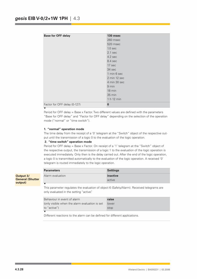
4.3.28 Wieland Electric | BA000231 | 03.2006
gesis EIB V-0/2+1W 1PH | 4.3
Base for OFF delay 130 msec260 msec520 msec1.0 sec2.1 sec4.2 sec8.4 sec17sec34 sec1 min 6 sec2 min 12 sec4 min 30 sec9 min18 min35 min1 h 12 min
FactorforOFFdelay(0-127) 0
Period for OFF delay = Base x Factor. Two different values are defined with the parameters “Base for OFF delay” and “Factor for OFF delay” depending on the selection of the operation mode (“normal” or “time switch”).
1. “normal” operation modeThe time delay from the receipt of a ‘0’ telegram at the “Switch” object of the respective out-put until the transmission of a logic 0 to the evaluation of the logic operation. 2. “time switch” operation modePeriod for OFF delay = Base x Factor. On receipt of a ‘1’ telegram at the “Switch” object of the respective output, the transmission of a logic 1 to the evaluation of the logic operation is executed immediately. Only then is the delay carried out. After the end of the logic operation, a logic 0 is transmitted automatically to the evaluation of the logic operation. A received ‘0’ telegram is routed immediately to the logic operation.
Parameters Settings
Alarm evaluation inactiveactive
This parameter regulates the evaluation of object 6 (Safety/Alarm). Received telegrams are only evaluated in the setting “active”.
Behaviour in event of alarm(only visible when the alarm evaluation is set to “active”)
raiselowerstop
Different reactions to the alarm can be defined for different applications.
Output 3/General (Shutter output)

4.3.29Wieland Electric | BA000231 | 03.2006
4.3 | gesis EIB V-0/2+1W 1PH
Parameters Settings
Base for monitoring time for alarm evaluation(only visible when the alarm evaluation is set to “active)
130 msec260 msec520 msec1.0 sec2.1 sec4.2 sec8.4 sec17sec34 sec1 min 6 sec2 min 12 sec4 min 30 sec9 min18 min35 min1 h 12 min
Factor for monitoring time for alarm evaluation (10-127)(onlyvisiblewhenthealarmevaluati-on is set to “active)
The actuator expects a ‘0’ telegram at object 6 (Safety/Alarm) within the period set in these parameters. This deletes the alarm and sets the internal monitoring period to zero. If no ‘0’ te-legram is received within the monitoring period, the system activates the alarm. The receipt of a ‘1’ telegram immediately deletes the actions set in the parameters in the event of an alarm. It simultaneously disables the actuator channel for further operation.
Behaviour on bus voltage failure no actionraiselowerstop
The output relay can be set to a defined state on bus voltage failure. As no alarm functions are possible on bus voltage failure, this parameter should have the same settings as the parameter “Behaviour in event of alarm”.
Direction of rotation normalinverted
If the direction of rotation has been mixed up during the installation of the motor, the output can be inverted with this parameter.
Parameters Settings
Operation mode shutter actuator (with travel time)motor control (continuous operation)
This parameter defines whether the output immediately reverts to the neutral relay position after the travel time (“shutter actuator (with travel time)”) or whether the neutral position can only be reached with a stop command (“motor control (continuous operation)”).
Output 3/Shutter

4.3.30 Wieland Electric | BA000231 | 03.2006
gesis EIB V-0/2+1W 1PH | 4.3
Base for travel time(only visible in operation mode “shutter actua-tor (with travel time)”)
0.5 msec8.0 msec130 msec2.1 sec33 sec
Factor for travel time (10-255)(only visible in operation mode “shutter actua-tor (with travel time)”)
48
Duration of travel time = Base x Factor. The time calculated from the “Base for travel time” and “Factor for travel time” indicates how long the output relay remains switched on. Once the parameterised time has elapsed, the relays de-energise the output.
Louvre adjustment(only visible in operation mode “shutter actua-tor (with travel time)”)
active (e.g. shutter)inactive (e.g. blind)
In the setting “active”, a command at the object “Louvres/Stop” is interpreted as a louvre step or stop command. In the setting “inactive”, this command is interpreted purely as a stop instruction.
Base for louvre adjustment(only visible if louvre adjustment is “active”)
0.5 msec8.0 msec130 msec2.1 sec33 sec
Factor for louvre adjustment (10-255)(only visible if louvre adjustment is “active”)
24
Duration of louvre adjustment = Base x Factor. The time calculated from the “Base for louvre adjustment” and “Factor for louvre adjustment” indicates the duration of a louvre step. Once the parameterised time has elapsed, the relays de-energise the output.
Base for pause on reverse 0.5 msec8.0 msec130 msec2.1 sec33 sec
Factor for pause on reverse (10-255) 60
Period for pause on reverse = Base x Factor. As a rapid change in direction with different mo-tors can lead to the relay contacts being damaged, a pause on reverse must be maintained.
Base for fanning out in lower position(only visible in operation mode “shutter actua-tor (with travel time)”)
0.5 msec8.0 msec130 msec2.1 sec33 sec
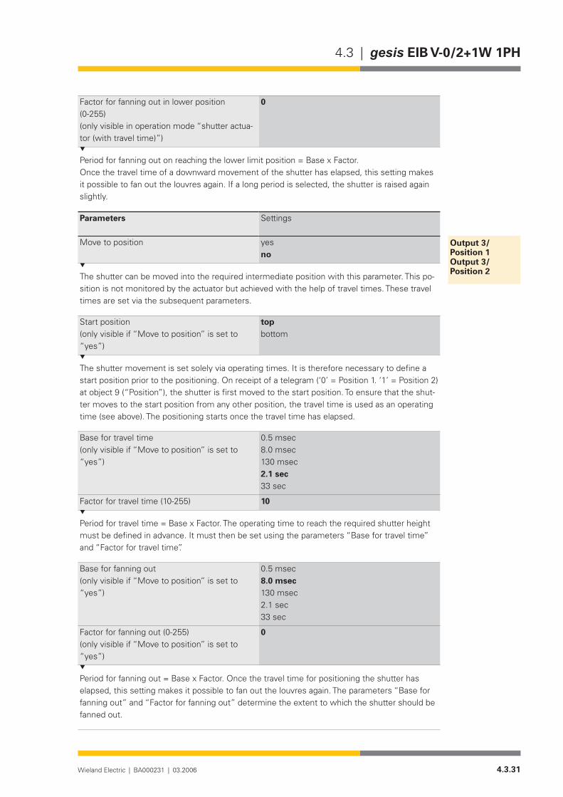
4.3.31Wieland Electric | BA000231 | 03.2006
4.3 | gesis EIB V-0/2+1W 1PH
Factor for fanning out in lower position (0-255)(only visible in operation mode “shutter actua-tor (with travel time)”)
0
Period for fanning out on reaching the lower limit position = Base x Factor.Once the travel time of a downward movement of the shutter has elapsed, this setting makes it possible to fan out the louvres again. If a long period is selected, the shutter is raised again slightly.
Parameters Settings
Move to position yesno
The shutter can be moved into the required intermediate position with this parameter. This po-sition is not monitored by the actuator but achieved with the help of travel times. These travel times are set via the subsequent parameters.
Start position (only visible if “Move to position” is set to “yes”)
topbottom
The shutter movement is set solely via operating times. It is therefore necessary to define a start position prior to the positioning. On receipt of a telegram (‘0’ = Position 1. ‘1’ = Position 2) at object 9 (“Position”), the shutter is first moved to the start position. To ensure that the shut-ter moves to the start position from any other position, the travel time is used as an operating time (see above). The positioning starts once the travel time has elapsed.
Base for travel time (only visible if “Move to position” is set to “yes”)
0.5 msec8.0 msec130 msec2.1 sec33 sec
Factor for travel time (10-255) 10
Period for travel time = Base x Factor. The operating time to reach the required shutter height must be defined in advance. It must then be set using the parameters “Base for travel time” and “Factor for travel time”.
Base for fanning out (only visible if “Move to position” is set to “yes”)
0.5 msec8.0 msec130 msec2.1 sec33 sec
Factor for fanning out (0-255)(only visible if “Move to position” is set to “yes”)
0
Period for fanning out = Base x Factor. Once the travel time for positioning the shutter has elapsed, this setting makes it possible to fan out the louvres again. The parameters “Base for fanning out” and “Factor for fanning out” determine the extent to which the shutter should be fanned out.
Output 3/Position 1Output 3/Position 2

4.3.32 Wieland Electric | BA000231 | 03.2006
gesis EIB V-0/2+1W 1PH | 4.3
4.4.1Wieland Electric | BA000231 | 03.2006
4.4 | gesis EIB V-0/2SD
gesis EIB V-0/2SD
Product description
Designation• Switch/dimming actuator, 2-foldType• gesis EIB V-0/2SDPart number• 83.020.0213.0Device type• EIB switch/dimming actuator 1-10 V, 2-fold, 1-10 V DC Control
outputs for dimmable electronic ballasts with associated, non-floating, 230 V AC switch outputs
Design• Device with plug-in connections for surface mounting in enc-losed rooms, fixing with two screws
ETS2 application program• gesis EIB V-0/2SD 1.0
Function
The switch/dimming actuator receives telegrams from the EIB bus and controls two indepen-dent groups of fluorescent lamps or similar loads via the 1-10 V DC control connection of the ex-ternally connected electronic ballasts (e.g. EVG Dynamic). Each load group can also be switched on or off directly via a switch contact.
The switch outputs are non-floating. That means that each output is already linked internally with the potentials N, PE and linked with an outer conductor of the mains voltage via a cor-responding relay contact. Both 1-10 V DC outputs operate passively. The control voltage must therefore be supplied by externally connected electronic ballasts.
Using parameters, it is possible to set the starting behaviour, dimming behaviour, control vol-tage range, behaviour on bus voltage failure and bus voltage recovery as well as four different lightscenes. A status object is available per output for visualisation purposes. The bus voltage is used for switching the relay on and off. The regulation of the control voltage for the electronic ballast is carried out using an additional internal auxiliary supply. It is generated from the mains voltage. The two ground potentials (−) of the control outputs are linked together.
The parameterisation and operation of the device requires application software. It is loaded into the device using EIB Tool Software (ETS2).
Functional elements
Programming button• Pressing the programming button switches the programming mode on or off (toggle function).
LED (red)• The LED indicates whether the programming mode is active.

4.4.2 Wieland Electric | BA000231 | 03.2006
gesis EIB V-0/2SD | 4.4
Technical data
Bus connectionConnection type BST 14i2F male connector, 2 pole, green (EIB coding), (1+/2-)Bus voltage 24 V DC (-4V/+6V)Current consumption approx. 6 mAPower consumption approx. 150 mWMains connectionConnection type GST 18i5 male connector, 5 pole, black, (1/2/PE/N/3)Rated voltage 230/400 V AC (-15%/+10%)Rated frequency 50-60 HzRated current 16 APower consumption Internally < 1 VA (L2) + externally connected loadsFusing 3 pole circuit-breaker B16A1-10 V interfaces Number 2 control outputsConnection type GST18i5femaleconnector,5pole,pastelblue(…/-/+)(Combi-
nation of switch and control output in one connector)Control voltage 1-10 V DC (from EVG Dynamic)Control current (current sink) max. 50 mA (number of electronic ballasts dependent on type
of ballast, 1 Siemens ballast = approx. 1 mA)Length of control cable max. 100 m (note the specifications of the manufacturer of the
electronic ballast)Device protection Protection against reverse polarity and overload, protection
against improper connection of 230/400 V ACOutputsNumber 2 switch outputs Connection type GST18i5femaleconnector,5pole,pastelblue,(L/N/PE/…)
(Combination of switch and control output in one connector)Rated voltage 230 V AC (mains voltage is used for switching)
Output 1 switches outer conductor L1 Output 2 switches outer conductor L2
Rated current 16A (resistive load)Short-circuit withstand capa-bility
Not short-circuit-proof
Minimum load 2.5 VASwitching capacity/service life 4000 VA cos ϕ = 1: 2.5 ⋅ 104 switching cycles
2000 VA cos ϕ = 1: 105 switching cycles 8 x EVG Dynamic for FL 58 W 12 x EVG Dynamic for FL 36 W 15 x EVG Dynamic for FL 18 W
Electrical safetyProtection class IType of protection IP 20 (in accordance with EN 60529)Degree of pollution 2Overvoltage category IIIRated insulation voltage 250 V EIB bus protection measure EIB bus SELV (24 V DC)Contact opening of relay m contactElectrical isolation
Bus connection
Mains connection
1-10 V interfaces
Outputs
Electrical safety

4.4.3Wieland Electric | BA000231 | 03.2006
4.4 | gesis EIB V-0/2SD
EIB bus <-> mains Creepage distance and clearance > 5.5 mm Test voltage 4 kV AC/6 kV pulse
EIB bus <-> 1-10 V Creepage distance and clearance > 5.5 mm EIB bus/mains test voltage 4 kV AC/6 kV pulse
1-10 V <-> mains Creepage distance and clearance > 3 mm EIB bus/mains test voltage 2.8 kV AC/4 kV pulse
Conditions of useOperating conditionsArea of application For permanent, surface-mounted installation, in interior rooms
and dry roomsOperating temperature −5…+45°CStorage temperature −25…+70°CRelative humidity max. 93%Moisture condensation Not permittedOperating height max. 2000 m above NN
(without performance or functional impairment)EMC requirements EN 50090-2-2, EN 61000-6-2, EN 61000-6-3Climatic withstand capability EN 50090-2-2Housing material Plastic,halogen-andphosphorous-free,lightgreyRAL7035Fire behaviour (housing) V-2 in accordance with UL 94 (consists of glow-wire test at
960°CinaccordancewithIEC695-2-1)Fire load approx. 2.6 kWhWeight approx. 360 gDimensions (W x H x D) 254 mm x 112 mm x 32 mmApproval KNX/EIB-certifiedCE mark In accordance with the EMC guideline (residential and functio-
nal buildings), low voltage guideline
INSTAllATION NOTES
The 1-10 V control interfaces are electrically isolated from the mains voltage by basic insulation (Ui = 250 V). This is not protection by safety separation. There is therefore no safety extra-low voltage for the 1-10 V interfaces. During installation, it is therefore ne-cessary to use cable and connectors which are approved for 230 V. It is possible to lay the control and mains voltage together in one cable (see DIN VDE 0100 520 section 6).
Conditions of use

4.4.4 Wieland Electric | BA000231 | 03.2006
gesis EIB V-0/2SD | 4.4
Installation
Type of installation• Fixing with two screwsRecommended screws • 4.5 mm x 40 mm, when using 6 mm plugsInterval between bore holes • X = 230.3 mm / Y = 64.5 mmMinimum intervals• NoneAdditional insulation• Not required
�
����������������
�������
254
110
13,7
64,5
5,5
5,5
10
12
230,3
7,5
2
EIB V-0/2SDgesis
A2/L2A1/L1
+-
3 (L3)
N
PE
2 (L2)
1 (L1)
N PEL - ++-L PEN
32
1-10V230V~16Am
OUTPUTS 1-10V
EIB V-0/2SD
83.020.0213.050/60Hz; 16A230/400V 2 SWITCH/DIM
N PE
A1/A2
- +L
wielandw
gesisDEVICELINEAREA
PHYSICAL ADDRESS:
PROGRAM
Switch/dimming outputs A1/A2
Mains voltage input
EIB bus connectionProgramming button
LED display
1-10V230V~
dimmable electonicfluorescent lamp with
ballast 1-10V
230V~
dimmable electonicfluorescent lamp with
ballast 1-10V
1-10V

4.4.5Wieland Electric | BA000231 | 03.2006
4.4 | gesis EIB V-0/2SD
Accessories
Accessories for 83.020.0213.x (gesis EIB V-0/2SD and gesis EIB V-0/2D 1PH)
Incoming supply when using the flat cable system (7 pole)7poleflatcable• 00.702.0323.9EIB adapter• 93.421.0853.0Mains adapter• 92.051.0353.1
Incoming supply via combination connector (EST 2i5)Combination distribution block• 93.550.0053.1Combination connector, female connector• 93.551.0553.1Combination starter cable, female – free end• 94.553.x003.7(x=Lengthinmetres)Combination extension cable, female – male• 94.553.x000.7(x=Lengthinmetres)
Separate incoming supply for mains (GST 18i5) and EIB (BST 14i2)Mains, female connector, screw connection• 92.953.3053.1Mains, starter lead, female – free end• 92.258.x003.1 (x = Length in metres)Mains, extender lead, female – male• 92.258.x000.1 (x = Length in metres)EIB, female connector, spring-loaded connection• 93.421.0553.1EIB, starter lead, female – free end• 94.425.x003.7(x=Lengthinmetres)EIB, extender lead, female – male• 94.425.x000.7(x=Lengthinmetres)
EIB branch (BST 14i2) when using the combination distribution blockEIB, male connector, spring-loaded connection• 93.422.0553.1EIB, starter lead, male – free end• 94.425.x004.7(x=Lengthinmetres)EIB, extender lead, female – male • 94.425.x000.7(x=Lengthinmetres)
Switch/dimming outputs (GST 18i5)Male connector, spring-loaded connection• 92.954.3453.1Starter lead, male – free end• 92.257.x004.9(x=Lengthinmetres)Extender lead, male – female• 92.257.x000.9(x=Lengthinmetres)
SoftwareProduct database for import in ETS2 •from version V1.1
www.gesis.com (see under Info Service/Download/gesis product database)
Diskette• 00.000.0066.1

4.4.6 Wieland Electric | BA000231 | 03.2006
gesis EIB V-0/2SD | 4.4
4.4.7Wieland Electric | BA000231 | 03.2006
4.4 | gesis EIB V-0/2SD
Application program
Program name• gesis EIB V-0/2SD 1.0Program version• 1.0Product assignment• gesis EIB V-0/2SD, 83.020.0213.0
gesis EIB V-0/2SD 1PH, 83.020.0213.2Product description• EIB switch/dimming actuator, 2-fold, 230 V AC (1-10 V) Non-
floating outputs, all plug-in connections, surface mountingETS2 search path• Manufacturer: Wieland Electric GmbH
Product family: gesis EIB V Product type: Dimmer
The two switch/dimming outputs of the devices named above are controlled with the applica-tion program.
The outputs can be controlled separately. The following parameters are available to meet special requirements: behaviour on bus voltage failure, behaviour on bus voltage recovery, upper limit for control voltage, lower limit for control voltage, initial brightness, dimming behaviour as well as evaluation of a lockout. These parameters are available separately for both outputs.
Four different lightscenes can be stored for each output and retrieved via two objects.
Obj Object name Function Type Flags
0 Lock Outputs 1/2 1 bit C W T UReceive
On receipt of a ‘1’ telegram, both outputs are automatically disabled for further operation. The lockout is removed by the receipt of a ‘0’ telegram.
1 Scene 1/2 Outputs 1/2 1 bit C W T UReceive
The parameterised values for scenes 1 and 2 are retrieved with this object. A ‘0’ telegram retrieves scene 1 while a ‘1’ telegram retrieves scene 2.
2 Scene 3/4 Outputs 1/2 1 bit C W T UReceive
The parameterised values for scenes 3 and 4 are retrieved with this object. A ‘0’ telegram retrieves scene 3 while a ‘1’ telegram retrieves scene 4.
3 Switch/Status Output 1 1 bit C W UReceive
The receipt of a ‘1’ telegram switches the output relay on and activates the control output. Ob-ject 0 and the parameter settings are taken into account. If the flag ‘Transmit’ is set, the object sends the status (on/off) of the output after a change.
General description
Function
Description of the objects

4.4.8 Wieland Electric | BA000231 | 03.2006
gesis EIB V-0/2SD | 4.4
Obj Object name Function Type Flags
4 Dimming Output 1 4 bit C W T UReceive
It is possible to modify the control voltage and switch the output relay with this object. Object 0 and the parameter settings are taken into account when switching the relay and regulating the control voltage.
5 Set value Output 1 1 byte C W T UReceive
The control voltage can be set to a specified value via this object. Object 0 and the parameter settings are taken into account when switching the relay and regulating the control voltage.
The maximum number of possible group addresses and associations is 32.
6 Status (value) Output 1 1 byte C R T USend
This object reports the current value of the control voltage. During the dimming process, the object value is only updated when the final value is reached.Example:Object value 0 = offObject value 1 = Parameter setting “Lower limit for control voltage min. brightness”Object value 255 = Parameter setting “Upper limit for control voltage max. brightness”The values between 1 and 255 are divided linearly across the control voltage range.
7 Switch/Status Output 2 1 bit C W UReceive
The receipt of a ‘1’ telegram switches the output relay on and activates the control output. Ob-ject 0 and the parameter settings are taken into account. If the flag ‘Transmit’ is set, the object sends the status (on/off) of the output after a change.
8 Dimming Output 2 4 bit C W T UReceive
It is possible to modify the control voltage and switch the output relay with this object. Object 0 and the parameter settings are taken into account when switching the relay and regulating the control voltage.
9 Set value Output 2 1 byte C W T UReceive
The control voltage can be set to a specified value via this object. Object 0 and the parameter settings are taken into account when switching the relay and regulating the control voltage.

4.4.9Wieland Electric | BA000231 | 03.2006
4.4 | gesis EIB V-0/2SD
Obj Object name Function Type Flags
10 Status (value) Output 2 1 byte C R T USend
This object reports the current value of the control voltage. During the dimming process, the object value is only updated when the final value is reached.
Example:Object value 0 = offObject value 1 = Parameter setting “Lower limit for control voltage min. brightness”Object value 255 = Parameter setting “Upper limit for control voltage max. brightness”The values between 1 and 255 are divided linearly across the control voltage range.
The maximum number of possible group addresses and associations is 46.
Parameterisation
Default settings are printed in bold type.
Parameters Settings
Bus voltage recovery do not changeswitch offminimum brightness10%20%30%40%50%60%70%80%90%100%
This parameter defines the behaviour of the output on bus voltage recovery. The output relay is switched accordingly. The setting “do not change” leads to the adoption of the control voltage value and relay state that existed before bus voltage failure.
Output 1Output 2
4.4.10 Wieland Electric | BA000231 | 03.2006
gesis EIB V-0/2SD | 4.4
Parameters Settings
Bus voltage failure do not changeswitch offminimum brightness10%20%30%40%50%60%70%80%90%100%
This parameter defines the behaviour of the output on bus voltage failure. The output relay is switched accordingly.
Starting value last valueminimum brightness10%20%30%40%50%60%70%80%90%100%
This parameter defines which value the control voltage adopts on receipt of an ‘ON’ telegram at the object “Switch/Status”. The setting “last value” leads to the adoption of the value that existed before switching off.
Switch on/off via dimming ON = yes / OFF = yesON = yes / OFF = noON = no / OFF = yesON = no / OFF = no
This parameter regulates the behaviour of the output on reaching the final dimming values. If dimming should be carried out from the OFF state starting with zero, the option “ON = yes” must be set. If the device should be switched off after reaching the minimum value when dimming from bright to dark, the option “OFF = yes” must be set.
4.4.11Wieland Electric | BA000231 | 03.2006
4.4 | gesis EIB V-0/2SD
Parameters Settings
Dimming time (approx.) 1 sec2 sec4 sec5 sec6 sec9 sec13 sec26 sec50 sec1 min 20 sec15 min30 min45 min1 h1 h 15 min1 h 30 min1 h 45 min
This parameter defines the period in which the control voltage (starting at 0%) reaches 100%.
Dimming value set valuedim to valueset value (only in ON state)dim to value (only in ON state)
This parameter defines the behaviour on receipt of a dimming value. In the setting “set value”, the received brightness value is issued immediately. For “dim to value”, the device is dimmed to the new value according to the set dimming period. If the dimmer is in the OFF state and one of the parameters relating to the ON state is selected (“set value (only in ON state)” / “dim to value (only in ON state)”), no action is carried out. The value is ignored.
Upper limit for control voltage max. brightness 0 volts (approx. 0.6 volts)1 volt2 volts3 volts4 volts5 volts6 volts7volts8 volts9 volts10 volts
The control voltage limit restricts the control voltage to a set value. The upper limit for the control voltage sets the maximum value. This can contribute to increasing the service life of the fluorescent lamp.

4.4.12 Wieland Electric | BA000231 | 03.2006
gesis EIB V-0/2SD | 4.4
Parameters Settings
Lower limit for control voltage min. brightness 0 volts (approx. 0.6 volts)1 volt2 volts3 volts4 volts5 volts6 volts7volts8 volts9 volts10 volts
The control voltage limit restricts the control voltage to a set value. The lower limit for the con-trol voltage sets the minimum value. The minimum voltage is approx. 0.6 volts.
Parameters Settings
Scene 1: Output 1 do not changeswitch offminimum brightness10%20%30%40%50%60%70%80%90%100%
Scene 1: Output 2 do not changeswitch offminimum brightness10%20%30%40%50%60%70%80%90%100%
The two parameters “Scene 1” define the dimming value of the respective output if scene 1 is retrieved via a ‘0’ telegram at object 1. The method of achieving this value is regulated by the parameter “Scene control”.
Scenes
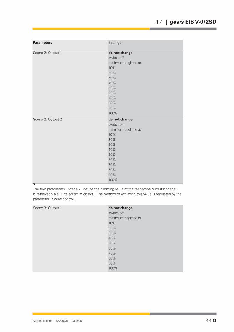
4.4.13Wieland Electric | BA000231 | 03.2006
4.4 | gesis EIB V-0/2SD
Parameters Settings
Scene 2: Output 1 do not changeswitch offminimum brightness10%20%30%40%50%60%70%80%90%100%
Scene 2: Output 2 do not changeswitch offminimum brightness10%20%30%40%50%60%70%80%90%100%
The two parameters “Scene 2” define the dimming value of the respective output if scene 2 is retrieved via a ‘1’ telegram at object 1. The method of achieving this value is regulated by the parameter “Scene control”.
Scene 3: Output 1 do not changeswitch offminimum brightness10%20%30%40%50%60%70%80%90%100%

4.4.14 Wieland Electric | BA000231 | 03.2006
gesis EIB V-0/2SD | 4.4
Parameters Settings
Scene 3: Output 2 do not changeswitch offminimum brightness10%20%30%40%50%60%70%80%90%100%
The two parameters “Scene 3” define the dimming value of the respective output if scene 3 is retrieved via a ‘0’ telegram at object 2. The method of achieving this value is regulated by the parameter “Scene control”.
Scene 4: Output 1 do not changeswitch offminimum brightness10%20%30%40%50%60%70%80%90%100%
Scene 4: Output 2 do not changeswitch offminimum brightness10%20%30%40%50%60%70%80%90%100%
The two parameters “Scene 4” define the dimming value of the respective output if scene 4 is retrieved via a ‘1’ telegram at object 2. The method of achieving this value is regulated by the parameter “Scene control”.

4.4.15Wieland Electric | BA000231 | 03.2006
4.4 | gesis EIB V-0/2SD
Parameters Settings
Scene control: Output 1 set scene valuesdim to scene values
This parameter determines how the control voltage value is achieved. In the setting “dim to scene values”, the regulation of the voltage is carried out under consideration of the parame-terised dimming time. (The starting point for dimming is the value set prior to retrieving the scene).
Scene control: Output 2 set scene valuesdim to scene values
This parameter determines how the control voltage value is achieved. In the setting “dim to scene values”, the regulation of the voltage is carried out under consideration of the parame-terised dimming time. (The starting point for dimming is the value set prior to retrieving the scene).

4.4.16 Wieland Electric | BA000231 | 03.2006
gesis EIB V-0/2SD | 4.4
4.4.17Wieland Electric | BA000231 | 03.2006
4.4 | gesis EIB V-0/2SD 1PH
gesis EIB V-0/2SD 1PH
Product description
Designation• Switch/dimming actuator, 2-fold, 1-phaseType• gesis EIB V-0/2SD 1PHPart number• 83.020.0213.2Device type• EIB switch/dimming actuator 1-10 V, 2-fold, 1-10 V DC Control
outputs for dimmable electronic ballasts with associated, non-floating, 230 V AC switch outputs
Design• Device with plug-in connections for surface mounting in enc-losed rooms, fixing with two screws
ETS2 application program• gesis EIB V-0/2SD 1.0
Function
The switch/dimming actuator receives telegrams from the EIB bus and controls two indepen-dent groups of fluorescent lamps or similar loads via the 1-10 V DC control connection of the ex-ternally connected electronic ballasts (e.g. EVG Dynamic). Each load group can also be switched on or off directly via a switch contact. The switch outputs are non-floating. That means that each output is already linked internally with the potentials N, PE and linked with an outer conductor of the mains voltage via a corresponding relay contact.
Both 1-10 V DC outputs operate passively. The control voltage must therefore be supplied by externally connected electronic ballasts. Using parameters, it is possible to set the starting behaviour, dimming behaviour, control voltage range, behaviour on bus voltage failure and bus voltage recovery as well as four different lightscenes. A status object is available per output for visualisation purposes. The bus voltage is used for switching the relay on and off. The regulation of the control voltage for the electronic ballast is carried out using an additional internal auxili-ary supply. It is generated from the mains voltage. The two ground potentials (−) of the control outputs are linked together.
The parameterisation and operation of the device requires application software. It is loaded into the device using EIB Tool Software (ETS2).
Functional elements
Programming button• Pressing the programming button switches the programming mode on or off (toggle function).
LED (red)• The LED indicates whether the programming mode is active.
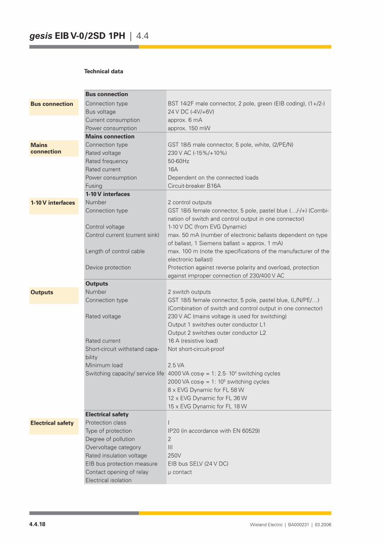
4.4.18 Wieland Electric | BA000231 | 03.2006
gesis EIB V-0/2SD 1PH | 4.4
Technical data
Bus connection
Connection type BST 14i2F male connector, 2 pole, green (EIB coding), (1+/2-)Bus voltage 24 V DC (-4V/+6V)Current consumption approx. 6 mAPower consumption approx. 150 mWMains connectionConnection type GST 18i5 male connector, 5 pole, white, (2/PE/N)Rated voltage 230 V AC (-15%/+10%)Rated frequency 50-60HzRated current 16APower consumption Dependent on the connected loadsFusing Circuit-breaker B16A1-10 V interfacesNumber 2 control outputsConnection type GST18i5femaleconnector,5pole,pastelblue(…/-/+)(Combi-
nation of switch and control output in one connector)Control voltage 1-10 V DC (from EVG Dynamic)Control current (current sink) max. 50 mA (number of electronic ballasts dependent on type
of ballast, 1 Siemens ballast = approx. 1 mA)Length of control cable max. 100 m (note the specifications of the manufacturer of the
electronic ballast)Device protection Protection against reverse polarity and overload, protection
against improper connection of 230/400 V ACOutputsNumber 2 switch outputsConnection type GST18i5femaleconnector,5pole,pastelblue,(L/N/PE/…)
(Combination of switch and control output in one connector)Rated voltage 230 V AC (mains voltage is used for switching)
Output 1 switches outer conductor L1 Output 2 switches outer conductor L2
Rated current 16 A (resistive load)Short-circuit withstand capa-bility
Not short-circuit-proof
Minimum load 2.5 VASwitching capacity/ service life 4000 VA cos ϕ = 1: 2.5 ⋅ 104 switching cycles
2000 VA cos ϕ = 1: 105 switching cycles 8 x EVG Dynamic for FL 58 W 12 x EVG Dynamic for FL 36 W 15 x EVG Dynamic for FL 18 W
Electrical safetyProtection class IType of protection IP20 (in accordance with EN 60529)Degree of pollution 2Overvoltage category IIIRated insulation voltage 250VEIB bus protection measure EIB bus SELV (24 V DC)Contact opening of relay µ contactElectrical isolation
Bus connection
Mains connection
1-10 V interfaces
Outputs
Electrical safety
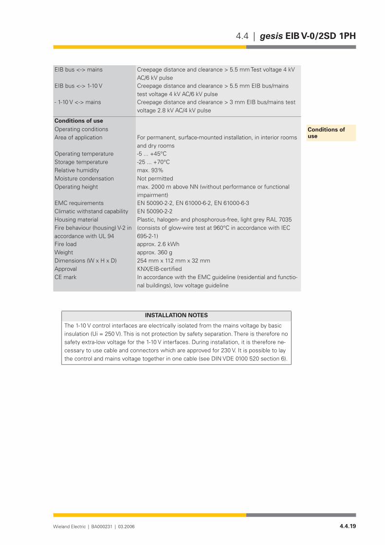
4.4.19Wieland Electric | BA000231 | 03.2006
4.4 | gesis EIB V-0/2SD 1PH
EIB bus <-> mains Creepage distance and clearance > 5.5 mm Test voltage 4 kV AC/6 kV pulse
EIB bus <-> 1-10 V Creepage distance and clearance > 5.5 mm EIB bus/mains test voltage 4 kV AC/6 kV pulse
- 1-10 V <-> mains Creepage distance and clearance > 3 mm EIB bus/mains test voltage 2.8 kV AC/4 kV pulse
Conditions of useOperating conditions Area of application For permanent, surface-mounted installation, in interior rooms
and dry roomsOperating temperature -5...+45°CStorage temperature -25...+70°CRelative humidity max. 93%Moisture condensation Not permittedOperating height max. 2000 m above NN (without performance or functional
impairment)EMC requirements EN 50090-2-2, EN 61000-6-2, EN 61000-6-3Climatic withstand capability EN 50090-2-2Housing material Plastic,halogen-andphosphorous-free,lightgreyRAL7035Fire behaviour (housing) V-2 in accordance with UL 94
(consistsofglow-wiretestat960°CinaccordancewithIEC695-2-1)
Fire load approx. 2.6 kWhWeight approx. 360 gDimensions (W x H x D) 254 mm x 112 mm x 32 mmApproval KNX/EIB-certified CE mark In accordance with the EMC guideline (residential and functio-
nal buildings), low voltage guideline
INSTAllATION NOTES
The 1-10 V control interfaces are electrically isolated from the mains voltage by basic insulation (Ui = 250 V). This is not protection by safety separation. There is therefore no safety extra-low voltage for the 1-10 V interfaces. During installation, it is therefore ne-cessary to use cable and connectors which are approved for 230 V. It is possible to lay the control and mains voltage together in one cable (see DIN VDE 0100 520 section 6).
Conditions of use

4.4.20 Wieland Electric | BA000231 | 03.2006
gesis EIB V-0/2SD 1PH | 4.4
Installation
Type of installation• Fixing with two screwsRecommended screws • 4.5 mm x 40 mm, when using 6 mm plugsInterval between bore holes• X = 230.3 mm/ Y = 64.5 mmMinimum intervals • None Additional insulation • Not required
�
����������������
�������
254
110
13,7
64,5
5,5
5,5
10
12
230,3
7,5
2
EIB V-0/2SD 1PHgesis
A2A1
N PEL - +
1-10V230V~
dimmable electonicfluorescent lamp with
+-L PEN
32
2 (L)
PE
N
-+
Switch/dimming outputs A1/A2
1-10V230V~16Am
OUTPUTS 1-10V
EIB V-0/2SD 1PH
83.020.0213.250/60Hz; 16A230V 2 SWITCH/DIM
N PE
A1/A2
- +L
gesiswielandw
DEVICELINEAREA
PHYSICAL ADDRESS:
PROGRAM
Mains voltage input
EIB bus connectionProgramming button
LED display
ballast 1-10V
1-10V230V~
dimmable electonicfluorescent lamp with
ballast 1-10V

4.4.21Wieland Electric | BA000231 | 03.2006
4.4 | gesis EIB V-0/2SD 1PH
Accessories
Accessories for 83.020.0213.x (gesis EIB V-0/2SD and gesis EIB V-0/2D 1PH)
Incoming supply when using the flat cable system (7 pole)7poleflatcable• 00.702.0323.9EIB adapter• 93.421.0853.0Mains adapter• 92.051.0353.1
Incoming supply via combination connector (EST 2i5)Combination distribution block• 93.550.0053.1Combination connector, female connector• 93.551.0553.1Combination starter cable, female – free end• 94.553.x003.7(x=Lengthinmetres)Combination extension cable, female – male• 94.553.x000.7(x=Lengthinmetres)
Separate incoming supply for mains (GST 18i5) and EIB (BST 14i2)Mains, female connector, screw connection• 92.953.3053.1Mains, starter lead, female – free end• 92.258.x003.1 (x = Length in metres)Mains, extender lead, female – male• 92.258.x000.1 (x = Length in metres)EIB, female connector, spring-loaded connection• 93.421.0553.1EIB, starter lead, female – free end• 94.425.x003.7(x=Lengthinmetres)EIB, extender lead, female – male• 94.425.x000.7(x=Lengthinmetres)
EIB branch (BST 14i2) when using the combination distribution blockEIB, male connector, spring-loaded connection• 93.422.0553.1EIB, starter lead, male – free end• 94.425.x004.7(x=Lengthinmetres)EIB, extender lead, female – male• 94.425.x000.7(x=Lengthinmetres)
Switch/dimming outputs (GST 18i5)Male connector, spring-loaded connection• 92.954.3453.1Starter lead, male – free end• 92.257.x004.9(x=Lengthinmetres)Extender lead, male – female• 92.257.x000.9(x=Lengthinmetres)
SoftwareProduct database for import in ETS2 •from version V1.1
www.gesis.com (see under Info Service/Download/gesis product database)
Diskette• 00.000.0066.1

4.4.22 Wieland Electric | BA000231 | 03.2006
gesis EIB V-0/2SD 1PH | 4.4

4.4.23Wieland Electric | BA000231 | 03.2006
4.4 | gesis EIB V-0/2SD 1PH
Application program
• Program name gesis EIB V-0/2SD 1.0Program version• 1.0Product assignment• gesis EIB V-0/2SD, 83.020.0213.0
gesis EIB V-0/2SD 1PH, 83.020.0213.2Product description• EIB switch/dimming actuator, 2-fold, 230 V AC (1-10 V)
Non-floating outputs, all plug-in connections, surface mountingETS2 search path• Manufacturer: Wieland Electric GmbH
Product family: gesis EIB V Product type: Dimmer
The two switch/dimming outputs of the devices named above are controlled with the applica-tion program.
The outputs can be controlled separately. The following parameters are available to meet special requirements: behaviour on bus voltage failure, behaviour on bus voltage recovery, upper limit for control voltage, lower limit for control voltage, initial brightness, dimming behaviour as well as evaluation of a lockout. These parameters are available separately for both outputs.
Four different lightscenes can be stored for each output and retrieved via two objects.
Obj Object name Function Type Flags
0 Lock Outputs 1/2 1 bit C W T UReceive
On receipt of a ‘1’ telegram, both outputs are automatically disabled for further operation. The lockout is removed by the receipt of a ‘0’ telegram.
1 Scene 1/2 Outputs 1/2 1 bit C W T UReceive
The parameterised values for scenes 1 and 2 are retrieved with this object. A ‘0’ telegram retrieves scene 1 while a ‘1’ telegram retrieves scene 2.
2 Scene 3/4 Outputs 1/2 1 bit C W T UReceive
The parameterised values for scenes 3 and 4 are retrieved with this object. A ‘0’ telegram retrieves scene 3 while a ‘1’ telegram retrieves scene 4.
3 Switch/Status Output 1 1 bit C W UReceive
The receipt of a ‘1’ telegram switches the output relay on and activates the control output. Ob-ject 0 and the parameter settings are taken into account. If the flag ‘Transmit’ is set, the object sends the status (on/off) of the output after a change.
General description
Function
Description of the objects

4.4.24 Wieland Electric | BA000231 | 03.2006
gesis EIB V-0/2SD 1PH | 4.4
Obj Object name Function Type Flags
4 Dimming Output 1 4 bit C W T UReceive
It is possible to modify the control voltage and switch the output relay with this object. Object 0 and the parameter settings are taken into account when switching the relay and regulating the control voltage.
5 Set value Output 1 1 byte C W T UReceive
The control voltage can be set to a specified value via this object. Object 0 and the parameter settings are taken into account when switching the relay and regulating the control voltage.
The maximum number of possible group addresses and associations is 32.
6 Status (value) Output 1 1 byte C R T USend
This object reports the current value of the control voltage. During the dimming process, the object value is only updated when the final value is reached.Example:Object value 0 = offObject value 1 = Parameter setting “Lower limit for control voltage min. brightness”Object value 255 = Parameter setting “Upper limit for control voltage max. brightness”The values between 1 and 255 are divided linearly across the control voltage range.
7 Switch/Status Output 2 1 bit C W UReceive
The receipt of a ‘1’ telegram switches the output relay on and activates the control output. Ob-ject 0 and the parameter settings are taken into account. If the flag ‘Transmit’ is set, the object sends the status (on/off) of the output after a change.
8 Dimming Output 2 4 bit C W T UReceive
It is possible to modify the control voltage and switch the output relay with this object. Object 0 and the parameter settings are taken into account when switching the relay and regulating the control voltage.
9 Set value Output 2 1 byte C W T UReceive
The control voltage can be set to a specified value via this object. Object 0 and the parameter settings are taken into account when switching the relay and regulating the control voltage.
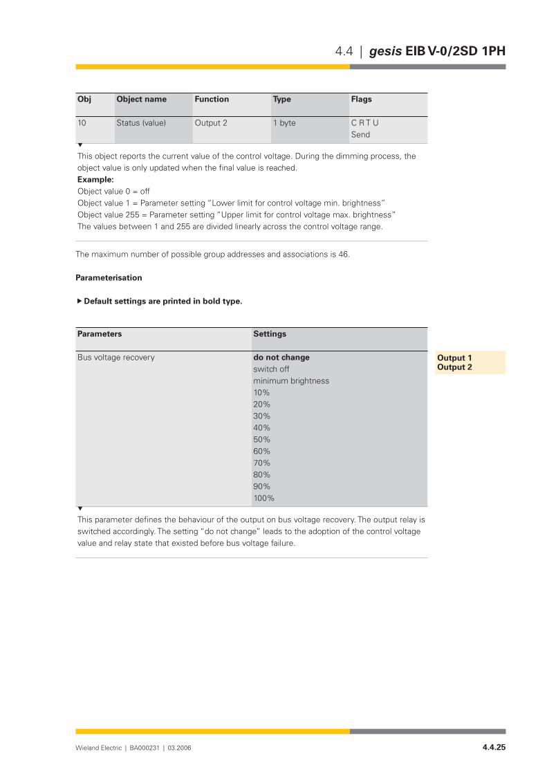
4.4.25Wieland Electric | BA000231 | 03.2006
4.4 | gesis EIB V-0/2SD 1PH
Obj Object name Function Type Flags
10 Status (value) Output 2 1 byte C R T USend
This object reports the current value of the control voltage. During the dimming process, the object value is only updated when the final value is reached.Example:Object value 0 = offObject value 1 = Parameter setting “Lower limit for control voltage min. brightness”Object value 255 = Parameter setting “Upper limit for control voltage max. brightness”The values between 1 and 255 are divided linearly across the control voltage range.
The maximum number of possible group addresses and associations is 46.
Parameterisation
Default settings are printed in bold type.
Parameters Settings
Bus voltage recovery do not changeswitch offminimum brightness10%20%30%40%50%60%70%80%90%100%
This parameter defines the behaviour of the output on bus voltage recovery. The output relay is switched accordingly. The setting “do not change” leads to the adoption of the control voltage value and relay state that existed before bus voltage failure.
Output 1Output 2

4.4.26 Wieland Electric | BA000231 | 03.2006
gesis EIB V-0/2SD 1PH | 4.4
Parameters Settings
Bus voltage failure do not changeswitch offminimum brightness10%20%30%40%50%60%70%80%90%100%
This parameter defines the behaviour of the output on bus voltage failure. The output relay is switched accordingly.
Starting value last valueminimum brightness10%20%30%40%50%60%70%80%90%100%
This parameter defines which value the control voltage adopts on receipt of an ‘ON’ telegram at the object “Switch/Status”. The setting “last value” leads to the adoption of the value that existed before switching off.
Switch on/off via dimming ON = yes / OFF = yesON = yes / OFF = noON = no / OFF = yesON = no / OFF = no
This parameter regulates the behaviour of the output on reaching the final dimming values. If dimming should be carried out from the OFF state starting with zero, the option “ON = yes” must be set. If the device should be switched off after reaching the minimum value when dimming from bright to dark, the option “OFF = yes” must be set.

4.4.27Wieland Electric | BA000231 | 03.2006
4.4 | gesis EIB V-0/2SD 1PH
Parameters Settings
Dimming time (approx.) 1 sec2 sec4 sec5 sec6 sec9 sec13 sec26 sec50 sec1 min 20 sec15 min30 min45 min1 h1 h 15 min1 h 30 min1 h 45 min
This parameter defines the period in which the control voltage (starting at 0%) reaches 100%.
Dimming value set valuedim to valueset value (only in ON state)dim to value (only in ON state)
This parameter defines the behaviour on receipt of a dimming value. In the setting “set value”, the received brightness value is issued immediately. For “dim to value”, the device is dimmed to the new value according to the set dimming period. If the dimmer is in the OFF state and one of the parameters relating to the ON state is selected (“set value (only in ON state)” / “dim to value (only in ON state)”), no action is carried out. The value is ignored.
Upper limit for control voltage max. brightness 0 volts (approx. 0.6 volts)1 volt2 volts3 volts4 volts5 volts6 volts7volts8 volts9 volts10 volts
The control voltage limit restricts the control voltage to a set value. The upper limit for the control voltage sets the maximum value. This can contribute to increasing the service life of the fluorescent lamp.

4.4.28 Wieland Electric | BA000231 | 03.2006
gesis EIB V-0/2SD 1PH | 4.4
Parameters Settings
Lower limit for control voltage min. brightness 0 volts (approx. 0.6 volts)1 volt2 volts3 volts4 volts5 volts6 volts7volts8 volts9 volts10 volts
The control voltage limit restricts the control voltage to a set value. The lower limit for the con-trol voltage sets the minimum value. The minimum voltage is approx. 0.6 volts.
Parameters Settings
Scene 1: Output 1 do not changeswitch offminimum brightness10%20%30%40%50%60%70%80%90%100%
Scene 1: Output 2 do not changeswitch offminimum brightness10%20%30%40%50%60%70%80%90%100%
The two parameters “Scene 1” define the dimming value of the respective output if scene 1 is retrieved via a ‘0’ telegram at object 1. The method of achieving this value is regulated by the parameter “Scene control”.
Scenes
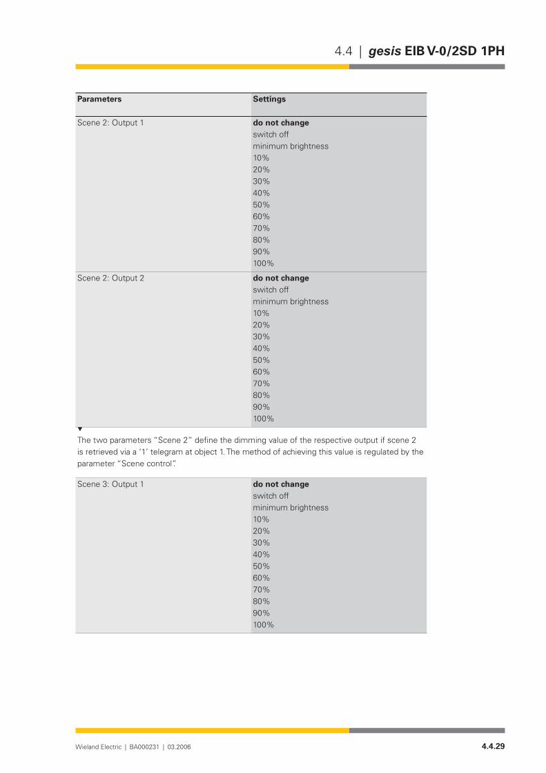
4.4.29Wieland Electric | BA000231 | 03.2006
4.4 | gesis EIB V-0/2SD 1PH
Parameters Settings
Scene 2: Output 1 do not changeswitch offminimum brightness10%20%30%40%50%60%70%80%90%100%
Scene 2: Output 2 do not changeswitch offminimum brightness10%20%30%40%50%60%70%80%90%100%
The two parameters “Scene 2” define the dimming value of the respective output if scene 2 is retrieved via a ‘1’ telegram at object 1. The method of achieving this value is regulated by the parameter “Scene control”.
Scene 3: Output 1 do not changeswitch offminimum brightness10%20%30%40%50%60%70%80%90%100%
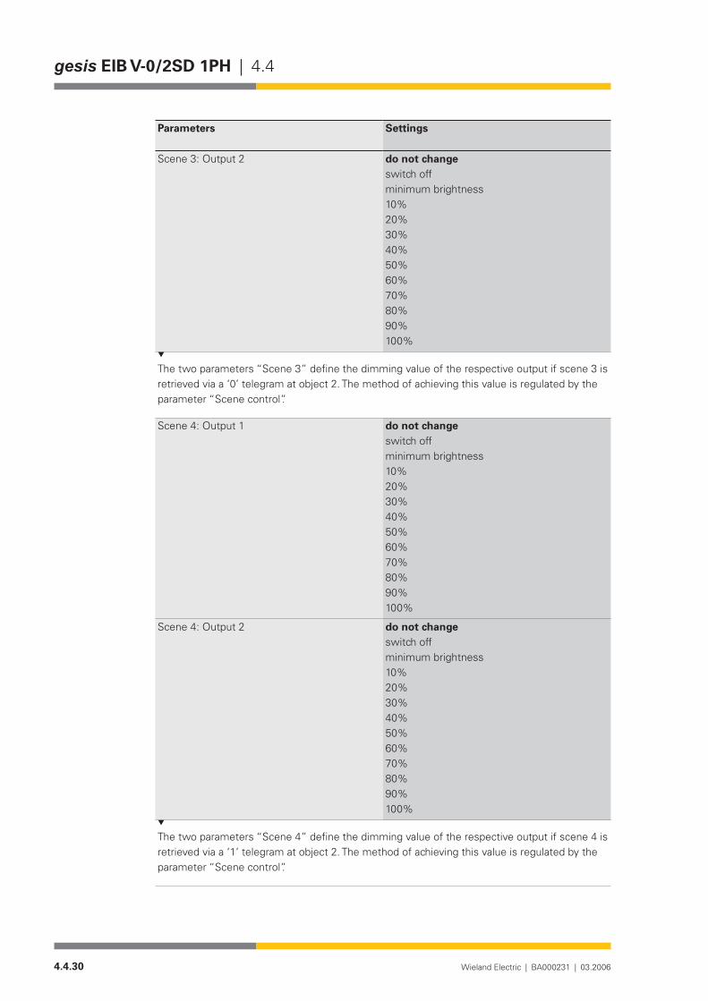
4.4.30 Wieland Electric | BA000231 | 03.2006
gesis EIB V-0/2SD 1PH | 4.4
Parameters Settings
Scene 3: Output 2 do not changeswitch offminimum brightness10%20%30%40%50%60%70%80%90%100%
The two parameters “Scene 3” define the dimming value of the respective output if scene 3 is retrieved via a ‘0’ telegram at object 2. The method of achieving this value is regulated by the parameter “Scene control”.
Scene 4: Output 1 do not changeswitch offminimum brightness10%20%30%40%50%60%70%80%90%100%
Scene 4: Output 2 do not changeswitch offminimum brightness10%20%30%40%50%60%70%80%90%100%
The two parameters “Scene 4” define the dimming value of the respective output if scene 4 is retrieved via a ‘1’ telegram at object 2. The method of achieving this value is regulated by the parameter “Scene control”.
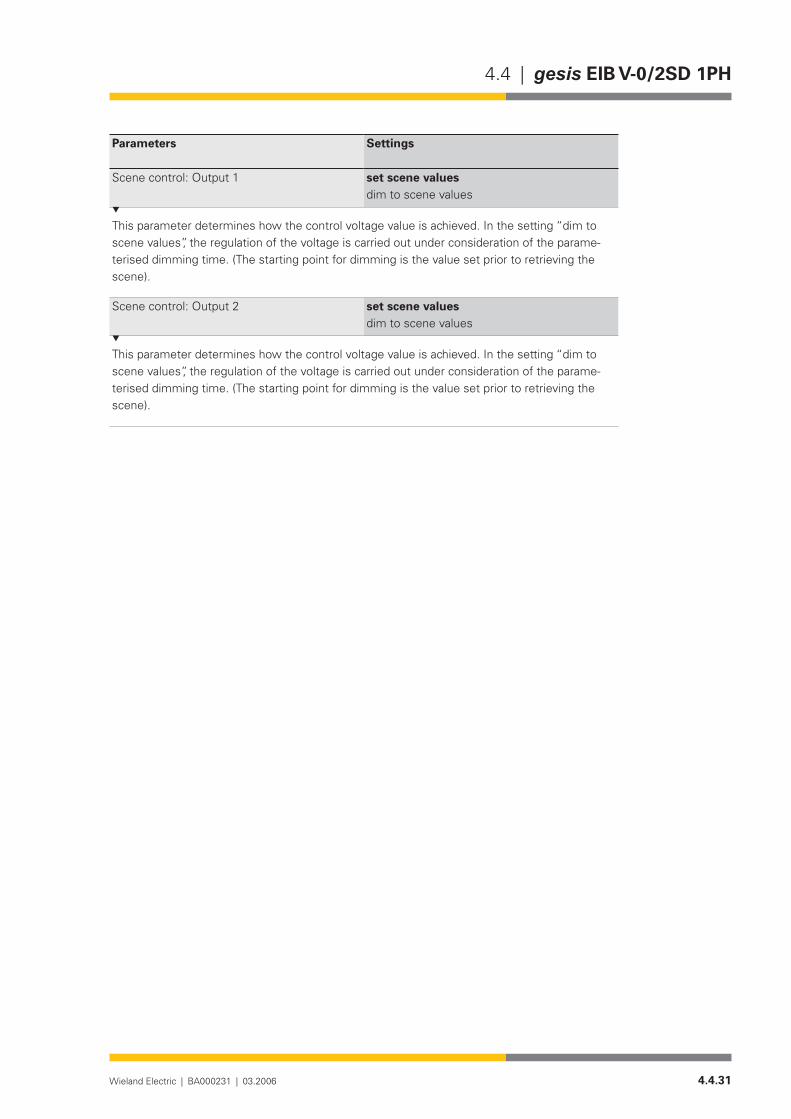
4.4.31Wieland Electric | BA000231 | 03.2006
4.4 | gesis EIB V-0/2SD 1PH
Parameters Settings
Scene control: Output 1 set scene valuesdim to scene values
This parameter determines how the control voltage value is achieved. In the setting “dim to scene values”, the regulation of the voltage is carried out under consideration of the parame-terised dimming time. (The starting point for dimming is the value set prior to retrieving the scene).
Scene control: Output 2 set scene valuesdim to scene values
This parameter determines how the control voltage value is achieved. In the setting “dim to scene values”, the regulation of the voltage is carried out under consideration of the parame-terised dimming time. (The starting point for dimming is the value set prior to retrieving the scene).

4.4.32 Wieland Electric | BA000231 | 03.2006
gesis EIB V-0/2SD 1PH | 4.4

4.5.1Wieland Electric | BA000231 | 03.2006
4.5 | gesis EIB V-0/2W SI
gesis EIB V-0/2W SI
Product description
Designation• Shutter actuator, 2-foldType• gesis EIB V-0/2W SIPart number• 83.020.0211.0Device type• EIB shutter actuator, 2-fold
Non-floating switch outputs 230 V ACDesign• Device with plug-in connections for surface mounting in
enclosed rooms, fixing with two screws Mains connection• 3-phaseETS2 application program• gesis EIB V-0/2W SI 1.0
Function
The shutter actuator gesis EIB V-0/2W SI can control 230 V AC loads (shutter motors, roller blinds, awning, skylights etc.) without dependence on time and set both the height of the shutter and the angle of the louvres.
The actuator receives control commands via the EIB bus which it transmits to the output relays as positioning commands. Two interlocked relays are available per output. They are swit-ched on and off via the bus voltage and can control two independent motors in two directions of rotations. The switch outputs are non-floating. That means that each output is already linked internally with the potentials N, PE and linked with an outer conductor of the mains voltage via a corresponding relay contact.
It is possible to move to any shutter or louvre position when the actuator is in positioning mode. The accuracy of the control is mainly dependent on the motor, gear unit and shutter as the actuator does not receive a status signal regarding the position from the drive.
Drives with electromechanical limit switches (A) or drives with integrated electronics for disconnection at the limit position (B) can be connected to the shutter actuator. In both cases, the period for louvre adjustment must be measured manually and entered via parameters in the application program.
Mixed operation of the named drive types at an output is not permitted.The parameterisation and operation of the device requires application software. It is loaded
into the device using EIB Tool Software (ETS2).
The travel time required to calculate the positions is determined automatically.The reverse voltage of the connected drive must lie within the defined limits (see under
Technical data/Outputs/Reverse voltage of the motor).To define the travel time of the shutter, a reference movement is carried out once automati-
cally. This happens on receipt of the first positioning command if the actuator has been pro-grammed. The measured travel time is synchronised with this reference movement each time the shutter reaches a limit position (upper limit position t=0, lower limit position t=specified travel time). A new reference movement is carried out after each recovery of the bus voltage. It is possible to move immediately to a louvre position after reaching a limit position for the first time.
General description
Drives with elec-tromechanical limit switches
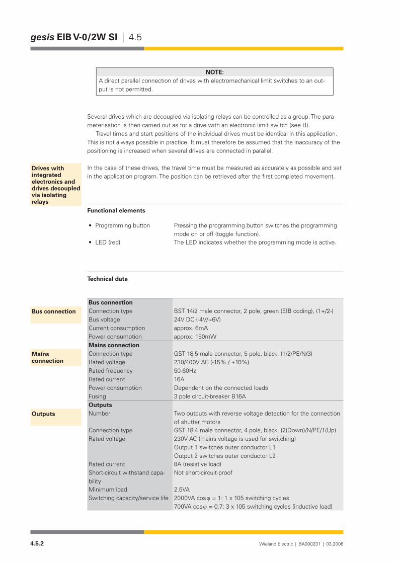
4.5.2 Wieland Electric | BA000231 | 03.2006
gesis EIB V-0/2W SI | 4.5
NOTE:A direct parallel connection of drives with electromechanical limit switches to an out-put is not permitted.
Several drives which are decoupled via isolating relays can be controlled as a group. The para-meterisation is then carried out as for a drive with an electronic limit switch (see B).
Travel times and start positions of the individual drives must be identical in this application. This is not always possible in practice. It must therefore be assumed that the inaccuracy of the positioning is increased when several drives are connected in parallel.
In the case of these drives, the travel time must be measured as accurately as possible and set in the application program. The position can be retrieved after the first completed movement.
Functional elements
Programming button• Pressing the programming button switches the programming mode on or off (toggle function).
LED (red)• The LED indicates whether the programming mode is active.
Technical data
Bus connectionConnection type BST 14i2 male connector, 2 pole, green (EIB coding), (1+/2-)Bus voltage 24V DC (-4V/+6V)Current consumption approx. 6mAPower consumption approx. 150mWMains connectionConnection type GST 18i5 male connector, 5 pole, black, (1/2/PE/N/3)Rated voltage 230/400V AC (-15% / +10%)Rated frequency 50-60HzRated current 16APower consumption Dependent on the connected loadsFusing 3 pole circuit-breaker B16AOutputsNumber Two outputs with reverse voltage detection for the connection
of shutter motorsConnection type GST 18i4 male connector, 4 pole, black, (2(Down)/N/PE/1(Up)Rated voltage 230V AC (mains voltage is used for switching)
Output 1 switches outer conductor L1 Output 2 switches outer conductor L2
Rated current 8A (resistive load)Short-circuit withstand capa-bility
Not short-circuit-proof
Minimum load 2.5VASwitching capacity/service life 2000VA cos ϕ = 1: 1 x 10⁵ switching cycles
700VAcosϕ=0.7:3x10⁵switchingcycles(inductiveload)
Drives with integrated electronics and drives decoupled via isolating relays
Bus connection
Mains connection
Outputs
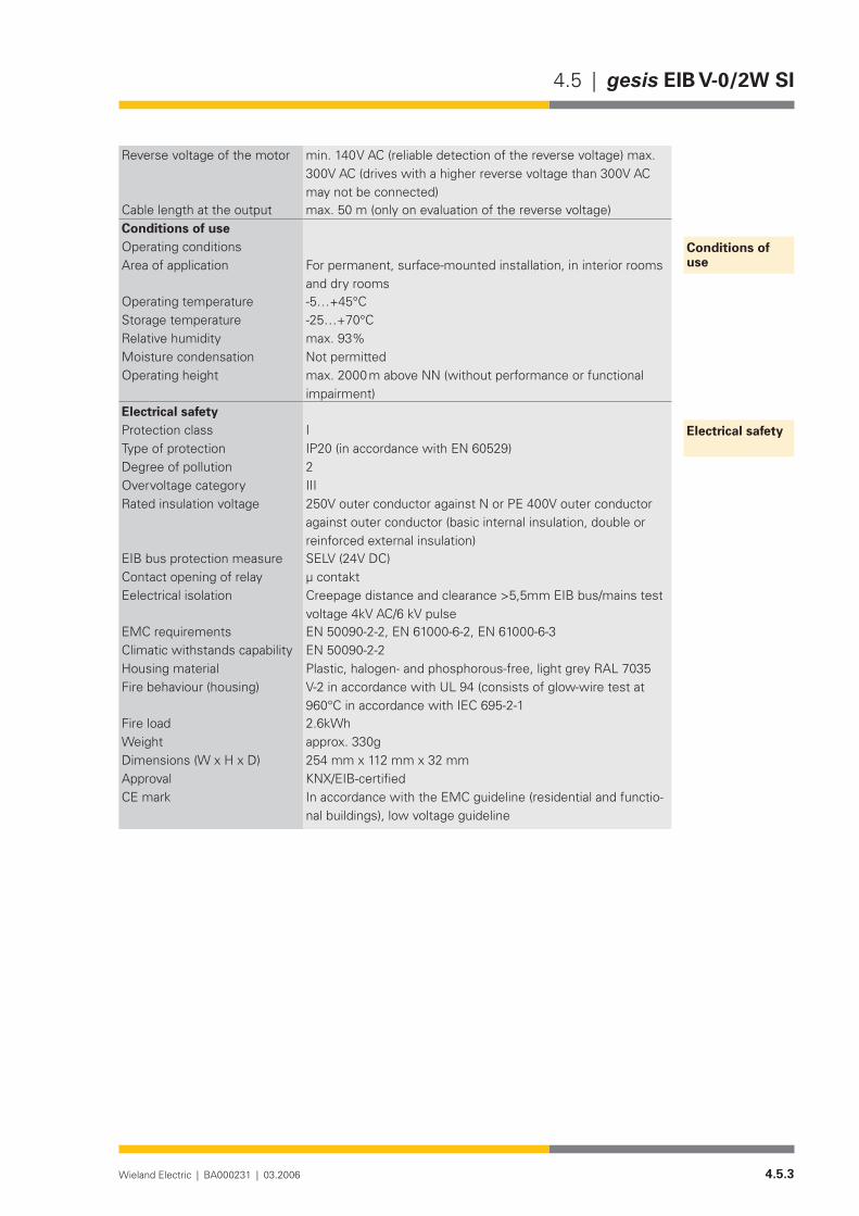
4.5.3Wieland Electric | BA000231 | 03.2006
4.5 | gesis EIB V-0/2W SI
Reverse voltage of the motor min. 140 V AC (reliable detection of the reverse voltage) max. 300V AC (drives with a higher reverse voltage than 300V AC may not be connected)
Cable length at the output max. 50 m (only on evaluation of the reverse voltage)Conditions of useOperating conditionsArea of application For permanent, surface-mounted installation, in interior rooms
and dry roomsOperating temperature -5…+45°CStorage temperature -25…+70°CRelative humidity max. 93%Moisture condensation Not permittedOperating height max. 2000 m above NN (without performance or functional
impairment)Electrical safetyProtection class IType of protection IP20 (in accordance with EN 60529)Degree of pollution 2Overvoltage category IIIRated insulation voltage 250V outer conductor against N or PE 400V outer conductor
against outer conductor (basic internal insulation, double or reinforced external insulation)
EIB bus protection measure SELV (24V DC)Contact opening of relay µ contaktEelectrical isolation Creepage distance and clearance >5,5mm EIB bus/mains test
voltage 4kV AC/6 kV pulseEMC requirements EN 50090-2-2, EN 61000-6-2, EN 61000-6-3 Climatic withstands capability EN 50090-2-2Housing material Plastic,halogen-andphosphorous-free,lightgreyRAL7035Fire behaviour (housing) V-2 in accordance with UL 94 (consists of glow-wire test at
960°CinaccordancewithIEC695-2-1Fire load 2.6kWhWeight approx. 330gDimensions (W x H x D) 254 mm x 112 mm x 32 mmApproval KNX/EIB-certifiedCE mark In accordance with the EMC guideline (residential and functio-
nal buildings), low voltage guideline
Conditions of use
Electrical safety
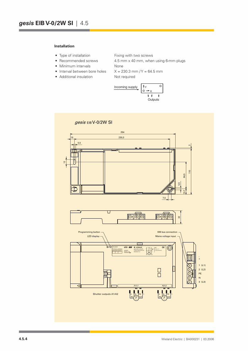
4.5.4 Wieland Electric | BA000231 | 03.2006
gesis EIB V-0/2W SI | 4.5
Installation
Type of installation• Fixing with two screwsRecommended screws• 4.5 mm x 40 mm, when using 6-mm plugsMinimum intervals• NoneInterval between bore holes• X = 230.3 mm / Y = 64.5 mmAdditional insulation• Not required
�
����������������
�������
V-0/2W SIEIB
2
7,5
230,3
12
10
5,5
5,5
64,5
13,7
110
254
gesis
A2/L2A1/L1
2 PEN 1 1N PE2
1~M AufAb Ab Auf
1 (L1)
2 (L2)
PE
N
3 (L3)
-+
Shutter outputs A1/A2
32
1~M
DEVICELINEAREA
PHYSICAL ADDRESS:
PROGRAM
230/400V50/60Hz; 16A 83.020.0211.0
EIB V-0/2W SI2 SHUTTER OUTPUTSgesis
wielandw 230V~
m
8A cos =13A cos =0,4 ind.
N PEA1/A2
M1~ AufAb
Mains voltage input
EIB bus connectionProgramming button
LED display
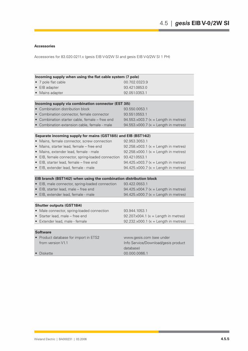
4.5.5Wieland Electric | BA000231 | 03.2006
4.5 | gesis EIB V-0/2W SI
Accessories
Accessories for 83.020.0211.x (gesis EIB V-0/2W SI and gesis EIB V-0/2W SI 1 PH)
Incoming supply when using the flat cable system (7 pole)7poleflatcable• 00.702.0323.9EIB adapter• 93.421.0853.0Mains adapter• 92.051.0353.1
Incoming supply via combination connector (EST 3i5)Combination distribution block• 93.550.0053.1Combination connector, female connector• 93.551.0553.1Combination starter cable, female – free end• 94.553.x003.7(x=Lengthinmetres)Combination extension cable, female - male• 94.553.x000.7(x=Lengthinmetres)
Separate incoming supply for mains (GST18i5) and EIB (BST14i2)Mains, female connector, screw connection• 92.953.3053.1Mains, starter lead, female – free end• 92.258.x003.1 (x = Length in metres)Mains, extender lead, female - male• 92.258.x000.1 (x = Length in metres)EIB, female connector, spring-loaded connection• 93.421.0553.1EIB, starter lead, female – free end• 94.425.x003.7(x=Lengthinmetres)EIB, extender lead, female - male• 94.425.x000.7(x=Lengthinmetres)
EIB branch (BST14i2) when using the combination distribution blockEIB, male connector, spring-loaded connection• 93.422.0553.1EIB, starter lead, male – free end• 94.425.x004.7(x=Lengthinmetres)EIB, extender lead, female - male• 94.425.x000.7(x=Lengthinmetres)
Shutter outputs (GST18i4)Male connector, spring-loaded connection• 93.944.1053.1Starter lead, male – free end• 92.207.x004.1(x=Lengthinmetres)Extender lead, male - female• 92.232.x000.1 (x = Length in metres)
SoftwareProduct database for import in ETS2 •from version V1.1
www.gesis.com (see under Info Service/Download/gesis product database)
Diskette• 00.000.0066.1

4.5.6 Wieland Electric | BA000231 | 03.2006
gesis EIB V-0/2W SI | 4.5

4.5.7Wieland Electric | BA000231 | 03.2006
4.5 | gesis EIB V-0/2W SI
Application program
Program name• gesis EIB V-0/2W SI 1Program version• 1.0Product assignment• gesis EIB V-0/2W SI 83.020.0211.0
gesis EIB V-0/2W SI 1PH 83.020.02211.2Reference source• www.gesis.comProduct description• EIB shutter actuator, 2-fold
Non-floating outputs, all plug-in connections, surface mounting
ETS2 search path• Manufacturer: Wieland Electric GmbH Product family: gesis EIB V Product type: Shutter
Function
The two shutter outputs of the above devices are controlled with the application program.The shutter outputs can be controlled separately. To be able to meet special requirements,
the objects and parameters described in the following section are available.In addition to the up/down and louvre adjustment functions, the shutter actuator can also
position the height of the shutter and the louvre angle. This is either carried out via an 8-bit com-mand for each output or via the retrieval of a stored position. The stored position can be set to a new value via a save request (1-bit command). The shutter is brought into the required position via the “Up/Down” and “Louvres/Stop” commands. The position is stored again with the object “Store position”.
NOTES:(A) Two independent variables define the position: “Position shutter” and “Position •louvres” (louvre angle).(B) A total of 80 group addresses and 80 associations are available. They can be •exchanged for each other.(C) Explanation of terms used for the louvre position•
“closed (down)” Point at which the louvres are closed and the shutter starts the downward movement (corresponds to object value 255)
“open” Point at which the louvres are vertical (corresponds to object value 1)
“closed (up)” Point at which the louvres are closed and the shutter starts the upward movement

4.5.8 Wieland Electric | BA000231 | 03.2006
gesis EIB V-0/2W SI | 4.5
Obj Object name Function Type Flags
0 Safety/Alarm Output 1 1 bit C W T U
The receipt of a ‘1’ telegram triggers the actions set in the parameters in the event of an alarm and disables the output for further operation. The alarm is also activated if the parameterised monitoring period has elapsed without a ‘0’ telegram being received at this object. A ‘0’ tele-gram cancels this alarm and enables operation again.
1 Lock Output 1 1 bit C W T U
The receipt of a ‘1’ telegram can disable different objects. A ‘0’ telegram enables them again. The objects that are disabled depends on the setting in the parameter ‘Lock’. The point in the functional sequence at which the disable function intervenes must be taken from the flow diagram.
2 Up/Down Output 1 1 bit C W T U
A telegram received with the useful information ‘0’ controls the ‘Up’ branch in the default setting. A ‘1’ telegram controls the ‘Down’ branch. The method of operation of the telegram is dependent on parameters and further objects. An overview must be taken from the flow diagram. The parameter description offers further information.
Flow diagram
�����
����
�������
����
���������������
��������������
�������������
��������������������
������������������������
�������
�����������������
��������������������
��������������������
��������������������
��������������������
��������������������
��������������������
�����������������������
�������������
�������������
����������
�����������������������������������������������������������������������������������������������������������������������������������������������������������������������
��������������������������������������������������������������
����������������������������������
���������������������������������
�����������������������������������
�
���������
Description of the objects
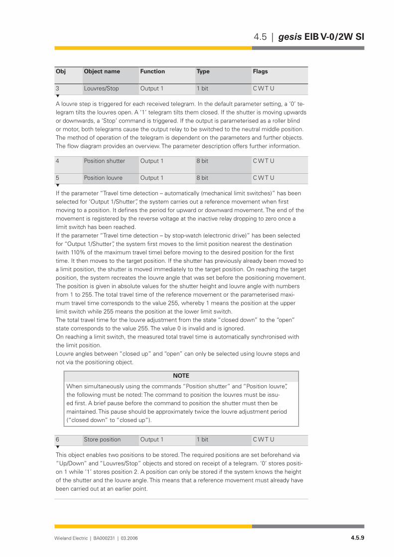
4.5.9Wieland Electric | BA000231 | 03.2006
4.5 | gesis EIB V-0/2W SI
Obj Object name Function Type Flags
3 Louvres/Stop Output 1 1 bit C W T U
A louvre step is triggered for each received telegram. In the default parameter setting, a ‘0’ te-legram tilts the louvres open. A ‘1’ telegram tilts them closed. If the shutter is moving upwards or downwards, a ‘Stop’ command is triggered. If the output is parameterised as a roller blind or motor, both telegrams cause the output relay to be switched to the neutral middle position. The method of operation of the telegram is dependent on the parameters and further objects. The flow diagram provides an overview. The parameter description offers further information.
4 Position shutter Output 1 8 bit C W T U
5 Position louvre Output 1 8 bit C W T U
If the parameter “Travel time detection – automatically (mechanical limit switches)” has been selected for ‘Output 1/Shutter”, the system carries out a reference movement when first moving to a position. It defines the period for upward or downward movement. The end of the movement is registered by the reverse voltage at the inactive relay dropping to zero once a limit switch has been reached.If the parameter “Travel time detection – by stop-watch (electronic drive)” has been selected for “Output 1/Shutter”, the system first moves to the limit position nearest the destination (with 110% of the maximum travel time) before moving to the desired position for the first time. It then moves to the target position. If the shutter has previously already been moved to a limit position, the shutter is moved immediately to the target position. On reaching the target position, the system recreates the louvre angle that was set before the positioning movement.The position is given in absolute values for the shutter height and louvre angle with numbers from 1 to 255. The total travel time of the reference movement or the parameterised maxi-mum travel time corresponds to the value 255, whereby 1 means the position at the upper limit switch while 255 means the position at the lower limit switch.The total travel time for the louvre adjustment from the state “closed down” to the “open” state corresponds to the value 255. The value 0 is invalid and is ignored.On reaching a limit switch, the measured total travel time is automatically synchronised with the limit position.Louvre angles between “closed up” and “open” can only be selected using louvre steps and not via the positioning object.
NOTE
When simultaneously using the commands “Position shutter” and “Position louvre”, the following must be noted: The command to position the louvres must be issu-ed first. A brief pause before the command to position the shutter must then be maintained. This pause should be approximately twice the louvre adjustment period (“closed down” to “closed up”).
6 Store position Output 1 1 bit C W T U
This object enables two positions to be stored. The required positions are set beforehand via “Up/Down” and “Louvres/Stop” objects and stored on receipt of a telegram. ‘0’ stores positi-on 1 while ‘1’ stores position 2. A position can only be stored if the system knows the height of the shutter and the louvre angle. This means that a reference movement must already have been carried out at an earlier point.
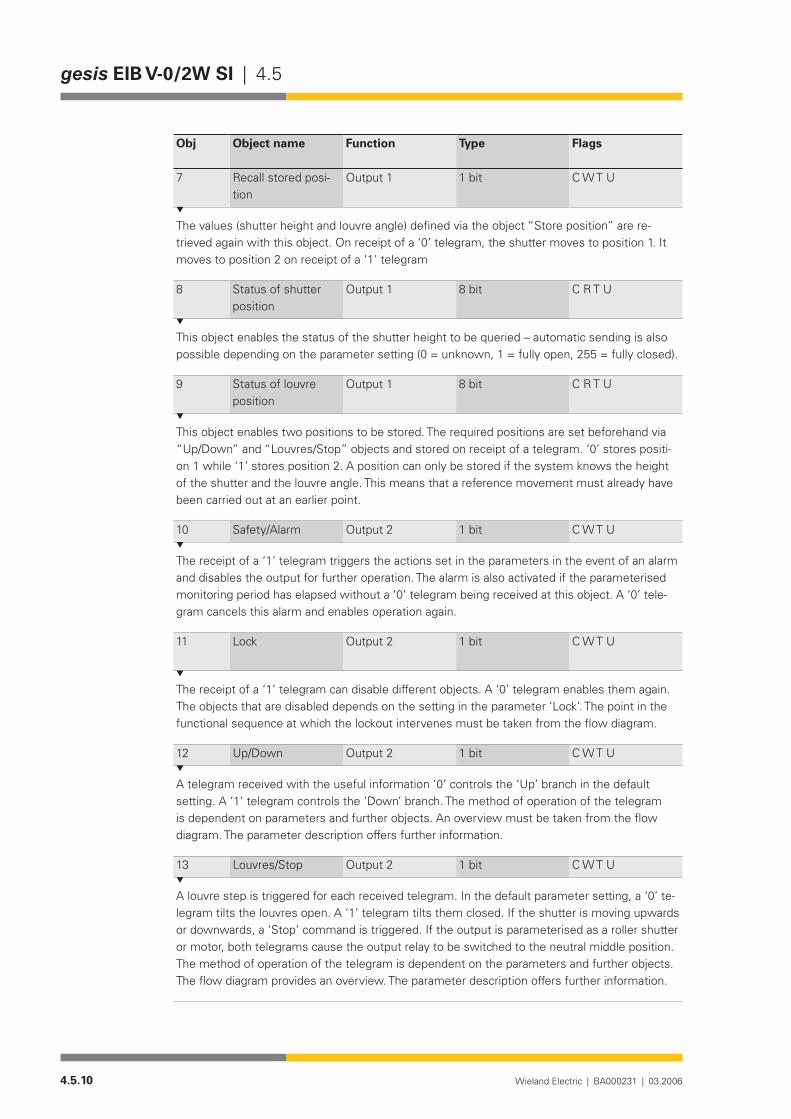
4.5.10 Wieland Electric | BA000231 | 03.2006
gesis EIB V-0/2W SI | 4.5
Obj Object name Function Type Flags
7 Recall stored posi-tion
Output 1 1 bit C W T U
The values (shutter height and louvre angle) defined via the object “Store position” are re-trieved again with this object. On receipt of a ‘0’ telegram, the shutter moves to position 1. It moves to position 2 on receipt of a ‘1’ telegram
8 Status of shutter position
Output 1 8 bit C R T U
This object enables the status of the shutter height to be queried – automatic sending is also possible depending on the parameter setting (0 = unknown, 1 = fully open, 255 = fully closed).
9 Status of louvre position
Output 1 8 bit C R T U
This object enables two positions to be stored. The required positions are set beforehand via “Up/Down” and “Louvres/Stop” objects and stored on receipt of a telegram. ‘0’ stores positi-on 1 while ‘1’ stores position 2. A position can only be stored if the system knows the height of the shutter and the louvre angle. This means that a reference movement must already have been carried out at an earlier point.
10 Safety/Alarm Output 2 1 bit C W T U
The receipt of a ‘1’ telegram triggers the actions set in the parameters in the event of an alarm and disables the output for further operation. The alarm is also activated if the parameterised monitoring period has elapsed without a ‘0’ telegram being received at this object. A ‘0’ tele-gram cancels this alarm and enables operation again.
11 Lock Output 2 1 bit C W T U
The receipt of a ‘1’ telegram can disable different objects. A ‘0’ telegram enables them again. The objects that are disabled depends on the setting in the parameter ‘Lock’. The point in the functional sequence at which the lockout intervenes must be taken from the flow diagram.
12 Up/Down Output 2 1 bit C W T U
A telegram received with the useful information ‘0’ controls the ‘Up’ branch in the default setting. A ‘1’ telegram controls the ‘Down’ branch. The method of operation of the telegram is dependent on parameters and further objects. An overview must be taken from the flow diagram. The parameter description offers further information.
13 Louvres/Stop Output 2 1 bit C W T U
A louvre step is triggered for each received telegram. In the default parameter setting, a ‘0’ te-legram tilts the louvres open. A ‘1’ telegram tilts them closed. If the shutter is moving upwards or downwards, a ‘Stop’ command is triggered. If the output is parameterised as a roller shutter or motor, both telegrams cause the output relay to be switched to the neutral middle position. The method of operation of the telegram is dependent on the parameters and further objects. The flow diagram provides an overview. The parameter description offers further information.

4.5.11Wieland Electric | BA000231 | 03.2006
4.5 | gesis EIB V-0/2W SI
Obj Object name Function Type Flags
14 Position shutter Output 2 8 bit C W T U
15 Position louvre Output 2 8 bit C W T U
If the parameter “Travel time detection – automatically (mechanical limit switches)” has been selected for ‘Output 2/Shutter”, the system carries out a reference movement when first moving to a position. It defines the period for upward or downward movement. The end of the movement is registered by the reverse voltage at the inactive relay dropping to zero once a limit switch has been reached.If the parameter “Travel time detection – by stop-watch (electronic drive)” has been selected for “Output 2/Shutter”, the system first moves to the limit position nearest the destination (with 110% of the maximum travel time) before moving to the desired position for the first time. It then moves to the target position. If the shutter has previously already been moved to a limit position, the shutter is moved immediately to the target position. On reaching the target position, the system recreates the louvre angle that was set before the positioning movement.The position is given in absolute values for the shutter height and louvre angle with numbers from 1 to 255. The total travel time of the reference movement or the parameterised maxi-mum travel time corresponds to the value 255, whereby 1 means the position at the upper limit switch while 255 means the position at the lower limit switch.The total travel time for the louvre adjustment from the state “closed down” to the “open” state corresponds to the value 255. The value 0 is invalid and is ignored.On reaching a limit switch, the measured total travel time is automatically synchronised with the limit position.Louvre angles between “closed up” and “open” can only be selected using louvre steps and not via the positioning object.Caution: When simultaneously using the commands “Position shutter” and “Position louvre”, the following must be noted: The command to position the louvres must be issued first. A brief pause before the command to position the shutter must then be maintained. This pause should be approximately twice the louvre adjustment period (“closed down” to “closed up”).
16 Store position Output 2 1 bit C W T U
This object enables two positions to be stored. The required positions are set beforehand via “Up/Down” and “Louvres/Stop” objects and stored on receipt of a telegram. ‘0’ stores positi-on 1 while ‘1’ stores position 2. A position can only be stored if the system knows the height of the shutter and the louvre angle. This means that a reference movement must already have been carried out at an earlier point.
17 Recall stored posi-tion
Output 2 1 bit C W T U
The values (shutter height and louvre angle) defined via the object “Store position” are re-trieved again with this object. On receipt of a ‘0’ telegram, the shutter moves to position 1. It moves to position 2 on receipt of a ‘1’ telegram.
18 Status of shutter position
Output 2 8 bit C R T U
This object enables the status of the shutter height to be queried – automatic sending is also possible depending on the parameter setting (0 = unknown, 1 = fully open, 255 = fully closed).
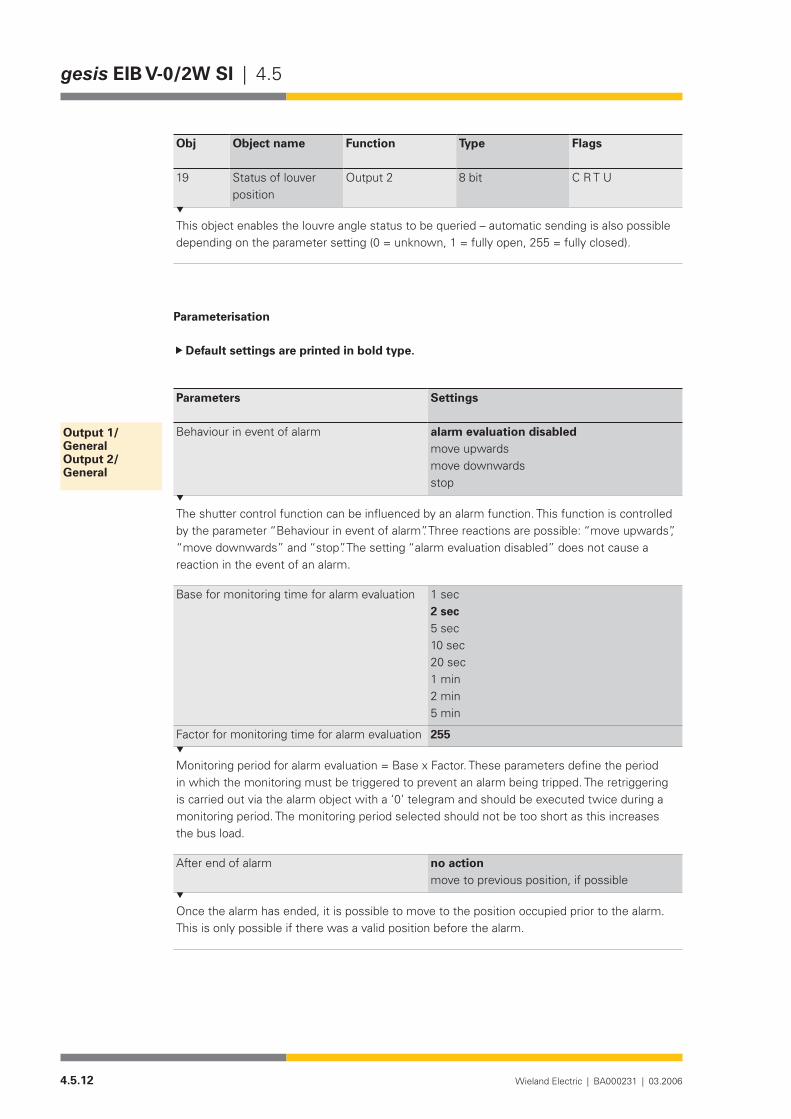
4.5.12 Wieland Electric | BA000231 | 03.2006
gesis EIB V-0/2W SI | 4.5
Obj Object name Function Type Flags
19 Status of louver position
Output 2 8 bit C R T U
This object enables the louvre angle status to be queried – automatic sending is also possible depending on the parameter setting (0 = unknown, 1 = fully open, 255 = fully closed).
Parameterisation
Default settings are printed in bold type.
Parameters Settings
Behaviour in event of alarm alarm evaluation disabledmove upwardsmove downwardsstop
The shutter control function can be influenced by an alarm function. This function is controlled by the parameter “Behaviour in event of alarm”. Three reactions are possible: “move upwards”, “move downwards” and “stop”. The setting “alarm evaluation disabled” does not cause a reaction in the event of an alarm.
Base for monitoring time for alarm evaluation 1 sec2 sec5 sec10 sec20 sec1 min2 min5 min
Factor for monitoring time for alarm evaluation 255
Monitoring period for alarm evaluation = Base x Factor. These parameters define the period in which the monitoring must be triggered to prevent an alarm being tripped. The retriggering is carried out via the alarm object with a ‘0’ telegram and should be executed twice during a monitoring period. The monitoring period selected should not be too short as this increases the bus load.
After end of alarm no actionmove to previous position, if possible
Once the alarm has ended, it is possible to move to the position occupied prior to the alarm. This is only possible if there was a valid position before the alarm.
Output 1/GeneralOutput 2/General

4.5.13Wieland Electric | BA000231 | 03.2006
4.5 | gesis EIB V-0/2W SI
Parameters Settings
Operating mode with travel timecontinuous operation
If the operating mode “with travel time” is selected, the relays are switched to a neutral position once the travel time has elapsed. The output is then de-energised. If an automatic disconnection should not take place once a direction of rotation has been selected, the option “continuous operation” should be set. The output is then only de-energised via a “Louvres/Stop” command.
Direction of rotation normalinverted
If the direction of rotation has been mixed up when installing the motor, the output can be inverted with this parameter. So that all the commands and parameters can be retained, the inversion only takes effect immediately in front of the relays (see functional schematic).
Behaviour on bus voltage failure no actionmove upwardsmove downwardsstop
The set action is carried out in the event of a bus voltage failure. Caution: The relays must switch immediately on bus voltage failure. It is therefore not possible to maintain a pause on reverse.
Lock(the object numbers apply to output 1; for output 2 it is necessary to add 10)
disableaffects object 2affects object 3 affects objects 2 and 3
Note: If the operating mode “continuous operation” is set, the parameter “Lock” is displayed here with all the settings listed above. In the operating mode “with travel time”, this parameter is displayed on the page “Output x/Shutter” or “Output x/Roller blind”. The options are likewise dependent on the selected operating mode. The following description is therefore only valid for the operating mode “continuous operation”. If a ‘1’ is received at the ‘Lock’ object for the respective output, the selected objects in the parameter are disabled (the corresponding output is not modified as a result). On receipt of a ‘0’, these objects are enabled again. The commands that are accepted during the lockout are not carried out once the lockout has been cancelled. The disable function does not have any influence on the alarm function.
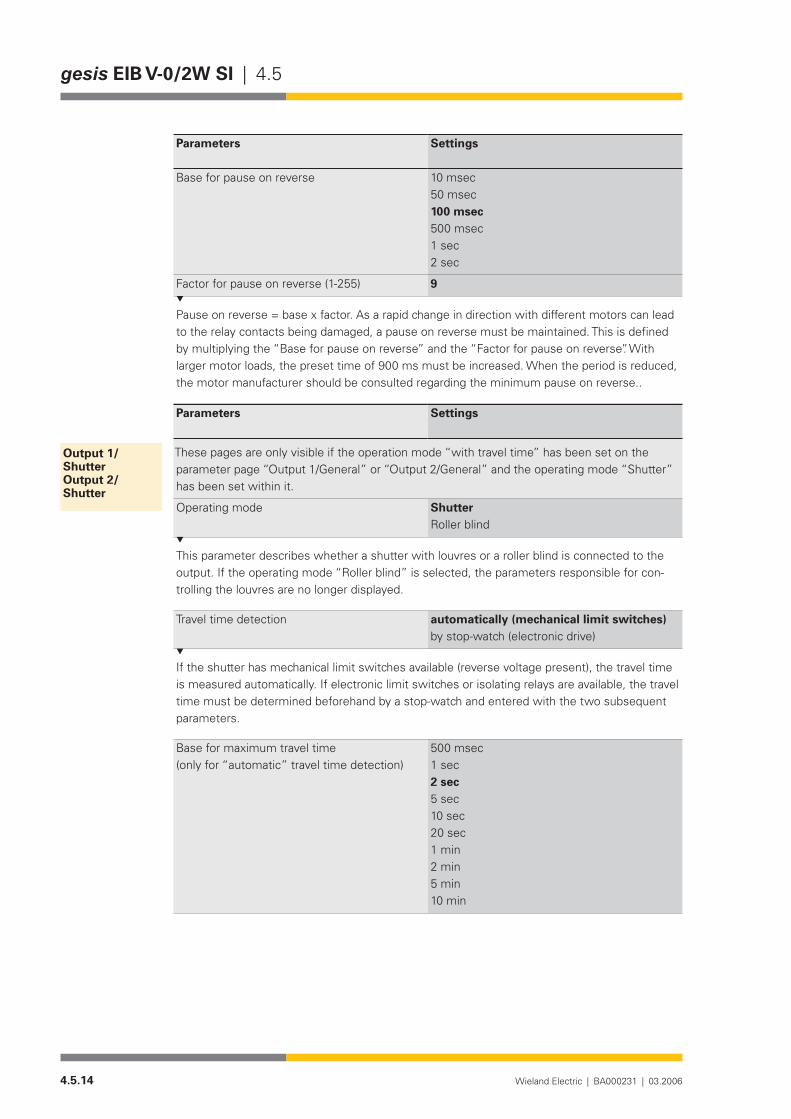
4.5.14 Wieland Electric | BA000231 | 03.2006
gesis EIB V-0/2W SI | 4.5
Parameters Settings
Base for pause on reverse 10 msec50 msec100 msec500 msec1 sec2 sec
Factor for pause on reverse (1-255) 9
Pause on reverse = base x factor. As a rapid change in direction with different motors can lead to the relay contacts being damaged, a pause on reverse must be maintained. This is defined by multiplying the “Base for pause on reverse” and the “Factor for pause on reverse”. With larger motor loads, the preset time of 900 ms must be increased. When the period is reduced, the motor manufacturer should be consulted regarding the minimum pause on reverse..
Parameters Settings
These pages are only visible if the operation mode “with travel time” has been set on the parameter page “Output 1/General” or “Output 2/General” and the operating mode “Shutter” has been set within it.
Operating mode ShutterRoller blind
This parameter describes whether a shutter with louvres or a roller blind is connected to the output. If the operating mode “Roller blind” is selected, the parameters responsible for con-trolling the louvres are no longer displayed.
Travel time detection automatically (mechanical limit switches)by stop-watch (electronic drive)
If the shutter has mechanical limit switches available (reverse voltage present), the travel time is measured automatically. If electronic limit switches or isolating relays are available, the travel time must be determined beforehand by a stop-watch and entered with the two subsequent parameters.
Base for maximum travel time(only for “automatic” travel time detection)
500 msec1 sec2 sec5 sec10 sec20 sec1 min2 min5 min10 min
Output 1/ShutterOutput 2/Shutter

4.5.15Wieland Electric | BA000231 | 03.2006
4.5 | gesis EIB V-0/2W SI
Factor for maximum travel time(only for “automatic” travel time detection)
150
Maximum travel time = “Base for maximum travel time” x “Factor for maximum travel time”If no reference movement has been carried out, the time given above is used as the maximum travel time for downward movement. The period is extended by 10% for upward movement. Once these times have been achieved, the output is de-energised so that the output is not continually live when the limit switches are not detected. As soon as a successful reference movement has been carried out, the time determined by the actuator itself for the correspon-ding output is used as the travel time.
Base for measured travel time(only visible for “Travel time detection by stop-watch”)
500 msec1 sec2 sec5 sec10 sec20 sec1 min2 min5 min10 min
Factor for measured travel time (10-255)(only visible for “Travel time detection by stop-watch”)
60
Measured travel time = “Base for measured travel time” x “Factor for measured travel time”The travel time for the shutter, determined using the stop-watch, is entered with these para-meters. This period is used to determine the height of the shutter (EIS6) for a drive without reversevoltageandfordownwardmovement(EIS7).Thetimeisextendedby10%forupwardmovement(EIS7).
Lock(the object numbers apply to output 1; for output 2 it is necessary to add 10)
disableaffects objects 2 and 3affects objects 4 and 5affectsobjects6and7affectsobjects2,3,6and7affectsobjects2…7
If a ‘1’ is received at the ‘Lock’ object for the respective output, the selected objects in the parameter are disabled (the corresponding output is not modified as a result). On receipt of a ‘0’, these objects are enabled again. The commands that are accepted during the lockout are not carried out once the lockout has been cancelled. The disable function does not have any influence on the alarm function.
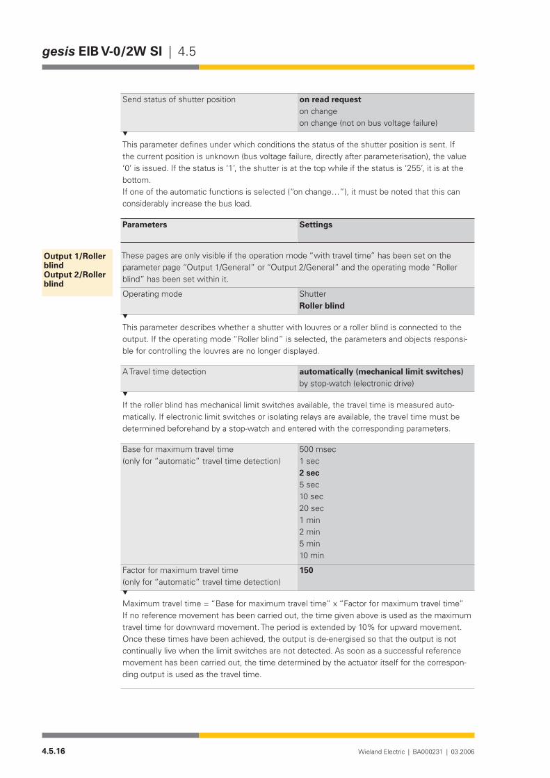
4.5.16 Wieland Electric | BA000231 | 03.2006
gesis EIB V-0/2W SI | 4.5
Send status of shutter position on read requeston changeon change (not on bus voltage failure)
This parameter defines under which conditions the status of the shutter position is sent. If the current position is unknown (bus voltage failure, directly after parameterisation), the value ‘0’ is issued. If the status is ‘1’, the shutter is at the top while if the status is ‘255’, it is at the bottom.Ifoneoftheautomaticfunctionsisselected(“onchange…”),itmustbenotedthatthiscanconsiderably increase the bus load.
Parameters Settings
These pages are only visible if the operation mode “with travel time” has been set on the parameter page “Output 1/General” or “Output 2/General” and the operating mode “Roller blind” has been set within it.
Operating mode ShutterRoller blind
This parameter describes whether a shutter with louvres or a roller blind is connected to the output. If the operating mode “Roller blind” is selected, the parameters and objects responsi-ble for controlling the louvres are no longer displayed.
A Travel time detection automatically (mechanical limit switches)by stop-watch (electronic drive)
If the roller blind has mechanical limit switches available, the travel time is measured auto-matically. If electronic limit switches or isolating relays are available, the travel time must be determined beforehand by a stop-watch and entered with the corresponding parameters.
Base for maximum travel time(only for “automatic” travel time detection)
500 msec1 sec2 sec5 sec10 sec20 sec1 min2 min5 min10 min
Factor for maximum travel time(only for “automatic” travel time detection)
150
Maximum travel time = “Base for maximum travel time” x “Factor for maximum travel time”If no reference movement has been carried out, the time given above is used as the maximum travel time for downward movement. The period is extended by 10% for upward movement. Once these times have been achieved, the output is de-energised so that the output is not continually live when the limit switches are not detected. As soon as a successful reference movement has been carried out, the time determined by the actuator itself for the correspon-ding output is used as the travel time.
Output 1/Roller blindOutput 2/Roller blind
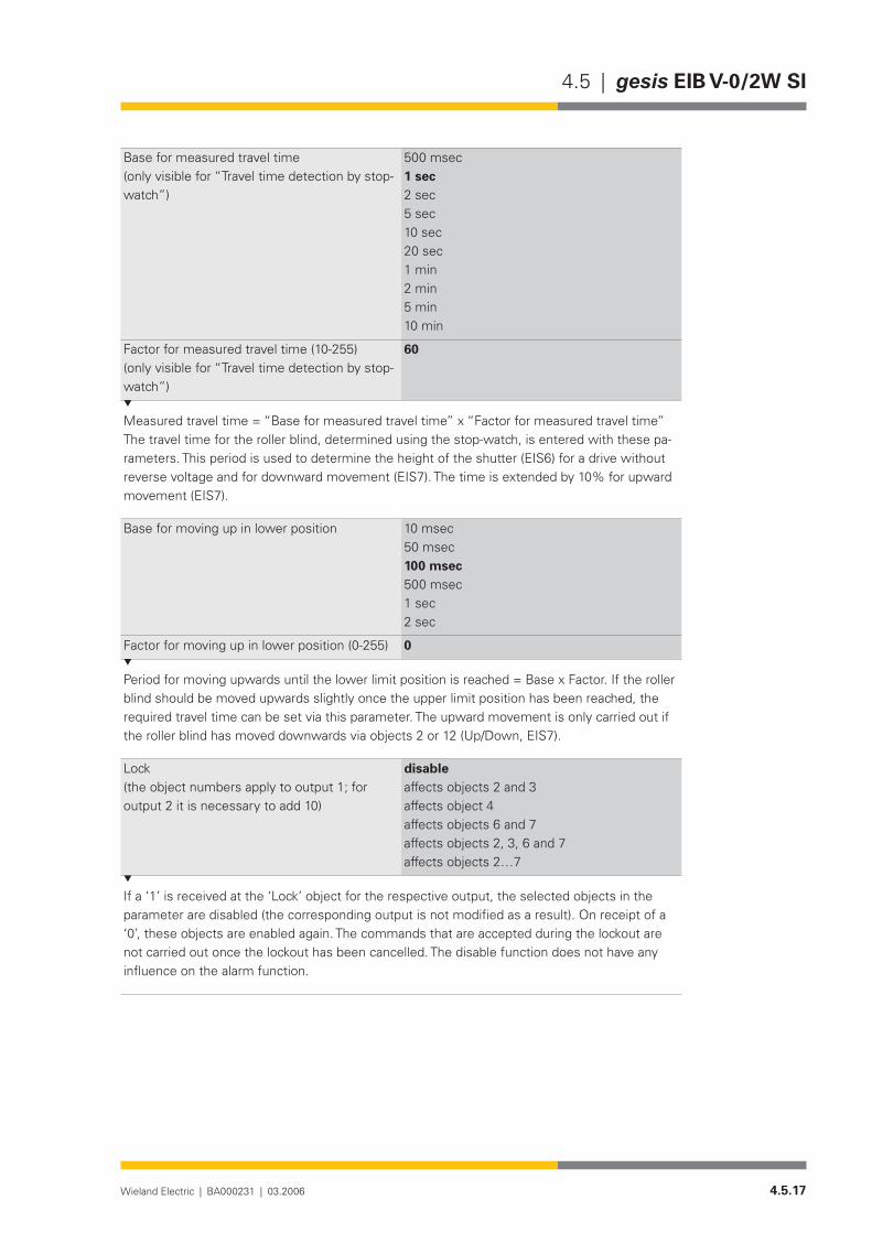
4.5.17Wieland Electric | BA000231 | 03.2006
4.5 | gesis EIB V-0/2W SI
Base for measured travel time(only visible for “Travel time detection by stop-watch”)
500 msec1 sec2 sec5 sec10 sec20 sec1 min2 min5 min10 min
Factor for measured travel time (10-255)(only visible for “Travel time detection by stop-watch”)
60
Measured travel time = “Base for measured travel time” x “Factor for measured travel time”The travel time for the roller blind, determined using the stop-watch, is entered with these pa-rameters. This period is used to determine the height of the shutter (EIS6) for a drive without reversevoltageandfordownwardmovement(EIS7).Thetimeisextendedby10%forupwardmovement(EIS7).
Base for moving up in lower position 10 msec50 msec100 msec500 msec1 sec2 sec
Factor for moving up in lower position (0-255) 0
Period for moving upwards until the lower limit position is reached = Base x Factor. If the roller blind should be moved upwards slightly once the upper limit position has been reached, the required travel time can be set via this parameter. The upward movement is only carried out if therollerblindhasmoveddownwardsviaobjects2or12(Up/Down,EIS7).
Lock(the object numbers apply to output 1; for output 2 it is necessary to add 10)
disableaffects objects 2 and 3affects object 4 affectsobjects6and7affectsobjects2,3,6and7affectsobjects2…7
If a ‘1’ is received at the ‘Lock’ object for the respective output, the selected objects in the parameter are disabled (the corresponding output is not modified as a result). On receipt of a ‘0’, these objects are enabled again. The commands that are accepted during the lockout are not carried out once the lockout has been cancelled. The disable function does not have any influence on the alarm function.

4.5.18 Wieland Electric | BA000231 | 03.2006
gesis EIB V-0/2W SI | 4.5
Send status of shutter position on read requeston changeon change (not on bus voltage failure)
This parameter defines under which conditions the status of the shutter position is sent. If the current position is unknown (bus voltage failure, directly after parameterisation), the value ‘0’ is issued. If the status is ‘1’, the shutter is at the top while if the status is ‘255’, it is at the bottom.Ifoneoftheautomaticfunctionsisselected(“onchange…”),itmustbenotedthatthiscanconsiderably increase the bus load.
Parameters Settings
These pages are only visible if the operation mode “with travel time” has been set on the parameter page “Output 1/General” or “Output 2/General” and the operating mode “Shutter” has been set on the parameter page “Output 1/Shutter” or “Output 2/Shutter”.
Number of steps from louvre closed (down) to louvre open (horizontal)
5
This parameter defines how many steps the shutter carries out until the louvres are rotated between the positions “closed (down)” and “open”. The steps which are required from “open” to “closed (up)” may not be taken into account here. A step is executed if the command is carriedoutviatheobjects3or13(Louvres/Stop,EIS7).
Base for louvre adjustment from closed (down) to open (horizontal)
10 msec50 msec100 msec500 msec1 sec2 sec
Factor for louvre adjustment from closed (down) to open (horizontal) (10-255)
50
Period for louvre adjustment = Base x Factor. This parameter describes the measured period from “closed (down)” to “open”. This input is important for the positioning and time calculation of the louvre angle and shutter height (when the louvres are controlled via the objects 5 or 15 (Position louvres, EIS6)).
Base for total louvre adjustment from closed (down) to closed (up)
10 msec50 msec100 msec500 msec1 sec2 sec
Output 1/louvreOutput 2/louvre

4.5.19Wieland Electric | BA000231 | 03.2006
4.5 | gesis EIB V-0/2W SI
Factor for total louvre adjustment from closed (down) to closed (up) (10-255)
100
Period for louvre adjustment = Base x Factor. This parameter describes the measured period from “closed (down)” to “closed (up)”. This corresponds to the period which is required for rotating the louvres when changing from a pure downward movement to a pure upward mo-vement. For shutters which move upwards with their louvres opened, this period is identical to the period from “closed (down)” to “open”.
Base for fanning out in lower position 10 msec50 msec100 msec500 msec1 sec2 sec
Factor for fanning out in lower position (0-255)
0
Period for fanning out on reaching the lower limit position = “Base for fanning out in lower position” x “Factor for fanning out in lower position”If the shutter should be moved upwards slightly once the upper limit position has been rea-ched (fanning out), the required travel time can be set via this parameter. The upward move-ment is only carried out if the shutter has moved downwards via objects 2 or 12 (Up/Down, EIS7).
Send status of louvre position on read requeston changeon change (not on bus voltage recovery)
This parameter defines under which conditions the status of the louvre position is sent. If the current position is unknown (after bus voltage recovery or directly after parameterisa-tion), the value ‘0’ is issued. If the status of the louvre angle is ‘1’, the louvres are opened (horizontal) while if the status is ‘255’, the louvres are “closed (down)”. If the louvre position is between “open” and “closed (up)”, the value “1” is always issued.Ifoneoftheautomaticfunctionsisselected(“onchange…”),itmustbenotedthatthiscanconsiderably increase the bus load.
Base for fanning out in lower position 10 msec50 msec100 msec500 msec1 sec2 sec
Factor for fanning out in lower position (0-255)
0
Period for fanning out on reaching the lower limit position = “Base for fanning out in lower position” x “Factor for fanning out in lower position”The fanning out is only carried out in uninterrupted downward movement and immediately on reaching the lower limit switch.If an alarm triggers this downward movement, the fanning out is ignored.
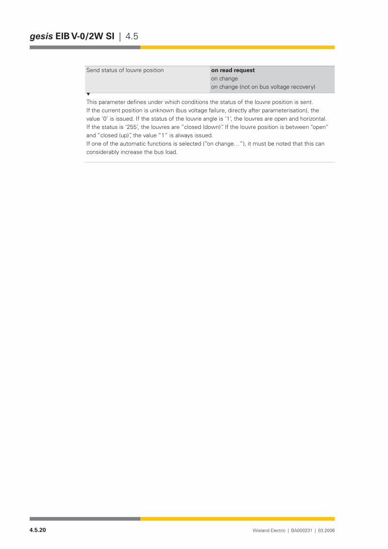
4.5.20 Wieland Electric | BA000231 | 03.2006
gesis EIB V-0/2W SI | 4.5
Send status of louvre position on read requeston changeon change (not on bus voltage recovery)
This parameter defines under which conditions the status of the louvre position is sent. If the current position is unknown (bus voltage failure, directly after parameterisation), the value ‘0’ is issued. If the status of the louvre angle is ‘1’, the louvres are open and horizontal. If the status is ‘255’, the louvres are “closed (down)”. If the louvre position is between “open” and “closed (up)”, the value “1” is always issued.Ifoneoftheautomaticfunctionsisselected(“onchange…”),itmustbenotedthatthiscanconsiderably increase the bus load.

4.5.21Wieland Electric | BA000231 | 03.2006
4.5 | gesis EIB V-0/2W SI 1PH

4.5.22 Wieland Electric | BA000231 | 03.2006
gesis EIB V-0/2W SI 1PH | 4.5

4.5.23Wieland Electric | BA000231 | 03.2006
4.5 | gesis EIB V-0/2W SI 1PH
gesis EIB V-0/2W SI 1PH
Product description
Designation• Shutter actuator, 2-foldType• gesis EIB V-0/2W SI 1PHPart number• 83.020.0211.2Device type• EIB shutter actuator, 2-fold
Non-floating switch outputs 230 V ACDesign• Device with plug-in connections for surface mounting in enc-
losed rooms, fixing with two screwsMains connection• 1-phase (on PIN 2 of the supply connector)ETS2 -application program• gesis EIB V-0/2W SI 1.0
Function
The shutter actuator gesis EIB V-0/2W SI 1PH can control 230 V AC loads (shutter motors, roller blinds, awning, skylights etc.) without dependence on time (only up/down/stop/louvre adjust-ment) and set both the height of the shutter and the angle of the louvres.
The actuator receives control commands via the EIB bus which it transmits to the output relays as positioning commands. Two interlocked relays are available per output. They are swit-ched on and off via the bus voltage and can control two independent motors in two directions of rotations. The switch outputs are non-floating. That means that each output is already linked internally with the potentials N, PE and linked with an outer conductor of the mains voltage via a corresponding relay contact.
It is possible to move to any shutter or louvre position when the actuator is in positioning mode. The accuracy of the control is mainly dependent on the motor, gear unit and shutter as the actuator does not receive a status signal regarding the position from the drive. Drives with electromechanical limit switches (A) or drives with integrated electronics for disconnection at the limit position (B) can be connected to the shutter actuator. In both cases, the period for louvre adjustment must be measured manually and entered via parameters in the application program.
Mixed operation of the named drive types at an output is not permitted.The parameterisation and operation of the device requires application software. It is loaded
into the device using EIB Tool Software (ETS2).
The travel time required to calculate the positions is determined automatically.The reverse voltage of the connected drive must lie within the defined limits (see under
Technical data/Outputs/Reverse voltage of the motor).To define the travel time of the shutter, a reference movement is carried out once automati-
cally. This happens on receipt of the first positioning command if the actuator has been pro-grammed. The measured travel time is synchronised with this reference movement each time the shutter reaches a limit position (upper limit position t=0, lower limit position t=specified travel time). A new reference movement is carried out after each recovery of the bus voltage. It is possible to move immediately to a louvre position after reaching a limit position for the first time.
General description
Drives with elec-tromechanical limit switches

4.5.24 Wieland Electric | BA000231 | 03.2006
gesis EIB V-0/2W SI 1PH | 4.5
NOTE:A direct parallel connection of drives with electromechanical limit switches to an out-put is not permitted.
Several drives which are decoupled via isolating relays can be controlled as a group. The para-meterisation is then carried out as for a drive with an electronic limit switch (see B).
Travel times and start positions of the individual drives must be identical in this application. This is not always possible in practice. It must therefore be assumed that the inaccuracy of the positioning is increased when several drives are connected in parallel.
In the case of these drives, the travel time must be measured as accurately as possible and set in the application program. The position can be retrieved after the first completed movement.
Functional elements
Programming button• Pressing the programming button switches the programming mode on or off (toggle function).
LED (red)• The LED indicates whether the programming mode is active.
Technical data
Bus connectionConnection type BST 14i2 male connector, 2 pole, green (EIB coding), (1+/2-)Bus voltage 24 V DC (-4V/+6V)Current consumption approx. 6 mAPower consumption approx. 150 mWMains connection
Caution: Only PIN 2 of the connector is inserted in the device
Connection type GST 18i5 male connector, 5 pole, black, (1/2/PE/N/3)Rated voltage 230 V AC (-15%/+10%)Rated frequency 50-60 HzRated current 16 APower consumption Dependent on the connected loadsFusing Circuit-breaker B16A OutputsNumber Two outputs with reverse voltage detection for the connection
of shutter motorsConnection type GST 18i4 male connector, 4 pole, black, (2(Down)/N/PE/1(Up)Rated voltage 230V ACRated current 8 A (resistive load)Short-circuit withstand capability
Not short-circuit-proof
Minimum load 2.5 VASwitching capacity/ service life 2000 VA cos ϕ = 1: 105 switching cycles
700VAcosϕ=0.7:3⋅ 105 switching cycles (inductive load)
Drives with integrated electronics and drives decoupled via isolating relays
Bus connection
Mains connection
Outputs
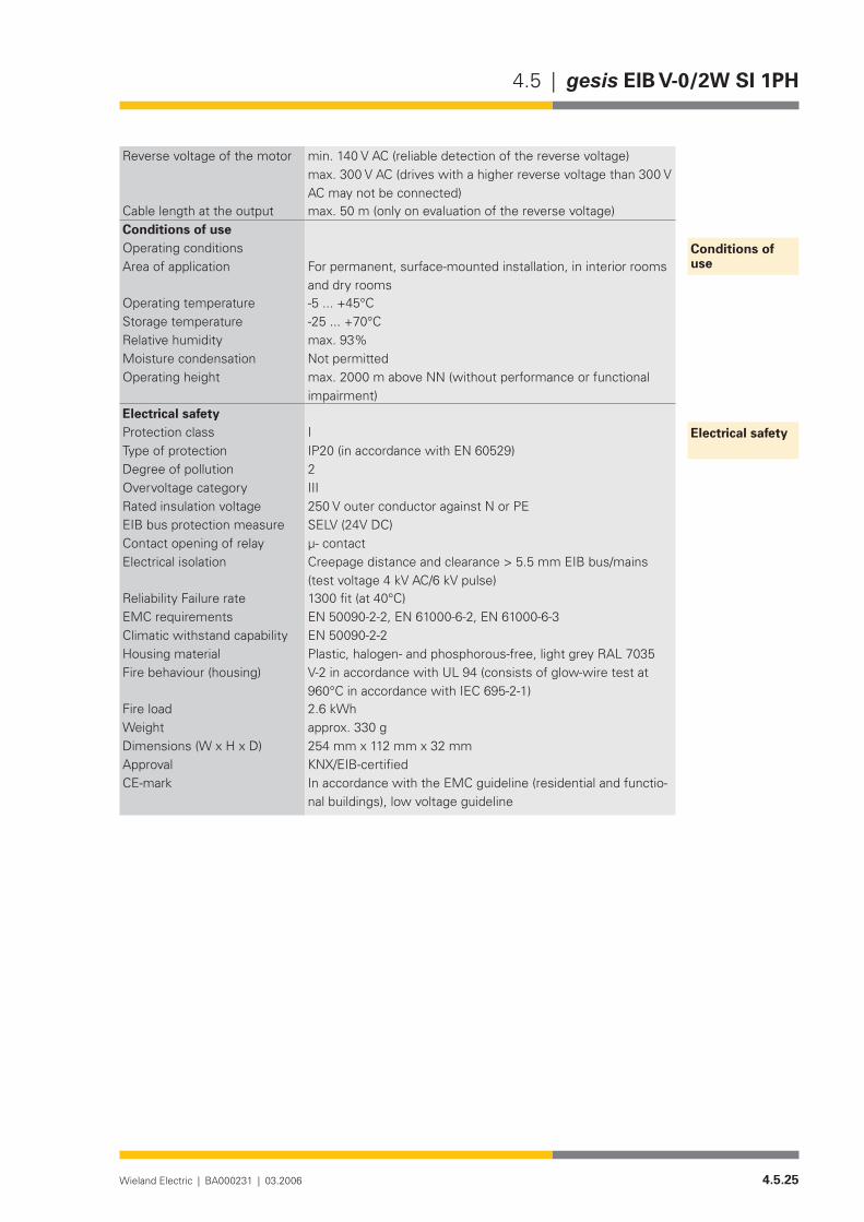
4.5.25Wieland Electric | BA000231 | 03.2006
4.5 | gesis EIB V-0/2W SI 1PH
Reverse voltage of the motor min. 140 V AC (reliable detection of the reverse voltage) max. 300 V AC (drives with a higher reverse voltage than 300 V AC may not be connected)
Cable length at the output max. 50 m (only on evaluation of the reverse voltage)Conditions of useOperating conditionsArea of application For permanent, surface-mounted installation, in interior rooms
and dry roomsOperating temperature -5...+45°CStorage temperature -25...+70°CRelative humidity max. 93%Moisture condensation Not permittedOperating height max. 2000 m above NN (without performance or functional
impairment)Electrical safetyProtection class IType of protection IP20 (in accordance with EN 60529)Degree of pollution 2Overvoltage category IIIRated insulation voltage 250 V outer conductor against N or PEEIB bus protection measure SELV (24V DC)Contact opening of relay µ- contactElectrical isolation Creepage distance and clearance > 5.5 mm EIB bus/mains
(test voltage 4 kV AC/6 kV pulse)Reliability Failure rate 1300fit(at40°C)EMC requirements EN 50090-2-2, EN 61000-6-2, EN 61000-6-3 Climatic withstand capability EN 50090-2-2Housing material Plastic,halogen-andphosphorous-free,lightgreyRAL7035Fire behaviour (housing) V-2 in accordance with UL 94 (consists of glow-wire test at
960°CinaccordancewithIEC695-2-1)Fire load 2.6 kWhWeight approx. 330 gDimensions (W x H x D) 254 mm x 112 mm x 32 mmApproval KNX/EIB-certifiedCE-mark In accordance with the EMC guideline (residential and functio-
nal buildings), low voltage guideline
Conditions of use
Electrical safety

4.5.26 Wieland Electric | BA000231 | 03.2006
gesis EIB V-0/2W SI 1PH | 4.5
Installation
Type of installation• Fixing with two screwsRecommended screws • 4.5 mm x 40 mm, when using 6 mm plugsMinimum intervals• NoneInterval between bore holes • X = 230.3 mm/Y = 64.5 mmAdditional insulation • Not required
�
����������������
�������
254
110
13,7
64,5
5,5
5,5
10
12
230,3
7,5
2
EIB V-0/2W SI 1PHgesis
32
A2A1
Shutter outputs A1/A2AufAbAb AufM
1~
2 PEN 11N PE2M1~
2 (L)
PE
N
-+
DEVICELINEAREA
PHYSICAL ADDRESS:
PROGRAM
230V50/60Hz; 16A 83.020.0211.2
EIB V-0/2W SI 1PH2 SHUTTER OUTPUTSgesis
wielandw 230V~
m
8A cos =13A cos =0,4 ind.
N PEA1/A2
M1~ AufAb
Mains voltage input
EIB bus connectionProgramming button
LED display
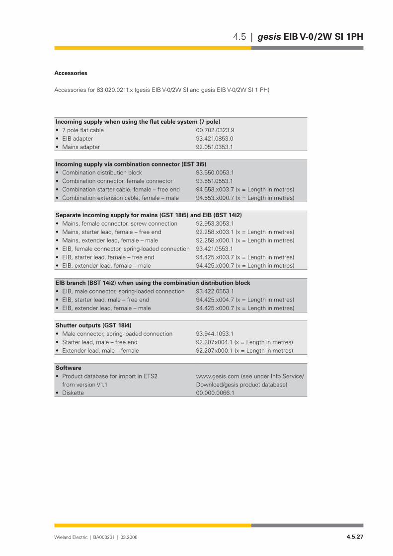
4.5.27Wieland Electric | BA000231 | 03.2006
4.5 | gesis EIB V-0/2W SI 1PH
Accessories
Accessories for 83.020.0211.x (gesis EIB V-0/2W SI and gesis EIB V-0/2W SI 1 PH)
Incoming supply when using the flat cable system (7 pole)7poleflatcable• 00.702.0323.9EIB adapter• 93.421.0853.0Mains adapter• 92.051.0353.1
Incoming supply via combination connector (EST 3i5)Combination distribution block• 93.550.0053.1Combination connector, female connector• 93.551.0553.1Combination starter cable, female – free end• 94.553.x003.7(x=Lengthinmetres)Combination extension cable, female – male• 94.553.x000.7(x=Lengthinmetres)
Separate incoming supply for mains (GST 18i5) and EIB (BST 14i2)Mains, female connector, screw connection• 92.953.3053.1Mains, starter lead, female – free end• 92.258.x003.1 (x = Length in metres)Mains, extender lead, female – male• 92.258.x000.1 (x = Length in metres)EIB, female connector, spring-loaded connection• 93.421.0553.1EIB, starter lead, female – free end• 94.425.x003.7(x=Lengthinmetres)EIB, extender lead, female – male• 94.425.x000.7(x=Lengthinmetres)
EIB branch (BST 14i2) when using the combination distribution blockEIB, male connector, spring-loaded connection• 93.422.0553.1EIB, starter lead, male – free end• 94.425.x004.7(x=Lengthinmetres)EIB, extender lead, female – male• 94.425.x000.7(x=Lengthinmetres)
Shutter outputs (GST 18i4)Male connector, spring-loaded connection• 93.944.1053.1Starter lead, male – free end• 92.207.x004.1(x=Lengthinmetres)Extender lead, male – female• 92.207.x000.1(x=Lengthinmetres)
SoftwareProduct database for import in ETS2 •from version V1.1
www.gesis.com (see under Info Service/Download/gesis product database)
Diskette • 00.000.0066.1

4.5.28 Wieland Electric | BA000231 | 03.2006
gesis EIB V-0/2W SI 1PH | 4.5
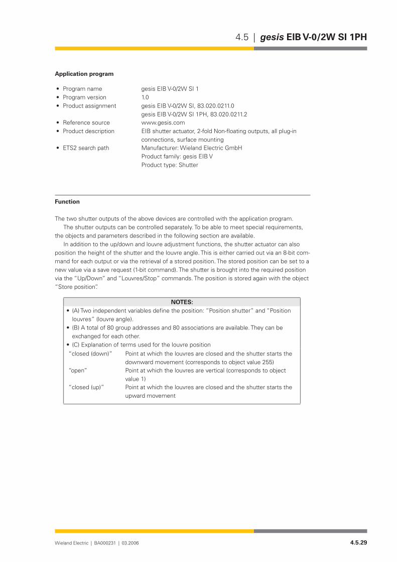
4.5.29Wieland Electric | BA000231 | 03.2006
4.5 | gesis EIB V-0/2W SI 1PH
Application program
Program name• gesis EIB V-0/2W SI 1Program version• 1.0Product assignment• gesis EIB V-0/2W SI, 83.020.0211.0
gesis EIB V-0/2W SI 1PH, 83.020.0211.2Reference source• www.gesis.com Product description • EIB shutter actuator, 2-fold Non-floating outputs, all plug-in
connections, surface mounting ETS2 search path• Manufacturer: Wieland Electric GmbH
Product family: gesis EIB V Product type: Shutter
Function
The two shutter outputs of the above devices are controlled with the application program.The shutter outputs can be controlled separately. To be able to meet special requirements,
the objects and parameters described in the following section are available.In addition to the up/down and louvre adjustment functions, the shutter actuator can also
position the height of the shutter and the louvre angle. This is either carried out via an 8-bit com-mand for each output or via the retrieval of a stored position. The stored position can be set to a new value via a save request (1-bit command). The shutter is brought into the required position via the “Up/Down” and “Louvres/Stop” commands. The position is stored again with the object “Store position”.
NOTES:(A) Two independent variables define the position: “Position shutter” and “Position •louvres” (louvre angle).(B) A total of 80 group addresses and 80 associations are available. They can be •exchanged for each other.(C) Explanation of terms used for the louvre position•
“closed (down)” Point at which the louvres are closed and the shutter starts the downward movement (corresponds to object value 255)
“open” Point at which the louvres are vertical (corresponds to object value 1)
“closed (up)” Point at which the louvres are closed and the shutter starts the upward movement

4.5.30 Wieland Electric | BA000231 | 03.2006
gesis EIB V-0/2W SI 1PH | 4.5
Obj Object name Function Type Flags
0 Safety/Alarm Output 1 1 bit C W T U
The receipt of a ‘1’ telegram triggers the actions set in the parameters in the event of an alarm and disables the output for further operation. The alarm is also activated if the parameterised monitoring period has elapsed without a ‘0’ telegram being received at this object. A ‘0’ tele-gram cancels this alarm and enables operation again.
1 Lock Output 1 1 bit C W T U
The receipt of a ‘1’ telegram can disable different objects. A ‘0’ telegram enables them again. The objects that are disabled depends on the setting in the parameter ‘Lock’. The point in the functional sequence at which the disable function intervenes must be taken from the flow diagram.
2 Up/Down Output 1 1 bit C W T U
A telegram received with the useful information ‘0’ controls the ‘Up’ branch in the default setting. A ‘1’ telegram controls the ‘Down’ branch. The method of operation of the telegram is dependent on parameters and further objects. An overview must be taken from the flow diagram. The parameter description offers further information.
Flow diagram
�����
����
�������
����
���������������
��������������
�������������
��������������������
������������������������
�������
�����������������
��������������������
��������������������
��������������������
��������������������
��������������������
��������������������
�����������������������
�������������
�������������
����������
�����������������������������������������������������������������������������������������������������������������������������������������������������������������������
��������������������������������������������������������������
����������������������������������
���������������������������������
�����������������������������������
�
���������
Description of the objects

4.5.31Wieland Electric | BA000231 | 03.2006
4.5 | gesis EIB V-0/2W SI 1PH
Obj Object name Function Type Flags
3 Louvres/Stop Output 1 1 bit C W T U
A louvre step is triggered for each received telegram. In the default parameter setting, a ‘0’ te-legram tilts the louvres open. A ‘1’ telegram tilts them closed. If the shutter is moving upwards or downwards, a ‘Stop’ command is triggered. If the output is parameterised as a roller blind or motor, both telegrams cause the output relay to be switched to the neutral middle position. The method of operation of the telegram is dependent on the parameters and further objects. The flow diagram provides an overview. The parameter description offers further information.
4 Position shutter Output 1 8 bit C W T U
5 Position louvre Output 1 8 bit C W T U
If the parameter “Travel time detection – automatically (mechanical limit switches)” has been selected for ‘Output 1/Shutter”, the system carries out a reference movement when first moving to a position. It defines the period for upward or downward movement. The end of the movement is registered by the reverse voltage at the inactive relay dropping to zero once a limit switch has been reached.If the parameter “Travel time detection – by stop-watch (electronic drive)” has been selected for “Output 1/Shutter”, the system first moves to the limit position nearest the destination (with 110% of the maximum travel time) before moving to the desired position for the first time. It then moves to the target position. If the shutter has previously already been moved to a limit position, the shutter is moved immediately to the target position. On reaching the target position, the system recreates the louvre angle that was set before the positioning movement.The position is given in absolute values for the shutter height and louvre angle with numbers from 1 to 255. The total travel time of the reference movement or the parameterised maxi-mum travel time corresponds to the value 255, whereby 1 means the position at the upper limit switch while 255 means the position at the lower limit switch.The total travel time for the louvre adjustment from the state “closed down” to the “open” state corresponds to the value 255. The value 0 is invalid and is ignored.On reaching a limit switch, the measured total travel time is automatically synchronised with the limit position.Louvre angles between “closed up” and “open” can only be selected using louvre steps and not via the positioning object.Caution: When simultaneously using the commands “Position shutter” and “Position louvre”, the following must be noted: The command to position the louvres must be issued first. A brief pause before the command to position the shutter must then be maintained. This pause should be approximately twice the louvre adjustment period (“closed down” to “closed up”).
6 Store position Output 1 1 bit C W T U
This object enables two positions to be stored. The required positions are set beforehand via “Up/Down” and “Louvres/Stop” objects and stored on receipt of a telegram. ‘0’ stores positi-on 1 while ‘1’ stores position 2. A position can only be stored if the system knows the height of the shutter and the louvre angle. This means that a reference movement must already have been carried out at an earlier point.
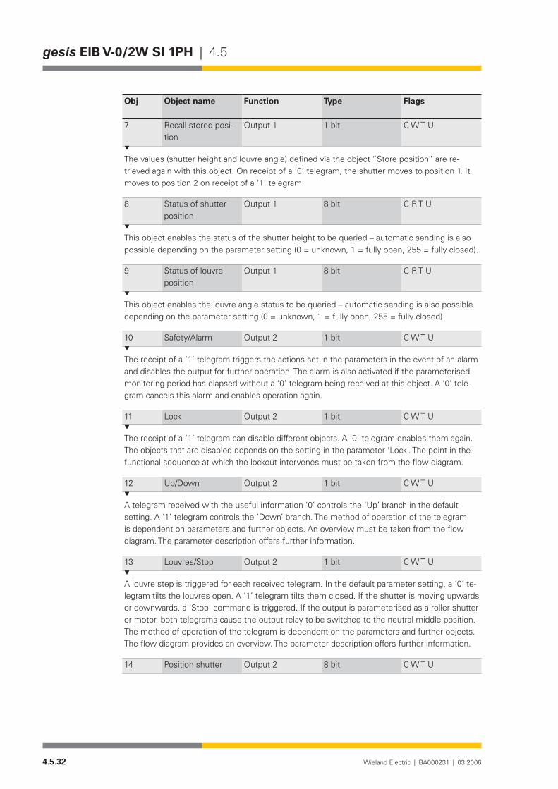
4.5.32 Wieland Electric | BA000231 | 03.2006
gesis EIB V-0/2W SI 1PH | 4.5
Obj Object name Function Type Flags
7 Recall stored posi-tion
Output 1 1 bit C W T U
The values (shutter height and louvre angle) defined via the object “Store position” are re-trieved again with this object. On receipt of a ‘0’ telegram, the shutter moves to position 1. It moves to position 2 on receipt of a ‘1’ telegram.
8 Status of shutter position
Output 1 8 bit C R T U
This object enables the status of the shutter height to be queried – automatic sending is also possible depending on the parameter setting (0 = unknown, 1 = fully open, 255 = fully closed).
9 Status of louvre position
Output 1 8 bit C R T U
This object enables the louvre angle status to be queried – automatic sending is also possible depending on the parameter setting (0 = unknown, 1 = fully open, 255 = fully closed).
10 Safety/Alarm Output 2 1 bit C W T U
The receipt of a ‘1’ telegram triggers the actions set in the parameters in the event of an alarm and disables the output for further operation. The alarm is also activated if the parameterised monitoring period has elapsed without a ‘0’ telegram being received at this object. A ‘0’ tele-gram cancels this alarm and enables operation again.
11 Lock Output 2 1 bit C W T U
The receipt of a ‘1’ telegram can disable different objects. A ‘0’ telegram enables them again. The objects that are disabled depends on the setting in the parameter ‘Lock’. The point in the functional sequence at which the lockout intervenes must be taken from the flow diagram.
12 Up/Down Output 2 1 bit C W T U
A telegram received with the useful information ‘0’ controls the ‘Up’ branch in the default setting. A ‘1’ telegram controls the ‘Down’ branch. The method of operation of the telegram is dependent on parameters and further objects. An overview must be taken from the flow diagram. The parameter description offers further information.
13 Louvres/Stop Output 2 1 bit C W T U
A louvre step is triggered for each received telegram. In the default parameter setting, a ‘0’ te-legram tilts the louvres open. A ‘1’ telegram tilts them closed. If the shutter is moving upwards or downwards, a ‘Stop’ command is triggered. If the output is parameterised as a roller shutter or motor, both telegrams cause the output relay to be switched to the neutral middle position. The method of operation of the telegram is dependent on the parameters and further objects. The flow diagram provides an overview. The parameter description offers further information.
14 Position shutter Output 2 8 bit C W T U
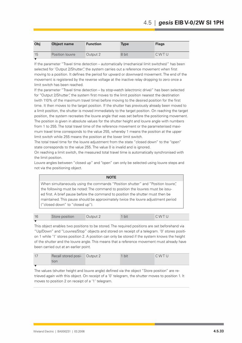
4.5.33Wieland Electric | BA000231 | 03.2006
4.5 | gesis EIB V-0/2W SI 1PH
Obj Object name Function Type Flags
15 Position louvre Output 2 8 bit C W T U
If the parameter “Travel time detection – automatically (mechanical limit switches)” has been selected for ‘Output 2/Shutter”, the system carries out a reference movement when first moving to a position. It defines the period for upward or downward movement. The end of the movement is registered by the reverse voltage at the inactive relay dropping to zero once a limit switch has been reached.If the parameter “Travel time detection – by stop-watch (electronic drive)” has been selected for “Output 2/Shutter”, the system first moves to the limit position nearest the destination (with 110% of the maximum travel time) before moving to the desired position for the first time. It then moves to the target position. If the shutter has previously already been moved to a limit position, the shutter is moved immediately to the target position. On reaching the target position, the system recreates the louvre angle that was set before the positioning movement.The position is given in absolute values for the shutter height and louvre angle with numbers from 1 to 255. The total travel time of the reference movement or the parameterised maxi-mum travel time corresponds to the value 255, whereby 1 means the position at the upper limit switch while 255 means the position at the lower limit switch.The total travel time for the louvre adjustment from the state “closed down” to the “open” state corresponds to the value 255. The value 0 is invalid and is ignored.On reaching a limit switch, the measured total travel time is automatically synchronised with the limit position.Louvre angles between “closed up” and “open” can only be selected using louvre steps and not via the positioning object.
NOTE
When simultaneously using the commands “Position shutter” and “Position louvre”, the following must be noted: The command to position the louvres must be issu-ed first. A brief pause before the command to position the shutter must then be maintained. This pause should be approximately twice the louvre adjustment period (“closed down” to “closed up”).
16 Store position Output 2 1 bit C W T U
This object enables two positions to be stored. The required positions are set beforehand via “Up/Down” and “Louvres/Stop” objects and stored on receipt of a telegram. ‘0’ stores positi-on 1 while ‘1’ stores position 2. A position can only be stored if the system knows the height of the shutter and the louvre angle. This means that a reference movement must already have been carried out at an earlier point.
17 Recall stored posi-tion
Output 2 1 bit C W T U
The values (shutter height and louvre angle) defined via the object “Store position” are re-trieved again with this object. On receipt of a ‘0’ telegram, the shutter moves to position 1. It moves to position 2 on receipt of a ‘1’ telegram.

4.5.34 Wieland Electric | BA000231 | 03.2006
gesis EIB V-0/2W SI 1PH | 4.5
Obj Object name Function Type Flags
18 Status of shutter position
Output 2 8 bit C R T U
This object enables the status of the shutter height to be queried – automatic sending is also possible depending on the parameter setting (0 = unknown, 1 = fully open, 255 = fully closed).
19 Status of louvre position
Output 2 8 bit C R T U
This object enables the louvre angle status to be queried – automatic sending is also possible depending on the parameter setting (0 = unknown, 1 = fully open, 255 = fully closed).
Parameterisation
Default settings are printed in bold type.
Parameters Settings
Behaviour in event of alarm alarm evaluation disabledmove upwardsmove downwardsstop
The shutter control function can be influenced by an alarm function. This function is controlled by the parameter “Behaviour in event of alarm”. Three reactions are possible: “move upwards”, “move downwards” and “stop”. The setting “alarm evaluation disabled” does not cause a reaction in the event of an alarm.
Base for monitoring time for alarm evaluation 1 sec2 sec5 sec10 sec20 sec1 min2 min5 min
Factor for monitoring time for alarm evaluation 255
Monitoring period for alarm evaluation = Base x Factor. These parameters define the period in which the monitoring must be triggered to prevent an alarm being tripped. The retriggering is carried out via the alarm object with a ‘0’ telegram and should be executed twice during a monitoring period. The monitoring period selected should not be too short as this increases the bus load.
After end of alarm no actionmove to previous position, if possible
Output 1/GeneralOutput 2/General
4.5.35Wieland Electric | BA000231 | 03.2006
4.5 | gesis EIB V-0/2W SI 1PH
Parameters Settings
Once the alarm has ended, it is possible to move to the position occupied prior to the alarm. This is only possible if there was a valid position before the alarm.
Operating mode with travel timecontinuous operation
If the operating mode “with travel time” is selected, the relays are switched to a neutral position once the travel time has elapsed. The output is then de-energised. If an automatic disconnection should not take place once a direction of rotation has been selected, the option “continuous operation” should be set. The output is then only de-energised via a “Louvres/Stop” command.
Direction of rotation normalinverted
If the direction of rotation has been mixed up when installing the motor, the output can be inverted with this parameter. So that all the commands and parameters can be retained, the inversion only takes effect immediately in front of the relays (see functional schematic).
Behaviour on bus voltage failure no actionmove upwardsmove downwardsstop
The set action is carried out in the event of a bus voltage failure. Caution: The relays must switch immediately on bus voltage failure. It is therefore not possible to maintain a pause on reverse.
Lock(the object numbers apply to output 1; for output 2 it is necessary to add 10)
disableaffects object 2affects object 3 affects objects 2 and 3
Note: If the operating mode “continuous operation” is set, the parameter “Lock” is displayed here with all the settings listed above. In the operating mode “with travel time”, this parameter is displayed on the page “Output x/Shutter” or “Output x/Roller blind”. The options are likewise dependent on the selected operating mode. The following description is therefore only valid for the operating mode “continuous operation”. If a ‘1’ is received at the ‘Lock’ object for the respective output, the selected objects in the parameter are disabled (the corresponding output is not modified as a result). On receipt of a ‘0’, these objects are enabled again. The commands that are accepted during the lockout are not carried out once the lockout has been cancelled. The disable function does not have any influence on the alarm function.
4.5.36 Wieland Electric | BA000231 | 03.2006
gesis EIB V-0/2W SI 1PH | 4.5
Parameters Settings
Base for pause on reverse 10 msec50 msec100 msec500 msec1 sec2 sec
Factor for pause on reverse (1-255) 9
Pause on reverse = base x factor. As a rapid change in direction with different motors can lead to the relay contacts being damaged, a pause on reverse must be maintained. This is defined by multiplying the “Base for pause on reverse” and the “Factor for pause on reverse”. With larger motor loads, the preset time of 900 ms must be increased. When the period is reduced, the motor manufacturer should be consulted regarding the minimum pause on reverse.
Parameters Settings
These pages are only visible if the operation mode “with travel time” has been set on the parameter page “Output 1/General” or “Output 2/General” and the operating mode “Shutter” has been set within it.
Operating mode ShutterRoller blind
This parameter describes whether a shutter with louvres or a roller blind is connected to the output. If the operating mode “Roller blind” is selected, the parameters responsible for con-trolling the louvres are no longer displayed.
Travel time detection automatically (mechanical limit switches)by stop-watch (electronic drive)
If the shutter has mechanical limit switches available (reverse voltage present), the travel time is measured automatically. If electronic limit switches or isolating relays are available, the travel time must be determined beforehand by a stop-watch and entered with the two subsequent parameters.
Base for maximum travel time(only for “automatic” travel time detection)
500 msec1 sec2 sec5 sec10 sec20 sec1 min2 min5 min10 min
Output 1/ShutterOutput 2/Shutter
4.5.37Wieland Electric | BA000231 | 03.2006
4.5 | gesis EIB V-0/2W SI 1PH
Parameters Settings
Factor for maximum travel time(only for “automatic” travel time detection)
150
Maximum travel time = “Base for maximum travel time” x “Factor for maximum travel time”If no reference movement has been carried out, the time given above is used as the maximum travel time for downward movement. The period is extended by 10% for upward movement. Once these times have been achieved, the output is de-energised so that the output is not continually live when the limit switches are not detected. As soon as a successful reference movement has been carried out, the time determined by the actuator itself for the correspon-ding output is used as the travel time.
Base for measured travel time(only visible for “Travel time detection by stop-watch”)
500 msec1 sec2 sec5 sec10 sec20 sec1 min2 min5 min10 min
Factor for measured travel time (10-255)(only visible for “Travel time detection by stop-watch”)
60
Measured travel time = “Base for measured travel time” x “Factor for measured travel time”The travel time for the shutter, determined using the stop-watch, is entered with these para-meters. This period is used to determine the height of the shutter (EIS6) for a drive without reversevoltageandfordownwardmovement(EIS7).Thetimeisextendedby10%forupwardmovement(EIS7).
Lock(the object numbers apply to output 1; for output 2 it is necessary to add 10)
disableaffects objects 2 and 3affects objects 4 and 5affectsobjects6and7affectsobjects2,3,6and7affectsobjects2…7
If a ‘1’ is received at the ‘Lock’ object for the respective output, the selected objects in the parameter are disabled (the corresponding output is not modified as a result). On receipt of a ‘0’, these objects are enabled again. The commands that are accepted during the lockout are not carried out once the lockout has been cancelled. The disable function does not have any influence on the alarm function.

4.5.38 Wieland Electric | BA000231 | 03.2006
gesis EIB V-0/2W SI 1PH | 4.5
Parameters Settings
Send status of shutter position on read requeston changeon change (not on bus voltage failure)
This parameter defines under which conditions the status of the shutter position is sent. If the current position is unknown (bus voltage failure, directly after parameterisation), the value ‘0’ is issued. If the status is ‘1’, the shutter is at the top while if the status is ‘255’, it is at the bottom.Ifoneoftheautomaticfunctionsisselected(“onchange…”),itmustbenotedthatthiscanconsiderably increase the bus load.
Parameters Settings
These pages are only visible if the operation mode “with travel time” has been set on the parameter page “Output 1/General” or “Output 2/General” and the operating mode “Roller blind” has been set within it.
Operating mode ShutterRoller blind
This parameter describes whether a shutter with louvres or a roller blind is connected to the output. If the operating mode “Roller blind” is selected, the parameters and objects responsi-ble for controlling the louvres are no longer displayed.
Travel time detection automatically (mechanical limit switches)by stop-watch (electronic drive)
If the roller blind has mechanical limit switches available, the travel time is measured auto-matically. If electronic limit switches or isolating relays are available, the travel time must be determined beforehand by a stop-watch and entered with the corresponding parameters.
Base for maximum travel time(only for “automatic” travel time detection)
500 msec1 sec2 sec5 sec10 sec20 sec1 min2 min5 min10 min
Factor for maximum travel time(only for “automatic” travel time detection)
150
Maximum travel time = “Base for maximum travel time” x “Factor for maximum travel time”If no reference movement has been carried out, the time given above is used as the maximum travel time for downward movement. The period is extended by 10% for upward movement. Once these times have been achieved, the output is de-energised so that the output is not continually live when the limit switches are not detected. As soon as a successful reference movement has been carried out, the time determined by the actuator itself for the correspon-ding output is used as the travel time.
Output 1/Roller blindOutput 2/Roller blind
4.5.39Wieland Electric | BA000231 | 03.2006
4.5 | gesis EIB V-0/2W SI 1PH
Base for measured travel time(only visible for “Travel time detection by stop-watch”)
500 msec1 sec2 sec5 sec10 sec20 sec1 min2 min5 min10 min
Factor for measured travel time (10-255)(only visible for “Travel time detection by stop-watch”)
60
Measured travel time = “Base for measured travel time” x “Factor for measured travel time”The travel time for the roller blind, determined using the stop-watch, is entered with these pa-rameters. This period is used to determine the height of the shutter (EIS6) for a drive without reversevoltageandfordownwardmovement(EIS7).Thetimeisextendedby10%forupwardmovement(EIS7).
Base for moving up in lower position 10 msec50 msec100 msec500 msec1 sec2 sec
Factor for moving up in lower position (0-255) 0
Period for moving upwards until the lower limit position is reached = Base x FactorIf the roller blind should be moved upwards slightly once the upper limit position has been reached, the required travel time can be set via this parameter. The upward movement is only carriedoutiftherollerblindhasmoveddownwardsviaobjects2or12(Up/Down,EIS7).
Lock(the object numbers apply to output 1; for output 2 it is necessary to add 10)
disableaffects objects 2 and 3affects object 4 affectsobjects6and7affectsobjects2,3,6and7affectsobjects2…7
If a ‘1’ is received at the ‘Lock’ object for the respective output, the selected objects in the parameter are disabled (the corresponding output is not modified as a result). On receipt of a ‘0’, these objects are enabled again. The commands that are accepted during the lockout are not carried out once the lockout has been cancelled. The disable function does not have any influence on the alarm function.
Send status of shutter position on read requeston changeon change (not on bus voltage failure)
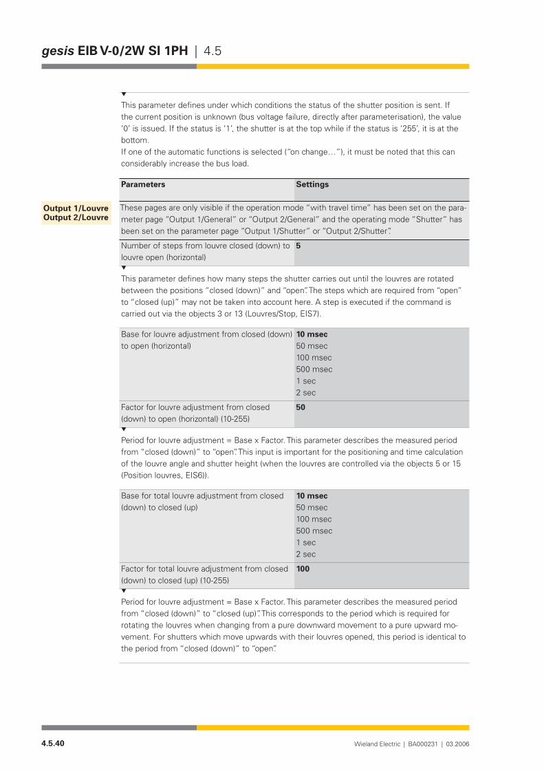
4.5.40 Wieland Electric | BA000231 | 03.2006
gesis EIB V-0/2W SI 1PH | 4.5
This parameter defines under which conditions the status of the shutter position is sent. If the current position is unknown (bus voltage failure, directly after parameterisation), the value ‘0’ is issued. If the status is ‘1’, the shutter is at the top while if the status is ‘255’, it is at the bottom.Ifoneoftheautomaticfunctionsisselected(“onchange…”),itmustbenotedthatthiscanconsiderably increase the bus load.
Parameters Settings
These pages are only visible if the operation mode “with travel time” has been set on the para-meter page “Output 1/General” or “Output 2/General” and the operating mode “Shutter” has been set on the parameter page “Output 1/Shutter” or “Output 2/Shutter”.
Number of steps from louvre closed (down) to louvre open (horizontal)
5
This parameter defines how many steps the shutter carries out until the louvres are rotated between the positions “closed (down)” and “open”. The steps which are required from “open” to “closed (up)” may not be taken into account here. A step is executed if the command is carriedoutviatheobjects3or13(Louvres/Stop,EIS7).
Base for louvre adjustment from closed (down) to open (horizontal)
10 msec50 msec100 msec500 msec1 sec2 sec
Factor for louvre adjustment from closed (down) to open (horizontal) (10-255)
50
Period for louvre adjustment = Base x Factor. This parameter describes the measured period from “closed (down)” to “open”. This input is important for the positioning and time calculation of the louvre angle and shutter height (when the louvres are controlled via the objects 5 or 15 (Position louvres, EIS6)).
Base for total louvre adjustment from closed (down) to closed (up)
10 msec50 msec100 msec500 msec1 sec2 sec
Factor for total louvre adjustment from closed (down) to closed (up) (10-255)
100
Period for louvre adjustment = Base x Factor. This parameter describes the measured period from “closed (down)” to “closed (up)”. This corresponds to the period which is required for rotating the louvres when changing from a pure downward movement to a pure upward mo-vement. For shutters which move upwards with their louvres opened, this period is identical to the period from “closed (down)” to “open”.
Output 1/louvreOutput 2/louvre
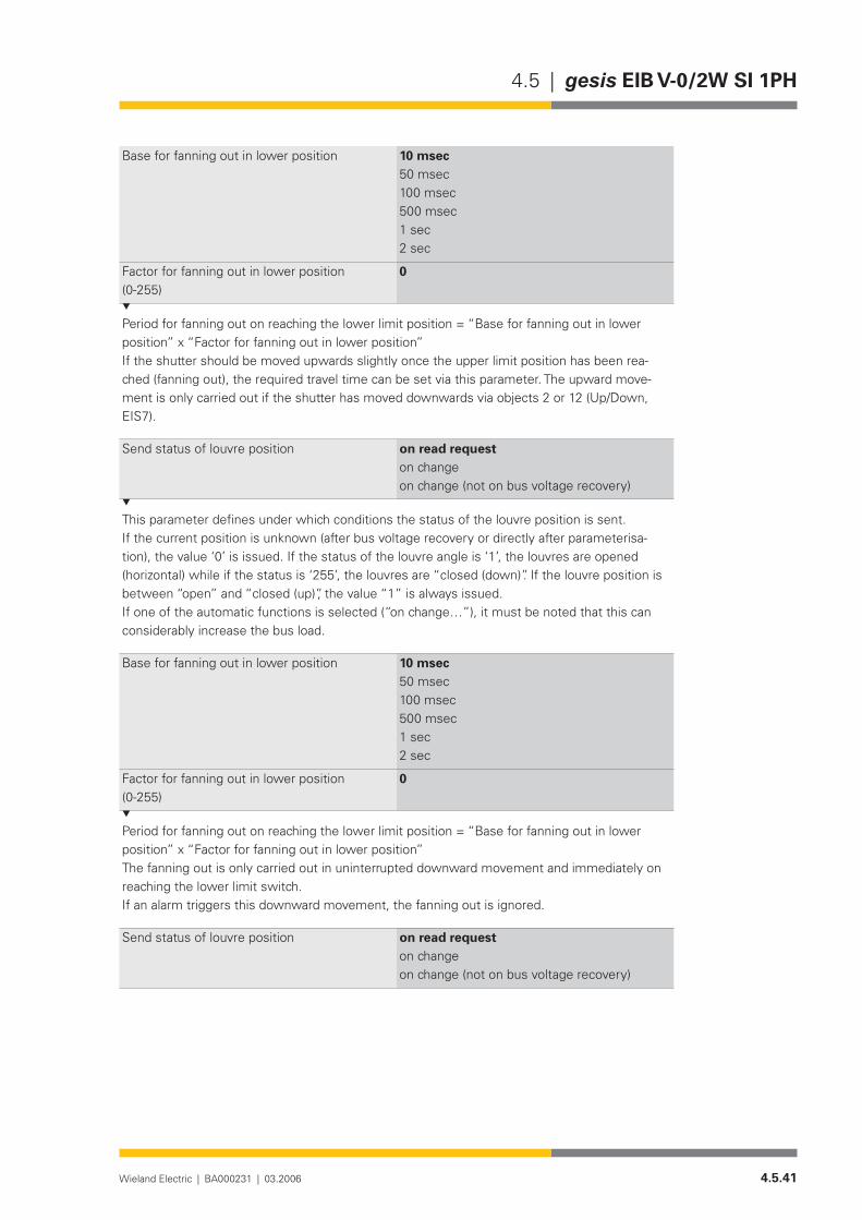
4.5.41Wieland Electric | BA000231 | 03.2006
4.5 | gesis EIB V-0/2W SI 1PH
Base for fanning out in lower position 10 msec50 msec100 msec500 msec1 sec2 sec
Factor for fanning out in lower position (0-255)
0
Period for fanning out on reaching the lower limit position = “Base for fanning out in lower position” x “Factor for fanning out in lower position”If the shutter should be moved upwards slightly once the upper limit position has been rea-ched (fanning out), the required travel time can be set via this parameter. The upward move-ment is only carried out if the shutter has moved downwards via objects 2 or 12 (Up/Down, EIS7).
Send status of louvre position on read requeston changeon change (not on bus voltage recovery)
This parameter defines under which conditions the status of the louvre position is sent. If the current position is unknown (after bus voltage recovery or directly after parameterisa-tion), the value ‘0’ is issued. If the status of the louvre angle is ‘1’, the louvres are opened (horizontal) while if the status is ‘255’, the louvres are “closed (down)”. If the louvre position is between “open” and “closed (up)”, the value “1” is always issued.Ifoneoftheautomaticfunctionsisselected(“onchange…”),itmustbenotedthatthiscanconsiderably increase the bus load.
Base for fanning out in lower position 10 msec50 msec100 msec500 msec1 sec2 sec
Factor for fanning out in lower position (0-255)
0
Period for fanning out on reaching the lower limit position = “Base for fanning out in lower position” x “Factor for fanning out in lower position”The fanning out is only carried out in uninterrupted downward movement and immediately on reaching the lower limit switch.If an alarm triggers this downward movement, the fanning out is ignored.
Send status of louvre position on read requeston changeon change (not on bus voltage recovery)

4.5.42 Wieland Electric | BA000231 | 03.2006
gesis EIB V-0/2W SI 1PH | 4.5
This parameter defines under which conditions the status of the louvre position is sent. If the current position is unknown (bus voltage failure, directly after parameterisation), the value ‘0’ is issued. If the status of the louvre angle is ‘1’, the louvres are open and horizontal. If the status is ‘255’, the louvres are “closed (down)”. If the louvre position is between “open” and “closed (up)”, the value “1” is always issued.Ifoneoftheautomaticfunctionsisselected(“onchange…”),itmustbenotedthatthiscanconsiderably increase the bus load.

4.5.43Wieland Electric | BA000231 | 03.2006
4.5 | gesis EIB V-0/6

4.5.44 Wieland Electric | BA000231 | 03.2006
gesis EIB V-0/6 | 4.5
4.6.1Wieland Electric | BA000231 | 03.2006
4.6 | gesis EIB V-0/6
gesis EIB V-0/6
Product description
Designation• Switch actuator, 6-foldType• gesis EIB V-0/6Part number• 83.020.0214.0Device type• EIB switch actuator, 6-fold Non-floating switch outputs 230 V
ACDesign• Device with plug-in connections for surface mounting in enc-
losed rooms, fixing with two screwsETS2 application program• gesis EIB V-0/6 1.0
Function
The 6-fold switch output receives telegrams from the EIB bus and controls six independent switch outputs. Three outputs are led externally via a black, 5 pole, GST 18i5 connector with code 1 and the assignment A1/4, A2/5, A3/6, N and PE. End consumers which require three outputs can thus be connected directly (e.g. 3-phase lighting strips). The six circuits can also be connected individually via additional distribution blocks.
The switch outputs are non-floating. That means that each output is already linked internally with the potentials N, PE and linked with an outer conductor of the mains voltage via a corre-sponding relay contact.
The outputs can be controlled separately via the following parameters:Behaviour on bus voltage failure, behaviour on bus voltage recovery, evaluation of a disable
object, operating modes: “normal”, “ON delay”, “OFF delay” and “time switch”, relay operation (“make contact” or “break contact”), method of sending the status object (“automatic” or “on request”).
The switching of the bistable relay is only possible if the bus and mains voltage are present. In addition, four scenes can be parameterised and retrieved on all six outputs. The parameterisa-tion and operation of the device requires application software. It is loaded into the device using EIB Tool Software (ETS2).
Functional elements
Programming button• Pressing the programming button switches the programming mode on or off (toggle function).
LED (red)• The LED indicates whether the programming mode is active.

4.6.2 Wieland Electric | BA000231 | 03.2006
gesis EIB V-0/6 | 4.6
Technical data
Bus connection Connection type BST 14i2L male connector, 2 pole, green (EIB coding), (1+/2-)Bus voltage 24 V DC (-4V/+6V)Current consumption approx. 6 mAPower consumption approx. 150 mWMains connectionConnection type GST 18i5 male connector, 5 pole, black, (1/2/PE/N/3)Rated voltage 230/400 V AC (-15%/+10%)Rated frequency 50-60 HzRated current 16APower consumption Internally typ. 2.5 VA (connection 1 – L1) + externally connec-
ted loadsFusing 3 pole circuit-breaker B16ASwitch outputsNumber 6 switch outputsConnection type Connector from the GST 18i5 range, 5 pole male connector,
coding 1, mains with PE, blackRated voltage 230 V ACEquipotential distribution Connector 1 A1 – Pin 1 – Outer conductor L1
A2 – Pin 2 – Outer conductor L2 A3 – Pin 3 – Outer conductor L3
Connector 2 A4 – Pin 1 – Outer conductor L1 A5 – Pin 2 – Outer conductor L2 A6 – Pin 3 – Outer conductor L3
Rated current 16 A (resistive load)Maximum capacitor load 35 µF (corresponds to 5 x 58 W fluorescent lamps, with paral-
lelcompensationof7mFeach)Minimum load 2.5 VASwitching capacity/ service life 4000 VA cos ϕ = 1: 5 ⋅ 104 switching cycles
1000 VA incandescent: 3 ⋅ 105 switching cycles lamp load: 104 switching cycles 5 x 58 VA fluorescent lamps (withparallelcompensationof7µFeach)
Electrical safetyProtection class IType of protection IP 20 (in accordance with EN 60529)Degree of pollution 2Overvoltage category IIIRated insulation voltage 250 V outer conductor against N or PE
400 V outer conductor against outer conductorEIB bus protection measure SELV (24 V DC)Contact opening of relay µ contactElectrical isolation Creepage distance and clearance > 5.5 mm EIB bus/mains
test voltage 4 kV AC/6 kV pulseConditions of useOperating conditionsArea of application For permanent, surface-mounted installation, in interior rooms
and dry roomsOperating temperature −5…+45°C
Bus connection
Mains connection
Switch outputs
Electrical safety
Conditions of use

4.6.3Wieland Electric | BA000231 | 03.2006
4.6 | gesis EIB V-0/6
Storage temperature −25…+70°CRelative humidity 5%…93%Moisture condensation Not permittedOperating height max. 2000 m above NN
(without performance or functional impairment)EMC requirements EN 50090-2-2, EN 61000-6-2, EN 61000-6-3 Climatic withstand capability EN 50090-2-2Housing material Plastic,halogen-andphosphorous-free,lightgreyRAL7035Fire behaviour (housing) V-2 in accordance with UL 94 (consists of glow-wire test at
960°CinaccordancewithIEC695-2-1)Fire load approx. 2.9 kWhWeight approx. 410 gDimensions (W x H x D) 254 mm x 112 mm x 32 mmApproval KNX/EIB-certifiedCE mark In accordance with the EMC guideline (residential and functio-
nal buildings), low voltage guideline
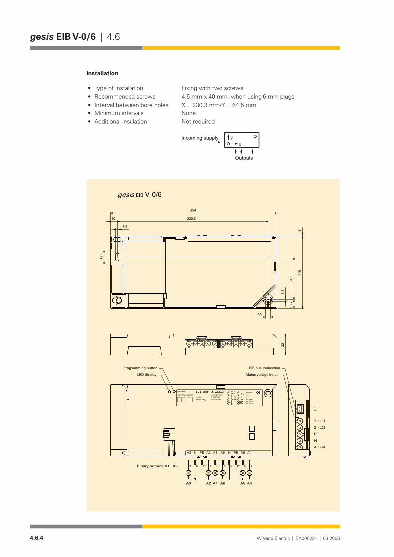
4.6.4 Wieland Electric | BA000231 | 03.2006
gesis EIB V-0/6 | 4.6
Installation
Type of installation• Fixing with two screwsRecommended screws • 4.5 mm x 40 mm, when using 6 mm plugsInterval between bore holes• X = 230.3 mm/Y = 64.5 mmMinimum intervals • None Additional insulation • Not required
�
����������������
�������
254
110
13,7
64,5
5,5
5,5
10
12
230,3
7,5
2
EIB V-0/6gesis
+-
3 (L3)
N
PE
2 (L2)
1 (L1)
32
Binary outputs A1...A6
DEVICELINEAREA
PHYSICAL ADDRESS:
PROGRAM
230/400V50/60Hz; 16A 83.020.0214.0
EIB V-0/66 OUTPUTS
A1...3230/400V~
m16A
N PE
A4...6
3 2 1
A2, A5 = L2A3, A6 = L3
A1, A4 = L1
gesiswielandw
N PE3 2 1123 PEN
A4A5NA6 PENA3 A2 A1PE
A6 A5 A4A1A2A3
Mains voltage input
EIB bus connectionProgramming button
LED display

4.6.5Wieland Electric | BA000231 | 03.2006
4.6 | gesis EIB V-0/6
Accessories
Accessories for 83.020.0214.0 gesis EIB V-0/6
Incoming supply when using the flat cable system (7 pole)7poleflatcable• 00.702.0323.9EIB adapter• 93.421.0853.0Mains adapter• 92.051.0353.1
Incoming supply via combination connector (EST 2i5)Combination distribution block• 93.550.0053.1Combination connector, female connector• 93.551.0553.1Combination starter cable, female – free end• 94.553.x003.7(x=Lengthinmetres)Combination extension cable, female – male• 94.553.x000.7(x=Lengthinmetres)
Separate incoming supply for mains (GST 18i5) and EIB (BST 14i2)Mains, female connector, screw connection• 92.953.3053.1Mains, starter lead, female – free end• 92.258.x003.1 (x = Length in metres)Mains, extender lead, female – male• 92.258.x000.1 (x = Length in metres)EIB, female connector, spring-loaded connection • 93.421.0553.1EIB, starter lead, female – free end • 94.425.x003.7(x=Lengthinmetres)EIB, extender lead, female – male • 94.425.x000.7(x=Lengthinmetres)
EIB branch (BST 14i2) when using the combination distribution blockEIB, male connector, spring-loaded connection• 93.422.0553.1EIB, starter lead, male – free end• 94.425.x004.7(x=Lengthinmetres)EIB, extender lead, female – male• 94.425.x000.7(x=Lengthinmetres)
Switch outputs (GST 18i3)Male connector, spring-loaded connection• 92.934.0053.1Starter lead, male – free end• 92.232.x004.1 (x = Length in metres)Extender lead, male – female• 92.232.x000.1 (x = Length in metres)
SoftwareProduct database for import in ETS2 •from version V1.1
www.gesis.com (see under Info Service/Download/gesis product database)
Diskette• 00.000.0066.1

4.6.6 Wieland Electric | BA000231 | 03.2006
gesis EIB V-0/6 | 4.6

4.6.7Wieland Electric | BA000231 | 03.2006
4.6 | gesis EIB V-0/6
Application program
Program name• gesis EIB V-0/6 1.0Program version• 1.0Product assignment• gesis EIB V-0/6, 83.020.0214.0Reference source• www.gesis.com Info Service/Download/gesis product databa-
seProduct description • EIB switch actuator 6-fold switch output 230 V AC Non-floating
outputs, all plug-in connections, surface mounting ETS2 search path• Manufacturer: Wieland Electric GmbH
Product family: gesis EIB V Product type: Output – Binary output, 6-fold
The application program controls the six binary outputs of the EIB switch actuator.The switch outputs can be controlled separately. Each group of three outputs are led on a 5 pole connector of the GST 18i5 range, code 1, black. In addition to the three individually
switched phases, the connector also leads the N conductor and the protective conductor (PE). The following parameters are available for each channel: behaviour on bus voltage failure,
behaviour on bus voltage recovery, evaluation of a disable object, operating modes: “normal”, “ON delay”, “OFF delay” and “time switch”, relay operation (“make contact” or “break con-tact”), method of sending the status object (“automatic” or “on request”).
There is a switch and status object available per channel. The common disable object makes it possible to block channels for further operation. The disable function can be evaluated indivi-dually for each channel.
Preset switching states can be retrieved in four parameterised scenes via two scene ob-jects. The preset option is carried out via a parameter page.
General description
Function
Flow diagram
�������
����������
����������������
����������������������������
�����������
����������������������
�����������������������������
����������������������������
��������������������������
��������������������
������
�����������������������
����������������
�����������������������������������
�������
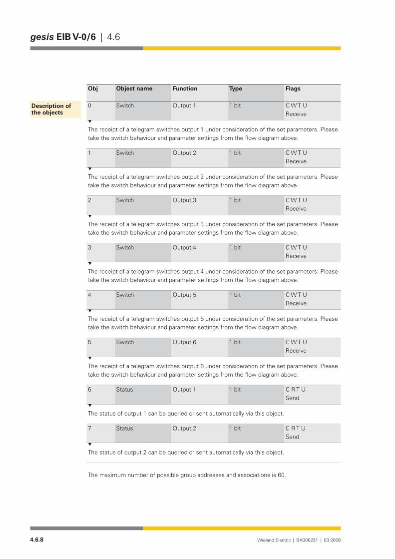
4.6.8 Wieland Electric | BA000231 | 03.2006
gesis EIB V-0/6 | 4.6
Obj Object name Function Type Flags
0 Switch Output 1 1 bit C W T UReceive
The receipt of a telegram switches output 1 under consideration of the set parameters. Please take the switch behaviour and parameter settings from the flow diagram above.
1 Switch Output 2 1 bit C W T UReceive
The receipt of a telegram switches output 2 under consideration of the set parameters. Please take the switch behaviour and parameter settings from the flow diagram above.
2 Switch Output 3 1 bit C W T UReceive
The receipt of a telegram switches output 3 under consideration of the set parameters. Please take the switch behaviour and parameter settings from the flow diagram above.
3 Switch Output 4 1 bit C W T UReceive
The receipt of a telegram switches output 4 under consideration of the set parameters. Please take the switch behaviour and parameter settings from the flow diagram above.
4 Switch Output 5 1 bit C W T UReceive
The receipt of a telegram switches output 5 under consideration of the set parameters. Please take the switch behaviour and parameter settings from the flow diagram above.
5 Switch Output 6 1 bit C W T UReceive
The receipt of a telegram switches output 6 under consideration of the set parameters. Please take the switch behaviour and parameter settings from the flow diagram above.
6 Status Output 1 1 bit C R T USend
The status of output 1 can be queried or sent automatically via this object.
7 Status Output 2 1 bit C R T USend
The status of output 2 can be queried or sent automatically via this object.
The maximum number of possible group addresses and associations is 60.
Description of the objects
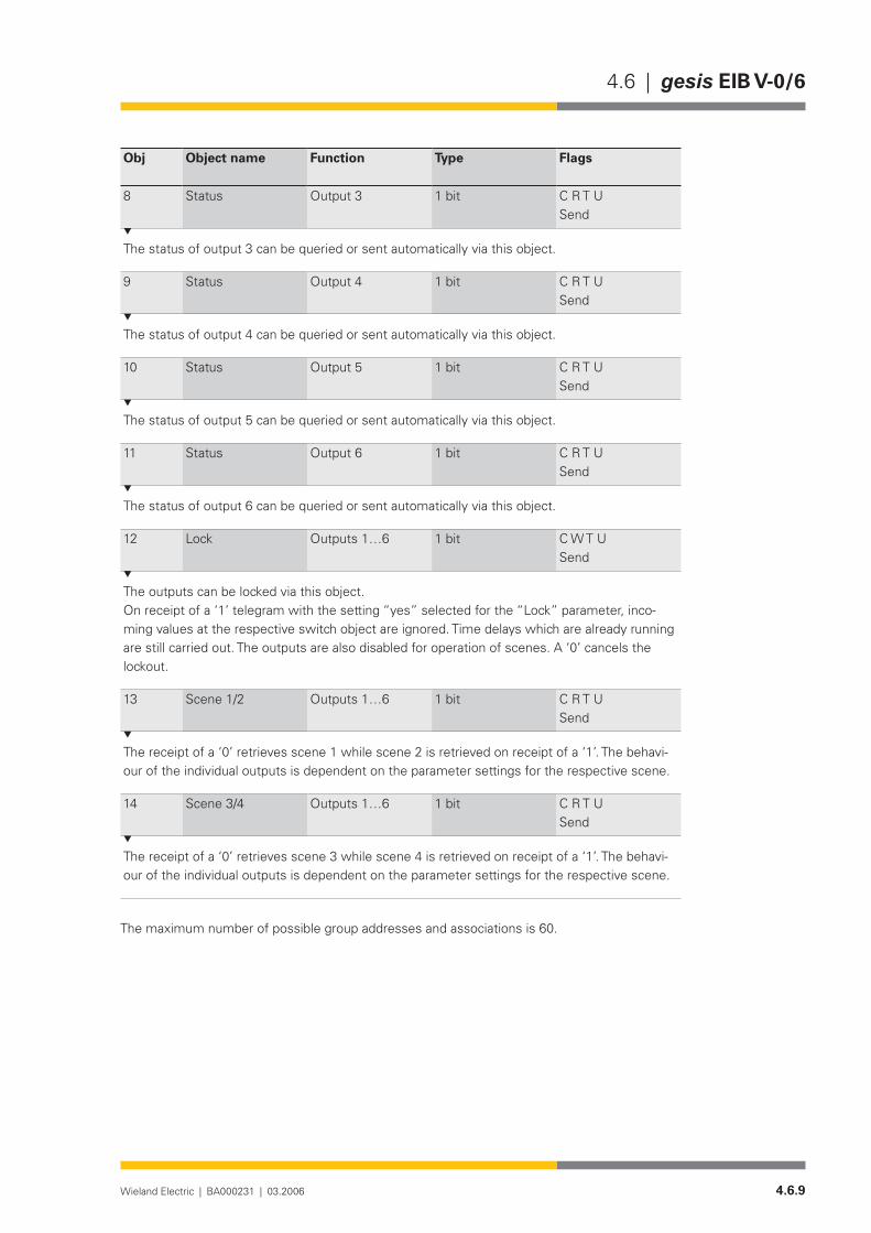
4.6.9Wieland Electric | BA000231 | 03.2006
4.6 | gesis EIB V-0/6
Obj Object name Function Type Flags
8 Status Output 3 1 bit C R T USend
The status of output 3 can be queried or sent automatically via this object.
9 Status Output 4 1 bit C R T USend
The status of output 4 can be queried or sent automatically via this object.
10 Status Output 5 1 bit C R T USend
The status of output 5 can be queried or sent automatically via this object.
11 Status Output 6 1 bit C R T USend
The status of output 6 can be queried or sent automatically via this object.
12 Lock Outputs1…6 1 bit C W T USend
The outputs can be locked via this object.On receipt of a ‘1’ telegram with the setting “yes” selected for the “Lock” parameter, inco-ming values at the respective switch object are ignored. Time delays which are already running are still carried out. The outputs are also disabled for operation of scenes. A ‘0’ cancels the lockout.
13 Scene 1/2 Outputs1…6 1 bit C R T USend
The receipt of a ‘0’ retrieves scene 1 while scene 2 is retrieved on receipt of a ‘1’. The behavi-our of the individual outputs is dependent on the parameter settings for the respective scene.
14 Scene 3/4 Outputs1…6 1 bit C R T USend
The receipt of a ‘0’ retrieves scene 3 while scene 4 is retrieved on receipt of a ‘1’. The behavi-our of the individual outputs is dependent on the parameter settings for the respective scene.
The maximum number of possible group addresses and associations is 60.

4.6.10 Wieland Electric | BA000231 | 03.2006
gesis EIB V-0/6 | 4.6
Parameterisation
Default settings are printed in bold type.
Parameters Settings
Behaviour on bus voltage failure no actionswitch onswitch off
This parameter determines how the bistable relay behaves on bus voltage failure. If “no ac-tion” is set, the relay remains in the current position. If “switch on” or “switch off” is selected, the corresponding state is created without consideration of the parameter settings.
Behaviour on bus voltage recovery no actionswitch onswitch off
This parameter determines how the bistable relay behaves on bus voltage recovery. If “no ac-tion” is set, the relay remains in the current position. If “switch on” or “switch off” is selected, the corresponding state is created without consideration of the parameter settings.
Lock noyes
If the output should be disabled on receipt of a ‘1’ value, “yes” must be selected. The output is then inactive, running time delays are still processed but scene retrieval is ignored for the disabled output.
Switch behaviour make contactbreak contact
To achieve maximum flexibility, the relay can be parameterised as a make contact or break contact. This parameter engages directly with the relay and acts as an inversion of the output.
Status read onlysend on change
The status of the output relay can be sent automatically on the bus after a change (“send on change”).
Operating mode normalON delayOFF delayON and OFF delaytime switch
In the “normal” operating mode, there are no delays. In the other operating modes, the corre-sponding parameters are displayed.
Output 1 Output 2 Output 3 Output 4 Output 5 Output 6

4.6.11Wieland Electric | BA000231 | 03.2006
4.6 | gesis EIB V-0/6
Base for ON delay(only visible in operating modes “ON delay” and “ON and OFF delay”)
130 msec260 msec520 msec1.0 sec2.1 sec4.2 sec8.4 sec17sec34 sec1 min 6 sec2 min 12 sec4 min 30 sec9 min18 min35 min1 h 12 min
FactorforONdelay(5-127)(only visible in operating modes “ON delay” and “ON and OFF delay”)
5
Period for ON delay = Base x Factor. The parameters “Base for ON delay” and “Factor for ON delay” define the duration of the ON delay. This period is the time which elapses on receipt of a ‘1’ telegram until the relay is switched on.
Base for OFF delay(only visible in operating modes “OFF delay” and “ON and OFF delay”)
130 msec260 msec520 msec1.0 sec2.1 sec4.2 sec8.4 sec17sec34 sec1 min 6 sec2 min 12 sec4 min 30 sec9 min18 min35 min1 h 12 min
FactorforOFFdelay(5-127)(only visible in operating modes “OFF delay” and “ON and OFF delay”)
5
Period for OFF delay = Base x Factor. The parameters “Base for OFF delay” and “Factor for OFF delay” define the duration of the OFF delay. This period is the time which elapses on receipt of a ‘0’ telegram until the relay is switched off.
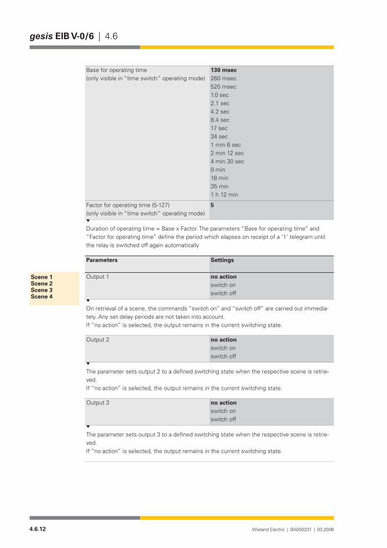
4.6.12 Wieland Electric | BA000231 | 03.2006
gesis EIB V-0/6 | 4.6
Base for operating time(only visible in “time switch” operating mode)
130 msec260 msec520 msec1.0 sec2.1 sec4.2 sec8.4 sec17sec34 sec1 min 6 sec2 min 12 sec4 min 30 sec9 min18 min35 min1 h 12 min
Factorforoperatingtime(5-127)(only visible in “time switch” operating mode)
5
Duration of operating time = Base x Factor. The parameters “Base for operating time” and “Factor for operating time” define the period which elapses on receipt of a ‘1’ telegram until the relay is switched off again automatically
Parameters Settings
Output 1 no actionswitch onswitch off
On retrieval of a scene, the commands “switch on” and “switch off” are carried out immedia-tely. Any set delay periods are not taken into account. If “no action” is selected, the output remains in the current switching state.
Output 2 no actionswitch onswitch off
The parameter sets output 2 to a defined switching state when the respective scene is retrie-ved. If “no action” is selected, the output remains in the current switching state.
Output 3 no actionswitch onswitch off
The parameter sets output 3 to a defined switching state when the respective scene is retrie-ved. If “no action” is selected, the output remains in the current switching state.
Scene 1 Scene 2 Scene 3 Scene 4
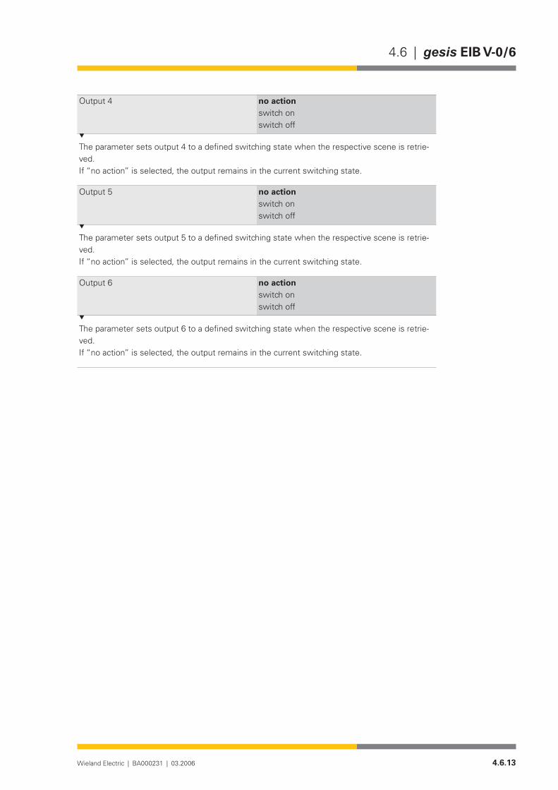
4.6.13Wieland Electric | BA000231 | 03.2006
4.6 | gesis EIB V-0/6
Output 4 no actionswitch onswitch off
The parameter sets output 4 to a defined switching state when the respective scene is retrie-ved. If “no action” is selected, the output remains in the current switching state.
Output 5 no actionswitch onswitch off
The parameter sets output 5 to a defined switching state when the respective scene is retrie-ved. If “no action” is selected, the output remains in the current switching state.
Output 6 no actionswitch onswitch off
The parameter sets output 6 to a defined switching state when the respective scene is retrie-ved. If “no action” is selected, the output remains in the current switching state.

4.6.14 Wieland Electric | BA000231 | 03.2006
gesis EIB V-0/6 | 4.6
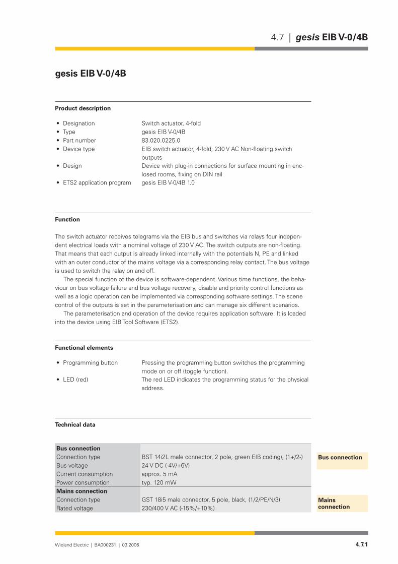
4.7.1Wieland Electric | BA000231 | 03.2006
4.7 | gesis EIB V-0/4B
gesis EIB V-0/4B
Product description
Designation• Switch actuator, 4-foldType• gesis EIB V-0/4BPart number• 83.020.0225.0Device type• EIB switch actuator, 4-fold, 230 V AC Non-floating switch
outputsDesign• Device with plug-in connections for surface mounting in enc-
losed rooms, fixing on DIN railETS2 application program• gesis EIB V-0/4B 1.0
Function
The switch actuator receives telegrams via the EIB bus and switches via relays four indepen-dent electrical loads with a nominal voltage of 230 V AC. The switch outputs are non-floating. That means that each output is already linked internally with the potentials N, PE and linked with an outer conductor of the mains voltage via a corresponding relay contact. The bus voltage is used to switch the relay on and off.
The special function of the device is software-dependent. Various time functions, the beha-viour on bus voltage failure and bus voltage recovery, disable and priority control functions as well as a logic operation can be implemented via corresponding software settings. The scene control of the outputs is set in the parameterisation and can manage six different scenarios.
The parameterisation and operation of the device requires application software. It is loaded into the device using EIB Tool Software (ETS2).
Functional elements
Programming button• Pressing the programming button switches the programming mode on or off (toggle function).
LED (red)• The red LED indicates the programming status for the physical address.
Technical data
Bus connectionConnection type BST 14i2L male connector, 2 pole, green EIB coding), (1+/2-)Bus voltage 24 V DC (-4V/+6V)Current consumption approx. 5 mAPower consumption typ. 120 mWMains connectionConnection type GST 18i5 male connector, 5 pole, black, (1/2/PE/N/3)Rated voltage 230/400 V AC (-15%/+10%)
Bus connection
Mains connection
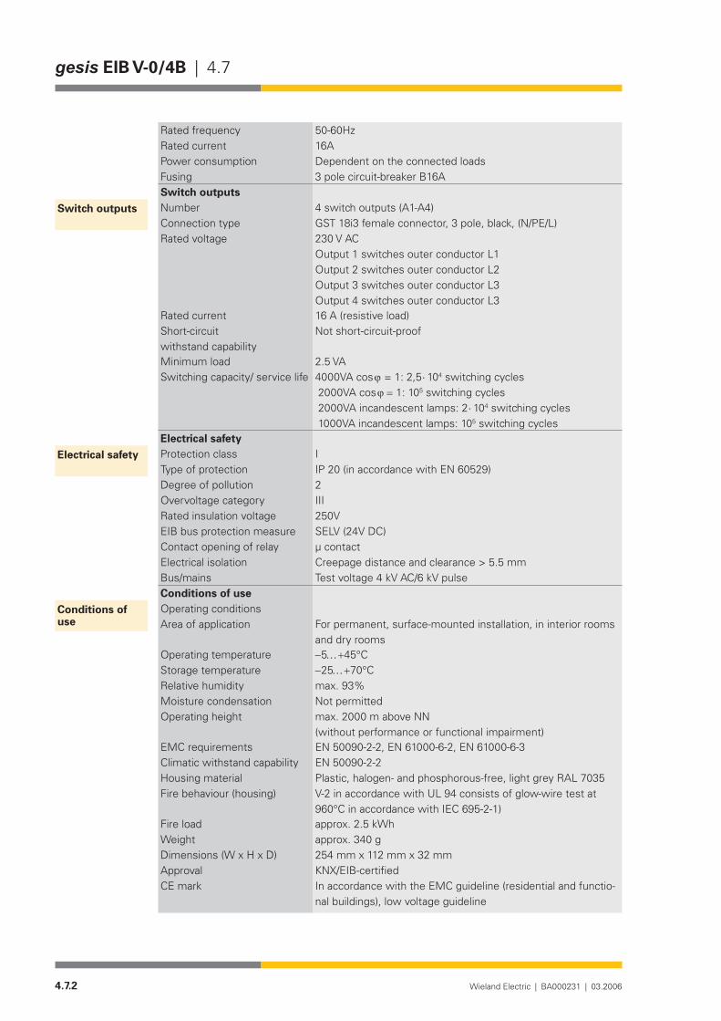
4.7.2 Wieland Electric | BA000231 | 03.2006
gesis EIB V-0/4B | 4.7
Rated frequency 50-60HzRated current 16APower consumption Dependent on the connected loadsFusing 3 pole circuit-breaker B16ASwitch outputsNumber 4 switch outputs (A1-A4)Connection type GST 18i3 female connector, 3 pole, black, (N/PE/L)Rated voltage 230 V AC
Output 1 switches outer conductor L1 Output 2 switches outer conductor L2 Output 3 switches outer conductor L3 Output 4 switches outer conductor L3
Rated current 16 A (resistive load)Short-circuit withstand capability
Not short-circuit-proof
Minimum load 2.5 VASwitching capacity/ service life 4000VA cos ϕ = 1: 2,5 ⋅ 104 switching cycles
2000VA cos ϕ = 1: 105 switching cycles 2000VA incandescent lamps: 2 ⋅ 104 switching cycles 1000VA incandescent lamps: 105 switching cycles
Electrical safetyProtection class IType of protection IP 20 (in accordance with EN 60529)Degree of pollution 2Overvoltage category IIIRated insulation voltage 250VEIB bus protection measure SELV (24V DC)Contact opening of relay µ contactElectrical isolation Creepage distance and clearance > 5.5 mmBus/mains Test voltage 4 kV AC/6 kV pulseConditions of useOperating conditionsArea of application For permanent, surface-mounted installation, in interior rooms
and dry roomsOperating temperature −5…+45°CStorage temperature −25…+70°CRelative humidity max. 93%Moisture condensation Not permittedOperating height max. 2000 m above NN
(without performance or functional impairment)EMC requirements EN 50090-2-2, EN 61000-6-2, EN 61000-6-3 Climatic withstand capability EN 50090-2-2Housing material Plastic,halogen-andphosphorous-free,lightgreyRAL7035Fire behaviour (housing) V-2 in accordance with UL 94 consists of glow-wire test at
960°CinaccordancewithIEC695-2-1)Fire load approx. 2.5 kWhWeight approx. 340 gDimensions (W x H x D) 254 mm x 112 mm x 32 mmApproval KNX/EIB-certifiedCE mark In accordance with the EMC guideline (residential and functio-
nal buildings), low voltage guideline
Switch outputs
Electrical safety
Conditions of use
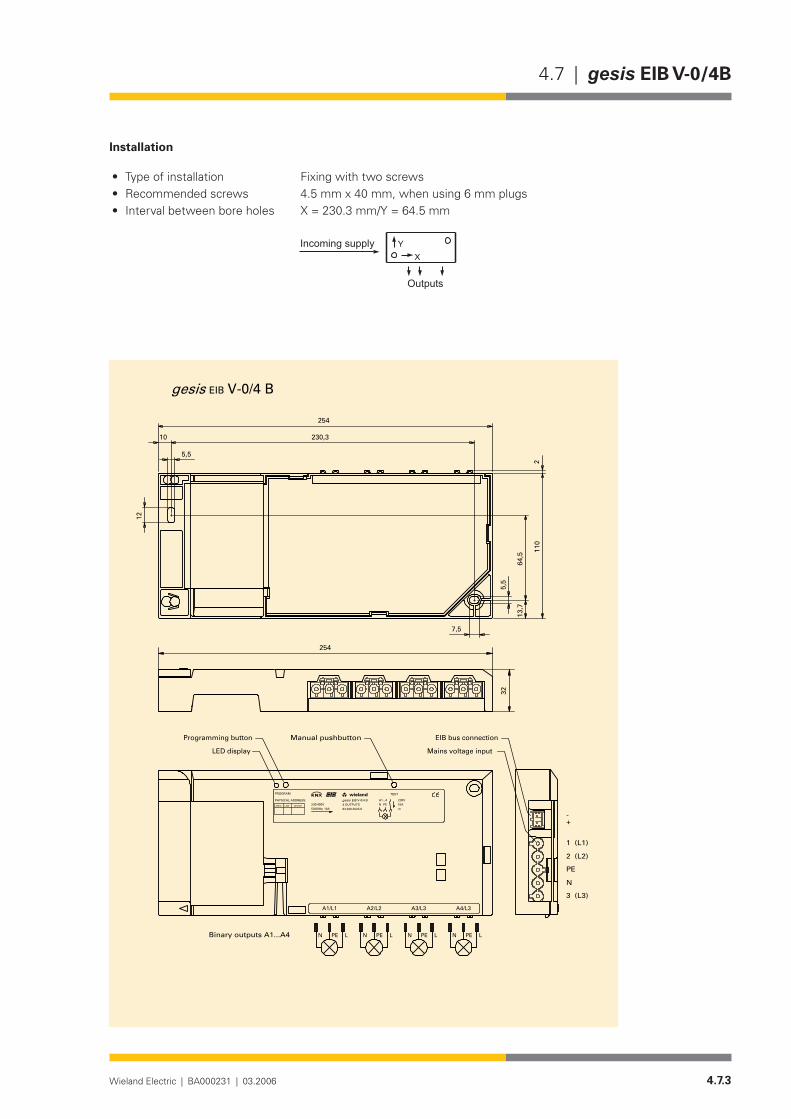
4.7.3Wieland Electric | BA000231 | 03.2006
4.7 | gesis EIB V-0/4B
Installation
Type of installation• Fixing with two screwsRecommended screws • 4.5 mm x 40 mm, when using 6 mm plugsInterval between bore holes• X = 230.3 mm/Y = 64.5 mm
�
����������������
�������
254
110
13,7
64,5
5,5
5,5
10
12
230,3
7,5
2
EIB V-0/4 Bgesis
A1...4PEN
83.020.0225.0
EIB V-0/4 B4 OUTPUTS 16A
m
230V
PE LN PE LN PE LN PE LN
wielandw
gesis
254
32
DEVICELINEAREA
PHYSICAL ADDRESS:
PROGRAM
230/400V50/60Hz; 16A
TEST
A4/L3A3/L3A2/L2A1/L1
Manual pushbutton
1 (L1)
2 (L2)
PE
N
3 (L3)
-+
Binary outputs A1...A4
Mains voltage input
EIB bus connectionProgramming button
LED display

4.7.4 Wieland Electric | BA000231 | 03.2006
gesis EIB V-0/4B | 4.7
Accessories
Accessories for 83.020.0225.0 (gesis EIB V-0/4B)
Incoming supply when using the flat cable system (7 pole)7poleflatcable• 00.702.0323.9EIB adapter• 93.421.0853.0Mains adapter• 92.051.0353.1
Incoming supply via combination connector (EST 2i5)Combination distribution block• 93.550.0053.1Combination connector, female connector• 93.551.0553.1Combination starter cable, female – free end• 94.553.x003.7(x=Lengthinmetres)Combination extension cable, female – male• 94.553.x000.7(x=Lengthinmetres)
Separate incoming supply for mains (GST 18i5) and EIB (BST 14i2)Mains, female connector, screw connection• 92.953.3053.1Mains, starter lead, female – free end• 92.258.x003.1 (x = Length in metres)Mains, extender lead, female – male• 92.258.x000.1 (x = Length in metres)EIB, female connector, spring-loaded connection• 93.421.0553.1EIB, starter lead, female – free end• 94.425.x003.7(x=Lengthinmetres)EIB, extender lead, female – male• 94.425.x000.7(x=Lengthinmetres)
EIB branch (BST 14i2) when using the combination distribution blockEIB, male connector, spring-loaded connection• 93.422.0553.1EIB, starter lead, male – free end• 94.425.x004.7(x=Lengthinmetres)EIB, extender lead, female – male• 94.425.x000.7(x=Lengthinmetres)
Switch outputs (GST 18i3)Male connector, spring-loaded connection• 93.934.0053.1Starter lead, male – free end• 92.232.x004.1 (x = Length in metres)Extender lead, male – female• 92.232.x000.1 (x = Length in metres)
SoftwareProduct database for import in ETS2 •from version V1.1
www.gesis.com (see under Info Service/Download/gesis product database)
Diskette• 00.000.0066.1
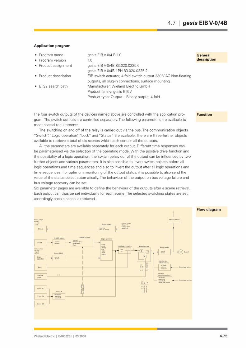
4.7.5Wieland Electric | BA000231 | 03.2006
4.7 | gesis EIB V-0/4B
Application program
Program name• gesis EIB V-0/4 B 1.0Program version• 1.0Product assignment• gesis EIB V-0/4B 83.020.0225.0
gesis EIB V-0/4B 1PH 83.020.0225.2Product description• EIB switch actuator, 4-fold switch output 230 V AC Non-floating
outputs, all plug-in connections, surface mountingETS2 search path• Manufacturer: Wieland Electric GmbH
Product family: gesis EIB V Product type: Output – Binary output, 4-fold
The four switch outputs of the devices named above are controlled with the application pro-gram. The switch outputs are controlled separately. The following parameters are available to meet special requirements.
The switching on and off of the relay is carried out via the bus. The communication objects “Switch”, “Logic operation”, “Lock” and “Status” are available. There are three further objects available to retrieve a total of six scenes which each contain all the outputs.
All the parameters are available separately for each output. Different time responses can be parameterised via the selection of the operating mode. With the positive drive function and the possibility of a logic operation, the switch behaviour of the output can be influenced by two further objects and various parameters. It is also possible to invert switch objects before all logic operations and time sequences and also to invert the output after all logic operations and time sequences. For optimum monitoring of the output status, it is possible to also send the value of the status object automatically. The behaviour of the output on bus voltage failure and bus voltage recovery can be set.Six parameter pages are available to define the behaviour of the outputs after a scene retrieval. Each output can thus be set individually for each scene. The selected switching states are set accordingly once a scene is retrieved.
General description
Function
Flow diagram
���������
���������
���������
����������������������������������
�������������
����
��������������
�����������������
������������������������������������������ ������
�������������������������������
���������
������ �����������������
������������������
�������
������������
�������������
���������
������
����
����
����
���
� ��
�
�����������������
����������
����������������������������������
�����������������������������
�������������������
�����������������������������������������������������
�����������������������������
��������������������
������ ���������������������������
�������������
�������������
�����������������������
������
����
����
����
�����
����
�
�����������������
�������������������������
�����������������������������
���������������������������������
����������������������
����������������������
��
�����
������������������������������������
�����
�����
�
����
����
���
����
�����
����
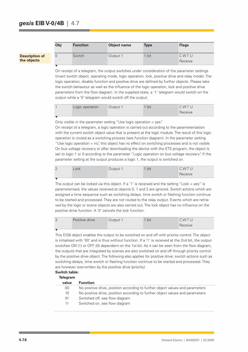
4.7.6 Wieland Electric | BA000231 | 03.2006
gesis EIB V-0/4B | 4.7
Obj Function Object name Type Flags
0 Switch Output 1 1 bit C W T UReceive
On receipt of a telegram, the output switches under consideration of the parameter settings (invert switch object, operating mode, logic operation, lock, positive drive and relay mode). The logic operation, disable function and positive drive are defined by further objects. Please take the switch behaviour as well as the influence of the logic operation, lock and positive drive parameters from the flow diagram. In the supplied state, a ‘1’ telegram would switch on the output while a ‘0’ telegram would switch off the output.
1 Logic operation Output 1 1 bit C W T UReceive
Only visible in the parameter setting “Use logic operation = yes”.On receipt of a telegram, a logic operation is carried out according to the parameterisation with the current switch object value that is present at the logic module. The result of this logic operation is routed as a switching process (see function diagram). In the parameter setting “Use logic operation = no”, this object has no effect on switching processes and is not visible. On bus voltage recovery or after downloading the device with the ETS program, the object is set to logic 1 or 0 according to the parameter “Logic operation on bus voltage recovery”. If the parameter setting at the output produces a logic 1, the output is switched on.
2 Lock Output 1 1 bit C W T UReceive
The output can be locked via this object. If a ‘1’ is received and the setting “Lock = yes” is parameterised, the values received at objects 0, 1 and 2 are ignored. Switch actions which are assigned a time sequence such as switching delays, time switch or flashing function continue to be started and processed. They are not routed to the relay output. Events which are retrie-ved by the logic or scene objects are also carried out. The lock object has no influence on the positive drive function. A ‘0’ cancels the lock function.
3 Positive drive Output 1 1 bit C W T UReceive
This EIS8 object enables the output to be switched on and off with priority control. The object is initialised with ‘00’ and is thus without function. If a ‘1’ is received at the 2nd bit, the output switches ON (1) or OFF (0) dependent on the 1st bit. As it can be seen from the flow diagram, the outputs that are integrated by scenes are also switched on and off through priority control by the positive drive object. The following also applies for positive drive: switch actions such as switching delays, time switch or flashing function continue to be started and processed. They are however overwritten by the positive drive (priority).Switch table:
Telegram value Function
00 No positive drive, position according to further object values and parameters10 No positive drive, position according to further object values and parameters01 Switched off, see flow diagram11 Switched on, see flow diagram
Description of the objects
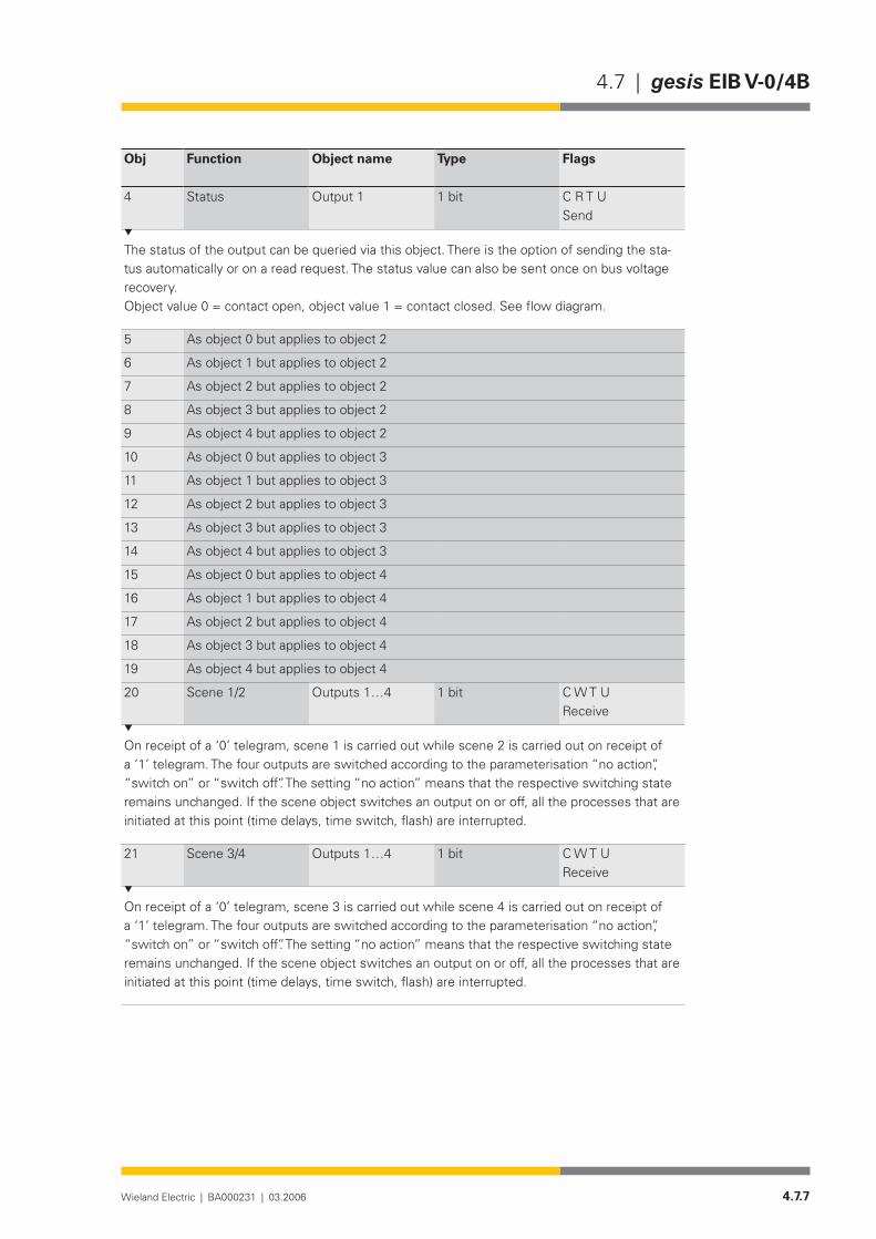
4.7.7Wieland Electric | BA000231 | 03.2006
4.7 | gesis EIB V-0/4B
Obj Function Object name Type Flags
4 Status Output 1 1 bit C R T USend
The status of the output can be queried via this object. There is the option of sending the sta-tus automatically or on a read request. The status value can also be sent once on bus voltage recovery.Object value 0 = contact open, object value 1 = contact closed. See flow diagram.
5 As object 0 but applies to object 2
6 As object 1 but applies to object 2
7 As object 2 but applies to object 2
8 As object 3 but applies to object 2
9 As object 4 but applies to object 2
10 As object 0 but applies to object 3
11 As object 1 but applies to object 3
12 As object 2 but applies to object 3
13 As object 3 but applies to object 3
14 As object 4 but applies to object 3
15 As object 0 but applies to object 4
16 As object 1 but applies to object 4
17 As object 2 but applies to object 4
18 As object 3 but applies to object 4
19 As object 4 but applies to object 4
20 Scene 1/2 Outputs1…4 1 bit C W T UReceive
On receipt of a ‘0’ telegram, scene 1 is carried out while scene 2 is carried out on receipt of a ‘1’ telegram. The four outputs are switched according to the parameterisation “no action”, “switch on” or “switch off”. The setting “no action” means that the respective switching state remains unchanged. If the scene object switches an output on or off, all the processes that are initiated at this point (time delays, time switch, flash) are interrupted.
21 Scene 3/4 Outputs1…4 1 bit C W T UReceive
On receipt of a ‘0’ telegram, scene 3 is carried out while scene 4 is carried out on receipt of a ‘1’ telegram. The four outputs are switched according to the parameterisation “no action”, “switch on” or “switch off”. The setting “no action” means that the respective switching state remains unchanged. If the scene object switches an output on or off, all the processes that are initiated at this point (time delays, time switch, flash) are interrupted.

4.7.8 Wieland Electric | BA000231 | 03.2006
gesis EIB V-0/4B | 4.7
Obj Function Object name Type Flags
22 Scene 5/6 Outputs1…4 1 bit C W T UReceive
On receipt of a ‘0’ telegram, scene 5 is carried out while scene 6 is carried out on receipt of a ‘1’ telegram. The four outputs are switched according to the parameterisation “no action”, “switch on” or “switch off”. The setting “no action” means that the respective switching state remains unchanged. If the scene object switches an output on or off, all the processes that are initiated at this point (time delays, time switch, flash) are interrupted.
The maximum number of addresses and associations is 115.
Parameterisation
Default settings are printed in bold type.Please note that some parameters appear dynamically. These parameters are only visible if
they are required. In the description below, you can recognise this by the comment (only visible for…).Theexplanationsabouttheindividualparametersreferdirectlytothis.Todeterminetheswitch behaviour of the output in advance, it should be noted which other parameters and object values influence the switch behaviour of the output relay.
Please use the flow diagram to obtain a quick overview.
All the parameters are available separately for each output.
Parameters Settings
Operating mode normalON / OFF delaytime switch flash
In all settings, it should be noted which other parameters and object values influence the switch behaviour of the output relay. Please use the flow diagram to obtain a quick overview.The necessary time settings are displayed dynamically.In the operating mode “normal”, the switch command is carried out without a delay or routed in the functional chain.In the operating mode “ON / OFF delay”, the ON/OFF switching processes are carried out with a delay. The ON and OFF switching times are displayed dynamically. If a switching object is received during a delay, the active time sequence is deleted and restarted accordingly. In the operating mode “time switch” (staircase timer function), the output is switched on immediately (‘1’ telegram) and switched off with a delay depending on the parameterisation of the operating time. If a ‘0’ telegram is received, the output is switched off without a delay. If the output is switched on again during the operating time, the time sequence is restarted (retriggered). The total operating time is extended as a result.In the operating mode “flash”, it is possible to switch the output on and off cyclically. This pro-cess is started by a ‘1’ telegram and ended with a ‘0’ telegram.
Output 1 Output 2 Output 3 Output 4

4.7.9Wieland Electric | BA000231 | 03.2006
4.7 | gesis EIB V-0/4B
Parameters Settings
Base for ON delay(only visible in the operating mode “ON / OFF delay”)
20 ms500 ms1 sec1 min1 hr
Factor for ON delay (0-10,000)(only visible in the operating mode “ON / OFF delay”)
10
Period for ON delay = Base x FactorThe factor must be entered as a whole number between 0 and 10000.The parameter “Base for ON delay” and “Factor for ON delay (0-10,000)” define the ON delay of the relay which elapses on receipt of a ‘1’ telegram until the relay is switched on. It should be noted which other parameters and object values influence the switch behaviour of the output relay. Please use the flow diagram to obtain a quick overview.
Base for OFF delay(only visible in the operating mode “ON / OFF delay”)
20 ms500 ms1 sec1 min1 hr
Factor for OFF delay (0-10,000)(only visible in the operating mode “ON / OFF delay”)
10
Period for OFF delay = Base x FactorThe factor must be entered as a whole number between 0 and 10000.The parameter “Base for OFF delay” and “Factor for OFF delay (0-10,000)” define the OFF delay of the relay which elapses on receipt of a ‘1’ telegram until the relay is switched on. It should be noted which other parameters and object values influence the switch behaviour of the output relay. Please use the flow diagram to obtain a quick overview.
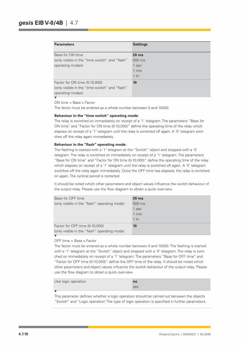
4.7.10 Wieland Electric | BA000231 | 03.2006
gesis EIB V-0/4B | 4.7
Parameters Settings
Base for ON time(only visible in the “time switch” and “flash” operating modes)
20 ms500 ms1 sec1 min1 hr
Factor for ON time (0-10,000)(only visible in the “time switch” and “flash” operating modes)
10
ON time = Base x FactorThe factor must be entered as a whole number between 0 and 10000.
Behaviour in the “time switch” operating mode:The relay is switched on immediately on receipt of a ‘1’ telegram. The parameters “Base for ON time” and “Factor for ON time (0-10,000)” define the operating time of the relay which elapses on receipt of a ‘1’ telegram until the relay is switched off again. A ‘0’ telegram swit-ches off the relay again immediately.
Behaviour in the “flash” operating mode:The flashing is started with a ‘1’ telegram at the “Switch” object and stopped with a ‘0’ telegram. The relay is switched on immediately on receipt of a ‘1’ telegram. The parameters “Base for ON time” and “Factor for ON time (0-10,000)” define the operating time of the relay which elapses on receipt of a ‘1’ telegram until the relay is switched off again. A ‘0’ telegram switches off the relay again immediately. Once the OFF time has elapsed, the relay is switched on again. The cyclical period is restarted.
It should be noted which other parameters and object values influence the switch behaviour of the output relay. Please use the flow diagram to obtain a quick overview.
Base for OFF time(only visible in the “flash” operating mode)
20 ms500 ms1 sec1 min1 hr
Factor for OFF time (0-10,000)(only visible in the “flash” operating mode)
10
OFF time = Base x FactorThe factor must be entered as a whole number between 0 and 10000. The flashing is started with a ‘1’ telegram at the “Switch” object and stopped with a ‘0’ telegram. The relay is swit-ched on immediately on receipt of a ‘1’ telegram. The parameters “Base for OFF time” and “Factor for OFF time (0-10,000)” define the OFF time of the relay. It should be noted which other parameters and object values influence the switch behaviour of the output relay. Please use the flow diagram to obtain a quick overview.
Use logic operation no yes
This parameter defines whether a logic operation should be carried out between the objects “Switch” and “Logic operation”. The type of logic operation is specified in further parameters.
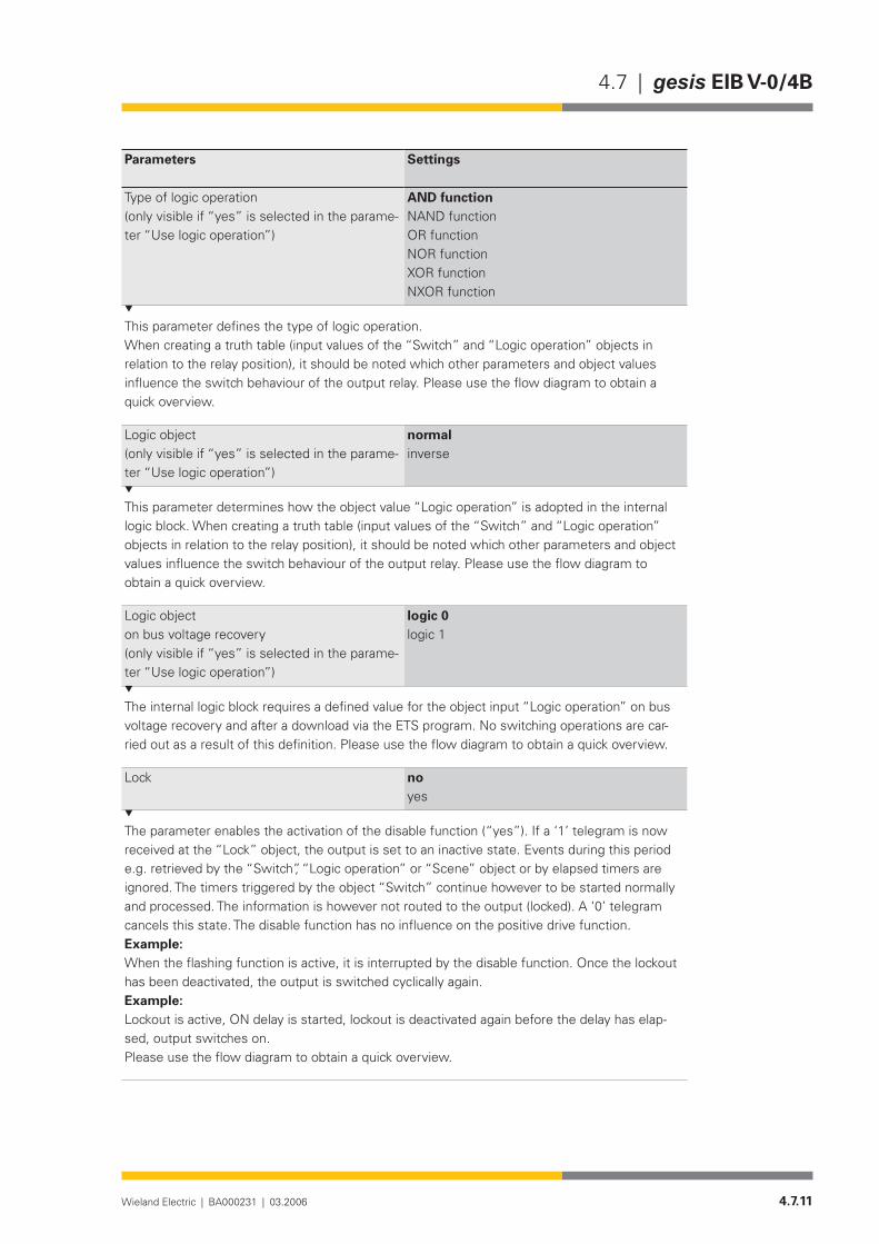
4.7.11Wieland Electric | BA000231 | 03.2006
4.7 | gesis EIB V-0/4B
Parameters Settings
Type of logic operation(only visible if “yes” is selected in the parame-ter “Use logic operation”)
AND functionNAND functionOR functionNOR functionXOR functionNXOR function
This parameter defines the type of logic operation. When creating a truth table (input values of the “Switch” and “Logic operation” objects in relation to the relay position), it should be noted which other parameters and object values influence the switch behaviour of the output relay. Please use the flow diagram to obtain a quick overview.
Logic object(only visible if “yes” is selected in the parame-ter “Use logic operation”)
normalinverse
This parameter determines how the object value “Logic operation” is adopted in the internal logic block. When creating a truth table (input values of the “Switch” and “Logic operation” objects in relation to the relay position), it should be noted which other parameters and object values influence the switch behaviour of the output relay. Please use the flow diagram to obtain a quick overview.
Logic objecton bus voltage recovery(only visible if “yes” is selected in the parame-ter “Use logic operation”)
logic 0logic 1
The internal logic block requires a defined value for the object input “Logic operation” on bus voltage recovery and after a download via the ETS program. No switching operations are car-ried out as a result of this definition. Please use the flow diagram to obtain a quick overview.
Lock noyes
The parameter enables the activation of the disable function (“yes”). If a ‘1’ telegram is now received at the “Lock” object, the output is set to an inactive state. Events during this period e.g. retrieved by the “Switch”, “Logic operation” or “Scene” object or by elapsed timers are ignored. The timers triggered by the object “Switch” continue however to be started normally and processed. The information is however not routed to the output (locked). A ‘0’ telegram cancels this state. The disable function has no influence on the positive drive function.Example: When the flashing function is active, it is interrupted by the disable function. Once the lockout has been deactivated, the output is switched cyclically again.Example: Lockout is active, ON delay is started, lockout is deactivated again before the delay has elap-sed, output switches on.Please use the flow diagram to obtain a quick overview.

4.7.12 Wieland Electric | BA000231 | 03.2006
gesis EIB V-0/4B | 4.7
Parameters Settings
Relay mode normalinverse
The relay mode defines whether the relay output functions as a make contact “relay mode = normal” or as break contact “relay mode = inverse”.Please use the flow diagram to obtain a quick overview.
Switch object normalinverse
This parameter defines whether a telegram at the “Switch” object is routed directly (“normal”) or inverted (“inverse”) for further processing internally.Please use the flow diagram to obtain a quick overview.
Status object read onlysend on change
This parameter defines how the relay status is made available to the bus system. If “read only” is parameterised, the value can only be sent via a read request. If “send on change” is set however, the status is sent automatically after each change.Please use the flow diagram to obtain a quick overview.
Status objecton bus voltage recovery
no actionsend
If “send” is parameterised, the status object is sent once automatically on the bus on bus voltage recovery or after a download via the ETS program.Please use the flow diagram to obtain a quick overview.
Outputon bus voltage recovery
no actionswitch onswitch offset old value
The behaviour of the output on bus voltage recovery or after download via the ETS program is set here. The switching on and off of the output is not dependent on any delays, disable func-tion, logic operation or positive drive function that may have been set. The output is switched immediately.In the setting “set old value”, the output is set to a defined value as before bus voltage failure. This is not the value that is set in the parameterisation “Output on bus voltage failure”.Please use the flow diagram to obtain a quick overview.
Outputon bus voltage failure
no actionswitch onswitch off
The behaviour of the output on bus voltage failure can be set here. The switching on and off of the output is not dependent on any delays, disable function, logic operation or positive drive function that may have been set. The output is switched immediately. It is possible for the modified status to only be sent after bus voltage recovery depending on the setting in the parameter “Status object on bus voltage recovery”.Please use the flow diagram to obtain a quick overview.

4.7.13Wieland Electric | BA000231 | 03.2006
4.7 | gesis EIB V-0/4B
Parameters Settings
All parameters are available separately for each scene
Output 1 no actionswitch onswitch off
Output 2 no actionswitch onswitch off
Output 3 no actionswitch onswitch off
Output 4 no actionswitch onswitch off
All four outputs can be switched on or off simultaneously and independently when a scene is retrieved. In the parameter setting “no action”, the output remains in its current state. The output is switched on and off immediately. Set delay times are ignored. Time sequences that have already been initiated are stopped and reset.Retrieval ofScene 1: ‘0’ telegram at object 20 “Scene 1/2”Scene 2: ‘1’ telegram at object 20 “Scene 1/2”Scene 3: ‘0’ telegram at object 21 “Scene 3/4”Scene 4: ‘1’ telegram at object 21 “Scene 3/4”Scene 5: ‘0’ telegram at object 22 “Scene 5/6”Scene 6: ‘1’ telegram at object 22 “Scene 5/6”
Scene 1 Scene 2 Scene 3 Scene 4 Scene 5 Scene 6

4.7.14 Wieland Electric | BA000231 | 03.2006
gesis EIB V-0/4B | 4.7
4.7.15Wieland Electric | BA000231 | 03.2006
4.7 | gesis EIB V-0/4B 1PH
gesis EIB V-0/4B 1PH
Product description
Designation• Switch actuator, 4-foldType• gesis EIB V-0/4B 1PHPart number• 83.020.0225.2Device type• EIB switch actuator, 4-fold, 230 V AC Non-floating switch
outputs Design• Device with plug-in connections for surface mounting in enc-
losed rooms, fixing on DIN railETS2 application program• gesis EIB V-0/4B 1.0
Function
The switch actuator receives telegrams via the EIB bus and switches via relays four indepen-dent electrical loads with a nominal voltage of 230 V AC. The switch outputs are non-floating. That means that each output is already linked internally with the potentials N, PE and linked with an outer conductor of the mains voltage via a corresponding relay contact. The mains infeed is carried out via a 5 pole mains connector, whereby only pins N, PE and 2 are occupied.
The bus voltage is used to switch the relay on and off.The special function of the device is software-dependent. Various time functions, the behavi-
our on bus voltage failure and bus voltage recovery, disable and priority control functions as well as a logic operation can be implemented via corresponding software settings. The scene control of the outputs is set in the parameterisation and can manage six different scenarios.
The parameterisation and operation of the device requires application software. It is loaded into the device using EIB Tool Software (ETS2).
Functional elements
Programming button• Pressing the programming button switches the programming mode on or off (toggle function).
Manual switch• By repeatedly pressing the switch briefly (< 1 sec), the outputs can be switched on/off in sequence. After a long operation (> 1 sec), the outputs can be switched on/off together.
LED (red)• The red LED indicates the programming status for the physical address.
Technical data
Bus connectionConnection type BST 14i2L male connector, 2 pole, green (EIB coding), (1+/2-)Bus voltage 24 V DC (-4V/+6V)Current consumption approx. 5 mA
Bus connection
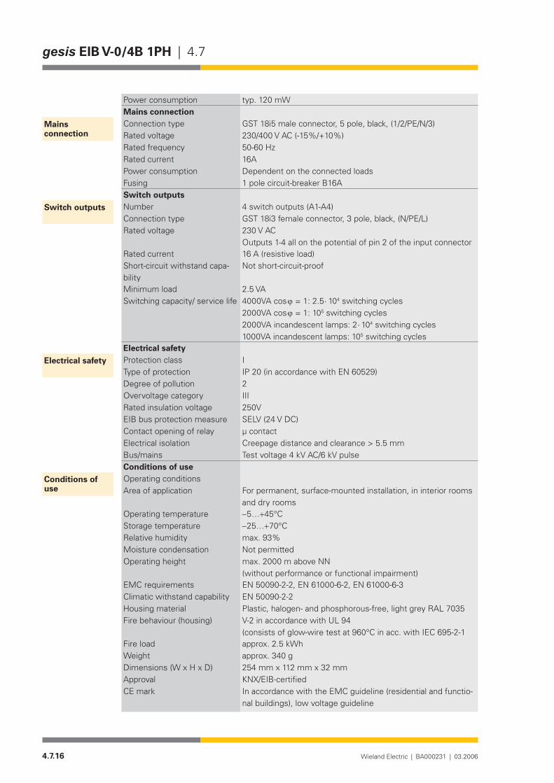
4.7.16 Wieland Electric | BA000231 | 03.2006
gesis EIB V-0/4B 1PH | 4.7
Power consumption typ. 120 mWMains connectionConnection type GST 18i5 male connector, 5 pole, black, (1/2/PE/N/3)Rated voltage 230/400 V AC (-15%/+10%)Rated frequency 50-60 HzRated current 16APower consumption Dependent on the connected loadsFusing 1 pole circuit-breaker B16ASwitch outputsNumber 4 switch outputs (A1-A4)Connection type GST 18i3 female connector, 3 pole, black, (N/PE/L)Rated voltage 230 V AC
Outputs 1-4 all on the potential of pin 2 of the input connectorRated current 16 A (resistive load)Short-circuit withstand capa-bility
Not short-circuit-proof
Minimum load 2.5 VASwitching capacity/ service life 4000VA cos ϕ = 1: 2.5 ⋅ 104 switching cycles
2000VA cos ϕ = 1: 105 switching cycles 2000VA incandescent lamps: 2 ⋅ 104 switching cycles 1000VA incandescent lamps: 105 switching cycles
Electrical safetyProtection class IType of protection IP 20 (in accordance with EN 60529)Degree of pollution 2Overvoltage category IIIRated insulation voltage 250VEIB bus protection measure SELV (24 V DC)Contact opening of relay µ contactElectrical isolation Creepage distance and clearance > 5.5 mmBus/mains Test voltage 4 kV AC/6 kV pulseConditions of useOperating conditionsArea of application For permanent, surface-mounted installation, in interior rooms
and dry roomsOperating temperature −5…+45°CStorage temperature −25…+70°CRelative humidity max. 93%Moisture condensation Not permittedOperating height max. 2000 m above NN
(without performance or functional impairment)EMC requirements EN 50090-2-2, EN 61000-6-2, EN 61000-6-3 Climatic withstand capability EN 50090-2-2Housing material Plastic,halogen-andphosphorous-free,lightgreyRAL7035Fire behaviour (housing) V-2 in accordance with UL 94
(consistsofglow-wiretestat960°Cinacc.withIEC695-2-1Fire load approx. 2.5 kWhWeight approx. 340 gDimensions (W x H x D) 254 mm x 112 mm x 32 mmApproval KNX/EIB-certifiedCE mark In accordance with the EMC guideline (residential and functio-
nal buildings), low voltage guideline
Mains connection
Switch outputs
Electrical safety
Conditions of use

4.7.17Wieland Electric | BA000231 | 03.2006
4.7 | gesis EIB V-0/4B 1PH
Installation
Type of installation• Fixing with two screwsRecommended screws • 4.5 mm x 40 mm, when using 6 mm plugsInterval between bore holes• X = 230.3 mm/Y = 64.5 mm
�
����������������
�������
254
110
13,7
64,5
5,5
5,5
10
12
230,3
7,5
2
EIB V-0/4 B 1PHgesis
A1...4PEN
83.020.0225.2
EIB V-0/4 B 1PH4 OUTPUTS 16A
m
230V
A1 A2 A3 A4
2 (L)
PE
N
-+
PE LN PE LN PE LN PE LNBinary outputs A1...A4
wielandw
gesis
254
32
DEVICELINEAREA
PHYSICAL ADDRESS:
PROGRAM
230V50/60Hz; 16A
TEST
Manual pushbutton
Mains voltage input
EIB bus connectionProgramming button
LED display

4.7.18 Wieland Electric | BA000231 | 03.2006
gesis EIB V-0/4B 1PH | 4.7
Accessories
Accessories for 83.020.0225.0 (gesis EIB V-0/4B)
Incoming supply when using the flat cable system (7 pole)7poleflatcable• 00.702.0323.9EIB adapter• 93.421.0853.0Mains adapter• 92.051.0353.1
Incoming supply via combination connector (EST 2i5)Combination distribution block• 93.550.0053.1Combination connector, female connector• 93.551.0553.1Combination starter cable, female – free end• 94.553.x003.7(x=Lengthinmetres)Combination extension cable, female – male• 94.553.x000.7(x=Lengthinmetres)
Separate incoming supply for mains (GST 18i5) and EIB (BST 14i2)Mains, female connector, screw connection• 92.953.3053.1Mains, starter lead, female – free end• 92.258.x003.1 (x = Length in metres)Mains, extender lead, female – male• 92.258.x000.1 (x = Length in metres)EIB, female connector, spring-loaded connection• 93.421.0553.1EIB, starter lead, female – free end• 94.425.x003.7(x=Lengthinmetres)EIB, extender lead, female – male• 94.425.x000.7(x=Lengthinmetres)
EIB branch (BST 14i2) when using the combination distribution blockEIB, male connector, spring-loaded connection• 93.422.0553.1EIB, starter lead, male – free end• 94.425.x004.7(x=Lengthinmetres)EIB, extender lead, female – male• 94.425.x000.7(x=Lengthinmetres)
Switch outputs (GST 18i3)Male connector, spring-loaded connection• 93.934.0053.1Starter lead, male – free end• 92.232.x004.1 (x = Length in metres)Extender lead, male – female• 92.232.x000.1 (x = Length in metres)
SoftwareProduct database for import in ETS2 •from version V1.1
www.gesis.com (see under Info Service/Download/gesis product database)
Diskette• 00.000.0066.1
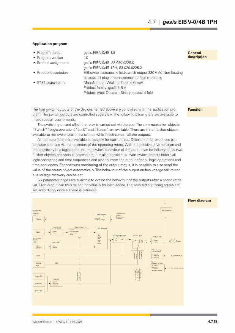
4.7.19Wieland Electric | BA000231 | 03.2006
4.7 | gesis EIB V-0/4B 1PH
Application program
Program name• gesis EIB V-0/4B 1.0Program version• 1.0Product assignment• gesis EIB V-0/4B, 83.020.0225.0
gesis EIB V-0/4B 1PH, 83.020.0225.2Product description• EIB switch actuator, 4-fold switch output 230 V AC Non-floating
outputs, all plug-in connections, surface mounting ETS2 search path• Manufacturer: Wieland Electric GmbH
Product family: gesis EIB V Product type: Output – Binary output, 4-fold
The four switch outputs of the devices named above are controlled with the application pro-gram. The switch outputs are controlled separately. The following parameters are available to meet special requirements.
The switching on and off of the relay is carried out via the bus. The communication objects “Switch”, “Logic operation”, “Lock” and “Status” are available. There are three further objects available to retrieve a total of six scenes which each contain all the outputs.
All the parameters are available separately for each output. Different time responses can be parameterised via the selection of the operating mode. With the positive drive function and the possibility of a logic operation, the switch behaviour of the output can be influenced by two further objects and various parameters. It is also possible to invert switch objects before all logic operations and time sequences and also to invert the output after all logic operations and time sequences. For optimum monitoring of the output status, it is possible to also send the value of the status object automatically. The behaviour of the output on bus voltage failure and bus voltage recovery can be set.
Six parameter pages are available to define the behaviour of the outputs after a scene retrie-val. Each output can thus be set individually for each scene. The selected switching states are set accordingly once a scene is retrieved.
General description
Function
Flow diagram
���������
���������
���������
����������������������������������
�������������
����
��������������
�����������������
������������������������������������������ ������
�������������������������������
���������
������ �����������������
������������������
�������
������������
�������������
���������
������
����
����
����
���
� ��
�
�����������������
����������
����������������������������������
�����������������������������
�������������������
�����������������������������������������������������
�����������������������������
��������������������
������ ���������������������������
�������������
�������������
�����������������������
������
����
����
����
�����
����
�
�����������������
�������������������������
�����������������������������
���������������������������������
����������������������
����������������������
��
�����
������������������������������������
�����
�����
�
����
����
���
����
�����
����

4.7.20 Wieland Electric | BA000231 | 03.2006
gesis EIB V-0/4B 1PH | 4.7
Obj Function Object name Type Flags
0 Switch Output 1 1 bit C W T UReceive
On receipt of a telegram, the output switches under consideration of the parameter settings (invert switch object, operating mode, logic operation, lock, positive drive and relay mode). The logic operation, disable function and positive drive are defined by further objects. Please take the switch behaviour as well as the influence of the logic operation, lock and positive drive parameters from the flow diagram.In the supplied state, a ‘1’ telegram would switch on the output while a ‘0’ telegram would switch off the output.
1 Logic operation Output 1 1 bit C W T UReceive
Only visible in the parameter setting “Use logic operation = yes”.On receipt of a telegram, a logic operation is carried out according to the parameterisation with the current switch object value that is present at the logic module. The result of this logic operation is routed as a switching process (see function diagram). In the parameter setting “Use logic operation = no”, this object has no effect on switching processes and is not visible. On bus voltage recovery or after downloading the device with the ETS program, the object is set to logic 1 or 0 according to the parameter “Logic operation on bus voltage recovery”. If the parameter setting at the output produces a logic 1, the output is switched on.
2 Lock Output 1 1 bit C W T UReceive
The output can be locked via this object. If a ‘1’ is received and the setting “Lock = yes” is parameterised, the values received at objects 0, 1 and 2 are ignored. Switch actions which are assigned a time sequence such as switching delays, time switch or flashing function continue to be started and processed. They are not routed to the relay output. Events which are retrie-ved by the logic or scene objects are also carried out. The lock object has no influence on the positive drive function. A ‘0’ cancels the lock function.
3 Positive drive Output 1 1 bit C W T UReceive
This EIS8 object enables the output to be switched on and off with priority control. The object is initialised with ‘00’ and is thus without function. If a ‘1’ is received at the 2nd bit, the output switches ON (1) or OFF (0) dependent on the 1st bit. As it can be seen from the flow diagram, the outputs that are integrated by scenes are also switched on and off through priority control by the positive drive object. The following also applies for positive drive: switch actions such as switching delays, time switch or flashing function continue to be started and processed. They are however overwritten by the positive drive (priority).Switch table:
Telegram value Function
00 No positive drive, position according to further object values and parameters10 No positive drive, position according to further object values and parameters01 Switched off, see flow diagram11 Switched on, see flow diagram
Description of the objects

4.7.21Wieland Electric | BA000231 | 03.2006
4.7 | gesis EIB V-0/4B 1PH
Obj Function Object name Type Flags
4 Status Output 1 1 bit C R T USend
The status of the output can be queried via this object. There is the option of sending the sta-tus automatically or on a read request. The status value can also be sent once on bus voltage recovery.Object value 0 = contact open, object value 1 = contact closed.See flow diagram.
5 As object 0 but applies to object 2
6 As object 1 but applies to object 2
7 As object 2 but applies to object 2
8 As object 3 but applies to object 2
9 As object 4 but applies to object 2
10 As object 0 but applies to object 3
11 As object 1 but applies to object 3
12 As object 2 but applies to object 3
13 As object 3 but applies to object 3
14 As object 4 but applies to object 3
15 As object 0 but applies to object 4
16 As object 1 but applies to object 4
17 As object 2 but applies to object 4
18 As object 3 but applies to object 4
19 As object 4 but applies to object 4
20 Scene 1/2 Outputs1…4 1 bit C W T UReceive
On receipt of a ‘0’ telegram, scene 1 is carried out while scene 2 is carried out on receipt of a ‘1’ telegram. The four outputs are switched according to the parameterisation “no action”, “switch on” or “switch off”. The setting “no action” means that the respective switching state remains unchanged. If the scene object switches an output on or off, all the processes that are initiated at this point (time delays, time switch, flash) are interrupted.
21 Scene 3/4 Outputs1…4 1 bit C W T UReceive
On receipt of a ‘0’ telegram, scene 3 is carried out while scene 4 is carried out on receipt of a ‘1’ telegram. The four outputs are switched according to the parameterisation “no action”, “switch on” or “switch off”. The setting “no action” means that the respective switching state remains unchanged. If the scene object switches an output on or off, all the processes that are initiated at this point (time delays, time switch, flash) are interrupted.
4.7.22 Wieland Electric | BA000231 | 03.2006
gesis EIB V-0/4B 1PH | 4.7
Obj Function Object name Type Flags
22 Scene 5/6 Outputs1…4 1 bit C W T UReceive
On receipt of a ‘0’ telegram, scene 5 is carried out while scene 6 is carried out on receipt of a ‘1’ telegram. The four outputs are switched according to the parameterisation “no action”, “switch on” or “switch off”. The setting “no action” means that the respective switching state remains unchanged. If the scene object switches an output on or off, all the processes that are initiated at this point (time delays, time switch, flash) are interrupted.
The maximum number of addresses and associations is 115
Parameterisation
Default settings are printed in bold type.Please note that some parameters appear dynamically. These parameters are only visible if they are required. In the description below, you can recognise this by the comment (only visible for…).Theexplanationsabouttheindividualparametersreferdirectlytothis.Todeterminetheswitch behaviour of the output in advance, it should be noted which other parameters and object values influence the switch behaviour of the output relay.
Please use the flow diagram to obtain a quick overview.
All the parameters are available separately for each output
Parameters Settings
Operating mode normalON / OFF delaytime switch flash
In all settings, it should be noted which other parameters and object values influence the switch behaviour of the output relay. Please use the flow diagram to obtain a quick overview.The necessary time settings are displayed dynamically.In the operating mode “normal”, the switch command is carried out without a delay or routed in the functional chain.In the operating mode “ON / OFF delay”, the ON/OFF switching processes are carried out with a delay. The ON and OFF switching times are displayed dynamically. If a switching object is received during a delay, the active time sequence is deleted and restarted accordingly. In the operating mode “time switch” (staircase timer function), the output is switched on immediately (‘1’ telegram) and switched off with a delay depending on the parameterisation of the operating time. If a ‘0’ telegram is received, the output is switched off without a delay. If the output is switched on again during the operating time, the time sequence is restarted (retriggered). The total operating time is extended as a result.In the operating mode “flash”, it is possible to switch the output on and off cyclically. This pro-cess is started by a ‘1’ telegram and ended with a ‘0’ telegram.
Output 1 Output 2 Output 3 Output 4

4.7.23Wieland Electric | BA000231 | 03.2006
4.7 | gesis EIB V-0/4B 1PH
Parameters Settings
Base for ON delay(only visible in the operating mode “ON / OFF delay”)
20 ms500 ms1 sec1 min1 hr
Factor for ON delay (0-10,000)(only visible in the operating mode “ON / OFF delay”)
10
Period for ON delay = Base x FactorThe factor must be entered as a whole number between 0 and 10000.The parameter “Base for ON delay” and “Factor for ON delay (0-10,000)” define the ON delay of the relay which elapses on receipt of a ‘1’ telegram until the relay is switched on. It should be noted which other parameters and object values influence the switch behaviour of the output relay. Please use the flow diagram to obtain a quick overview.
Base for OFF delay(only visible in the operating mode “ON / OFF delay”)
20 ms500 ms1 sec1 min1 hr
Factor for OFF delay (0-10,000)(only visible in the operating mode “ON / OFF delay”)
10
Period for OFF delay = Base x FactorThe factor must be entered as a whole number between 0 and 10000.The parameter “Base for OFF delay” and “Factor for OFF delay (0-10,000)” define the OFF delay of the relay which elapses on receipt of a ‘1’ telegram until the relay is switched on. It should be noted which other parameters and object values influence the switch behaviour of the output relay. Please use the flow diagram to obtain a quick overview.
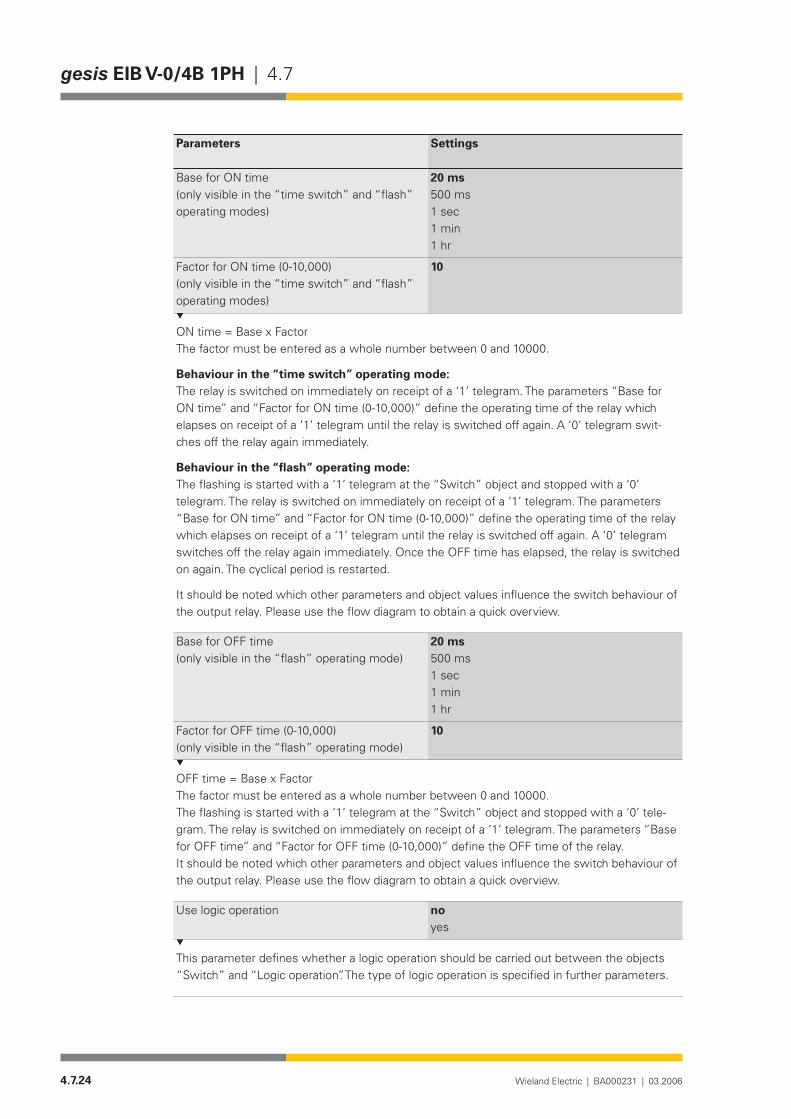
4.7.24 Wieland Electric | BA000231 | 03.2006
gesis EIB V-0/4B 1PH | 4.7
Parameters Settings
Base for ON time(only visible in the “time switch” and “flash” operating modes)
20 ms500 ms1 sec1 min1 hr
Factor for ON time (0-10,000)(only visible in the “time switch” and “flash” operating modes)
10
ON time = Base x FactorThe factor must be entered as a whole number between 0 and 10000.
Behaviour in the “time switch” operating mode:The relay is switched on immediately on receipt of a ‘1’ telegram. The parameters “Base for ON time” and “Factor for ON time (0-10,000)” define the operating time of the relay which elapses on receipt of a ‘1’ telegram until the relay is switched off again. A ‘0’ telegram swit-ches off the relay again immediately.
Behaviour in the “flash” operating mode:The flashing is started with a ‘1’ telegram at the “Switch” object and stopped with a ‘0’ telegram. The relay is switched on immediately on receipt of a ‘1’ telegram. The parameters “Base for ON time” and “Factor for ON time (0-10,000)” define the operating time of the relay which elapses on receipt of a ‘1’ telegram until the relay is switched off again. A ‘0’ telegram switches off the relay again immediately. Once the OFF time has elapsed, the relay is switched on again. The cyclical period is restarted.
It should be noted which other parameters and object values influence the switch behaviour of the output relay. Please use the flow diagram to obtain a quick overview.
Base for OFF time(only visible in the “flash” operating mode)
20 ms500 ms1 sec1 min1 hr
Factor for OFF time (0-10,000)(only visible in the “flash” operating mode)
10
OFF time = Base x FactorThe factor must be entered as a whole number between 0 and 10000.The flashing is started with a ‘1’ telegram at the “Switch” object and stopped with a ‘0’ tele-gram. The relay is switched on immediately on receipt of a ‘1’ telegram. The parameters “Base for OFF time” and “Factor for OFF time (0-10,000)” define the OFF time of the relay.It should be noted which other parameters and object values influence the switch behaviour of the output relay. Please use the flow diagram to obtain a quick overview.
Use logic operation no yes
This parameter defines whether a logic operation should be carried out between the objects “Switch” and “Logic operation”. The type of logic operation is specified in further parameters.

4.7.25Wieland Electric | BA000231 | 03.2006
4.7 | gesis EIB V-0/4B 1PH
Parameters Settings
Type of logic operation(only visible if “yes” is selected in the parame-ter “Use logic operation”)
AND functionNAND functionOR functionNOR functionXOR functionNXOR function
This parameter defines the type of logic operation. When creating a truth table (input values of the “Switch” and “Logic operation” objects in relation to the relay position), it should be noted which other parameters and object values influence the switch behaviour of the output relay. Please use the flow diagram to obtain a quick overview.
Logic object(only visible if “yes” is selected in the parame-ter “Use logic operation”)
normalinverse
This parameter determines how the object value “Logic operation” is adopted in the internal logic block. When creating a truth table (input values of the “Switch” and “Logic operation” objects in relation to the relay position), it should be noted which other parameters and object values influence the switch behaviour of the output relay. Please use the flow diagram to obtain a quick overview.
Logic objecton bus voltage recovery(only visible if “yes” is selected in the parame-ter “Use logic operation”)
logic 0logic 1
The internal logic block requires a defined value for the object input “Logic operation” on bus voltage recovery and after a download via the ETS program. No switching operations are car-ried out as a result of this definition. Please use the flow diagram to obtain a quick overview.
Lock noyes
The parameter enables the activation of the disable function (“yes”). If a ‘1’ telegram is now received at the “Lock” object, the output is set to an inactive state. Events during this period e.g. retrieved by the “Switch”, “Logic operation” or “Scene” object or by elapsed timers are ignored. The timers triggered by the object “Switch” continue however to be started normally and processed. The information is however not routed to the output (locked). A ‘0’ telegram cancels this state. The disable function has no influence on the positive drive function.Example: When the flashing function is active, it is interrupted by the disable function. Once the lockout has been deactivated, the output is switched cyclically again.Example: Lockout is active, ON delay is started, lockout is deactivated again before the delay has elapsed, output switches on.Please use the flow diagram to obtain a quick overview.
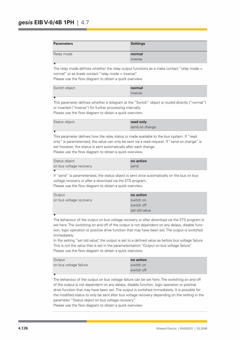
4.7.26 Wieland Electric | BA000231 | 03.2006
gesis EIB V-0/4B 1PH | 4.7
Parameters Settings
Relay mode normalinverse
The relay mode defines whether the relay output functions as a make contact “relay mode = normal” or as break contact “relay mode = inverse”.Please use the flow diagram to obtain a quick overview.
Switch object normalinverse
This parameter defines whether a telegram at the “Switch” object is routed directly (“normal”) or inverted (“inverse”) for further processing internally.Please use the flow diagram to obtain a quick overview.
Status object read onlysend on change
This parameter defines how the relay status is made available to the bus system. If “read only” is parameterised, the value can only be sent via a read request. If “send on change” is set however, the status is sent automatically after each change.Please use the flow diagram to obtain a quick overview.
Status objecton bus voltage recovery
no actionsend
If “send” is parameterised, the status object is sent once automatically on the bus on bus voltage recovery or after a download via the ETS program.Please use the flow diagram to obtain a quick overview.
Outputon bus voltage recovery
no actionswitch onswitch offset old value
The behaviour of the output on bus voltage recovery or after download via the ETS program is set here. The switching on and off of the output is not dependent on any delays, disable func-tion, logic operation or positive drive function that may have been set. The output is switched immediately.In the setting “set old value”, the output is set to a defined value as before bus voltage failure. This is not the value that is set in the parameterisation “Output on bus voltage failure”.Please use the flow diagram to obtain a quick overview.
Outputon bus voltage failure
no actionswitch onswitch off
The behaviour of the output on bus voltage failure can be set here. The switching on and off of the output is not dependent on any delays, disable function, logic operation or positive drive function that may have been set. The output is switched immediately. It is possible for the modified status to only be sent after bus voltage recovery depending on the setting in the parameter “Status object on bus voltage recovery”.Please use the flow diagram to obtain a quick overview.

4.7.27Wieland Electric | BA000231 | 03.2006
4.7 | gesis EIB V-0/4B 1PH
Parameters Settings
All parameters are available separately for each scene
Output 1 no actionswitch onswitch off
Output 2 no actionswitch onswitch off
Output 3 no actionswitch onswitch off
Output 4 no actionswitch onswitch off
All four outputs can be switched on or off simultaneously and independently when a scene is retrieved. In the parameter setting “no action”, the output remains in its current state. The output is switched on and off immediately. Set delay times are ignored. Time sequences that have already been initiated are stopped and reset.Retrieval ofScene 1: ‘0’ telegram at object 20 “Scene 1/2”Scene 2: ‘1’ telegram at object 20 “Scene 1/2”Scene 3: ‘0’ telegram at object 21 “Scene 3/4”Scene 4: ‘1’ telegram at object 21 “Scene 3/4”Scene 5: ‘0’ telegram at object 22 “Scene 5/6”Scene 6: ‘1’ telegram at object 22 “Scene 5/6”
Scene 1 Scene 2 Scene 3 Scene 4 Scene 5 Scene 6

4.7.28 Wieland Electric | BA000231 | 03.2006
4.8.1Wieland Electric | BA000231 | 11.2006
4.8 | gesis EIB V-56/4 (RC)
gesis EIB V-56/4 (RC)
Product
Designation Gateway EnOcean – KNX• Type gesis EIB V-56/4 (RC)• Order number 83.020.0220.0• Device type Gateway• Design Device with plug-in connections • for surface mounting in enclosed roomsETS2 application program gesis EIB V-56/4 (RC) 1.0•
Function
The gateway receives EnOcean telegrams and converts them into KNX telegrams. In addi-tion to the gateway function, the device has four switch outputs which can be controlled independently. The switch outputs are addressed via the KNX and can also be linked with the radio inputs. After the parameterisation, the links between the radio inputs and switch outputs remain fully functional in the event of a bus voltage failure.
The configuration of the inputs and outputs is carried out exclusively by ETS as regards the parameter settings and links on the KNX side. The assignment of the radio-controlled sensors to the gateway is carried out using the learning/deletion mode without requiring further software. The corresponding operating and monitoring elements are located on the front of the gateway.
The EnOcean telegrams of types ORG5 (RPS type 1), ORG6 (1BS) and ORG7 (4BS) must be converted in the KNX. These can be EnOcean push buttons, sensors (e.g. the Wieland alarm transmitter), the EnOcean window contact and similar devices.
On the EnOcean side, up to 170 of these types of links can be stored and distributed among the 56 KNX objects. All the inputs are oriented in pairs i.e. rocker pairs of EnOcean push buttons are always taught in as the upper and lower contact. It is therefore possible to configure the push buttons in toggle mode for dimming applications, for shutter control or for sending values.
Using the high-performance software, the outputs can be controlled with all the usual functions such as time response, behaviour on bus voltage failure and recovery, inverted relay mode and disable function. The status of the relay outputs can be queried or sent automatically.
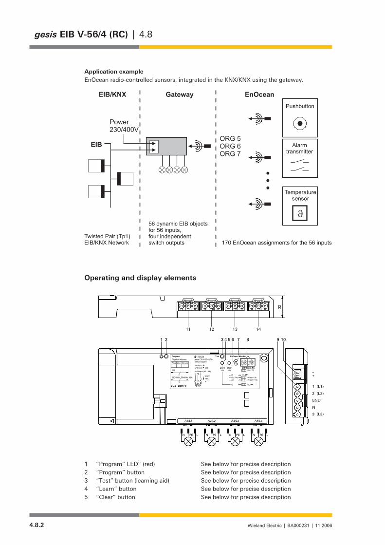
4.8.2 Wieland Electric | BA000231 | 11.2006
gesis EIB V-56/4 (RC) | 4.8
Application exampleEnOcean radio-controlled sensors, integrated in the KNX/KNX using the gateway.
Operating and display elements
254
110
13,7
64,5
5,5
5,5
10
12
230,3
7,5
2
PE LN PE LN PE LN PE LN
32
A4/L3A3/L3A2/L2A1/L1
1 (L1)
2 (L2)
PE
N
3 (L3)
-+2
µ
>3s
ID
All
ID
x
9
ID
x
+ ID5
N
W
L
16A
EIB
Test
x
EIB
gesis
230V
>3s
x
9 + Clear >10s
x = 00...55
Area
Program
PE
Device
Clear
Obj.-No. x + Clear >3s
4x Output (A1...A4)
56x Input RC
Physical Address: EIB V-56/4 (RC)
230/400V, 50/60Hz, 16A
EnOcean Learn
Line83.020.0220.0
wieland EnOcean Monitor
EIB Object-No.
3
90
5
76
01
54
1 2 4 5
2 8
9
1 9
3 74 6
3 6
2 8
7 8 10
11 12 13 14
GND
”Program” LED” (red) See below for precise description1 “Program” button See below for precise description2 “Test” button (learning aid) See below for precise description3 “Learn” button See below for precise description4 “Clear” button See below for precise description5
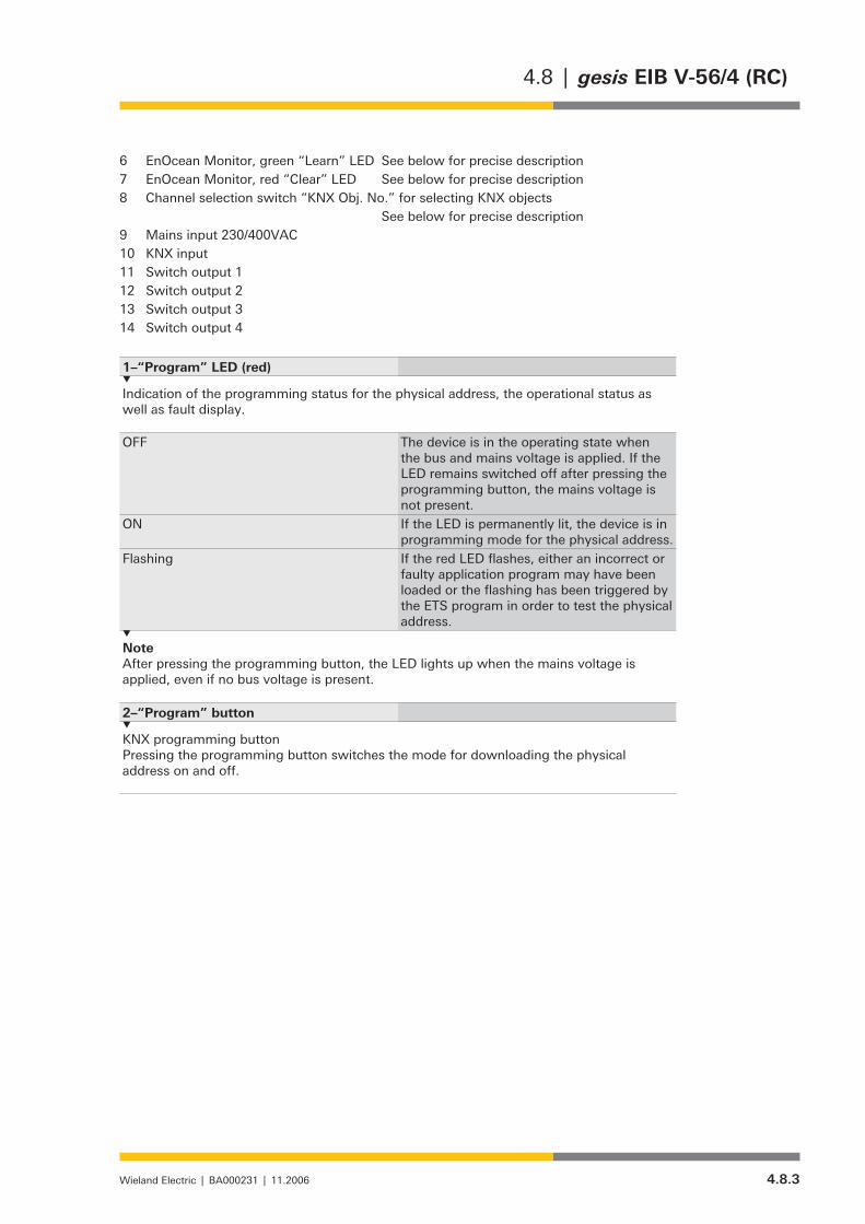
4.8.3Wieland Electric | BA000231 | 11.2006
4.8 | gesis EIB V-56/4 (RC)
EnOcean Monitor, green “Learn” LED See below for precise description6 EnOcean Monitor, red “Clear” LED See below for precise description7 Channel selection switch “KNX Obj. No.” for selecting KNX objects 8 See below for precise descriptionMains input 230/400VAC9 KNX input10 Switch output 111 Switch output 212 Switch output 313 Switch output 414
1–“Program” LED (red)
Indication of the programming status for the physical address, the operational status as well as fault display.
OFF The device is in the operating state when the bus and mains voltage is applied. If the LED remains switched off after pressing the programming button, the mains voltage is not present.
ON If the LED is permanently lit, the device is in programming mode for the physical address.
Flashing If the red LED flashes, either an incorrect or faulty application program may have been loaded or the flashing has been triggered by the ETS program in order to test the physical address.
Note After pressing the programming button, the LED lights up when the mains voltage is applied, even if no bus voltage is present.
2–“Program” button
KNX programming button Pressing the programming button switches the mode for downloading the physical address on and off.

4.8.4 Wieland Electric | BA000231 | 11.2006
gesis EIB V-56/4 (RC) | 4.8
3–“Test” button
The learning aid enables the set object numbers (coding switch) to be checked and thus triggers the appropriate reaction in the KNX network by sending the linked KNX group addresses.
If the parameterisation and linking of the radio-controlled inputs with the KNX objects and switching objects has been concluded and the download of the application from the ETS program to the gateway has been carried out, the function can be tested with this button. The corresponding KNX object is selected with the channel selection switch and the parameterised KNX group address is sent with the “Test” button. It is therefore possible to check whether the correct output is being addressed before teaching in EnOcean sensors.
The “Test” button initiates the sending of telegrams or it switches the outputs.
Test function of the inputs, objects 0 to 55: After each push button action and depending on the parameterisation of the channel or channel pair to be tested, the following telegrams are sent. For switching objects: ON – OFF – ON -- … For dimming objects: ON – dim darker – dim brighter – OFF – ON -- … For shutter objects: UP – stop – DOWN – stop -- UP -- … For value objects: 0 – 1 – 128 – 255 – 0 -- .. The disable object 56 for KNX objects 0-55 has no test function.
Test function of the switch outputs, KNX objects 57 to 65: The switch outputs can likewise be tested. The selected output is switched on and off in toggle mode.
If the channel selection switch is at 57, Output 1 can be tested 59, Output 2 can be tested 61, Output 3 can be tested 63, Output 4 can be tested.
If “Automatic sending” has been parameterised for the status, the modified status is sent. The disable object 65 for outputs 1-4 has no test function. This auxiliary function is always available if existing EnOcean sensors have already been taught into the channel.
4–“Learn” button
EnOcean telegrams can be assigned to the KNX objects in learning mode.
For a detailled description of the learning procedure, please refer to p. 4.8.8, „Brief instruc-tions for commissioning the radio inputs“.
5–“Clear” button
EnOcean telegrams can be deleted from the gateway with the “Clear” button.
For a detailled description of the deleting procedure, please refer to p. 4.8.9, „Brief instruc-tions for deleting radio inputs“.
6 and 7–EnOcean Monitor
This function, represented by a red and a green LED, is used as a commissioning aid. On receipt of an EnOcean telegram, one of the LEDs lights up briefly. It is therefore possible to test whether a transmitter still lies within the range of the gateway.
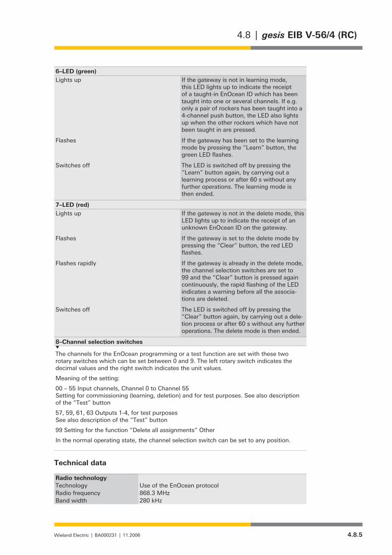
4.8.5Wieland Electric | BA000231 | 11.2006
4.8 | gesis EIB V-56/4 (RC)
6–LED (green)Lights up If the gateway is not in learning mode,
this LED lights up to indicate the receipt of a taught-in EnOcean ID which has been taught into one or several channels. If e.g. only a pair of rockers has been taught into a 4-channel push button, the LED also lights up when the other rockers which have not been taught in are pressed.
Flashes If the gateway has been set to the learning mode by pressing the “Learn” button, the green LED flashes.
Switches off The LED is switched off by pressing the “Learn” button again, by carrying out a learning process or after 60 s without any further operations. The learning mode is then ended.
7–LED (red) Lights up If the gateway is not in the delete mode, this
LED lights up to indicate the receipt of an unknown EnOcean ID on the gateway.
Flashes If the gateway is set to the delete mode by pressing the “Clear” button, the red LED flashes.
Flashes rapidly If the gateway is already in the delete mode, the channel selection switches are set to 99 and the “Clear” button is pressed again continuously, the rapid flashing of the LED indicates a warning before all the associa-tions are deleted.
Switches off The LED is switched off by pressing the “Clear” button again, by carrying out a dele-tion process or after 60 s without any further operations. The delete mode is then ended.
8–Channel selection switches
The channels for the EnOcean programming or a test function are set with these two rotary switches which can be set between 0 and 9. The left rotary switch indicates the decimal values and the right switch indicates the unit values.
Meaning of the setting:
00 – 55 Input channels, Channel 0 to Channel 55 Setting for commissioning (learning, deletion) and for test purposes. See also description of the “Test” button
57, 59, 61, 63 Outputs 1-4, for test purposes See also description of the “Test” button
99 Setting for the function “Delete all assignments” Other
In the normal operating state, the channel selection switch can be set to any position.
Technical data
Radio technologyTechnology Use of the EnOcean protocolRadio frequency 868.3 MHzBand width 280 kHz
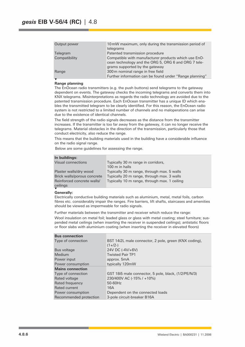
4.8.6 Wieland Electric | BA000231 | 11.2006
gesis EIB V-56/4 (RC) | 4.8
Output power 10 mW maximum, only during the transmission period of telegrams
Telegram Patented transmission procedureCompatibility Compatible with manufacturer products which use EnO-
cean technology and the ORG 5, ORG 6 and ORG 7 tele-grams supported by the gateway
Range 300 m nominal range in free fieldFurther information can be found under “Range planning”
Range planningThe EnOcean radio transmitters (e.g. the push buttons) send telegrams to the gateway dependent on events. The gateway checks the incoming telegrams and converts them into KNX telegrams. Misinterpretations as regards the radio technology are avoided due to the patented transmission procedure. Each EnOcean transmitter has a unique ID which ena-bles the transmitted telegram to be clearly identified. For this reason, the EnOcean radio system is not restricted to a limited number of channels and no maloperations can arise due to the existence of identical channels.The field strength of the radio signals decreases as the distance from the transmitter increases. If the transmitter is too far away from the gateway, it can no longer receive the telegrams. Material obstacles in the direction of the transmission, particularly those that conduct electricity, also reduce the range.This means that the building materials used in the building have a considerable influence on the radio signal range. Below are some guidelines for assessing the range.
In buildings:Visual connections Typically 30 m range in corridors,
100 m in hallsPlaster walls/dry wood Typically 30 m range, through max. 5 wallsBrick walls/porous concrete Typically 20 m range, through max. 3 wallsReinforced concrete walls/ceilings
Typically 10 m range, through max. 1 ceiling
Generally:Electrically conductive building materials such as aluminium, metal, metal foils, carbon fibres etc. considerably impair the ranges. Fire barriers, lift shafts, staircases and amenities should be viewed as impermeable for radio signals.
Further materials between the transmitter and receiver which reduce the range:Wool insulation on metal foil; leaded glass or glass with metal coating; steel furniture; sus-pended metal ceilings (when inserting the receiver in suspended ceilings); antistatic floors or floor slabs with aluminium coating (when inserting the receiver in elevated floors)
Bus connectionType of connection BST 14i2L male connector, 2 pole, green (KNX coding),
(1+/2-)Bus voltage 24V DC (-4V/+6V)Medium Twisted Pair TP1Power input approx. 5mAPower consumption typically 120mW Mains connectionType of connection GST 18i5 male connector, 5 pole, black, (1/2/PE/N/3)Rated voltage 230/400V AC (-15% / +10%)Rated frequency 50-60HzRated current 16APower consumption Dependent on the connected loadsRecommended protection 3-pole circuit-breaker B16A

4.8.7Wieland Electric | BA000231 | 11.2006
4.8 | gesis EIB V-56/4 (RC)
Note: The device can also be connected to an external conductor which is linked with pins 1, 2 and 3 of the incoming connector.
Switch outputsNumber 4 switch outputs (A1-A4)Type of connection GST 18i3 female connector, 3 pole, black, (N/PE/L)Rated voltage 230V AC
Output 1 switches external conductor L1 Output 2 switches external conductor L2 Output 3 switches external conductor L3 Output 4 switches external conductor L3
Rated current 16A (resistive load)Short-circuit withstand capa-bility
not short-circuit-proof
Minimum load 2.5VAMaximum switching currents for 20ms 165A (e.g. incandescent lamps)
for 200µs 800A (e.g. fluorescent lamps with capacitive load)Switching capacity 3000W incandescent lamps = 10000 switching operationsCapacitive load max. 140µF at 230V AC = 20000 switching operations
Note about the loads The contact of the used relay is specifically optimised for switching lamp loads with high inrush currents. The switching of purely resistive loads at a maximum current of 16A is not recommended as the service life of the contact is reduced to approx. 5000 switching operations. The service life is considerably increased with the reduction in the load.
Electrical safetyProtection class IProtection type IP20 (in accordance with EN 60529)Degree of pollution 2Overvoltage category IIIRated insulation voltage 250VKNX bus protection measure SELV (24V DC)Contact opening of relay µ contactOperating conditionsArea of application For permanent surface-mounted installations, in dry interior
roomsAmbient operating temp. -5...+45°CStorage temperature -25...+70°CRelative humidity 5% ... 93%Moisture condensation Not permittedEMC requirements EN 50090-2-2, EN 61000-6-2, EN 61000-6-3, ETS300682Climatic withstand capability EN 50090-2-2Housing material Plastic, halogen- and phosphorous-free, light grey RAL 7035Fire behaviour (housing) V-2 in accordance with UL 94Fire load approx. 3 kWhWeight approx. 480 gDimensions see drawing on p. 4.8.11Approval EIB/KNX certifiedCE mark in accordance with EMC guideline (residential and functio-
nal buildings), low-voltage guideline
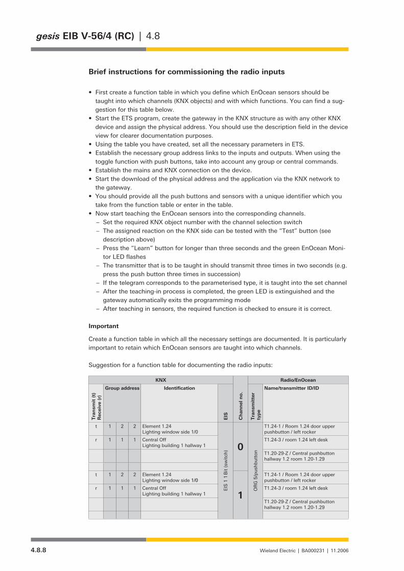
4.8.8 Wieland Electric | BA000231 | 11.2006
gesis EIB V-56/4 (RC) | 4.8
Brief instructions for commissioning the radio inputs
First create a function table in which you define which EnOcean sensors should be • taught into which channels (KNX objects) and with which functions. You can find a sug-gestion for this table below.Start the ETS program, create the gateway in the KNX structure as with any other KNX • device and assign the physical address. You should use the description field in the device view for clearer documentation purposes.Using the table you have created, set all the necessary parameters in ETS.• Establish the necessary group address links to the inputs and outputs. When using the • toggle function with push buttons, take into account any group or central commands.Establish the mains and KNX connection on the device.• Start the download of the physical address and the application via the KNX network to • the gateway.You should provide all the push buttons and sensors with a unique identifier which you • take from the function table or enter in the table.Now start teaching the EnOcean sensors into the corresponding channels.•
Set the required KNX object number with the channel selection switch –The assigned reaction on the KNX side can be tested with the “Test” button (see –description above) Press the “Learn” button for longer than three seconds and the green EnOcean Moni- –tor LED flashesThe transmitter that is to be taught in should transmit three times in two seconds (e.g. –press the push button three times in succession)If the telegram corresponds to the parameterised type, it is taught into the set channel –After the teaching-in process is completed, the green LED is extinguished and the –gateway automatically exits the programming modeAfter teaching in sensors, the required function is checked to ensure it is correct. –
Important
Create a function table in which all the necessary settings are documented. It is particularly important to retain which EnOcean sensors are taught into which channels.
Suggestion for a function table for documenting the radio inputs:
KNX
Chan
nel
no.
Radio/EnOcean
Tra
nsm
it (t)
Rec
eive
(r)
Group address Identification
EIS
Tra
nsm
itte
r ty
pe
Name/transmitter ID/ID
t 1 2 2 Element 1.24Lighting window side 1/0
EIS
1 1
Bit
(sw
itch)
0
OR
G 5
/pus
hbut
ton
T1.24-1 / Room 1.24 door upper pushbutton / left rocker
r 1 1 1 Central OffLighting building 1 hallway 1
T1.24-3 / room 1.24 left desk
T1.20-29-Z / Central pushbutton hallway 1.2 room 1.20-1.29
t 1 2 2 Element 1.24Lighting window side 1/0
1
T1.24-1 / Room 1.24 door upper pushbutton / left rocker
r 1 1 1 Central OffLighting building 1 hallway 1
T1.24-3 / room 1.24 left desk
T1.20-29-Z / Central pushbutton hallway 1.2 room 1.20-1.29

4.8.9Wieland Electric | BA000231 | 11.2006
4.8 | gesis EIB V-56/4 (RC)
Brief instructions for deleting radio inputs
There are three types of deletion:
1. Deletion of an individual ID from the gateway2. Deletion of all IDs from a channel3. Deletion of all IDs from all channels, establishing the supplied state
Explanations about the individual variants:
1. Delete IDs
Ensure that the mains connection on the device has been established.• Press the “Clear” button for longer than three seconds and the red EnOcean Monitor • LED flashes. The ID is deleted from all channels by sending the ID three times. • The red LED is extinguished and the gateway automatically exits the delete mode. • Enter any changes in the function table.•
2. Delete all IDs from a channel
Ensure that the mains connection is established on the device.• Press the “Clear” button for longer than three seconds and the red EnOcean Monitor • LED flashes.Set the channel that is to be deleted using the channel selection switch.• Delete all the IDs from the channel by pressing the “Clear” button again for longer than • three seconds.The red LED is extinguished and the gateway automatically exits the delete mode.• Enter any changes in the function table.•
3. Delete all IDs from the gateway
Ensure that the mains connection is established on the device.• Press the “Clear” button for longer than three seconds and the red EnOcean Monitor • LED lights up.Set the channel selection switch to 99.• Delete all the IDs from the channel by pressing the “Clear” button again for longer than • ten seconds. Before the deletion process is carried out, the red LED starts to flash rapidly as a warning signal.The red LED is extinguished and the gateway automatically exits the delete mode.• Enter any changes in the function table.•
Note:
All deletion processes only affect the radio-related assignments. Any device parameterisa-tion carried out by ETS remains unchanged.

4.8.10 Wieland Electric | BA000231 | 11.2006
gesis EIB V-56/4 (RC) | 4.8
Installation
Type of installation Fixing with two screws• Recommended screws 4.5 mm x 40 mm when using 6 mm plugs• Distance between bore holes X = 230 mm / Y = 64.5 mm•
gesis EIB V-56/4 (RC)
254
110
13,7
64,5
5,5
5,5
10
12
230,3
7,52
EIB V-56/4 (RC)gesis
PE LN PE LN PE LN PE LN
32
A4/L3A3/L3A2/L2A1/L1
1 (L1)
2 (L2)
PE
N
3 (L3)
-+2
µ
>3s
ID
All
ID
x
9
ID
x
+ ID5
N
W
L
16A
EIB
Test
x
EIB
gesis
230V
>3s
x
9 + Clear >10s
x = 00...55
Area
Program
PE
Device
Clear
Obj.-No. x + Clear >3s
4x Output (A1...A4)
56x Input RC
Physical Address: EIB V-56/4 (RC)
230/400V, 50/60Hz, 16A
EnOcean Learn
Line83.020.0220.0
wieland EnOcean Monitor
EIB Object-No.
3
90
5
�6
01
54
1 2 4 5
2 8
9
1 9
3 �4 6
3 6
2 8
7 8 10
11 12 13 14
GND
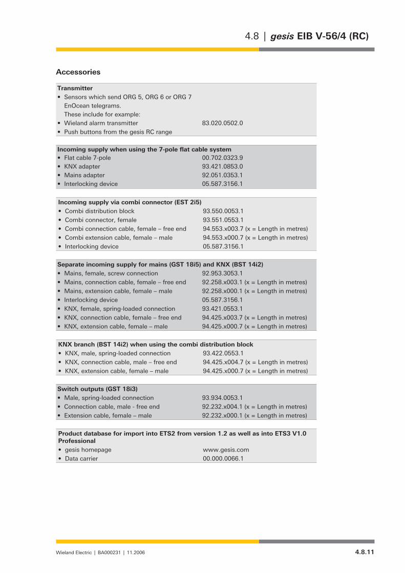
4.8.11Wieland Electric | BA000231 | 11.2006
4.8 | gesis EIB V-56/4 (RC)
Accessories
TransmitterSensors which send ORG 5, ORG 6 or ORG 7 • EnOcean telegrams. These include for example:Wieland alarm transmitter • 83.020.0502.0Push buttons from the gesis RC range •
Incoming supply when using the 7-pole flat cable systemFlat cable 7-pole• 00.702.0323.9KNX adapter• 93.421.0853.0Mains adapter• 92.051.0353.1Interlocking device• 05.587.3156.1
Incoming supply via combi connector (EST 2i5)Combi distribution block• 93.550.0053.1Combi connector, female• 93.551.0553.1Combi connection cable, female – free end• 94.553.x003.7 (x = Length in metres)Combi extension cable, female – male• 94.553.x000.7 (x = Length in metres)Interlocking device• 05.587.3156.1
Separate incoming supply for mains (GST 18i5) and KNX (BST 14i2)Mains, female, screw connection• 92.953.3053.1Mains, connection cable, female – free end• 92.258.x003.1 (x = Length in metres)Mains, extension cable, female – male• 92.258.x000.1 (x = Length in metres)Interlocking device• 05.587.3156.1KNX, female, spring-loaded connection• 93.421.0553.1KNX, connection cable, female – free end• 94.425.x003.7 (x = Length in metres)KNX, extension cable, female – male• 94.425.x000.7 (x = Length in metres)
KNX branch (BST 14i2) when using the combi distribution blockKNX, male, spring-loaded connection• 93.422.0553.1KNX, connection cable, male – free end• 94.425.x004.7 (x = Length in metres)KNX, extension cable, female – male• 94.425.x000.7 (x = Length in metres)
Switch outputs (GST 18i3)Male, spring-loaded connection• 93.934.0053.1Connection cable, male - free end• 92.232.x004.1 (x = Length in metres)Extension cable, female – male• 92.232.x000.1 (x = Length in metres)
Product database for import into ETS2 from version 1.2 as well as into ETS3 V1.0 Professional
gesis homepage • www.gesis.com Data carrier• 00.000.0066.1

4.8.12 Wieland Electric | BA000231 | 11.2006
gesis EIB V-56/4 (RC) | 4.8
Application program
Program name gesis EIB V-56/4 (RC) 1.0• Program version 1.0• Product assignment gesis EIB V-56/4 (RC)• Product description Gateway for integrating EnOcean sensors into the KNX• ETS search path• Manufacturer Wieland Electric• Product family gesis EIB V• Product type Gateway•
The application program manages the 56 EnOcean inputs as well as the four switch out-puts.
The inputs are created in pairs. Depending on the selection of the sensor type and the functionality, the inputs are evaluated separately (e.g. for push buttons in toggle mode) or used in pairs (e.g. push buttons as shutter push buttons). The received telegrams are trans-ferred to the KNX objects and sent according to the set parameters.
A common disable object is available for al the inputs and can be activated via a parame-ter for the respective pair of push buttons.
Using the powerful software, the outputs can be controlled with all the usual parameters such as time response, behaviour on bus voltage failure and recovery, inverted relay mode and a disable function. The disable object is the same for all the outputs but can be evalua-ted separately for each individual output. The status of the relay outputs can be queried or sent automatically.
When uploading the application in the gateway, the application is checked that it is cor-rect. If an incorrect or faulty application is loaded, the red programming LED flashes.
If the bus voltage falls below the permitted voltage value, the parameterised behaviour of the outputs is triggered. If the bus voltage rises again to its specified value, the parame-terised initialisation of the outputs is carried out. This initialisation is also executed by the ETS program on mains voltage recovery and after an upload.
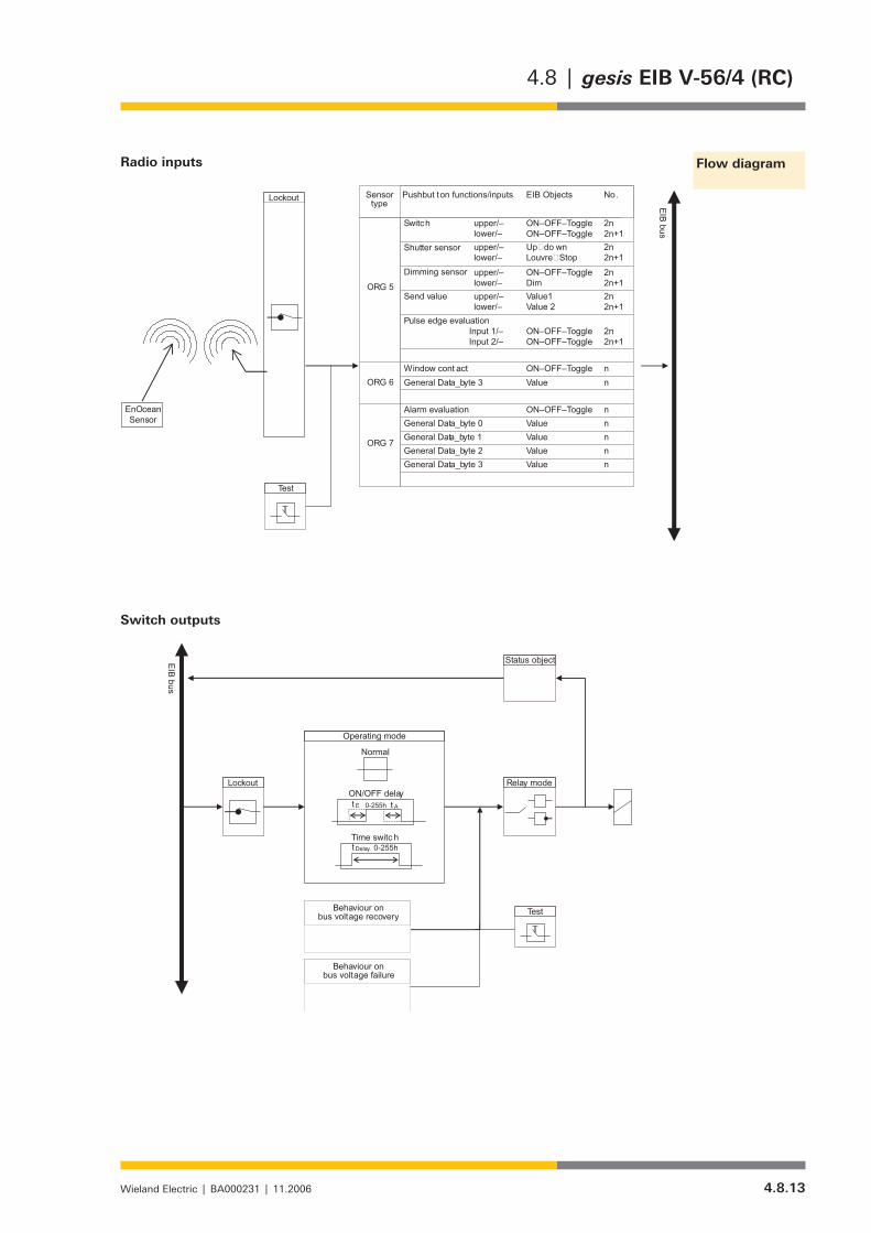
4.8.13Wieland Electric | BA000231 | 11.2006
4.8 | gesis EIB V-56/4 (RC)
Radio inputs
Switch outputs
Flow diagram

4.8.14 Wieland Electric | BA000231 | 11.2006
gesis EIB V-56/4 (RC) | 4.8
Objects description
The objects of the inputs are managed dynamically. For this reason, they appear in the sup-plied state as “Name – Channel x, not used” or “Function – not used”. After defining the sensor type and the function of the inputs, the object name, the object function, the length of the useful information and the necessary flags are shown.
The objects of the switch outputs are static and are already created in the supplied state.The maximum number of group addresses and associations is 234. The maximum number of EnOcean assignments is 170. They can be distributed as required among the inputs.
As regards the inputs, the objects are described in the following section for one pair only. As all 28 pairs can be parameterised separately, all the combinations of the described objects are possible.
Two objects are assigned to each channel pair. The object numbers are
0/1 for the first pair, 2/3 for the second pair,… 54/55 for the 28th pair
Objno.
Parameterised function
Object name
Object function Type EIS Flags Sensor type
0 Push button ORG 5 Switch
Ch. 0, Push button pair 1
Upper contact, ON/OFF/Toggle
1 bit EIS 1 C, W, T, U ORG 5 (push button)
1 Push button ORG 5 Switch
Ch. 1, Push button pair 1
Lower contact, ON/OFF/Toggle
1 bit EIS 1 C, W, T, U ORG 5 (push button)
On receipt of a valid and taught-in EnOcean ORG 5 telegram, the parameterised switching command, ON or OFF, is sent via the linked sending group address. Further group addres-ses that are linked with this object are used for synchronisation if the channel is operating in toggle mode.
0 Push button ORG 5 Shutter sensor
Ch. 0, Push button pair 1
UP/DOWN 1 bit EIS 7 C, T, U ORG 5 (push button)
1 Push button ORG 5 Shutter sensor
Ch. 1, Push button pair 1
Louvres/Stop 1 bit EIS 7 C, T, U ORG 5 (push button)
On receipt of a valid and taught-in EnOcean ORG 5 telegram, the parameterised shutter command is sent to the linked sending group address.
0 Push button ORG 5 Dimming sensor
Ch. 0, Push button pair 1
ON/OFF/Toggle 1 bit EIS 2 C, W, T, U ORG 5 (push button)
1 Push button ORG 5 Dimming sensor
Ch. 1, Push button pair 1
Dim 4 bit EIS 2 C, T, U ORG 5 (push button)
Description of the objects
56 EnOcean inputs
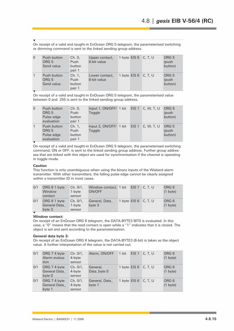
4.8.15Wieland Electric | BA000231 | 11.2006
4.8 | gesis EIB V-56/4 (RC)
On receipt of a valid and taught-in EnOcean ORG 5 telegram, the parameterised switching or dimming command is sent to the linked sending group address.
0 Push button ORG 5 Send value
Ch. 0, Push button pair 1
Upper contact,8-bit value
1 byte EIS 6 C, T, U ORG 5 (push button)
1 Push button ORG 5 Send value
Ch. 1, Push button pair 1
Lower contact,8-bit value
1 byte EIS 6 C, T, U ORG 5 (push button)
On receipt of a valid and taught-in EnOcean ORG 5 telegram, the parameterised value between 0 and 255 is sent to the linked sending group address.
0 Push button ORG 5 Pulse edge evaluation
Ch. 0, Push button pair 1
Input 1, ON/OFF/Toggle
1 bit EIS 1 C, W, T, U ORG 5 (push button)
1 Push button ORG 5 Pulse edge evaluation
Ch. 1, Push button pair 1
Input 2, ON/OFF/Toggle
1 bit EIS 1 C, W, T, U ORG 5 (push button)
On receipt of a valid and taught-in EnOcean ORG 5 telegram, the parameterised switching command, ON or OFF, is sent to the linked sending group address. Further group addres-ses that are linked with this object are used for synchronisation if the channel is operating in toggle mode.
CautionThis function is only unambiguous when using the binary inputs of the Wieland alarm transmitter. With other transmitters, the falling pulse edge cannot be clearly assigned within a transmitter ID in most cases.
0/1 ORG 6 1 byte Window contact
Ch. 0/1, 1-byte sensor
Window contact, ON/OFF
1 bit EIS 1 C, T, U ORG 6 (1 byte)
0/1 ORG 6 1 byte General Data_byte 3.
Ch. 0/1, 1-byte sensor
General, Data_byte 3
1 byte EIS 6 C, T, U ORG 6 (1 byte)
Window contact:On receipt of an EnOcean ORG 6 telegram, the DATA-BYTE3 BIT0 is evaluated. In this case, a “0” means that the reed contact is open while a “1” indicates that it is closed. The object is set and sent according to the parameterisation.
General data byte 3:On receipt of an EnOcean ORG 6 telegram, the DATA-BYTE3 (8-bit) is taken as the object value. A further interpretation of the value is not carried out.
0/1 ORG 7 4 byte Alarm evalua-tion
Ch. 0/1, 4-byte sensor
Alarm, ON/OFF 1 bit EIS 1 C, T, U ORG 6 (1 byte)
0/1 ORG 7 4 byteGeneral Data_byte 0
Ch. 0/1, 4-byte sensor
General, Data_byte 0
1 byte EIS 6 C, T, U ORG 6 (1 byte)
0/1 ORG 7 4 byteGeneral Data_byte 1
Ch. 0/1, 4-byte sensor
General, Data_byte 1
1 byte EIS 6 C, T, U ORG 6 (1 byte)
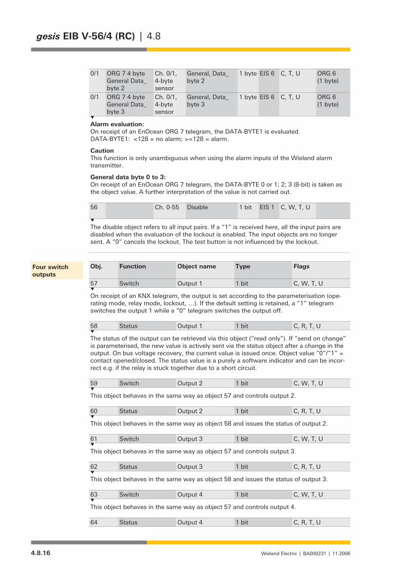
4.8.16 Wieland Electric | BA000231 | 11.2006
gesis EIB V-56/4 (RC) | 4.8
0/1 ORG 7 4 byteGeneral Data_byte 2
Ch. 0/1, 4-byte sensor
General, Data_byte 2
1 byte EIS 6 C, T, U ORG 6 (1 byte)
0/1 ORG 7 4 byteGeneral Data_byte 3
Ch. 0/1, 4-byte sensor
General, Data_byte 3
1 byte EIS 6 C, T, U ORG 6 (1 byte)
Alarm evaluation:On receipt of an EnOcean ORG 7 telegram, the DATA-BYTE1 is evaluated. DATA-BYTE1: <128 = no alarm; >=128 = alarm.
CautionThis function is only unambiguous when using the alarm inputs of the Wieland alarm transmitter.
General data byte 0 to 3:On receipt of an EnOcean ORG 7 telegram, the DATA-BYTE 0 or 1; 2; 3 (8-bit) is taken as the object value. A further interpretation of the value is not carried out.
56 Ch. 0-55 Disable 1 bit EIS 1 C, W, T, U
The disable object refers to all input pairs. If a “1” is received here, all the input pairs are disabled when the evaluation of the lockout is enabled. The input objects are no longer sent. A “0” cancels the lockout. The test button is not influenced by the lockout.
Obj. Function Object name Type Flags
57 Switch Output 1 1 bit C, W, T, U
On receipt of an KNX telegram, the output is set according to the parameterisation (ope-rating mode, relay mode, lockout, …). If the default setting is retained, a “1” telegram switches the output 1 while a “0” telegram switches the output off.
58 Status Output 1 1 bit C, R, T, U
The status of the output can be retrieved via this object (“read only”). If “send on change” is parameterised, the new value is actively sent via the status object after a change in the output. On bus voltage recovery, the current value is issued once. Object value “0”/”1” = contact opened/closed. The status value is a purely a software indicator and can be incor-rect e.g. if the relay is stuck together due to a short circuit.
59 Switch Output 2 1 bit C, W, T, U
This object behaves in the same way as object 57 and controls output 2.
60 Status Output 2 1 bit C, R, T, U
This object behaves in the same way as object 58 and issues the status of output 2.
61 Switch Output 3 1 bit C, W, T, U
This object behaves in the same way as object 57 and controls output 3.
62 Status Output 3 1 bit C, R, T, U
This object behaves in the same way as object 58 and issues the status of output 3.
63 Switch Output 4 1 bit C, W, T, U
This object behaves in the same way as object 57 and controls output 4.
64 Status Output 4 1 bit C, R, T, U
Four switch outputs

4.8.17Wieland Electric | BA000231 | 11.2006
4.8 | gesis EIB V-56/4 (RC)
This object behaves in the same way as object 58 and issues the status of output 4.
65 Lockout Output 1…4 1 bit C, W, T, U
The disable object applies to all four outputs. The disable function can be parameterised separately for each output. If the lockout is activated in an output, the receipt of a “1” at this object prevents the output from carrying out further operations while a “0” cancels the lockout. The test button is not influenced by the lockout.
In the supplied state, a parameter page has been created for each input pair. Further para-meters are displayed after selecting the sensor type. The parameters of a pair of inputs are described in the following section. The parameter sets are identical for all 28 input pairs.
Parameter Settings
Sensor type Not usedPush button (ORG 5)1-byte sensor (ORG 6)4-byte sensor (ORG 7)
This parameter defines which EnOcean sensor type is used.
“Not used” = The input pair is not used. It cannot be taught in.Push button (ORG 5) = A sensor (PTMxxx) with ORG 5 protocol can be taught into the input pair.1-byte sensor (ORG 6) = Two sensors with ORG 6 protocol can be taught into the input pair.4-byte sensor (ORG 7) = Two bytes with ORG 7 protocol can be taught into the input pair.
Further parameters are shown depending on the selection of the sensor type.
Evaluate disable object no yes
The evaluation of the disable object (object no. 56) is defined for the push button pair.
“no” = Value of the disable object is not considered“yes” = Activates the evaluation of the disable object.
If a “1” is received at the disable object, no telegrams are sent to the objects assigned to this push button pair. The objects are updated both by EnOcean telegrams and by any possible KNX telegrams.
After cancelling the lockout with a ‚0‘ telegram at the disable object, the object value will be sent only after another update by an EnOcean telegram.
Long push button action from 0.4 sec0.5 sec0.6 sec0.7 sec0.8 sec1.0 sec1.5 sec2.5 sec
The dividing line between a short and long push button action is defined in this parameter. This distinction is necessary if a blind should be moved e.g. with a long push button action and the blind should be stopped or the louvres adjusted with a short push button action.
Description of the parameters
Channel 0/1 (supplied state)
Sensor type “Push button (ORG 5)”

4.8.18 Wieland Electric | BA000231 | 11.2006
gesis EIB V-56/4 (RC) | 4.8
Function of the push buttons/ inputs SwitchShutter sensorDimming sensorSend valuePulse edge evaluation (only Wieland transmitters)
When selecting the required function, further function-specific parameters and the neces-sary objects are shown. Together with the following parameters, it is finally defined which KNX telegrams are generated after teaching in an EnOcean sensor.
Upper contact(only visible if “Switch” has been selected for “Function of the push buttons/inputs”)
ONOFFTOGGLEshort = ON, long = OFFshort = OFF, long = ONno function
Lower contact(only visible if “Switch” has been selected for “Function of the push buttons/inputs”)
ONOFFTOGGLEshort = ON, long = OFFshort = OFF, long = ONno function
“ON” A push button action sets the input object to “1”“OFF” A push button action sets the input object to “0”“TOGGLE” The current input object is inverted with each push button action.“short = ON, long = OFF” A short push button action sets the input object to “1” while a long pushbutton action sets the input to “0”“short = OFF, long = ON” A long push button action sets the input object to “1” while a short pushbutton action sets the input object to “0”“no function” A push button action has no effect
Upper/lower contact(only visible if “Shutter sensor” has been selected for “Function of the push buttons/inputs”)
UP/DOWNDOWN/UP
This parameter defines which of the rocker contacts triggers the UP or DOWN telegram. This applies both to the assigned object “UP/DOWN” and the object “Louvres/Stop”.
Upper/lower contact(only visible if “Dimming sensor” has been selected for “Function of the push buttons/inputs”)
ON, brighter / OFF, darkerOFF, darker / ON, brighterTOGGLE, brighter / TOGGLE, darkerTOGGLE, darker / TOGGLE, brighter
“ON, brighter / OFF, darker” An ON/OFF telegram is sent to the assigned object “ON/OFF/Toggle” after a shortpush button action. After a long push button action, the dimming command “Dimbrighter/darker by 100%” is issued while a stop telegram is generated when thepush button is released.
“TOGGLE, brighter / TOGGLE, darker”After a short push button action, the device toggles ON/OFF. After a long pushbutton action, the dimming command “Dim brighter/darker by 100%“ is issued while astop telegram is generated when the push button is released.The parameter can also interchange the push button functions.

4.8.19Wieland Electric | BA000231 | 11.2006
4.8 | gesis EIB V-56/4 (RC)
Value of upper contact (0 - 255)(only visible if “Send value” has been selected for “Function of the push buttons/inputs”)
0
Value of lower contact (0 - 255)(only visible if “Send value” has been selected for “Function of the push buttons/inputs”)
0
Each input can send a fixed value (0 – 255) on the KNX.
Input 1(only visible if “Pulse edge evaluation (only Wieland transmitters)“ has been selected for “Function of the push buttons/inputs”)
rising = ON, falling = OFFrising = OFF, falling = ONrising = ONfalling = ONrising = OFFfalling = ONrising = TOGGLEfalling = TOGGLErising = TOGGLE, falling = TOGGLEno evaluationrising = ON, falling = ONrising = OFF, falling = OFFrising = TOGGLE, falling = ONrising = ON, falling = TOGGLErising = OFF, falling = TOGGLErising = TOGGLE, falling = OFF
Input 2(only visible if “Pulse edge evaluation (only Wieland transmitters)“ has been selected for “Function of the push buttons/inputs”)
(see Input 1)
This function is only unambiguous on receipt of telegrams from the Wieland alarm trans-mitter. Other transmitters generate telegrams which cannot always be used for the clear evaluation of the falling pulse edge.
“rising = ON” A rising pulse edge at the input sets the input object to “1” (ON).“falling = OFF” A falling pulse edge sets the input object to “0” (OFF).“rising = TOGGLE” A rising pulse edge inverts the current input object.
All the combinations of falling and rising pulse edge with the reactions ON, OFF or TOGGLE are possible.
Evaluate disable object no yes
The evaluation of the disable object (object no. 56) is defined for the input pair.
“no” = Value of the disable object is not taken into account“yes” = Activates the evaluation of the disable object
If a “1” is received at the disable object, no telegrams are sent to the object that has been assigned to this input pair. The objects are updated both by EnOcean telegrams and by any possible KNX telegrams. The value is however only sent once the lockout has been cancelled with a “0” telegram at the disable object as well as after another update by an EnOcean telegram.
Sensor type “1-byte sensor (ORG 6)”
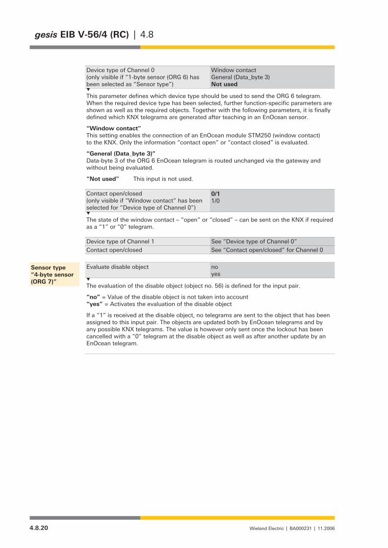
4.8.20 Wieland Electric | BA000231 | 11.2006
gesis EIB V-56/4 (RC) | 4.8
Device type of Channel 0(only visible if “1-byte sensor (ORG 6) has been selected as “Sensor type”)
Window contactGeneral (Data_byte 3)Not used
This parameter defines which device type should be used to send the ORG 6 telegram. When the required device type has been selected, further function-specific parameters are shown as well as the required objects. Together with the following parameters, it is finally defined which KNX telegrams are generated after teaching in an EnOcean sensor.
“Window contact” This setting enables the connection of an EnOcean module STM250 (window contact)to the KNX. Only the information “contact open” or “contact closed” is evaluated.
“General (Data_byte 3)” Data-byte 3 of the ORG 6 EnOcean telegram is routed unchanged via the gateway andwithout being evaluated.
“Not used” This input is not used.
Contact open/closed(only visible if “Window contact” has been selected for “Device type of Channel 0”)
0/11/0
The state of the window contact – “open” or “closed” – can be sent on the KNX if required as a “1” or “0” telegram.
Device type of Channel 1 See “Device type of Channel 0”Contact open/closed See “Contact open/closed” for Channel 0
Evaluate disable object no yes
The evaluation of the disable object (object no. 56) is defined for the input pair.
“no” = Value of the disable object is not taken into account“yes” = Activates the evaluation of the disable object
If a “1” is received at the disable object, no telegrams are sent to the object that has been assigned to this input pair. The objects are updated both by EnOcean telegrams and by any possible KNX telegrams. The value is however only sent once the lockout has been cancelled with a “0” telegram at the disable object as well as after another update by an EnOcean telegram.
Sensor type“4-byte sensor (ORG 7)”

4.8.21Wieland Electric | BA000231 | 11.2006
4.8 | gesis EIB V-56/4 (RC)
Device type of Channel 0(only visible if “4-byte sensor (ORG 7)” has been selected for “Sensor type”)
Alarm evaluation (only Wieland transmitters)General (Data_byte 0)General (Data_byte 1)General (Data_byte 2)General (Data_byte 3)Not used
This parameter defines which device type should be used to send the ORG 6 telegram. When the required device type has been selected, further function-specific parameters are shown as well as the required objects. Together with the following parameters, it is finally defined which KNX telegrams are generated after teaching in an EnOcean sensor.
“Alarm evaluation (only Wieland transmitters)”The parameter enables the connection of the Wieland gesis RC alarm transmitter tothe KNX.
“General (Data_byte 0)”Data-byte 0 of the four data bytes of the ORG 7 EnOcean telegram is sent to theKNX. An interpretation of the data byte by the gateway is not carried out!
“General (Data_byte 1)”: As for data byte 0 only for data byte 1“General (Data_byte 2)”: As for data byte 0 only for data byte 2“General (Data_byte 3)”: As for data byte 0 only for data byte 3
“Not used” This input is not used.
Alarm on/off(only visible if “Alarm evaluation (only Wieland transmitters)” has been selected for “Device type of Channel 0”
0/11/0
The information about the whether the alarm is off or on can be sent as a “0” or “1” on the KNX.
Device type of Channel 1 See “Device type of Channel 0”Alarm on/off See “Alarm on/off” for Channel 0

4.8.22 Wieland Electric | BA000231 | 11.2006
gesis EIB V-56/4 (RC) | 4.8
Each of the four outputs has a separate parameter page. As all the four outputs have exactly the same parameters, only those of Output 1 are explained in the following section.
Parameter page: Output 1
Behaviour on bus voltage recovery no actionswitch onswitch offset old value (value prior to failure)
This parameter determines the behaviour of the output on bus voltage recovery, after an application download or a reset of the microcontroller (the power supply is applied). The switching on and off of the output is not dependent on any delay periods which may have been set or influenced by the lockout. The output is switched immediately.
“no action” The relay is not switched, the contact remains in position.“switch on” If the relay mode is not inverted, the relay is switched on and the output contact is closed. If the relay mode is inverted, the relay is switched off and the output contact is opened.“switch off” If the relay mode is not inverted, the relay is switched off and the output contact is opened. If the relay mode is inverted, the relay is switched on and the output contact is closed.“set old value” The output is set to the value prior to bus voltage failure.
After a download or reset of the microcontroller (the power supply is applied), both the status and the “old” value are set by default to “OFF” (value = 0).
Behaviour on bus voltage failure no actionswitch onswitch off
This parameter determines the behaviour of the output on bus voltage failure. The swit-ching on and off of the output is not dependent on any delay periods which may have been set or influenced by the lockout. The output is switched immediately.
“no action” The relay is not switched, the contact remains in position.“switch on” If the relay mode is not inverted, the relay is switched on and the output contact is closed. If the relay mode is not inverted, the relay is switched off and the output contact is opened.“switch off” If the relay mode is not inverted, the relay is switched off and the output contact is opened. If the relay mode is inverted, the relay is switched on and the output contact is closed.
Status objects are no longer sent on the bus.
Switch outputs
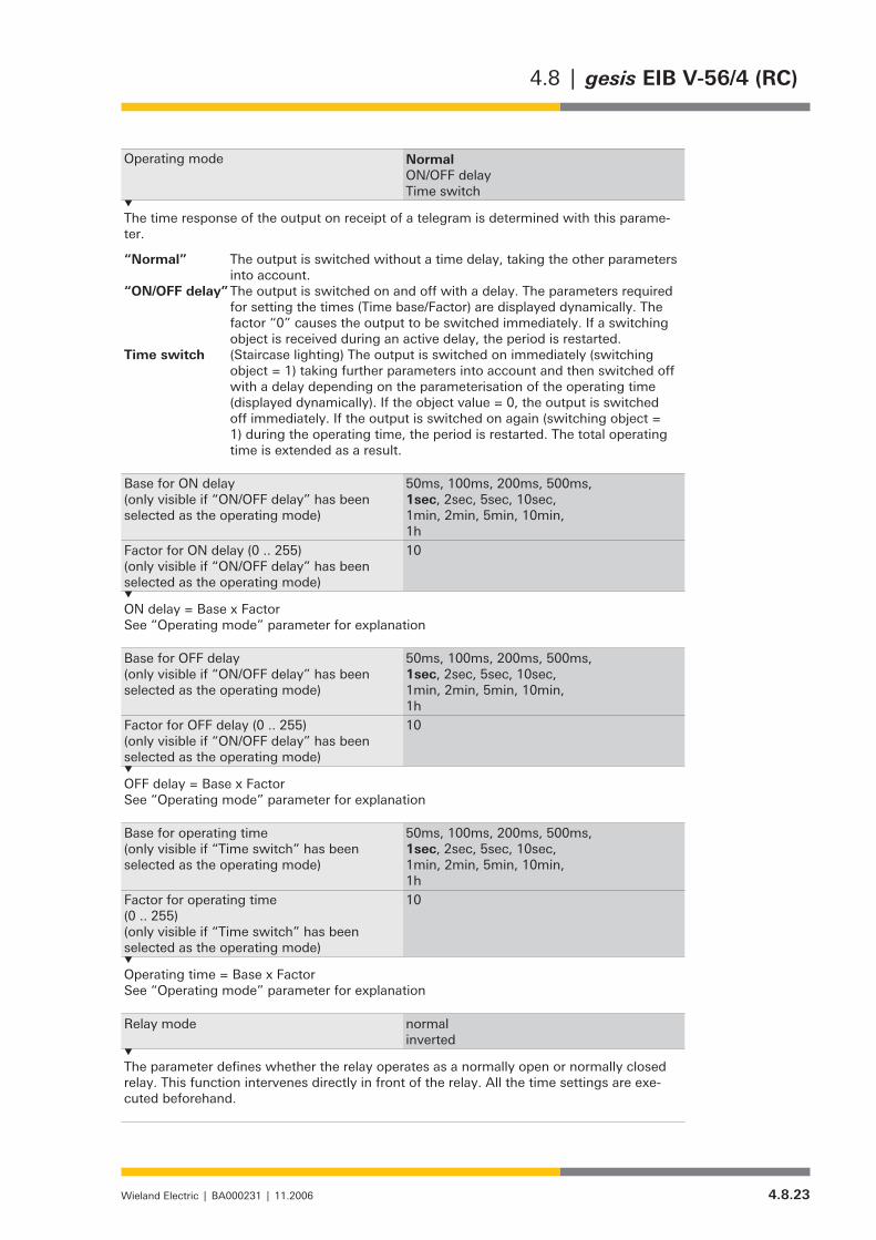
4.8.23Wieland Electric | BA000231 | 11.2006
4.8 | gesis EIB V-56/4 (RC)
Operating mode NormalON/OFF delayTime switch
The time response of the output on receipt of a telegram is determined with this parame-ter.
“Normal” The output is switched without a time delay, taking the other parameters into account. “ON/OFF delay” The output is switched on and off with a delay. The parameters required
for setting the times (Time base/Factor) are displayed dynamically. The factor “0” causes the output to be switched immediately. If a switching object is received during an active delay, the period is restarted.
Time switch (Staircase lighting) The output is switched on immediately (switching object = 1) taking further parameters into account and then switched off with a delay depending on the parameterisation of the operating time (displayed dynamically). If the object value = 0, the output is switched off immediately. If the output is switched on again (switching object = 1) during the operating time, the period is restarted. The total operating time is extended as a result.
Base for ON delay(only visible if “ON/OFF delay” has been selected as the operating mode)
50ms, 100ms, 200ms, 500ms, 1sec, 2sec, 5sec, 10sec, 1min, 2min, 5min, 10min, 1h
Factor for ON delay (0 .. 255)(only visible if “ON/OFF delay” has been selected as the operating mode)
10
ON delay = Base x FactorSee “Operating mode” parameter for explanation
Base for OFF delay(only visible if “ON/OFF delay” has been selected as the operating mode)
50ms, 100ms, 200ms, 500ms, 1sec, 2sec, 5sec, 10sec, 1min, 2min, 5min, 10min, 1h
Factor for OFF delay (0 .. 255)(only visible if “ON/OFF delay” has been selected as the operating mode)
10
OFF delay = Base x FactorSee “Operating mode” parameter for explanation
Base for operating time(only visible if “Time switch” has been selected as the operating mode)
50ms, 100ms, 200ms, 500ms, 1sec, 2sec, 5sec, 10sec, 1min, 2min, 5min, 10min, 1h
Factor for operating time (0 .. 255)(only visible if “Time switch” has been selected as the operating mode)
10
Operating time = Base x FactorSee “Operating mode” parameter for explanation
Relay mode normalinverted
The parameter defines whether the relay operates as a normally open or normally closed relay. This function intervenes directly in front of the relay. All the time settings are exe-cuted beforehand.
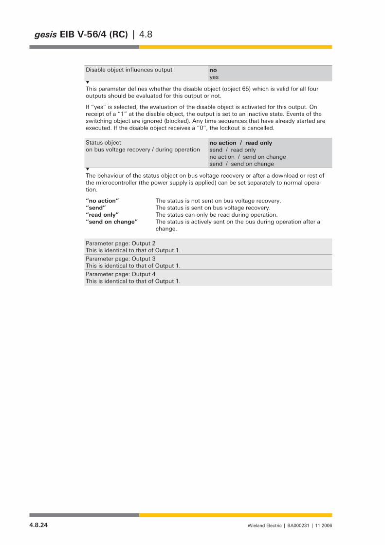
4.8.24 Wieland Electric | BA000231 | 11.2006
gesis EIB V-56/4 (RC) | 4.8
Disable object influences output noyes
This parameter defines whether the disable object (object 65) which is valid for all four outputs should be evaluated for this output or not.
If “yes” is selected, the evaluation of the disable object is activated for this output. On receipt of a “1” at the disable object, the output is set to an inactive state. Events of the switching object are ignored (blocked). Any time sequences that have already started are executed. If the disable object receives a “0”, the lockout is cancelled.
Status objecton bus voltage recovery / during operation
no action / read onlysend / read onlyno action / send on changesend / send on change
The behaviour of the status object on bus voltage recovery or after a download or rest of the microcontroller (the power supply is applied) can be set separately to normal opera-tion.
“no action” The status is not sent on bus voltage recovery.“send” The status is sent on bus voltage recovery.“read only” The status can only be read during operation.“send on change” The status is actively sent on the bus during operation after a
change.
Parameter page: Output 2This is identical to that of Output 1.Parameter page: Output 3This is identical to that of Output 1.Parameter page: Output 4This is identical to that of Output 1.

4.9.1Wieland Electric | BA000231 | 10/2010 (Rev. D)
4.9 | gesis EIB V-0/2W B
gesis EIB V-0/2W B
General Description
Designation• Venetian blind actuator, 2-fold switch outputType• gesis EIB V-0/2W BOrder number• 83.020.0221.0Device type• KNX venetian blind actuator 2-fold switch output
non-floating outputs 230 V AC Design• Device with plug-in connections for surface mounting in closed
rooms, attachment with two screws Mains power connection • 3-phase/5-pin mains power feed-inProgram name• (ETS application program)
gesis EIB V-0/2W B 1.0
Functional Description
The venetian blind actuator receives telegrams from the EIB/KNX bus and switches two inde-pendent drives with two movement directions (e.g. venetian blind motors) via two mutually interlocked relays Both outputs are non-floating. This means that each output is already linked internally with the potentials N, PE and linked with an outer conductor of the mains voltage via the corresponding relay contacts.
Any venetian blind and slats positions can be approached via 8 bit control commands. In doing so, the control here is time-dependent. As the actuator does not receive any unique posi-tion feedback from the controlled drive, the accuracy largely depends on the used motor, the gearbox and the mechanical quality of the venetian blind.
Drives with electromechanical limit switches or with integrated electronics for disconnection at the limit positions can be connected to the outputs. For drives with electromechanical limit switches which provide reverse voltage from the motor, automatic detection of the movement time and synchronisation in the limit positions are performed. It must be ensured that the reverse voltage is within the limits specified in this data sheet.
NOTE:The parallel operation of drives with electromechanical limit switches on one output and mixed operation of the drive types mentioned above on one output are not permitted.
For drives with integrated electronics and for drives which do not provide any reverse voltage, the movement time must be measured as accurately as possible and adjusted in the application program.
However, several decoupled drives using cut-off relays can be controlled as a group. The parameterisation is then performed as for a drive without reverse voltage. Movement times and start positions of the individual drives must be identical for this application.
Time-independent control (only Up/Down/Stop) of a motor is also possible with the actuator.Application software is required for the parameterisation and operation of the device. This software
is loaded into the device using the Engineering Tool Software (ETS).
Drives withelectromechanicallimit switches
Drives with integrated electronics and decoupled drivesusing cut-off relays
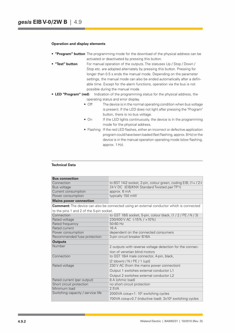
4.9.2 Wieland Electric | BA000231 | 10/2010 (Rev. D)
gesis EIB V-0/2W B | 4.9
Operation and display elements
• "Program" button The programming mode for the download of the physical address can be activated or deactivated by pressing this button.
• "Test" button For manual operation of the outputs. The statuses Up / Stop / Down / Stop etc. are adopted alternately by pressing this button. Pressing for longer than 0.5 s ends the manual mode. Depending on the parameter settings, the manual mode can also be ended automatically after a defin-able time. Except for the alarm functions, operation via the bus is not possible during the manual mode.
• lED "Program" (red) Indication of the programming status for the physical address, the operating status and error display.
• Off Thedeviceisinthenormaloperatingconditionwhenbusvoltageis present. If the LED does not light after pressing the "Program" button, there is no bus voltage.
• On IftheLEDlightscontinuously,thedeviceisintheprogrammingmode for the physical address.
• Flashing IftheredLEDflashes,eitheranincorrectordefectiveapplicationprogram could have been loaded (fast flashing, approx. 8 Hz) or the device is in the manual operation operating mode (slow flashing, approx. 1 Hz).
Technical Data
Bus connectionConnection to BST 14i2 socket, 2-pin, colour green, coding EIB, (1+ / 2-)Bus voltage 24 V DC (EIB/KNX Standard Twisted pair TP1)Current consumption approx. 6 mAPower consumption typically 150 mWMains power connectionComment: The device can also be connected using an external conductor which is connected to the pins 1 and 2 of the 5-pin socket.Connection to GST 18i5 socket, 5-pin, colour black, (1 / 2 / PE / N / 3)Rated voltage 230/400 V AC (-15% / +10%)Rated frequency 50-60 HzRated current 16 APower consumption dependent on the connected consumersRecommended fuse protection 3-pin circuit breaker B16AOutputsNumber 2 outputs with reverse voltage detection for the connec-
tion of venetian blind motorsConnection to GST 18i4 male connector, 4-pin, black,
[2 (down) / N / PE / 1 (up)]Rated voltage 230 V AC (from the mains power connection)
Output 1 switches external conductor L1 Output 2 switches external conductor L2
Rated current (per output) 8 A (ohmic load)Short circuit protection no short circuit protectionMinimum load 2.5 VASwitching capacity / service life 2000 VA cos ϕ=1: 105 switching cycles
700VAcosϕ=0.7(inductiveload):3x10⁵ switching cycles

4.9.3Wieland Electric | BA000231 | 10/2010 (Rev. D)
4.9 | gesis EIB V-0/2W B
Permissible reverse voltage of the connected motors
max. 300 V AC, min. 140 V AC for automatic detection of venetian blind operating time
Cable length at the output for evaluation of the reverse voltage: max. 50 mElectrical safetyProtection class IProtection class IP20 (according to EN 60529)Degree of soiling 2Surge voltage category IIIRated insulation voltage 250 VKNX bus safety precautions SELVContact opening of the relays µ contactOperating conditionsField of application for fixed surface mounting installation in interior and dry areasClimate resistance according to EN 50090-2-2Ambient operating temperature -5-+45°CStorage temperature -25-+70°CRelative humidity 5% - 93%Moisture condensation not permittedEMC requirements EN 50090-2-2, EN 61000-6-2, EN 61000-6-3General dataHousing material Plastic, free of halogens and phosphorous, colour light grey
similartoRAL7035Behaviour in fire (housing) V-2 according to UL 94Thermal load approx. 2.5 kWhWeight approx. 320 gDimensions (W x H x D) 254 mm x 112 mm x 32 mmApproval KNX-certifiedCE certification in accordance with EMC Directive (residential and functional
buildings), Low Voltage Directive
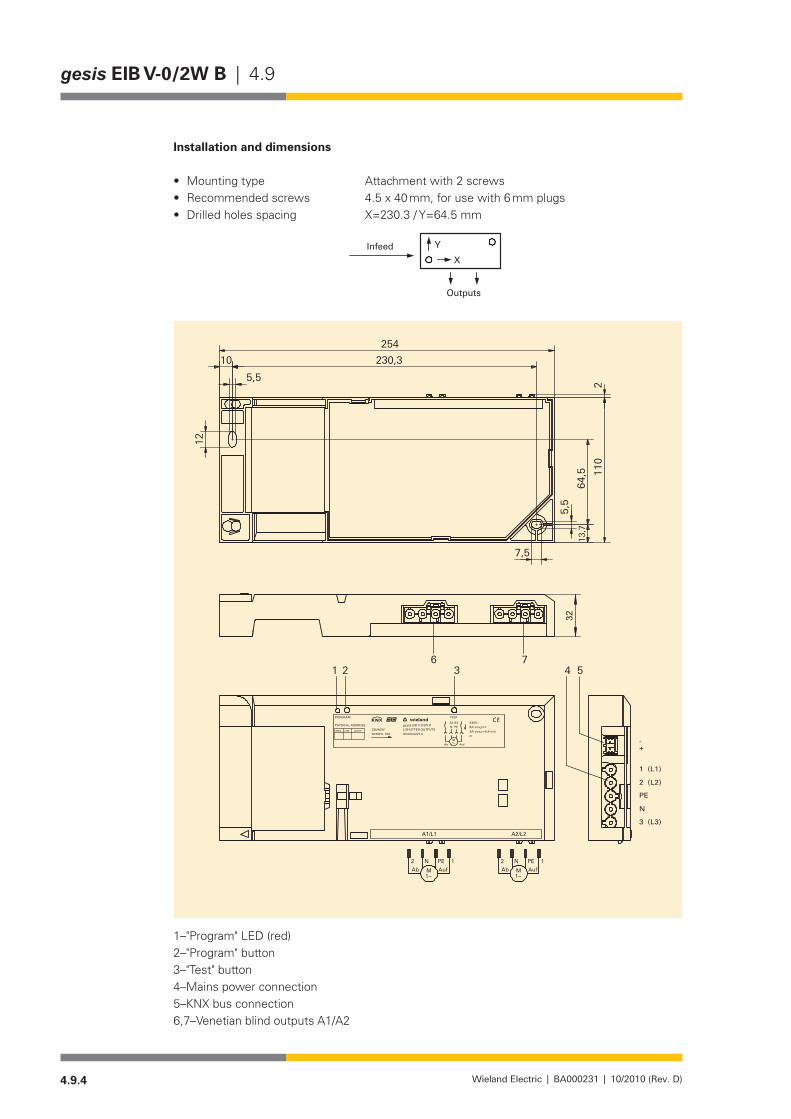
4.9.4 Wieland Electric | BA000231 | 10/2010 (Rev. D)
gesis EIB V-0/2W B | 4.9
Installation and dimensions
Mounting type Attachment with 2 screws•Recommended screws 4.5 x 40 mm, for use with 6 mm plugs•Drilled holes spacing X=230.3 / Y=64.5 mm•
XYInfeed
Outputs
1–"Program" LED (red)2–"Program" button3–"Test" button4–Mains power connection5–KNX bus connection6,7–VenetianblindoutputsA1/A2
4.9.5Wieland Electric | BA000231 | 10/2010 (Rev. D)
4.9 | gesis EIB V-0/2W B
Accessories
Accessories for 83.020.0221.0 (gesis KNX V-0/2W B)
Incoming supply when using the flat cable system (7-pole)7-poleflatcable• 00.702.0323.9EIB Adapter• 93.421.0853.0Mains adapter• 92.051.0353.1Mains adapter/device interlock• 05.587.3156.1
Incoming supply via combination connector (EST 2i5)Combination distribution block• 93.550.0053.1Combination connector, female connector• 93.551.0553.1Combination starter cable, female – free end• 94.553.x003.7(x=lengthinmetres)Combination extension cable, female – male• 94.553.x000.7(x=lengthinmetres)
Separate incoming supply for mains (GST 18i5) and EIB (BST 14i2)Mains, female connector, screw connection• 92.953.3053.1Mains starter lead, female – free end• 92.258.x003.1 (x = length in metres)Mains, extender lead, female – male• 92.258.x000.1 (x = length in metres)EIB, female connector, spring-loaded connection• 93.421.0553.1EIB, starter lead, female – free end• 94.425.x003.7(x=lengthinmetres)EIB, extender lead, female – male• 94.425.x000.7(x=lengthinmetres)
EIB branch (BST 14i2) when using the combination distribution blockEIB, male connector, spring-loaded connection• 93.422.0553.1EIB, starter lead, male – free end• 94.425.x004.7(x=lengthinmetres)EIB, extender lead, female – male• 94.425.x000.7(x=lengthinmetres)
Venetian blind outputs (GST 18i4)Male connector, screw connection• 92.944.3053.1Male connector, spring-loaded connection• 93.944.1053.1Starter lead, male – free end• 92.207.x004.1(x=lengthinmetres)Extender lead, male - female• 92.207.x000.1(x=lengthinmetres)
Product database for import in ETS from version ETS 2 V1.3www.wieland-electric.com• Language selection: English Search term "Product database"

4.9.6 Wieland Electric | BA000231 | 10/2010 (Rev. D)
gesis EIB V-0/2W B | 4.9
Description of the device functions
Venetian blind operating mode
This operating mode is used for actuating sun and anti-glare protection using adjustable angle slatss (e.g. for light deflection). In this operating mode, the venetian blinds can also be ascended and descended, the stop function executed and the slatss of the venetian blinds moved.
Roller blind operating mode
This operating mode is used for the actuation of roller blind, awnings, window and wall cover-ings, gates, doors and windows. Apart from the slats function, the Roller Venetian blind func-tionality is identical to that of the Venetian blind.
Continuous Operation operating mode
Differently from the other two operating modes, no automatic deactivation after a parameter-ised time is performed in this operating mode. Ventilation flaps can be opened and closed in accordance with the requirements in the Heating and Cooling area. This operating mode can also be used for stairway light, actuators or other switching purposes.
The functions can be set separately for each output.
Movement times
Total movement time –
The total movement time is the time needed to move a venetian blind from the "closed" position to the "maximum open" position. A venetian blind is moved in one direction until it
receives a Stop command or until it has reached one of the two end positions (top, bottom) and the motor is deacti-vated via limit switches.
If an end position is detected, the output concerned is also disconnected from the power supply.
If the venetian blind does not have any limit switches, the venetian blind moves in a direction until the actuator receives a Stop command or the total movement time including a parameter-isable run-on time has elapsed.
! In this case, an output is not disconnected from the power supply until after expiry of the total runtime + run-on time!It is also possible to input a value
smaller than 100% for the "Limit position 100%" value. The run-on time is not taken into account here and the limit position is reached according to the parameterised value.
Operating Modes
General Functions
0%
100%
upper endswitch
lower endswitch
Movem
ent up/down
Total movem
ent time
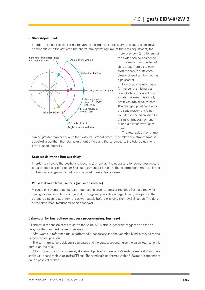
4.9.7Wieland Electric | BA000231 | 10/2010 (Rev. D)
4.9 | gesis EIB V-0/2W B
Slats Adjustment –
In order to adjust the slats angle for venetian blinds, it is necessary to execute short travel commands with the actuator. The shorter the operating time of the slats adjustment, the
more precisely (smaller angle) the slatss can be positioned.
The maximum number of slats steps from slats com-pletely open to slats com-pletely closed can be input as a parameter.
However, a value change for the venetian blind posi-tion which is produced due to a slats movement is initially not taken into account here. The changed position due to the slats movement is not included in the calculation for the new limit position until during a further travel com-mand.
The total adjustment time can be greater than or equal to the "slats adjustment time". If the "slats adjustment time" is selected larger than the total adjustment time using the parameters, the total adjustment time is used internally.
Start-up delay and Run-out delay –
In order to improve the positioning (accuracy) of drives, it is necessary for some gear motors to parameterise a time for an Start-up delay and/or a run-on. These correction times are in the milliseconds range and should only be used in exceptional cases.
Pause between travel actions (pause on reverse) –
A pause on reverse must be parameterised in order to protect the drive from a directly fol-lowing rotation direction change and thus against possible damage. During this pause, the output is disconnected from the power supply before changing the travel direction. The data of the drive manufacturer must be observed.
Behaviour for bus voltage recovery programming, bus reset
All communications objects are set to the value "0". A stop is generally triggered and then a delay for the specified pause on reverse.
Afterwards, a reference run is performed if necessary and the venetian blind is moved to the parameterised position.
The communications objects are updated and the status, depending on the parameterisation, is output on the bus.
After programming or a bus reset, all status objects which are set to "send automatically" and have a valid value send their value to the EIB bus. The sending is performed within 5-20 s and is dependent on the physical address.
Slats total adjustment timefor complete turn Angle on moving up
Status feedback =0
slats adjustmenttime = 0…100%(0/1…255)
Status feedback= 0/1…255
Angle on moving down
255 (fully closed)
0/1 (completely open)
inside outside
4.9.8 Wieland Electric | BA000231 | 10/2010 (Rev. D)
gesis EIB V-0/2W B | 4.9
Bus voltage failure and recovery
The behaviour in the case of bus voltage failure can be parameterised. The reverse on pause is not taken into account for a direction change of the movement.
Safety Functions
All safety functions have priority over all other functions. In the case of several activated safety functions, the priorities of the individual functions can be parameterised via the ETS and thus defined with each other.
lock (1 bit command; "0" = no lock, "1" = lock) –
In the case of a lock, the respective venetian blind is moved to the parameterised position and the operation is locked. When the lock is removed, the output is enabled depending on the other safety functions.
The following commands are executed:
Bit 0 Bit 1 Comment0 0 Operation enabled0 1 Operation enabled1 0 Moving up and locking1 1 Moving down and locking
Venetian blind cleaning, window cleaning / fire alarm (2 bit command) forced control –
When the forced control is deactivated, the output is enabled depending on the other safety functions.
Weather Alarms
All weather alarms (2x wind, 2x rain, 2x frost) function according to the same principle. It can be selected for each output which of the alarms it should react to. Multiple assignments are also possible. The cyclical monitoring of the alarms can be varied according to time or deactivated using parameters. The behaviour of the output in the event of an alarm is defined according to the assignment of the weather alarms to the outputs.
The priority sequence of the three weather alarms (wind, rain, frost) can be parameterised.In the case of revocation of all alarms, the respective output is moved to the parameterised
position (parameter: "Behaviour on reset of weather alarm, locking and forced control").The following applies for all weather alarms: 0 = no alarm, 1 = alarm.
Manual operation mode
For manual operation of the outputs. The statuses Up / Stop / Down / Stop etc. are adopted alternately by pressing this button. Pressing for longer than 0.5 s ends the manual mode. Depending on the parameter settings, the manual mode can also be ended automatically after a definable time. Except for the alarm functions, operation via the bus is not possible during the manual mode.
In the manual mode, the venetian blinds of both outputs are always operated symmetrically (unless one output is locked or there is an activated alarm at an output).
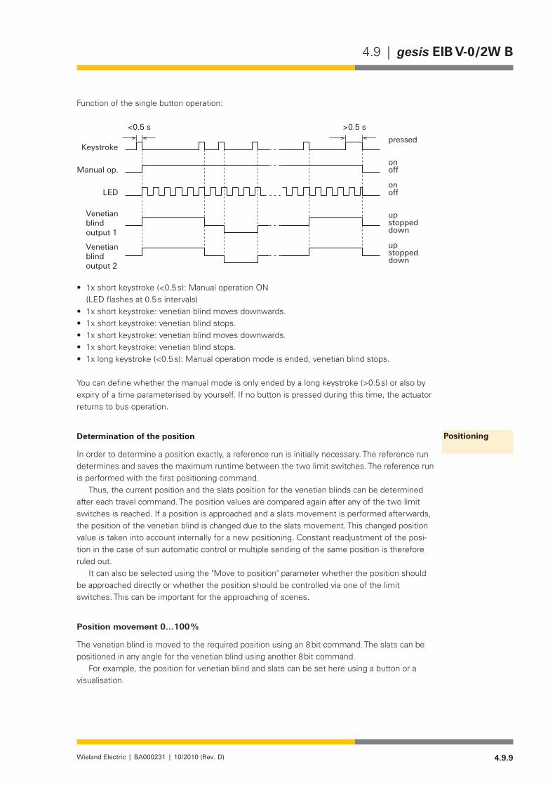
4.9.9Wieland Electric | BA000231 | 10/2010 (Rev. D)
4.9 | gesis EIB V-0/2W B
Function of the single button operation:
<0.5 s >0.5 s
pressed
on
up
up
down
down
stopped
stopped
Keystroke
LED
Manual op.
Venetianblindoutput 1
Venetianblindoutput 2
onoff
off
1x short keystroke (<0.5 s): Manual operation ON •(LED flashes at 0.5 s intervals)1x short keystroke: venetian blind moves downwards.•1x short keystroke: venetian blind stops.•1x short keystroke: venetian blind moves downwards.•1x short keystroke: venetian blind stops.•1x long keystroke (<0.5 s): Manual operation mode is ended, venetian blind stops.•
You can define whether the manual mode is only ended by a long keystroke (>0.5 s) or also by expiry of a time parameterised by yourself. If no button is pressed during this time, the actuator returns to bus operation.
Determination of the position
In order to determine a position exactly, a reference run is initially necessary. The reference run determines and saves the maximum runtime between the two limit switches. The reference run is performed with the first positioning command.
Thus, the current position and the slats position for the venetian blinds can be determined after each travel command. The position values are compared again after any of the two limit switches is reached. If a position is approached and a slats movement is performed afterwards, the position of the venetian blind is changed due to the slats movement. This changed position value is taken into account internally for a new positioning. Constant readjustment of the posi-tion in the case of sun automatic control or multiple sending of the same position is therefore ruled out.
It can also be selected using the "Move to position" parameter whether the position should be approached directly or whether the position should be controlled via one of the limit switches. This can be important for the approaching of scenes.
Position movement 0…100 %
The venetian blind is moved to the required position using an 8 bit command. The slats can be positioned in any angle for the venetian blind using another 8 bit command.
For example, the position for venetian blind and slats can be set here using a button or a visualisation.
Positioning
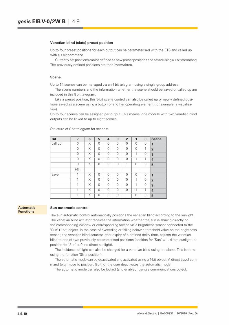
4.9.10 Wieland Electric | BA000231 | 10/2010 (Rev. D)
gesis EIB V-0/2W B | 4.9
Venetian blind (slats) preset position
Up to four preset positions for each output can be parameterised with the ETS and called up with a 1 bit command.
Currently set positions can be defined as new preset positions and saved using a 1 bit command. The previously defined positions are then overwritten.
Scene
Up to 64 scenes can be managed via an 8 bit telegram using a single group address.The scene numbers and the information whether the scene should be saved or called up are
included in this 8 bit telegram.Like a preset position, this 8-bit scene control can also be called up or newly defined posi-
tions saved as a scene using a button or another operating element (for example, a visualisa-tion).Up to four scenes can be assigned per output. This means: one module with two venetian blind outputs can be linked to up to eight scenes.
Structure of 8 bit telegram for scenes:
Bit 7 6 5 4 3 2 1 0 Scenecall up 0 X 0 0 0 0 0 0 1
0 X 0 0 0 0 0 1 20 X 0 0 0 0 1 0 30 X 0 0 0 0 1 1 40 X 0 0 0 1 0 0 5
etc.
save 1 X 0 0 0 0 0 0 11 X 0 0 0 0 1 0 21 X 0 0 0 0 1 0 31 X 0 0 0 0 1 1 41 X 0 0 0 1 0 0 5
Sun automatic control
The sun automatic control automatically positions the venetian blind according to the sunlight. The venetian blind actuator receives the information whether the sun is shining directly on the corresponding window or corresponding façade via a brightness sensor connected to the "Sun" (1-bit) object. In the case of exceeding or falling below a threshold value on the brightness sensor, the venetian blind actuator, after expiry of a defined delay time, adjusts the venetian blind to one of two previously parameterised positions (position for "Sun" = 1, direct sunlight; or position for "Sun" = 0, no direct sunlight).
The incidence of light can also be changed for a venetian blind using the slatss. This is done using the function "Slats position".
The automatic mode can be deactivated and activated using a 1-bit object. A direct travel com-mand (e.g. move to position, 8 bit) of the user deactivates the automatic mode.
The automatic mode can also be locked (and enabled) using a communications object.
Automatic Functions
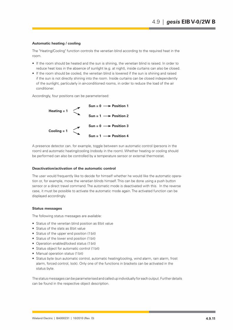
4.9.11Wieland Electric | BA000231 | 10/2010 (Rev. D)
4.9 | gesis EIB V-0/2W B
Automatic heating / cooling
The "Heating/Cooling" function controls the venetian blind according to the required heat in the room.
If the room should be heated and the sun is shining, the venetian blind is raised. In order to •reduce heat loss in the absence of sunlight (e.g. at night), inside curtains can also be closed.If the room should be cooled, the venetian blind is lowered if the sun is shining and raised •if the sun is not directly shining into the room. Inside curtains can be closed independently of the sunlight, particularly in air-conditioned rooms, in order to reduce the load of the air conditioner.
Accordingly, four positions can be parameterised:
Sun = 0 Position 1Heating = 1 Sun = 1 Position 2
Sun = 0 Position 3Cooling = 1 Sun = 1 Position 4
A presence detector can. for example, toggle between sun automatic control (persons in the room) and automatic heating/cooling (nobody in the room). Whether heating or cooling should be performed can also be controlled by a temperature sensor or external thermostat.
Deactivation/activation of the automatic control
The user would frequently like to decide for himself whether he would like the automatic opera-tion or, for example, move the venetian blinds himself. This can be done using a push button sensor or a direct travel command. The automatic mode is deactivated with this. In the reverse case, it must be possible to activate the automatic mode again. The activated function can be displayed accordingly.
Status messages
The following status messages are available:
Status of the venetian blind position as 8 bit value•Status of the slats as 8 bit value•Status of the upper end position (1 bit)•Status of the lower end position (1 bit)•Operation enabled/locked status (1 bit)•Status object for automatic control (1 bit)•Manual operation status (1 bit)•Status byte (sun automatic control, automatic heating/cooling, wind alarm, rain alarm, frost •alarm, forced control, lock). Only one of the functions in brackets can be activated in the status byte.
The status messages can be parameterised and called up individually for each output. Further details can be found in the respective object description.

4.9.12 Wieland Electric | BA000231 | 10/2010 (Rev. D)
gesis EIB V-0/2W B | 4.9
Application Program
Program name• gesis EIB V-0/2W BProgram version• 1.0Product allocation• gesis EIB V-0/2W B 83.020.0221.0
gesis EIB V-0/2W B SP 83.020.0221.4Source of supply• www.gesis.com
Info Service/Download/gesis ProduktdatenbankProduct Description• EIB venetian blind actuator 2-fold switch output (230 V AC)
Non-floating outputs,all plug-in connections, surface mounting
Manufacturer•Product series•Product type•
Wieland Electric GmbH gesis EIB V Venetian blind
The application program enables simple and complex venetian blind controls, roller blind con-trols and also makes it possible to activate the outputs in continuous operation. Both the com-munications objects as well as the parameters are dynamically displayed and hidden depending on the parameter selection. A simple venetian blind control with four objects is available in the default settings. This can be extended using the parameter settings to a complex venetian blind system with up to 65 communications objects (operating mode "Venetian blind").
Possible Operating Modes maximum number of communications objects
Venetian blind 65
Roller blind 60Continuous operation 23
These communications objects can be subdivided into groups:Alarms and manual operation •Seven objects which can be created in every operating mode and can be used jointly by the outputs A/B
Direct Communications Objects •Eleven objects per output. These are objects which should not be used by the venetian blind actuation. For example, this includes a travel command from a button. The automation can be deactivated using these objects depending on the parameter settings.
Automatic Communications Objects •Nine objects per output. These are objects which are used by sensors or by central automa-tion equipment. The objective of these controls is frequently energy saving depending on time, weather, climate values and the presence of persons.
Safety Communications Objects •Six common objects for outputs A/B plus two per output. These are the already described alarm objects and the two objects for lock and forced control per channel.
Status or feedback objects •One general object plus seven objects per channel. Using these objects, various status values of the venetian blinds and the operating statuses can be retrieved. Some of the status messages can also be sent automatically from the actuator to the bus if required.
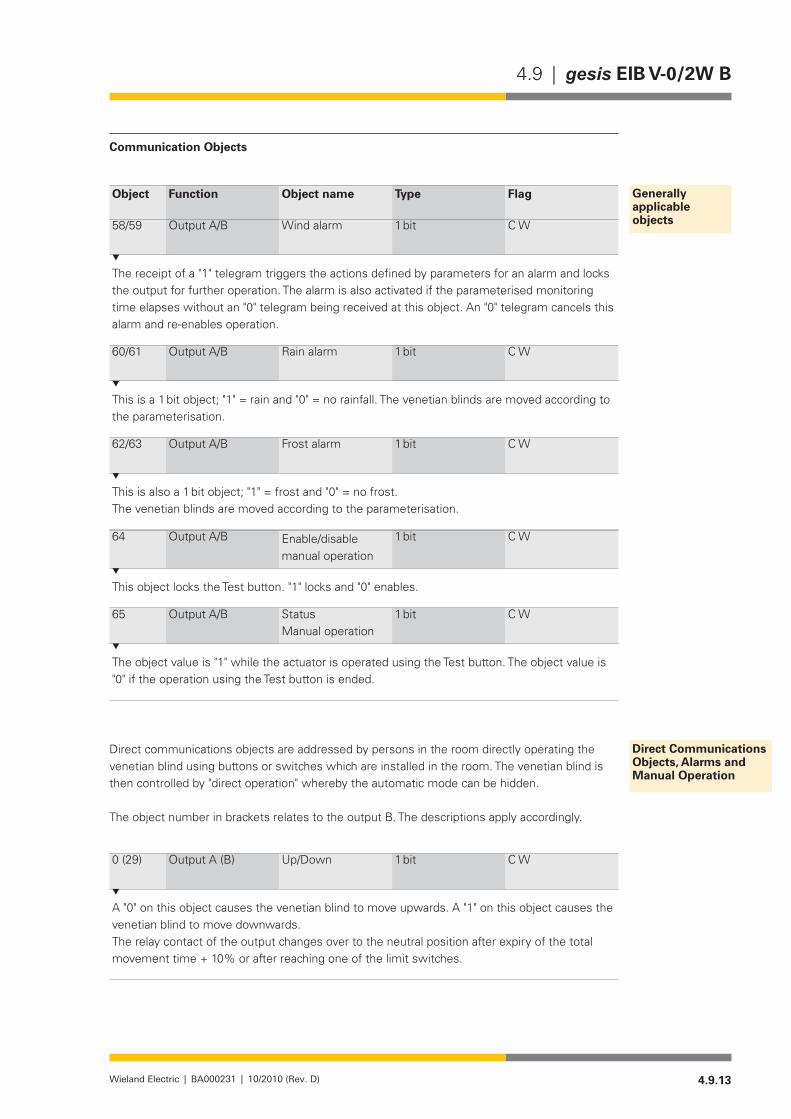
4.9.13Wieland Electric | BA000231 | 10/2010 (Rev. D)
4.9 | gesis EIB V-0/2W B
Communication Objects
Object Function Object name Type Flag
58/59 Output A/B Wind alarm 1 bit C W
The receipt of a "1" telegram triggers the actions defined by parameters for an alarm and locks the output for further operation. The alarm is also activated if the parameterised monitoring time elapses without an "0" telegram being received at this object. An "0" telegram cancels this alarm and re-enables operation.
60/61 Output A/B Rain alarm 1 bit C W
This is a 1 bit object; "1" = rain and "0" = no rainfall. The venetian blinds are moved according to the parameterisation.
62/63 Output A/B Frost alarm 1 bit C W
This is also a 1 bit object; "1" = frost and "0" = no frost.The venetian blinds are moved according to the parameterisation.
64 Output A/B Enable/disable manual operation
1 bit C W
This object locks the Test button. "1" locks and "0" enables.
65 Output A/B Status Manual operation
1 bit C W
The object value is "1" while the actuator is operated using the Test button. The object value is "0" if the operation using the Test button is ended.
Direct communications objects are addressed by persons in the room directly operating the venetian blind using buttons or switches which are installed in the room. The venetian blind is then controlled by "direct operation" whereby the automatic mode can be hidden.
The object number in brackets relates to the output B. The descriptions apply accordingly.
0 (29) Output A (B) Up/Down 1 bit C W
A "0" on this object causes the venetian blind to move upwards. A "1" on this object causes the venetian blind to move downwards.The relay contact of the output changes over to the neutral position after expiry of the total movement time + 10% or after reaching one of the limit switches.
Generally applicable objects
Direct Communications Objects, Alarms and Manual Operation
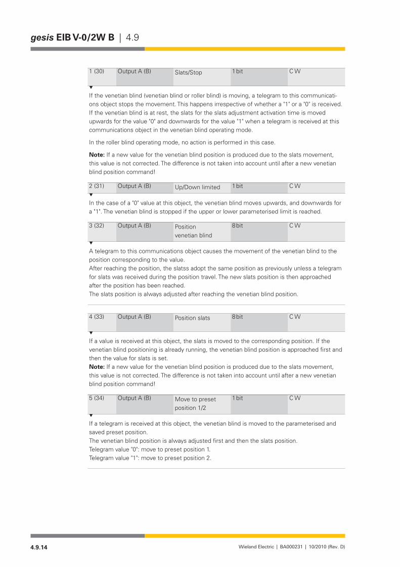
4.9.14 Wieland Electric | BA000231 | 10/2010 (Rev. D)
gesis EIB V-0/2W B | 4.9
1 (30) Output A (B) Slats/Stop 1 bit C W
If the venetian blind (venetian blind or roller blind) is moving, a telegram to this communicati-ons object stops the movement. This happens irrespective of whether a "1" or a "0" is received. If the venetian blind is at rest, the slats for the slats adjustment activation time is moved upwards for the value "0" and downwards for the value "1" when a telegram is received at this communications object in the venetian blind operating mode.
In the roller blind operating mode, no action is performed in this case.
Note: If a new value for the venetian blind position is produced due to the slats movement, this value is not corrected. The difference is not taken into account until after a new venetian blind position command!
2 (31) Output A (B) Up/Down limited 1 bit C W
In the case of a "0" value at this object, the venetian blind moves upwards, and downwards for a "1". The venetian blind is stopped if the upper or lower parameterised limit is reached.
3 (32) Output A (B) Position venetian blind
8 bit C W
A telegram to this communications object causes the movement of the venetian blind to the position corresponding to the value.After reaching the position, the slatss adopt the same position as previously unless a telegram for slats was received during the position travel. The new slats position is then approached after the position has been reached.The slats position is always adjusted after reaching the venetian blind position.
4 (33) Output A (B) Position slats 8 bit C W
If a value is received at this object, the slats is moved to the corresponding position. If the venetian blind positioning is already running, the venetian blind position is approached first and then the value for slats is set.Note: If a new value for the venetian blind position is produced due to the slats movement, this value is not corrected. The difference is not taken into account until after a new venetian blind position command!
5 (34) Output A (B) Move to preset position 1/2
1 bit C W
If a telegram is received at this object, the venetian blind is moved to the parameterised and saved preset position.The venetian blind position is always adjusted first and then the slats position.Telegram value "0": move to preset position 1.Telegram value "1": move to preset position 2.

4.9.15Wieland Electric | BA000231 | 10/2010 (Rev. D)
4.9 | gesis EIB V-0/2W B
6 (35) Output A (B) Save preset position 1/2
1 bit C W
With this communications object, the current position value (venetian blind, slats) which has previously been set via other communications objects is saved as preset value.Position 1 is specified for the telegram value "0".Position 2 is specified for the telegram value "1".
Note: A position can only be saved if the venetian blind position and slats angle are known to the output. This means a reset travel must have been performed earlier.
7(36) Output A (B) Move to preset position 3/4
1 bit C W
As for object No. 5 (34)
8(37) Output A (B) Save preset position 3/4
1 bit C W
As for object No. 6 (35)
9 (38) Output A (B) Scene recall/save 8 bit C W
Up to 64 scenes can be managed via an 8-bit object using a single group address with this object. Using the parameter settings, a maximum of four scenes can be assigned to each output. Systems with several actuators can be conveniently controlled using this type of scene management.At the same time, it is communicated whether the saved value should be approached or whether a new value should be saved. An example for a telegram is shown under "Scenes" (page 4.9.10) .The values for the scenes are maintained in the case of bus voltage failure. If the complete application is loaded without position specification during the programming, the scene value is set to the "very top" position.
Telegram code: SXZZZZZZ S = 0 = call up scene S = 1 = save scene X = not defined Z = scene number 0 - 63
10 (39) Output A (B) Reference movement
1 bit C W
It is possible to arrange a reference movement with this object. The venetian blind is then moved to the upper end position. Any automatic operation is interrupted for the time of the reference movement.Stop and step commands as well as manual operation are ignored during a reference move-ment.A reference movement is only possible if this option is activated, no safety function is activated and no manual operation is present.

4.9.16 Wieland Electric | BA000231 | 10/2010 (Rev. D)
gesis EIB V-0/2W B | 4.9
11 (40) Output A (B) Activation automatic control
1 bit C W
The automatic control for the corresponding output is activated with a "1" at this communicati-ons object.Automatic communications objects are:
"Sun" "Sun venetian blind position" "Sun slats position" "Presence" "Heating" "Cooling" "Enable/disable automatic control" "Enable/disable direct operation"
If the actuator receives a "0" at this communications object, the last action is still completed. Other automatic functions sent afterwards are not executed.If the automatic function is activated again, the last automatic function received becomes activated.A reference movement during the automatic function interrupts the automatic action. However, arriving automatic telegrams continue to be received. These are executed after completion of the reference movement.
12 (41) Output A (B) Sun 1 bit C W
For example, this object is actuated by a brightness sensor. Telegrams to this communications object are only taken into account if the communications object 11 (40) "Activation automatic control" is also set to "1".In the case of a "1" or a "0" at the "Sun" object, the venetian blind moves to the values param-eterised for these functions.It is also possible to parameterise a delay time for Sun = "1" and Sun = "0". This prevents con-stant changing of the venetian blind positions.If the option "receive using 8 bit value" is set as position for "Sun", the venetian blind approach-es the object values 13 (42) or 14 (43) after expiry of the delay time.
13 (42) Output A (B) Venetian blind, auto. position
8 bit C W
If automatic control object 11 (40) and the parameter setting "Behaviour when sun = X / posi-tion received via 8-bit value" are activated, this object value is used as position for the venetian blind position.
14 (43) Output A (B) Slats, automatic position
8 bit C W
If automatic control object 11 (40) and the parameter setting "Behaviour when sun = X / posi-tion received via 8-bit value" are activated, this object value is used as position for the slats.
Automatic Communications Objects

4.9.17Wieland Electric | BA000231 | 10/2010 (Rev. D)
4.9 | gesis EIB V-0/2W B
15 (44) Output A (B) Presence 1 bit C W
This object is only activated if Automatic = "1" and the parameter "Automatic heating/cooling" is set.This object switches between the functions "sun automatic control" and "automatic heating/cooling". The switching can be optimised using definable delay times. If the value "1" is sent by the presence detector, the venetian blind is controlled using the communications object "Sun". If the value "0" is sent, the venetian blind is controlled using the objects "Heating/Cooling" and "Sun".Attention: if the Heating and Cooling objects are both 1 or both 0, the output is only controlled using the sun automatic control irrespective of the presence. Please also take account of this for the indicator in the status byte.
16 (45) Output A (B) Heating 1 bit C W
Incoming telegrams to this object are only observed if "Automatic = 1" is activated and there is a "0" in the "Presence" object.If the value "1" is received for the "Heating" object, the corresponding output moves to the respective parameterised values for "Behaviour when Heating = 1 and Sun = 1" and "Behaviour when Heating = 1 and Sun = "0".The movement is analogous for the "Cooling" object.If a "0" or a "1" is received at both "Heating/Cooling" objects, the automatic heating/cooling is deactivated and the output is controlled using the sun automatic control.
17(46) Output A (B) Cooling 1 bit C W
Analogous to object No. 16
18(47) Output A (B) Enable/disable auto-matic control
1 bit C W
A "1" at this object locks (interrupts) the automatic operation. The control can now only be per-formed using the "direct" communications commands.The interruption is revoked with a "0" at this object and the automatic operation is resumed if necessary.
19 (48) Output A (B) Enable/disable direct operation
1 bit C W
A "1" at this object locks (interrupts) the direct operation. The control can now only be perfor-med using the automatic communications commands.The direct operation is enabled again with a "0".
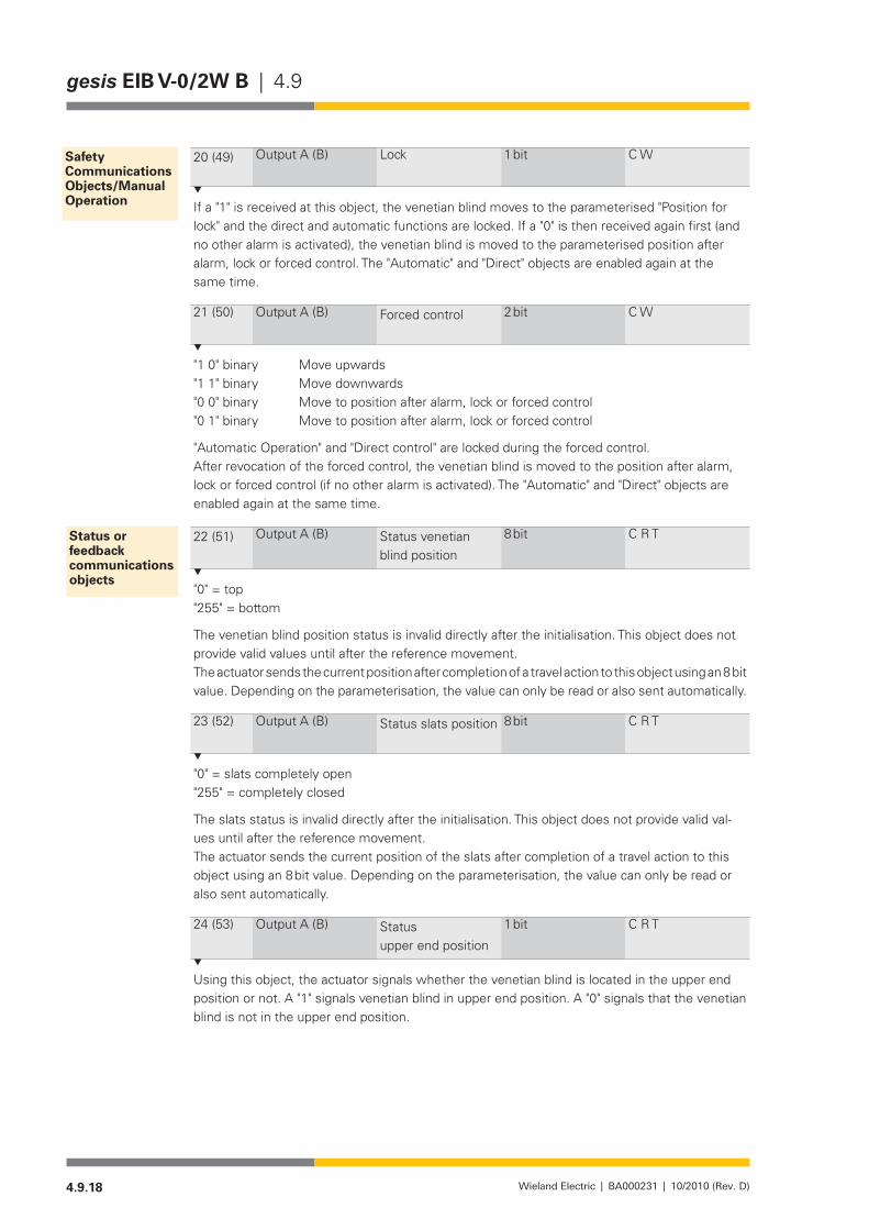
4.9.18 Wieland Electric | BA000231 | 10/2010 (Rev. D)
gesis EIB V-0/2W B | 4.9
20 (49) Output A (B) Lock 1 bit C W
If a "1" is received at this object, the venetian blind moves to the parameterised "Position for lock" and the direct and automatic functions are locked. If a "0" is then received again first (and no other alarm is activated), the venetian blind is moved to the parameterised position after alarm, lock or forced control. The "Automatic" and "Direct" objects are enabled again at the same time.
21 (50) Output A (B) Forced control 2 bit C W
"1 0" binary Move upwards"1 1" binary Move downwards"0 0" binary Move to position after alarm, lock or forced control"0 1" binary Move to position after alarm, lock or forced control
"Automatic Operation" and "Direct control" are locked during the forced control.After revocation of the forced control, the venetian blind is moved to the position after alarm, lock or forced control (if no other alarm is activated). The "Automatic" and "Direct" objects are enabled again at the same time.
22 (51) Output A (B) Status venetian blind position
8 bit C R T
"0" = top"255" = bottom
The venetian blind position status is invalid directly after the initialisation. This object does not provide valid values until after the reference movement.The actuator sends the current position after completion of a travel action to this object using an 8 bit value. Depending on the parameterisation, the value can only be read or also sent automatically.
23 (52) Output A (B) Status slats position 8 bit C R T
"0" = slats completely open"255" = completely closed
The slats status is invalid directly after the initialisation. This object does not provide valid val-ues until after the reference movement.The actuator sends the current position of the slats after completion of a travel action to this object using an 8 bit value. Depending on the parameterisation, the value can only be read or also sent automatically.
24 (53) Output A (B) Status upper end position
1 bit C R T
Using this object, the actuator signals whether the venetian blind is located in the upper end position or not. A "1" signals venetian blind in upper end position. A "0" signals that the venetian blind is not in the upper end position.
Safety Communications Objects/Manual Operation
Status or feedback communications objects

4.9.19Wieland Electric | BA000231 | 10/2010 (Rev. D)
4.9 | gesis EIB V-0/2W B
25 (54) Output A (B) Status lower end position
1 bit C R T
Using this object, the actuator signals whether the venetian blind is located in the lower end position or not. A "1" signals venetian blind in lower end position. A "0" signals that the venetian blind is not in the lower end position.
26 (55) Output A (B) Status object for operation
1 bit C R T
"0": Operation enabled"1": Operation locked
The venetian blind actuator sends the information to this communications object whether the operation via the "Direct" and "Automatic" communications objects is enabled or locked. The op-eration is locked if either any of the "Safety" functions (e.g. weather alarm, lock, forced control) has been activated or if the venetian blind actuator has been switched to manual operation or if the direct and automatic operation are locked simultaneously via communications objects. The operation status is sent after any change.
27(56) Output A (B) Automatic control status
1 bit C R T
The actuator signals that the automatic mode is activated with a "1" to this object.For example, if the output is moved to a safe position due to a wind alarm, the object value is set to "0". The automatic operation cannot influence the output.
28(57) Output A (B) Status byte 8 bit C W
This byte indicates a specific status in each bit. If several bits are set ("1"), the output reacts according to the parameterisation (prioritisation, lock, behaviour in the case of alarm etc.).Key table (all values not listed are not defined!
Bit activated deactivated7 H/C automatic 1 06 Sun automatic 1 05 Wind alarm 1 04 Rain alarm 1 03 Frost alarm 1 02 Forced control 1 01 Disable 1 0
0Manual operation via Test button on the device
1 0
Parameterisation
The parameters in "A/B Safety" and "A/B Manual Operation" refer to the complete venetian blind actuator and its outputs. All other parameters refer to a single output.
The default settings are the settings in the as-delivered state. All settings are reset to the default settings after a reset of the device (program download, ETS).
NOTEDefault settings appear in bold.
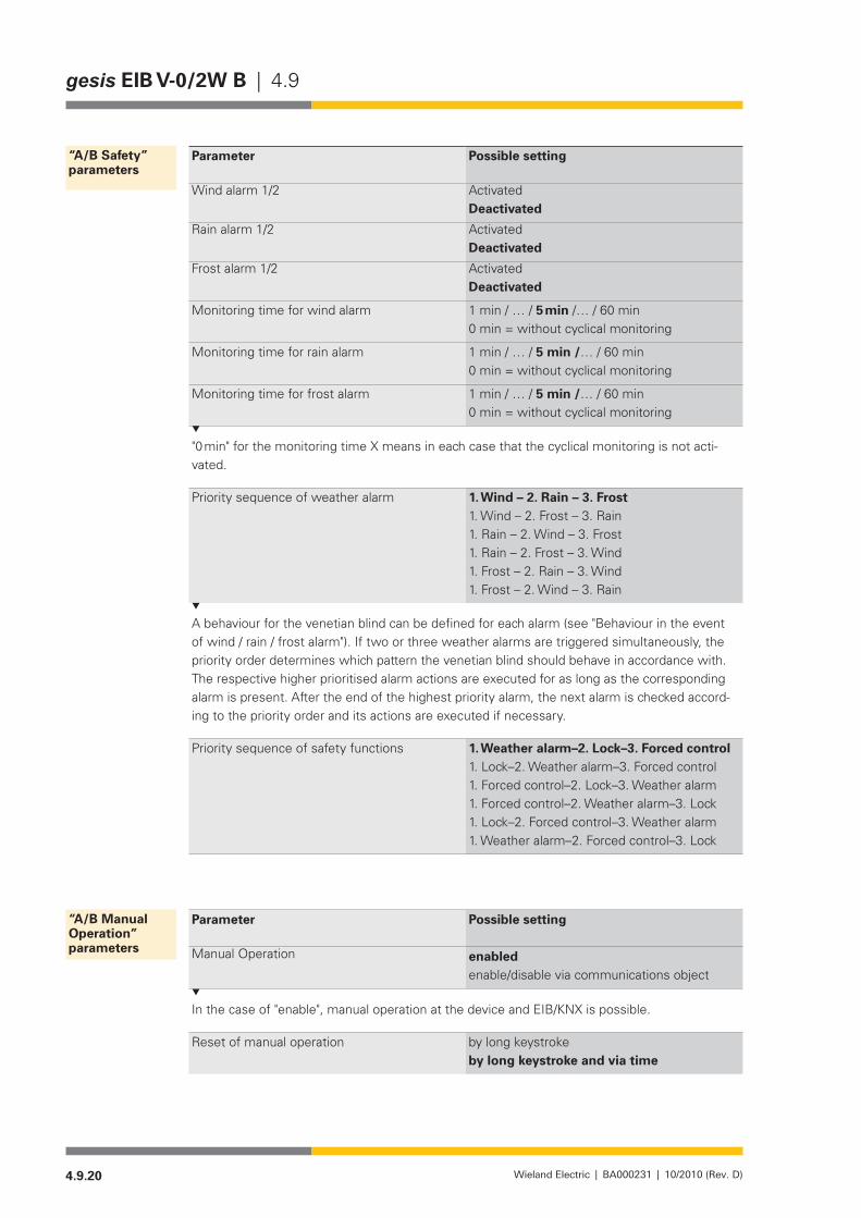
4.9.20 Wieland Electric | BA000231 | 10/2010 (Rev. D)
gesis EIB V-0/2W B | 4.9
Parameter Possible setting
Wind alarm 1/2 ActivatedDeactivated
Rain alarm 1/2 ActivatedDeactivated
Frost alarm 1/2 ActivatedDeactivated
Monitoring time for wind alarm 1min/…/5 min/…/60min0 min = without cyclical monitoring
Monitoring time for rain alarm 1min/…/5 min /…/60min0 min = without cyclical monitoring
Monitoring time for frost alarm 1min/…/5 min /…/60min0 min = without cyclical monitoring
"0 min" for the monitoring time X means in each case that the cyclical monitoring is not acti-vated.
Priority sequence of weather alarm 1. Wind – 2. Rain – 3. Frost1. Wind – 2. Frost – 3. Rain1. Rain – 2. Wind – 3. Frost1. Rain – 2. Frost – 3. Wind1. Frost – 2. Rain – 3. Wind1. Frost – 2. Wind – 3. Rain
A behaviour for the venetian blind can be defined for each alarm (see "Behaviour in the event of wind / rain / frost alarm"). If two or three weather alarms are triggered simultaneously, the priority order determines which pattern the venetian blind should behave in accordance with. The respective higher prioritised alarm actions are executed for as long as the corresponding alarm is present. After the end of the highest priority alarm, the next alarm is checked accord-ing to the priority order and its actions are executed if necessary.
Priority sequence of safety functions 1. Weather alarm–2. lock–3. Forced control1. Lock–2. Weather alarm–3. Forced control1. Forced control–2. Lock–3. Weather alarm1. Forced control–2. Weather alarm–3. Lock1. Lock–2. Forced control–3. Weather alarm1. Weather alarm–2. Forced control–3. Lock
Parameter Possible setting
Manual Operation enabled enable/disable via communications object
In the case of "enable", manual operation at the device and EIB/KNX is possible.
Reset of manual operation by long keystroke by long keystroke and via time
“A/B Safety” parameters
“A/B Manual Operation” parameters

4.9.21Wieland Electric | BA000231 | 10/2010 (Rev. D)
4.9 | gesis EIB V-0/2W B
Reset time (sec) 10/…/60/…/10000s
Time in seconds after the last press of the Test button at the venetian blind actuator. The value "by long keystroke and via time" means that the manual operation is ended either after a long keystroke or after expiry of the specified time whichever occurs first.
Status object for manual operation deactivated send automaticallyread only
Parameter Possible setting
Operating mode venetian blind roller blind continuous operation
Automatic control activated deactivated
The "Automatic Tab" and "Sun" open with the activation.Not present in the "Continuous Operation" operating mode.Different parameter sets are displayed depending on the selected operating mode; these are de-scribed below.
8-bit scene control deactivatedactivated, positions programmable with ETSactivated, positions not programmable with ETS
The "Scene" window is displayed with the activation.Not present in the "Continuous Operation" operating mode.
Behaviour on bus voltage failure no action move upwards move downwards stop
Behaviour on bus voltage recovery move upwards move downwards stopMove to preset position 1 - 4 (not for "Continu-ous Operation")
Notes for bus voltage failure and recovery:Any direction changes for "move upwards" and "move downwards" are executed without •pause on reverse (only for bus voltage failure).In the "Continuous Operation" operating mode, the specified action is not performed until •after expiry of the pause on reverse and the Start-up delay.
“General” parameters (output A, B)
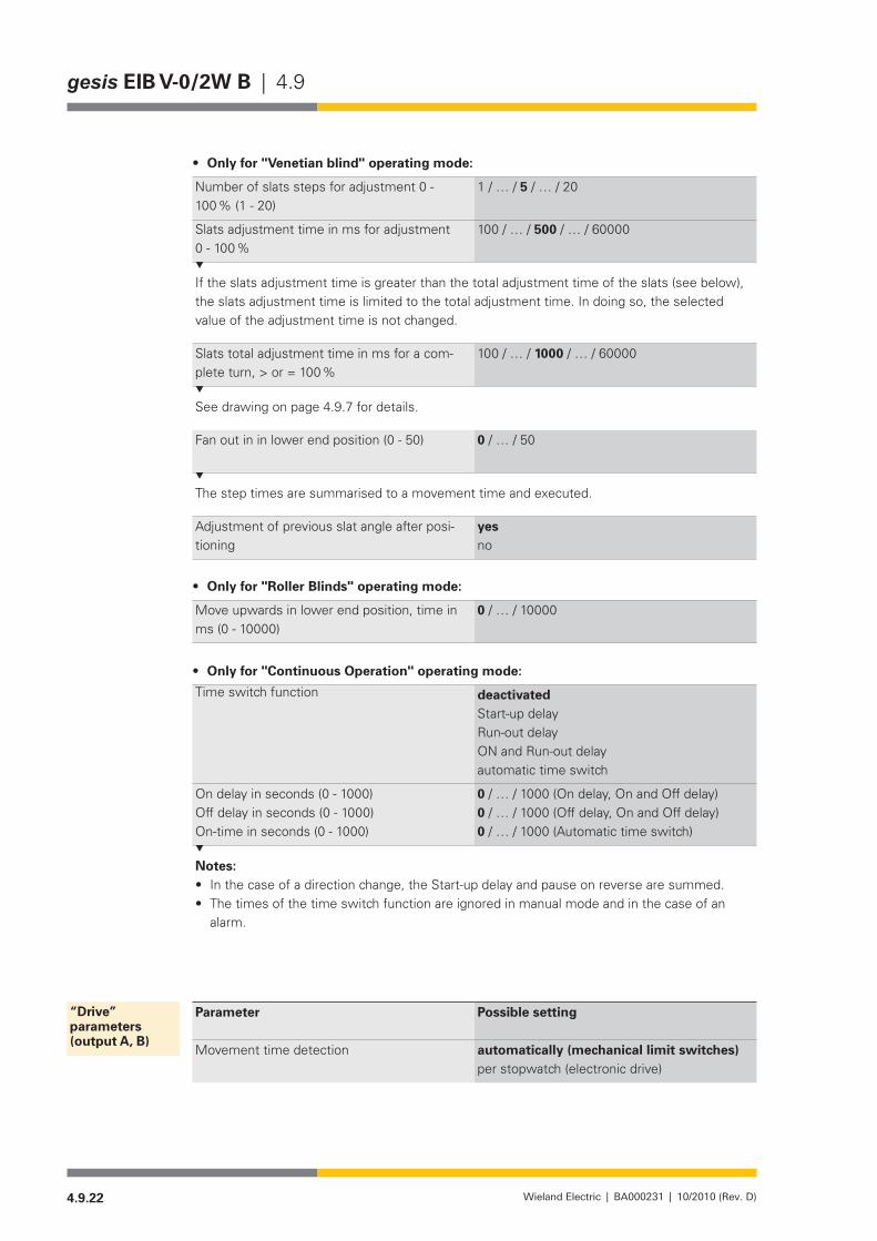
4.9.22 Wieland Electric | BA000231 | 10/2010 (Rev. D)
gesis EIB V-0/2W B | 4.9
Only for "Venetian blind" operating mode: •
Number of slats steps for adjustment 0 - 100 % (1 - 20)
1/…/5/…/20
Slats adjustment time in ms for adjustment 0 - 100 %
100/…/500/…/60000
If the slats adjustment time is greater than the total adjustment time of the slats (see below), the slats adjustment time is limited to the total adjustment time. In doing so, the selected value of the adjustment time is not changed.
Slats total adjustment time in ms for a com-plete turn, > or = 100 %
100/…/1000/…/60000
See drawing on page 4.9.7 for details.
Fan out in in lower end position (0 - 50) 0/…/50
The step times are summarised to a movement time and executed.
Adjustment of previous slat angle after posi-tioning
yesno
Only for "Roller Blinds" operating mode: •
Move upwards in lower end position, time in ms (0 - 10000)
0/…/10000
Only for "Continuous Operation" operating mode: •
Time switch function deactivatedStart-up delayRun-out delayON and Run-out delayautomatic time switch
On delay in seconds (0 - 1000)Off delay in seconds (0 - 1000)On-time in seconds (0 - 1000)
0/…/1000(Ondelay,OnandOffdelay)0/…/1000(Offdelay,OnandOffdelay)0/…/1000(Automatictimeswitch)
Notes:In the case of a direction change, the Start-up delay and pause on reverse are summed.•The times of the time switch function are ignored in manual mode and in the case of an •alarm.
Parameter Possible setting
Movement time detection automatically (mechanical limit switches)per stopwatch (electronic drive)
“Drive” parameters (output A, B)
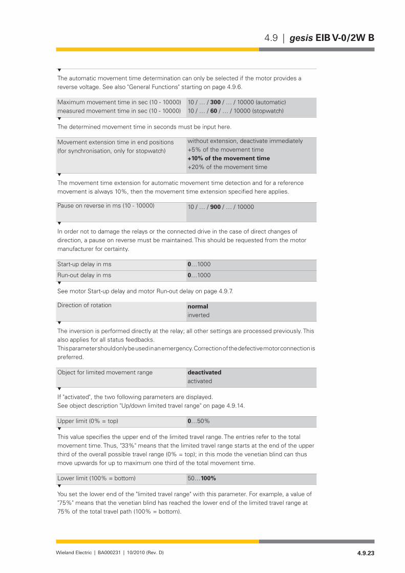
4.9.23Wieland Electric | BA000231 | 10/2010 (Rev. D)
4.9 | gesis EIB V-0/2W B
The automatic movement time determination can only be selected if the motor provides a reverse voltage. See also "General Functions" starting on page 4.9.6.
Maximum movement time in sec (10 - 10000)measured movement time in sec (10 - 10000)
10/…/300/…/10000(automatic)10/…/60/…/10000(stopwatch)
The determined movement time in seconds must be input here.
Movement extension time in end positions (for synchronisation, only for stopwatch)
without extension, deactivate immediately+5% of the movement time +10% of the movement time +20% of the movement time
The movement time extension for automatic movement time detection and for a reference movement is always 10%, then the movement time extension specified here applies.
Pause on reverse in ms (10 - 10000) 10/…/900/…/10000
In order not to damage the relays or the connected drive in the case of direct changes of direction, a pause on reverse must be maintained. This should be requested from the motor manufacturer for certainty.
Start-up delay in ms 0…1000
Run-out delay in ms 0…1000
See motor Start-up delay and motor Run-out delay on page 4.9.7.
Direction of rotation normalinverted
The inversion is performed directly at the relay; all other settings are processed previously. This also applies for all status feedbacks.This parameter should only be used in an emergency. Correction of the defective motor connection is preferred.
Object for limited movement range deactivated activated
If "activated", the two following parameters are displayed.See object description "Up/down limited travel range" on page 4.9.14.
Upper limit (0% = top) 0…50%
This value specifies the upper end of the limited travel range. The entries refer to the total movement time. Thus, "33%" means that the limited travel range starts at the end of the upper third of the overall possible travel range (0% = top); in this mode the venetian blind can thus move upwards for up to maximum one third of the total movement time.
Lower limit (100% = bottom) 50…100%
You set the lower end of the "limited travel range" with this parameter. For example, a value of "75%"meansthatthevenetianblindhasreachedthelowerendofthelimitedtravelrangeat75%ofthetotaltravelpath(100%=bottom).
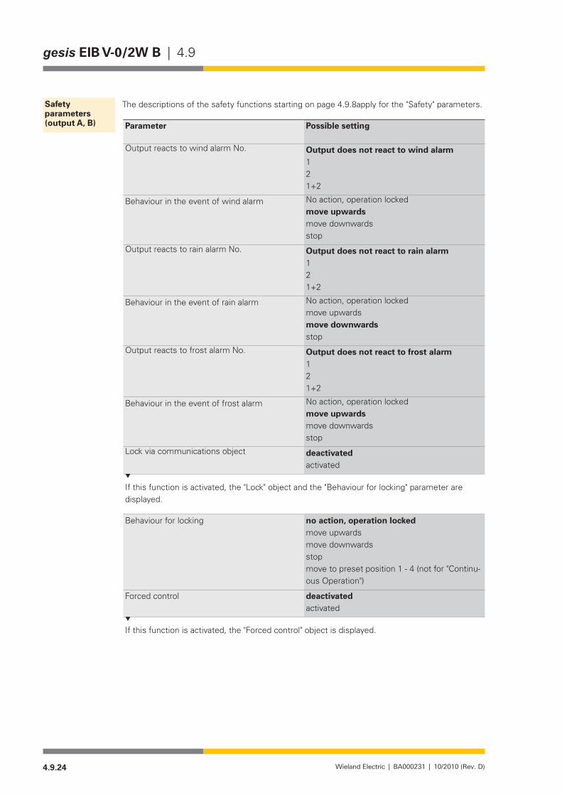
4.9.24 Wieland Electric | BA000231 | 10/2010 (Rev. D)
gesis EIB V-0/2W B | 4.9
The descriptions of the safety functions starting on page 4.9.8apply for the "Safety" parameters.
Parameter Possible setting
Output reacts to wind alarm No. Output does not react to wind alarm121+2
Behaviour in the event of wind alarm No action, operation lockedmove upwards move downwards stop
Output reacts to rain alarm No. Output does not react to rain alarm121+2
Behaviour in the event of rain alarm No action, operation lockedmove upwards move downwards stop
Output reacts to frost alarm No. Output does not react to frost alarm121+2
Behaviour in the event of frost alarm No action, operation lockedmove upwards move downwards stop
Lock via communications object deactivatedactivated
If this function is activated, the "Lock" object and the "Behaviour for locking" parameter are displayed.
Behaviour for locking no action, operation locked move upwards move downwards stop move to preset position 1 - 4 (not for "Continu-ous Operation")
Forced control deactivatedactivated
If this function is activated, the "Forced control" object is displayed.
Safety parameters (output A, B)
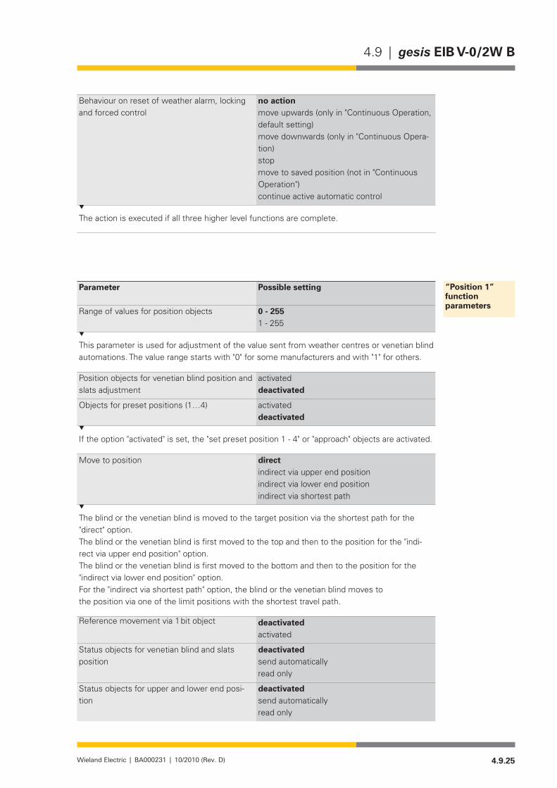
4.9.25Wieland Electric | BA000231 | 10/2010 (Rev. D)
4.9 | gesis EIB V-0/2W B
Behaviour on reset of weather alarm, locking and forced control
no actionmove upwards (only in "Continuous Operation, default setting)move downwards (only in "Continuous Opera-tion)stopmove to saved position (not in "Continuous Operation")continue active automatic control
The action is executed if all three higher level functions are complete.
Parameter Possible setting
Range of values for position objects 0 - 255 1 - 255
This parameter is used for adjustment of the value sent from weather centres or venetian blind automations. The value range starts with "0" for some manufacturers and with "1" for others.
Position objects for venetian blind position and slats adjustment
activated deactivated
Objectsforpresetpositions(1…4) activated deactivated
If the option "activated" is set, the "set preset position 1 - 4" or "approach" objects are activated.
Move to position direct indirect via upper end position indirect via lower end position indirect via shortest path
The blind or the venetian blind is moved to the target position via the shortest path for the "direct" option.The blind or the venetian blind is first moved to the top and then to the position for the "indi-rect via upper end position" option.The blind or the venetian blind is first moved to the bottom and then to the position for the "indirect via lower end position" option.For the "indirect via shortest path" option, the blind or the venetian blind moves tothe position via one of the limit positions with the shortest travel path.
Reference movement via 1 bit object deactivated activated
Status objects for venetian blind and slats position
deactivated send automaticallyread only
Status objects for upper and lower end posi-tion
deactivated send automaticallyread only
“Position 1” functionparameters
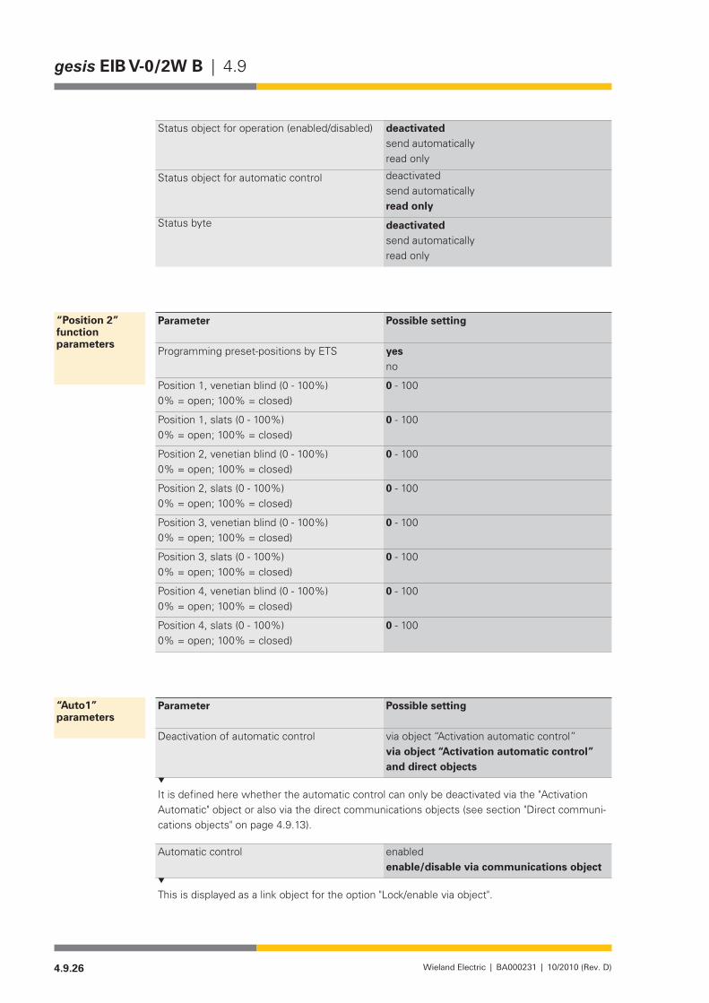
4.9.26 Wieland Electric | BA000231 | 10/2010 (Rev. D)
gesis EIB V-0/2W B | 4.9
Status object for operation (enabled/disabled) deactivated send automaticallyread only
Status object for automatic control deactivated send automaticallyread only
Status byte deactivated send automaticallyread only
Parameter Possible setting
Programming preset-positions by ETS yesno
Position 1, venetian blind (0 - 100%) 0% = open; 100% = closed)
0 - 100
Position 1, slats (0 - 100%) 0% = open; 100% = closed)
0 - 100
Position 2, venetian blind (0 - 100%) 0% = open; 100% = closed)
0 - 100
Position 2, slats (0 - 100%) 0% = open; 100% = closed)
0 - 100
Position 3, venetian blind (0 - 100%) 0% = open; 100% = closed)
0 - 100
Position 3, slats (0 - 100%) 0% = open; 100% = closed)
0 - 100
Position 4, venetian blind (0 - 100%) 0% = open; 100% = closed)
0 - 100
Position 4, slats (0 - 100%) 0% = open; 100% = closed)
0 - 100
Parameter Possible setting
Deactivation of automatic control via object “Activation automatic control”via object “Activation automatic control” and direct objects
It is defined here whether the automatic control can only be deactivated via the "Activation Automatic" object or also via the direct communications objects (see section "Direct communi-cations objects" on page 4.9.13).
Automatic control enabled enable/disable via communications object
This is displayed as a link object for the option "Lock/enable via object".
“Position 2” function parameters
“Auto1” parameters
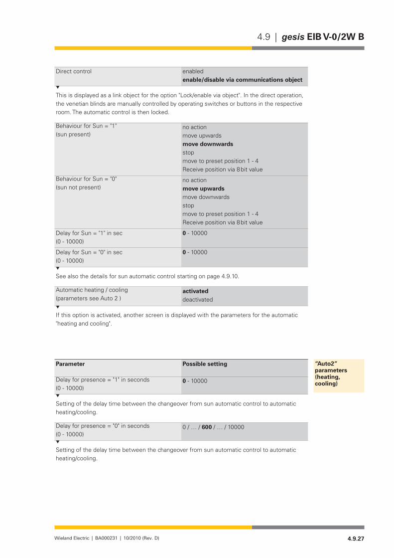
4.9.27Wieland Electric | BA000231 | 10/2010 (Rev. D)
4.9 | gesis EIB V-0/2W B
Direct control enabled enable/disable via communications object
This is displayed as a link object for the option "Lock/enable via object". In the direct operation, the venetian blinds are manually controlled by operating switches or buttons in the respective room. The automatic control is then locked.
Behaviour for Sun = "1" (sun present)
no action move upwards move downwards stop move to preset position 1 - 4Receive position via 8 bit value
Behaviour for Sun = "0"(sun not present)
no action move upwards move downwards stop move to preset position 1 - 4Receive position via 8 bit value
Delay for Sun = "1" in sec(0 - 10000)
0 - 10000
Delay for Sun = "0" in sec(0 - 10000)
0 - 10000
See also the details for sun automatic control starting on page 4.9.10.
Automatic heating / cooling(parameters see Auto 2 )
activated deactivated
If this option is activated, another screen is displayed with the parameters for the automatic "heating and cooling".
Parameter Possible setting
Delay for presence = "1" in seconds(0 - 10000)
0 - 10000
Setting of the delay time between the changeover from sun automatic control to automatic heating/cooling.
Delay for presence = "0" in seconds(0 - 10000)
0/…/600/…/10000
Setting of the delay time between the changeover from sun automatic control to automatic heating/cooling.
“Auto2” parameters (heating, cooling)
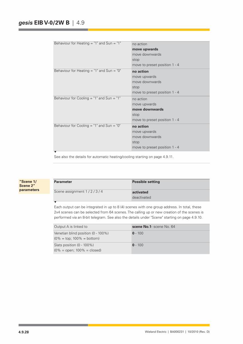
4.9.28 Wieland Electric | BA000231 | 10/2010 (Rev. D)
gesis EIB V-0/2W B | 4.9
Behaviour for Heating = "1" and Sun = "1" no action move upwards move downwards stop move to preset position 1 - 4
Behaviour for Heating = "1" and Sun = "0" no action move upwards move downwards stop move to preset position 1 - 4
Behaviour for Cooling = "1" and Sun = "1" no action move upwards move downwards stop move to preset position 1 - 4
Behaviour for Cooling = "1" and Sun = "0" no action move upwards move downwards stop move to preset position 1 - 4
See also the details for automatic heating/cooling starting on page 4.9.11.
Parameter Possible setting
Scene assignment 1 / 2 / 3 / 4 activateddeactivated
Each output can be integrated in up to 8 (4) scenes with one group address. In total, these 2x4 scenes can be selected from 64 scenes. The calling up or new creation of the scenes is performed via an 8-bit telegram. See also the details under "Scene" starting on page 4.9.10.
Output A is linked to scene No.1- scene No. 64
Venetian blind position (0 - 100%)(0% = top; 100% = bottom)
0 - 100
Slats position (0 - 100%)(0% = open; 100% = closed)
0 - 100
“Scene 1/ Scene 2“ parameters
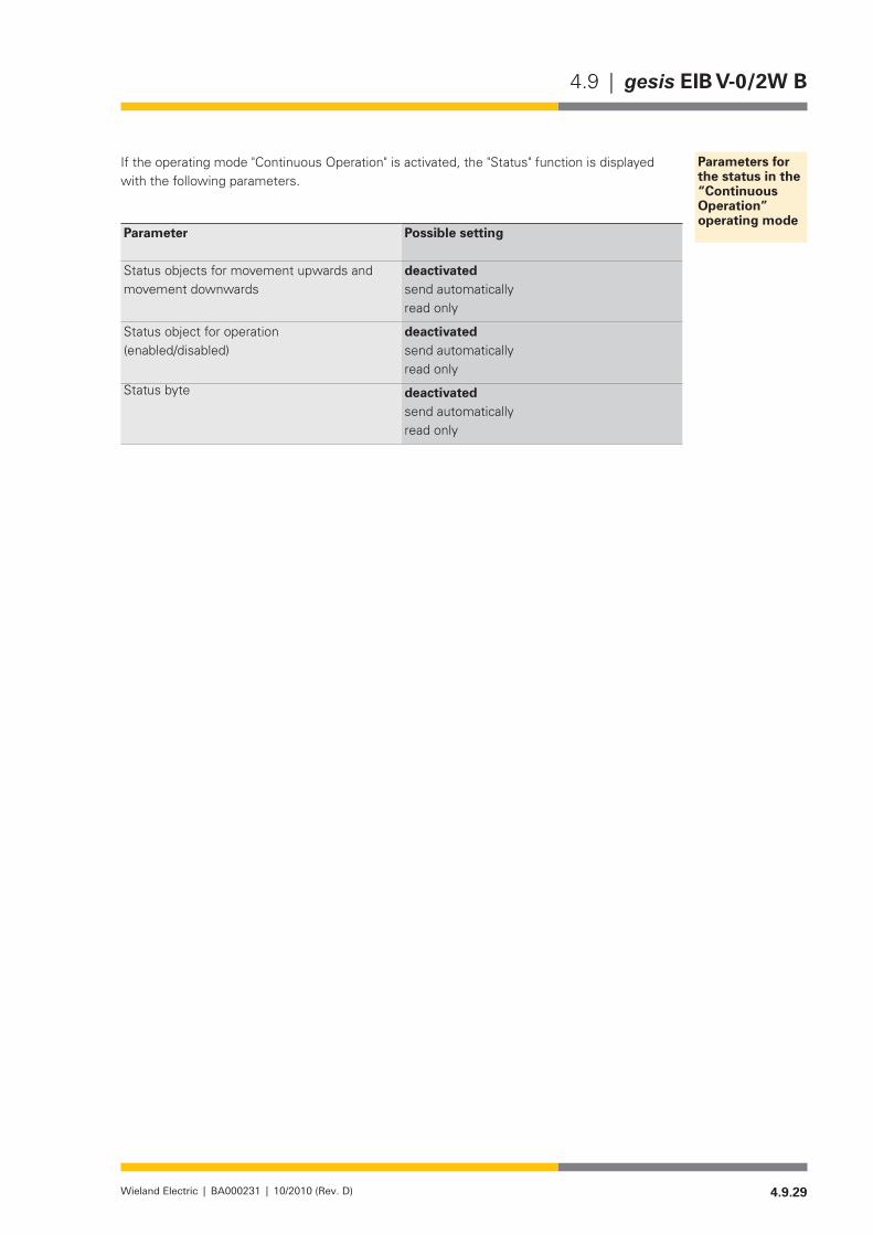
4.9.29Wieland Electric | BA000231 | 10/2010 (Rev. D)
4.9 | gesis EIB V-0/2W B
If the operating mode "Continuous Operation" is activated, the "Status" function is displayed with the following parameters.
Parameter Possible setting
Status objects for movement upwards and movement downwards
deactivated send automaticallyread only
Status object for operation(enabled/disabled)
deactivated send automaticallyread only
Status byte deactivated send automaticallyread only
Parameters for the status in the “Continuous Operation” operating mode

4.9.30 Wieland Electric | BA000231 | 10/2010 (Rev. D)
gesis EIB V-0/2W B | 4.9

4.10.1Wieland Electric | BA000231 | 10/2010 (Rev. D)
4.10 | gesis EIB V-0/2W B SP
gesis EIB V-0/2W B SP
General Description
Designation• Venetian blind actuator, 2-fold switch outputType• gesis EIB V-0/2W B SPOrder number• 83.020.0221.4Device type• EIB venetian blind actuator 2-fold switch output
non-floating outputs 230 V AC Design• Device with plug-in connections for surface mounting in closed
rooms, attachment with two screws Mains power connection • 1-phase/3-pin mains power feed-inProgram name• (ETS application program)
gesis EIB V-0/2W B 1.0
Functional Description
The venetian blind actuator receives telegrams from the EIB/KNX bus and switches two inde-pendent drives with two movement directions (e.g. venetian blind motors) via two mutually interlocked relays Both outputs are non-floating. This means that each output is already linked internally with the potentials N, PE and linked with an outer conductor of the mains voltage via the corresponding relay contacts.
Any venetian blind and slat positions can be approached via 8-bit control commands. In doing so, the control here is time-dependent. As the actuator does not receive any unique posi-tion feedback from the controlled drive, the accuracy largely depends on the used motor, the gearbox and the mechanical quality of the venetian blind.
Drives with electromechanical limit switches or with integrated electronics for disconnection at the limit positions can be connected to the outputs. For drives with electromechanical limit switches which provide reverse voltage from the motor, automatic adjustment of the move-ment time and synchronisation in the limit positions are performed. It must be ensured that the reverse voltage is within the limits specified in this data sheet. For drives with integrated electronics and for drives which do not provide any reverse voltage, the movement time must be measured as accurately as possible and adjusted in the application program.
NOTE:The parallel operation of drives with electromechanical limit switches on one output and mixed operation of the drive types mentioned above on one output are not permitted.
However, several decoupled drives using cut-off relays can be controlled as a group. The param-eterisation is then performed as for a drive without reverse voltage. Movement times and start positions of the individual drives must be identical for this application.
Time-independent control (only Up/Down/Stop) of a motor is also possible with the actuator.Application software is required for the parameterisation and operation of the device. This software
is loaded into the device using the Engineering Tool Software (ETS).
GeneralDescription
Drives withelectromechanicallimit switches
Drives with integrated electronics and decoupled drivesusing cut-off relays

4.10.2 Wieland Electric | BA000231 | 10/2010 (Rev. D)
gesis EIB V-0/2W B SP | 4.10
Operation and display elements
• "Program" button The programming mode for the download of the physical address can be activated or deactivated by pressing this button.
• "Test" button For manual operation of the outputs. The statuses Up / Stop / Down / Stop etc. are adopted alternately by pressing this button. Pressing for longer than 0.5 s ends the manual mode. Depending on the parameter settings, the manual mode can also be ended automatically after a defin-able time. Except for the alarm functions, operation via the bus is not possible during the manual mode.
• lED "Program" (red) Indication of the programming status for the physical address, the operating status and error display.
• Off Thedeviceisinthenormaloperatingconditionwhenbusvoltageis present. If the LED does not light after pressing the "Program" button, there is no bus voltage.
• On IftheLEDlightscontinuously,thedeviceisintheprogrammingmode for the physical address.
• Flashing IftheredLEDflashes,eitheranincorrectordefectiveapplicationprogram could have been loaded (fast flashing) or the device is in the manual operation operating mode (slow flashing).
Technical Data
Bus connectionConnection to BST 14i2 socket, 2-pin, colour green, coding EIB, (1+ / 2-)Bus voltage 24 V DC (EIB/KNX Standard Twisted pair TP1)Current consumption approx. 6 mAPower consumption typically 150 mWMains power connectionConnection to GST 18i3 socket, 3-pin, colour black,
(L / PE / N)Rated voltage 230 V AC (-15% / +10%)Rated frequency 50-60 HzRated current 16 APower consumption dependent on the connected consumersRecommended fuse protection 3-pin circuit breaker B16AOutputsNumber 2 outputs with reverse voltage detection for the connec-
tion of venetian blind motorsConnection to GST 18i4 male connector, 4-pin, black,
[2 (down) / N / PE / 1 (up)]Rated voltage 230 V AC (from the mains power connection)Rated current 8 A (ohmic load)Short circuit protection no short circuit protectionMinimum load 2,5 VASwitching capacity / service life 2000 VA cos ϕ=1: 105 switching cycles
700VAcosϕ=0.7(inductiveload):3x10⁵ switching cyclesPermissible reverse voltage of the connected motors
max. 300 V AC, min. 140 V AC for automatic detection of venetian blind operating time
Cable length at the output for evaluation of the reverse voltage: max. 50 mElectrical safetyProtection class IProtection class IP20 (according to EN 60529)Degree of soiling 2
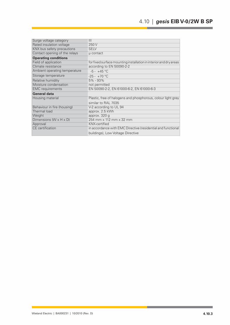
4.10.3Wieland Electric | BA000231 | 10/2010 (Rev. D)
4.10 | gesis EIB V-0/2W B SP
Surge voltage category IIIRated insulation voltage 250 VKNX bus safety precautions SELVContact opening of the relays µ contactOperating conditionsField of application for fixed surface mounting installation in interior and dry areasClimate resistance according to EN 50090-2-2Ambient operating temperature -5-+45°CStorage temperature -25-+70°CRelative humidity 5% - 93%Moisture condensation not permittedEMC requirements EN 50090-2-2, EN 61000-6-2, EN 61000-6-3General dataHousing material Plastic, free of halogens and phosphorous, colour light grey
similartoRAL7035Behaviour in fire (housing) V-2 according to UL 94Thermal load approx. 2.5 kWhWeight approx. 320 gDimensions (W x H x D) 254 mm x 112 mm x 32 mmApproval KNX-certifiedCE certification in accordance with EMC Directive (residential and functional
buildings), Low Voltage Directive

4.10.4 Wieland Electric | BA000231 | 10/2010 (Rev. D)
gesis EIB V-0/2W B SP | 4.10
Installation and dimensions
Mounting type Attachment with 2 screws•Recommended screws 4.5 x 40 mm, for use with 6 mm plugs•Drilled holes spacing X=230.3 / Y=64.5 mm•
XYInfeed
Outputs
1–"Program" LED (red)2–"Program" button3–"Test" button4–Mains power connection5–EIB bus connection6,7–VenetianblindoutputsA1/A2
4.10.5Wieland Electric | BA000231 | 10/2010 (Rev. D)
4.10 | gesis EIB V-0/2W B SP
Accessories
Accessories for 83.020.0221.4 (gesis EIB V-0/2W B SP)
NOTE:Whenusingthe7-poleflatcable,themainsandEIBadaptersmustbespacedapart.A spacer is included in the scope of supply of the EIB Adapter 93.421.1153.0. It is not possible to use the EST2i3 product program.
Incoming supply when using the flat cable system (7-pole)7-poleflatcable• 00.702.0323.9EIB Adapter• 93.421.1153.0Mains adapter, with measuring tap external •conductor L1
92.031.4153.1
Mains adapter, with measuring tap external •conductor L2
92.031.4253.1
Mains adapter, with measuring tap external •conductor L3
92.031.4353.1
Mains adapter/device interlock• 05.587.3156.1
Separate incoming supply for mains (GST 18i5) and EIB (BST 14i2)Mains, female connector, screw connection• 92.931.3053.1Mains, female connector, spring-loaded connec-•tion
92.933.0053.1
Mains starter lead, female – free end• 92.238.x003.1 (x = length in metres)Mains, extender lead, female – male• 92.238.x000.1 (x = length in metres)EIB, female connector, spring-loaded connection• 93.421.0553.1EIB, starter lead, female – free end• 94.425.x003.7(x=lengthinmetres)EIB, extender lead, female – male• 94.425.x000.7(x=lengthinmetres)
EIB branch (BST 14i2) when using the combination distribution blockEIB, male connector, spring-loaded connection• 93.422.0553.1EIB, starter lead, male – free end• 94.425.x004.7(x=lengthinmetres)EIB, extender lead, female – male• 94.425.x000.7(x=lengthinmetres)
Venetian blind outputs (GST 18i4)Male connector, screw connection• 92.944.3053.1Male connector, spring-loaded connection• 93.944.1053.1Starter lead, male – free end• 92.207.x004.1(x=lengthinmetres)Extender lead, male - female• 92.207.x000.1(x=lengthinmetres)
Product database for import in ETS from version V1.1www.wieland-electric.com• Language selection: English Search term "Product database"

4.10.6 Wieland Electric | BA000231 | 10/2010 (Rev. D)
gesis EIB V-0/2W B SP | 4.10
Description of the device functions
Venetian blind operating mode
This operating mode is used for actuating sun and anti-glare protection using adjustable angle slats (e.g. for light deflection). In this operating mode, the venetian blinds can also be ascended and descended, the stop function executed and the slats of the venetian blinds moved.
Roller blind operating mode
This operating mode is used for the actuation of roller blinds, awnings, window and wall cover-ings, gates, doors and windows. Apart from the slat function, the roller blind functionality is identical to that of the Venetian blind.
Continuous Operation operating mode
Differently from the other two operating modes, no automatic deactivation after a parameter-ised time is performed in this operating mode. Ventilation flaps can be opened and closed in accordance with the requirements in the Heating and Cooling area. This operating mode can also be used for stairway light, actuators or other switching purposes.
The functions can be set separately for each output.
Movement times
Total movement time –
The total movement time is the time needed to move a venetian blind from the "closed" position to the "maximum open" position. A venetian blind is moved in one direction until it
receives a Stop command or until it has reached one of the two end positions (top, bottom) and the motor is deacti-vated via limit switches.
If an end position is detected, the output concerned is also disconnected from the power supply.
If the venetian blind does not have any limit switches, the venetian blind moves in a direction until the actuator receives a Stop command or the total movement time including a parameter-isable run-on time has elapsed.
! In this case, an output is not disconnected from the power supply until after expiry of the total runtime + run-on time!It is also possible to input a value
smaller than 100% for the "Limit position 100%" value. The run-on time is not taken into account here and the limit position is reached according to the parameterised value.
Operating Modes
General Functions
0%
100%
upper endswitch
lower endswitch
Movem
ent up/down
Total movem
ent time
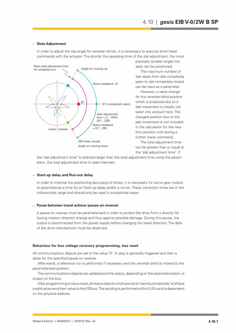
4.10.7Wieland Electric | BA000231 | 10/2010 (Rev. D)
4.10 | gesis EIB V-0/2W B SP
– Slats Adjustment
In order to adjust the slat angle for venetian blinds, it is necessary to execute short travel commands with the actuator. The shorter the operating time of the slat adjustment, the more
precisely (smaller angle) the slats can be positioned.
The maximum number of slat steps from slat completely open to slat completely closed can be input as a parameter.
However, a value change for the venetian blind position which is produced due to a slat movement is initially not taken into account here. The changed position due to the slat movement is not included in the calculation for the new limit position until during a further travel command.
The total adjustment time can be greater than or equal to the "slat adjustment time". If
the "slat adjustment time" is selected larger than the total adjustment time using the param-eters, the total adjustment time is used internally.
– Start-up delay and Run-out delay
In order to improve the positioning (accuracy) of drives, it is necessary for some gear motors to parameterise a time for an Start-up delay and/or a run-on. These correction times are in the milliseconds range and should only be used in exceptional cases.
Pause between travel actions (pause on reverse) –
A pause on reverse must be parameterised in order to protect the drive from a directly fol-lowing rotation direction change and thus against possible damage. During this pause, the output is disconnected from the power supply before changing the travel direction. The data of the drive manufacturer must be observed.
Behaviour for bus voltage recovery programming, bus reset
All communications objects are set to the value "0". A stop is generally triggered and then a delay for the specified pause on reverse.
Afterwards, a reference run is performed if necessary and the venetian blind is moved to the parameterised position.
The communications objects are updated and the status, depending on the parameterisation, is output on the bus.
After programming or a bus reset, all status objects which are set to "send automatically" and have a valid value send their value to the EIB bus. The sending is performed within 5-20 s and is dependent on the physical address.
Slats total adjustment timefor complete turn Angle on moving up
Status feedback =0
slats adjustmenttime = 0…100%(0/1…255)
Status feedback= 0/1…255
Angle on moving down
255 (fully closed)
0/1 (completely open)
inside outside

4.10.8 Wieland Electric | BA000231 | 10/2010 (Rev. D)
gesis EIB V-0/2W B SP | 4.10
Bus voltage failure and recovery
The behaviour in the case of bus voltage failure can be parameterised. The reverse on pause is not taken into account for a direction change of the movement.
Safety Functions
All safety functions have priority over all other functions. In the case of several activated safety functions, the priorities of the individual functions can be parameterised via the ETS and thus defined with each other.
lock (1 bit command; "0" = no lock, "1" = lock) –
In the case of a lock, the respective venetian blind is moved to the parameterised position and the operation is locked. When the lock is removed, the output is enabled depending on the other safety functions.
The following commands are executed:
Bit 0 Bit 1 Comment0 0 Operation enabled0 1 Operation enabled1 0 Moving up and locking1 1 Moving down and locking
Venetian blind cleaning, window cleaning / fire alarm (2 bit command) forced control –
When the forced control is deactivated, the output is enabled depending on the other safety functions.
Weather Alarms
All weather alarms (2x wind, 2x rain, 2x frost) function according to the same principle. It can be selected for each output which of the alarms it should react to. Multiple assignments are also possible. The cyclical monitoring of the alarms can be varied according to time or deactivated using parameters. The behaviour of the output in the event of an alarm is defined according to the assignment of the weather alarms to the outputs.
The priority sequence of the three weather alarms (wind, rain, frost) can be parameterised.In the case of revocation of all alarms, the respective output is moved to the parameterised
position (parameter: "Behaviour on reset of weather alarm, locking and forced control").The following applies for all weather alarms: 0 = no alarm, 1 = alarm.
Manual Operation Mode
For manual operation of the outputs. The statuses Up / Stop / Down / Stop etc. are adopted alternately by pressing this button. Pressing for longer than 0.5 s ends the manual mode. Depending on the parameter settings, the manual mode can also be ended automatically after a definable time. Except for the alarm functions, operation via the bus is not possible during the manual mode.
In the manual mode, the venetian blinds of both outputs are always operated symmetrically (unless one output is locked or there is an activated alarm at an output).

4.10.9Wieland Electric | BA000231 | 10/2010 (Rev. D)
4.10 | gesis EIB V-0/2W B SP
Function of the single button operation:
<0.5 s >0.5 s
pressed
on
up
up
down
down
stopped
stopped
Keystroke
LED
Manual op.
Venetianblindoutput 1
Venetianblindoutput 2
onoff
off
1x short keystroke (<0.5 s): Manual operation ON •(LED flashes at 0.5 s intervals)1x short keystroke: venetian blind moves downwards.•1x short keystroke: venetian blind stops.•1x short keystroke: venetian blind moves downwards.•1x short keystroke: venetian blind stops.•1x long keystroke (<0.5 s): Manual mode is ended, venetian blind stops.•
You can define whether the manual mode is only ended by a long keystroke (>0.5 s) or also by expiry of a time parameterised by yourself. If no button is pressed during this time, the actuator returns to bus operation.
Determination of the position
In order to determine a position exactly, a reference run is initially necessary. The reference run determines and saves the maximum runtime between the two limit switches. The reference run is performed with the first positioning command.
Thus, the current position and the slat position for the venetian blinds can be determined after each travel command. The position values are compared again after any of the two limit switches is reached. If a position is approached and a slat movement is performed afterwards, the position of the venetian blind is changed due to the slat movement. This changed position value is taken into account internally for a new positioning. Constant readjustment of the posi-tion in the case of automatic sun protection or multiple sending of the same position is there-fore ruled out.
It can also be selected using the "Move to position" parameter whether the position should be approached directly or whether the position should be controlled via one of the limit switches. This can be important for the approaching of scenes.
Position movement 0…100 %
The venetian blind is moved to the required position using an 8 bit command. The slat can be positioned in any angle for the venetian blind using another 8 bit command.
For example, the position for venetian blind and slat can be set here using a button or a visualisation.
Positioning

4.10.10 Wieland Electric | BA000231 | 10/2010 (Rev. D)
gesis EIB V-0/2W B SP | 4.10
Venetian blind (slat) preset position
Up to four preset positions for each output can be parameterised with the ETS and called up with a 1 bit command.
Currently set positions can be defined as new preset positions and saved using a 1-bit command. The previously defined positions are then overwritten.
Scene
Up to 64 scenes can be managed via an 8 bit telegram using a single group address.The scene numbers and the information whether the scene should be saved or called up are
included in this 8 bit telegram.Like a preset position, this 8-bit scene control can also be called up or newly defined posi-
tions saved as a scene using a button or another operating element (for example, a visualisa-tion).Up to four scenes can be assigned per output. This means: one module with two venetian blind outputs can be linked to up to eight scenes.
Structure of 8 bit telegram for scenes:
Bit 7 6 5 4 3 2 1 0 Scenecall up 0 X 0 0 0 0 0 0 1
0 X 0 0 0 0 0 1 20 X 0 0 0 0 1 0 30 X 0 0 0 0 1 1 40 X 0 0 0 1 0 0 5
etc.
save 1 X 0 0 0 0 0 0 11 X 0 0 0 0 1 0 21 X 0 0 0 0 1 0 31 X 0 0 0 0 1 1 41 X 0 0 0 1 0 0 5
Sun automatic control
The automatic sun protection automatically positions the venetian blind according to the sun-light. The venetian blind actuator receives the information whether the sun is shining directly on the corresponding window or corresponding façade via a brightness sensor connected to the "Sun" (1-bit) object. In the case of exceeding or falling below a threshold value on the brightness sensor, the venetian blind actuator, after expiry of a defined delay time, adjusts the venetian blind to one of two previously parameterised positions (position for "Sun" = 1, direct sunlight; or position for "Sun" = 0, no direct sunlight).
The incidence of light can also be changed for a venetian blind using the slats. This is done using the function "Slat position".
The automatic mode can be deactivated and activated using a 1-bit object. A direct travel com-mand (e.g. move to position, 8 bit) of the user deactivates the automatic mode.
The automatic mode can also be locked (and enabled) using a communications object.
Automatic Functions

4.10.11Wieland Electric | BA000231 | 10/2010 (Rev. D)
4.10 | gesis EIB V-0/2W B SP
Automatic heating / cooling
The "Heating/Cooling" function controls the venetian blind according to the required heat in the room.
If the room should be heated and the sun is shining, the venetian blind is raised. In order to •reduce heat loss in the absence of sunlight (e.g. at night), inside curtains can also be closed.If the room should be cooled, the venetian blind is lowered if the sun is shining and raised •if the sun is not directly shining into the room. Inside curtains can be closed independently of the sunlight, particularly in air-conditioned rooms, in order to reduce the load of the air conditioner.
Accordingly, four positions can be parameterised:
Sun = 0 Position 1Heating = 1 Sun = 1 Position 2
Sun = 0 Position 3Cooling = 1 Sun = 1 Position 4
A presence detector can. for example, toggle between automatic sun protection (persons in the room) and automatic heating/cooling (nobody in the room). Whether heating or cooling should be performed can also be controlled by a temperature sensor or external thermostat.
Deactivation/activation of the automatic control
The user would frequently like to decide for himself whether he would like the automatic opera-tion or, for example, move the venetian blinds himself. This can be done using a push button sensor or a direct travel command. The automatic mode is deactivated with this. In the reverse case, it must be possible to activate the automatic mode again. The activated function can be displayed accordingly.
Status messages
The following status messages are available:
Status of the venetian blind position as 8 bit value•Status of the slat as 8 bit value•Status of the upper end position (1 bit)•Status of the lower end position (1 bit)•Operation enabled/locked status (1 bit)•Status object for automatic control (1 bit)•Manual operation status (1 bit)•Status byte (automatic sun protection, automatic heating/cooling, wind alarm, rain alarm, •frost alarm, forced control, lock). Only one of the functions in brackets can be activated in the status byte.
The status messages can be parameterised and called up individually for each output. Further details can be found in the respective object description.

4.10.12 Wieland Electric | BA000231 | 10/2010 (Rev. D)
gesis EIB V-0/2W B SP | 4.10
Application Program
Program name• gesis EIB V-0/2W BProgram version• 1.0Product allocation• gesis EIB V-0/2W B 83.020.0221.0
gesis EIB V-0/2W B SP 83.020.0221.4Source of supply• www.gesis.com
Info Service/Download/gesis Product databaseProduct Description• EIB venetian blind actuator 2-fold switch output (230 V AC)
Non-floating outputs,all plug-in connections, surface mounting
Manufacturer•Product series•Product type•
Wieland Electric GmbH gesis EIB V Venetian blind
The application program enables simple and complex venetian blind controls, roller blind con-trols and also makes it possible to activate the outputs in continuous operation. Both the com-munications objects as well as the parameters are dynamically displayed and hidden depending on the parameter selection. A simple venetian blind control with four objects is available in the default settings. This can be extended using the parameter settings to a complex venetian blind system with up to 65 communications objects (operating mode "Venetian blind").
Possible Operating Modes maximum number of communications objects
Venetian blind 65
Roller blind 60Continuous operation 23
These communications objects can be subdivided into groups:Alarms and manual operation •Seven objects which can be created in every operating mode and can be used jointly by the outputs A/B
Direct Communications Objects •Eleven objects per output. These are objects which should not be used by the venetian blind actuation. For example, this includes a travel command from a button. The automation can be deactivated using these objects depending on the parameter settings.
Automatic Communications Objects •Nine objects per output. These are objects which are used by sensors or by central automa-tion equipment. The objective of these controls is frequently energy saving depending on time, weather, climate values and the presence of persons.
Safety Communications Objects •Six common objects for outputs A/B plus two per output. These are the already described alarm objects and the two objects for lock and forced control per channel.
Status or feedback objects •One general object plus seven objects per channel. Using these objects, various status values of the venetian blinds and the operating statuses can be retrieved. Some of the status messages can also be sent automatically from the actuator to the bus if required.
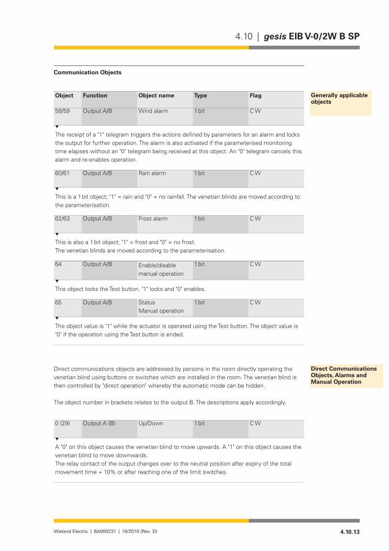
4.10.13Wieland Electric | BA000231 | 10/2010 (Rev. D)
4.10 | gesis EIB V-0/2W B SP
Communication Objects
Object Function Object name Type Flag
58/59 Output A/B Wind alarm 1 bit C W
The receipt of a "1" telegram triggers the actions defined by parameters for an alarm and locks the output for further operation. The alarm is also activated if the parameterised monitoring time elapses without an "0" telegram being received at this object. An "0" telegram cancels this alarm and re-enables operation.
60/61 Output A/B Rain alarm 1 bit C W
This is a 1 bit object; "1" = rain and "0" = no rainfall. The venetian blinds are moved according to the parameterisation.
62/63 Output A/B Frost alarm 1 bit C W
This is also a 1 bit object; "1" = frost and "0" = no frost.The venetian blinds are moved according to the parameterisation.
64 Output A/B Enable/disable manual operation
1 bit C W
This object locks the Test button. "1" locks and "0" enables.
65 Output A/B Status Manual operation
1 bit C W
The object value is "1" while the actuator is operated using the Test button. The object value is "0" if the operation using the Test button is ended.
Direct communications objects are addressed by persons in the room directly operating the venetian blind using buttons or switches which are installed in the room. The venetian blind is then controlled by "direct operation" whereby the automatic mode can be hidden.
The object number in brackets relates to the output B. The descriptions apply accordingly.
0 (29) Output A (B) Up/Down 1 bit C W
A "0" on this object causes the venetian blind to move upwards. A "1" on this object causes the venetian blind to move downwards.The relay contact of the output changes over to the neutral position after expiry of the total movement time + 10% or after reaching one of the limit switches.
Generally applicable objects
Direct Communications Objects, Alarms and Manual Operation
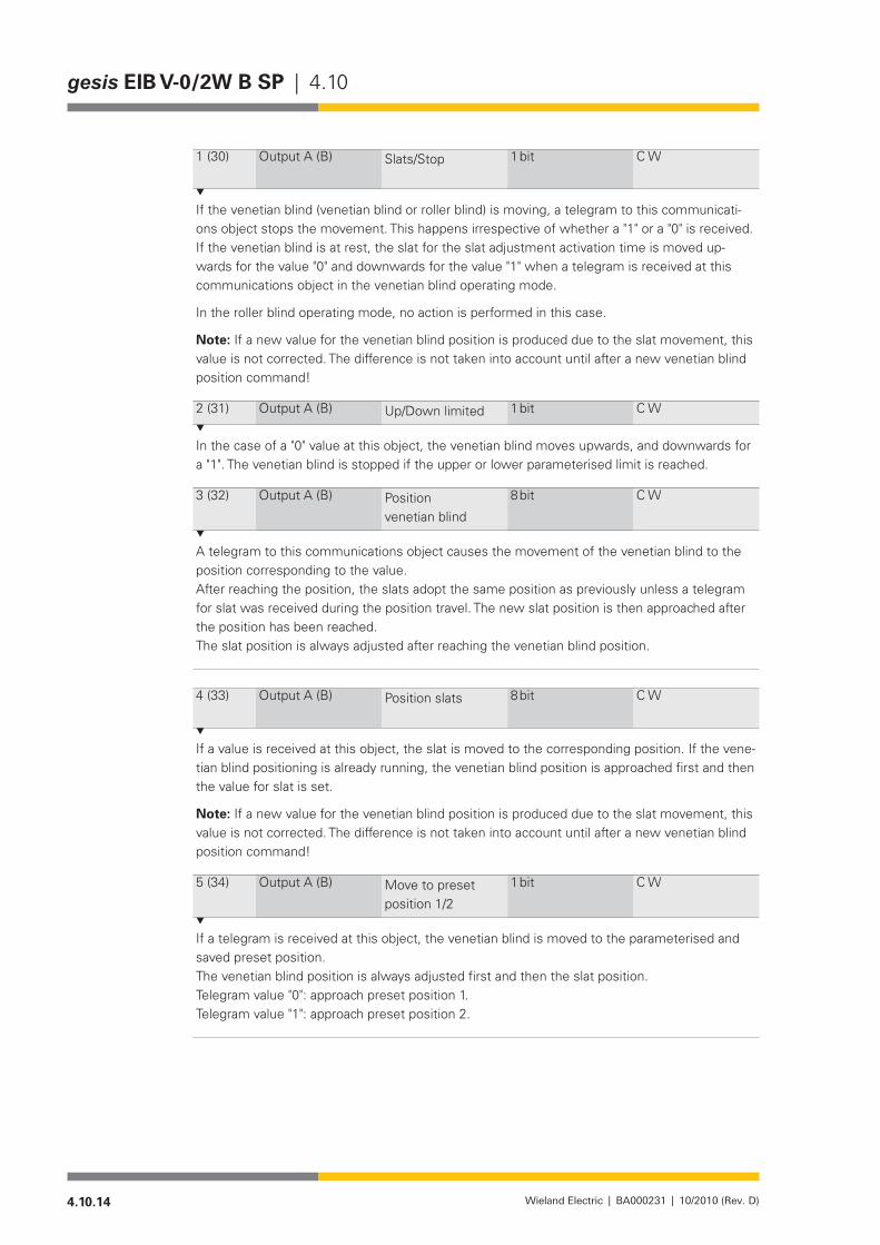
4.10.14 Wieland Electric | BA000231 | 10/2010 (Rev. D)
gesis EIB V-0/2W B SP | 4.10
1 (30) Output A (B) Slats/Stop 1 bit C W
If the venetian blind (venetian blind or roller blind) is moving, a telegram to this communicati-ons object stops the movement. This happens irrespective of whether a "1" or a "0" is received. If the venetian blind is at rest, the slat for the slat adjustment activation time is moved up-wards for the value "0" and downwards for the value "1" when a telegram is received at this communications object in the venetian blind operating mode.
In the roller blind operating mode, no action is performed in this case.
Note: If a new value for the venetian blind position is produced due to the slat movement, this value is not corrected. The difference is not taken into account until after a new venetian blind position command!
2 (31) Output A (B) Up/Down limited 1 bit C W
In the case of a "0" value at this object, the venetian blind moves upwards, and downwards for a "1". The venetian blind is stopped if the upper or lower parameterised limit is reached.
3 (32) Output A (B) Position venetian blind
8 bit C W
A telegram to this communications object causes the movement of the venetian blind to the position corresponding to the value.After reaching the position, the slats adopt the same position as previously unless a telegram for slat was received during the position travel. The new slat position is then approached after the position has been reached.The slat position is always adjusted after reaching the venetian blind position.
4 (33) Output A (B) Position slats 8 bit C W
If a value is received at this object, the slat is moved to the corresponding position. If the vene-tian blind positioning is already running, the venetian blind position is approached first and then the value for slat is set.
Note: If a new value for the venetian blind position is produced due to the slat movement, this value is not corrected. The difference is not taken into account until after a new venetian blind position command!
5 (34) Output A (B) Move to preset position 1/2
1 bit C W
If a telegram is received at this object, the venetian blind is moved to the parameterised and saved preset position.The venetian blind position is always adjusted first and then the slat position.Telegram value "0": approach preset position 1.Telegram value "1": approach preset position 2.
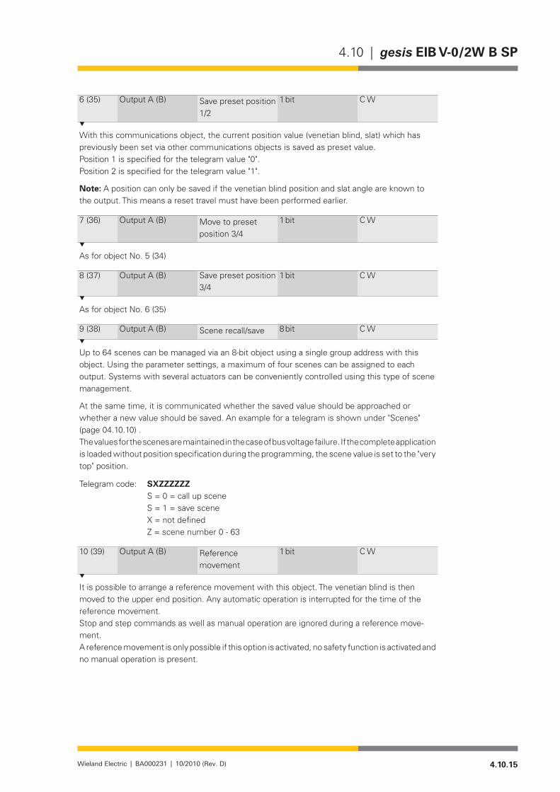
4.10.15Wieland Electric | BA000231 | 10/2010 (Rev. D)
4.10 | gesis EIB V-0/2W B SP
6 (35) Output A (B) Save preset position 1/2
1 bit C W
With this communications object, the current position value (venetian blind, slat) which has previously been set via other communications objects is saved as preset value.Position 1 is specified for the telegram value "0".Position 2 is specified for the telegram value "1".
Note: A position can only be saved if the venetian blind position and slat angle are known to the output. This means a reset travel must have been performed earlier.
7(36) Output A (B) Move to preset position 3/4
1 bit C W
As for object No. 5 (34)
8(37) Output A (B) Save preset position 3/4
1 bit C W
As for object No. 6 (35)
9 (38) Output A (B) Scene recall/save 8 bit C W
Up to 64 scenes can be managed via an 8-bit object using a single group address with this object. Using the parameter settings, a maximum of four scenes can be assigned to each output. Systems with several actuators can be conveniently controlled using this type of scene management.
At the same time, it is communicated whether the saved value should be approached or whether a new value should be saved. An example for a telegram is shown under "Scenes" (page 04.10.10) .The values for the scenes are maintained in the case of bus voltage failure. If the complete application is loaded without position specification during the programming, the scene value is set to the "very top" position.
Telegram code: SXZZZZZZ S = 0 = call up scene S = 1 = save scene X = not defined Z = scene number 0 - 63
10 (39) Output A (B) Reference movement
1 bit C W
It is possible to arrange a reference movement with this object. The venetian blind is then moved to the upper end position. Any automatic operation is interrupted for the time of the reference movement.Stop and step commands as well as manual operation are ignored during a reference move-ment.A reference movement is only possible if this option is activated, no safety function is activated and no manual operation is present.
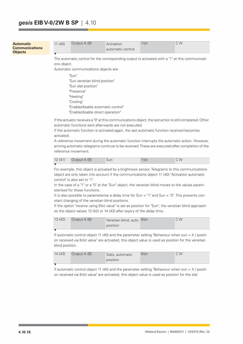
4.10.16 Wieland Electric | BA000231 | 10/2010 (Rev. D)
gesis EIB V-0/2W B SP | 4.10
11 (40) Output A (B) Activation automatic control
1 bit C W
The automatic control for the corresponding output is activated with a "1" at this communicati-ons object.Automatic communications objects are:
"Sun" "Sun venetian blind position" "Sun slat position" "Presence" "Heating" "Cooling" "Enable/disable automatic control" "Enable/disable direct operation"
If the actuator receives a "0" at this communications object, the last action is still completed. Other automatic functions sent afterwards are not executed.If the automatic function is activated again, the last automatic function received becomes activated.A reference movement during the automatic function interrupts the automatic action. However, arriving automatic telegrams continue to be received. These are executed after completion of the reference movement.
12 (41) Output A (B) Sun 1 bit C W
For example, this object is actuated by a brightness sensor. Telegrams to this communications object are only taken into account if the communications object 11 (40) "Activation automatic control" is also set to "1".In the case of a "1" or a "0" at the "Sun" object, the venetian blind moves to the values param-eterised for these functions.It is also possible to parameterise a delay time for Sun = "1" and Sun = "0". This prevents con-stant changing of the venetian blind positions.If the option "receive using 8 bit value" is set as position for "Sun", the venetian blind approach-es the object values 13 (42) or 14 (43) after expiry of the delay time.
13 (42) Output A (B) Venetian blind, auto. position
8 bit C W
If automatic control object 11 (40) and the parameter setting "Behaviour when sun = X / positi-on received via 8-bit value" are activated, this object value is used as position for the venetian blind position.
14 (43) Output A (B) Slats, automatic position
8 bit C W
If automatic control object 11 (40) and the parameter setting "Behaviour when sun = X / positi-on received via 8-bit value" are activated, this object value is used as position for the slat.
Automatic Communications Objects

4.10.17Wieland Electric | BA000231 | 10/2010 (Rev. D)
4.10 | gesis EIB V-0/2W B SP
15 (44) Output A (B) Presence 1 bit C W
This object is only activated if Automatic = "1" and the parameter "Automatic heating/cooling" is set.This object switches between the functions "automatic sun protection" and "automatic heating/cooling". The switching can be optimised using definable delay times. If the value "1" is sent by the presence detector, the venetian blind is controlled using the communications object "Sun". If the value "0" is sent, the venetian blind is controlled using the objects "Heating/Cooling" and "Sun".Attention: if the Heating and Cooling objects are both 1 or both 0, the output is only controlled using the automatic sun protection irrespective of the presence. Please also take account of this for the indicator in the status byte.
16 (45) Output A (B) Heating 1 bit C W
Incoming telegrams to this object are only observed if "Automatic = 1" is activated and there is a "0" in the "Presence" object.If the value "1" is received for the "Heating" object, the corresponding output moves to the respective parameterised values for "Behaviour when Heating = 1 and Sun = 1" and "Behaviour when Heating = 1 and Sun = "0".The movement is analogous for the "Cooling" object.If a "0" or a "1" is received at both "Heating/Cooling" objects, the automatic heating/cooling is deacti-vated and the output is controlled using the automatic sun protection.
17(46) Output A (B) Cooling 1 bit C W
Analogous to object No. 16
18(47) Output A (B) Enable/disable auto-matic control
1 bit C W
A "1" at this object locks (interrupts) the automatic operation. The control can now only be per-formed using the "direct" communications commands.The interruption is revoked with a "0" at this object and the automatic operation is resumed if necessary.
19 (48) Output A (B) Enable/disable direct operation
1 bit C W
A "1" at this object locks (interrupts) the direct operation. The control can now only be perfor-med using the automatic communications commands.The direct operation is enabled again with a "0".
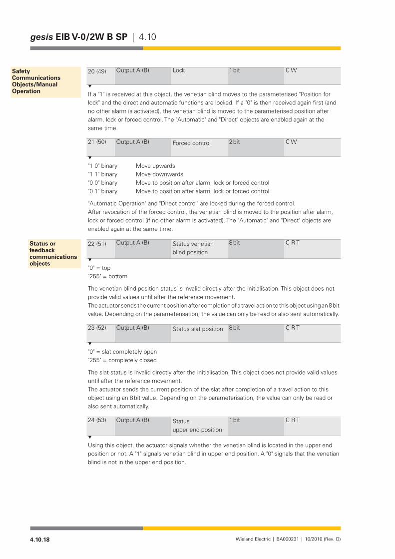
4.10.18 Wieland Electric | BA000231 | 10/2010 (Rev. D)
gesis EIB V-0/2W B SP | 4.10
20 (49) Output A (B) Lock 1 bit C W
If a "1" is received at this object, the venetian blind moves to the parameterised "Position for lock" and the direct and automatic functions are locked. If a "0" is then received again first (and no other alarm is activated), the venetian blind is moved to the parameterised position after alarm, lock or forced control. The "Automatic" and "Direct" objects are enabled again at the same time.
21 (50) Output A (B) Forced control 2 bit C W
"1 0" binary Move upwards"1 1" binary Move downwards"0 0" binary Move to position after alarm, lock or forced control"0 1" binary Move to position after alarm, lock or forced control
"Automatic Operation" and "Direct control" are locked during the forced control.After revocation of the forced control, the venetian blind is moved to the position after alarm, lock or forced control (if no other alarm is activated). The "Automatic" and "Direct" objects are enabled again at the same time.
22 (51) Output A (B) Status venetian blind position
8 bit C R T
"0" = top"255" = bottom
The venetian blind position status is invalid directly after the initialisation. This object does not provide valid values until after the reference movement.The actuator sends the current position after completion of a travel action to this object using an 8 bit value. Depending on the parameterisation, the value can only be read or also sent automatically.
23 (52) Output A (B) Status slat position 8 bit C R T
"0" = slat completely open"255" = completely closed
The slat status is invalid directly after the initialisation. This object does not provide valid values until after the reference movement.The actuator sends the current position of the slat after completion of a travel action to this object using an 8 bit value. Depending on the parameterisation, the value can only be read or also sent automatically.
24 (53) Output A (B) Status upper end position
1 bit C R T
Using this object, the actuator signals whether the venetian blind is located in the upper end position or not. A "1" signals venetian blind in upper end position. A "0" signals that the venetian blind is not in the upper end position.
Safety Communications Objects/Manual Operation
Status or feedback communications objects

4.10.19Wieland Electric | BA000231 | 10/2010 (Rev. D)
4.10 | gesis EIB V-0/2W B SP
25 (54) Output A (B) Status lower end position
1 bit C R T
Using this object, the actuator signals whether the venetian blind is located in the lower end position or not. A "1" signals venetian blind in lower end position. A "0" signals that the venetian blind is not in the lower end position.
26 (55) Output A (B) Status object for operation
1 bit C R T
"0": Operation enabled"1": Operation locked
The venetian blind actuator sends the information to this communications object whether the operation via the "Direct" and "Automatic" communications objects is enabled or locked. The op-eration is locked if either any of the "Safety" functions (e.g. weather alarm, lock, forced control) has been activated or if the venetian blind actuator has been switched to manual operation or if the direct and automatic operation are locked simultaneously via communications objects. The operation status is sent after any change.
27(56) Output A (B) Status Automatic control
1 bit C R T
The actuator signals that the automatic mode is activated with a "1" to this object.For example, if the output is moved to a safe position due to a wind alarm, the object value is set to "0". The automatic operation cannot influence the output.
28(57) Output A (B) Status byte 8 bit C W
This byte indicates a specific status in each bit. If several bits are set ("1"), the output reacts according to the parameterisation (prioritisation, lock, behaviour in the case of alarm etc.).
Key table (all values not listed are not defined!
Bit activated deactivated7 H/C automatic 1 06 Sun automatic 1 05 Wind alarm 1 04 Rain alarm 1 03 Frost alarm 1 02 Forced control 1 01 Lock 1 0
0Manual operation via Test button on the device
1 0
Parameterisation
The parameters in "A/B Safety" and "A/B Manual Operation" refer to the complete venetian blind actuator and its outputs. All other parameters refer to a single output.
The default settings are the settings in the as-delivered state. All settings are reset to the default settings after a reset of the device (program download, ETS).
NOTEDefault settings appear in bold.

4.10.20 Wieland Electric | BA000231 | 10/2010 (Rev. D)
gesis EIB V-0/2W B SP | 4.10
Parameter Possible setting
Wind alarm 1/2 ActivatedDeactivated
Rain alarm 1/2 ActivatedDeactivated
Frost alarm 1/2 ActivatedDeactivated
Monitoring time for wind alarm 1min/…/5 min/…/60min0 min = without cyclical monitoring
Monitoring time for rain alarm 1min/…/5 min /…/60min0 min = without cyclical monitoring
Monitoring time for frost alarm 1min/…/5 min /…/60min0 min = without cyclical monitoring
"0 min" for the monitoring time X means in each case that the cyclical monitoring is not acti-vated.
Priority sequence of weather alarm 1. Wind – 2. Rain – 3. Frost1. Wind – 2. Frost – 3. Rain1. Rain – 2. Wind – 3. Frost1. Rain – 2. Frost – 3. Wind1. Frost – 2. Rain – 3. Wind1. Frost – 2. Wind – 3. Rain
A behaviour for the venetian blind can be defined for each alarm (see "Behaviour in the event of wind / rain / frost alarm"). If two or three weather alarms are triggered simultaneously, the priority order determines which pattern the venetian blind should behave in accordance with. The respective higher prioritised alarm actions are executed for as long as the corresponding alarm is present. After the end of the highest priority alarm, the next alarm is checked accord-ing to the priority order and its actions are executed if necessary.
Priority sequence of safety functions 1. Weather alarm–2. lock–3. Forced control1. Lock–2. Weather alarm–3. Forced control1. Forced control–2. Lock–3. Weather alarm1. Forced control–2. Weather alarm–3. Lock1. Lock–2. Forced control–3. Weather alarm1. Weather alarm–2. Forced control–3. Lock
Parameter Possible setting
Manual Operation enabled enable/disable via communications object
In the case of "enable", manual operation at the device and EIB/KNX is possible.
Reset of manual operation by long keystroke by long keystroke and via time
“A/B Safety” parameters
“A/B Manual Operation” parameters
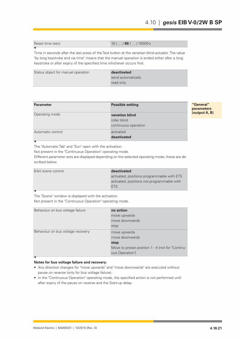
4.10.21Wieland Electric | BA000231 | 10/2010 (Rev. D)
4.10 | gesis EIB V-0/2W B SP
Reset time (sec) 10/…/60/…/10000s
Time in seconds after the last press of the Test button at the venetian blind actuator. The value "by long keystroke and via time" means that the manual operation is ended either after a long keystroke or after expiry of the specified time whichever occurs first.
Status object for manual operation deactivated send automaticallyread only
Parameter Possible setting
Operating mode venetian blind roller blind continuous operation
Automatic control activated deactivated
The "Automatic Tab" and "Sun" open with the activation.Not present in the "Continuous Operation" operating mode.Different parameter sets are displayed depending on the selected operating mode; these are de-scribed below.
8-bit scene control deactivatedactivated, positions programmable with ETSactivated, positions not programmable with ETS
The "Scene" window is displayed with the activation.Not present in the "Continuous Operation" operating mode.
Behaviour on bus voltage failure no action move upwards move downwards stop
Behaviour on bus voltage recovery move upwards move downwards stopMove to preset position 1 - 4 (not for "Continu-ous Operation")
Notes for bus voltage failure and recovery:Any direction changes for "move upwards" and "move downwards" are executed without •pause on reverse (only for bus voltage failure).In the "Continuous Operation" operating mode, the specified action is not performed until •after expiry of the pause on reverse and the Start-up delay.
“General” parameters (output A, B)

4.10.22 Wieland Electric | BA000231 | 10/2010 (Rev. D)
gesis EIB V-0/2W B SP | 4.10
Only for "Venetian blind" operating mode: •
Number of slat steps for adjustment 0 - 100 % (1 - 20)
1/…/5/…/20
Slat adjustment time in ms for adjustment 0 - 100 %
100/…/500/…/60000
If the slat adjustment time is greater than the total adjustment time of the slat (see below), the slat adjustment time is limited to the total adjustment time. In doing so, the selected value of the adjustment time is not changed.
Slats total adjustment time in ms for a com-plete turn, > or = 100 %
100/…/1000/…/60000
See drawing on page 4.10.7 for details.
Fan out in in lower end position (0 - 50) 0/…/50
The step times are summarised to a movement time and executed.
Adjustment of previous slat angle after posi-tioning
yesno
Only for "Roller Blinds" operating mode: •
Move upwards in lower end position, time in ms (0 - 10000)
0/…/10000
Only for "Continuous Operation" operating mode: •
Time switch function deactivatedStart-up delayRun-out delayON and Run-out delayautomatic time switch
On delay in seconds (0 - 1000)Off delay in seconds (0 - 1000)On-time in seconds (0 - 1000)
0/…/1000(Ondelay,OnandOffdelay)0/…/1000(Offdelay,OnandOffdelay)0/…/1000(Automatictimeswitch)
Notes:In the case of a direction change, the Start-up delay and pause on reverse are summed.•The times of the time switch function are ignored in manual mode and in the case of an •alarm.
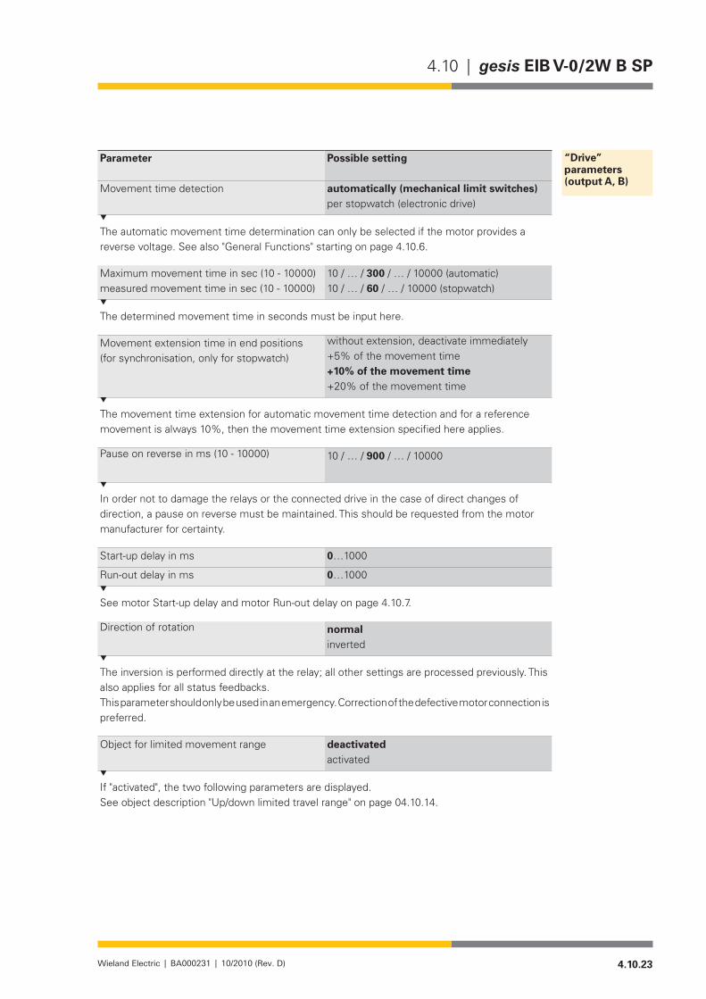
4.10.23Wieland Electric | BA000231 | 10/2010 (Rev. D)
4.10 | gesis EIB V-0/2W B SP
Parameter Possible setting
Movement time detection automatically (mechanical limit switches)per stopwatch (electronic drive)
The automatic movement time determination can only be selected if the motor provides a reverse voltage. See also "General Functions" starting on page 4.10.6.
Maximum movement time in sec (10 - 10000)measured movement time in sec (10 - 10000)
10/…/300/…/10000(automatic)10/…/60/…/10000(stopwatch)
The determined movement time in seconds must be input here.
Movement extension time in end positions (for synchronisation, only for stopwatch)
without extension, deactivate immediately+5% of the movement time +10% of the movement time +20% of the movement time
The movement time extension for automatic movement time detection and for a reference movement is always 10%, then the movement time extension specified here applies.
Pause on reverse in ms (10 - 10000) 10/…/900/…/10000
In order not to damage the relays or the connected drive in the case of direct changes of direction, a pause on reverse must be maintained. This should be requested from the motor manufacturer for certainty.
Start-up delay in ms 0…1000
Run-out delay in ms 0…1000
See motor Start-up delay and motor Run-out delay on page 4.10.7.
Direction of rotation normalinverted
The inversion is performed directly at the relay; all other settings are processed previously. This also applies for all status feedbacks.This parameter should only be used in an emergency. Correction of the defective motor connection is preferred.
Object for limited movement range deactivated activated
If "activated", the two following parameters are displayed.See object description "Up/down limited travel range" on page 04.10.14.
“Drive” parameters (output A, B)
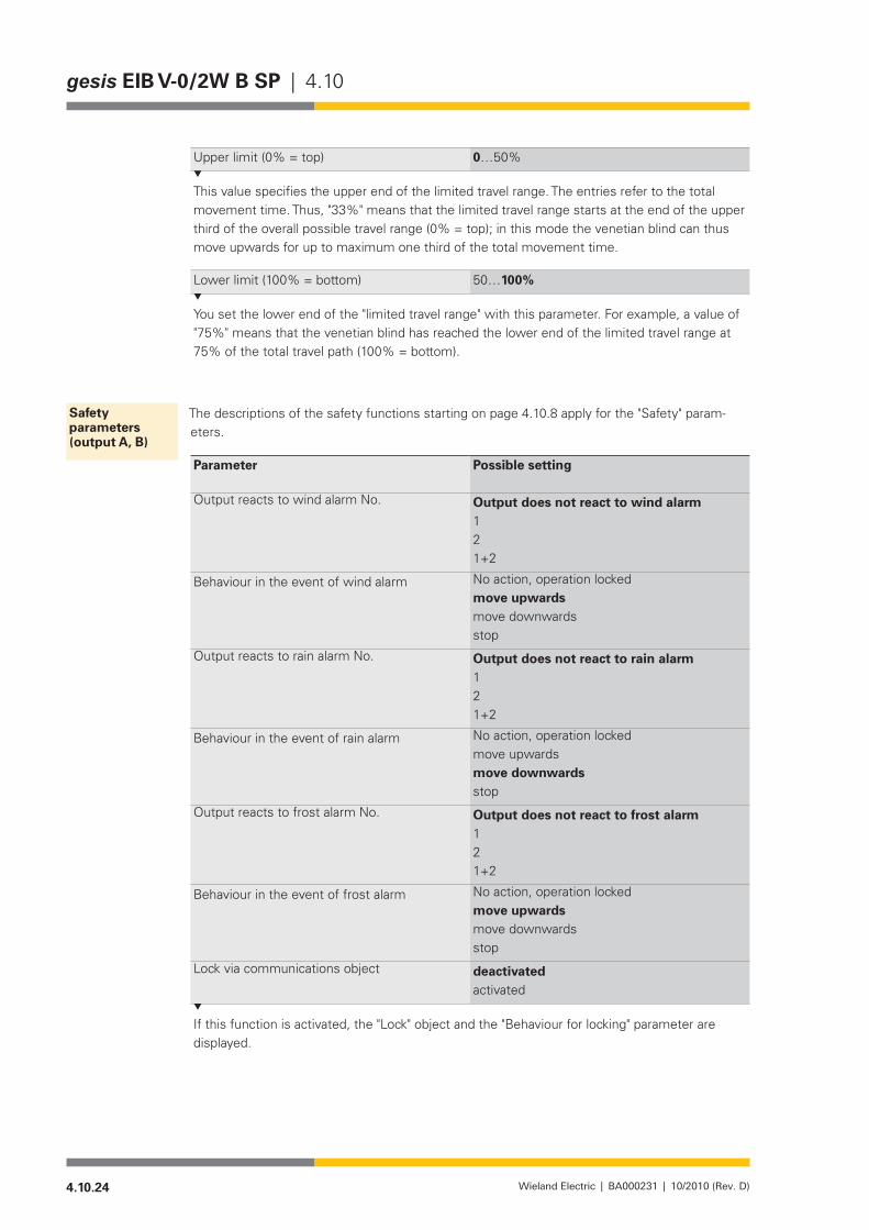
4.10.24 Wieland Electric | BA000231 | 10/2010 (Rev. D)
gesis EIB V-0/2W B SP | 4.10
Upper limit (0% = top) 0…50%
This value specifies the upper end of the limited travel range. The entries refer to the total movement time. Thus, "33%" means that the limited travel range starts at the end of the upper third of the overall possible travel range (0% = top); in this mode the venetian blind can thus move upwards for up to maximum one third of the total movement time.
Lower limit (100% = bottom) 50…100%
You set the lower end of the "limited travel range" with this parameter. For example, a value of "75%"meansthatthevenetianblindhasreachedthelowerendofthelimitedtravelrangeat75%ofthetotaltravelpath(100%=bottom).
The descriptions of the safety functions starting on page 4.10.8 apply for the "Safety" param-eters.
Parameter Possible setting
Output reacts to wind alarm No. Output does not react to wind alarm121+2
Behaviour in the event of wind alarm No action, operation lockedmove upwards move downwards stop
Output reacts to rain alarm No. Output does not react to rain alarm121+2
Behaviour in the event of rain alarm No action, operation lockedmove upwards move downwards stop
Output reacts to frost alarm No. Output does not react to frost alarm121+2
Behaviour in the event of frost alarm No action, operation lockedmove upwards move downwards stop
Lock via communications object deactivatedactivated
If this function is activated, the "Lock" object and the "Behaviour for locking" parameter are displayed.
Safety parameters (output A, B)
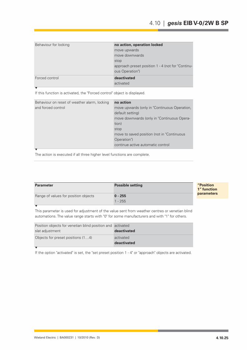
4.10.25Wieland Electric | BA000231 | 10/2010 (Rev. D)
4.10 | gesis EIB V-0/2W B SP
Behaviour for locking no action, operation locked move upwards move downwards stop approach preset position 1 - 4 (not for "Continu-ous Operation")
Forced control deactivatedactivated
If this function is activated, the "Forced control" object is displayed.
Behaviour on reset of weather alarm, locking and forced control
no actionmove upwards (only in "Continuous Operation, default setting)move downwards (only in "Continuous Opera-tion)stopmove to saved position (not in "Continuous Operation")continue active automatic control
The action is executed if all three higher level functions are complete.
Parameter Possible setting
Range of values for position objects 0 - 255 1 - 255
This parameter is used for adjustment of the value sent from weather centres or venetian blind automations. The value range starts with "0" for some manufacturers and with "1" for others.
Position objects for venetian blind position and slat adjustment
activated deactivated
Objectsforpresetpositions(1…4) activated deactivated
If the option "activated" is set, the "set preset position 1 - 4" or "approach" objects are activated.
“Position 1” function parameters
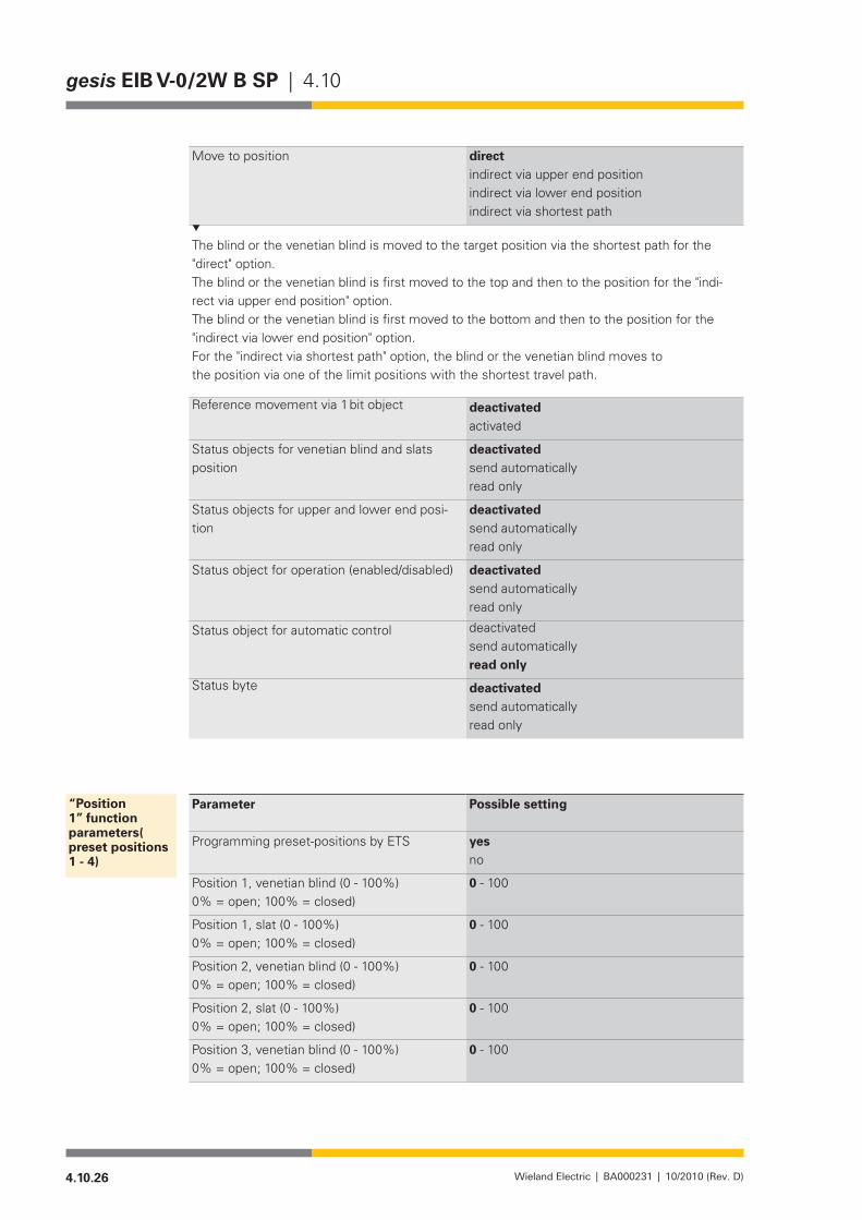
4.10.26 Wieland Electric | BA000231 | 10/2010 (Rev. D)
gesis EIB V-0/2W B SP | 4.10
Move to position direct indirect via upper end position indirect via lower end position indirect via shortest path
The blind or the venetian blind is moved to the target position via the shortest path for the "direct" option.The blind or the venetian blind is first moved to the top and then to the position for the "indi-rect via upper end position" option.The blind or the venetian blind is first moved to the bottom and then to the position for the "indirect via lower end position" option.For the "indirect via shortest path" option, the blind or the venetian blind moves tothe position via one of the limit positions with the shortest travel path.
Reference movement via 1 bit object deactivated activated
Status objects for venetian blind and slats position
deactivated send automaticallyread only
Status objects for upper and lower end posi-tion
deactivated send automaticallyread only
Status object for operation (enabled/disabled) deactivated send automaticallyread only
Status object for automatic control deactivated send automaticallyread only
Status byte deactivated send automaticallyread only
Parameter Possible setting
Programming preset-positions by ETS yesno
Position 1, venetian blind (0 - 100%) 0% = open; 100% = closed)
0 - 100
Position 1, slat (0 - 100%) 0% = open; 100% = closed)
0 - 100
Position 2, venetian blind (0 - 100%) 0% = open; 100% = closed)
0 - 100
Position 2, slat (0 - 100%) 0% = open; 100% = closed)
0 - 100
Position 3, venetian blind (0 - 100%) 0% = open; 100% = closed)
0 - 100
“Position 1” function parameters( preset positions 1 - 4)
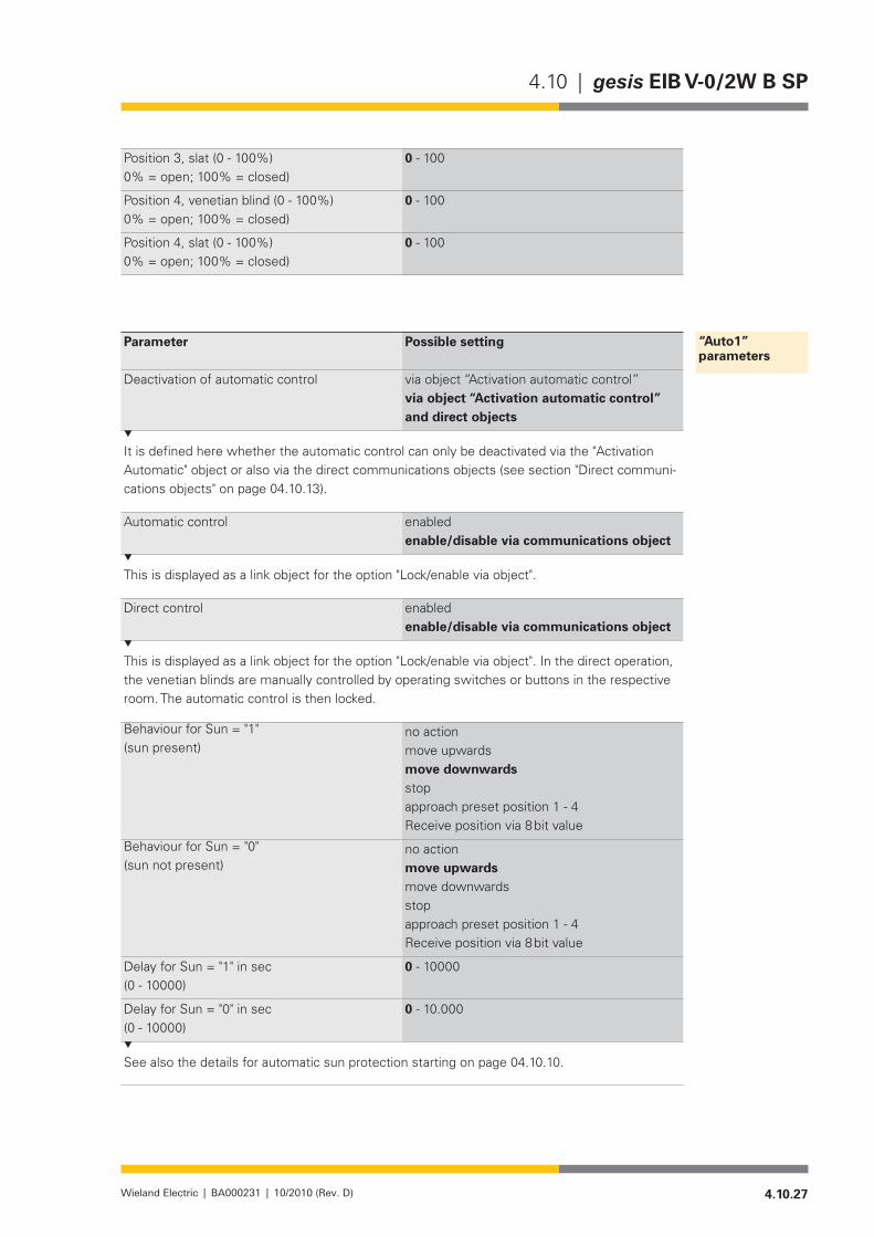
4.10.27Wieland Electric | BA000231 | 10/2010 (Rev. D)
4.10 | gesis EIB V-0/2W B SP
Position 3, slat (0 - 100%) 0% = open; 100% = closed)
0 - 100
Position 4, venetian blind (0 - 100%) 0% = open; 100% = closed)
0 - 100
Position 4, slat (0 - 100%) 0% = open; 100% = closed)
0 - 100
Parameter Possible setting
Deactivation of automatic control via object “Activation automatic control”via object “Activation automatic control” and direct objects
It is defined here whether the automatic control can only be deactivated via the "Activation Automatic" object or also via the direct communications objects (see section "Direct communi-cations objects" on page 04.10.13).
Automatic control enabled enable/disable via communications object
This is displayed as a link object for the option "Lock/enable via object".
Direct control enabled enable/disable via communications object
This is displayed as a link object for the option "Lock/enable via object". In the direct operation, the venetian blinds are manually controlled by operating switches or buttons in the respective room. The automatic control is then locked.
Behaviour for Sun = "1" (sun present)
no action move upwards move downwards stop approach preset position 1 - 4Receive position via 8 bit value
Behaviour for Sun = "0"(sun not present)
no action move upwards move downwards stop approach preset position 1 - 4Receive position via 8 bit value
Delay for Sun = "1" in sec(0 - 10000)
0 - 10000
Delay for Sun = "0" in sec(0 - 10000)
0 - 10.000
See also the details for automatic sun protection starting on page 04.10.10.
“Auto1” parameters
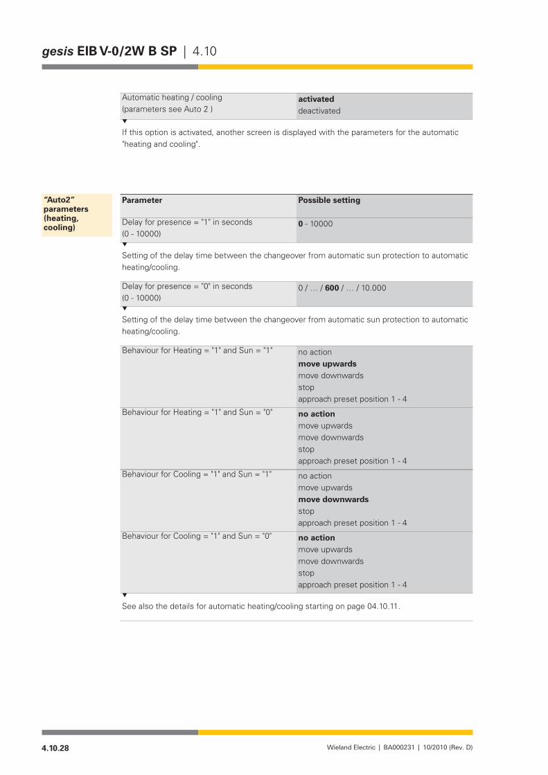
4.10.28 Wieland Electric | BA000231 | 10/2010 (Rev. D)
gesis EIB V-0/2W B SP | 4.10
Automatic heating / cooling(parameters see Auto 2 )
activated deactivated
If this option is activated, another screen is displayed with the parameters for the automatic "heating and cooling".
Parameter Possible setting
Delay for presence = "1" in seconds(0 - 10000)
0 - 10000
Setting of the delay time between the changeover from automatic sun protection to automatic heating/cooling.
Delay for presence = "0" in seconds(0 - 10000)
0/…/600/…/10.000
Setting of the delay time between the changeover from automatic sun protection to automatic heating/cooling.
Behaviour for Heating = "1" and Sun = "1" no action move upwards move downwards stop approach preset position 1 - 4
Behaviour for Heating = "1" and Sun = "0" no action move upwards move downwards stop approach preset position 1 - 4
Behaviour for Cooling = "1" and Sun = "1" no action move upwards move downwards stop approach preset position 1 - 4
Behaviour for Cooling = "1" and Sun = "0" no action move upwards move downwards stop approach preset position 1 - 4
See also the details for automatic heating/cooling starting on page 04.10.11.
“Auto2” parameters (heating, cooling)

4.10.29Wieland Electric | BA000231 | 10/2010 (Rev. D)
4.10 | gesis EIB V-0/2W B SP
Parameter Possible setting
Scene assignment 1 / 2 / 3 / 4 activateddeactivated
Each output can be integrated in up to 8 (4) scenes with one group address. In total, these 2x4 scenes can be selected from 64 scenes. The calling up or new creation of the scenes is performed via an 8-bit telegram. See also the details under "Scene" starting on page 04.10.10.
Output A is linked to scene No.1- scene No. 64
Venetian blind position (0 - 100%)(0% = top; 100% = bottom)
0 - 100
Slats position (0 - 100%)(0% = open; 100% = closed)
0 - 100
If the operating mode "Continuous Operation" is activated, the "Status" function is displayed with the following parameters.
Parameter Possible setting
Status objects for movement upwards and movement downwards
deactivated send automaticallyread only
Status object for operation(enabled/disabled)
deactivated send automaticallyread only
Status byte deactivated send automaticallyread only
“Scene 1/ Scene 2“ parameters
Parameters for the status in the “Continuous Operation” operating mode

4.10.30 Wieland Electric | BA000231 | 10/2010 (Rev. D)
gesis EIB V-0/2W B SP | 4.10


�����������������������������������������������������
�����������������������������������������������������������������������������������������������������������
�����������������������