
Hydropower and Water Turbines Renewable Energy Resources Hydropower.

Ministry of Energy Norwegian Water
of Georgia Resources and Energy
Directorate
COST BASE
FOR SMALL HYDROPOWER PLANTS IN GEORGIA
< 13 MEGAWATT
(price level 1st January 2015)
2016

PREFACE
In 2013 the Norwegian Water Resources and Energy Directorate (NVE) entered into a cooperation with the Ministry of Energy of Georgia and the National Environmental Agency of Georgia, with the purpose of developing an inventory of all hydropower potential in Georgia, including development and construction costs. The cooperation necessitated a step-wise approach, where the following steps were necessary:
• Preparation and quality control of historical hydrometeorological data
• Land use mapping and preparation of a digital elevation model (DEM)
• Preparation of a national runoff map for Georgia
• Compilation of cost data for hydropower development
• Calculation of the hydropower potential and associated costs
This manual, which has been prepared by Georgian (Gross Energy Group) and Norwegian (Norconsult AS) consultants in cooperation with the Ministry of Energy of Georgia and NVE, contains relevant cost data for hydropower development in Georgia. Hopefully the manual may serve as a useful guide to potential investors in renewable energy in Georgia, as well as a tool for the government for assessment and prioritization of the hydropower development.

TABLE OF CONTENTS
1 GENERAL CHAPTER ................................................................................................... 1
1.1 GENERAL .............................................................................................................................. 1 1.1.1 INTRODUCTION ............................................................................................................................. 1 1.1.2 HISTORY ......................................................................................................................................... 1 1.1.3 CONTENT AND USE OF THE REPORT ........................................................................................ 1 1.1.4 PRICE LEVEL.................................................................................................................................. 2
1.2 STRATEGY FOR SMALL HYDROPOWER PLANTS ........................................................... 2 1.2.1 INVESTMENT ADVANTAGES ........................................................................................................ 3 1.2.2 ENERGY POLICY ........................................................................................................................... 3
1.3 PROCESSES FOR HYDROPOWER DEVELOPMENT IN GEORGIA ................................. 3 1.3.1 ENVIRONMENTAL IMPACT ASSESSMENT .................................................................................. 3 1.3.2 LAND TRANSFER ........................................................................................................................... 3 1.3.3 CONSTRUCTION PERMIT ............................................................................................................. 3 1.3.4 GENERATION LICENSE ................................................................................................................. 3 1.3.5 INTERCONNECTION AGREEMENT .............................................................................................. 4
2 BUILDING AND ENGINEERING WORK ....................................................................... 5
2.1 GENERAL .............................................................................................................................. 5 2.1.1 SCOPE OF DELIVERY ................................................................................................................... 5 2.1.2 EVALUATION OF OVERHEADS ..................................................................................................... 6 2.1.3 PRICE VARIANCE .......................................................................................................................... 6 2.1.4 CONSIDERATIONS RELATING TO THE VALUE OF DEVELOPERS' PERSONAL EFFORTS ..... 6
2.2 DAMS ..................................................................................................................................... 9 2.2.1 SMALL RIPRAP DAMS ................................................................................................................... 9 2.2.2 CONCRETE DAMS ......................................................................................................................... 9 2.2.3 TIMBER CRIB DAMS .................................................................................................................... 11
2.3 INTAKE STRUCTURES ....................................................................................................... 17 2.4 POWER STATIONS ............................................................................................................. 20 2.4.1 SURFACE POWER STATIONS .................................................................................................... 20 2.4.2 UNDERGROUND POWER STATIONS ......................................................................................... 20
2.5 PENSTOCKS, CHANNELS ................................................................................................. 22 2.5.1 PENSTOCK FOUNDATIONS ........................................................................................................ 22 2.5.2 PIPE TRENCHES .......................................................................................................................... 24 2.5.3 CHANNELS ................................................................................................................................... 26
2.6 GEOTECHNICAL ENGINEERING ...................................................................................... 29 2.6.1 TUNNEL MINIMUM CROSS-SECTION ........................................................................................ 29 2.6.2 LARGE-HOLE DRILLING .............................................................................................................. 29 2.6.3 ROCK DRILLING ........................................................................................................................... 32
2.7 TRANSPORT FACILITIES ................................................................................................... 32 2.7.1 TEMPORARY ROADS FOR CONSTRUCTION PURPOSES ....................................................... 32
3 ELECTROTECHNICAL WORKS ................................................................................. 34
3.1 GENERAL ............................................................................................................................ 34 3.1.1 POWER FACTOR (COSΦ) .......................................................................................................... 34
3.2 GENERATOR ...................................................................................................................... 35 3.3 TRANSFORMERS ............................................................................................................... 38 3.4 SWITCHGEAR AND CONTROL SYSTEMS ....................................................................... 40 3.5 POWER LINES .................................................................................................................... 43
4 MECHANICAL ENGINEERING ................................................................................... 44
4.1 GENERAL ............................................................................................................................ 44 4.1.1 SCOPE OF DELIVERY ................................................................................................................. 44 4.1.2 PRICE ESTIMATE ......................................................................................................................... 44
4.2 TURBINES ........................................................................................................................... 45 4.2.1 PELTON TURBINES ..................................................................................................................... 47 4.2.2 FRANCIS TURBINES .................................................................................................................... 48 4.2.3 KAPLAN/BULB TURBINES ........................................................................................................... 49 4.2.4 OTHER SOLUTIONS AND TURBINES ......................................................................................... 50
4.3 GATES ................................................................................................................................. 55 4.3.2 ROLLER GATE .............................................................................................................................. 55 4.3.3 SLIDING GATE .............................................................................................................................. 56
4.3.4 FLAP GATES................................................................................................................................. 56 4.3.5 RUBBER GATES ........................................................................................................................... 57
4.4 INTAKE SCREENS .............................................................................................................. 61 4.5 LIFTING EQUIPMENT ......................................................................................................... 63 4.5.1 TRAVELLING CRANE ................................................................................................................... 63 4.5.2 ELECTRIC HOIST W/ELECTRIC TRAVELLER ............................................................................ 63 4.5.3 ALTERNATIVE LIFTING EQUIPMENT ......................................................................................... 63 4.5.4 MOBILE CRANES ......................................................................................................................... 63
4.6 INTAKE SCREEN RAKES ................................................................................................... 66 4.7 PIPES ................................................................................................................................... 67 4.7.1 PE PIPES ...................................................................................................................................... 68 4.7.2 GRP PIPES ................................................................................................................................... 68 4.7.3 SPIRAL WELDED STEEL PIPES .................................................................................................. 69 4.7.4 SEAMLESS STEEL PIPES ........................................................................................................... 69 4.7.5 DUCTILE CAST-IRON PIPES ....................................................................................................... 69 4.7.6 WOODEN PIPES ........................................................................................................................... 70
5 COMPLETE ELECTROMECHANICAL DELIVERIES .................................................. 75
5.1 GENERAL ............................................................................................................................ 75 5.1.1 SCOPE OF DELIVERY ................................................................................................................. 75
5.2 COMPLETE SMALL HYDROPOWER PLANT UNIT FROM 500–13,000 KW .................... 75 5.2.1 PRICE ESTIMATE ......................................................................................................................... 75 5.2.2 SMALL HYDROPOWER PLANT GENERATORS ......................................................................... 76
5.3 MICRO AND MINI POWER UNITS UP TO 500 KW ........................................................... 76 5.3.1 PRICE ESTIMATE ......................................................................................................................... 76 5.3.2 MICRO AND MINI POWER UNITS ............................................................................................... 76 5.3.3 PELTON TURBINES ..................................................................................................................... 79 5.3.4 FRANCIS TURBINES .................................................................................................................... 79 5.3.5 KAPLAN ........................................................................................................................................ 79 5.3.6 OTHER TYPES OF TURBINES .................................................................................................... 79

1
1 GENERAL CHAPTER
1.1 GENERAL
1.1.1 INTRODUCTION
This manual has been prepared to provide tools for calculating average foreseeable contractor costs (building-related work) and supplier costs (mechanical and electrical equipment) for small hydroelectric power plants with an early phase generating capacity of up to 13,000 kW. These costs will depend on a number of conditions, which may vary from power plant to power plant, and consequently requires the user possesses sound technical knowledge. This applies in particular to the building-related work associated with the hydropower plant. The manual is a supplement to our Cost Base for larger hydropower projects (> 13,000kW). 1.1.2 HISTORY
Up to now former Soviet Union standards, as well as the quarterly published manual issued
by the Construction evaluation union, has been used in Georgia.
Norconsult AS (Norway) has been assigned the task of preparation the Cost Base for Small
Hydropower Plants for Georgia (price level 1 January 2015) by the Norwegian Water
Resources and Energy Directorate (NVE) as a task in the agreement between NVE and
Ministry of Energy (MOE) of Georgia. The final version is a result of joint review and
corrections by NVE (also consulting Norconsult) and MOE (assisted by Georgian consultant
Gross Energy Group).
Current manual represents a very smart tool for the calculation of hydropower development
in Georgia. Maintenance and upgrading of the Cost Base in future will be undertaken when
judged necessary.
Power plants with a generating capacity of 0-13 MW are often divided into:
Micro power plants which are power plants with a capacity of up to 100 kW
Mini power plants which are power plants with a capacity of between 100 kW and 1 MW
Small hydropower plants are power plants with a capacity of between 1 MW and 13 MW
1.1.3 CONTENT AND USE OF THE REPORT
The report has been divided into three main chapters:
• Construction and civil engineering works
• Electrotechnical engineering works.
• Mechanical engineering works
The report aims to present costs under "normal" conditions, and is intended to be used in the
early planning stages to quickly establish the approximate cost of a project and to compare
the costs of different hydro projects.
Most prices are presented in the form of graphs with associated text.

2
1.1.4 PRICE LEVEL
The prices in the report are as of 1 January 2015. All prices are stated in United States
Dollars, USD.
1.2 STRATEGY FOR SMALL HYDROPOWER PLANTS
Over the past several years, the Georgian Government has undertaken an ambitious
program to modernise and liberalise its economy. Institutional reforms have included
privatising large state-owned entities, reducing the number of taxes and tax rates, improving
tax and fiscal administration, restructuring license requirements, simplifying customs and
border formalities, and generally undertaking efforts to make it easier to do business in
Georgia.
It can be boldly stated that Georgia is a “Hydro Powered” country. On average 85% of total
country generation comes from domestic hydro power plants. Georgia’s natural wealth is
comprised principally of water and water resources, and its hydroelectric potential per capita
ranks among the world’s greatest. It is a reliable transit country and regional energy hub with
significant transit potential for delivering resources from the Caspian region to international
markets.
Implementation of potential renewable projects is a top priority for the Ministry and its
sources make a major contribution to sustainable development of our country. Growing
demand in our and neighbouring countries on electricity strongly encourages potential
investors to take full advantage of new approaches and investment opportunities in energy
sector of Georgia.
Government's effort to attract foreign direct investments resulted in creating an investor-
friendly environment by offering green-field projects based on the Build-Own-Operate (BOO)
principal, attractive export markets, free third party access to the grid and efficient legal and
regulatory framework.
Liberal tax legislation, Double Taxation Avoidance Treaties with OECD member countries,
rapidly expandable export market, simplified procedures, and strong support and
commitment aiming at developing of renewable energy sources from the Government of
Georgia create favourable business climate for the potential investors.
Georgia's energy independence is an integral component of the country's priorities.
Currently, energy mix dependency of Georgia on thermal and external sources is 75%-80%
that can only be reduced by development of renewable energy resources, primarily hydro
and energy efficiency. Our aim is to increase energy security and support development of
green economy. Renewable sector represents the only domestic natural resource addressing
Georgia’s domestic needs.
Our goal is to further develop east-west and north-south energy transportation infrastructure
in order to increase transit capacity of the country. Additional goals are to improve social and
economic condition by attracting new investments in renewable energy projects, improve
economic and social condition by creating new jobs and new opportunities for people, further
develop modern and reliable infrastructure creating energy independence for the Country
and strengthen co-operation with the international organizations in order to accelerate
integration of the country into European and Euro-Atlantic organizations.

3
1.2.1 INVESTMENT ADVANTAGES
• Build-Own-Operate (BOO) principle;
• Deregulated Energy Sector;
• Simplified Procedures;
• Diversified & Expanding export markets, including EU;
• No fee for the connection to the transmission grid;
• Carbon Credits Trading;
• New HPPs have priority access to the capacity on the new interconnection to Turkey;
• Generation and Export activities are exempted from VAT
• 15 year PPA for total generation of power plant during September-April period
1.2.2 ENERGY POLICY
• Diversification of the energy supply resources, optimal utilization and reserve creation
of the Georgian energy resources;
• Exploitation of the Georgia’s renewable energy resources;
• Gradual rapprochement of Georgian legislation with EU legislation;
• Georgian energy market development and improvement of the energy trade
mechanisms;
• Increasing the role of Georgia as a regional transit country;
• Georgia – clean energy production and regional centre for the energy trade;
• Creation of unified approach on Energy Efficiency and its execution;
• Consideration of the environmental issues during energy projects implementation;
• Improvement of the service level and consumers rights protection.
1.3 PROCESSES FOR HYDROPOWER DEVELOPMENT IN GEORGIA
1.3.1 ENVIRONMENTAL IMPACT ASSESSMENT
Approved by Ministry of Environment and Natural resources protection in no more than 60 days for public hearing and up to 20 days for approval by the ecology committee.
1.3.2 LAND TRANSFER
If the plant site is State-owned, GoG will lease to the investor on the long-term (99-year) basis or transfer the land plot to the investor for a nominal fee (the nominal fee is set by the local municipalities for the purpose of privatization and it is closer to market price) through the direct sale procedure for land privatization. 1.3.3 CONSTRUCTION PERMIT
Issued by Ministry of Economic and Sustainable Development of Georgia for HPP of 2 MW or more and by agencies of local self-governance. It takes 30 days for verification of Land ownership, maximum 20 days for approval of technical design (including Environmental Impact Permit), and up to 10 days for issuance of Permit. 1.3.4 GENERATION LICENSE
Issued by the Georgian National Energy and Water Supply Regulatory Commission (“NGEWRC”), is the legal basis for power generation activity and should be obtained prior to

4
the operation of units of 13MW or more. It has a granting period of approximately 30 days, including 5 days to confirm application completeness. 1.3.5 INTERCONNECTION AGREEMENT
Newly constructed plants need to make interconnection agreement with the owner of Transmission line/grid. The connecting is free of charge and transmission rates are set by the GEWRC

5
2 BUILDING AND ENGINEERING WORK
2.1 GENERAL
2.1.1 SCOPE OF DELIVERY
The cost base includes costs as stated for each construction and engineering section.
For the last period, there has been tendency of price decrease, though there are some prices
that have not changed compared to the prices given in the construction material cost book,
which provides information on regulated market prices.
In the Cost Base for Small Hydropower Plants general costs such as rigging, overheads, and
operational (henceforth referred to as "overheads" or "rigging") expenses are excluded in all
building-related cost components and must be added to the total project cost. Generally, the
additional rigging cost that should be added is 30% of the total cost of all other works.
The following costs have not been included and must be evaluated for each project:
• Transport and temporary roads for construction purposes.
• Rehabilitation of land and waters (forest clearing, routes, landfills, land adjustment)
• Other general costs: Represent additional costs of 10-15% and usually include the
following:
- Surveying and preparation of engineering basis (maps, profiles, etc.)
- Stream gauging and hydrologic assessments
- Environmental surveys
- Impact assessments
- Soil surveys
- Planning and engineering. Depending on conditions by the dam, intake, penstock
(incline), power station (depth to rock, etc.).
- Administration, construction management, quality control
• Taxes and fees (value added tax, investment tax).
• Builder costs (land acquisition, valuation, compensation, financing expenses)
• Unforeseen costs. It is generally recommended to add 15-20% to all cost elements to
cover any unforeseen costs.

6
2.1.2 EVALUATION OF OVERHEADS
It is imperative to note that overheads may vary considerably. Costs for small hydropower
plants are usually in the region of 10-60%, and in special cases even higher. This must be
evaluated on a project to project basis, and depends on the location and available
infrastructure. A greater distance to villages/towns results in higher overheads due to
increased transport, travel and accommodation costs. The choice of contract and contractor
will also affect the overhead costs, as larger contractors tends towards low unit costs at the
expense of more overheads, and vice versa for smaller contractors. The total price is usually
similar, however. Furthermore, the nature of the work is an important factor. Mainly a single
type of work, a long tunnel for instance, leads to lower overheads than complicated work
requiring more coordination.
2.1.3 PRICE VARIANCE
The presented unit prices for individual construction parts are weighted averages based on collated prices from tendering documents and published index values. Consequently, each unit is assumed to be of "normal" accessibility and difficulty (unless where stated otherwise). In practice a range of factors influence actual unit prices, and price variations are to be expected, between projects and for different construction parts of the same project.
This is accounted for by the provided uncertainty ranges. Simply put, work under very favourable conditions may result in 20% lower unit prices, whereas work in adverse conditions may increase unit prices by 30%, for instance.
2.1.4 CONSIDERATIONS RELATING TO THE VALUE OF DEVELOPERS' PERSONAL
EFFORTS
General
“Personal efforts” are the opportunities a developer has to make a personal contribution,
performing parts of the project work and reducing the need for hired assistance, thus
reducing overall costs. There are many types of viable personal efforts, usually relating to
preparatory and building-related work. Turbines and other similar equipment must usually be
supplied by one or several professional suppliers, however.
In many cases it will not be allowed with personal efforts in public power plant projects. Nor
will large private power plants be particularly suitable for personal efforts as implementation
requires substantial capacity and well organised efforts over a period of time. It would difficult
to coordinate the developer's personal efforts with the work of the contractor. However,
private landowners and other stakeholders may participate in the project in the normal
commercial manner, such as contractor activities.
There are greater opportunities for personal efforts in smaller, private projects (mini and
micro power plants). Such projects are often owned by one or a few landowners, and the
power plant is often constructed with a great deal of idealism. Personal efforts in smaller
projects can significantly reduce external costs, and may be necessary to implement the
project at an acceptable price.

7
Concept phase
Landowners and owners of waterfall rights are often of the opinion that it should be possible
to build a power plant at the site, and they want to develop the idea and assess the
feasibility. The first step is often to obtain written information about the procedure from the
authorities and then to contact a neutral and experienced consultant on water resource
management. It may also be a good idea to hire a consultant for a few hours for a
professional evaluation of the project, particularly with regard to the potential size of the
project and whether there are any special restrictions (e.g. environmental protection). The
personal effort may in this respect consist of procuring the relevant information, studying the
procedures, and learning a little bit about others projects. Before proceeding, the rights for
the entire development should be established.
Project Development
The landowner can do a fair bit of preparatory work; obtain maps, specify ownership, inform
neighbours about the prospective project, register their thoughts and opinions, inform the
municipal authorities about the concept and register the local authorities' viewpoints. If there
are several landowners, it may be necessary to organise landowner. It may be important to
agree in advance to investigate the development, even if issues of ownership, etc. have not
been fully resolved. These are time-consuming activities which the landowner(s) can do
himself/themselves (and which they often do best). In this phase, it is often natural to contact
external consultants, such as professional developers. This will often result in an
independent evaluation of the project, and can result in inspections and meetings where the
landowners participate and contribute. If the project is viable, the next phase will be to
develop more specific plans and outline the project's main features.
Obtaining a basic design
This is a phase in which the landowner can do some work, possibly in cooperation with a
consultant. He can conduct surveys, establish and estimate ground conditions at the location
of the potential dam, penstocks and power station, and indicate the locations on a map. The
landowner can obtain permits from the authorities and dig test pits or ditches to determine
ground conditions.
Furthermore, the landowner can photograph the river system at the assumed location of the
dam and power station during different water flows; preferably from drought to major flood
conditions. The photographs should be taken at different seasons and specify the date when
they were taken. The photos should be digital and be taken from the same angle, preferably
quite far away, at a distance of a few hundred metres, depending on the size of the
project/river. It is important to take photos that provide an overview of the site.
Hydrological surveys, technical pre-engineering, environmental surveys, licence applications
Professional consultants will usually conduct these activities. The landowner may prepare a
draft of most of the work relating to very small mini- and micro power plants, in accordance
with official guidelines. If necessary assistance may be acquired from a hired consultant for
inspection and supplementation.

8
Preparation of inquiries and budget prices of turbines and equipment is often at the top of a
developer's to-do-list. However, the above-mentioned activities should be carried out before
it is possible to obtain realistic data for actual quotes for the installation.
When a licence or an exception from the obligation to acquire a licence has been granted
When a licence has been granted, implementation of the actual project will start. Detailed
solutions for various parts of the installation are then prepared on the basis of the terms and
conditions in the licence, surveys, etc., and tenders for equipment and building-related work
are prepared. After this, a plan for the environment and landscape is prepared and a detailed
safety plan is drawn up. The content of the detailed plans is to a large extent dictated by the
licence. Moreover, the plans must be prepared in accordance with official guidelines. It is
recommended that this work is conducted by a consultant with expertise in the fields of
environmental technology and hydroelectricity. There are many engineers offering such
consulting services. Choosing a consultant with expertise in and experience from many
different installations will provide optimal solutions and predictable and safe implementation
of the project both technically and financially.
Funding
The developer or the landowner must provide the necessary funding.
Implementation and construction
For mini or small hydropower plants, the landowner will be able to assist with preparatory
work, ensuring accessibility for contractors and equipment by clearing the forest, constructing
access roads, trenches, suitable sites for temporary accommodation modules and workshop
containers, etc.
It will be necessary to ensure that the required permits are obtained, as well as follow-up of
administrative issues vis-à-vis public authorities, connection to the public power grid, etc.
Operations
During the operating period, it is often natural that the landowner should be responsible for
daily supervision. This will primarily involve ensuring that the intake is clean, and possibly
regulating the upstream dams to adjust the flow of water to the power plant in question.
Power sales
Power sales to the grid must be formalised through agreements and the amount of energy
must be measured automatically. In some cases, some of the energy may be used for
personal consumption, and energy may be supplied by the grid during shutdown periods.
Agreements for- and organisation of such conditions may be individual and may be
contingent on the ownership and the size of the power plant.
9
2.2 DAMS
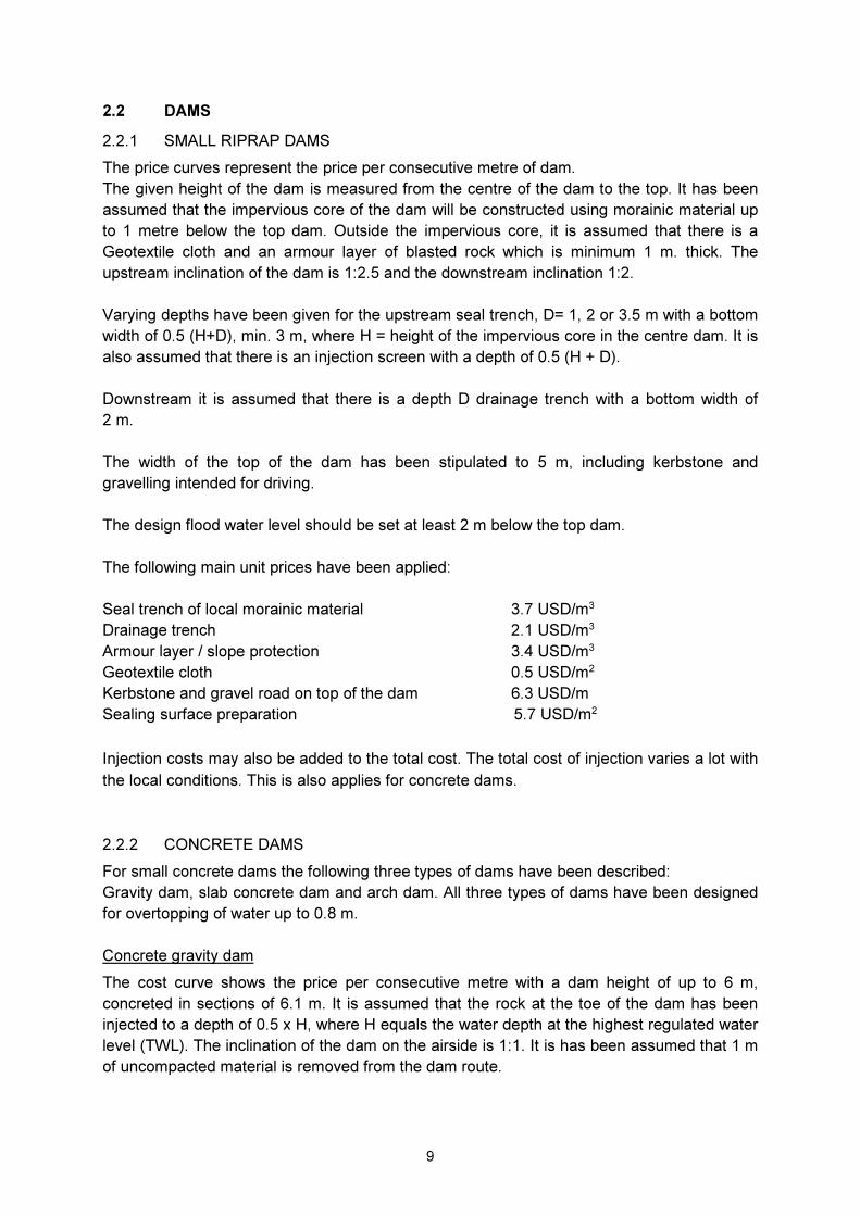
2.2.1 SMALL RIPRAP DAMS
The price curves represent the price per consecutive metre of dam.
The given height of the dam is measured from the centre of the dam to the top. It has been
assumed that the impervious core of the dam will be constructed using morainic material up
to 1 metre below the top dam. Outside the impervious core, it is assumed that there is a
Geotextile cloth and an armour layer of blasted rock which is minimum 1 m. thick. The
upstream inclination of the dam is 1:2.5 and the downstream inclination 1:2.
Varying depths have been given for the upstream seal trench, D= 1, 2 or 3.5 m with a bottom
width of 0.5 (H+D), min. 3 m, where H = height of the impervious core in the centre dam. It is
also assumed that there is an injection screen with a depth of 0.5 (H + D).
Downstream it is assumed that there is a depth D drainage trench with a bottom width of
2 m.
The width of the top of the dam has been stipulated to 5 m, including kerbstone and
gravelling intended for driving.
The design flood water level should be set at least 2 m below the top dam.
The following main unit prices have been applied:
Seal trench of local morainic material 3.7 USD/m3
Drainage trench 2.1 USD/m3
Armour layer / slope protection 3.4 USD/m3
Geotextile cloth 0.5 USD/m2
Kerbstone and gravel road on top of the dam 6.3 USD/m
Sealing surface preparation 5.7 USD/m2
Injection costs may also be added to the total cost. The total cost of injection varies a lot with
the local conditions. This is also applies for concrete dams.
2.2.2 CONCRETE DAMS
For small concrete dams the following three types of dams have been described:
Gravity dam, slab concrete dam and arch dam. All three types of dams have been designed
for overtopping of water up to 0.8 m.
Concrete gravity dam
The cost curve shows the price per consecutive metre with a dam height of up to 6 m,
concreted in sections of 6.1 m. It is assumed that the rock at the toe of the dam has been
injected to a depth of 0.5 x H, where H equals the water depth at the highest regulated water
level (TWL). The inclination of the dam on the airside is 1:1. It is has been assumed that 1 m
of uncompacted material is removed from the dam route.

10
The following main unit prices have been applied:
Digging, removal of uncompacted material 1.1 USD/m3
Foundation preparation (fine scaling) 2.6 USD/m2
Formwork 10.4 USD/m2
Reinforcement 0.6 USD/kg
Concrete 48.0 USD/m3
Slab concrete dam with inclined slab
A slab concrete dam may be more economical than a gravity dam above a certain height. A
slab concrete dam will be particularly advantageous in areas where it is expensive to have
concrete delivered.
For the slab concrete dam, the cost curve shows the price per consecutive metre of dam,
concreted in sections of 5 m. The injection screen goes down to a depth of 0.5 x H, where H
represents the water depth at the highest regulated water level (TWL). The inclination of the
front slab is between 1:0.80-0.95, and the inclination of the supporting slab 1:0.25-1.0. The
steepest inclinations are for the tallest dams. The slab concrete dam has not been insulated
on the air side. It is assumed that uncompacted material is removed at 2 m width in the dam
route, and depth to rock is 0-1m.
The following unit prices have been applied:
Digging, stripping of uncompacted material 1.1 USD/m3
Foundation on rock front slab (incl. scaling and sealing) 110.0 USD/m2
Formwork 10.4 USD/m2
Reinforcement 0.6 USD/kg
Concrete 48.0 USD/m3
Concrete arch dam
An arch dam might be the best solution for narrow locations. A concrete arch dam is
characterised by a low mass volume compared to its height. Arch dams are therefore very
practical at suitable dam locations.
In the cost curve, the minimum thickness of an arch dam has been set at 0.6 m. The dam is
uninsulated and functions as a flood route. Other associated costs have not been included,
such as for discharge gates, pedestrian paths, larger abutments, etc. Rock that has been
removed from the toe of the dam is replaced by concrete.
The following unit prices have been applied as a basis:
Foundation preparation (scaling and concrete) 80.0 USD/m2
Formwork 10.4 USD/m2
Reinforcement 0.6 USD/kg
Concrete 48.0 USD/m3

11
2.2.3 TIMBER CRIB DAMS
At sites with easy access to rocks, timber and qualified manpower, timber crib dams are
sometimes more economical than concrete dams and traditional riprap dams. Moreover,
timber crib dams can be constructed with an overflow without major changes to the
construction. This is an advantage compared to more traditional riprap dams. However,
timber is a living building material with a relatively short lifespan.
For the timber crib dam the cost curve shows the price per consecutive metre of dam. The
dam includes a seal trench and timber plank sealing on the water side.
The price of the timber crib dam does not include overflow. However, the cost developments
with timber plank overflow will be relatively similar. The curve is based on empirical figures
with normal unit prices for the various building and engineering works. The costs will largely
be determined by local conditions.

12

13

14

15

16
17
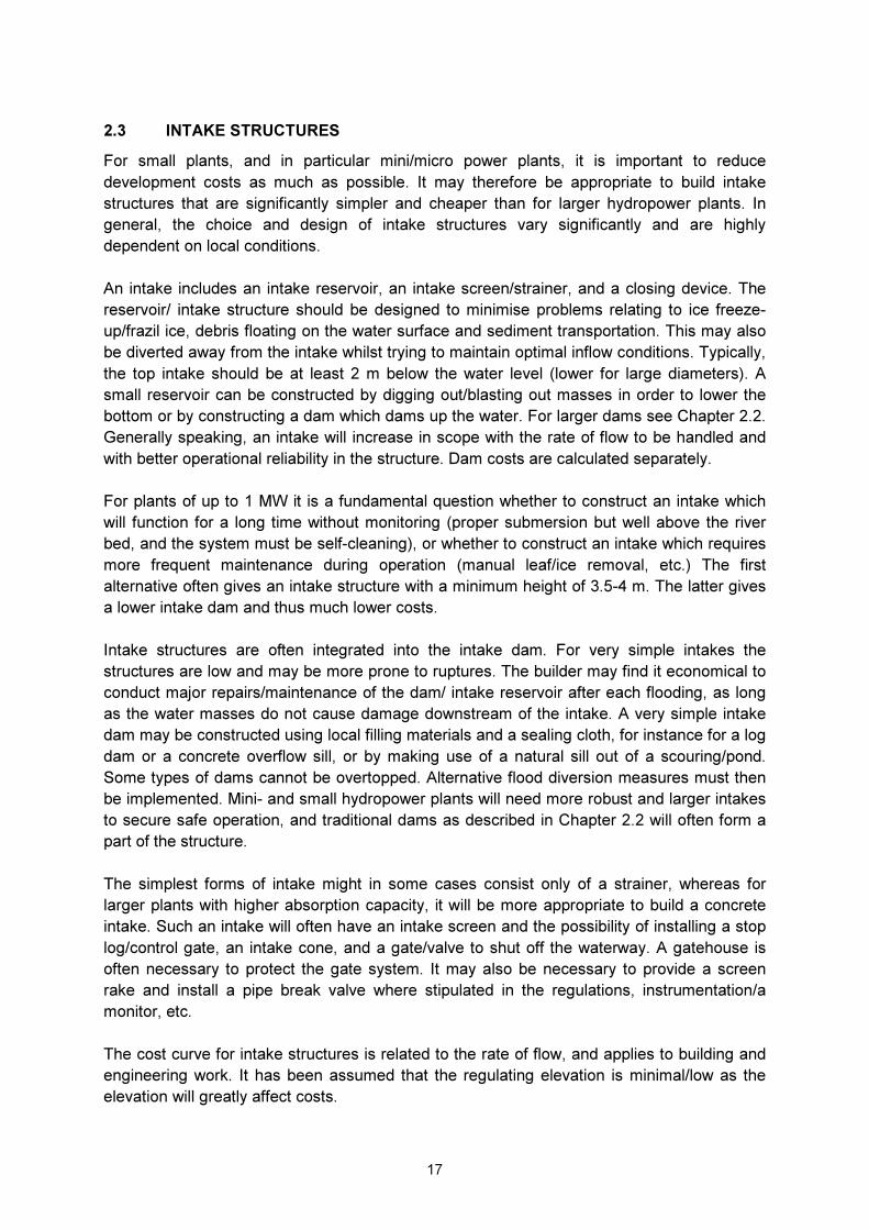
2.3 INTAKE STRUCTURES
For small plants, and in particular mini/micro power plants, it is important to reduce
development costs as much as possible. It may therefore be appropriate to build intake
structures that are significantly simpler and cheaper than for larger hydropower plants. In
general, the choice and design of intake structures vary significantly and are highly
dependent on local conditions.
An intake includes an intake reservoir, an intake screen/strainer, and a closing device. The
reservoir/ intake structure should be designed to minimise problems relating to ice freeze-
up/frazil ice, debris floating on the water surface and sediment transportation. This may also
be diverted away from the intake whilst trying to maintain optimal inflow conditions. Typically,
the top intake should be at least 2 m below the water level (lower for large diameters). A
small reservoir can be constructed by digging out/blasting out masses in order to lower the
bottom or by constructing a dam which dams up the water. For larger dams see Chapter 2.2.
Generally speaking, an intake will increase in scope with the rate of flow to be handled and
with better operational reliability in the structure. Dam costs are calculated separately.
For plants of up to 1 MW it is a fundamental question whether to construct an intake which
will function for a long time without monitoring (proper submersion but well above the river
bed, and the system must be self-cleaning), or whether to construct an intake which requires
more frequent maintenance during operation (manual leaf/ice removal, etc.) The first
alternative often gives an intake structure with a minimum height of 3.5-4 m. The latter gives
a lower intake dam and thus much lower costs.
Intake structures are often integrated into the intake dam. For very simple intakes the
structures are low and may be more prone to ruptures. The builder may find it economical to
conduct major repairs/maintenance of the dam/ intake reservoir after each flooding, as long
as the water masses do not cause damage downstream of the intake. A very simple intake
dam may be constructed using local filling materials and a sealing cloth, for instance for a log
dam or a concrete overflow sill, or by making use of a natural sill out of a scouring/pond.
Some types of dams cannot be overtopped. Alternative flood diversion measures must then
be implemented. Mini- and small hydropower plants will need more robust and larger intakes
to secure safe operation, and traditional dams as described in Chapter 2.2 will often form a
part of the structure.
The simplest forms of intake might in some cases consist only of a strainer, whereas for
larger plants with higher absorption capacity, it will be more appropriate to build a concrete
intake. Such an intake will often have an intake screen and the possibility of installing a stop
log/control gate, an intake cone, and a gate/valve to shut off the waterway. A gatehouse is
often necessary to protect the gate system. It may also be necessary to provide a screen
rake and install a pipe break valve where stipulated in the regulations, instrumentation/a
monitor, etc.
The cost curve for intake structures is related to the rate of flow, and applies to building and
engineering work. It has been assumed that the regulating elevation is minimal/low as the
elevation will greatly affect costs.

18
Costs relating to screens, gates, screen rakes etc. are not included in the building-related
costs. These have been included in Chapter 4, Mechanical Engineering. However, costs for
the intake cone and a simple superstructure are included. The cost curve is based on
empirical figures with normal unit prices for the various building and engineering work.

19

20
2.4 POWER STATIONS
Building and engineering costs for power stations are presented in a cost curve for surface
power stations.
2.4.1 SURFACE POWER STATIONS
The costs of surface power stations are given as a function of discharge; in fig 2.4.1
There are, however, great variations in the empirical figures. This is because the power
stations are very different in terms of location, size and general standard of the plant. The
costs also vary according to the choice made between crane rails/removable roof,
vertical/horizontal-axis unit, the number of units, and foundation on rock/uncompacted
material. In general, it is the choice of turbine type/elevation head, which is the most
important and determines the design of the power station. Consequently, the costs have
been presented as a function of the elevation head and absorption capacity.
For plants around 1 MW it is a fundamental question whether to construct a power station
which will function without daily monitoring (typical power company) or, for instance, a power
station where the owner lives close by and is able to monitor the station on a daily basis. The
prices in the enclosed curves are for stations with a generator capacity of > 1MW.
2.4.2 UNDERGROUND POWER STATIONS
Mini, micro and small power plants with a capacity below 2-3 MW are not suitable for
construction underground/inside mountains. For small hydropower plants with a higher
output, the costs are determined on the basis of volume calculations from the cost base of
larger power plants. Despite the substantial variations in volume, it was attempted to
express the space requirements in a simple formula with the net height of fall (head), total
maximum water flow for the station and number of generators as parameters.
An indication of the blasted volume for underground power stations can be obtained by
applying the following formula:
Blast volume V = 78 x H0.5 x Q0.7 x n0.1
V = blasted volume, m3
H = net head, m.
Q = total maximum water flow, m3/s
n = number of power units
Estimations obtained by applying this formula will only be approximate. It is therefore
recommended that an outline is drawn up for each installation and that this is used as a basis
for calculating the blasted volume.
The total building-related engineering costs for underground power stations can be obtained
by multiplying the estimated mountain volume by a unit price comprising the costs of blasting
and construction of the power plant. Thus the unit price includes blasting, formwork,

21
reinforcement, concreting, preventive measures, masonry, plastering, painting, etc. An
evaluation of this, compared with empirical figures for construction of power stations in the
open has concluded that the unit price as of January 2015 can be set at 50 USD/m3 blasted
volume.
Unforeseen costs have not been included, and it is important to be aware that power station
prices vary significantly.
For underground power stations additional costs must be expected in connection with an
access tunnel with cable culvert, separate exit tunnel if required, escape room, etc. These
costs must be calculated separately, cf. Cost Base for Large Hydropower Plants, NVE.

22
2.5 PENSTOCKS, CHANNELS
Pipes and shutting devices are classified according to their damage potential in the event of
a rupture. The design requirements will reflect the damage potential. Consult official
guidelines.
Relevant types of pipes comprise spirally welded steel pipes, glass-fibre reinforced pipes of
unsaturated polyester (GRP), polyethylene pipes (PE) and ductile cast-iron pipes, and of
which GRP and cast-iron pipes are the most common.
In principle, the pipe foundations can either be buried or laid on foundation blocks. The
various pipe types have different foundation requirements, due to e.g. the type of material,
jointing method and how the impact forces are transferred. The most common combinations
are listed in the table below.
Type of pipe Buried On foundation
Steel pipes X
GRP pipes X X
PE pipes (X)
Ductile cast-iron pipes (x) (x)
For mini and micro plants it may be appropriate to lay the pipe on the ground and clip it to the
mountain. This is a simple construction method primarily used for small pipe diameter PE
pipes and steel pipes.
2.5.1 PENSTOCK FOUNDATIONS
Penstocks are buried or laid on foundations in the open.
Concrete foundations have different designs according to the forces they have to sustain, the
type of pipes, whether there is a support bar or whether they absorb impact forces in an
angular deflection in the penstock.
Anchorage support block
Support block
Penstock

23
2.5 PENSTOCKS, CHANNELS
Pipes and shutting devices are classified according to their damage potential in the event of
a rupture. The design requirements will reflect the damage potential. Consult official
guidelines.
Relevant types of pipes comprise spirally welded steel pipes, glass-fibre reinforced pipes of
unsaturated polyester (GRP), polyethylene pipes (PE) and ductile cast-iron pipes, and of
which GRP and cast-iron pipes are the most common.
In principle, the pipe foundations can either be buried or laid on foundation blocks. The
various pipe types have different foundation requirements, due to e.g. the type of material,
jointing method and how the impact forces are transferred. The most common combinations
are listed in the table below.
Type of pipe Buried On foundation
Steel pipes X
GRP pipes X X
PE pipes (X)
Ductile cast-iron pipes (x) (x)
For mini and micro plants it may be appropriate to lay the pipe on the ground and clip it to the
mountain. This is a simple construction method primarily used for small pipe diameter PE
pipes and steel pipes.
2.5.1 PENSTOCK FOUNDATIONS
Penstocks are buried or laid on foundations in the open.
Concrete foundations have different designs according to the forces they have to sustain, the
type of pipes, whether there is a support bar or whether they absorb impact forces in an
angular deflection in the penstock.
Costs for the different pipe types are presented in corresponding Chapter, Mechanical
Engineering.
Anchorage support block
Support block
Penstock

24
The design of pipe foundations will vary between the different types of pipes. In the following
the mean cost has been calculated. The foundation design is available from the supplier’s
installation instructions. Experienced consultants/contractors will also able to provide
assistance.
In the following, the estimated building and engineering costs of the penstocks include
foundations for an open penstock with the following assumptions:
Clearing the route, incl. rock removal/scaling 1.1 USD/m2
Digging, including loading and transport 1.8 USD/m3
Blasting 4.4 USD/m3
Foundation bolts 24.0 USD/each
Formwork (one-sided) 10.4 USD/m2
Reinforcement 0.6 USD/kg
Concrete (minor concreting) 70.0 USD/m3
In addition the following assumptions have been made:
Spacing between foundations: 9 m (steel) / 6 m (GRP)
Spacing between anchor logs: 60 m
Average foundation height from the ground
to the lower edge of the pipes: 1 m
The cost curves have been prepared for moderate slopes and good ground conditions.
The costs of penstock foundations depend to a large extent on the size of the anchor logs,
which must be dimensioned for water pressure, change of directions and pipe diameter.
Laying the anchor log at a horizontal bend in the rock cut/mountain trench will significantly
reduce the volume of concrete.
2.5.2 PIPE TRENCHES
Cost tables have been prepared for earth trenches and combined earth/rock trenches
for use in cost assessments of embedded pipes. The tables apply to trenches in a
relatively easy terrain.
GRP and cast iron pipes are most suitable for embedding. PE pipes may also be buried, but
then at low pressures and in easy terrain.
The drawing below shows a typical trench section for buried pipes:
PIPES
FOUNDATION MATERIAL
SURROUNDING FILLING MATERIAL DEPENDING ON PIPE TYPE
BACKFILLING LOCAL MATERIAL

25
The inclination of trench slopes has been set at 1:1 for earth trenches and 5:1 for rock
trenches. The bottom width of the trench is set as equal to the pipe diameter plus 1.0 m.
The costs in the tables include all contractor costs relating to digging, blasting and backfilling
from 300 mm above the pipes. Costs for reinforcement of trenches have not been included.
Refilling around the pipes is included in the prices. The prices are contingent on the use of
local material. If local material is not available, approximately 3.0 USD/m3 must be added for
delivery of the refilling material.
The price does not include construction of a temporary road to enable the digging of trenches
and installation of pipes. This must be calculated separately. The road construction costs
may be substantial, particularly if the terrain is steeper than 1:5.
The costs of rock trenches are set as equal to the cost of combined earth/rock trenches.
A terrain profile is required in order to be able to calculate the costs of pipe trenches, as well
as a thorough assessment of the local conditions. Uneven and/or steep terrain and difficult
access will have a great impact on the total costs.
Uncertainty in the cost estimations for relatively easy terrains is ± 30%.
The following unit prices have been used:
- Clearing of vegetation 1.1 USD/ m2
- Digging 1.1 USD/m3
- Rock removal/scaling 2.0 USD/m2
- Blasting 12.0 USD/m3
- Refilling material 3.6 USD/m3
(handling of local material)
- Backfilling 2.8 USD/m3
Trench costs (USD/rm). Trench width equals 1.5 m at the bottom.
Total trench depth:
1.5 m
2.0 m
3.0 m
4.0 m
Earth trench 30 40 70 110
Rock trench or combined
earth/rock trenches
40 55 85 120

26
Trench costs (USD/rm). Trench width equals 2.5 m at the bottom
Total trench depth:
1.5 m
2.0 m
3.0 m
4.0 m
Earth trench 35 50 85 130
Rock trench or combined
earth/rock trenches 60 80 120 170
2.5.3 CHANNELS
Where conditions allow, channels can be a good alternative to for example pipes. Curves are
prepared for uncompacted material and rock. It has been assumed that the material/masses
are impervious and that a lining/armour layer is unnecessary.
The estimated cost curves are based on work in an easy/ moderate terrain with the following
unit prices.
Clearing 1.1 USD/m2
Digging 1.1 USD/m 3
Blasting 4.4 USD/m3
Bottom width: 1-2 m
Pitching/tightening is not included.
Unforeseen costs are not included.

27

28

29
2.6 GEOTECHNICAL ENGINEERING
Rock work is sometimes necessary for small hydropower plants. Consequently, costs have
been estimated for the so-called "minimum cross-section", i.e. the least expensive tunnel
cross-section in relation to tunnel length.
Costs relating to large-hole drilling have also been estimated.
The cost of rock work depends to a large extent on the quality of the rock and the geological
conditions, which may vary considerably within a small area. Compared with easy rock
conditions, the cost of rock work can easily triple or quadruple if rock conditions are difficult,
and might in some places be even higher. Rock conditions can be variable and should be
considered carefully. Faults and cracks appearing as recessions in the terrain are often of a
poorer quality and one should avoid constructing tunnels or bore holes that run in the same
direction as these.
2.6.1 TUNNEL MINIMUM CROSS-SECTION
Tunnel costs for small hydropower plants are generally lower than for large projects. The
reason for this is that there are a number of minor players on the market for small
hydropower plants. Costs are estimated for cross-sections from 10-22 m2, run as
conventional tunnel operations.
A 40% rock protection supplement is included in the tunnel costs. This is normal for good
rock conditions. For small hydropower plants poor rock quality may exclude the tunnel option
as an alternative.
2.6.2 LARGE-HOLE DRILLING
There are three cost curves for large-hole drilling, showing good, medium and poor
drillability. The costs apply to drilling of pilot holes which are expanded (reamed) when the
drill bit is retracted.
Rock protection costs have not been included in the cost curves. Rock protection is not
normally conducted where rock conditions are good. However, this should be considered in
each case.
The drilling costs per metre are higher for a long hole than for a short one. Consequently, the
costs should be corrected by a factor linearly increasing from 1.0 to 1.25 for drilling lengths
starting at approximately 200 m up to 500 m.
Due to the uncertainty relating to the direction of the pilot hole, it is uncommon to drill more
than 500 m using this method. The maximum drilling length is currently up to 3,500 m.
However, much progress is being made in this field and such lengths require directional
steering of the drill bit, ref. Item. 1.1.3.

30

31

32
2.6.3 ROCK DRILLING
Fully electric-operated equipment and non-rotating drill string are two fundamental ideas
behind the development of a new technology for directional full profile drilling in hard rock.
Penstocks for hydropower plants can be drilled efficiently by remote controlled equipment
without adversely affecting the surrounding landscape. The technology is based on drilling
from the lowest end of the tunnel and up to the intake point at the highest point. Integrated
equipment for navigation and direction control makes it possible to drill in curve, and to reach
a predetermined location with high level of accuracy.
Equipment currently in operation can drill tunnels with diameters in the range of 0.7 m to 1.5
m over distances up to approximately 1.5 km, and over elevation differences up to
approximately 1 km.
Current drilling equipment is so far adapted for drilling over slopes of approximately 4 or
more degrees upwards. It is also possible to adapt the equipment for horizontal drilling. The
equipment is designed modularly in order to ensure flexible and efficient transportation and
rigging. Moreover it enables drilling operations without access roads.
Assignments are usually carried out at fixed costs depending on local conditions. For
planning purposes, the budget costs for complete drilling solutions with diameter 700 mm
can be assumed to be in the range of 1,400 USD to 1,600 USD per metre. For assignments
with diameters in the range of 1,200 mm to 1,500 mm the correspondingly cost is in the
range of 2,100 USD to 2,700 USD per metre.
It is often necessary to fully or partially line penstock tunnels. Specialist equipment is
available for lining work, and this is conducted from the lower end of the tunnel.
2.7 TRANSPORT FACILITIES
2.7.1 TEMPORARY ROADS FOR CONSTRUCTION PURPOSES
Empirical figures from various hydropower plants have been used as a basis for calculating
construction costs of temporary roads.
The costs will vary significantly with the topography and accessibility of the material, as well
as the standard of the temporary roads.
It was assumed that the temporary roads maintain a standard corresponding to (a Georgian)
forest road category 3.
The costs comprise a fully prepared road including planning, staking out, digging, blasting,
culverts, placing of base courses and gravelling. The scope of each operation such as
blasting and transport of material will have a significant impact on the price.
Costs for a fully prepared temporary road:
� Temporary road in easy terrain: 20 USD/running metre
� Temporary road in moderate terrain: 30 USD/running metre
� Temporary road in difficult terrain: 60 USD/running metre

33
Maintenance of temporary roads in the construction period is assumed to constitute
approximately 10% of the temporary road costs.
For small and simple bridge constructions, costs are estimated at approximately 500 USD/m2
roadway (decking).

34
3 ELECTROTECHNICAL WORKS
3.1 GENERAL
This chapter provides a basis for calculating the average foreseeable costs for electro-technical installations in small scale hydro plants. The attached price curves represent electrotechnical equipment for generators larger than 500 kW. Generators below 500 kW are often part of the “scope of work” for the turbine delivery and are therefore included in the price curves for turbines. For small scale hydropower plants it is important to keep the electrotechnical equipment as standardised as possible, provided it still delivers a certain level functionality and reliability. The price basis for this chapter assumes the control systems are based on the normally closed contact principle and asynchronous generator for generators smaller than 1,000 kVA. It is also assumed that the power station is to be connected to the distribution grid. The price basis upon which the curves are built is collected from mostly Georgian small scale power plants which has been tendered, contracted or built during the last five years, with an emphasis on the last year or two. In some instances budget prices for certain parts have been collected from different contractors. Some prices are highly variable; this may be explained by the fact that some contractors account for the possibility of additions to the scope of the work. As such, some contractors may suggest an overly expensive solution, whereas others may suggest a solution which differs somewhat from the design specifications in order to be perceived as cheaper than their competitors. Some budget prices may be misleading as they often lack design-, installation- and commissioning costs. Machine costs are highly controlled by the material costs on the international market, but even more so are the electrotechnical components. The price of general electrotechnical components appear to have increased moderately since 2010. The price increase of small scale generators is in the order of 0-10%, while power transformers have dropped in price by about 0-20%. In earlier versions of the Cost base for small-scale hydropower plants the costs of switchgear and control has been shown in two chapters with two corresponding graphs. These two main component groups are usually delivered in a combined package from the contractor. These costs have therefore been combined as one cost in the Cost base for small-scale hydropower plants 2015. Earlier costs of these components have been a bit high, and these have also been adjusted to fit the price level of 2015. The following main components are presented in this chapter:
� Generator � Power transformer � Control systems, including auxiliary power supply � Medium voltage switchgear � Power lines and grid connection
3.1.1 POWER FACTOR (COSΦ)
The output of electrotechnical components such as generators, power transformers and switchgear are given in kVA or MVA. In the Civil and Structural and Mechanical Chapters kW is often used as reference of output. In order to establish a context between the chapters in the Cost Base, the following electrotechnical components will be presented in kW as well. It is assumed a power factor of 0.85 for components above 2 MVA and 0.9 for components below 2 MVA. As an example the resulting kVA performance is 18 and 11 percent higher than the one given in kW for components above- and below 2 MVA respectively.

35
3.2 GENERATOR
Scope
The price in this chapter is based on air cooled generators with output from 500-2,000 kVA and water cooled generators within the 2,000-13,000 kVA range. Generators with lower output than 500 kVA are usually sold as a complete package together with the turbine etc. Most generators of this magnitude employ horizontal axis machines. In the price basis it has been assumed a support which can carry the turbine on a free shaft and with a natural flywheel mass and no flywheel. The prices are mainly based on generators with 375-1,000 rpm (synchronous). Slowly rotating generators are not standardised and are therefore more expensive. In figure 3.2.1a and 3.2.1b the prices are based on generators with rpm between 500 and 750 rpm. If the chosen generator has a higher rpm rating than 750 the price will be in the “higher price level”. If the generator rpm rating is below 500 rpm then the price will be in the “lower price level”. Aggregates with 375 rpm or less are not included in the Cost Base. In these cases it will usually be cost saving to use gears between the turbine and generator in order to increase the rpm. Ventilation
The power plants ventilation system needs to be designed in order to disperse the excess heat from the generator. This heat typically amounts to 2-3% of the nominal effect for an air cooled generator. During winter, some of this heat can be utilised to heat the machine room. Ventilation shafts for intake air should be designed with an appropriate air filter. Price Level
The utilised prices in this chapter are collected from Norwegian small scale power plants which has been tendered, contracted or built the last five years, and with an emphasis on the last two years. In the following paragraphs, some foreseeable price discrepancies for various changes / additions which are beyond the scope of this report have been outlined:
� Vertical alignment +10% � Asynchronous generator -5%
(Not relevant for generators larger than approximately 1,000 kVA) Generator voltage for machines with output lower than 1,500 kVA is usually 400 V. Machines with higher output than 2,500 kVA are usually high voltage machines, while the intermediate machines usually have 690 V. Voltage regulators are delivered as a standard component together with the generator.

36

37

38
3.3 TRANSFORMERS
Power transformers
This price basis includes transformers for grid connection to the distribution grid. Transformers below 1,600 kVA are usually standard oil filled distribution transformers. It is currently common to employ dry isolated transformers, even though these transformers are approximately 0-5% more expensive than standard oil filled distribution transformers. Larger transformers are not standardised to the same degree, and are therefore more costly. Transformers can usually be adjusted within five steps using a step coupler. Load-break switches which can adjust the voltage during operation are highly expensive and not appropriate for this type of power plant. Cooling
Most transformers for power plants of this size can be placed outdoors or in properly ventilated rooms which are naturally air cooled. Prices
The transformer prices are based on Georgian experience on electro-technical works for small scale power plants during the last years. There is no demand for complicated control systems for transformers on small-scale hydropower plant. It is usually enough to implement temperature guard for protection against overload. For the largest transformers it may be necessary to implement gas guard protection.
Basic Costs of the Electric-technical works
# Name Cost in USD
1 3 4
Average prices for the installation of electrical equipment for small hydro
I. Transformers:
1 Transformer 200kV. 250/10 kVA 9,130
2 Transformer 400kV. 400/10 kVA 13,050
3 Transformer 600kV 630/10 kVA 15,500
4 Transformer 800kV 1000/10 kVA 24,000
5 Transformer 1200kV. 1250/10 kVA 26,400
6 Transformer 1600kV. 1600/10 kVA 32,600

39
7 Transformer 2000kV. 2500/10 kVA 34,500
8 Transformer 4000kV. 4000/10 kVA 55,700
9 Transformer 6000kV. 6300/10 kVA 75,600
10 Transformer 8000kV. 10000/10 kVA 82,000
11 Transformer 10000kV. 10000/10 kVA 82,000
12 Transformer 12000kV. 2X6300/10 kVA 98,700

40
3.4 SWITCHGEAR AND CONTROL SYSTEMS
The price basis is based on switchgear and control systems delivered in relation with small scale power plants which has been tendered, contracted or built the last five years, and with an emphasis on the last two years, as well as switchgear and control systems for 10-35 kV distribution grid. The prices is estimated to have risen by approximately 10% since the 2010 levels. In the following price curves an overview of the price level for switchgear and control system with one generator are shown. In the graph, two price levels are shown. The lower curve represents the price of switchgear and control for hydropower plants 10-35 MW, and the upper curve represents the price level of 10-35 MW. The price level between these is due to the major difference in complexity for larger hydropower plants. Prices for plants with two or more generators are not accounted for, but one can assume that two generators would approximately double the price. Auxiliary systems such as medium and lower voltage auxiliary power supply, auxiliary transformer, cable systems, diesel generator, battery system with DC-supply, earthing, fire detection systems, marking as well as communication systems, are included in the price. High Voltage Switchgear
Switchgear for power plants below 13,000 kVA is usually fairly simple. For the price basis it is assumed that the scope of work ends at the power plant wall, meaning that the switchgear is delivered without connection to a high voltage cable system or power lines. The grid TSO can in some cases demand that the power plant employs a capacitor in order to do phase compensation in power plants with asynchronous machines. In many situations this will reduce some of the benefits of choosing an asynchronous machine compared to a synchronous machine. Control System
A control system normally consists of:
� Power Control � Generator Protection � Additional protection for switchgear and possibly for power transformers � Controls for switchgear � Water level regulation � Remote Control (SCADA) � Battery with rectifier
The smallest and medium-sized plants are usually not intended to supply on its own local power. It is therefore common to use power control. The local TSO may require that larger plants should be able to supply the local network, for example in the case of a fault on the overhead line. This implies speed control which is a more expensive solution. Both power control and speed control can be integrated in the unit control, but are often delivered as separate control units for bigger generators.

41
Generator control includes start and stop functions of the unit and its auxiliary functions. Usually equipment for automatic synchronisation and water level control is integrated in the control system. The operation of the power plant should be as automated as possible. The type of waterway and operating philosophy usually determines the appropriate automation level. Most small scale hydro power plants, except for the very smallest, will have remote control. This can be delivered as standardised systems which are specialised for smaller hydro power plants. These systems need only a few signals transmitted through the telecommunications or other alternative communication protocols. Most power plants which deliver power to the grid are required to register the delivered energy with a kWh-meter which can communicate with the grid TSO. The generator relay system contains at a minimum:
� Overcurrent / short-circuit protection � Return Circuit Protection � Residual current device
And possibly:
� Over- / under-voltage relay (only for synchronous machines) � Differential relay (common on machines larger than about 2,000 kVA) � etc.
Other relay systems may consist of:
� overcurrent / short circuit protection for outgoing lines � Residual current device for outgoing lines � etc.
Power plants with generator voltage higher than 400 V needs an auxiliary transformer in order to provide secure power for the auxiliary power plant system. These types of transformers are usually dry isolated and used to power motors for pumps, fans, battery chargers etc. These transformers typically cost between 4,000 – 8,650 USD for outputs between 25 and 50 kVA.

42
III. Switchgear and control systems. Costs in USD
1 10kV for 2000 kW 74,500
2 10kV for 4000 kW 81,000
3 10kV for 6000 kW 88,000
4 10kV for 8000 kW 93,000
5 10kV for 10000 kW 99,000
6 10kV for 12000 kW 106,000
7 35kV for 2000 kW 272,500
8 35kV for 4000 kW 305,000
9 35kV for 6000 kW 340,000
10 35kV for 8000 kW 365,000
11 35kV for 10000 kW 395,000
12 35kV for 12000 kW 430,000
43
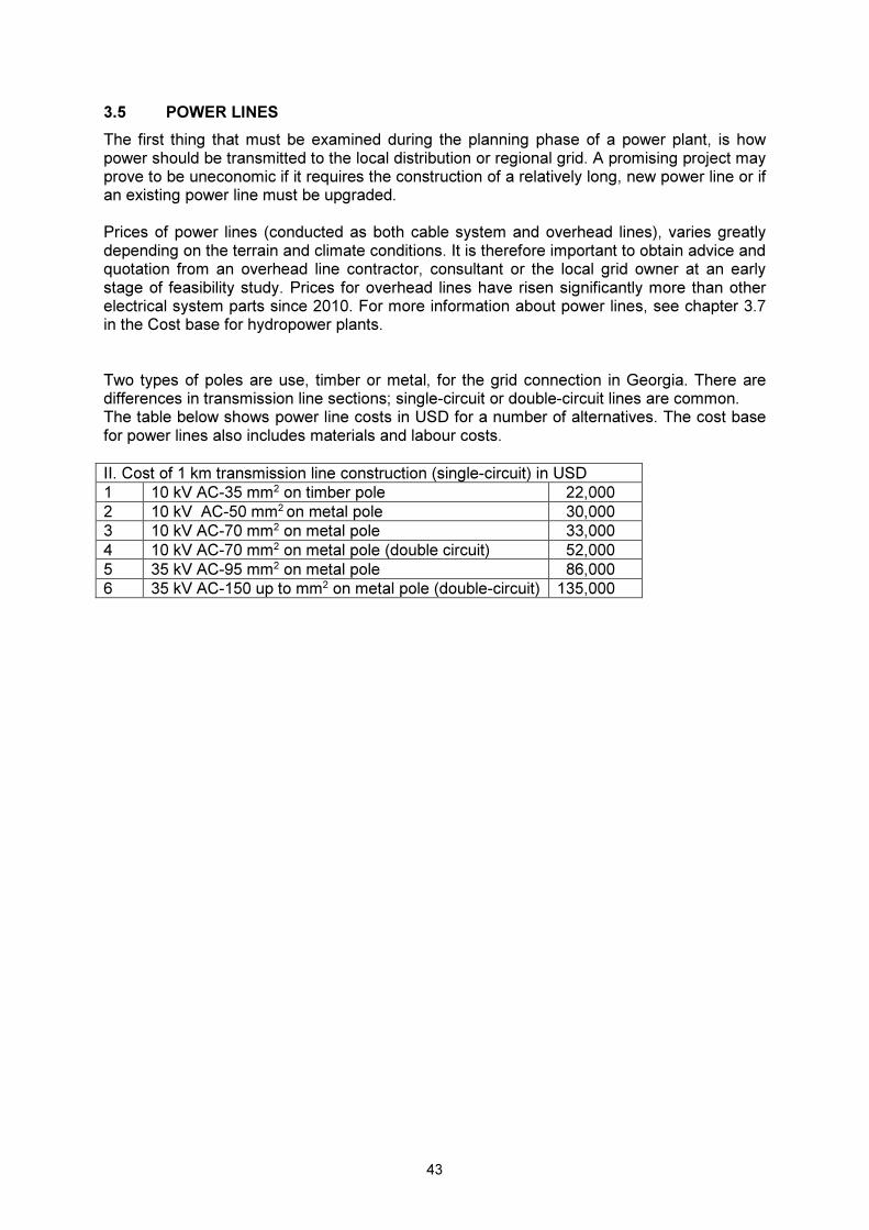
3.5 POWER LINES
The first thing that must be examined during the planning phase of a power plant, is how power should be transmitted to the local distribution or regional grid. A promising project may prove to be uneconomic if it requires the construction of a relatively long, new power line or if an existing power line must be upgraded. Prices of power lines (conducted as both cable system and overhead lines), varies greatly depending on the terrain and climate conditions. It is therefore important to obtain advice and quotation from an overhead line contractor, consultant or the local grid owner at an early stage of feasibility study. Prices for overhead lines have risen significantly more than other electrical system parts since 2010. For more information about power lines, see chapter 3.7 in the Cost base for hydropower plants. Two types of poles are use, timber or metal, for the grid connection in Georgia. There are differences in transmission line sections; single-circuit or double-circuit lines are common. The table below shows power line costs in USD for a number of alternatives. The cost base for power lines also includes materials and labour costs.
II. Cost of 1 km transmission line construction (single-circuit) in USD
1 10 kV AC-35 mm2 on timber pole 22,000
2 10 kV AC-50 mm2 on metal pole 30,000
3 10 kV AC-70 mm2 on metal pole 33,000
4 10 kV AC-70 mm2 on metal pole (double circuit) 52,000
5 35 kV AC-95 mm2 on metal pole 86,000
6 35 kV AC-150 up to mm2 on metal pole (double-circuit) 135,000

44
4 MECHANICAL ENGINEERING
4.1 GENERAL
4.1.1 SCOPE OF DELIVERY
Delivery of mechanical engineering works generally includes equipment fully installed and ready for operation, if not otherwise specified in the comments to each individual price curve. However, the delivery does not include: � Building and construction work � Ventilation, installation of lighting and heating/cooling in the power plant � Spare parts � Value-added tax � Builder expenses � Unforeseen costs 4.1.2 PRICE ESTIMATE
The prices are based on installations purchased in the last five years, and, whenever there is sufficient basis to do so, on installations constructed in the last couple of years. For some components, older prices (index adjusted) are used to obtain a broader basis. The prices have been adjusted for price increase up to 2015 levels. The NOK / USD rate is fixed to 7.5. Since the last cost base update in 2010 there has been significant variations in the cost increase for the different components. Some component groups have experienced price growth exceeding 50%, while others have similar prices now compared to five years ago. In general, turbines have experienced a significant cost increase. Turbine components are manufactured in a number of countries, and are therefore influenced by international price development. It can be pointed out that the price of stainless steel has increased by 15-20% the last five years. Budget prices from suppliers have shown to vary quite significantly. In general, one should be careful using such budget prices in the early phase of projects. Comparison with the price curves in this cost base is recommended. There will be a discontinuity in the price curves when moving from small hydro to large hydro. There are mainly two factors: differences in construction, and local grid requirements. Smaller units can be built relatively simple, typically as compact units, while somewhat larger units needs more robust and expensive constructions. The grid requirements may differ from country to country, imposing different demands on the governors in the plant, and hence price transition from small to large hydro will shift according to the load limits in each country's regulations.

45
4.2 TURBINES
Turbine prices are given as USD/kW nominal effect, and as a function of maximum flow capacity and net head. Price curves have been prepared for each of the most common turbine types on the market for turbines with a power range of between 500–13,000 kW. For turbines with a power range of up to 500 kW, see Chapter 5.3, Micro and mini power units. The rotational speed has been included in the price curves for turbines with a power range of between 500 and 13,000 kW. If the rotational speed is lower than stated in the curves, gears are often used for turbines in the power range below 2–3 MW. The net head graphs indicated in the price diagrams correspond to a common range for small turbines of the Pelton, Francis and Kaplan type, respectively. The highest graphs do not in any way represent an upper limit for the use of turbines of this type. The rotational speed graphs are only indicative, corresponding to a specific forced rate (submersion/suction head). If a turbine is chosen with another rotational speed than the one specified in the relevant flow diagram, the head curve can still be used to define the price per. kW. The rotational speed can be taken into account in the following manner:
If one chooses a turbine with a lower rotational speed than the one shown in the diagram over the given rate of flow and head, the turbine price will generally be somewhat higher than indicated in the diagram based on the value of the rate of flow and the head graph, and vice versa if a higher rotational speed is chosen than the one shown in the diagram. Also, a lower speed will be a safer choice, while a higher speed will be technically more challenging.
The given price level for turbines reflects what can be referred to as a normal price level. There are turbines on the market that are both significantly cheaper and more expensive than indicated in the price curves. We have prepared price curves for the following turbine types: � Pelton � Francis � Kaplan / bulb turbine The following has been included in the individual curves: Turbines with a capacity of 1–500 kW See Chapter 5.3 Micro and mini power units. Turbines with a capacity of 500–13,000 kW The given price curve is valid for turbine, turbine controller and inlet valve (except in Kaplan turbines). For prices of electrical equipment for plants with a capacity above 500 kW, see the price curves in Chapter 3 Electro-technical work.

46
General advice on the choice of turbine supplier In addition to the price, the following should be considered when selecting a turbine supplier: � References. Contact other developers who have used the same supplier. � Power plant automation. Important concerning how much work is required for daily
operations. � The turbine's operating range, the maximum and minimum rate of flow for continuous
operation. Important for making maximum use of the flow. � Efficiency. Be critical of turbine efficiencies that are not supported by reliable
documentation. If available, ask to be shown measurement results from referenced plants, or model test results.
� Operational reliability can be just as important as high efficiency. � Is everything included in the delivery (price)? Check whether the quote includes all
necessary equipment/work. Schematic diagram:
Q
Turbine Generator
Switching station
Transformer
Control installation
Electric meter
Valve

47
4.2.1 PELTON TURBINES
Area of use
For larger installations, Pelton turbines are used for high heads. However, for smaller installations, Pelton turbines may also be used at relatively low heads. The area of use for Pelton turbines overlaps with the area for Francis turbines. Advantages and disadvantages of Pelton versus Francis turbines
Advantages: � The operation range is large, from approximately 10% of maximum rate of flow. Francis
turbines can operate from approximately 40% of the maximum rate of flow.
� Flat efficiency graph, though with a lower best efficiency point than the pointier graph of a Francis turbine.
� No pressure surge problems in the penstock following load rejections, if deflectors are installed.
Disadvantages: � The turbine runner must be located at a certain height above the highest tail water level,
which means some of the head is lost.
� Pelton turbines have traditionally been more expensive than Francis turbines.
The large operating range is often a reason for choosing a Pelton turbine; which makes it possible to handle major water flow variations with just one unit. This is particularly advantageous when there is no large reservoir. Different technical solutions for Pelton turbines.
� Number of nozzles/needles. Using several nozzles gives a larger operation range, whilst at the same time enabling the use of higher rotational speeds and consequently achieving turbines of smaller dimensions. More nozzles are more expensive.
� The most common solution for small Pelton turbines has been an arrangement consisting
of a horizontal shaft and one or two jets. A vertical shaft with several jets is used for larger installations. Most suppliers now offer small vertically arranged Pelton turbines at a price that is often competitive with that of traditional horizontal units.
� Most smaller Pelton units are constructed with the turbine runner mounted directly on the
generator shaft.

48
4.2.2 FRANCIS TURBINES
Area of use
The Francis turbine is the turbine most commonly used in countries with some mountain areas, with an extensive area of use between the Pelton and Kaplan turbines. Advantages and disadvantages of the Francis versus the Kaplan turbine
Advantages.
� A Francis turbine is cheaper than a Kaplan turbine, due to the cost of the runner blade regulating mechanism.
� A Kaplan turbine generally requires greater submersion than a Francis turbine, to avoid cavitation.
� A Francis turbine is suitable for much higher heads than a Kaplan unit. Disadvantages. � The Francis and Kaplan turbines have quite similar best efficiencies, however the Kaplan
turbine has a more even efficiency curve. A Francis turbine has a smaller operation range than a double regulated Kaplan turbine.
For a comparison with the Pelton turbine, see comments on Pelton turbines. Technical solutions for Francis turbines
� Horizontal/vertical rotation axis. A horizontal arrangement is used for most Francis turbines of this power range. This is because construction is simpler and less expensive for horizontal arrangements. Moreover, maintenance access is easier for horizontal arrangements.
� Conventional spiral casings represent the most common solution for small Francis
turbines. Cylinder casing solutions are not very relevant today except for the smallest turbines. A vertical unit with a cylindrical casing turbine may be suitable for very low heads.
� Most small Francis units are constructed with the turbine runner mounted directly on the
generator shaft. Solutions with gears may be economical if the rotational speed is very low.
� To avoid cavitation the turbine runner must be installed in such a way that it has a certain
minimum pressure, either by limiting the suction head, or by submerging the runner below the tail water level. A ”forced” turbine will a have higher rotational speed and smaller dimensions, but will allow for less suction head and require more submersion than a less “forced” turbine. Smaller installations are often constructed with the turbine hall floor and generator above the highest tail water level to avoid the risk of the station flooding. In practice this means that the runner centre must be located two to three metres above the regular tail water level. The rotational speed graphs shown in the price diagram have been prepared for a degree of "forcing" corresponding to this suction head.

49
4.2.3 KAPLAN/BULB TURBINES
Area of use
Whereas large Kaplan turbines can be used for heads of up to 60 m, small Kaplan turbines are rarely used above 25 m. The lower head limit is often determined by the USD/kWh costs. Calculated in USD/kW, Kaplan turbines are relatively expensive. This is because they are used for high flow rates and small heads, resulting in large turbine dimensions in proportion to its installed power. Advantages and disadvantages of the Kaplan turbine.
See the section on Francis turbines. Technical solutions
� Horizontal/vertical rotation axis. Turbines with Kaplan runners come with a number of different arrangements, with both vertical and horizontal rotation axes. Vertical Kaplan turbines have been relatively common. However, one advantage of a horizontal arrangement with axial flow is that the width of the station is reduced, which in general will reduce the cost of construction. The axial flow bulb turbine is quite common for low head run-of-river plant in large rivers. Bulb turbines have a horizontal or tilted arrangement. An S turbine is a variant of the bulb turbine, the main difference being that the generator is located outside the waterway, whereas for bulb turbines it is located in the waterway.
� Double and single regulated Kaplan/Bulb/S turbines.
There are three main ways of regulating these turbines.
1. Double-regulated turbine where it is possible to regulate both runner blades and guide vanes. This is the most expensive solution, but gives an even and wide efficiency curve over a wide operating range.
2. Single-regulated turbine with adjustable runner blades only. This is a less expensive solution with a more pointed efficiency curve. This unit does not have an adjustable guide vane operating system. Start-up, synchronisation and shutdown take place by means of the inlet gate. The solution is quite rare.
3. Single-regulated turbine where only the guide vanes are adjustable and the runner
blades are fixed (also called propeller turbine). This will generally give the cheapest solution. However, the efficiency curve is very pointed.
The low rotational speed of Kaplan turbines may necessitate gear transmission between the turbine and the generator. Another less used alternative for low effects is belt drive transmission. Both gear and belt drive transmissions must be correctly dimensioned to ensure problem-free operation. Even with correct dimensioning, both gear and belt drive transmissions represent wear elements with a shorter lifespan than other main components in a hydroelectric power station. It is quite common that the gear or the gear mechanism needs replacing after ten years of operation. The lifespan of a belt may be even shorter (However, the price will normally be significant lower). Other aspects that should be

50
considered when evaluating the use of gears, are noise and loss of power (approx. 2-3%). Gears are rarely used for turbines with power above 2-3 MW. Comments to the price curves
The price curves apply to double-regulated turbines. A single-regulated turbine will give a lower price. Normally there will only be insignificant variations in the price of mechanical costs of vertical and tilted/horizontal turbines. However, construction costs may vary significantly depending on the choice of turbine arrangement. 4.2.4 OTHER SOLUTIONS AND TURBINES
The turbines and solutions described above are, to the authors knowledge, the most common types of turbines today. There are, however, other turbines and solutions less commonly used. These were more common previously, or they may be common in other countries. Some typical examples are described below. «Double» turbines
A double turbine has two turbine runners connected to the same generator. This solution is rarely used in new units. One solution is to install a complete turbine on each side of the generator. This solution has been used for both Francis and Pelton turbines. Another solution is to have two turbine runners on the same side of the generator. Previously, this solution was often used for small Francis turbines, either with a common intake, a double turbine runner and two separate draft tubes, or with two guide vane operating mechanisms in a common drum or case, and a common draft tube. Pelton turbines were also designed this way. The main advantage of double turbines is primarily that it is possible to increase the rotational speed of the turbine (by a square root of two) compared with a single turbine, without having to increase the forced rate or submersion. The use of gears has resulted in this solution rarely being used today. Cross-flow turbines
The range of use for the cross-flow turbine overlaps that of the Kaplan, Francis and Pelton turbine. In most practical cases, it is used within the same range as the Kaplan and Francis turbines. Cross-flow turbines have been used successfully for small, simple installations in developing countries. The turbine runner resembles a water wheel; the water passes across the wheel transversely and goes through the runner twice, first on its way in to the turbine runner, and again on its way out. Cross-flow turbines are often constructed with a split intake providing a large operating range. Efficiency is, however, lower than for conventional turbines, and it has often proved difficult to sufficiently document its efficiency.

51
The price varies somewhat between different suppliers. Comparisons conducted for specific installations have shown that the cost savings that one would expect compared to a Francis turbine are often insignificant when total costs of the project is considered. Turgo turbines
A Turgo turbine is a partial turbine like the Pelton turbine. It is suitable for medium pressure ranges from 100 to 300 m. It is particularly good if sand erosion is a problem. It has a high specific speed, allowing for higher rotational speed and a more compact turbine than the similar Pelton turbine. Consequently, the generator costs are reduced. Efficiency is approximately 85%.

52
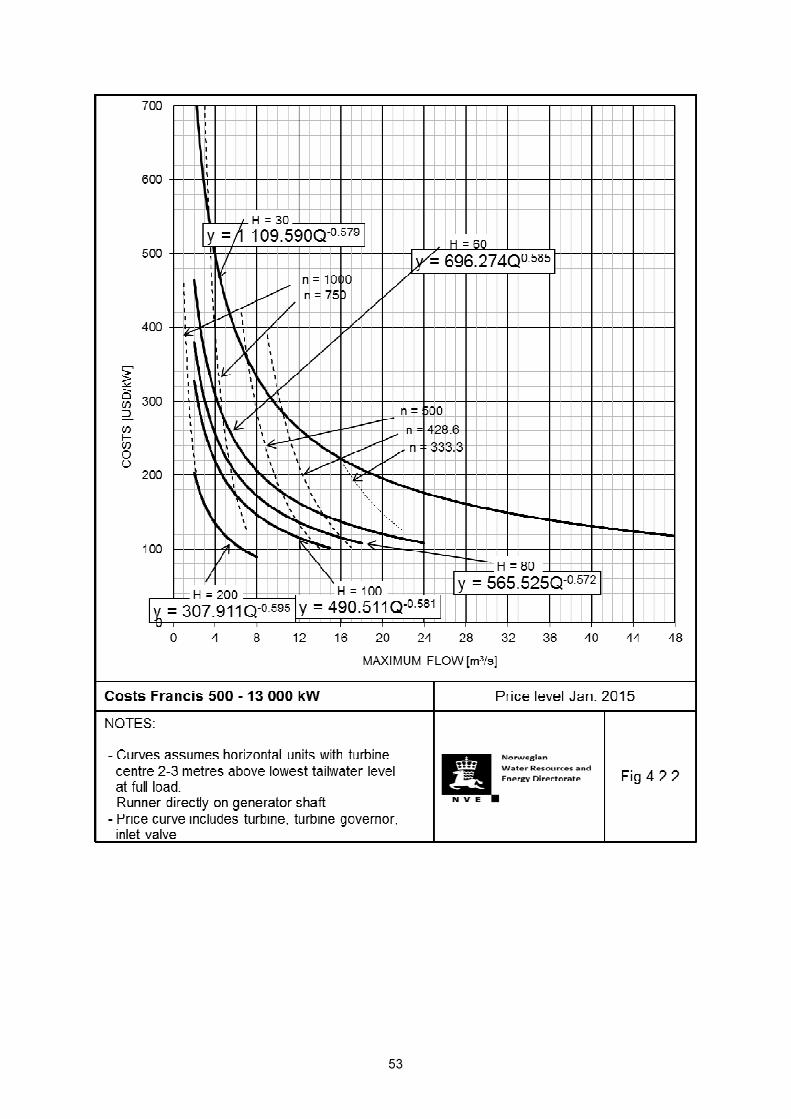
53

54

55
4.3 GATES
The gate prices are given as the function of the gate size. The height of the shaft and gate and the design pressure have been set at a constant value for each price curve and type of gate. Price curves have been prepared for the type of gates that are most relevant for small hydropower plants: � Roller gates � Slide gates � Flap gates � Rubber gates
Dam gates
Dam gates include gates located in the dam. Spillway gates and bottom sluices are often used for large dams. The names of the gates derive from their function or the location of the gate in question. Intake gates
Intake gates comprise gates located at the inlet of a turbine's waterway. 4.3.2 ROLLER GATE
Schematic diagram:
Area of use
Roller gates are most often used as inlet gates. Lifting mechanism
The lifting mechanism consists of a single-acting hydraulic cylinder, i.e. the gate is self-closing. When using a self-closing gate there will only be tensile forces in the pull rod. Gate blade
The gate blade is made from a massive steel plate for small dimensions and low water pressures. For larger dams/water pressures the gate blade is made up of a front panel reinforced with ribs.
Gate blade
Pull rod
Lifting mechanism
Wheel
Pull rod
Water side

56
4.3.3 SLIDING GATE
Schematic diagram
Area of use
Sliding gates are used as discharge gates, spillway gates, draft tube gates, inspection gates and inlet gates. Lifting mechanism
The lifting mechanism often consists of a double-acting hydraulic cylinder or a mechanical winch arrangement. The opening and closing forces are higher on the slide gate than on the roller gate. Gate blade
Operation of the gate blade is the same as for the roller gate. 4.3.4 FLAP GATES
Schematic diagram
Area of use
Flap gates are mainly used in the same way as spillway gates and flush gates. Flap gates are not often used in small dams. Lifting mechanism
Closing takes place by using a single-acting hydraulic cylinder attached either to the top of the gate or a bearing axis. Flap gates are self-opening with water pressure.
Pull rod
Lifting mechanism
Gate blade
Sliding list
Water side
Dam
Gate
Bearing axis
Lifting mechanism
Water side

57
4.3.5 RUBBER GATES
Area of use
Rubber gates are often used to replace dams in smaller plants. In larger plants, parts of the dam may consist of a rubber gate. In a flood situation, air/water will be released from the rubber bladder, and the water will flow over the collapsed gate. Adjustment
Rubber gates are adjusted by either pressurized air or water.

58

59
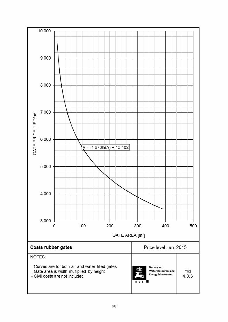
60

61
4.4 INTAKE SCREENS
A synonym for intake screen is thrash rack. The intake screen prices are given in USD as a function of the screen area. Water pressure, the height of the screen and the centre distance between the rack bars have been set at a fixed value. Usage
The intake screen is used to prevent debris, such as logs, twigs and rocks, from entering the turbine waterway and causing damage to valves and turbines. Dimension criteria
The maximum water speed through the intake screen should not exceed approx. 1 m/s, and should be even lower if there is a risk of icing. The screen should be dimensioned for boarding (full blockage) if it is intended to be used during inspection work. Different screen materials
Traditionally, screens have been made of black steel which has been hot dip galvanised and then painted. Alternatively, the screen can be made of stainless steel or a synthetic material such as GRP. Advantages/disadvantages of screens made of stainless steel and synthetic materials Stainless steel: Advantages � Well-tested solution, buckling resistant and non-corrosive, wear resistant, greater
distance between supports (support bars). Disadvantages � High price. Synthetic materials: Advantages � No icing, non-corrosive, price, reduces loss of head provided that the bars are not too
thick. Disadvantages � Not extensively tested on the market, large displacement, short distance between
supports (support bars).

62

63
4.5 LIFTING EQUIPMENT
4.5.1 TRAVELLING CRANE
Travelling cranes cover a large area and are usually used for larger small hydropower plants where there are strict lifting equipment requirements. The cost curves for travelling cranes are in USD as a function of the lifting force. Span, lifting height and lifting capacity are fixed values in the price curve. 4.5.2 ELECTRIC HOIST W/ELECTRIC TRAVELLER
The service area of electric hoists is limited to the area along the crane rails. Electric hoists are available with chains or wires. Chain hoists are suitable for low lifting heights and lifting forces. The length of the crane rails and the lifting height are fixed values in the price curve. 4.5.3 ALTERNATIVE LIFTING EQUIPMENT
For the smallest power stations it may be an option to use a manually operated chain hoist, either fixed or with a traveller. Price curves have not been prepared for such manually operated chain hoists. 4.5.4 MOBILE CRANES
Mobile cranes may be an alternative to permanent lifting equipment at the power plant. If a mobile crane is used there must be sufficient road access and a power station building with, for instance, a removable roof. Price curves have not been prepared for mobile cranes.
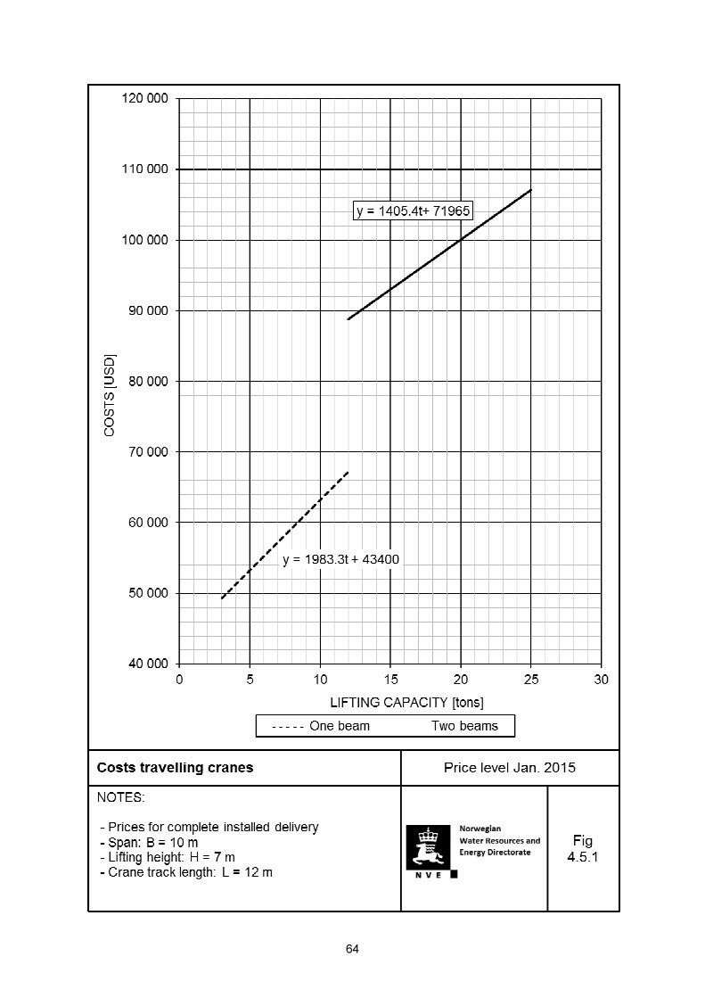
64

65

66
4.6 INTAKE SCREEN RAKES
An intake screen rake is used to clear the screen from debris, and hence reduce head loss. The screen rake can be operated manually or automatically (unattended). Start-up is initiated via a start signal from a time switch or from head loss measurements across the screen. The price of screen rakes varies significantly dependent on supplier, the mode of operation, degree of automation, the screen area and type of debris expected. The price of small screen rakes for a screen area of less than 15 m2 is in the range of USD 20,000-100,000, depending on topics mentioned above.

67
4.7 PIPES
Price curves have been prepared for each of the most relevant pipe types. � PE pipes � GRP pipes � Spirally welded steel pipes � Ductile cast-iron pipes
The price curves indicate the price per metre of pipes. Installation costs have been stated as a percentage of the pipe costs. Installation costs for some pipe types have not been included in the price curves. Where this is the case, installation costs can be estimated as 20-35% of the pipe costs. The price curves are based on penstocks that are minimum 150 metres long. The unit prices will change for shorter or longer penstocks. Unit prices will change with shorter or longer pipes. Installation costs may vary significantly in accordance with terrain conditions and transportation along the penstock route. The prices of the various pipe types may vary considerably between different suppliers. The pressure ratings and dimensions of each pipe type specified in this document are not always permitted for use in all hydropower plants. This depends on the pressure/diameter ratio and the rupture consequence category of the power plant in question. National guidelines (or similar) for dimensioning of pressurized pipes must be consulted in each case, to verify that the chosen pipe is acceptable and within current local safety regulations. It may be profitable to use stainless steel for steel pipes with a diameter of less than 400 mm. This is because maintenance (corrosion protection) is difficult and expensive for small dimensions. Concrete pipes have not been included in this revision of the cost base. This is because these types of pipes are used infrequently in the construction of small hydropower plants. Thus, the price estimate is considered insufficient. The same yields for wooden pipes. However, when refurbishing older plants, for some older wooden pipes it will be beneficial to replace the old pipe with new wooden pipes. This is due to the increased civil costs involved when installing other types of piping. Hence, a table of approximate prices for wooden pipes is included.
68
4.7.1 PE PIPES
Pressure ratings and dimensions
PE pipes are usually held in stock for the following pressure ratings and dimensions:
Pressure rating Available in dimensions [ mm ]
PN 4, PN 6, PN 10, PN 16 from Ø 110 – Ø 630
PN 25 from Ø 110 – Ø 315
on order PN 4 Up to Ø 1,200
SDR-class (Standard Dimension Ratio) is a new parameter used to describe the relation between outer diameter and wall thickness: SDR = [outer diameter ] / [wall thickness] Pressure rating PN is dependent on SDR and the chosen safety margin C. The standard EN 12201-1 is the standard describing this topic. In this cost estimate, inner diameters and pressure rating PN have been used as parameters. Properties
Advantages: � The material is able to withstand rough handling on the site, particularly in cold weather. � The pipes are laid in all-welded pipe sections with 100% protection against permeability � No coating necessary � Long lifespan � Few problems with icing.
Disadvantages: � Low strength and rigidity of the material � Welding results in an inner edge formed at each pipe joint which causes increased loss
of head in the penstock. 4.7.2 GRP PIPES
Glass-fibre reinforced unsaturated polyester Pressure ratings and dimensions
GRP pipes are usually held in stock for the following pressure ratings and dimensions:
Pressure rating Available in dimensions [ mm ]
PN 6 and PN 10 from Ø 300 – Ø 2,000
PN 16 from Ø 300 – Ø 1,600
PN 25 and PN 32 from Ø 300 – Ø 1,400
Properties:
Advantages: � Low weight � Few problems with icing � Suitable for trenching � Little or no maintenance � No extra coating necessary � Low head loss
69
� Chemical resistant � Long lifespan.
Disadvantages: � Require good foundations and anchoring to avoid problems with the pipe joints � Poor impact resistance, can easily be damaged by rocks falling on to the penstock, etc. � Sensitive to quality; production or installation inaccuracies may result in catastrophic
breakdown. 4.7.3 SPIRAL WELDED STEEL PIPES
Pressure ratings and dimensions.
Spirally welded or longitudinally welded steel pipes usually are usually supplied in the dimension range Ø 200 – Ø 1,400 mm, whereas longitudinally welded pipes are used for diameters below 500/600 mm. Pipes produced according to the DIN 2458/1626 standard are pressure tested to 50 bars (500 m water column). When choosing material thickness a rust allowance must be added for each side of the pipe. Properties
Advantages: � Very strong � Require less anchoring than GRP tubes.
Disadvantages: � Require maintenance (coating) � High weight � Welded joints require much work, particularly for large wall thicknesses. 4.7.4 SEAMLESS STEEL PIPES
Seamless steel pipes have not been included in this price review as this type of pipe is rarely used in penstocks for hydropower plants. This is because of its high price, which is approximately five times higher than for spiral welded steel pipes. 4.7.5 DUCTILE CAST-IRON PIPES
Dimensions and pressure ratings
Available in diameters of up to Ø1,800 mm, and for a pressure up to approx. 600 m, standard pipe length 8 metres. Properties
Advantages: � Low installation costs and high corrosion resistance when trenched � Simple and high quality pipe joints.
Disadvantages: � High weight. Previously, K classes were used to categorize ductile iron pipes. This classification is now replaced by C classes. The number behind the C describes the design pressure in bars. 1 bar = 10 mVS.

70
4.7.6 WOODEN PIPES
As mentioned in the introduction, we here indicate prices for wooden pipes for replacement of older wooden pipes. Prices does not include new foundations for the pipes, only minor refurbishment of existing saddles. If new saddles are to be built, one can estimate a cost increase of about 20-30%, dependent on terrain and other factors. Demolition of existing pipe is included.
Price wooden pipes, about 20mWc pressure Diameter Price
[mm] [USD/m]
1,800 1,533
2,200 2,133
2,500 2,533

71

72

73

74

75
5 COMPLETE ELECTROMECHANICAL DELIVERIES
5.1 GENERAL
5.1.1 SCOPE OF DELIVERY
Delivery of complete electromechanical equipment generally comprises all necessary electromechanical equipment at the power plant, installed and ready for operation, if not otherwise specified in the comments to each price curve. A complete electromechanical delivery normally includes the following: � Turbine � Turbine controller � Intake valve � Generator � Control system � Switching station � Transformer 22 kV (see separate note below under micro and mini power units) � All internal cabling at the station � Transport, assuming a passable road � Engineering, installation and commissioning However, the delivery does not include: � Building and construction work � Ventilation, installation of light and heating at the power plant � Spare parts � Value-added tax � Builder expenses � Unforeseen costs 5.2 COMPLETE SMALL HYDROPOWER PLANT UNIT FROM 500–13,000 KW
5.2.1 PRICE ESTIMATE
The price curves are mainly based on regression analysis of tender and contract prices from Norwegian plants. However, these prices levels are considered adequate, as the prices are obtained in an international market. The prices are adjusted to 2015 level. The NOK / USD rate is fixed to 7.5. The price estimate provides an overview of electromechanical installations in power stations, and reflects the price level for a normal scope of delivery and quality of equipment. For small hydropower plants it is important that the electrical equipment is as simple as possible, but still practical and reliable. The price estimate assumes a control system based on the rest current principle, as well as a synchronous generator for generators with a capacity above 1,000 kVA. We further assume that the power plant will deliver electricity to a distribution grid. Budget prices from suppliers have shown to vary quite significantly. In general, one should be careful using such budget prices in the early phase of projects. Comparison with the price curves in this cost base is recommended.

76
There will be a discontinuity in the price curves when moving from small hydro to large hydro. There are mainly two factors: differences in construction, and local grid requirements. Smaller units can be built relatively simple, typically as compact units, while somewhat larger units needs more robust and expensive constructions. The grid requirements may differ from country to country, imposing different demands on the governors in the plant, and hence price transition from small to large hydro will shift according to the load limits in each country's regulations. 5.2.2 SMALL HYDROPOWER PLANT GENERATORS
The prices are given as USD/kW nominal output, and as the function of the maximum flow and maximum efficient head. Price curves have been prepared for each of the most common turbine types on the market with a power range of between 500–10,000 kW. The net head graphs indicated in the price diagrams correspond to a common range for small turbines of the Pelton, Francis and Kaplan type, respectively. The uppermost graphs do not in any way represent an upper limit for the use of turbines of this type. With regards to the choice of turbine type, generator and transformer, etc., please see Chapter 3 ”Electro-technical work” and Chapter 4 ”Mechanical engineering” for more information and detailed explanations for the respective disciplines. 5.3 MICRO AND MINI POWER UNITS UP TO 500 KW
5.3.1 PRICE ESTIMATE
The cost basis is limited for this category. The prices have been adjusted with the same factor as for complete small hydro units, namely 30%. 5.3.2 MICRO AND MINI POWER UNITS
The prices are given as USD/kW nominal output, and as the function of the maximum flow and maximum efficient head. Price curves have been prepared for each of the most common turbine types on the market with a power range of up to 500 kW. For turbines below 10 kW the prices in USD/kW can be very high. The curves for Pelton turbines have been drawn to the lowest outputs as vertical multi-jet Peltons are commonly used for micro turbines. The rotational speed has not been included in the price curves for turbines with a power range of between 1 and 500 kW. Gears are often used for turbines at low rotational speeds, and sometimes belt drive transmission. The net head graphs indicated in the price diagrams correspond to a common range for micro to small turbines of the Pelton, Francis and Kaplan type, respectively. The uppermost graphs do not in any way represent an upper limit for the use of turbines of this type. It should also be mentioned that the given price level for micro units reflects what can be called a normal price level. There are turbines on the market that are both cheaper and more expensive than indicated in the price curves. We have prepared price curves for the following turbine models:

77
� Pelton � Francis � Kaplan/bulb turbine Other relevant turbine types include Crossflow and Turgo turbines. The following has been included in the individual curves: Turbines up to 500 kW
The given price curve is for a complete electromechanical setup, i.e: Turbine, turbine controller, intake valve (not for Kaplan-turbines), generator, control system, switching station, and transformer (if relevant). Transformers are not necessary for installations that are directly connected to the low-voltage grid (240/400V). This usually applies to installations with an output of less than approximately 100 kW.

78
General advice on the choice of micro unit supplier
In addition to the price, the following should be considered when selecting a supplier: � References. Contact other developers who have used the same supplier. � Power plant automation. Important with regards to how much work is required for daily
operations. � Turbine operating range, such as maximum and minimum rate of water flow for
continuous operation. Important for making maximum use of the flow. � Efficiency. Be critical of alleged turbine efficiencies that are not supported by reliable
documentation, preferable 3rd party documentation. � Operational reliability can be just as important as high efficiency. � Does the delivery (price) include everything? Check whether the quote includes all
necessary equipment/work. Schematic diagram:
Q
Turbine Generator Switching
station
Transformer
Control system
Electric meter
Valves

79
5.3.3 PELTON TURBINES
Area of use
Pelton turbines are used for high heads. However, for smaller installations, Pelton turbines may also be used at relatively low heads. The area of use for Pelton turbines overlaps with the area for Francis turbines. Pelton turbines with 1 to 6 nozzles are often used for the lowest rates of flow and outputs. A large operating range is often a reason for choosing a Pelton turbine, as it can handle large water flow variations with only one unit. Small Pelton units do not usually have a traditional distributor ring, and are often installed vertically. The simplest Pelton units may be equipped with a needle valve on one injector and a globe valve in the remaining nozzles/injectors. Mini turbines may have runners made out of composite materials (plastic) if the pressure is below 100 m. 5.3.4 FRANCIS TURBINES
Area of use
The Francis turbine covers an extensive area between the Pelton and Kaplan turbine. Francis units are not usually used for very low outputs, as a multi-nozzle Pelton unit is more practical. A Francis unit may be more suitable than a Pelton unit for low heads, i.e. heads lower than 50 m. However, this depends on the ratio between head and flow rate. 5.3.5 KAPLAN
Area of use
Small Kaplan turbines are rarely used above 25 m. The lower head limit is often determined by the USD/kWh costs. Calculated in USD/kW, Kaplan turbines are relatively expensive. This is because they are used for high rates of flow and small heads, resulting in a turbine of large dimensions in proportion to its output. 5.3.6 OTHER TYPES OF TURBINES
Crossflow and Turgo turbines are described in Chapter 4. These types of turbines are also relevant as micro and mini power units, and are available on the international market down to the lowest outputs. The advantage of a Turgo turbine is that it is more compact than a Pelton turbine. It is also more suitable than a Pelton turbine if there is a risk of sediment erosion. The advantage of a Crossflow turbine is that it is relatively easy to maintain and inexpensive to purchase.

80

81

82

83

84

85


![Workshop Hydropower and Fish.pptx [Schreibgeschützt] - Workshop Hydropower and Fish... · Workshop Hydropower and Fish Existing hydropower facilities: ... spawning grounds and shelter](https://static.fdocuments.in/doc/165x107/5a8733247f8b9afc5d8da3c5/workshop-hydropower-and-fishpptx-schreibgeschtzt-workshop-hydropower-and-fishworkshop.jpg)