GEOPH RPT ON 23 MINING CL · claims held by Score Resources Ltd., 15 miles east of Hemlo Seventeen...
38
42C12NE8147 42Cl2NEe017 WHITE LAKE (SOUTH) 010 GEOPHYSICAL REPORT ON 2 3 M INING CLAIMS WHITE LAKE AREA (SOUTH PART) SAULT STE. MARIE MINING DIVISION, ONTARIO for Score Resources Limited Vancouver, B.C. RECEIVED JUN 31983 MINING UNDS SECTION O.G. Harder T.R. Foster Manwa Exploration Services Ltd Vancouver, B.C. May 6 1983
Transcript of GEOPH RPT ON 23 MINING CL · claims held by Score Resources Ltd., 15 miles east of Hemlo Seventeen...

42C12NE8147 42Cl2NEe017 WHITE LAKE (SOUTH) 010
GEOPHYSICAL REPORT ON 2 3 M INING CLAIMSWHITE LAKE AREA (SOUTH PART)
SAULT STE. MARIE MINING DIVISION, ONTARIO
for
Score Resources Limited Vancouver, B.C.
RECEIVEDJUN 31983
MINING UNDS SECTION
O.G. Harder T.R. Foster
Manwa Exploration Services LtdVancouver, B.C.
May 6 1983

SUMMARY
A magnetometer and VLF EM survey were conducted on 23 claims held by Score Resources Ltd., 15 miles east of Hemlo
Seventeen conductors were identified. The most inter esting area, at present, is the northeast corner. Here a coincident bedrock conductor and magnetic anomaly follows the regional geological trend, near the volcanic-sedimentary contact.
Further work is recommended including additional EM, magnetometer, geologic mapping, prospecting, soil geo chemistry stripping and trenching. Diamond drilling would be contingent on the results of above.
D. Glenn Hardec, B.A. B.Se. I.R. Foster, B.Se. May 5, 1983

42C12NE*M7 42C12ME8ei7 WHITE LAKE (SOUTH) 01OC
TABLE OF CONTENTS
SUMMARY
INTRODUCTION
LOCATION AND ACCESS
LEGAL STATUS
REGIONAL GEOLOGY
RESULTS OF VLF EM SURVEY
RESULTS OF MAGNETOMETER SURVEY
DISCUSSION
RECOMMENDATIONS
CERTIFICATE
APPENDIX I
APPENDIX II
APPENDIX III
APPENDIX IV
Map l
M'ap 2
INSTRUMENT SPECIFICATIONS
SURVEY PROCEDURE SABRE VLF EM RECEIVER
MAGNETOMETER SURVEY PROCEDURE
DETAILED DESCRIPTION OF CONDUCTORS ON SCORE PROPERTY
Magnetometer Survey of Score Claims
VLF EM Survey of Score Claims
l
l
1
2
2
3
3
4
5
6
7
8

- l -
INTRODUCTION
Magnetometer and VLF EM Surveys were conducted by Manwa Exploration Services Ltd on the 23 Score claims in the White Lake area. The work was done between April 10 and April 20. The line spacing was 400 feet and the station interval was 100 feet. A total of 19 miles was surveyed with the two methods. An average of 2 feet of snow covered the ground.
The Sabre VLF EM receiver was operated by T.R. Foster of Sault Ste. Marie. The Scintrex MP-2 proton magnetometer was operated by D.G. Harder of Deep River Ontario.
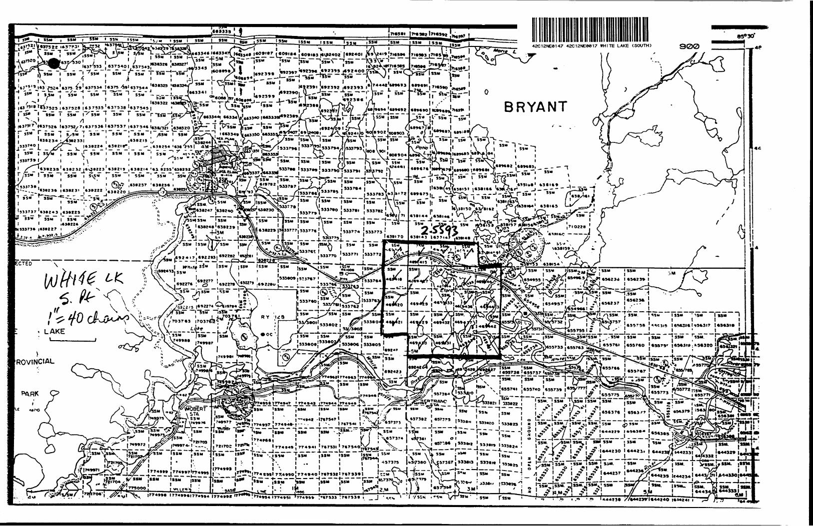
LOCATION AND ACCESS
The subject claims are located along Highway 17, 15 miles east of the Hamlo gold discoveries. The town of White River lies 15 miles to the southeast. The road to the Mobert Indian Reserve passes through the northwest portion.
About 25X of the property is underlain by water. The main body of water is Elora Lake through which the White River passes.
LEGAL STATUS
The 23 contiguous unpatented mining claims (920 acres) are located in the White Lake {South Part) Area, Sault Ste Marie Mining Division. The claims straddle the boundary of McCron and Bryant Townships and an unsurveyed area to the west.
The present owner is Score Resources Ltd., and the claims are numbered SSM469415 to 469420 inclusive, SSM469427 to 469438 inclusive, SSM 469441 to 469444 inclusive.

- 2 -
REGIONAL GEOLOGY
The claims are mainly underlain by Precambrian meta sediment and lesser metavolcanics in the northeast corner. The general trend is northwest, with the contact northeast of Elora Lake. Two short diabase dykes, roughly north- south, cross the highway. (Source: ODM Map P. 494, Manitou wadge Sheet, Scale 1":2 miles).
RESULTS OF VLF EM SURVEY
Seventeen anomalous zones, or conductors, have been outlined by crossovers, inflections and broad flat sections in the V.L.F-E.M. profiles. They have been designated by the letters A through Q. A detailed description of each conductor is presented in Appendix IV.
Anomaly B appears to be a legitimate bedrock conductor. It strikes 140 0 and dips steeply northeast. It appears to be a single sheet structure with a surface trace at least 900 feet long.
Anomalies A and J may be steeply dipping bedrock con ductors which are masked by highly resistive overburden. It is more likely that they are caused by conductive over burden.
Anomalies L and M are similar in characteristics to A and O but may be steeply dipping bedrock conductors of moderate conductivity covered by resistive overburde'n.
Anomalies N, P and Q are interpreted to be conductive overburden but local topographic features indicate that they may be faults or shear zones filled with conductive materials.

- 3 -
Anomalies C, D, E, F, G, I, K and O are Interpreted to be caused by conductive overburden or lake bottom sediments and clays* Anomaly H 1s probably caused by a small creek and associated conductive overburden.
RESULTS OF MAGNETOMETER SURVEY
Readings of the total magnetic field were plotted with respect to a base level of 59,000 gammas. Readings ranged from 114 (59114) to 1818 (60818) gammas. The majority of readings were in the 600-800 range. The major contour interval chosen was 300 gammas with a secondary interval of 150 gammas from 600 to 750 and 750 to 800 gammas. A weak regional trend of about 330 0 is apparent.
A fairly strong north-south anomaly, at least 1400 feet long, occurs west of the base line between 8N and 16S. The source is steeply dipping and quite narrow. A secondary anomaly occurs, 200 feet to the west, striking 345 0 , apparently dipping steeply east.
In the northeast a series of 3 or 4 narrow moderate magnetic anomalies strike around 010. Another anomaly, striking 030, parallels conductor B from 20N, 19E to 8N, 22E.
DISCUSSION
i
Most of the stronger magnetic anomalies do not coincide with conductors, suggesting diabase dykes. The exceptions are conductors A and B which have a fairly strong parallel magnetic expression. Conductors N and O have a weak magnetic expression.

- 4 -
The most Interesting area 1s the northeast corner, particularly conductor B which follows the regional strike of about 320. This conductor 1s near the sedimentary- volcanic contact, a similar environment to that of the Hemlo 'orebodies.
As the geology 1s similar to Hemlo, follow-up ground surveys are definitely warranted.
RECOMMENDATIONS
1. Detailed f11l-1n with VLF EM and magnetometer 1n the , northeast corner (200 feet spacing).2. Testing of selected conductors with a more discrimina
ting EM system or possibly IP or SP.3. Detailed geologic mapping and prospecting over the
entire property.4. Soil geochemical survey, concentrating at conductors.5. Stripping and trenching of anomalies.6. Diamond drilling contingent on results of above.
m\v^

- 5 -
CERTIFICATE
I, DONALD GLENN HARDER, of 51 Hlllcrest Avenue, Deep River, Ontario do hereby declare that
l I.I have worked as an exploration geologist on a fulltime basis since 1975; prior to 1975 as a geological assistant for four field seasons and one winter.
2. I graduated from Queen's University with a General BA In 1969 and frn-i the University of Ottawa with a B.Se. (Hon) in 1976.
3. This report is based on on-site supervision of the geophysical surveys.
4. I have no interest nor expect to receive any interest in the subject claims.
5. I have been a contract geologist and consultant since 1976.
D. Glenn Harder, B.A., B.Se. May 6 , 1 983

- 6 -
APPENDIX I
INSTRUMENT SPECIFICATIONS
SABRE VLF-EM RECEIVER
Transmitting Stations
Parameters Measured:
Dimensions: Power Source:
Seattle Washington (24.8 kHz)Cutler Main (17.8 kHz)Annapolis Maryland (21.4 kHz)
Dip Angle of null of field
total field strength
out of phase component of fieldstrength
8.5" x 9.5" x 2.5"8 size AA periite(alkyline)batteries
SCINTREX MP-2 PORTABLE PRECESSION MAGNETOMETER
Resolution:Total Field Accuracy;
Range: Display:
Power Source: Size:
Total Weight:
l (one) gamma± l (one) gamma overfulloperating range20,000 to 100,000 gammas5 digit L.E.D. readout of totalmag. field in gammas8 size D alkyline batteriesconsole with batteries 80xl60x250mmSensor 80x150 mmStaff (extended) 30x1550 mm3.7 kg.

- 7 -
APPENDIX II
SURVEY PROCEDURE - SABRE VLF EM RECEIVER
The survey was conducted on a picket grid with cross- lines established at 400 foot intervals. Stations were spaced TOO feet apart on the crosslines. Readings were occasionally taken at 50 foot intervals in anomalous areas.
Data obtained included total field strength and the out of phase component of same and the dip angle of the null of the field. It was obtained through a two-step procedure.
(1) The receiver was held in a horizontal position and the operator rotated u-lil the Field Strength Meter read a minimum, thus aligning the receiver coil axis parallel to the direction of the primary field.
(2) The receiver was raised into an upright (vertical)position and rotated about a horizontal axis until the Field Strength Meter again read a minimum; the dip angle of this null position was recorded from the Inclinometer.
Total field strength readings were taken with the receiver in the vertical position (step 2) and the inclinometer reading zero. The out of phase component of the total field is represented by the remnant field strength value at the null of field position.
Data presented is unfiltered. Field strength values are corrected to an arbitrarily chosen "base gain" setting or value.

- 8 -
APPENDIX III
MAGNETOMETER SURVEY PROCEDURE
The Scintrex MP-2 sensor was mounted on a staff, 7 feet above the ground and always oriented north-south.
A permanent and moving bay station system was used. Readings were corrected for diurnal drift. Values are plotted with respect to 59,000 gammas.
fe'

- 9 -
APPENDIX IV
DETAILED DESCRIPTION OF CONDUCTORS ON SCORE PROPERTY
Numerous anomalous areas have been discovered on the claim group. Crossovers, inflections and flat profiles
i with many successive zero degree dip angle values indicate a 1 variety of types of conductive horizons. Conductors have
been assigned letters and will be discussed in alphabeticalorder, not in order of attractiveness.
conductor A: transmitter used - Annapolis (21.4 kHz)
one line (short strike length) in topographically high but flat and possibly swampy ground symmetrical shape with moderately high magnitude of dip angle and field strength bordered by false crossovers on east and west.
interpretation: possible steeply dipping, narrow sheet but false crossovers indicate either multiple conductors or more likely conductive overburden.
conductor B: transmitter used - Annapolis (21.4 kHz)
3 (possibly 5) line in topographically high area on side of moderate to steep west slope; strike length of at least 900 feet on azimuth of 140 0 . as'symetric profiles with higher dip angle values on east side indicating moderate to steep northeast di p.false crossovers on west flank of conductor probably caused by poi/er line influence.

- 10 -
i nterpretation: legitimate bedrock conductor; moderate to seeply northeast dipping sheet of narrow width.
conductor C: transmitter used - Annapolis (21.4 kHz)
two line in topo. low and swampy valley.low magnitude of dip angles and flat broad profileassociated with low field strength.
i nterpretation: conductive overburden; flat lying sheet
conductor D; transmitters used - Annapolis (21.4 kHz)
- Cutler (17.8 kHz)
long sinuous conductor occurring over Elora Lake andfollowing outline of shore.high updip field strength and low downdip fieldstrengthlow downdip tilt angles thus broad profiles.
interpretation: clay edge/conductive lake bottom sediments.
conductor E: transmitter used - Annapolis (21.4 kHz)
low line sinuous conductor occurring over Elora Lake and following shore linerelatively higher updip field strength and tilt angles causing broad profiles.
interpretation: clay edge/conductive overburden.
conductor F: transmitter used - Annapolis (21.4 kHz)
on line over oxbow lake on line 12 South a.t 23+25eastvery high positive tilt angles likely caused by
power line influence; low negative tilt angles and
flanking false crossover; moderate to very high
associated field strength.

- 11 -
Interpretation: flat lying sheet/conductive overburden or lake bottom sediments.
conductor G: transmitter used - Cutler {17.8 kHz)
long sinuous conductor occurring over Elora Lake and essentially following probable water-flow direction. flat, broad profiles with low associated field strength.
interpretation: clay edge/conductive lake bottom sediments.
conductor H: transmitter used - Cutler (17.8 kHz)
in broad valley at base of gentle to moderate east-slope beside small creek on line 32 south at 11 westtwo associated inflections on line 28 south at 11 west and line 36 south at 11 west
- assymetrlc profile with relative high positive tilt angles in a topographically lower area; moderate associated field strength
1 nterpretation: creek and associated conductive overburden
conductor I: transmitter used - Cutler (17.8 kHz)
crossovers on line 32 south at 16+50 west and on4
line 36 south at 15+50 west, both on gently slopingground.broad profiles with associated moderate fieldstrength and low dip angle valves.
1 nterpretation: conductive overburden associated with local drainage system.

. 12. ;,*
conductor J: transmitters used - Cutler (17.8 kHz) i- Annapolis (21.4 kHz) - j
E.
t
- three line conductor of approximately 1,000 foot strike length located over a pond and swampy area near the base of a moderate east-slope, azimuth of conductor 155 0fairly sharp, assymetric profile with higher positive tilt angles over pond and higher negative tilt angles in swampy area
- moderate to high associated field strength
interpretation: shallow to moderately northeast dipping sheet; possibly a bedrock conductor masked by conductive overburden or just conductive overburden.
conductor K: transmitter used - Cutler (17.8 kHz)
- located at baseline 16 south on hammocky ground with general gentle northeast slope toward Elora Lake.
- broad profile, low tilt angle, moderate fieldstrength and associated false crossover at Baseline14.
interpretation; nearly flat lying sheet of low conductivity probably conductive overburden
conductor L: transmitter used - Annapolis (21.4 kHz)
three line conductor of approximately 1,000 footstrike length located 400 feet west of baseline from8 south to 16 south in an area of gently rollingtopography.azimuth of conductor approximately 155 0nearly symmetrical profiles on lines 8 and 16 south,with anomalously high tilt angle on line 12 south at2 west distorting that profile.

- 13 -
- higher field strength associated with positive tilt angles.
interpretation; possible bedrock conductor masked by overburden; northeast dipping sheet of low conductivity
conductor M: transmitter used - Annapolis (21.4 kHz)
two line conductor of approximately 600 foot strike length located on flat to gently rolling topography, near-symmetric, moderately wide profiles with associated low to moderate field strength and tilt angle values.azimuth approximately 135 0 and north east dip indicated by slightly higher positive tilt angle values.
i nterpretation: possible bedrock conductor masked by overburden of low conductivity.
conductor N: transmitter used - Cutler Maine (17.8 kHz)
two (possibly 3) line conductor of approximately 600foot strike length located on generally flat ground;a topographic depression with margins at 15+40 westand 14+60 west on line 00 indicates a possible faultor shear zone is associated with the crossover at 14west.azimuth of conductor approximately 143 0profiles are broad and nearly symmetrical withassociated low tilt angles and field strengthvalues.an inflection in the profile on line 4 south at 13west infers that the strike length may be as greatas l,000 feet.

- 14 -
Interpretation: probable conductive overburden or steeply dipolng shear zc.ie masked by overburden.
conductor 0; transmitter used - Annapolis (21.4 kHz)
one line conductor located on line 8 north at 19 west in area of flat to gently rolling topography, broad, flat profile with low associated field strength.
i nterpretation: horizontal sheet; conductive overburden
conductors P and Q: transmitter used - Annapolis (21.4 kHz)
crossovers on line line 4 south at 25+75 west and line 12 south at 27+50 west; possibly the same structure (crossover on line 4 south is of moderate with and associated with high positive tilt angles and high field strength values.crossover on line 12 south is of narrow width and associated with low tilt angles and field strength, both crossovers are flanked by false crossovers crossover on line 4 south in flat swampy area and crossover on line 12 south occurs in narrow valley bordered by moderately sloping hills.
i nterpretation: possible shear zone but likely conductive overburden.
o
*t
Si!
.'..I..
"l——
-,.
fi^icft
-,."
\
*.l.L
5sa
— i—
i. u
.
i z
IsryJIrT3—
H,'jSi.
*f-H
T1
s
S 'ii
ilU
-Lv
.--^ - -
iii.D/M
/.I S
V
W
l "
W
j*
k mII '
l
tfeij IB
11,—i—io
l o
.: l
i8# ^ a * i
S A i/
^f
15 in i :1
S l
l*-T-7T---M
f-j-fir——
'-i
i!\ir|ij li i l/J rftRii jt-! in [i
2 7 5 l* r1
Si IM
Jtd
l: el"?
5l
'"•!s
ISc
sN
'
VI
'f'
S
l
-*-ja^:x
?iil?
!
Ull
ilf
J lg
--"If
V4
l:
- LIL^iiX
llVsliX
inX
ff
s i!i
' sis 5 IR ; IK 3 r
'vi'STivsisT
~1r-.- :T?.—""*r*" ""*r^ii
!vii^l-t^
jj^^
fjl**__-J
M?
__'i
——
——
, O
.l-
VI
r^'I
l **
P-*'AJL^K
| o" L^j?.:v\i*ii
V
l:^
p_
a
l Aijr....i*j! is
ViS
'^1
8%
N
18O
Nn
OK
ON
lrfOo* ,
*-l?
--*-i--
--- ----.
- -.• l
i!r1: -r-;
11* r
'a
ZT
jfT.p—
*lV'~
—i
*/*
-S f "S
5"(^i. A
ll
r-r-^i s. ^
^. C--Z4 -
. ri
r,N
;-
li? 1)
-i o;
ni .
?l
S' R
f S
SIS
e
'* 21218
itl-Hi
a sil
R , g
' t
S i *
S ' aSfiLjLjS?' ^.rjA
ljf.U
vi V
llVi
m
i vi
"
i vi n
l — —
——
L.- —
-*— —
—i —
-~ —
S 5**
*1(l '
Vi (l
l it
A- —
-f-
— -
— \-
. ——
^.
11
5 IS 8,
• l
I
!i S^'-fj
\~rrr
h
5 !i
(S, s
i!i^-r^
"iif- Us s/ij
!j!—
-4--t-^——
—-t —
n
. .
r s
Si
IS 1(
^4
"1
*1 "
' "
"
'M
\ *i'v
*L
J
"
l*1 '
IsL-c
'"
\— — — — x. JL — JP .
"ti
•!
V^-8-
i i
*' i'
5'.El.'..y..j!U:;*l
r-1 *
T/
;^s |!|l.-';3
Kto-.P
I *c
a
v
r j
Q *-
v in M
o
v
* g
r-2H
--w-^-!---8J
. i*
la *
."M
V
I '*
l.
k * W
T
ir-^Jt,
'VWM
K!*-:-
--
-v 1
'*2
1 \*
' J
blS
J5ii;
S l* g
12 18
2 iSa
r
:i* ^
"5 5n
fs'iiiuj d a 2 ' 3
ali"
'mpvij i "
P ' "w ...|2-^r^-r-77t*---W
Z. *
~—
l
,' *
j
iiii.i.X'5
s \'
.* l
1*"1^1;
i* V
*:*:S. l.
n
vi
r--, ---r--t---r~--.~
- ~^1 - ~:.nn
ftb"i!*
Si-* l
l11"
vr — r*-.-*1"
'^r^.'. —
^* i m
M
l —
-.-?;. .-^
.^ s
1vi
n l-*
- -I--- I l
'f "J
Ml,
Vxi
V^v^ TS
^^ o
-^" - "^t-"
xc \r* v\ wx ^
*ii-S
.
'A..
~.s?
^
n
' i.1
*" i
cr
" J

Ontario
Ministry of Natural Resources
GEOPHYSICAL - GEOLOGICAL - GEOCHEMICAL TECHNICAL DATA STATEMENT
File.
TO BE ATTACHED AS AN APPENDIX TO TECHNICAL REPORTFACTS SHOWN HERE NEED NOT BE REPEATED IN REPORT
TECHNICAL REPORT MUST CONTAIN INTERPRETATION, CONCLUSIONS ETC.
Type of Survey(s)
Township or Area Claim Hnlrier(s)
t***MINING CLAIMS TRAVERSED
List numerically
C; ^ ^ • /JA
Survey r^mnart
Author of ReportAddress of Author
Covering Dates of Si.rvry /0(Unecutting to office)
Total Miles of Line Hut .3*? '/ft g
SPECIAL PROVISIONS CREDITS REQUESTED
ENTER 40 days (includes line cutting) for first survey.ENTER 20 days for each additional survey using same grid.
Geophysical—Electromagnetic.—Magnetometer-——Radiometric——.
—Other———.—..
DAYS per claim
Geological.
Geochemical.
(prefi*) (number)
AIRBORNE CREDITS (SpecUI provWon trediu do not .pply to airborne Mirveyi)
Magnetometer .Electromagnetic. Radiomct ic(enter diyi per diim)
SIGNATURE:.Author of Report or A|cnt
Res. Geol.. .Qualifications.
Previous Surveys File No. Type Date
....^ RECEIVED
Claim Holder
l
JUN o 19&
....................... MINING LANDS Z
H
:cC/ 6 Q V It'2." V ' TT f *-f).6.H...,,,,..., .....,.......
*7 V f Y Y *s
W 'W/
"7 "iMp^^nn * * f^W A 1 kf C ^*C .^7TOTAL CLAIMS ——— ^ ^ — —— — .

GEOPHYSICAL TECHNICAL DATA
Number of Station i Station interval Profile scale ___Contour interval.
- If more than one survey, specify tla(a for each type of survey
/X
3O
.Number of Readings
.Line spacing
InstrumentArnirary — Srali- constant —
Diurnal eorrertion method , , sriAy
Base Station check-in interval (hours)Rase Station location and value ,, ,,, , fat
1 /"xu \' ( Oh*') ^A**,t*\tLf'** 6* 1C- -S-ftV/,*^ /06AI
'/-•z rJ * ^H? A j ^^^9 "7 T"^^d'5*' L.tftC' i 0 rV . , J f f^f? C.#st*lt*\Cl,9
r
Instrument,Coil configuration Coil separation -— Accuracy ————— Method: Frequency——
Parameters measured.
Fixed transmitter O Shoot back Q In line D Parallel line
(iptdfy V.LF.it.tion)
Instrument.Scale constant,Corrections made.
Base station value and location.
Elevation accuracy.
InstrumentMethod D Time Domain Parameters — On time ———
- Off time ^—— Delay time ——- Integration time.
Power.
.r'
D Frequency Domain _ Frequency_____ Range ^.^.....^p..
Electrode array— Electrode (pacing. Type of electrode,

Ontario
s. \ ,Ministryof Report of WorkResources (Geophysical, Geological,
Geochemical and Expenditures)
The Mining Act
Instruction*: - f .ease type or prinf '— K number of mining claims traversed
exceeds space on this form, attach a list. Note: - Only days credits calculated in the
"Expenditures" section may be entered in the "Expend. Days Cr." columns.
— Do not use shaded areas below.
Name and Addreii of Author (of Geo-Technlcal report)
P- (y.Credits Requested per Each Claim in Columns at rightSpecial Provisions
For first survey:Enter 40 days. (This includes line cutting)
For each additional survey: using the same grid:
Enter 20 days (for each)
Men D* y*
Complete reverse side and enter total(s) here
.Airborne Credit!
Note: Srecial provisions credits do not apply to Airborne Surveys.
Geophysical
- Electromagnetic
- Megneiometer
' Radiometric
- Other
Geological
Geochemical
Geophyiical
- Electromagnetic
. Magnetometer
- Radiometric
- Other
Geological
Geochemical
Electromagnetic
Magnetometer
Radiometric
Oayi perClaim
wz0
Dayi per Claim
— ————
Days perCHim
——————
Mining Claims Traverted {List in numerical sequence)
Expenditures (excludes power stripping)Type of Work Performed
Performed on Oelm(t)
Calculation of Expenditure Oeyt Credit!
Totel ExpendituresTom
Diys Credits
15Instructions
Tout D* y f Credits mty be apportioned et the claim holder's choice. Enter number of days credit! per claim selected In columns et right.
ryy Totel number ol mining
cliims covered by this report of work.
Recorded Holder or AgenUSignature)
Total Day* l Recorded
Fo^Qf ficeUse Only"te Recorded
til Approved eyRecorded.,
ification Verifying Report of Work
Mining Recorder
Branch Director
l hereby certify that l have a personal and intimate knowledge of the facti tat forth in the Report of Work annexed hereto, having performed tne work or witnessed same during and/or af tar lu completion and the annexed report li true.
Name and Poital Address of Person Certifying
Date Certified Certified by (Signature)
1302(81/9)

l l
Assessment Work Breakdown
edbyWMan Days are based on eight (8) hour Technical or Line-cutting days. Technical days include work performed consultants, draftsmen, etc..
03VI3D3JI
O!'i"'3^ i OU A i O.'IUIM

Ministry ofNaturalResources
Technical Assessment Work Credits
OntarioOil*
February 16,1984
F "^.5593
Mining Rtcordtr'l R*pori ol Work No.
Recorded HolderScore Resources Ltd.
Township or AreaWhite Lake Area (South Part)
Type ot survey end number ol Assessment days credit per claim Mining C leimf Anetied
Geophysical tElectromagnetic. 40
Magnetometer.
Radiometric...
Induced polarization.
Other ——..——
.deyi
. deyi
. dtyt
.deyi
.deyi
SSM 469415469417 - 18 469420 to 21 1nd. 469427 to 37 1nd.
Section 77 (19) 8** "Mining Clilnw AiiWMd" column
Geological —————————————————— diyi
Geochemical .__________________ deyi
Man days D
Special provision (Z)
Airborne D
Ground El
0 Credits have been reduced because of partial coverage of claims.
D Credits heve been reduced because of corrections to work dates and figures of applicant.
Special credits under section 77 ( 16) for the following mining claims
30 days credited
469416469438469442469444
20 days credited
469419
10 days credited
469441
No credits have been allowed for the following mining claims
not sufficiently covered by the wrvey
469443
D Insufficient technicel dete filed
The Mining Recorder may reduce the above credits If necessary In order that the total number of approved assessment days recorded on each claim does not exceed the maximum allowed as follows: Geophysical — 60; Geological — 40; Geochemical — 40; Section 77091—60:820 (83/6)

Ministry o! Natural
SourcesOntario
Technical Assessment Work Credits Dut
February 16, 1984
File2.5593
Mining Rteordtr'i RtpOM Of Work No
Recorded Holder
Township or AreaScore Resources Ltd.
White Lake Area
Type ol survey end number ol Assessment days credit per claim Mining Clilmt Ai**M*d
Geophysical
El*ctrom*gnttic.
M*gnttom*ttr.
FUdiomttric —
20
Induced poltnution.
Othtr ————————
. diyi
. d*yt
.d* yi
SSM 469415 469417-18 469420 to 21 1ncl. 469427 to 37 1ncl.
Section 77 (10) S** "Mining CJtln* AitMMd" column
Geological __________________ day*
Geochemical __________________ d*yi
Man days D
Special provision S
Airborne D
Ground GD
H Credits have been reduced because of partial coverage of claims.
Q Credits have been reduced because of corrections to work dates and figures of applicant
Special credit! uitder section 77 ( 16) for the following mining claims
15 days credited469416469438469442469444
10 days credited 469419
S days credited 469441
No credit! have been allowed for the following mining claims
not sufficiently covtrtd by th* turvty
469443Q Insufficient technics! dst* f ilsd
The Mining Recorder may reduce the above credits if necessary In order that the total number of approved assessment days recorded on each claim does not exceed the maximum allowed as lollows: Geophysical — 60; Geological — 40; Geochemical —40; S*etion77lig)—60:82B (63/6)

2.55931983 06 08
Mrs, H .V. St. .talesMining Recorder8/5 QtiQftn Street lastP.O. Box 669SAULT STE. MARIE. OntarioP6A 6N2
Dear Madarat
We have received reports and naps for n Geophysical (Electro- nngnetic and Hngnatonoter) survey submitted under Spnclal Provision* (credit for Performance and Covorage) on mining claims SSM 459415 et al 1n tho Area of White Lake (South Tart).
This material will be examined and assessed and a statement of a&muiont wark credits will ho Issued.Yours very truly,
E. F. AndersonDirectorLand Management Branch
Whitney Block, Room 6450 - i |Quften 1 * Park ' |Toronto, Ontario tMM 1H3 iPhonet 416/965-1380 '' iA.Barnelb lcct Score Resources Ltd.
922-510 West Hastings Street Vancouver, B.C.
v; V6B 1L8t: D. Slenn Harder
Box 1360Deep River, Ontario KOJ iro

t
September 23, 1983 2.5593
Score Resources LtdSuite 922510 West Hastings StreetVancouver* B.C.V6B 1L8
Dear Sir:
RE: Geophysical (Electromagnetic and Magnetometer) Surveyon mlnlgg claims SSH 469515 et al In the Area of White Lake
Returned herein art the magnetometer and electromagnetic plans (1n duplicate) for the above-mentioned survey.
Please have the author of the report sign each copy of the maps and return them to this office quoting file 2.5593.
For further Information, please contact Mr. F.W. Matthews at (416)965-1380.
Your* very truly,
E.F. AndersonDirectorLand Hanagement Branch
Whitney Block, Room 6450 Queen's Park Toronto, Ontario M7A 1W3 Phone:(416)965-1380
S. Hurst:me
End.
cc: Mining RicevdtrSault Ste. Marie, Ontario
January 27, 1984
REGISTERED
Score Resources HaltedSuite 922S10 Vest Hastings StreetVancouver, B.C.V6B 1U
Our File: 2.5593
Dear Sir: RE: Geophysical (Electromagnetic t Magnetometer) Survey
submitted on Mining Claims SSM 469515 at al 1n the area of White Lake.
Enclosed 1s a copy of our letter dated September 23, 1983, requesting additional Information for the above mentioned survey.Unless you can provide the required data by February 9, 1984 the mining recorder will be directed to cancel the work credits recorded on June 2, 1983.For further Information, please contact Mr. F.U. Matthews at 416/965-1380.Yours very truly,
i
J.R. MortonActing DirectorLand Management Branch
Whitney Block, Room 6643Queen's ParkToronto, OntarioM7A 1V3Phone: 416/965-1300
R. P1chette:sc Ends:cc: Mining Recorder
Sault Ste. Marie, Ontario
"IS
M/A//T6.
T. f?.
To* e* TO
MANWA EXPLORATION SERVICES LTD.
P O-
3 j 1 9* f-.
efal
f.
f
^nK V-^CV— vi J
rf /fo .
li

ino
Ministry ofNaturalResources
Your File: 2.5593
1984 02 17
Mrs. M.V. St. OulesMining RecorderMinistry of Natural Resources875 Queen Street EastP.O. Box 669Sault Ste. Marie, OntarioP6A 5N2
Dear Madam:
Enclosed are two copies of a Notice of Intent with statements listing a reduced rate of assessment work credits to be allowed for a technical survey. Please forward one copy to the recorded holder of the claims and retain the other. In approximately fifteen days from the above date, a final letter of approval of these credits will be sent to you. On receipt of the approval letter, you may then change the work entries on the claim record sheets.
For further information, if required, please contact Mr. F.W. Matthews at 416/965-1380.
Yours very truly,
Land
rtonDirector
Management Branch
Whitney Block, Room 6643Queen's ParkToronto, OntarioM7A 1W3Phone: 47.5/965-1380
M. E. Anderson:dg Encls:cc: Score Resources Limited
Suite 922510 West Hastings Street Vancouver, B.C. V6B 1L8
cc: ESR8!i s e8frn9*(loner Toronto, Ontario.

Mmislryo'NaturalResource!
Notice ot Intent
lor Technical Reports;Ontario
1984 02 172.5593
An examination of your survey report indicates that the requirements of The Ontario Mining Act have not been fully met to warrant maximum assessment work credits. This notice is merely a warning that you will not be allowed the number of assessment work days credits that you expected and also that in approximately 15 days from the above date, the mining recorder will be authorized to change the entries on his record sheets to agree with the enclosed statement. Please note that until such time as the recorder actually changes the entry on the record sheet, the status of the claim remains unchanged.
If you are of the opinion that these changes by the mining recorder will jeopardize your claims, you may during the next fifteen days apply to the Mining and Lands Commissioner for an extension of time. Abstracts should be sent with your application.
If the reduced rate of credits does not jeopardize the status of the claims then you need not seek relief from the Mining and Lands Commissioner and this Notice of Intent may be disregarded.
If your survey was submitted and assessed under the "Special Provision-Performance and Coverage" method and you are of the opinion that a re-appraisal under the "Man-days" method would result in the approval of a greater number of days credit per claim, you may, within the said fifteen day period, submit assessment work breakdowns listing the employees names, addresses and the dates and hours they worked. The new work breakdowns should be submitted direct to the Land Management Branch, Toronto. The report will be re-assessed and a new statement of credits based on actual days worked will be issued.

1984 03 21 Our File: 2 .5593
Mrs. M.y. St. JuleiMining RecorderMinistry of Natural Resources87S Queen Street EastBox 669Sault Ste. Marie, OntarioP6A 5N2
Dear Madam:RE: Geophysical (Electromagnetic ft Magnetometer)
Survey submitted on Mining CIala* SSM 469515____et ei In the Area of White lake.—————The Geophysical (Electromagnetic ft Magnetometer) Survey assessment work credits as listed with my Notice of Intent dated February 17, 1984 have been approved as of the abovedate.Please Inform the recorded holder of these mining claims and so Indicate on your records.
Tours sincerely.
S.E. TundtDirectorLand Management BranchWhitney Block, ROOM 6643queen's ParkToronto, OntarioM7A 1U3Phone: 416/965-1380
M.E. Anderson:se
cc: Score Resources Limited Suite 922510 Uest Hastings Street Vancouver, B.C. V6B 1L8
cc: Mr. Q.H. FergusonMining ft Lands Commissioner Toronto, Ontario
cc: Resident GeologistSault Ste. Marie, Ontario

Ministryof Geotechnical
Ontario jHr Approval
FIU
Mining Lands Comments
~
To: GeophysicsComment!
-o*|wi-*X
fZt'Aoproved Q With to Mi *g*ln with correctloni
DTo: Geology- ExpendituresCornmcntt
Approved |~| With to t** tpcln with correctloniDate Slgntture
DTo: Geochemistryommentt
Q Approved f~| With to M* tgeln with correction!Di t* Slgneture
: Mining Lands Section, Room 6462, Whitney Block. {Tel: 6-1380)


O-
0vu
^ifU.
HNO
O-
ujoo
UJ *-La
UlOine*UJ
X

SSM 469417
SSM 469416
SSM 469415
SSM U694I9
SSM 469427SSM 4694
SSM 469435
SSM 469434
SSM 469428
SSM 469433
SSM 469436
SSM 469429
SSM 469432 SSM 469437
LEGEND
STATION
-CJ)- CLAIM POST
ROAD a HIGHWAY
CREEK
LAKE
SWAMP
TRANSMISSION LINE
SSM/469431
SSM 4^9438
750 GAMMAS CONTOUR
CONTOUR IN 300 GAMMAS INTERVALl TOTAL FIELD RELATIVE RELATED TO 59,000
NSTRUMENT SC IN T REX MP-2 PROTON MAGNETOMETER
42C12NE0147 42CI2NEC017 WHITE LAKE (SOUTH)

W H l 't
cO
X 4 A
SSM 469417
SSM 469416
\ .SSM 469419
SSM 469427SSM 4694 18
* \ x•. ,- -V
\
SSM M69436
SSM 469429
SSM 469438
STATION
CLAIM POST
- S HIGHWAY
^ CREEK
- LAKE
SWAMP
TRANSMISSION LINE
DIP NEEDLE PROFILE. CUTLER TRANSMITTER
.. ,, ,. .ANNAPOLIS
2P TOTAL FIELD STRENGTH VALUE IN PERCENT OF MAX MEASUREABLE
0/S OFF SCALE
00 ^^ STRIKE AND DIP OF FOLIATmN -Inclined, vertica
INTERPRETED CONDUCTOR AXIS
S)© LETTER DESIGNATION OF CONDUCTOR (SEE REPORT)
INSTRUMENT GAIN . iOO (I070 OF MAX ) FOR ANNAPOLIS/OO 17070 OFMAX ) FOR CUTLER
INSTRUMENT : SABRE VLF-EM RECEIVER oon42C12NE0M7 42C12NE0ai7 WHITE LAKE (SOUTH) 210

RESOURCES LTD.
SSM 4694I7
SSM 4694
LOCATION MAPWHITE LAKE AREA
SAULT STE MARIE MD, ONTARIO
SSM 469435
469444
469433 SSM 469443
SSM 469436
SSM 469432 SSM 469437
SSM 469442
WHITE
SSM 469431SSM 469441
SSM 469438
SCORE RESOURCES LTD
MANWA EXPLORATION SERVICES LTD. VANCOUVER,B.C
SCORE CLAIMS
MAGNETOMETER SURVEYWHITE LAKE AREA
SAULT STE MARIE M. D , ONTARIO
SCALE l = 200 MAY 1983

o \ft V V^. *.- \ *~——'"
*. x V^ - x \ SSM 469416
LOCATION MAPWHITE LAKE AREA
SAULT STE MARIE M.D., ONTARIO
SSM 469444
•- l_____fe. x^ \—^o ;-''——Vb - ^ V x s
SSM 4 69433 SSM 469443
SSM M69436
X \D FINDLEV CL^lM POST 2 - A - 655735
\ *
*
*
^*
SSM 469442
SSM 469438
SCORE RESOURCES LTD.
MANWA EXPLORATION SERVICES LTD. VANCOUVER,B.C.
SCORE CLAIMS
VLF-EM SURVEYWHITE LAKE AREA
SAULT STE MARIE M. D , ONTARIO


![Interactive esting and Repairing of Regular Expressions · Interactive esting and Repairing of Regular Expressions Paolo Arcaini 1[0000 00026253 4062]?, Angelo Gargantini 2[0000 4035](https://static.fdocuments.in/doc/165x107/603793cf0c06c757531e47b7/interactive-esting-and-repairing-of-regular-expressions-interactive-esting-and-repairing.jpg)