GEK-14870 ALTERREX Excitation System Static Control...
158
ALTERREXTM EXCITATION SYSTEM STATIC CONTROL 3S7932EA210 SERIES GEK-14870E @ @ilii%si DRIVE SYSTEMS OPERATIONS SALEM, VIRGINIA 24153 GENERAL@ ELECTRIC
Transcript of GEK-14870 ALTERREX Excitation System Static Control...
ALTERREXTM EXCITATION SYSTEM STATIC CONTROL
3S7932EA210 SERIES
GEK-14870E
@ @ilii%si
DRIVE SYSTEMS OPERATIONS SALEM, VIRGINIA 24153
GENERAL@ ELECTRIC
Copyright ' 1985 0 bY
General Electric Company
ALTERREXTM EXCITATION SYSTEM
STATIC CONTROL
3S7932EA210 SERIES
(GEK - 14870E)
TM - Trademark of General Electric Company
,
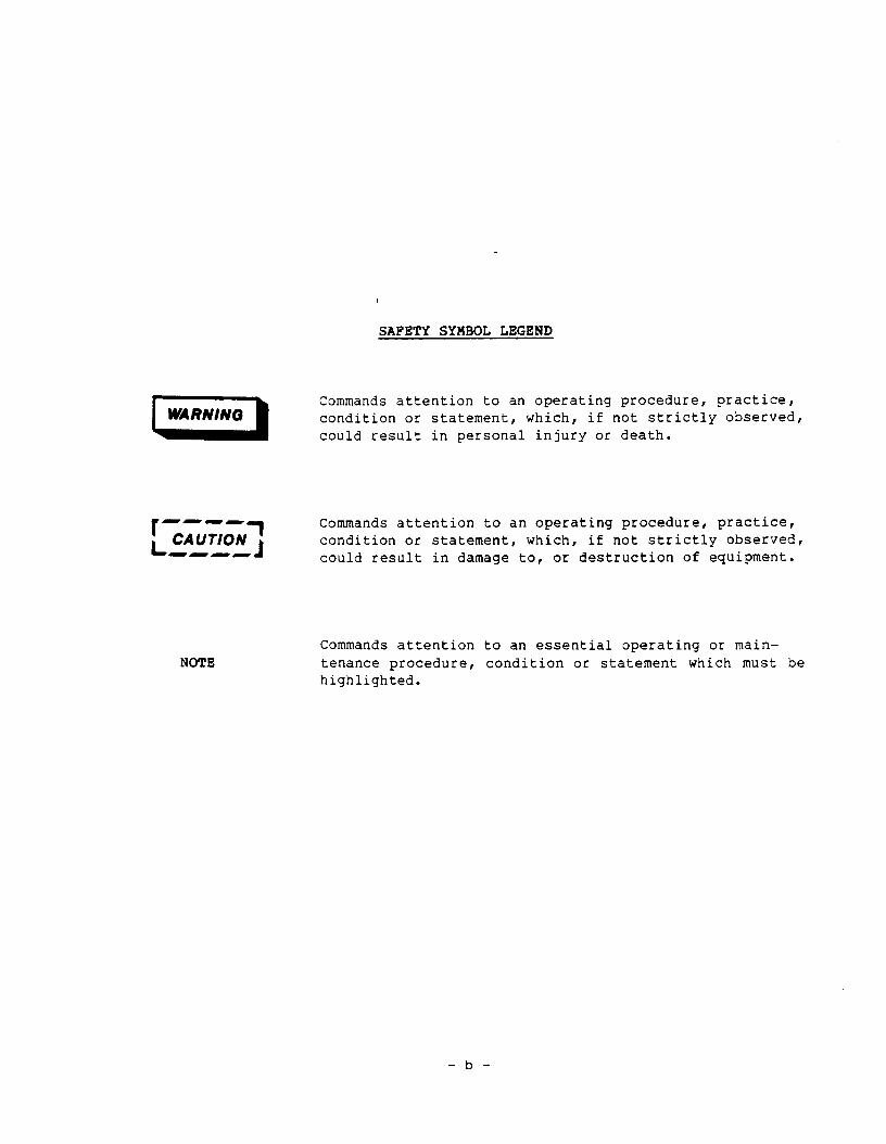
SAFETY SYMBOL LEGEND
I,,,,( Commands attention to an operating procedure, practice, condition or statement, which, if not strictly observed, could result in personal injury or death.
NOTE
Commands attention to an operating procedure, practice, condition or statement, which, if not strictly observed, could result in damage to, or destruction of equipment.
Commands attention to an essential operating or main- tenance procedure, condition or statement which must be highlighted.
-b-
ISSUE DATE - HAY, 1985 BBVISBD DATE - OCTOBER, 1987
GEK-14870 E
NOTICE
The information herein does not purport to cover all details or variations in equipment nor to provide for every possible contingency to be met in connection with installation, operation and maintenance. Should further information be desired or should particular problems arise which are not covered sufficiently for the purchaser’s purposes, the matter should be referred to General Electric Company, Drive systems Operations, 1501 Roanoke Boulevard, Salem, Virginia, USA, 24153.
NOTICE
This document contains proprietary information of General Electric Company, USA and is furnished to its customer solely to assist that customer in the installation, testing, and/or maintenance of the equipment described. This document shall not be reproduced in whole or in part nor shall its contents be disclosed to any third party without the written approval of General Electric Company, Drive Systems Operations, 150 1 Roanoke Boulevard, Salem, Virginia 24153, U.S.A.
-a-
GEK - 14870 ALTERREX EXCITATION SYSTEM STATIC CONTROL
TABLE OF CONTENTS
SECTION TITLES PAGE NO.
INTRODUCTION . . . . . . . . . . . . . . . . . . . . . . . . . . 1
RECEIVING, HANDLING AND STORAGE ................ 1
RECEIVING AND HANDLING ................... 1 STORAGE .......................... 1
DESCRIPTION . . . . , . . . . . . . . . . . . . . . . . . . . . 1
INSTALLATION .......................... 3 LOCATION AND MOUNTING ................... 3 CONNECTIONS ........................ 4
OPERATION ........................... 5 INITIAL OPERATION ..................... 5
Preliminary Checks ................... 5 Operational Tests With Simulated Exciter ........ 6
OFF-LINE TESTS, GENERATOR RUNNING ............. 10 Exciter Unloaded .................... 10 Exciter Loaded - Generator Field Energized ....... 14
ON-LINE TESTS . . . . . . . . . . . . . . . . . . . . . . . 23 Current Compensator Checkout . . . . . . . . . . . . . . 23 Underexcited Reactive Ampere Limit Adjustment . . . . . 25
SUBSEQUENT OPERATION (RESTARTS) . . . . . . . . . . . . . . 34
PRINCIPALS OF OPERATION .................... 35 GENERAL .......................... 35 EXCITER FIELD RECTIFIERS .................. 38 EXCITER VOLTAGE REGULATOR ................. 57 GENERATOR VOLTAGE REGULATOR ................ 61 EXCITER FIELD CURRENT LIMIT AND OVERCURRENT RELAYS ..... 73 REACTIVE CURRENT COMPENSATOR ................ 76 ACTIVE/REACTIVE CURRENT COMPENSATOR ............ 78 UNDEREXCITED REACTIVE AMPERE LIMIT ............. 82 RELAYING AND CONTROL CIRCUITS ............... 87 POWER RECTIFIER CUBICLE .................. 89 MISCELLANEOUS FUNCTIONS AND COMPONENTS ........... 89
MAINTENANCE . . . . . . . . . . . . . . . . . . . . . . . . . . 90
_ ii -

ALTERREX EXCITATION SYSTEM STATIC CONTROL GEK - 14870
TABLE OF CONTENTS
SECTION TITLES PAGE NO.
TROUBLESHOOTING ........................ 93 GENERAL ............ . ............. 93 POWER CIRCUITS ....................... 95 CONTROL CIRCUITS ...................... 97 TROUBLESHOOTING GUIDE ................... 98
RENEWAL PARTS . . . . . . . . . . . . . . . . . . . . . . . . . 100
ADDENDUM+1 .......................... 134 INITIAL OPERATION CHECKS .................. 135 STATIC DISCHARGE CIRCUIT TEST ............... 137 ALTERREX ENHANCEMENT PER TIL 961 - 3 ............ 139 OFF-LINE TESTS, GENERATOR RUNNING ............. 142
- iii -

ALTERREX EXCITATION SYSTEM STATIC CONTROL GEK - 14870
GEK - 14870 ALTERREX EXCITATION SYSTEM STATIC CONTROL
INTRODUCTION
The 3S7932EA210 Alterrex Excitation System Static Control controls the Voltage (of reactive volt-amperes) of an AC generator by controlling its excitation. This system uses a smaller AC generator as a power source for excitation. The AC voltage from this smaller AC generator is rectified by parallel banks of silicon rectifiers to furnish DC for the main generator field. For clarity the smaller AC generator will be called the exciter and the larger main generator rJil1 be called the generator.
The generator excitation is controlled by varying field current to the exciter. This exciter field current is controlled by a static voltage regulator. The regulator is a thyristor type using Silicon Controlled Rectifiers (SCRs) in the output circuit that drives the exciter field. The regulator includes both AC and DC (automatic and manual) control functions to regulate generator terminal voltage and generator field voltage, respectively.
The Alterrex system also includes various limit circuits, compensator circuits, startup circuits, and relaying.
RECEIVING, HANDLING AND STORAGE
RECEIVING AND HANDLING
Immediately upon receipt, the equipment should be carefully unpacked to avoid damage. Particular care should be exercised to prevent small parts from being mislaid or thrown away in the packing material.
As soon as the equipment, it should be examined for any damage that might have been sustained in transit. If injury or rough handling is evident, a damage claim should be filed immediately with the transportation company, and the nearest General Electric sales office should by notified promptly.
STORAGE
If the equipment is not to be used as soon as it is unpacked, it should be stored in a clean, dry place and protected from accidental damage. Particular care should be exercised to avoid storing the equipment in locations where construction work is in progress. If equipment is to be stored for more than three months, it should be kept heated to at least 5’C above ambient temperature to keep out moisture.
DESCRIPTION
The 3S7932EA210 is the control cubicle portion of an Alterrex excitation system. The AC exciter and power rectifier portions are covered by separate instructions.
- l-
ALTERREX EXCITATION SYSTEM STATIC CONTROL
DESCRIPTION (Continued)
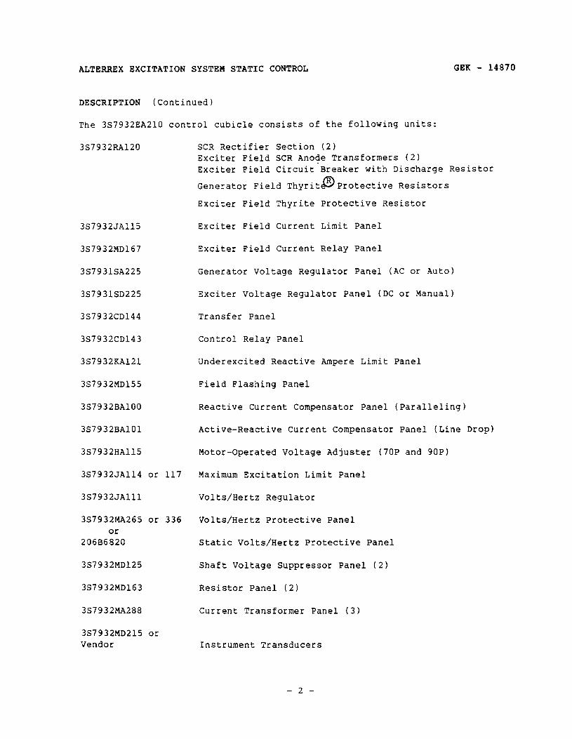
The 3S7932EA210 control cubicle consists of the following units:
3s7932RA120
3S7932JA115
3S7932MD167
3S7931SA225
3S7931SD225
3S7932CD144
3S7932CD143
3S7932KA121
3S7932MD155
3S7932BAlOO
3S7932BAlOl
3S7932HA115
3S7932JA114 or 117
3S7932JAlll
3S7932MA265 or 336 Or
206B6820
3S7932MD125
3S7932MD163
3S7932MA288
3S7932MD215 or Vendor
GEK - 14870
SCR Rectifier Section (2) Exciter Field SCR Anode Transformers (2) Exciter Field Circuit-Breaker with Discharge Resistor
Generator Field Thyrit @ Protective Resistors
Exciter Field Thyrite Protective Resistor
Exciter Field Current Limit Panel
Exciter Field Current Relay Panel
Generator Voltage Regulator Panel (AC or Auto
Exciter Voltage Regulator Panel (DC or Manual
Transfer Panel
Control Relay Panel
Underexcited Reactive Ampere Limit Panel
Field Flashing Panel
Reactive Current Compensator Panel (Paralleling)
Active-Reactive Current Compensator Panel (Line Drop)
Motor-Operated Voltage Adjuster (7OP and 9OP)
Maximum Excitation Limit Panel
Volts/Hertz Regulator
Volts/Hertz Protective Panel
Static Volts/Hertz Protective Panel
Shaft Voltage Suppressor Panel (2)
Resistor Panel (2)
Current Transformer Panel (3)
Instrument Transducers
-2-

GEK - 14870
DESCRIPTION (Continued)
ALTERREX EXCITATION SYSTEM STATIC CONTROL
3S7932YA122 or Vendor
3S7932YA131 or 3S7932YA200 Series or Vendor
3S7932RA121
3S7932MA272
3S7932MD182
3S7932RA119
3S7932ATlOO
3S7932MA189
3S7932MD143
3S7932LA202
3S7932MD121
3S7932MA305
Field Ground Detecting Relays
Field Temperature Indicator/Retransmitter
Static Switch Panel, Current Boost (2)
SCR Monitoring Panel (2)
De-Excitation Relay Panel
SCR Panel, De-Excitation (2)
Automatic Tracking Panel
Voltage Matching Panel
Automation or Accessory Relay Panel
Power System Stabilizer Panel
Voltage Balance Relay Panel
Exciter Phase Fault Detector Panel
On most applications, not all of the above panels are included. Also, special purpose panels may be supplied on some units. The de-ionized water-cooled power rectifier cubicles are usually mounted in the exciter house. They are models 3S7501FSlOO series, 3S7501FS200 series, and 3S7501FS300 series, covered by instructions GEK-9142, GEK-15198, GEK-36496, or other instructions. Associated control switches and instruments are usually shipped and mounted separately.
INSTALLATION
LOCATION AND MOUNTING
The control cubicle should be mounted so that it is accessible from both front and rear. This enclosure should be installed in a well ventilated, clean, dry location where normal ambient temperature is less than 50°C (122'F). Cooling water is not required for the control cubicle. When filters and fans are provided in the control cubicle, the filters must be cleaned often if the air is very dirty. Make all wiring connections to the control as specified on diagrams furnished for the particular installation.
-3-
GEK - 14870 ALTERREX EXCITATION SYSTEM STATIC CONTROL
INSTALLATION (Continued)
CONNECTIONS
1. Wire check all external connections to the excitation control and rectifier cubicles. (Refer to the customer connection diagram for the job, and/or Figure 25, Sheets 20 and 21.)
2. Check all connections and polarities to the current boost current transformers 4CT, 5CT, and 6CT. The current boost current transformer (CT) consists of a secondary winding and a separate trimmer winding wound on a common circular core, whose cross section area is small. The primary winding is the bus conductor between the exciter and the rectifier bridges. This conductor passes through the core, creating a one-turn winding.
The trimmer winding is occasionally used either in a series aiding connection or in a series opposing connection with the secondary winding: but most often, the trimmer winding is not used. When it is not used, should remain open-circuited. BY NO MEANS SHOULD THE TRIMMER WINDING SHORT-CIRCUITED. The reason for this will be explained in the PRINCIPLES OF OPERATION section of this book.
3. Check the polarities of the current transformer (CT) and potential transformer (PT) on the generator output connecting to the regulator. signal current transformer must be in the proper phase. The PT burden
it BE
The is
approximately 150VA maximum total (200VA with V/Hz Regulator Panel). The CT burden is 360VA maximum, at 5 amperes secondary at a PF of 0.9
4. Check both the generator and the exciter phase sequence.
5. Check all large rectifiers with an ohmmeter (in the exciter and generator field circuits).
6. Check the wire size of interconnecting wiring against the diagram furnished with the control.
I s---
1 L CAUTION
B--B
J
RECTIFIER HEAT SINKS ARE AT ABOVE GROUND POTENTIAL. ANY WIRING OR CIRCUITS TO BE HI-POTTED OR MEGGERED MUST FIRST BE DISCONNECTED FROM THE CONTROL CUBICLE. DO NOT HI-POT OR MEGGER ANY CIRCUITS IN THE CONTROL OR RECTIFIER CUBICLE.
-4-
GEK - 14870
OPERATION
ALTERREX EXCITATION SYSTEH STATIC CONTROL
I II-B
L CAUTION 3 ---v
MSOPERATION OF THE EXCITATION SYSTEM WHILE CONNECTED M THE GENERATOR FIELD CAN CAUiE SERIOUS DAMAGE TO THE EXCITATION COItPONENTS, GENERATOR, AND CONNECTED EQUIPMENT. DEVIATIONS FROM THE FOLLOWING OPERATIONAL CHECKS AND PROCEDURES SHOULD BE CONSIDERBD IN THE LIGHT OF THIS, AND SHOULD BE DISCUSSED WITH THE MANUFACTURER PRIOR TO INITIATION. (REFER TO GEK-45907, GENERATOR OPERATION, FOR LIMITS OF GENERATOR OPERATION.)
INITIAL OPERATION
All controls have been preset at the factory. If any of the calibration procedures described below are not to be performed following installation, the factory setting of the pertinent control should be retained. A record of the system parameters and factory adjustments is provided on some jobs on a sheet of the elementary diagram. Space is also provided on this sheet for field settings to be recorded.
Zxcept in unusual operating circumstances, the factory setting should agree with that obtained in the calibration procedures described below.
Preliminarv Checks
1.
2.
3.
4. Check operation of 43CS (transfer) switch and all associated relays.
5. check that the flashing circuit will apply DC to the exciter field circuit.
6. Check operation of overtemperature circuits (lights, relays, and alarms).
7. Check operation of all protective relays. some of these are covered in detail later.
8. Check ground detecting 1: elay( s ) .
Energize DC for relay power. Check polarity.
Check operation of generator field breaker (if supplied) and exciter field breaker; also de-excitation relay, where supplied.
check operation of motor-driven adjusters - manual (DC) control and auto (AC) control (if motorized).
-5-

GEK - 14870 ALTERREX EXCITATION SYSTEM STATIC CONTROL
OPERATION (Continued)
Operational Tests with Simulated Exciter
Proper operation of the regulator can be achieved if this test is omitted, but the time which can be saved during unit startup by discovering possible equipment damage or wiring errors prior to-startup is certainly justified. If no errors or damage are discovered, the increased confidence in the regulator is a worthwhile gain. However, the procedure requires from two to ten hours, and equipment which may not be readily accessible in the generating station.
The exciter armature is replaced by a 3-phase, 60Hz source of either constant or variable amplitude. Its amplitude should be greater (line-to-line, rms) and less than 600V. The capacity of the at least 1.5KVA.
The exciter field is replaced by a dummy load resistance of This resistor should be capable of carrying 10A continuously.
than 1OOV source should be
10 to 25 ohms.
THIS EQUIPMENT CONTAINS A POTENTIAL HAZARD OF ELECTRICAL SHOCK OR BURN. ONLY PERSONNEL WHO ARE ADEQUATELY TRAINED AND THOROUGHLY FAMILIAR WITH THE EQUIPMENT AND THESE INSTRUCTIONS SHOULD INSTALL, OPERATE, OR MAINTAIN THIS EQUIPMENT.
1.
2.
3.
4.
5.
6.
7.
Disconnect the exciter leads from terminals R98, R99, and RlOO and connect the 3-phase source to these terminals, in phase sequence R98-R99-RlOO.
Disconnect the exciter leads from terminals R96 and R97 and connect the dummy load resistor to these terminals. Connect a DC voltmeter across the resistor (R97 negative).
Close switches DZSW and D4SW. Close either RlSW or R2SW, but not both.
Apply DC and AC control voltage to the cubicle.
The transfer relay, 43A, must be
Operate 70CS to drive 70P to its
When the exciter field breaker operate. Correct operation will
de-energized (43CS must be in MANUAL).
full lower position.
is closed, the flashing circuit will be indicated by the appearance of 50 to
1OOV on the dummy load upon closure of the field breaker. After about 10 seconds the flashing contactor will drop out and this voltage will disappear.
-6-
GEK - 14870 ALTERREX EXCITATION SYSTEM STATIC CONTROL
OPERATION (Continued)
8. When the 3-phase AC source is applied, the following indications should be observed at the SCR rectifier section whose disconnect switch is closed.
NOTE: The disconnect switch (R1S.W -and/or R2SW) can be used to apply the AC source. With this switch open, only the internal wiring between R98, R99, and RlOO and the incoming poles of the switch are energized. However, this switch does not break the exciter AC power to the regulator panels, the maximum excitation limit panel, and the transfer panel (for N2VM), and possibly to other special panels.
a. The gate clipping voltage, as indicated on R3VM, will rise to approximately 24VDC.
b. (1) Units with neon lamp SCR monitors: If the anode transformer secondary voltage is greater than 8OV, the neon lamp monitor across each SCR should light with the six lamps glowing with equal brilliance. Each of the two electrodes inside the bulb should also appear to glow with the same intensity.
(2) Units with light-emitting diode SCR monitors: If the anode transformer secondary voltage is greater than 4OV, the green and red (or yellow) LEDs should glow with almost equal intensity.
C. The output of the exciter voltage regulator, as indicated on DlVM, should increase to a value between 10 and 20VDC. On units with a de-excitation circuit, DlVM is limited to 9.8V.
d. The exciter voltmeter, N2VM, should read the value of the AC voltage applied. RlVM should read zero. If RlVM is pegged upscale, the disconnect switch should be opened immediately. If its reading is less than full scale, the disconnect switch may be kept closed while the trouble is investigated.
First, be sure DlVM is in its proper range. If it is, then the trouble is in the wiring between the regulator panel and the six SCR firing circuits, including relay 43A. This can be easily checked with a portable voltmeter. (Refer to Sheet 2 of the elementary diagram of the equipment if they are .D" size. If the diagrams are "C" size, refer to Sheets 9, 11 and 12.) If the diagrams are "B' size, refer to Sheets 03E through 03P and 06A.
If DlVM remains near zero, check the true position of 7OP. If it is at its lower limit, check the voltages within the exciter voltage regUlatOr
as compared with the voltages in Figure 14. This will quickly identify the faulty wiring or component.
-7-
ALTERREX EXCITATION SYSTEM STATIC CONTROL GEK - 14870
OPERATION (Continued)
9. When proper operation is observed, raise 70P while reading DlVM. As 70P reaches the regulatory position corresponding to the applied AC source voltage amplitude, the regulator output voltage will begin to drop. Move 70P slowly as this voltage nears IVDC. Set 70P to obtain an on-scale reading of RlVM. If the AC source is not stiff, the regulator will exhibit a snapping behavior characteristic of a loosely connected open loop regulator. As the regulator begins causing the SCR bridge to draw current from the source, the source voltage drops in amplitude. The regulator, sensing this, acts to cause the bridge to draw even more current. This process continues until the SCRs are firing full on and the regulator cannot cause an increase beyond this condition. Therefore, SCR firing instability caused by variations in the applied AC Voltage amplitude indicates proper regulator action.
10. Observe the reading of ammeter RlAM to show correspondence with the resistance of the dummy load and the SCR output voltage on RlVM.
11. Observe the current boost bridge voltage on RZVM where it is furnished: use a VOM on newer jobs. It should show 1 to 2 volts with RR-5 positive relative to RR-l.
12. If the voltage is sufficiently high, one electrode in the neon lamps should glow more brightly, or the red (or yellow) LED should be brighter than the green LED. At high firing angles (DlVM less than IV) one electrode (or the green LED) will not glow at all. All six indicators should appear to be identically lighted.
If DlVM varies as it should, but the rectifier meters and/or indicators show improper operation, check for shorted and/or open rectifier cells with a portable DC/AC voltmeter. Each cell in the current boost bridge should be forward biased about 0.8VDC and should indicate no AC voltage across it. Each SCR should indicate the same amplitude of DC voltage and the same amplitude of AC voltage. There should be no voltage across a fuse. A cell or fuse which gives an improper meter reading should be checked upon being disconnected from the circuit after first opening the disconnect switch.
If DlVM does not vary as it should, check the regulator internal voltages against those given in Figure 14.
As 70P is raised, if RlVM voltage rises to its maximum value while DlVM reads 3.5V or greater, this indicates that the phase sequence may be incorrect.
13. An oscilloscope may be used to check voltages in the circuit. The output voltage of the SCR bridge and the SCR rectifier bridges together should appear as shown in Figure 6. The firing circuit voltages should appear as shown in Figure 8.
-8-
GEK - 14870 ALTERREX EXCITATION SYSTEM STATIC CONTROL
OPERATION (Continued)
14. After proper operation has been obtained, lower 70P to its full lower position, open the disconnect switch and close the disconnect switch on the other SCR rectifier section. Then check out its operation in the same manner as previously described. After it has been observed to operate properly, close both disconnect switches and observe that both banks operate properly together. Current division will be difficult to determine accurately but should be in the ratio of 6:l or better.
NOTE: Current division is not necessary to the proper operation of the equipment. Each rectifier section is full-rated. However, both sections must be connected in order to obtain the benefit of the redundant circuits.
15. The generator voltage regulator panel may now be checked out using a 3-phase, 60 Hz. source of from 80 to 140VAC, rms, line-to-line. The same source may be used to supply the regulator front end (to R72, R73, and R74), as tne simulated exciter source at R98, R99, and RlOO. But this can cause interaction between the gain and stabilizing circuits in the regulator: these circuits are designed to act on cause and effect signals which vary in an opposite sense (a decrease in generator voltage results in an increase in exciter voltage), so when these signals are supplied from the same source, they must necessarily vary in the same sense. Such interaction will be evidenced by retarded response, then exaggerated snap action, or else by high frequency oscillation in the regulator amplifier circuitry. If these conditions develop, they can usually be eliminated by opening s,witch AZSW. A better approach is to provide separate AC sources for generator and exciter simulations.
16. If the generator regulator is to be checked out, close switches AlSW and A4SW, as well as DZSW and D4SW. Switch AZSW may also be closed, but this is not necessary. Open both rectifier disconnect switches RlSW and R2SW. Apply simulated exciter voltage and adjust 70P for about 3V on DlVM. Note that the transfer voltage, indicated on NlVM, is not meaningful until the simulated generator voltage is applied to the generator voltage regulator, and then NlVM reads the difference between the DlVM voltage and the AlVM voltage.
The high gain of the generator voltage regulator will cause the regulator output voltage to fluctuate rather rapidly whenever the simulated generator voltage is within the preset range of the generator voltage regulator.
If the simulated generator voltage is in the preset range of 106.4VAC to 123.6VAC, then the AlVM reading can be made 3V by adjusting 9OP. If outside the preset range, the range must be changed by moving range potentiometer AlOP (after carefully observing and recording its factory set position).
-9-

ALTERREX EXCITATION SYSTEM STATIC CONTROL GEK - 14870
OPERATION (Continued)
When 9OP and AlOP have been adjusted to obtain 3V on AlVM, recheck DlVM for 3V and adjust 70P if necessary.
17. Then observe AlVM and NlVM while slowly raising 9OP. AlVM should drop to approximately 0.5V while NlVM should-rise to + 2.5V. Fluctuation in these meter readings is not an indication of improper performance. Lowering 9OP should have the opposite effect. If the simulated generator voltage is variable, raising it a small amount should cause an appreciable increase in AlVM reading, and lowering it a small amount should reduce AlVM to almost zero.
18. While this much constitutes a sufficient checkout of the generator regulator, one or both banks of SCR rectifiers can be connected to the simulated exciter source, and operated in the MANUAL and AUTOMATIC modes, using 7OP, 9OP, and 43CS as desired to vary the firingangle.
Abnormal generator voltage regulator operation can be traced to the faulty parts using a voltmeter and the typical voltages shown on Figure 16. While observing these voltages, it is helpful to vary 9OP while holding the simulated generator voltage constant in order to follow the signal variation throughout the transistor amplifier components.
19. See Addendum #I (starting at page 134) for additional checks.
20. When all of the above checkout procedure has been satisfactorily accomplished, remove all added wiring and restore the exciter connections. Be sure to reset all potentiometers and controls to their factory set positions.
OFF-LINE TESTS, GENERATOR RUNNING
Exciter Unloaded
1. Preparation
a. Place the water flow ON for generator field rectifiers. Open the generator field rectifier disconnect switches.
b. Place the manual control (7OP) in full LOWER position.
C. Set the auto voltage adjuster (9OP) at midpoint.
d. Close switches DZSW - DISW and AlSW - A6SW. Close switch RlSW or switch RZSW, but not both.
e. Apply all auxiliary power to excitation system: DC relay power, AC power for lights, relays, etc.
- 10 -
GEK - 14870 ALTERREX EXCITATION SYSTEM STATIC CONTROL
OPERATION (Continued)
2. Exciter Voltage Regulator Checkout
a. Set 43CS on MANUAL position.
b. Close the exciter field breaker. _ Exciter voltage should build up to a low value. At this point, check the exciter phase sequence at terminals R98, R99, and RlOO. Improper phase sequence is not dangerous, but will restrict performance of the equipment. If DlVM reads 3.5V + lV, the phase sequence is probably correct. Note in these tests and in all further operation that when the regulator output voltage goes to zero, the SCRs will fire full on and the exciter voltage will increase rapidly. When the regulator voltage is about 3.5V, the SCR firing is delayed about 70°, and the normal bridge output voltage is developed. This is the approximate operating condition at any level of excitation. A regulator output voltage of about 5.2V will result in a delay of about llO”, and the SCR bridge average output voltage will be zero. When the regulator output voltage increases to about 11V: (Note: This is clamped to 1OV by D3ZD of the Static De-Excitation circuit) the SCR bridge will be fully inverting, developing its highest negative output voltage for the applied AC voltage. Inverting operation is possible only for inductive loads (such as the exciter field), and then only transiently. If the regulator output voltage should ever exceed 13V, firing pulses to the SCRs would cease. Then the AC line last switched (by an SCR) to the bridge positive bus would also remain connected. This connection would last until firing pulses started again, or until the output current decreased to zero. This undesirable condition is called single-phasing, as a single-phase (of the three AC phases applied to the bridge) will appear on the output buses.
C. The range potentiometers DlP and D2P should now be set according to the following procedure. Determine the desired excitation limits from the generator instruction book. The lower limit should be that required to obtain 0.82 per unit generator voltage, under no-load conditions, with the field cold (25OC). This is achieved on most generators by supplying 0.80 per unit no-load, rated voltage field current. The difference in the per unit numbers accounts for the slope of the generator saturation curve. The upper limit should be that required to obtain 1.03 times rated amperes, field, full-load, with the field resistance calculated at llO°C.
With these limits set on the exciter voltage regulator (DC regulator), voltage adjusting potentiometer 70P then will provide the capability to operate the generator from just below synchronizing excitation to its maximum continuous full rating excitation.
- 11 -
ALTERREX EXCITATION SYSTEM STATIC CONTROL GEK - 14870
OPERATION (Continued)
As an example, suppose AFNL (amperes, field, no-load) is 1620A, and the cold field resistance is 0.082 ohms. Then the field voltage required is 106V (1620A X 0.082 ohms X 0.80). The AC voltage. corresponding to this is 106 : 1,35, or 79VAC, rms, line-to-line. The lower limit should not be set less than 50VAC as the exciter voltage could collapse below this value.
The upper limit for this generator is determined from the AFFL (amperes, field, full-load) value, and the hot field resistance. For an AFFL of 4320A and a hot field resistance of 0.1088 ohms (1.3275 X 0.082 ohms), the field voltage will be 484 volts (1.03 X 4320A X 0.1088). The exciter voltage must be 484 : 1.35, or 359VAC.
Therefore, the range potentiometers should be set to regulate an exciter voltage of El = 79VAC with 70P at its lower limit, and E2 = 359VAC with 70P at its upper limit.
d. To do this it is necessary to obtain data for graphing DlP versus D2P (dial positions) in combinations which regulate El. After recordrng positions of DlP for D2P = 0, 2, 4, 6, 8, and 10, set the comolna:ion required for D2P = 4. Plot this data on the graph of Figure 1. All points may not be obtainable.
e. Then carefully raise 70P to its upper limit. Monitor the SCR rectlfler output voltage on an oscilloscope. The SCR firing should be staole; there should be no tendency for the waveform to jitter. The waveform should appear as in Figure 6b.
Observe all meters and note the increase in brightness of the neon lamps or LEDs.
f. When 70P reaches its upper limit, combinations of DlP and D2P, which regulate the higher voltage, E2, should now be obtained to graph anotner curve. Again find DlP settings required for D2P = 0, 2, 4, 6, 8, and 10 and graph this data on Figure 1, also. All points may not be obtainable.
g* The desired settings of the range potentiometers is established by the intersection of the graphs. With these settings locked in, check the repeatability of the regulator by lowering 70P to its lower limit, then raising it to its upper limit.
When the generator field circuit is open, the DC voltage available from the Alterrex system is 1.35 times the AC rms, line-to-line voltage supplied to the rectifiers. When the generator field circuit is closed, the DC voltage available is approximately 1.25 times the
- 12 -

GEK - 14870
OPERATION (Continued)
ALTERREX EXCITATION SYSTEM STATIC CONTROL
DIAL POSITIONS OF RANGE POTENTIOMETERS DlP AND D2P
1 COMBINATIONS TO t I REGULATE El I I DlP I D2P 1
I I3 I I I4 I
I I 6 I I I7 I I I 8 I I 9
IO
9
8
7
6
5 D2P
4
3
2
I
0
I COMBINATIONS TO 1 I REGULATE E2 I I DlP I D2P 1 I I 0 I
I I 2 I I I3 1
I I5 I I I 6 I I I 7 I
I I 9 I I I 10 I
0 12345678 9 IO
DlP
Figure 1: - DC Regulator Range Calibration
- 13 -
ALTERREX EXCITATION SYSTEM STATIC CONTROL GEK - 14870
OPERATION (Continued)
AC. But, since the front end of the exciter voltage regulator is a 3-phase full-wave bridge rectifier, electrically like the generator field rectifiers, and since these bridges are supplied from the same source, the sensing voltage of the regulator is a scaled-down version of the generator field voltage.
Consequently, the regulated exciter AC voltages will be higher when the main field disconnect switches are closed than they were when these switches were open. They will be higher by the ratio of 1.35 to 1.25, but the regulated DC voltage will be the same. Thus, in the example above, the exciter voltage will rise from 79VAC to 85VAC with 70P at its lower limit, and from 359VAC to 388VAC when 70P is at its upper limit. However, the corresponding generator field voltages will remain at 106VDC and 484VDC, as desired.
h. Close the other SCR rectifier disconnect switch and observe the ammeters. The current in each bridge will probably not be the same. The side with the higher gate clipping voltage will carry most of the current. The bridges are redundant and each has its own independent firing circuit. Thus, when an SCR fires before its companion, it suddenly picks up all of the exciter field current. When the companion SCR fires, it has to play catch up. By the end of the conduction interval, the current is almost equally divided between bridges, but the average current, as indicated on the ammeters, will be different.
Each bridge is full-rated; if one path opens, the remaining path can carry full current without overheating any components. If the high current side is switched out of service, after first making sure the other side is switched in, the other side will pick up the entire load without any appreciable change in excitation.
From this point on, leave both SCR bridges switched in - this establishes the redundant paths for maximum reliability.
1. Run 70P to its full lower position and trip the field breaker(s). On units where a de-excitation circuit is supplied, observe the change of state of the de-excitation relay, 41A.
Exciter Loaded - Generator Field Energized
DO NOT EXCITE GENERATOR UNLESS ALL METERING AND PROTECTIVE RELAYING HAS BEEN CHECKED (INITIALLY) AND IS IN SERVICE.
- 14 -
GEK - 14870 ALTERREX EXCITATION SYSTEM STATIC CONTROL
OPERATION (Continued)
1. Exciter Voltage Regulator
a. Close all generator field disconnect switches. Close field breaker(s). Generator terminal voltage should build up to approximately 82% of rated value.- Now 70CS should control generator terminal voltage.
b. A generator field rectifier section may be removed from service for maintenance or testing with the system energized. This can be done at any level of excitation, up to full-load current. Be sure that all sections are switched back in service immediately following the maintenance or testing operation in order to obtain the reliability provided by the redundant paths.
C. Determine that the Automatic Tracking Circuit is disabled. (ATS switch off).
2. Generator Voltage Regulator Checkout
a. With the generator terminal voltage at rated value, zero (deflect the pointer of the meter to zero) the transfer voltmeter (in parallel with NlVM) using voltage adjuster 9OP.
b. Move 43CS to the AUTO position. The generator voltage should remain the same as before. It should now be possible to raise and lower the generator terminal voltage with the AC voltage regulator adjuster, 9OP.
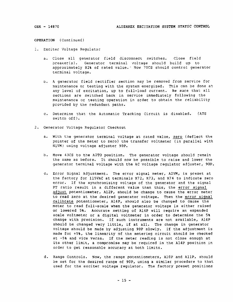
C. Error Signal Adjustment. The error signal meter, A2VM, is preset at the factory for 115VAC at terminals R72, R73, and R74 to indicate zero error. If the synchronizing voltage of the generator and the signal PT ratio result in a different value than this, the error signal adjust potentiometer, A12P, should be change to cause the error meter to read zero at the desired generator voltage. Then the error signal calibrate potentiometer, A14P, should also be changed to cause the meter to read full-scale when the generator voltage is either raised or lowered 5%. Accurate setting of A14P will require an expanded scale voltmeter or a digital voltmeter in order to determine the 5% change with precision. If such instruments are not available, A14P should be changed very little, if at all. The change in generator voltage should be made by adjusting 9OP slowly. If the adjustment is made for +5%, the linearity of the metering circuit should be checked at -5% and vice versa. If the meter reading is not close enough at its other limit, a compromise may be required in the A14P position in order to get reasonable accuracy at both limits.
d. Range Controls. Now, the range potentiometers, AlOP and AllP, should be set for the desired range of 9OP, using a similar procedure to that used for the exciter voltage regulator. The factory preset positions
- 15 -
ALTERREX EXCITATION SYSTEM STATIC CONTROL GEK - 14870
OPERATION (Continued)
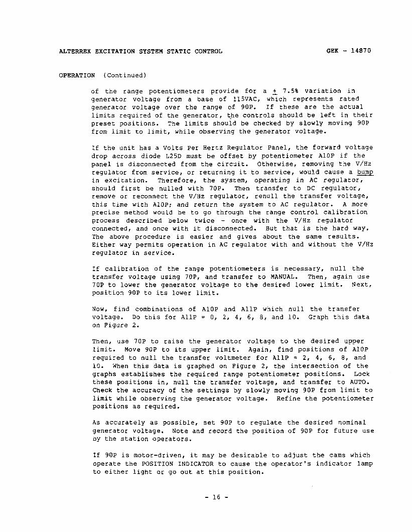
of the range potentiometers provide for a + 7.5% variation in generator voltage from a base of 115VAC, which represents rated generator voltage over the range of 9OP. If these are the actual limits required of the generator, the controls should be left in their preset positions. The limits should be checked by slowly moving 9OP from limit to limit, while observing the generator voltage.
If the unit has a Volts Per Hertz Regulator Panel, the forward voltage drop across diode L25D must be offset by potentiometer AlOP if the panel is disconnected from the circuit. Otherwise, removing the V/Hz regulator from service, or returning it to service, would cause a bump in excitation. Therefore, the system, operating in AC regulator, should first be nulled with 70P. Then transfer to DC regulator, remove or reconnect the V/Hz regulator, renull the transfer voltage, this time with AlOP; and return the system to AC regulator. A more precise method would be to go through the range control calibration process described below twice - once with the V/Hz regulator connected, and once with it disconnected. But that is the hard way. The above procedure is easier and gives about the same results. Either way permits operation in AC regulator with and without the V/Hz regulator in service.
If calibration of the range potentiometers is necessary, null the transfer voltage using 7OP, and transfer to MANUAL. Then, again use 70P to lower the generator voltage to the desired lower limit. Next, position 90P to its lower limit.
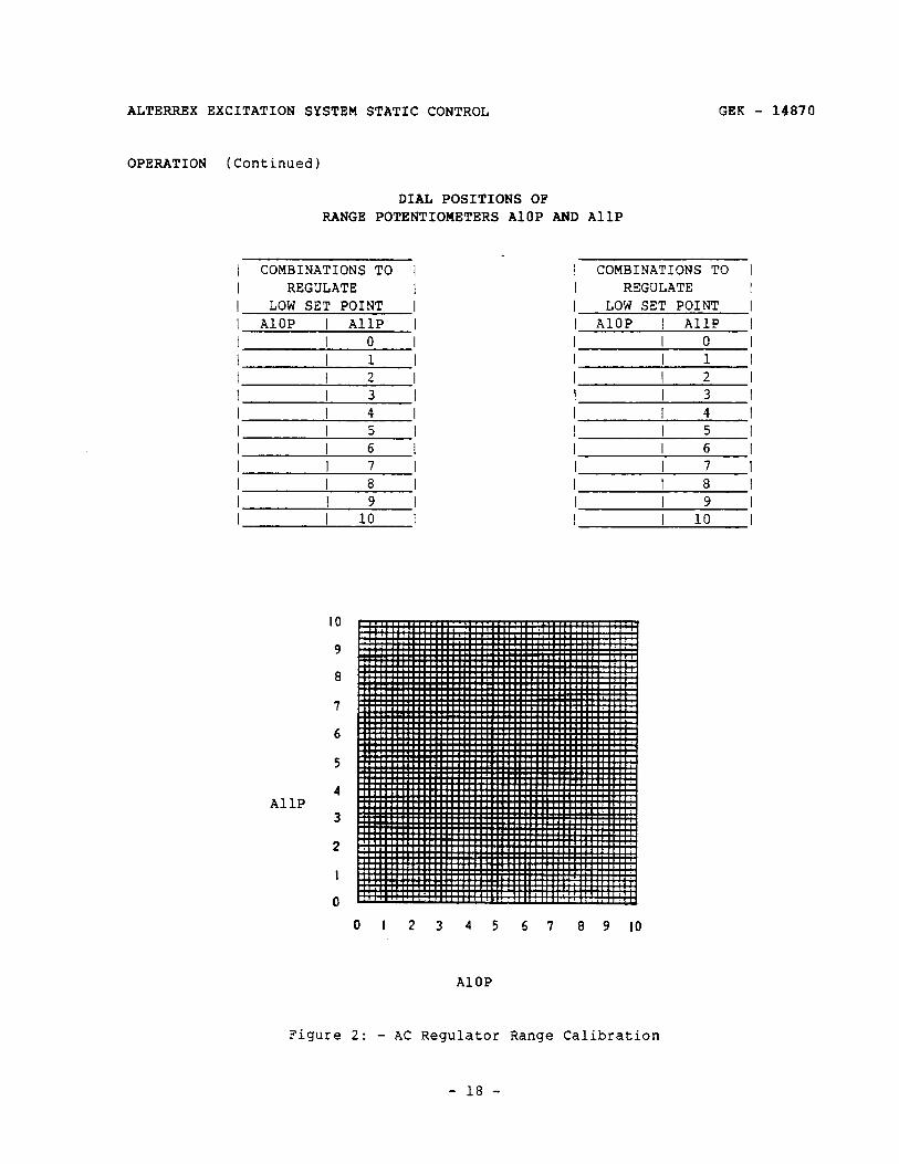
Now, find combinations of AlOP and AllP which null the transfer voltage. Do this for AllP = 0, 2, 4, 6, 8, and 10. Graph this data on Figure 2.
Then, use 70P to raise the generator voltage to the desired upper limit. Move 9OP to its upper limit. Again, find positions of AlOP required to null the transfer voltmeter for AllP = 2, 4, 6, 8, and 10. When this data is graphed on Figure 2, the intersection of the graphs establishes the required range potentiometer positions. Lock these positions in, null the transfer voltage, and transfer to AUTO. Check the accuracy of the settings by slowly moving 9OP from limit to limit while observing the generator voltage. Refine the potentiometer positions as required.
As accurately as possible, set 9OP to regulate the desired nominal generator voltage. Note and record the position of 9OP for future use by the station operators.
If 9OP is motor-driven, it may be desirable to adjust the cams which operate the POSITION INDICATOR to cause the operator's indicator lamp to either light or go out at this position.
- 16 -
GEK - 14870 ALTERREX EXCITATION SYSTEM STATIC CONTROL
OPERATION (Continued)
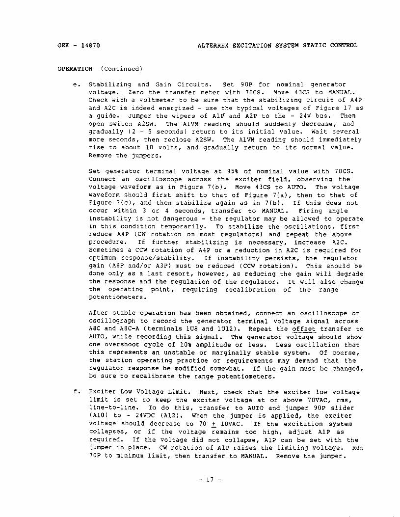
e. Stabilizing and Gain Circuits. Set 9OP for nominal generator voltage. Zero the transfer meter with 70CS. Move 43CS to MANUAL. Check with a voltmeter to be sure that the stabilizing circuit of A4P and A2C is indeed energized - use the typical voltages of Figure 17 as a guide. Jumper the wipers of AlP and A2P to the - 24V bus. Then open switch A2SW. The AlVM reading should suddenly decrease, and gradually (2 - 5 seconds) return to its initial value. Wait several more seconds, then reclose AZSW. The AlVM reading should immediately rise to about 10 volts, and gradually return to its normal value. Remove the jumpers.
Set generator terminal voltage at 95% of nominal value with 70CS. Connect an oscilloscope across the exciter field, observing the voltage waveform as in Figure 7(b). Move 43CS to AUTO. The voltage waveform should first shift to that of Figure 7(a), then to that of Figure 7(c), and then stabilize again as in 7(b). If this does not occur within 3 or 4 seconds, transfer to MANUAL. Firing angle instability is not dangerous - the regulator may be allowed to operate in this condition temporarily. To stabilize the oscillations, first reduce A4P (CW rotation on most regulators) and repeat the above procedure. If further stabilizing is necessary, increase A2C. Sometimes a CCW rotation of A4P or a reduction in A2C is required for optimum response/stability. If instability persists, the regulator gain (A6P and/or A3P) must be reduced (CCW rotation). This should be done only as a last resort, however, as reducing the gain will degrade the response and the regulation of the regulator. It will also change the operating point, requiring recalibration of the range potentiometers.
After stable operation has been obtained, connect an oscilloscope or oscillograph to record the generator terminal voltage signal across A8C and A8C-A (terminals lU8 and lU12). Repeat the offset transfer to AUTO, while recording this signal. The generator voltage should show one overshoot cycle of 10% amplitude or less. Less oscillation that this represents an unstable or marginally stable system. Of course, the station operating practice or requirements may demand that the regulator response be modified somewhat. If the gain must be changed, be sure to recalibrate the range potentiometers.
f. Exciter Low Voltage Limit. Next, check that the exciter low voltage limit is set to keep the exciter voltage at or above 70VAC, rms, line-to-line. To do this, transfer to AUTO and jumper 9OP slider (A101 to - 24VDC (A12). When the jumper is applied, the exciter voltage should decrease to 70 + 10VAC. If the excitation system collapses, or if the voltage remains too high, adjust AlP as required. If the voltage did not collapse, AlP can be set with the jumper in place. CW rotation of AlP raises the limiting voltage. Run 70P to minimum limit, then transfer to MANUAL. Remove the jumper.
- 17 -
ALTERREX EXCITATION SYSTEM STATIC CONTROL GEK - 14870
OPERATION (Continued)
DIAL POSITIONS OF RANGE POTENTIOMETERS AlOP AND AllP
I COMBINATIONS TO 1 I REGULATE I I LOW SET POINT 1 I AlOP I AllP I
I COMBINATIONS TO I I REGULATE I I LOW SET POINT I I AlOP I AllP I
I I 0 I I I 0 I I I 1 I I I 1 I I I 2 I I I 2 I I I3 I I I3 I I I4 I I I4 I I I5 I I I5 I I I 6 I I I6 I I I7 I I I7 I I I 8 I I I8 I I I 9 I I I 9 I I I 10 I I I 10 I
IO
9
8
6
4 AllP
3
I
0
Figure 2: - AC Regulator Range Calibration
01 2 3 4 5 57 8 9 IO
AlOP
- 18 -
GEK - 14870
OPERATION (Continued)
ALTERREX EXCITATION SYSTEM STATIC CONTROL
r I--- 1 L CAUTlON
---m J
IF THE TRANSFER TO MANUAL IS NOT WADE BEFORE THE JUMPER IS REMOVED, A LARGE RAPID CHANGE IN GENERATOR EXCITATION WILL OCCUR.
g* Current Limit Adjustment (Generator Field) (See Figure 15)
(1) Operate on MANUAL control.
(2) To set the overcurrent adjust, first check the calibration of the current limit circuit. Read the generator field current at minimum excitation. Simultaneously, read the voltage across AlOC (terminals A19 and A20).
Repeat these measurements with the excitation raised to 105% generator terminal voltage.
The theoretical voltage versus current equation is:
EAIOC = K1 + K21GEN FLD
This is a linear relationship between current and voltage, but voltage is not proportional to current. Because of this, two measurements at different excitation levels must be made.
If only one measurement is made and proportionality is assumed, then a considerable limit current error will accrue: the error will increase the actual limit current obtained above the desired value.
Designate the two data sets Ea and Ia, and Eb and Ib.
Calculate Ic = 1.4 times AFFL, generator. This is the desired limit current for generator field rectifier thermal protection.
Then calculate (Ic - Ib) (Eb - Ea) EC = Eb + (Ib - Ia)
This voltage must be between 110 and 180VDC. If the voltage is too low, set UlOR to maximum and check to see if the range is improved. If the voltage is still wrong, this usually indicates that the CT is phased wrong.
(3) Open A3SW, then connect an ungrounded output variable DC power supply (0 - 200VDC, 0.4A capacity) across AlOC (be sure to
- 19 -
ALTERREX BXCITATION SYSTEM STATIC CONTROL GEK - 14870
OPERATION (Continued)
connect the positive side to A19 or AlOC-1) and set for the voltage calculated above.
(4) With this voltage across AlOC, 43cS on MANUAL, and the transfer VM (TVM and NlVM) on zero, move Al3P CCW (slider toward A44R) until the current limit circuit begins to take over. This will be indicated by the transfer VM moving off zero. Lock A13P. The current limit is now set at 140% AFFL (Amperes, Field, Full-Load). Remove the power supply and close A3SW. If A13P should have insufficient range, it will be necessary to change the resistance of A44R.
h. Inverse Time Maximum Excitation Limit (Generator Field). See specified GEK.
i. Current Limit Adjust (Exciter Field)
This circuit has the same theoretical equation as circuit 'g', above. The calibration procedure is the same. Note I, = specified limit currer,t.
(1) Operate on MANUAL Control.
(2) Yeasure the DC voltage across ElC on the Exciter Field Current Limit Panel with 70P at the lower limit. Record this voltage and the exciter field current. Then remove one SCR rectifier section from service and repeat.
(3) Replace the SCR rectifier section in service, and remove the other one from service. Again, repeat the above measurements. The readings should agree. If not, check the wiring from the current limit CTS (13CT, 14CT, and 15CT) to the loading resistors and the rectifier circuit on the exciter field current limit panel. Repeat at 105% generator terminal voltage.
(4) The SCRs and rectifiers are sized to the exciter field current requirements for the particular installation, with regard to the response ratio required from the excitation system and with regard to adequate protection against over-excitation. Therefore, the SCR type can be used to determine the required setting for the current limit circuit, unless it is specified in the Data and Adjustments sheet of the elementary.
If the SCR porcelain body diameter is 1.00 inch, the limit current is 360A or less. If the SCR porcelain body diameter is 1.625 inches, the limit current is 500A or less. If forced air cooling is employed in the SCR rectifier section, the limit current is 720A or less. Newer models have the limit current stamped on a label on the panel; it is also specified on the Data
- 20 -
GEK - 14870 ALTERREX EXCITATION SYSTEM STATIC -Ii
OPERATION (Continued)
and Adjustments sheet of the elementary diagram of the control.
(5) Using the specified exciter field circuit limit current as I, and a similar procedure to the generator field current limit circuit calibration, calculate the calibrating voltage to be applied to Elc. It should be-about 76VDC.
(6) Connect an ungrounded output variable DC power supply (0 - 90VDC, O.lA capacity) across ElC in the same polarity as the measured voltage. Set the voltage to 90% of the value determined in (51, above, first.
(7) Then, with the transfer voltage on zero, slowly raise the power supply voltage until the transfer voltage begins to drop. If the power SUPPlY voltage at that point agrees with the value calculated in (51, then the potentiometer, ElP, is set correctly; if not, adjust E~P to its proper position and lock it in place.
j. Exciter Field Overcurrent Relay Adjustment.
(1)
(2)
Early 3S7932EA210 systems employed current relays in the exciter field DC circuit. These are located on a separate panel, 3S7932MD167. one of the relays, designated 76, has an inverse time characteristic. It was designed to operate in conjunction with the exciter field current limit circuit to allow forcing at the limit current for 60 seconds. At the end of this time, the relay will pick UP, transferring control to MANUAL. An intermediate current, between the threshold current of 180A (or 250A or 360A) and the limit current of 360A (or 50OA or 720A) will pick up the relay in a longer time. Relay 50 is a back up relay to the current limit circuit; it operates instantly at a Current of 400A (or 560A or 800A) or greater.
Newer 3S7932EA210 systems employ a static OVerCUrrent relay circuit for the two functions 76 and 50. These relays operate from the current limit circuit voltage across ElC. This circuit is included as a part of the Exciter Field Limit Panel, 3S7932JA115A3 or A4. Group A3 is set at the maximum SCR rectifier bridge capability (360A, 500A, or 720A). The CT loading resistor, E7R, consists of a fixed resistor and an adjustable resistor. The adjustable resistor is set to reduce the limit current from the values given above for increased protection against overexcitation. (See Figure 18).
The limit current on group A4 will be stamped on a label on the panel; the required resistance adjustment will be factory set to obtain that current. These settings will be discussed in more detail under the PRINCIPLES OF OPERATION section of this book.
- 21 -
ALTERREX EXCITATION SYSTFM STATIC CONTROL GEK - 14870
OPERATION (Continued)
All settings achieve the circuit voltage described in the following paragraph.
At a current less than or equal to the exciter field circuit rated current (this will always be greater than the exciter rated field current), the operational amplifier integrator will remain at negative saturation. The voltage across ElC will be 45V or less. Any current exceeding the above value will cause relay 76 to be energized, after a length of time. This time is inversely proportional to the excess current. one point on this inverse time characteristic is 60 seconds at twice the exciter field circuit rated current, which is the limit current. That current should generate 76.5 2 4v across ElC. Relay 50 operates instantaneously whenever the voltage equals or exceeds 84 + 3V. This corresponds to 2.222 times the exciter field circuit rated current: relay 50 should operate only when the current limit fails to operate.
(3) Adjustments. The old relay 76 can be adjusted to shorten its time of operation by uncovering more area in the dashpot cup for the silicone fluid to pass through. The threshold or holding current is adjusted by raising or lowering the initial position of the steel plunger in the coil/magnetic assembly. Old relay 50 can be adjusted by changing the spring tension or initial air gap. For the static circuit, relay 76 holding current adjustment is made with E2P, (may also be designated lP), and the time delay is adjusted by E3P, (may also be designated 2P); relay 50 is adjusted by E4P (or 3P). The circuit adjusted by E7R, and the limit current is
k. InVerSe Time Maximum Excitation Limit: Adjust
1. Volts/Hertz Protective Panel: For 3S7932MA265 GEK - 12519. For 3S7932MA336 panel, GEK 206B6820Gl panel, adjust per GEK - 84149.
voltage calibration is adjusted by ElP.
per GEK - 15014.
panel, adjust per - 36510 applies. For
m. Volts/Hertz Regulator (Where Supplied): Adjust per GEK - 36504 or GEK - 15021.
n. Voltage Matching Panel (Where Supplied): Adjust per GEK - 36442.
0. Automatic Tracking Panel (Where Supplied): Adjust 3S7932ATlOOA7 through A10 per GEK - 15025. Adjust 3S7932ATlOOAl1, Al3, and Al5 per GEK - 36485.
P* Generator and Exciter Field Ground Detector Panels: Adjust 3S7932YA122A9 per GEK - 36424.
- 22 -
ALTERREX EXCITATION SYSTEM STATIC CONTROL GEK - 14870
OPERATION (Continued)
4* Static Voltage Balance Panel: Adjust 3S7932MA350 per GEK - 36539.
f. Exciter Phase Fault Detector Panel (Where Supplied): Adjust 3S7932MA305A per GEK - 36524.
S. Transducers: 3S7932MD215A6, A7, or A8 - adjust per GEK - 36483.
t. Generator Field Temperature Indicator: 3S7932YA131 - adjust per GEK - 36484.
U. Power System Stabilizer (Where Supplied): Adjust 3S7932LAlOO series stabilizer per GEK - 14992. Adjust 3S7932LAZOZGZ stabilizer per GEK - 36416. Adjust 3S7932LAZOZG14 stabilizer per GEK - 83809. Adjust 3S7932LAZOZG15 stabilizer per GEK - 83808.
V. DS Exciter Field Breaker 206B4913 per GEK - 83785.
ON LINE TESTS
Current Compensator Checkout
1.
2.
3.
4.
5.
With the generator operating on MANUAL control, synchronize with the line. Pick up as much as 10% load, if possible.
Raise the MANUAL control 70P to cause the generator to supply 5 or 10% of its rating as VARs (overexcited).
Set the Reactive Current Compensator (RCC) and the Active-Reactive Current Compensator (ARCC) switches on zero (GlSW and GZSW).
Zero the TVM with 9OP.
Turn the GZSW COARSE knob on RCC through 5, 10, 15 to 20. The AlVM voltage reading R32B by opening R31A and R32A.
should increase. If the reading decreases, short R31B and the CT switch at those terminals and reverse the wires on
MAKE SURE THE PROPER TYPE OF SWITCH HAS BEEN SUPPLIED BEFORE OPENING IT. IT SHOULD SBORT THE INCOMING TERMINALS BEFORE OPENING THE OUTGOING (INTBRIOR) TERNINALS.
I ----
L CAUTION 3 ----
- 23 -
ALTERREX EXCITATION SYSTEM STATIC CONTROL GEK - 14870
OPERATION (Continued)
Final adjustment of the compensator can be made only after considerable experience with the generator operating under control of the regulator. It is desirable to keep the amount of compensation to the minimum required for proper division of VARs between generators to avoid excessive voltage regulation. As an initial adjustment,- it is advisable to turn the coarse adjustment knob to position 5 with the fine adjustment knob at 2.
More information is included under PRINCIPLES OF OPERATION. For the present, consider that the RCC transfers the location at which the voltage is regulated from the generator terminals to a point inside the generator. As more and more compensation is used, eventually the entire synchronous impedance drop is accounted for, and the resulting regulator is a fixed field regulator, which is the same as MANUAL, regulating the generator internal voltage. So, the RCC degrades the regulator performance.
Adjustments may be made with the compensator transformer energized (CT switch closed).
6. Turn the GZSW COARSE knob on ARCC through 5, 10, and 15 to 20. The AlVM voltage reading should decrease. If reading increases, short R31B and R32B by opening the CT switch and reverse the leads to terminals GxR and GxX. Close tne CT switch.
Return the reactance-adjusting knob to zero , and turn the resistance- adjusting knob, GlRH, to the right to increase resistance. This should also decrease the AlVM voltage.
Final adjustment of the compensator must be made on the basis of experience. Preliminary adjustment may be made in accordance with the known values of resistance and reactance for that portion of the system over whicn compensation is desired. If the voltage at the point which is to be compensated decreases as the power factor becomes more lagging and increases as the power factor becomes less lagging, more reactance and possibly less resistance may be required.
7. By comparison with the RCC, the ARCC makes the regulator a super- regulator, transferring the point at which the voltage is regulated from the generator terminals to a point beyond the generator, somewhere inside the output step-up transformer. Care must be taken that a limited amount of ARCC is used or the excitation system will be trying to maintain the voltage at a point in the system which is beyond the capability of the generator. Thus, a voltage error could not be satisfied by the excitation system, and it would go to ceiling excitation or floor excitation in an effort to satisfy the error.
8. The RCC and the ARCC should not be used together, as they offset each other.
- 24 -
GEK - 14870 ALTERREX EXCITATION SYSTEM STATIC CONTROL
OPERATION (Continued)
9. Return generator excitation to desired VARs and zero TVM with 9OP. Move 43CS to AUTO. Generator VARs should not change. 9OP should now control generator excitation and VAR output.
Underexcited Reactive Ampere Limit Adjustment
After satisfactory operation of the AC regulator has been obtained, the reactive ampere limit must be tested. Place the compensator (RCC/ARCC) switches at zero before beginning this test.
1. Limit Polarity
a. Operate on MANUAL control. Set the REACTIVE AMPERE LIMIT POWER RECALIBRATION switch, BlSW, at zero and the REACTIVE AMPERE LIMIT START dial, BlVT, at its highest numbered position. Note that BlVM reads about one volt negative.
To prevent the exciter low voltage limit from taking over from 9OP, and therefore preventing the URAL from outputting a signal, jumper the slider of AlP (anode of A13D) to the - 24V bus.
b. With the generator carrying load, adjust 70P for some safe value of under-excited reactive current. Adjust 9OP for zero TVM volts. Slowly turn the REACTIVE AMPERE LIMIT START dial towards zero. At some setting of the dial, the limit signal meter, BlVM, reading will go to zero and increase in the up scale direction and the AlVM voltage will decrease.
While changing the Limit Start dial, the PT loading decreases, causing AlVM to increase and TVM to decrease. This is a second-order effect. It should be ignored, or 9OP changed to re-null the TVM.
If the system voltage restricts the incoming VARs to a value too low to offset the URAL, it can be reconnected temporarily to check the limit polarity and stability at higher excitation levels, even with outgoing VARs. To do this, operate in MANUAL: then lift the panel wire from B3T (transformer) terminal 4, and reconnect it to B3T terminal 3. This will result in two wires on terminal 3. Be sure to move the panel wire and not the transformer lead. Continue the tests through section 2 with this connection, and then return the wire to terminal 4.
C. If the AlVM voltage increases, the limit DC output is reversed. Reverse connections B5 and B6 between the limit sensing circuit and the limit amplifier (AC regulator panel). Repeat the previously described test to secure proper results.
- 25 -
ALTERREX EXCITATION SYSTEM STATIC CONTROL GEK - 14870
OPERATION (Continued)
d. If the limit signal cannot be increased up scale from zero by turning the REACTIVE AMPERE LIMIT START dial to zero, open AlSW and reverse the primary connections of transformer B3T. Repeat the test to determine if positive limit signal voltage can be obtained by turning the REACTIVE AMPERE LIMIT START dial towards zero. THIS TEST MUST GIVE PROPER RESULTS BEFORE FURTHER TESTS ARE CONDUCTED.
e. With the REACTIVE AMPERE LIMIT START dial so set that BlVM reading is slightly up scale (about 0.5 to l.OV) turn the POWER RECALIBRATION tap switch from zero toward point 9. If the generator is delivering power, the BlVM reading should increase further up scale and AlVM voltage should decrease as the POWER RECALIBRATION switch is turned toward point 9.
2. Initial Operation
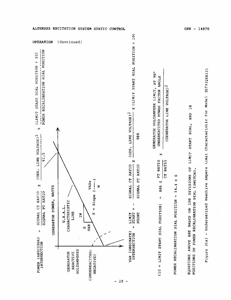
a. Operate the generator at normal voltage and with underexcited reactive current by adjusting 70P. Turn the REACTIVE AMPERE LIMIT START dial to its highest reading. Remove the jumper on A13D. Readjust TVM to zero with 9OP. Turn the 43CS control switch to AUTO. Slowly_ turn the REACTIVE AMPERE LIMIT START dial toward zero. At some point, AlVM reading should decrease slightly and exciter voltage should increase causing the under-excited reactive current to decrease. The dial setting at which the underexcited reactive current starts to decrease is the limit-start point. Check this point against the characteristic curve of Figure 3(a). These equations have been modified to account for the fact that the URAL output must increase to about 2.5V (instead of OV) before the AC regulator is affected. The modification results in the limit start dial position being decreased by ten. Also, if the limit cannot be obtained, BlSW may be increased as required. The observed and calculated points should agree within 10%. The exciter low voltage limit also imposes an underexcitation (VAR) limit. The shape of this limit characteristic is shown on Figure 3(a) as a dashed line. Be sure which limit is controlling excitation when obtaining points for the line.
b. If the operation is not as described, immediately remove the AUTO regulator from control of the generator excitation by turning the 43CS switch to MANUAL. Repeat the limit polarity tests. Do not proceed further until satisfactory operation is obtained.
C. With 43CS on AUTO, and the REACTIVE AMPERE LIMIT START dial at the limit start point, observe RlVM and generator reactive current for signs of oscillation. If oscillations appear, adjust the resistance A9P URAL feedback stability in series with the limit stabilizing capacitors A6C in 15% steps, approximately, first in the direction to decrease resistance (CW on most regulators), and then in the direction
- 26 -
ALTERREX EXCITATION SYSTEM STATIC CONTROL GEK - 14870
OPERATION ( Continued 1
to increase resistance.
If the limit is still unstable after the full range of resistance has been tried, the stabilizer capacitors A6-A through A6-D should be paralleled, then disconnected one at a time. The removal or addition of A6C-A should cause little change and thus provides fine control, while the removal or addition of A6-C or -D should cause a large change, providing a coarse control. Several capacitance steps can be obtained by selective combinations. After each change, the resistance should be adjusted in the same manner as previously described. If instability persists, decrease URAL gain by turning A8P CCW.
d. After stable operation of the limit has been obtained, and with the AC regulator in control of generator excitation, check the limit operation as follows:
(1) Move the REACTIVE AMPERE LIMIT START dial to the limit start point.
(2) Record the reactive current.
(3) Decrease the underexcited reactive ampere load on the generator by operating the voltage adjusting rheostat, 9OP, to raise the voltage. It should be possible to adjust the underexcited reactive current to any value lower than it was at the limit starting point.
Now increase the Underexcited Reactive Current by slowly turning the voltage adjusting rheostat, 9OP, to lower the voltage.
Note that AlVM voltage is first increasing, then returning to its operating point (about 3.5V) whenever 9OP is moved down.
As the limit start point is reached, the AlVM voltage should hold and it should be impossible to raise the reactive current appreciably above the previously recorded value no matter how far the voltage adjusting rheostat is turned in the direction to lower voltage.
e. As a final check of optimum limit stability, first raise 9OP past the point where the AlVM voltage just begins to drop. Then abruptly move the voltage adjusting rheostat in the lower direction and observe carefully the RlVM voltmeter and the reactive current meter for signs of oscillations. If oscillations appear, adjust for optimum stability as previously outlined. *When the RlVM voltmeter and the reactive current meter show only a few oscillations after an abrupt change of the voltage adjusting rheostat, the limit stability is satisfactory.
This completes the preliminary adjustment of the limit.
- 27 -
POWE
R (A
BSCI
SSA)
=
SIGN
AL CT
RA
TIO
X (G
EN.
LINE
VO
LTAG
El
X IN
TERS
ECTI
ON
SIGN
AL PT
RA
TIO
\ 61
.5
GENE
RATO
R PO
WER,
WA
TTS
\,
> U.
R.A.
L.
GENE
RATO
R CH
ARAC
TERI
STIC
RE
ACTI
VE
LINE
VO
LTAM
PERE
S
(UND
EREX
CITE
D:
NEGA
TIVE
) '
S =
Slop
e (-
---)
W
(LIM
IT ST
ART
DIAL
PO
SITI
ON
+ 10
)
POWE
R RE
CALI
BRAT
ION
DIAL
PO
SITI
ON
!z
VAR
(ORD
INAT
E)
LIMI
T SI
GNAL
CT
RA
TIO
(GEN
. LI
NE VO
LTAG
El
INTE
RSEC
TION
=
STAR
T =
- X
x (L
IMIT
ST
ART
DIAL
PO
SITI
ON
+ 10
) PO
INT
SIGN
AL PT
RA
TIO
886
GENE
RATO
R VO
LTAM
PERE
LI
MIT,
AT
90
" (l
o +
LIMI
T ST
ART
DIAL
PO
SITI
ON)
= 88
6 X
PT RA
T1o
X UN
DERE
XCIT
ED
POWE
R FA
CTOR
AN
GLE
CT RA
TIO
(GEN
ERAT
OR
LINE
VO
LTAG
El
POWE
R RE
CALI
BRAT
ION
DIAL
PO
SITI
ON
= 14
.4 x
S
EQUA
TION
S AB
OVE
ARE
BASE
D ON
10
0 DI
VISI
ONS
OF
LIMI
T ST
ART
DIAL
, AN
D 10
~o
sI~1
oNs
OF PO
WER
RECA
LIBR
ATIO
N DI
AL (S
WITC
H).
Figu
re 3(
a) -
Unde
rexc
ited
Re
acti
ve Am
pere
Li
mit
Char
acte
rist
ic fo
r Mo
del
3S79
32KA
121

GEK - 14870 ALTERREX EXCITATION SYSTEM STATIC CONTROL
OPERATION (Continued)
SIGNAL c.1. SECONDARY CURRENT AT LIMIT START POINT
=-GENERATOR VOLT-AMPERES AT LIMIT START POINT, 90 DEG. UNDEREXCITED POWER FACTOR ANGLE
-f3 X GENERATOR LINE VOLTAGE X C.T. RATIO
SIGNdL C.T. SECONDARY CURRENT (AT ANY OPERATING POINT)
= GENERATOR VCLT-AMPERES AT THE OPERATING POINT y3 X GENERATOR LINE VOLTAGE X C.T. RATIO
IN-PHASE SECONDARY CURRENT, I'p
OUT-OF-PHASE SECONDARY
(UNDEREXCITED)
POWER LE
POWER FACTOR ANGLE=90 DEG.
IN-PHASE SECONDARY CURRENT, I'p (AT ANY OPERATING POINT)
= GENERATOR POWFR (WATTS). AT THE OPERATING POINT -6 X GENERATOR LINE VOLTAGE X C.T. RATIO
OUT-OF-PHASE SECONDARY CURRENT, I’Q (AT ANY OPERATING POINT)
= GENERATOR REACTIVE VOLT-AMPERES NEGATIVE IF UNDEREXCITED
EXPECTED LIMIT CHARACTERISTIC LINE SLOPE =
POWER RECAl IBRATION DIAL POSITION 14.4
ACTUAL LIMIT CHARACTERISTIC LINE SLOPE =
CHANCE IN I' CHANGE IN I';
, BETWEEN TWO POINTS
ON THE ACTUAL CHARACTERISTIC LINE
FACTOR = ODEG.
Figure 3(b) - Underexcited Reactive Ampere Limit Calibration and Measured Performance
- 29 -

ALTERREX EXCITATION SYSTEM STATIC CONTROL GEK - 14870
OPERATION (Continued)
3. Final Adjustment of Limit
This is a very important function in the regulator. It must be set before committing the regulator to service. _ Using the relationships given in Figure 3(a) and the desired reactive KVAR limit and slope, calculate the signal CT secondary current intersections on the coordinates of Figure 3(b). The desired KVAR limit and slope should have been previously determined from generator and system stability requirements, as outlined below.
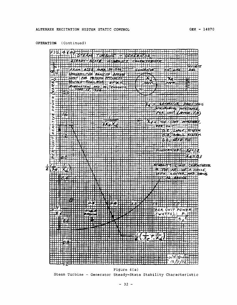
a. Figure 4(a) shows how to determine the steady state stability limit of a generator. The important features of this figure are the intercepts. The Y (or VAR) intercept is minus l/Xd per unit. This is the short- circuit ratio of the generator, using the saturated value of Xd. The X (or WATT) intercept is the reciprocal of the geometric mean of Xd and Xe, the tie line impedance to the so-called infinite bus. Xe cannot be less than the impedance of the generator output step up transformer, if it is unit-connected. For a large unit-connected generator/transformer and a large power system, a rough rule is Xe = X3/6; then the WATT intercept is 2.45/Xd.
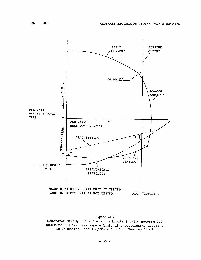
Figure 4(o) shows how to position the URAL line into the permissible operating regime of the generator. The URAL should be set with margin to the mast limiting curve, whether it be stability limit or core end iron neating limit. This applies at each intercept.
In the ansence of such information, the KVAR limit at 0 power factor should 3e set at no more than 0.6 times the KVAR limit at 0 power factor imposed by the armature core end heating: the limit line should cross the 1.0 power factor axis at no more than 1.2 times the generator rated KVA.
As an example, suppose it is required to set the URAL to limit the generator KVAR at 0 power factor to 200,000, and for the URAL line to intersect the 1.0 power factor line at 780,OOOKW. If the signal PT ratio is 24,000 : 120, and the signal CT ratio is 25,000 : 5, the signal CT secondary currents corresponding to the above operating points are 0.96A and 3.75A, respectively.
0.96A = 200,000,000 1.732 X 25,000 X 24,000
5
The slope required is 200,000,000 or 0.96 780,000,000 , 3.75 , which is 0.256.
Then the limit start dial position is 2.29.
- 30 -
GEK - 14870 ALTERREX EXCITATION SYSTEM STATIC CONTROL
OPERATION (Continued)
(886 x 200x 200,000,000 - 10) 5,000 24,000 X 24,000
The power recalibration dial position is 3.69 (14.4 X 0.256). Therefore, position 2 or 3 must be used. Position 3 will be chosen.
The secondary currents corresponding to these settings are 0.902A, at 90° leading power factor, and:
4.69 x 2.76 = 4.31A, at 1.0 power factor. 3
b. The actual URAL characteristic should now be determined, by operating in MANUAL at the desired limit start reactive current, if possible. The exciter voltage may not be able to be maintained low enough to achieve this, however.
The URAL output meter will read about +2.5V whenever the dials are Set so that the generator operating point coincides with the characteristic curve. Therefore, set the dials to the calculated position and ad just 70P to cause BlVM to read + 2.5V. Determine the secondary current at this point and plot it on Figure 3(b). Repeat this measurement for increased loading on the generator (increased power factor), if possible, so that the actual URAL characteristic may be measured over a wide range of operation.
c. If the actual URAL characteristic line is not sufficiently close to the expected line, ad just the dials to achieve the desired characteristic. Recheck the characteristic and record these positions.
d. Finally, the stiffness of the limit should be checked. Use 70P to slightly over-excite the generator from the limit line. BlVM should read about 0.5V negative. Zero the transfer meter with 9OP and transfer to AUTO. Slowly move 9OP in the lower direction until BlVM is + 2V. Then measure the CT secondary current. Slowly turn 9OP to its full lower limit, and record the CT secondary current. It should not increase more than 5% from its previous value. An increase of more than 5% indicates that the limit gain is too low. If this is indicated, increase the URAL sensitivity by adjusting BlP and repeat the above test. If additional gain is needed, adjust A8P CW. Make sure the limit is stable by jogging 9OP into the limit, as before.
e. Return the desired compensator to service.
f. Check the inverse time maximum excitation limit (generator loaded) per GEK - 15014.
- 31 -
ALTERREX EXCITATION SYSTEM STATIC CONTROL
OPERATION (Continued)
GEK - 14870
Figure 4(a) Steam Turbine - Generator Steady-State Stability Characteristic
- 32 -
GEK - 14870 ALTERREX EXCITATION SYSTEM STATIC CONTROL
PER-UNIT REACTIVE POWER, VARS 0
SHORT-CIRCUIT RATIO
FIELD
RATED PF
PER-UNIT - REAL POWER, WATTS
URAL SETTING
HEATING
STEADY-STATE STABILITY
TURBINE OUTPUT
/
*MARGIN TO BE 0.05 PER UNIT IF TESTED AND 0.10 PER UNIT IF NOT TESTED. MLC 7209110-2
Figure 4(b) Generator Steady-State Operating Limits Showing Recommended Under-excited Reactive Ampere Limit Line Positioning Relative
To Composite Stability/Core End Iron Heating Limit
- 33 -
ALTERREX EXCITATION SYSTEM STATIC CONTROL GEK - 14870
OPERATION (Continued)
SUBSEQUENT OPERATION (RESTARTS)
On jobs where a de-excitation circuit is supplied, observe all parts of it for proper operation whenever the exciter field breaker trip command is given. The SCR bridges should phase back, and the current boost bridges should be shorted.
1. Apply all auxiliary and control power to the excitation system.
2. Field breaker(s) open
3. 43CS on MANUAL
4. 70CS in full lower position
5. All rectifier disconnect switches closed - All regulator disconnect switches closed
6. Cooling water on
7. When equipment is near operating speed, apply excitation by closing the field breaker.
8. Bring the generator voltage up to rated with 70CS.
9. Zero TVM voltage with AC regulator voltage adjusting rheostat 9OP.
10. Move 43CS to AUTO. Then proceed with the synchronizing procedure to put the generator on the line. With V/Hz Regulator 3S7932JAlllA2, going on line in AUTO will cause the generator to put out VARs to the power system immediately (a bump); with group A7 of this panel, this will not occur.
11. When operating on AUTO AC regulator, the 9OP voltage adjuster is used to set the level of generator terminal voltage: thus it controls the reactive load on the generator. Adjuster 70P should be changed as often as required to keep TVM reading zero volts, so that excitation will remain constant if the AUTO regulator should trip. Some users may desire to set 70P at some predetermined (high) position while operating on AUTO regulator.
12. If it is necessary to operate on MANUAL DC regulator on the line, then 70P will control reactive load on the generator. Potentiometer 9OP should always be adjusted to zero TVM before going to AUTO.
- 34 -
GEK - 14870 ALTERREX EXCITATION SYSTEM STATIC CONTROL
PRINCIPLES OF OPERATION
GENERAL
The 3S7932EA210 Alterrex Excitation System controls the voltage (Or reactive volt-amperes) of an AC generator by controlling its excitation. This system uses a smaller AC generator as a power source for excitation. The AC voltage from the smaller AC generator (exciter) is rectified by a group of power rectifiers to furnish DC for the main generator field.
Generator excitation is controlled by varying field current to the exciter. The exciter field excitation is controlled by a static voltage regulator. The regulator is a thyristor type using silicon controlled rectifiers (SCRs) in the output circuit that drives the exciter field. The regulator includes both AUTO and MANUAi control functions to regulate generator terminal voltage or generator field voltage respectively.
The excitation s:Jstem is illustrated by the block diagram, Figure 5. The exciter is self excited since power is taken from its output terminals (through an anode transformer and thyristor circuit) to furnish DC for its field. The DC field current flowing through the diode rectifier circuit is normally more than the input AC current from the current boost CTs. Thus the diode rectifier circuit develops no voltage. Exciter field current control is the result of pnase controlled output from the SCR circuit.
The SCR control signal comes from the AC regulator or DC regUlatOr as selected by the transfer panel. When operating on MANUAL control, the DC regulator holds constant generator field voltage. When operating on AUTO control, the AC regulator holds constant generator terminal voltage. A transfer voltmeter is used for matching signals to provide for smooth transfer between the two regulators.
1. Exciter Voltage Regulator or DC Regulator
The inputs to the DC regulator include a feedback signal from the exciter voltage and a current input to act as an auxiliary power source during transient conditions when the exciter voltage may be low.
2. Generator Voltage Regulator or AC Regulator
a. The inputs to the AC Regulator are:
(1) a feedback signal from generator terminal voltage,
(2) a feedback signal from exciter terminal voltage for the minimum voltage limit circuit and for rate stabilizing circuits,
(3) a signal from exciter line current for the generator field current limit circuit and for auxiliary regulator power,
- 35 -

ALTERREX EXCITATION SYSTEM STATIC CONTROL GEK - 14870
1 I L__i-__-
t ---____ ----J ,$
,” I J
- 36 -
GEK - 14870 ALTERREX EXCITATION SYSTEM STATIC CONTROL
PRINCIPLES OF OPERATION (Continued)
(4) a takeover signal from the underexcited reactive ampere limit panel,
(5) a takeover signal from the current limit circuit of the exciter field SCR rectifier bridges, -
(6) a takeover signal from the volts/Hertz regulator panel,
(7) a circuit recalibrating element applied by the generator maximum excitation limit panel, and
(8) compensation signals from the reactive current compensator and the active-reactive current compensator.
b. The excitation system, under control of the AC regulator, has been classically called the voltage regulator. Voltage regulation is still the principal function of this regulator, but in a strict sense, this is only one of its many functions. The regulator incorporates logic circuitry which enables it to decide to regulate one of seven input or internally generated variables. These are:
(1) Modified (compensated) generator terminal voltage. The regulator action here is continuous - excitation will be continuously varied, in either an increased or a decreased direction, as required to maintain the compensated generator voltage constant.
The Reactive Current Compensator (RCC) provides a signal to modify the generator voltage input signal as required to achieve good paralleling of the generator with the power system. The Active-Reactive Current Compensator (ARCC) provides a signal (to one or several generators) to modify the generator voltage input signal as required to compensate for line drop; thus, it regulates voltage at some remote point in the power system.
(2) VARS. Excitation will be prevented from being reduced below the limit line according to the characteristic line of the URAL.
(3) Generator Field Current. This is also a limiting action, with two levels. The current will not be allowed to exceed the value set previously under Current Limit Adjustment - Generator Field.
In addition, the limit current will be reduced to AFFL after prolonged exciter overvoltage, on regulators which are equipped with the maximum excitation limit panel.
(4) Exciter Field Current. This regulation is alSO limiting, not continuous. The total current in the SCR rectifier bridges will not be allowed to exceed the value set earlier under Current
- 37 -

ALTERREX EXCITATION SYSTEM STATIC CONTROL GEK - 14870
PRINCIPLES OF OPERATION (Continued)
Limit Adjustment - Exciter Field.
(5)
(6)
(7)
Exciter Voltage. The exciter voltage will be prevented from being reduced below the value set under Exciter Loaded - Generator Field Energized, Paragraph 2f.
The ratio of generator voltage to frequency on regulators equipped with a volts/Hertz regulator panel. The regulator will reduce the excitation as the frequency is reduced, when the AC regulator is in service, whenever the generator frequency is below the takeover frequency set per instruction book GEK - 15021 or GEK - 36504.
The firing angle of the SCRs. This regulator action is limiting, the limit being set at the factory so that the SCRs cannot be phased back so far that they are not fired at all.
Also note that the de-excitation circuit, where furnished, is activated by the trip signal at the exciter field breaker. This circuit causes the regulator to phase back the SCR bridges, and it also short-circuits the current boost bridges. It backs up the field breaker and has no effect when the field breaker operates properly.
EXCITER FIELD RECTIFIERS
DC for the exciter field is furnished by two parallel rectifier circuits, each including a 3-phase full-wave diode circuit and a 3-phase full-wave SCR circuit. Either of the parallel rectifier circuits can be disconnected for maintenance during operation by a twelve pole switch. Either rectifier circuit will provide exciter field current without limitations while the other circuit is out of service. The SCR circuit normally provides controlled DC voltage for the exciter field while the diode circuit provides DC voltage only during transient conditions.
1. SCR Circuit
The SCR circuit operates as a phase controlled variable DC voltage source to control exciter field current as required by the AC and DC regulator. (Refer to Figure 6.)
a. Power Circuit
The input voltage to the SCR circuit is taken from the exciter output through anode transformer RlT, whose ratio is usually 400 : 150 (step down) providing a source voltage that will allow the SCRs to operate at about half the maximum (full-on) positive DC voltage. This typical
- 38 -
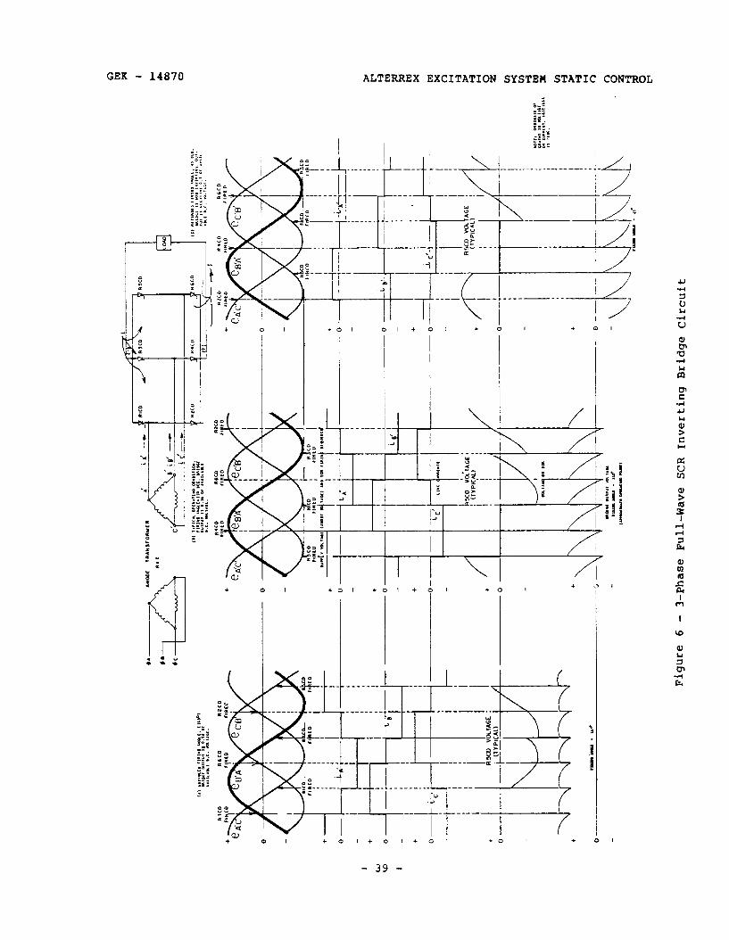
I :
8 i
’ I
I i
1 +
R5a
l V
OLT
AG
E f
/j
+ 1
0’
, (T
YP
ICA
L)
-O--
~-
+ 0 -
----
I l o-
-
+ -o--
-
/
\
1 \~
-
1
+ *
\
-u-Id
0
\ _;
-
____
_
=I--
_L
b’
- _
__~~
___
-&j_
__ I
’ I 1
i- I L
I
q-=
i ,,_
; -
I I
Lg)
-
h i .
x0
“c
x,AG
E
/ (‘y
p’c:
LL’ 7 \
\ + 0
-- --.
- c -c
Fi
gure
6
- 3-
Phas
e Fu
ll-W
ave
SCR
Inve
rtin
g Br
idge
Ci
rcui
t

ALTERREX EXCITATION SYSTEM STATIC CONTROL GEK - 14870
PRINCIPLES OF OPERATION (Continued)
operating condition is illustrated by Figure 6(b).
The top waveforms illustrate the source voltage and SCR firing sequence. The center waveforms indicate line current and current in the various SCRs.
The SCRs act as switches to connect the two output buses (positive and negative) to the three source lines sequentially as shown. The voltage subscripts indicate the voltage of the first line, with respect to the second line. Thus, in the graph Of eA'C'r line A' iS higher in potential than line C' wherever this graph is positive.
The phase sequence and choice of subscripts are consistent and show that line A' takes over conduction from line C', line B' takes over from line A', and line C' takes over conduction from line B'. The 'anode" voltage reference for RlCD then is eC'A'r which iS minus eA'C'- The anode voltage reference for R2CD is eAlC" The 'anode' voltage reference for R3CD is eAlBl ('eBIAI). The anode voltage reference for R4CD is eBlA'. The .anode" voltage reference for RSCD is eBcCl (-eClBl). The anode voltage reference for R6CD is eCaBl. The word anode is in quotation marks above in reference to RlCD, R3CD, and RSCD because these are the negative bus SCRs and their AC supply voltage connects to the cathode instead of the anode. Therefore, technically, it would be correct to call the supply voltage the cathode voltage and the supply voltage transformer the cathode transformer instead of anode voltage and anode transformer.
The net DC output voltage is then a plot of the difference in Voltage between the positive and negative buses, as indicated by the bottom waveforms. This is the voltage that would be seen on an OSCillOSCOPe connected standing on the negative bus looking at positive bus. The center waveforms indicate instantaneous current as it flows from an AC line, through a positive bus SCR through the load (DC), back through a negative bus SCR, to another AC line. The current is constant between commutation intervals because the inductance of the load (the exciter field winding) will not allow current to change appreciably during an SCRs conducting interval.
If the AC (or DC) regulator error signal calls for more excitation, the firing angle of all SCRs will advance, to furnish a higher (more positive) DC output voltage. See Figure 6(a). If the AC or DC regulator error signal calls for less excitation, the firing angle of all SCRs will retard, to furnish less positive DC output Voltage or even negative DC output voltage. See Figure 6(c).
For retarded firing angles the inductance of the load (exciter field winding) will force the instantaneous output voltage to follow the connected source voltage negative until the next SCR fires to connect
- 40 -
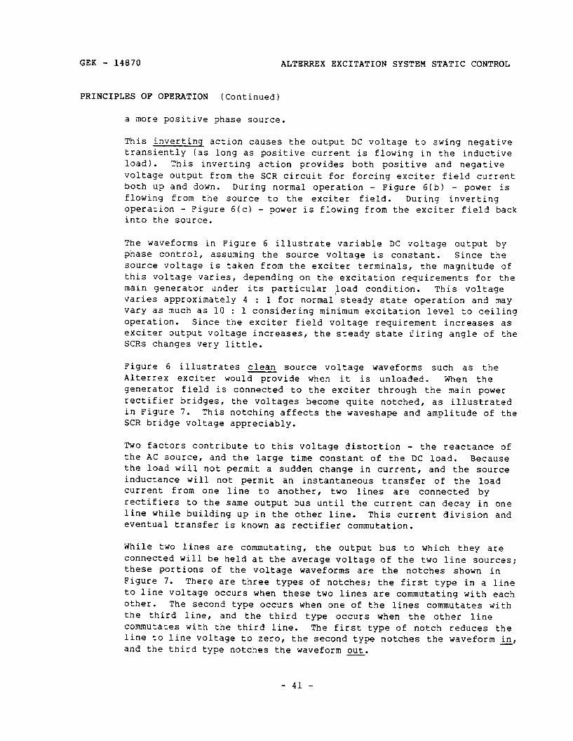
GEK - 14870 ALTERREX EXCITATION SYSTEM STATIC CONTROL
PRINCIPLES OF OPERATION (Continued)
a more positive phase source.
This inverting action causes the output DC voltage to swing negative transiently (as long as positive current is flowing in the inductive load). This inverting action provides both positive and negative voltage output from the SCR circuit for forcing exciter field current both up and down. During normal operation - Figure 6(b) - power is flowing from the source to the exciter field. During inverting operation - Figure 6(c) - power is flowing from the exciter field back into the source.
The waveforms in Figure 6 illustrate variable DC voltage output by phase control, assuming the source voltage is constant. Since the source voltage is taken from the exciter terminals, the magnitude of this voltage varies, depending on the excitation requirements for the main generator under its particular load condition. This voltage varies approximately 4 : 1 for normal steady state operation and may vary as much as 10 : 1 considering minimum excitation level to ceiling operation. Since the exciter field voltage requirement increases as exciter output voltage increases, the steady state firing angle of the SCRs changes very little.
Figure 6 illustrates clean source voltage waveforms such as the Alterrex exciter would provide when it is unloaded. When the generator field is connected to the exciter through the main power rectifier bridges, the voltages become quite notched, as illustrated in Figure 7. This notching affects the waveshape and amplitude of the SCR bridge voltage appreciably.
Two factors contribute to this voltage distortion - the reactance of the AC source, and the large time constant of the DC load. Because the load will not permit a sudden change in current, and the source inductance will not permit an instantaneous transfer of the load current from one line to another, two lines are connected by rectifiers to the same output bus until the current can decay in one line while building up in the other line. This current division and eventual transfer is known as rectifier commutation.
While two lines are commutating, the output bus to which they are connected will be held at the average voltage of the two line sources: these portions of the voltage waveforms are the notches shown in Figure 7. There are three types of notches: the first type in a line to line voltage occurs when these two lines are commutating with each other. The second type occurs when one of the lines commutates with the third line, and the third type occurs when the other line commutates with the third line. The first type of notch reduces the line to line voltage to zero, the second type notches the waveform &, and the third type notches the waveform out.
- 41 -
ALTERREX EXCITATION SYSTEM STATIC CONTROL GEK - 14870
I 17 :JYrlJzg:_-__,-___; / I ! I’ I L7
GEK - 14870 ALTERREX EXCITATION SYSTEM STATIC CONTROL
PRINCIPLES OF OPERATION (Continued)
Practically all of the source reactance is internal to the exciter so that the generated (clean) AC voltage is not available anywhere in the system.
Each SCR has an indicating neon light or two LEDs connected between its anode and cathode. Normally, the two electrodes of the bulb on the two LEDs should glow with unequal brightness. Should an SCR short and/or its fuse blow, the associated light(s) will go out. If an SCR fails to fire, both electrodes of its associated bulb will glow with almost equal intensity or both LEDs will be equally bright. When the firing angle is advanced, the electrode of the neon bulb connected to the SCR anode will glow brighter than the other electrode, or the red (or yellow) LED will be bright. When the firing angle is retarded, the electrode of the neon bulb connected to the cathode of the SCR will glow brighter, or the green LED will be brighter. The brightness also increases as exciter terminal voltage increases. This applies to an SCR bridge in service when the other bridge is removed from service. With both bridges in service, a non-firing SCR will not be detectable by its neon light or LED indicator - only a blown fuse will be detectable (it is assumed that if an SCR shorts out, its ruse will blow when both bridges are in service).
There is an RC circuit across each phase (line to line) of source voltage. This RC filter absorbs or furnishes current sufficient to prevent damaging voltage transients from occurring during SCR commutation.
b. Phase Control Circuit
The SCRs use a saturable reactor type firing and phase control circuit. This circuit is illustrated in Figure 8, which describes the firing of RZCD. Firing for all six SCRs is identical but occurs at different times (Figure 6 or Figure 7). Referring to Figure 6, it is necessary to vary the firing angle of the SCRs a full 180”, to provide maximum positive to maximum negative voltage. For RZCD, the voltage of A’ with respect to C’ varies from zero to a positive maximum to zero in this interval. This voltage is used to generate the applied voltage waveform shown in Figure 8, e ‘AC’ Thus, the voltage, e’ACf used as the supply voltage for firing R2CD, is exactly in phase with eA’C’_ (The same supply voltage is also used for firing RlCD, but 180" out of phase - accomplished by utilizing an identical winding on the supply transformer, but connected into its firing circuit in reverse polarity.)
The generation of the supply voltage, e’AC[ is explained later. It is essentially a square wave. This square wave is applied to R2SX, RJ’ and RX in series. The rectifier holds off e IAC (prevents current flow) during the negative half cycle, during which time the
- 43 -

Numbers in parentheses indicate points of time (2) and relate voltage across the firing reactor, eX, Figure 8 (top waveform) and flux in its core, Figure 8, (bottom B-H graphs). At the beginning of the cycle, the firing reactor, RZSX, is unsaturated (1); thus, its impedance is high and it allows only exciting current to flow in the resistors. This condition continues during (2) while the reactor is accumulating volt-seconds and its flux density, B, is increasing. At point (3), the reactor will saturate so that its impedance will drop sharply and cause most of the supply voltage to appear across the resist ors. The core material is a square loop type, so that the rising voltage across the series resistors, ef, is quite steep.
The vo ltage across RK would rise to a level given by:
GEK - 14870 ALTERREX EXCITATION SYSTEM STATIC CONTROL
PRINCIPLES OF OPERATION (Continued)
firing pulse for RlCD is generated.
R
ef x K
RJ + RK ’ but this increasing voltage across
RK will cause the silicon unilateral switch (SUS) to conduct at approximately 8 volts to apply the voltage of RK to the SCR gate circuit, e g* This voltage level is immediately clamped to 1-4 volts as RZCD fires. The voltage level is a characteristic of the SCR gate P-N junction. A Zener diode and a resistor are connected between the gate and cathode of each SCR as a back up feature to protect the SCR gate from excessive voltage. When the SUS fires, current flows through the gate to cathode junction of the SCR. Since its anode is positive with respect to its cathode at this time, the SCR fires and allows current to flow through its anode through gate to cathode. The SCR is essentially the semiconductor equivalent of a thyratron tube. Once the SCR is fired, anode current will continue until it decays to zero or is commutated to another path, after which the SCR must be refired before it will conduct again. The SUS is similar to an SCR except that it is self firing at a set anode voltage - in this case, 7.5 to 9 volts. Once the SUS has fired (an SUS is the semiconductor equivalent of a gas diode), its forward voltage drop is similar to a silicon rectifier - approximately one volt (es minus eg is approximately one volt). The SUS sets the voltage level where the SCR gate current begins, independent of the SCR anode characteristic or its gate resistance. It also prevents smaller voltages, such as noise, or the voltage due to R2SX exciting current, from firing the SCR. A capacitor is connected in parallel with RK to shunt any high frequency noise in the firing circuit and also to provide a low impedance gate current source when the SUS conducts.
The above description explains the SCR firing (1) - (2) - (3) in Figure 8. After the SCR is fired, there is no change until (4) when
- 44 -

I R
ZCD
4 ln
I
POSl
TlVL
B
US
!
e9
1 S
.U.S
. ,.I
- 9v
-f- C
l”,.‘
es
--
AD
VA
NC
ED
FI
RIN
G
AtJ
6I.E
Figu
r ‘e
8
- SC
R F
iring
A
nd
Phas
e C
ontro
l C
ircui
t
AR
US
ef
- e&
-e,
(p05
1~10
N
HA
LF
OF
&c
ON
LY)
RE
TAR
DE
D
FIR
M
AN
GLE
e
THE
TH
RE
E V
OLT
AG
E
LEV
ELS
S
HO
WN
H
ER
E
EN
= C
j(rrr
rj
* &
E.
= F,
IIW~
VO
LTA
&C
OF
su.s
.
E,=
t*
TE
P-Y
,u
acT,
0”
VOLT
AOL
1.
Ii 0
FLU
X
IN
4 S
ATU
RA
BLE
R
EA
CTO
R
J
CO
RE
C
d
1 J

ALTERREX EXCITATION SYSTEM STATIC CONTROL GEK - 14870
PRINCIPLES OF OPERATION (Continued)
the supply voltage, eAC swings negative, and the rectifier then holds off the supply voltage, preventing reverse current in the gate winding of R2SX. The flux then returns to the Br point. The regulator output applies a voltage to the control winding of R2SX that causes exciting current to flow to produce a flux in the opposite direction from that resulting from the gate winding current, so the reactor begins accumulating volt-seconds on the opposite side of the B-H loop, (5). At the end of the negative half-cycle (11, the exciting current again transfers back to the gate winding, which begins accumulating positive volt-seconds (2).
The volt-seconds that must be accumulated before R2SX again saturates at (3) is determined by how much the flux was driven down the B-B loop (reset) during the previous negative half-cycle - (5). If the regulator output (reset voltage) is small during the negative half-cycle, the flux will not be pushed far down the B-H loop so few volt-seconds need be accumulated during the next positive half-cycle before RZSX will saturate. This is illustrated by the left graphs of Figure 8. If the regulator output (reset voltage) is large during the negative half-cycle, the flux will be pushed far down the B-H loop, so more volt-seconds will need to be accumulated during the next positive half-cycle before RZSX will saturate. This is illustrated in the graphs on the right side of Figure 8.
Note in Figure 8 that for a positive half-cycle of R2SX voltage, e,, the area of the shaded portion (volt-seconds) must be equal to the preceding negative half-cycle volt-seconds. Thus, as regulator output increases, the firing angle is retarded, and the output voltage from the SCR circuit decreases.
The waveforms described above will be subject to distortion, when the exciter is loaded, because the generating waveforms (exciter terminal voltage) are distorted. The major effect is that a period of dwell (at zero volts) is introduced in the E'AC, and all subsequent waveforms, at the instant of sign reversal.
The above description and Figure 8 illustrate firing of R2CD. The firing circuits for all other SCRs are identical. The regulator output (reset) is applied to all six firing reactors in parallel (RlSX through RZSX) so that all six SCRs in each rectifier bridge are firing at the same respective angle, thus achieving balanced firing.
The SCR firing circuit for each SCR rectifier bridge is brought out through the rectifier disconnect switch, RlSW (of RZSW). (See Figure 9.1 This firing circuit requires three points: 0 volts (common), -22VDC (or -24VDC), and a variable control voltage, 0 to -24VDC. The control voltage range is limited from 0 to -1lVDC on units with a de-excitation circuit. The common point is always connected to both
- 46 -
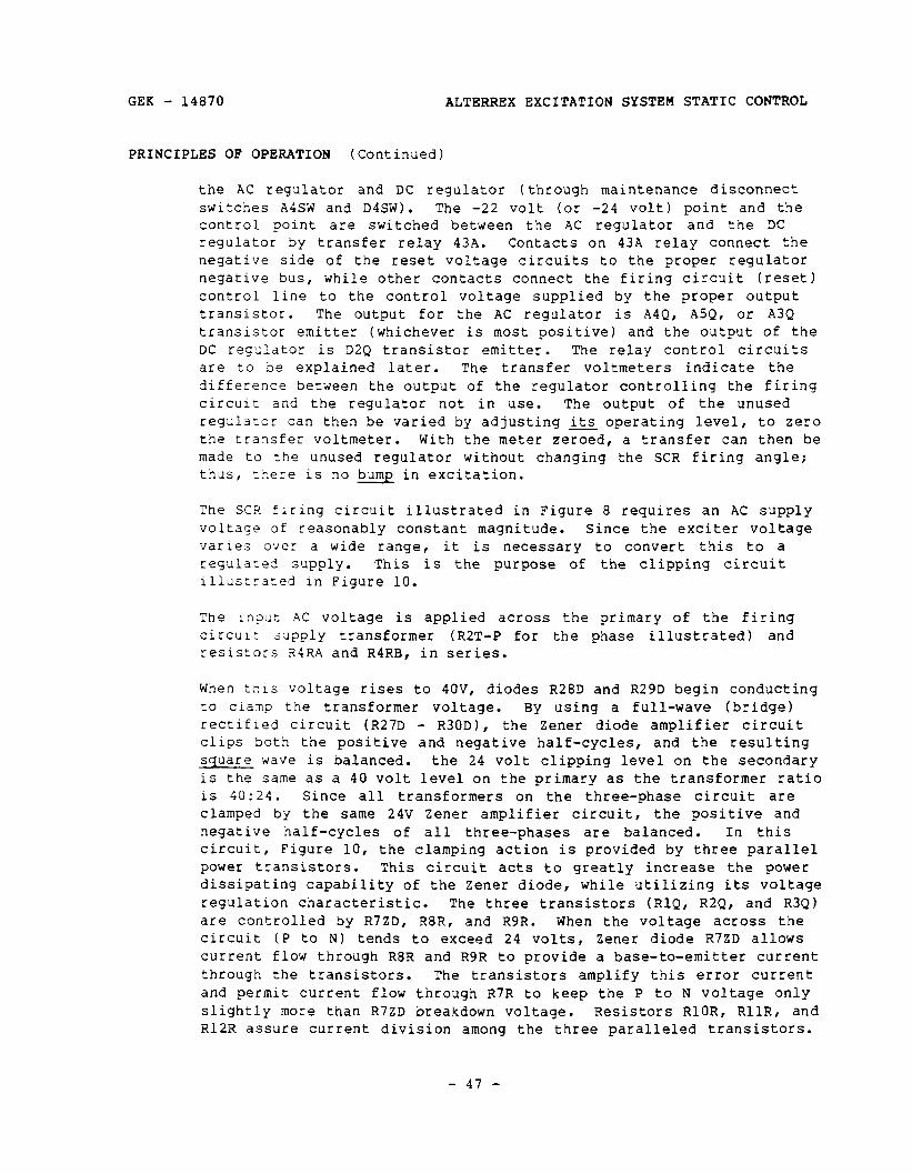
GEK - 14870 ALTERREX EXCITATION SYSTEM STATIC CONTROL
PRINCIPLES OF OPERATION (Continued)
the AC regulator and DC regulator (through maintenance disconnect switches A4SW and D4SW). The -22 volt (or -24 volt) point and the control point are switched between the AC regulator and the DC regulator by transfer relay 43A. Contacts on 43A relay connect the negative side of the reset voltage circuits to the proper regulator negative bus, while other contacts connect the firing circuit (reset) control line to the control voltage supplied by the proper output transistor. The output for the AC regulator is A4Q, ASQ, or A3Q transistor emitter (whichever is most positive) and the output of the DC regulator is D2Q transistor emitter. The relay control circuits are to be explained later. The transfer voltmeters indicate the difference between the output of the regulator controlling the firing circuit and the regulator not in use. The output of the unused regulator can then be varied by adjusting its operating level, to zero the transfer voltmeter. With the meter zeroed, a transfer can then be made to the unused regulator without changing the SCR firing angle: thus, there is no bump in excitation.
The SCR firing circuit illustrated in Figure 8 requires an AC supply voltage of reasonably constant magnitude. Since the exciter voltage varies o%ier a wide range, it is necessary to convert this to a regulated supply. This is the purpose of the clipping circuit illustrated in Figure 10.
The input AC voltage is applied across the primary of the firing circuit supply transformer (R2T-P for the phase illustrated) and resistors R4RA and R4RB, in series.
When tn~s voltage rises to 4OV, diodes R28D and R29D begin conducting to clamp the transformer voltage. By using a full-wave (bridge) rectified circuit (R27D - R30D), the Zener diode amplifier circuit clips both the positive and negative half-cycles, and the resulting square iJave is balanced. the 24 volt clipping level on the secondary is the same as a 40 volt level on the primary as the transformer ratio is 40:24. Since all transformers on the three-phase circuit are clamped by the same 24V Zener amplifier circuit, the positive and negative half-cycles of all three-phases are balanced. In this circuit, Figure 10, the clamping action is provided by three parallel power transistors. This circuit acts to greatly increase the power dissipating capability of the Zener diode, while utilizing its voltage regulation characteristic. The three transistors (RlQ, R2Q, and R3Q) are controlled by R7ZD, R8R, and R9R. When the voltage across the circuit (P to N) tends to exceed 24 volts, Zener diode R7ZD allows current flow through R8R and R9R to provide a base-to-emitter current through the transistors. The transistors amplify this error current and permit current flow through R7R to keep the P to N voltage only slightly more than R7ZD breakdown voltage. Resistors RlOR, RllR, and R12R assure current division among the three paralleled transistors.
- 47 -
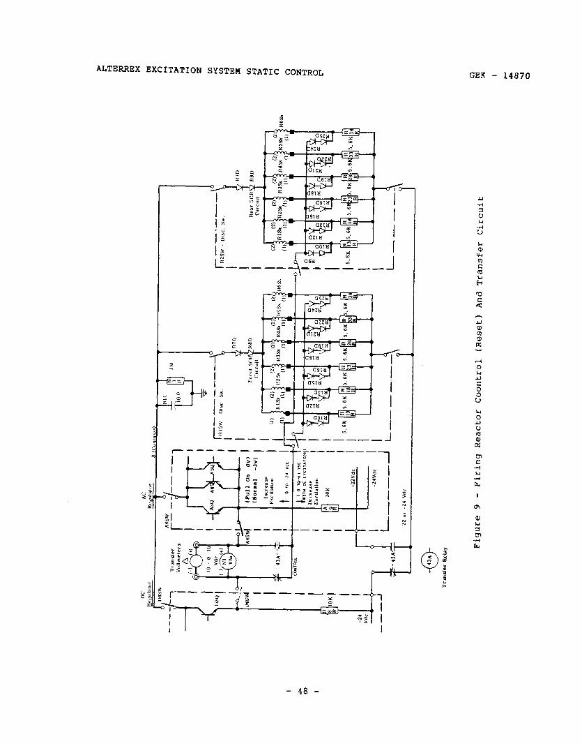
ALTERREX EXCITATION SYSTEM STATIC CONTROL GER - 14870
I
- 48 -
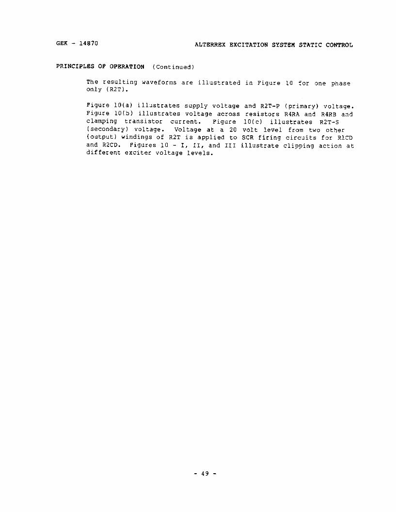
GEK - 14870 ALTERREX EXCITATION SYSTEM STATIC CONTROL
PRINCIPLES OF OPERATION (Continued)
The resulting waveforms are illustrated in Figure 10 for one phase only (R2T).
Figure 10(a) illustrates supply voltage and RZT-P (primary) voltage. Figure 10(b) illustrates voltage across resistors RIRA and RIRB and clamping transistor current. Figure 10(c) illustrates R2T-S (secondary) voltage. Voltage at a 20 volt level from two other (output) windings of R2T is applied to SCR firing circuits for RlCD and R2CD. Figures 10 - I, II, and III illustrate clipping action at different exciter voltage levels.
- 49 -
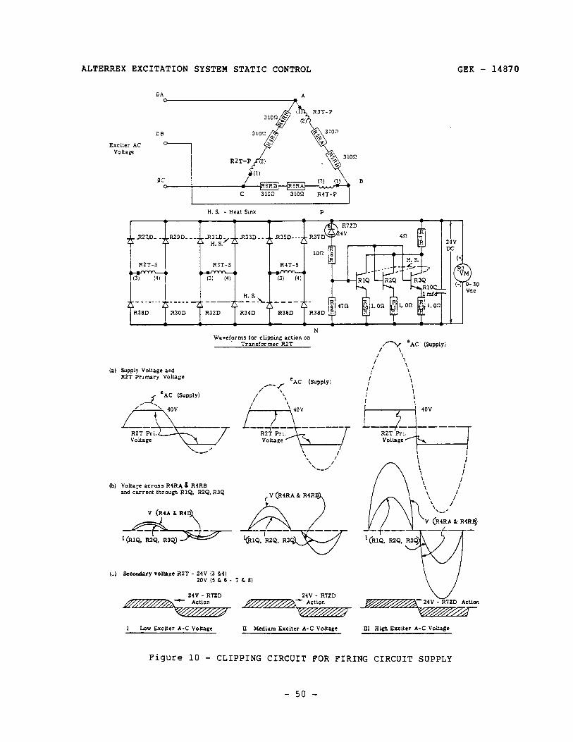
ALTERREX EXCITATION SYSTEM STATIC CONTROL GEK - 14870
Exciter AC V0lta.ge
H. S - Heat Smk P
RZZO_ _ R29D___ R3Lb_ 2s H.S.’
R33D_. R35D--- I 24v DC
eAc 6uPPlY) I
/ \ \
I \
/
\ \
: \ \
: 1 I
n-I’“’
(a) Supply Voltage and R2T Prrmary Voltage
\ \ I \ \ /I
‘_.’
IV (R4RA & RQRBA
(b) Volt&y xross R4RA 6 R4RB and current through RIQ. R2Q. R3Q
(;I Secondary voltage RZT - 24V (3 L4) zov (5 L 6 - 7 & 8)
24V - R’IZD 24V - RIZD
I Low Exciter A-C vo!uge II Medium Exciter A-C Voltage III High Exciter A-C Volta+
Figure 10 - CLIPPING CIRCUIT FOR FIRING CIRCUIT SUPPLY
- 50 -
GEK - 14870 ALTERREX EXCITATION SYSTEM STATIC CONTROL
PRINCIPLES OF OPERATION (Continued)
2. Diode Rectifier Circuit
a. Current Boost
Current boost is provided in order to prevent collapse of the excitation system after suddenly applied system faults, sudden generator reactive load pickup, and generator load rejection. Exciter field power is normally taken from the exciter output terminals: however, exciter field current must be maintained even when exciter terminal voltage drops very low.
Although the probability of the occurrence of faults, sudden reactive load pickup, or sudden load rejection may be exceedingly low for an individual generator, the very possibility of their occurrence is sufficient to justify inclusion of the current boost feature in the excitation system. So, this circuitry which will probably never be used during the life of the equipment is simple in design, rugged in construction, very conservatively rated, and requires no maintenance. These features greatly enhance the reliability of the system.
Figure 11 is a diagram illustrating the relationship between exciter field current and exciter line current for two conditions. One of these conditions is steady state load represented by the generator field supplied through the main field rectifier from the exciter terminals. The other is a short-circuit on the exciter output lines. There are, of course, an infinite number of possible load conditions that would fall between the two shown in Figure 11.
Current transformers in the exciter output lines supply current to the current boost diode bridge. The ratio of these transformers is selected such that for any point (such as point A) on the steady-state load curve of Figure 11, the current supplied to the current boost bridge COD) is less than the field current required (OF) to supply the exciter line current (OE).
The current transformer ratio is such that in addition to meeting the requirement just described, the current supplied under the short circuit condition for the same exciter line current to the current boost bridge (OD) is more than the field current required (OG) to supply the exciter line current (OE).
Thus, for steady-state load conditions, the current boost feedback at any particular line current is less than the field current required to produce that line current. In this case, however, there is exciter line voltage with the result that the SCR bridge is in control and supplies the required field current which flows through the current boost diodes and on into the exciter field. The current boost current also flows in the current boost bridge. Since current boost current
- 51 -
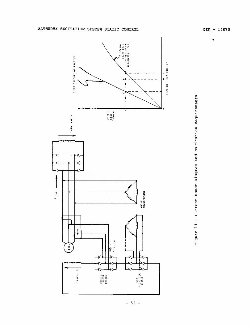
Itxc.
r:Il.
f
C”R
fltK
i 8
BO
OS
1 HR
IDGE
c 1
SC
M
RfC
lI~IC
R
Bfi
IDCE
a-
I LI
NE
AN
OD
E
TRA
NS
FOR
YE
R
1 ’ C
EN
. f
IELD
fXC
IIEll
LINE
CU
RREN
T
CCNC
AATO
H f
ILL”
0 c
D
F
Figu
re
11 -
Cur
rent
Bo
ost
Dia
gram
A
nd
Exci
tatio
n R
equi
rem
ents
GEK - 14870 ALTERREX EXCITATION SYSTEM STATIC CONTROL
PRINCIPLES OF OPERATION (Continued)
is less than field current, the extra field current supplied from the SCRs flows across the current boost diode bridge. All six diodes in the current boost bridge are conducting continuously - the current transformer secondary line current modulates the steady exciter field current, divided among the three legs. Under this steady-state load condition, the voltage across the bridge is only the forward drop of two diodes in series. The SCR bridge has control and is almost totally unaffected by the presence of the current boost bridge in the circuit.
For the short-circuit load condition, the current boost feedback at any particular line current is more than the field current required to produce that line current. During a short-circuit condition, voltage to the SCR bridge is zero; thus, its output voltage is zero, but the last SCRs to be conducting prior to the application of the short- circuit *rill continue to conduct. Because of the fact that current boost under the short-circuit condition is regenerative, and since an SCR patn remains conducting, exciter field current will build up until the carrent transformers saturate. The transformers are designed so that at :ne point of saturation, the current boost circuit will be supplying the necessary exciter field current to maintain rated exciter line current.
It is also obvious that, depending on the actual ratio selected for the current boost current transformers, the boost circuit will take over control of the field, and maintain excitation for transient load conditions considerably less extreme than a continuous short-circuit.
The current boost CT construction is described in the INSTALLATION section of this book.
Like any CT, the current boost CT can be damaged by high voltage if it is prevented from transforming current from a high power, low impedance source to a lower power or signal circuit.
Lens's law, e = Nd@/dt, applies to a CT as to any other transformer.
In the usual CT low-current circuit, the impedance is very low, and often can be considered a short-circuit. Then the voltage is practically zero. Thus, d@/dt is zero. This requires that the net flux, $3, be zero. To achieve this, the secondary mmf, N2i2, must be equal and opposite to the primary mmf, Nlil; the result,
i2 = (Nl/N2)i1, is the functional equation of a current transformer.
The current boost CT has two modes of operation.
- 53 -

ALTERREX EXCITATION SYSTEM STATIC CONTROL GEK - 14870
PRINCIPLES OF OPERATION (Continued)
(1) Normal operation: Exciter field current exceeds the peak current fed back to the current boost bridge. Therefore, the feedback current circulates within the bridge and does not get out. The current in each of the six diodes is positive, non-zero at all times, modulated by the CT feedback current. The only voltage from line-to-line is the difference in the forward voltage drop of identical rectifier cells. This is negligibly small. Since the voltage across the secondary winding is very small, and the trimmer winding is wound on the same core, by Lens's law, its voltage will be much lower, as it consists of a fraction of the turns and it is linked by the same flux.
(2) Current boost operation: This occurs only when the induced generator field current exceeds the exciter line current to the generator field rectifiers. This causes free-wheeling of these rectifier bridges, resulting in a virtual short-circuit at the rectifier AC terminals. In this situation the SCR anode voltage is zero; firing pulses cease to be generated: the last-fired positive bus SCR and the last fired negative bus SCR remain conducting: exciter field current now contains an induced component resulting from the suddenly appli.ed virtual three-phase short-circuit; the total exciter field current decays rapidly. When the peak CT feedback current exceeds the total exciter field current, the current pops out of the current boost rectifier bridge to hold excitation up. As long as free-wheeling exists, the exciter field voltage will be limited by the flux- saturation of the current boost CTs. This is designed (and tested) to be that required to supply 1.0 per-unit exciter line current to the virtual short-circuit at the generator field rectifiers. Again, by Lens's law, the voltage induced in the trimmer winding of the CT will be a fraction of the voltage in the secondary winding, which is core-design and circuit resistance limited. Current boost action builds up and then maintains the exciter line current to the free- wheeling generator field rectifier bridges at the 1.0 per-unit level. when this current exceeds the decaying induced generator field current, the current maintained in the exciter field converts the internal drop to terminal voltage. This provides firing power and anode voltage to the SCRs and the SCR bridge then takes over from the current boost bridge.
The point to be emphasized here is that the CTs are never unloaded: they are either shorted or loaded by the exciter field. Therefore, dangerously high voltages, due to the inability of the secondary circuit to establish mmf in opposition to the primary mmf, will not be developed on the open trimmer windings.
- 54 -
GEK - 14870 ALTERREX EXCITATION SYSTEM STATIC CONTROL
PRINCIPLES OF OPERATION (Continued)
I I---
1
L CA”T’oN I-m- J
THESE WINDINGS MUST NOT BE SHORTED, CURRENT BALANCE WILL RESULT. THIS DUE TO EXCESSIVE 12R HEATING: AT
AS AN INDETERMINATE MAY DESTROY THE CT ANY EVENT, CURRENT
BOOST WILL BE PREVENTED, ALLOWING EXCITATION TO COLLAPSE DURING GENERATOR FAULTS OR SUDDEN LOADING.
b. Static Switch
Some exciter types do not have the large separation between the two excitation curves shown in Figure 11. Thus, it is not possible to design current transformers with a ratio low enough to ensure that the current boost circuit will be regenerative under short-circuit and yet with a ratio high enough so that the current fed back will not interfere with the exciter field current supplied by the SCR bridge, unoer normal operating conditions.
A static switch has been developed to ensure compatibility between the SCR bridge and the diode bridge under normal operation, and yet permit the current feedback to be sufficient to support an exciter short- circuit, regardless of the separation between the two excitation curves for the exciter. This is illustrated in Figure 12.
The major components of the static switch are three SCRs, connected in shunt in reverse polarity with each negative-bus diode (R4D, R5D, and R6D) of the current boost bridge.
These SCRs are continuously gated, or turned on, when the exciter voltage exceeds 45V, rms, line-to-line. Whenever the exciter voltage drops below 45V, the SCRs are ungated, which effectively eliminates them from the current boost circuit, allowing the current boost bridge to develop an output voltage.
With the SCRs gated, they and the negative-bus diodes provide a circulating path for feedback current of whatever magnitude from the current boost CTs.
The gating circuit for the static switch takes its power from the exciter terminals. Exciter voltage is supplied through current- limiting reactors RSlX, RS2X, and RS3X to saturating transformers RSlST, RS2ST, and RS3ST. The output voltage of the saturating transformers is rectified and filtered by rectifiers RSlD - RS6D, choke RS4X, and resistor RSlR. The resulting DC is applied to the gates of SCRs RSlCD, RS2CD, and RS3CD through individual gate
- 55 -
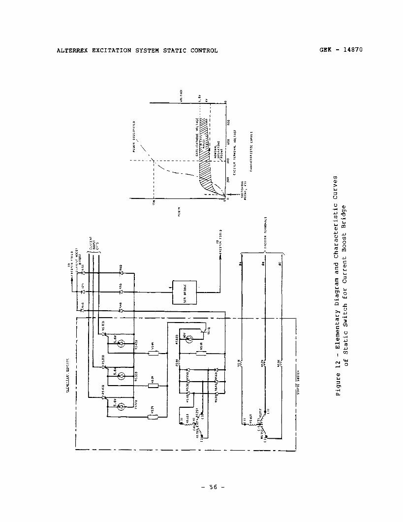
I ul m
I
(1
I
Figu
re
12
- El
emen
tary
D
iagr
am
and
Cha
ract
eris
tic
Cur
ves
of
Stat
ic
Switc
h fo
r C
urre
nt
Boos
t Br
idge
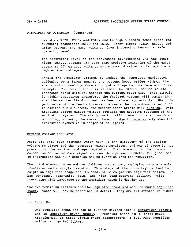
GEK - 14870 ALTERREX
PRINCIPLES OF OPERATION ( Continued)
resistors RSZR, RS3R, and RSIR, and
EXCITATION SYSTEM STATIC CONTROL
through a common Zener diode and switching transistor RSlZD and RSlQ. Zener diodes RS2ZD, RS3ZD, and RS4ZD prevent the gate voltages from increasing beyond a safe operating level.
The saturating level of the saturating transformers and the Zener diode, RSlZD, voltage are such that positive switching of the gates occurs at 45V exciter voltage, while power dissipation is kept low at high exciter voltages.
Should the regulator suddenly, by a large
attempt to reduce the generator excitation amount, the current boost bridge without the
static switch would produce an output voltage to interfere with this attempt. The reason for this is that the current source is the generator field circuit, through the current boost CTs. This circuit is highly inductive: therefore, the feedback current will remain high when the exciter field current has been reduced appreciably. When the peak value of the feedback current exceeds the instantaneous value of th exciter field current, the current boost bridge will turn on. This transient bridge output voltage degrades the negative response of the excitation system. The static switch will prevent this action from occurring, allowing the current boost bridge to turn on only when the excitation system is in danger of collapsing.
EXCITER VOLTAGE REGULATOR
There are only four elements which make up the circuitry of the exciter voltage regulator and the generator voltage regulator, and one of these is not present in the exciter voltage regulator. That element is the common connection of two or more signal sources through semiconductor P-N junctions to incorporate the ‘OR’ decision-making function into the regulator.
The third element is an emitter follower connection, employing only a single transistor and a single resistor. This stage of the circuitry is used to couple an amplifier stage and its load , or to couple two amplifier stages. It has constant, near-unity gain, and high load-carrying ability, while presenting high impedance to the amplifier which is driving it.
The two remaining elements are the regulator front end and the basic amplifier stage. These will now be described in detail - they are illustrated in Figure 13.
1. Front End
The regulator front end can be further divided into a comparison circuit and an amplifier power supply. Preceding these is a three-phase transformer, or three single-phase transformers, a full-wave rectifier bridge, and an R-C filter.
- 57 -

ALTERREX EXCITATION SYSTEM STATIC CONTROL GEK - 14870
PRINCIPLES OF OPERATION (Continued)
The transformer(s) provide circuit separation or isolation, and step voltage either up or down to achieve the desired level for the remaining circuits. The three-phase full-wave rectification and the filter, whose time constant is matched to the AC supply frequency, then convert the signal source to a direct (unidirectional) voltage whose amplitude is proportional to the magnitude of the AC signal source voltage.
a. Comparison Circuit
The comparison circuit is merely a resistive voltage divider circuit. It is composed of fixed and ad justable resistors, one of which is a voltage-adjusting potentiometer. When the comparison circuit is connected across the direct voltage developed by the rectifier and filter, the voltage from the arm, slider, or wiper of the voltage- adjusting potentiometer to either end of the comparison circuit is then a fraction of the filter output voltage. The most important contributor to this fraction is the position of the arm of the potentiometer.
b. Amplifier Power Supply
The amplifier power supply is a Zener diode supplied with sufficient current to turn it on from the filter output voltage, through a voltage-dropping resistor.
The difference between the voltage at the arm of the potentiometer and the voltage at the Zener diode is often referred to as the error voltage. Classically, this usage implies that the error voltage is reduced to zero, in the steady-state, by a regulator which is functioning properly.
In this application, the difference voltage is not reduced to zero, but the proper functioning of the regulator will keep it constant. Therefore, this voltage difference will not be called the error voltage here, although it may be helpful in signal tracing and in troubleshooting to think of it this way.
2. Basic Amplifier Stage
The second part of Figure 13 illustrates the basic amplifier stage used in the regulators. It consists of two transistors and four or more resistors, of which one may be a rheostat or an adjustable resistor: the transistors are reverse polarity types - the input transistor in NPN, and the output transistor is PNP. The stage is collector-coupled and emitter-follower coupled. Consequently, it has the high gain characteristic of the former connection and the negative feedback stability of the latter connection. Ideally, its characteristic is that of a resistive voltage divider in reverse. This is illustrated by the approximate equation for the gain of
- 58 -
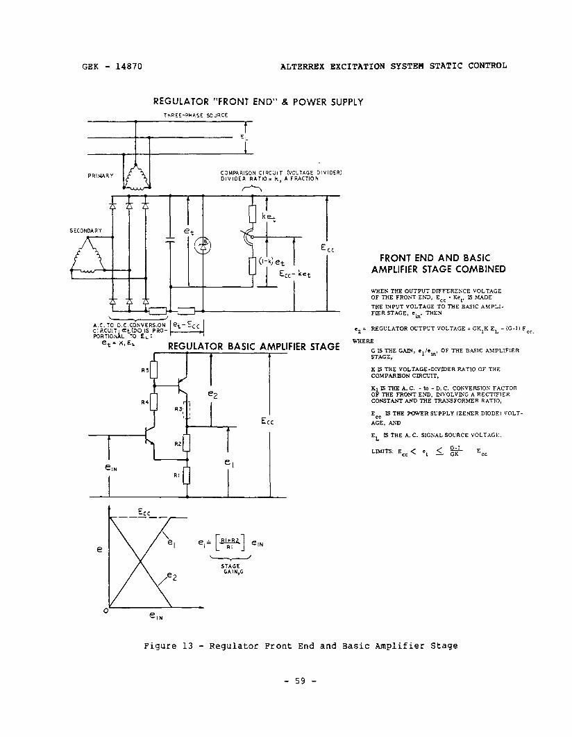
GEK - 14870 ALTERREX EXCITATION SYSTEM STATIC CONTROL
REGULATOR “FRONT END” & POWER SUPPLY THREE-PHASE SOURCE
PRIMARY
t_?i
CaUPAR!SON CIRCJIT VOLTAGE DIVIDER) DIVIDER RATIO. k, A FRACTION
A A
L t
k,et SECONDARY
%
A.C.T~ clRCClr.etDcl IS PORTIONAL TO E,:
PRO-
e,=K,EL - REGULATOR BASIC AMPLIFIER
e RI+RZ
elN e,+ c I RI
I ’ STAGE GA I N,G
e IN
C
FRONT END AND BASIC AMPLIFIER STAGE COMBINED
WHENTHEOUTPUTDIFFERENCE VOLTAGE OF THE FRONT ESD, E,, - Ket. Is MADE
THE INPUT VOLTAGE TO THE BASIC AMPLI- FIERSTAGE, ein. THEN
l 2 = REGULATOR OUTPUT VOLTAGE = GK7K EL - (C-1) Ecr,
WHERE
iT7SGS GAIN, elkin, OF THE DA..IC AhlPLlFER
K Is THE VOLTAGE-DIVIDER RAT70 OF THE COMPARISON CIRCLTIT,
K1lSTHEA.C. - to - D. C. CONVERSION FACTOR OF THE FRONT END, INVOLVMG A RECTIFIER CONSTANT AND THE TRANSFORMER RATIO,
E IS THE POWER SUPPLY (ZEXER DIODE) VOLT-
A%, AND
EL Ls THE A. C. SIGNAL SOURCE VOLTAGE.
LIMITS: Ecc < e, 1. ‘2 Ecc
Figure 13 - Regulator Front End and Basic Amplifier Stage
- 59 -
ALTERREX EXCITATION SYSTEM STATIC CONTROL GEK - 14870
PRINCIPLES OF OPERATION ( Continued 1
the stage given in Figure 13. The stage gain is relatively unaffected by changes in the current gain, alpha (or beta), of the individual transistors.
Finally, if the difference voltage from the regulator front end is made the input voltage to the regulator basic amplifier stage, and the power supply connected to the transistors, an overall regulator characteristic equation can be obtained. This is the final equation on Figure 13. In this equation:
Regulator Output Voltage = GKIKEL - (G - l)E,,, G is the gain, el/einr of the basic amplifier stage, K, is the voltage-divider ratio of the comparison circuit, Kl is the conversion factor for the front end AC voltage-to-DC voltage, involving a rectifier constant and the transformer ratio, EC, is the power supply (Zener diode) voltage, and EL is the AC signal source voltage.
Thus, for G, K, and Kl fixed, an increase in EL results in an increase in the regulator output voltage, and vice versa.
Equally important, if K and EL are made to vary in inverse proportion, the regulator output voltage will not change.
It was mentioned earlier that the exciter field excitation requirement is very nearly proportional to the exciter voltage, when the exciter load resistance is constant. Since the exciter load is the generator field and the main rectifiers, the equivalent load resistance seen by the Alterrex exciter is constant. (However, changes in field temperature cause variation in load resistance.) Then, since the gate clipping circuit supplies essentially constant source voltages to the SCR firing circuits, the firing angle will remain constant if the regulator output remains constant. When the firing angle of the SCRs is held constant, the ratio of DC voltage from the SCR bridge to AC voltage to the bridge is also constant.
Thus, a fundamental operating characteristic of this excitation system is a very nearly constant regulator output (firing reactor reset) voltage, in the steady-state.
In the exciter voltage regulator, K is controlled by the position of 7OP; EL is the exciter line voltage, and EL will rise to offset a decrease in K.
The remaining circuitry is a current source for auxiliary power, output diodes for free-wheeling of saturable reactor reset current should the regulator output voltage increase at an abnormally high rate, an output voltmeter, maintenance disconnect switches, fuses for exciter protection, and a dummy output load resistor. The dummy load resistance is approxi-
- 60 -
GEK - 14870 ALTERREX EXCITATION SYSTEM STATIC CONTROL
PRINCIPLES OF OPERATION (Continued)
mately equal to the equivalent resistance of the reset circuits of the firing reactors, twelve in parallel. (See Figure 9.)
The complete regulator is shown in Figure 14, along with typical operating voltages.
The current source is DC regulator CTs, whose primaries are in the AC lines from the current boost CT secondary delta to the current boost bridge. The secondaries of the DC regulator CTS are themselves connected in delta, and loaded by resistors across each secondary, as well as by the rectifier bridge in the exciter voltage regulator, Zener diode D2ZD (on older models ) , resistor DlR and power supply Zener diode DlZD. This CT loading converts current to voltage to make this source available for auxiliary regulator power. The DC regulator CTs saturate above generator no-load field current. The L-C filter and the 24V Zener eliminate ripple from the bridge.
Following a condition ( A ) when generator field voltage (exciter output voltage) increases, as may happen for sudden load changes on the generator, the junction of UllR, Ul2R and D~R will move down and the base of D3Q will move down. Also, the base of DlQ will move up and the emitter or D2Q will move down to decrease excitation.
Newer models have a de-excitation circuit as part of the equipment. contacts of an external miniature sealed relay connect the base of the PNP transistor DlQ to its emitter, causing the reset voltage, the regulator output voltage, to increase to about 1OV (set by D3ZD). This phases back the SCRs , inverting their output. This is accomplished when an excitation shutdown signal is sent to the equipment.
GENERATOR VOLTAGE REGULATOR
1. The front end of the generator voltage regulator is practically the same as the front end of the exciter voltage regulator. The principal differences are:
a. the inclusion of compensation voltages in one of the three AC signal source lines,
b. component design is influenced by the more limited range of variation of the AC signal voltage,
C. the comparison circuit is arranged differently, and
d. two power supplies are provided; one for the transistor amplifier circuitry, and one for the load - the reset circuits of the SCR firing reactors.
- 61 -
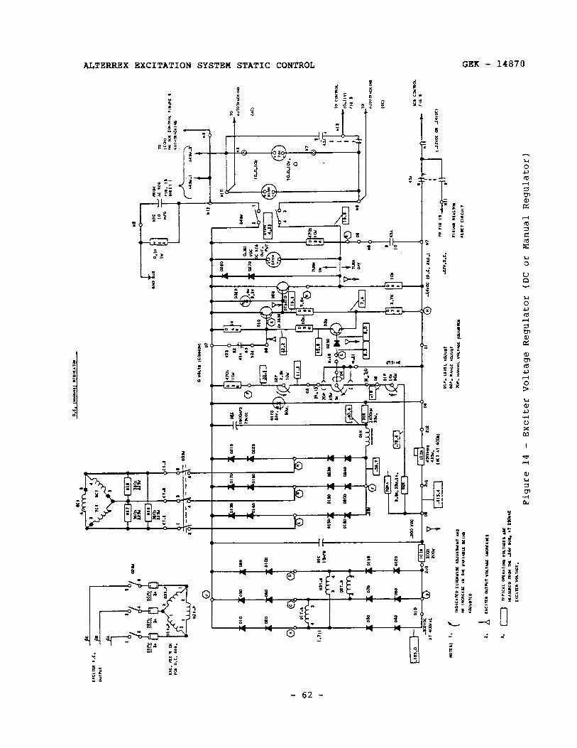
r--t
--k
Q
f t
I ’
Figu
re
14 -
Ex
cite
r Vo
ltag
e Re
gula
tor
(DC of
Ma
nual
Re
gula
tor)
GEK - 14870 ALTERREX EXCITATION SYSTEM
PRINCIPLES OF OPERATION (Continued)
2. The basic amplifier stage is the same, but two stages are one. These two stages are coupled by an emitter-follower
STATIC CONTROL
used instead of stage. Whereas
the gain of the amplifier stage of the exciter voltage regulator is fixed, the gain of each stage of the generator voltage regulator is adjustable.
This much comprises the major components of the regulator, which is shown in Figure 15(a). This figure also shows two of the auxiliary circuits and two 'OR" function connections for these auxiliary circuits.
Two amplifier stages are used because the generator voltage regulation accuracy required is quite high. Consequently, the regulator gain must by high. Because of the high regulator gain, and the nature of the closed loop transfer function of the exciter, generator, and regulator, exciter voltage rate stabilizing is required to make the system non-oscillatory.
Also, a ripple filter and an output filter are added to keep high frequency signals from being generated and transmitted within the regulator circuitry. These components are A24R, A25R, and A4C at points 10, 11, and 6 (Figure 151, and AllC at points 2 and 14.
- 63 -
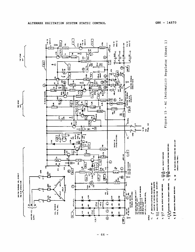
ILC
. “L
P*C
I
,a
AC
. “t
n.
I I
I I
. I
I c
it l-h
Figu
re 15
- A
C (A
utom
atic
) Re
gula
tor
(She
et 1)
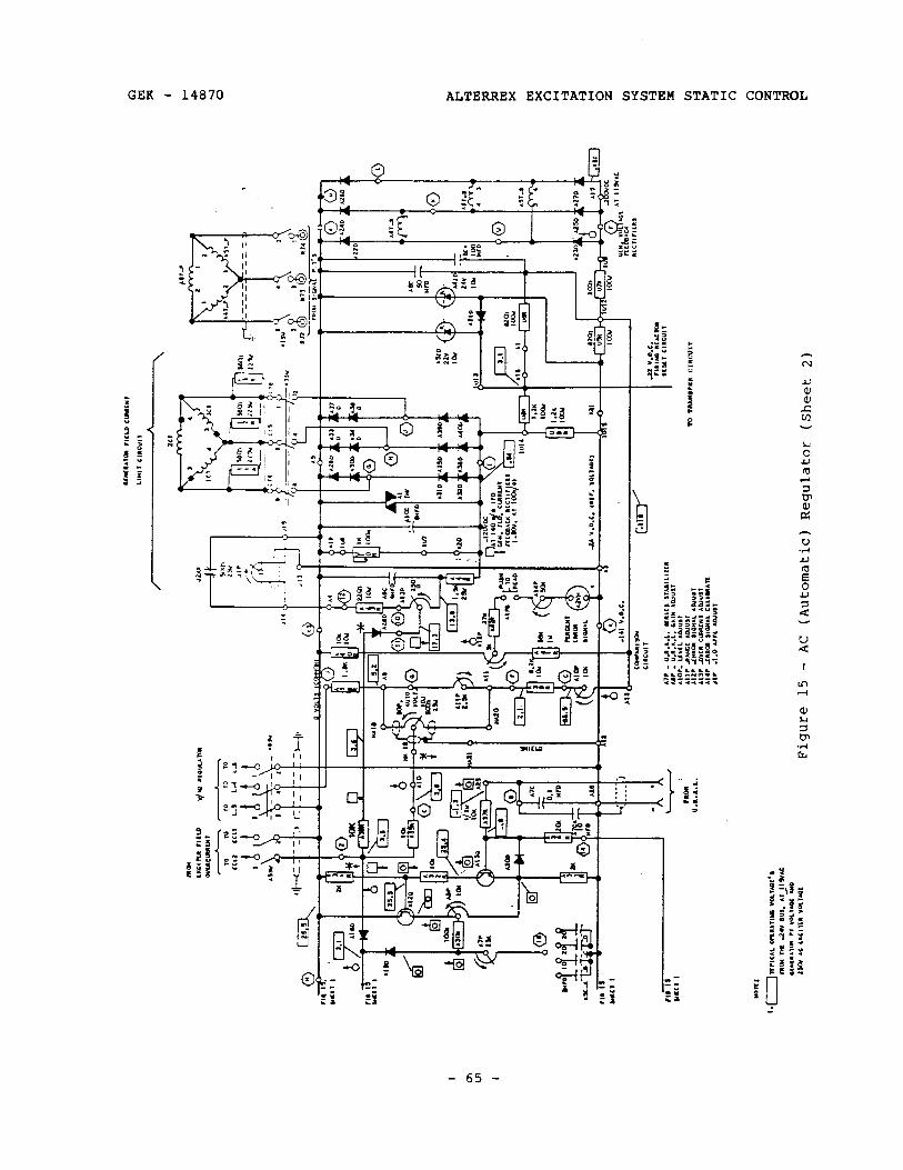
_J
Figu
re 15
- A
C (A
utom
atic
) Re
gula
tor
(She
et 2)
ALTERREX EXCITATION SYSTEM STATIC CONTROL GEK - 14870
PRINCIPLES OF OPERATION (Continued)
3. Auxiliary Circuits
The first auxiliary circuit added to the AC regulator is exciter feedback voltage. A direct voltage proportional to exciter voltage is developed across AlC. This voltage is now applied to the AC regulator in the following two ways.
a. Exciter Stabilizing
A signal voltage which varies with the exciter AC voltage as shown in the graph of Figure 16 is generated by components AlZD, U4R, A15R, Al4R, A17R, and A3ZD. This voltage is then introduced into the second stage amplifier of the AC regulator through components A4P, A2C, and A2lR. The emitter-base junction of transistor A8Q, resistor A20R, and rheostat A3P comprise the return path for this signal.
The sense of this signal variation is such as to oppose a change which created the variation. To illustrate this, a signal will be traced through the closed loop system of generator, regulator , exciter, generato;, etc.
Beginning with the symbol defined in note 2 of Figure 15, 6 , the arrow pointing in the direction of voltage signal change at a particular point in the circuit, generator terminal voltage drops. This may have occurred as a result of increased loading on the generator.
The anodes of A23D, A25D, and A27D will move up (less negative, or more positive). The comparison circuit connected to AlOP will move up* The wiper of 9OP will move up. The anode of A18D and base of AllQ will move up. The base of AlOQ will move down. The junction of A25R, A26R and A6P will move up and the base of A9Q will move Up. The base of A8Q will move up and the base of A7Q will move down. The base of A4Q and collector of A7Q will move up. The emitter of A4Q Will move up and cause a turn-on signal to the SCR firing circuits (less re-set voltage -- See Figure 8, left-hand waveforms). Exciter field voltage will rise and exciter terminal voltage will rise.
At this point, pick up symbol & (note 3, Figure 15), which represents an increase in exciter terminal voltage. The junction of AlR, U4R and A4R will move down, and the junction of A15R, A14R, A17R and A4P Will move down. Because of the capacitance of A2C, the base of A8Q will be pulled down, while the exciter voltage is increasing. The effect at the base of A8Q is in opposition to the initial change at A8Q, which caused the change in exciter voltage. The stabilizing effect at the base of A8Q cannot be as great as the original change there, so the base of A8Q will continue to move up, but at a retarded rate. Because the capacitor , A2C, is in series in the exciter feedback loop, the stabilizing effect is dependent on the rate of change of exciter voltage, not on the instantaneous magnitude of exciter voltage.
The regulator loop is completed as the rising exciter voltage causes an increase in generator field current, which then causes the
- 66 -
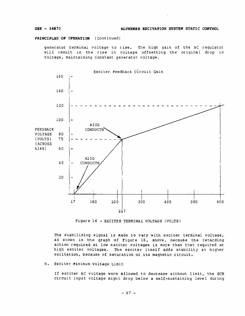
GEK - 14870 ALTERRRX EXCITATION SYSTEM STATIC CONTROL
PRINCIPLES OF OPERATION (Continued)
generator terminal voltage to rise. The high gain of the AC regulator will result in the rise in voltage offsetting the original drop in voltage, maintaining constant generator voltage.
Exciter Feedback Circuit Gain 160
140
120
100
FEEDBACK VOLTAGE 80 (VOLTS) 75 (ACROSS Al4R) 60
40
20
A3ZD
Figure 16 - EXCITER TERMINAL VOLTAGE (VOLTS)
The stabilizing signal is made to vary with exciter terminal voltage, as shown in the graph of Figure 16, above, because the retarding action required at low exciter voltages is more than that required at high exciter voltages. The exciter itself adds stability at higher excitation, because of saturation or its magnetic circuit.
b. Exciter Minimum Voltage Limit
If exciter AC voltage were allowed to decrease without limit, the SCR circuit input voltage might drop below a self-sustaining level during
- 67 -
AL!l!BRREX EXCITATION SYSTEM STATIC CONTROL GEK - 14870
PRINCIPLES OF OPERATION (Continued)
a transient condition (such as load rejection). This means that when the transient condition is past and the regulator tries to increase excitation, the SCR circuit has no voltage - the excitation system has collapsed. To prevent this, a limit circuit is provided to take control from the AC regulator, when required, and hold exciter AC voltage at some minimum preset value.
Zener diode AlZD connects the exciter feedback auxiliary circuit to the AC regulator principal circuit as well as being part of the non-l inear stabilizing circuit. A basic amplifier stage and output emitter follower are supplied from the AC regulator power supply, and a comparison circuit is supplied from the exciter voltage signal developed across ARC. This comparison circuit is used to supply the input signal to the amplifier stage.
By a common connection of the emitters of output NPN transistors A3Q and A33, the first logic, or decision-making function, is incorporated in the regulator. This is an “OR” connection, the polarity of which estaolishes that whichever transistor has the higher voltage on its oas e 4111 have control of the junction of the emitters of A3Q and A43. Thus, the voltage-divider ratio of the comparison circuit, controlled oy AlP position, the transformer ratio (ANT, A2T, A3T), and other components of this auxiliary circuit determine the exciter voltaGe at which transistor A3Q will take over SCR firing COntrIO from
A4Q.
Tracing the symbol, A, through this portion of the regulator shows that :n~s circuit would try to move the junction of the emitters of A3Q and A4Q down. It will be assumed that the junction of the emitters of A3Q and A4Q is usually held up by A4Q, so that the signal at the ease of A3Q does not get through. Of course, this depends on the level of generator voltage and several other factors. But, the low voltage limit comes into operation upon action reversed from that indicated by the symbol, 6 , preventing the voltage at the junction of the emitters of A3Q and A4Q from being reduced below a value which would drop the exciter voltage below the setpoint of AlP.
C. Generator Field Current Limit
In this auxiliary circuit, current limit CTs are used to obtain a voltage signal proportional to exciter line current, or generator field current. The primaries of these CTs are also in series (with the DC regulator CT primaries) in the current boost CT secondary lines to the current boost bridge. The secondaries of the current limit CTs are connected in delta and loaded by resistors across each secondary winding, and by a three-phase full-wave rectifier bridge and DC load resistors. The DC components are shown in Figure 16. Rectifier s A29D through A40D make up the bridge, while UlOR, A43R, A44R, and A13P comprise the DC load.
- 68 -
GBK - 14870 ALTBRNBX EXCITATION SYSTEM STATIC CONTROL
PRINCIPLES OF OPERATION (Continued)
Note: High wattage resistors of both regulators, and of the underexcited reactive-ampere limit circuit are located on separate panels, designated 3S7932MD163 - these resistors are identified by the prefix, “U”.
Thyrite resistor AlTHY keeps the- voltage from becoming dangerously high, if the current should become abnormally high. Capacitors A9C and AlOC smooth out fluctuations due to commutation of the main field rectifiers. The AC and DC loading resistors, which are approximately equal, convert the current signal to a Voltage Signal. Potentiometer Al3P is used in a voltage-divider network, with A43R and A44R, to pick off part of this voltage signal as an input to the first stage amplifier of the AC regulator. Diode A28D, reverse-biased at low current, incorporates the “OR” logic function at that point. Also, the current limit circuit is allowed to override the generator terminal voltage signal by working through a smaller base resistor (A36R) than the other path (A35R).
The symbol, ?I , indicates action of the current limit circuit for a sample case of excessive generator field current. This may be a case of a system fault near the generator, and the AC regulator is increasing excitation. The increased generator field current results from an increase in exciter output current, which will cause the output current from the CTS to increase. The voltage on the anodes of A32D, A36D and A40D will move down. The wiper of Al3P will move down and pull the junction of A36R, ~35R and the anode of A18D down, taking Control from the AC regulator. symbol 6 ,
This will cause action opposite to the to lower the junction of A4Q and A3Q emitters and decrease
excitation. During the time when the current limit is in control, the excitation system is operating as a generator field current regulator . Since, during the time when the current limit might be required to act, the generator terminals might be shorted, provision is made to supply voltage for the transistor circuits at that time from the output of the current limit bridge through resistors U~R and U9R.
d. Phase-Back Limit
The purpose of the minimum firing angle limit is to ensure that the SCR bridge will invert, when it is supplying reverse output voltage during those times when the regulator acts to reduce the excitation rapidly . Without the phase-back limit, the reset voltage could become so high that the SCRs would not be fired at all. Then, instead of inverting, the SCR bridge would apply single-phase AC voltage to the exciter field, through the two SCRS still conducting.
In Figure 17, the components of the phase-back limit circuit consist Of A13R, A12R, AllR, AlOR, A2P, A2ZD, A16D, A6Q, and A5Q. Transistors A6Q and A5Q form a DarlingtOn pair. A voltage level at the arm of A2P is applied through A16D to the base of A6Q which, in turn, controls
- 69 -
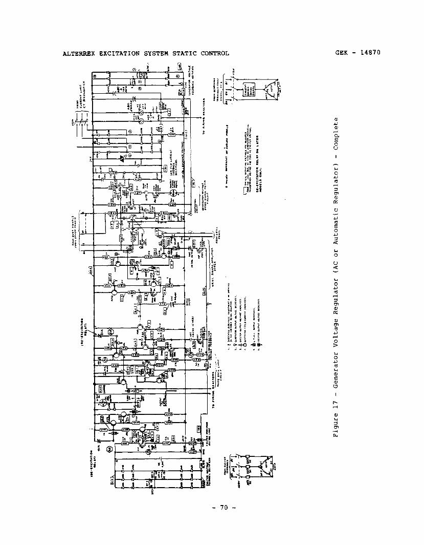
STERREX EXCITATION SYSTEM STATIC CONTROL GEK - 14870
I
u 0
GEK - 14870 ALTERRKX EXCITATION SYSTEM STATIC CONTROL
PRINCIPLES OF OPERATION (Continued)
A5Q. Transistor A5Q operates in an “OR” relationship with transistors A4Q and A3Q. ‘Whichever of the transistors A5Q, A4Q or A3Q calls for the highest level at their junction will assume control of the exciter field. A component of exciter voltage signal is introduced into the minimum firing angle circuit from the exciter minimum voltage limit at junction of AlR, U4R, and A4R through resistor AlOR. The purpose of this is to help maintain the minimum phase limit at a constant value despite the wide range of exciter output voltage. Without it, the limit would not stay constant, but would advance itself somewhat at higher exciter voltage levels.
e. URAL Amplifier
The output from the URAL sensing and comparison circuit is a DC voltage proportional to underexcited reactive current error. The error signal is applied to the URAL amplifier across A7C to the base Of Al3Q. Filtered by A7C-A, this signal is applied through A37R to the input of an amplifier stage consisting of A13Q, Al2Q, A33R, A32R, A31R, ABP, and A20D. This amplifier stage is similar to the first stage of the AC regulator amplifier already described. Potentiometer A8P is used to adjust URAL gain.
The output of this stage is introduced through Al9D to the input of the first stage of the AC regulator amplifier. Thus, both the amplified URAL signal as well as the error signal of the AC voltage input comparison circuit can control the AC regulator amplifier. Because these signals are fed into the amplifier through diodes A18D and Al9D respectively, whichever signal calls for the higher excitation will assume control; this is another “OR” decision point. The gain for the URAL signal up to this point greatly exceeds the gain for the generator voltage signal to this point, so this provides a hard underexcited reactive-ampere limit, in a similar manner to the hard generator field current limit.
To prevent rapid limit cycling when the URAL takes over from the generator voltage signal, additional exciter voltage rate stabilizing is incorporated into the first transistor of the URAL amplifier Stage.
f. Error Meter
The next auxiliary circuit of the generator voltage regulator is the generator voltage error signal meter circuit. Components of this auxiliary circuit are meter A2VM, potentiometers Al2P and A14P, resistors A40R and A41R, and pushbutton switch AlPB. A Voltage divider circuit is connected in parallel with the principal comparison circuit, across A8C, and A8C-A, the output voltage of the regulator front end.
- 71 -

ALTERREX EXCITATION SYSTEN STATIC CONTROL GEK - 14870
PRINCIPLES OF OPERATION (Continued)
The DC voltage from this divider circuit is proportional to generator terminal voltage; potentiometer Al2P is used to pick off 24 volts (from the A40R end of the circuit), when the generator terminal voltage is at its desired value. A sensitive iIIiCrOaRWteter, in series
with calibrating resistors (multipliers), then is used to make a differential voltmeter. This meter has a limited range, from minus 5% to plus 5%. It is located beside the regulator output voltmeter, AlVM, and provides a quick check of the regulator operation. When the error meter circuit is activated by pushing switch AlPB, the two meter pointers should be observed to move together, in the same direction, and approximately over the same arc. This indicates that the regulator output voltage is faithfully following the generator voltage deviation. Switch AlPB protects the meter when generator voltage is low during startup, or when maintenance disconnect switch AlSW is open, or when the signal PTs are disconnected, etc.
4. Figure 17 also shows where takeover signals from other panels, such as the exciter field current limit panel, and the Volts/Hertz regulator panel, are applied.
The takeover signal from the exciter field current limit panel is applied through a normally back-biased diode and a 1K resistor, just like the signal from the generator field current limit circuit.
The Volts/Hertz regulator takes over by introducing a voltage between the -24 VDC reference and A38R, which is proportional to generator freqUenCY.
When the generator frequency is at rated, the signal at A38R is essentially 0 volts, which would be equivalent to the volts/hertz regulator being inoperative or switched out with A6SW.
If the voltage introduced between A6SW-2 (-) and A6SW-4 (+), is called eHZf then it can be said that eHz - EC, (EC, is 24V, the AIZD voltage 1 is introduced between A6SW-4 and A6SW-6. At SO/60 HZ, eHz is about 25v, and it will drop in proportion to a drop in frequency. -Thus, point J is about 1V positive with respect to OV (common) at SO/60 Hz, and begins decreasing to zero, becoming negative at lower frequencies. In effect, this is cheating the regulator front end, making it appear that the generator terminal voltage has risen, as the voltage at points within the comparison circuit drop. (Note that a drop in generator voltage, , causes the voltage on the wiper of 9OP to rise.) R Referring again to t e Characteristic Equation of the regulator of Figure 13, the introduction of eHz has the following effect:
Regulator Output voltage = G[KKlEL - (1 - K)eHz] - (GK - 1)Ecc.
Since the regulator acts to keep its output voltage constant, now to keep the term in brackets, above, (being the only term containing variables)
- 72 -
GBK - 14870 ALTBRRBX EXCITATION SYSTEM STATIC CONTROL
PRINCIPLES OF OPERATION (Continued)
constant requires that KK~E~ change exactly as (1 - K)eRs changes. This causes EL to drop in proportion to a drop in eHz, resulting in regulator action which keeps the ratio of EL to eHZ constant.
The remaining items on the AC regulator panel are maintenance disconnect switches, exciter fuses, an output voltmeter, and free-wheeling diodes, as on the DC regulator panel.
Also, on newer models, a de-excitation circuit is provided; one function of this circuit is to cause the AC regulator to operate at the phase-back limit. This is accomplished by connecting the base of transistors A2Q to A7Q to their emitters, with an external sealed relay. These connection points are shown in Figure 17.
EXCITER FIELD CURRENT LIMIT AND OVERCURRENT RELAYS (Refer to Figure 18)
This circuitry is contained on three or four panels. Two of the panels are identical, and consist of three window-type current transformers. These panels are designated 3S7932MA288A8 and A9. The current transformer primary windings are the lines from the anode transformers to the SCR bridges. The secondary windings are connected in wye, and are then connected to the Current Limit Panel, 3S7932JA115, for loading and signal measuring. On late model regulators, this connection is made to parallel the two sets of CT secondary windings. Thus, the current in the loading resistors is the sum of the bridge currents, transformed. This voltage is proportional to the exciter field current, whether both bridges are in service or not. Each CT group of the earlier models is loaded by a delta-connected resistive load, and by a three-phase full-wave rectifier bridge with an ad justable DC loading resistor. The DC load is in series in the two circuits; all other components are duplicated for each SCR-rectifier section. This is done so that the sum of the bridge currents will determine the voltage across the DC load, approximately . The first models of this panel had the rectifier bridges connected in parallel instead of series. This made the circuit an SCR bridge current limit rather than an exciter field circuit current limit, as the SCR bridge with the higher current would establish the voltage across the DC load.
On the DC side, the circuit is like the current limit circuit for the generator field (on the AC regulator panel), where a portion of the direct voltage is picked off by potentiometer ElP, and input to the first amplifier stage of the AC regulator, through a high-gain resistor and a diode which is back-biased except at high current.
The DC voltage generated by the CTs, rectifier bridges, and loading resistors is also used to operate two static overcurrent relays, designated 76 and 50. Relay 76 is energized by operational amplifier EVA (this operational amplifier may also be designated lo), connected as an integrator. The operational amplifier, relay 76, and associated transistors are powered by a 24VDC
- 73 -

I--
L Ill
U
T-
ta -3
IX
Figu
re
18
- Ex
cite
r Fi
eld
Cur
rent
Li
mit
And
O
verc
urre
nt
Rel
ayin
g
GEK - 14870 ALTERRRX EXCITATION SYSTEM STATIC CONTROL
PRINCIPLES OF OPERATION (Continued)
SUPPlY - This supply is obtained from Zener diode regulator ElZ (may also be designated 1Z) , which is driven through resistor E15R (may also be designated 12R) from the current limit rectifier bridges. At low values of exciter field circuit current, ElA is in negative saturation, approximately +2v (measured from the negative side of the Zener 1. This state is called negative saturation by comparison with the bias voitage to the non-inverting input of ElA set by resistor ElOR (3R) and thermistor E13R (4R). When the current reaches the threshold set by E2P (1P) , EVA output begins to increase, charging E2C (lc) at a rate determined by the position of E3P (2P), the magnitude of EllR (5R), and the voltage at E2P (1P) wiper; E3P is used to adjust the rate, setting the time delay for a given value of overcurrent. When the output voltage of ElA exceeds NV, transistor ElQ (1Q) is turned on. conduction of ElQ causes conduction of E2Q (20) and E3Q (30). E3Q supplies additional base current to ElQ, resulting in a positive switching-on of relay 76. The inverse- time circuit works in conjunction with the current limit circuit to allow the excitation system to deliver forcing current up to the thermal limits of the system components. The threshold and time adjustments are set to allow twice rated exciter field circuit current for 60 seconds, and any current up to rated for an infinite time. Rated exciter field circuit current is alWayS greater than rated exciter field current (EAFFL). The rated circuit current is determined, in conjunction with the 2.0 per-unit 60 second forcing capability, to be that required for desired response to system faults or other disturbances while providing adequate exciter and generator protection.
Relay 50 is a back-up to the current limit circuit and to relay 76. It operates instantly if the current exceeds 2.222 times the rated exciter field circuit current. Relay 50 alS0 removes power from the timing circuit for relay 76, preventing damage to those components.
When either relay operates, SCR firing control is transferred to the DC regulator, which is limited to rated exciter field current (EAFFL). The circuit rating is established for an ambient temperature of 50°C.
Thermistor E13R compensates for the thermal change in ElZ voltage, and also lowers the threshold current and increases the integrator rate at higher ambient temperatures.
The earliest models of the equipment had two sets of mechanical overcurrent relays , instead of static relays. One set was connected in each SCR-rectifier circuit, prior to paralleling. This connection provided bridge overcurrent protection. Later models had only one set of mechanical relays, in the exciter field circuit. Relay 76 had an inverse-time characteristic obtained from a solenoid-type construction utilizing a dashpot filled with silicone fluid. Threshold current is adjusted by changing the initial position of the plunger in the solenoid barrel. Time delay is adjusted by uncovering holes in the dashpot piston. Relay 50 is an instantaneous direct current relay. It is adjusted by changing armature spring restraining force. The settings are the same as for the static relays, in per-unit current and time delay.
- 75 -

ALTERREX EXCITATION SYSTEM STATIC CONTROL GEK - 14870
PRINCIPLES OF OPERATION (Continued 1
REACTIVE CURRENT COMPENSATOR
This equipment is provided to prevent the-generator with the most responsive excitation system from supplying more than its share of reactive current to the power system when the power system is accepting VARs, or from rejecting a disproportionate share of reactive current when the power system is supplying VARs . Reactive current compensation is generally required on all, or on all but one generator when there are several generators in a power station.
The elementary and phasor diagrams are shown in Figure 19. The phase sequence of the generator and the polarities of the transformers cause a voltage to be introduced in the line from phase 2 before it is connected to the generator voltage regulator front end, phased so that this voltage cheats the front end. This makes it appear that the generator terminal voltage has changed when it has not, when reactive current is supplied by the generator.
The consecutive phasor diagrams under Part I of Figure 19 show that under- excited reactive current causes a decreased voltage signal to the regulator front end. This results in an increase in excitation - thus reducing the underexcited reactive current. The next diagram shows that excitation resulting in 1.0 power factor operation of the generator does not appreciably affect the voltage to the front end of the regulator. The last diagram shows an opposite action to the first.
The reactive current compensator is often called the droop circuit, as its effect is to make the generator voltage versus reactive load characteristic curve have an artificial droop.
There are only three parts to the compensator: an isolating transformer/ reactor and two selector switches which vary the transformer ratio from zero to its full turns ratio. One switch provides coarse steps in ratio and reactance while the other switch provides fine steps. The switch positions are numbered 0 to 20 in four steps for the coarse switch, and 0 to 4 in four steps for the fine switch. The numbers are the actual voltage added in the regulator sensing circuit, for a current of 5 amps in the signal CT secondary circuit. The signal CT ratio is usually set so that 5 amps will be induced in its secondary winding when slightly more that rated generator line current is in its primary. Thus, primary reactive current of that magnitude can cause a 24V change in the nominal 115V phasor generator voltage triangle. This will change the average voltage from the rectifiers of the regulator sensing circuit by 11%. So, the compensator can induce somewhat less than 11% voltage droop in the generator-regulator characteristic at rated generator current.
Note that the compensator can be connected in reverse polarity to cause negative droop in the generator characteristic: this connection can be used to account for output transformer reactance, thereby improving system voltage regulation.
- 76 -

i I
I r-
----
----
j,x,
, \ b-
3
; S
EE
FI
G
18
____
____
---
;
Figu
re 19
- E
leme
ntar
y An
d Ph
asor
Di
agra
ms Fo
r Re
acti
ve Cu
rren
t Co
mpen
sato
r An
d Ac
tive
-Rea
ctiv
e Cu
rren
t Co
mpen
sato
r

ALTERREX EXCITATION SYSTEM STATIC CONTROL GEK - 14870
PRINCIPLES OF OPERATION (Continued)
IT IS ESSENTIAL TEAT BOTH WINDINGS OF THE COMPENSATOR BE CONNECTED IN THE SAME GENERATOR PHASE - USUALLY PHASE 2.
ACTIVE/REACTIVE CURRENT COMPENSATOR
This compensator consists of the reversed reactance connection described on the preceding page. It has identical components as the reactive current compensator. In addition, it contains a rheostat in series with the reactance. The rheostat is used to cause a change in voltage to the regulator sensing circuit proportional to generator active current.
The active and reactive current compensator is used to reproduce in miniature, at the regulator, the resistance and reactance between the generator and some predetermined point in the system. The function of the compensator is to lower the signal voltage to the AC regulator as the generator load increases. This causes the regulator to maintain normal voltage at some predetermined point in the system, regardless of changes in the voltage drop over the system impedance between the generator and this point. (See Figure 19-11.)
Where line-drop compensation is required on several generators in a station, provision can be made to prevent interference between the compensators. This is accomplished by special connections of the current transformer and compensators.
The resistance portion of the compensation is a 5 ohm rheostat which produces 25 volts drop in the regulator signal with five amperes in the CT secondary.
Figure 19 shows the connections for this device when used with a single generator. Insulating windings are provided for both the reactor and resistor to permit grounding the current and potential transformer secondaries separately. Again, it is essential that the current transformer be in the same phase as the signal-voltage line in which the compensator is connected.
The theoretical equation which applies to the signal voltage at the regulator front end is given on the next page, following definitions. The equation calculates the average full-wave rectifier bridge at the front of the AC
the list of 'Terminology' DC voltage from the 3-phase, regulator.
Terminology
EL - Generator line-to-line voltage, rms
IL - Generator line current, rms
PF - The power factor is the cosine of the phase angle between generator phase voltage and current in that same phase. The angle is defined as
- 78 -
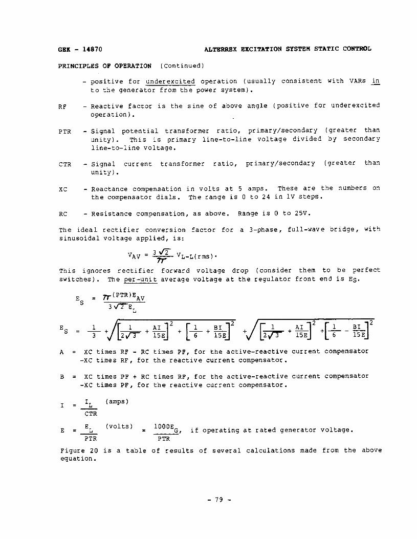
GEK - 14870 ALTRRRRX EXCITATION SYSTEM STATIC CONTROL
PRINCIPLES OF OPERATION (Continued)
- positive for underexcited operation (usually consistent with VARS in - to the generator from the power system).
RF - Reactive factor is the sine of above angle (positive for underexcited operation).
PTR - Signal potential transformer ratio, primary/secondary (greater than unity). This is primary line-to-line voltage divided by secondary line-to-line voltage.
CTR - Signal current transformer ratio, primary/secondary (greater than unity).
xc - Reactance compensation in volts at 5 amps. These are the numbers on the compensator dials. The range is 0 to 24 in 1V steps.
RC - Resistance compensation, as above. Range is 0 to 25V.
The ideal rectifier conversion factor for a 3-phase, full-wave bridge, with sinusoidal voltage applied, is:
‘JAV = - VL-L(rms) l
rr This ignores rectifier forward voltage drop (consider them to be perfect switches). The per-unit average voltage at the regulator front end is ES.
E S = &PTR)EAV
3 flEL
1 Es = 3+ I+ t a2 t [+ t zJ2 tj[+ + %I2 +[+ - $&I2 [
A = XC times RF - RC times PF, for the active-reactive -XC times RF, for the reactive current compensator.
B = XC times PF t RC times RF, for the active-reactive -XC times PF, for the reactive current compensator.
current compensator
current compensator
I = IL ( amps 1
CTR
E EL (volts) = = 1OOOEC I if operating at rated generator voltage.
PTR PTR
Figure 20 is a table of results of several calculations made from the above equation.
- 79 -
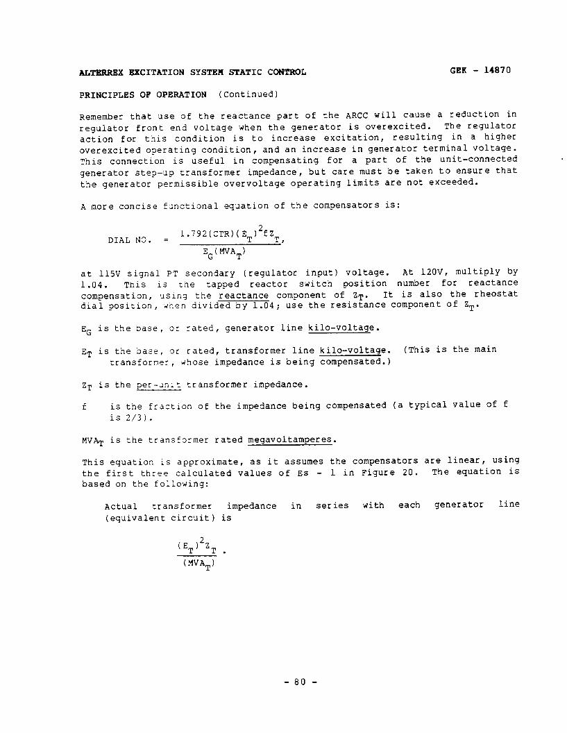
ALTKRREX EXCITATION SYSTEH STATIC CONTROL GEK - 14870
PRINCIPLES OF OPERATION (Continued)
Remember that use of the reactance part of the ARCC will cause a reduction in regulator front end voltage when the generator is overexcited. The regulator action for this condition is to increase excitation, resulting in a higher overexcited operating condition, and an increase in generator terminal voltage. This connection is useful in compensating for a part of the unit-connected generator step-up transformer impedance, but care must be taken to ensure that the generator permissible overvoltage operating limits are not exceeded.
A more concise functional equation of the compensators is:
DIAL NO. = 1.792(CTR)(ET)2fZT I
EG( MVAT)
at 115V signal PT secondary (regulator input) Voltage. At 120V, multiply by 1.04. This is the tapped reactor switch position number for reactance compensation, <using the reactance component of ZT. It is also the rheostat dial position, h’nen divided by 1.04; use the resistance component of ZT.
EG is the base, or rated, generator line kilo-voltage.
ET is the base, or rated, transformer line kilo-voltage. (This is the main transformer, whose impedance is being compensated.)
ZT is the per-Jnlt transformer impedance.
f is the fraction of the impedance being compensated (a typical value Of f is 2/3).
MVAT is the transformer rated megavoltamperes.
This equation is approximate, as it assumes the compensators are linear, using the first three calculated values of Es - 1 in Figure 20. The equation is based on the following:
Actual transformer impedance in series with each generator line (equivalent circuit) is
( ET j2ZT . (MVAT)
- 80 -
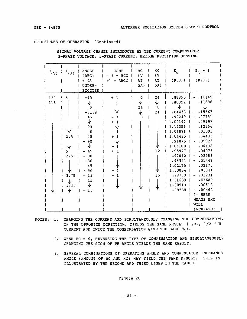
GEK - 14870 ALTERREX EXCITATION SYSTEM STATIC
PRINCIPLES OF OPERATION (Continued)
SIGNAL VOLTAGE CHANGE INTRODUCED BY THE CURRENT COMPENSATOR 3-PHASE VOLTAGE, l-PHASE CURRENT, BRIDGE RECTIFIER SENSING
CONTROL
I I I I I I I I 1
; E(V) / ‘(A) / :;;;; / COMP I RC 1 XC I ES I ES - 1 I
- 1 = RCC ( (V I (V I I I I I I + IS I +l = ARCC I AT 1 AT I (P.U.) I (P.U.) I I I l UNDER- 1 I 5A) I 5A) I I I I I EXCITED I I I I
I I I I I I I I I I I I I I I I I I I I I I I
120 115
I 5 I -90 I I I& I
I 0 I l -31.8 I
I
111
IT / 90 I
I 0 I I 2.5 I 45 I
I 4 I-Y j I5 l-45 I l 2.5 l - 90 I
I 3.75
; 1’25 .
- 30 I 45 I
-90 I - 15 I
15 I + l
I v I-15 I I I I I I I I I I
+1
1 I I
- 1 I + 1 I
\1/ l - 1 I + 1 I
+ I - 1 t1 I
i ; - 1 •t 1 I
4
I I I I I I I
0 / 24 1 .88855 1 - .11145 + I 4 l .88392 I .11608 24 I 0 I JI
:I l I I I I I 1.09197 1.12356 1.01091 1.04435 1.06108 .94075
I 12 I .95927 ‘:I l I I I 1.03034 1.02175 .98551 .97012
I 15 I .98769
I I I 1.01689
+ - .15567 - .07751
.09197
.12356
.01091
.04435
I I I I I I I I I I I I I
I 1.00513 I I .99538 I - .00462
I I l (- HERE I I l MEANS EXC I I I WILL
- .05925 .06108
- .04073 - .02988 - .01449
.02175
.03034 - .01231
.01689
.00513
I I 1 I I I I I I I I I I I I I I I I I I
NOTES: 1.
2.
3.
CHANGING THE CURRENT AND SIMULTANEOUSLY CHANGING THE COMPENSATION, IN THE OPPOSITE DIRECTION, YIELDS THE SAME RESULT (I.E., l/2 THE CURRENT AND TWICE THE COMPENSATION GIVE THE SAME ES).
WHEN RC = 0, REVERSING THE TYPE OF COMPENSATION AND SIMULTANEOUSLY CHANGING THE SIGN OF TH ANGLE YIELDS THE SAME RESULT.
SEVERAL COMBINATIONS OF OPERATING ANGLE AND COMPENSATOR ANGLE (AMOUNT OF RC AND XC) MAY YIELD THE SAME RESULT. ILLUSTRATED BY THE SECOND AND THIRD LINES IN THE TABLE.
Figure 20
- 81 -
IMPEDANCE THIS IS
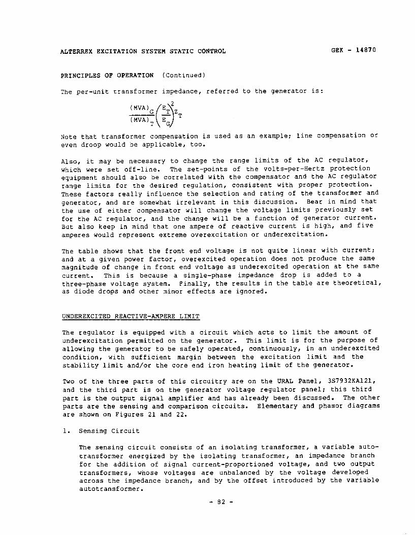
ALTERREX EXCITATION SYSTEM STATIC CONTROL GEK - 14870
PRINCIPLES OF OPERATION (Continued)
The per-unit transformer impedance, referred to the generator is:
Note that transformer compensation is used as an example: line compensation or even droop would be applicable, too.
Also, it may be necessary to change the range limits of the AC regulator, which were set off-line. The set-points of the volts-per-Hertz protection equipment should also be correlated with the compensator and the AC regulator range limits for the desired regulation, consistent with proper protection. These factors really influence the selection and rating of the transformer and generator, and are somewhat irrelevant in this discussion. Bear in mind that the use of either compensator will change the voltage limits previously set for the AC regulator, and the change will be a function of generator current. But also keep in mind that one ampere of reactive current is high, and five amperes would represent extreme overexcitation or underexcitation.
The table shows that the front end voltage is not quite linear with current: and at a given power factor, overexcited operation does not produce the same magnitude of change in front end voltage as underexcited operation at the same current. This is because a single-phase impedance drop is added to a three-phase voltage system. Finally, the results in the table are theoretical, as diode drops and other minor effects are ignored.
UNDEREXCITED REACTIVE-AMPERE LIMIT
The regulator is equipped with a circuit which acts to limit the amount of underexcitation permitted on the generator. This limit is for the purpose of allowing the generator to be safely operated, continuously, in an underexcited condition, with sufficient margin between the excitation limit and the stability limit and/or the core end iron heating limit of the generator.
Two of the three parts of this circuitry are on the URAL Panel, 3S7932KA121, and the third part is on the generator voltage regulator panel: this third part is the output signal amplifier and has already been discussed. The other parts are the sensing and comparison circuits. Elementary and phasor diagrams are shown on Figures 21 and 22.
1. Sensing Circuit
The sensing circuit consists of an isolating transformer, a variable auto- transformer energized by the isolating transformer, an impedance branch for the addition of signal current-proportioned voltage, and two output transformers, whose voltages are unbalanced by the voltage developed across the impedance branch, and by the offset introduced by the variable autotransformer.
- 82 -
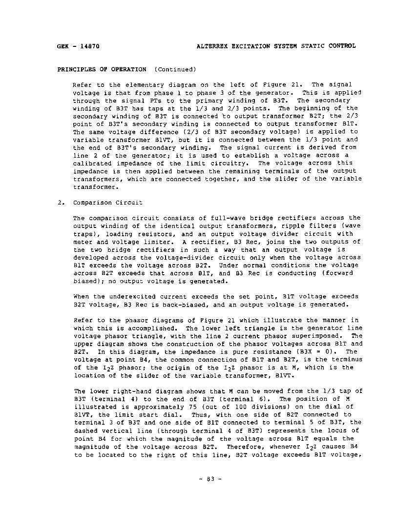
GEK - 14870 ALTERREX EXCITATION SYSTEM STATIC CONTROL
PRINCIPLES OF OPERATION (Continued)
Refer to the elementary diagram on the left of Figure 21. The signal voltage is that from phase 1 to phase 3 of the generator. This is applied through the signal PTs to the primary winding of B3T. The secondary winding of B3T has taps at the l/3 and 2/3 points. The beginning of the secondary winding of B3T is connected to output transformer B2T; the 2/3 point of B3T's secondary winding is connected to output transformer BlT. The same voltage difference (2/3 of B3T secondary voltage) is applied to variable transformer BlVT, but it is connected between the l/3 point and the end of B3T's secondary winding. The signal current is derived from line 2 of the generator; it is used to establish a voltage across a calibrated impedance of the limit circuitry. The voltage across this impedance is then applied between the remaining terminals of the output transformers, which are connected together, and the slider of the variable transformer.
2. Comparison Circuit
The comparison circuit consists of full-wave bridge rectifiers across the output winding of the identical output transformers, ripple filters (wave traps), loading resistors, and an output voltage divider circuit with meter and voltage limiter. A rectifier, B3 Ret, joins the two outputs of the two bridge rectifiers in such a way that an output voltage is developed across the voltage-divider circuit only when the voltage across BlT exceeds the voltage across B2T. Under normal conditions the voltage across B2T exceeds that across BlT, and B3 Ret is conducting (forward biased); no output voltage is generated.
When the underexcited current exceeds the set point, BlT voltage exceeds B2T voltage, B3 Ret is back-biased , and an output voltage is generated.
Refer to the phasor diagrams of Figure 21 which illustrate the manner in which this is accomplished. The lower left triangle is the generator line voltage phasor triangle , with the line 2 current phasor superimposed. The upper diagram shows the construction of the phasor voltages across BlT and B2T. In this diagram, the impedance is pure resistance (B3X = 0). The voltage at point B4, the common connection of BlT and B2T, is the terminus of the I22 phasor; the origin of the 122 phasor is at M, which is the location of the slider of the variable transformer, BlVT.
The lower right-hand diagram shows that M can be moved from the l/3 tap of B3T (terminal 4) to the end of B3T (terminal 6). The position of M illustrated is approximately 75 (out of 100 divisions) on the dial of BlVT, the limit start dial. Thus, with one side of B2T connected to terminal 3 of B3T and one side of BlT connected to terminal 5 of B3T, the dashed vertical line (through terminal 4 of B3T) represents the locus Of point B4 for which the magnitude of the voltage across BlT equals the magnitude of the voltage across B2T. Therefore, whenever 12Z causes B4 to be located to the right of this line, B2T voltage exceeds BlT voltage,
- 83 -

ALTERREX EXCITATION SYSTEM STATIC CONTROL GEK - 14870
PRINCIPLES OF OPERATION (Continued)
and there is no output. But when I22 causes B4 to located to the left of this line, BlT voltage exceeds B2T voltage, and an output signal is developed. The consecutive positions of B4 (a, b, c, and d) illustrate a variation in 12 from slightly overexcited to highly underexcited.
Note that for the condition, illustrated in Figure 21, of B3X = 0, the power component of 12 does not cause point B4 to move either closer to, or farther from the limit takeover line. The component of voltage which is UlR times the power component of 12 moves B4 parallel to this line. Thus, the URAL characteristic line of Figure 4(b) would be parallel to the abscissa, or have a slope of zero. This shows that, without power recalibration, the limit action is independent of the power load on the generator.
Figure 22 illustrates limit action with power recalibration. This rotates the 12Z phasor so that it is no longer parallel to the I2 phasor. Now, the component of voltage which is UlR + jB3X times the power component of 12 can cause point B4 to cross the limit takeover line, if the power component of 12 is of sufficient magnitude. Thus, the inclusion of power recalibration (B3X # 0) gives the URAL characteristic line a non-zero, positive slope. This acts to reduce the underexcited reactive current (or VA.Rs) to which the generator will be limited, as the generator output power increases. Since both limit functions (generator/system and URAL characteristic) are influenced by generator voltage, both lines will move closer to the origin if the voltage decreases, and both lines will move out if voltage increases. Therefore, when the URAL is set to provide a certain degree of margin, that margin will not be significantly affected by voltage changes.
- a4 -
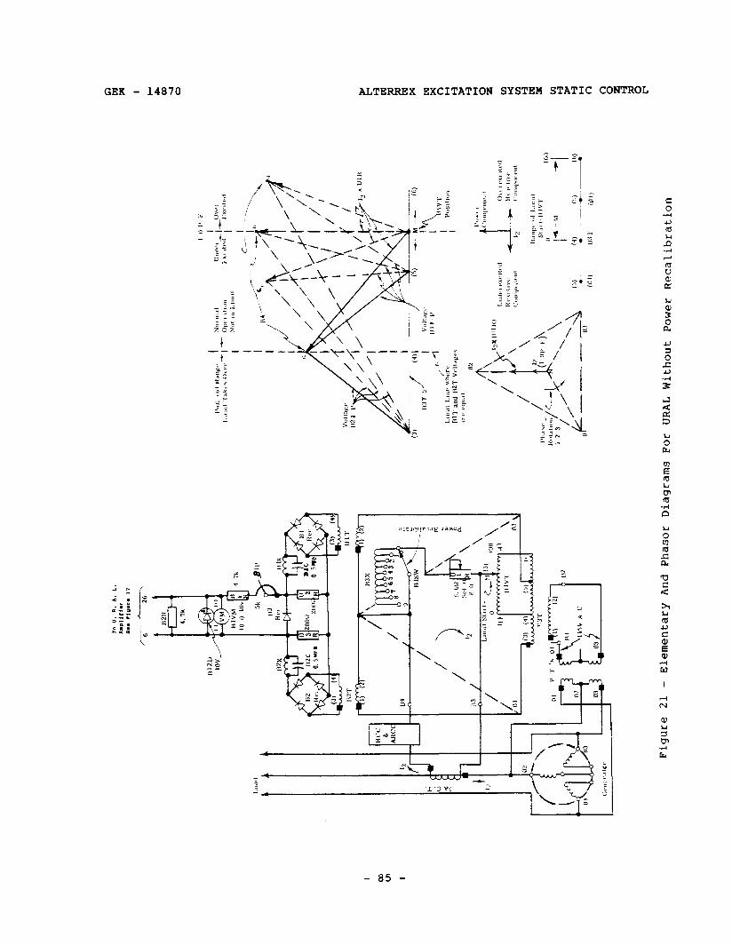
r /
‘2
/ J-
L - 2
Figu
re 21
- El
emen
tary
An
d Ph
asor
Di
agra
ms Fo
r UR
AL Wi
thou
t Po
wer
Reca
libr
atio
n
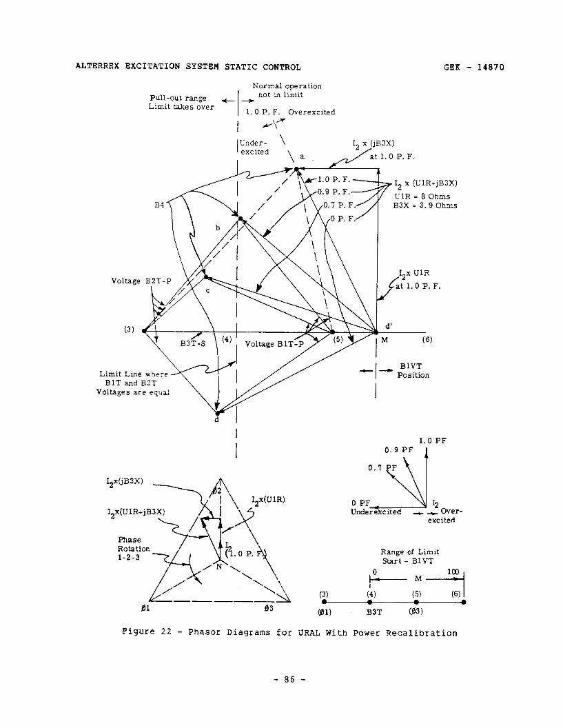
ALTERREX EXCITATION SYSTEM STATIC CONTROL
Normal operation Pull-out range - - not in limit Limit takes over 1.0 P. F. Overexcited
I fl\2
GEK - 14870
UlR = 8 Ohms B3X = 3.9 Ohms
Voltage B2T-P
----_ 41 83
Figure 22 - Phasor Diagrams for
1.0 PF
Over- excited
Range of Limit Start - BlVT
URAL With Power Recalibration
- 86 -
GEK - 14870 ALTERREX EXCITATION SYSTEM STATIC CONTROL
PRINCIPLES OF OPERATION (Continued)
RELAYING AND CONTROL CIRCUITS
Relaying and control circuits are operated by DC, which is supplied from storage batteries for maximum reliability. The source voltage is usually 125, although 25OV is sometimes provided instead.
Figure 23 illustrates a typical application. Most applications vary in some degree from this arrangement to suit the user's practice. The following control functions are usually provided:
Field Breaker(s) Regulator Transfer and Lock-Out Exciter Field Bridge Overcurrent Generator Field Bridge Overtemperature Exciter Field Flashing Motor-Driven DC Regulator Set Point Adjuster
The control circuits of the field breaker, device 41, are fused and are not interrupted by the DC control panel circuit breaker. The closing circuit and the trip circuits are fused separately: indicator lights show the breaker state, as well as the continuity of the trip circuit. Where a de-excitation circuit is furnished, indicator lights also show the de-excitation relay state.
The transfer relay, 43A, and its auxiliary, 43B, are energized by the operator's control switch, 43cs, providing that lock-out relay 83 is disabled. The lock-out relay is connected to the auxiliary and position switches of the field breaker so that operation in AUTO is prevented when the breaker is open and in operating position. This ensures that startup will be in MANUAL.
Another exciter field breaker auxiliary contact is used to return the DC regulator setpoint adjuster to its lower limit while the breaker is tripped.
Upon closure of the field breaker, when it is in operating position, the flashing contactor, 53, is energized for 10 seconds, after which it is de-energized by relay 53TD. Relay 53 applies the DC source voltage to an adjustable resistor, a reverse-current preventing diode, and the exciter field in series. The flashing resistor must be set with the DC voltage amplitude and field resistance so that sufficient flashing current will be provided to cause the exciter voltage to build up to a point where the SCR bridge can turn on, taking over excitation from the flashing circuit.
Relay 83 is the regulator trip relay, or trouble relay. When 83 picks up, it seals itself in and drops out the transfer relays, 43A and 43B. This returns the excitation system to MANUAL. Relay 83 can also be picked up by several other protective relays, such as those on the and those on the early volts/Hertz protective operation to be restored, the operator
- 87 -
maximum excitation limit panel panel. In order for AUTOMATIC must reset 43cs.
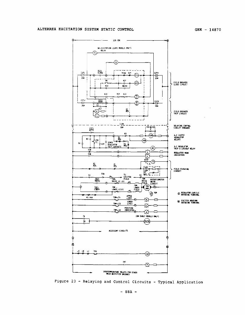
ALTERREX EXCITATION SYSTEM STATIC CONTROL GEK - 14870
115 YU
M-ExCITAT*M (LATE RXJELS OrnY) RELAI
FIELD BREAKER ’ CLOSE CIRCUIT
FIELD BREAKIn ’ TRIP CIRC”,,
A-C REwLATca TRIP 1 LOCKaJl ULA”
i
FIELD FUS”,~S ClXVlT
Figure 23 - Relaying and Control Circuits - Typical Application
- 88A -
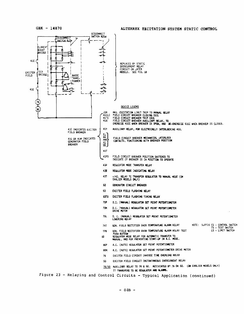
GEK - 14870 ALTERREX EXCITATION SYSTEM STATIC CONTROL
41E (
1
SCR BRIDGE
41E INOlCATES EXCITER FIELD BREAKER
416 OR 41H INDICATES GENERATOR FIELD BREAKER
J3K 4lCLC 4lTC 41X
41T
41PS L
43A
438
43T
52
53
6310
7OP
7OU
7OL
747
TPB
B3
90P
son
76
50
u
REPLACED BY STATIC OVERCURRENT RELAY CIRCUIT ON LATER NIOELS. SEE FIG.18
DEVICE LEGEND
MAX. EXCITATIOH LIMIT TRIP TO K4RUAL IIELAY FIELD CIRCUIT BREAKER CLOSING COIL FIELD CIRCUIT BREAKER TRIP COIL FIELD CIRCUIT BREAKER AUXILIARY RELAY, TO ENERGIZE 41CC UHEN BREAKER IS OPEN, AJFO L-EMERGIZE SlCC YHEN BREAKER IS CLOSED.
AUXILIARY RELAY, FM ELECTRICALLY IlilERLKKIHG 41X.
FIELD CIRCUIT BREAKER IEClL4NICAL INTERLOCK CONTACTS, FUNCTIONIC WITH BREAKER POSITION
FIELD CIRCUIT BREAKER POSITION SYITCHES TO INDICATE IF BREAKER IS IN POSITIOW TO OPERATE
REGULATOR COOE TRANSFER REUY
REGULATOR MOE INDlCATIffi RELAY
v/HZ. RELAY TO TRANSFER REWLATOR TO WUM rODE (ON EARLIER CDDELS ONLY)
GENERATOR CIRCUIT BREAKER
EXCITER FIELD FLASHlNG RELAY
EXCITER FIELD FLASHINQ TIMING RELAY
D.C. (MNW) REGULATOR SET POINT POTWIWTER
D.C. M'lNUAL) REGULATOR SET POINT POTENTIOMTER DRIVE MITOR
0. C. MANUAL) REWLATOR SEY POINT WTENTIOMTER LOYERIRG RELAY
GEN. FIELD RECTIFIER OVER TEWERATURE ALAIM RELAY
GEN. FIELD RECTIFIER OVER TEWERATUE ALARM RELAY TEST PUSH BUTTON REGULATOR MlDE RELAY FOR AUTOMATIC TWSFER TO WUAL, AN0 FOR PREVENTING START-Up IN A.C. WOE.
NOTE: SUFFIX CS - CONTROL WITCH TS - TEST WITCH LS - LIWIT SNITCH
A.C. (AUTO) REGULATOR SET POINT POTENTIOlETER
A.C. (AUTO) REGULATOR SET rnIwT POTEBTIOIETER DRIVE 140~0~
EXCITER FIELD CIRCUIT INVERSE TICE OVERLOAO RELAY
EXCITER FIELD CIRCUIT INSTANTANEOUS OVERCURRENT RELAY
AUXILIARY RELAY TO 76 1 So. MTIVIATED BY 76 OR 50. (CM EARLIER M0DELS MILY) ITTR~MSRRSTOKREGUATORAYDWD#.
Figure 23 - Relaying and Control Circuits - Typical Application (continued)
- 88B -
ALTERREX EXCITATION SYSTEM STATIC CONTROL
THIS PAGE INTENTIONALLY LEFT BLANK
GEK - 14870
- 88C -
GEK - 14870 ALTERREX EXCITATION SYSTEM STATIC CONTROL
PRINCIPLES OF OPERATION (Continued)
The exciter voltage regulator set point adjuster, 7OP, is usually motor driven, 70P and drive motor 70M being located in the regulator cubicle. Limit switches prevent excess rotation of 7OP, and illuminate lights to inform the operator of the limit being reached. A limit switch also provides position indication. The generator voltage regulator set point adjuster, 9OP, is often motor driven also; and an identical motor and control circuit is provided.
Note that the regulator will transfer to MANUAL, should DC control power to the regulator control circuits be interrupted. Also, when the power is restored, the regulator will transfer to AUTO and the exciter field will be reflashed. This may cause an excitation bump if the regulators are not set for equal excitation when the loss of power occurs. Field reflashing usually causes no interference, as the excitation will probably be above the flashing level (53D will be back-biased when 53 is re-energized). Latched transfer relays can be provided where loss of relaying power is likely to occur.
Each bridge of the generator field rectifiers contains two or three temperature switches on tne upper heat sink of each leg or DC header. When one or more of these is activated by high temperature, relay 74T is energized; this illuminates a lignt in the rectifier cubicle door and also alarms the operator. A test switch 1s provided in each bridge to check the operation of the circuit.
Optional accessory panels usually also require connection to the DC source for relaying power. Some of these accessories are the maximum excitation limit, the volts/tiertz protective panel, automatic tracking panel, and voltage matching panel. These accessories operate in conjunction with the control circuits discussed above, to provide further generator protection and/or several degrees of automation.
POWER RECTIFIE" CUBICLE
The power rectifier cubicle is covered completely by separate instructions. (See page 3.1
MISCELLANEOUS FUNCTIONS AND COMPONENTS
Shaft voltage suppressor circuits are provided across exciter and generator field circuits to provide a ground path for AC currents. This prevents the ripple component of the field rectifier output voltage from inducing voltage in the rotor shaft. Shaft voltage tends to cause current flow across bearings, which could shorten bearing life.
Transducers are provided on most applications for transmitting an isolated low power level signal to indicate generator field current and voltage. This signal is often fed to an associated computer for automated systems.
- 89 -
ALTERREX EXCITATION SYSTEM STATIC CONTROL GEK - 14870
PRINCIPLES OF OPERATION (Continued)
A field temperature indicator retransmitter can also be provided. It is usually located in the regulator cubicle, but requires connection to the collector rings (through main brushes or pilot brushes) and to a shunt connected in one of the buses between the rectifier cubicles and the collector rings. Outputs such as calibrated voltage or milliampere signals can be provided. Also, more than one output channel can be supplied to operate meters, relays, or computer conversion equipment. Early models had a retransmitting slidewire output; this requires a special measuring circuit - it cannot be input directly to a computer.
Space heaters can be provided in the regulator cubicle where moisture or cold weather protection is needed. Also, fans and filters may be furnished for unusually dirty environments.
Generator and exciter field ground detector relays are usually provided. Some- times an exciter phase fault detector panel, a voltage-matching panel, a voltage balance panel, an automatic tracking (or regulator null) panel, or other special panels may be included in the control. These are covered by separate instructions.
The transducers, ground detector relays, and field temperature indicator usually require power from a single-phase, 12OV, 60 Hz, preferred supply.
Control switches and a transfer voltmeter are usually provided for mounting on the user’s control board.
MAINTENANCE
TO PREVENT HAZARD OF ELECTRICAL SHOCK OR BURN, APPROVED GROUNDING PRACTICES AND PROCEDURES MUST BE ADHERED TO.
ISOLATION OF TEST EQUIPMENT FROM THE EQUIPMENT UNDER TEST PRESENTS POTENTIAL ELECTRICAL HAZARDS. IF THE TEST EQUIPMENT CANNOT BE GROUNDED TO THE EQUIPMENT UNDER TEST, THE TEST EQUIPMENT'S CASE MUST BE SHIELDED TO PREVENT CONTACT BY PERSONNEL.
- 90 -
GEK - 14870 ALTERREX EXCITATION SYSTEM STATIC CONTROL
MAINTENANCE (Continued)
The excitation control is static, having no moving parts except for relays and instruments, so little maintenance should be required. The control cubicle should be cleaned by vacuuming on a regular schedule. It is suggested that this cleaning be done at least once every six months and/or on scheduled shutdowns.
To remove dirt from places that are inaccessible with a vacuum cleaner hose (example - between heat sink cooling fins), a low pressure air hose may be used to loosen this dirt so that the vacuum cleaner may remove it.
I ---m
L CAUTION 3 ---m
DO NOT USE A METAL NOZZLE ON THE VACUUM CLEANER HOSE. IT CAN CAUSE COMPONENT DAMAGE AND/OR INSULATION BREAKDOWN. USE A RUBBER NOZZLE.
ALSO, DO NOT USE HIGH PRESSURE AIR. IF AIR PRESSURE IS TOO HIGH, COMPONENTS MAY BE DAMAGED.
If an accumulation of moisture is evident, space heaters should be installed.
If excessive vibration is present, all screw connections should be checked periodically. Exciter field SCRs should be checked weekly by observing their neon lamp or LED monitors. All lamps should glow with the same intensity, with one electrode in each lamp glowing more brightly than the other, ot the red (or yellow) LED glowing more brightly than the green LED.
Every three or four weeks the SCRs and current boost diodes should be checked with a clip-on ammeter (a non-saturating type is preferred for accuracy and for preventing possible meter damage). The six SCRs in the front section should carry approximately the same current, and the six SCRs in the rear section should carry approximately the same current. The ratio of front SCR current to rear SCR current should be the same as the ratio of front SCR bridge current (as read on RlAM) to rear SCR bridge current. The current boost diodes should all carry the same current, within 25%. RlVM should always indicate a positive voltage, R2VM (where supplied) should always indicate a slightly negative voltage (2V). RlAM should always indicate a positive current. R3VM should read approximately 25V. The field breaker trip circuit should be checked weekly to indicate integrity of the trip coil. Field ground detecting relay(s) should be tested weekly.
The excitation system should be transferred to DC (MANUAL) regulator weekly, to check circuit operation. This transfer should be smooth and control on MANUAL operation should be smooth. The transfer back to AC (AUTO) regulator should also be smooth. All transfers should be made with the TVM at 0 volts.
- 91 -
ALTERREX EXCITATION SYSTEM STATIC CONTROL GEK - 14870
MAINTENANCE (Continued)
Once every week or two weeks, while in AUTOMATIC, run 70P over its full range while observing meter DlVM; its variation should be smooth and always in the same direction.
A calibration curve should be established for 7OP, showing its general position required to track the AUTOMATIC regulator, as the generator power and reactive load is varied. This curve should be used to check the regulator power circuit frequently (once a week). Another check to make is to observe the regulator output meters, AlVM and DlVM - they should change only slightly from 3.5V, as the generator real and reactive loading changes.
The error signal meter (AZVM) may be recalibrated with A12P and A14P periodically, as operating voltage level is changed.
The URAL output meter (BlVM) should be checked weekly. It should normally read slightly negative (1V). The user may choose to operate the generator in the underexcited region periodically to check URAL operation.
Magnetically operated contact-making devices should be inspected regularly in accordance with applicable instructions. Brushes in motors (for all motor driven adjusters), all exposed rheostats, potentiometers, and variable transformers should be inspected every six months under normal operating conditions. Where unusually dusty or other abnormal atmospheric conditions exist, they should be inspected every six weeks. If arcing occurs, or if the brushes are badly worn, they should be replaced.
Input signals to regulator panels and auxiliary panels should be checked with a high impedance voltmeter every six months.
For planned outages, the following maintenance should be performed:
1. General cleaning - low pressure air and/or vacuum cleaner (see previous cleaning procedure).
2. Check all brushes, motors, rheostats, and variable transformers.
3. Inspect all relays - operation and contacts.
4. Check for any loose connections on large wire, bus, and large rectifiers.
5. Check all large rectifiers (those requiring heat sinks) and all large fuses with an ohmmeter.
Fuse resistance should be very low, in either direction. A good diode rectifier should show very high resistance when the ohmmeter positive lead is connected to its cathode, and a fairly low resistance (less than 10 ohms) with the positive lead connected to its anode.
- 92 -
GEK - 14870 ALTERREX EXCITATION SYSTEM STATIC CONTROL
MAINTENANCE (Continued)
With its gate open-circuited, of with its gate connected to its cathode, a good SCR should show a high resistance in both directions. But when the gate lead is connected to the anode, the resistance will drop in both directions, the anode/gate being very low, approximately 5 ohms.
6. Check the power rectifier cubicle as directed by separate instructions.
7. Check field breakers(s) for proper operation and worn or loose parts. Rack breakers out to accomplish a complete inspection. Refer to separate instructions contained in the turbine-generator instruction book.
TROUBLESHOOTING
GENERAL
There are two types of trouble, major and moderate. Major trouble is characterized by the regulator being unable to regulate: moderate trouble occurs when a component or circuit fails, but the regulator is still able to function. Major trouble can be further classified as that which drives the excitation too high and too low. A final division determines the degree of overexcitation or underexcitation. In the discussion below, major trouble will be called Category I Trouble; overexcitation will be called A, and underexcitation will B. Abnormal excitation within safe limits will be designated type 1, and abnormal excitation beyond safe limits will be called type 2. Moderate trouble will be classified as Category II Trouble.
The list below summarizes the trouble types, and the corresponding action required.
Trouble types:
Category I: Major - Regulator unable to regulate
A. Too high
1. Within safe limits - correction urgent but not critical.
2. Beyond safe limits - correction critical: if not corrected in short time, unit must be tripped (depending on degree, a fraction of a second to two minutes).
B. Too low
1. Within safe limits - correction urgent but not critical.
- 93 -
ALTERREX EXCITATION SYSTEM STATIC CONTROL GEK - 14870
TROUBLESHOOTING (Continued)
2. Beyond safe limits - unit must be tripped immediately.
Category II: Regulator still functioning, but with a component or circuit failure.
The following list tabulates the regulator components OK circuit where trouble may occur, with the resulting trouble type identified.
Trouble location:
Power Loop
SCRs and SCR fuses (I or II)
Anode transformers (I or II)
Collector rings (I)
Breaker and disconnect switches. (I or II)
Wiring and terminals (I or II)
Current boost CTs (II)
Current boost rectifiers (II)
Control Circuits
Trouble in output
SCRs firing full on - must be remedied quickly: as unit will be damaged soon (IA21
SCRs firing full off (not firing) - rapidly dangerous to unit and to system as pole-slipping will occur - must be remedied immediately (IB2)
Trouble in one regulator - MANUAL or AUTO. TVM off and cannot be nulled.
Limited range - TVM will deflect (II)
No control - TVM will not deflect (II)
Control action oscillating - TVM doing the same: SCR firing angle would be limited or not stable if transfer were made. (IAl, IBl, and/or II)
- 94 -
GEK - 14870 ALTERRBX EXCITATION SYSTEM STATIC CONTROL
TROUBLESHOOTING (Continued)
POWER CIRCUITS
The regulator is designed to have a very high degree of reliability: this requirement is fundamental to the entire excitation system. In the main (generator field) power circuit , multiple rectifier paths with each path fused separately, provide ample current capacity in the event of failure and clearing of one or more paths.
The three-phase full-wave rectifier bridge, which is the basic block of the system, is capable of providing DC to the generator field in 45 of the 62 possible failure (open leg) combinations. The amplitude of the DC available in these combinations depends on the number and arrangement of open legs. If one leg is open, the average (DC) voltage from the bridge will be 5/6 of its voltage capability; if two legs are open, the average voltage available will be 2/3 of l/2 of its voltage capability, depending on the arrangement of the open legs. The least available voltage is l/3, of the remaining 24 operable failure states, and this condition is obtained in 18 of the 20 possible combinations of three open legs, and in 6 of the 15 possible combinations of four open legs. Thus, the regulator could keep the excitation up to the required level in these instances by raising the exciter AC voltage. Of course, an increase in exciter voltage of 200% (to offset a 67% rectifier DC voltage decrease) cannot be expected, if full rated generator field voltage is required to be maintained.
But to ensure against any failure, redundant paths are used, with each path fused for self-clearing. This practice, combined with conservative application design margins, renders the failure probability extremely low.
The same practices discussed above are used in the SCR bridge supply to the exciter field; redundant circuits with independent leg fusing and isolating disconnect switches. The current boost rectifier bridge is also duplicated. With individual anode transformers and firing circuits, including gate clipping circuits, the two exciter field power supplies are located in the regulator cubicle as identical half-sections. As in the generator field rectifier bridges, the disconnect switches (which completely isolate the circuits for maintenance) are key-interlocked so that only one section at a time can be removed from service.
Should a failure occur in the generator field rectifiers or in the exciter field rectifiers, the most likely result is that the redundant path(s) will pick up the current, and no change in excitation will occur. But even if all redundant paths should fail, the regulator firing angle will increase so that, again, no change in excitation will result. If other failures occur to the extent that all redundant paths of one or more additional rectifier legs become open, the regulator will be able to further increase the firing angle to maintain the required excitation, for the majority of the possible failure combinations.
- 95 -
ALTERREX EXCITATION SYSTEM STATIC CONTROL GEK - 14870
TROUBLESHOOTING (Continued)
The purpose of preparing a calibration curve for 7OP, or of frequently observing meters AlVM and DlVM, discussed under MAINTENANCE, is to watch for a change in SCR firing angle, which will indicate this type of trouble in the power circuits.
The intended conclusion which can be made from the preceding discussion is that the probability of a component or path failure in the power loop of the regulator and/or in the generator field power circuit, which results in loss of excitation, or in limited excitation, is very slight indeed.
Where a neon lamp or LED is out, first check the lamp socket. Or measure the AC voltage across the associated SCR. If the lamp circuit is good, and no voltage is across the SCR, its fuse is probably blown, and the SCR may be shorted. Measure the SCR current with a clip-on ammeter (non-saturating type is preferred for accuracy and for preventing possible meter damage).
If an SCR is not firing, its corresponding SCR in the other bridge will not be firing, either, or will otherwise be incapable of carrying current. Thus, the two electrodes of a neon lamp will glow with equal brilliance, or both red (or yellow) and green LEDs will be equally bright. If this condition is observed, check the indicator for the corresponding SCR in the other bridge: it, too, will probably give the same indication, or it may be out. Check the continuity of both fuses with an AC voltmeter; check the AC voltage across both SCRs; and check both SCR currents with a clip-on ammeter. There will probably be wiring trouble, or trouble in the phase voltage to or from the anode transformer, or firing circuit trouble in that phase. Use an oscilloscope and the waveforms of Figures 7, 8, and 10 to trace the source of the trouble.
If the current in an SCR is zero, check the firing pulse to the SCR - if it is like the other SCR firing pulses, and similar to that shown in Figure 8, then the SCR is open-circuited and must be replaced.
If the firing pulse is absent, or low in amplitude or duration, check the gate clipping voltage at the firing circuit board terminals, B and C. It should be a rectangular wave of 20V amplitude and about a 4:l on-off ratio (t2OV for 145", OV for 350, -20V for 145O, OV for 35O, etc.). If this voltage is acceptable, check the reset voltage on saturable reactor terminals (1) and (2) on the firing circuit board: terminal (2) is terminal G on the board and terminal (1) is the junction between the two diodes and the 5.6K resistor on the board. This voltage should be like e, of Figure 8, with a 6th harmonic ripple superimposed on the negative half-cycle portion of it: the average voltage during the reset half of the cycle should be the voltage shown on the output meter of the regulator in service, AlVM or DlVM.
If these voltages are acceptable, the firing circuit is faulty and should be replaced. If the voltages are not acceptable, the wiring from the board to the regulator or to the gate clipping transformer should be checked. If the
- 96 -
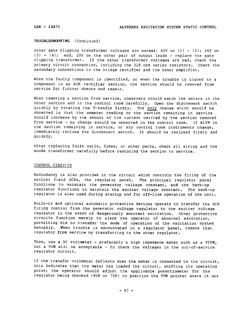
GEK - 14870 ALTERREX EXCITATION SYSTEM STATIC CONTROL
TROUBLESHOOTING (Continued)
other gate clipping transformer voltages are normal: 40V on (1) - (2); 24V on (3) - (4): and, 20V on the other pair of output leads - replace the gate clipping transformer. If the other transformer voltages are bad, check the primary circuit connection, including the 310 ohm series resistors. Check the secondary connections to the bridge rectifier and the Zener amplifier.
When the faulty component is identified, or when the trouble is traced to a component in an SCR rectifier section, the section should be removed from service for further checks and repair.
When removing a section from service, observers should watch the meters in the other section and in the control room carefully. Open the disconnect switch quickly by rotating the T-handle firmly. The only change which should be observed is that the ammeter reading on the section remaining in service should increase by the amount of the current carried by the section removed from service - no change should be observed in the control room. If RlVM in the section remaining in service, or any control room instruments change, immediately reclose the disconnect switch. It should be reclosed firmly and quickly.
After replacing fault cells, fuses, or other parts, check all wiring and the anode transformer carefully before restoring the section to service.
CONTROL CIRCUITS
Redundancy is also provided in the circuit which controls the firing Of the exciter field SCRs, the regulator panel. The principal regulator panel functions to maintain the generator voltage constant, and the back-up regulator functions to maintain the exciter voltage constant. The back-up regulator is also used during startup and for off-line operation of the unit.
Built-in and optional automatic protective devices operate to transfer the SCR firing control from the generator voltage regulator to the exciter voltage regulator in the event of dangerously abnormal excitation. Other protective circuits function merely to alarm the operator of abnormal excitation, permitting him to transfer the mode of operation of the excitation system manually. When trouble is encountered in a regulator panel, remove that regulator from service by transferring to the other regulator.
Then, use a DC voltmeter - preferably a high impedance meter such as a VTVM, but a VOM will be acceptable - to check the voltages in the out-of-service regulator circuit.
If the transfer voltmeter deflects when the meter is connected to the circuit, this indicates that the meter has loaded the circuit, shifting its operating point: the operator should adjust the applicable potentiometer for the regulator being checked (9OP or 7OP) to position the TVM pointer where it was
- 97 -

ALTERREX EXCITATION SYSTEM STATIC CONTROL GEK - 14870
TROUBLESHOOTING (Continued)
before the meter was connected. Then, record the meter reading. The voltages should be very nearly those shown on Figure 14 or 15, whichever is applicable. When checking a suspected faulty component, vary the voltage-adjusting potentiometer (9OP or 7OP) to determine where in the amplifier circuitry the signal becomes disrupted, distorted, or limited.
When the fault part is identified, open all the maintenance disconnect switches on the panel, and make the repair. If the component is on a printed circuit board, remove the board from the panel to a location where the board can be worked on with a small, sharp tip soldering iron and long-nosed pliers. Use the pliers on the component on the front of the board, and use the iron on the rear of the board, being careful not to separate the conducting material from the board. With the tip of the iron, bend the component leads out straight - then apply more heat and pull the component lead through, pulling from the front. Be sure to heat sink semiconductors before applying heat - the pliers can usually serve this purpose.
TROUBLESHOOTING GUIDE
The Regulator Troubleshooting Chart, Figure 23, is intended as a summary and guide, and not as a rigid procedure to be followed. This chart certainly cannot come close to being a substitute for an operator's knowledge and experience.
Its application is based on rapid analysis of the trouble situation, and ready access to the regulator cubicle.
A faulty regulator panel is thus quickly removable from service where it can be repaired with power removed from it. The maintenance checks listed earlier will identify a faulty SCR rectifier section, and it, too, can be quickly removed from service and de-energized, allowing repairs to be made.
- 98 -
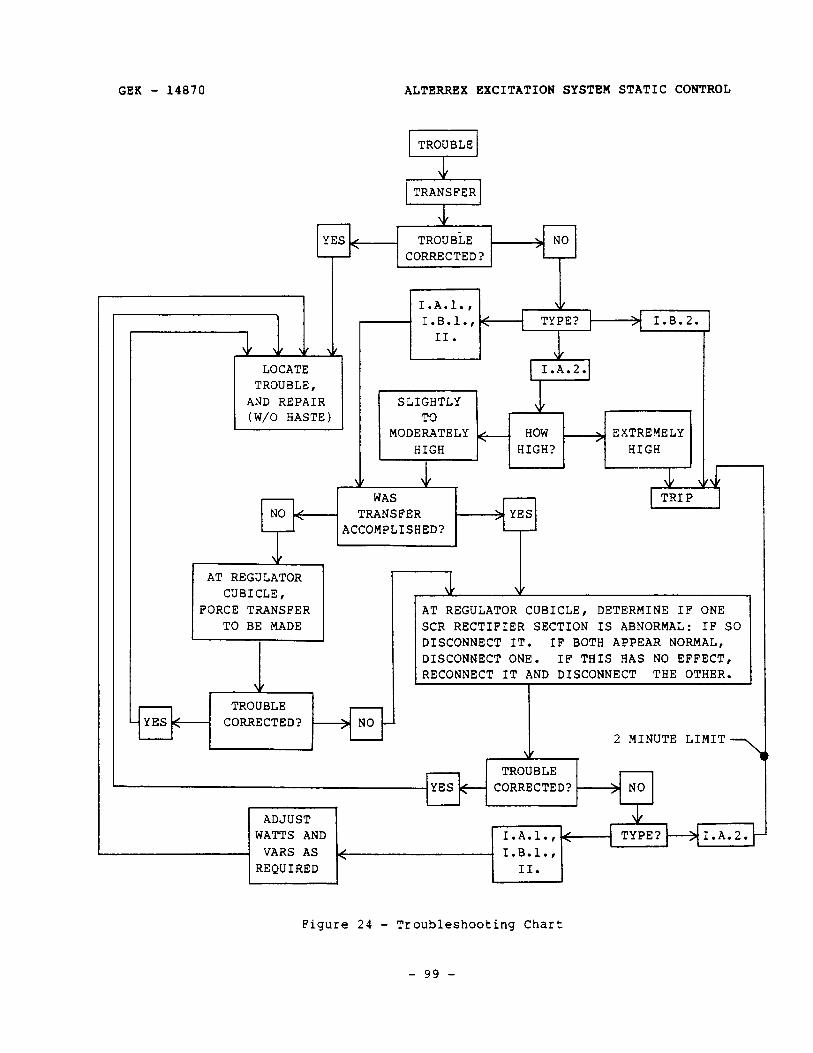
GEK - 14870 ALTERREX EXCITATION SYSTEM STATIC CONTROL
AND REPAIR
I.A.l., V I.B.l., < TYPE? I.B.2. II.
I I \L 1 I.A.2.1 1 I
TROUBLE
TRANSFER
, YES < TROUBLE
CORRECTED?
FORCE TRANSFER TO BE MADE
AT REGULATOR CUBICLE, DETERMINE IF ONE SCR RECTIFIER SECTION IS ABNORMAL: IF ! DISCONNECT IT. IF BOTH APPEAR NORMAL, DISCONNECT ONE. IF THIS HAS NO EFFECT, RECONNECT IT AND DISCONNECT THE OTHER
CORRECTED? l- 2 MINUTE LIMIT
TROUBLE AYES CORRECTED?' ) NO
I I I ADJUST
WATTS AND - VARS AS < REQUIRED
v I.A.l.,< TYPE? I.B.l.,
II.
SO I , .
Figure 24 - Troubleshooting Chart
- 99 -
ALTERREX EXCITATION SYSTEM STATIC CONTROL GEK - 14870
RENEWAL PARTS
A principal parts list and a list of recommended spares is furnished with each unit.
When ordering renewal parts, the following_information should be given:
1. Catalog number stamped on the part, with complete description including use and location.
2. Complete nameplate data appearing on the assembly that included the component.
3. If possible, data on original order on which equipment was first supplied, including all numerical references, especially generator serial number.
- 100 -
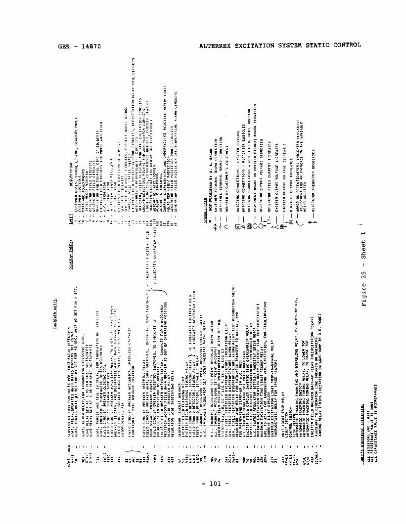
$2
- :I
- ,1
10
- 64
FI
- ca
r2
- 64
F3
- 1M
-
70”
-
IO”
- 70
,s
- 26
-
26,
- 26
/X
- 26
15s
- 83
-
SOP
-
:t -
9ou
-
:::
1 J2
YX
-
JjX
- 21
-
JIX
- XX
-L,
- XX
-CS
- XX
-,$
- A,
. -
A,A
- Al
/R
- .,A
-
52/*u
x -
x, -
D.C
. IY
AN
UIL
~ “~
Cul
rron
SC
, P
O‘“1
A
I~~O
S4A
1 0a
‘“C
uo1o
a D
.C.
I UA
NU
AL
, Ac
oI”_
*,O”
SC
I PO
,“1
“101
0,11
1 G
c”I”
AlO
” r,E
Lo
A~C
l,F,~
R
O”L
Rl~
w‘R
lr”“c
AL
A”‘1
1”
C”Y
Al.
*:*1
00
(Lb,
I_
0 LC
=
LCC
1,
LC
C
e,
LCC
C
) C
T”.
TI
CID
“C
C
lF‘I”
O
”CAl
~YPt
RAl
”AC
‘H
O‘C
Al,“
C
L‘C
lll
f M
N.
FltL
o R
CC
,‘F,~
R
OYc
Rrc
uPc”
II”R
E ~L
AR
Y
R‘L
I”
CC
”.
FltL
D
AE
CllF
lfR
OV
fRlE
UP
lRllU
RE
AL
A””
RC
LAV
rc
sr P
”SH
Bul
rON
S
.llC
H
R~C
”Ll,O
R
Ylo
r R
ELl
Y
FOR
A
uroY
Lllc
lA
AN
SFc
R
10
YlH”
lL,
AND
FOR
PRCY
C”,,“
C S,
IA,-U
P I”
L.C.
M
ODE
A.
C.
lAU,
O)
RCCU
LA,O
R sr
, PO
I’I,
RIIC
OS,
A,
EXCI
ICR
F,CC
D Cl
RC”l
, IW
YCRS
E ,I”
E O
VEAC
URRf
”1
“CC&
V CX
CIIIR
Fl
CLD
ClRC
”,,
I”S,
4”,A
”EO”
S OV
ERCU
ARC”
l “C
LAY
A.C.
(A
U,O
) Rt
C”l.l
,OR
Sc,P
oI”,
A”
lOS,
A,
DR‘V
C UO
lOR
UlXl
uJ”
CXC1
,l110
” Sc
”S*“
o fw
.IY
(IIIV
EASE
1I
Yf
CHIR
AC,E
RIS,
‘C)
LIAx
*wtI
~XCI
117I
OIl
IIUE
LIUI
, PI
CKUP
RE
LAV
AUX.
10
J2
X -
FOR
A”“O
”“CI
NG
“IX.
fX
CI,A
,IOIl,
FO
R RE
CALI
t!4A,
I”G
CUAR
CH,
L‘W
, CI
RC”‘
, I!A
XIW
U cX
cI,*,
*ow
LINT
TR
*P-,o
-YLM
LL
RCL.
LV
,H~R
UOS,
*,‘C
RCLA
Y FO
R SP
ACE
HfA,
CRS
“U,,
torII
) TR
IP
REl.A
V LI
YI,
SIIIC
H CO
W,R
OL
SII,C
H lE
S1
syc’
t A”
Kn4
IC
RACX
D(fi
EIIA
OLI
NO
AND
OISM
LnG
REL*
V.
OffR
AKD
BV
*,s.
AU,o
ulIC
,R
ACXI
HO
SUIIC
H.
AU,O
YL,IC
,R
ACX*
WG
Imm
o R
EU
I.
10 L
oYR
7w
A
UT
OW
ITIC
T
R*C
I*II
C Trn
mri
RC
UI,
To
f4a.
f 70
~
CXCI
lCR
rril_
o BR
LAXC
R BA
CX-U
P RE
tA”
(orc
Xcr,*
,rO”
“CLA
Y)
IUXI
LARV
TO
G
CHER
I,OR
LINE
BR
EAXC
R O
R e”
EAKC
AS
lRI,H
c lE
tA”
(1RI
PS
LxCI
~*,IW
on
uu
o Du
w I”
O.C
. W
ooc)
p-J -
O
”rC
OI”
C
co”“
ccrIo
”s
- E
XC
llCR
,4
0”,‘“
0
A
- O
II1G
O‘“C
C
ON
”CC
,IOI,S
-
“LC
,‘f
‘CA
CU
BlCL
ES
@--
O”,
COfN
C CO
WllE
C,lO
llS
- M
I,.
FIEL
D.
0ftv
.R.
HOUS
‘HC
0 -
COUP
ONE
N,
BOIR
D O
R PH
IN,fD
CI
RCUl
, BO
ARD
TlRY
‘NAL
S
91
CIllC
RAlO
R O
UTPU
, YO
L,AC
E O
ECRC
ASCf
J
u -
CCtlE
AAlO
R FI
ELD
CURR
C”,
,“CR
E)IS
ES
b-
EXCI
TER
OUTP
”,
“Ol_
,lCE
IllCR
EASE
S
Ip&Y
1XCI
lEA
O”,P
”,
VOLT
AGE
DECR
EASE
S
U.A.
A.L.
O”
,PU,
‘“
CREI
SCJ
Figu
re
25
- Sh
eet
1 ’
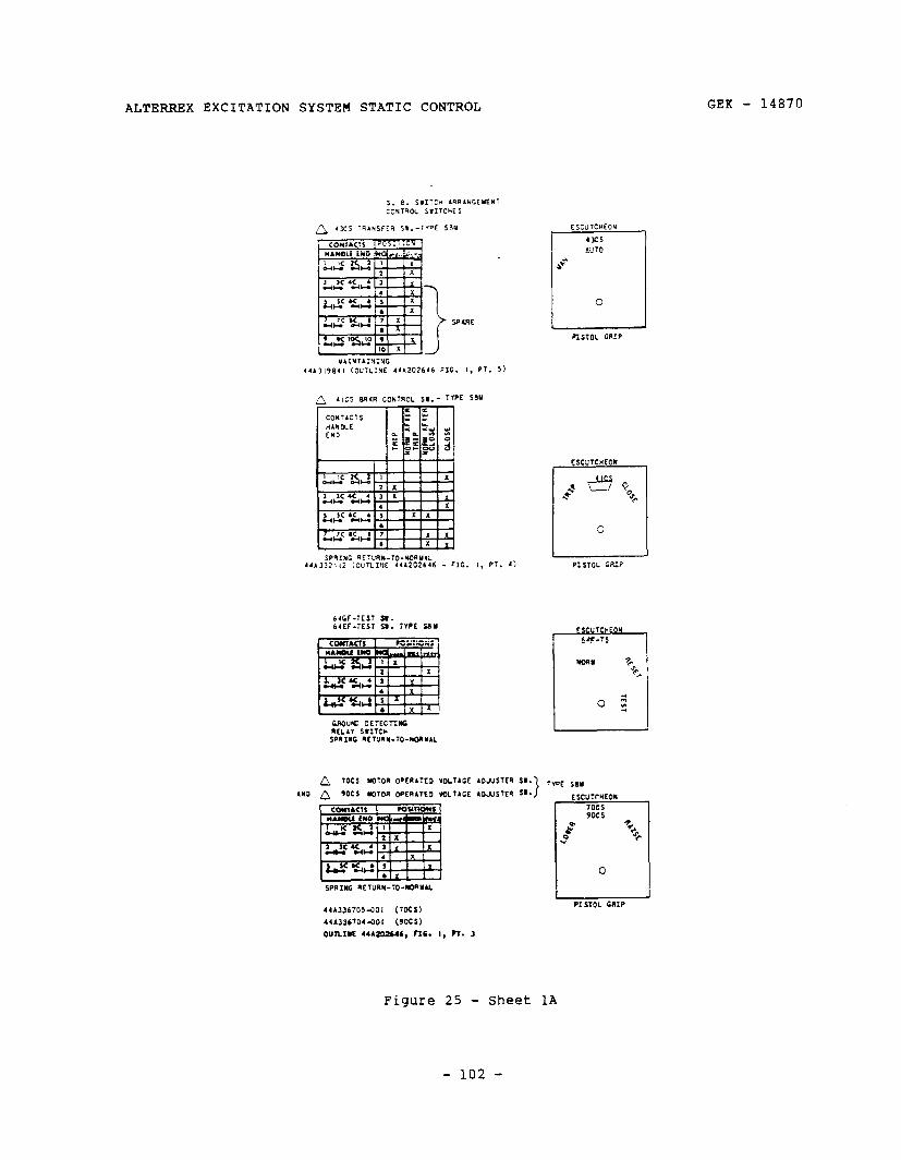
ALTERREX EXCITATION SYSTEM STATIC CONTROL GEK - 14870
44~1,984, (OUTLINE 441202646 FIG. I, Pi. 5)
SPRING RfTURI(-:O-YOnYu 4‘1332112 (CuTLIllE 441202646 - FIG.
ESCUTCHEON
64Cf-TEST S.. 64Ef-TEST 5.. TYPE 581
n ,OCS WfOR OPCRAIED YOLTLGE
A YOCS m7OR OPERATED voLTLCE
SPRING NETURN-TO-NORMAL
sm. , SM. 1
I ESCU 7C”EON
I
rn-7c I
WE SOY
ESCUTt%EO*
7OCS YOCS
3 +r d
Y 0 r 0
r I PISTOL GRIP
44A336705dOl (7OCS)
441336704~01 (YOCS)
ounm 4443o2646, ns. I, n. 3
Figure 25 - sheet 1A
- 102 -
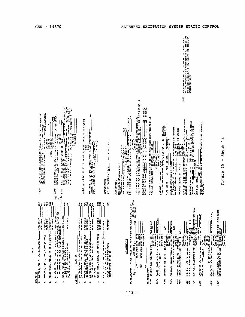
1.
UPtR
S,
FIEL
D,
No-L
OAO
(C*r
NL)--
sp
cc1t
-1c0
AO
C NA
SUAC
O
AOC
2.
_RcS
. TI
CLO.
FU
L-LO
AD
(CAF
fLb-
- SP
CCIr1
co
AOC
lKAS
”AC0
*o
c
,. nc
S1Sl
ANCx
. FI
ELD.
*t
2s.c
(C
RF25
)--
SPcc
1rIc
o O
HI
lKAS
”REO
-0
m
,. A.
vo
cts,
CI
CLO
, Fl
u-LO
AD,
CICL
O
AT
t*,*c
(G
VFFL
)---
I).
luxI
clcw
Pc
fw4I
SSIn
Lc
cONr
muO
us
OPC
RAlIH
C VO
LIAG
C----
c.
W
LxIP
aH
PcnM
Issx
eLc
CICL
O
lcwc
RAlU
Rc
------
-----_
_ =
I).
VOLl
S,
FICL
O.
FUL-
LOAD
(C
VFRL
)-----
CALC
uLAl
cO_V
OC
t.25
I GA
TFL
x GR
F?5
(TIC
LO
Al
ASSV
CO
OPC
AAlrn
C wA
swc0
1c
wcRI
lunc
O
F 9o
.C)
_VO
C
KLU
X!
WYX
L NO
.
I. 2.
5.
4. s.
I t-’
upcn
cs.
TIcL
o,
NO-L
OAD
(C
AFW
L)---
SP
cCIrI
cD
AOC
(GcN
cnAl
oN
FIEL
D oP
tn-c
IRcu
rlco)
~A
SUIC
O
AOC
UocR
cs.
FICL
O.
FUL-
LOU)
(C
AfFL
b--
sPcc
1FIc
o AO
C (C
CtER
*lM
Al
WTL
A&
O
GVfn
L)
IcAS
w(cO
AO
C ^_
..__
.___
-ii
S ii
ii.D
, Si
iii ~m
ttu~
u(--
_ _.
. ~.
.___
FI
ELD
Ai
0.8
WNL
AM
0 2S
.C
CALC
u.Al
L”
ilx
ICAS
URCO
AO
C (C
AlwN
)
RcSI
Slu(
Cf.
FIIX
O.
Al
2S.C
(C
RFIS
)- SP
CCIF
IEO
)(C
ASUF
KO
VOLT
S FH
LO,
FUL-
LOAD
(C
VfNb
---
CALC
LU.A
lCO
1.
3s
I CA
fFL
x ER
F2S
VOC
(FIc
LO
Al
ASSI
WO
OP(
RAlIN
C @
KASU
((CO
tc
(Isru
lwu
Of
90.C
) vo
c
~JUS
tffNl
~
0 W
OC
#CL#
.AlO
R -
R.&C
c R)
(CO
SlAl
S FO
R “P
PCR
AM0
LOYR
Lm
IlS
f-OR
I cl
-
VAC
AhO
c2
-
(SEC
GC
N.
OAt
A
DIP
-AC
48.
A6O
Vf)
)(EAS
W(C
O (fA
CtO
RI
OZP
02R
AC
Rf:o
LkAT
oR
AW
:
A2P
I
AS
P:
AdPI
ASP,
A
6Pi
Alo
P
A,W
:
A12P
;
CXCI
lCR
LOV
VOLt
AtiC
Lm
IT
- SE
T FW
E
VAC
PW
SC
LI
MIl
- se
t To
n YI
LLIs
cC.
Al
po
N2.
SCCO
WO-
SlAc
E W
m
- SE
, FO
R 4
rccO
eAJz
st
uxuz
mri
- NO
SP
cCIF
Ersr
vrnG
. FA
CtOt
t”
SC,
Al
“ID-
P,
(ON
sIlc
i d.
” sc
nrcs
sl
AIIIl
_Izm
c -
NOT
USED
. FI
RST
St&c
GA
IW
- SE
, FO
R 2
V/v.
FACT
OR”
loN
SIlC
! -
_ _.
__.
__-
_ ii.
ti.A.
L.
SCliC
S *ra
BIt_
Izmti
irdi
usco
. U.
R.A.
L.
GAIN
AO
J”Sl
-
FACl
ORt
SC
, Al
(O
N 51
” 8.
0
V.R.
A.L.
FE
COBA
CX
SlAB
dIL1
2mC
- NO
~~
FA
ClO
RV
SE,
AI
‘;&-ll
INc
CCNC
RAlO
R VO
LTAG
E CC
M,.
AOJ”
i:”
----
6.0
WIT
H AO
P,
FOR
1Ily
i 7(
;
_VO
C
V.
-.C.
A,P
:
A,,P
:
EIP
:
CCHE
RAlO
R F1
CLO
O
VCRC
URRf
Nl
ADJU
St
- SE
T A,
FA
CtOR
” TO
Ll
HIl
VOLt
AGL
ON
AlO
C TO
11
5 V”
C.
,“I5
S”r,w
O CO
HRCS
PONO
lo
1.
4 ”
C*ffL
. VI
IH
“lOA
PR
OPCH
L”
AOJ”
Slc0
.
ERRO
R SI
GNAL
CA
LIER
Atr.
tlASc
0 04
u1
y Al
ZE
RO
ERRO
R.
CX
ClT
CR
FI
ELD
CURR
CNT
LIM
Il SC
1 FO
R A
RESI
StO
R c7
RA
SE,
At
76.
S VO
C AC
ROSS
C
IC
OwiS
.~il
RESU
LT
IN
ATlX
RTTD
““
‘Nt
SPCC
IF
ICO
AB
OVC
. RC
CA,
76
Y1I.C
EN
LHCt
lL
IN
60
SFCO
NIlS
At
t”
Al
CURR
ENt
(SUS
lAIH
CD).
RLCA
” 50
W
ILL
CNCR
CIZC
IT
1l
C VO
LtAG
C O
N Cl
C CX
CCCO
S 8,
.Jv.
U.R.
A.CL
-
6tVl
Al
15
. Bl
SY
At
3,
RESE
, C,
, SI
TE
As
~0~L
0w.5
: tl,
Vl
BlSW
,1
c Iy
_<,,r
cC
IIN*
I -Y
.-c Y
s0.m
. . .
. .
.._ -
.-“..L
.,L
...“”
La-
Ala
“l-n
I” -I
LL””
w 1
” Lm
IlS
RVAR
S IN
10
ZE
RO
Al
-’ ur
o SI
P:
SCNS
IlIVI
tr SC
1 AI
~OW
CNSA
lOflS
SET
81
rAC,
ORV
At
m
SE
T O
N SI
lc
Al
ACtC
SSO
RICS
IUXI
CIII
cXCI
lAt1
ON
LIY,
, lR
AJlS
FOI#
R IA
P Jt
K HO
LUIN
G
VOL
bra%
: ::’
-A
C SE
, O
N SI
lc
Al
J,Pi
1O
OU
*f-FL
AD
JUSt
. Se
t to
HO
LO
cm
VAC
LmIl
CIAC
UIl
VOLT
AGE
ACRO
SS
AlO
C 10
(2
5 VO
C Al
IC
LO
CURR
ENt AO
C.
RELA
Y 1U
SC
1 FO
R 4S
ScC.
FO
R NO
. 1
fAC
RCLA
V t”
SC
1 FO
R XF
OR
NO.
2 iF
ACT-
@:
8:::j
:
VOLT
S-PC
R HA
12
RCG
MlO
R SE
7 l0
lA
I(c
OVE
R O
PERA
tIC.,
FRO
M
AC
AUlo
IulIC
‘IR
ACKI
NG
CIRC
UI,
TRW
SFER
Vo
CtAc
E O
IFfC
RCNl
IAL
Sft
FOR
z _t
& FA
CTOR
”
TIrC
DE
LAV
SE,
FOR
45
SEC.
O
N SI
tc~
VOLT
AGE
MAt
CHm
O
ECUI
- HI
P 0A
LANC
C PO
~CNT
IOCC
~~R
Scl
FOR
RE@
JIRE
O CE
NERA
~OR
VOLl
ACC
SIGN
AL
OF
1,s
V.
VOLt
ACc
SIGN
AL
OF
115
V.
, AN
D SV
SlEM
“2P
GAIN
RH
COSl
Al
~CCR
CIZE
AN
0”
lP”l
RELA
Y YH
(N
VOLT
AGE
IS
b!Is
MAl
ClEO
tl”
1.
0s
; O
R m
aE
(FAC
!!zE)
-
(ON
SIIE
)
.- . . .
_..
POlrC
R St
SlCM
ST
ABIL
IXR
m
CLSC
wfR
E.
StffN
lS
ARE
RECO
ROCO
(on
SIlC
vO
LtAk
~c
c$At
” VO
LtAG
E RA
NCE
A
ERRO
R SI
GNAL
AD
JUST
-
SC7
Al
fACl
BRVn
M7C
RO
YllH
tE
WRA
lO(I
VOLt
AGE
CR
RO
R
Figu
re 25
- Sh
eet
1B
NOlE
:
AOJU
StIF
HlS
ARE
RECO
ROCO
AS
O
lAC
POSI
TIO
NS
OF
tH
RHEO
STAT
O
R PO
tcNl
IO~t
CR.
l”CS
c AR
E Hl
WCR
EO
LIHE
ARL”
C-
,0.
CXCC
Pt
AIP
1~3”
AS
P YH
IC”
ARE
O-12
.
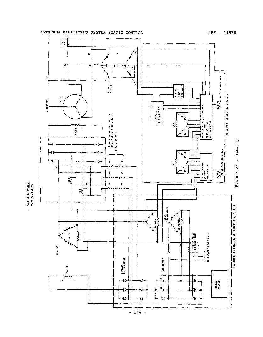
r _-
---
1 1
4
--T
C”l
UU
”,
BOOS1
OFUD
Ct
I
---.4
s+ ’ W
C
SH
CC
l 7.
8 1
I r-
oc
MLlAGE
loJUSlcR
c Y
OLl
)lCE
ra
Jusr
r
I -I
__--
-__
_I_j
I
RC
CU
l.llO
R
AM
0 C
OH
TRO
L C
‘RC
”,,S
L_ --
- --
---
---e
-I
lXCI1G-I FIELD
CIRCUIIS
Sit
SHCtlS
3,6,lO,lI,l2
Figu
re
25
- Sh
eet
2
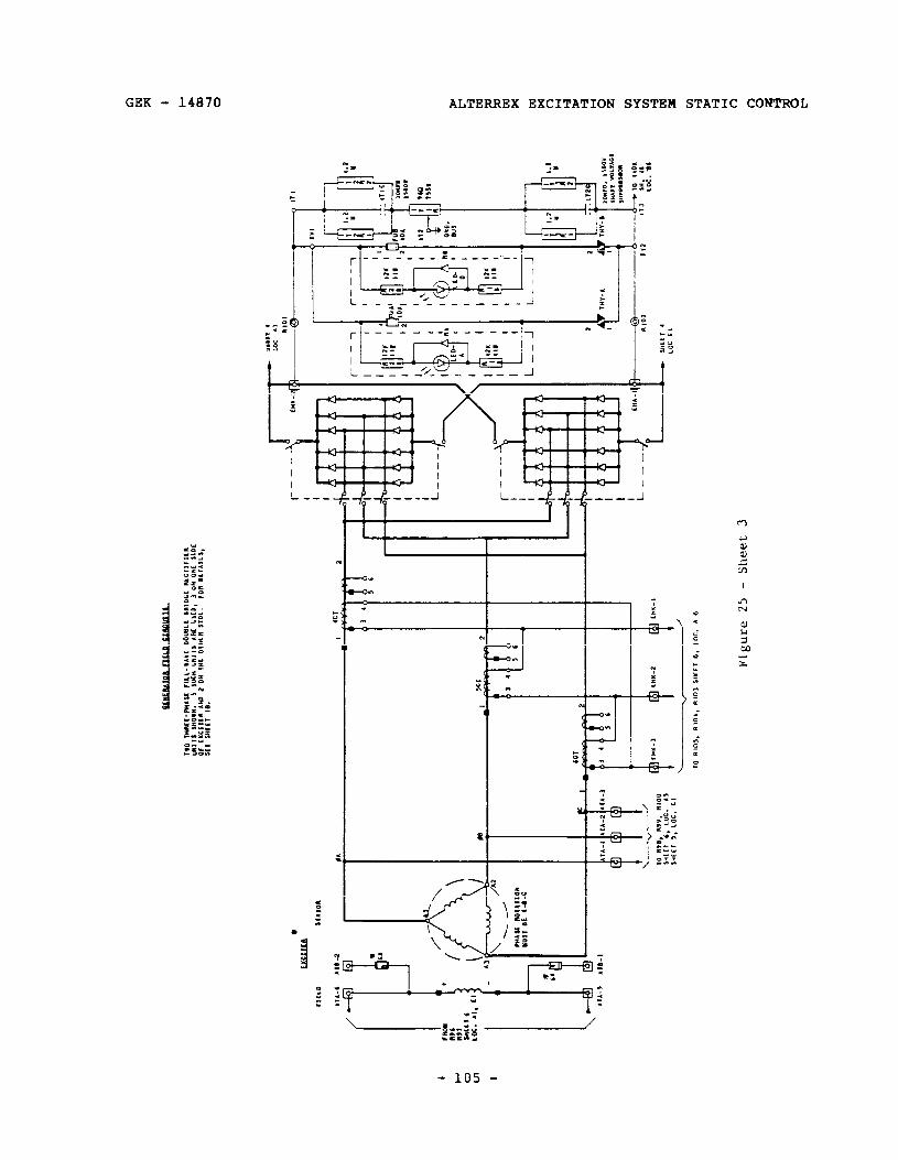
GEK - 14870 ALTERREX EXCITATION SYSTEM STATIC CONTROL
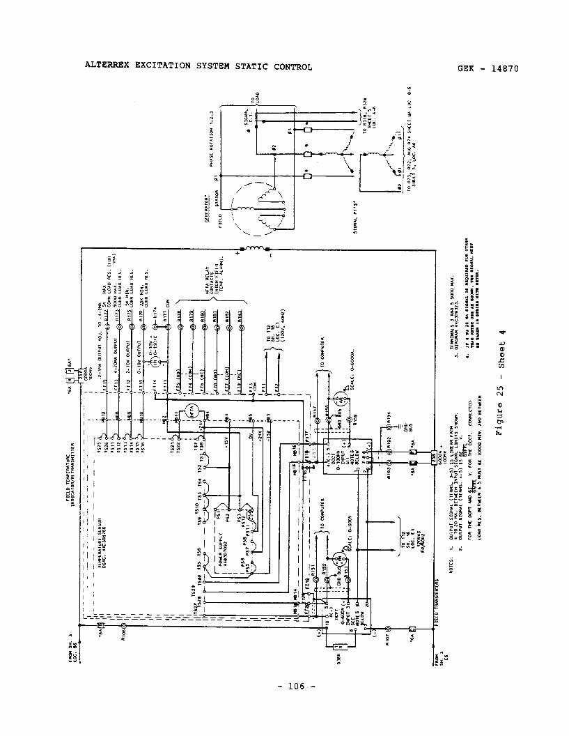
1 ’
ysy .y
’ I
ml*
ml6
m
a --
---_
_ -4
-1-i
SH
. J
6MoA
.
El
IooI
(”
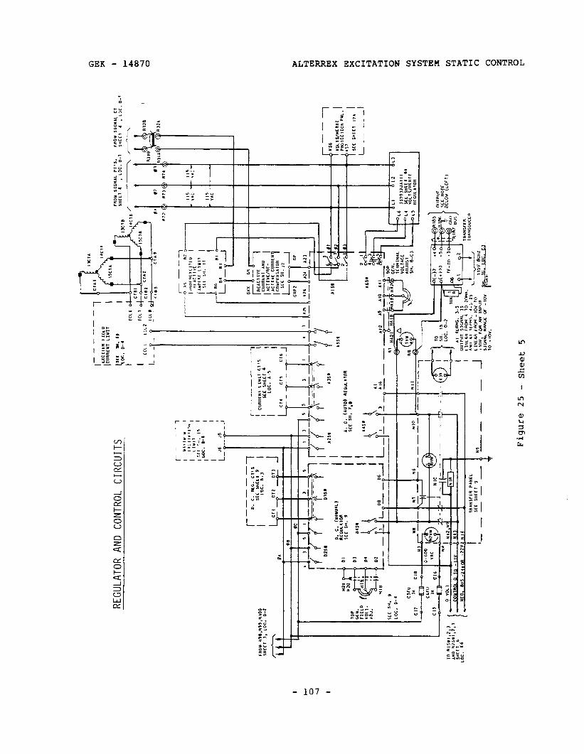
I i
I I
SlIKQ
lI3 lOUNO
CINW HOlWlfI33tl
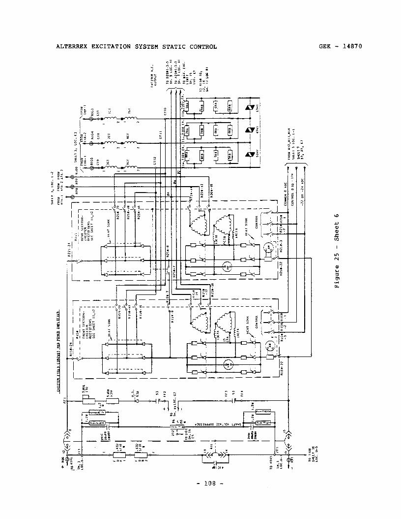
ALTERREX EXCITATION SYSTEM STATIC CONTROL GEK - 14870
- 108 -
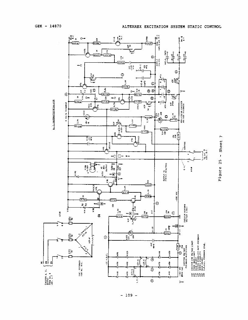
I lil’
4 6
I I
I I
k”Q
Figu
re
25
- Sh
eet
7
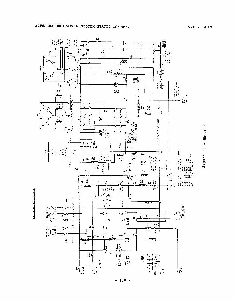
D
Figu
re
25
- Sh
eet
8
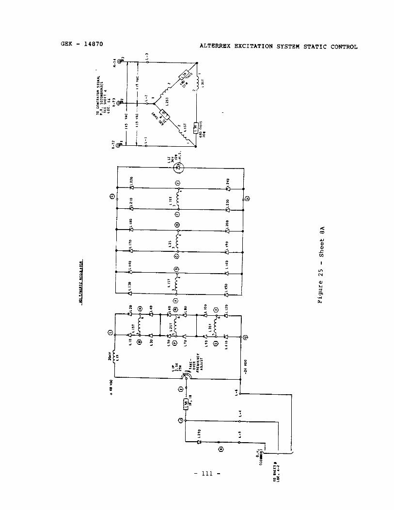
GEK - 14870 ALTERREX EXCITATION SYSTEM STATIC CONTROL
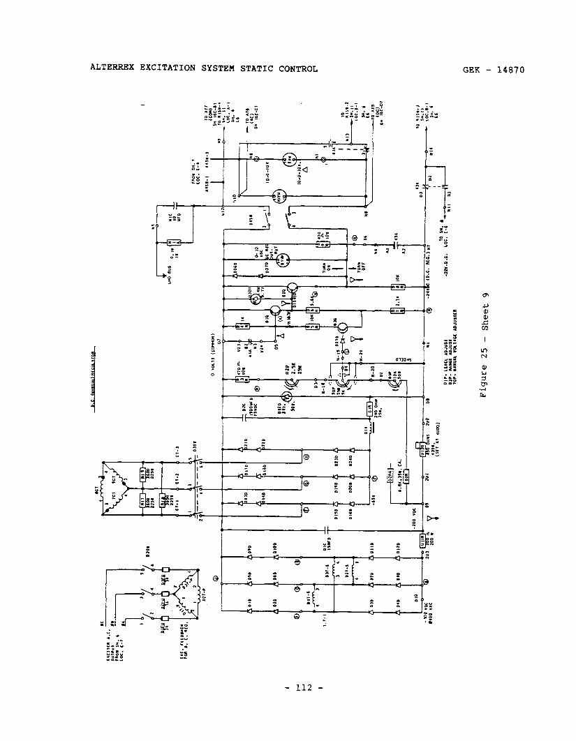
6 7aaqs
- Sz
ambrd
,T(Il _y_- _(!fL __,\
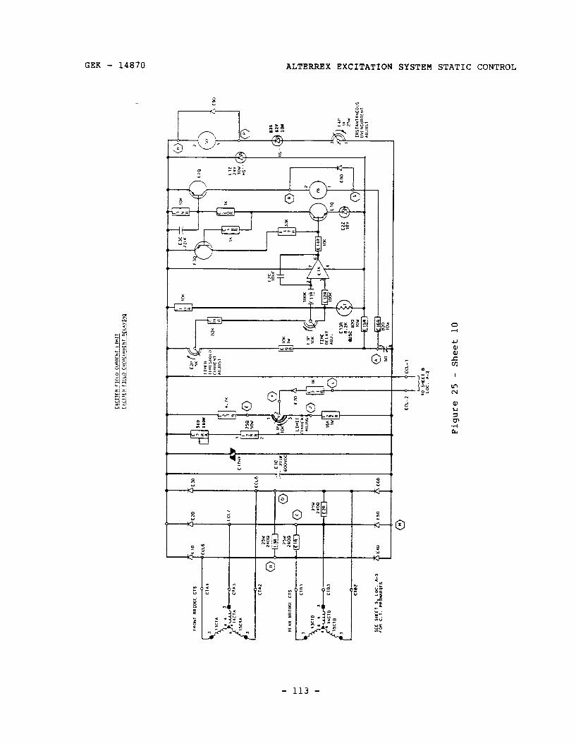
GEK - 14870 ALTERREX EXCITATION SYSTEM STATIC CONTROL

ALTERREX EXCITATION SYSTEM STATIC CONTROL GEK - 14870
L ‘1 :
Y
ii ‘ _ - - _ - _ - - - - - - - _ f
5
2
1 B
4___--_____ i
01 I c--c , Y, “z- P 0 $1 It .
a- I L- ___ _ _ _ ___-__ 1 VI ? ‘:
c I I
= 2 i<
c L ;
- 114 -
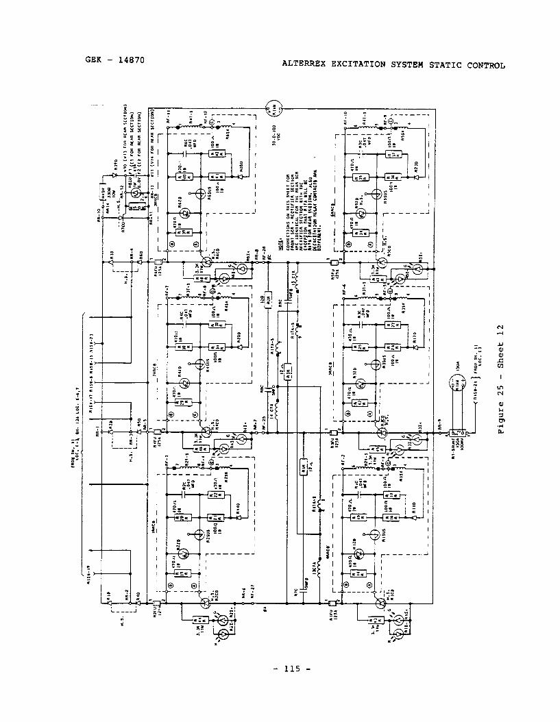
II
I- -
--
Figu
re 25
- Sh
eet
12
r---
!m
CL
- -
- _
_ 1
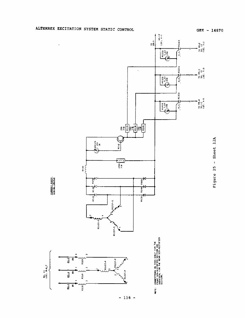
ALTERREX EXCITATION SYSTEM STATIC CONTROL GEK 4870
i - 116 -
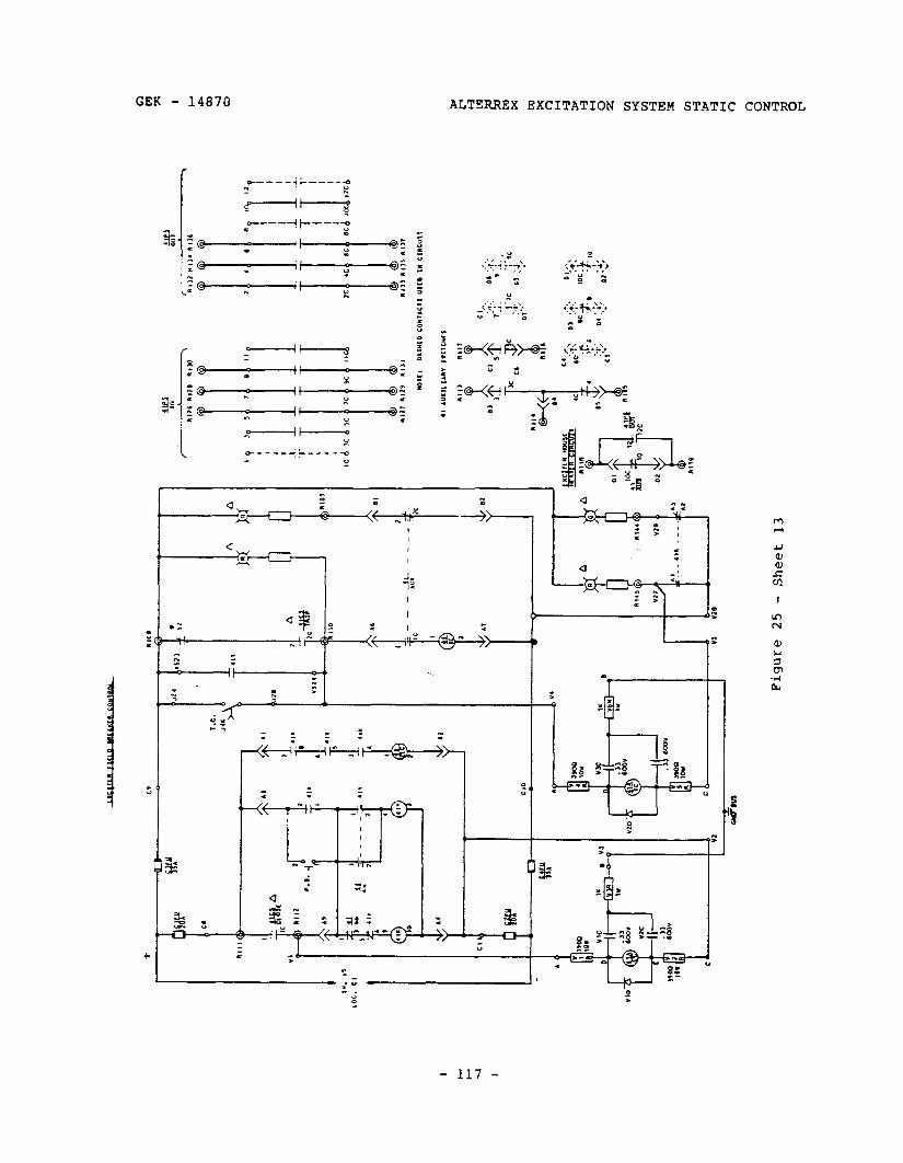
ALTERREX EXCITATION SYSTEM STATIC CONTROL
L n .
:: ; A
- 117 -

ALTERREX EXCITATION SYSTEM STATIC CONTROL GEK - 14870
/ I~:~;;~&1 / I , rr*-ed
l- --_-------__J
X 5 ”
- 118 -
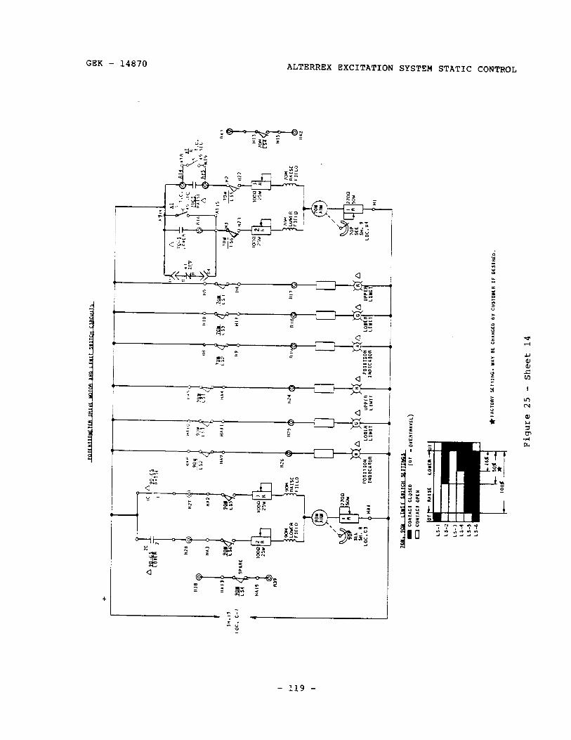
GEK - 14870 ALTERRJZX EXCITATION SYSTEM STATIC CONTROL
- 119 -
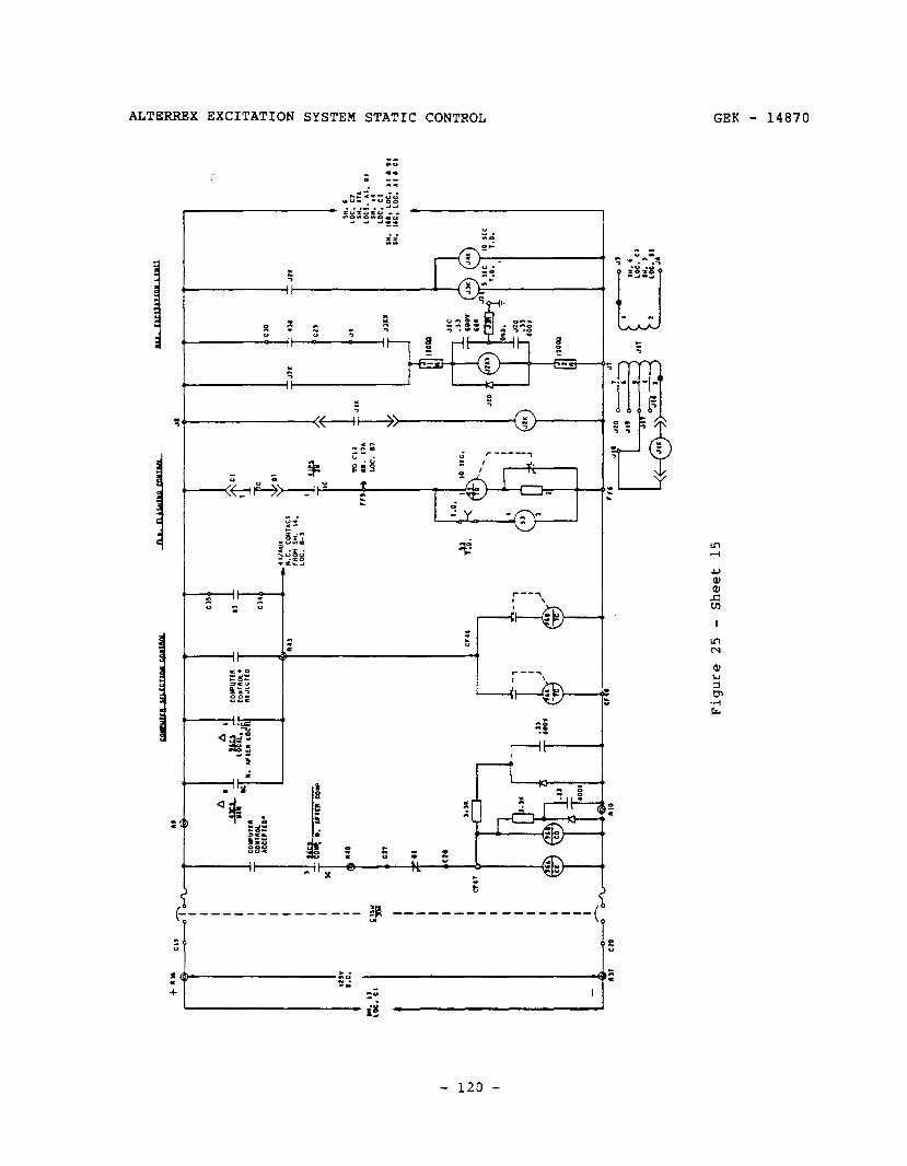
4 Cl0
I 00
Cl,
Jk
1 Ji
ll
,II
140
cll 01
:10
,a>*
,.,I l-i
ii?
j
9‘ co
.a1
600”
“10
-6-’
1 It
om
II tiiT:
JI
G
.a,
‘00”
‘O
R
( )“
I 4
b O”0
. :
JIG
.ll
‘0
0”
I P hl
0 I
1 r -1
e-
1
1 I
.I3
‘00”
‘1
.’
I--JL
C
T
0
Figu
re
25
- Sh
eet
15

GEK - 14870 ALTERREX EXCITATION SYSTEM STATIC CONTROL
- 121 -
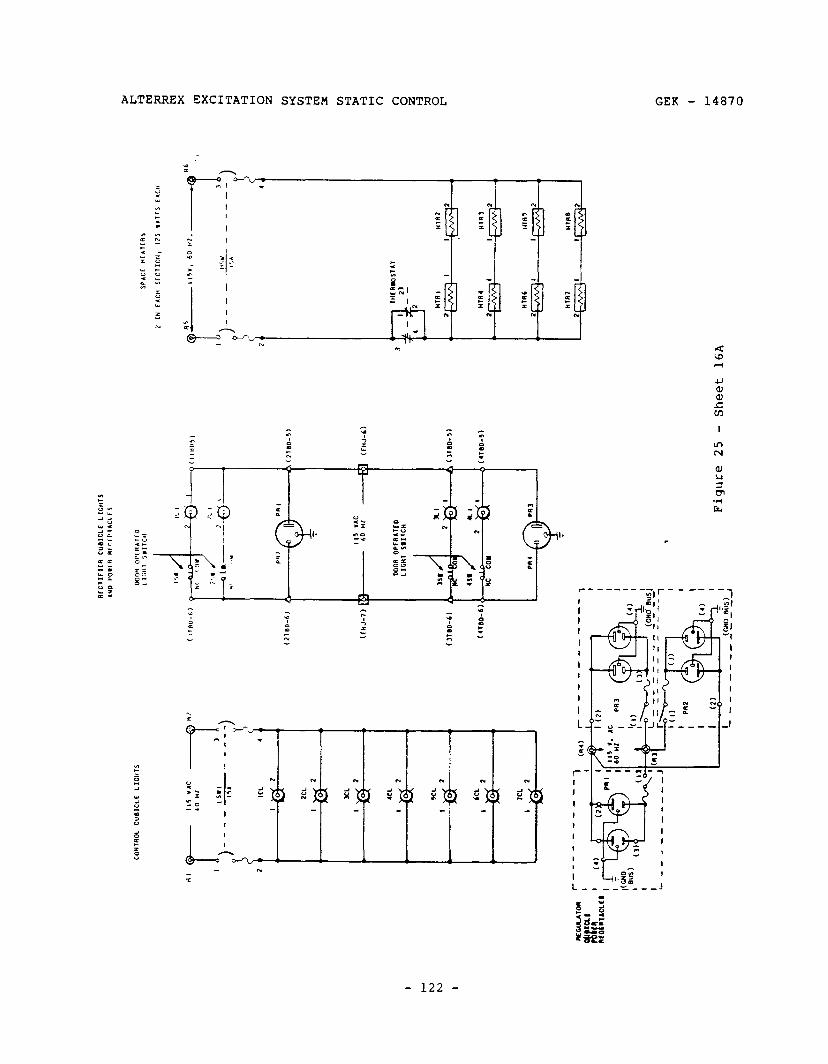
I t- : I
t
. .
n M
c X
L I
._,
2 I
Figu
re
25
- Sh
eet
16~

GEK - 14870 ALTERREX EXCITATION SYSTEM STATIC CONTROL
I _I I 1 3 I
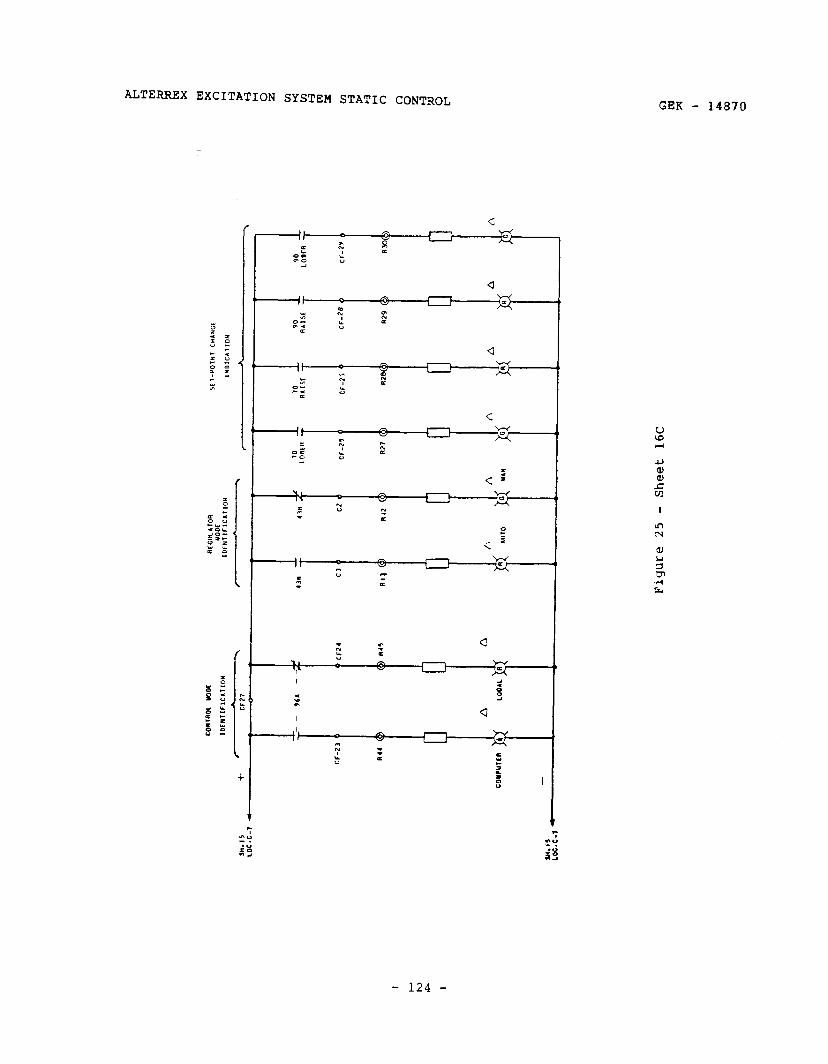
ALTERREX EXCITATION SYSTEM STATIC CONTROL GEK - 14870
V W r-l
- 124 -
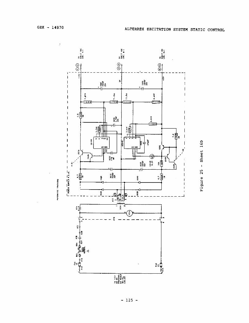
GEK - 14870
:- -I t.
OYY -n_l
ALTERREX EXCITATION SYSTEM STATIC CONTROL
g !. g b Q Q --_ __---------- _--__-_---em d. ------
1
I rrrn
:-- --ax
n
em = - : <
-7 l t
__-_-e--f ----__--- ”
v
f
.
:
z --r 1
a
- 1 9, c-
c
;
- 125 -
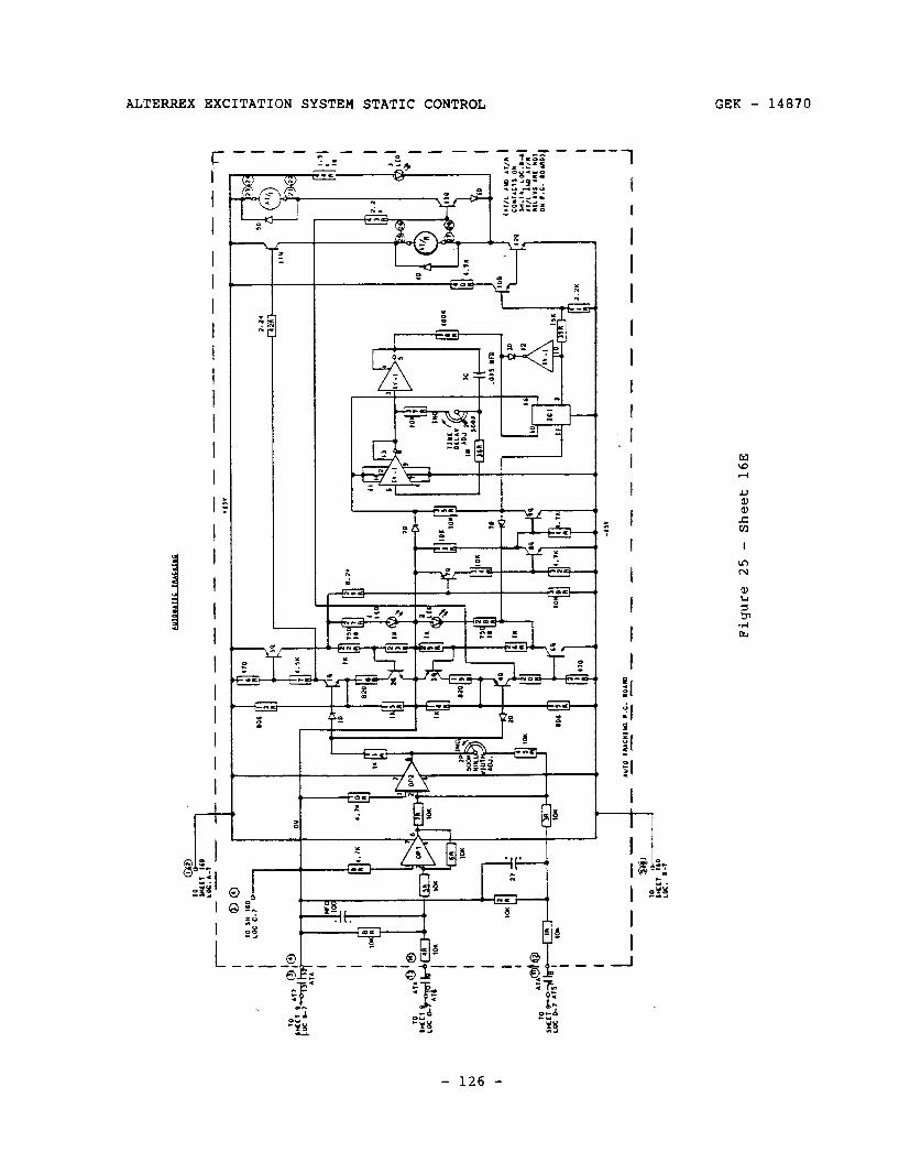
-l-
-,,”
I
L t
L”lO
7a
AC”‘
ul l .C
. .O
AR
--
_--
%J
- -_
____
----
----
--__
___-
Figu
re 25
- S
heet
16
E
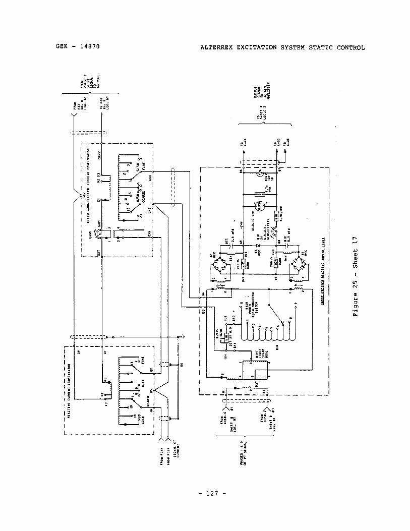
ALTERREX EXCITATION SYSTEM STATIC CONTROL
.
x :A _f za
m--e-
C J ------. - l-4 ---- r- :
ET. o--
---- 1
- 127 -
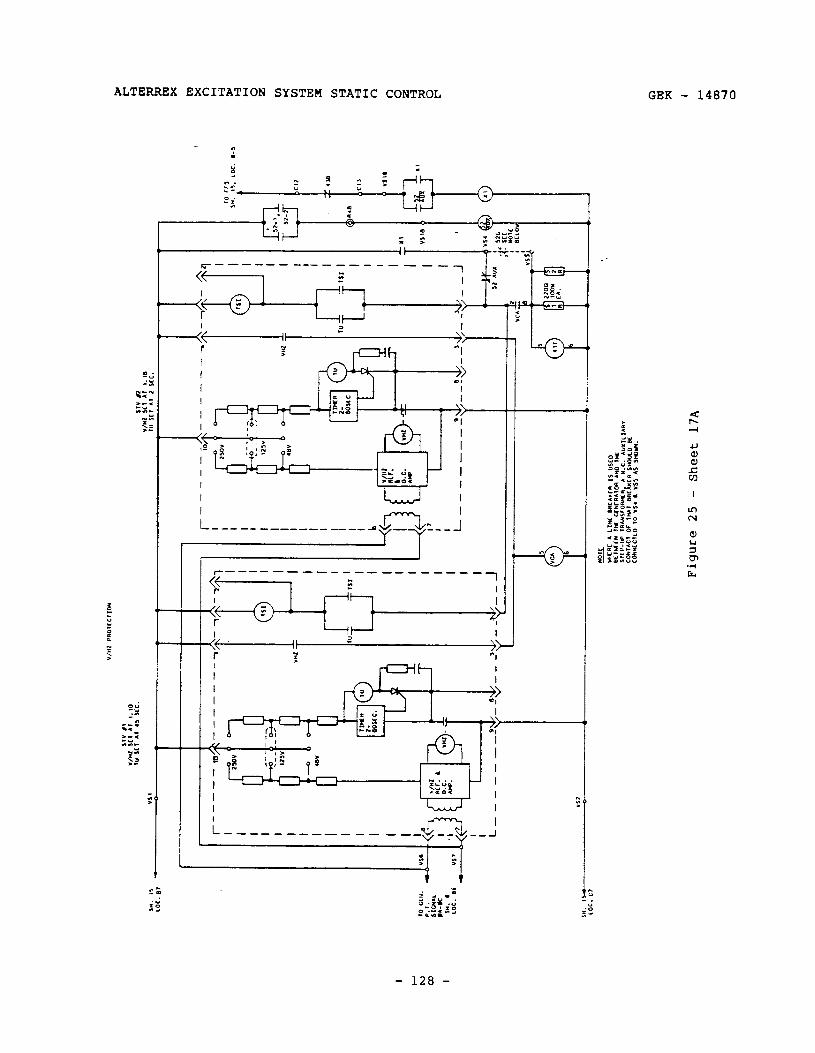
ALTERREX EXCITATION SYSTEM STATIC CONTROL GEK - 14870
. . r
I 4-J 1 I
L________ _______LrL__1 c------___ --------___
F+ {-;2 T 1 ,l II 2 \\ >>-
I- ‘; a 7
-+-
I Ii I=‘“’ I E
I_______-____ _-- g&i 0
- 128 -
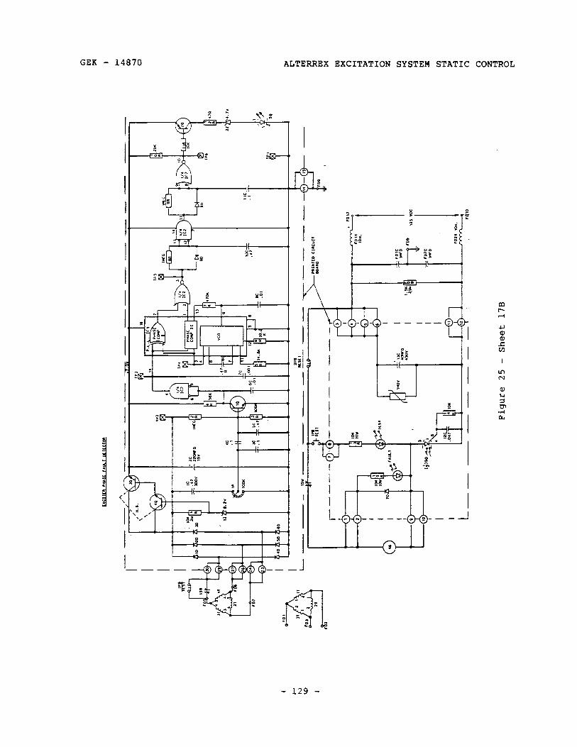
GEK - 14870 ALTERREX EXCITATION SYSTEM STATIC CONTROL
- -----
- 129 -
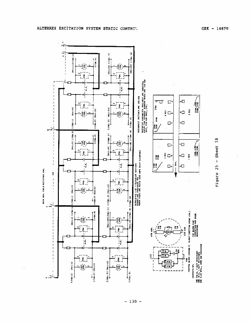
ALTERRJZX EXCITATION SYSTEM STATIC CONTRCT, GEK - 14870
r--
n l-----l_
,z; = .___a
7 *-. _I?: 2 - z;- c ._-
: 2
i :
c ;
q -

GEK - 14870 ALTERREX EXCITATION SYSTEM STATIC CONTROL
f t =.
- 131 -

ALTERREX EXCITATION SYSTEM STATIC CONTROL GEK - 14870
2, II4 1.G. 2 COID.. TWISTED AND SwIELoED
I, tlr OR II6 1.G. 3 COI(D., TlISTED &MD :H~ELDED
I, RO &.G. 3 COYO.. T.lSTED MD SHIELDED
TO SIGN& PT SECOMDARIES tX OR 3 114 AIt CONOS. ‘TRIPLED”)
II, Y. A.C. 60 ML. PREFCRRCD SUPCL" (F)
4ItSmtIP. .I-69,TRIP COnTACTS 9OCS/RrISf, 90-69/RAISE CONTACTS COWON FOR CS COMTICTS 90CS/1_0Xll, PO-69/LO¶Cn CONTACTS ?OC:/?AISC, 70-69/R1ISE CONTACTS 70C:/L07cR, 7049Aom~R CO!ITACTS ~ICS/CLOSE. rr49KLOSE CalTAcTS CO!W'I FOR CO'PUKR Co!,TAC~* ‘XS,I"TO-IFTE? *"IO, 13-69/1UTO CFllTACTS
0 REm.ATOR CUIICLE WKRNIL CO**ECTIONS - *or TO M “AOf I” CUSTOIR
TERYIMAL NOARDS sno.l4 0” THIS S”EET ARE m”*Tfo *!4 RCAR OF RfCULATOR SECTION.
Figure 25 - Sheet 20
- 132 -
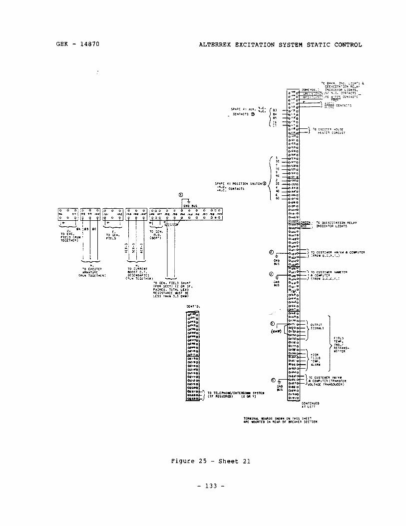
GEK - 14870 ALTERREX EXCITATION SYSTEM STATIC CONTROL
Figure 25 - Sheet 21
- 133 -
ALTERREX EXCITATION SYSTEM STATIC CONTROL GEK - 14870
ADDENDUM #l
This addendum covers some miscellaneous enhancements and options added to the Alterrex system over the last few years.
- 134 -
GEK - 14870 ALTERREX EXCITATION SYSTEM STATIC CONTROL
INITIAL OPERATION CHECKS
licable, should be made The following additional calibrat ion checks, if app during initial operation checkout.
1. The automatic tracking circuit, if supplied, should be checked per the GEK specified. Upon completion of this test, turn off the ATS switch for the remaining checks.
2. The inverse time maximum excitation limit circuit should now be tested per GEK-15014.
3. The Volts/Hertz Regulator, if supplied, should now be checked per GEK specified.
4. Check exciter
This circuit, obsoleted and
field breaker static discharge circuit for AKR breakers.
Figure Al, is necessary because the AKF breaker has been the AKR breaker does not have a reverse acting center pole.
NOTE: The newest Alterrex units use the Drive Systems breaker which has the reversed center pole and does not require this circuit.
Under normal conditions, a high reverse voltage, indicating a breaker trip, activates the detector circuit. The detector circuit then fires an SCR (XlCD) to place the field discharge resistor in the circuit. Also, relay 41D from the breaker circuit will fire the SCR on low voltage trips. Reactor X1X limits peak currents in the SCR. Relay 59DR is a protective device which trips the breaker to protect the FDR if a spurious signal activates the detector circuit.
- 135 -
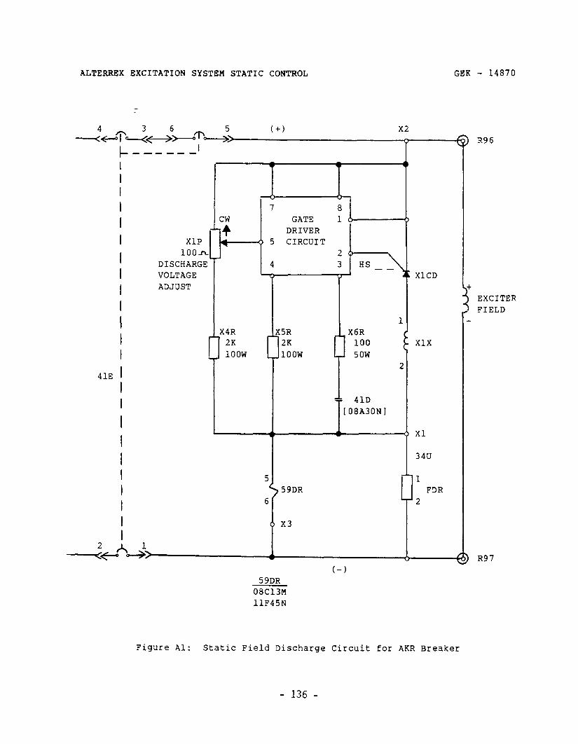
ALTERREX EXCITATION SYSTEM STATIC CONTROL GEK - 14870
I I I I I I I I I I I I I I I I
I I I I
I
I
I
I
41E
XlP 1OOh
DISCHARGE VOLTAGE ADJUST
I-
I X4R
I 2K
1 1oow
DRIVER -0 5 CIRCUIT
2 4 3 HS --
== 41D [08A30N]
. .
1
t-1 59DR
08C13M llF45N
5
i
59DR 6
x3
XlCD
I
1 FDR
2
) R96
) R97
Figure Al: Static Field Discharge Circuit for AKR Breaker
- 136 -
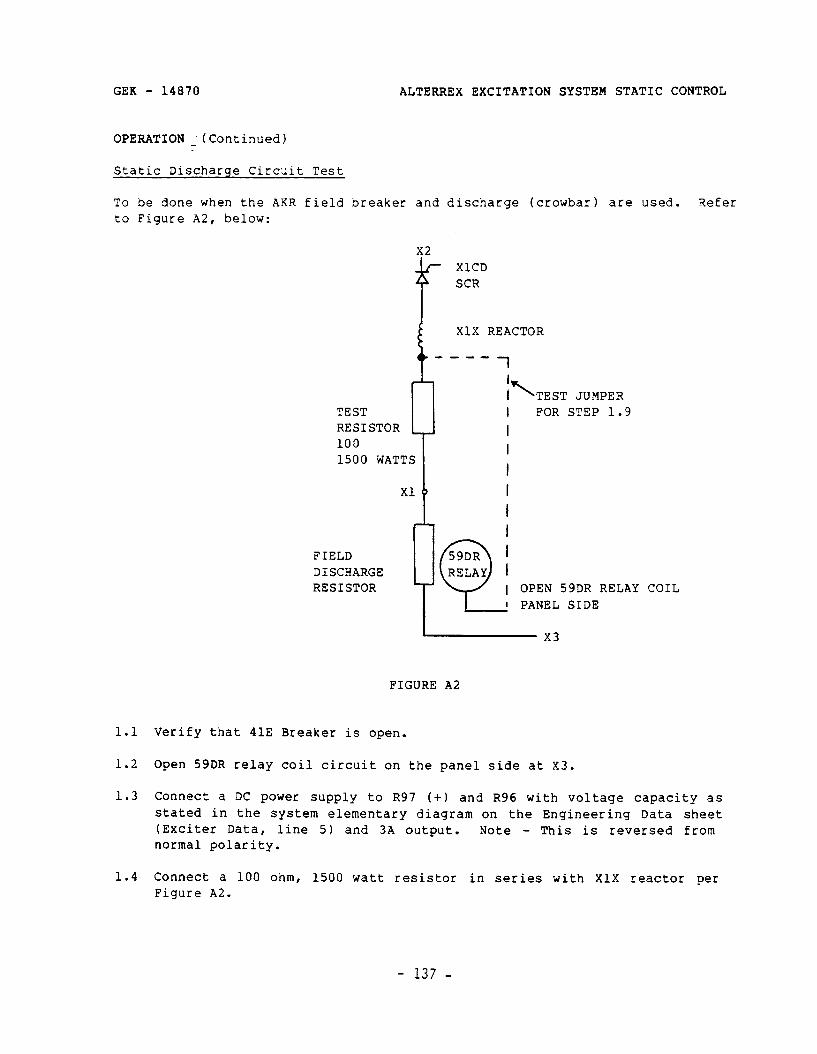
GEK - 14870
OPERATION : (Continued)
ALTERREX EXCITATION SYSTEM STATIC CONTROL
Static Discharge Circuit Test
To be done when the AKR field breaker and discharge (crowbar) are used. Refer to Figure A2, below:
x2
f
XlCD SCR
TEST RESISTOR 100
i
X1X REACTOR
_--- 1
12 TEST JUMPER I FOR STEP 1.9
lJ 1500 WATTS
FIELD DISCHARGE RESISTOR 1 OPEN 59DR RELAY COIL
I PANEL SIDE
FIGURE A2
1.1 Verify that 41E Breaker is open.
1.2 Open 59DR relay coil circuit on the panel side at X3.
1.3 Connect a DC power supply to R97 (+I and R96 with voltage capacity as stated in the system elementary diagram on the Engineering Data sheet (Exciter Data, line 5) and 3A output. Note - This is reversed from normal polarity.
1.4 Connect a 100 ohm, 1500 watt resistor in series with X1X reactor per Figure A2.
- 137 -
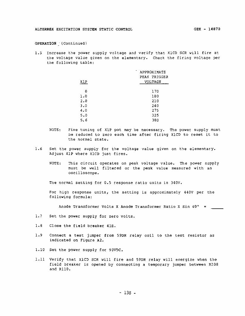
GEK - 14870 ALTERREX EXCITATION SYSTEM STATIC CONTROL
OPERATION _- (Continued)
1.5 Increase the power supply voltage and verify that XlCD SCR will fire at the voltage value given on the elementary. Check the firing voltage per the following table:
1.6 Set the power supply for the voltage value given on the elementary. Adjust XlP where XlCD just fires.
NOTE: This circuit operates on peak voltage value. The power supply must be well filtered or the peak value measured with an oscilloscope.
The normal setting for 0.5 response ratio units is 340V.
For high response units, the setting is approximately 440V per the following formula:
Anode Transformer Volts X Anode Transformer Ratio X Sin 40" =
1.7 Set the power supply for zero volts.
1.8 Close the field breaker 41E.
1.9
1.10
1.11
Connect a test jumper from 59DR relay coil to the test resistor as indicated on Figure A2.
Set the power supply for 9OVDC.
Verify that XlCD SCR will fire and 59DR relay will energize when the field breaker is opened by connecting a temporary jumper between R108 and RllO.
APPROXIMATE PEAK TRIGGER
XlP VOLTAGE
0 170 1.0 180 2.0 210 3.0 240 4.0 275 5.0 325 5.6 380
NOTE: Fine tuning of XlP pot may be necessary. The power supply must be reduced to zero each time after firing XlCD to reset it to the normal state.
- 138 -

GEK - 14870 ALTERREX EXCITATION SYSTEM STATIC CONTROL
OPERATION _ (Continued)
NOTE: Relay 41D should stay picked up for about 1.5 seconds after this jumper is removed.
1.12 Remove all power.
1.13 Disconnect the power supply and test resistor and reconnect the circuit for normal operation.
ALTERREX ENHANCEMENT PER TIL 961-3
IF ENHANCEMENT IS BEING INSTRUCTIONS INCLUDED IN
I ---- ‘ CAUTION 3 -I--
MADE AS A FIELD MODIFICATION, REFER TO THE FACTORY KIT FOR CHECKOUT AND CALIBRATION.
This instruction is for checking calibration of units already equipped with the 44C300339-GO5 AC (AUTOMATIC) Regulator board.
I. Check the following resistance settings for the AC Regulator.
A. On the AC Regulator Board:
1.
2.
3.
Regulator Rate Feedback Resistance
Check resistance of resistor A21R. This should be 4.7K ohms + 5% or 5.1K ohms + 5%. Verify that potentiometer A4P is set such that A4P + A21R equals 63K ohms + 5%. (I.E., if A21R is measured to be 4.7K ohms + 5%, then A4P G set for 58.3K ohms f_ 5%.) It should be noted that one end of resistor A21R terminates at board terminal 20 and one end of potentiometer A4P terminates at terminal 21.
URAL Feedback Resistance
Verify that potentiometer A9P is set for a resistance of 102K ohms + 5%. Note that one end of potentiometer A9P terminates at board terminal 15.
URAL Series Stabilizing Resistance
Verify that potentiometer A7P is set for 0 ohms. It should be noted that one end of potentiometer A7P terminates at board terminal 16. The expected potentiometer dial setting is 12.
- 139 -
ALTERREX EXCITATION SYSTEM STATIC CONTROL GEK - 14870
ALTERREX ENHANCEMENT PER TIL 961-3 (Continued)
4. URAL Gain
Verify that potentiometer A8P is set for a resistance of 2K ohms + 5%. -
B. URAL Sensitivity
Locate potentiometer BlP on the URAL panel. Verify that it is set for a resistance of 5K ohms f. 5%.
II. Check the following capacitances for the AC Regulator.
A. Regulator Rate Feedback Capacitance:
The rate feedback capacitors, A2C, that are located in the AC Regulator panel must be connected to provide a total capacitance of fourteen (14) microfarads.
B. URAL Rate Feedback Capacitance
Locate all the rate feedback capacitors, A6C, on the AC Regulator panel. Verify that they are connected in parallel to provide a total capacitance of 82 microfarads.
C. URAL Series Stabilization
Locate all the URAL series stabilization capacitors, ASC, on the AC Regulator panel and verify that they are connected for a capacitance of 10 microfarads.
III. Checking the AC Regulator Gain Settings with a Simulated PT Voltage
The next step is to set the first and second stage gains with a simulated PT voltage for the AC Regulator. This is done by connecting a 3-phase variac to R72, R73, and R74, and adjusting the output of the variac accurately for the rated generator PT output voltage (usually 100 to 120VAC). Temporarily disconnect outgoing wires to generator PTs to prevent the variac voltage from being applied to the generator PTs. The stage gains will be set by measuring both the stage input and output voltages simultaneously with two high impedance voltmeters. Simultaneous readings are necessary if the variac output voltage is changing. The first stage gain (Kl) is to be set at 2 + 5% volts per volt, using potentiometer A6P. The second stage gain (K2) is to be set at 20 + 5% volts per volt, using potentiometer A3P. The total gain of the two stages (Kl, K2) is equal to 40. The procedure described below is one method of setting the gains of the two stages. In this method, the
- 140 -
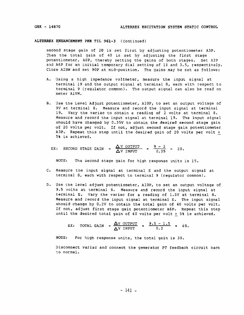
GEK - 14870 ALTERREX EXCITATION SYSTEM STATIC CONTROL
ALTERREX E_NHANCEMENT PER TIL 961-3 (Continued)
second stage gain of 20 is set first by adjusting potentiometer A3P. Then the total gain of 40 is set by adjusting the first stage potentiometer, A6P, thereby setting the gains of both stages. Set A3P and A6P for an initial temporary dial setting of 11 and 3.5, respectively. Close A2SW and set 9OP at mid-position. The gains may be set as follows:
A. Using a high impedance voltmeter, measure the input signal at terminal 19 and the output signal at terminal 8, each with respect to terminal 9 (regulator common). The output signal can also be read on meter AlVM.
B. Use the Level Adjust potentiometer, AlOP, to set an output voltage of 9V at terminal 8. Measure and record the input signal at terminal 19. Vary the variac to obtain a reading of 2 volts at terminal 8. Measure and record the input signal at terminal 19. The input signal should have changed by 0.35V to obtain the desired second stage gain of 20 volts per volt. If not, adjust second stage gain potentiometer A3P. Repeat this step until the desired gain of 20 volts per volt + 5% is achieved.
EX: SECOND STAGE GAIN = Av OUTPUT = 9_2 = Av INPUT 0.35
2. .
NOTE: The second stage gain for high response units is 15.
C. Measure the input signal at terminal E and the output signal at terminal 8, each with respect to terminal 9 (regulator common).
D. Use the level adjust potentiometer, AlOP, to set an output voltage of 9.5 volts at terminal 8. Measure and record the input signal at terminal E. Vary the variac for a reading of 1.5V at terminal 8. Measure and record the input signal at terminal E. The input signal should change by 0.2V to obtain the total gain of 40 volts per volt. If not, adjust first stage gain potentiometer A6P. Repeat this step until the desired total gain of 40 volts per volt + 5% is achieved. -
EX: TOTAL GAIN = Av OUTPUT = 9.5 - 1.5 = AV INPUT 0.2
4. .
NOTE: For high response units, the total gain is 30.
Disconnect variac and connect the generator PT feedback circuit back to normal.
- 141 -
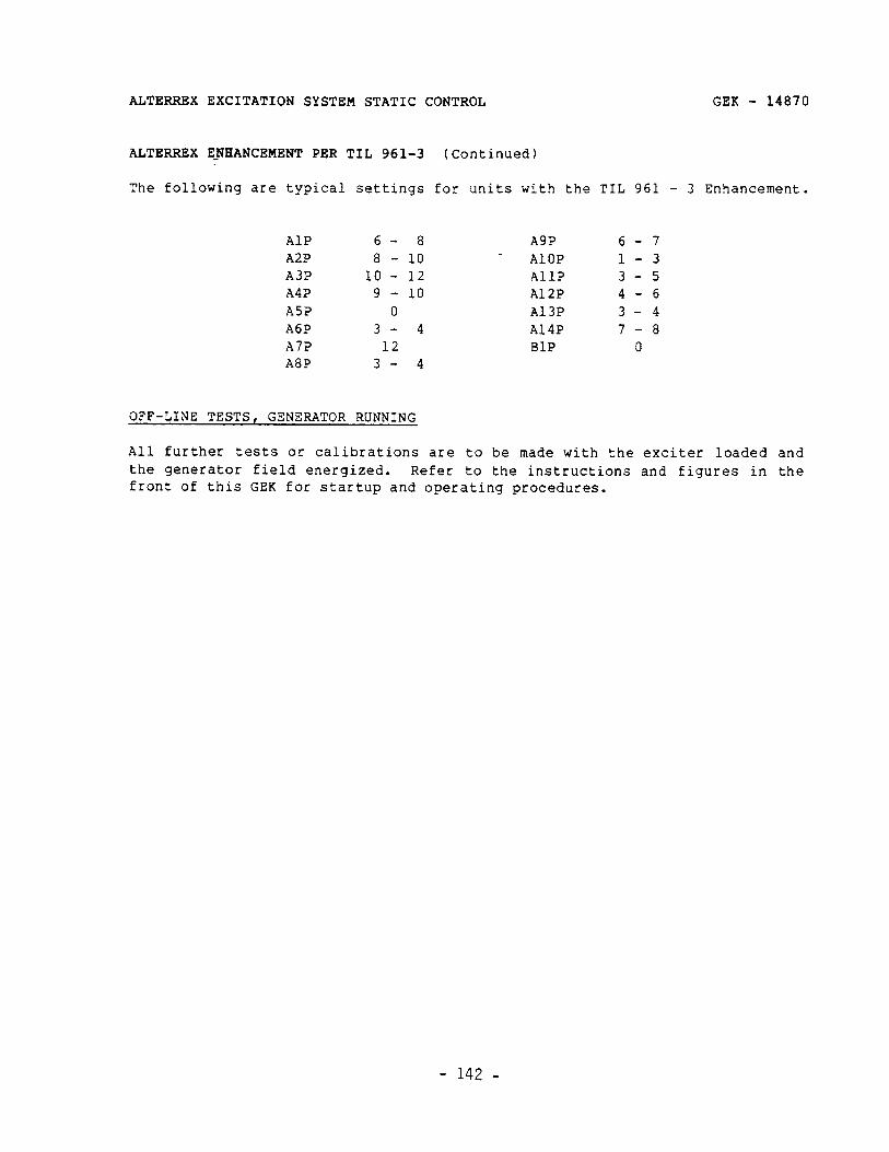
ALTERREX EXCITATION SYSTEM STATIC CONTROL GEK - 14870
ALTERREX EJWANCEMENT PER TIL 961-3 (Continued)
The following are typical settings for units with the TIL 961 - 3 Enhancement.
AlP A2P A3P A4P A5P A6P A7P A8P
6- 8 A9P 6-7 8 - 10 AlOP l-3 10 - 12 AllP 3-5 9 - 10 A12P 4-6 0 A13P 3-4
3- 4 A14P 7-8 12 BlP 0 3- 4
OFF-LINE TESTS, GENERATOR RUNNING
All further tests or calibrations are to be made with the exciter loaded and the generator field energized. Refer to the instructions and figures in the front of this GEK for startup and operating procedures.
- 142 -
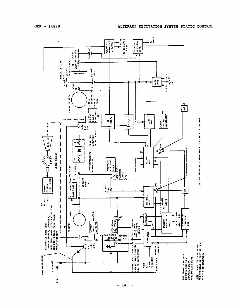
( D
B-B
XC
ITA
TIO
N)
FLA
SH
ING
\ G
ND
DB
T, RB
LAY
, S
K.
PH
AS
B
PA
ULT
D
STB
CTO
R
SP
EE
D
SS
NS
OR
HS
LAY
1
PIL
OT)
f-m.
n O
UTP
UT
TRA
NS
PO
RM
ER
‘IR
IP
GIN
. I
I G
BN
SR
ATO
R
AR
M.
PO
WE
R
SY
STB
M
1
CU
RR
EN
T
BO
OS
T
CT9
I
O”B
”Tl!“
PBR
AT”R
B M
ULT
IPLE
A
LAR
M
CK
TS.
CIR
CU
ITS
1 “T
BRLC
KK
BD
TO
TR
LNS
PB
R
DC
RB
G.
CTS
.
CIR
CU
IT
l-4
I SY
NC
". j?
Y H
+ A
C R
BG
.
1 t
-v--
-l _ r
I U
NS
AL.
DB
TEC
TOR
-.....
. I=
“n
t+
I I r
.
“AXI
NU
”
EXCI
TATI
Ml
I.‘“*
*
I I
TRIP
TR
IP
GB
N
. FX
C.
AlAH
" t
TRIP
TRIP
B
XC
.
GE
N.
AD
DIT
ION
AL
PS
ATU
RB
S:
CO
NTR
OL
SW
ITC
HE
S
CO
NTR
OL
RB
LAY
S
AU
TOM
ATI
ON
R
BLI
YS
E:
SO
MB
P
SA
TUR
BS
S
HO
WN
AR
K
OP
TIO
NA
L O
R
SP
BC
14L.
A
ND
MA
Y
NO
T S
B
IIIC
‘UD
SD
.
ALTERREX EXCITATION SYSTEM STATIC CONTROL
NOTES
GEK - 14870
- 144 -
GEK - 14870 ALTERREX EXCITATION SYSTEM STATIC CONTROL
NOTES
- 145 -
ALTERREX EXCITATION SYSTEM STATIC CONTROL
NOTES
GEK - 14870
- 146 -

GENERAL ELECTRIC COMPANY . DRIVE SYSTEMS OPERATIONS SALEM, VIRGINIA 24153
GENERAL @ ELECTRIC