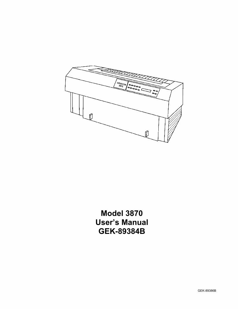
Model 3870 User’s Manual GEK-89384B
124
GEK-89386B Model 3870 User’s Manual GEK-89384B
Transcript of Model 3870 User’s Manual GEK-89384B
GEK-89386B
Model 3870User’s ManualGEK-89384B

ii

iii
iv
FCC Compliance Statement
This equipment generates and uses radio frequency energy and if not installed andused properly, i.e. in strict accordance with the instructions, may cause interference toradio or television reception. It has been tested and found to comply with the limits fora Class B computing device pursuant to Subpart B of Part 15 of FCC Rules, which aredesigned to provide reasonable protection against such interference when operated in aresidential installation.
Instructions to User
If this equipment does cause interference to radio or television reception, which can bedetermined by turning the equipment off and on, the user is encouraged to try tocorrect the interference by one or more of the following measures:
• Reorient the receiving antenna.
• Relocate the equipment with respect to the receiver.
• Move the equipment away from the receiver.
• Plug the equipment into a different outlet so that equipment and receiver are ondifferent branch circuits.
• Ensure that cover mounting screws, attachment connector screws, and groundwires are tightly secured.
• Ensure that the data cable shield is properly grounded at the printer and datasource connectors. If necessary, consult your dealer service representative foradditional suggestions.
The manufacturer is not responsible for any radio or TV interference caused byunauthorized modifications to this equipment. It is the responsibility of the user tocorrect such interferences.
The user may find the following booklet prepared by the Federal CommunicationsCommission helpful: How to Identify and Resolve Radio-TV Interference Problems.
The above booklet is available from the US. Government Printing Office,Washington, DC 20402, Stock No. 004-000-00345-4.

v
SICHERHEITS – ANLEITUNGModelle GENICOM 3870 DA
Das Gerät entspricht der Schutzklasse I und muß immer an eine 3-adrige, geerdeteSteckdose angeschlossen werden. Der Netzan-schluß befindet sich an derDruckerrückwand. Stellen Sie sicher, daß die Netzspannung mit den Angaben auf demTypenschild übereinstimmt.
Einschalten des Druckers :
- Alle Abdeckungen müssen geschlossen sein
- Kaine Gegenstände auf dem Drucker ablegen oder gegen das Gerät lehnen
- Schalten Sie am Netzschalter den Drucker ein (1). Die “Power-Anzeige” leuchtet auf und zeigt damit an, daß der Drucker eingeschaltet ist.
Abschalten:
- Um den Drucker abzuschalten, Schalten Sie am Netzschalter den Drucker aus (0).
A C H T U N GArbeiten und Reparaturen am geöffneten Gerät dürfen nur vom autorisiertenGENICOM – Kundendienst vorgenommen werden.
Bescheinigung des Herstellers/ImporteursHeirmit wird bescheinigt, daß der / die
3870 DA (Gerät, Typ. Bezeichnung)In Übereinstimmung mit Bestimmungen dervfg 1046/1984 (Amtsblattverfügung)funkentstört ist/ sind.Der Deutschen Bundespost wurde das Inverkehrbringen dieses Gerätes angezeigt unddieBerechtigung zur Überprüfung der Serie auf Einhaltung der Bestimmungeneingeräumt.
GENICOM GmbH, Auf der Krautweide 3265812 Bad Sodenl TaunusTel. 0049619665990 Fax 00496196659990
Name des Herstellers / Importeurs
vi
Statement of Compliance
This digital apparatus does not exceed the Class B limits for radio noise emissionsfrom digital apparatus set out in the Radio Interference Regulations of the CanadianDepartment of Communications.
Le presént apparail numérique n’ émet pas de bruits radioéletriques dépassant leslimits applicables aux apparails numériques de la classe B prescrites dans leRéglement aur le brouillage radioélectrique edicteé par le ministère desCommunications du Canada.
External Devices
Connecting any external device to this printer may affect its electrostatic discharge(ESD) performance, or its radio frequency interference (RFI) performance, or both.
Trademark Acknowledgments
All trademarks and registered trademarks are property of their respective holders.
CENTRONICS of GENICOM Corporation. Epson of Epson America, Incorporated
DEC of Digital Equipment Corporation GENICOM of GENICOM Corporation
IBM and Proprinter of International Business Machines Corporation
Patent Information
The design of this equipment is protected by one or more of the following US. patentsand their international equivalents: 4,761, 087; 4,743, 133; 5,066, 153; 4,630, 948;4,468, 140; 4,213, 714; 4,213, 716; 4,368, 993; 4,627, 344; D-294, 038; 4,988, 224;4,806, 036; 4,479, 598; 4,706561; 4,162, 131; 4,333, 398; 4,568, 209; D-272, 741; D-295, 186; 5,037, 222, 4,482, 148; 5,051, 010; 4,487, 515; 5,074, 837; 4,210, 404;4,322, 172; 4,632,582; D-282; D-282, 173; D-315, 169
vii
Code Compliance
Codes and standards the printer conforms to are listed below :
• UL Standard 1950, 3rd Edition
• C-UL C22.2 No. 220
• GS Sign (Safety), international model only)
• FCC Rules, Part 15, Subpart B
• ANSI X3.4-1977 (code set)
• ANSI X3.41-1974 (code extension)
• ANSI X3.64-1979 (additional codes)
• EIA 232C / CCITT V.24 (personality board dependent)
• IEC 950 (EN60950 / 9.88)
• ISO DP 7779-3 / 9 / 82 and ANSI 12.10-1985 (acoustics)
• EN 50082-1 European Immunity
• EN 55022 CISPR-B Radio Frequency Interference
• International units comply with CE Marking directives
Interface Connectors
CAUTION
Interface connectors may exceed class 2 or LPS limits. Appropriate interconnectingcabling in accordance with the NEC shall be used during installation.
viii
Table of contents Page
Chapter 1. Introduction ..................................................................................................... 1-2Chapter 2. Set It Up and Get It Running ........................................................................... 2-1
Choose a Place for the Printer that is : .......................................................................... 2-1Select the Voltage (Models with Voltage Selector Switch) ............................................ 2-2Select the Voltage (Models without Voltage Selector Switch) ....................................... 2-2Power Cords.................................................................................................................. 2-3Plug It In and Turn It On ................................................................................................ 2-4Install the Ribbon........................................................................................................... 2-5Removing the Ribbon.................................................................................................. 2-10Put Paper in the Tractors ............................................................................................ 2-11Load a Form................................................................................................................ 2-14Print a Test Pattern ..................................................................................................... 2-15A Note About Print Head Gap Adjustment .................................................................. 2-17Adjust Top-of-Form ..................................................................................................... 2-17Attach to a Data Source .............................................................................................. 2-18Quick Status ................................................................................................................ 2-19Line Registration on the first form................................................................................ 2-20
Chapter 3. Control Panel .................................................................................................. 3-1Control Panel Keys........................................................................................................ 3-1LCD Menu Map ............................................................................................................. 3-5Select the Emulation ..................................................................................................... 3-7Status Sheet.................................................................................................................. 3-9
Chapter 4. Printed Menu................................................................................................... 4-1The > Arrow Means the Option Is Enabled.................................................................... 4-1Sometimes Values Are Entered .................................................................................... 4-2Access the Printed Menu .............................................................................................. 4-2Margins for Menu Listings ............................................................................................. 4-3FORMER and FIRST .................................................................................................... 4-3Printed Menu Map ......................................................................................................... 4-3Exit the Printed Menu .................................................................................................. 4-12
Chapter 5. Control Panel Lockouts ................................................................................... 5-1Lock the Printer Online.................................................................................................. 5-1Lock the Printed Menu .................................................................................................. 5-3Lock Various Keys......................................................................................................... 5-3
Chapter 6. Formats ........................................................................................................... 6-1What Is A Format ? ....................................................................................................... 6-1Why Use Formats?........................................................................................................ 6-1The Active Format ......................................................................................................... 6-2Stored Formats.............................................................................................................. 6-2Print All Format Information........................................................................................... 6-2Formats Auto-execute on Paper Path Change.............................................................. 6-3
ix
Table of contents Page
Chapter 6. Formats (Continued)Change a Format - Printed Menu .................................................................................. 6-3Save a Format from the Control Panel .......................................................................... 6-4Save a Format from the Host ........................................................................................ 6-4Select a Format from the Control Panel ........................................................................ 6-4Select a Format from the Host....................................................................................... 6-4Select the Assigned Format from the Host .................................................................... 6-5Power Up to the Currently Assigned Format ................................................................. 6-5Rename a Format ......................................................................................................... 6-5LCD Message Display................................................................................................... 6-5Linking Emulations to Formats ...................................................................................... 6-6
Chapter 7. LCD Head Gap Menu...................................................................................... 7-1Change Ribbon ............................................................................................................. 7-2Pros and Cons of Auto Head Gap Adjust ...................................................................... 7-2Semiautomatic Head Gap Adjust .................................................................................. 7-5
Chapter 8. Line Up the Job on the Page........................................................................... 8-1Vertical Paper Movement .............................................................................................. 8-1What is a Print Reference?............................................................................................ 8-2Set a Top Print Reference............................................................................................. 8-2Set the Tear Off Distance.............................................................................................. 8-3Set a Left Print Reference ............................................................................................. 8-3Local Margins are Tricky ............................................................................................... 8-4Use Top Print Reference or Top Margin?...................................................................... 8-4Use Left Print Reference or Left Margin? ...................................................................... 8-5Load Length Adjustment ............................................................................................... 8-5
Chapter 9. Power Up and Reset ....................................................................................... 9-1The State of the Printer on Power-up ............................................................................ 9-1Reset the Printer - ISU .................................................................................................. 9-1After a Software Upgrade.............................................................................................. 9-2After an ISU................................................................................................................... 9-2
Chapter 10. Paper Handling Features and Techniques .................................................. 10-1Adjust Paper Tension .................................................................................................. 10-2Install the Front Tractors.............................................................................................. 10-4Switch Between Front Feed and Bottom Feed............................................................ 10-6Removing the Rear Tractors ....................................................................................... 10-7Change Paper Paths from the Control Panel .............................................................. 10-9Change Paper Paths from the Host........................................................................... 10-10Recover from a Remote Path Change Failure........................................................... 10-10Auto Load on Paper Out............................................................................................ 10-11Multipart Forms ......................................................................................................... 10-11Manual Paper Path.................................................................................................... 10-12
x
Table of contents Page
Chapter 10. Paper Handling Features and Techniques (Continued)Manual Path Auto-loads the Next Sheet ................................................................... 10-14Continuous Envelopes .............................................................................................. 10-15Clean Up After Nonbonded Paper............................................................................. 10-15Tips for Continuous Forms ........................................................................................ 10-16
Chapter 11. Maintenance and Troubleshooting .............................................................. 11-1Clean the Printer ......................................................................................................... 11-1Troubleshooting........................................................................................................... 11-3Hex Dump ................................................................................................................... 11-5Serial Interface Loopback Test.................................................................................... 11-6Replacing the Print Head ............................................................................................ 11-6Adjust the Flight-Time Compensation ......................................................................... 11-9
Chapter 12. Interface ...................................................................................................... 12-1RS-232C Serial Interface ............................................................................................ 12-1Serial Data Cable ........................................................................................................ 12-4
Serial Pin Assignments............................................................................................ 12-4CENTRONICS Parallel Interface................................................................................. 12-5Parallel Interface Signals............................................................................................. 12-5Parallel Timing Diagram .............................................................................................. 12-6Parallel Data Cable ..................................................................................................... 12-7Buffer Options ............................................................................................................. 12-8
Appendix A. Emulation and Software Options .................................................................A-1Emulation Options .........................................................................................................A-2Software Options...........................................................................................................A-4
Appendix B. Hardware Configuration Menu.....................................................................B-1Appendix C. Options and Supplies ..................................................................................C-1Appendix D. Specifications ..............................................................................................D-1
Paper Handling..............................................................................................................D-2Printer Emulations .........................................................................................................D-2Print Technology ...........................................................................................................D-3Form Control .................................................................................................................D-4
Complete Index.......................................................................................................... Index-1
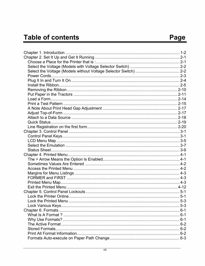
Introduction 1-1
3870 User’s Manual1-2
Chapter 1. Introduction
This printer is a high duty cycle, serial dot matrix printer with a dual paper path andauto print head gap adjustment.
• Among the advanced features of this printer are: automatic or semiautomatic printhead gap adjustment, remote or local selection of emulations, remote or localselection of paper paths, automatic loading of a second paper path when the firstpath is empty, and the ability to store, for subsequent recall, four user-defined setsof parameters called formats. Other characteristics are :
• input voltage: switch-selectable 115 or 230 VAC
• power dissipation: 130 watts maximum
• hardware interfaces: menu selectable CENTRONICS parallel and RS-232serial; and, by adapters: 10 Base T, Token
• standard emulations: menu-or host-selectable ANSI X3.64, IBMGP, IBMProprinter XL, DEC LA-210, Epson FX 286e, and GENICOM 3410.
• standard fonts: menu-or host-selectable Gothic, Gothic Italic, Micro Gothic,Wide Gothic, Courier, and Courier Italic, OCR-A, OCR-B, Oversize in Draftor Near Letter quality, each; in pitches of 10, 12, 13, 15, 16, 17, 17.1, 20.
• ANSI Oversized: rotatable, expandable to 18700 points in 10-point increments.See Oversized Font chapter in Programmer’s Manual.
• ANSI bar codes: Twenty-four styles, rotatable and scaleable. See Bar Codechapter in Programmer’s Manual.
NOTE: Complete specifications are in Appendix D.
Set It Up and Get It Running 2-1
Chapter 2. Set It Up and Get It RunningPackaged with the printer and this manual are a power cord, a ribbon cartridge, atractor assembly, and a programmer’s manual.
Choose a Place for the Printer that is :
level and solid Print head speeds are very high. If the printer table is not extremelystable, the printer may cause the printer table to rock.
away from direct sunlight Ribbon inks dry out in the sun.
away from heaters andheating vents
High temperatures degrade plastic and stress electrical components,and provokes thermal throttle.
away from excessivedust or moisture
Dust shortens print head and gear train life. Very high humiditycauses paper handling problems.
within 6.5 feet of agrounded AC outlet
The length of the power cord.
suitable for using thebottom paper path ...
The printer stand must have a slot through which to feed paper. Asuitable pedestal is available from an authorized dealer. See “PaperHandling Features and Techniques”, Chapter 10. The bottom paperpath is the best choice for gummed labels, bar codes, multipartforms, and other hard-to-feed stock.
away from conferencerooms & their door-ways
Sound emission at 10 ft can be high even with all damping plastic inplace and printer operating with top and/or front doors open or coverpanels removed. Noise is a workplace stress factor.
away from critically dust-sensitive operations
All paper is a source for dust. Printhead wires create more of thisdust. Higher printer use with economy papers can create high enoughdust levels to aggravate asthma or contaminate sensitive processes.Never put any printer in a “clean room”.

3870 User’s Manual2-2
Select the Voltage (Models with Voltage Selector Switch)
CAUTION: Do not select115V and plug theprinter into 230V !
If the printer is plugged into 230V when set to 115V and power isapplied, the power supply will be seriously damaged. On the otherhand, if 230V is selected and the printer is plugged into 115V, it willnot be damaged, but the printer won’t work.
Check the voltageselector switch on theback of the printer.
Printers shipped to the US. and to Canada have the switch set to115V. Printers shipped to other countries are shipped with the switchset to 230V. Either 115V or 230V will be visible in the windows onthe switch. Most installations in the US. use 115V.
If you need to changevoltage ...
Use a slender object such as a paper clip that has been straightened.When setting the printer for 115 VAC, slide the switch to the left soit shows 115V. Slide it to the right for 230V operation.
Select the Voltage (Models without Voltage Selector Switch)
If there is No VoltageSelector……
Printers without a Voltage Selector Switch will automatically switch tothe correct voltage setting. No additional action is necessary by theuser.
Set It Up and Get It Running 2-3
Power Cords
Don't use two-wire extension cords or adapters that allow connection to ungroundedoutlets.
A 6.5-foot power cord is shipped with the printer. The power cord included withprinters sold for 115V installations in the US. and Canada is ready to use.International model printers are shipped with a power cord which can be used in anumber of European countries.
For units to be operated at 115V, use a UL Listed/ CSA Certified three-conductor cordset, #18 AWG minimum, Type SVT or SJT. The maximum length is 15 feet. Theremust be a NENIA 5-15P (parallel blade, grounding type) plug on one end and aCEE 22/5 socket on the other end. The cord set should be rated 10A, 250V and have agrounding plug with safety approvals appropriate for the country in which theequipment will be installed.
For units to be operated at 230V inside US. and Canada, use a UL Listed/CSACertified three-conductor cord set, #18 AWG minimum, Type SVT or SJT. Themaximum length is 15 feet. There must be a NEMA 6-15P (tandem blade, groundingtype) plug on one end and a CEE 22/5 socket on the other end. The cord set should berated IOA, 25OV and have a grounding plug with safety approvals appropriate for thecountry in which the equipment will be installed.
For units to be operated at 23OV outside the US. and Canada, use a three-conductorcord set, EUR-H05VV-FG31,0 minimum, with a CEE 22/5 socket on one end. Thecord set should be rated 10A, 250V and have a grounding plug with safety approvalsappropriate for the country in which the equipment will be installed. The cord setshould be marked HAR.
3870 User’s Manual2-4
Plug It In and Turn It On
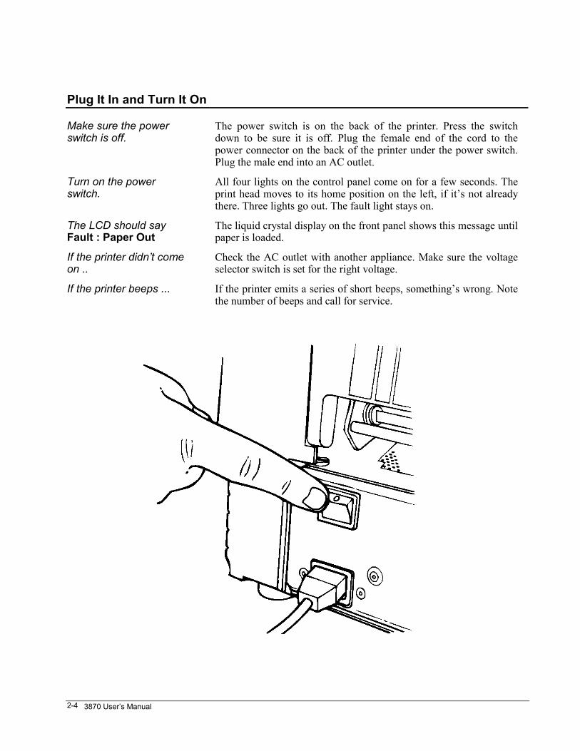
Make sure the powerswitch is off.
The power switch is on the back of the printer. Press the switchdown to be sure it is off. Plug the female end of the cord to thepower connector on the back of the printer under the power switch.Plug the male end into an AC outlet.
Turn on the powerswitch.
All four lights on the control panel come on for a few seconds. Theprint head moves to its home position on the left, if it’s not alreadythere. Three lights go out. The fault light stays on.
The LCD should sayFault : Paper Out
The liquid crystal display on the front panel shows this message untilpaper is loaded.
If the printer didn’t comeon ..
Check the AC outlet with another appliance. Make sure the voltageselector switch is set for the right voltage.
If the printer beeps ... If the printer emits a series of short beeps, something’s wrong. Notethe number of beeps and call for service.
Set It Up and Get It Running 2-5
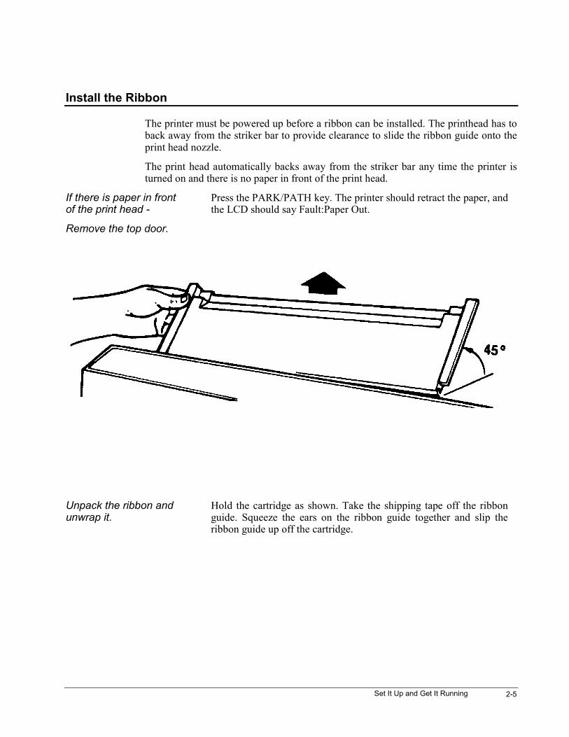
Install the Ribbon
The printer must be powered up before a ribbon can be installed. The printhead has toback away from the striker bar to provide clearance to slide the ribbon guide onto theprint head nozzle.
The print head automatically backs away from the striker bar any time the printer isturned on and there is no paper in front of the print head.
If there is paper in frontof the print head -
Press the PARK/PATH key. The printer should retract the paper, andthe LCD should say Fault:Paper Out.
Remove the top door.
Unpack the ribbon andunwrap it.
Hold the cartridge as shown. Take the shipping tape off the ribbonguide. Squeeze the ears on the ribbon guide together and slip theribbon guide up off the cartridge.
3870 User’s Manual2-6
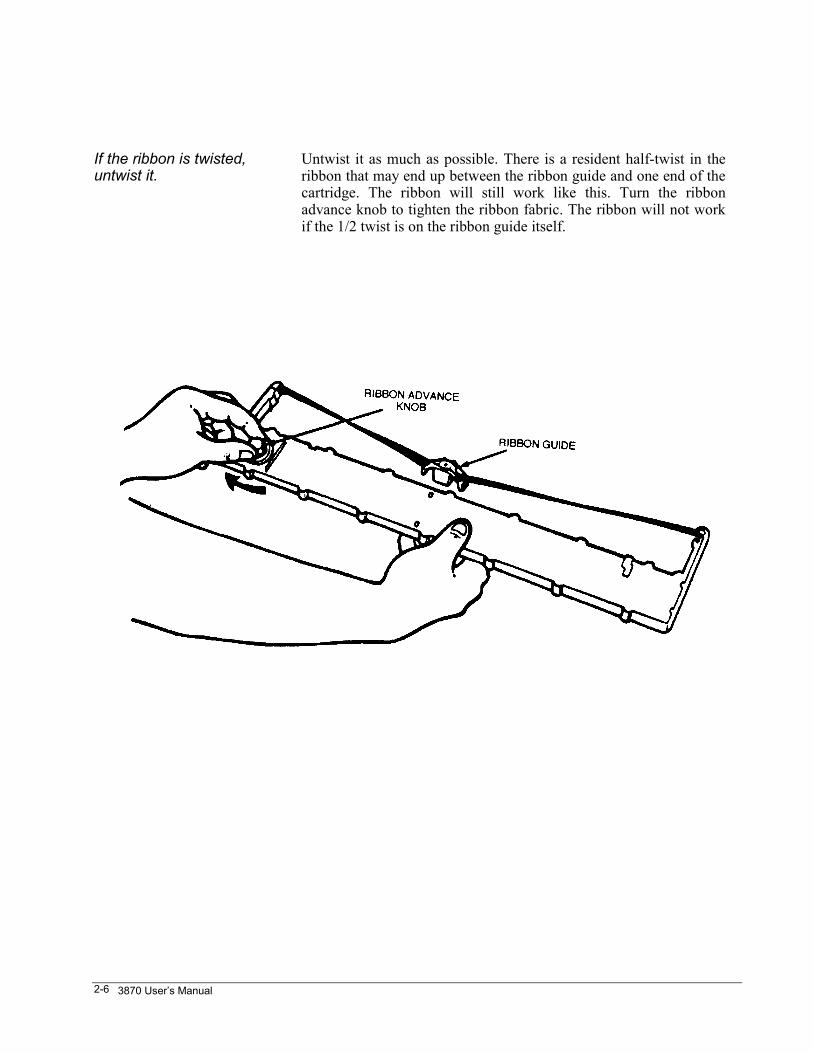
If the ribbon is twisted,untwist it.
Untwist it as much as possible. There is a resident half-twist in theribbon that may end up between the ribbon guide and one end of thecartridge. The ribbon will still work like this. Turn the ribbonadvance knob to tighten the ribbon fabric. The ribbon will not workif the 1/2 twist is on the ribbon guide itself.
Set It Up and Get It Running 2-7
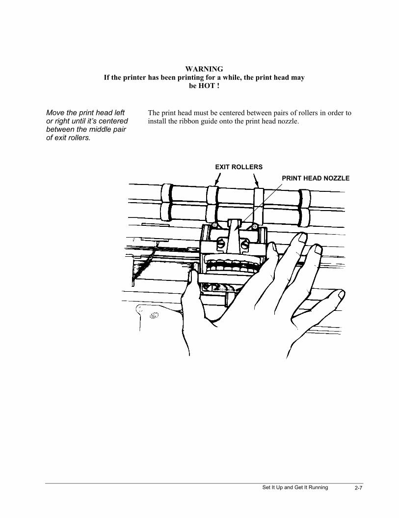
WARNINGIf the printer has been printing for a while, the print head may
be HOT !
Move the print head leftor right until it’s centeredbetween the middle pairof exit rollers.
The print head must be centered between pairs of rollers in order toinstall the ribbon guide onto the print head nozzle.
EXIT ROLLERSPRINT HEAD NOZZLE
3870 User’s Manual2-8
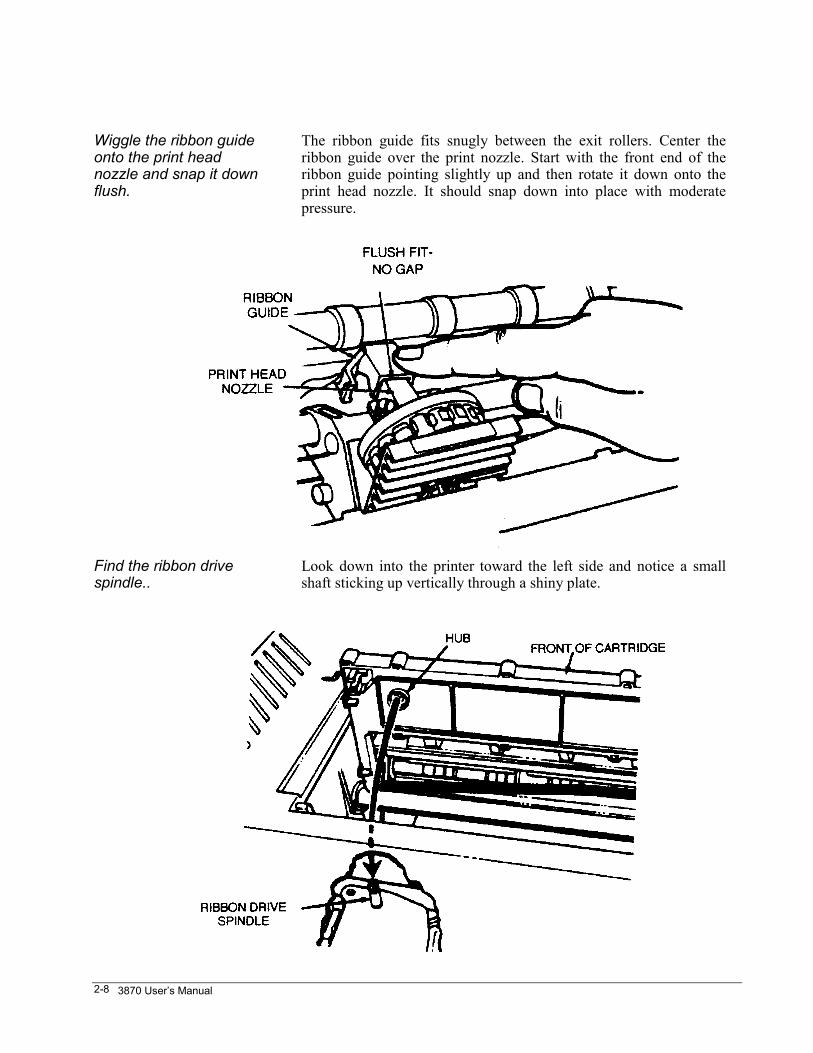
Wiggle the ribbon guideonto the print headnozzle and snap it downflush.
The ribbon guide fits snugly between the exit rollers. Center theribbon guide over the print nozzle. Start with the front end of theribbon guide pointing slightly up and then rotate it down onto theprint head nozzle. It should snap down into place with moderatepressure.
Find the ribbon drivespindle..
Look down into the printer toward the left side and notice a smallshaft sticking up vertically through a shiny plate.
Set It Up and Get It Running 2-9
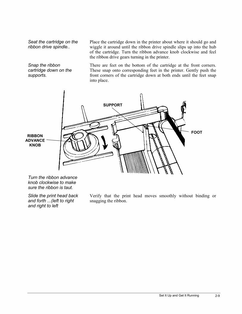
Seat the cartridge on theribbon drive spindle..
Place the cartridge down in the printer about where it should go andwiggle it around until the ribbon drive spindle slips up into the hubof the cartridge. Turn the ribbon advance knob clockwise and feelthe ribbon drive gears turning in the printer.
Snap the ribboncartridge down on thesupports.
There are feet on the bottom of the cartridge at the front corners.These snap onto corresponding feet in the printer. Gently push thefront corners of the cartridge down at both ends until the feet snapinto place.
Turn the ribbon advanceknob clockwise to makesure the ribbon is taut.
Slide the print head backand forth ...(left to rightand right to left
Verify that the print head moves smoothly without binding orsnagging the ribbon.
RIBBONADVANCE
KNOB
SUPPORT
FOOT
3870 User’s Manual2-10
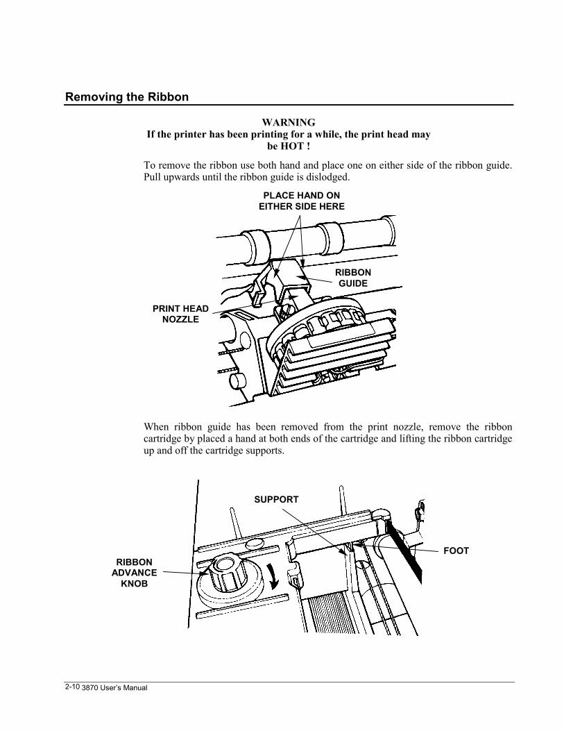
Removing the Ribbon
WARNINGIf the printer has been printing for a while, the print head may
be HOT !
To remove the ribbon use both hand and place one on either side of the ribbon guide.Pull upwards until the ribbon guide is dislodged.
When ribbon guide has been removed from the print nozzle, remove the ribboncartridge by placed a hand at both ends of the cartridge and lifting the ribbon cartridgeup and off the cartridge supports.
PLACE HAND ONEITHER SIDE HERE
RIBBONGUIDE
PRINT HEADNOZZLE
RIBBONADVANCE
KNOB
SUPPORT
FOOT
Set It Up and Get It Running 2-11
Put Paper in the Tractors
Each printer is shipped with a set of tractors installed in the rear. A second set oftractors is packed in a box for installation in the front/bottom paper path – see “Installthe Front Tractors”, in Chapter 10. The procedure for loading sprocket-feed paper isthe same for the rear, front, or bottom paper paths.
The tractor that holds the left edge of the paper will be referred to as the home-position tractor. The other tractor will be called the far tractor.
The factory final test used 14-inch wide paper. To run narrower paper the far tractormust be moved.
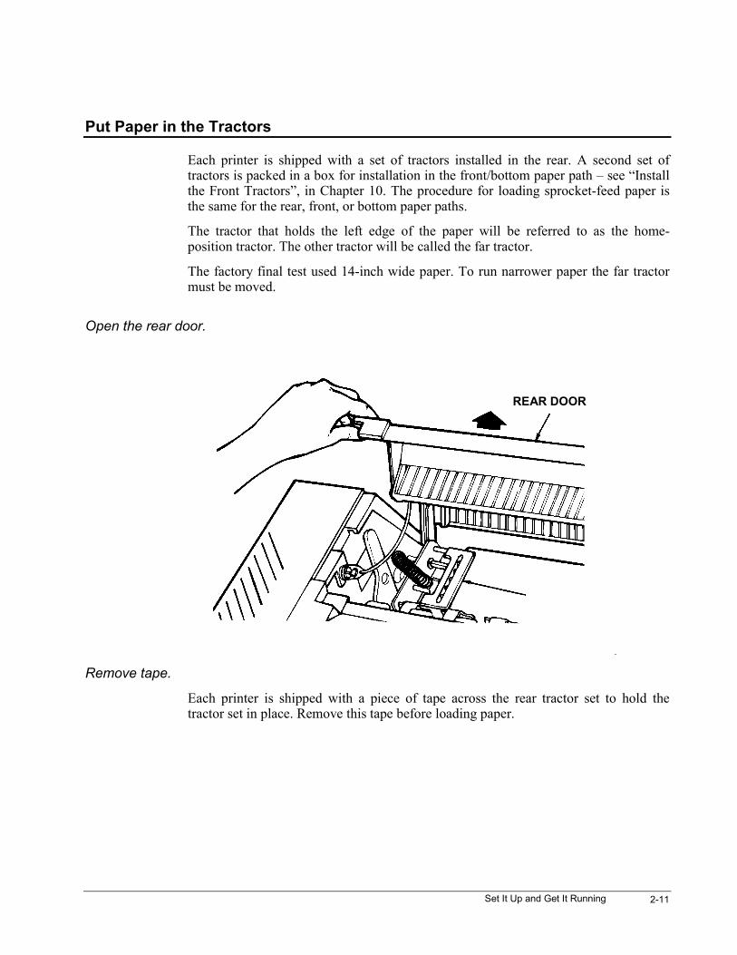
Open the rear door.
Remove tape.
Each printer is shipped with a piece of tape across the rear tractor set to hold thetractor set in place. Remove this tape before loading paper.
REAR DOOR
3870 User’s Manual2-12
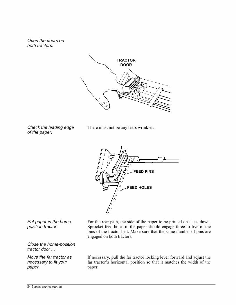
Open the doors onboth tractors.
Check the leading edgeof the paper.
There must not be any tears wrinkles.
Put paper in the homeposition tractor.
For the rear path, the side of the paper to be printed on faces down.Sprocket-feed holes in the paper should engage three to five of thepins of the tractor belt. Make sure that the same number of pins areengaged on both tractors.
Close the home-positiontractor door ...
Move the far tractor asnecessary to fit yourpaper.
If necessary, pull the far tractor locking lever forward and adjust thefar tractor’s horizontal position so that it matches the width of thepaper.
TRACTORDOOR
FEED PINS
FEED HOLES
Set It Up and Get It Running 2-13
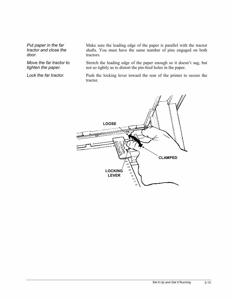
Put paper in the fartractor and close thedoor.
Make sure the leading edge of the paper is parallel with the tractorshafts. You must have the same number of pins engaged on bothtractors.
Move the far tractor totighten the paper.
Stretch the leading edge of the paper enough so it doesn’t sag, butnot so tightly as to distort the pin-feed holes in the paper.
Lock the far tractor. Push the locking lever toward the rear of the printer to secure thetractor.
LOOSE
CLAMPED
LOCKINGLEVER
3870 User’s Manual2-14
Load a Form
Close the Top Cover
If the LCD says
L O C K E D See “Control Panel Lockouts”, Chapter 5.
Park / Path
1
Press and release PARK/PATH until the LCD says Path Rear.
P a t h > R e a r The rear paper path is now selected. Wait a few seconds for thefunction to time out.
F a u l t : : P a p e r O u t The paper path selection function has timed out. The printer is nowready to load a form.
FF / Load
6
Press the FF/Load key. Paper should move into position to beprinted.
A D J U S T I N G G A P The Fault light will go out and the print gap will be adjusted for theform that was just loaded.
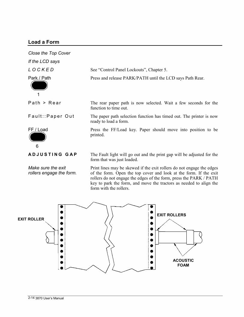
Make sure the exitrollers engage the form.
Print lines may be skewed if the exit rollers do not engage the edgesof the form. Open the top cover and look at the form. If the exitrollers do not engage the edges of the form, press the PARK / PATHkey to park the form, and move the tractors as needed to align theform with the rollers.
EXIT ROLLEREXIT ROLLERS
ACOUSTICFOAM
Set It Up and Get It Running 2-15
If paper did not load Check the paper path selection. Make sure that the paper is loaded inthe tractors that correspond to the paper path selection. If paper didnot load, take it out of the tractors and pull the jammed paper out ofthe printer from the tractor side and try again with a new sheet.
If paper is loaded, thefault light should be out.
If it is not, press the CLEAR key. When the printer is shipped, it isconfigured so that a paper-out fault is automatically cleared whenpaper is loaded. There is a software option that can be set so theCLEAR key must be pressed to clear the fault.
F o r m a t 4 The LCD shows which format is assigned to the current paper path.The format number can be 1, 2, 3, or 4. See Chapter 6 forinformation about formats.
Print a Test Pattern
The test pattern is called a rolling-ASCII pattern. The first 96 printable characters inthe ASCII chart are printed over and over again for as long as the test pattern isrunning. The test pattern is printed according to how the printer is currentlyconfigured in terms of margins, font, quality, characters per inch (cpi), lines per inch(lpi), etc. Some reasons for printing a test pattern are :
• to test the printer when starting it for the first time.
• to see how a different combination of font, cpi, or lpi settings looks on the currentpaper type.
CAUTION: Don’t print offthe paper !
Printing off the paper can damage the print head. Do not use the13.6” option unless using wide paper !
If the form is less thaneight inches wide ...
Use the LCD Menu to set a right margin less than or equal to theform width. See Chapter 3.
Format 4 The LCD should show a format number, which can be from 1 to 4.The default is format 4.
If a fault message isdisplayed ...
The LCD shows what the problem is. Clear the fault.
If some other messageis displayed...
The LCD menu may have been accessed. Press FIRST and thenENTER to exit the menu.
The On Line light shouldbe out.
If not, press the ON LINE key.
3870 User’s Manual2-16
Menu
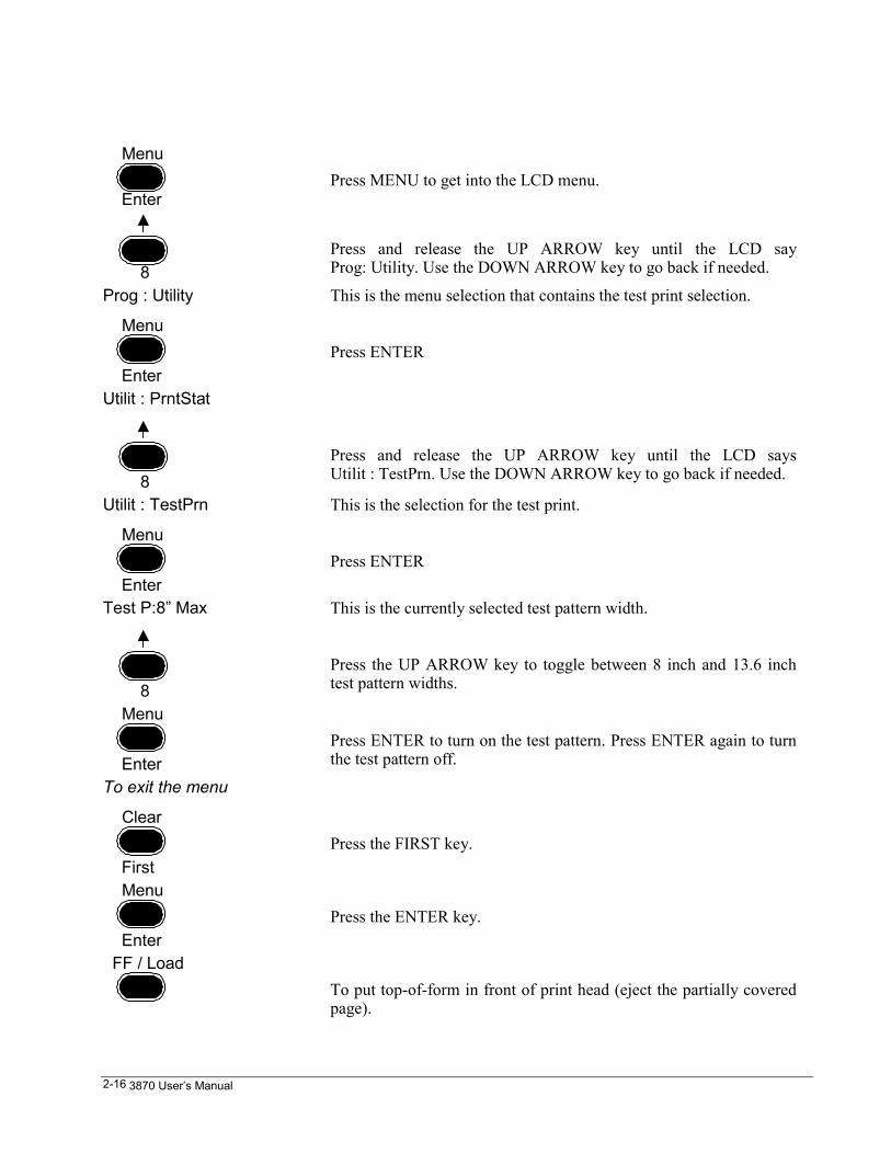
EnterPress MENU to get into the LCD menu.
8Press and release the UP ARROW key until the LCD sayProg: Utility. Use the DOWN ARROW key to go back if needed.
Prog : Utility This is the menu selection that contains the test print selection.
Menu
EnterPress ENTER
Utilit : PrntStat
8Press and release the UP ARROW key until the LCD saysUtilit : TestPrn. Use the DOWN ARROW key to go back if needed.
Utilit : TestPrn This is the selection for the test print.
Menu
EnterPress ENTER
Test P:8” Max This is the currently selected test pattern width.
8Press the UP ARROW key to toggle between 8 inch and 13.6 inchtest pattern widths.
Menu
EnterPress ENTER to turn on the test pattern. Press ENTER again to turnthe test pattern off.
To exit the menu
Clear
FirstPress the FIRST key.
Menu
EnterPress the ENTER key.
FF / LoadTo put top-of-form in front of print head (eject the partially coveredpage).
Set It Up and Get It Running 2-17
A Note About Print Head Gap Adjustment
Print head gap is the distance from the print head nozzle to the striker bar. If this gapis too tight, characters will smudge. If the gap is too large, characters will be light andragged, the printer will be noisy, and print head wear will accelerate.
As shipped, the printer is configured to automatically adjust the print head gapwhenever paper is loaded. The printer senses the thickness of a form when it is loadedand adjusts the print gap accordingly. The automatic gap adjustment process will leavea small black mark near the top of the first form as the form loads. Placing a sheet ofpaper in the gap at this time saves 1 form, but invalidates the gap.
The automatic print head adjustment can be fine tuned for best print quality.Semiautomatic head gap adjustment and fixed head gap may also be selected. Formore information on these selections see Chapter 7.
Adjust Top-of-Form
When loading the very first form, the printer feeds paper so that the top of the firstprintable line of characters is slightly below the top of the paper. Ideally, theapplication software that composes the page should advance paper to the first printline upon printing.
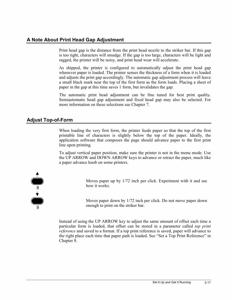
To adjust vertical paper position, make sure the printer is not in the menu mode. Usethe UP ARROW and DOWN ARROW keys to advance or retract the paper, much likea paper advance knob on some printers.
8Moves paper up by 1/72 inch per click. Experiment with it and seehow it works.
9Moves paper down by 1/72 inch per click. Do not move paper downenough to print on the striker bar.
Instead of using the UP ARROW key to adjust the same amount of offset each time aparticular form is loaded, that offset can be stored in a parameter called top printreference and saved to a format. If a top print reference is saved, paper will advance tothe right place each time that paper path is loaded. See “Set a Top Print Reference” inChapter 8.
3870 User’s Manual2-18
Attach to a Data Source
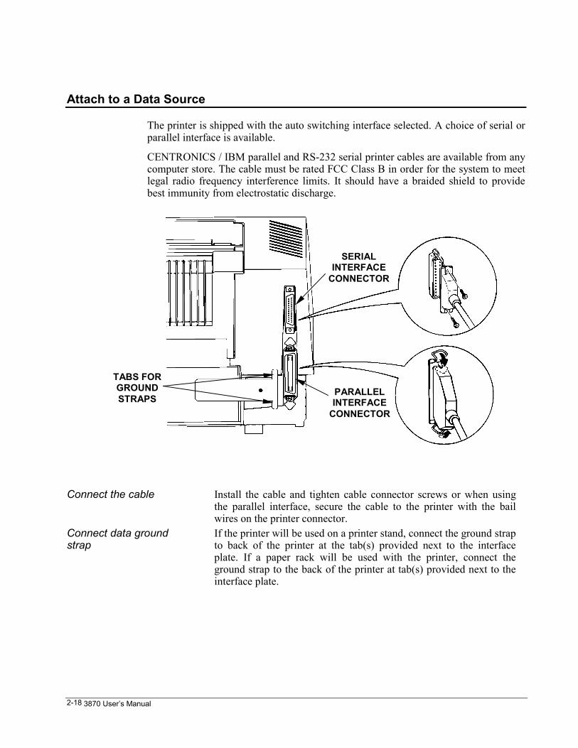
The printer is shipped with the auto switching interface selected. A choice of serial orparallel interface is available.
CENTRONICS / IBM parallel and RS-232 serial printer cables are available from anycomputer store. The cable must be rated FCC Class B in order for the system to meetlegal radio frequency interference limits. It should have a braided shield to providebest immunity from electrostatic discharge.
Connect the cable Install the cable and tighten cable connector screws or when usingthe parallel interface, secure the cable to the printer with the bailwires on the printer connector.
Connect data groundstrap
If the printer will be used on a printer stand, connect the ground strapto back of the printer at the tab(s) provided next to the interfaceplate. If a paper rack will be used with the printer, connect theground strap to the back of the printer at tab(s) provided next to theinterface plate.
TABS FORGROUNDSTRAPS
PARALLELINTERFACE
CONNECTOR
SERIALINTERFACE
CONNECTOR
Set It Up and Get It Running 2-19
When using the serialinterface
See Chapter 4 to set serial parameters.
When using the parallelinterface
See Chapter 4 to set parallel parameters.
Set the printer online The ON LINE light should be on. If it isn’t, then press the ON LINEkey to turn it on. The printer is shipped with the auto switchinginterface selected.
Print something from thedata source.
The printer will be able to print.
If it didn’t work ... Go to the next section and get a quick status to verify that the printeris set to the proper hardware interface. Note the emulation at thesame time. It’s easy to change either the interface selection or theemulation from the LCD menu.
Pinouts, signal descriptions, and other useful information about the interfaces iscovered in Chapter 12.
Quick Status
Check the current printer settings in terms of font, characters per inch, lines per inch,interface, and emulation by pressing the MENU / ENTER key while the printer isonline. The LCD steps through a list of the current settings for each of these fiveparameters.
LCD should say
F o r m a t 4 The format number will be from 1 to 4. If a fault message isdisplayed, clear the fault. If some other message is displayed, theprinter is probably somewhere in the LCD menu. Press FIRST, andthen ENTER, to get out.
The on light should beon.
If not, then press the ON LINE key.
Press MENU. The LCD will step through a short list of printersettings.
Menu
Enter

3870 User’s Manual2-20
Line Registration on the first form
Precise line registration depends on the form being fully engaged by the exit rollers.The printer is not guaranteed to hold specified line registration for the first inch of thefirst form. This also applies to cut sheets loaded from the manual paper path.
Control Panel 3-1
Chapter 3. Control PanelThe control panel keys do different things depending on whether the printer is online,offline, or in a menu. Any button function associated with the menu is shown on thepanel with blue lettering. This section assumes that the printer is set up as shipped,because it is possible to selectively lock out keys from the printed menu.
Control Panel Keys
If the LCD saysLOCKED
See “Control Panel Lockouts”, Chapter 5.
Park / Path
1
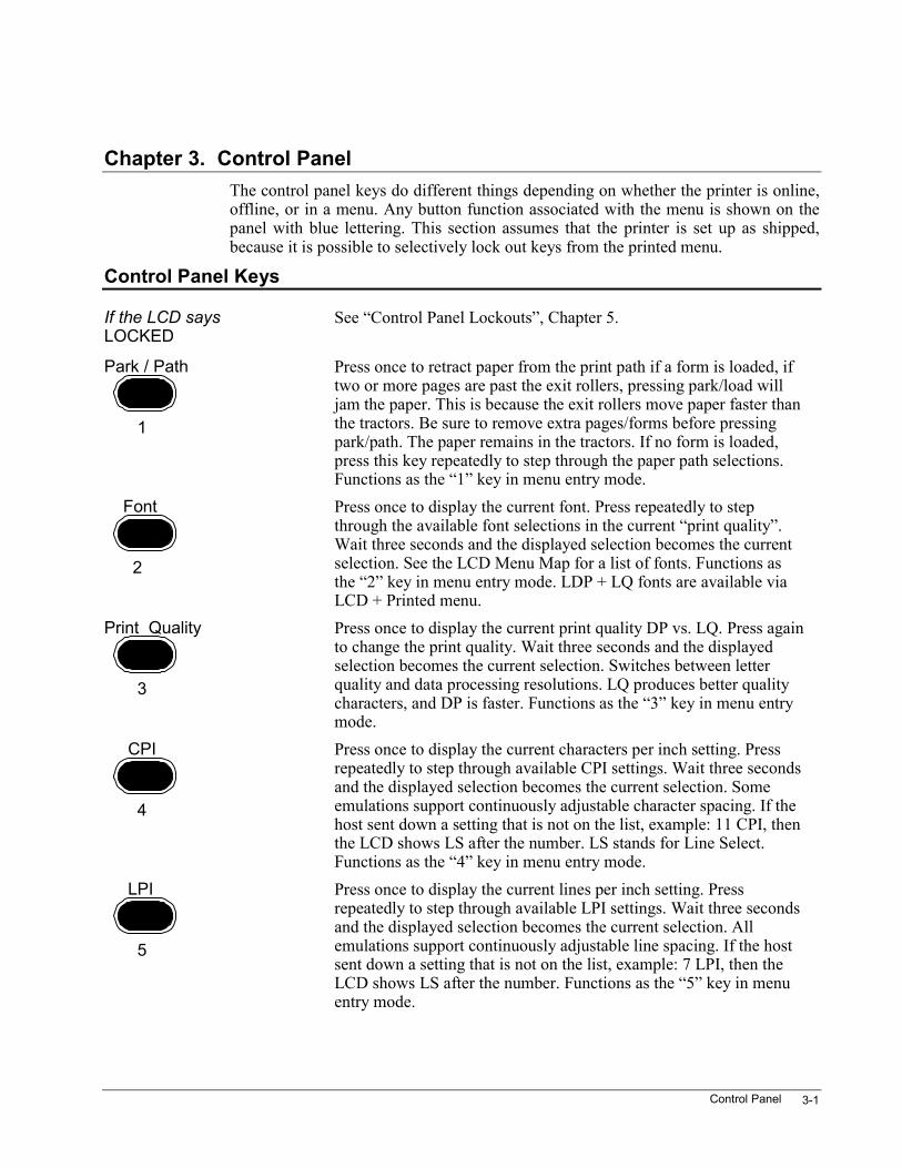
Press once to retract paper from the print path if a form is loaded, iftwo or more pages are past the exit rollers, pressing park/load willjam the paper. This is because the exit rollers move paper faster thanthe tractors. Be sure to remove extra pages/forms before pressingpark/path. The paper remains in the tractors. If no form is loaded,press this key repeatedly to step through the paper path selections.Functions as the “1” key in menu entry mode.
Font
2
Press once to display the current font. Press repeatedly to stepthrough the available font selections in the current “print quality”.Wait three seconds and the displayed selection becomes the currentselection. See the LCD Menu Map for a list of fonts. Functions asthe “2” key in menu entry mode. LDP + LQ fonts are available viaLCD + Printed menu.
Print Quality
3
Press once to display the current print quality DP vs. LQ. Press againto change the print quality. Wait three seconds and the displayedselection becomes the current selection. Switches between letterquality and data processing resolutions. LQ produces better qualitycharacters, and DP is faster. Functions as the “3” key in menu entrymode.
CPI
4
Press once to display the current characters per inch setting. Pressrepeatedly to step through available CPI settings. Wait three secondsand the displayed selection becomes the current selection. Someemulations support continuously adjustable character spacing. If thehost sent down a setting that is not on the list, example: 11 CPI, thenthe LCD shows LS after the number. LS stands for Line Select.Functions as the “4” key in menu entry mode.
LPI
5
Press once to display the current lines per inch setting. Pressrepeatedly to step through available LPI settings. Wait three secondsand the displayed selection becomes the current selection. Allemulations support continuously adjustable line spacing. If the hostsent down a setting that is not on the list, example: 7 LPI, then theLCD shows LS after the number. Functions as the “5” key in menuentry mode.
3870 User’s Manual3-2
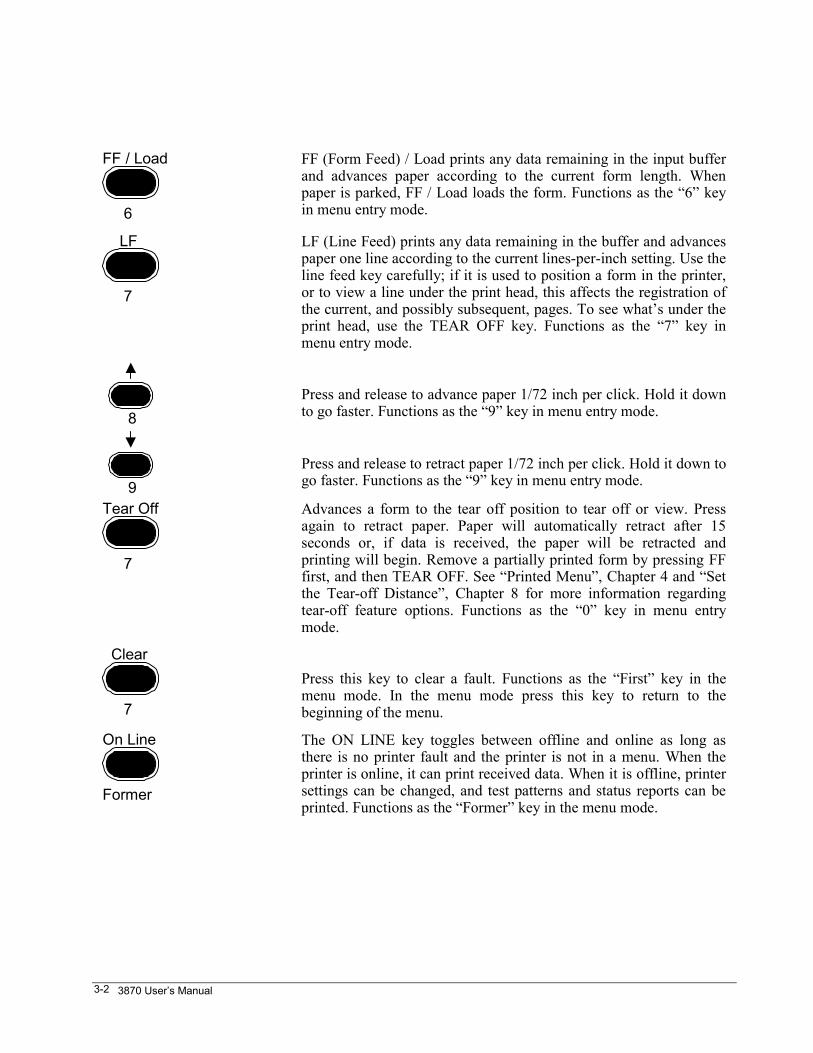
FF / Load
6
FF (Form Feed) / Load prints any data remaining in the input bufferand advances paper according to the current form length. Whenpaper is parked, FF / Load loads the form. Functions as the “6” keyin menu entry mode.
LF
7
LF (Line Feed) prints any data remaining in the buffer and advancespaper one line according to the current lines-per-inch setting. Use theline feed key carefully; if it is used to position a form in the printer,or to view a line under the print head, this affects the registration ofthe current, and possibly subsequent, pages. To see what’s under theprint head, use the TEAR OFF key. Functions as the “7” key inmenu entry mode.
8Press and release to advance paper 1/72 inch per click. Hold it downto go faster. Functions as the “9” key in menu entry mode.
9Press and release to retract paper 1/72 inch per click. Hold it down togo faster. Functions as the “9” key in menu entry mode.
Tear Off
7
Advances a form to the tear off position to tear off or view. Pressagain to retract paper. Paper will automatically retract after 15seconds or, if data is received, the paper will be retracted andprinting will begin. Remove a partially printed form by pressing FFfirst, and then TEAR OFF. See “Printed Menu”, Chapter 4 and “Setthe Tear-off Distance”, Chapter 8 for more information regardingtear-off feature options. Functions as the “0” key in menu entrymode.
Clear
7
Press this key to clear a fault. Functions as the “First” key in themenu mode. In the menu mode press this key to return to thebeginning of the menu.
On Line
Former
The ON LINE key toggles between offline and online as long asthere is no printer fault and the printer is not in a menu. When theprinter is online, it can print received data. When it is offline, printersettings can be changed, and test patterns and status reports can beprinted. Functions as the “Former” key in the menu mode.
Control Panel 3-3
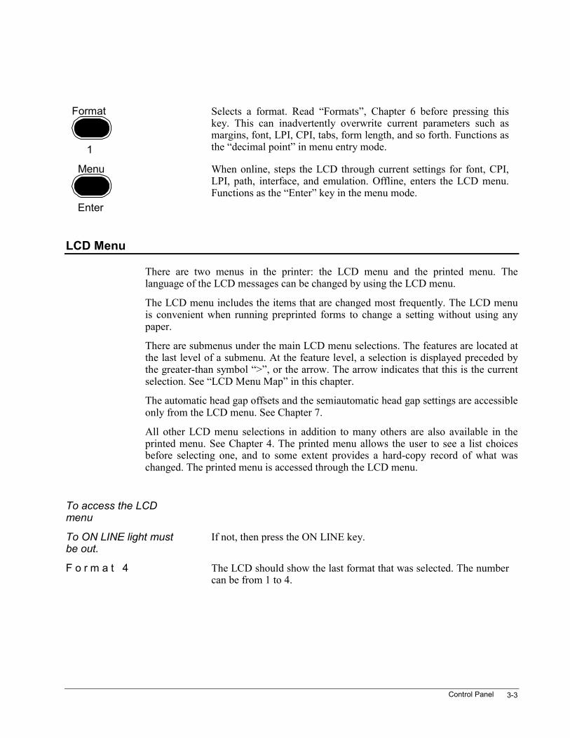
Format
1
Selects a format. Read “Formats”, Chapter 6 before pressing thiskey. This can inadvertently overwrite current parameters such asmargins, font, LPI, CPI, tabs, form length, and so forth. Functions asthe “decimal point” in menu entry mode.
Menu
Enter
When online, steps the LCD through current settings for font, CPI,LPI, path, interface, and emulation. Offline, enters the LCD menu.Functions as the “Enter” key in the menu mode.
LCD Menu
There are two menus in the printer: the LCD menu and the printed menu. Thelanguage of the LCD messages can be changed by using the LCD menu.
The LCD menu includes the items that are changed most frequently. The LCD menuis convenient when running preprinted forms to change a setting without using anypaper.
There are submenus under the main LCD menu selections. The features are located atthe last level of a submenu. At the feature level, a selection is displayed preceded bythe greater-than symbol “>”, or the arrow. The arrow indicates that this is the currentselection. See “LCD Menu Map” in this chapter.
The automatic head gap offsets and the semiautomatic head gap settings are accessibleonly from the LCD menu. See Chapter 7.
All other LCD menu selections in addition to many others are also available in theprinted menu. See Chapter 4. The printed menu allows the user to see a list choicesbefore selecting one, and to some extent provides a hard-copy record of what waschanged. The printed menu is accessed through the LCD menu.
To access the LCDmenu
To ON LINE light mustbe out.
If not, then press the ON LINE key.
F o r m a t 4 The LCD should show the last format that was selected. The numbercan be from 1 to 4.
3870 User’s Manual3-4
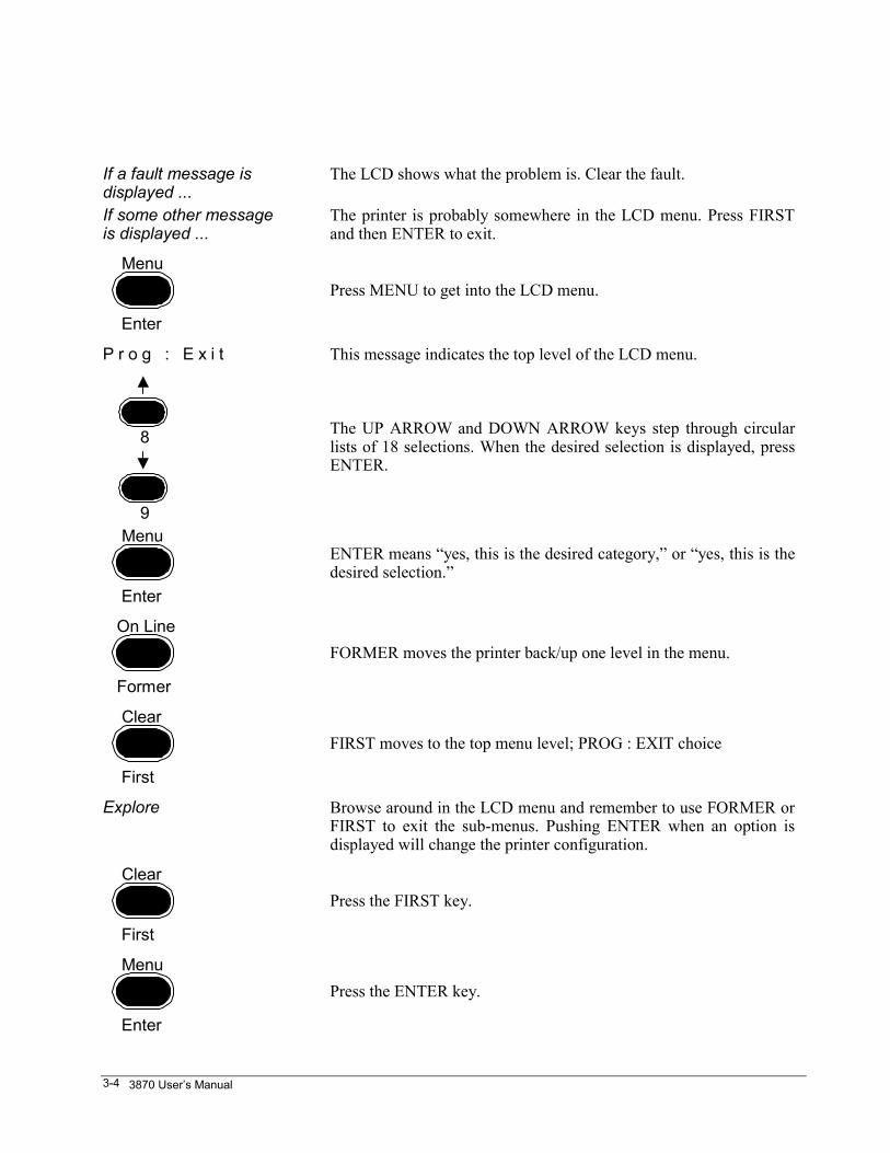
If a fault message isdisplayed ...
The LCD shows what the problem is. Clear the fault.
If some other messageis displayed ...
The printer is probably somewhere in the LCD menu. Press FIRSTand then ENTER to exit.
Menu
Enter
Press MENU to get into the LCD menu.
P r o g : E x i t This message indicates the top level of the LCD menu.
8
9
The UP ARROW and DOWN ARROW keys step through circularlists of 18 selections. When the desired selection is displayed, pressENTER.
Menu
Enter
ENTER means “yes, this is the desired category,” or “yes, this is thedesired selection.”
On Line
Former
FORMER moves the printer back/up one level in the menu.
Clear
First
FIRST moves to the top menu level; PROG : EXIT choice
Explore Browse around in the LCD menu and remember to use FORMER orFIRST to exit the sub-menus. Pushing ENTER when an option isdisplayed will change the printer configuration.
Clear
First
Press the FIRST key.
Menu
Enter
Press the ENTER key.
Control Panel 3-5
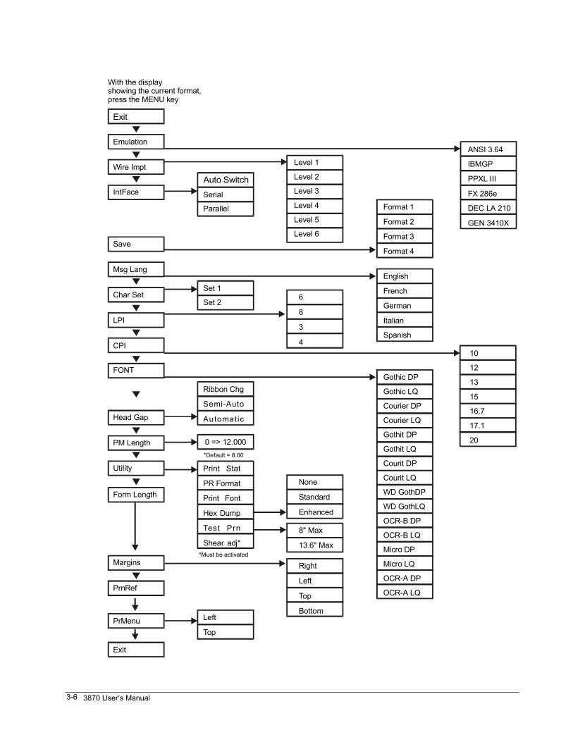
LCD Menu Map
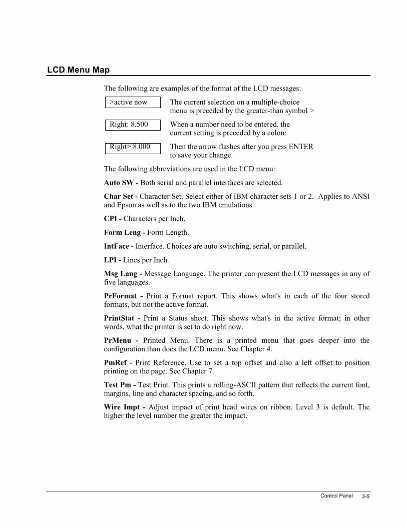
The following are examples of the format of the LCD messages:
>active now The current selection on a multiple-choicemenu is preceded by the greater-than symbol >
Right: 8.500 When a number need to be entered, thecurrent setting is preceded by a colon:
Right> 8.000 Then the arrow flashes after you press ENTERto save your change.
The following abbreviations are used in the LCD menu:
Auto SW - Both serial and parallel interfaces are selected.
Char Set - Character Set. Select either of IBM character sets 1 or 2. Applies to ANSIand Epson as well as to the two IBM emulations.
CPI - Characters per Inch.
Form Leng - Form Length.
IntFace - Interface. Choices are auto switching, serial, or parallel.
LPI - Lines per Inch.
Msg Lang - Message Language. The printer can present the LCD messages in any offive languages.
PrFormat - Print a Format report. This shows what's in each of the four storedformats, but not the active format.
PrintStat - Print a Status sheet. This shows what's in the active format; in otherwords, what the printer is set to do right now.
PrMenu - Printed Menu. There is a printed menu that goes deeper into theconfiguration than does the LCD menu. See Chapter 4.
PmRef - Print Reference. Use to set a top offset and also a left offset to positionprinting on the page. See Chapter 7.
Test Pm - Test Print. This prints a rolling-ASCII pattern that reflects the current font,margins, line and character spacing, and so forth.
Wire Impt - Adjust impact of print head wires on ribbon. Level 3 is default. Thehigher the level number the greater the impact.
3870 User’s Manual3-6
Auto Switch
Exit
Serial
Level 1ANSI 3.64
IBMGP
PPXL III
FX 286e
DEC LA 210
GEN 3410X
10
12
13
15
16.7
17.1
20
6
8
3
4
None
Standard
Enhanced
Right
Left
Top
Bottom
8" Max
13.6" Max
Level 2
Level 3
Level 4
Level 5Format 1
English
Gothic DP
Gothic LQ
Courier DP
Courier LQ
Gothit DP
Gothit LQ
Courit DP
Courit LQ
WD GothDP
WD GothLQ
OCR-B DP
OCR-B LQ
Micro DP
Micro LQ
OCR-A DP
OCR-A LQ
Format 2
French
Format 3
German
Format 4
Italian
Spanish
Level 6
Set 1
Left
Top
Ribbon Chg
Semi-Auto
Automatic
Print Stat
PR Format
Print Font
Hex Dump
Test Prn
Shear adj*
0 => 12.000*Default = 8.00
*Must be activated
Emulation
Wire Impt
IntFace
Save
Msg Lang
Char Set
LPI
CPI
FONT
Head Gap
PM Length
Utility
Form Length
Margins
PrnRef
PrMenu
Exit
Parallel
Set 2
With the displayshowing the current format,press the MENU key
Control Panel 3-7
Select the Emulation
When the printer is shipped, the emulation is set to ANSI (American NationalStandards Institute). This printer-control protocol is the native language of the printer.The printer's bar code / rotatable oversized character features are accessible via ANSIcontrol sequences.
ANSI is not widely supported by off-the-shelf office applications. If the printer isattached to a personal computer, and the printer is used for general-purpose officework, the emulation may be changed to Epson FX286e, Dec LA210, CENICOM341OX, IBM Proprinter XL III, or IBM-CP.
This section explains how to change emulations from the control panel. Emulationscan also be changed from the printed menu or by sending escape sequences from thehost. See the ANSI chapter in the Programmer's Manual for details.
Whatever method is used to set the emulation, the printer will power up in thatemulation until the setting is changed.
Note: Emulation selections cannot be saved to the individual user-defined formats1-4. The emulation selection applies to all formats. When an emulation is chosen, thatselection applies to the active format and does not change when any of the four user-defined formats are made active.
The emulation selection is saved in nonvolatile RAM; when the printer is turned on, itwill be in the same emulation it was in when it was turned off.
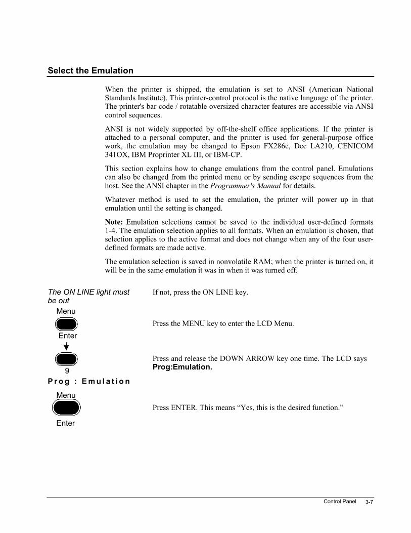
The ON LINE light mustbe out
If not, press the ON LINE key.
Menu
EnterPress the MENU key to enter the LCD Menu.
9Press and release the DOWN ARROW key one time. The LCD saysProg:Emulation.
P r o g : E m u l a t i o n
Menu
Enter
Press ENTER. This means “Yes, this is the desired function.”
3870 User’s Manual3-8
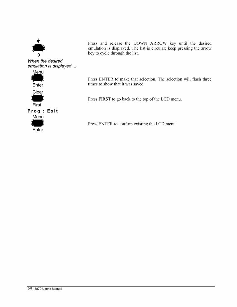
9
Press and release the DOWN ARROW key until the desiredemulation is displayed. The list is circular; keep pressing the arrowkey to cycle through the list.
When the desiredemulation is displayed ... Menu
EnterPress ENTER to make that selection. The selection will flash threetimes to show that it was saved.
Clear
FirstPress FIRST to go back to the top of the LCD menu.
P r o g : E x i t Menu
EnterPress ENTER to confirm existing the LCD menu.
Control Panel 3-9
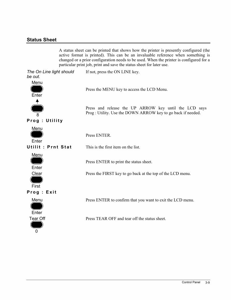
Status Sheet
A status sheet can be printed that shows how the printer is presently configured (theactive format is printed). This can be an invaluable reference when something ischanged or a prior configuration needs to be used. When the printer is configured for aparticular print job, print and save the status sheet for later use.
The On Line light shouldbe out.
If not, press the ON LINE key.
Menu
EnterPress the MENU key to access the LCD Menu.
8Press and release the UP ARROW key until the LCD saysProg : Utility. Use the DOWN ARROW key to go back if needed.
P r o g : U t i l i t y
Menu
EnterPress ENTER.
U t i l i t : P r n t S t a t This is the first item on the list.
Menu
EnterPress ENTER to print the status sheet.
Clear
First
Press the FIRST key to go back at the top of the LCD menu.
P r o g : E x i t
Menu
Enter
Press ENTER to confirm that you want to exit the LCD menu.
Tear Off
0
Press TEAR OFF and tear off the status sheet.
Printed Menu 4-1
Chapter 4. Printed MenuExperiment with the printed menu to see how it works. To keep the printer asoriginally configured, select Abort instead of Save when exiting the printed menu.
This menu is printed in English only.
The menus are printed at 10 CPI, 6 LPI, in the ANSI default font. This is normallyGothic DP, but this can be changed by using the SGR Extension command describedin the ANSI chapter of the Programmer’s Manuals. The only other setting that affectsthe way the menus look are the margins in the active format.
The > Arrow Means the Option Is Enabled
At the last level of a menu branch, some options on the list may be preceded by thegreater-than symbol (or arrow). The arrow points to options that are currently enabled.
In some submenus, the arrow points to one of a mutually exclusive set of options. Forinstance, only one font may be selected.
In other submenus, the options aren’t mutually exclusive. In the Printing Modesubmenu, for example, Unidirectional Graphics and Unidirectional DP may beselected at the same time.
When options aren’t mutually exclusive, entering an option number toggles thatoption. If Unidirectional Graphics is currently off and the number for that option isentered, it will be turned on, and vice versa.
3870 User’s Manual4-2
Sometimes Values Are Entered
Instead of offering multiple choices, the printer requires actual values for featuressuch as line spacing and margins. Use the numbers and decimal point on the bottom ofthe keys to make numeric entries. The context of a particular menu indicates the unitsof measure required, such as columns, inches, etc.
Decimal fractions may be included, in which case the printer might round off the entryto the nearest number that the current emulation supports.
The printer can be set to accept decipoints for margins and form length where it wouldnormally expect inches; this is controlled by software options 9 and 10 on the printedmenu. See "Software Options" in this chapter.
Access the Printed Menu
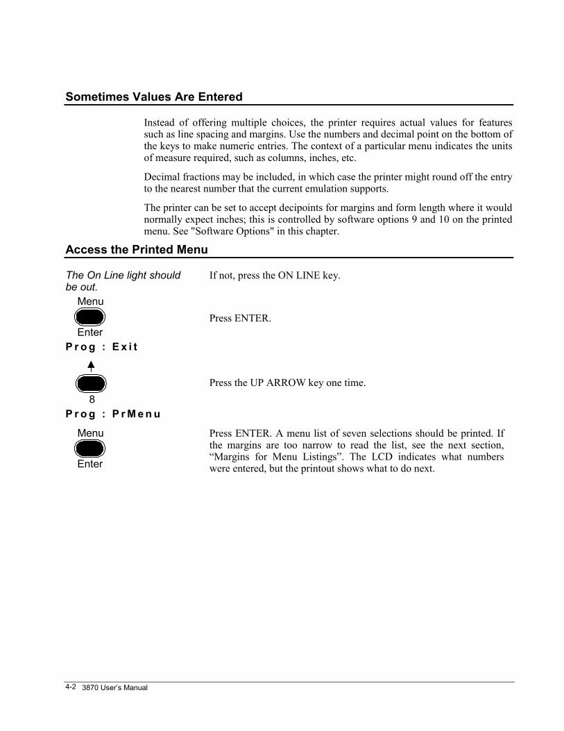
The On Line light shouldbe out.
If not, press the ON LINE key.
Menu
EnterPress ENTER.
P r o g : E x i t
8Press the UP ARROW key one time.
P r o g : P r M e n u
Menu
Enter
Press ENTER. A menu list of seven selections should be printed. Ifthe margins are too narrow to read the list, see the next section,“Margins for Menu Listings”. The LCD indicates what numberswere entered, but the printout shows what to do next.
Printed Menu 4-3
Margins for Menu Listings
In the printed menu, the lists of options are designed to be printed with a left marginof 0 inches and a right margin of at least 8.0 inches. If the margins selected are greaterthan the left margin of 0 inches and less than the right margin of 8.0 inches, thenchange the margins prior to using the printed menu.
If the margins are too narrow, then exit the printed menu. Press FIRST and then 1.1and Enter to abort. Enter the LCD Menu by pressing FIRST and then ENTER. Notethe format number shown on the LCD. This is the currently assigned format. Use theFORMAT key to select a different format while printing the menu. Use the FORMATkey to select the old format when the menu printing is finished.
FORMER and FIRST
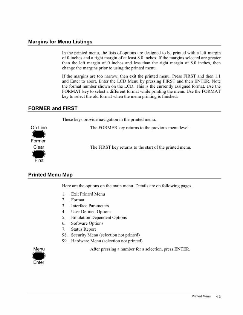
These keys provide navigation in the printed menu.
On Line
Former
The FORMER key returns to the previous menu level.
Clear
First
The FIRST key returns to the start of the printed menu.
Printed Menu Map
Here are the options on the main menu. Details are on following pages.
1. Exit Printed Menu2. Format3. Interface Parameters4. User Defined Options5. Emulation Dependent Options6. Software Options7. Status Report98. Security Menu (selection not printed)99. Hardware Menu (selection not printed)
Menu
Enter
After pressing a number for a selection, press ENTER.
3870 User’s Manual4-4
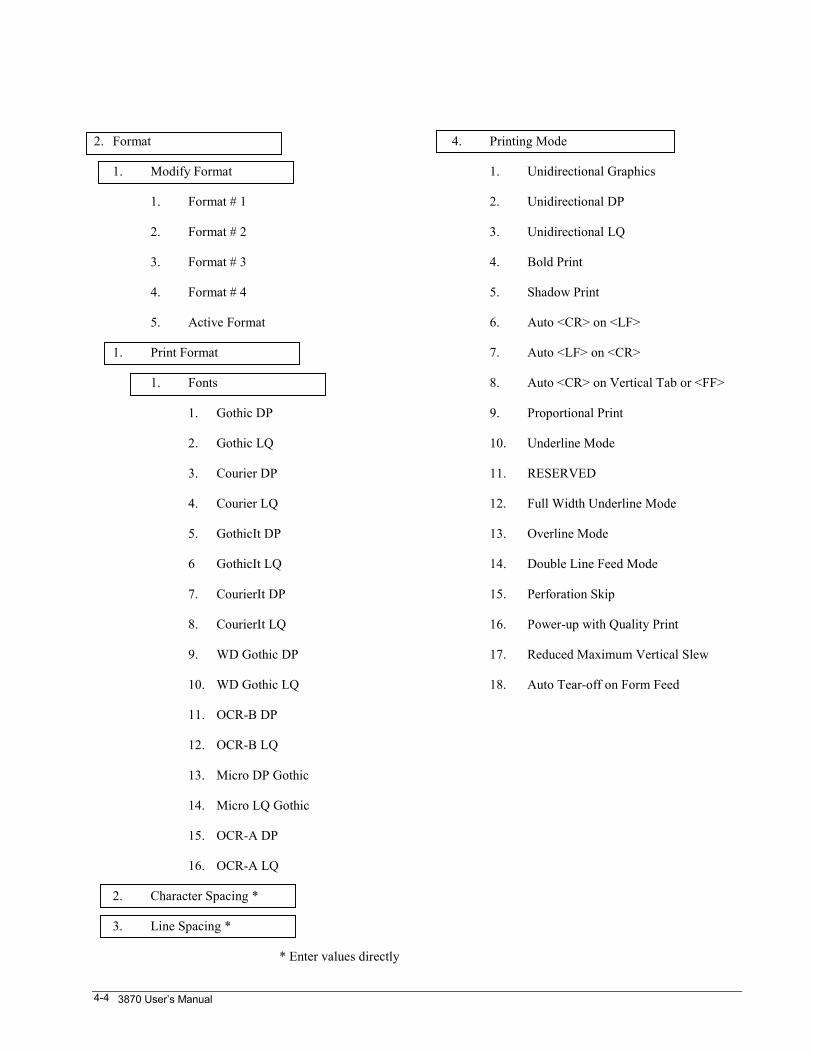
2. Format
1. Modify Format
1. Format # 1
2. Format # 2
3. Format # 3
4. Format # 4
5. Active Format
1. Print Format
1. Fonts
1. Gothic DP
2. Gothic LQ
3. Courier DP
4. Courier LQ
5. GothicIt DP
6 GothicIt LQ
7. CourierIt DP
8. CourierIt LQ
9. WD Gothic DP
10. WD Gothic LQ
11. OCR-B DP
12. OCR-B LQ
13. Micro DP Gothic
14. Micro LQ Gothic
15. OCR-A DP
16. OCR-A LQ
2. Character Spacing *
3. Line Spacing *
* Enter values directly
4. Printing Mode
1. Unidirectional Graphics
2. Unidirectional DP
3. Unidirectional LQ
4. Bold Print
5. Shadow Print
6. Auto <CR> on <LF>
7. Auto <LF> on <CR>
8. Auto <CR> on Vertical Tab or <FF>
9. Proportional Print
10. Underline Mode
11. RESERVED
12. Full Width Underline Mode
13. Overline Mode
14. Double Line Feed Mode
15. Perforation Skip
16. Power-up with Quality Print
17. Reduced Maximum Vertical Slew
18. Auto Tear-off on Form Feed

Printed Menu 4-5
5. National Character Substitutions
0. US ASCII
1. German
2. French A
3. French B
4. French Canadian
5. Dutch (Netherlands)
6. Italian
7. U.K.
8. Spanish
9. Danish/Norwegian A
10. Danish/Norwegian B
11. Danish/Norwegian C
12. Danish/Norwegian D
13. Swedish/Finnish A
14. Swedish/Finnish A
15. Swedish/Finnish C
16. Swedish/Finnish D
17. Swiss
18. Danish/Norwegian E
19. ISO 8859-1 Latin 1
20. ISO 8859-2 Latin 2
21. ISO 8859-3 Latin 3
22. ISO 8859-4 Latin 4
23. MS Code Page 437 ENGLISH
24. MS Code Page 850 MULTI 2
25. MS Code Page 852 SLAVIC
26. MS Code Page 863 Canadian/French
27. ROMAN 8 Hp
28. Mazowia
29. ISO 8859-9 Latin 5
30. Turkish
31. Greek
32. Kamenicky
33. FX 286e France
34. FX 286e Germany
35. FX 286e UK
36. FX 286e Denmark I
37. FX 286e Sweden
38. FX 286e Italy
39. FX 286e Spain I
40. FX 286e Japan
41. FX 286e Norway
42. FX 286e Denmark II
43. FX 286e Spain II
44. FX 286e Latin America
45. MS Code Page 864 IBM PC Arabic
3870 User’s Manual4-6
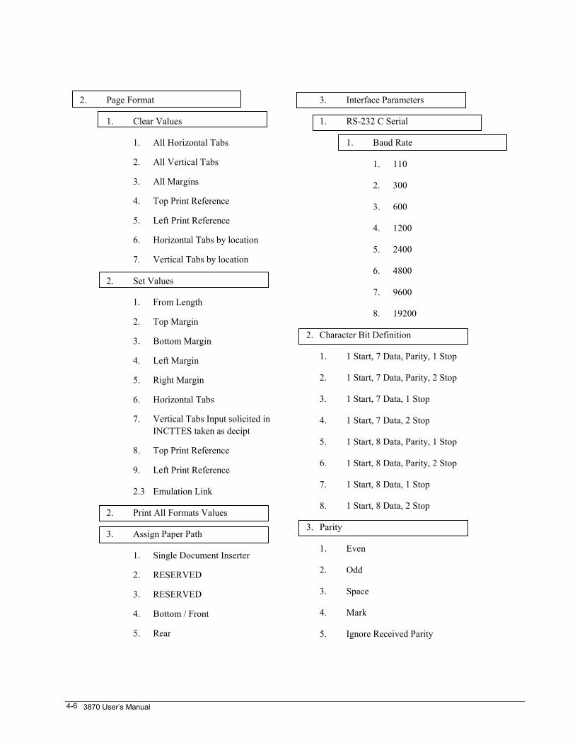
2. Page Format
1. Clear Values
1. All Horizontal Tabs
2. All Vertical Tabs
3. All Margins
4. Top Print Reference
5. Left Print Reference
6. Horizontal Tabs by location
7. Vertical Tabs by location
2. Set Values
1. From Length
2. Top Margin
3. Bottom Margin
4. Left Margin
5. Right Margin
6. Horizontal Tabs
7. Vertical Tabs Input solicited inINCTTES taken as decipt
8. Top Print Reference
9. Left Print Reference
2.3 Emulation Link
2. Print All Formats Values
3. Assign Paper Path
1. Single Document Inserter
2. RESERVED
3. RESERVED
4. Bottom / Front
5. Rear
3. Interface Parameters
1. RS-232 C Serial
1. Baud Rate
1. 110
2. 300
3. 600
4. 1200
5. 2400
6. 4800
7. 9600
8. 19200
2. Character Bit Definition
1. 1 Start, 7 Data, Parity, 1 Stop
2. 1 Start, 7 Data, Parity, 2 Stop
3. 1 Start, 7 Data, 1 Stop
4. 1 Start, 7 Data, 2 Stop
5. 1 Start, 8 Data, Parity, 1 Stop
6. 1 Start, 8 Data, Parity, 2 Stop
7. 1 Start, 8 Data, 1 Stop
8. 1 Start, 8 Data, 2 Stop
3. Parity
1. Even
2. Odd
3. Space
4. Mark
5. Ignore Received Parity
Printed Menu 4-7
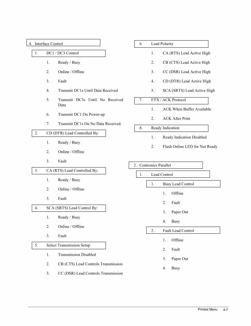
4. Interface Control
1. DC1 / DC3 Control
1. Ready / Busy
2. Online / Offline
3. Fault
4. Transmit DC1s Until Data Received
5. Transmit DC3s Until No ReceivedData
6. Transmit DC1 On Power-up
7. Transmit DC1s On No Data Received.
2. CD (DTR) Lead Controlled By:
1. Ready / Busy
2. Online / Offline
3. Fault
3. CA (RTS) Lead Controlled By:
1. Ready / Busy
2. Online / Offline
3. Fault
4. SCA (SRTS) Lead Control By:
1. Ready / Busy
2. Online / Offline
3. Fault
5. Select Transmission Setup
1. Transmission Disabled
2. CB (CTS) Lead Controls Transmission
3. CC (DSR) Lead Controls Transmission
6. Lead Polarity
1. CA (RTS) Lead Active High
2. CB (CTS) Lead Active High
3. CC (DSR) Lead Active High
4. CD (DTR) Lead Active High
5. SCA (SRTS) Lead Active High
7. ETX / ACK Protocol
1. ACK When Buffer Available
2. ACK After Print
8. Ready Indication
1. Ready Indication Disabled
2. Flash Online LED for Not Ready
2. Centronics Parallel
1. Lead Control
1. Busy Lead Control
1. Offline
2. Fault
3. Paper Out
4. Busy
2. Fault Lead Control
1. Offline
2. Fault
3. Paper Out
4. Busy
3870 User’s Manual4-8
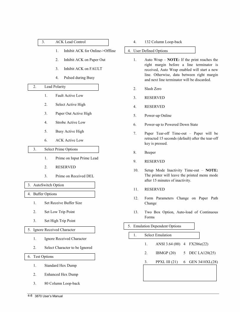
3. ACK Lead Control
1. Inhibit ACK for Online->Offline
2. Inhibit ACK on Paper Out
3. Inhibit ACK on FAULT
4. Pulsed during Busy
2. Lead Polarity
1. Fault Active Low
2. Select Active High
3. Paper Out Active High
4. Strobe Active Low
5. Busy Active High
6. ACK Active Low
3. Select Prime Options
1. Prime on Input Prime Lead
2. RESERVED
3. Prime on Received DEL
3. AutoSwitch Option
4. Buffer Options
1. Set Receive Buffer Size
2. Set Low Trip Point
3. Set High Trip Point
5. Ignore Received Character
1. Ignore Received Character
2. Select Character to be Ignored
6. Test Options
1. Standard Hex Dump
2. Enhanced Hex Dump
3. 80 Column Loop-back
4. 132 Column Loop-back
4. User Defined Options
1. Auto Wrap – NOTE: If the print reaches theright margin before a line terminator isreceived, Auto Wrap enabled will start a newline. Otherwise, data between right marginand next line terminator will be discarded.
2. Slash Zero
3. RESERVED
4. RESERVED
5. Power-up Online
6. Power-up to Powered Down State
7. Paper Tear-off Time-out – Paper will beretracted 15 seconds (default) after the tear-offkey is pressed.
8. Beeper
9. RESERVED
10. Setup Mode Inactivity Time-out – NOTE:The printer will leave the printed menu modeafter 15 minutes of inactivity.
11. RESERVED
12. Form Parameters Change on Paper PathChange
13. Two Box Option, Auto-load of ContinuousForms
5. Emulation Dependent Options
1. Select Emulation
1. ANSI 3.64 (00) 4 FX286e(22)
2. IBMGP (20) 5 DEC LA120(25)
3. PPXL III (21) 6 GEN 3410XL(28)
Printed Menu 4-9
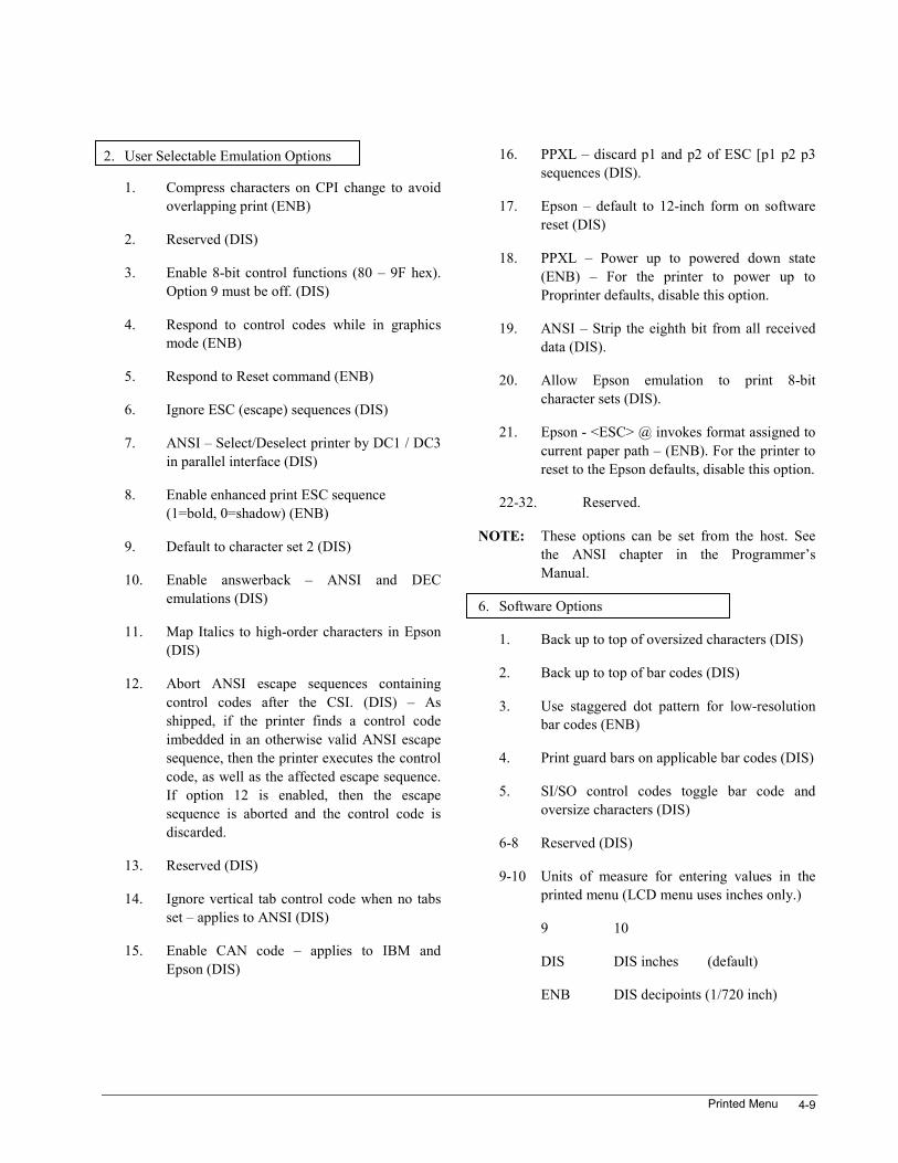
2. User Selectable Emulation Options
1. Compress characters on CPI change to avoidoverlapping print (ENB)
2. Reserved (DIS)
3. Enable 8-bit control functions (80 – 9F hex).Option 9 must be off. (DIS)
4. Respond to control codes while in graphicsmode (ENB)
5. Respond to Reset command (ENB)
6. Ignore ESC (escape) sequences (DIS)
7. ANSI – Select/Deselect printer by DC1 / DC3in parallel interface (DIS)
8. Enable enhanced print ESC sequence(1=bold, 0=shadow) (ENB)
9. Default to character set 2 (DIS)
10. Enable answerback – ANSI and DECemulations (DIS)
11. Map Italics to high-order characters in Epson(DIS)
12. Abort ANSI escape sequences containingcontrol codes after the CSI. (DIS) – Asshipped, if the printer finds a control codeimbedded in an otherwise valid ANSI escapesequence, then the printer executes the controlcode, as well as the affected escape sequence.If option 12 is enabled, then the escapesequence is aborted and the control code isdiscarded.
13. Reserved (DIS)
14. Ignore vertical tab control code when no tabsset – applies to ANSI (DIS)
15. Enable CAN code – applies to IBM andEpson (DIS)
16. PPXL – discard p1 and p2 of ESC [p1 p2 p3sequences (DIS).
17. Epson – default to 12-inch form on softwarereset (DIS)
18. PPXL – Power up to powered down state(ENB) – For the printer to power up toProprinter defaults, disable this option.
19. ANSI – Strip the eighth bit from all receiveddata (DIS).
20. Allow Epson emulation to print 8-bitcharacter sets (DIS).
21. Epson - <ESC> @ invokes format assigned tocurrent paper path – (ENB). For the printer toreset to the Epson defaults, disable this option.
22-32. Reserved.
NOTE: These options can be set from the host. Seethe ANSI chapter in the Programmer’sManual.
6. Software Options
1. Back up to top of oversized characters (DIS)
2. Back up to top of bar codes (DIS)
3. Use staggered dot pattern for low-resolutionbar codes (ENB)
4. Print guard bars on applicable bar codes (DIS)
5. SI/SO control codes toggle bar code andoversize characters (DIS)
6-8 Reserved (DIS)
9-10 Units of measure for entering values in theprinted menu (LCD menu uses inches only.)
9 10
DIS DIS inches (default)
ENB DIS decipoints (1/720 inch)
3870 User’s Manual4-10
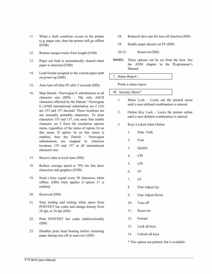
11. When a fault condition occurs in the printer(e.g. paper out), then the printer will go offline(ENB).
12. Bottom margin tracks form length (ENB)
13. Paper out fault is automatically cleared whenpaper is detected (ENB)
14. Load format assigned to the current paper pathon power-up (DIS)
15. Auto tear-off after FF after 5 seconds (DIS)
16. Map Danish / Norwegian E substitutions to allcharacter sets (DIS) – The only ASCIIcharacters affected by the Danish / NorwegianE (ANSI international substitution set # (18)are 155 and 157 decimal. These locations arenot normally printable characters. To printcharacters 155 and 157, you must first enablecharacter set 2 from the emulation optionsmenu, regardless of the status of option 16 onthis menu. If option 16 on this menu isenabled, then the Danish / Norwegiansubstitutions are mapped to characterlocations 155 and 157 in all internationalcharacter sets.
17. Receive data in local state (DIS)
18. Reduce carriage speed to 70% for line drawcharacters and graphics (ENB)
19. Send a busy signal every 20 characters whenoffline. (DIS) Only applies if option 17 isenabled
20. Reserved (DIS)
21. Strip leading and trailing white space fromPOSTNET bar codes and change density from20 dpi, to 24 dpi (DIS)
22. Print POSTNET bar codes unidirectionally(DIS)
23. Disables print head homing before retractingpaper during tear-off or autoview (DIS)
24. Reduced slew rate for tear-off function (DIS)
25. Enable paper shearer on FF (DIS)
26-32. Reserved (DIS)
NOTE: These options can be set from the host. Seethe ANSI chapter in the Programmer’sManual.
7. Status Report –
Prints a status report
98. Security Menu*
1. Menu Lock – Locks out the printed menuuntil a user-defined combination is entered.
2. Online Key Lock – Locks the printer onlineuntil a user-defined combination is entered.
3. Keys Locked when Online
1. Park / Path
2. Font
3. Quality
4. CPI
5. LPI
6. FF
7. LF
8. Fine Adjust Up
9. Fine Adjust Down
10. Tear-off
11. Reserved
12. Format
13. Lock all keys
14. Unlock all keys
* This option not printed, but is available
Printed Menu 4-11
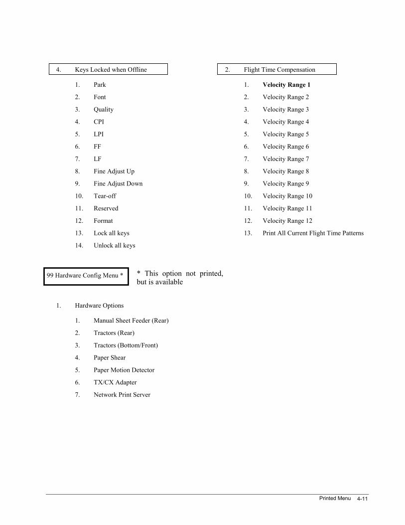
4. Keys Locked when Offline
1. Park
2. Font
3. Quality
4. CPI
5. LPI
6. FF
7. LF
8. Fine Adjust Up
9. Fine Adjust Down
10. Tear-off
11. Reserved
12. Format
13. Lock all keys
14. Unlock all keys
99 Hardware Config Menu *
1. Hardware Options
1. Manual Sheet Feeder (Rear)
2. Tractors (Rear)
3. Tractors (Bottom/Front)
4. Paper Shear
5. Paper Motion Detector
6. TX/CX Adapter
7. Network Print Server
2. Flight Time Compensation
1. Velocity Range 1
2. Velocity Range 2
3. Velocity Range 3
4. Velocity Range 4
5. Velocity Range 5
6. Velocity Range 6
7. Velocity Range 7
8. Velocity Range 8
9. Velocity Range 9
10. Velocity Range 10
11. Velocity Range 11
12. Velocity Range 12
13. Print All Current Flight Time Patterns
* This option not printed,but is available
3870 User’s Manual4-12
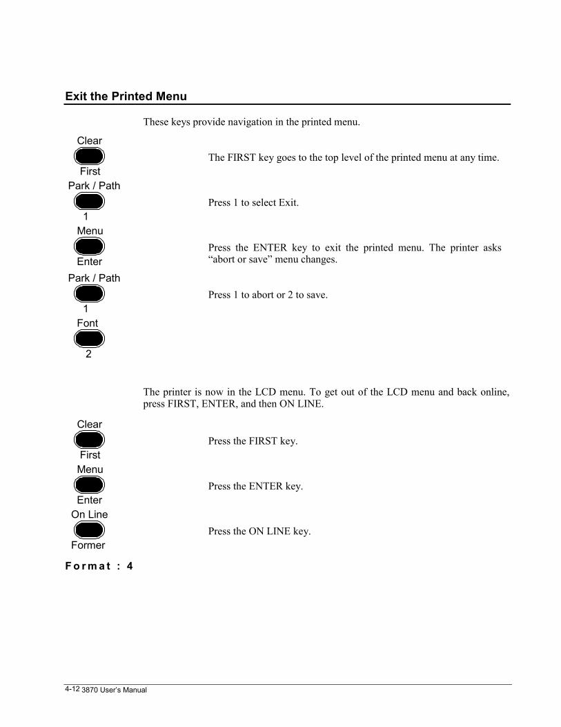
Exit the Printed Menu
These keys provide navigation in the printed menu.
Clear
FirstThe FIRST key goes to the top level of the printed menu at any time.
Park / Path
1Press 1 to select Exit.
Menu
EnterPress the ENTER key to exit the printed menu. The printer asks“abort or save” menu changes.
Park / Path
1Press 1 to abort or 2 to save.
Font
2
The printer is now in the LCD menu. To get out of the LCD menu and back online,press FIRST, ENTER, and then ON LINE.
Clear
FirstPress the FIRST key.
Menu
EnterPress the ENTER key.
On Line
FormerPress the ON LINE key.
F o r m a t : 4
Control Panel Lockouts 5-1
Chapter 5. Control Panel LockoutsWhen LOCKED is displayed on the LCD, it is usually because the printer is onlineand the user is pressing one of the keys that are supposed to work offline only, likeFONT or CPI. If LOCKED is displayed and the ON LINE light is on, press the ONLINE key to turn it off.
If a user tries to go offline and gets flashing lights and a prompt to enter a code, theprinter has been locked online, either get the combination or resort to one of theremedies described later in this chapter to recover. The printed menu can also belocked out in a similar way.
If LOCKED is unexpectedly displayed, a user may have locked out some of the keys.This printer allows considerable control over which control panel keys work onlineand which keys will not.
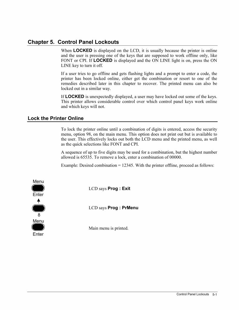
Lock the Printer Online
To lock the printer online until a combination of digits is entered, access the securitymenu, option 98, on the main menu. This option does not print out but is available tothe user. This effectively locks out both the LCD menu and the printed menu, as wellas the quick selections like FONT and CPI.
A sequence of up to five digits may be used for a combination, but the highest numberallowed is 65535. To remove a lock, enter a combination of 00000.
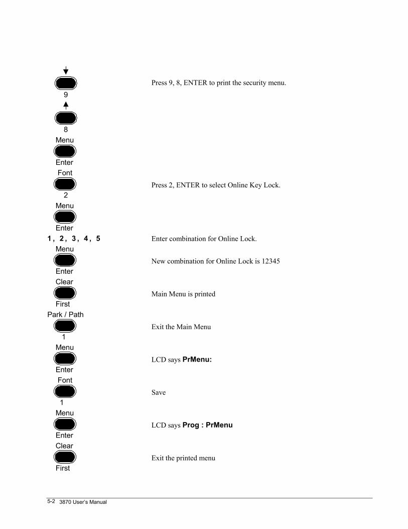
Example: Desired combination = 12345. With the printer offline, proceed as follows:
Menu
EnterLCD says Prog : Exit
8LCD says Prog : PrMenu
Menu
EnterMain menu is printed.
3870 User’s Manual5-2
9Press 9, 8, ENTER to print the security menu.
8 Menu
Enter Font
2Press 2, ENTER to select Online Key Lock.
Menu
Enter1 , 2 , 3 , 4 , 5 Enter combination for Online Lock. Menu
EnterNew combination for Online Lock is 12345
Clear
FirstMain Menu is printed
Park / Path
1Exit the Main Menu
Menu
EnterLCD says PrMenu:
Font
1Save
Menu
EnterLCD says Prog : PrMenu
Clear
FirstExit the printed menu

Control Panel Lockouts 5-3
Menu
EnterLCD shows format number.
If the printer is turned offline, then online, lights flash and a prompt to enter thecombination is displayed. Press ENTER following the last digit (1, 2, 3, 4, 5, Enter).
The Online Lock may be set from the host by sending an escape sequence. Details arein the ANSI chapter in the Programmer's Manual.
If the printer is locked online and the combination is unknown, send the escapesequence to either set the combination to 00000 (which removes the lock) or toanother number. Send the escape sequence to select ANSI before sending the escapesequence to change the lock to be sure the printer is in ANSI emulation.
If all else fails, remove the lock with an ISU; see "Reset the Printer – ISU”, Chapter 9.Be sure to have a printed configuration sheet available if an ISU is performed. An ISUerases all configuration information. It is recommended that a status report be printedif the printer is to be locked online or any time the configuration is changed.
Lock the Printed Menu
The printer can be set so that the printed menu will not work until a combination ofdigits is entered. Setting the combination is very similar to setting the combination forthe online lock described in the previous section. As many as 5 digits can be entered(the highest useable number is 65535) or enter 00000 to remove the lock. This can bedone from the Security menu, (option 98 on the main printed menu) or from the hostby sending an ANSI escape sequence. Details are in the ANSI chapter in theProgrammer's Manual.
Recovery from a lost combination is the same as for the online lock; the best methodis to send down a 00000 combination from the host. If an ISU is necessary, print out astatus sheet before resetting the printer.
Lock Various Keys
The security menu allows certain keys to work online or offline. The process is self-explanatory upon entering the security menu.
Formats 6-1
Chapter 6. Formats
What Is A Format ?
A format is a set of operating parameters, which are stored in nonvolatile RAM. Thereare four stored formats and one active format. All formats contain the followingoperating parameters:
Font Modes Top Print ReferenceCharacter Set Form Length Horizontal TabsCPI Top Margin Vertical TabsLPI Left Margin Left Print Reference
Each paper path has a stored format assigned to it. The same format can be assigned tomore than one paper path. Any format can be modified and renamed.
Why Use Formats?
Normally the printing parameters of the printer are controlled by the host, usually viathe application.
NOTE: If the printer can be changed from the application, it is not usually necessaryto modify format parameters.
Formats are very useful, however, when the host application cannot change theprinter’s operating parameters. In those instances, using formats is advisable ifparameters need to be changed often, such as to print on a variety of forms.
3870 User’s Manual6-2
The Active Format
The active format is a series of operating parameters, which the printer currently useswhen printing. As shipped, or upon an ISU of the printer, factory default parametersplus all the parameters of Format 4 become the active format. From this point on, anynumber of changes to the active format can be made. Events that can change the activeformat are:
commands from the hostLCD menu changesprinted menu changescontrol panel keys (CPI, LPI, etc.)selection of an alternative formatselection of a different paper path
Stored Formats
A stored format is a series of operating parameters held in the memory of the printer.This printer has four individual stored formats. Any one of these formats can becomethe active format. As shipped, or upon an ISU of the printer, the four stored formatsare set or revert to factory default parameters. From this point on, any number ofchanges to the four stored formats can be made.
Print All Format Information
Complete information about all formats can be printed using the LCD menu. To printall format information, select Prog : Utility from the main menu. The first twoselections under this submenu Prnt:Stat and PR Format will print all informationabout all formats. It is always a good idea to keep a current copy of the status andformats printout for future reference.
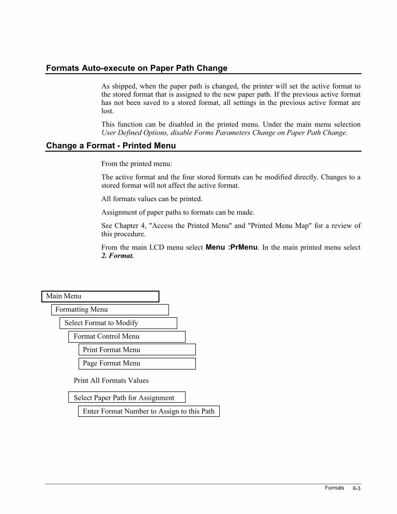
Formats 6-3
Formats Auto-execute on Paper Path Change
As shipped, when the paper path is changed, the printer will set the active format tothe stored format that is assigned to the new paper path. If the previous active formathas not been saved to a stored format, all settings in the previous active format arelost.
This function can be disabled in the printed menu. Under the main menu selectionUser Defined Options, disable Forms Parameters Change on Paper Path Change.
Change a Format - Printed Menu
From the printed menu:
The active format and the four stored formats can be modified directly. Changes to astored format will not affect the active format.
All formats values can be printed.
Assignment of paper paths to formats can be made.
See Chapter 4, "Access the Printed Menu" and "Printed Menu Map" for a review ofthis procedure.
From the main LCD menu select Menu :PrMenu. In the main printed menu select2. Format.
Main Menu
Formatting Menu
Select Format to Modify
Format Control Menu
Print Format Menu
Page Format Menu
Print All Formats Values
Select Paper Path for Assignment
Enter Format Number to Assign to this Path
3870 User’s Manual6-4
Save a Format from the Control Panel
The active format, along with any changes made, may be saved to any one of thestored formats with the Save option on the LCD menu.
Note: The format number that displays first when saving is the currently assignedformat.
Select the desired format by using the UP or DOWN arrows. Press ENTER to save.
Save a Format from the Host
The active format may be saved to any of the stored formats with an ANSI escapesequence. The ANSI term for this is CSS (Customer Setup Save). The printer must bein ANSI emulation to do this. (Emulations can be switched with escape sequences.Details are in the ANSI chapter in the Programmer's Manual.)
Select a Format from the Control Panel
A stored format can be changed to the active format using the FORNIAT key on thecontrol panel. With the printer offline, press and release the FORMAT key to cyclethrough the formats: ACTIVE, 1, 2, 3,4. Stop at the desired selection and wait aboutthree seconds for the function to time out. The selected format overwrites the activeformat and is assigned to the current paper path.
Selecting ACTIVE will exit the format function without changes.
Select a Format from the Host
A stored format may be selected from the host with an ANSI escape sequence. TheANSI term for this is CSU (Customer Setup Unsave). The printer must be in ANSIemulation to do this. (Emulations can be switched with escape sequences. Details arein the ANSI chapter in the Programmer's Manual.)
Formats 6-5
Select the Assigned Format from the Host
The format assigned to the current paper path may be selected with an ANSI escapesequence. The ANSI term for this is RIS (Restore to Initial State). The printer must bein ANSI emulation to do this. (Emulations can be switched with escape sequences.Details are in the ANSI chapter in the Programmer's Manual.)
Power Up to the Currently Assigned Format
As shipped, the printer will power up with the setting that was in the active formatwhen power was turned off. The printer may be set to power up with the formatassigned to the current paper path. This can be done in the printed menu SoftwareOption 14. See Chapter 4.
Rename a Format
As shipped, the printer will power up with the setting that was in the active formatwhen power was turned off. The printer may be set to power up with the formatassigned to the current paper path. This can be done in the printed menu SoftwareOption 14. See Chapter 4.
An alphanumeric name of up to 16 characters can be assigned to each of the fourstored formats and also to the active format. This can only be done from the host usingANSI escape sequences. See the ANSI chapter of the Programmer's Manual.
The stored format names are saved in nonvolatile RAM until changed by the user orreset by ISU.
Note: A user-defined name for the active format will be lost when a stored format iscalled up.
LCD Message Display
A one-time message to be displayed on the printer's LCD can be downloaded. Thiswill be overwritten by the next action that would otherwise update the display.
The printer must be in ANSI emulation to download format names and messages.(Emulations can be switched using escape sequences. Details are in the ANSIchapter of the Programmer's Manual.)
3870 User’s Manual6-6
Linking Emulations to Formats
When the printer is shipped, and again at ISU, none of the stored formats is linked toan emulation. In the ISU condition of the printer, the current emulation remainscurrent when a stored format is invoked. This is true whether the stored format isinvoked by a paper-path change, by the control panel Format key, or by ANSI CSUcommand.
Any supported emulation can be assigned (linked) to any of stored formats 1-4. Theonly way that a linkage can be either assigned or modified is via the printed menu. Alinkage thus established is the only stored parameter that is immune from being over-written if the current state of the printer is saved to the affected format. This is truewhether the current state is saved by the SAVE function on the LCD menu, or byANSI CSS command.
LCD Head Gap Menu 7-1
Chapter 7. LCD Head Gap MenuThe print head gap may be controlled from the LCD menu. Print head gap is thedistance from the print head nozzle to the striker bar. Maintaining the correct printhead gap is critical to good print quality and print head life. If the gap is too small,characters will smudge and the ribbon may snag on the print wires. If the gap is toolarge, the print quality will be poor, the printer will be noisier, and print head wearspeeds up.
As shipped, the printer is set to automatically adjust the print head gap each time aform is loaded.
Semiautomatic head gap adjustment allows preset print head gaps to be applied to anypaper path.
Semiautomatic head gap adjustment may be used in one paper path and automaticprint head gap adjustment used in another.
From the LCD main menu Prog : Utility, select Utility:Prnt Stat to print a statusthat shows the print head gap mode and offset settings for the active format. SelectUtilit:PR Format to print the same information for the four stored formats.
Print head gap control is available only from the LCD menu. Neither host commandsnor the printed menu offer any control over the print head gap.
3870 User’s Manual7-2
Change Ribbon
From the LCD main menu Prog : Head Gap, select Head G:Ribbn Chg to openthe print gap for removing and installing a ribbon.
Because the print head gap is opened whenever paper is parked, it may be moreconvenient to park the paper when removing and installing a ribbon.
Pros and Cons of Auto Head Gap Adjust
The advantage of auto head gap is that the operator never needs to adjust the printhead gap, except perhaps as the ribbon wears. Forms of various thicknesses may beloaded into the different paper paths and the print head gap will be adjusted to matchthe form.
The disadvantage of auto head gap is that the printer makes a mark on the first formwhen it senses the thickness. This may be a problem when using preprinted,prenumbered forms (such as payroll checks), or if paper paths are changed frequently.
How Auto Head Gap Adjust Works
When set to Auto Head Cap Adjust (as shipped), loading a paper path will cause thefollowing actions:
Any time here is no paper under the print head, the print head will back away from thestriker bar as far as possible.
Pressing the FF / Load key will load paper in the selected path to the top printreference.
The carriage moves the print head to a position over the paper-out sensor.
The print head moves in and presses with a known force against the ribbon toestablish the thickness of the ribbon / paper combination.
The print head moves back a certain distance and then forward again for half thatdistance. This minimizes the effects or mechanical backlash on the accuracy of theadjustment.
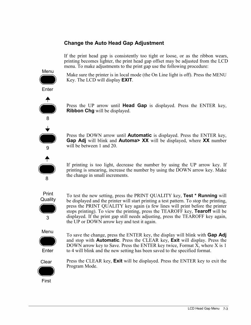
LCD Head Gap Menu 7-3
Change the Auto Head Gap Adjustment
If the print head gap is consistently too tight or loose, or as the ribbon wears,printing becomes lighter, the print head gap offset may be adjusted from the LCDmenu. To make adjustments to the print gap use the following procedure:
Make sure the printer is in local mode (the On Line light is off). Press the MENUKey. The LCD will display EXIT.
Press the UP arrow until Head Gap is displayed. Press the ENTER key,Ribbon Chg will be displayed.
Press the DOWN arrow until Automatic is displayed. Press the ENTER key,Gap Adj will blink and Automa> XX will be displayed, where XX numberwill be between 1 and 20.
If printing is too light, decrease the number by using the UP arrow key. Ifprinting is smearing, increase the number by using the DOWN arrow key. Makethe change in small increments.
To test the new setting, press the PRINT QUALITY key, Test * Running willbe displayed and the printer will start printing a test pattern. To stop the printing,press the PRINT QUALITY key again (a few lines will print before the printerstops printing). To view the printing, press the TEAROFF key, Tearoff will bedisplayed. If the print gap still needs adjusting, press the TEAROFF key again,the UP or DOWN arrow key and test it again.
To save the change, press the ENTER key, the display will blink with Gap Adjand stop with Automatic. Press the CLEAR key, Exit will display. Press theDOWN arrow key to Save. Press the ENTER key twice, Format X, where X is 1to 4 will blink and the new setting has been saved to the specified format.
Press the CLEAR key, Exit will be displayed. Press the ENTER key to exit theProgram Mode.
Menu
Enter
8
9
8
3
PrintQuality
Menu
Enter
Clear
First
3870 User’s Manual7-4
Finish by tearing off the excess paper, parking the paper, reload the paper and senda test to the printer. If satisfactory, the adjustment is complete. If not, repeat thissection to adjust the print gap further.
Before Saving to a Format
If anything other than print head gap settings is to be saved, the printed menuoffers the best approach.
Print head gap settings may only be changed from the LCD menu. The only wayto save print head gap settings to one of the stored formats is to modify the activeformat and save it to the desired stored format.
With paper loaded in the desired paper path, note carefully the format numbershown on the LCD. This is the format assigned to the current paper path. Press andrelease the FORMAT key to select the desired format. Print head gap settings maynow be made.
Save the Setting to a FormatPress the FIRST key to go back to the LCD main menu. Use the DOWN ARROW tostep to Prog:Save. The format assigned to the current paper path will be shown onthe LCD. Press the ENTER key to save the current state of the printer to the numbershown on the LCD.
As in the case of other user-adjustable parameters, changes to the head gap settingsapply initially to the active format. The active format is normally maintained throughpower on and power off, but will be overwritten if the paper path is changed or if adifferent format is loaded by the control panel or the host.
LCD Head Gap Menu 7-5
Semiautomatic Head Gap Adjust
To avoid a mark on the first form each time a paper path is loaded, selectsemiautomatic head gap adjust for that paper path. Different fixed gap settings may beassigned to any of the paper paths.
With paper loaded in the desired paper path, note carefully the format number shownon the LCD. This is the format assigned to the current paper path. Press and releasethe Format key to select the desired format. Print head gap settings may now be made.
From the LCD main menu Prog : Head Gap, select Head G:Semi-Auto. Thenumbers in this menu are backwards from the numbers in the Auto Head Gap Offsetmenu. In semiauto head gap adjust, the smaller the number, the larger the print headgap.
Pressing the UP ARROW or DOWN ARROW keys repeatedly will scroll through alist of settings that include selections for 5-part, 6-part etc. These are good startingpoints for various multipart forms.
Press the PRINT QUALITY key to start a test pattern. Press the key again to stop thetest. Press the TEAR OFF key to view the printout.
Make small adjustments until optimum print quality is obtained.
To save the changes to the form assigned to the current paper path, selectProg : Save from the main LCD menu and press Enter.
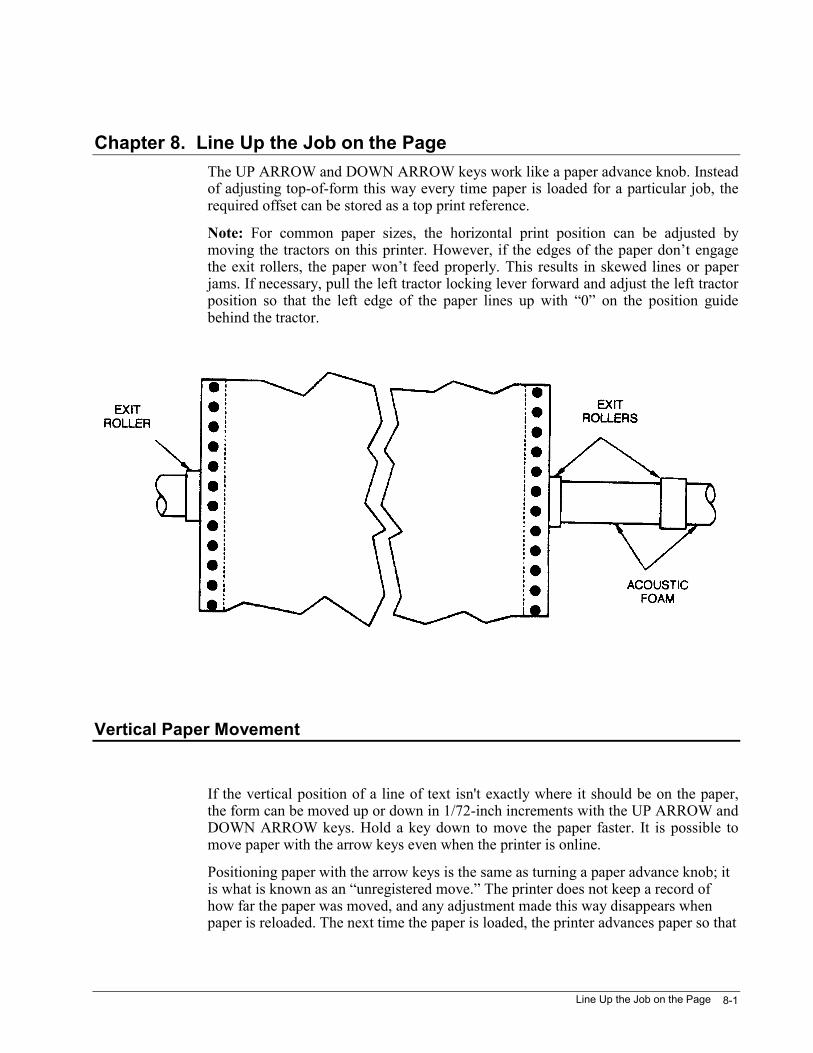
Line Up the Job on the Page 8-1
Chapter 8. Line Up the Job on the PageThe UP ARROW and DOWN ARROW keys work like a paper advance knob. Insteadof adjusting top-of-form this way every time paper is loaded for a particular job, therequired offset can be stored as a top print reference.
Note: For common paper sizes, the horizontal print position can be adjusted bymoving the tractors on this printer. However, if the edges of the paper don’t engagethe exit rollers, the paper won’t feed properly. This results in skewed lines or paperjams. If necessary, pull the left tractor locking lever forward and adjust the left tractorposition so that the left edge of the paper lines up with “0” on the position guidebehind the tractor.
Vertical Paper Movement
If the vertical position of a line of text isn't exactly where it should be on the paper,the form can be moved up or down in 1/72-inch increments with the UP ARROW andDOWN ARROW keys. Hold a key down to move the paper faster. It is possible tomove paper with the arrow keys even when the printer is online.
Positioning paper with the arrow keys is the same as turning a paper advance knob; itis what is known as an “unregistered move.” The printer does not keep a record ofhow far the paper was moved, and any adjustment made this way disappears whenpaper is reloaded. The next time the paper is loaded, the printer advances paper so that
3870 User’s Manual8-2
the top edge of the physical form lines up with the top wire of the print head. Thedistance that paper moves during a load operation is the “load-length distance”.
What is a Print Reference?
The top print reference is similar to a top margin, and the left print reference is similarto a left margin. However, there are critical differences between margins and printreferences that should be understood before deciding which one to set.
Set a Top Print Reference
Assume that a particular form must be adjusted the same number of increments withthe UP ARROW key every time that form is loaded. This step may be eliminated bysaving an offset value to the load length distance so the form will automatically beproperly positioned when it is loaded. This is the Format parameter "Top PrintReference."
Top print reference can be set from the LCD menu, or from the printed menu. It iseasier to set it from the printed menu.
Different top print references can be included in stored formats, but there are twoaspects of setting the top print reference that are not obvious:
1. The top print reference cannot be modified in the active format. If a top printreference is not saved to a stored format, it never takes effect.
2. After saving a top print reference to a stored format, it will not take effect untilthe next time paper is loaded. If a top print reference is saved to a stored format,the operator must park and reload the paper in order for the top print referenceto take effect.
There must always be blank space at the bottom of a form that is equal to or greaterthan the top print reference; otherwise, the printer will print across the perforation andonto the next form.
If a non-zero value is set for the top print reference, the tear-off distance in theaffected format may need to be changed accordingly (see next section).
Line Up the Job on the Page 8-3
Set the Tear Off Distance
1. Park and reload paper so the top print reference, if set, will take effect.
2. With paper at top-of-form, press the TEAR OFF key. The printer advances paperaccording to the current tear-off distance.
3. Use the UP ARROW and DOWN ARROW keys to set the desired tear-offdistance.
4. Press ENTER.
5. Press the TEAR OFF key again, or wait for the tear-off function to time out.
The new tear-off distance is now stored in the currently selected format.
Set a Left Print Reference
A left print reference can be set either from the print reference option on the LCDmenu or from the printed menu. The menus expect values to be entered in inches andhundredths (unless the units of measure have been changed to decipoints via softwareoptions on the printed menu).
In contrast to the top print reference, the left print reference can be modified in theactive format. Different left print references can be saved in each of the four storedformats.
CAUTION
Do not set a left print reference that will cause printing off the right side of paper.This will damage the printer.
3870 User’s Manual8-4
Local Margins are Tricky
It is a good idea to set a right margin equal to the form width. If the host gets confusedand sends a long line of data, it is not desirable to print off the right-hand edge of thepaper.
All of the emulations have control sequences to set both horizontal and verticalmargins, but very few printer drivers use them. Typically, an application assumes thatno margins are set at the printer and sends spaces and line feeds to effect thehorizontal and vertical margins specified. Some applications clear all printer marginsbefore sending any printable data.
If a margin is desired and it can be set from the application, set it from the application.If either horizontal or vertical margins are set locally to position a job on the page orto skip over perforations, they may work with one application and not with the next.
Use Top Print Reference or Top Margin?
The selection of a top print reference or a top margin depends upon the methods thatthe application uses for paper movement. A top print reference is used when printingneeds to start in a different location than where the paper is initially loaded. A topmargin also adds space to the top of a print job, but it may have a different effect,depending upon the method used for moving paper to the top of the next form.
Many applications don't send form feeds to move from one form to the next, butinstead they send enough line feeds to get from the last printed line on one form to thefirst printed line on the next.
If a top margin is set at the printer and the application is sending form feeds to movefrom one form to the next, the top margin will work as expected. If the application issending line feeds to move from one form to the next, however, the top margin willaccumulate. The first printed line on each successive form will move down the pageby the amount of the top margin.
To summarize, a top margin adds blank space beyond what is sent by the host. A topprint reference, on the other hand, adds no blank space but simply moves printingdown on the form.
Line Up the Job on the Page 8-5
Use Left Print Reference or Left Margin?
Setting a non-zero value for the left print reference moves printing to the right on thepaper.
When deciding whether to set a left margin or a left print reference, note that if a leftmargin is set at the printer and the application sends horizontal tabs, the position ofthe horizontal tabs relative to the leftmost character on the paper may no longer becorrect. This depends on how the application sets tabs and whether horizontal tabswere set before or after the left margin was set.
To summarize: if it is desired to limit the number of characters that can be placed on aline, then use left and right margins. If the horizontal position of printing on the paperneeds to be changed, use the left print reference.
Load Length Adjustment
Load length is the distance that a form is advanced beyond the point of actuation ofthe paper-out switch when that form is loaded following an ISU. The load lengthadjustment is correct when, following an ISU, the absolute top edge of the form isloaded aligned with the topmost print wire on the print head.
The load length adjustment is carefully set at the factory and should not need to bechanged unless a user has inadvertently changed the setting during an ISU, or thepaper-out switch has been replaced. If the load length adjustment is high, printing onthe striker bar may occur during a low-paper condition. If low, the printer may printon the striker bar above the first line of the first form. An error in either directioncompromises the accuracy of any vertical settings relative to the absolute top edge ofthe form.
The following procedure requires that the ISU be performed twice. This is not amistake; it is the most straightforward way to make sure any print references orvertical margins get cleared. It is important that the load length adjustment beperformed as described below. DO NOT use the load length adjustment to establishany top margin, however small.
1. Turn printer power off.
2. Press and hold the control panel keys numbered 1 and 2.
3870 User’s Manual8-6
3. While holding keys 1 and 2, turn the printer power on. Continue to hold untilthe printer powers up with the FAULT light flashing.
4. Release keys 1 and 2.
5. Press the CLEAR key to acknowledge the ISU.
6. With the printer offline, press the PARK key to park paper in the current path;then press the FF/ LOAD key to reload it. This positions the absolute top-of-form according to the load length adjustment.
7. Press the CLEAR key.
8. The topmost print wire on the print head should be positioned just below theabsolute top edge of the form. This can be verified by printing a line of testpattern as described in "Print a Test Pat- tem", Chapter 2, or by sending a line ofdata from the host. The topmost printed dot should be entirely on the form butno more than 1/32 inch below the absolute top edge of the form. If this is true,no adjustment is necessary. If not true, then proceed as follows:
9. Park paper and reload it.
10. Turn printer power off.
11. Press and hold the control panel keys numbered 1 and 2.
12. While holding keys 1 and 2, turn the printer power on. Continue to hold untilthe printer powers up with the FAULT light flashing.
13. Release keys 1 and 2.
14. While the FAULT light is flashing, use the UP- and DOWN-ARROW keys toalign the absolute top edge of the form with the topmost wire on the print head.
15. Press the CLEAR key to acknowledge the ISU.
Power Up and Reset 9-1
Chapter 9. Power Up and ResetThis printer stores user-adjustable parameters, from print quality to bar codeexpansions, in an area of nonvolatile RAM known as the active format.
The State of the Printer on Power-up
When the printer is shipped, it is configured so that it powers up to the active format.In other words, every time the printer is turned on, it has the same settings as when itwas last turned off. If the last thing that was printed before turning power off was at12 CPI and 4 LPI, when the printer is turned back on, it prints at 12 CPI and 4 LPIuntil the user or the host tells it otherwise.
As an alternative, if it is desired that the printer power up to the settings in thecurrently selected format, go to the printed menu and set Software Option 14 to ENB.
Reset the Printer - ISU
The printer can be set to the way it was when it left the factory by performing aprocedure known as an "ISU.' When the printer is shipped, the emulation is set toANSI. Print parameters are set to emulation-defined defaults. Interface controls andother print-engine specific parameters are set to generic values. These factory settingsare the Initial SetUp, and the procedure that restores these settings is an "ISU.' If theISU is performed on the printer, then nearly every adjustable parameter stored innonvolatile RAM is replaced with default values from ROM.
An ISU is somewhat analogous to rebooting a computer. If the printer seems to belocked up and recycling power doesn't free it, try an ISU.
An ISU can cost some work if complex setups are stored in the printer. The storedformats and format-to-paper-path assignments are reset to factory settings alongwith nearly everything else. If possible, before performing an ISU, print a statussheet and a format sheet. To perform an ISU:
1. With paper loaded in the current path, turn the printer power off.
2. Press and hold the PARK/ PATH and FONT keys (1 and 2).
3870 User’s Manual9-2
3. While holding these two keys, turn the printer power on. Continue to hold thekeys down until the printer turns on with the FAULT light flashing.
4. Release the PARK/ PATH and FONT keys. Do not press the UP ARROW orDOWN ARROW keys at this time.
5. Press the CLEAR key to acknowledge the ISU. The FAULT light stops flashingand, in the absence of any printer faults, goes out.
After a Software Upgrade
Note: Be sure to ISU the printer if any ROMs are changed or the PHPM board isremoved and reinstalled. If this is not done the printer may lock up.
After an ISU
The following items may need to be restored after an ISU:
1. Any option that is enabled from the hardware options menu (item 99 on themain printed menu).
2. The emulation if using anything but the defaults.
3. Any straps that have been modified (software options or emulation-dependentoptions).
4. Formats 1-4 may need to be programmed.
Note: User parameters that are not reset are the flight-time compensation adjustment(see "Adjust the Flight-Time Compensation", Chapter 11) and the load lengthadjustment (see Chapter 8).
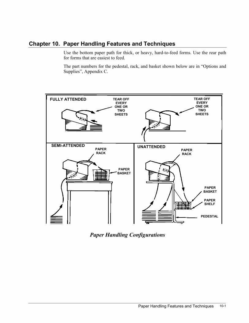
Paper Handling Features and Techniques 10-1
Chapter 10. Paper Handling Features and TechniquesUse the bottom paper path for thick, or heavy, hard-to-feed forms. Use the rear pathfor forms that are easiest to feed.
The part numbers for the pedestal, rack, and basket shown below are in “Options andSupplies”, Appendix C.
Paper Handling Configurations
SEMI-ATTENDEDPAPERRACK
PAPERBASKET
UNATTENDEDPAPERRACK
PAPERSHELF
PAPERBASKET
TEAR OFFEVERY
ONE ORTWO
SHEETS
TEAR OFFEVERY
ONE ORTWO
SHEETS
FULLY ATTENDED
PEDESTAL
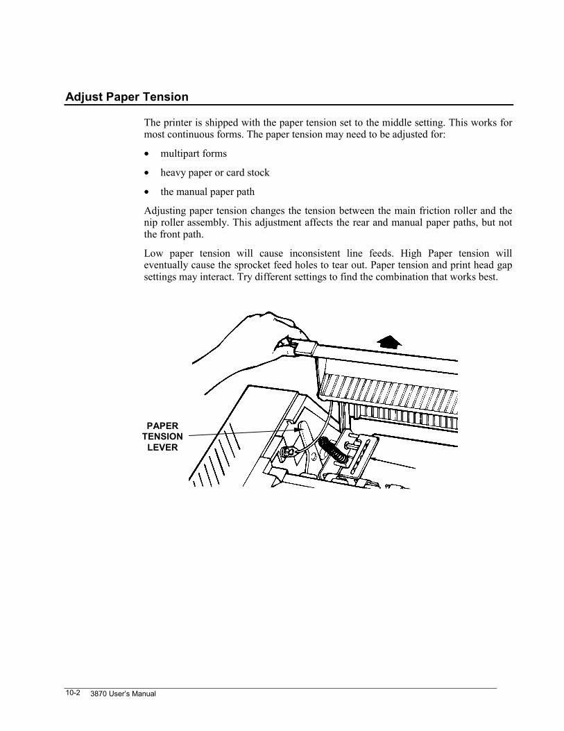
3870 User’s Manual10-2
Adjust Paper Tension
The printer is shipped with the paper tension set to the middle setting. This works formost continuous forms. The paper tension may need to be adjusted for:
• multipart forms
• heavy paper or card stock
• the manual paper path
Adjusting paper tension changes the tension between the main friction roller and thenip roller assembly. This adjustment affects the rear and manual paper paths, but notthe front path.
Low paper tension will cause inconsistent line feeds. High Paper tension willeventually cause the sprocket feed holes to tear out. Paper tension and print head gapsettings may interact. Try different settings to find the combination that works best.
PAPERTENSION
LEVER

Paper Handling Features and Techniques 10-3
Check the Chart The chart shows starting points for the paper tension adjustment. Ahigher number increases the tension; moving the lever toward therear of the printer.
Open the rear door
Pull the paper tensionadjust level away fromthe side frame ...
To disengage the lever pin from the hole in the side frame.
Move the lever to thenew position.
Make sure the level pin is in one of the four holes that serve asdetents.
Lever Position Type of Paper
1. (toward the front of the printer) Use as needed.
2. (middle position) Continuous feed: 15-24lb.
Manual feed: light weight cut sheets
3. (toward the rear of the printer) Manual feed: envelopes, heavy cut sheets
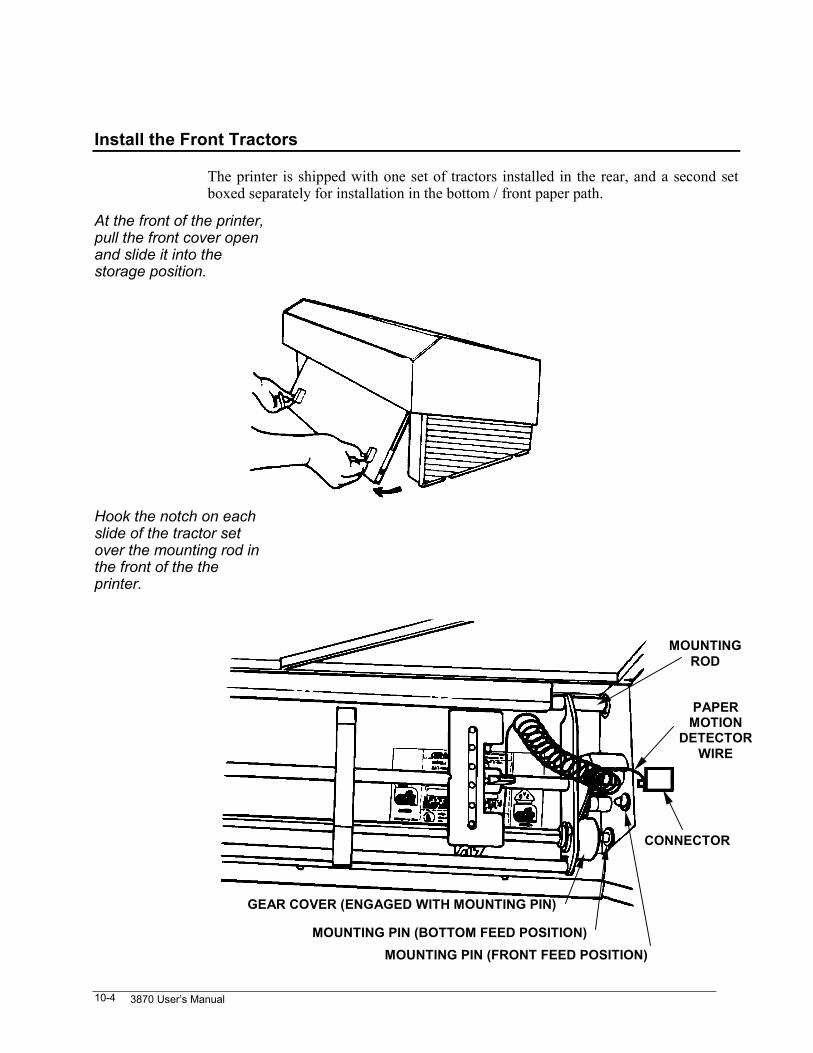
3870 User’s Manual10-4
Install the Front Tractors
The printer is shipped with one set of tractors installed in the rear, and a second setboxed separately for installation in the bottom / front paper path.
At the front of the printer,pull the front cover openand slide it into thestorage position.
Hook the notch on eachslide of the tractor setover the mounting rod inthe front of the theprinter.
GEAR COVER (ENGAGED WITH MOUNTING PIN)
PAPERMOTION
DETECTORWIRE
CONNECTOR
MOUNTING PIN (BOTTOM FEED POSITION)MOUNTING PIN (FRONT FEED POSITION)
MOUNTINGROD
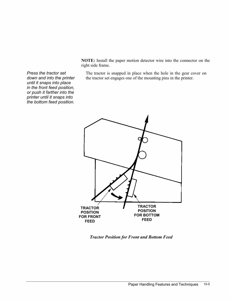
Paper Handling Features and Techniques 10-5
NOTE: Install the paper motion detector wire into the connector on theright side frame.
Press the tractor setdown and into the printeruntil it snaps into placein the front feed position,or push it farther into theprinter until it snaps intothe bottom feed position.
The tractor is snapped in place when the hole in the gear cover onthe tractor set engages one of the mounting pins in the printer.
Tractor Position for Front and Bottom Feed
TRACTORPOSITION
FOR BOTTOMFEED
TRACTORPOSITION
FOR FRONTFEED
3870 User’s Manual10-6
Switch Between Front Feed and Bottom Feed
The tractors may be easily switched between front and bottom feed. The tractorassembly swings from hooks at the top.
At the front of the printer,pull the bottom of theacoustic door outwardand slide the top inwardinto the storage position.
Find the gear covers. The bottom tractor shaft is square with a gear cover on each end.Spring-loaded balls in each gear cover engage locating pins in thesides of the printer.
Front feed to bottomfeed
Push down firmly on the square shaft near the ends. The assemblywill pop free of the locating pins. Swing the assembly down until itsnaps into the locating pins for bottom feed. Wiggle the ends of theassembly to ensure the pins are engaged.
Bottom feed to front feed Pull up firmly on the square shaft near the ends. The assembly willpop free of the locating pins. Swing the assembly up until it snapsinto the locating pins for front feed. Wiggle the ends of theassembly to make sure the pins are engaged.
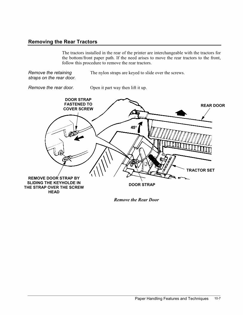
Paper Handling Features and Techniques 10-7
Removing the Rear Tractors
The tractors installed in the rear of the printer are interchangeable with the tractors forthe bottom/front paper path. If the need arises to move the rear tractors to the front,follow this procedure to remove the rear tractors.
Remove the retainingstraps on the rear door.
The nylon straps are keyed to slide over the screws.
Remove the rear door. Open it part way then lift it up.
REMOVE DOOR STRAP BYSLIDING THE KEYHOLDE IN
THE STRAP OVER THE SCREWHEAD
DOOR STRAP
DOOR STRAPFASTENED TOCOVER SCREW
REAR DOOR
TRACTOR SET
Remove the Rear Door
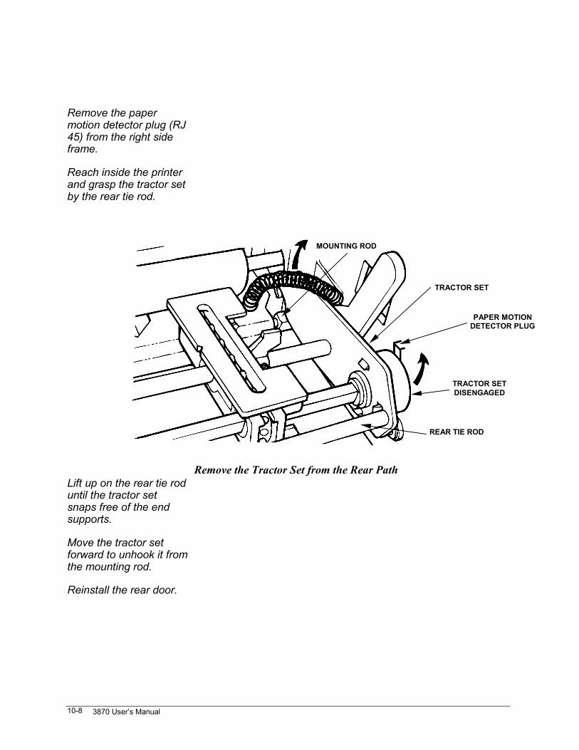
3870 User’s Manual10-8
Remove the papermotion detector plug (RJ45) from the right sideframe.
Reach inside the printerand grasp the tractor setby the rear tie rod.
Lift up on the rear tie roduntil the tractor setsnaps free of the endsupports.
Move the tractor setforward to unhook it fromthe mounting rod.
Reinstall the rear door.
Remove the Tractor Set from the Rear Path
MOUNTING ROD
TRACTOR SET
TRACTOR SETDISENGAGED
REAR TIE ROD
PAPER MOTIONDETECTOR PLUG
Paper Handling Features and Techniques 10-9
Change Paper Paths from the Control Panel
Tear off any forms in thecurrent path.
The printer will retract up to one and one half times the formlength or six inches whichever is greater.
Park / Path
1The printer parks the form in the current paper path.
Press and release thePark/Path key until theLCD shows the desiredpaper path.
Wait three seconds forthe function to time out.
F a u l t : P a p e r O u t
FF / Load
6If there is paper in the selected path, the printer will load a form.
If the LCD still saysFault:Paper Out.
If a form is loaded, press the Clear key. As shipped, the printer willclear a paper out fault when a form is loaded. If software option 13is disabled, the fault must be cleared from the control panel.
3870 User’s Manual10-10
Change Paper Paths from the Host
Front or rear paper paths may be selected from the host. The printer must be in ANSIemulation to do this. Emulations may be switched using escape sequences. Details arein the Programmer's Manual.
If the paper shear option is not being used, forms may need to be torn off before thehost can make a paper path change. To insure that this happens:
• Send a form feed before sending a command to change paper paths.
• Put a pause in the program and a prompt to tear off paper.
• In the printed menu, if auto tear off is selected under printing modes in the formatmenu, the paper will advance to the tear off position after a form feed.
• In the printed menu, set user defined option Paper Tearoff Timeout to disabled.This causes the printer to go busy while paper is in the tearoff position. This willmake sure that the current form gets torn off before a remote paper path changecan be made.
When the paper path is changed from the host, the printer win park paper in thecurrent path by retracting six inches of paper or one half of the current form length,which ever is greater. This contrasts to the one and one-half form lengths that will beparked from the control panel.
If more paper than this remains, the printer will cancel the paper park and move thepaper back to its original position. No more data will be printed and both the controlpanel and interface will indicate a fault condition.
Recover from a Remote Path Change Failure
If the printer cannot change paper paths because there is too much paper in the currentpath to park, the LCD will indicate a paper jam. To recover, press the Tear Off keyand tear off the form in the current path.
Press Park/ Path to load the new path and print any data sent to the new paper path.
Paper Handling Features and Techniques 10-11
Auto Load on Paper Out
The printer may be set so that when paper runs out in the front/bottom or rear paperpaths, it will automatically load paper from the other paper path. Both sets of tractorsmust be installed to do this.
This feature is controlled by Two Box Option, Auto-load of Continuous Forms underUser Defined Options on the printed menu. The printer is shipped with this optiondisabled.
Multipart Forms
When printing multipart forms:
Use the bottom paper path for very thick or heavy forms. When printing on differentweight forms, use the rear paper path for the lighter forms.
If multipart forms are to be printed from the rear path, make sure the paper is pulled astight between the tractors as possible without causing the holes to tear out.
Check the paper tension adjust lever for the correct setting; see “Adjust PaperTension” in this Chapter.
Select either the WD Gothic DP or the WD Gothic LQ font. The WD (wide) fontsmake better carbon copies. Fonts can be selected directly with the font key, from theLCD menu, or from the printed menu.
Select MultiPart to reduce carriage speed and increase print impact. From theProg:SpcMod LCD submenu, select SpcMod:MultiPart. From the printed menu,go through the Format menu to the Printing Mode submenu and select Multi partforms mode (increased impact). Select MultiPart mode downline via the Straps andOptions escape sequence, store it in a format, and recall the format with an escapesequence. See the ANSI chapter in the Programmer’s Manual for details.
As shipped, the printer is set to move paper at 15 inches per second. If the printer istearing the sprocket holes, or otherwise pulling forms apart during form feeds, reducethe paper speed to 5 inches per second. On the printed menu, go through the Formatmenu to the Select Printing Mode submenu. Like Multipart Mode, this option can beselected downline via the Straps and Options escape sequence.
3870 User’s Manual10-12
Manual Paper Path
Cut sheets and envelopes may be printed one at a time using the manual paper path.The manual paper path guides snap onto the front part of the rear cover allowing easyloading of cut sheets and envelopes.
When printing cut sheets, allow at least a 1/6-inch margin at the top and a 1/2-inchmargin at the bottom of the page. Printing closer than 1/2 inch to the bottom of thepage, will cause a paper-out fault. At 6 LPI, a paper-out fault will occur after the 64thline.
For this reason, sending line feeds to advance paper to the next form will not workwith cut sheets in the manual paper path.
Also, printing on the very top of a cut sheet may cause inconsistent print quality onthe first line of the form.
To use the manual paper path:
With the printer offline,
Park / Path
1Press Park/Path the currently loaded form.
Park / Path
1Press and release Park/Path until Path : Manual appears in theLCD.
P a t h : M a n u a l
Set the paper tensionadjustment to 2.
See “Adjust Paper Tension” earlier in this chapter.
Adjust the paper guidesfor width and position.
If the printer is set for 0 left margin and 0 left print reference,lining up the arrow on the left paper guide with the arrow on thetop door will result in a 1/2-inch left margin.
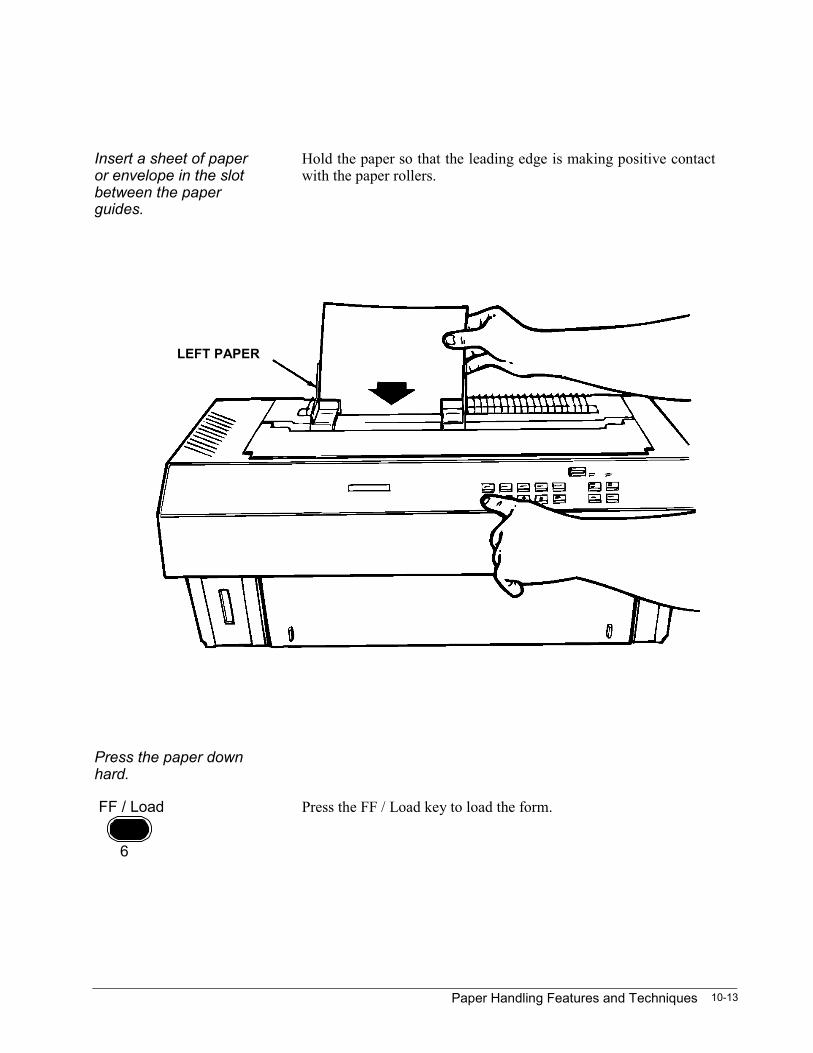
Paper Handling Features and Techniques 10-13
Insert a sheet of paperor envelope in the slotbetween the paperguides.
Hold the paper so that the leading edge is making positive contactwith the paper rollers.
Press the paper downhard.
FF / Load
6
Press the FF / Load key to load the form.
LEFT PAPER
3870 User’s Manual10-14
Manual Path Auto-loads the Next Sheet
With the manual paper selected, the printer will automatically do a paper load after aform feed. During a paper load, the paper feed system slowly advances paper to thetop print position. The maximum distance paper will load is seven inches.
While the paper system is advancing following a form feed, slide a new form into themanual path. The paper will be loaded to the correct position.
If a new form is not loaded before the paper feed system advances its maximumseven inches, just press FF/ Load.
To use this feature, the application must send a form feed after every page orenvelope.
Single Envelopes
Envelopes may be printed one at a time using the manual paper path. There are someconstraints regarding printing single envelopes. They are:
• 24-lb maximum envelope stock.
• No windows.
• Beware of wide overfolds.
• Beware of large or embossed logos.
The very top of the envelope can not be printed on reliably. A top margin as little asone inch may be enough. This is one of the few instances when setting a top marginfrom the control panel is recommended.
If automatic head gap adjustment is used, the printer will sense the thickness of theenvelope at the top edge and printing may smudge on the overfolds. If this happens, itmay be necessary to use semiautomatic print head gap adjust. Expect to use severalenvelopes to find the combination of paper tension and print head gap that providesoptimum print quality. Start with a paper tension setting of 3.
Paper Handling Features and Techniques 10-15
Continuous Envelopes
Continuous envelopes that are packaged on sprocket-feed strips should be fed fromthe BOTTOM paper path.
Any continuous envelopes designed for impact-matrix printing should work well inthis printer, but test an envelope design before committing to it. The overfolds ofenvelopes can be a problem. The print gap must be set so the thickest part of theenvelope doesn't get smudged; this is more print gap than is needed for optimum printquality.
For problem envelopes, experiment with the multipart setting to reduce carriage speedand increase print impact. This is in the Special Modes LCD submenu. On the printedmenu, go through the Format menu to the Select Printing Mode submenu.
Clean Up After Nonbonded Paper
If the paper has a high lint or dust content, paper dust may combine with the ink onthe ribbon to form a paste. This paste may accumulate in the ribbon cartridge and onthe ribbon guide. It may also build up on the face of the print head and restrict themovement of the print wires. The following symptoms appear after a short operatingperiod:
• fuzzy characters
• intermittent gaps or missing dots
• light printing occurring before the expected end-of-life of the ribbon
Correct this as follows:
Turn the printer off.
Remove the ribboncartridge.
Clean the ribbon guide. Use a foam swap dipped in rubbing alcohol to wipe awayaccumulated paste. Don’t use rubbing alcohol with additives likewitch hazel or wintergreen.
Clean the face of theprint head.
Gently wipe away accumulated paste using a foam swab dipped inrubbing alcohol. Loosen the print head mounting screws to tip theprint head up so it’s more accessible, but don’t unplug theconnector.
Secure the print head.
Replace the ribbon.

3870 User’s Manual10-16
Tips for Continuous Forms
• When using a table or desk for the printer, position the printer and paper supply sothat the paper does not drag on the edge of the surface as it enters the printer. Theprinter should be as close to the edge of the table or desk as possible.
• Place the paper box so that paper flows out of it without dragging on the sides ofthe box.
• Each time a new box of paper is started, bend the flaps down and tape them to thesides of the box or cut them off. Also pull the sides of the box away from thepaper stack to allow clearance.
• As the paper supply begins to run low, remove the remaining paper stack from thebox and place it beneath the printer.
• If printing bar codes, stiff forms, or thick multipart forms, place the paper supplybeneath the printer and use the bottom paper path.
Paper Handling Features and Techniques 10-17
• When printing graphics or bar codes, don’t use tear-off to view the page. Papermoves backwards during a tear-off cycle, and sometimes this causes a tiny error invertical registration. The error is not noticeable when printing text, but an error assmall as 1/72 inch shows up as a horizontal stripe in graphics or bar codes.
CAUTION
When printing continuous forms, don’t attempt to back theperforation past the print head. This may cause the paper
to snag on the print head. This is likely to occur whenusing tear-off to view a form.
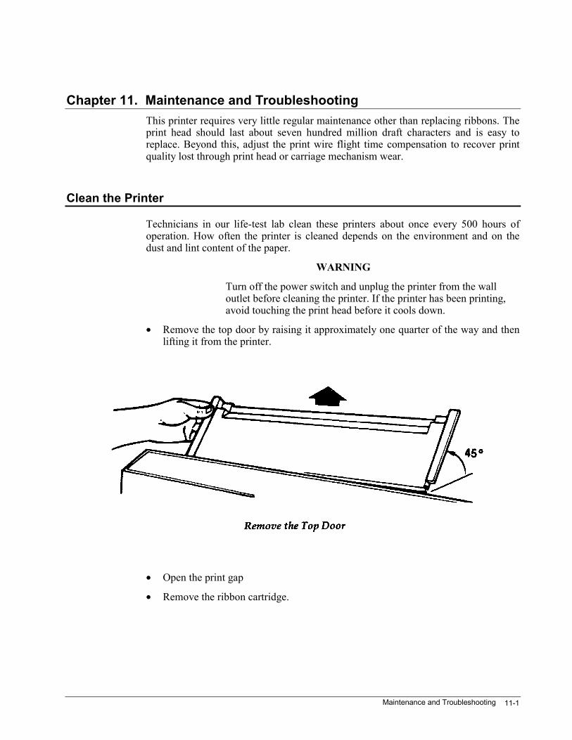
Maintenance and Troubleshooting 11-1
Chapter 11. Maintenance and TroubleshootingThis printer requires very little regular maintenance other than replacing ribbons. Theprint head should last about seven hundred million draft characters and is easy toreplace. Beyond this, adjust the print wire flight time compensation to recover printquality lost through print head or carriage mechanism wear.
Clean the Printer
Technicians in our life-test lab clean these printers about once every 500 hours ofoperation. How often the printer is cleaned depends on the environment and on thedust and lint content of the paper.
WARNING
Turn off the power switch and unplug the printer from the walloutlet before cleaning the printer. If the printer has been printing,avoid touching the print head before it cools down.
• Remove the top door by raising it approximately one quarter of the way and thenlifting it from the printer.
• Open the print gap
• Remove the ribbon cartridge.
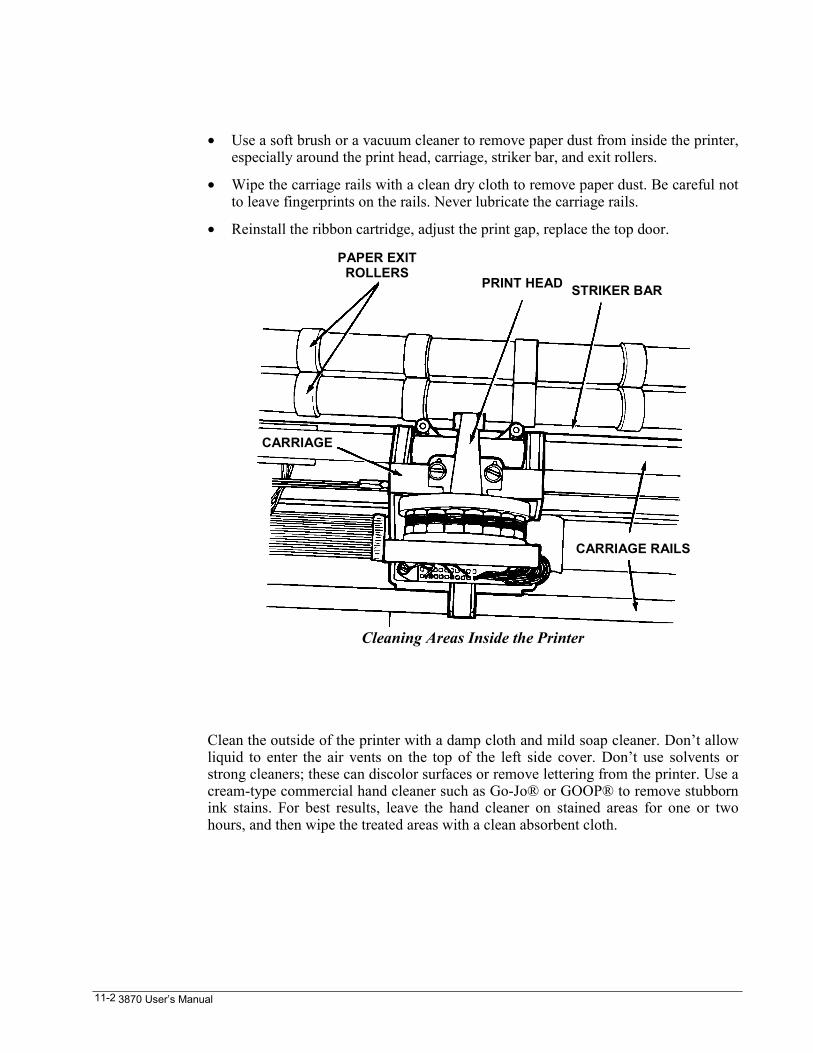
3870 User’s Manual11-2
• Use a soft brush or a vacuum cleaner to remove paper dust from inside the printer,especially around the print head, carriage, striker bar, and exit rollers.
• Wipe the carriage rails with a clean dry cloth to remove paper dust. Be careful notto leave fingerprints on the rails. Never lubricate the carriage rails.
• Reinstall the ribbon cartridge, adjust the print gap, replace the top door.
Clean the outside of the printer with a damp cloth and mild soap cleaner. Don’t allowliquid to enter the air vents on the top of the left side cover. Don’t use solvents orstrong cleaners; these can discolor surfaces or remove lettering from the printer. Use acream-type commercial hand cleaner such as Go-Jo® or GOOP® to remove stubbornink stains. For best results, leave the hand cleaner on stained areas for one or twohours, and then wipe the treated areas with a clean absorbent cloth.
PAPER EXITROLLERS
PRINT HEAD STRIKER BAR
CARRIAGE RAILS
CARRIAGE
Cleaning Areas Inside the Printer
Maintenance and Troubleshooting 11-3
Troubleshooting
Problem Cause and Possible Solutions
No control panel lightsturned on.
The power cord is not plugged into the wall outlet. The outlet maynot work. Check the outlet with a known good appliance. Checkcable with a known good appliance.
Printer will not print. TheFault indicator is on.
Printer is out of paper. Reload paper and press the Clear key ifFault light remains on.
Top door not closed. Close the top door.
Remote paper park failure. See “Recover from a Remote PathChange Failure” in Chapter 10.
Printer will not print. Make sure printer is online. Paper jam. Clear jam, reload paper,and press Clear key if Fault light remains on. Host driver hung;restart host print job; host machine reboot.
One or more 1-secondbeeps on power-up.Fault indicator flashes inunison with the beeps.
Internal circuit problem. Record the number of beeps, turn printeroff, and call for service.
LCD says Factory Tests Turn power off and turn off interface DIP switches 7 and 8 on theback of the printer. See “Interface Option Switches”, Chapter 12.
Incorrect (garbled)printing when using theserial interface.
Baud rate mismatched with data source. Select the correct baudrate. Incorrect character bit definition set. Incorrect interfacecontrol settings.
3870 User’s Manual11-4
Portions of charactersnot printing.
Print head too far from paper. Readjust print gap.
Ribbon guide not placed properly on print head nozzle. Repositionribbon guide.
Twist in ribbon at the ribbon guide. Remove the ribbon and clearthe twist.
Print head cable loose or installed one pin position to the right orleft. Reconnect print head cable.
Paste buildup on face of print head resulting from non-bondedpaper. See “Clean up After Non-bonded Paper”, Chapter 10.
Print head defective. Replace print head.
Light printing or noprinting.
Print head too far from paper. Readjust print gap.
Ribbon worn. Install a new ribbon cartridge.
Print head defective. Replace print head.
Paper does not feedproperly.
Paper not loaded correctly. Reload paper as shown in “Put Paper inthe Tractors”, Chapter 2.
Print head too close to paper. Readjust print gap.
Paper supply not correctly aligned with paper opening. Repositionpaper.
Ribbon guide not placed properly on print head nozzle. Repositionribbon guide.
Paper jammed. Paper damaged on leading edge or not in tractor pins. Removepaper from printer, tear off the damaged part, and reinstallaccording to “Put Paper in the Tractors”, Chapter 2. Be sure toremove all damaged paper from the printer.
Ribbon tears Print Head defective; gap too small or too large; ribbon end of life.
Maintenance and Troubleshooting 11-5
Printer will not print toright end of page.
Right margin set too tight. This often happens when switching tocompressed print; all of the emulations except ANSI set margins incolumns. When trying to print a spreadsheet at 17 cpi, for instance,then go into the application and set the margin to 17 times thewidth of the page in inches.
Printed menus areunreadable due to veryshort print lines.
Margins set too tight in the current format. Press the First, 1, Enter,1, Enter, Clear keys to get out of the printed menu. Note the formatassigned to the current paper path and temporarily use a formatwith wider margins.
When attempting to gooffline, the displayswitches to“ONLINE:ENTERCODE” and the MODEand ONLINE lights flashcontinuously.
Online lock has been entered from the host. Enter the correct codeor, as a last resort, initialize the printer. See “Lock the PrinterOnline”, Chapter 5.
When attempting toenter the printed menu,the display switches to“Prog:ENTR CODE.”
Menu lockout has been set. Enter the correct code, or as a lastresort, initialize the printer. See “Lock the Printed Menu”,Chapter 5.
Hex Dump
Sometimes when the printer is not printing what is expected, it is because the host isnot sending the right control sequences. The hex dump feature shows every byte ofdata that is sent from the host. See the chapter in the Programmer’s Manual thatapplies to the emulation used in order to interpret the hex dump printout.
Choose between two presentations of hex dump: standard and enhanced. Each lists onthe first line of the printout the status of certain signals on the currently selectedhardware interface. The standard presentation shows every byte of received data inhexadecimal; this is similar to dumping a file using DOS DEBUG. The enhanced hexdump prints mnemonics in place of control codes such as escape, carriage return, linefeed, form feed, and so forth.
On the printed menu, find hex dump in Test Options, which is under InterfaceParameters. On the LCD menu, hex dump is under Utility.
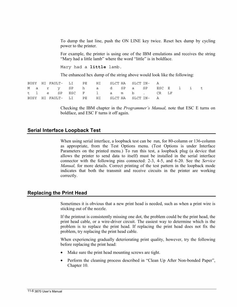
3870 User’s Manual11-6
To dump the last line, push the ON LINE key twice. Reset hex dump by cyclingpower to the printer.
For example, the printer is using one of the IBM emulations and receives the string“Mary had a little lamb” where the word “little” is in boldface.
Mary had a little lamb.
The enhanced hex dump of the string above would look like the following:
BUSY HI FAULT- LI PE HI SLCT HA SLCT IN- AM a r y SP h a d SP a SP ESC E l i tt l e SP ESC F l a m b . CR LFBUSY HI FAULT- LI PE HI SLCT HA SLCT IN- A
Checking the IBM chapter in the Programmer’s Manual, note that ESC E turns onboldface, and ESC F turns it off again.
Serial Interface Loopback Test
When using serial interface, a loopback test can be run, for 80-column or 136-columnas appropriate, from the Test Options menu. (Test Options is under InterfaceParameters on the printed menu.) To run this test, a loopback plug (a device thatallows the printer to send data to itself) must be installed in the serial interfaceconnector with the following pins connected: 2-3, 4-5, and 6-20. See the ServiceManual, for more details. Correct printing of the test pattern in the loopback modeindicates that both the transmit and receive circuits in the printer are workingcorrectly.
Replacing the Print Head
Sometimes it is obvious that a new print head is needed, such as when a print wire issticking out of the nozzle.
If the printout is consistently missing one dot, the problem could be the print head, theprint head cable, or a wire-driver circuit. The easiest way to determine which is theproblem is to replace the print head. If replacing the print head does not fix theproblem, try replacing the print head cable.
When experiencing gradually deteriorating print quality, however, try the followingbefore replacing the print head:
• Make sure the print head mounting screws are tight.
• Perform the cleaning process described in “Clean Up After Non-bonded Paper”,Chapter 10.
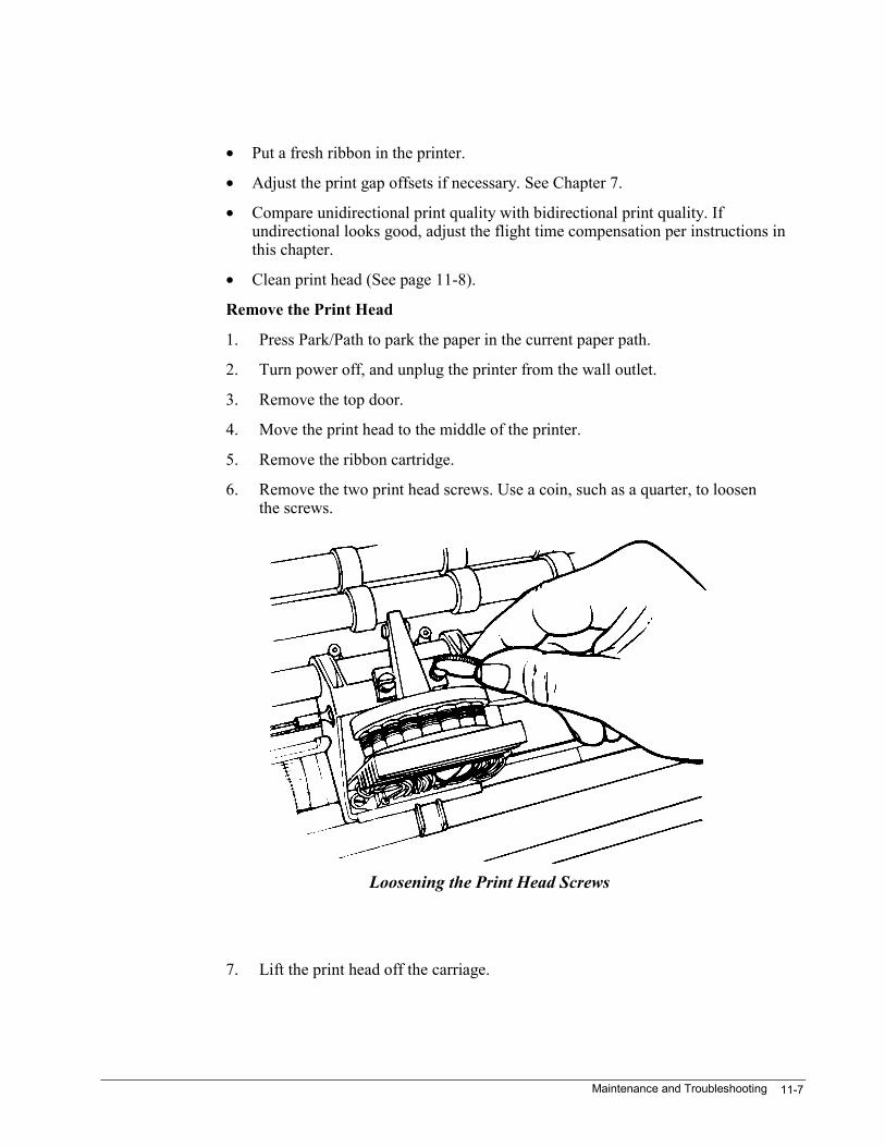
Maintenance and Troubleshooting 11-7
• Put a fresh ribbon in the printer.
• Adjust the print gap offsets if necessary. See Chapter 7.
• Compare unidirectional print quality with bidirectional print quality. Ifundirectional looks good, adjust the flight time compensation per instructions inthis chapter.
• Clean print head (See page 11-8).
Remove the Print Head
1. Press Park/Path to park the paper in the current paper path.
2. Turn power off, and unplug the printer from the wall outlet.
3. Remove the top door.
4. Move the print head to the middle of the printer.
5. Remove the ribbon cartridge.
6. Remove the two print head screws. Use a coin, such as a quarter, to loosenthe screws.
7. Lift the print head off the carriage.
Loosening the Print Head Screws
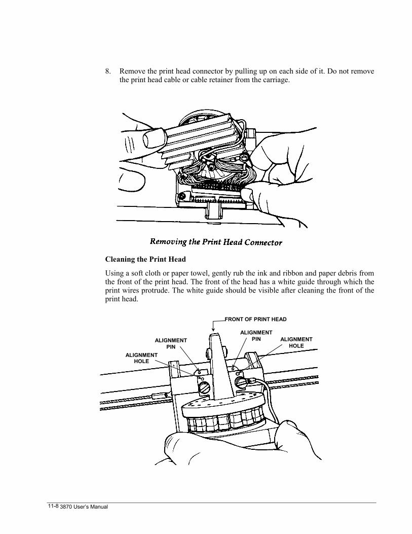
3870 User’s Manual11-8
8. Remove the print head connector by pulling up on each side of it. Do not removethe print head cable or cable retainer from the carriage.
Cleaning the Print Head
Using a soft cloth or paper towel, gently rub the ink and ribbon and paper debris fromthe front of the print head. The front of the head has a white guide through which theprint wires protrude. The white guide should be visible after cleaning the front of theprint head.
FRONT OF PRINT HEAD
ALIGNMENTPIN
ALIGNMENTHOLE
ALIGNMENTPIN ALIGNMENT
HOLE
Maintenance and Troubleshooting 11-9
Install the Print Head
1. Attach the print head connector to the connector in the carriage. Make sure it’sfirmly connected and that the wires are pressed down to avoid contact with theribbon cartridge.
2. Place the print head on the carriage.
3. Insert the two small alignment pin on the top of the carriage into the twoalignment holes on the bottom of the print head.
4. Make sure the black ground wire is under the right-hand screw.
5. Tighten the print head screws. Use a coin, such as a quarter, to tighten thesescrews.
6. Recheck the flight-time compensation; see next section.
Adjust the Flight-Time Compensation
Flight-time compensation affects the horizontal placement of dots during bidirectionalprinting. The traditional way to check it is to print full pages of nothing but uppercase“H” in bidirectional draft. If the vertical lines in the “H” wave back and forth fromone line of characters to the next, the adjustment is off.
Another way to tell if flight-time compensation is off is to compare unidirectionalletter-quality print with bidirectional letter-quality. If Unidirectional looks good butbidirectional looks like shadow printing, it’s an indication that this parameter needsadjusting.
• The printer has seen a lot of service.
• The print head is replaced.
• A carriage-mechanism component, such as a drive cable, is replaced.
• A software upgrade is installed.
CAUTION
The flight time test patterns are long lines ! Besure to use full-width (13.6-inch printing area)
paper for this procedure.
1. Make sure the print head gap is set correctly to avoid adjustment errors.
2. With the printer offline, press the Enter key to enter the LCD menu, then selectProg : PrMenu to enter the program mode and get a main menu printout.
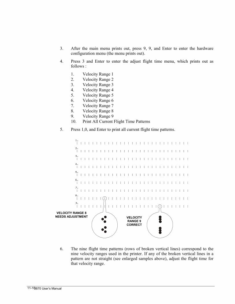
3870 User’s Manual11-10
3. After the main menu prints out, press 9, 9, and Enter to enter the hardwareconfiguration menu (the menu prints out).
4. Press 3 and Enter to enter the adjust flight time menu, which prints out asfollows :
1. Velocity Range 12. Velocity Range 23. Velocity Range 34. Velocity Range 45. Velocity Range 56. Velocity Range 67. Velocity Range 78. Velocity Range 89. Velocity Range 910. Print All Current Flight Time Patterns
5. Press 1,0, and Enter to print all current flight time patterns.
6. The nine flight time patterns (rows of broken vertical lines) correspond to thenine velocity ranges used in the printer. If any of the broken vertical lines in apattern are not straight (see enlarged samples above), adjust the flight time forthat velocity range.
VELOCITY RANGE 8NEEDS ADJUSTMENT VELOCITY
RANGE 9CORRECT
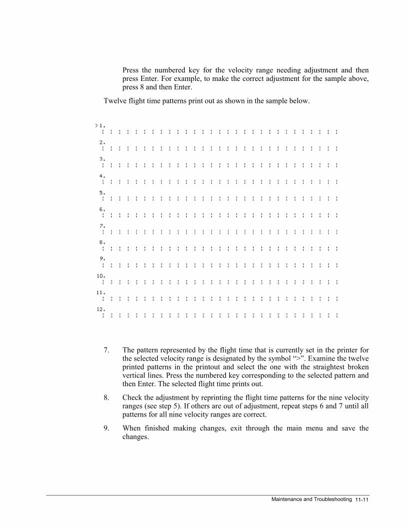
Maintenance and Troubleshooting 11-11
Press the numbered key for the velocity range needing adjustment and thenpress Enter. For example, to make the correct adjustment for the sample above,press 8 and then Enter.
Twelve flight time patterns print out as shown in the sample below.
7. The pattern represented by the flight time that is currently set in the printer forthe selected velocity range is designated by the symbol “>”. Examine the twelveprinted patterns in the printout and select the one with the straightest brokenvertical lines. Press the numbered key corresponding to the selected pattern andthen Enter. The selected flight time prints out.
8. Check the adjustment by reprinting the flight time patterns for the nine velocityranges (see step 5). If others are out of adjustment, repeat steps 6 and 7 until allpatterns for all nine velocity ranges are correct.
9. When finished making changes, exit through the main menu and save thechanges.
Interface 12-1
Chapter 12. InterfaceThe printer is equipped with both a serial and a parallel interface as standard features.This chapter provides information about both of these interfaces.
RS-232C Serial Interface
All signal levels conform to EIA RS-232C / CCITT V.24. The interface is extensivelyconfigurable from the printed menu. (See Chapter 4.) The printed status report showsthe current setting for the serial interface when it is active.
Serial parameters that can be controlled from the printed menu include:
• Baud rate
• Character bit definition
• Parity
• Ready-busy control using DC1 / DC3, CA, SCA, or CD
• Select-deselect using DC1 / DC3, CA, SCA, or CD
• Fault reporting using DC1 / DC3, CA, SCA, or CD
• CB (clear to send) or CC (data set ready) used to control transmission
• Lead polarity high or low for CD, CA, SCA, CB, and CC
• ETX (end of text) / ACK (acknowledge) protocol
• Receive buffer size – see Chapter 4.
3870 User’s Manual12-2
Parameters
In order for devices to communicate via RS-232, the character frames (baud rate,number of data bits, parity, number of stop bits), as well as the handshaking, must beset the same at the transmitter and receiver.
The factory default settings for the character frame are 9600 baud, 1 start bit, eightdata bits, one stop bit. The factory defaults for parity are ignore received parity andtransmit even parity.
The computer expects to receive the READY/ BUSY status (handshaking) and faultstatus from the printer by receiving a special character (busy by code), or by readingthe DC voltage on one or more of several signal wires (busy by level).
As shipped, the printer is set to indicate READY/ BUSY by code (XON/ XOFF) andalso by level (DTR and SRTS). A fault condition is reflected in XON/XOFF andDTR.
DOS Machines
For those using personal computers, the default handshaking is compatible, and thedefault character frame matches the DOS defaults. Always set DOS serial parametersexplicitly with the MODE command.
Seven or Eight Data Bits
A few years ago, a typical character-imaging device (CRT terminal or printer) wouldrender about 94 symbols. This reflects the limits of the teletype machine, which is aconceptual descendent of the typewriter. It only takes seven bits of data to selectamong 128 symbols or control codes.
When seven-bit data is used, the eighth bit in the byte is often used as a parity bit. Theparity bit might be set so that the number of ones in the byte is always even (evenparity) or always odd (odd parity). This serves as an error check. The parity bit canalso be set to always be zero (space) or always be one (mark).
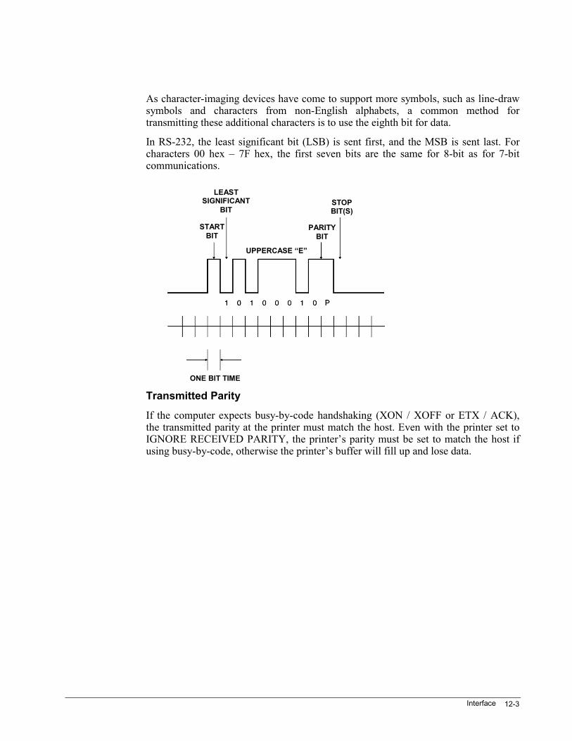
Interface 12-3
As character-imaging devices have come to support more symbols, such as line-drawsymbols and characters from non-English alphabets, a common method fortransmitting these additional characters is to use the eighth bit for data.
In RS-232, the least significant bit (LSB) is sent first, and the MSB is sent last. Forcharacters 00 hex – 7F hex, the first seven bits are the same for 8-bit as for 7-bitcommunications.
Transmitted Parity
If the computer expects busy-by-code handshaking (XON / XOFF or ETX / ACK),the transmitted parity at the printer must match the host. Even with the printer set toIGNORE RECEIVED PARITY, the printer’s parity must be set to match the host ifusing busy-by-code, otherwise the printer’s buffer will fill up and lose data.
STOPBIT(S)
PARITYBIT
LEASTSIGNIFICANT
BIT
STARTBIT
UPPERCASE “E”
ONE BIT TIME
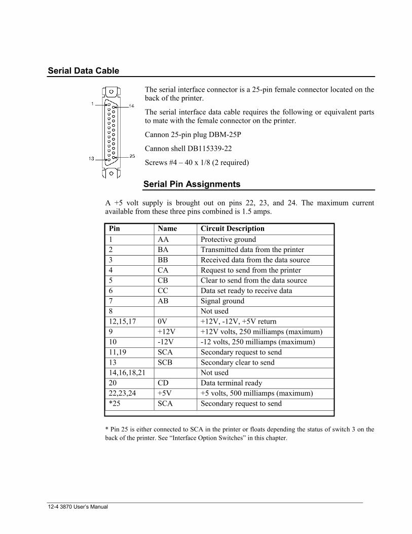
3870 User’s Manual12-4
Serial Data Cable
The serial interface connector is a 25-pin female connector located on theback of the printer.
The serial interface data cable requires the following or equivalent partsto mate with the female connector on the printer.
Cannon 25-pin plug DBM-25P
Cannon shell DB115339-22
Screws #4 – 40 x 1/8 (2 required)
Serial Pin Assignments
A +5 volt supply is brought out on pins 22, 23, and 24. The maximum currentavailable from these three pins combined is 1.5 amps.
Pin Name Circuit Description1 AA Protective ground2 BA Transmitted data from the printer3 BB Received data from the data source4 CA Request to send from the printer5 CB Clear to send from the data source6 CC Data set ready to receive data7 AB Signal ground8 Not used12,15,17 0V +12V, -12V, +5V return9 +12V +12V volts, 250 milliamps (maximum)10 -12V -12 volts, 250 milliamps (maximum)11,19 SCA Secondary request to send13 SCB Secondary clear to send14,16,18,21 Not used20 CD Data terminal ready22,23,24 +5V +5 volts, 500 milliamps (maximum)*25 SCA Secondary request to send
* Pin 25 is either connected to SCA in the printer or floats depending the status of switch 3 on theback of the printer. See “Interface Option Switches” in this chapter.
Interface 12-5
CENTRONICS Parallel Interface
With this interface, 7 – or 8-bit parallel data is accepted by the printer on a READY /BUSY closed loop basis at data transfer rates of up to 3.0 kilobytes per second. Whenthe printer is online with a parallel data source, data is strobed into the printer onecharacter at a time. A signal from the printer acknowledges receipt of each character.
Parallel interface configurations that may be selected from the menu are as follows:
• Busy indicated by busy lead and, optionally, by fault lead.
• Select / deselect (online / offline) indicated by the busy lead or the fault lead
• ACK pulsed during busy (not busy)
• ACK inhibited for offline to online transition
• ACK inhibited on recovery from paper-out condition.
• ACK inhibited on recovery from paper-out condition
• Lead polarity high or low for fault, select, paper out, ACK, busy, and strobe
• Prime on received DEL (delete) code
• Select/deselect by received DC1 / DC3 codes
Parallel Interface Signals
DATA STROBE: Input from the data source used to transfer data into the printerlogic. Minimum pulse duration is 0.4 microseconds. You can set STROBE polarityfrom the printed menu.
DATA BITS 1-8: Input character / control codes byte from the data source. High levelrepresents a binary 1 and low level a 0. Data setup time is not necessary and the strobepulse can be generated concurrently with data.
ACKNOWLEDGE: A pulse that is generated by the printer to indicate receipt of acharacter. Menu options allow you to selectively enable or disable the pulse onrecovery from any fault, paper-out, or deselect state; to set the pulse polarity; and toset the position of the pulse relative to busy.
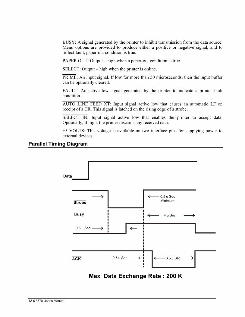
3870 User’s Manual12-6
BUSY: A signal generated by the printer to inhibit transmission from the data source.Menu options are provided to produce either a positive or negative signal, and toreflect fault, paper-out condition is true.
PAPER OUT: Output – high when a paper-out condition is true.
SELECT: Output – high when the printer is online.
PRIME: An input signal. If low for more than 50 microseconds, then the input buffercan be optionally cleared.
FAULT: An active low signal generated by the printer to indicate a printer faultcondition.
AUTO LINE FEED XT: Input signal active low that causes an automatic LF onreceipt of a CR. This signal is latched on the rising edge of a strobe.
SELECT IN: Input signal active low that enables the printer to accept data.Optionally, if high, the printer discards any received data.
+5 VOLTS: This voltage is available on two interface pins for supplying power toexternal devices.
Parallel Timing Diagram
4 u Sec
3.5 u Sec0.5 u Sec
0.5 u Sec
0.5 u SecMinimum
Data
Strobe
Max Data Exchange Rate : 200 K
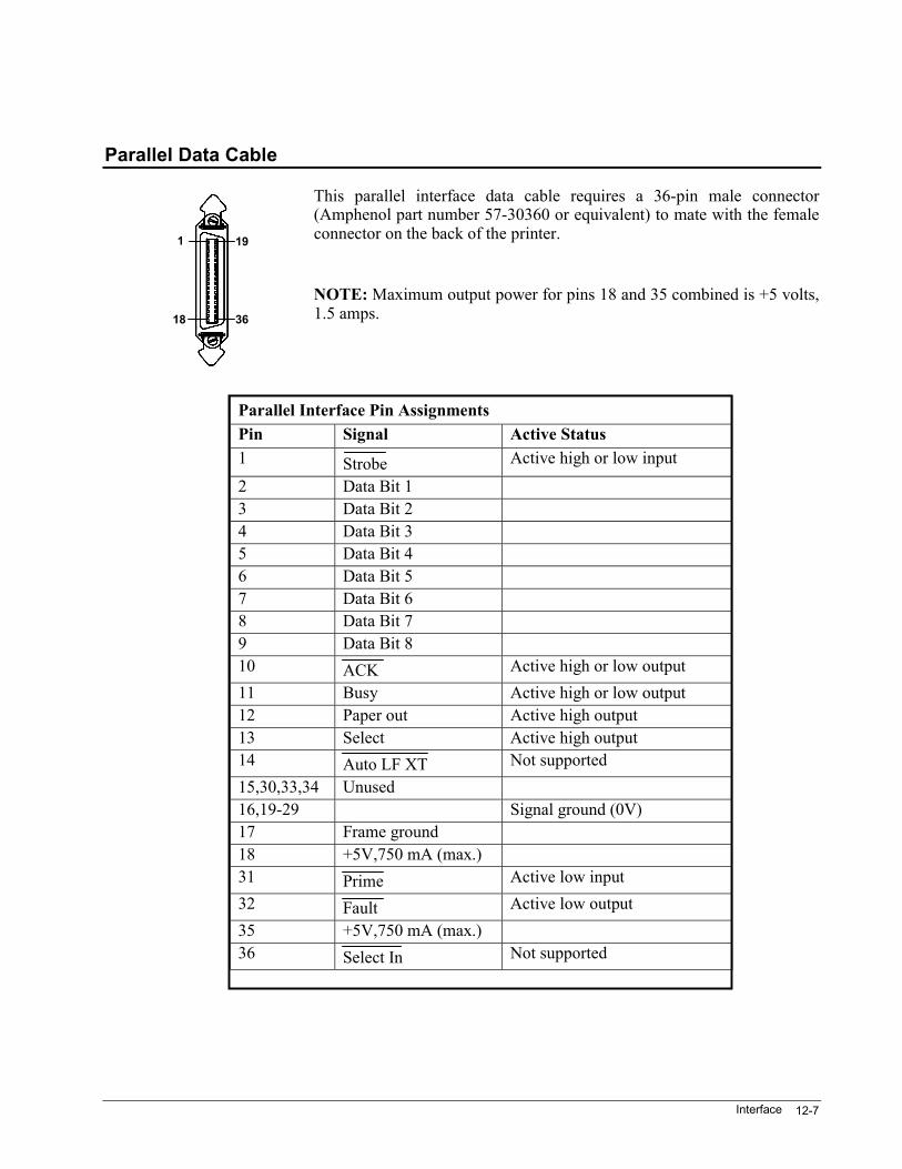
Interface 12-7
Parallel Data Cable
This parallel interface data cable requires a 36-pin male connector(Amphenol part number 57-30360 or equivalent) to mate with the femaleconnector on the back of the printer.
NOTE: Maximum output power for pins 18 and 35 combined is +5 volts,1.5 amps.
Parallel Interface Pin AssignmentsPin Signal Active Status1 Strobe Active high or low input
2 Data Bit 13 Data Bit 24 Data Bit 35 Data Bit 46 Data Bit 57 Data Bit 68 Data Bit 79 Data Bit 810 ACK Active high or low output11 Busy Active high or low output12 Paper out Active high output13 Select Active high output14 Auto LF XT Not supported15,30,33,34 Unused16,19-29 Signal ground (0V)17 Frame ground18 +5V,750 mA (max.)31 Prime Active low input32 Fault Active low output35 +5V,750 mA (max.)36 Select In Not supported
191
3618
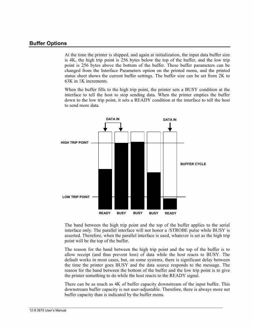
3870 User’s Manual12-8
Buffer Options
At the time the printer is shipped, and again at initialization, the input data buffer sizeis 4K, the high trip point is 256 bytes below the top of the buffer, and the low trippoint is 256 bytes above the bottom of the buffer. These buffer parameters can bechanged from the Interface Parameters option on the printed menu, and the printedstatus sheet shows the current buffer settings. The buffer size can be set from 2K to63K in 1K increments.
When the buffer fills to the high trip point, the printer sets a BUSY condition at theinterface to tell the host to stop sending data. When the printer empties the bufferdown to the low trip point, it sets a READY condition at the interface to tell the hostto send more data.
The band between the high trip point and the top of the buffer applies to the serialinterface only. The parallel interface will not honor a /STROBE pulse while BUSY isasserted. Therefore, when the parallel interface is used, whatever is set as the high trippoint will be the top of the buffer.
The reason for the band between the high trip point and the top of the buffer is toallow receipt (and thus prevent loss) of data while the host reacts to BUSY. Thedefault works in most cases, but, on some systems, there is significant delay betweenthe time the printer goes BUSY and the data source responds to the message. Thereason for the band between the bottom of the buffer and the low trip point is to givethe printer something to do while the host reacts to the READY signal.
There can be as much as 4K of buffer capacity downstream of the input buffer. Thisdownstream buffer capacity is not user-adjustable. Therefore, there is always more netbuffer capacity than is indicated by the buffer menu.
DATA IN DATA IN
BUFFER CYCLE
HIGH TRIP POINT
LOW TRIP POINT
READY BUSY BUSYBUSY READY

Emulation and Software Options A-1
Appendix A. Emulation and Software OptionsThe emulation and software options are straps that control less frequently adjustedaspects of the printer configuration. They are controlled from the printed menu.Unlike other menu items, the menu does not print a description of each option. Thischapter tells what the options do and how to set them.
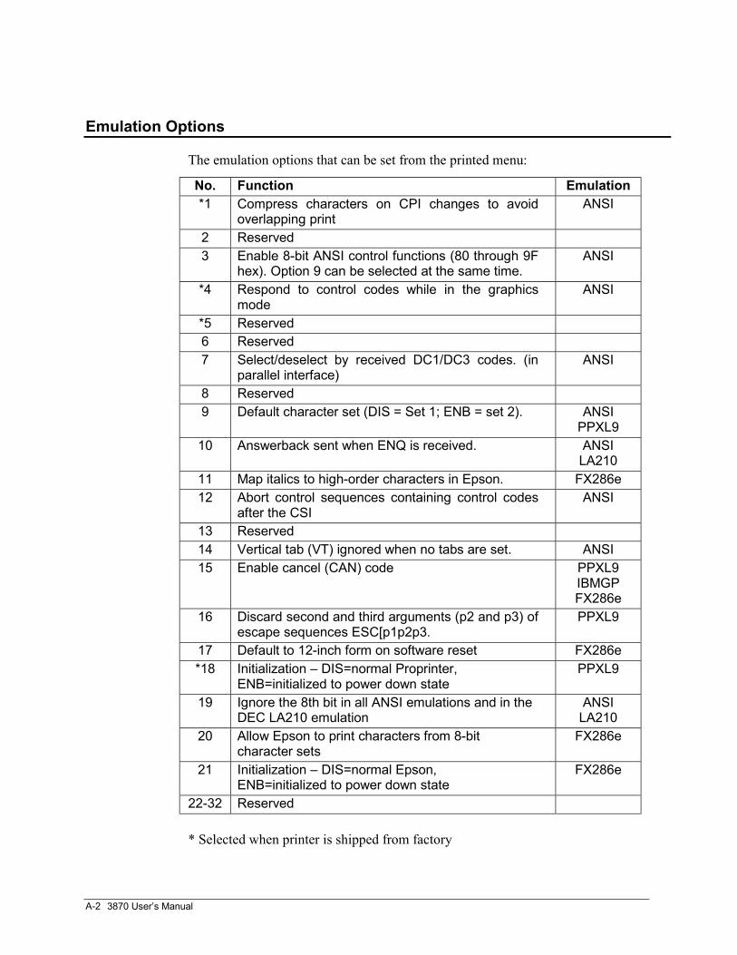
3870 User’s ManualA-2
Emulation Options
The emulation options that can be set from the printed menu:
No. Function Emulation*1 Compress characters on CPI changes to avoid
overlapping printANSI
2 Reserved3 Enable 8-bit ANSI control functions (80 through 9F
hex). Option 9 can be selected at the same time.ANSI
*4 Respond to control codes while in the graphicsmode
ANSI
*5 Reserved6 Reserved7 Select/deselect by received DC1/DC3 codes. (in
parallel interface)ANSI
8 Reserved9 Default character set (DIS = Set 1; ENB = set 2). ANSI
PPXL910 Answerback sent when ENQ is received. ANSI
LA21011 Map italics to high-order characters in Epson. FX286e12 Abort control sequences containing control codes
after the CSIANSI
13 Reserved14 Vertical tab (VT) ignored when no tabs are set. ANSI15 Enable cancel (CAN) code PPXL9
IBMGPFX286e
16 Discard second and third arguments (p2 and p3) ofescape sequences ESC[p1p2p3.
PPXL9
17 Default to 12-inch form on software reset FX286e*18 Initialization – DIS=normal Proprinter,
ENB=initialized to power down statePPXL9
19 Ignore the 8th bit in all ANSI emulations and in theDEC LA210 emulation
ANSILA210
20 Allow Epson to print characters from 8-bitcharacter sets
FX286e
21 Initialization – DIS=normal Epson,ENB=initialized to power down state
FX286e
22-32 Reserved
* Selected when printer is shipped from factory
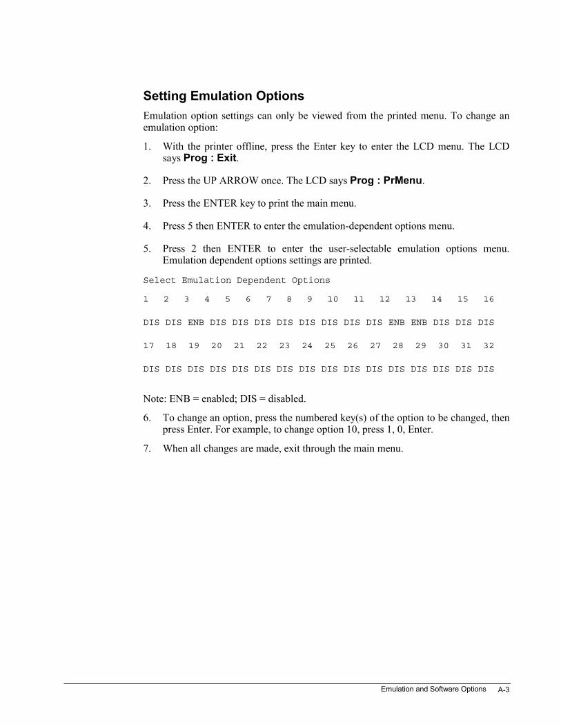
Emulation and Software Options A-3
Setting Emulation OptionsEmulation option settings can only be viewed from the printed menu. To change anemulation option:
1. With the printer offline, press the Enter key to enter the LCD menu. The LCDsays Prog : Exit.
2. Press the UP ARROW once. The LCD says Prog : PrMenu.
3. Press the ENTER key to print the main menu.
4. Press 5 then ENTER to enter the emulation-dependent options menu.
5. Press 2 then ENTER to enter the user-selectable emulation options menu.Emulation dependent options settings are printed.
Select Emulation Dependent Options
1 2 3 4 5 6 7 8 9 10 11 12 13 14 15 16
DIS DIS ENB DIS DIS DIS DIS DIS DIS DIS DIS ENB ENB DIS DIS DIS
17 18 19 20 21 22 23 24 25 26 27 28 29 30 31 32
DIS DIS DIS DIS DIS DIS DIS DIS DIS DIS DIS DIS DIS DIS DIS DIS
Note: ENB = enabled; DIS = disabled.
6. To change an option, press the numbered key(s) of the option to be changed, thenpress Enter. For example, to change option 10, press 1, 0, Enter.
7. When all changes are made, exit through the main menu.
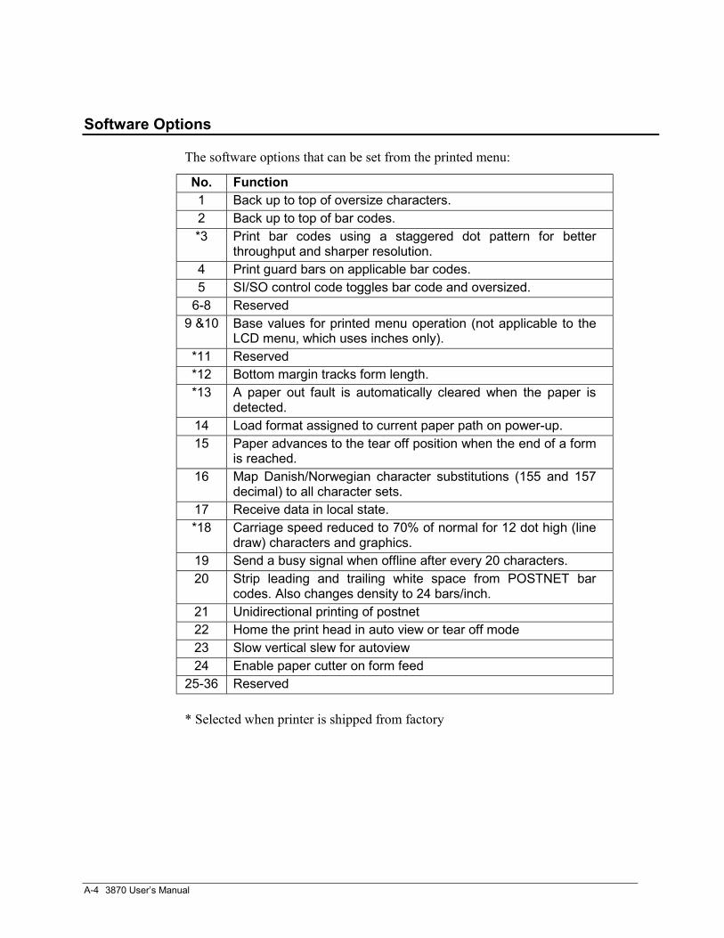
3870 User’s ManualA-4
Software Options
The software options that can be set from the printed menu:
No. Function1 Back up to top of oversize characters.2 Back up to top of bar codes.*3 Print bar codes using a staggered dot pattern for better
throughput and sharper resolution.4 Print guard bars on applicable bar codes.5 SI/SO control code toggles bar code and oversized.
6-8 Reserved9 &10 Base values for printed menu operation (not applicable to the
LCD menu, which uses inches only).*11 Reserved*12 Bottom margin tracks form length.*13 A paper out fault is automatically cleared when the paper is
detected.14 Load format assigned to current paper path on power-up.15 Paper advances to the tear off position when the end of a form
is reached.16 Map Danish/Norwegian character substitutions (155 and 157
decimal) to all character sets.17 Receive data in local state.*18 Carriage speed reduced to 70% of normal for 12 dot high (line
draw) characters and graphics.19 Send a busy signal when offline after every 20 characters.20 Strip leading and trailing white space from POSTNET bar
codes. Also changes density to 24 bars/inch.21 Unidirectional printing of postnet22 Home the print head in auto view or tear off mode23 Slow vertical slew for autoview24 Enable paper cutter on form feed
25-36 Reserved
* Selected when printer is shipped from factory
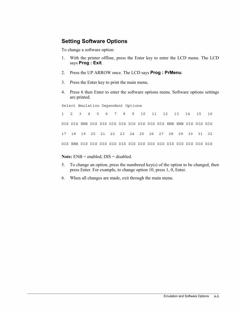
Emulation and Software Options A-5
Setting Software OptionsTo change a software option:
1. With the printer offline, press the Enter key to enter the LCD menu. The LCDsays Prog : Exit.
2. Press the UP ARROW once. The LCD says Prog : PrMenu.
3. Press the Enter key to print the main menu.
4. Press 6 then Enter to enter the software options menu. Software options settingsare printed.
Select Emulation Dependent Options
1 2 3 4 5 6 7 8 9 10 11 12 13 14 15 16
DIS DIS ENB DIS DIS DIS DIS DIS DIS DIS DIS ENB ENB DIS DIS DIS
17 18 19 20 21 22 23 24 25 26 27 28 29 30 31 32
DIS ENB DIS DIS DIS DIS DIS DIS DIS DIS DIS DIS DIS DIS DIS DIS
Note: ENB = enabled; DIS = disabled.
5. To change an option, press the numbered key(s) of the option to be changed, thenpress Enter. For example, to change option 10, press 1, 0, Enter.
6. When all changes are made, exit through the main menu.
Hardware Configuration Menu B-1
Appendix B. Hardware Configuration MenuThe Hardware Configuration menu is a hidden submenu (item 99) on the main printedmenu. Use it to:
Change hardware options
Adjust the print wire flight time
To change a hardware option:
1. With the printer offline, press the Enter key to enter the LCD menu. The LCDsays Prog : Exit.
2. Press the UP ARROW once. The LCD says Prog : PrMenu.
3. Press the ENTER key to print the main menu.
4. Press 9, 9, and ENTER to print the hardware options menu.
5. Press 2 then ENTER to enter the hardware options menu.
6. To select or deselect an option, press the numbered key(s) for the number of theoption to be changed and press menu.
7. When all changes are made, exit through the main menu.
Adjust the print wire flight time.
Directions for adjusting the flight-time compensation of the print wires are found in“Adjust the Flight-Time Compensation” in Chapter 11.
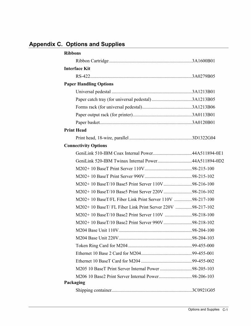
Options and Supplies C-1
Appendix C. Options and SuppliesRibbons
Ribbon Cartridge ......................................................................3A1600B01Interface Kit
RS-422......................................................................................3A0279B05Paper Handling Options
Universal pedestal ....................................................................3A1213B01Paper catch tray (for universal pedestal) ..................................3A1213B05Forms rack (for universal pedestal)..........................................3A1213B06Paper output rack (for printer)..................................................3A0113B01Paper basket..............................................................................3A0120B01
Print HeadPrint head, 18-wire, parallel .....................................................3D1322G04
Connectivity OptionsGeniLink 510-IBM Coax Internal Power.................................44A511894-0E1GeniLink 520-IBM Twinax Internal Power.............................44A511894-0D2M202+ 10 BaseT Print Server 110V........................................98-215-100M202+ 10 BaseT Print Server 990V........................................98-215-102M202+ 10 BaseT/10 Base5 Print Server 110V........................98-216-100M202+ 10 BaseT/10 Base5 Print Server 220V........................98-216-102M202+ 10 BaseT/FL Fiber Link Print Server 110V ...............98-217-100M202+ 10 BaseT/ FL Fiber Link Print Server 220V ..............98-217-102M202+ 10 BaseT/10 Base2 Print Server 110V .......................98-218-100M202+ 10 BaseT/10 Base2 Print Server 990V........................98-218-102M204 Base Unit 110V..............................................................98-204-100M204 Base Unit 220V..............................................................98-204-103Token Ring Card for M204......................................................99-455-000Ethernet 10 Base 2 Card for M204...........................................99-455-001Ethernet 10 BaseT Card for M204 ...........................................99-455-002M205 10 BaseT Print Server Internal Power ...........................98-205-103M206 10 Base2 Print Server Internal Power............................98-206-103
PackagingShipping container....................................................................3C0921G05
D-1
Appendix D. Specifications
Performance
Maximum Printing Speed Models - 3870
• 900 cps data processing (12 CPI)
• 750 cps data processing (10 CPI)
• 240 cps letter quality (12 CPI)
• 200 cps letter quality (10 CPI)
Serial Data Buffer 63K selectable in 1K increments
Physical
Width: 26.9 in. (683mm)
Height: 12.1 in. (307 mm)
Depth: 13.9 in. (353 mm)
Weight: 52 lb (23.4 kg) Note: Printer is UPS shippable
Electrical
Voltage: 115 or 230 VAC ± 15%
Frequency: 50 or 60 Hz ± 2 Hz
Power Consumption: Standby: 35 wattsPrinting: 130 watts 1A.
Data Transmission
Code: US ASCII/ISO 7-or 8-bit
Interface: Dual RS-232C serial and CENTRONICS parallel
Speed (serial interface): 110, 300, 600, 1200, 2400, 4800, 9600 and 19200 baud
Speed (parallel interface): 30 Kbytes
Data connectors: 25-pin type DB female and 36-pin Amphenol
3870 User’s ManualD-2
Paper Handling
Paper Paths: Rear, front/bottom, and manual. Any four of the stored user-definedformats, including page and print settings can be assigned to any of the three paperpaths.
Zero Tear-off Feature: Adjustable for distance
Paper Loading and Parking: Automatic
Top of Form Setting: Automatic
Paper Drive: 6-pin push tractors in front/bottom and rear, friction feed top (manual)feed.
Paper Width:
Continuous forms 3 – 16 in.Single cut sheets 3.5 – 17 in. wide X 5 – 17 in. longwith a minimum width to length ratio of 0.45 in.
Maximum Number of Copies: Original plus eight in front path, original plus five inrear path.
Maximum Forms Set Thickness: 0.025 in.
Paper Slew: 15 in./sec. default, 5 in./sec. user selectable
Paper Positioning: Horizontal any position; vertical within 1/72 in.
Printer Emulations
• ANSI X 3.64
• IBM GP
• IBM Proprinter XL III
• Epson FX286e
• DEC LA210
• Genicom 3410X
D-3
Print Technology
Type: Matrix impact
Print Head: 18-wire parallel (two 9-wire arrays)
Direction of Printing: Logic-seeking bi-directional or unidirectional(operator-selectable)
Print Modes: Proportional, compressed, shadow, double strike, underline, expanded,superscripts, and subscripts.
Character Sets: IBM Set I, II and All-Character sets plus 30 international charactersets.
Head Slew: 75 in./sec. maximum LF Interval: 35 msec at 6 LPI
Character Spacing: 10, 12, 13.1, 15, 16.7, 17.1, 20 CPI plus program-selectable
Line Spacing: 3, 4, 6, 8 LPI plus n/144 in.
Print Line:
with no paper shear – 13.6 inchespaper shear – 12.7 inches
Print Styles:
Standard:
Gothic, Courier, Wide Gothic, Gothic Italic, Courier Italic, Micro Gothic,OCR-A, OCR-B, Oversize.
Barcode styles:
Interleaved 2 of 5, Bi-directional 2 of 5, Matrix 2 of 5, Industrial 2 of 5, Code 3of 9, EAN-2, EAN-5, EAN-8, EAN-13, Code 11, Code BCD, Codabar a/t, Codabarb/n, Codabar c/*, Codabar d/e, UPC-A, UPC-E, UPC-2, UPC-5, Code 93, Code 128(A-B-C), MSI, POSTNET
Dot Graphics Resolution:
Horizontal 60 to 400 dpi (protocol dependent)
Vertical 72 or 144 dpi (protocol dependent)
Ribbon Cartridge: Type of material is nylon; ribbon life is 15 million characters atdata processing (draft) resolution.
3870 User’s ManualD-4
Form Control
Margins:
Left and right: any position
Top and bottom: any position
Horizontal Tabs: 22, 28, or 32 absolute or relative (emulation dependent)
Vertical Tabs: 12, 16, or 64 absolute or relative (emulation dependent)
Maximum Form Length: 22 in.
IIndex-1
Complete Index
>
> Arrow ..............................................................................4-1
A
Access the Printed Menu ....................................................4-2Active Format .....................................................................6-2Adjust Top-of-Form.......................................................... 2-17Auto Head Gap Adjust........................................................7-2Auto Load....................................................................... 10-11auto switching interface .................................................... 2-18
B
Bottom Feed ..................................................................... 10-6Buffer Options .................................................................. 12-8
C
CENTRONICS Parallel Interface ..................................... 12-5Change a Format - Printed Menu........................................6-3Change Ribbon ...................................................................7-2Clean the Printer ............................................................... 11-1Continuous Envelopes .................................................... 10-15Continuous Forms........................................................... 10-16control panel keys ...............................................................3-1Control Panel Lockouts ......................................................5-1Currently Assigned Format.................................................6-5
D
DOS Machines.................................................................. 12-2
E
Emulation Options......................................................A-1,A-2Exit the Printed Menu....................................................... 4-12
F
Flight-Time Compensation ............................................... 11-9Formats ...............................................................................6-1Front Feed......................................................................... 10-6Front Tractors ................................................................... 10-4
H
Hardware Configuration Menu.......................................... B-1Hex Dump ........................................................................ 11-5
I
Install the Print Head ........................................................ 11-9Install the Ribbon ............................................................... 2-5Interface............................................................................ 12-1ISU ..............................................................................9-1, 9-2
L
LCD Head Gap Menu......................................................... 7-1LCD menu .......................................................................... 3-3LCD Menu Map ................................................................. 3-5LCD Message Display........................................................ 6-5Left Margin......................................................................... 8-5Left Print Reference.....................................................8-3, 8-5Line Registration on the first form.................................... 2-20Linking Emulations to Formats .......................................... 6-6Load a Form ..................................................................... 2-14Load Length Adjustment .................................................... 8-5Local Margins..................................................................... 8-4Lock the Printed Menu ....................................................... 5-3Lock the Printer Online ...................................................... 5-1
M
Maintenance ..................................................................... 11-1Manual Paper Path.......................................................... 10-12Manual Path.................................................................... 10-14Margins for Menu Listings ................................................. 4-3Multipart Forms.............................................................. 10-11
N
Nonbonded Paper ........................................................... 10-15
O
Options and Supplies ......................................................... C-1
3870 User’s ManualIndex-2
P
Paper Handling ................................................................. 10-1Paper Out........................................................................ 10-11Paper Path Change..............................................................6-3Paper Paths ............................................................10-9, 10-10Paper Tension ................................................................... 10-2Parallel Data Cable ........................................................... 12-7Parallel Interface Signals .................................................. 12-5Parallel Timing Diagram .................................................. 12-6Parameters ........................................................................ 12-2pedestal ...............................................................................2-1power cord ..........................................................................2-1Power Cords .......................................................................2-3power switch.......................................................................2-4Power Up............................................................................9-1Power-up ............................................................................9-1Print a Test Pattern ........................................................... 2-15Print All Format Information..............................................6-2Print Head......................................................................... 11-6Print Head Gap Adjustment.............................................. 2-17print nozzle ....................................................................... 2-10Print Reference ...................................................................8-2printed menu.......................................................................3-3Printed Menu ......................................................................4-1Printed Menu Map..............................................................4-3Printer Specifications......................................................... D-1printer stand ........................................................................2-1Put Paper in the Tractors................................................... 2-11
R
Rear Tractors .................................................................... 10-7Remote Path Change Failure .......................................... 10-10Remove the Print Head..................................................... 11-7Removing the Ribbon....................................................... 2-10Rename a Format................................................................6-5Replacing the Print Head .................................................. 11-6Reset ...................................................................................9-1ribbon advance knob...........................................................2-9ribbon cartridge...................................................................2-1ribbon drive spindle..........................................................2-8ribbon guide...................................................................... 2-10
rolling-ASCII pattern........................................................ 2-15RS-232C Serial Interface .................................................. 12-1
S
Save a Format from the Control Panel................................ 6-4Save a Format from the Host .............................................. 6-4Saving to a Format.............................................................. 7-4Select a Format from the Control Panel.............................. 6-4Select a Format from the Host ............................................ 6-4Select the Assigned Format from the Host ......................... 6-5Select the Emulation........................................................... 3-7Semiautomatic Head Gap Adjust........................................ 7-5Serial Data Cable .............................................................. 12-4Serial Interface Loopback Test ......................................... 11-6Serial Pin Assignments ..................................................... 12-4serial printer cables........................................................... 2-18Setting Emulation Options................................................. A-3Setting Software Options................................................... A-5Setting to a Format ............................................................. 7-4Seven or Eight Data Bits .................................................. 12-2Software Options ............................................................... 1, 4Software Upgrade ............................................................... 9-2Status Sheet ........................................................................ 3-9Stored Formats.................................................................... 6-2
T
Tear Off Distance ............................................................... 8-3Top Margin......................................................................... 8-4Top Print Reference.....................................................8-2, 8-4tractor assembly.................................................................. 2-1tractors .............................................................................. 2-11Transmitted Parity ............................................................ 12-3Troubleshooting.......................................................11-1, 11-3
V
Various Keys ...................................................................... 5-3Vertical Paper Movement ................................................... 8-1Voltage Selector Switch ..................................................... 2-2