Gefran SIEI AVyL Manual
225
...... Instruction Manual ARTDriveL Lift Vector AC Drives ARTDriveL AVy...-...-AC AVy...-...-AC4 AVy...-...-BR AVy...-...-BR4
Transcript of Gefran SIEI AVyL Manual

...... Instruction Manual
AR
TDriv
eLLift Vector AC Drives
ARTDriveLAVy...-...-AC
AVy...-...-AC4
AVy...-...-BR
AVy...-...-BR4

Thank you for choosing this Gefran-Siei product.We will be glad to receive any possible information which could help usimproving this manual. The e-mail address is the following: [email protected] using the product, read the safety instruction section carefully.Keep the manual in a safe place and available to engineering and installationpersonnel during the product functioning period.The manufacturer has the right to modify products, data and dimensions withoutnotice.The data can only be used for the product description and they can not beunderstood as legally stated properties.All rights reserved
This manual is updated according to software version 3.5XX and RV33-4regulation card.The identification number of the software version can be read on the inverternameplate or on the label on the FLASH memories mounted on the regulationcard.

ARTDriveL Instruction Manual Table of Contents • 3
Table of Contents
Safety Symbol Legend - Precautions de securité ............................................................ 6Chapter 0 - Safety Precautions ........................................................................................ 7Chapter 1 - Functions and General Features ................................................................. 13
1.1 Drive ......................................................................................................................................... 131.2 Motors ..................................................................................................................................... 15
Chapter 2 - Inspection procedures, Components Identification and Standard Specifications .... 172.1 Upon Delivery Inspection Procedures ...................................................................................... 17
2.1.1 General ................................................................................................................................................... 172.1.2 Inverter type designation ....................................................................................................................... 172.1.3 Nameplate .............................................................................................................................................. 18
Figure 2.1.3.1: Identification nameplate .................................................................................................... 18Figure 2.1.3.2: Firmware & Card revision level nameplate ........................................................................ 18Figure 2.1.3.3: Nameplates position .......................................................................................................... 18
2.2 Component Identification ......................................................................................................... 19Figure 2.2.1: Basic Setup of Frequency Inverter ....................................................................................... 19
2.3 Standard Specifications ........................................................................................................... 202.3.1 Permissible Environmental Conditions ................................................................................................... 20Disposal of the Device ..................................................................................................................................... 212.3.2 AC Input/Output Connection .................................................................................................................. 212.3.3 AC Input ................................................................................................................................................. 212.3.4 AC Output ............................................................................................................................................... 21
Figure 2.3.4.1: Rating of Drive in Function of Switching Frequency .......................................................... 22Table 2.3.4.1: AC Input/Output Specifications ........................................................................................... 23Table 2.3.4.2-A: Overload Capability (Sizes 1007 ... 4370) ....................................................................... 24Table 2.3.4.2-B: Overload Capability (Sizes 5450... 81600) ...................................................................... 25
2.3.6 Accuracy ................................................................................................................................................ 26Table 2.3.6.1: Maximum / Minimum Output Frequency ............................................................................. 26
2.3.5 I/O and Encoder Specifications .............................................................................................................. 26Table 2.3.6.4: Torque Specifications .......................................................................................................... 27Table 2.3.6.2: Speed Reference / Feedback Resolution and Maximum Limits ........................................... 27Table 2.3.6.3: Speed Regulator Bandwidth ............................................................................................... 27
Chapter 3 - Mechanical Installation Guidelines ............................................................. 283.1 Dimensions and Mounting Methods ........................................................................................ 28
Figure 3.1.1: Drive Dimensions (Sizes 1007 ... 3150) ................................................................................ 28Figure 3.1.2: Mounting Methods (Sizes 1007 ... 3150) ............................................................................ 28Table 3.1.1: Drive Dimensions and Weights (Sizes 1007 ... 3150) .......................................................... 29Figure 3.1.3: Drive Dimensions (Sizes 4220 ... 81600) .............................................................................. 29Figure 3.1.4: Mounting Methods (Sizes 4220 ... 81600) ........................................................................... 30Table 3.1.2: Drive Dimensions and Weights (Sizes 4220 ... 81600) ......................................................... 30Figure 3.1.5: Keypad Positioning ............................................................................................................... 30
3.2 Watts Loss, Heat Dissipation, Internal Fans and Minimum Cabinet Opening Suggested for theCooling ................................................................................................................................... 31Table 3.2.1: Heat Dissipation and Required Air Flow ................................................................................. 31Table 3.2.2: Minimum Cabinet Opening Suggested for the Cooling ........................................................... 31
3.2.1 Cooling Fans Power Supply .................................................................................................................... 32Figure 3.2.1: UL Type Fans Connections on AVy7900, AVy71100 and AVy71320 Sizes ............................ 32Figure 3.2.2: UL Type Fans Connections on AVy6750 and AVy81600 Sizes .............................................. 32Figure 3.2.3: Example for External Connection .......................................................................................... 33
4 • Table of Contents ARTDriveL Instruction Manual
3.3 Installation Mounting Clearance .............................................................................................. 34Figure 3.3.1: Max. Angle of Inclination ..................................................................................................... 34Figure 3.3.2: Mounting Clearance ............................................................................................................. 34
Chapter 4 - Wiring Procedure ........................................................................................ 354.1 Accessing the Connectors ....................................................................................................... 35
4.1.1 Removing the Covers ............................................................................................................................. 35Figure 4.1.1: Removing the Covers (Sizes 1007 to 3150) .......................................................................... 35Figure 4.1.2: Removing the Covers (Sizes 4185 to 81600) ........................................................................ 36
4.2 Power Section .......................................................................................................................... 364.2.1 Terminal Assignment on Power Section / Cable Cross-Section ............................................................. 37
Table 4.2.1.1: Power Section Terminals from 1007 to 3150 ...................................................................... 37Table 4.2.1.2: Power Section Terminals from 4185 to 81600 .................................................................... 37Table 4.2.1.3: Maximum Cable Cross Section for Power Terminals ......................................................... 38Table 4.2.1.4: Maximum Permissible Cable Cross-section on the Plug-in Terminals of the Regulator Section39Table 4.2.1.5: Maximum Control Cable Lengths ........................................................................................ 39
4.3 Regulation Section ................................................................................................................... 404.3.1 RV33-4 Regulation Card Switch & Jumpers ........................................................................................... 40
Table 4.3.1.1: LEDs & Test points on Regulation Card ............................................................................... 40Table 4.3.1.2: Jumpers and dip-switches on Regulation Card RV33 ......................................................... 41
4.3.2 Terminal Assignments on Regulation Section ........................................................................................ 42Table 4.3.2.1: Plug-in Terminal Strip Assignments .................................................................................... 42
4.4 Potentials of the Control Section .............................................................................................. 43Figure 4.4.1-A: Potentials of the control section, Digital I/O NPN connection ........................................... 43Figure 4.4.1-B: Potentials of the control section, Digital I/O PNP connection ........................................... 44
4.5 Encoders ................................................................................................................................................... 45Table 4.5.1: Recommended Cable Section and Length for the Connection of Encoders ............................ 46Table 4.5.2: Encoders Setting via S11...S23 Jumpers ............................................................................... 46Table 4.5.3: Encoders Connections ........................................................................................................... 46Table 4.5.4: Assignment of the High Density XE Connector for a Sinusoidal or a Digital Encoder ............. 49
4.5.1 XFR Connector Assignments (on optional EXP-RES Expansion Board for Resolver) .............................. 494.5.2 Encoder Simulation ............................................................................................................................. 50
4.6 Connection Diagrams ............................................................................................................... 51Figure 4.6.1: Standard Connection Diagram .............................................................................................. 51
4.6.1 Expansion Card Connection ................................................................................................................... 52Figure 4.6.2: Common Output Contactors Management ........................................................................... 52Figure 4.6.3: Separate Output Contactors Management ........................................................................... 53
4.7 Circuit Protection ..................................................................................................................... 544.7.1 External Fuses for the Power Section .................................................................................................... 54
Table 4.7.1.1: External Fuse Types for AC Input Side ................................................................................. 544.7.2 External Fuses for the Power Section DC Input Side ............................................................................. 55
Table 4.7.2.1: External Fuses Type for DC Input Side ................................................................................ 554.7.3 Internal Fuses ......................................................................................................................................... 55
Table 4.7.3.1: Internal Fuses ..................................................................................................................... 554.8 Chokes / Filters ........................................................................................................................ 56
4.8.1 AC Input Chokes ..................................................................................................................................... 56Table 4.8.1.1: 3-Phase AC Input Chokes .................................................................................................. 56
4.8.2 Output Chokes ........................................................................................................................................ 56Table 4.8.2.1: Recommended Output Chokes ............................................................................................ 57
4.8.3 Interference Suppression Filters ............................................................................................................. 574.9. Braking Units .......................................................................................................................... 58
Figure 4.9.1: Operation with Braking Unit (Principle) ................................................................................ 584.9.1 Internal Braking Unit ............................................................................................................................... 58

ARTDriveL Instruction Manual Table of Contents • 5
Figure 4.9.1.1: Connection with Internal Braking Unit and External Braking Resistor ............................... 584.9.2 External Braking Resistor ....................................................................................................................... 59
Table 4.9.2.1: Lists and Technical Data of the External Standard Resistors .............................................. 59Figure 4.9.2.2: Limit Operating Braking Cycle with Typical Triangular Power Profile ................................. 59Figure 4.9.2.3: Braking Cycle with TBR / TC = 20% ................................................................................. 60Figure 4.9.2.4: Generic Braking Cycle with Triangular Profile ................................................................... 61Table 4.9.2.2: Braking Thresholds for Different Mains .............................................................................. 62Table 4.9.2.3: Technical Data of the Internal Braking Units ....................................................................... 62
4.10 Buffering the Regulator Supply .............................................................................................. 63Table 4.10.1: DC Link Buffer Time ............................................................................................................ 63Figure 4.10.1: Buffering the Regulator Supply by Means of Additional Intermediate Circuit Capacitors ... 64
4.11 Discharge Time of the DC-Link ............................................................................................... 65Table 4.11.1: DC Link Discharge Time ...................................................................................................... 65
Chapter 5 - Serial Interface Description ........................................................................ 67Figure 5.1: RS485 Serial Interface ............................................................................................................ 67
5.1 RS 485 Serial Interface Connector Description ........................................................................ 68Table 5.1.1: Assignment of the Plug XS Connector for the RS 485 Serial Interface .................................. 68
Chapter 6 - Keypad Operation ........................................................................................ 696.1 LEDs & Keys ............................................................................................................................. 696.2 Moving Inside a Menu ............................................................................................................. 716.3 Using Keypad Help ................................................................................................................... 716.4 Drive Main Menu ..................................................................................................................... 72
Chapter 7 - Commissioning via Keypad ......................................................................... 737.1 Commissioning for AVy...AC / AC4 (Asychronous Motors) ..................................................... 73
7.1.1 Field Oriented mode ............................................................................................................................... 757.1.2 Sensorless vector mode ......................................................................................................................... 857.1.3 V/f Control mode .................................................................................................................................... 86
7.2 Commissioning for AVy...BR / BR4 (Brushless Motors) ........................................................... 99
Chapter 8 - Lift Sequencies .......................................................................................... 115Figure 8.1: Standard Commands Sequence ............................................................................................ 116Figure 8.2: Detail Starting ....................................................................................................................... 117Figure 8.3: Detail Stopping ...................................................................................................................... 118Figure 8.4: Relation between Direction Commands and Contactor Control Signals ................................ 119
Chapter 9 - Parameter .................................................................................................. 1219.1 Parameter Legend .................................................................................................................. 1219.2 Parameter Description ........................................................................................................... 122
Chapter 10 - Troubleshooting ....................................................................................... 206Figure 10.1: Led Status and Keypad ........................................................................................................ 206
10.1 List of Regulation Alarm Events ........................................................................................... 207Table 10.1.1 Regulation Alarm Events ..................................................................................................... 208
10.2 List of Configuration and DataBase Error Alarm Events ....................................................... 21010.2.1 Configuration Errors ........................................................................................................................... 21010.2.2 Database Errors (DB Errors) ............................................................................................................... 21110.2.3 List of Error Codes for All Autotune Procedures ................................................................................. 213
Table 10.2.3.1: Error Messages from Autotune Procedures .................................................................... 213
Chapter 11 - EMC Directive - Declaration of Conformity ............................................ 214Chapter 12 -Parameters Index ..................................................................................... 217

6 • Chapter 0 Safety Precautions ARTDriveL Instruction Manual
Safety Symbol Legend - Precautions de securité
Indicates a procedure, condition, or statement that, if not strictlyobserved, could result in personal injury or death.Indique le mode d'utilisation, la procédure et la condition d'exploitation.Si ces consignes ne sont pas strictement respectées, il y a des risques deblessures corporelles ou de mort.
Indicates a procedure, condition, or statement that, if not strictlyobserved, could result in damage to or destruction of equipment.Indique et le mode d'utilisation, la procédure et la conditiond'exploitation. Si ces consignes ne sont pas strictement respectées, il y ades risques de détérioration ou de destruction des appareils
Indicates a procedure, condition, or statement that should be bestrictly followed in order to optimize these applications.Indique le mode d'utilisation, la procédure et la condition d'exploitation.Ces consignes doivent être rigoureusement respectées pour optimiser cesapplications..
NOTE! Indicates an essential or important procedure, condition, or statement.Indique un mode d'utilisation, de procédure et de condition d'exploitationessentiels ou importants
Warning
Attention
Caution

ARTDriveL Instruction Manual Chapter 0 Safety Precautions • 7
Chapter 0 - Safety Precautions
According to the EEC standards the ARTDriveL and accessories mustbe used only after checking that the machine has been produced usingthose safety devices required by the 89/392/EEC set of rules, as far asthe machine industry is concerned. These standards do not apply inthe Americas, but may need to be considered in equipment beingshipped to Europe.Drive systems cause mechanical motion. It is the responsibility of theuser to insure that any such motion does not result in an unsafe con-dition. Factory provided interlocks and operating limits should notbe bypassed or modified.Selon les normes EEC, les drives ARTDRiveL et leurs accessoires doiventêtre employés seulement après avoir verifié que la machine ait été produitavec les même dispositifs de sécurité demandés par la réglementation89/392/EEC concernant le secteur de l’industrie.Les systèmes provoquent des mouvements mécaniques. L’utilisateur estresponsable de la sécurité concernant les mouvements mécaniques. Lesdispositifs de sécurité prévues par l’usine et les limitations operationellesne doivent être dépassés ou modifiés.
Electrical Shock and Burn Hazard:When using instruments such as oscilloscopes to work on live equip-ment, the oscilloscope’s chassis should be grounded and a differentialamplifier input should be used. Care should be used in the selection ofprobes and leads and in the adjustment of the oscilloscope so that accu-rate readings may be made. See instrument manufacturer’s instructionbook for proper operation and adjustments to the instrument.Décharge Èlectrique et Risque de Brúlure :Lors de l’utilisation d’instruments (par example oscilloscope) sur dessystémes en marche, le chassis de l’oscilloscope doit être relié à la terreet un amplificateur différentiel devrait être utilisé en entrée.Les sondes et conducteurs doivent être choissis avec soin pour effectuerles meilleures mesures à l’aide d’un oscilloscope. Voir le manueld’instruction pour une utilisation correcte des instruments.
Fire and Explosion Hazard:Fires or explosions might result from mounting Drives in hazardousareas such as locations where flammable or combustible vapors ordusts are present. Drives should be installed away from hazardousareas, even if used with motors suitable for use in these locations.Risque d’incendies et d’explosions:L’utilisation des drives dans des zônes à risques (présence de vapeurs oude poussières inflammables), peut provoquer des incendies ou des explo-sions. Les drives doivent être installés loin des zônes dangeureuses, etéquipés de moteurs appropriés.
Warning
8 • Chapter 0 Safety Precautions ARTDriveL Instruction Manual
Strain Hazard:Improper lifting practices can cause serious or fatal injury. Lift onlywith adequate equipment and trained personnel.Attention à l’Élévation:Une élévation inappropriée peut causer des dommages sérieux ou fatals.Il doit être élevé seulement avec des moyens appropriés et par du person-nel qualifié.
Drives and motors must be ground connected according to the NEC.Tous les moteurs et les drives doivent être mis à la terre selon le CodeElectrique National ou équivalent.
Replace all covers before applying power to the Drive. Failure to doso may result in death or serious injury.Remettre tous les capots avant de mettre sous tension le drive. Des erreurspeuvent provoquer de sérieux accidents ou même la mort.
Adjustable frequency drives are electrical apparatus for use in indus-trial installations. Parts of the Drives are energized during operation.The electrical installation and the opening of the device should there-fore only be carried out by qualified personnel. Improper installationof motors or Drives may therefore cause the failure of the device as wellas serious injury to persons or material damage.Drive is not equipped with motor overspeed protection logic other thanthat controlled by software.Follow the instructions given in this manualand observe the local and national safety regulations applicable.Les drives à fréquence variable sont des dispositifs électriques utilisésdans des installations industriels. Une partie des drives sont sous ten-sion pendant l’operation. L’installation électrique et l’ouverture des drivesdevrait être executé uniquement par du personel qualifié. De mauvaisesinstallations de moteurs ou de drives peuvent provoquer des dommagesmateriels ou blesser des personnes.On doit suivir les instructions donneésdans ce manuel et observer les régles nationales de sécurité.
Always connect the Drive to the protective ground (PE) via the markedconnection terminals (PE2) and the housing (PE1). AC Input filtershave ground discharge currents greater than 3.5 mA. EN 50178 speci-fies that with discharge currents greater than 3.5 mA the protectiveconductor ground connection (PE1) must be fixed type and doubledfor redundancy.Il faut toujours connecter le variateur à la terre (PE) par les des bornes(PE2) et le châssis (PE1). Le courant de dispersion vers la terre estsupérieur à 3,5 mA sur les filtres à courant alterné (CA). Les normes EN50178 spécifient qu'en cas de courant de dispersion vers la terre, supérieurà 3,5 ma, la mise à la terre (PE1) doit avoir une double connexion pourla redondance.
Warning
ARTDriveL Instruction Manual Chapter 0 Safety Precautions • 9
The drive may cause accidental motion in the event of a failure, evenif it is disabled, unless it has been disconnected from the AC inputfeeder.En cas de panne, le variateur peut causer une mise en marche accidentelle,même s'il est désactivé, sauf s'il a été débranché de l'alimentateur àcourant alterné.
Never open the device or covers while the AC Input power supply isswitched on. Minimum time to wait before working on the terminalsor inside the device is listed in section 4.12 on Instruction manual .Ne jamais ouvrir l’appareil lorsqu’il est suns tension. Le temps mini-mum d’attente avant de pouvoir travailler sur les bornes ou bien àl’intérieur de l’appareil est indiqué dans la section 4.12.
If the front plate has to be removed because of ambient temperaturehigher than 40 degrees, the user has to ensure that no occasionalcontact with live parts may occur.Si la plaque frontale doit être enlevée pour un fonctionnement avec latempérature de l’environnement plus haute que 40°C, l’utilisateur doits’assurer, par des moyens opportuns, qu’aucun contact occasionnel nepuisse arriver avec les parties sous tension.
Do not connect power supply voltage that exceeds the standard speci-fication voltage fluctuation permissible. If excessive voltage is ap-plied to the Drive, damage to the internal components will result.Ne pas raccorder de tension d’alimentation dépassant la fluctuation detension permise par les normes. Dans le cas d’ une alimentation en ten-sion excessive, des composants internes peuvent être endommagés.
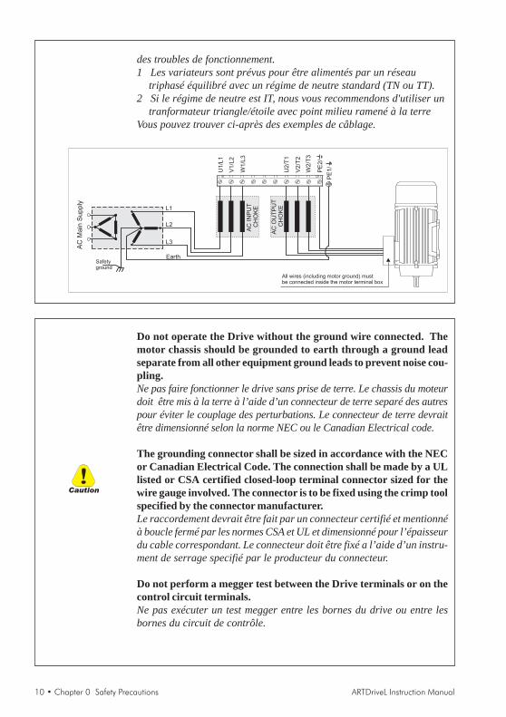
Power supply and grounding / Attention ! Alimentation puissance etmise à la terreIn case of a three phase supply not symmetrical to ground, an insulationloss of one of the devices connected to the same network can causefunctional problem to the drive, if the use of a wye/delta transformer isavoided.1 The drives are designed to be powered from standard three phase
lines that are electrically symmetrical with respect to ground (TN orTT network).
2 In case of supply with IT network, the use of wye/delta transformeris mandatory, with a secondary three phase wiring referred toground.
Please refer to the following connection sample.
Si le réseau n'est pas équilibré par rapport à la terre et qu'il n'y a pasde transformateur raingle/étoile, une mauvaise isolation d'un appareilélectrique connecté au même réseau que le variateur peut lui causer
Warning
10 • Chapter 0 Safety Precautions ARTDriveL Instruction Manual
des troubles de fonctionnement.1 Les variateurs sont prévus pour être alimentés par un réseau
triphasé équilibré avec un régime de neutre standard (TN ou TT).2 Si le régime de neutre est IT, nous vous recommendons d'utiliser un
tranformateur triangle/étoile avec point milieu ramené à la terreVous pouvez trouver ci-après des exemples de câblage.
Safetyground
L1
L2
L3
Earth
U1/L
1
V1/L
2
W1/L
3
U2/T
1
V2/T
2
W2/T
3
PE
2/
All wires (including motor ground) mustbe connected inside the motor terminal box
AC
OU
TP
UT
CH
OK
E
AC
Ma
inS
up
ply
AC
INP
UT
CH
OK
E
PE
1/
Do not operate the Drive without the ground wire connected. Themotor chassis should be grounded to earth through a ground leadseparate from all other equipment ground leads to prevent noise cou-pling.Ne pas faire fonctionner le drive sans prise de terre. Le chassis du moteurdoit être mis à la terre à l’aide d’un connecteur de terre separé des autrespour éviter le couplage des perturbations. Le connecteur de terre devraitêtre dimensionné selon la norme NEC ou le Canadian Electrical code.
The grounding connector shall be sized in accordance with the NECor Canadian Electrical Code. The connection shall be made by a ULlisted or CSA certified closed-loop terminal connector sized for thewire gauge involved. The connector is to be fixed using the crimp toolspecified by the connector manufacturer.Le raccordement devrait être fait par un connecteur certifié et mentionnéà boucle fermé par les normes CSA et UL et dimensionné pour l’épaisseurdu cable correspondant. Le connecteur doit être fixé a l’aide d’un instru-ment de serrage specifié par le producteur du connecteur.
Do not perform a megger test between the Drive terminals or on thecontrol circuit terminals.Ne pas exécuter un test megger entre les bornes du drive ou entre lesbornes du circuit de contrôle.
Caution
ARTDriveL Instruction Manual Chapter 0 Safety Precautions • 11
Because the ambient temperature greatly affects Drive life and reli-ability, do not install the Drive in any location that exceeds the allow-able temperature. Leave the ventilation cover attached for tempera-tures of 104° F (40° C) or below.Étant donné que la température ambiante influe sur la vie et la fiabilitédu drive, on ne devrait pas installer le drive dans des places ou la tem-perature permise est dépassée. Laisser le capot de ventilation en placepour températures de 104°F (40°C) ou inférieures.
If the Drive’s Fault Alarm is activated, consult the TROUBLESHOOT-ING section of this instruction book, and after correcting the problem,resume operation. Do not reset the alarm automatically by externalsequence, etc.Si la Fault Alarm du drive est activée, consulter la section du manuel concernantles défauts et après avoir corrigé l’erreur, reprendre l’opération. Ne pasréiniliatiser l’alarme automatiquement par une séquence externe, etc
Be sure to remove the desicant dryer packet(s) when unpacking theDrive. (If not removed these packets may become lodged in the fan orair passages and cause the Drive to overheat).Lors du déballage du drive, retirer le sachet déshydraté. (Si celui-ci n’estpas retiré, il empêche la ventilation et provoque une surchauffe du drive).
The Drive must be mounted on a wall that is constructed of heat re-sistant material. While the Drive is operating, the temperature of theDrive's cooling fins can rise to a temperature of 194° F (90°C).Le drive doit être monté sur un mur construit avec des matériaux résistantsà la chaleur. Pendant le fonctionnement du drive, la température desailettes du dissipateur thermique peut arriver à 194°F (90°).
Do not touch or damage any components when handling the device.The changing of the isolation gaps or the removing of the isolationand covers is not permissible.Manipuler l’appareil de façon à ne pas toucher ou endommager desparties. Il n’est pas permis de changer les distances d’isolement ou biend’enlever des matériaux isolants ou des capots.
Protect the device from impermissible environmental conditions (tem-perature, humidity, shock etc.)Protéger l’appareil contre des effets extérieurs non permis (température,humidité, chocs etc.).
No voltage should be connected to the output of the drive (terminals U2, V2W2). The parallel connection of several drives via the outputs and the directconnection of the inputs and outputs (bypass) are not permissible.Aucune tension ne doit être appliquée sur la sortie du convertisseur(bornes U2, V2 et W2). Il n’est pas permis de raccorder la sortie de
Caution

12 • Chapter 0 Safety Precautions ARTDriveL Instruction Manual
plusieurs convertisseurs en parallèle, ni d’effectuer une connexion directede l’entrée avec la sortie du convertisseur (Bypass).
A capacitative load (e.g. Var compensation capacitors) should not beconnected to the output of the drive (terminals U2, V2, W2).Aucune charge capacitive ne doit être connectée à la sortie du convertisseur(bornes U2, V2 et W2) (par exemple des condensateurs de mise en phase).
The electrical commissioning should only be carried out by qualifiedpersonnel, who are also responsible for the provision of a suitableground connection and a protected power supply feeder in accord-ance with the local and national regulations. The motor must be pro-tected against overloads.La mise en service électrique doit être effectuée par un personnel qualifié.Ce dernier est responsable de l’existence d’une connexion de terre adéquateet d’une protection des câbles d’alimentation selon les prescriptions lo-cales et nationales. Le moteur doit être protégé contre la surcharge
No dielectric tests should be carried out on parts of the drive. A suit-able measuring instrument (internal resistance of at least 10 kΩΩΩΩΩ/V)should be used for measuring the signal voltages.Il ne faut pas éxécuter de tests de rigidité diélectrique sur des parties duconvertisseurs. Pour mesurer les tensions, des signaux, il faut utiliser desinstruments de mesure appropriés (résistance interne minimale 10 kΩ/V).
NOTE! If the Drives have been stored for longer than two years, the operation ofthe DC link capacitors may be impaired and must be “reformed”.Before commissioning devices that have been stored for long periods,connect them to a power supply for two hours with no load connected inorder to regenerate the capacitors, (the input voltage has to be appliedwithout enabling the drive).En cas de stockage des variateurs pendant plus de deux ans, il est conseilléde contrôler l'état des condensateurs CC avant d'en effectuer lebranchement. Avant la mise en service des appareils, ayant été stockéspendant longtemps, il faut alimenter variateurs à vide pendant deuxheures, pour régénérer les condensateurs : appliquer une tensiond'alimentation sans actionner le variateur .
NOTE! The terms “Inverter”, “Controller” and “Drive” are sometimes usedinterchangably throughout the industry. We will use the term “Drive” inthis document.Les mots “Inverter”, “Controller” et “Drive” sont interchangeables dansle domaine industriel. Nous utiliserons dans ce manuel seulement le mot“Drive”.
Caution

ARTDriveL Instruction Manual Chapter 1 Functions and General Features • 13
Chapter 1 - Functions and General Features
1.1 Drive
The ARTDrive Lift is a field-oriented vector drive with excellent speedcontrol properties and a high torque dedicated to elevator industry and ingeneral to hoisting applications. It can be applied to both geared and gearlesssystems.Available control modes according to the installed firmware are:
AVy ... AC / AVy ... AC4 AVy ... BR / AVy ... BR4Asynchronous motor firmware Synchronous motor firmware
Control - Field oriented vector control -Brushless controlModes - Sensorless vector control
- V/f advanced control
Dedicated features
• Lift sequenceTypical sequence of input / output signals used in elevator application,brake, output contactor & door control
• Parameters in linear unitsIt is possible to select different engineering units for principal parametersdetermining the movement, rpm for speed and rpm/s, rmp/s2 foracceleration referred to motor or mm/s for speed, mm/s2, mm/s3 foracceleration referred to car.
• Lift mechanical parametersParameters of mechanical system like Pulley diameter and Gearboxratio for transformation between unit systems and System weights tocalculate inertia and tune speed regulator for desired response.
• Ramp generationTwo independent S ramps selectable through digital input with 4independent jerk settings. Dedicated deceleration ramp correspondingto stop command.
• Multi speed8 preset speed reference values. At start, possibility to overwrite withadditional value to achieve smooth start.
• Pre-torqueInitialisation of speed regulator from weight sensor to avoid saging orlifting at start.
• Landing controlPrecision control of car position in floor zone through internal positionregulator.
• Higher overloadOverload capability corresponding to typical load cycle used in elevatorapplication.
• Fan control logic function (only for sizes AVy2040AC4 / BR4 up toAVy5550AC4 / BR4)
14 • Chapter 1 Functions and General Features ARTDriveL Instruction Manual
Fan control logic function allows to run internal inverter fans onlywhen the drive is enabled. Fan control logic function signal is alsorepeated on the drive power board FEXT terminals, for an auxiliaryexternal fan.
• Emergency Module SupplyEmergency Module Supply control (EMS or MW22U) allowsemergency lift maneuvres (auxiliary battery pack is required). Bothdevices must be signal interfaced with drive power board EM terminal.Please refer to EMS or MW22U user manual for technical specification.
• Easy of use menuMenus with elevator terminology separated for MONITORing, motorSTARTUP and TRAVEL settings.
Drive features
• Self tuning procedure for current, flux and speed regulators, automaticphasing for brushless motors.
• Space vector modulation keeps the noise level to a minimum.• Switching frequencies selectable 2, 4, 8, 12, 16 kHz.• Output voltage up to 98% of input voltage.• Fault register storing the last 30 fault alarms with the associated lifetime.• Overload protection for drive, motor and brake unit.• Three freely configurable analog inputs on the standard device.• Expansion of the analog / digital outputs and analog / digital inputs via
option cards (EXP D8R4, EXP D14A4F).• Speed and torque current regulation possible.• Management of many different types of speed feeedback devices
(encoder).• Adaptive speed regulation.• Speed-related alarms.
Simple operation of the drive can be via- the terminal strip- the user-friendly keypad- the PC program supplied and the RS485 serial interface- a fieldbus connection (optional): INTERBUS-S, PROFIBUS-DP,
GENIUS, CANopen or DeviceNet.
The Drives are fitted with IGBTs (insulated gate bipolar transistors).The output is protected against ground fault and phase to phase outputshort circuit.Regulator power supply via switched-mode power supply unit from theDC Bus circuit. Power supply backup in the event of short-term voltagedips.Galvanic isolation between control section and command terminals.Analog inputs designed as differential inputs.

ARTDriveL Instruction Manual Chapter 1 Functions and General Features • 15
1.2 Motors
The AVy Drives designed for the field oriented regulation of standardthree-phase induction AC motors. A sinusoidal encoder or digital encodercan be used for feedback in proportion to speed.
The electrical and mechanical data of standard three-phase motors refersto a particular operating range. The following points should be noted whenthese motors are connected to an AC Drive:
Is it possible to use standard induction motors?With the AVy Drives it is possible to use standard induction motors. Somefeatures of the motor have a great influence on the obtained performances.Notice also what is stated in section 2.3.2, “AC Output”, about the voltagesand the motor power.
Which properties of the asynchronous motors have an unfavorableresult in operation with frequency inverters?Motors with double squirrel-cage rotors or deep rotor bars should not beused.
Star or delta connection?Motors can be connected in both star or delta connections. Experience hasshown that star connected motors have better control properties, so starconnections are preferred.
CoolingThe cooling of three-phase motors is normally implemented by means of afan that is mounted on the motor shaft. Remember that the air flux producedby the fan is reduced when the motor is running at lower speeds, which incertain circumstances may mean that the cooling is insufficient for themotor. Check with the motor manufacturer whether an external fan isrequired and the motor speed range in the application concerned.
Operation above the rated speedDue to the mechanical factors involved (bearings, unbalance of rotor) anddue to the increased iron losses, consult the manufacturer of the motor ifthis is operated above the rated speed .
What motor data is required for connecting the frequency inverter?Motor nameplate specifications
Asynchronous induction motor- Rated voltage - Rated power- Rated frequency - Cosphi- Rated current - Efficiency- Rated speed

16 • Chapter 1 Functions and General Features ARTDriveL Instruction Manual
Synchronous brushless motor- Rated voltage - Torque constant- Rated current - EMF constant- Rated speed - Stator resistance- Pole pairs - Ls S inductance
Motor protectionThermistorsPTC thermistors according to DIN 44081 or 44082 fitted in the motor canbe connected directly to the frequency inverter via terminals 78 and 79. Inthis case the resistor (1Kohm) mounted between the terminals 78 and 79has to be removed.
Temperature-dependent contacts in the motor windingTemperature-dependent contacts “Klixon” type can disconnect the drivevia the external control or can be reported as an external fault on thefrequency inverter (terminal 15). They can also be connected to the terminals78 and 79 in order to have a specific error signal. In this case connect theexisting 1 Kohm resistor in series to the wiring, note that one side of itmust be connected directly to terminal 79.
NOTE! The motor PTC interface circuit (or klixon) has to be considered andtreated as a signal circuit. The connections cables to the motor PTC mustbe made of twisted pairs with a shield, the cable route should not be parallelto the motor cable or far away at least 20 cm.
Current limitation of the frequency inverterThe current limitation can protect the motor from impermissible overloads.For this the current limitation and the motor overload control function ofthe Drive (“Motor protection”) must be set so that the current is kept withinthe permissible range for the motor concerned.
NOTE! Remember that the current limitation can control an overheating of themotor only due to overload, not due to insufficient ventilation. When thedrive is operated at low speeds the additional use of PTC resistors ortemperature-dependent contacts in the motor windings is recommended,unless separate forced ventilation is available.
Output chokesWhen using general purpose standard motors, output chokes arerecommended to protect winding isolation in some cases. See section 4.8.2,“Output chokes”.

ARTDriveL Instruction Manual Chapter 2 Inspection procedures, Components Identification and Std Specs •17
Chapter 2 - Inspection procedures, Components Identification andStandard Specifications
2.1 Upon Delivery Inspection Procedures
2.1.1 General
A high degree of care is taken in packing the ARTDriveL drives andpreparing them for delivery. They should only be transported with suitabletransport equipment (see weight data). Observe the instructions printed onthe packaging. This also applies when the device is unpacked and installedin the control cabinet.
Upon delivery, check the following:• the packaging for any external damage• whether the delivery note matches your order.Open the packaging with suitable tools. Check whether:• any parts were damaged during transport• the device type corresponds to your order
In the event of any damage or of an incomplete or incorrect delivery pleasenotify the responsible sales offices immediately.The devices should only be stored in dry rooms within the specifiedtemperature ranges.
NOTE! A certain degree of moisture condensation is permissible if this arisesfrom changes in temperature (see section 2.3.1, “Permissible EnvironmentalConditions”). This does not, however, apply when the devices are inoperation. Always ensure that there is no moisture condensation in devicesthat are connected to the power supply!
2.1.2 Inverter type designation
The technical specification of the AVy Drive is stated in the type code.Example:
AVy2040-XXX-AC4
ARTDrive, AC flux vector drive, 3 phase input voltageEnclosure dimension identificationNominal motor output = 4kWX=KCS led module, K=programmable KBS keypadX=without internal brake transistor, B=with internal brake transistorX=standard software, L=LIFT software (specific for lift control)AC=Firmware for asynchronous induction motors, BR=Firmware for synchronous brushless motors4=Hardware Lift for internal / external logic fan control and emergency module supplier control (AVy2040 ... AVy5550 sizes only), [blank]=Hardware standard
18 • Chapter 2 Inspection procedures, Components Identification and Std Specs ARTDriveL Instruction Manual
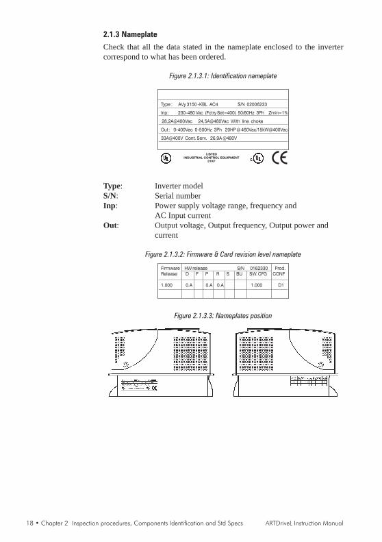
2.1.3 Nameplate
Check that all the data stated in the nameplate enclosed to the invertercorrespond to what has been ordered.
Figure 2.1.3.1: Identification nameplate
Type : AVy 3150 -KBL AC4 S/N 02006233
Inp: 230-480 Vac (Fctry Set=400) 50/60Hz 3Ph Zmin=1%
28,2A@400Vac 24,5A@480Vac With line choke
Out : 0-400Vac 0-500Hz 3Ph 20HP @ 460Vac/15kW@400Vac
33A@400V Cont. Serv. 26,9A @480V
LISTED
INDUSTRIAL CONTROL EQUIPMENT
31KF
Type: Inverter modelS/N: Serial numberInp: Power supply voltage range, frequency and
AC Input currentOut: Output voltage, Output frequency, Output power and
current
Figure 2.1.3.2: Firmware & Card revision level nameplate
Firmware HW release S/N 0162330 Prod.
Release D F P R S BU SW. CFG CONF
1.000 0.A 0.A 0.A 1.000 D1
Figure 2.1.3.3: Nameplates position
ARTDriveL Instruction Manual Chapter 2 Inspection procedures, Components Identification and Std Specs •19
2.2 Component Identification
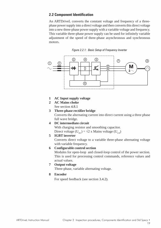
An ARTDriveL converts the constant voltage and frequency of a three-phase power supply into a direct voltage and then converts this direct voltageinto a new three-phase power supply with a variable voltage and frequency.This variable three-phase power supply can be used for infinitely variableadjustment of the speed of three-phase asynchronous and synchronousmotors.
Figure 2.2.1: Basic Setup of Frequency Inverter
1 2
3 4 5
6
7 8
1 AC Input supply voltage2 AC Mains choke
See section 4.8.13 Three-phase rectifier bridge
Converts the alternating current into direct current using a three phasefull wave bridge.
4 DC intermediate circuitWith charging resistor and smoothing capacitor.Direct voltage (UDC) = √2 x Mains voltage (ULN)
5 IGBT inverterConverts direct voltage to a variable three-phase alternating voltagewith variable frequency.
6 Configurable control sectionModules for open-loop and closed-loop control of the power section.This is used for processing control commands, reference values andactual values.
7 Output voltageThree-phase, variable alternating voltage.
8 EncoderFor speed feedback (see section 3.4.2).
20 • Chapter 2 Inspection procedures, Components Identification and Std Specs ARTDriveL Instruction Manual
2.3 Standard Specifications
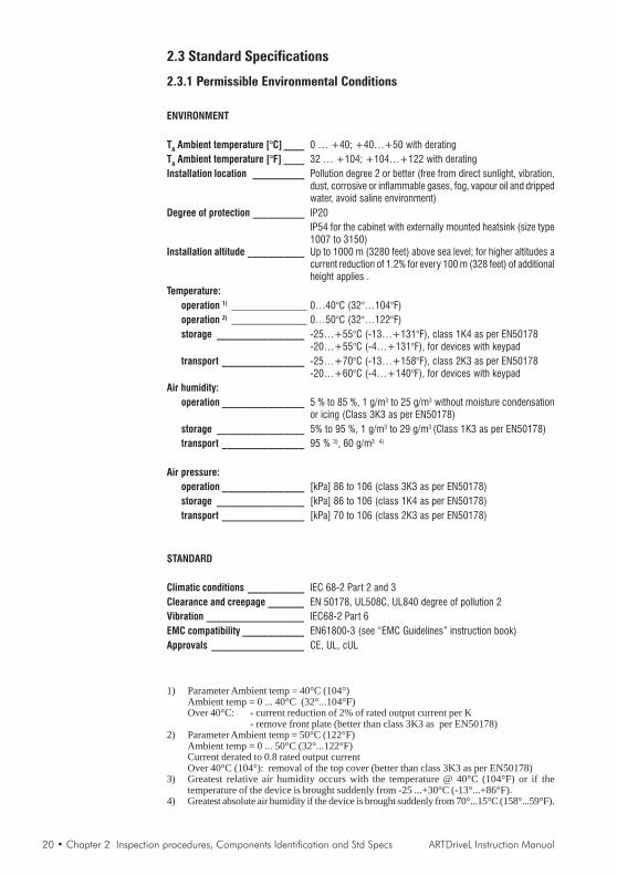
2.3.1 Permissible Environmental Conditions
ENVIRONMENT
TA Ambient temperature [°C] ____ 0 … +40; +40…+50 with deratingTA Ambient temperature [°F] ____ 32 … +104; +104…+122 with deratingInstallation location __________ Pollution degree 2 or better (free from direct sunlight, vibration,
dust, corrosive or inflammable gases, fog, vapour oil and drippedwater, avoid saline environment)
Degree of protection __________ IP20IP54 for the cabinet with externally mounted heatsink (size type1007 to 3150)
Installation altitude ___________ Up to 1000 m (3280 feet) above sea level; for higher altitudes acurrent reduction of 1.2% for every 100 m (328 feet) of additionalheight applies .
Temperature:operation 1) _________________________ 0…40°C (32°…104°F)operation 2) _________________________ 0…50°C (32°…122°F)storage _________________ -25…+55°C (-13…+131°F), class 1K4 as per EN50178
-20…+55°C (-4…+131°F), for devices with keypadtransport ________________ -25…+70°C (-13…+158°F), class 2K3 as per EN50178
-20…+60°C (-4…+140°F), for devices with keypadAir humidity:
operation ________________ 5 % to 85 %, 1 g/m3 to 25 g/m3 without moisture condensationor icing (Class 3K3 as per EN50178)
storage _________________ 5% to 95 %, 1 g/m3 to 29 g/m3 (Class 1K3 as per EN50178)transport ________________ 95 % 3), 60 g/m3 4)
Air pressure:operation ________________ [kPa] 86 to 106 (class 3K3 as per EN50178)storage _________________ [kPa] 86 to 106 (class 1K4 as per EN50178)transport ________________ [kPa] 70 to 106 (class 2K3 as per EN50178)
STANDARD
Climatic conditions ___________ IEC 68-2 Part 2 and 3Clearance and creepage _______ EN 50178, UL508C, UL840 degree of pollution 2Vibration ___________________ IEC68-2 Part 6EMC compatibility ____________ EN61800-3 (see “EMC Guidelines” instruction book)Approvals __________________ CE, UL, cUL
1) Parameter Ambient temp = 40°C (104°)Ambient temp = 0 ... 40°C (32°...104°F)Over 40°C: - current reduction of 2% of rated output current per K
- remove front plate (better than class 3K3 as per EN50178)2) Parameter Ambient temp = 50°C (122°F)
Ambient temp = 0 ... 50°C (32°...122°F)Current derated to 0.8 rated output currentOver 40°C (104°): removal of the top cover (better than class 3K3 as per EN50178)
3) Greatest relative air humidity occurs with the temperature @ 40°C (104°F) or if thetemperature of the device is brought suddenly from -25 ...+30°C (-13°...+86°F).
4) Greatest absolute air humidity if the device is brought suddenly from 70°...15°C (158°...59°F).

ARTDriveL Instruction Manual Chapter 2 Inspection procedures, Components Identification and Std Specs •21
DISPOSAL OF THE DEVICE
The AVy Drive can be disposed as electronic scrap in accordance with thecurrently valid national regulations for the disposal of electronic parts.The plastic covers of the Drives (up to size 3150) are recyclable: the materialused is >ABS+PC< .
2.3.2 AC Input/Output Connection
The AVy Drive must be connected to an AC mains supply capable ofdelivering a symmetrical short circuit current (at 480V +10% Vmax) loweror equal to the values indicated on table 2.3.4.1. For the use of an AC inputchoke see chapter 4.8.1.No external connection of the regulator power supply to the existing ACInput supply is required since the power supply is taken from the DC Linkcircuit. When commissioning, set the Mains voltage parameter to the valueof the AC Input voltage concerned. This automatically sets the thresholdfor the Undervoltage alarm at the appropriate level.
NOTE! In some cases AC Input chokes, and possibly noise suppression filters shouldbe fitted on the AC Input side of the device. See chapter “Chokes/Filters”.
Adjustable Frequency Drives and AC Input filters have ground dischargecurrents greater then 3.5 mA. EN 50178 specifies that with dischargecurrents greater than 3.5 mA the protective conductor ground connection(PE1) must be fixed type.
2.3.3 AC Input
The Input current of the Drive depends on the operating state and the serviceconditions of the connected motor, and the use of input reactors. The table2.3.4.1 shows the values corresponding to rated continuous service (IEC146 class 1), keeping into account typical output power factor for each size
2.3.4 AC Output
The output of the AVy Drive is ground fault and phase to phase shortprotected. The switching frequency is constant in the speed range anddepends on the drive size.The connection of an external voltage to the output terminals of the Driveis not permitted!
NOTE! It is allowed to disconnect the motor from the Drive output, by meansof output contactor only after the Drive has been disabled.

22 • Chapter 2 Inspection procedures, Components Identification and Std Specs ARTDriveL Instruction Manual
The value for the continuous output current rating ( ICONT ) depends onAC Input voltage ( KV ), Ambient temperature ( KT ) and Switchingfrequency ( KF ), values of derating factor are the listed on table 2.3.4.1:
ICONT = I2N x KV x KT x KF
The applicable deratings are automatically set when selecting theappropriate values of AC Input voltage, Ambient temperature andSwitching frequency.
Figure 2.3.4.1: Rating of Drive in Function of Switching Frequency
2kHz 4kHz 8kHz 12kHz 16kHz
100%
70%
85%
105%
110%
Rated drive current@400V
[%]
0.75-37kW
45-160kW
Over-rating only on 2.2, 4, 5.5, 18.5kW
Switching frequency[kHz]
Default Higher
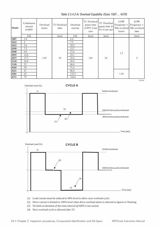
Table 2.3.4.2 shows overload current values for typical service profiles(Ambient temperature =40°C [104°F], standard switching frequency).
After overload cycle, the output current is reduced to nominal outputcurrent by the drive control. In order to allow next overload cycle, outputcurrent should be decreased (reducing the load) to value less then nominal.Table states overload recovery (pause) time with current reduced to 90%continuous current.
The coordination of the motor rated powers with the Drive type presentedin the table below refers to the use of standard 4 poles motors with a ratedvoltage equal to the rated voltage of the input supply.As for those motors with different voltages, the type of Drive to use isdetermined by the rated current of the motor.
Motor nominal current cannot be lower than 0,3 x I2N . Magnetizingmotor current must not be higher of ICONT.

ARTDriveL Instruction Manual Chapter 2 Inspection procedures, Components Identification and Std Specs •23
Table 2.3.4.1: AC Input/Output Specifications
4220
4300
4370
4221
4301
4371
Inve
rter
Ou
tpu
t(I
EC
146
clas
s1),
Co
nti
nu
ou
sse
rvic
e[k
VA
]1.
62.
73.
85
6.5
8.5
1216
.822
.426
.532
4255
6479
9812
814
517
322
4P
Nm
ot
(rec
om
men
ded
mo
tor
ou
tpu
t):
@U
LN
=23
0Vac
;f S
W=
def
ault
;IE
C14
6cl
ass
1[k
W]
0.37
0.75
1.1
1.5
2.2
34
5.5
7.5
911
18.5
2222
3037
5555
7590
@U
LN
=40
0Vac
;f S
W=
def
ault
;IE
C14
6cl
ass
1[k
W]
0.75
1.5
2.2
34
5.5
7.5
1115
18.5
2230
3745
5575
9011
013
216
0
@U
LN
=46
0Vac
;IE
C14
6cl
ass
1[H
p]
12
33
57.
510
1520
2330
4050
6075
100
125
150
150
200
U2
Max
ou
tpu
tvo
ltag
e[V
]
f 2M
axo
utp
ut
freq
uen
cy(*
)[H
z]
I 2N
Rat
edo
utp
ut
curr
ent
:
@U
LN
=23
0-40
0Vac
;f S
W=
def
ault
;IE
C14
6cl
ass
1[A
]2.
44
5.6
7.5
9.6
12.6
17.7
24.8
3339
4763
7993
114
142
185
210
250
324
@U
LN
=46
0Vac
;f S
W=
def
ault
;IE
C14
6cl
ass
1[A
]2.
13.
54.
96.
58.
311
15.4
21.6
28.7
3440
5468
8199
124
160
183
217
282
f SW
swit
chin
gfr
equ
ency
(Def
ault
)[k
Hz]
f SW
swit
chin
gfr
equ
ency
(Hig
her
)[k
Hz]
--D
erat
ing
fact
or:
KV
at46
0/48
0Vac
0.96
0.87
0.93
0.90
KT
for
amb
ien
tte
mp
erat
ure
KF
for
swit
chin
gfr
equ
ency
UL
NA
CIn
pu
tvo
ltag
e[V
]
AC
Inp
ut
freq
uen
cy[H
z]
I NA
CIn
pu
tcu
rren
tfo
rco
nti
nu
ou
sse
rvic
e:
-C
on
nec
tio
nw
ith
3-p
has
ere
acto
r
@23
0Vac
;IE
C14
6cl
ass1
[A]
1.7
2.9
45.
57
9.5
1418
.225
32.5
3955
6984
9812
215
819
222
0n
.a.
@40
0Vac
;IE
C14
6cl
ass1
[A]
1.9
3.3
4.5
6.2
7.9
10.7
15.8
20.4
28.2
36.7
4462
7794
110
137
177
216
247
309
@46
0Vac
;IE
C14
6cl
ass1
[A]
1.7
2.9
3.9
5.4
6.7
9.3
13.8
17.8
24.5
32.5
3753
6682
9612
015
318
821
426
8-
Co
nn
ecti
on
wit
ho
ut
3-p
has
ere
acto
r @23
0Vac
;IE
C14
6cl
ass1
[A]
3.6
4.4
6.8
7.9
1115
.521
.527
.935
.4
@40
0Vac
;IE
C14
6cl
ass1
[A]
3.9
4.8
7.4
912
16.9
24.2
30.3
40
@46
0Vac
;IE
C14
6cl
ass1
[A]
3.4
4.2
6.4
7.8
10.4
14.7
2126
.434
.8
Max
sho
rtci
rcu
itp
ow
erw
ith
ou
tli
ne
reac
tor
(Zm
in=
1%)
[kV
A]
160
270
380
500
650
850
1200
1700
2250
2700
3200
4200
5500
6400
7900
9800
1280
014
500
1730
022
400
[V]
[V]
(*)
Max
ou
tpu
tfr
equ
ency
refe
rto
regu
lati
on
infi
eld
ori
ente
dm
od
e.S
eeta
ble
atch
apte
r3.
3.6
for
oth
erd
etai
lsT
AD
L20
10
Fo
rA
Vy…
AC
4an
dA
Vy…
BR
4se
ries
on
lyth
em
od
els
on
grey
fiel
dar
eav
aila
ble
.
7900
71100
71320
81600
4185
5450
5550
6750
2055
2075
3110
3150
1015
1022
1030
2040
0.87
8
4
0.98
xU
LN
(AC
Inp
ut
volt
age)
400 8
200
0.87
Typ
e1007
12/
16
Bra
kin
gIG
BT
Un
it(s
tan
dar
dd
rive
)
O U T P U T I N P U T
Ove
rvo
ltag
eth
resh
old
Un
der
volt
age
thre
sho
ld
230
V-1
5%...
480
V+
10%
,3P
h
230
VD
C(f
or
230
VA
Cm
ain
s),4
00V
DC
(fo
r40
0VA
Cm
ain
s),4
60V
DC
for
460
VA
Cm
ain
s)
Op
tio
nin
tern
al(w
ith
exte
rnal
resi
sto
r);
Bra
kin
gto
rqu
e15
0%
0.8
@50
°C(1
22°F
)
Fo
rth
ese
typ
esan
exte
rnal
ind
uct
ance
isre
com
men
ded
Ext
ern
alb
rak
ing
un
it(o
pti
on
al)
50/6
0H
z±
5%
820
VD
C
Sta
nd
ard
inte
rnal
(wit
hex
tern
alre
sist
or)
;B
rak
ing
torq
ue
150%
0.7
for
f SW
=16
,0.
85fo
rf S
W=
120.
7fo
rf S
Wh
igh
erth
end
efau
lt
24 • Chapter 2 Inspection procedures, Components Identification and Std Specs ARTDriveL Instruction Manual
Table 2.3.4.2-A: Overload Capability (Sizes 1007 ... 4370)
Continuous
current
@400V
Overload
factor
T1 Overload
time
Overload
current
T2 Overload
pause time
@90% Cont
curr
T3 Overload
pause time @
0% Cont curr
LOW
Frequency <
3Hz overload
factor
LOW
Frequency <
3Hz overload
time
[A] [sec] [A] [sec] [sec] [sec]1007 2.4 4.4
1015 4 7.3
1022 5.6 10.2
1030 7.5 13.7
2040 9.6 17.6
2055 12.6 23.1
2075 17.7 32.4
3110 24.8 45.4
3150 33 60.4
4185 39 71.4
4221 47 86.0
4301 63 115.3
4371 79 144.6
TL2020
2
1.5
1.36
10 124 24
Model
1.83
OvldCurrentLevel
Overload Level [%]
Time [sec]
T1
T2
OvldCurrentLevel
Overload Level [%]
Time [sec]T3
CYCLE A
100%ContinuousCurrentLevel
90%ContinuousCurrentLevel
(1)
(2)
CYCLE B
(3)
(4)
T1
100%ContinuousCurrentLevel
(1) Load current must be reduced to 90% level to allow next overload cycle.(2) Drive current is limited to 100% level when drive overload alarm is selected as Ignore or Warning(3) No limit on duration of this time interval @100% Cont current(4) Next overload cycle is allowed after T3

ARTDriveL Instruction Manual Chapter 2 Inspection procedures, Components Identification and Std Specs •25
Table 2.3.4.2-B: Overload Capability (Sizes 5450... 81600)
Continuous
current
@400V
SLOW
Overload
factor
T1 SLOW
Overload
time
SLOW
Overload
current
T2 SLOW
Overload
pause time
@90%
Cont curr
FAST
Overload
factor
TF FAST
Overload
time [sec]
FAST
Overload
current
LOW
Frequency
< 3Hz
overload
factor
LOW
Frequency
< 3Hz
overload
time
[A] [sec] [A] [sec] [sec] [A] [sec]
5450 93 126.5 170.2
5550 114 155 208.6
6750 142 193.1 259.9
7900 185 251.6 338.6
71100 210 285.6 384.3
71320 250 340 457.5
81600 324 440.6 1.4 1.0 453.6
TL2021
21.36
Model
0.51.36 60 300
1.83
FastOvldCurrentLevel
SlowOvldCurrentLevel
100%ContinuousCurrentLevel
90%ContinuousCurrentLevel
Overload Level [%]
Time [sec]
TF
T1
T2
Load current must be reduced to 90% level
to allow next overload cycle
Drive current is limited to 100% level
when drive overload alarm is selected
as Ignore or Warning

26 • Chapter 2 Inspection procedures, Components Identification and Std Specs ARTDriveL Instruction Manual
2.3.5 I/O and Encoder SpecificationsI/OEnable inputs ________________ 0 / 15...30 V 3.2...6.4 mA (5 mA @ 24 V)Analog inputs ________________ Selectable 0... ± 10 V 0.25mA max
0...20 mA 10V max4...20 mA 10 V maxMax common mode voltage: 0...± 10 V
Analog outputs _______________ 0...± 10 V 5 mA max per outputDigital inputs ________________ 0 / 15...30 V 3.2...6.4 mA (5 mA @ 24 V)
Digital outputs _______________ Supply + 15...35 VSignals + 15...35 V 40 mA max per output
Int. voltage supplyLoad capacity _______________ + 5 V, 160 mA Plug connector
+ 10 V, 10 mA Terminal 7- 10 V, 10 mA Terminal 8+ 24 V, 120 mA Terminal 19
Tolerance ___________________ + 10 V ± 3 % 1)
- 10 V ± 3 % 1)
+ 24 V + 20 ... 30 V, not stabilizedXE for digital encoder, PIN 7/9
1)The tolerance between positive and negative amplitudes is ± 0.5%
2.3.6 Accuracy
Table 2.3.6.1: Maximum / Minimum Output Frequency
(a): 1.5 * Rated motor torque capability
Regulation modeMaximum
Switching frequency (kHz)
Minimum (a)
44444
200
200
300
200
88888
400
200
600
400
1616161616
400
200
600
400
Field oriented
Sensorless vect
V/f control
Brushless
Resolution
22222
200
200
200
200
0
0.6
2*motor slip freq
0
0.005
Output frequency (Hz)
ARTDriveL Instruction Manual Chapter 2 Inspection procedures, Components Identification and Std Specs •27
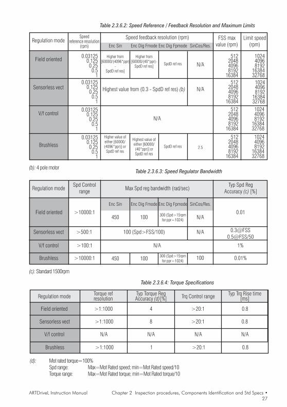
Table 2.3.6.2: Speed Reference / Feedback Resolution and Maximum Limits
Table 2.3.6.3: Speed Regulator Bandwidth(b): 4 pole motor
(c): Standard 1500rpm
Regulation mode Limit speed(rpm)
0.031250.1250.250.5
1
Speed feedback resolution (rpm)
Field oriented
Sensorless vect
V/f control
FSS maxvalue (rpm)
Speedreference resolution
(rpm)
0.031250.1250.250.5
1
0.031250.1250.250.5
1
Enc Sin Enc Dig Fmode Enc Dig Fpmode
Higher from[60000/(4096*ppr)
-SpdD ref res]
SpdD ref res
Highest value from (0.3 - SpdD ref res) (b)
N/A
512204840968192
16384512
204840968192
16384512
204840968192
16384
102440968192
1638432768
102440968192
1638432768102440968192
1638432768
Higher from[60000/(40*ppr)-
SpdD ref res]
Brushless0.03125
0.1250.250.5
1
512204840968192
16384
102440968192
1638432768
Higher value ofeither [60000/(4096*ppr)] or
SpdD ref resSpdD ref res
Highest value ofeither [60000/(40*ppr)] orSpdD ref res
SinCos/Res.
2.5
N/A
N/A
Regulation modeTyp Spd Reg
Accuracy (c) [%]Max Spd reg bandwidth (rad/sec)Spd Control
range
Field oriented
Sensorless vect
V/f control
100 (Spd>FSS/100)
N/A
>10000:1
>500:1
>100:1
450 100 300 (Spd>15rpmfor ppr=1024)
0.01
[email protected]@FSS/50
1%
100
Enc Sin Enc Dig Fmode Enc Dig Fpmode SinCos/Res.
Brushless
N/A
>10000:1 0.01%
N/A
450 100 300 (Spd>15rpmfor ppr=1024)
Table 2.3.6.4: Torque Specifications
Regulation mode
Field oriented
Sensorless vect
V/f control
Torque refresolution
>1:1000
>1:1000
N/A
Typ Torque RegAccuracy (d)[%]
4
8
N/A
Trq Control range
>20:1
>20:1
N/A
Typ Trq Rise time[ms]
0.8
0.8
N/A
(d): Mot rated torque=100%Spd range: Max=Mot Rated speed; min=Mot Rated speed/10Torque range: Max=Mot Rated torque; min=Mot Rated torque/10
Brushless >1:1000 1 >20:1 0.8

28 • Chapter 3 Installation Guidelines ARTDriveL Instruction Manual
Chapter 3 - Mechanical Installation Guidelines
3.1 Dimensions and Mounting Methods
Figure 3.1.1: Drive Dimensions (Sizes 1007 ... 3150)
c a
b
D1
D2
d
E2
E1
aD1
D2
E2
E1
Figure 3.1.2: Mounting Methods (Sizes 1007 ... 3150)
Mounting wall (D)Mounting with external dissipator (E)
E2 E4
E5
E3
E1
Ø d

ARTDriveL Instruction Manual Chapter 3 Installation Guidelines • 29
Table 3.1.1: Drive Dimensions and Weights (Sizes 1007 ... 3150)
1007 1015 1022 1030 2040 2055 2075 3110 3150
a mm (inch)
b mm (inch)
c mm (inch)
d mm (inch)
D1 mm (inch)
D2 mm (inch)
E1 mm (inch)
E2 mm (inch)
E3 mm (inch)
E4 mm (inch)
E5 mm (inch)
Ø d
Weight kg (lbs) 3.5 (7.7) 3.6 (7.9)tadl3100
8.6 (19)3.7 (8.1) 4.95 (10.9)
M5
Type
306.5 (12.0)
105.5 (4.1) 151.5 (5.9)
Drive dimensions:
310.5 (12.2)
164 (6.5)
296.5 (11.6)
299.5 (11.7)
69 (2.7)
315 (12.4)
208 (8.2)
323 (12.7)
240 (9.5)
168 (6.6)
84 (3.3)
115 (4.5)
115 (4.5)
199.5 (7.8)
69 (2.7)
62 (2.4)
9 (0.35)
299.5 (11.8)
99.5 (3.9) 145.5 (5.7) 199 (7.8)
284 (11.2)
Figure 3.1.3: Drive Dimensions (Sizes 4220 ... 81600)
caD1
b
30 • Chapter 3 Installation Guidelines ARTDriveL Instruction Manual
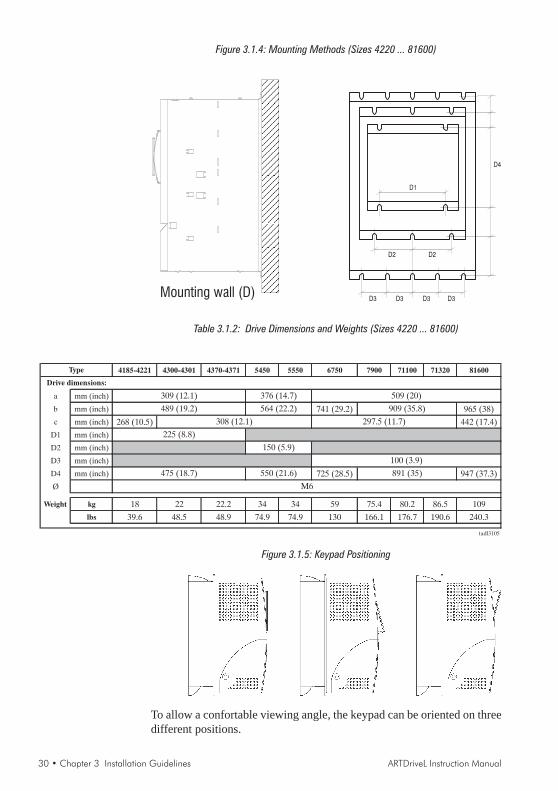
Figure 3.1.4: Mounting Methods (Sizes 4220 ... 81600)
D1
D2 D2
D3 D3 D3 D3
D4
Mounting wall (D)
Table 3.1.2: Drive Dimensions and Weights (Sizes 4220 ... 81600)
4185-4221 4300-4301 4370-4371 5450 5550 6750 7900 71100 71320 81600
a mm (inch)
b mm (inch) 741 (29.2) 965 (38)
c mm (inch) 268 (10.5) 442 (17.4)
D1 mm (inch)
D2 mm (inch)
D3 mm (inch)
D4 mm (inch) 725 (28.5) 947 (37.3)
Ø
Weight kg 18 22 22.2 34 34 59 75.4 80.2 86.5 109
lbs 39.6 48.5 48.9 74.9 74.9 130 166.1 176.7 190.6 240.3
tadl3105
Drive dimensions:
309 (12.1) 509 (20)
489 (19.2) 564 (22.2)
376 (14.7)
909 (35.8)
Type
M6
150 (5.9)
550 (21.6)
100 (3.9)
225 (8.8)
308 (12.1) 297.5 (11.7)
891 (35)475 (18.7)
Figure 3.1.5: Keypad Positioning
To allow a confortable viewing angle, the keypad can be oriented on threedifferent positions.
ARTDriveL Instruction Manual Chapter 3 Installation Guidelines • 31
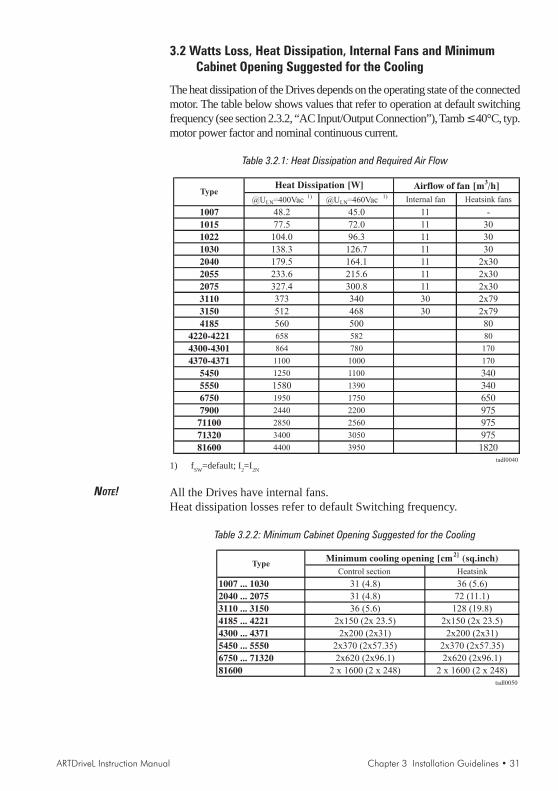
3.2 Watts Loss, Heat Dissipation, Internal Fans and MinimumCabinet Opening Suggested for the Cooling
The heat dissipation of the Drives depends on the operating state of the connectedmotor. The table below shows values that refer to operation at default switchingfrequency (see section 2.3.2, “AC Input/Output Connection”), Tamb ≤40°C, typ.motor power factor and nominal continuous current.
Table 3.2.1: Heat Dissipation and Required Air Flow
@ULN=400Vac1)
@ULN=460Vac1) Internal fan Heatsink fans
1007 48.2 45.0 11 -
1015 77.5 72.0 11 30
1022 104.0 96.3 11 30
1030 138.3 126.7 11 30
2040 179.5 164.1 11 2x30
2055 233.6 215.6 11 2x30
2075 327.4 300.8 11 2x30
3110 373 340 30 2x79
3150 512 468 30 2x79
4185 560 500 80
4220-4221 658 582 80
4300-4301 864 780 170
4370-4371 1100 1000 170
5450 1250 1100 340
5550 1580 1390 340
6750 1950 1750 650
7900 2440 2200 975
71100 2850 2560 975
71320 3400 3050 975
81600 4400 3950 1820tadl0040
Heat Dissipation [W] Airflow of fan [m3/h]
Type
1) fSW=default; I2=I2N
NOTE! All the Drives have internal fans.Heat dissipation losses refer to default Switching frequency.
Table 3.2.2: Minimum Cabinet Opening Suggested for the Cooling
Control section Heatsink
1007 ... 1030 31 (4.8) 36 (5.6)
2040 ... 2075 31 (4.8) 72 (11.1)
3110 ... 3150 36 (5.6) 128 (19.8)
4185 ... 4221 2x150 (2x 23.5) 2x150 (2x 23.5)
4300 ... 4371 2x200 (2x31) 2x200 (2x31)
5450 ... 5550 2x370 (2x57.35) 2x370 (2x57.35)
6750 ... 71320 2x620 (2x96.1) 2x620 (2x96.1)
81600 2 x 1600 (2 x 248) 2 x 1600 (2 x 248)
tadl0050
Minimum cooling opening [cm2]
(sq.inch)Type

32 • Chapter 3 Installation Guidelines ARTDriveL Instruction Manual
3.2.1 Cooling Fans Power Supply
Fan Control Logic function(only for sizes AVy2040AC4 / BR4 up to AVy5550AC4 / BR4)It allows to run internal fans only when the drive is enabled. Fans willstop when the drive is disabled after a period of 300sec and heatsinktemperature is below 60 degrees.Fan control logic function signal is also repeated on the drive power boardFEXT terminals, for an auxiliary external fan.
Cooling Fans Power Supply for sizes AVy1007 to AVy5550Power supply (+24VAC) for these fans is provided from the internal drivepower supply unit.
Cooling Fans Power Supply for sizes AVy6750 to AVy81600Power supply for the fans is externally connected by the user. AC Inputvoltage is connected at the power terminal strip:- AVy6750: 0.8A@115V/60Hz, 0.45A@230V / 50Hz- AVy7900 ... AVy71320: 1.2A@115V/60Hz, 0.65A@230V / 50Hz- AVy81600: 1.65A@115V/60Hz, 0.70A@230V / 50Hz
Figure 3.2.1: UL Type Fans Connections on AVy7900, AVy71100 and AVy71320 Sizes
M
~
U3
2V3
1V3
0
115
230
AU
TOTR
AFO
230VAC fans
Drive
Figure 3.2.2: UL Type Fans Connections on AVy6750 and AVy81600 Sizes
M
~
U3
2V3
1V3
No.2 115VAC fansM
~
Drive
ARTDriveL Instruction Manual Chapter 3 Installation Guidelines • 33
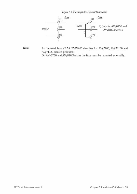
Figure 3.2.3: Example for External Connection
U3
2V3
1V3
230VAC
U3
2V3
1V3
115VAC
Drive Drive
(*)
NOTE! An internal fuse (2.5A 250VAC slo-blo) for AVy7900, AVy71100 andAVy71320 sizes is provided.On AVy6750 and AVy81600 sizes the fuse must be mounted externally.
*) Only for AVy6750 andAVy81600 drives

34 • Chapter 3 Installation Guidelines ARTDriveL Instruction Manual
3.3 Installation Mounting Clearance
NOTE! The dimensions and weights specifed in this manual should be taken intoconsideration when the device is mounted. The technical equipment required(carriage or crane for large weights) should be used. Improper handlingand the use of unsuitable tools may cause damage.
Figure 3.3.1: Max. Angle of Inclination
The maximum angle of inclination is 30°
NOTE! The drives must be mounted in such a way that the free flow of air is ensured.The clearance to the device must be at least 150 mm (6 inches). A space of atleast 50 mm (2 inches) must be ensured at the front.On size 81600 the top and bottom clearance must be at least 380 mm (15inches), on front and sides must be ensured a space of at least 140 mm (5.5inches). Devices that generate a large amount of heat must not be mounted inthe direct vicinity of the drive.
Figure 3.3.2: Mounting Clearance
10 mm ( 0.4" )[140mm (5.5")]
150 mm ( )6"[380mm (15")]
50 mm ( 2" )[140mm (5.5”)]
20 mm ( 0.8" )[140mm (5.5")]
150 mm ( )6"[380mm (15")]
10 mm ( 0.4" )[140mm (5.5")]
[...] for 81600 size
NOTE! Fastening screws should be re-tightened after a few days of operation.

ARTDriveL Instruction Manual Chapter 4 Wiring Procedure • 35
Chapter 4 - Wiring Procedure
4.1 Accessing the Connectors
4.1.1 Removing the Covers
NOTE! Observe the safety instructions and warnings given in this manual. The devicescan be opened without the use of force. Only use the tools specified.
Figure 4.1.1: Removing the Covers (Sizes 1007 to 3150)
2
1
3
2
no. 2 for20-40 ...30-60
size
Sizes 1007 to 2075:The terminal cover and cable entry plate of the device must be removed inorder to fit the electrical connections:- unscrew the screw (1), remove the cover of devices (2) by pressing on
both sides as shown on the above figure (3).- unscrew the two screws (4) to remove the cable entry plate.The top cover must be removed in order to mount option cards and changethe internal jumper settings:- remove the keypad and disconnect the connector (5)- lift the top cover on the bottom side (over the connector level) and
then push it to the top (6).
Sizes 3110 to 3150:The terminal cover and cable entry plate of the device must be removed inorder to fit the electrical connections:- unscrew the two screws (1) and remove the cover of devices- unscrew the two screws (4) to remove the cable entry plate.The top cover must be removed in order to mount the option card andchange the internal jumper settings:- remove the keypad and disconnect the connector (5)- lift the top cover on the bottom side (over the connector level) and thenpush it to the top (6)

36 • Chapter 4 Wiring Procedure ARTDriveL Instruction Manual
Figure 4.1.2: Removing the Covers (Sizes 4185 to 81600)
2 2
1
3
3
4
Sizes 4185 to 81600:The terminal cover of the device must be removed in order to fit the electricalconnections: unscrew the two screw (2) and remove the cover (1)The top cover must be removed in order to mount the option card andchange the internal jumper settings: unscrew the two screw (3) and removethe top cover by moving it as indicated on figure (4).
4.2 Power Section
Please note that a wrong connection on motor phases can cause the motorto move without control and can destroy the drive.Please check that motor phases are connected in the right sequence beforeenabling the drive.
In order to avoid damage to the drive it is notallowed to transport it by holding the cards!
Caution
Caution

ARTDriveL Instruction Manual Chapter 4 Wiring Procedure • 37
4.2.1 Terminal Assignment on Power Section / Cable Cross-SectionTable 4.2.1.1: Power Section Terminals from 1007 to 3150
Function max
Motor ground connection
Braking unit resistor command (braking resistormust be connected between BR1 and C)
Intermediate circuit connection 770V DC / 1.65output current
AC mains voltage230V -15% …
460V+15%, 3Ph
Motor connectionAC line volt 3Ph
1.36 outputcurrent
Internal braking resistor
M
3Ph~
PE1 / Grounding (protective earth) conductor
U1/L1
V1/L2
W1/L3
BR1
U2/T1
V2/T2
W2/T3
C
D
PE2/
EM
EM
FEXT
FEXT
Emergency module signal required to interface the drivewith the EMS device (Emergency Module Supplier)
0.22A
250Vac1A
Logic fan control signal repeated on an external fan (*)
On FAN-CEXP card
Table 4.2.1.2: Power Section Terminals from 4185 to 81600
Function max
Motor ground connection
Braking unit resistor command (braking resistormust be connected between BR1 and C)
Intermediate circuit connection 770V DC / 1.65output current
AC mains voltage
Motor connectionAC line volt 3Ph
1.36 outputcurrent
Braking resistor (optional)
M
3Ph~
U1/L1
V1/L2
W1/L3
BR1
U2/T1
V2/T2
W2/T3
C
D
PE2/
230V -15% …460V+15%, 3Ph
PE1 / Grounding (protective earth) conductor
EM
EM
FEXT
FEXT
Emergency module signal required to interface the drivewith the EMS device (Emergency Module Supplier)
0.22A
250Vac1A
Logic fan control signal repeated on an external fan (*)
(*) Fans will be always start when the drive is enabled.Fans will stop when the drive is disabled after a period of 300 sec. and heatsink temperatureis below 60°C.
Note!
EM and FEXT terminalsare available on sizesAVy2040AC4 / BR4 up toAVy5550AC4 / BR4 only.
Note!
EM and FEXT terminalsare available on sizesAVy2040AC4 / BR4 up toAVy5550AC4 / BR4 only.

38 • Chapter 4 Wiring Procedure ARTDriveL Instruction Manual
Power terminals lay-out sizes 1007 to 3150 The terminals of the devices are made accessible by removing the coverand the cable entry plate (see section 4.1, “Accessing the connectors”), onsome drive types it is also possible to extract the removable connector.All the power terminals are located on the power card PV33-...
Power terminals lay-out sizes 4185 to 81600The terminals of the devices are made accessible by removing the cover(see section 4.1, “Accessing the connectors”).
Maximum cable sizes for power terminals U1, V1, W1, U2, V2, W2, C, D, PETable 4.2.1.3: Maximum Cable Cross Section for Power Terminals
Type 1007 1015 1022 1030 2040 2055 2075 3110 3150 4185...4221 4300-3401
AWG 12 8 4
mm2 8 10 16 25
(sq in) (0.012) (0.016) (0.025) (0.039)
Tightening torque Nm 2 3
(lbf . in) (17.7) (26.5)
AWG 12 8 6 10 8
mm2 8 10 6 10
(sq in) (0.012) (0.016) (0.009) (0.016)
Nm 0.9 1.6
(lbf . in) (7.9) (14.1)
AWG 12 8 6
mm2 8 10 16 16
(sq in) (0.012) (0.016) (0.025) (0.025)
Nm 2 3
(lbf . in) (17.7) (26.5)
Type 4370-4371 5450 5550 6750 7900 71100 71320 81600
AWG 1/0 2/0 4/0 300* 350* 4xAWG2 * = kcmils
mm2 50 70 95 150 185 4x35
(sq in) (0.078) (0.109) (0.147) (0.233) (0.287) (0.006x0.054)
Tightening torque Nm
(lbf . in)
AWG 8
mm2 10
(sq in) (0.016)
Nm 1.6
(lbf . in) (14.1)
AWG
mm2
(sq in)
Nm 3
(lbf . in) (26.5)
Type
AWG
mm2
(sq in)
Nm
(lbf . in)
tadl4040L
Tightening torque
EM, FEXT terminals
10 - 30
U1,V1,W1,U2,V2,W2,C,D
terminals
BR1 terminals
Tightening torque
Tightening torque
14
2
2 4
(4.4) to (5.3)
610
4
14 10
(0.003) (0.006)
0.5 to 0.6 1.2 to 1.5
(10.6) to (13.2)
6
16
35
6
16
2
2
50
(88.5) - (265.5)
(4.4) to (5.3)
0.5 to 0.6
(10.6) to (13.2)
1.2 to 1.5
14 10 6
0.5 to 0.6 1.2 to 1.5
(4.4) to (5.3) (10.6) to (13.2)
(0.003) (0.006)
PE1, PE2 terminals 2
(0.003)
4
(0.006)
U1,V1,W1,U2,V2,W2,C,D
terminals(0.054)
(0.006) (106.2)
4 12
(0.025)
BR1 terminals
terminals not available
(26.5)Tightening torque
3
PE1, PE2 terminals
(35.4)Tightening torque
4
2040 up to 5550
0.4
(0.025) (0.078)
28 … 16
0.14 … 1.5
The grounding conductor of the motor cable may conduct up to twice thevalue of the rated current if there is a ground fault at the output of theARTDriveL drive.
NOTE! Use 60°C / 75°C copper conductor only.

ARTDriveL Instruction Manual Chapter 4 Wiring Procedure • 39
Maximum Cable Sizes for control terminalsTable 4.2.1.4: Maximum Permissible Cable Cross-section on the Plug-in Terminals of
the Regulator Section
Maximum Permissible Cable Cross-Section Tightening
[mm2] torque
flexible multi-core [Nm]
1 ... 79 0.14 ... 1.5 0.14 ... 1.5 28 ... 16 0.4
80 ... 85 0.14 ... 1.5 0.14 ... 1.5 28 ... 16 0.4txv0065L
AWGTerminals
The use of a 75 x 2.5 x 0.4 mm (3 x 0.1 x 0.02 inch) flat screwdriver isrecommended. Remove 6.5 mm (0.26 inch) of the insulation at the cableends. Only one unprepared wire (without ferrule) should be connected toeach terminal point.
Maximum Cable LengthTable 4.2.1.5: Maximum Control Cable Lengths
Cable section [mm2] 0.22 0.5 0.75 1 1.5
Max Length m [feet] 27 [88] 62 [203] 93 [305] 125 [410] 150 [492]avy3130

40 • Chapter 4 Wiring Procedure ARTDriveL Instruction Manual
4.3 Regulation Section
4.3.1 RV33-4 Regulation Card Switch & Jumpers
FRONT SIDE BACK SIDE
Table 4.3.1.1: LEDs & Test points on Regulation Card
DesignationDesignationDesignationDesignationDesignation ColorColorColorColorColor FFFFFunctionunctionunctionunctionunctionPWR green LED lit when the voltage +5V is present and at correct levelRST red LED lit during the Hardware ResetPWM green LED lit during IGBT modulationRUN green LED is flashing when regulation is running (not in STARTUP menu)RS485 green LED lit when RS485 interface is supplied+5VE green LED lit when encoder power supply +5V (XE-9)+8VE red LED lit when encoder power supply +8V (XE-2)XY4 (test point) Phase current signal (U)XY5 (test point) Reference point

ARTDriveL Instruction Manual Chapter 4 Wiring Procedure • 41
Table 4.3.1.2: Jumpers and dip-switches on Regulation Card RV33
Designation Function Factory setting
S3 Factory use, the setting must not be changed -
S5 - S6 Terminating resistor for the serial interface RS485 ON (*)
ON= Termination resistor IN
OFF= No termination resistor
S8 Adaptation to the input signal of analog input 1 (terminals 1 and 2) OFFON=0...20 mA / 4...20 mA
OFF=0...10 V / -10...+10 V
S9 Adaptation to the input signal of analog input 2 (terminals 3 and 4) OFFON=0...20 mA / 4...20 mA
OFF=0...10 V / -10...+10 V
S10 Adaptation to the input signal of analog input 3 (terminals 5 and 6) OFFON=0...20 mA / 4...20 mA
OFF=0...10 V / -10...+10 V
S11 - S12 - S13 Encoder setting ( jumpers on kit EAM_1618 supplied with the drive) OFF
S14 - S15 - S16 ON=Sinusoidal SE or SESC encoder
(**) OFF=Digital DE or DEHS encoder
S17 Monitoring of the C-channel of the digital encoder OFF
(**) ON=C-Channel monitored
OFF=C-Channel not monitored (required for single-ended channels)
S18 - S19 Encoder setting A
S20 - S21 Pos. B=digital DEHS encoder
(**) Pos. A= sinusoidal SESC encoder
S22 - S23 Analog input 3 enabling (alternative with SESC encoder) A
(**) Pos. A= if SESC encoder is used
Pos. B=analog input 3 enabled
Pos. OFF= resolver
S26 - S27 (**) Resover use enabling ON
Pos. ON=when resolver is not used
Pos. OFF=resolver
S28 Encoder Internal power supply selection
ON / ON = +5 V
OFF / OFF = +8 V
ON/ON
S29 Internal use A
S30 Second encoder qualifier input
A=from EXP-… board
B=from digital input "6" on RV33-4
B
Jumper to disconnect 0V (+24V power supply) from ground ON
ON = 0V connected to ground (hard-wire)
OFF = 0V disconnected from ground
Jumper to disconnect 0V (regulation board) from ground ON
ON = 0V connected to ground (hard-wire)
OFF = 0V disconnected from ground
S36 Internal use not mounted
S37 Internal use not mounted
Inverter size setting ON
ON = Read size on power board
OFF = Read size on regulation board (dip-switch or configuration file)
Power supply for the serial interface RS485 OFF
ON = Internal power supply (from pins XS.5 / XS.9)
OFF = External power supply (to pins XS.5 / XS.9)
AL4060
(*) on multidrop connection the jumper must be ON only for the last drop of a serial line(**) see table 4.5.2 for more details on encoder jumper setting
(***) see chapter 5.
S38-S39
S40-S41
(***)
S34
S35
The devices are factory set accordingly.When fitting a regulation card as a spare, remember to set again theencoders jumpers.Caution

42 • Chapter 4 Wiring Procedure ARTDriveL Instruction Manual
4.3.2 Terminal Assignments on Regulation Section
Table 4.3.2.1: Plug-in Terminal Strip Assignments
1
2
3
4
5
6
7
8
9
12
13
14
15
16
18
19
BU-
External braking
unit (optional)
Strip X1 Function max
Programmable/configurable analog differential input. Signal: terminal 1.
Reference point: terminal 2.±10V
Programmable/configurable analog differential input. Signal: terminal 3. 0.25mA
Reference point: terminal 4. (20mA when
Programmable/configurable analog differential input. Signal: terminal 5.current loop
input)
Reference point: terminal 6.
+10V Reference voltage +10V; Reference point: terminal 9 +10V/10mA
-10V Reference voltage -10V; Reference point: terminal 9 -10V/10mA
0V Internal 0V and reference point for±10V -
Enable/
Digital input 0
Inverter ENABLE, active=high. Concurrently, it can be used as a programmableinput. (Default none) +30V
Digital input 1 3.2mA @ 15V
5mA @ 24V
6.4mA @ 30V
COM D I/O Reference point for digital inputs and outputs, term.12...15, 36...39, 41...42 -
0 V 24 Reference point for + 24V OUT supply, terminal 19 -
+24V OUT +24V supply output. Reference point: terminal 18 or 27 or 28+22…28V
120mA @ 24V
Analog input 1
Analog input 2
Analog input 3
Analog output
1 Programmable analog output; Default setting: NULL ±10V/5mA
0V Internal 0V and reference point for terminals 21 and 23 -
Analog output
2 Programmable analog output; Default setting: NULL ±10V/5mA
BU comm.
output VeCon controlled BU-... braking units command. Ref. point: term.27. +28V/15mA
0 V 24 Reference point for BU-... command, terminal 26 -
RESERVED -
Digital input 4 +30V
Digital input 5 3.2mA @ 15V
Digital input 6 5mA @ 24V
Digital input 7 6.4mA @ 30V
Digital output2
+30V/40mADigital output
3
Supply D O Supply input for digital outputs on terminals 41/42. Ref. point: term.16. +30V/80mA
Motor PTC 1.5mA
Programmable output; DRIVE READYDefault setting:
Motor PTC sensing for overtemperature (cutoff R1k if used)
MLT SPD S0Default setting:
21
22
23
26
27
28
29
36
37
38
39
41
42
46
78
79R1K
Strip X2 Function Max.
250V AC1 A
250V AC1 A
Digital output 0
RelayPotential- free relay contact, programmable output,Default=DRIVE OK
80
82
83
85
RESERVED
Digital input 3
Digital input 2
Digital output 1
Relay
Potential- free relay contact, programmable output,Default=BRAKE CONT MON
Programmable input, START FWDDefault setting:
Programmable input, START REWDefault setting:
Programmable input, NULLDefault setting:
Default setting: MLT SPD S1
Default setting: Configurable as 2nd encoder index qualifier(setting via S30 jumper, ”Digital input 6” parameter must be set as not used)
MLT SPD S2.
Default setting: Configurable as 1st encoder indexqualifier ”Digital input 7” parameter must be set as not used)
FAULT RESET.
Programmable output; SPEED IS 0Default setting:
Pro
gram
mab
lein
pu
t
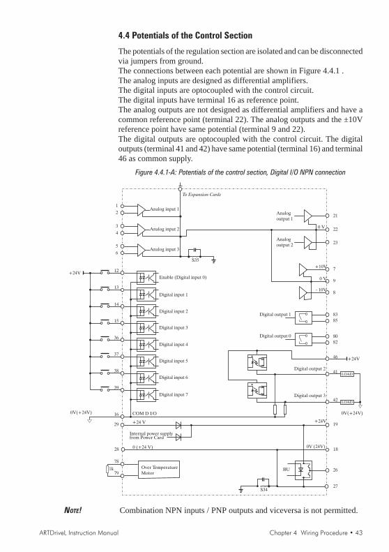
ARTDriveL Instruction Manual Chapter 4 Wiring Procedure • 43
4.4 Potentials of the Control Section
The potentials of the regulation section are isolated and can be disconnectedvia jumpers from ground.The connections between each potential are shown in Figure 4.4.1 .The analog inputs are designed as differential amplifiers.The digital inputs are optocoupled with the control circuit.The digital inputs have terminal 16 as reference point.The analog outputs are not designed as differential amplifiers and have acommon reference point (terminal 22). The analog outputs and the ±10Vreference point have same potential (terminal 9 and 22).The digital outputs are optocoupled with the control circuit. The digitaloutputs (terminal 41 and 42) have same potential (terminal 16) and terminal46 as common supply.
Figure 4.4.1-A: Potentials of the control section, Digital I/O NPN connection
1
2
3
4
5
6
+24V
13
14
15
36
37
38
39
16
29
28
Over TemperatureMotor
1k
Analog input 1
Analog input 2
Analog input 3
Enable (Digital input 0)
Digital input 1
Digital input 2
Digital input 3
Digital input 4
Digital input 5
Digital input 6
Digital input 7
Internal power supplyfrom Power Card
COM D I/O
+24 V
0 (+24 V)
78
79
Analogoutput 2
21
220 V
23
7
9
8
+10V
- 10V
0 V
8385
8082
Digital output 1
Digital output 0
46
41
42
Digital output 2
Digital output 3
19
18
26
27
+24V
0V (24V)
BU
To Expansion Cards
S35
S34
Analogoutput 1
0V(+24V)
LOAD
+24V
0V(+24V)
LOAD
12
NOTE! Combination NPN inputs / PNP outputs and viceversa is not permitted.
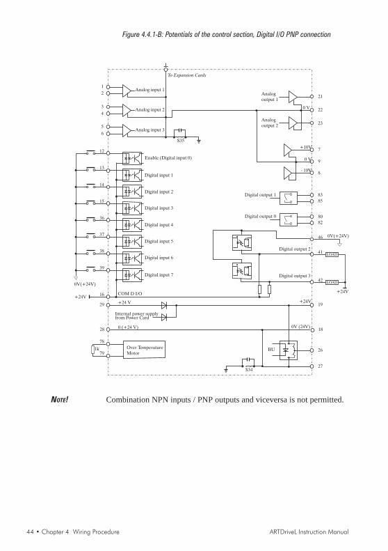
44 • Chapter 4 Wiring Procedure ARTDriveL Instruction Manual
Figure 4.4.1-B: Potentials of the control section, Digital I/O PNP connection
1
2
3
4
5
6
13
14
15
36
37
38
39
16
29
28
Over TemperatureMotor
1k
Analog input 1
Analog input 2
Analog input 3
Enable (Digital input 0)
Digital input 1
Digital input 2
Digital input 3
Digital input 4
Digital input 5
Digital input 6
Digital input 7
Internal power supplyfrom Power Card
COM D I/O
+24 V
0 (+24 V)
78
79
Analogoutput 2
21
220 V
23
7
9
8
+10V
- 10V
0 V
8385
8082
Digital output 1
Digital output 0
46
41
42
Digital output 2
Digital output 3
19
18
26
27
+24V
0V (24V)
BU
To Expansion Cards
S35
S34
Analogoutput 1
0V(+24V)
LOAD
LOAD
+24V+24V
0V(+24V)
12
NOTE! Combination NPN inputs / PNP outputs and viceversa is not permitted.

ARTDriveL Instruction Manual Chapter 4 Wiring Procedure • 45
4.5 Encoders
Several types of encoders may be connected to the XE connector (high density15-pole socket, fitted on device), see the table 4.5.2 for the jumper settings.
• AVy ... AC / AC4 :- DE: digital incremental encoder with A+/A-,B+/B-,C+/C- traces- SE: sinusoidal incremental encoder with A+/A-,B+/B-,C+/C traces
• AVy ... BR / BR4 :- SEHS: sinusoidal incremental encoder with A+/A-,B+/B-,C+/C- traces
and three digital “Hall sensor” absolute position traces for initialsynchronization (factory setting).
- SESC: sinusoidal incremental encoder with A+/A-,B+/B-,C+/C- tracesand two analog Sin Cos absolute position traces for initialsynchronization.
- SExtern: sinusoidal incremental encoder with A+/A-,B+/B-,C+/C-traces and absolute position information thought SSI serial interfacefor initial synchronization (requires APC100y card).
- DEHS: digital incremental encoder with A+/A-,B+/B-,C+/C- tracesand three digital “Hall sensor” absolute position traces (factory setting).
- DExtern: digital incremental encoder with A+/A-,B+/B-,C+/C tracesand absolute position information thought SSI serial interface for initialsynchronization (requires APC100y card).
- SC: sinusoidal encoder with two analog SinCos absolute position traces- RES: resolver (requires EXP-RES card)- SEHiperface: sinusoidal incremental encoder with A+/A-,B+/B-, traces
and Hiperface interface- SE Intern sinusoidal incremental encoder with A+/A-,B+/B-,C+/C-
traces, absolute position traces are not necessary because phasing isperformed automatically at every start
- DE Intern digital incremental encoder with A+/A-,B+/B-,C+/C- traces,absolute position traces are not necessary because phasing is performedautomatically at every start .
Encoders are used to feed back a speed signal to the drive. The encodershould be coupled to the motor shaft with a backlash free connection.Optimal regulation results are ensured when using sinusoidal encoders.Digital encoders may also be used but regulation properties get worse atlow speeds.The encoder cable must made of twisted pairs with a global shield shouldbe connected to the ground on the Drive side. Typically shield should notbe connected to ground on the motor side. In some installation with highelectromagnetical noise connecting the shield also on motor side helps tosuppress pickup of false encoder pulses and reduces amount of disturbanesin the measured speed.
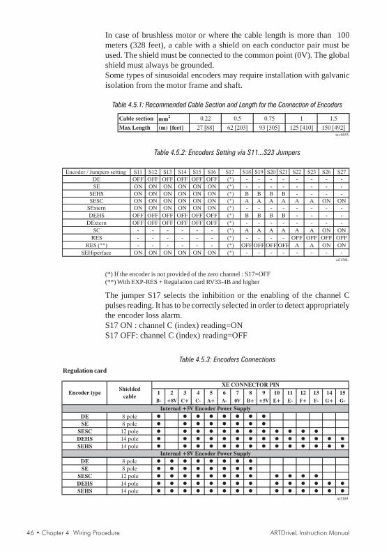
46 • Chapter 4 Wiring Procedure ARTDriveL Instruction Manual
In case of brushless motor or where the cable length is more than 100meters (328 feet), a cable with a shield on each conductor pair must beused. The shield must be connected to the common point (0V). The globalshield must always be grounded.Some types of sinusoidal encoders may require installation with galvanicisolation from the motor frame and shaft.
Table 4.5.1: Recommended Cable Section and Length for the Connection of Encoders
Cable section mm2 0.22 0.5 0.75 1 1.5
Max Length (m) [feet] 27 [88] 62 [203] 93 [305] 125 [410] 150 [492]txv0055
Table 4.5.2: Encoders Setting via S11...S23 Jumpers
Encoder / Jumpers setting S11 S12 S13 S14 S15 S16 S17 S18 S19 S20 S21 S22 S23 S26 S27
DE OFF OFF OFF OFF OFF OFF (*) - - - - - - - -
SE ON ON ON ON ON ON (*) - - - - - - - -
SEHS ON ON ON ON ON ON (*) B B B B - - - -
SESC ON ON ON ON ON ON (*) A A A A A A ON ON
SExtern ON ON ON ON ON ON (*) - - - - - - - -
DEHS OFF OFF OFF OFF OFF OFF (*) B B B B - - - -
DExtern OFF OFF OFF OFF OFF OFF (*) - - - - - - - -
SC - - - - - - (*) A A A A A A ON ON
RES - - - - - - (*) - - - - OFF OFF OFF OFF
RES (**) - - - - - - (*) OFF OFF OFF OFF A A ON ON
SEHiperface ON ON ON ON ON ON (*) - - - - - - - -
ai3150L
(*) If the encoder is not provided of the zero channel : S17=OFF(**) With EXP-RES + Regulation card RV33-4B and higher
The jumper S17 selects the inhibition or the enabling of the channel Cpulses reading. It has to be correctly selected in order to detect appropriatelythe encoder loss alarm.S17 ON : channel C (index) reading=ONS17 OFF: channel C (index) reading=OFF
Table 4.5.3: Encoders ConnectionsRegulation card
1 2 3 4 5 6 7 8 9 10 11 12 13 14 15
B- +8V C+ C- A+ A- 0V B+ +5V E+ E- F+ F- G+ G-
DE 8 pole
SE 8 pole
SESC 12 pole
DEHS 14 pole
SEHS 14 pole
DE 8 pole
SE 8 pole
SESC 12 pole
DEHS 14 pole
SEHS 14 pole
ai3160
Internal +8V Encoder Power Supply
XE CONNECTOR PIN
Encoder typeShielded
cable
Internal +5V Encoder Power Supply

ARTDriveL Instruction Manual Chapter 4 Wiring Procedure • 47
Regulation card
1 2 3 4 5 6 7 8 9 10 11 12 13 14 15
B- +8V C+ C- A+ A- 0V B+ +5V E+ E- F+ F- G+ G-
6 pole
1 2 3 4 5 6 7 8 9
RxA
TxA0V
RxB
TxB+5V
2 pole connect
with pin 8
connect
with pin 9
ai3161L
Note: - In this case the cable must be split in two
TERMINALS XS connector
Encoder typeShielded
cable
XE CONNECTOR PIN (RV33-3)
SEHiperface
Encoder / Jumpers setting S11 S12 S13 S14 S15 S16 S17 S18 S19 S20 S21 S22 S23 S26 S27
DE OFF OFF OFF OFF OFF OFF (*) - - - - - - - -
SE ON ON ON ON ON ON (*) - - - - - - - -
SEHS ON ON ON ON ON ON (*) B B B B - - - -
SESC ON ON ON ON ON ON (*) A A A A A A ON ON
SExtern ON ON ON ON ON ON (*) - - - - - - - -
DEHS OFF OFF OFF OFF OFF OFF (*) B B B B - - - -
DExtern OFF OFF OFF OFF OFF OFF (*) - - - - - - - -
SC - - - - - - (*) A A A A A A ON ON
RES - - - - - - (*) - - - - OFF OFF OFF OFF
RES (**) - - - - - - (*) OFF OFF OFF OFF A A ON ON
SEHiperface ON ON ON ON ON ON (*) - - - - - - - -
ai3150L
Requirements:
Sinusoidal encoders (XE connector on Regulation card)Max. frequency ______________ 80 kHz (select the appropriate number of pulses
depending on required max. speed )Number of pulses per revolution __ min 512, max 9999 (see table below)Channels ___________________ two-channel, differentialInput Voltage ________________ 1 V ppPower supply ________________ + 5 V / +8V (Internal supply) *Load capacity _______________ > 8.3 mA pp per channel (input resistance = 124 Ohms).Cable max. _________________ 500 feet (150 m), screened, 4 twisted pairs.
Configure drive software for the signal amplitude range of the encoder in use (STARTUP /Startup config / Encoders config / Std sin enc Vp)

48 • Chapter 4 Wiring Procedure ARTDriveL Instruction Manual
Digital encoders (XE connector on Regulation card)Type ______________________ standard and inverted signalMax. frequency ______________ 150 kHz (select the appropriate number of pulses
depending on required max. speed )Number of pulses per revolution __ min 512, max 9999 (see table below)Channels ___________________ - two-channel, differential A+ / A-, B+ / B-, C+ / C-. An encoder
loss detection is possible via firmware setting.- two channel, (A,B). Encoder loss detection is not possible.
Input Voltage ________________ 5VPower supply ________________ + 5 V / +8V (Internal supply) *Load capacity _______________ > 4.5 mA / 6.8 ... 10 mA per channel
* Via keypad (STARTUP / Startup config / Encoder config) it is possible to select 4 differentvalues of internal encoder supply voltage to compensate the voltage reduction due to encodercable length and load current encoder.Selection available, according to S28 jumper, are: 5.41V, 5.68V, 5.91V, 6.18V and 8.16V,8.62V, 9.00V, 9.46V via Std enc supply parameter.
Encoder power supply test (if the internal supply +5V is used)During the start up of the drive:- verify the encoder power supply to the encoders terminals with all the
encoders channels connected- via Std enc supply parameter set the appropriate voltage if the encoder
supply characteristic (example: +5V ± 5%) is out of range.
Terminals for external encoder connections
Male terminals type: ___________ 15 poles high density (VGA type)Connector cover: _____________ Standard 9 poles low profile (Example manufacturer code: AMP
0-748676-1, 3M 3357-6509)
1 5
6 9
1 5
11 156 10
XE XS
Speed D referenceresolution (rpm)
Max number of encoderpulses (ppr)
(FSS=Full scale speed)
0.0031250.1250.250.5
1
80kHz* 60/FSS
Mot.pole pairs (rpm@50Hz)Mot.pole pairs (rpm@60Hz)
Recommended min number of encoder pulses (ppr)
40961024512512512
2(1500)2(1500)2(1500)2(1500)2(1500)2(1800)2(1800)2(1800)2(1800)2(1800)
40961024512512512
3(1000)3(1000)3(1000)3(1000)3(1000)3(1200)3(1200)3(1200)3(1200)3(1200)
40961024102410241024
4(750)4(750)4(750)4(750)4(750)4(900)4(900)4(900)4(900)4(900)
40961024102410241024
5(600)5(600)5(600)5(600)5(600)5(720)5(720)5(720)5(720)5(720)
40961024102410241024
6(500)6(500)6(500)6(500)6(500)6(600)6(600)6(600)6(600)6(600)
40961024
512512512
1(3000)1(3000)1(3000)1(3000)1(3000)1(3600)1(3600)1(3600)1(3600)1(3600)
Speed D referenceresolution (rpm)
Max number of encoderpulses (ppr)
(FSS=Full scale speed)
0.0031250.1250.250.5
1
150kHz* 60/FSS
Mot.pole pairs (rpm@50Hz)Mot.pole pairs (rpm@60Hz)
Recommended min number of encoder pulses (ppr)
512512512512512
2(1500)2(1500)2(1500)2(1500)2(1500)2(1800)2(1800)2(1800)2(1800)2(1800)
512512512512512
3(1000)3(1000)3(1000)3(1000)3(1000)3(1200)3(1200)3(1200)3(1200)3(1200)
10241024102410241024
4(750)4(750)4(750)4(750)4(750)4(900)4(900)4(900)4(900)4(900)
10241024102410241024
5(600)5(600)5(600)5(600)5(600)5(720)5(720)5(720)5(720)5(720)
10241024102410241024
6(500)6(500)6(500)6(500)6(500)6(600)6(600)6(600)6(600)6(600)
512256256256256
1(3000)1(3000)1(3000)1(3000)1(3000)1(3600)1(3600)1(3600)1(3600)1(3600)

ARTDriveL Instruction Manual Chapter 4 Wiring Procedure • 49
The connection with the drive is through a 15 poles high density sub-Dconnector (VGA type). Please note that it is mandatory to use a shieldedcable with al least 80 % coverage. The shield should be connected to groundon both sides.
NOTE! For synchronous brushless firmware it is possible to use only encoder havingpulses per revolution equal to number that is power of 2.Example: 512 ppr, 1024 ppr, 2048 ppr, etc.
Table 4.5.4: Assignment of the High Density XE Connector for a Sinusoidal or a DigitalEncoder
Function I/O Max. voltage Max. current
Channel B- 5 V digital or 10 mA digital or
Incremental encoder signal B negative 1 V pp analog 8.3 mA analog
PIN 2 +8V Encoder supply voltage (see table 4.5.3) O +8 V 200 mA
Channel C+ 5 V digital or 10 mA digital or
Incremental encoder signal Index positive 1 V pp analog 8.3 mA analog
Channel C- 5 V digital or 10 mA digital or
Incremental encoder signal Index negative 1 V pp analog 8.3 mA analog
Channel A+ 5 V digital or 10 mA digital or
Incremental encoder signal A positive 1 V pp analog 8.3 mA analog
Channel A- 5 V digital or 10 mA digital or
Incremental encoder signal A negative 1 V pp analog 8.3 mA analog
PIN 7 GND Reference point for +5V encoder supply voltage O – –
Channel B+ 5 V digital or 10 mA digital or
Incremental encoder signal B positive 1 V pp analog 8.3 mA analog
PIN 9 AUX+ +5V encoder supply voltage (see table 4.5.3) O +5 V 200 mA
Channel HALL1 + / SIN+ 5 V digital or 10 mA digital or
Hall 1 positive / Analog encoder Sin positive 1 V pp analog 8.3 mA analog
Channel HALL 1- / SIN- 5 V digital or 10 mA digital or
Hall 1 negative / Analog encoder Sin negative 1 V pp analog 8.3 mA analog
Channel HALL 2+ / COS+ 5 V digital or 10 mA digital or
Hall 2 positive / Analog encoder Cos positive 1 V pp analog 8.3 mA analog
Channel HALL 2- / COS- 5 V digital or 10 mA digital or
Hall 2 negative / Analog encoder Cos negative 1 V pp analog 8.3 mA analog
Channel HALL 3 + 5 V digital or
Hall 3 positive 1 V pp analog
Channel HALL 3 - 5 V digital or
Hall 3 negative 1 V pp analogai3140L
I
I
PIN 6
PIN 8
ENC A-
ENC B+
PIN 10
PIN 11
I
IHALL 1-/SIN-
HALL 1+/SIN+
I
I
I
I
10 mA digital
10 mA digitalPIN 14
I
I
I
PIN 15 I
PIN 12
PIN 13
Designation
ENC B-
ENC C-
ENC A+
ENC C+
PIN 1
PIN 3
PIN 4
PIN 5
HALL 2+/COS+
HALL 2-/COS-
HALL 3+
HALL 3-
4.5.1 XFR Connector Assignments (on optional EXP-RES ExpansionBoard for Resolver)
The connection with the drive is through a 15 poles high density sub-Dconnector (VGA type). Please note that for resolver feedback it is mandatoryto use a twisted pair cable with shields on each pair and a global shield.The shield should be connected to ground on both sides.

50 • Chapter 4 Wiring Procedure ARTDriveL Instruction Manual
Function I/O Max. voltage Max.current
Pin 1 … 2 - - - - -
Pin 3 RES-SINP Input sin + I 1 V pp analog 3.8 mA analog
Pin 4 RES-SINN Input sin - I 1 V pp analog 3.8 mA analog
Pin 5 RES-COSP Input cos + I 1 V pp analog 3.8 mA analog
Pin 6 RES-COSN Input cos - I 1 V pp analog 3.8 mA analog
Pin 7 … 9 - - - - -
Pin 10 RES-ROTN Excitation - Output O 6 Volts 50 mA rms max
Pin 11 … 14 - - - - -
Pin 15 RES-ROTP Excitation + Output O 6 Volts 50 mA rms max
ai3140ER
Assignment
WARNING! The pins number 1, 2, 7...9, 11...14 are reserved.
NOTE! Refer to EXP-RES manual (code 1S5E66) for more details.
4.5.2 Encoder Simulation
The expansion board EXP-RES provides one incremental encoder output,with TTL Line Driver levels, that can be used for simulation of a servomotorfeedback device.This function is performed by the microprocessor and it is possible tosimulate an encoder output with a programmable number of pulses/rev.The output interface is optically isolated and therefore the encoder outputmust be supplied with an external 15.24 V supply that can be connected toterminals 96 and 97 of the EXP-RES expansion board.The encoder output signals are available on the XFO connector with thefollowing connection diagram:
Function
Pin 1 B- Digital Encoder Simulation. B - channel
Pin 2
Pin 3 C+ Digital Encoder Simulation.C + channel
Pin 4 C- Digital Encoder Simulation. C- channel
Pin 5 A+ Digital Encoder Simulation. A+ channel
Pin 6 A- Digital Encoder Simulation. A - channel
Pin 7
Pin 8 B+ Digital Encoder Simulation. B+ channel
Pin 9 .. 15
ai3307L
Designation
NOTE! Jumper S2 and S3 on the EXP-RES optional board must be OFF.
NOTE! To enable encoder simulation set Rep/sim encoder parameter.
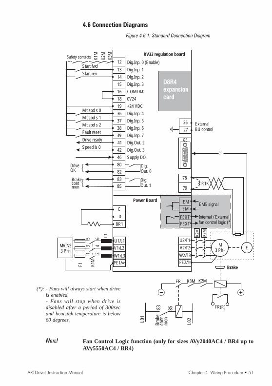
ARTDriveL Instruction Manual Chapter 4 Wiring Procedure • 51
4.6 Connection Diagrams
Figure 4.6.1: Standard Connection Diagram
12 Dig.Inp. 0 (Enable)
13 D 1ig.Inp.
14 D 2ig.Inp.
19 +24 VDC
36 D 4ig.Inp.
37 D 5ig.Inp.
38 D 6ig.Inp.
39 D 7ig.Inp.
41 D 2ig.Out.
42 D 3ig.Out.
46 Supply DO
80
82
83
85
15 D 3ig.Inp.
18 0V24
16 COM DI/0
D0
ig.Out.
D1
ig.Out.
C
D
BR1
XE
MAINS3 Ph~
U1/L1
V1/L2
W1/L3
L1
K1M
F1
24
6
13
5
EMS signal
RV33 regulation board
K1M
K2M
K3MSafety contacts
Start fwd
Start rev
Mlt spd s 0
Mlt spd s 1
Mlt spd s 2
Fault reset
Drive ready
Speed is 0
DriveOK
Brakecontmon
M3 Ph~
E
R1K
78
79
PE2/
K2M
K3M
26
27
ExternalBU control
U2/T1
V2/T2
W2/T3
PE1/
EM
EM
FEXT
FEXT
Internal / Externalfan control logic (*)
D8R4expansioncard
+-
K2MK3MFR
FR(R)83 85
L01
L02
Bra
keco
ntm
on
Power Board
Brake
15
11
15
610
NOTE! Fan Control Logic function (only for sizes AVy2040AC4 / BR4 up toAVy5550AC4 / BR4)
(*): - Fans will always start when driveis enabled.- Fans will stop when drive isdisabled after a period of 300secand heatsink temperature is below60 degrees.
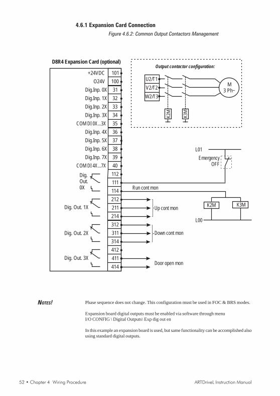
52 • Chapter 4 Wiring Procedure ARTDriveL Instruction Manual
4.6.1 Expansion Card ConnectionFigure 4.6.2: Common Output Contactors Management
414
411
412
314
311
312
D 2Xig. Out.
214
211
212
114
111
112D
0X
ig.Out.
40
39
38
37
36
COM DI 4X...7X
D 7Xig.Inp.
D 6Xig.Inp.
D 5Xig.Inp.
D 4Xig.Inp.
COM DI 0X...3X 35
34
33
32
31
D 3Xig.Inp.
D 2Xig.Inp.
D 1Xig.Inp.
D 0Xig.Inp.
O24V
+24VDC 101
100
Up cont mon
Down cont mon
K2M K3M
L00
EmergencyOFF
L01
D 1Xig. Out.
D 3Xig. Out.
D8R4 Expansion Card (optional)
Run cont mon
Door open mon
M3 Ph~
U2/T1
V2/T2
W2/T3
Output contactor configuration:
K3M
K2M
NOTES! Phase sequence does not change. This configuration must be used in FOC & BRS modes.
Expansion board digital outputs must be enabled via software through menuI/O CONFIG \ Digital Outputs\ Exp dig out en
In this example an expansion board is used, but same functionality can be accomplished alsousing standard digital outputs.
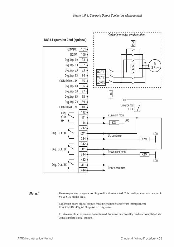
ARTDriveL Instruction Manual Chapter 4 Wiring Procedure • 53
Figure 4.6.3: Separate Output Contactors Management
414
411
412
314
311
312
D 2Xig. Out.
214
211
212
114
111
112D
0X
ig.Out.
40
39
38
37
36
COM DI 4X...7X
D 7Xig.Inp.
D 6Xig.Inp.
D 5Xig.Inp.
D 4Xig.Inp.
COM DI 0X...3X 35
34
33
32
31
D 3Xig.Inp.
D 2Xig.Inp.
D 1Xig.Inp.
D 0Xig.Inp.
O24V
+24VDC 101
100
Up cont mon
Down cont mon
L00
EmergencyOFF
L01
D 1Xig. Out.
D 3Xig. Out.
D8R4 Expansion Card (optional)
Run cont mon
Door open mon
K2M
K3M
L00
KGL00
M3 Ph~
KG
U2/T1
V2/T2
W2/T3
Output contactor configuration:
K3M
K2M
NOTES! Phase sequence changes according to direction selected. This configuration can be used inVF & SLS modes only.
Expansion board digital outputs must be enabled via software through menuI/O CONFIG \ Digital Outputs\ Exp dig out en
In this example an expansion board is used, but same functionality can be accomplished alsousing standard digital outputs.

54 • Chapter 4 Wiring Procedure ARTDriveL Instruction Manual
4.7 Circuit Protection
4.7.1 External Fuses for the Power Section
The inverter must be fused on the AC Input side. Use fast fuses only.
NOTE! Connections with three-phase inductance on AC input are not essential butwill improve the DC link capacitors lifetime.
Table 4.7.1.1: External Fuse Types for AC Input Side
Europe USA
1007
1015
1022 25000
1030 10000
2040 25000 GRD2/20 (F4D15) or Z14GR20 (F4M07) A70P20 FWP20 (S7G48)
2055 25000 GRD2/25 (F4D16) or Z14GR25 (F4M09) A70P25 FWP25 (S7G51)
2075 10000 GRD3/35 (F4D20) or Z22GR40 A70P35 FWP35 (S7G86)
3110 25000
3150 10000
4185 … 81600 10000
1007 50000
1015 50000
1022 50000 A70P10 FWP10 (S7G49)
1030 50000
2040 50000
2055 50000 GRD2/20 (F4D15) or Z14GR20 (F4M07) A70P20 FWP20 (S7G48)
2075 50000 GRD2/25 (F4D16) or Z14GR25 (F4M09) A70P25 FWP25 (S7G51)
3110 50000
3150 50000
4185 … 4221 25000
4300 25000
4301 - 4370 25000S00üf1/80/100A/660V or M00üf01/100A/660V
(F4G18)A70P100 FWP100 (S7G55)
4371 25000 S00üf1/80/125A/660V A70P150 FWP150 (S7G56)
5450 25000
5550 25000
6750 25000
7900 25000
71100 25000
71320 25000
81600 25000TADL4120
S2üf1/110/400A/660V or M2üf1/400A/660V (F4G34) A70P400 FWP400 (S7G62)
S00üf1/80/160A/660V or M00üf01/160A/660V
(F4E15)A70P175 FWP175
S00üf1/110/250A/660V or M1üf1/250A/660V
(F4G28)A70P300 FWP300 (S7G60)
(S7G57)
(S7G48)
(S7G49)
(S7G48)
(S7G49)
Connections with three-phase reactor on AC input
25000 GRD2/10 (F4D13) or Z14GR10 (F4M03)
GRD2/16 (F4D14) or Z14GR16 (F4M05) A70P20 FWP20
A70P10
GRD2/16 (F4D14) or Z14GR16 (F4M05)
A70P10 FWP10
A70P20 FWP20
GRD2/10 (F4D13) or Z14GR10 (F4M03)
Connections without three-phase reactor on AC input
For these types an external reactor is mandatory if the AC input impedence is equal or less
than 1%
Drive type
F1 - Fuses type (code)DC link
capacitors life
time [h]
Z22GR63 (F4M17) A70P60 FWP60 (S7G88)
FWP10
Z22GR63 (F4M17) A70P60 FWP60 (S7G88)
S00üf1/80/80A/660V or Z22gR80 A70P80 FWP80 (S7G54)
Fuse manufacturers: Type GRD2... (E27), GRD3... (E33), M... (blade fuses),Z14... 14 x 51 mm, Z22... 22 x 58 mm, S.... Jean Müller, EltvilleA70P... Gould ShawmutFWP... Bussmann
NOTE! The technical data of the fuses, e.g. dimensions, weights, heat dissipation,auxiliary contactors, are found in the manufacturers data sheets.

ARTDriveL Instruction Manual Chapter 4 Wiring Procedure • 55
4.7.2 External Fuses for the Power Section DC Input Side
Use the following fuses when a SR-32 Line Regen is used (see SR-32instruction book for more details).
Table 4.7.2.1: External Fuses Type for DC Input Side
Fuses type Code Fuses type Code
1007
1015
1022 Z14GR16 F4M05 A70P20 FWP20A14F S7G48
1030 Z14GR20 F4M07 A70P20-1 FWP20A14F S7G48
2040
2055
2075 Z14GR50 F4M15 A70P50 FWP50B S7G53
3110 Z22GR63 F4M17 A70P60-4 FWP60B S7I34
3150
4185 - 4220
4221 - 4300 S00üF1/80/100A/660V F4G18 A70P100 FWP100 S7G55
4301 - 4370 S00üF1/80/125A/660V F4G20 A70P150 FWP150 S7G56
4371 - 5450 S00üF1/80/160A/660V F4E15 A70P175 FWP175 S7G57
5550 S00üF1/80/200A/660V F4G23 A70P200 FWP200 S7G58
6750 S1üF1/110/250A/660V F4G28 A70P250 FWP250 S7G59
7900 S1üF1/110/315A/660V F4G30 A70P350 FWP350 S7G61
71100 S1üF1/110/400A/660V F4G34 A70P400 FWP400 S7G62
71320 S1üF1/110/500A/660V F4E30 A70P500 FWP500 S7G63
81600 S1üF1/110/500A/660V F4E30 A70P500 FWP500 S7G63TAVy4140
USA
A70P10 FWP10A14F S7G49Z14GR10 F4M03
Drive typeEurope
S7G51
S00üF1/80/80A/660V F4M19 A70P80 FWP80 S7G54
Z14GR32 F4M11 A70P25-1 FWP25A14F
Fuse manufacturers: Type Z14..., Z22, S00 ..., S1... Jean Müller, EltvilleA70P... Gould ShawmutFWP... Bussmann
NOTE! The technical data of the fuses, e.g. dimensions, weights, heat dissipation,auxiliary contactors, are found in the manufacturers data sheets.
4.7.3 Internal FusesTable 4.7.3.1: Internal Fuses
Drive type Designation Protection of Fuse (source) Fitted on:
Power card PV33-4-
"D" and higher
Power card PV33-5-
"B" and higher
F1 +24V Resettable fuseRegulation card
RV33
F2
RS485 serial
interface
supply circuit
Resettable fuseRegulation card
RV33-4 and higher
6750 to
71320F3
Fans
transformer
2.5A 6.3x32
(Bussmann: MDL 2.5, Gould
Shawmut: GDL1-1/2, Siba: 70 059
76.2,5 , Schurter: 0034.5233)
Bottom cover (power
terminals side)
tadl0170
1007 to
81600
2A fast 5 x 20 mm (Bussmann:
SF523220 or Schurter:
FSF0034.1519
or Littlefuse: 217002)
4185 to
81600F1 +24V
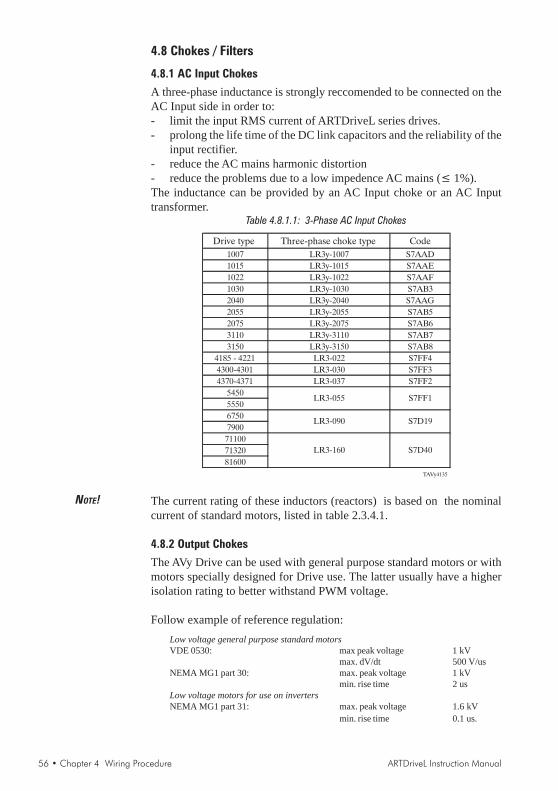
56 • Chapter 4 Wiring Procedure ARTDriveL Instruction Manual
4.8 Chokes / Filters
4.8.1 AC Input Chokes
A three-phase inductance is strongly reccomended to be connected on theAC Input side in order to:- limit the input RMS current of ARTDriveL series drives.- prolong the life time of the DC link capacitors and the reliability of the
input rectifier.- reduce the AC mains harmonic distortion- reduce the problems due to a low impedence AC mains (≤ 1%).The inductance can be provided by an AC Input choke or an AC Inputtransformer.
Table 4.8.1.1: 3-Phase AC Input Chokes
Drive type Three-phase choke type Code
1007 LR3y-1007 S7AAD
1015 LR3y-1015 S7AAE
1022 LR3y-1022 S7AAF
1030 LR3y-1030 S7AB3
2040 LR3y-2040 S7AAG
2055 LR3y-2055 S7AB5
2075 LR3y-2075 S7AB6
3110 LR3y-3110 S7AB7
3150 LR3y-3150 S7AB8
4185 - 4221 LR3-022 S7FF4
4300-4301 LR3-030 S7FF3
4370-4371 LR3-037 S7FF2
5450
5550
6750
7900
71100
71320
81600
TAVy4135
LR3-055
LR3-090
LR3-160
S7FF1
S7D19
S7D40
NOTE! The current rating of these inductors (reactors) is based on the nominalcurrent of standard motors, listed in table 2.3.4.1.
4.8.2 Output Chokes
The AVy Drive can be used with general purpose standard motors or withmotors specially designed for Drive use. The latter usually have a higherisolation rating to better withstand PWM voltage.
Follow example of reference regulation:Low voltage general purpose standard motorsVDE 0530: max peak voltage 1 kV
max. dV/dt 500 V/usNEMA MG1 part 30: max. peak voltage 1 kV
min. rise time 2 usLow voltage motors for use on invertersNEMA MG1 part 31: max. peak voltage 1.6 kV
min. rise time 0.1 us.

ARTDriveL Instruction Manual Chapter 4 Wiring Procedure • 57
Motors designed for use with Adjustable Frequency Drives do not requireany specific filtering of the voltage waveform from the Drive. For generalpurpose motors and using drives up to 2075 size, especially with longcable runs (typically over 100 m [328 feet]) an output choke isrecommended to mantain the voltage waveform within the specified limits.Suggested choke ratings and part numbers are listed in table 5.7.2.1.The rated current of the filters should be approx. 20% above the ratedcurrent of the frequency Drive in order to take into account additionallosses due to PWM waveform.
Table 4.8.2.1: Recommended Output Chokes
Drive type Three-phase choke type Code
1007
1015
1022
1030
2040
2055
2075
3110
3150 LU3-015 S7FM2
4185 - 4221 LU3-022 S7FH3
4300 - 4301 LU3-030 S7FH4
4370 - 4371 LU3-037 S7FH5
5450
5550
6750
7900
71100
71320
81600TAVy4150
LU3-011
S7FG2
S7FG3
S7FG4
LU3-003
LU3-005
LU3-055
LU3-090
LU3-160
S7FH6
S7FH7
S7FH8
NOTE! When the drive is operated at the rated current and at 50 Hz, the outputchokes cause a voltage drop of approx. 2% of the output voltage.
4.8.3 Interference Suppression Filters
The inverters of AVy series must be equipped with an external EMI filter inorder to reduce the radiofrequency emissions on to the mains line. Thefilter selection is depending on the drive size and the installationenvironment. For this purpose see the “EMC Guidelines” instruction book.In the Guide it is also indicated how to install the cabinet (connection offilter and mains reactors, cable shield, groundig, etc.) in order to make itEMC compliant according the EMC Directive 89/336/EEC. The documentdescribes the present situation concerning the EMC standards and thecompliance tests made on the Gefran-Siei drives.
NOTE! For the use of output sinusoidal filters, please contact the factory.

58 • Chapter 4 Wiring Procedure ARTDriveL Instruction Manual
4.9. Braking Units
In oversynchronous or regenerative operation, the frequency-controlledthree-phase motor feeds energy back to the DC link circuit via the drive.This creates an increase in the intermediate circuit voltage.Braking units (BU) are therefore used in order to prevent the DC voltagerising to an impermissible value. When used, these activate a braking resistorthat is connected in parallel to the capacitors of the intermediate circuit. Thefeedback energy is converted to heat via the braking resistor (RBR), thusproviding very short deceleration times and restricted four-quadrant operation.
Figure 4.9.1: Operation with Braking Unit (Principle)
E
3M
_R
BR
BU
UZK
Drive sizes 1007 up to 3150 have, as standard configuration, an internalbraking unit. Drive sizes 4220 up to 5550 can have an optional internalbraking unit (see section 2.1.2 “Inverter type designation”) factory mounted.All the standard AVy... drive can be equipped with an external braking unit(BU-32... or BUy-...) connected to the terminals C and D.
NOTE! When the internal braking unit is present, or when circuit terminals C and Dare connected to external devices, the AC Input must be protected withsuperfast semiconductor fuses! Observe the mounting instruction concerned.For braking resistor connection (terminals BR1 and C) a twisted cable hasto be used. In case the braking resistor is supplied with thermal protection(klixon), it may be connected to the "External fault" drive input.
The braking resistors can be subject to unforeseen overloads due to possiblefailures. The resistors have to be protected using thermal protection devices.Such devices do not have to interrupt the circuit where the resistor is insertedbut their auxiliary contact must interrupt the power supply of the drivepower section.In case the resistor foresees the precence of a protection contact, such contact hasto be used together with the one belonging to the thermal protection device.
4.9.1 Internal Braking UnitThe Internal Braking Unit is included as standard (up to size 3150). Thebraking resistor is optional and has always to be mounted externally. Forparameter setting refer to parameter list. The figure below shows theconfiguration for internal brake unit operation.
Figure 4.9.1.1: Connection with Internal Braking Unit and External Braking Resistor
Brakingresistor
3Ph~
PE
1/
U1
/L1
V1
/L2
W1
/L3
BR
1
U2
/T1
V2
/T2
W2
/T3
C D
PE
2/
F1
BrakingUnit
AC Motor
Warning

ARTDriveL Instruction Manual Chapter 4 Wiring Procedure • 59
4.9.2 External Braking Resistor
Recommended resistors for use with internal braking unit:
Table 4.9.2.1: Lists and Technical Data of the External Standard Resistors
Inverter Resistor PNBR RBR EBR
Type Type [kW] [Ohm] [kJ]
1007 MRI/T600 100R 0.6 100 22
1015
1022
1030
2040
2055
2075
3110 MRI/T1300 49R 1.3 49 48
3150 MRI/T2200 28R 2.2 28 82
4185 - 4221 MRI/T4000 15R4 4 15.4 150
4300 - 4301 MRI/T4000 11R6 4 11.6 150
4370 - 4371 MRI/T4000 11R6 4 11.6 150
5450 MRI/T8000 7R7 8 7.7 220
5550 MRI/T8000 7R7 8 7.7 220
TADL0250
MRI/T900 68R 0.9 68 33
Parameters description:
PNBR Nominal power of the braking resistorRBR Braking resistor valueEBR Max surge energy which can be dissipated by the resistorPPBR Peak power applied to the braking resistorTBRL Maximum braking time in condition of limit operating cycle
(braking power = PPBR with typical triangular profile)
T = 2BRL
EBR
PPBR
=[s]
Figure 4.9.2.2: Limit Operating Braking Cycle with Typical Triangular Power Profile
TCL
n,P
PPBR
TBRL
n
EBR
t
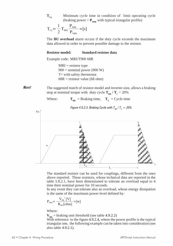
60 • Chapter 4 Wiring Procedure ARTDriveL Instruction Manual
TCL Minimum cycle time in condition of limit operating cycle(braking power = PPBR with typical triangular profile)
T =CL TBRL
PPBR
PNBR
=[s]1
2
The BU overload alarm occurs if the duty cycle exceeds the maximumdata allowed in order to prevent possible damage to the resistor.
Resistor model: Standard resistor data
Example code: MRI/T900 68R
MRI = resistor type900 = nominal power (900 W)T= with safety thermostat68R = resistor value (68 ohm)
NOTE! The suggested match of resistor-model and inverter-size, allows a brakingstop at nominal torque with duty cycle TBR / TC = 20%
Where: TBR = Braking time, TC = Cycle time
Figure 4.9.2.3: Braking Cycle with TBR / TC = 20%
TC
P,n
TBR
n
t
The standard resistor can be used for couplings, different from the onesabove reported. These resistors, whose technical data are reported in thetable 5.8.2.1, have been dimensioned to tolerate an overload equal to 4time their nominal power for 10 seconds.In any event they can tolerate also an overload, whose energy dissipationis the same of the maximum power level defined by:
P =PBR
V [V]BR
2
R [ohm]BR
=[w]
Where:VBR = braking unit threshold (see table 4.9.2.2)With reference to the figure 4.9.2.4, where the power profile is the typicaltriangular one, the following example can be taken into consideration (seealso table 4.9.2.1).

ARTDriveL Instruction Manual Chapter 4 Wiring Procedure • 61
Resistor model: MRI/T600 100R
Nominal power PNBR = 600 [W]Maximum energy EBR = 4 x 600[W] x 10[s] = 24000[J]Inverter mains supply = 460VVoltage threshold: VBR =780V
TBRL = 2EBR
PPBR
=24000
6084= 7.8[s]2PPBR =
VBR
RBR
2
=780
100
2
= 6084 [W]
It is necessary to consider the following relation:
A) If TBR ≤≤≤≤≤ EBR / PNBR verify:
1) PMB ≤≤≤≤≤ 2 * EBR / TBR Where: PMB is the average power of thecycle (see.fig. 4.9.2.4)
2)P .MB TBR
2 TC
PNBR
The average power of the cycle must not be higher than thenominal power of the resistor.
B) If TBR >>>>> EBR / PNBR that is to say, in case of very long brakingtime, it must be dimensioned PMB ≤ ≤ ≤ ≤ ≤ PNBR
Figure 4.9.2.4: Generic Braking Cycle with Triangular Profile
TC
n,P
PPBR
TBR t
PMB
If one of the above mentioned rules is not respected, it is necessary toincrease the tested power of the resistor, respecting the limit of the internalbraking unit (reported intable 4.9.2.3), or an external BU if necessary.In order to protect these resistors from dangerous overload, softwareoverload control logic is also available (STARTUP / Startup config / BUprotection).The default parameters in the drive match the recomended resistor paringas for the table 4.9.2.1.For no-standard paring resistor see “STARTUP / Startup config / BUprotection.

62 • Chapter 4 Wiring Procedure ARTDriveL Instruction Manual
Table 4.9.2.2: Braking Thresholds for Different Mains
Mains voltageBraking threshold
VBR [V]
230Vac 400
400Vac 680
460Vac/480Vac 780
avy4200
When the duty cycle exceeds the data entered, the alarm BU overloadautomatically occurs in order to prevent possible damages to the resistor.The following table can be used to choose an external resistor, differentfrom the standard series.
Table 4.9.2.3: Technical Data of the Internal Braking Units
Inverter Minimum
type IRMS IPK T RBR
[A] [A] [s] [ohm]
1007
1015
1022
1030
2040
2055
2075
3110 12 22 17 36
3150 17 31 16 26
4185 … 4221 18 52 42 15
4300 - 4301 37 23
4370 - 4371 29 37
5450
5550
6750
7900
71100
71320
81600
Tavy4210
External braking unit (optional)
1078
50 104 22 7.5
67
4.1
6.6
7.8
12
19
16
100
IRMS Nominal current of the braking unitIPK Peak current deliverable for 60 seconds max.T Minimum cycle time for a working at IPK for 10 seconds
Generally the following condition must be satisfed
IRMS1 P TPBR BR
TRBR C2. .
Each drive is provided of the terminals 26 and 27 which allows control ofone or more external braking units, parallel connected. The drive will actas Master and the external braking units BU32 must be configured as Slave.In this way it will be possible to utilize the internal I2 t protection.If more than one BU is used, each BU shall be connected to a single resistor.All Braking Unit shall be the same model and have same type resistor.
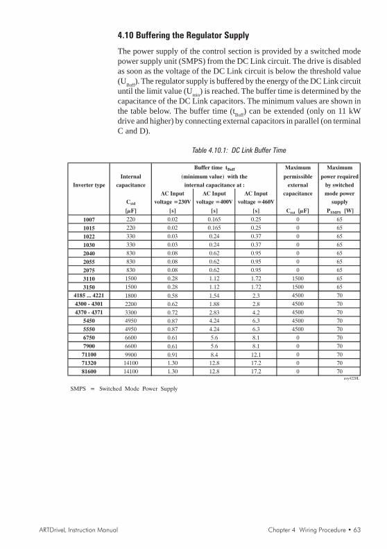
ARTDriveL Instruction Manual Chapter 4 Wiring Procedure • 63
4.10 Buffering the Regulator Supply
The power supply of the control section is provided by a switched modepower supply unit (SMPS) from the DC Link circuit. The drive is disabledas soon as the voltage of the DC Link circuit is below the threshold value(UBuff). The regulator supply is buffered by the energy of the DC Link circuituntil the limit value (Umin) is reached. The buffer time is determined by thecapacitance of the DC Link capacitors. The minimum values are shown inthe table below. The buffer time (tBuff) can be extended (only on 11 kWdrive and higher) by connecting external capacitors in parallel (on terminalC and D).
Table 4.10.1: DC Link Buffer Time
Buffer time tBuff Maximum Maximum
Internal (minimum value) with the permissible power required
Inverter type capacitance internal capacitance at : external by switched
AC Input AC Input AC Input capacitance mode power
Cstd voltage =230V voltage =400V voltage =460V supply
[µF] [s] [s] [s] Cext [µF] PSMPS [W]
1007 220 0.02 0.165 0.25 0 65
1015 220 0.02 0.165 0.25 0 65
1022 330 0.03 0.24 0.37 0 65
1030 330 0.03 0.24 0.37 0 65
2040 830 0.08 0.62 0.95 0 65
2055 830 0.08 0.62 0.95 0 65
2075 830 0.08 0.62 0.95 0 65
3110 1500 0.28 1.12 1.72 1500 65
3150 1500 0.28 1.12 1.72 1500 65
4185 ... 4221 1800 0.58 1.54 2.3 4500 70
4300 - 4301 2200 0.62 1.88 2.8 4500 70
4370 - 4371 3300 0.72 2.83 4.2 4500 70
5450 4950 0.87 4.24 6.3 4500 70
5550 4950 0.87 4.24 6.3 4500 70
6750 6600 0.61 5.6 8.1 0 70
7900 6600 0.61 5.6 8.1 0 70
71100 9900 0.91 8.4 12.1 0 70
71320 14100 1.30 12.8 17.2 0 70
81600 14100 1.30 12.8 17.2 0 70avy4220L
SMPS = Switched Mode Power Supply
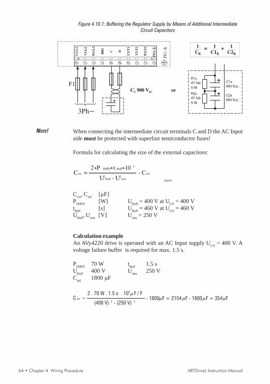
64 • Chapter 4 Wiring Procedure ARTDriveL Instruction Manual
Figure 4.10.1: Buffering the Regulator Supply by Means of Additional IntermediateCircuit Capacitors
3Ph~
PE
1/
U1/L
1
V1
/L2
W1/L
3
BR
1
U2
/T1
V2
/T2
W2/T
3
C D
PE
2/
F1
1
Cx
1
C1x
1
C2x= +
C 900 V orX DC
NOTE! When connecting the intermediate circuit terminals C and D the AC Inputside must be protected with superfast semiconductor fuses!
Formula for calculating the size of the external capacitors:
fA018
Cext =2 P SMPS t Buff 10 6
U2Buff - U2
min
- Cstd
Cext, Cstd [μF]PSMPS [W] UBuff = 400 V at ULN = 400 VtBuff [s] UBuff = 460 V at ULN = 460 VUBuff, Umin [V] Umin = 250 V
Calculation exampleAn AVy4220 drive is operated with an AC Input supply ULN = 400 V. Avoltage failure buffer is required for max. 1.5 s.
PSMPS 70 W tBuff 1.5 sUBuff 400 V Umin 250 VCstd 1800 μF
C ext =
(400 V) 2 - (250 V) 2- 1800F = 2154 F - 1800 F = 354F
2 . 70 W . 1.5 s . 10 F / F6
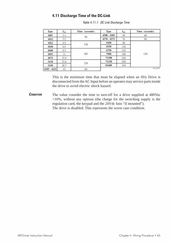
ARTDriveL Instruction Manual Chapter 4 Wiring Procedure • 65
4.11 Discharge Time of the DC-Link
Table 4.11.1: DC Link Discharge Time
Type I2N Time (seconds) Type I2N Time (seconds)
1007 2.1 4300 - 4301 58 60
1015 3.5 4370 - 4371 76 90
1022 4.9 5450 90
1030 6.5 5550 110
2040 8.3 6750 142
2055 11 7900 180
2075 15.4 71100 210
3110 21.6 71320 250
3150 28.7 81600 310
4185 - 4221 42 60 Tavy4250
120
90
150
205
220
This is the minimum time that must be elapsed when an AVy Drive isdisconnected from the AC Input before an operator may service parts insidethe drive to avoid electric shock hazard.
CONDITION The value consider the time to turn-off for a drive supplied at 480Vac+10%, without any options (the charge for the switching supply is theregulation card, the keypad and the 24Vdc fans “if mounted”).The drive is disabled. This represents the worst case condition.

66 • Chapter 4 Wiring Procedure ARTDriveL Instruction Manual
NOTE:
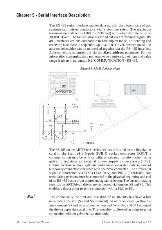
ARTDriveL Instruction Manual Chapter 5 Serial Inreface Description • 67
Chapter 5 - Serial Interface Description
The RS 485 serial interface enables data transfer via a loop made of twosymmetrical, twisted conductors with a common shield. The maximumtransmission distance is 1200 m (3936 feet) with a transfer rate of up to38,400 KBaud. The transmission is carried out via a differential signal. RS485 interfaces are bus-compatible in half-duplex mode, i.e. sending andreceiving take place in sequence. Up to 31 ARTDriveL devices (up to 128address selectable) can be networked together via the RS 485 interface.Address setting is carried out via the Slave address parameter. Furtherinformation concerning the parameters to be transfered, their type and valuerange is given in paragraph 9.2, COMMUNICATION \ RS 485.
Figure 5.1: RS485 Serial Interface
12345
9 8 7 6
150 R
TxA/RxATxB/RxB
0 V S
+5 V S
S5 S6
PE
RS485
XS
100
R
470
R
470
R
+5 V
S41
S40
The RS 485 on the ARTDriveL series devices is located on the Regulationcard in the form of a 9-pole SUB-D socket connector (XS).Thecommunication may be with or without galvanic isolation: when usinggalvanic isolation an external power supply is necessary (+5V).Communication without galvanic isolation is suggested only in case oftemporary connections for setup with one drive connected. The differentialsignal is transferred via PIN 3 (TxA/RxA) and PIN 7 (TxB/RxB). Busterminating resistors must be connected at the physical beginning and endof an RS 485 bus in order to prevent signal reflection. The bus terminatingresistors on ARTDriveL drives are connected via jumpers S5 and S6. Thisenables a direct point-to-point connection with a PLC or PC.
NOTE! Ensure that only the first and last drop of an RS 485 bus have a busterminating resistor (S5 and S6 mounted). In all other cases (within theline) jumpers S5 and S6 must not be mounted. With S40 and S41 mountedthe drive supply the serial line. This modality is allowed on point-to-pointconnection without galvanic isolation only.

68 • Chapter 5 Serial Interface Description ARTDriveL Instruction Manual
NOTE! A connection point to point can be done using “PCI-485” option interface(S40 and S41 mounted).For multidrop connection (two or more drive), an external power supply isnecessary (pin 5 / 0V and pin 9 / +5V).Pins 6 and 8 are reserved for use with the “PCI-485” interface card.
When connecting the serial interface ensure that:- only shielded cables are used- power cables and control cables for contactors/relays are routed
separately
The communication protocol can be chosen between Slink4, Modbus,Jbus, ISO 1745 or Hiperface through “Protocol type” parameter(COMMUNICATION / RS 485 / Protocol type).
5.1 RS 485 Serial Interface Connector Description
Table 5.1.1: Assignment of the Plug XS Connector for the RS 485 Serial Interface
Designation Function I/O Elec. Interface
PIN 1 Internal use – –
PIN 2 Internal use – –
PIN 3 RxA/TxA I/O RS485
PIN 4 Internal use – –
PIN 5 0V (Ground for 5 V) – Power supply
PIN 6 Internal use – –
PIN 7 RxB/TxB I/O RS 485
PIN 8 Internal use – –
PIN 9 +5 V – Power supplyai4110
I = Input O = Output

ARTDriveL Instruction Manual Chapter 6 Keypad Operation • 69
Chapter 6 - Keypad OperationThe keypad is made of a LCD display with two 16-digit lines, seven LEDsand nine function keys. It is used:- to start and stop the drive (this function can be disabled)- to display the speed, voltage, diagnostics etc. during the operation- to set parameters and enter commandsThe LED module is made of 6 LEDs. It is used to display status anddiagnostic information during the operation. Keypad and LED module canbe installed or removed also while the drive is running.
-Torque +Torque Alarm Enable ZeroSpeed Limit
-Torque Negative torque current
+Torque Positive
Alarm Alarm condition
Enable Drive enable status
ZeroSpeed Speed <=zero speed threshold
Limit Actual current >=current limit
torque current
This monitoring module can be upgraded with the keypad with
alphanumeric LCD display
NOTE! a replacement keypad cable longer than 20 cm must be shielded.
6.1 LEDs & Keys
The LEDs present on the keypad are used to quickly diagnose the operatingstate of the drive.
Designation Color Function
-Torque yellow the LED is lit when the drive operates with a negative torque
+Torque yellow the LED is lit when the drive operates with a positive torque
ALARM red the LED is lit when the drive signals a trip
ENABLE green the LED is lit when the drive is enabled
Zero speed yellow the LED is lit when motor speed is zero
Limit yellow the LED is lit when the drive operates at a current limit
Shift yellow the LED is lit when the keypad second functions are enabledts030g
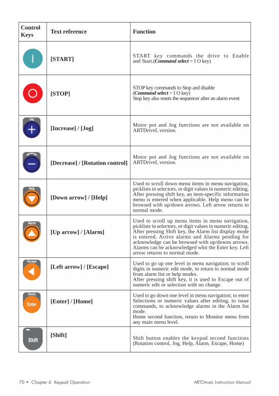
70 • Chapter 6 Keypad Operation ARTDriveL Instruction Manual
ControlKeys
Jog
Help
Alarm
Escape
Home
Enter
Shift
Text reference
[START]
[STOP]
[Increase] / [Jog]
[Decrease] / [Rotation control]
[Down arrow] / [Help]
[Up arrow] / [Alarm]
[Left arrow] / [Escape]
[Enter] / [Home]
[Shift]
Function
START key commands the drive to Enableand Start.(Command select = I O key)
STOP key commands to Stop and disable(Command select = I O key)Stop key also resets the sequencer after an alarm event
Motor pot and Jog functions are not available onARTDriveL version.
Motor pot and Jog functions are not available onARTDriveL version.
Used to scroll down menu items in menu navigation,picklists in selectors, or digit values in numeric editing.After pressing shift key, an item-specific informationmenu is entered when applicable. Help menu can bebrowsed with up/down arrows. Left arrow returns tonormal mode.
Used to scroll up menu items in menu navigation,picklists in selectors, or digit values in numeric editing.After pressing Shift key, the Alarm list display modeis entered. Active alarms and Alarms pending foracknowledge can be browsed with up/downs arrows.Alarms can be acknowledged whit the Enter key. Leftarrow returns to normal mode.
Used to go up one level in menu navigation; to scrolldigits in numeric edit mode, to return to normal modefrom alarm list or help modes.After pressing shift key, it is used to Escape out ofnumeric edit or selection with no change.
Used to go down one level in menu navigation; to enterSelections or numeric values after editing, to issuecommands, to acknowledge alarms in the Alarm listmode.Home second function, return to Monitor menu fromany main menu level.
Shift button enables the keypad second functions(Rotation control, Jog, Help, Alarm, Escape, Home)

ARTDriveL Instruction Manual Chapter 6 Keypad Operation • 71
6.2 Moving Inside a Menu
. . . . . . . . . . . ... . . . . . . . . . . . . . .
MAIN MENU
R: S:
MONITOR
STARTUP
TRAVEL
SERVICE
OUTPUT VOLT AGE
340V
STARTUP
Regulation mode
Startup config
STARTUP
Save config?
Busy
Please wait
Enter to MONITOR menu
Escape from MONITORScroll
down
Scroll
up
Enter to
STARTUP menu
Escape from
STARTUP
Enter forSAVE PARAMETERS
Escape from
STARTUP
R: S:
R: S:
R: S:
STARTUP
6.3 Using Keypad Help
R: S:MONITOR
STARTUP
Output voltage
0 V
Output current
0.00A
SHIFT + HELP
Help max value
0.000
Help min value
Help mode ZUSWR
---11
R: S:0.000

72 • Chapter 6 Keypad Operation ARTDriveL Instruction Manual
6.4 Drive Main Menu
R: S :
MONITOR
R: S :
STARTUP
R: S :
TRAVEL
R: S :
REGULATION PARAM
R: S :
I/O CONFIG
R: S :
ALARM CONFIG
R: S :
COMMUNICATION
R: S :
APPL CARD CONFIG
R: S :
CUSTOM FUNCTIONS
R: S :
SERVICE
PasswordLEVEL 1
PasswordLEVEL 2
* SERVICE menu allows the setting of the password to enable Level 1 drive menus: 12345.To have the access of Level 1 drive menus, edit 12345 password into “Insert Password”parameter and confirm it using “Enter” button.
NOTE! Level 1 password must be set every recycle drive supply
Drive status variables
Drive & Motor initial setup,Lift mechanical data
Lift parameters
Regulator gain & controlparameters
Input / Output & commandsconfigurations
Alarm configurations
Serial link, communication card
Application card configurations
Signal compare blocksProgrammable block area & PADconfigurations
Service purpose menu withpassword *

ARTDriveL Instruction Manual Chapter 7 Commissioning • 73
Select theRegulation mode
Set Drive data
Set Motor data
Run motor Autotune
Set all systemmechanical data
Encoder typeconfiguration
Drive comes factory defaulted to V/f control, change toField Oriented vector control.
Go to Setup mode for drive data parametrization:Mains voltage, Ambient temp, Switching freq, Speedreference resolution
Go to Setup mode for motor data parametrization:Rated voltage, Rated frequency, Rated current, Ratedspeed, Rated power, Cosphi
Autotune procedure is a real motor parametersmeasurement; two options are available:- “Complete still” can be used when motor is coupled togearbox, brake is applied and lift car is installed. It couldcause limited shaft rotation when brake is not applied.- “Complete rot” can be used when motor is uncoupledor gearbox does not represent more than 5% load and liftcar is not installed. It causes motor shaft rotation closeto the rated speed.
System mechanical data:Gearbox ratio, Pulley diameter, Full scale speed.
- 6.1 : Feedback from encoder connected to XEconnector on Regulation card- 6.2 : Feedback from encoder connected to XFIconnector on EXP-... optional card
Step
Chapter 7 - Commissioning via KeypadThe ARTDrive Lift can operate with advanced Voltage /Frequency control(as default), Sensorless vector control (open-loop), Field Oriented vectorcontrol (closed-loop) and Brushless.All the regulation modes have their own-independent parameter sets.A commissioning executed in one mode should be repeated or transferredto another regulation mode.
7.1 Commissioning for AVy...AC / AC4 (Asychronous Motors)
Commissioning Set-up Procedure
1
2
3
4
6.1
6.2
5
Closed-loop - Field Oriented mode (see chapter 7.1.1)
Function Description
Go to step 6 up to step 9 of chapter 7.1.3
or
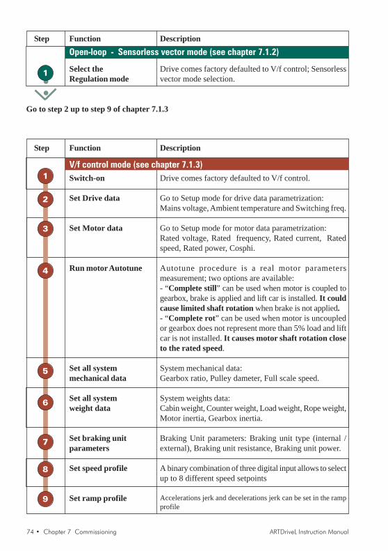
74 • Chapter 7 Commissioning ARTDriveL Instruction Manual
Function DescriptionStep
Drive comes factory defaulted to V/f control; Sensorlessvector mode selection.
Select theRegulation mode
Open-loop - Sensorless vector mode (see chapter 7.1.2)
1
Go to step 2 up to step 9 of chapter 7.1.3
Function DescriptionStep
Drive comes factory defaulted to V/f control.
Go to Setup mode for drive data parametrization:Mains voltage, Ambient temperature and Switching freq.
Go to Setup mode for motor data parametrization:Rated voltage, Rated frequency, Rated current, Ratedspeed, Rated power, Cosphi.
Autotune procedure is a real motor parametersmeasurement; two options are available:- “Complete still” can be used when motor is coupled togearbox, brake is applied and lift car is installed. It couldcause limited shaft rotation when brake is not applied.- “Complete rot” can be used when motor is uncoupledor gearbox does not represent more than 5% load and liftcar is not installed. It causes motor shaft rotation closeto the rated speed.
System mechanical data:Gearbox ratio, Pulley dameter, Full scale speed.
System weights data:Cabin weight, Counter weight, Load weight, Rope weight,Motor inertia, Gearbox inertia.
Braking Unit parameters: Braking unit type (internal /external), Braking unit resistance, Braking unit power.
A binary combination of three digital input allows to selectup to 8 different speed setpoints
Accelerations jerk and decelerations jerk can be set in the rampprofile
Switch-on
Set Drive data
Set Motor data
Run motor Autotune
Set all systemmechanical data
Set all systemweight data
Set braking unitparameters
Set speed profile
Set ramp profile
V/f control mode (see chapter 7.1.3)1
2
3
4
5
6
7
8
9
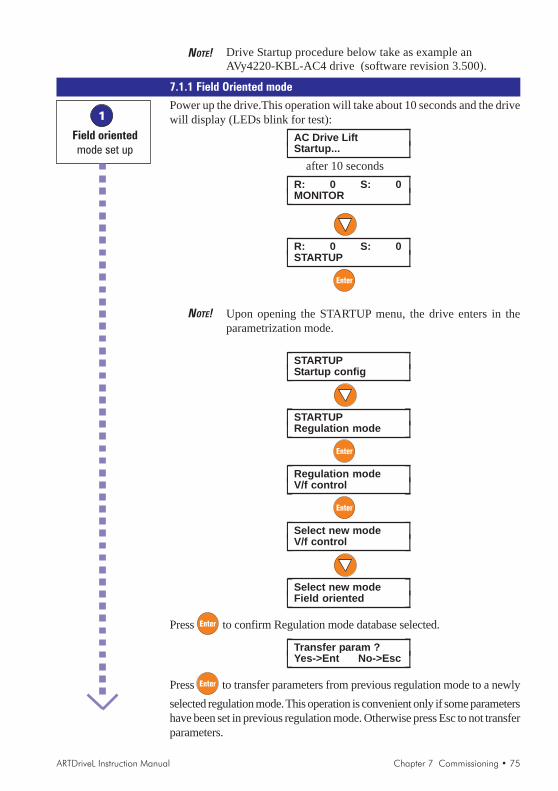
ARTDriveL Instruction Manual Chapter 7 Commissioning • 75
NOTE! Drive Startup procedure below take as example anAVy4220-KBL-AC4 drive (software revision 3.500).
7.1.1 Field Oriented mode
Power up the drive.This operation will take about 10 seconds and the drivewill display (LEDs blink for test):
⎡ ⎤AC Drive LiftStartup...⎣ ⎦
after 10 seconds⎡ ⎤R: 0 S: 0
MONITOR⎣ ⎦
⎡ ⎤R: 0 S: 0STARTUP⎣ ⎦
NOTE! Upon opening the STARTUP menu, the drive enters in theparametrization mode.
⎡ ⎤STARTUPStartup config⎣ ⎦
⎡ ⎤STARTUPRegulation mode⎣ ⎦
⎡ ⎤Regulation modeV/f control⎣ ⎦
⎡ ⎤Select new modeV/f control⎣ ⎦
⎡ ⎤Select new modeField oriented⎣ ⎦
Press to confirm Regulation mode database selected.
⎡ ⎤Transfer param ?Yes->Ent No->Esc⎣ ⎦
Press to transfer parameters from previous regulation mode to a newlyselected regulation mode. This operation is convenient only if some parametershave been set in previous regulation mode. Otherwise press Esc to not transferparameters.
1
Field orientedmode set up
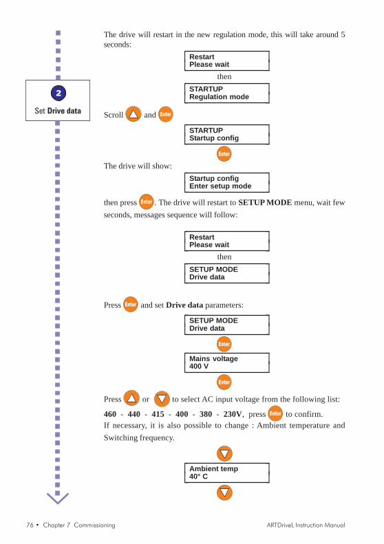
76 • Chapter 7 Commissioning ARTDriveL Instruction Manual
The drive will restart in the new regulation mode, this will take around 5seconds:
⎡ ⎤RestartPlease wait⎣ ⎦
then⎡ ⎤STARTUP
Regulation mode⎣ ⎦
Scroll and
⎡ ⎤STARTUPStartup config⎣ ⎦
The drive will show:⎡ ⎤Startup config
Enter setup mode⎣ ⎦
then press . The drive will restart to SETUP MODE menu, wait fewseconds, messages sequence will follow:
⎡ ⎤RestartPlease wait⎣ ⎦
then⎡ ⎤SETUP MODE
Drive data⎣ ⎦
Press and set Drive data parameters:
⎡ ⎤SETUP MODEDrive data⎣ ⎦
⎡ ⎤Mains voltage400 V⎣ ⎦
Press or to select AC input voltage from the following list:
460 - 440 - 415 - 400 - 380 - 230V, press to confirm.If necessary, it is also possible to change : Ambient temperature andSwitching frequency.
⎡ ⎤Ambient temp40° C⎣ ⎦
2
Set Drive data
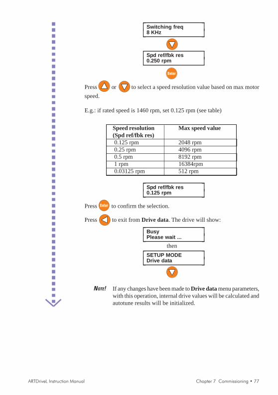
ARTDriveL Instruction Manual Chapter 7 Commissioning • 77
⎡ ⎤Switching freq8 KHz⎣ ⎦
⎡ ⎤Spd ref/fbk res0.250 rpm⎣ ⎦
Press or to select a speed resolution value based on max motorspeed.
E.g.: if rated speed is 1460 rpm, set 0.125 rpm (see table)
Speed resolution Max speed value(Spd ref/fbk res) 0.125 rpm 2048 rpm 0.25 rpm 4096 rpm 0.5 rpm 8192 rpm 1 rpm 16384rpm 0.03125 rpm 512 rpm
⎡ ⎤Spd ref/fbk res0.125 rpm⎣ ⎦
Press to confirm the selection.
Press to exit from Drive data. The drive will show:
⎡ ⎤BusyPlease wait ...⎣ ⎦
then⎡ ⎤SETUP MODE
Drive data⎣ ⎦
NOTE! If any changes have been made to Drive data menu parameters,with this operation, internal drive values will be calculated andautotune results will be initialized.
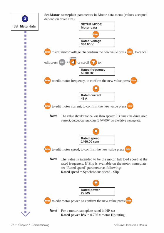
78 • Chapter 7 Commissioning ARTDriveL Instruction Manual
Set Motor nameplate parameters in Motor data menu (values accepteddepend on drive size):
⎡ ⎤SETUP MODEMotor data⎣ ⎦
⎡ ⎤Rated voltage380.00 V⎣ ⎦
to edit motor voltage. To confirm the new value press , to cancel
edit press + Escape
or scroll to:
⎡ ⎤Rated frequency50.00 Hz⎣ ⎦
to edit motor frequency, to confirm the new value press .
⎡ ⎤Rated current43 A⎣ ⎦
to edit motor current, to confirm the new value press .
NOTE! The value should not be less than approx 0.3 times the drive ratedcurrent, output current class 1 @400V on the drive nameplate.
⎡ ⎤Rated speed1460.00 rpm⎣ ⎦
to edit motor speed, to confirm the new value press .
NOTE! The value is intended to be the motor full load speed at therated frequency. If Slip is available on the motor nameplate,set “Rated speed” parameter as following:Rated speed = Synchronous speed - Slip
⎡ ⎤Rated power22 kW⎣ ⎦
to edit motor power, to confirm the new value press .
NOTE! For a motor nameplate rated in HP, setRated power kW = 0.736 x motor Hp rating.
3
Set Motor data

ARTDriveL Instruction Manual Chapter 7 Commissioning • 79
⎡ ⎤Cosfi0.85⎣ ⎦
to edit motor cos ϕ (power factor), to confirm the new value press .
NOTE! Leave default value for Cos ϕ if the data is not available fromthe nameplate.
⎡ ⎤Efficiency91.20 %⎣ ⎦
to edit motor efficiency, to confirm the new value press .
NOTE! Leave default value for efficiency if the data is not availablefrom the nameplate.
Press to exit from Motor data; for some seconds the drive will show:
⎡ ⎤BusyPlease wait ...⎣ ⎦
then⎡ ⎤SETUP MODE
Motor data⎣ ⎦
NOTE! If any changes have been made to Motor data menu parameters,with this operation internal drive values will be calculated andautotune results will be initialized.If the operation generates any error messages or alarm led comeson, please check consistency of motor parameters and try againor see specific directions in section 10, Troubleshooting.
Scroll to perform Autotune procedure; two options can be used forthis procedure: “Complete still” or “Complete rot”.
NOTE! When motor is coupled to gearbox and lift is installed, use“Complete still”(motor still).When motor is uncoupled or gearbox does not represent morethan 5% of load and lift car is not installed, use “Completerot”(motor in rotation).
WARNING ! Option “Complete still” may also cause limited shaftrotation.
4
Autotune

80 • Chapter 7 Commissioning ARTDriveL Instruction Manual
WARNING ! Option “Complete rot” causes motor shaft rotation close to ratedspeed. It is preferred one for the higher accuracy, but it requiresfree uncoupled rotation of the motor shaft.
⎡ ⎤SETUP MODEAutotune⎣ ⎦
Select the desired option (scroll or ):
⎡ ⎤Complete stillStart?⎣ ⎦
or⎡ ⎤Complete rot
Start?⎣ ⎦
As standard example with motor and machine installed on system, Completestill are used. Connect terminal 12 (Enable) to terminal 19 (+24VDC)through relays or local switch, switch on the output contactors and leavethe brake closed.
⎡ ⎤Complete stillStart?⎣ ⎦
⎡ ⎤Complete stillPress I Key⎣ ⎦
press to start
NOTE! Autotune can be aborted at any time by pressing .
The Autotune procedure will start; the drive will display:from
⎡ ⎤Complete still 10 %⎣ ⎦
to⎡ ⎤Complete still 1
100 %⎣ ⎦then
⎡ ⎤Complete still 20 %⎣ ⎦
to⎡ ⎤Complete still 2
100 %⎣ ⎦after

ARTDriveL Instruction Manual Chapter 7 Commissioning • 81
⎡ ⎤EndAutotune⎣ ⎦
blinking
Press 2 times to exit from the procedure:
⎡ ⎤SETUP MODEAutotune⎣ ⎦
Switch off the output contactors and disconnect terminal 12 (Enable).
NOTE! Autotune procedure can take up to different minutes to becompleted.
If the operation generates any error messages, for example when the driveis disabled during procedure execution:
⎡ ⎤Autotune err#1:Abort⎣ ⎦
and red LED alarm blinking
press to exit 2 times,
then try to repeat the autotune procedure. For more information abouterror messages and alarms, please refer to section 10, Troubleshooting.
Press to Exit from SETUP MODE menu.
Wait few seconds, message sequence will follow:⎡ ⎤Busy
Please wait ...⎣ ⎦then
⎡ ⎤RestartPlease wait ...⎣ ⎦
then⎡ ⎤R: S:
MONITOR⎣ ⎦then
⎡ ⎤Load setup?Yes->Ent No->Esc⎣ ⎦
Press to load Autotune data.
⎡ ⎤BusyPlease wait ...⎣ ⎦
then⎡ ⎤Load setup?
Yes->Ent No->Esc⎣ ⎦
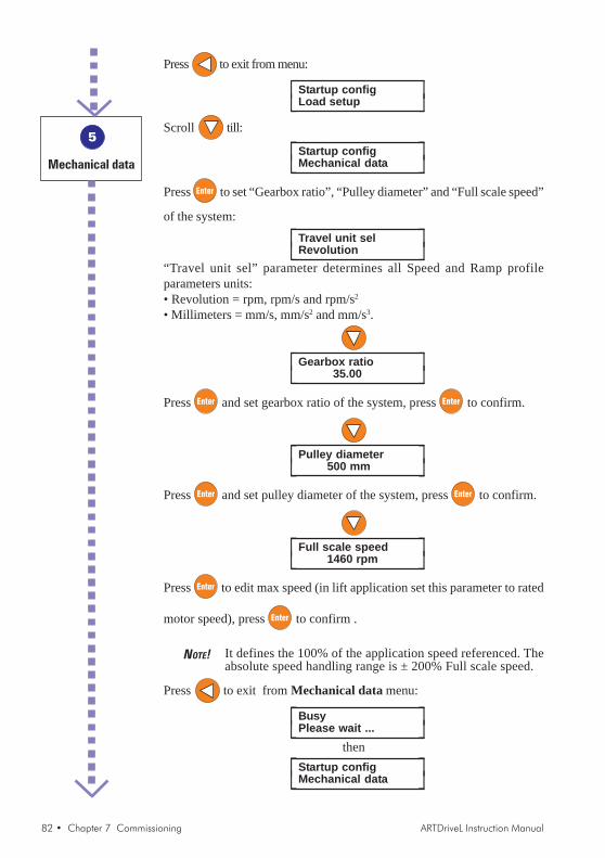
82 • Chapter 7 Commissioning ARTDriveL Instruction Manual
Press to exit from menu:
⎡ ⎤Startup configLoad setup⎣ ⎦
Scroll till:
⎡ ⎤Startup configMechanical data⎣ ⎦
Press to set “Gearbox ratio”, “Pulley diameter” and “Full scale speed”
of the system:
⎡ ⎤Travel unit selRevolution⎣ ⎦
“Travel unit sel” parameter determines all Speed and Ramp profileparameters units:• Revolution = rpm, rpm/s and rpm/s2
• Millimeters = mm/s, mm/s2 and mm/s3.
⎡ ⎤Gearbox ratio35.00⎣ ⎦
Press and set gearbox ratio of the system, press to confirm.
⎡ ⎤Pulley diameter500 mm⎣ ⎦
Press and set pulley diameter of the system, press to confirm.
⎡ ⎤Full scale speed1460 rpm⎣ ⎦
Press to edit max speed (in lift application set this parameter to rated
motor speed), press to confirm .
NOTE! It defines the 100% of the application speed referenced. Theabsolute speed handling range is ± 200% Full scale speed.
Press to exit from Mechanical data menu:
⎡ ⎤BusyPlease wait ...⎣ ⎦
then⎡ ⎤Startup config
Mechanical data⎣ ⎦
5
Mechanical data
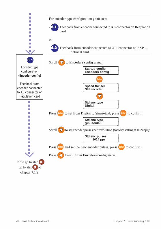
ARTDriveL Instruction Manual Chapter 7 Commissioning • 83
For encoder type configuration go to step:
- 6.16.16.16.16.1 Feedback from encoder connected to XE connector on Regulationcard
or
- 6.26.26.26.26.2 Feedback from encoder connected to XFI connector on EXP-...optional card
Scroll to Encoders config menu:
⎡ ⎤Startup configEncoders config⎣ ⎦
⎡ ⎤Speed fbk selStd encoder⎣ ⎦
⎡ ⎤Std enc typeDigital⎣ ⎦
Press to set from Digital to Sinusoidal, press to confirm:
⎡ ⎤Std enc typeSinusoidal⎣ ⎦
Scroll to set encoder pulses per revolution (factory setting = 1024ppr):
⎡ ⎤Std enc pulses1024 ppr⎣ ⎦
Press and set the new encoder pulses, press to confirm.
Press to exit from Encoders config menu.
6.1
Encoder typeconfiguration
(Encoder config)
Feedback fromencoder connectedto XE connector on
Regulation card
Now go to step 66666up to step 99999 ofchapter 7.1.3.
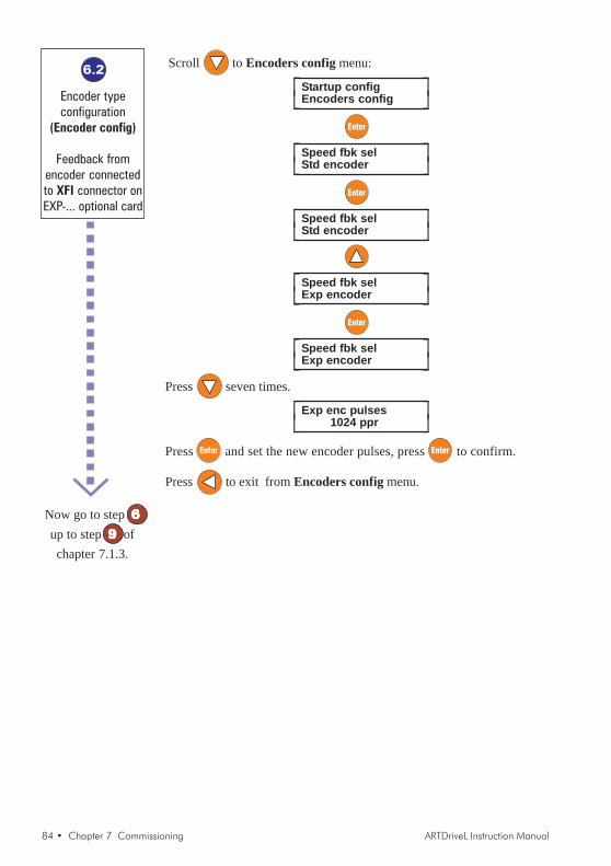
84 • Chapter 7 Commissioning ARTDriveL Instruction Manual
Scroll to Encoders config menu:
⎡ ⎤Startup configEncoders config⎣ ⎦
⎡ ⎤Speed fbk selStd encoder⎣ ⎦
⎡ ⎤Speed fbk selStd encoder⎣ ⎦
⎡ ⎤Speed fbk selExp encoder⎣ ⎦
⎡ ⎤Speed fbk selExp encoder⎣ ⎦
Press seven times.
⎡ ⎤Exp enc pulses1024 ppr⎣ ⎦
Press and set the new encoder pulses, press to confirm.
Press to exit from Encoders config menu.
6.2
Encoder typeconfiguration
(Encoder config)
Feedback fromencoder connectedto XFI connector onEXP-... optional card
Now go to step 66666up to step 99999 ofchapter 7.1.3.
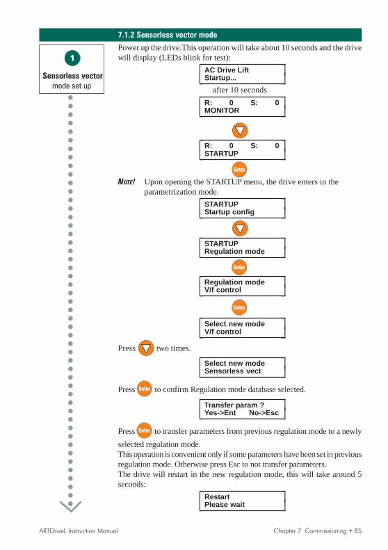
ARTDriveL Instruction Manual Chapter 7 Commissioning • 85
7.1.2 Sensorless vector mode
Power up the drive.This operation will take about 10 seconds and the drivewill display (LEDs blink for test):
⎡ ⎤AC Drive LiftStartup...⎣ ⎦
after 10 seconds⎡ ⎤R: 0 S: 0
MONITOR⎣ ⎦
⎡ ⎤R: 0 S: 0STARTUP⎣ ⎦
NOTE! Upon opening the STARTUP menu, the drive enters in theparametrization mode.
⎡ ⎤STARTUPStartup config⎣ ⎦
⎡ ⎤STARTUPRegulation mode⎣ ⎦
⎡ ⎤Regulation modeV/f control⎣ ⎦
⎡ ⎤Select new modeV/f control⎣ ⎦
Press two times.
⎡ ⎤Select new modeSensorless vect⎣ ⎦
Press to confirm Regulation mode database selected.
⎡ ⎤Transfer param ?Yes->Ent No->Esc⎣ ⎦
Press to transfer parameters from previous regulation mode to a newlyselected regulation mode.This operation is convenient only if some parameters have been set in previousregulation mode. Otherwise press Esc to not transfer parameters.The drive will restart in the new regulation mode, this will take around 5seconds:
⎡ ⎤RestartPlease wait⎣ ⎦
1
Sensorless vectormode set up

86 • Chapter 7 Commissioning ARTDriveL Instruction Manual
then⎡ ⎤STARTUP
Regulation mode⎣ ⎦
Press to exit from STARTUP menu.
7.1.3 V/f Control mode
Power up the drive.This operation will take about 10 seconds and the drivewill display (LEDs blink for test):
⎡ ⎤AC Drive LiftStartup...⎣ ⎦
after 10 seconds⎡ ⎤R: 0 S: 0
MONITOR⎣ ⎦
⎡ ⎤R: 0 S: 0STARTUP⎣ ⎦
NOTE! Upon opening the STARTUP menu, the drive enters in theparametrization mode.
⎡ ⎤STARTUPStartup config⎣ ⎦
⎡ ⎤STARTUP CONFIGEnter setup mode⎣ ⎦
, wait few seconds:
⎡ ⎤SETUP MODEDrive data⎣ ⎦
⎡ ⎤Mains voltage400 V⎣ ⎦
Press or to select AC input voltage from the following list:
460 - 440 - 415 - 400 - 380 - 230V, press to confirm.If necessary, it is also possible to change : Ambient temperature andSwitching frequency.
1
V/f Controlswitch-on
2
V/f Controlmode set up
Now go to step 22222up to step 99999 ofchapter 7.1.3.

ARTDriveL Instruction Manual Chapter 7 Commissioning • 87
⎡ ⎤Ambient temp40° C⎣ ⎦
⎡ ⎤Switching freq8 Khz⎣ ⎦
Press , the drive will show:
⎡ ⎤BusyPlease wait ...⎣ ⎦
then⎡ ⎤SETUP MODE
Drive data⎣ ⎦
Set Motor nameplate parameters in Motor data menu (values accepteddepend on drive size):
⎡ ⎤SETUP MODEMotor data⎣ ⎦
⎡ ⎤Rated voltage380.00 V⎣ ⎦
to edit motor voltage. To confirm the new value press , to cancel
edit press + Escape
or scroll to:
⎡ ⎤Rated frequency50.00 Hz⎣ ⎦
to edit motor frequency, to confirm the new value press
⎡ ⎤Rated current43 A⎣ ⎦
to edit motor current, to confirm the new value press .
NOTE! The value should not be less than approx 0.3 times the drive ratedcurrent, output current class 1 @400V on the drive nameplate.
⎡ ⎤Rated speed1460.00 rpm⎣ ⎦
3
Set Motor data
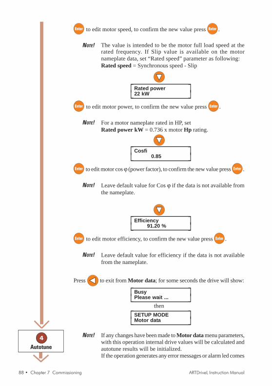
88 • Chapter 7 Commissioning ARTDriveL Instruction Manual
to edit motor speed, to confirm the new value press .
NOTE! The value is intended to be the motor full load speed at therated frequency. If Slip value is available on the motornameplate data, set “Rated speed” parameter as following:Rated speed = Synchronous speed - Slip
⎡ ⎤Rated power22 kW⎣ ⎦
to edit motor power, to confirm the new value press .
NOTE! For a motor nameplate rated in HP, setRated power kW = 0.736 x motor Hp rating.
⎡ ⎤Cosfi0.85⎣ ⎦
to edit motor cos ϕ (power factor), to confirm the new value press .
NOTE! Leave default value for Cos ϕ if the data is not available fromthe nameplate.
⎡ ⎤Efficiency91.20 %⎣ ⎦
to edit motor efficiency, to confirm the new value press .
NOTE! Leave default value for efficiency if the data is not availablefrom the nameplate.
Press to exit from Motor data; for some seconds the drive will show:
⎡ ⎤BusyPlease wait ...⎣ ⎦
then⎡ ⎤SETUP MODE
Motor data⎣ ⎦
NOTE! If any changes have been made to Motor data menu parameters,with this operation internal drive values will be calculated andautotune results will be initialized.If the operation generates any error messages or alarm led comes
4
Autotune

ARTDriveL Instruction Manual Chapter 7 Commissioning • 89
on, please check consistency of motor parameters and try againor refer to section 10, Troubleshooting.
Scroll to perform Autotune procedure; two options can be used forthis procedure: “Complete still” or “Complete rot”.
NOTE! When motor is coupled to gearbox and lift is installed, use“Complete still”(motor still).When motor is uncoupled or gearbox does not represent morethan 5% of load and lift car is not installed, use “Completerot”(motor on rotation).
WARNING ! Option “Complete still” may also cause limited shaftrotation.
WARNING ! Option “Complete rot” causes motor shaft rotation close to ratedspeed. It is preferred one for the higher accuracy, but it requiresfree uncoupled rotation of the motor shaft.
⎡ ⎤SETUP MODEAutotune⎣ ⎦
Select the desired option (scroll or ):
⎡ ⎤Complete stillStart?⎣ ⎦
or⎡ ⎤Complete rot
Start?⎣ ⎦
As standard example with motor and machine installed on system, Completestill are used. Connect terminal 12 (Enable) to terminal 19 (+24VDC)through relays or local switch, switch on the output contactors and leavethe brake closed.
⎡ ⎤Complete stillStart?⎣ ⎦
⎡ ⎤Complete stillPress I Key⎣ ⎦
press to start
NOTE! Autotune can be aborted at any time by pressing .

90 • Chapter 7 Commissioning ARTDriveL Instruction Manual
The Autotune procedure will start through which the drive will display:from
⎡ ⎤Complete still 10 %⎣ ⎦
to⎡ ⎤Complete still 1
100 %⎣ ⎦then
⎡ ⎤Complete still 20 %⎣ ⎦
to⎡ ⎤Complete still 2
100 %⎣ ⎦after
⎡ ⎤EndAutotune⎣ ⎦
blinking
Press 2 times to exit from the procedure:
⎡ ⎤SETUP MODEAutotune⎣ ⎦
Switch off the output contactors and disconnect terminal 12 (Enable).
NOTE! Autotune procedure can take up to different minutes to becompleted.
If the operation generates any error messages, for example when the driveis disabled during procedure execution:
⎡ ⎤Autotune err#1:Abort⎣ ⎦
and red LED alarm blinking
press to exit 2 times,
then try to repeat the autotune procedure. For more information abouterror messages and alarms, please refer to section 10, Troubleshooting.
Press to Exit from SETUP MODE menu.
Wait few seconds, message sequence will follow:⎡ ⎤Busy
Please wait ...⎣ ⎦then
⎡ ⎤RestartPlease wait ...⎣ ⎦
then
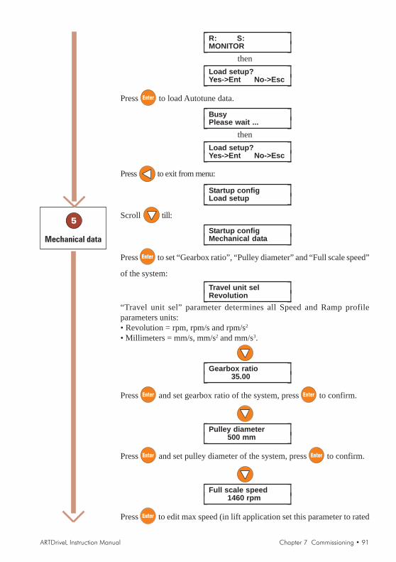
ARTDriveL Instruction Manual Chapter 7 Commissioning • 91
⎡ ⎤R: S:MONITOR⎣ ⎦
then⎡ ⎤Load setup?
Yes->Ent No->Esc⎣ ⎦
Press to load Autotune data.
⎡ ⎤BusyPlease wait ...⎣ ⎦
then⎡ ⎤Load setup?
Yes->Ent No->Esc⎣ ⎦
Press to exit from menu:
⎡ ⎤Startup configLoad setup⎣ ⎦
Scroll till:
⎡ ⎤Startup configMechanical data⎣ ⎦
Press to set “Gearbox ratio”, “Pulley diameter” and “Full scale speed”
of the system:
⎡ ⎤Travel unit selRevolution⎣ ⎦
“Travel unit sel” parameter determines all Speed and Ramp profileparameters units:• Revolution = rpm, rpm/s and rpm/s2
• Millimeters = mm/s, mm/s2 and mm/s3.
⎡ ⎤Gearbox ratio35.00⎣ ⎦
Press and set gearbox ratio of the system, press to confirm.
⎡ ⎤Pulley diameter500 mm⎣ ⎦
Press and set pulley diameter of the system, press to confirm.
⎡ ⎤Full scale speed1460 rpm⎣ ⎦
Press to edit max speed (in lift application set this parameter to rated
5
Mechanical data
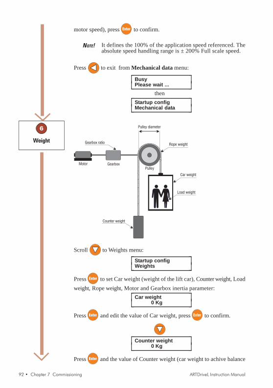
92 • Chapter 7 Commissioning ARTDriveL Instruction Manual
motor speed), press to confirm.
NOTE! It defines the 100% of the application speed referenced. Theabsolute speed handling range is ± 200% Full scale speed.
Press to exit from Mechanical data menu:
⎡ ⎤BusyPlease wait ...⎣ ⎦
then⎡ ⎤Startup config
Mechanical data⎣ ⎦
PulleyMotor Gearbox
Pulley diameter
Rope weight
Car weight
Load weight
Counter weight
Gearbox ratio
Scroll to Weights menu:
⎡ ⎤Startup configWeights⎣ ⎦
Press to set Car weight (weight of the lift car), Counter weight, Loadweight, Rope weight, Motor and Gearbox inertia parameter:
⎡ ⎤Car weight0 Kg⎣ ⎦
Press and edit the value of Car weight, press to confirm.
⎡ ⎤Counter weight0 Kg⎣ ⎦
Press and the value of Counter weight (car weight to achive balance
6
Weight

ARTDriveL Instruction Manual Chapter 7 Commissioning • 93
system) parameter, press to confirm.
⎡ ⎤Load weight0 Kg⎣ ⎦
Press and edit the value of Load weight (maximum lift load weight)
parameter, press to confirm.
⎡ ⎤Rope weight0 Kg⎣ ⎦
Press and edit the value of Rope weight (total inertia of cabin rope)
parameter, press to confirm.
⎡ ⎤Motor inertia0.00 Kg*m2⎣ ⎦
Press and edit the value of Motor inertia (if not available, leave to
default), press to confirm.
⎡ ⎤Gearbox inertia0.00 Kg*m2⎣ ⎦
Press and edit the value of Gearbox inertia (if not available, leave to
default), press to confirm.
NOTE! “Gearbox inertia” is intended as inertia of all rotating masseson slow side of gearbox, ex. pulley inertia, etc...
Press to exit from Weight menu.
Press 2 times.Follow the points below to set the BU resistance parameters:
⎡ ⎤Startup configBU protection⎣ ⎦
7
Braking unit setting[BU protection]

94 • Chapter 7 Commissioning ARTDriveL Instruction Manual
⎡ ⎤BU controlInternal⎣ ⎦
⎡ ⎤BU resistance15.40 ohm⎣ ⎦
Press and edit the resistance value, press to confirm.
NOTE! See section 4.9.2 for the minimum permissible value of the resistor.
For the thermal protection of the braking resistence, a time reversecharacteristic is defined. This requires definition of resistor power incontinous service, BU res cont pwr.
NOTE! Refer to chapter 9.2 for details on BU protection
⎡ ⎤BU res cont pwr4.00 kW⎣ ⎦
Press to edit the power value, press to confirm.
Press to exit from Encoder Config menu.
⎡ ⎤Startup configBU protection⎣ ⎦
⎡ ⎤BusyPlease wait ...⎣ ⎦
to⎡ ⎤STARTUP
Save config?⎣ ⎦
The prompt displays “Save config ?” (Recommended).For this operation the drive will take around 5 seconds.
Press to execute the procedure:
⎡ ⎤STARTUPSave config?⎣ ⎦
⎡ ⎤R: S:STARTUP⎣ ⎦
NOTE! Upon closing the STARTUP menu, the drive exits fromparametrization mode and becomes operational.

ARTDriveL Instruction Manual Chapter 7 Commissioning • 95
NOTE! The drive cannot be enabled when STARTUP menu is open.
AVyL drive allows to set a Speed profile trough 8 different speed point:“Multi speed 0” ... “Multi speed 7”
⎡ ⎤R: S:STARTUP⎣ ⎦
⎡ ⎤R: S:TRAVEL⎣ ⎦
⎡ ⎤TRAVELSpeed profile⎣ ⎦
⎡ ⎤Smooth start spd0 rpm⎣ ⎦
⎡ ⎤Multi speed 00 rpm⎣ ⎦
Press to set “Multi speed 0” set point:
⎡ ⎤Multi speed 0+00000000 rpm⎣ ⎦
Edit the value requested by the system and press to confirm.
Scroll to set “Multi speed 1” set point:
⎡ ⎤Multi speed 10 rpm⎣ ⎦
Press and repeat the procedure as for “Multi speed 0”. Scroll to
set all the others Multi speed required by the system.
ATTENTION ! Through the combination of “Mlt spd s0 src” (equal Digitalinput 4), “Mlt spd s1 src” (equal Digital input 5) and “Mltspd s2 src” (equal Digital input 6), is possible to selectMulti speed desired, according to next table:
8
Speed setting[Speed profile]

96 • Chapter 7 Commissioning ARTDriveL Instruction Manual
Mtl spd sel
2 src
Mtl spd sel
1 src
Mtl spd sel
0 srcACTIVE SPEED
0 0 0 Multi speed 0
0 0 1 Multi speed 1
0 1 0 Multi speed 2
0 1 1 Multi speed 3
1 0 0 Multi speed 4
1 0 1 Multi speed 5
1 1 0 Multi speed 6
1 1 1 Multi speed 7TAV3i011
Press to exit from Speed profile menu.
AVyL drive allows to set a Ramp profile as the picture shows below:
Speed ref
Multispeed
MR0 acc ini jerk
MR0 acceleration
MR0 acc end jerk
Speed refMultispeed
Multispeed
MR0 dec ini jerk MR0 deceleration
MR0 dec end jerkAcceleration
MR0 end decel
Acceleration
⎡ ⎤TRAVELSpeed profile⎣ ⎦
⎡ ⎤TRAVELRamp profile⎣ ⎦
9
Ramp setting[Ramp profile]

ARTDriveL Instruction Manual Chapter 7 Commissioning • 97
⎡ ⎤MR0 acc ini jerk1000 rpm/s2⎣ ⎦
Press to set “MR0 acc ini jerk” parameter, press to confirm:
⎡ ⎤MR0 acceleration500 rpm/s⎣ ⎦
Press to set “MR0 acceleration” parameter, press to confirm:
⎡ ⎤MR0 acc end jerk1000 rpm/s2⎣ ⎦
Press to set “MR0 acc end jerk” parameter, press to confirm:
⎡ ⎤MR0 dec ini jerk1000 rpm/s2⎣ ⎦
Press to set “MR0 dec ini jerk” parameter, press to confirm.
⎡ ⎤MR0 deceleration500 rpm/s⎣ ⎦
Press to set “MR0 deceleration” parameter, press to confirm.
⎡ ⎤MR0 dec end jerk1000 rpm/s2⎣ ⎦
Press to set “MR0 dec end jerk” parameter, press to confirm.
⎡ ⎤MR0 end decel1000 rpm/s⎣ ⎦
Press to set “MR0 end decel” parameter, press to confirm.
⎡ ⎤TRAVELRamp profile⎣ ⎦
Press 9 times to open the saving procedure
⎡ ⎤TRAVELSAVE PARAMETERS⎣ ⎦

98 • Chapter 7 Commissioning ARTDriveL Instruction Manual
Press to execute the procedure:
⎡ ⎤BusyPlease wait ...⎣ ⎦
to⎡ ⎤TRAVEL
SAVE PARAMETERS⎣ ⎦
Press + .
⎡ ⎤R: 0 S: 0MONITOR⎣ ⎦
Now the drive isset with
commands forstandardsequence.

ARTDriveL Instruction Manual Chapter 7 Commissioning • 99
7.2 Commissioning for AVy...BR / BR4 (Brushless Motors)
Commissioning Set-up Procedure
Function
Set Drive data
Set Motor data
Run current RegulatorAutotune
Escape setup mode
Set all systemmechanical data
Set all systemweight data
Encoder configuration
Set braking unitparameters
Save configurationmade in startup menu
Set speed profile
Set ramp profile
Encoder phasing
Save all the parameters
Description
Drive Data parameters: Mains voltage, Ambient temp,Switching freq, Speed reference resolution
Motor Data parameters: Rated voltage, Rated current,Rated speed, Pole pairs, Torque constant, EMF constant,Stator resistance and LsS inductance.
Autotune procedure measures a real motor parameters:- “Curr Reg autotune” can be used when motor is coupledto gearbox and lift car is installed. It could cause limitedshaft rotation.
During this operation a “Load setup” is required to loadall datas changes into SETUP MODE.
System mechanical data:Gearbox ratio, Pulley diameter, Full scale speed.
System weights data:Cabin weight, Counter weight, Load weight, Ropeweight, Motor inertia, Gearbox inertia
Feedback source type selection: Sinusoidal Hall,Sinusoidal SinCos, Sinusoidal Extern, Digital Hall,DigitalExtern, SinCos, Resolver and Hyperface.
Braking Unit parameters: Braking unit type (internal /external), Braking unit resistance, Braking unit power
Use “Save Config ?” to save all the changes made in theStartup menu.
A binary combination of three digital input allows toselect up to 8 different speed setpoints
Accelerations jerk and decelerations jerk can be set inthe ramp profile
Two options are available:- motor rotating or still.
Step
1
2
3
4
5
6
7
9
10
11
12
13
8
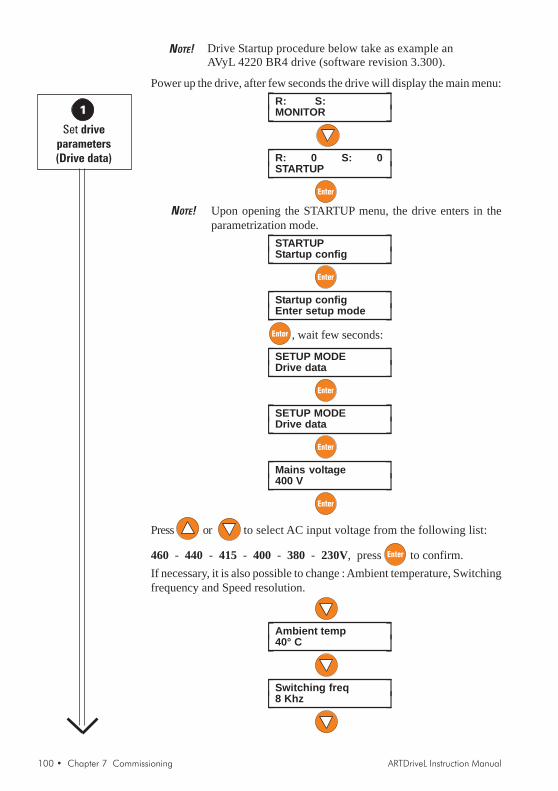
100 • Chapter 7 Commissioning ARTDriveL Instruction Manual
NOTE! Drive Startup procedure below take as example anAVyL 4220 BR4 drive (software revision 3.300).
Power up the drive, after few seconds the drive will display the main menu:⎡ ⎤R: S:
MONITOR⎣ ⎦
⎡ ⎤R: 0 S: 0STARTUP⎣ ⎦
NOTE! Upon opening the STARTUP menu, the drive enters in theparametrization mode.
⎡ ⎤STARTUPStartup config⎣ ⎦
⎡ ⎤Startup configEnter setup mode⎣ ⎦
, wait few seconds:
⎡ ⎤SETUP MODEDrive data⎣ ⎦
⎡ ⎤SETUP MODEDrive data⎣ ⎦
⎡ ⎤Mains voltage400 V⎣ ⎦
Press or to select AC input voltage from the following list:
460 - 440 - 415 - 400 - 380 - 230V, press to confirm.If necessary, it is also possible to change : Ambient temperature, Switchingfrequency and Speed resolution.
⎡ ⎤Ambient temp40° C⎣ ⎦
⎡ ⎤Switching freq8 Khz⎣ ⎦
1
Set driveparameters(Drive data)

ARTDriveL Instruction Manual Chapter 7 Commissioning • 101
⎡ ⎤Spd ref/fbk res0.250 rpm⎣ ⎦
Press or to select a speed resolution value based on max motorspeed.
E.g.: if rated speed is 144 rpm, set 0.03125 rpm (see table)
Speed resolution Max speed value(Spd ref/fbk res) 0.125 rpm 2048 rpm 0.25 rpm 4096 rpm 0.5 rpm 8192 rpm 1 rpm 16384rpm 0.03125 rpm 512 rpm
⎡ ⎤Spd ref/fbk res0.03125 rpm⎣ ⎦
Press to confirm the selection.
Press , the drive will show:
⎡ ⎤BusyPlease wait ...⎣ ⎦
then⎡ ⎤SETUP MODE
Drive data⎣ ⎦
Set Motor nameplate parameters in Motor data menu (values accepteddepend on drive size):
⎡ ⎤Rated voltage330.00 V⎣ ⎦
Press to edit rated motor voltage.
Press again to confirm the new value.
⎡ ⎤Rated current35 A⎣ ⎦
Press to edit rated motor current. Press again to confirm.
2
Set motorparameters
(Motor data)

102 • Chapter 7 Commissioning ARTDriveL Instruction Manual
⎡ ⎤Rated speed2000.00 rpm⎣ ⎦
Press to edit rated synchronous motor speed. Press again toconfirm the value.
⎡ ⎤Pole pairs4⎣ ⎦
Press to edit motor pole pairs. Press again to confirm the value.
⎡ ⎤Torque Constant2.480 Nm/A⎣ ⎦
Press to edit motor torque value. Press again to confirm the value.
NOTE! If Torque Constant is not available, it should be calculated withthe following:
K =T1
Pn
2 S
60n
In
Where:P = Rated power [W]
I = Rated current [A]
S = Rated speed [rpm]
n
n
n
K =T1
Tn
In
Where:T = Rated torque [Nm]
I = Rated current [A]n
n
⎡ ⎤EMF constant1.430 V*s⎣ ⎦
Press to edit motor back EMF constant from motor type plate (*).
Press to confirm.
⎡ ⎤Stator resist0.135 ohm⎣ ⎦
Press to edit motor stator resistance value (*). Press to confirm.
⎡ ⎤LsS inductance0.00237 H⎣ ⎦
Press to edit motor stator value (*). Press to confirm.
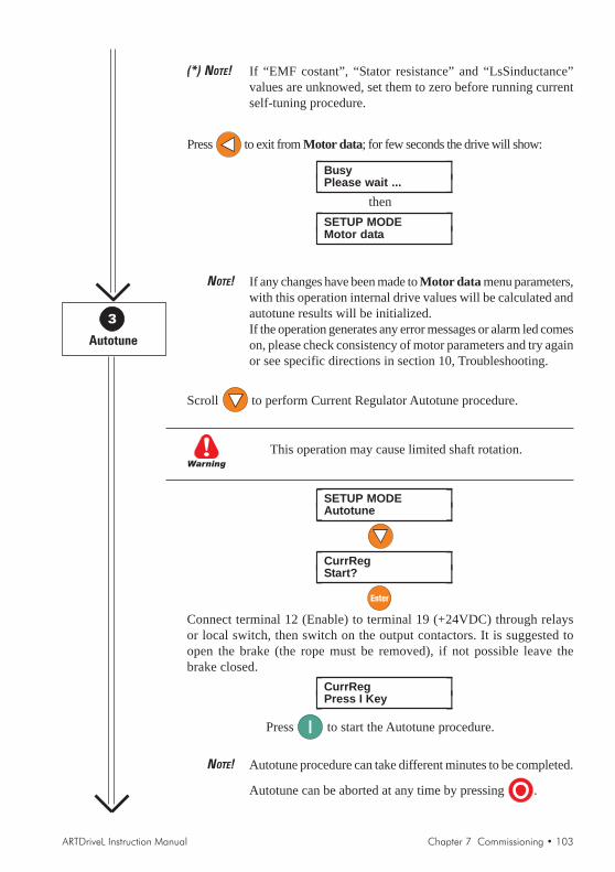
ARTDriveL Instruction Manual Chapter 7 Commissioning • 103
(*) NOTE! If “EMF costant”, “Stator resistance” and “LsSinductance”values are unknowed, set them to zero before running currentself-tuning procedure.
Press to exit from Motor data; for few seconds the drive will show:
⎡ ⎤BusyPlease wait ...⎣ ⎦
then⎡ ⎤SETUP MODE
Motor data⎣ ⎦
NOTE! If any changes have been made to Motor data menu parameters,with this operation internal drive values will be calculated andautotune results will be initialized.If the operation generates any error messages or alarm led comeson, please check consistency of motor parameters and try againor see specific directions in section 10, Troubleshooting.
Scroll to perform Current Regulator Autotune procedure.
Warning
This operation may cause limited shaft rotation.
⎡ ⎤SETUP MODEAutotune⎣ ⎦
⎡ ⎤CurrRegStart?⎣ ⎦
Connect terminal 12 (Enable) to terminal 19 (+24VDC) through relaysor local switch, then switch on the output contactors. It is suggested toopen the brake (the rope must be removed), if not possible leave thebrake closed.
⎡ ⎤CurrRegPress I Key⎣ ⎦
Press to start the Autotune procedure.
NOTE! Autotune procedure can take different minutes to be completed.
Autotune can be aborted at any time by pressing .
3
Autotune

104 • Chapter 7 Commissioning ARTDriveL Instruction Manual
The drive will display from:⎡ ⎤CurrReg
0 %⎣ ⎦to
⎡ ⎤CurrReg100 %⎣ ⎦
after⎡ ⎤End
Autotune⎣ ⎦blinking to show the end of procedure.
Press 2 times to exit from the procedure:
⎡ ⎤SETUP MODEAutotune⎣ ⎦
Switch off the output contactors and disconnect terminal 12 (Enable).
Press and wait few seconds
⎡ ⎤Load setup?Yes->Ent No->Esc⎣ ⎦
⎡ ⎤BusyPlease wait ...⎣ ⎦
then⎡ ⎤Load setup?
Yes->Ent No->Esc⎣ ⎦
Press to exit from menu:
⎡ ⎤Startup configLoad setup⎣ ⎦
Scroll till:
⎡ ⎤Startup configMechanical data⎣ ⎦
Press to set “Gearbox ratio”, “Pulley diameter” and “Full scale speed”
of the system:
⎡ ⎤Travel unit selRevolution⎣ ⎦
“Travel unit sel” parameter determines all Speed and Ramp profileparameters units:• Revolution = rpm, rpm/s and rpm/s2
• Millimeters = mm/s, mm/s2 and mm/s3.
5
Mechanical data
4
Load setup

ARTDriveL Instruction Manual Chapter 7 Commissioning • 105
Press and or to select the units, press to confirm.
⎡ ⎤Gearbox ratio35.00⎣ ⎦
Press to set gearbox ratio of the system, press to confirm.
⎡ ⎤Pulley diameter500 mm⎣ ⎦
Press and edit the pulley diameter of the system, press toconfirm.
⎡ ⎤Pulley diameter+0000500 mm⎣ ⎦
to Full scale speed parameter
⎡ ⎤Full scale speed2000 rpm⎣ ⎦
Press and edit the value of max speed (in lift application set this
parameter to rated motor speed), press to confirm. Press toexit from Mechanical data menu.
Scroll to Weights menu:
⎡ ⎤Startup configWeights⎣ ⎦
PulleyMotor Gearbox
Pulley diameter
Rope weight
Car weight
Load weight
Counter weight
Gearbox ratio
Press to set Car weight (weight of the lift car), Counter weight, Loadweight, Rope weight, Motor and Gearbox inertia parameter:
6
Weights
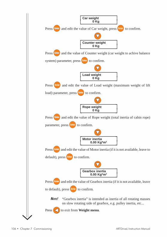
106 • Chapter 7 Commissioning ARTDriveL Instruction Manual
⎡ ⎤Car weight0 Kg⎣ ⎦
Press and edit the value of Car weight, press to confirm.
⎡ ⎤Counter weight0 Kg⎣ ⎦
Press and the value of Counter weight (car weight to achive balance
system) parameter, press to confirm.
⎡ ⎤Load weight0 Kg⎣ ⎦
Press and edit the value of Load weight (maximum weight of lift
load) parameter, press to confirm.
⎡ ⎤Rope weight0 Kg⎣ ⎦
Press and edit the value of Rope weight (total inertia of cabin rope)
parameter, press to confirm.
⎡ ⎤Motor inertia0.00 Kg*m2⎣ ⎦
Press and edit the value of Motor inertia (if it is not available, leave to
default), press to confirm.
⎡ ⎤Gearbox inertia0.00 Kg*m2⎣ ⎦
Press and edit the value of Gearbox inertia (if it is not available, leave
to default), press to confirm.
NOTE! “Gearbox inertia” is intended as inertia of all rotating masseson slow rotating side of gearbox, e.g. pulley inertia, etc...
Press to exit from Weight menu.

ARTDriveL Instruction Manual Chapter 7 Commissioning • 107
Press 2 times.
⎡ ⎤Startup configEncoders config⎣ ⎦
⎡ ⎤Speed fbk selStd encoder⎣ ⎦
⎡ ⎤Std enc typeSinusoidal Hall⎣ ⎦
Press to select the parameter (see following list) according to the
encoder type, press to confirm.
Parameter Description
SinusoidalHall is a sinusoidal incremental encoder with A+/A-,B+/B-,C+/C-traces and three digital “Hall sensor” absolute positiontraces for initial synchronization (XE connector)
SinusoidalSinCos is a sinusoidal incremental encoderwith A+/A-,B+/B-,C+/C- traces and two analog Sin Cos absolute positiontraces for initial synchronization (XE connector).
SinusoidalExtern is a sinusoidal incremental encoder with A+/A-,B+/B-traces and absolute position information through SSI serialinterface for initial synchronization (XE connector,requires APC100y card).
DigitalHall is a digital incremental encoder with A+/A-,B+/B-,C+/C- traces and three digital “Hall sensor” absolute positiontraces for initial synchronization (XE connector).
DigitalExtern is a digital incremental encoder with A+/A-,B+/B- tracesand absolute position information through SSI serialinterface for initial synchronization (XE connector,requires APC100y card).
SinCos is a sinusoidal absolute encoder with SinCos traces.Resolver is resolver feedback, using option cards: EXP-RES, refer
its manual for details (XFR connector on EXP-REScard).
SinusoidalHiperface Absolute encoder with Hiperface protocol (XEconnector).
Sinusoidal Intern sinusoidal incremental encoder with A+/A-,B+/B-,C+/C- traces, absolute position traces are not necessarybecause phasing is performed automatically at every start.
Digital Intern digital incremental encoder with A+/A-,B+/B-,C+/C-traces, absolute position traces are not necessary becausephasing is performed automatically at every start.
7
Encoder typeconfiguration
(Encoder config)

108 • Chapter 7 Commissioning ARTDriveL Instruction Manual
CAUTION! For each encoder feedback, set the correct jumpersconfiguration on the regulation card RV33.
⎡ ⎤Std enc typeSinusoidalSinCos⎣ ⎦
⎡ ⎤Std enc pulses1024 ppr⎣ ⎦
Press to edit the number according to encoder data, press toconfirm.
NOTE! It is possible to use only encoder having pulses per revolutionequal to a multiple of 2.Example: 512 ppr, 1024 ppr, 2048 ppr, etc.
Press to exit from Encoder Config menu.
Press 2 times.
Follow the points below to set the BU resistance parameters:⎡ ⎤Startup config
BU protection⎣ ⎦
⎡ ⎤BU controlInternal⎣ ⎦
⎡ ⎤BU resistance15.40 ohm⎣ ⎦
Press and edit the resistance value, press to confirm.
NOTE! See section 4.9.2 for the minimum permissible value of the resistor.
For the thermal protection of the braking resistence, a time reversecharacteristic is defined. This requires definition of resistor power incontinous service, BU res cont pwr.
NOTE! Refer to chapter 9.2 for details on BU protection
⎡ ⎤BU res cont pwr4.00 kW⎣ ⎦
Press to edit the power value, press to confirm.
8
Braking unit setting[BU protection]
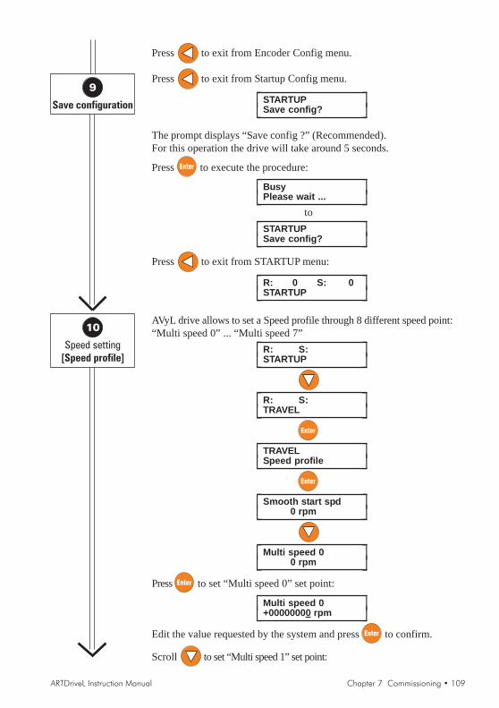
ARTDriveL Instruction Manual Chapter 7 Commissioning • 109
Press to exit from Encoder Config menu.
Press to exit from Startup Config menu.
⎡ ⎤STARTUPSave config?⎣ ⎦
The prompt displays “Save config ?” (Recommended).For this operation the drive will take around 5 seconds.
Press to execute the procedure:
⎡ ⎤BusyPlease wait ...⎣ ⎦
to⎡ ⎤STARTUP
Save config?⎣ ⎦
Press to exit from STARTUP menu:
⎡ ⎤R: 0 S: 0STARTUP⎣ ⎦
AVyL drive allows to set a Speed profile through 8 different speed point:“Multi speed 0” ... “Multi speed 7”
⎡ ⎤R: S:STARTUP⎣ ⎦
⎡ ⎤R: S:TRAVEL⎣ ⎦
⎡ ⎤TRAVELSpeed profile⎣ ⎦
⎡ ⎤Smooth start spd0 rpm⎣ ⎦
⎡ ⎤Multi speed 00 rpm⎣ ⎦
Press to set “Multi speed 0” set point:
⎡ ⎤Multi speed 0+00000000 rpm⎣ ⎦
Edit the value requested by the system and press to confirm.
Scroll to set “Multi speed 1” set point:
9
Save configuration
10
Speed setting[Speed profile]
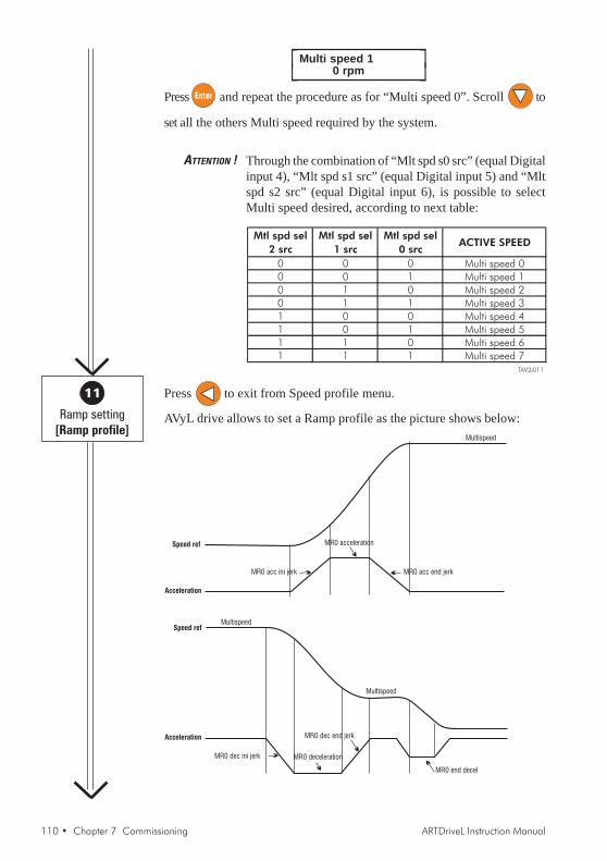
110 • Chapter 7 Commissioning ARTDriveL Instruction Manual
⎡ ⎤Multi speed 10 rpm⎣ ⎦
Press and repeat the procedure as for “Multi speed 0”. Scroll to
set all the others Multi speed required by the system.
ATTENTION ! Through the combination of “Mlt spd s0 src” (equal Digitalinput 4), “Mlt spd s1 src” (equal Digital input 5) and “Mltspd s2 src” (equal Digital input 6), is possible to selectMulti speed desired, according to next table:
Mtl spd sel
2 src
Mtl spd sel
1 src
Mtl spd sel
0 srcACTIVE SPEED
0 0 0 Multi speed 0
0 0 1 Multi speed 1
0 1 0 Multi speed 2
0 1 1 Multi speed 3
1 0 0 Multi speed 4
1 0 1 Multi speed 5
1 1 0 Multi speed 6
1 1 1 Multi speed 7TAV3i011
Press to exit from Speed profile menu.
AVyL drive allows to set a Ramp profile as the picture shows below:
Speed ref
Multispeed
MR0 acc ini jerk
MR0 acceleration
MR0 acc end jerk
Speed refMultispeed
Multispeed
MR0 dec ini jerk MR0 deceleration
MR0 dec end jerkAcceleration
MR0 end decel
Acceleration
11
Ramp setting[Ramp profile]

ARTDriveL Instruction Manual Chapter 7 Commissioning • 111
⎡ ⎤TRAVELSpeed profile⎣ ⎦
⎡ ⎤TRAVELRamp profile⎣ ⎦
⎡ ⎤MR0 acc ini jerk1000 rpm/s2⎣ ⎦
Press to set “MR0 acc ini jerk” parameter, press to confirm:
⎡ ⎤MR0 acceleration500 rpm/s⎣ ⎦
Press to set “MR0 acceleration” parameter, press to confirm:
⎡ ⎤MR0 acc end jerk1000 rpm/s2⎣ ⎦
Press to set “MR0 acc end jerk” parameter, press to confirm:
⎡ ⎤MR0 dec ini jerk1000 rpm/s2⎣ ⎦
Press to set “MR0 dec ini jerk” parameter, press to confirm.
⎡ ⎤MR0 deceleration500 rpm/s⎣ ⎦
Press to set “MR0 deceleration” parameter, press to confirm.
⎡ ⎤MR0 dec end jerk1000 rpm/s2⎣ ⎦
Press to set “MR0 dec end jerk” parameter, press to confirm.
⎡ ⎤MR0 end decel1000 rpm/s⎣ ⎦
Press to set “MR0 end decel” parameter, press to confirm.
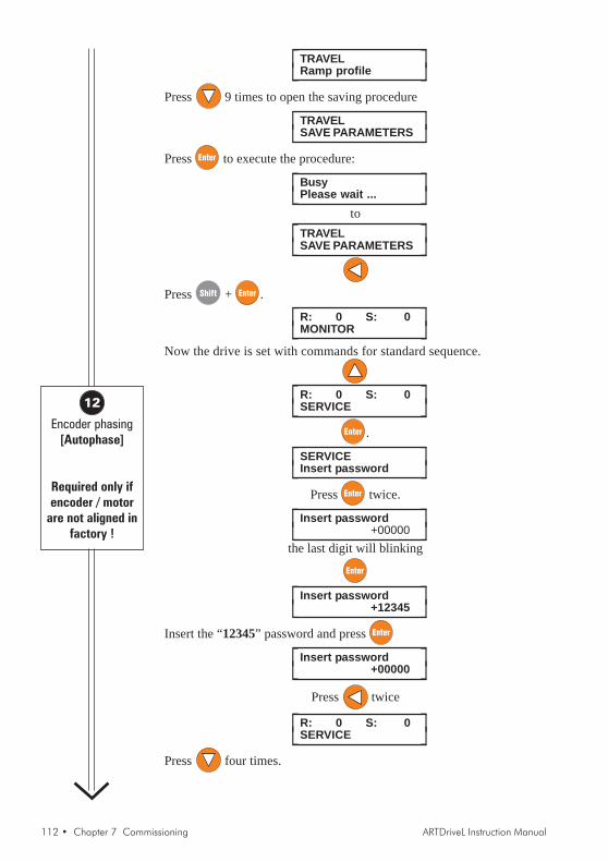
112 • Chapter 7 Commissioning ARTDriveL Instruction Manual
⎡ ⎤TRAVELRamp profile⎣ ⎦
Press 9 times to open the saving procedure
⎡ ⎤TRAVELSAVE PARAMETERS⎣ ⎦
Press to execute the procedure:
⎡ ⎤BusyPlease wait ...⎣ ⎦
to⎡ ⎤TRAVEL
SAVE PARAMETERS⎣ ⎦
Press + .
⎡ ⎤R: 0 S: 0MONITOR⎣ ⎦
Now the drive is set with commands for standard sequence.
⎡ ⎤R: 0 S: 0SERVICE⎣ ⎦
.
⎡ ⎤SERVICEInsert password⎣ ⎦
Press twice.
⎡ ⎤Insert password+00000⎣ ⎦
the last digit will blinking
⎡ ⎤Insert password+12345⎣ ⎦
Insert the “12345” password and press
⎡ ⎤Insert password+00000⎣ ⎦
Press twice
⎡ ⎤R: 0 S: 0SERVICE⎣ ⎦
Press four times.
12
Encoder phasing[Autophase]
Required only ifencoder / motor
are not aligned infactory !

ARTDriveL Instruction Manual Chapter 7 Commissioning • 113
⎡ ⎤R: 0 S: 0REGULATION PARAM⎣ ⎦
Press four times.
⎡ ⎤REGULATION PARAMFlux config⎣ ⎦
⎡ ⎤Flux configMagnetiz config⎣ ⎦
Now it is possible to select two different modes of phasing procedure:rotation (brake opened) or still (brake closed)
⎡ ⎤Autophase rotStart ?⎣ ⎦
or
⎡ ⎤Autophase stillStart ?⎣ ⎦
Switch on the output contactors and press .
⎡ ⎤AutophaseWaiting start ...⎣ ⎦
When the drive will display “Waiting start ...”, give Enable and Startcommands, then wait until the end of phasing procedure.
⎡ ⎤AutotuneEnd⎣ ⎦
When the drive will display “Autotune End”, close the brake, remove theEnable and Start commands, switch off the output contactors.
Press three times.
⎡ ⎤REGULATION PARAMFlux config⎣ ⎦
Press twice
⎡ ⎤REGULATION PARAMSAVE PARAMETERS⎣ ⎦
Press to save the changes.
13
Save all changes

114 • Chapter 7 Commissioning ARTDriveL Instruction Manual
NOTE:

ARTDriveL Instruction Manual Chapter 7 Commissioning • 115
Chapter 8 - Lift Sequencies
External contactor controlIt is possible to delegate output contactor control to external devices likePLC etc. In this case it must be ensured that contactor is closed prior driveenable and is open only after drive disable signal has been issued. Contactormechanical opening and closing times must be taken into consideration.
External brake controlAlso brake control can be accomplished by an external means. In this case,brake can be opened only when Drive ready signal is asserted. Brake mustbe closed after Start fwd/rev command is removed and Ref is zero or Ref iszero dly signal programmed on digital output becomes active. In FOC andBRS modes it is possible to refer to Ref is zero dly signal and adjust withparameter Spd 0 ref delay time for signal activation when motor has cometo a complete stop, such that stopping shock is avoided. In case of SLS andVF control since it is not possible to guarantee required torque at lowfrequencies it is better to refer to signal Ref is zero. Threshold for signalactivation can be set by parameter Spd 0 ref thr. Brake opening time andclosing time must also be considered.
When output contactor or brake are not controlled by the drive it is possibleto set corresponding delay times to zero and implement required delayintervals in external control.
Contactor & Brake drive controlStandard command sequence diagram shows most complete sequence inwhich output contactor and brake are controlled by the drive.
Start of contactor control sequence in case that contactor is controlled bythe drive depends on parameter Seq start mode. In case that it is set asStart fwd/rev contactor is closed when asserting the Start fwd or Start revcommand. Enable command is not required for closing contactors! It isrequired only to start sequence of motor magnetization and therefore it canbe provided for example using auxiliary contact of output contactor. Drivewill wait until Enable command is given. In case that selection Enable ismade contactors sequence starts when Enable command is asserted.Start fwd/rew commands are not required and one of them must be connectedto 24V or more easily set corresponding source to ONE. Since Startcommand is not used, zero speed in this configuration must be obtainedthrough multi speed selection. Change of direction must be accomplishedby multi speed selection where some parameters are set to negative valuesor through Ramp ref inv src parameter pointing to an digital inputcontrolling direction.In case that selection Seq start mode = Mlt spd out!=0 is made, sequenceis started by selecting any multispeed value different from zero. Whenoutput of multispeed selection is zero, it is equivalent to a stop command.

116 • Chapter 7 Commissioning ARTDriveL Instruction Manual
Start fwd/rev commands are not required and for their management is validwhat is written for selection Enable .In general, direction is controlled by Start fwd/rew commands, but ifpreferred only one of these commands can be used and delegate directioncontrol to a simple multispeed selection. Another possibility is to use digitalinput controlling parameter Ramp ref inv src.
Figure 8.1: Standard Commands Sequence
MR0 acc ini jerk
MR0 acceleration
MR0 dec ini jerk
MR0 deceleration
MR0 dec end jerk
MR0 end decel
Cont close delay
Ope
nco
ntac
.
Sta
rtFw
/R
w
Clo
seco
ntac
Sta
rtm
agne
t.
Ope
nbr
ake Running
Wai
t0
ref
Clo
sebr
ake
Sta
rtFw
/R
w
Brake open delay
Spd 0 ref delay
Brake close dly
Cont open delay
Start fwd src /Start rev src
Mlt spd s 0 src
Mlt spd s 1 src
Mlt spd s 2 src
Speed ref
Magn. current
RUN cont mon /UP cont mon /
DOWN cont mon
Lift Enable mon
BRAKE cont mon
Lift Start mon
Lift Landing mon
Lift DC brake mon
Slow Down dist
PLC
TOD
RIV
ES
IGN
ALS
DR
IVE
TOP
LCS
IGN
ALS
MR0 acc end jerk
(Only FOC/BRS)
(Only V/F)
Enable
Spd 0 ref thr

ARTDriveL Instruction Manual Chapter 7 Commissioning • 117
Figure 8.2: Detail Starting
Con
tcl
ose
dela
y
Mag
nra
mp
time
Start fwd src
Mlt spd s 0 src
Speed ref
Magnetization current
BRAKE 2 cont mon
BRAKE cont mon
Lift Start mon
Enable
Bra
keop
ende
lay
Acceleration
Multispeed 1
MR0 acc ini jerk MR0 acceleration MR0 acc end jerk
Spd 0 ref thr
RUN cont mon
Lift Enable mon
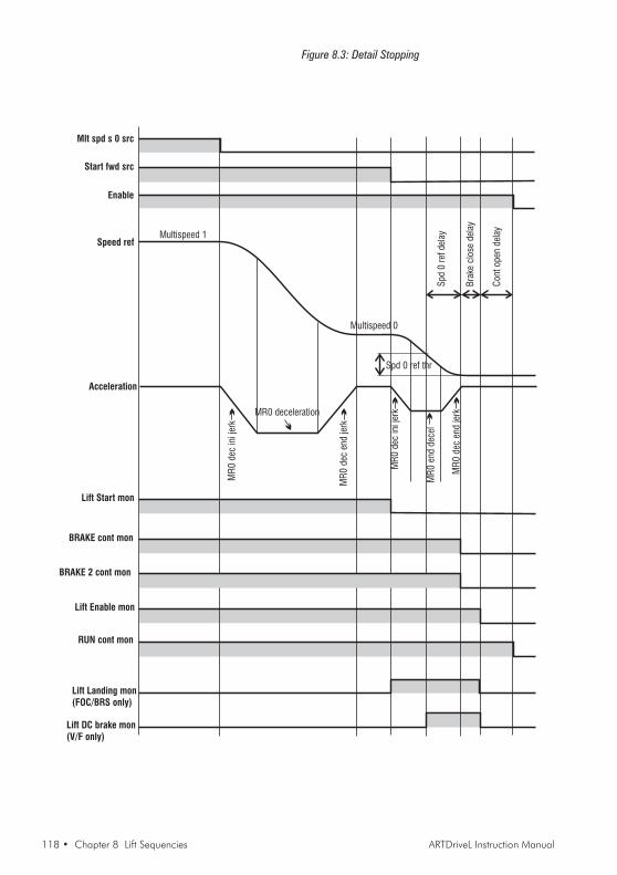
118 • Chapter 8 Lift Sequencies ARTDriveL Instruction Manual
Figure 8.3: Detail Stopping
Con
top
ende
lay
Spd
0re
fde
lay
Start fwd src
Mlt spd s 0 src
Speed ref
RUN cont mon
Lift Enable mon
BRAKE cont mon
Lift Start mon
Enable
Bra
kecl
ose
dela
y
Lift Landing mon(FOC/BRS only)
Lift DC brake mon(V/F only)
Spd 0 ref thr
Multispeed 1
Multispeed 0
MR
0de
cin
i jer
kMR0 deceleration
Acceleration
MR
0en
dde
cel
MR
0de
cen
dje
rk
MR
0de
cen
dje
rk
MR
0de
cin
i jer
k
BRAKE 2 cont mon
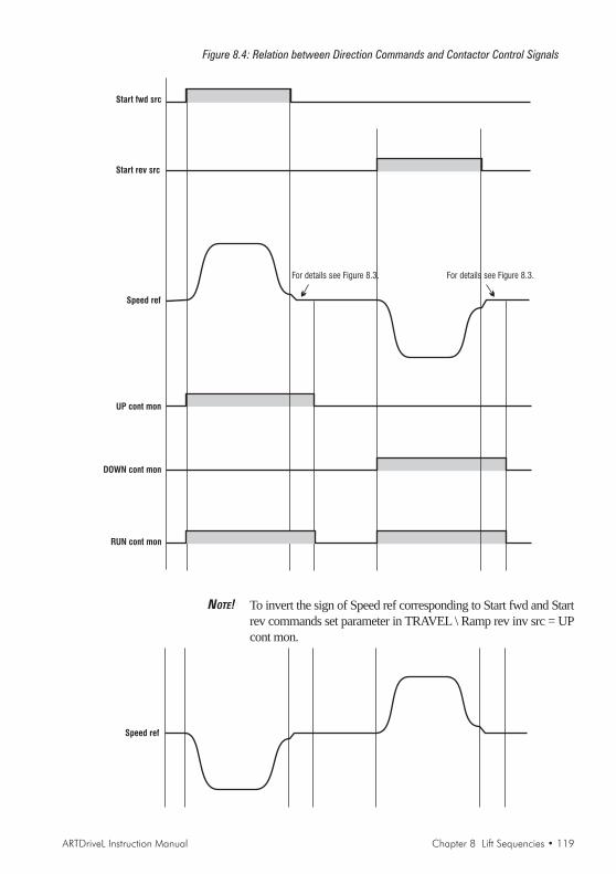
ARTDriveL Instruction Manual Chapter 8 Lift Sequencies • 119
Figure 8.4: Relation between Direction Commands and Contactor Control Signals
Start rev src
RUN cont mon
For details see Figure 8.3.
Start fwd src
DOWN cont mon
UP cont mon
For details see Figure 8.3.
Speed ref
NOTE! To invert the sign of Speed ref corresponding to Start fwd and Startrev commands set parameter in TRAVEL \ Ramp rev inv src = UPcont mon.
Speed ref
120 • Chapter 8 Lift Sequencies ARTDriveL Instruction Manual
NOTE:

ARTDriveL Instruction Manual Chapter 9 Parameter • 121
Chapter 9 - Parameter
9.1 Parameter Legend
TRATRATRATRATRAVELVELVELVELVEL
TRAVEL / DC braking1836 DCbrake cmd src N/A RWS IPA 7125List 3 PIN V-F-S-B
IPA 7125 Lift DC Brake mon = DefaultIt allows to select the origin of the signal to command DC braking function(refer to signals List 3 of Pick List manual)
Point type
AB
A can to be > F float type> P float type> D digital type (Integer with 16 bits)
B can to be > P parameter> V variable> K constant
PIN The parameter type is enumerative.It has, therefore, a list of possible values (for example it is a source)
Validity DB
The reading keys are:F Field orientedS SensorlessV V/fA Autotuning (Setup mode)B Brushless
IPA Description [Unit] Access Default Min Max Format Reg. Mode
Parameter number
Parameter unit of measure
Access mode parameter R read only W write type S saved in flash Z accessible with drive disabled
Parameter valueD.Size value determined by drive sizeCalc value calculated in function of other
parameterDrvVer value dependent on drive fw versionMotr value dependent on motorList X signal list
Parameter name
Main menu
2nd level
The Pick List manual is available (pdf format) on the supplied “CONF 99” cd-rom.

122 • Chapter 9 Parameter ARTDriveL Instruction Manual
9.2 Parameter Description
MONITORMONITORMONITORMONITORMONITORThis menu displays a series of variables useful to check the Drive state. The variable function is clearly explainedby the variable name.
Monitor3060 Output voltage [V] R 0.00 0.00 0.00 PV V-F-S-B
Voltage on the drive output terminals
3070 Output current [A] R 0.00 0.00 0.00 PV V-F-S-BCurrent on the drive output terminals
3080 Output frequency [Hz] R 0.00 0.00 0.00 PV V-F-S-BDrive output frequency
3090 Output power R 0.00 0.00 0.00 PV V-F-S-BDrive output power. UNIT: [kW] for AVy ... AC/AC4, [kVA] for AVy ... BR/BR4.
9405 Norm Speed [rpm] R 0.00 0.00 0.00 PV V-F-S-BSpeed of the motor
3210 Speed ref [rpm] R 0.00 0.00 0.00 PV V-F-S-BDrive speed reference
3200 Ramp ref [rpm] R 0.00 0.00 0.00 PV V-F-S-BDrive ramp reference
162 Enable SM mon N/A R 0 0 1 DV V-F-S-BIt shows the drive Enable state
163 Start SM mon N/A R 0 0 1 DV V-F-S-BIt shows the drive Start state0 OFF1 ON
164 FastStop SM mon N/A R 0 0 1 DV V-F-S-BIt shows the drive FastStop state0 OFF1 ON
MONITOR / I/O status4028 DI 7654321E N/A R 0 0 1 DP V-F-S-B
Standard digital inputs status, from 0 to 7; E (Enable) = Digital Input 0
4064 DO 3210 N/A R 0 0 1 DP V-F-S-BStandard digital outputs status, from 0 to 3
4057 DIX BA9876543210 N/A R 0 0 1 DP V-F-S-BExpanded digital inputs status, from 0 to 11;A = Digital InputX 10, B = Digital InputX 11 (X suffix means expanded)
4078 DOX 76543210 N/A R 0 0 1 DP V-F-S-BExpanded digital outputs status, from 0 to 7 (X suffix means expanded)
IPA Description [Unit] Access Default Min Max Format Reg. Mode
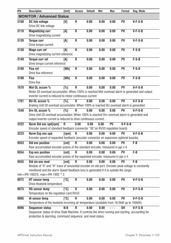
ARTDriveL Instruction Manual Chapter 9 Parameter • 123
IPA Description [Unit] Access Default Min Max Format Reg. Mode
MONITOR / Advanced Status3100 DC link voltage [V] R 0.00 0.00 0.00 PV V-F-S-B
Drive DC link voltage
3110 Magnetizing curr [A] R 0.00 0.00 0.00 PV V-F-S-BDrive magnetizing current
3120 Torque curr [A] R 0.00 0.00 0.00 PV V-F-S-BDrive torque current
3130 Magn curr ref [A] R 0.00 0.00 0.00 PV F-S-BDrive magnetizing current reference
3140 Torque curr ref [A] R 0.00 0.00 0.00 PV F-S-BDrive torque current reference
3180 Flux ref [Wb] R 0.00 0.00 0.00 PV F-S-BDrive flux reference
3190 Flux [Wb] R 0.00 0.00 0.00 PV F-S-BDrive flux
1670 Mot OL accum % [%] R 0.00 0.00 0.00 PV V-F-S-BMotor I2t overload accumulator. When 100% is reached Mot overload alarm is generated and outputinverter current is reduced to motor continuous current
1781 BU OL accum % [%] R 0.00 0.00 0.00 PV V-F-S-BBraking Unit I2t overload accumulator. When 100% is reached BU overload alarm is generated.
1540 Drv OL accum % [%] R 0.00 0.00 0.00 PV V-F-S-BDrive Unit I2t overload accumulator. When 100% is reached Drv overload alarm is generated andoutput inverter current is reduced to drive continuous current. .
3222 Norm Std enc spd[rpm] R 0.00 0.00 0.00 PV V-F-S-BEncoder speed of standard feedback (connector “XE”on RV33 regulation board)
3223 Norm Exp enc spd [rpm] R 0.00 0.00 0.00 PV V-F-S-BEncoder speed of expanded feedback (encoder connector on expansion optional boards)
9553 Std enc position [cnt] R 0.00 0.00 0.00 PV F-BRaw accumulated encoder pulses of the standard encoder, measured in ppr x 4
9554 Exp enc position [cnt] R 0.00 0.00 0.00 PV F-BRaw accumulated encoder pulses of the expanded encoder, measured in ppr x 4
9555 Std sin enc mod [cnt] R 0.00 0.00 0.00 PV F-BModule of “A” and “B” trace of sinusoidal encoder on std port. Encoder peak voltage is constantlymonitored and the alarm Speed feedback loss is generated if it is outside the range:
min=IPA 1902/5, max=IPA 1902 * 2.
9072 HT sensor temp [°C] R 0.00 0.00 0.00 PV V-F-S-BDrive Heatsink temperature
9073 RG sensor temp [°C] R 0.00 0.00 0.00 PV V-F-S-BTemperature on the regulation card RV33
9095 IA sensor temp [°C] R 0.00 0.00 0.00 PV V-F-S-BTemperature of the heatsink incoming air temperature (available from 18.5kW up to 160kW)
9090 Sequencer status N/A R 0.00 0.00 - - - DV V-F-S-BSequencer status of drive State Machine. It controls the drive running and starting, accounting forprotection & alarming, command sequence, and reset status.

124 • Chapter 9 Parameter ARTDriveL Instruction Manual
IPA Description [Unit] Access Default Min Max Format Reg. Mode
State Sequencer status1 Magnetization running2 Magnetization completed, Stop3 Star t4 Fast stop, Stop5 Fast stop, Start9 No alarm, drive is ready to accept all commands10 Magnetization running and Start command already present12 Alarm active16 Alarm not active, waiting for reset
3230 CPU1 runtime [%] R 0.00 0.00 0.00 PV V-F-S-BTime needed by the CPU1 (microprocessor)
3240 CPU2 runtime [%] R 0.00 0.00 0.00 PP V-F-S-BTime needed by the CPU2 (microprocessor)
MONITOR - Drive ID Status1460 Drive cont curr [A] RW CALC 0.00 0.00 FK V-F-S-B
Drive maximum continuos current rating; its default value depends by the drive size and applicablederating factors.
114 Drive size N/A R D.Size 0 20 DK V-F-S-BDrive size rating in kW (ULN = 400VAC, IEC 146 Class 1) of Hp (ULN = 460VAC, IEC 146 Class 2):0 0.75 kW - 0.75 Hp1 1.5 kW -1.5 Hp2 2.2 kW - 2.0 Hp3 3.0 kW - 3.0 Hp4 4.0 kW - 5.0 Hp5 5.5 kW - 7.5 Hp6 7.5 kW - 10 Hp7 11 kW - 15 Hp8 15 kW - 20 Hp9 22 kW - 25 Hp10 30 kW - 30 Hp11 37 kW - 40 Hp12 45 kW - 50 Hp13 55 kW - 60 Hp14 75 kW - 75 Hp15 90 kW - 100 Hp16 110 kW - 125 Hp17 132 kW - 150 Hp18 160 kW - 200 Hp19 250 kW - 300 Hp20 315 kW - 450 Hp21 18.5kW - 22.5 Hp
300 Drive type N/A R 288 0 0 DK V-F-S-B288 460V default settings for AVy ... AC/AC4289 460V default settings for AVy ... BR/BR434 400V default settings for AVy ... AC/AC435 400V default settings for AVy ... BR/BR4

ARTDriveL Instruction Manual Chapter 9 Parameter • 125
IPA Description [Unit] Access Default Min Max Format Reg. Mode
115 Drive name N/A RWS 0.00 0.00 0.00 FK V-F-S-BACDRV asynchronous firmwareACDRVM brushless drive firmware
810 Actual setup N/A R 0 0 0 DK V-F-S-BSetup motor file in use (reserved)
107 Software versionDrive software version (factory installed), example: V 3. 0. 0
110 Software type N/A R DrvVer 0 0 DV V-F-S-BSoftware type factory use
111 Software status N/A R DrvVer 0 0 DV V-F-S-BSoftware state factory use
99 Life time [hrs] R 0.00 0.00 0.00 PV V-F-S-BDrive life time accumulated with power on
98 Sys time-ddmmyy [h/m/s] R 0.00 0.00 0.00 PV V-F-S-BTime and date setting from PC configurator or serial communications.Clock is active only when the Drive is powered onNOTE! On a new regulation card the variable takes value: 00:00:00 (time) 010170 (date)
MONITOR / Alarm logThis function provides a list of last 30 drive trips or various system error messages. Togetherwith cause indications also time and data infornations is provided. Alarm logmessage is referred to “Sys time - dd mm yy” variable.
Example:01:02:36 01 02 00Undervoltage
01:02:36 time of alarm02 02 00 date of alarmUndervoltage alarm description
MONITOR / Alarm log clear?It deletes all the alarms listed in the Alarm log.

126 • Chapter 9 Parameter ARTDriveL Instruction Manual
IPA Description [Unit] Access Default Min Max Format Reg. Mode
STSTSTSTSTARTUPARTUPARTUPARTUPARTUP
STARTUP / Startup config / Enter setup modeEnter setup mode command allows the access to SETUP MODE to set drive basic parameters and motor platedata. Drive will reboot and few seconds are required. All changes and operations done in the SETUP MODE will beautomatically saved, every time the user executes exits setup mode.
SETUP MODE / Drive data380 Mains voltage [V] RW 2 0 5 DK V-F-S-B
Drive power supply voltage. Select supply voltage parameter accurately, according to actual drivesupply voltage. After changing this parameter, selftune data are initialized to default, self-tuningmust be repeated !0 230 V1 380 V2 400 V3 415 V4 440 V5 460 V
1350 Ambient temp [°C] RW 0 0 1 DK V-F-S-BDrive ambient temperature. Selecting 50°C will result in drive derating, see chapter 2.3. After changingthis parameter selftune data are initialized to default, self-tuning must be repeated !0 40°C1 50°C
170 Switching freq [kHz] RW D.Size 0 3 DK V-F-S-BDrive PWM switching frequency. Selecting higher switching frequency then default, results in drivederating, see table 2.3.4.1. Selecting lower value results in higher continuous output current.After changing this parameter, selftune data are initialized to default, self-tuning must be repeated !0 2 kHz1 4 kHz2 8 kHz3 16 kHz4 12 kHz
1880 Spd ref/fbk res [rpm] RW 1 0 5 DK V-F-S-BResolution of the speed references referred to the maximum process speed (1885. “Fullscale speed” parameter). After changing this parameter, selftune data are initialized to default,self-tuning must be repeated !0 0.125 rpm -> 2048 rpm maximum process speed1 0.250 rpm -> 4096 rpm maximum process speed2 0.500 rpm -> 8192 rpm maximum process speed3 1.000 rpm -> 16384 rpm maximum process speed4 0.03125 rpm -> 512 rpm maximum process speed
SETUP MODE / Motor data (for AVy . AC series)670 Rated voltage [V] RW D.Size Calc Calc FK V-F-S-B
Motor rated voltage
680 Rated frequency [Hz] RW D.Size Calc Calc FK V-F-SMotor rated frequency
690 Rated current [A] RW D.Size Calc Calc FK V-F-S-BMotor rated current
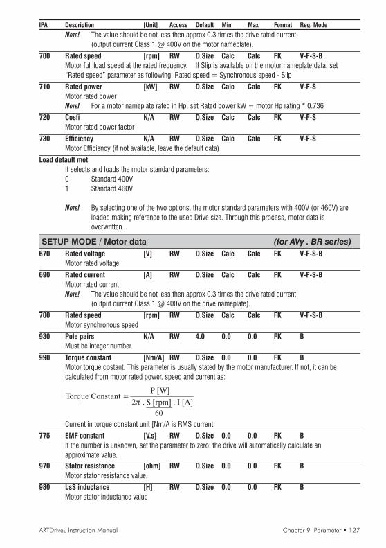
ARTDriveL Instruction Manual Chapter 9 Parameter • 127
IPA Description [Unit] Access Default Min Max Format Reg. Mode
NOTE! The value should be not less then approx 0.3 times the drive rated current(output current Class 1 @ 400V on the motor nameplate).
700 Rated speed [rpm] RW D.Size Calc Calc FK V-F-S-BMotor full load speed at the rated frequency. If Slip is available on the motor nameplate data, set“Rated speed” parameter as following: Rated speed = Synchronous speed - Slip
710 Rated power [kW] RW D.Size Calc Calc FK V-F-SMotor rated powerNOTE! For a motor nameplate rated in Hp, set Rated power kW = motor Hp rating * 0.736
720 Cosfi N/A RW D.Size Calc Calc FK V-F-SMotor rated power factor
730 Efficiency N/A RW D.Size Calc Calc FK V-F-SMotor Efficiency (if not available, leave the default data)
Load default motIt selects and loads the motor standard parameters:0 Standard 400V1 Standard 460V
NOTE! By selecting one of the two options, the motor standard parameters with 400V (or 460V) areloaded making reference to the used Drive size. Through this process, motor data isoverwritten.
SETUP MODE / Motor data (for AVy . BR series)670 Rated voltage [V] RW D.Size Calc Calc FK V-F-S-B
Motor rated voltage
690 Rated current [A] RW D.Size Calc Calc FK V-F-S-BMotor rated currentNOTE! The value should be not less then approx 0.3 times the drive rated current
(output current Class 1 @ 400V on the drive nameplate).
700 Rated speed [rpm] RW D.Size Calc Calc FK V-F-S-BMotor synchronous speed
930 Pole pairs N/A RW 4.0 0.0 0.0 FK BMust be integer number.
990 Torque constant [Nm/A] RW D.Size 0.0 0.0 FK BMotor torque costant. This parameter is usually stated by the motor manufacturer. If not, it can becalculated from motor rated power, speed and current as:
Torque Constant =P [W]
2 . S [rpm] . I [A]
60
Current in torque constant unit [Nm/A is RMS current.
775 EMF constant [V.s] RW D.Size 0.0 0.0 FK BIf the number is unknown, set the parameter to zero: the drive will automatically calculate anapproximate value.
970 Stator resistance [ohm] RW D.Size 0.0 0.0 FK BMotor stator resistance value.
980 LsS inductance [H] RW D.Size 0.0 0.0 FK BMotor stator inductance value

128 • Chapter 9 Parameter ARTDriveL Instruction Manual
IPA Description [Unit] Access Default Min Max Format Reg. ModeNOTE! If “EMF costant”, “Stator resistance” and “LsSinductance” values are unknown, set them tozero before running the current self-tuning procedure.
Load default motIt selects and loads the motor standard parameters:0 Set 01 Set 1NOTE! By this selection, the motor standard parameters with “Set 1” (or “Set 2”) are loaded makingreference to the used Drive size. Through this process, motor data is overwritten.
SETUP MODE / AutotuneComplete still (for AVy . AC series)
Complete self-tuning of current and flux loop with a stopped rotor“Start ?” enable data detection command (12 drive terminal must be cycle to +24Vdc)
Complete rot (for AVy . AC series)Complete self -tuning of current and flux loop with a moving rotor“Start ?” enable data detection command (12 drive terminal must be cycle to +24Vdc)
CurrReg (for AVy . AC and BR series)Self-tuning of current loop only with stopped motor“Start ?” enable data detection command (12 drive terminal must be cycle to +24Vdc)
FluxReg rot (for AVy . AC series)Self-tuning of flux loop with a moving rotor only“Start ?” enable data detection command (12 drive terminal must be cycle to +24Vdc)
FluxReg still (for AVy . AC series)Self-tuning of flux loop with a stopped rotor only“Start ?” enable data detection command (12 drive terminal must be cycle to +24Vdc)
SETUP MODE / Autotune / Results2780 Measured Rs [ohm] RW Calc Calc Calc FK V-F-S-B
Value of the phase resistance detected on the stator of the motor
2790 Measured DTL [V] RW Calc 0 Calc FK V-F-S-BIGBT dead time limit
2800 Measured DTS [ohm] RW Calc 0 Calc FK V-F-S-BIGBT dead time slope
2810 Measured LsSigma [H] RW Calc Calc Calc FK V-F-S-BValue of inductance detected on the stator of the motor
2820 Measured Rr [ohm] RW Calc Calc Calc FK V-F-SValue of resistance detected on the rotor of the motor
2830 Measured Rr2 [ohm] RW Calc Calc Calc FK V-F-SValue of resistance 2 detected on the rotor of the motor
2840 Measured P1 flux N/A RW Calc 0.00 1.000 FK V-F-SP1 coefficient of the Flux curve measured
2850 Measured P2 flux N/A RW Calc 3 18 FK V-F-SP2 coefficient of the Flux curve measured
2860 Measured P3 flux N/A RW Calc 0.00 1.00 FK V-F-SP3 coefficient of the Flux curve measured
2870 Measured Im Nom [A] RW Calc 0.00 0.00 FK V-F-SValue of the rated magnetizing current

ARTDriveL Instruction Manual Chapter 9 Parameter • 129
IPA Description [Unit] Access Default Min Max Format Reg. Mode2880 Measured Im Max [A] RW Calc 0.00 0.00 FK V-F-S
Value of the maximum magnetizing current
2890 Measured Flux Nom [Wb] RW Calc 0.00 0.00 FK V-F-SValue of the rated Flux
2900 Measured Flux Max [Wb] RW Calc 0.00 0.00 FK V-F-SValue of the maximumFlux
STARTUP / Startup config / Load setupLoad setup
Load setup command is required to load all SETUP MODE settings into the regulation mode selected.Entering this parameter, on the display will appear:
Load setup?Yes -> Ent No -> Esc
• Press Enter to load the SETUP MODE settings.• Press Escape if you do not want to load the SETUP MODE settings
NOTE! The operation is required for every Regulation mode (V, F, S and B)It is also required for every new setting made in the SETUP MODE.
If any changes / settings in Motor data and Drive data are detected, Load setup command ispresented automatically to the user, respond Yes to load data.
STARTUP / Startup config / Mechanical data1015 Travel units sel N/A RWZ 0 0 1 DK V-F-S-B
0 Revolutions1 MillimetersIt determines the units of “TRAVEL / Speed profile” and “TRAVEL / Ramp profile” menu parameters:Revolutions = rpm, rpm/s and rpm/s2 - Millimeters = mm/s, mm/s2 and mm/s3
1002 Gearbox ratio N/A RWZ 35 1 100 FK V-F-S-BRatio between motor shaft speed and pulley speed. Eventual roping ratio must also be included.
1003 Pulley diameter [mm] RWZ 500 100 2000 FK V-F-S-BDiameter of the pulley
1885 Full scale speed [rpm] RW 1500 Calc Calc PV V-F-S-BIt defines the 100% of the application speed referenced. The absolute speed handling range is ± 200%Full scale speed.For lift application set this parameter to maximum allowed motor speed, typically rated speed of themotor. This parameter will also set the limit on all multispeed values IPA 7060 - 7067.
STARTUP / Startup config / Weights1004 Car weight [kg] RWZ 0.00 0.00 0.00 FK V-F-S-B
Weight of the Lift car
1005 Counter weight [kg] RWZ 0.00 0.00 0.00 FK V-F-S-BWeight of the counter mass to achieve balanced system
1006 Load weight [kg] RWZ 0.00 0.00 0.00 FK V-F-S-BMaximum weight of Lift load (total persons weight)
1007 Rope weight [kg] RWZ 0.00 0.00 0.00 FK V-F-S-BTotal weight of Rope
1011 Motor inertia [kgm2] RWZ 0.000 0.000 0.000 FK V-F-S-BInertia of the motor, refer to motor manufacturer (if it is not available, leave to default)
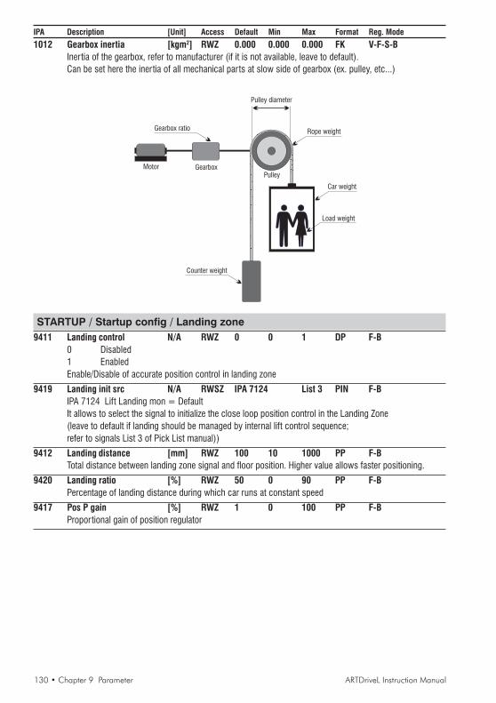
130 • Chapter 9 Parameter ARTDriveL Instruction Manual
IPA Description [Unit] Access Default Min Max Format Reg. Mode
1012 Gearbox inertia [kgm2] RWZ 0.000 0.000 0.000 FK V-F-S-BInertia of the gearbox, refer to manufacturer (if it is not available, leave to default).Can be set here the inertia of all mechanical parts at slow side of gearbox (ex. pulley, etc...)
PulleyMotor Gearbox
Pulley diameter
Rope weight
Car weight
Load weight
Counter weight
Gearbox ratio
STARTUP / Startup config / Landing zone9411 Landing control N/A RWZ 0 0 1 DP F-B
0 Disabled1 EnabledEnable/Disable of accurate position control in landing zone
9419 Landing init src N/A RWSZ IPA 7124 List 3 PIN F-BIPA 7124 Lift Landing mon = DefaultIt allows to select the signal to initialize the close loop position control in the Landing Zone(leave to default if landing should be managed by internal lift control sequence;refer to signals List 3 of Pick List manual))
9412 Landing distance [mm] RWZ 100 10 1000 PP F-BTotal distance between landing zone signal and floor position. Higher value allows faster positioning.
9420 Landing ratio [%] RWZ 50 0 90 PP F-BPercentage of landing distance during which car runs at constant speed
9417 Pos P gain [%] RWZ 1 0 100 PP F-BProportional gain of position regulator
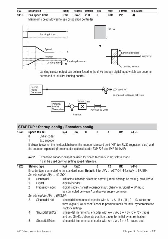
ARTDriveL Instruction Manual Chapter 9 Parameter • 131
IPA Description [Unit] Access Default Min Max Format Reg. Mode
9410 Pos speed limit [rpm] RWZ 200 0 Calc PP F-BMaximum speed allowed to use by position controller
Landing ratio
t
0
Landing distance
1
Position
Speed
Landing init src
Landing distance
Floor level
Landing sensor
Lift car
Landing sensor output can be interfaced to the drive through digital input which can becomecommand to initialize landing control.
SpeedProfileGenerator
PositionProfileGeneration -
+
+
+
Position
Pos P Gain
Pos Speed Limit
LZ speed ref
connected to Speed ref 1 src
STARTUP / Startup config / Encoders config1940 Speed fbk sel N/A RW 0 0 1 DV V-F-B
0 Std encoder1 Exp encoderIt allows to switch the feedback between the encoder standard port “XE” (on RV33 regulation card) andthe encoder expanded (from encoder optional cards: EXP-F2E and EXP-D14A4F)
NOTE! Expansion encoder cannot be used for speed feedback in Brushless mode.It can be used only for setting speed reference.
1925 Std enc type N/A RWZ 0 12 DK V-F-BEncoder type connected to the standard input. Default: 1 for AVy ... AC/AC4, 4 for AVy ... BR/BR4Set allowed for AVy ... AC/AC4:0 Sinusoidal sinusoidal encoder, select the correct jumper settings on the reg. card, RV331 Digital digital encoder2 Frequency input digital single channel frequency input: channel A. Signal +5V must
be connected between A and power supply common.Set allowed for AVy ... BR/BR4:3 Sinusoidal Hall sinusoidal incremental encoder with A+ / A-, B+ / B-, C+ /C traces and
three digital “Hall sensor” absolute position traces for initial synchronisation(factory setting)
4 Sinusoidal SinCos sinusoidal incremental encoder with A+ / A-, B+ / B-, C+ /C- tracesand two Sin/Cos absolute position traces for initial synchronisation
5 Sinusoidal Extern sinusoidal incremental encoder with A+ / A-, B+ / B- traces and

132 • Chapter 9 Parameter ARTDriveL Instruction Manual
IPA Description [Unit] Access Default Min Max Format Reg. Modeabsolute position information through SSI serial interface for initialsynchronisation (requires APC card)
6 Digital Hall digital incremental encoder with A+ / A-, B+ / B-, C+ / C- traces andthree digital “Hall sensor” absolute position traces for initial synchronisation(factory setting)
7 DigitalExtern digital incremental encoder with A+ / A-, B+ / B- traces and absoluteposition information through SSI serial interface for initial synchronisation
(requires APC card)8 SinCos Sin / Cos absolute position traces for initial synchronisation, incremental
information is not used.9 Resolver resolver using option cards: EXP-RES (refer its manual for jumpers 0
configurations)10 Sinusoidal Hiperface absolute encoder with Hiperface protocol (from software rel. 3.300)11 Sinusoidal Intern sinusoidal incremental encoder with A+/A-,B+/B-, C+/C- traces,
absolute position traces are not necessary because phasing is performedautomatically at every start (from software rel. 3.500)
12 Digital Intern digital incremental encoder with A+/A-,B+/B-, C+/C- traces,absolute position traces are not necessary because phasing is performed
automatically at every start (from software rel. 3.500)
1890 Std enc pulses [ppr] RWZ 1024 Calc Calc FK V-F-S-BEncoder pulses per revolution (ppr) value of the standard input.For brushless motors it is possible to use only the following values: 512, 1024, 2048, 4096, 8192.
1931 Std dig enc mode N/A RWZ 0 0 1 DP V-F-S-B0 FP mode frequency and period measuring1 F mode frequency measuringMeasuring method of the digital encoder speed connected to the standard input
1927 Std enc supply N/A RWZ 0 0 3 DP V-F-S-B0 5.41 / 8.16 V1 5.68 / 8.62 V2 5.91 / 9.00 V3 6.16 / 9.46 VSelection between 5V / 8V range is done through dip-switch S28.Power supply voltage of the standard Encoder input. Increse this value in case of long encoder cable.
1902 Std sin enc Vp [V] RW 0.5 0 1.5 FK V-F-BPeak voltage value of the sinusoidal encoder connected to the standard input
1300 Std enc cnt dir N/A RWSZ 0 0 1 DP V-F-S-B0 Not inverted1 InvertedSelection of standard encoder counting direction. It allows to change sign of measured speed, it isequivalent of swaping encoder channels AA- <-> BB-.
1926 Exp enc type N/A RW 1 1 2 DK V-F-BEncoder type connected to the expanded input1 Digital digital encoder2 Frequency input digital single channel frequency input: channel A. Signal +5V must
be connected between A and power supply common.
NOTE! For brushless motors expanded encoder cannot be used for speed feddback.It can be used only for setting speed reference.
ARTDriveL Instruction Manual Chapter 9 Parameter • 133
IPA Description [Unit] Access Default Min Max Format Reg. Mode
1900 Exp enc pulses [ppr] RWZ 1024 Calc Calc FK V-F-BEncoder pulses per revolution (ppr) value of the expanded input.
1301 Exp enc cnt dir N/A RWSZ 0 0 1 DP V-F-B0 Not inverted1 InvertedSelection of expansion encoder counting direction. It allows to change sign of measured speed, it isequivalent of swaping encoder channels AA- <-> BB-.
STARTUP / Startup config / Encoders config / Rep/Sim encoder1962 Rep/Sim enc sel N/A RWZ 0 0 1 DK V-F
Selection of the encoder to be repeated using the optional card EXP-F2E.0 Repeat std enc repeat standard encoder1 Repeat exp enc repeat expanded encoder2 Simulate std simulate digital incremental encoder in case of SinCos or Resolver
selections as feedback devices in Std enc type parameter.
1952 Sim enc pulses N/A RWZ 1024 1 Calc FK BSimulated encoder pulses per revolution (ppr) value (factory setting = 1024 ppr)
STARTUP / Startup config / Encoders config / Index storing9550 Index storing en N/A RWSZ 0 0 3 DV F-B
Index storing function.The encoder counts can be latched allowing the user to determine the position of the encoder relative toan absolute position.
0 Off1 Storing enabled enables the capturing of the encoder count as described by the
setting of the control word. The control word is the value of“Int IS ctrl” or the word selected by “IS ctrl src”
2 Control std enc it constantly reads all the generated pulses on the std encoder3 Control exp enc it constantly reads all the generated pulses on the exp encoder
9551 Int IS ctrl N/A RWS 0 0 0X0000 DV F-BFixed programming at Index Storing Function according to following table.
9557 IS ctrl src N/A RWSZ IPA 9551 List 39 PIN F-BIPA 9551 Int IS ctrl = DefaultIt allows to select the origin of the signal for “Index storing function” command.For example a SBI word or DGFC word (refer to signals List 39 of Pick List manual)
NOTE! Digital inputs 6 and 7 (terminals 38 and 39) are dedicated to the use of the “Index Qualifier”(home position switch) when Index storing is enabled.
In the next table are showed the values of IS ctrl src from SBI word, DGFC word or Int IS ctrl if:IS ctrl src = Int IS ctrl
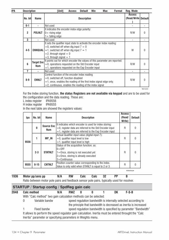
134 • Chapter 9 Parameter ARTDriveL Instruction Manual
IPA Description [Unit] Access Default Min Max Format Reg. Mode
No. bit Name Description
Access
(Read/Write
)Default
0-1 - Not used - -
It indicates the encoder index edge polarity:0= rising edge1= falling edge
3 - Not used - -It sets the qualifier input state to activate the encoder index reading:=0, switched off when dig.input 7 = 0
=1, switched off when dig.input 7 = 1=2, through signal = 0
=3, through signal = 1It points out for which encoder the values of this parameter are reported:=0, operations requested on the Std Encoder input
=1, operations requested on the Exp Encoder input
7 - Not used - -Control function of the encoder index reading
=0, switched off, function disabled
=1, once, enables the reading of the first index signal edge only.=2, continuous, enables the reading of the index signal
TAV13241
R/W 0
8-9 R/W 0ENNLT
2
4-5
6
POLNLT
ENNQUAL
Target Enc
Num
0R/W
W 0
For the Index storing function, the status Registers are not available via keypad and are to be used forthe configuration and the data reading. These are:L index register IPA9556H index register IPA9555In the next table are showed the registers values:
Ipa No. bit Name Description
Access
(Read/
Write)Default
It indicates which encoder is used for index storing:=0, register data are referred to the Std Encoder input
=1, register data are referred to the Exp Encoder input
Actual Qualifier input value (digital input 7):=0, qualifier input level is low=1, qualifier input level is high
Status of the acquisition function; as:0=OFF1=Once, storing is not executed yet
2=Once, storing is already executed
3=Continuous
Position counter value corresponding to the index.Value is only valid when STANLT is equal to 2 or 3
indexstorpar
Source Enc
Num
9556
9555
0
1
2-3
0-15
MP_IN
STATNLT
CNTNLT
R
R
0
0
0
0
R
R
1936 Motor pp/sens pp N/A RW Calc Calc 32 PP BRatio between motor pole pairs and feedback sensor pole pairs, typically used for resolver.
STARTUP / Startup config / SpdReg gain calc2048 Calc method N/A RWZ 0 0 1 DK F-S-B
With “Calc method” two gain calculation methods can be selected:0 Variable bandw speed regulation bandwidth is internally selected according to
the principle that bandwidth is decreased as inertia is increased1 Fixed bandw speed regulation bandwidth is specified by parameter “Bandwidth”It allows to perform the speed regulator gain calculation. Inertia must be entered throught the “CalcInertia” parameter or specifying parameters in Weights menu.
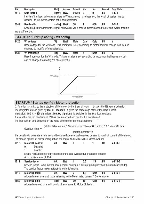
ARTDriveL Instruction Manual Chapter 9 Parameter • 135
IPA Description [Unit] Access Default Min Max Format Reg. Mode
2610 Calc Inertia [kgm2] RWZ D.Size 0 0 FK F-S-BInertia of the load. When parameters in Weights menu have been set, the result of system inertiareferred to the motor shaft is set in this parameter.
2049 Bandwidth [rad/s] RWZ 50 1 400 FK F-S-BSpeed regulator bandwidth. Higher bandwidth value makes motor respond faster and overall result is
more stiff control.
STARTUP / Startup config / V/f config3420 V/f voltage [V] RWZ Motr Calc Calc FK V
Base voltage for the V/f mode. This parameter is set according to motor nominal voltage, but can bechanged to modify V/f characteristic.
3430 V/f frequency [Hz] RWZ Motr 5 Calc FK VBase frequency for the V/f mode. This parameter is set according to motor nominal frequency, butcan be changed to modify V/f characteristic.
V
V/f frequency
f
V/f voltage
STARTUP / Startup config / Motor protectionI2t function is similar to the protection of the motor by the thermal relay. It states the I2t typical behavior.The integrator state is given by Mot OL accum %, it gives the percentage state of the Rms currentintegration, 100 % = I2t alarm level. Mot OL trip signal is available in the pick-list selections.It states that the trip condition of I2t has been reached and overload is not allowed.The intervention time depends on the value of the motor current as follows:
(Motor Rated current * Service factor * Motor OL factor )^2* Motor OL timeOverload time = ——————————————————————————————
(Motor current)^2It is possible to generate an alarm condition or reduce eventual overload current to nominal current of the motor.For various options of alarm configuration see menu ALARM CONFIG / Motor overload.1612 Motor OL control N/A RW 0 0 1 DK V-F-S-B
0 Disabled1 EnabledEnable / disable motor current limit control and overload I2t protection function(from software rel. 3.300).
1611 Service factor N/A RW 1 0.5 1.5 FK V-F-S-BService factor. Some motors have a motor continuous current (Ic) higher than the rated current (In).The service factor makes reference to the Ic/In ratio.
1610 Motor OL factor N/A RW 2 1.2 Calc FK V-F-S-BAllowed motor overload factor referring to the Motor rated current * Service factor
1650 Motor OL time [sec] RW 30 10 Calc FK V-F-S-BAllowed overload time with overload level equal to Motor OL factor.

136 • Chapter 9 Parameter ARTDriveL Instruction Manual
IPA Description [Unit] Access Default Min Max Format Reg. Mode
[%]
t [sec](1) 100
150
(2) 200
250
300
0 15 30(3)
45
(1) Rated current • Service factor = 100%(2) Motor OL factor(3) Motor OL time
STARTUP / Startup config / BU protectionThe function protects braking resistor by monitoring current in the resistor according to I2tcharacteristic. When the protection becomes active, it is possible to generate an alarm condition.According to the different cases it is possible to use the device internal IGBT (or external braking unit).
1700 BU control N/A RWZ 1 0 2 DP V-F-S-B0 Off Function disabled1 Internal Enable Braking Unit internal device (Default)2 External Enable Braking Unit external BUy deviceThe parameter enables the Braking Unit function.
1740 BU resistance [ohm] RWZ D.Size Calc 10000 FK V-F-S-BBraking Unit resistance value, mounted optional on the power section terminals or external (C & BR1)
1710 BU res cont pwr [kW] RWZ D.Size 0 0 FK V-F-S-BBraking Unit resistance continuous power
1720 BU res OL time [sec] RWZ D.Size 1 1000 FK V-F-S-BResistance allowed overload time referring to the overload power. The control of the external braking unitand of the resistance I2t protection is independent of BU type (BU digital output command, is available,
on the regulation card terminals ).
1730 BU res OL factor N/A RWZ D.Size 1.2 20 FK V-F-S-BAllowed overload factor referring to the overload power of the braking resistance. Overload factor =overload Power/ rated Power
t [sec](1)
(2)
0 (3)
(1) BU res cont power(2) BU res OL factor(3) BU res OL time

ARTDriveL Instruction Manual Chapter 9 Parameter • 137
IPA Description [Unit] Access Default Min Max Format Reg. Mode
STARTUP / Startup config / Load default ?Load default ?
Drive reset with default parameter values in the selected regulation mode only.Each regulation mode has its own “Load default ?” command.NOTE! “Load default ?” command does not reset SETUP MODE with default parameter values; Drive,
Motor data and Autotune values are mantained.Use Save config command to save default parameter values such that are preserved for next power up.
STARTUP / Startup config / Load saved ?Load saved ?
Reload of the last saved database selected.
STARTUP / Regulation mode100 Regulation mode N/A R 0 0 5 DK V-F-S-B
It allows to select the desired regulation mode. When the Regulation mode parameter is selected, theactive regulation mode is displayed; in order to change it to a new mode press “Enter”; Select new modewill be displayed, then scroll the list:0 V/f control1 Field oriented2 Sensorless3 Setup mode (asynchronous motors)4 Brushless5 Setup mode (brushless motors)After new regulation mode is selected, it is possible to copy (transfer) parameters from previousregulation mode. This operation is convenient if drive has been parametrized in previous regulation mode(from software rel. 3.500).NOTE! Appropriate firmware is required using the drive in Brushless mode
STARTUP / Import recipeIn recipe user can store its configuration of parameters for a given application. By re-calling appropriate recipe fileall the necessary application parameters are set by a single command. Recipe files must be filled with parametersin the factory (please contact drive manufacturer). Available are 7 recipe files that are empty in defaultconfiguration. Only parameters outside STARTUP menu can be put to recipe files.
Select recipe:1 User 12 User 23 User 34 User 45 User 56 User 67 User 7
STARTUP / Save config ?AVyL drive allows two different commands to save the parameters modified in the regulation mode selected:
• by STARTUP menu, “Save Config?” command• by all other menus, “SAVE PARAMETERS” command
Any changes made in STARTUP menu require “Save Config?” command, which saves all entire regulation modeselected. It is recommended every time the user made any changes into STARTUP menu.“SAVE PARAMETERS” command saves all the changes made out of STARTUP menu only.When on the keypad display appears blinking message “Use Save Config”, use “Save Config?” command.

138 • Chapter 9 Parameter ARTDriveL Instruction Manual
IPA Description [Unit] Access Default Min Max Format Reg. Mode
TRATRATRATRATRAVELVELVELVELVEL
TRAVEL / Speed profileThe parameters unit is defined by IPA 1015 in “STARTUP / Startup config / Mechanical data” menu, changing theIPA 1015 setting from [0] Revolutions (default) to [1] Millimeters, the units in this menu change as follows:[rpm] becomes [mm/s], [rpm/s] becomes [mm/s2], [rpm/s2] becomes [mm/s3].7110 Smooth start spd [rpm] RWS 0 Calc Calc PP V-F-S-BSmooth start speed is selected automatically after start command independently from multispeed value. Durationof this special speed depends on Smooth start dly parameter. If this parameter is zero, Smooth start spd is notselected and multispeed values prevails. Smooth start speed can be used to optimise feeling at starting in sometypes of installations.
Speed ref
Smooth start dly
1
0
Lift start mon
Time
Smooth start spd
NOTE! “Smooth start dly” can be set in TRAVEL / Lift sequence menu.
7060 Multi speed 0 [rpm] RWS 0 Calc Calc PV V-F-S-BSpeed 0 value
7061 Multi speed 1 [rpm] RWS 0 Calc Calc PP V-F-S-BSpeed 1 value
7062 Multi speed 2 [rpm] RWS 0 Calc Calc PP V-F-S-BSpeed 2 value
7063 Multi speed 3 [rpm] RWS 0 Calc Calc PP V-F-S-BSpeed 3 value
7064 Multi speed 4 [rpm] RWS 0 Calc Calc PP V-F-S-BSpeed 4 value
7065 Multi speed 5 [rpm] RWS 0 Calc Calc PP V-F-S-BSpeed 5 value
7066 Multi speed 6 [rpm] RWS 0 Calc Calc PP V-F-S-BSpeed 6 value
7067 Multi speed 7 [rpm] RWS 0 Calc Calc PP V-F-S-BSpeed 7 value
7134 Max linear speed [mm/s] R Calc 0 0 FK V-F-S-B
TRAVEL / Ramp profileThe parameters unit is defined by IPA 1015 in “STARTUP / Startup config / Mechanical data” menu, changing the

ARTDriveL Instruction Manual Chapter 9 Parameter • 139
IPA Description [Unit] Access Default Min Max Format Reg. ModeIPA 1015 setting from [0] Revolutions (default) to [1] Millimeters, the units in this menu change as follows:[rpm] becomes [mm/s], [rpm/s] becomes [mm/s2], [rpm/s2] becomes [mm/s3].Two different sets of ramp profiles (MRO ... and MR1 ...) are available; the selection is done by parameterMlt ramp sel src (IPA 8090) into “TRAVEL / Lift sequence” menu. Default is MRO ... .
Speed ref
Multispeed
MR0 acc ini jerk
MR0 acceleration
MR0 acc end jerk
Speed refMultispeed
Multispeed
MR0 dec ini jerk MR0 deceleration
MR0 dec end jerkAcceleration
MR0 end decel
Acceleration
8046 MR0 acc ini jerk [rpm/s2] RWS 1000 0.349 750*100 PP V-F-S-BAcceleration initial jerk, set 0
8040 MR0 acceleration [rpm/s] RWS 500 1 1.5*106 PP V-F-S-BAcceleration ramp, set 0
8041 MR0 acc end jerk [rpm/s2] RWS 1000 0.349 750*106 PP V-F-S-BAcceleration end jerk, set 0
8047 MR0 dec ini jerk [rpm/s2] RWS 1000 0.349 750*106 PP V-F-S-BDeceleration initial jerk, set 0
8042 MR0 deceleration [rpm/s] RWS 500 1 1.5*106 PP V-F-S-BDeceleration ramp, set 0
8043 MR0 dec end jerk [rpm/s2] RWS 1000 0.349 750*106 PP V-F-S-BDeceleration end jerk, set 0
8044 MR0 end decel [rpm/s] RWS 1000 1 1.5*106 PP V-F-S-BFinal deceleration slope corresponding to removal of START command.
8056 MR1 acc ini jerk [rpm/s2] RWS 1000 0.349 750*106 PP V-F-S-BAcceleration initial jerk, set 1
8050 MR1 acceleration [rpm/s] RWS 500 1 1.5*106 PP V-F-S-BAcceleration ramp, set 1
8051 MR1 acc end jerk [rpm/s2] RWS 1000 0.349 750*106 PP V-F-S-BAcceleration end jerk, set 1
140 • Chapter 9 Parameter ARTDriveL Instruction Manual
IPA Description [Unit] Access Default Min Max Format Reg. Mode
8057 MR1 dec ini jerk [rpm/s2] RWS 1000 0.349 750*106 PP V-F-S-BDeceleration initial jerk, set 1
8052 MR1 deceleration [rpm/s] RWS 500 1 1.5*106 PP V-F-S-BDeceleration ramp, set 1
8053 MR1 dec end jerk [rpm/s2] RWS 1000 0.349 750*106 PP V-F-S-BDeceleration end jerk, set 1
8054 MR1 end decel [rpm/s] RWS 1000 1 1.5*106 PP V-F-S-BFinal deceleration slope corresponding to removal of START command.
9421 SlowDown dist [mm] RW 0.00 0.00 0.00 FK V-F-S-BIt allows to calculate the distance from running speed to approach speed if for running speed andapproach speed Multispeed 1 and Multispeed 0 are used respectively.
SlowDown dist Calculate ?Executing “Calculate ?” using Enter key, will be calculate the distance from running speed to approach speed.
NOTE! It is available only if IPA 1015 Travel units sel parameter is set to Millimeters.
TRAVEL / Lift sequence7100 Cont close delay [ms] RWS 200 0.00 65535 PP V-F-S-B
Output contactor close delay. See Chapter 8 - Lift Sequencies
7101 Brake open delay [ms] RWS 0.00 0.00 65535 PP V-F-S-BSee Chapter 8 - Lift Sequencies
7102 Smooth start dly [ms] RWS 0.00 0.00 65535 PP V-F-S-BSee IPA 7110 into “TRAVEL / Speed profile” menu.
7103 Brake close dly [ms] RWS 200 0.00 65535 PP V-F-S-BSee Chapter 8 - Lift Sequencies
7104 Cont open delay [ms] RWS 200 0.00 65535 PP V-F-S-BOutput contactors open delay. See Chapter 8 - Lift Sequencies
7105 Seq start mode N/A RWS 0 0 2 DP V-F-S-B0 Star t fwd/rev1 Enable2 Mlt spd out !=0 (from software rel. 3.500).It changes the way how contactor sequence starts:“Start fwd/rev” selection allows to start contactor sequence without Enable command (Enable is requiredonly to run the motor). Enable signal can be given by an auxilary contact of output contactors “Enable”selection allows to star t contactor sequences only with Enable command.“Mlt spd out !=0” selection allows to start contactor sequencies with multispeed selection.Non zero multi speed value will cause sequence star t. Start command must be also asserted.
7106 Seq start sel N/A RWS 0 0 1 DP V-F-S-B0 Standard inp Using Start fwd / rev src input1 Alternative inp Using Start alt src input
7115 Start fwd src N/A RWS IPA 4021 List 3 PIN V-F-S-BIPA 4021 DI 1 monitor = Default (refer to signals List 3 of Pick List manual)
7116 Start rev src N/A RWS IPA 4022 List 3 PIN V-F-S-BIPA 4022 DI 2 monitor = Default (refer to signals List 3 of Pick List manual)
7117 Start alt src N/A RWS IPA 4000 List 3 PIN V-F-S-BIPA 4000 NULL = Default
7072 Mlt spd s 0 src N/A RWS IPA 4024 List 3 PIN V-F-S-BDI 4 monitor = DefaultIt allows to select the origin of the signals stating the input combination of multispeed function.

ARTDriveL Instruction Manual Chapter 9 Parameter • 141
IPA Description [Unit] Access Default Min Max Format Reg. Mode(Mlt spd s 0 - 1 - 2 sources; refer to signals List 3 of Pick List manual)
7073 Mlt spd s 1 src N/A RWS IPA 4025 List 3 PIN V-F-S-BDI 5 monitor = DefaultIt allows to select the origin of the signals stating the input combination of multispeed function.(Mlt spd s 0 - 1 - 2 sources; refer to signals List 3 of Pick List manual)
7074 Mlt spd s 2 src N/A RWS IPA 4025 List 3 PIN V-F-S-BDI 6 monitor = DefaultIt allows to select the origin of the signals stating the input combination of multispeed function.(Mlt spd s 0 - 1 - 2 sources; refer to signals List 3 of Pick List manual)
Mtl spd sel 2 src Mtl spd sel 1 src Mtl spd sel 0 src ACTIVE RAMP REF0 0 0 Multi speed 00 0 1 Multi speed 10 1 0 Multi speed 20 1 1 Multi speed 31 0 0 Multi speed 41 0 1 Multi speed 51 1 0 Multi speed 61 1 1 Multi speed 7
7069 Mlt spd sel mon N/A R 0 0 7 DP V-F-S-BActive selection displaying (Multispeed 0, Multispeed 1, etc.)
7070 Mlt spd out mon [rpm] R 0.00 0.00 0.00 PV V-F-S-BIt displays multispeed block output signal
8090 Mlt ramp sel src N/A RWS IPA 4000 List 3 PIN V-F-S-BIPA 4000 NULL = DefaultIt allows to select the origin of the signals stating Multi ramp input combination (Mlt ramp s0-1 src;refer to signals List 3 of Pick List manual)
Multi Ramp sel src Active set0 MR01 MR1
8078 Mlt ramp sel mon N/A R 0 0 3 DP V-F-S-BDisplaying of the selected ramp set
7143 Door open src N/A RWS IPA 4000 List 3 PIN V-F-S-BIPA 4000 NULL = Default (refer to signals List 3 of Pick List manual)Source to Enable the function through the digital input.
7138 Door open speed [rpm] RWS 0.00 0.00 Calc PP V-F-S-BDoor open speed threshold.
Door open src
Speed
Door open speed
Function enable signal
Door open control function.This function allows anticipated door open control before the car arrival at the floor level. Door open signal can begiven on digital output when speed drops below settable threshold. The function must be enabled by the digitalinput. Status of the speed checking command execution to open the door can be checked by providing thefeedback from door open mechanism to drive digital input.Alarm can be generated if command and feedback don’t match.

142 • Chapter 9 Parameter ARTDriveL Instruction Manual
IPA Description [Unit] Access Default Min Max Format Reg. Mode
7118 Brake open src N/A RWS IPA 4001 List 3 PIN V-F-S-BSource to enable brake release through the digital input. In standard sequence brake release iscontrolled by the drive and therefore this parameter is set to ONE. In case that brake release should be
conditioned by some external control (e.g. PLC), set this parameter to digital input controlled by PLC.Internal sequence for brake release will wait until this input is asserted.During run brake will be closed whenever this input becomes not asserted.
TRAVEL / Speed reg gainsAllows to change speed regulation gain according to speed reference. Typically at low speed high gains are requiredto have good starting behavior. At high speed lower gains are preferred to suppress eventual vibrations due tomechanical imperfections. In case that values above 100% are required to achieve desired speed response increasegains base values in menu “REGULATION PARAM / Spd regulator / Base values”, IPA 2075 and 2077.When base values are increased percentage values are reduced such that resulting gain used by regulatorpreserves original value. At this point percentage values can be increased.
NOTE! “Bands %” and “Thr%” can be set in TRAVEL/Speed threshold menu.
Default configuration (Spd 0 enable = Disable, only parameters 21 are set):Gains #1 are used for middle (accel / decel) and high speedGains #2 are used at low speed (starting and approach speed)
Gain
SGP tran 21 thr %
0
Speed ref
Speed ref
Spd P1 gain%
Spd P2 gain%
Spd I1 gain%
Spd I2 gain%
SGP tran 21 band %

ARTDriveL Instruction Manual Chapter 9 Parameter • 143
IPA Description [Unit] Access Default Min Max Format Reg. Mode
Possible configuration (Spd 0 enable = Disable, also parameters 32 are set):Gains #1 are used for high speed (running)Gains #2 are used for middle (accel / decel) speedGains #3 are used for low speed (starting / stopping)
Gain
SGP tran 32 band %
SGP tran 21 thr %
0
Spd P3 gain%
Speed ref
SGP tran 32 thr %
Speed ref
Spd P1 gain%
Spd P2 gain%
Spd I3 gain%
Spd I1 gain%
Spd I2 gain%
SGP tran 21 band %
Possible configuration (Spd 0 enable =Enable as spd 0, only parameters 21 are set):Gains #1 are used for high speed (running)Gains #2 are used for middle (accel / decel) speedGains #0 are used for low speed (starting / stopping)
Gain
SGP tran 21 thr %
0
Speed ref
Speed ref
Spd P1 gain%
Spd P2 gain%
Spd I1 gain%
Spd I2 gain%
SGP tran 21 band %
Spd 0 I gain%
Spd 0 P gain%
Spd 0 ref thr

144 • Chapter 9 Parameter ARTDriveL Instruction Manual
IPA Description [Unit] Access Default Min Max Format Reg. Mode
Possible configuration (Spd 0 enable =Enable as start, also parameters 32 are set):Gains #1 are used for high speed (running)Gains #2 are used for middle (accel / decel) speedGains #3 are used for stoppingGains #0 are used for starting
Gain
SGP tran 32 band %
SGP tran 21 thr %
0
Spd 0 P gain%
Speed ref
SGP tran 32 thr %
Speed ref
Spd P1 gain%
Spd P2 gain%
Spd 0 I gain%
Spd I1 gain%
Spd I2 gain%
SGP tran 21 band %
Spd P3 gain%
Spd I3 gain%
Speed ref increasing
Speed ref decreasing
Speed ref increasing
Speed ref decreasing
3700 SpdP1 gain % [%] RWS 10 0 100 PP F-S-BProportional speed 1 regulator gain at high speed
3701 SpdI1 gain % [%] RWS 10 0 100 PP F-S-BIntegral speed 1 regulator gain at high speed
3702 SpdP2 gain % [%] RWS 10 0 100 PP F-S-BProportional speed 2 regulator gain at medium speed
3703 SpdI2 gain % [%] RWS 10 0 100 PP F-S-BIntegral speed 2 regulator gain at medium speed
3704 SpdP3 gain % [%] RWS 10 0 100 PP F-S-BProportional speed 3 regulator gain at low speed
3705 SpdI3 gain % [%] RWS 10 0 100 PP F-S-BIntegral speed 3 regulator gain at low speed
3720 Spd 0 enable N/A RWS 0 0 1 DP F-S-BApart from gain adaptive function, it is possible to have another set of gains when speed reference isbelow Speed 0 reference threshold parameter. Function must be enabled by this parameter.0 Disable1 Enable as spd 02 Enable as start (from software rel. 3.300).
3722 Spd 0 P gain % [%] RWS Calc 0 100 PP F-S-BProportional speed 0 regulator gain at zero speed
3723 Spd 0 I gain % [%] RWS Calc 0 100 PP F-S-BIntegral speed 0 regulator gain at zero speed
2530 Sfbk der enable N/A RWSZ 0 0 1 DV F-S-BSpeed feedback derivative function enable / disable.

ARTDriveL Instruction Manual Chapter 9 Parameter • 145
IPA Description [Unit] Access Default Min Max Format Reg. Mode
0 Disable1 Enable
T1 = Sfbk der gain • Sfbk der baseT2 = Sfbk der filter
+
-
Speed refSpeed
regulator
Speed feedbackderivative
________
1 + S • T2
1 + S • T1
Sfbk der enable
Norm Speed
Enable
Disable
2540 Sfbk der gain [%] RWS 0 -100 100 PV F-S-BSpeed feedback derivative gain.
2550 Sfbk der base [ms] RWS 10000 0 10000 FK F-S-BBase feedback derivative gain.
2560 Sfbk der filter [ms] RWS 5 0 1000 PP F-S-BSpeed feeedback derivative filter
2380 Prop filter [ms] RWS 1.5 0.15 1000 PP F-S-BFilter on the proportional part of torque reference. Can be used to suppress the noise.
TRAVEL / Speed threshold3726 Spd 0 ref thr [rpm] RWS 30 0 0 PP V-F-S-B
Speed 0 reference threshold
3727 Spd 0 ref delay [ms] RWS 500 0 30000 PP V-F-S-BSpeed 0 reference delay
Speed ref
Speed 0 ref thr
Brake cont mon
1
0
Spd 0 ref delay
Ref is zero
Ref is zero dly
NOTE! “Ref is zero” and “Ref is zero dly” signals are available in the pick-lists of the digital outputs.“Brake cont mon” signal is available a digital relay output (83-85 terminals).
3724 Spd 0 speed thr [rpm] RWS 30 0 0 PP V-F-S-BSpeed 0 speed threshold.
3725 Spd 0 spd delay [ms] RWS 1000 0 30000 PP V-F-S-BSpeed 0 speed delay

146 • Chapter 9 Parameter ARTDriveL Instruction Manual
IPA Description [Unit] Access Default Min Max Format Reg. Mode
Norm Speed
Speed 0 spd thr
Spd is zero dly
0
Spd 0 spd delay
Spd is zero
0
t
NOTE! “Spd is zero” and “Spd is zero dly” signals are available in the pick-lists of the digital and analogoutputs.
3706 SGP tran21 h thr [%] RWS 15 0 100 PP F-S-BSee “Possible/Default configuration” figures on “TRAVEL / Speed reg gains” menu.
3707 SGP tran32 l thr [%] RWS 0 0 100 PP F-S-BSee “Possible/Default configuration” figures on “TRAVEL / Speed reg gains” menu.
3708 SGP tran21 band [%] RWS 10 0 100 PP F-S-BSee “Possible/Default configuration” figures on “TRAVEL / Speed reg gains” menu.
3709 SGP tran32 band [%] RWS 0 0 100 PP F-S-BSee “Possible/Default configuration” figures on “TRAVEL / Speed reg gains” menu.
TRAVEL / Pre-torquePre torque function helps to ensure smooth star ting without initial jerk. This is achieved by setting the torque priorto open the brake to a value that corresponds to the load. Pre torque value applied to the motor as well as directionof applied torque can be provided by mounting load cell on the lift car. Load cell signal is acquired through analoginput and scaled appropriately, if pre-torque function is used.If load cell is not available it is possible to work with fixed value of torque and provide only torque direction. In thiscase fixed value is optimized only for one load condition.
Pre-torque sign src
PRE-TORQUE BLOCK
tPre-torque src
Pre-torque gain
Constant
Ramp
-1tt
+1One
Null
Speedregulator
Pre-torque out
Torque ref 2 src
+
+
Torque ref
9431 Int Pre-torque [%] RWS 0 0 100 PV F-S-BInternal (fixed) motor pre-torque value
9432 Pre-torque time [sec] RWS 1.0 0.01 5 PP F-S-BPre-torque duration in case that IPA 9439 is selected as ramp.
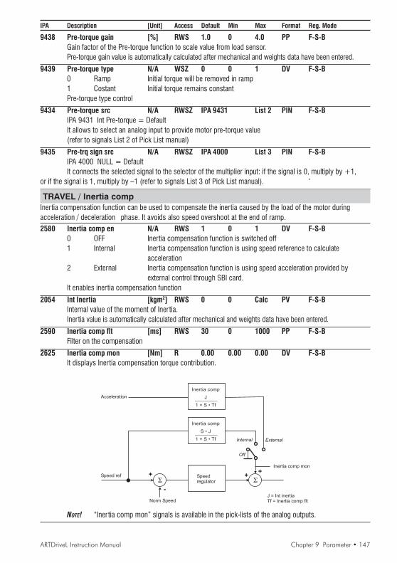
ARTDriveL Instruction Manual Chapter 9 Parameter • 147
IPA Description [Unit] Access Default Min Max Format Reg. Mode
9438 Pre-torque gain [%] RWS 1.0 0 4.0 PP F-S-BGain factor of the Pre-torque function to scale value from load sensor.Pre-torque gain value is automatically calculated after mechanical and weights data have been entered.
9439 Pre-torque type N/A WSZ 0 0 1 DV F-S-B0 Ramp Initial torque will be removed in ramp1 Costant Initial torque remains constantPre-torque type control
9434 Pre-torque src N/A RWSZ IPA 9431 List 2 PIN F-S-BIPA 9431 Int Pre-torque = DefaultIt allows to select an analog input to provide motor pre-torque value(refer to signals List 2 of Pick List manual)
9435 Pre-trq sign src N/A RWSZ IPA 4000 List 3 PIN F-S-BIPA 4000 NULL = DefaultIt connects the selected signal to the selector of the multiplier input: if the signal is 0, multiply by +1,
or if the signal is 1, multiply by –1 (refer to signals List 3 of Pick List manual). ‘
TRAVEL / Inertia compInertia compensation function can be used to compensate the inertia caused by the load of the motor duringacceleration / deceleration phase. It avoids also speed overshoot at the end of ramp.
2580 Inertia comp en N/A RWS 1 0 1 DV F-S-B0 OFF Inertia compensation function is switched off1 Internal Inertia compensation function is using speed reference to calculate
acceleration2 External Inertia compensation function is using speed acceleration provided by
external control through SBI card.It enables inertia compensation function
2054 Int Inertia [kgm2] RWS 0 0 Calc PV F-S-BInternal value of the moment of Iner tia.Inertia value is automatically calculated after mechanical and weights data have been entered.
2590 Inertia comp flt [ms] RWS 30 0 1000 PP F-S-BFilter on the compensation
2625 Inertia comp mon [Nm] R 0.00 0.00 0.00 DV F-S-BIt displays Inertia compensation torque contribution.
J = Int inertiaTf = Inertia comp flt
+
-
Speed ref Speedregulator
Inertia comp
S • J________
1 + S • Tf
+
Norm Speed
Inertia comp mon
+
Internal
Off
Inertia comp
J________
1 + S • Tf
External
Acceleration
NOTE! “Iner tia comp mon” signals is available in the pick-lists of the analog outputs.

148 • Chapter 9 Parameter ARTDriveL Instruction Manual
IPA Description [Unit] Access Default Min Max Format Reg. Mode
TRAVEL / DC brakingDC current injection can help to stop the motor and ensure that lift car arrives exactly at floor level.
1836 DCbrake cmd src N/A RWS IPA 7125 List 3 PIN V-F-S-BIPA 7125 Lift DC Brake mon = DefaultIt allows to select the origin of the signal to command DC braking function, normally if is controled by liftsequence. (refer to signals List 3 of Pick List manual)
1833 DCbrake delay [sec] RWS 0.1 0.01 30 PP V-F-S-BDelay between the injection command and the injection of the current itself
1834 DCbrake duration [sec] RWS 1 0.01 30 PP V-F-S-BDuration of the current injection
1835 DCbrake current [%] RWS 100 0 100 PP V-F-S-BBraking current as a percentage of Drive continuos current
1837 DCBrake state N/A R 0 0 1 DV V-F-S-B0 non-active1 activeState of DC Brake functon.
NOTE! Sequence available only when IPA 7105 set as Start fwd/rev.Lift DC brake mon signal that controls DC current braking is not available.
Speed ref
Speed 0 ref thr
DC brake current
0
DC brakedelay
Speed 0 ref dly + Brake close dly
Lift DC brake mon
t
1
A
B
DC brakeduration
DC brake state
Output current
DC brake cmd src
A = DC brake delay + DC brake duration > Spd 0 ref dly + Brake close dly
B = DC brake delay + DC brake duration < Spd 0 ref dly + Brake close dly
ARTDriveL Instruction Manual Chapter 9 Parameter • 149
IPA Description [Unit] Access Default Min Max Format Reg. Mode
TRAVEL / Ramp function8031 Ramp out enable N/A WSZ 1 0 1 DP V-F-S-B
0 Disabled1 EnabledRamp function enabling
8021 Ramp shape N/A RWS 1 0 1 DV V-F-S-B0 Linear1 S-ShapedRamp selection. Linear or S-shaped ramp
TRAVEL / Ramp setpointThe Function of this block is to generate the Set point for the ramp. Set reference by algebraically adding its inputs.All parameters in this menu have default values set for lift application.
TRAVEL / Ramp setpoint / Ramp ref src7035 Ramp ref 1 src N/A RWS IPA 7130 List 7 PIN V-F-S-B
IPA 7130 Lift out spd mon = DefaultIt select the origin of the signal of Ramp ref 1(refer to signals List 7 of Pick List manual)
7036 Ramp ref 2 src N/A RWS IPA 7031 List 8 PIN V-F-S-BIPA 7031 Int ramp ref 2 = DefaultIt select the origin of the signal of Ramp ref 2(refer to signals List 8 of Pick List manual)
7029 Ramp ref 3 src N/A RWS IPA 7038 List 45 PIN V-F-S-BIPA 7038 Int ramp ref 3 = DefaultIt select the origin of the signal of Ramp ref 3
7037 Ramp ref inv src N/A RWS IPA 4000 List 3 PIN V-F-S-BIPA 7121 DOWN Count mon = DefaultIt connects the selected signal to the selector of the multiplier input:if the signal is 0, multiply by +1,or if the signal is 1, multiply by –1. The multiplier allows to invert Ramp reference signal (refer to signalsList 3 of Pick List manual). By using DOWN cont mon / Up cont mon it is possible to invert liftmovement direction that corresponds to commands Start fwd src (IPA 7115), Start rev src (IPA 7116).
TRAVEL / Ramp setpoint / Ramp ref cfg7030 Int ramp ref 1 [rpm] RWS 0 Calc Calc PV V-F-S-B
Value of the Int ramp ref 1 variable
7031 Int ramp ref 2 [rpm] RWS 0 Calc Calc PV V-F-S-BValue of the Int ramp ref 2 variable
7038 Int ramp ref 3 [rpm] RWS 0 Calc Calc PV V-F-S-BValue of the Int ramp ref 3 variable
TRAVEL / Ramp setpoint / Ramp ref mon7032 Ramp ref 1 mon [rpm] R 0.00 0.00 0.00 PP V-F-S-B
Displaying of the Ramp ref 1 signal
7033 Ramp ref 2 mon [rpm] R 0.00 0.00 0.00 PP V-F-S-BDisplaying of the Ramp ref 2 signal
7039 Ramp ref 3 mon [rpm] R 0.00 0.00 0.00 PP V-F-S-BDisplaying of the Ramp ref 3 signal
7034 Ramp setpoint [rpm] R 0.00 0.00 0.00 PV V-F-S-BDisplaying of the Ramp setpoint output signal
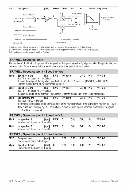
150 • Chapter 9 Parameter ARTDriveL Instruction Manual
IPA Description [Unit] Access Default Min Max Format Reg. Mode
+
+
+
+
-1
+1
F
21Ramp setpoint
Ramp ref inv src
DOWN Cont mon
Ramp ref = Rampout mon
Ramp shape
Ramp ref 3 mon
Ramp ref 2 mon
Ramp ref 1 mon
Ramp ref 3 src
Ramp ref 2 src
Ramp ref 1 src
Int ramp ref 3
Int ramp ref 2
Lift out spd mon
1. Switch is closed if Ramp out enable = Enabled & Start. Switch is opened if Ramp out enable = Enabled & Stop2. Switch is closed if Ramp out enable = Enabled & (!Fast stop). Switch is opened if Ramp out enable = Enabled & Fast stopBoth switches are closed if Ramp out enable = Disabled
TRAVEL / Speed setpointThe function of the block is to generate the set point for the speed regulator by algebraically adding its inputs, seeramp set point. All parameters in this menu have default values set for lift application.
TRAVEL / Speed setpoint / Speed ref src7050 Speed ref 1 src N/A RWS IPA 7040 List 9 PIN V-F-S-B
IPA 7040 Int speed ref 1 = DefaultIt select the origin of the signal of Speed ref 1 in V/f, SLS. LZ speed ref (IPA 9408) in FOC, BRS(refer to signals List 9 of Pick List manual)List 9)
7051 Speed ref 2 src N/A RWS IPA 7041 List 10 PIN V-F-S-BIPA 7041 Int speed ref 2 = DefaultIt select the origin of the signal of Speed ref 2. (Refer to signals List 10 of Pick List manual).
7053 Speedref inv src N/A RWS IPA 4000 List 3 PIN V-F-S-BIPA 4000 NULL = DefaultIt connects the selected signal to the selector of the multiplier input: if the signal is 0, multiply by +1, orif the signal is 1, multiply by –1. The multiplier allows to invert Speed reference signal (refer to signalsList 3 of Pick List manual)
TRAVEL / Speed setpoint / Speed ref cfg7040 Int speed ref 1 [rpm] RWS 0 Calc Calc PV V-F-S-B
Value of the Int speed ref 1 variable
7041 Int speed ref 2 [rpm] RWS 0 Calc Calc PV V-F-S-BValue of the Int speed ref 2 variable
TRAVEL / Speed setpoint / Speed ref mon8022 Ramp out mon [rpm] R 0.00 0.00 0.00 PV V-F-S-B
Displaying of Ramp output signal
7045 Speed ref 1 mon [rpm] R 0.00 0.00 0.00 PP V-F-S-BDisplaying of the Speed ref 1 signal

ARTDriveL Instruction Manual Chapter 9 Parameter • 151
IPA Description [Unit] Access Default Min Max Format Reg. Mode7046 Speed ref 2 mon [rpm] R 0.00 0.00 0.00 PP V-F-S-B
Displaying of the Speed ref 2 signal
1. Switch is closed if Ramp out enable = Disabled & Start
Both switches are closed if Ramp out enable = Enabled
Switch is opened if Ramp out enable = Disabled & Stop
2. Switch is closed if Ramp out enable = Disabled & (!Fast stop)
Switch is opened if Ramp out enable = Disabled & Fast stop
+
+
+
+
-1
+1
F
21Speed setpoint
Speed ref inv src=null
Ramp ref 2 mon
Ramp out enable
Int speed ref 1
Ramp out mon
0 rpm
F
Zero
Speed ref 1 mon
Speed ref 1 src
LZ speed ref
Int speed ref 2
0 rpm
Speed ref 2 src
Int speed ref 2
SAVE PARAMETERSAVyL drive allows two different commands to save the parameters modified in the regulation mode selected:• by STARTUP menu, “Save Config?” command• by all other menus, “SAVE PARAMETERS” commandAny changes made in STARTUP menu require “Save Config?” command, which saves all entire regulation mode selected.It is recommended every time the user made any changes into STARTUP menu.“SAVE PARAMETERS” command saves all the changes made out of STARTUP menu only.When on the keypad display appears blinking message “Use Save Config”, use “Save Config?” command
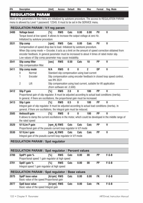
152 • Chapter 9 Parameter ARTDriveL Instruction Manual
IPA Description [Unit] Access Default Min Max Format Reg. Mode
REGULAREGULAREGULAREGULAREGULATION PTION PTION PTION PTION PARAMARAMARAMARAMARAMMost of the parameters in this menu are initialized by autotune procedure. The access to REGULATION PARAMmenu is allowed by Level 1 password: 12345. It must to be set in the SERVICE menu.
REGULATION PARAM / V/f reg param3400 Voltage boost [%] RWS Calc 0.00 0.00 PV V
Torque boost at low speed. It allows to increase the output voltage at zero Hz.Initialized by autotune procedure
3531 Slip comp [rpm] RWS Calc 0.00 Calc PV VCompensation of speed drop due to load. Initialized by autotune procedure.When Slip comp mode = Encoder, it acts as a limit on the amount of speed correction obtained fromencoder feedback. In general parameter must be increased to about 4 times of rated motor slip.Low values of Slip comp parameter may cause instability.
3541 Slip comp filter [sec] RWS 0.50 Calc 10 PP VSlip compensation filter.
3411 Slip comp mode N/A RWS 0 0 2 DP V0 Normal Standard slip compensation using load current1 Encoder Slip compensation using encoder feedback in closed loop speed control,
see IPA 35312 Lift Slip compensation using load current, suitable for lift application
(from software rel. 3.500).3412 Slip P gain [%] RWS 2.0 0 100 PP V
Proportional gain of slip regulator. It must be adjusted according to actual load conditions (inertia).In general, if there are oscillations, the proportional gain must be increased.
3413 Slip I gain [%] RWS 0.5 0 100 PP VIntegral gain of slip regulator. It must be adjusted according to actual load conditions (inertia). Ingeneral, if there are oscillations, the integral gain must be reduced.
3585 Antioscill gain [%] RWS 0 0 100 PP VIt allows to damp the current oscillations in the motor, which could be developed in the middle range ofthe rated speed
3520 V/f ILim P gain [rpm_A] RWS Calc Calc Calc PP VProportional gain of the pseudo current loop regulator in V/f mode
3530 V/f ILim I gain [rpm_A] RWS Calc Calc Calc PP VIntegral gain of the pseudo current loop regulator in V/f mode
REGULATION PARAM / Spd regulator
REGULATION PARAM / Spd regulator / Percent values3700 SpdP1 gain % [%] RWS Calc 0.00 00 PP F-S-B
Proportional speed 1 gain regulator at high speed
3701 SpdI1 gain % [%] RWS Calc 0.00 00 PP F-S-BIntegral speed 1 gain regulator at high speed
REGULATION PARAM / Spd regulator / Base values2075 SpdP base value [A/rpm] RWS Calc 0.00 0.00 FK F-S-B
Basic value of the speed Proportional gain
2077 SpdI base value [A/rpm] RWS Calc 0.00 Calc FK F-S-BBasic value of the speed Integral gain
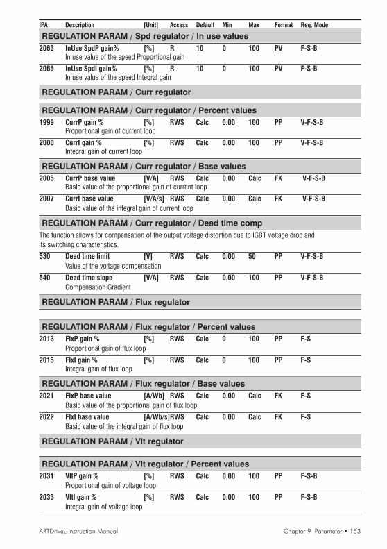
ARTDriveL Instruction Manual Chapter 9 Parameter • 153
IPA Description [Unit] Access Default Min Max Format Reg. Mode
REGULATION PARAM / Spd regulator / In use values2063 InUse SpdP gain% [%] R 10 0 100 PV F-S-B
In use value of the speed Proportional gain
2065 InUse SpdI gain% [%] R 10 0 100 PV F-S-BIn use value of the speed Integral gain
REGULATION PARAM / Curr regulator
REGULATION PARAM / Curr regulator / Percent values1999 CurrP gain % [%] RWS Calc 0.00 100 PP V-F-S-B
Proportional gain of current loop
2000 CurrI gain % [%] RWS Calc 0.00 100 PP V-F-S-BIntegral gain of current loop
REGULATION PARAM / Curr regulator / Base values2005 CurrP base value [V/A] RWS Calc 0.00 Calc FK V-F-S-B
Basic value of the proportional gain of current loop
2007 CurrI base value [V/A/s] RWS Calc 0.00 Calc FK V-F-S-BBasic value of the integral gain of current loop
REGULATION PARAM / Curr regulator / Dead time compThe function allows for compensation of the output voltage distortion due to IGBT voltage drop andits switching characteristics.
530 Dead time limit [V] RWS Calc 0.00 50 PP V-F-S-BValue of the voltage compensation
540 Dead time slope [V/A] RWS Calc 0.00 100 PP V-F-S-BCompensation Gradient
REGULATION PARAM / Flux regulator
REGULATION PARAM / Flux regulator / Percent values2013 FlxP gain % [%] RWS Calc 0 100 PP F-S
Proportional gain of flux loop
2015 FlxI gain % [%] RWS Calc 0 100 PP F-SIntegral gain of flux loop
REGULATION PARAM / Flux regulator / Base values2021 FlxP base value [A/Wb] RWS Calc 0.00 Calc FK F-S
Basic value of the proportional gain of flux loop
2022 FlxI base value [A/Wb/s]RWS Calc 0.00 Calc FK F-SBasic value of the integral gain of flux loop
REGULATION PARAM / Vlt regulator
REGULATION PARAM / Vlt regulator / Percent values2031 VltP gain % [%] RWS Calc 0.00 100 PP F-S-B
Proportional gain of voltage loop
2033 VltI gain % [%] RWS Calc 0.00 100 PP F-S-BIntegral gain of voltage loop

154 • Chapter 9 Parameter ARTDriveL Instruction Manual
IPA Description [Unit] Access Default Min Max Format Reg. Mode
REGULATION PARAM / Vlt regulator / Base values2039 VltP base value [A/V] RWS Calc 0.00 0.00 FK F-S-B
Basic value of the proportional gain of voltage loop
2041 VltI base value [A/V/s] RWS Calc 0.00 0.00 FK F-S-BBasic value of the integral gain of voltage loop
REGULATION PARAM / Torque config
+
+
Speed reg out
Inertia comp
Filter
Prop filter+
+
Torque ref 2 mon
Torque ref 2 src
Inuse Tcurr lim+
Tcurr ref
Torque refInuse Tcurr lim-Off
T lim +/-
T lim mot/gen
T lim sym var
T lim pos var
T lim neg var
Tcurr lim sel
REGULATION PARAM / Torque config / Torque setpoint / T setpoint src2441 Torque ref 2 src N/A RWS IPA 9433 List15 PIN F-S-B
IPA 9433 Pre-torque out = DefaultIt allows to select the origin of the signal for torque reference(refer to signals List 15 of Pick List manual)
REGULATION PARAM / Torque config / Torque setpoint / T setpoint cfg2440 Int torque ref 2 [Nm] RWS 0.00 Calc Calc PV F-S-B
It allows to set an alternative reference to connect to Torque ref 2 src
REGULATION PARAM / Torque config / Torque setpoint / T setpoint mon2442 Torque ref 2 mon [Nm] R 0.00 0.00 0.00 PP F-S-B
Torque ref 2 variable displaying
2450 Torque ref [Nm] R 0.00 0.00 0.00 PV F-S-BOverall Torque ref variable displaying
REGULATION PARAM / Torque config / Torque curr lim / Trq curr lim src1195 Trq curr lim src N/A RWS IPA 4000 List15 PIN V-F-S-B
IPA 4000 NULL = DefaultIt allows to select the origin of the signal for torque current limit(refer to signals List 15 of Pick List manual) (from software rel. 3.300).
REGULATION PARAM / Torque config / Torque curr lim / Trq curr lim cfg1190 Tcurr lim sel N/A RWS 0 0 4 DV V-F-S-B
0 Off None Limits depend on drive rating.1 T lim +/- Positive or negative limit Limits depend on IPA 1210, IPA12202 T lim mot/gen Motor or Generator limit Limits depend on IPA 1210, IPA12203 T lim sym var Limits are controlled by IPA 1195. (from software rel. 3.300).4 T lim pos var Limits are controlled by IPA 1195. (from software rel. 3.300).5 T lim neg var Limits are controlled by IPA 1195. (from software rel. 3.300).Selection of the torque Current limit type
1210 Tcurr lim + [A] RWS Calc 0.00 Calc PV V-F-S-BPositive current limit or Motor (Positive power) limit.

ARTDriveL Instruction Manual Chapter 9 Parameter • 155
IPA Description [Unit] Access Default Min Max Format Reg. Mode1220 Tcurr lim - [A] RWS Calc 0.00 Calc PV V-F-S-B
Negative current limit or Generator (Negative power) limit.
REGULATION PARAM / Torque config / Torque curr lim / Trq curr lim mon1250 Inuse Tcurr lim+ [A] R 0.00 0.00 0.00 PV V-F-S-B
Monitor of the positive current limit in use
1260 Inuse Tcurr lim- [A] R 0.00 0.00 0.00 PV V-F-S-BMonitor for the negative current limit in use
2445 Tcurr lim state N/A R 0 0 1 DV V-F-S-BCurrent limit state0 Not-reached1 Reached
REGULATION PARAM / Flux config
REGULATION PARAM / Flux config / Magnetiz configAutophase rot / Start ?
Autophasing command to phase brushless motors. After pressing Star t, give the Enable and Startcommand to drive. Motor must be free of any load, brake must be released.Motor will first align and then rotate slightly at very low speed.
Autophase still / Start ?Autophasing command to phase brushless motors. After pressing Star t, give the Enable and Startcommand to drive. Drive will perform phasing procedure without rotation. Brake can be locked
(from software rel. 3.500).
1810 Magn ramp time [sec] RWS D.Size 0.01 5 PP F-SSet of the ramp time of the magnetizing current
1815 Lock flux pos N/A RWSZ 0 0 1 DP F-S-B0 Off No locking of flux position1 At magnetization Flux position is locked during magnetization2 At Spd = 0 Flux positon is locked when stop command has been issued and
signal "Speed is zero delayed" becomes TRUE3 At Magn & Spd = 0 Flux positon is locked during magnetization or when stop
command has been issued and signal "Speed is zero delayed"becomes TRUE
4 At magn & Ref=0 Flux positon is locked during magnetization or when both signals"Speed reference is zero delayed" and "Speed is zero delayed"become TRUE
The function is useful for undesidered motor shaft rotation. It allows to lock the Flux position.
REGULATION PARAM / Flux config / Flux max limit / Flux max lim srcThis Function allows the user to control the maximum value of the Flux current.It is linked to the control of the voltage loop. In a condition where the Flux is = 100%, the voltage regulator prevailsby controlling the motor. It means that it is only possible to further limit the requirement of the voltage loop. In casethe Drive is active in the constant torque area, it is possible to set an overflux up to 115% of the rated flux. Suchcontrol is possible, obviously, only if the motor/drive combination is in a position to supply a sufficient magnetizingcurrent.1121 Flux level src N/A RWS IPA 1120 List 24 PIN F-S-B
IPA 1120 Int flx maxlim = DefaultIt allows to select the origin of the signal to control the function(refer to signals List 24 of Pick List manual)

156 • Chapter 9 Parameter ARTDriveL Instruction Manual
IPA Description [Unit] Access Default Min Max Format Reg. Mode
REGULATION PARAM / Flux config / Flux max limit / Flux max lim cfg1120 Int flx maxlim [%] RWS 0.00 0.00 0.00 PV F-S-B
It allows to set an alternative signal to connect to Flux level src
REGULATION PARAM / Flux config / Flux max limit / Flux max lim mon1150 Inuse flx maxlim [%] R 0.00 0.00 0.00 PV F-S-B
Monitor of flux limit value in use
REGULATION PARAM / Flux config / Output vlt refThe Function allows the regulation of the flux in the constant power area where a voltage margin must beavailable for the regulation. This value is usually equal to 2% of the maximum output voltage.A higher value allows a faster response of the voltage regulator but with a lower amount of available voltage on theoutput. A lower value allows a higher output voltage with a decrease of the dynamic performances
REGULATION PARAM / Flux config / Output vlt ref / Out vlt ref src1141 Outvlt lim src N/A RWS IPA 1140List 42 PIN F-S-B
IPA 1140 Int Outvlt lim = DefaultIt allows to select the origin of the signal to control the function(refer to signals List 42 of Pick List manual)
REGULATION PARAM / Flux config / Output vlt ref / Out vlt ref cfg1130 Dyn vlt margin [%] RWS 2 1 10 PV F-S-B
Voltage margin for the flux regulation
1140 Int Outvlt lim [V] RWS Calc Calc Calc PV F-S-BInternal output voltage limit. initialized from motor rated voltage.This parameter determines the start of flux weakening. Connected to Outvlt lim src
REGULATION PARAM / Flux config / Output vlt ref / Out vlt ref mon1170 Available Outvlt [V] R 0.00 0.00 0.00 PV F-S-B
Monitor for the maximum available output voltage.It is calculated directly starting from the DC link voltage
1180 Inuse Outvlt ref [V] R 0.00 0.00 0.00 PV F-S-BLimit in use on the output voltage
REGULATION PARAM / Sls SpdFbk gainsIn the Sensorless regulation mode the motor speed is estimated through an observer algorithm based on a speedgains profile. The procedure below allows the user to improve the gains profile of the observer circuit at low,medium and high Motoring/Regen speed.
REGULATION PARAM / Sls SpdFbk gains / Motoring gains1090 SLS mot HPgain [%] RWS 5 0 100 PP S
Motor Proportional High gain
1091 SLS mot HIgain [%] RWS 5 0 100 PP SMotor Integral High gain
1092 SLS mot MPgain [%] RWS 5 0 100 PP SMotor Proportional Medium gain
1093 SLS mot MIgain [%] RWS 5 0 100 PP SMotor Integral Medium gain
1094 SLS mot LPgain [%] RWS 1 0 100 PP SMotor Proportional Low gain

ARTDriveL Instruction Manual Chapter 9 Parameter • 157
IPA Description [Unit] Access Default Min Max Format Reg. Mode1095 SLS mot LIgain [%] RWS 0 0 100 PP S
Motor Integral Low gain
REGULATION PARAM / Sls SpdFbk gains / Regen gains1101 SLS regen HPgain [%] RWS 5 0 100 PP S
Regen Proportional High gain
1102 SLS regen HIgain [%] RWS 5 0 100 PP SRegen Integral High gain
1103 SLS regen MPgain [%] RWS 5 0 100 PP SRegen Proportional Medium gain
1104 SLS regen MIgain [%] RWS 5 0 100 PP SRegen Integral Medium gain
1105 SLS regen LPgain [%] RWS 1 0 100 PP SRegen Proportional Low gain
1106 SLS regen LIgain [%] RWS 0 0 100 PP SRegen Integral Low gain
REGULATION PARAM / Sls SpdFbk gains / Gain transitions1096 SLS H/M tran level [rpm] RWS Calc 0.00 Calc PP S
Transition level from High to Medium profile
1097 SLS M/L tran level [rpm] RWS Calc 0.00 Calc PP STransition level from Medium to Low profile
1098 SLS H/M tran bnd[rpm] RWS Calc 0.00 Calc PP STransition band from High to Medium profile
1099 SLS M/L tran bnd [rpm] RWS Calc 0.00 Calc PP STransition band from Medium to Low profile
1107 SLS 0 tran bnd [rpm] RWS Calc 0.00 Calc PP SSpeed 0 transition band (Motoring/Regen/Motoring)
1111 Observer filter [ms] RWS 100 Calc Calc PP STime constant of the first-order Filter on both gains profile
REGULATION PARAM / Sls SpdFbk gains / Gain monitor1085 Inuse S P gain [%] R 0.00 0.00 0.00 PV S
In use Proportional gains of speed observer.
1086 Inuse S I gain [%] R 0.00 0.00 0.00 PV SIn use Integral gains of speed observer.
1112 Observer ref mon [%] R 0.00 0.00 0.00 PP SObserver adapt gain reference monitor.
REGULATION PARAM / Test generatorThe tuning of the regulators can be done using an internal test signal generator in order to evaluate theregulator response. This operation requires the use of a digital oscilloscope. The “Test generator” generatessignal shaped as a rectangular wave with a programmable frequency and amplitude.Using the Test generator function it is possible to carry out the manual tunings of Current regulator, Flux regulatorVoltage regulator and Speed regulator.

158 • Chapter 9 Parameter ARTDriveL Instruction Manual
IPA Description [Unit] Access Default Min Max Format Reg. Mode
REGULATION PARAM / Test generator / Test gen mode2756 Test gen mode N/A RWS 0 0 6 DK V-F-S-B
0 Off1 Ramp ref 1 Ramp reference 12 Speed ref 1 Speed reference 13 Torque ref 2 Torque reference 24 Magn curr ref Magnetizing current reference5 Flux ref Flux reference6 Outvlt lim Voltage referenceThis parameter defines where the test signal is connected in the control scheme.
REGULATION PARAM / Test generator / Test gen cfg2745 Gen Hi ref [cnt] RWS 0 32767 -32767 PV V-F-S-B
Value in count of the higher amplitude signal value
2750 Gen Low ref [cnt] RWS 0 32767 -32767 PV V-F-S-BValue in count of the lower amplitude signal value
2755 Gen Period [sec] RWS 10 0 10000 PV V-F-S-BPeriod of the square wave
REGULATION PARAM / Test generator / Test gen mon2760 Gen output [cnt] R 0.00 0.00 0.00 PV V-F-S-B
Monitorig the test generator output signal.
t
Gen Hi ref
Gen output
Gen Low ref
Gen period
SAVE PARAMETERSAVyL drive allows two different commands to save the parameters modified in the regulation mode selected:• by STARTUP menu, “Save Config?” command• by all other menus, “SAVE PARAMETERS” commandAny changes made in STARTUP menu require “Save Config?” command, which saves all entire regulation mode selected.It is recommended every time the user made any changes into STARTUP menu.“SAVE PARAMETERS” command saves all the changes made out of STARTUP menu only.When on the keypad display appears blinking message “Use Save Config”, use “Save Config?” command

ARTDriveL Instruction Manual Chapter 9 Parameter • 159
IPA Description [Unit] Access Default Min Max Format Reg. Mode
I/O CONFIGI/O CONFIGI/O CONFIGI/O CONFIGI/O CONFIGThe access to I/O CONFIG menu is allowed by Level 1 password: 12345. It must all be set in the SERVICE menu.
I/O CONFIG / CommandsConfiguration of Enable, Start commands. All parameters in this menu have default values set for lift application.
I/O CONFIG / Commands / Commands src153 Term StrStp src N/A RWS IPA 4001 List 16 PIN V-F-S-B
IPA 4001 ONE = DefaultIt allows to select the signal to generate the Start (1) command and of the terminal strip Stop (0) command(refer to signals List 16 of Pick List manual)
9210 Term Start src N/A RWS IPA 4000 List 16 PIN V-F-S-BIPA 4000 NULL = DefaultIt allows to select the signal to generate the terminal strip Start command(refer to signals List 16 of Pick List manual)
9211 Term Stop src N/A RWS IPA 4000 List 16 PIN V-F-S-BIPA 4000 NULL = DefaultIt allows to select the signal to generate the terminal strip Stop command(refer to signals List 16 of Pick List manual)
156 Dig Enable src N/A RWS IPA 7128 List 17 PIN V-F-S-BIPA 7128 Lift Enable mon= DefaultIt allows to select the signal to generate a digital Enable command(refer to signals List 17 of Pick List manual)
157 Dig StrStp src N/A RWS IPA 7129 List 17 PIN V-F-S-BIPA 7129 Lift Start mon = DefaultIt allows to select the signal to generate the a digital Start (1) command and a digital Stop (0) command(refer to signals List 17 of Pick List manual)
154 FastStop src N/A RWS IPA 4000 List 18 PIN V-F-S-BIPA 4000 NULL = DefaultIt allows to select the signal to generate the FastStop command(refer to signals List 18 of Pick List manual)
I/O CONFIG / Commands / Commands cfg“Commands select” parameter determines the logic for the Start/Stop Edge sensitive signal orLevel sensitive signal or I O keys keypad commands control
4002 Commands select N/A RWS 2 0 4 DV V-F-S-B0 Terminals Level The drive is controlled via terminal strip using a Level sensitive signals1 Terminals Edge The drive is controlled via terminal strip using a Edge sensitive signals2 Digital Level The drive is controlled from a communication or application card using a
Level sensitive signals3 Digital Edge The drive is controlled from a communication or application card using a
Edge sensitive signals4 I O keys The drive is controlled from the keyboard using the I O keys;
terminal 12 to and terminal 13 to 24Vdc are requiredSetting of this parameter is not allowed while terminal enable is active.
4004 En/Disable mode N/A RWS 0 0 3 DP V-F-S-B0 Off1 Stop/FS & Spd=02 Stop & Spd=03 FS & Spd=0It controls the action time of the stop condition.Setting of this parameter is not allowed while terminal enable is active.
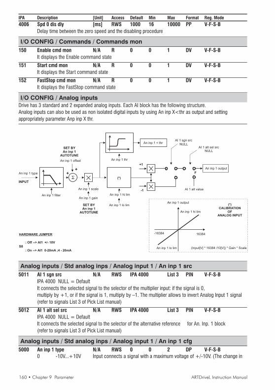
160 • Chapter 9 Parameter ARTDriveL Instruction Manual
IPA Description [Unit] Access Default Min Max Format Reg. Mode4006 Spd 0 dis dly [ms] RWS 1000 16 10000 PP V-F-S-B
Delay time between the zero speed and the disabling procedure
I/O CONFIG / Commands / Commands mon150 Enable cmd mon N/A R 0 0 1 DV V-F-S-B
It displays the Enable command state
151 Start cmd mon N/A R 0 0 1 DV V-F-S-BIt displays the Start command state
152 FastStop cmd mon N/A R 0 0 1 DV V-F-S-BIt displays the FastStop command state
I/O CONFIG / Analog inputsDrive has 3 standard and 2 expanded analog inputs. Each AI block has the following structure.Analog inputs can also be used as non isolated digital inputs by using An inp X<thr as output and settingappropriately parameter Anp inp X thr.
+1
-1
(*)
HARDWARE JUMPER
: Off --> AI1 +/- 10V
S8
: On --> AI1 0-20mA ;4 - 20mA
SET BYAn inp 1
AUTOTUNE
SET BYAn inp 1
AUTOTUNE
+
+
INPUT
F
An inp 1 output
16384-16384
An inp 1 hi lim
An inp 1 lo lim (Input[V] * 16384 /10[V]) * Gain * Scale
(*)CALIBRATION
OFANALOG INPUT
An inp 1 output
An inp 1 type
An inp 1 filter
An inp 1 offset An inp 1 thr
An inp 1 scale
An inp 1 gain
An inp 1 < thr
An inp 1 hi lim
An inp 1 lo lim
NULL
AI 1 sgn src
AI 1 alt sel srcNULL
AI 1 alt value
Analog inputs / Std analog inps / Analog input 1 / An inp 1 src5011 AI 1 sgn src N/A RWS IPA 4000 List 3 PIN V-F-S-B
IPA 4000 NULL = DefaultIt connects the selected signal to the selector of the multiplier input: if the signal is 0,multiply by +1, or if the signal is 1, multiply by –1. The multiplier allows to invert Analog Input 1 signal(refer to signals List 3 of Pick List manual)
5012 AI 1 alt sel src N/A RWS IPA 4000 List 3 PIN V-F-S-BIPA 4000 NULL = DefaultIt connects the selected signal to the selector of the alternative reference for An. Inp. 1 block(refer to signals List 3 of Pick List manual)
Analog inputs / Std analog inps / Analog input 1 / An inp 1 cfg5000 An inp 1 type N/A RWS 0 0 2 DP V-F-S-B
0 -10V...+10V Input connects a signal with a maximum voltage of +/-10V. (The change in

ARTDriveL Instruction Manual Chapter 9 Parameter • 161
IPA Description [Unit] Access Default Min Max Format Reg. Mode
the motor rotation direction is obtained according to the signal polarity).Input voltage > 10V or >-10V cause saturation of the count value.
1 0..20mA,0..10V On the input it’s possible to connect a max voltage of +10V or a 0…20mAcurrent signal. The signal must always have a positive sign, through which,if used as a reference, it is possible to change the motor rotation direction via“AI 1 sgn src”
2 4..20mA On the input it is possible to connect a 4… 20mA current signal.The signal must always have a positive sign through which, if used as areference, it is possible to change the motor rotation direction via “AI 1 sgn src”.Through the An inp X <thr output it is possible to state if the current signal islower than the one of the set threshold. If the current is <= 4mA , theoutput supplies a signal (error signal). This, for example, can be combined
with a digital outputNOTE! “An inp 1 type” selection requires a correct jumpers configuration of RV33 regulation card:
-10V...+10V & 0..10V S8=OFF – S9=OFF – S10=OFF0..20mA & 4..20mA S8=ON – S9= ON – S10= ON
5002 AI 1 alt value [cnt] RWS 0 32767 -32767 PV V-F-S-BAlternative reference value in count for Analog input 1
5003 An inp 1 thr [cnt] RWS 3277 -16384 16383 PP V-F-S-BAnalog Input 1 threshold value in count
5004 An inp 1 scale N/A RWS 1 -16 16 PP V-F-S-BAnalog Input 1 scale factor
5006 An inp 1 filter [sec] RWS 0.0064 0.00 4.096 PP V-F-S-BTime constant of the Analog Input 1 filter
5007 An inp 1 low lim [cnt] RWS -16384 -32768 32767 PP V-F-S-BLower limit of the Analog Input 1 block output in count (see figure below)
5008 An inp 1 hi lim [cnt] RWS 16383 -32768 32767 PP V-F-S-BUpper limit of the Analog Input 1 block output in count (see figure below)
AI 1 offs tune / Start?Autotune command for the Analog Input 1 offset. Input automatic fine-tuning.To run the autotune, put the input signal to its minimum value and execute “Star t ?” command
AI 1 gain tune / Start?Autotune command for the Analog Input 1 gain. Conditions containing an offset can be compensated.To run the autotune, put the input signal to its maximum value and execute “Start ?” command
Analog inputs / Std analog inps / Analog input 1 / An inp 1 mon5009 An inp 1 output [cnt] R 0.00 -32768 32767 PV V-F-S-B
Analog Input 1 output count displaying
5010 An inp 1 < thr N/A R 0 0 1 DV V-F-S-BDisplay of threshold compensator state of Analog Input 1 (1 = the condition is true)
5001 An inp 1 offset [cnt] RWS 0 -16384 16383 PP V-F-S-BAnalog Input 1 offset count value displaying
5005 An inp 1 gain N/A RWS 1 -16 16 PP V-F-S-BAnalog Input 1 gain count value displaying
Analog inputs / Std analog inps / Analog input 2 / An inp 2 src5031 AI 2 sgn src N/A RWS IPA 4000 List 3 PIN V-F-S-B
IPA 4000 NULL = DefaultIt connects the selected signal to the selector of the multiplier input: if the signal is 0,

162 • Chapter 9 Parameter ARTDriveL Instruction Manual
IPA Description [Unit] Access Default Min Max Format Reg. Modemultiply by +1, or if the signal is 1, multiply by –1. The multiplier allows to invert Analog Input 2 signal(refer to signals List 3 of Pick List manual)
5032 AI 2 alt sel src N/A RWS IPA 4000List 3 PIN V-F-S-BIPA 4000 NULL = DefaultIt connects the selected signal to the selector of the alternative reference for An. Inp. 2 block(refer to signals List 3 of Pick List manual)
Analog inputs / Std analog inps / Analog input 2 / An inp 2 cfg5020 An inp 2 type N/A RWS 0 0 2 DP V-F-S-B
0 -10V ... +10V1 0..20mA,0..10V3 4..20mAFor “An inp 2 type” description refer to “An inp 1 type” description above
5022 AI 2 alt value [cnt] RWS 0 32767 -32767 PV V-F-S-BAlternative reference value in count for Analog input 2
5023 An inp 2 thr [cnt] RWS 3277 -16384 16383 PP V-F-S-BAnalog Input 2 threshold value in count
5024 An inp 2 scale N/A RWS 1 -16 16 PP V-F-S-BAnalog Input 2 scale factor
5026 An inp 2 filter [sec] RWS 0.0064 0.00 4.096 PP V-F-S-BTime constant of the Analog Input 2 filter
5027 An inp 2 lo lim [cnt] RWS -16384 -32768 32767 PP V-F-S-BLower limit of the Analog Input 2 block output in count (see figure of Analog Input 1 above)
5028 An inp 2 hi lim [cnt] RWS 16383 -32768 32767 PP V-F-S-BUpper limit of the Analog Input 2 block output in count (see figure of Analog Input 1 above)
AI 2 offs tune / Start?Refer to “AI 1 offs tune” description above
AI 2 gain tune / Start?Refer to “AI 1 gain tune” description above
Analog inputs / Std analog inps / Analog input 2 / An inp 2 mon5029 An inp 2 output [cnt] R 0.00 -32768 32767 PV V-F-S-B
Analog Input 2 output count displaying
5030 An inp 2 < thr N/A R 0 0 1 DV V-F-S-BDisplay of threshold compensator state of Analog Input 2 (1 = the condition is true)
5021 An inp 2 offset [cnt] RWS 0 -16384 16383 PP V-F-S-BAnalog Input 2 offset count value displaying
5025 An inp 2 gain N/A RWS 1 -16 16 PP V-F-S-BAnalog Input 2 gain count value displaying
Analog inputs / Std analog inps / Analog input 3 / An inp 3 src5051 AI 3 sgn src N/A RWS IPA 4000 List 3 PIN V-F-S-B
IPA 4000 NULL = DefaultIt connects the selected signal to the selector of the multiplier input: if the signal is 0,multiply by +1, or if the signal is 1, multiply by –1. The multiplier allows to invert Analog Input 3 signal(refer to signals List 3 of Pick List manual)
5052 AI 3 alt sel src N/A RWS IPA 4000 List 3 PIN V-F-S-BIPA 4000 NULL = Default
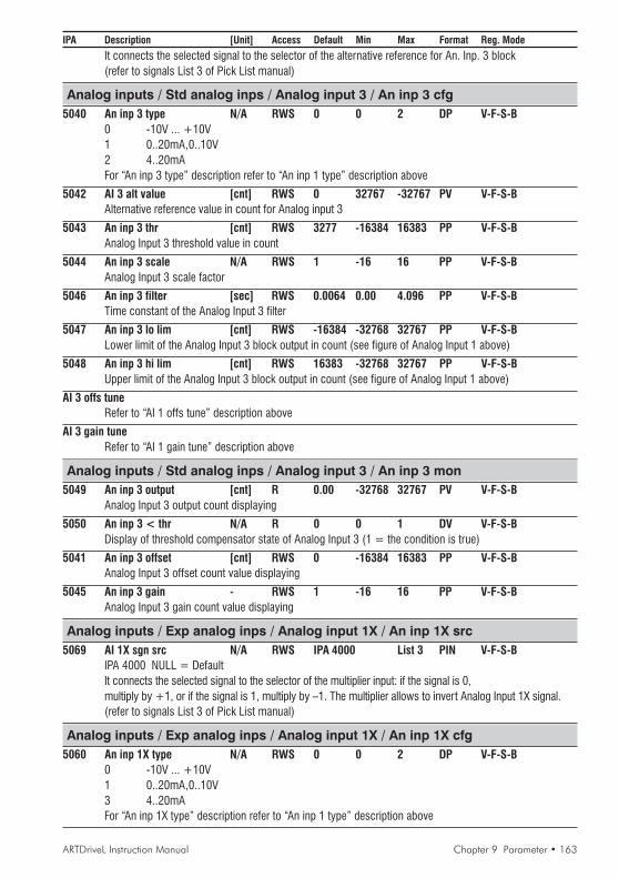
ARTDriveL Instruction Manual Chapter 9 Parameter • 163
IPA Description [Unit] Access Default Min Max Format Reg. Mode
It connects the selected signal to the selector of the alternative reference for An. Inp. 3 block(refer to signals List 3 of Pick List manual)
Analog inputs / Std analog inps / Analog input 3 / An inp 3 cfg5040 An inp 3 type N/A RWS 0 0 2 DP V-F-S-B
0 -10V ... +10V1 0..20mA,0..10V2 4..20mAFor “An inp 3 type” description refer to “An inp 1 type” description above
5042 AI 3 alt value [cnt] RWS 0 32767 -32767 PV V-F-S-BAlternative reference value in count for Analog input 3
5043 An inp 3 thr [cnt] RWS 3277 -16384 16383 PP V-F-S-BAnalog Input 3 threshold value in count
5044 An inp 3 scale N/A RWS 1 -16 16 PP V-F-S-BAnalog Input 3 scale factor
5046 An inp 3 filter [sec] RWS 0.0064 0.00 4.096 PP V-F-S-BTime constant of the Analog Input 3 filter
5047 An inp 3 lo lim [cnt] RWS -16384 -32768 32767 PP V-F-S-BLower limit of the Analog Input 3 block output in count (see figure of Analog Input 1 above)
5048 An inp 3 hi lim [cnt] RWS 16383 -32768 32767 PP V-F-S-BUpper limit of the Analog Input 3 block output in count (see figure of Analog Input 1 above)
AI 3 offs tuneRefer to “AI 1 offs tune” description above
AI 3 gain tuneRefer to “AI 1 gain tune” description above
Analog inputs / Std analog inps / Analog input 3 / An inp 3 mon5049 An inp 3 output [cnt] R 0.00 -32768 32767 PV V-F-S-B
Analog Input 3 output count displaying
5050 An inp 3 < thr N/A R 0 0 1 DV V-F-S-BDisplay of threshold compensator state of Analog Input 3 (1 = the condition is true)
5041 An inp 3 offset [cnt] RWS 0 -16384 16383 PP V-F-S-BAnalog Input 3 offset count value displaying
5045 An inp 3 gain - RWS 1 -16 16 PP V-F-S-BAnalog Input 3 gain count value displaying
Analog inputs / Exp analog inps / Analog input 1X / An inp 1X src5069 AI 1X sgn src N/A RWS IPA 4000 List 3 PIN V-F-S-B
IPA 4000 NULL = DefaultIt connects the selected signal to the selector of the multiplier input: if the signal is 0,multiply by +1, or if the signal is 1, multiply by –1. The multiplier allows to invert Analog Input 1X signal.(refer to signals List 3 of Pick List manual)
Analog inputs / Exp analog inps / Analog input 1X / An inp 1X cfg5060 An inp 1X type N/A RWS 0 0 2 DP V-F-S-B
0 -10V ... +10V1 0..20mA,0..10V3 4..20mAFor “An inp 1X type” description refer to “An inp 1 type” description above
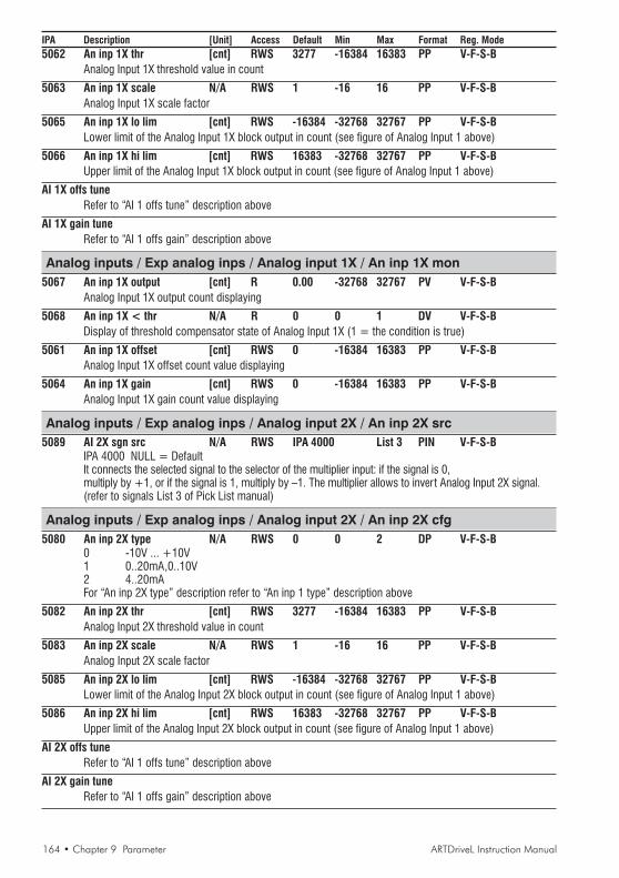
164 • Chapter 9 Parameter ARTDriveL Instruction Manual
IPA Description [Unit] Access Default Min Max Format Reg. Mode5062 An inp 1X thr [cnt] RWS 3277 -16384 16383 PP V-F-S-B
Analog Input 1X threshold value in count
5063 An inp 1X scale N/A RWS 1 -16 16 PP V-F-S-BAnalog Input 1X scale factor
5065 An inp 1X lo lim [cnt] RWS -16384 -32768 32767 PP V-F-S-BLower limit of the Analog Input 1X block output in count (see figure of Analog Input 1 above)
5066 An inp 1X hi lim [cnt] RWS 16383 -32768 32767 PP V-F-S-BUpper limit of the Analog Input 1X block output in count (see figure of Analog Input 1 above)
AI 1X offs tuneRefer to “AI 1 offs tune” description above
AI 1X gain tuneRefer to “AI 1 offs gain” description above
Analog inputs / Exp analog inps / Analog input 1X / An inp 1X mon5067 An inp 1X output [cnt] R 0.00 -32768 32767 PV V-F-S-B
Analog Input 1X output count displaying
5068 An inp 1X < thr N/A R 0 0 1 DV V-F-S-BDisplay of threshold compensator state of Analog Input 1X (1 = the condition is true)
5061 An inp 1X offset [cnt] RWS 0 -16384 16383 PP V-F-S-BAnalog Input 1X offset count value displaying
5064 An inp 1X gain [cnt] RWS 0 -16384 16383 PP V-F-S-BAnalog Input 1X gain count value displaying
Analog inputs / Exp analog inps / Analog input 2X / An inp 2X src5089 AI 2X sgn src N/A RWS IPA 4000 List 3 PIN V-F-S-B
IPA 4000 NULL = DefaultIt connects the selected signal to the selector of the multiplier input: if the signal is 0,multiply by +1, or if the signal is 1, multiply by –1. The multiplier allows to invert Analog Input 2X signal.(refer to signals List 3 of Pick List manual)
Analog inputs / Exp analog inps / Analog input 2X / An inp 2X cfg5080 An inp 2X type N/A RWS 0 0 2 DP V-F-S-B
0 -10V ... +10V1 0..20mA,0..10V2 4..20mAFor “An inp 2X type” description refer to “An inp 1 type” description above
5082 An inp 2X thr [cnt] RWS 3277 -16384 16383 PP V-F-S-BAnalog Input 2X threshold value in count
5083 An inp 2X scale N/A RWS 1 -16 16 PP V-F-S-BAnalog Input 2X scale factor
5085 An inp 2X lo lim [cnt] RWS -16384 -32768 32767 PP V-F-S-BLower limit of the Analog Input 2X block output in count (see figure of Analog Input 1 above)
5086 An inp 2X hi lim [cnt] RWS 16383 -32768 32767 PP V-F-S-BUpper limit of the Analog Input 2X block output in count (see figure of Analog Input 1 above)
AI 2X offs tuneRefer to “AI 1 offs tune” description above
AI 2X gain tuneRefer to “AI 1 offs gain” description above

ARTDriveL Instruction Manual Chapter 9 Parameter • 165
IPA Description [Unit] Access Default Min Max Format Reg. Mode
Analog inputs / Exp analog inps / Analog input 2X / An inp 2X mon5087 An inp 2X output [cnt] R 0.00 -32768 32767 PV V-F-S-B
Analog Input 2X output count displaying
5088 An inp 2X < thr N/A R 0.00 0.00 0.00 DV V-F-S-BDisplay of threshold compensator state of Analog Input 2X (1 = the condition is true)
5081 An inp 2X offset [cnt] RWS 0 -16384 16383 PP V-F-S-BAnalog Input 2X offset count value displaying
5084 An inp 2X gain [cnt] RWS 0 -16384 16383 PP V-F-S-BAnalog Input 2X gain count value displaying
Analog inputs / Exp analog inps / Exp ana inp en3900 Exp ana inp en N/A RWS 0 0 1 DV V-F-S-B
0 Disabled2 EnabledIt enables Expanded Analog Inputs
Analog inputs / DestinationsThis read-only menu allows the user to see where the Analog inputs are connected. If more then one sourceis connected to an Analog Input, only one is shown. If no sources are connected the message “Not used” is displayed.
4500 An inp 1 dstIt displays the Analog Input 1 destination
4501 An inp 2 dstIt displays the Analog Input 2 destination
4502 An inp 3 dstIt displays the Analog Input 3 destination
4503 An inp 1X dstIt displays the Analog Input 1X destination
4504 An inp 2X dstIt displays the Analog Input 2X destination
I/O CONFIG / Analog outputs
CALIBRATION TO +/-10 V OUTPUTAn out 1 mon (in counts) * An out 1 scale = An out 1 hi lim (in counts) = 10 V
An out 1 mon (in counts) * An out 1 scale = An out 1 lo lim (in counts) = -10 V
Analog Output 1
Software version 3.200
An out 1 scale1
An out 1 hi lim16383 cnt
An out 1 lo lim-16384 cnt
An out 1 srcNULL
An out 1 mon

166 • Chapter 9 Parameter ARTDriveL Instruction Manual
IPA Description [Unit] Access Default Min Max Format Reg. Mode
Software version 3.300
An out 1 sgn src
An out 1 src
NULL
An out 1 mon
1
-1
NULL
ONE
Drive has 2 standard (voltage outputs) and 4 expanded analog outputs (1x and 2x = volatge outputs, 3x and4x=current outputs). Each Analog output block has the following structure.
Analog outputs / Std analog outs / Analog output 1 / An out 1 src3570 An out 1 src N/A RWS IPA 4000 List 2 V-F-S-B
IPA 4000 NULL = DefaultIt allows to connect the selected signal to the Analog output 1(refer to signals List 2 of Pick List manual)
3575 An out 1 sgn src N/A RWS IPA 4000 List 2 V-F-S-BIt allows to select the sign of the signal connected on analog output. (from software rel. 3.300)
Analog outputs / Std analog outs / Analog output 1 / An out 1 cfg6012 An out 1 scale N/A RWS 1 -10 10 PP V-F-S-B
Scale or multiplicative factor of Analog output 1
6010 An out 1 hi lim [cnt] RWS 16383 0 32767 PP V-F-S-BAnalog output 1 count value aimed at obtaining +10V. Value must be higher than zero
6011 An out 1 lo lim [cnt] RWS -16384 -32768 0 PP V-F-S-BAnalog output 1 count value aimed at obtaining -10V. Value must be higher than zero
Analog outputs / Std analog outs / Analog output 1 / An out 1 mon6013 An out 1 mon [cnt] R 0 -32768 32767 PP V-F-S-B
Analog output 1 count value displaying
Analog outputs / Std analog outs / Analog output 2 / An out 2 src3580 An out 2 src N/A RWS IPA 4000 List 2 V-F-S-B
IPA 4000 NULL = DefaultIt allows to connect the selected signal to the Analog output 2(refer to signals List 2 of Pick List manual)
3576 An out 2 sgn src N/A RWS IPA 4000 List 2 V-F-S-BIt allows to select the sign of the signal connected on analog output. (from software rel. 3.300)
Analog outputs / Std analog outs / Analog output 2 / An out 2 cfg6017 An out 2 scale N/A RWS 1 -10 10 PP V-F-S-B
Scale or multiplicative factor of Analog output 2
6015 An out 2 hi lim [cnt] RWS 16383 0 32767 PP V-F-S-BAnalog output 2 count value aimed at obtaining +10V. Value must be higher than zero
6016 An out 2 lo lim [cnt] RWS -16384 -32768 0 PP V-F-S-BAnalog output 2 count value aimed at obtaining -10V. Value must be higher than zero
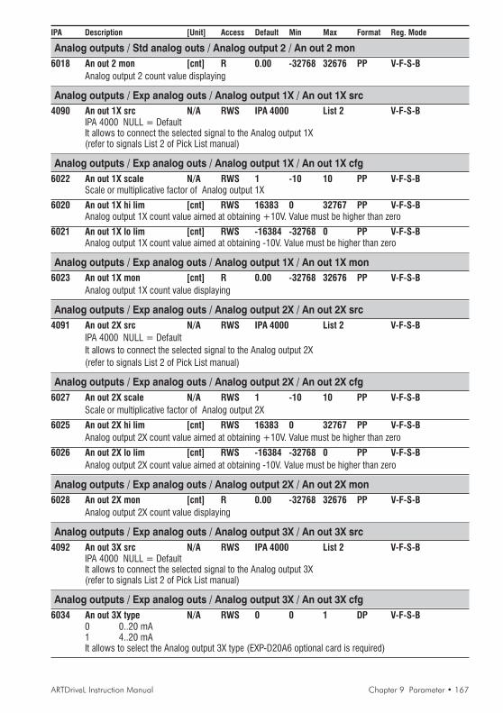
ARTDriveL Instruction Manual Chapter 9 Parameter • 167
IPA Description [Unit] Access Default Min Max Format Reg. Mode
Analog outputs / Std analog outs / Analog output 2 / An out 2 mon6018 An out 2 mon [cnt] R 0.00 -32768 32676 PP V-F-S-B
Analog output 2 count value displaying
Analog outputs / Exp analog outs / Analog output 1X / An out 1X src4090 An out 1X src N/A RWS IPA 4000 List 2 V-F-S-B
IPA 4000 NULL = DefaultIt allows to connect the selected signal to the Analog output 1X(refer to signals List 2 of Pick List manual)
Analog outputs / Exp analog outs / Analog output 1X / An out 1X cfg6022 An out 1X scale N/A RWS 1 -10 10 PP V-F-S-B
Scale or multiplicative factor of Analog output 1X
6020 An out 1X hi lim [cnt] RWS 16383 0 32767 PP V-F-S-BAnalog output 1X count value aimed at obtaining +10V. Value must be higher than zero
6021 An out 1X lo lim [cnt] RWS -16384 -32768 0 PP V-F-S-BAnalog output 1X count value aimed at obtaining -10V. Value must be higher than zero
Analog outputs / Exp analog outs / Analog output 1X / An out 1X mon6023 An out 1X mon [cnt] R 0.00 -32768 32676 PP V-F-S-B
Analog output 1X count value displaying
Analog outputs / Exp analog outs / Analog output 2X / An out 2X src4091 An out 2X src N/A RWS IPA 4000 List 2 V-F-S-B
IPA 4000 NULL = DefaultIt allows to connect the selected signal to the Analog output 2X(refer to signals List 2 of Pick List manual)
Analog outputs / Exp analog outs / Analog output 2X / An out 2X cfg6027 An out 2X scale N/A RWS 1 -10 10 PP V-F-S-B
Scale or multiplicative factor of Analog output 2X
6025 An out 2X hi lim [cnt] RWS 16383 0 32767 PP V-F-S-BAnalog output 2X count value aimed at obtaining +10V. Value must be higher than zero
6026 An out 2X lo lim [cnt] RWS -16384 -32768 0 PP V-F-S-BAnalog output 2X count value aimed at obtaining -10V. Value must be higher than zero
Analog outputs / Exp analog outs / Analog output 2X / An out 2X mon6028 An out 2X mon [cnt] R 0.00 -32768 32676 PP V-F-S-B
Analog output 2X count value displaying
Analog outputs / Exp analog outs / Analog output 3X / An out 3X src4092 An out 3X src N/A RWS IPA 4000 List 2 V-F-S-B
IPA 4000 NULL = DefaultIt allows to connect the selected signal to the Analog output 3X(refer to signals List 2 of Pick List manual)
Analog outputs / Exp analog outs / Analog output 3X / An out 3X cfg6034 An out 3X type N/A RWS 0 0 1 DP V-F-S-B
0 0..20 mA1 4..20 mAIt allows to select the Analog output 3X type (EXP-D20A6 optional card is required)

168 • Chapter 9 Parameter ARTDriveL Instruction Manual
IPA Description [Unit] Access Default Min Max Format Reg. Mode
6032 An out 3X scale N/A RWS 1 -10 10 PP V-F-S-BScale or multiplicative factor of Analog output 3X
6030 An out 3X hi lim [cnt] RWS 16383 0 32767 PP V-F-S-BAnalog output 3X count value aimed at obtaining +10V. Value must be higher than zero
6031 An out 3X lo lim [cnt] RWS -16384 -32768 0 PP V-F-S-BAnalog output 3X count value aimed at obtaining -10V. Value must be higher than zero
Analog outputs / Exp analog outs / Analog output 3X / An out 3X mon6033 An out 3X mon [cnt] R 0.00 -32768 32676 PP V-F-S-B
Analog output 3X count value displaying
Analog outputs / Exp analog outs / Analog output 4X / An out 4X src4093 An out 4X src N/A RWS IPA 4000 List 2 V-F-S-B
IPA 4000 NULL = DefaultIt allows to connect the selected signal to the Analog output 4X(refer to signals List 2 of Pick List manual)
Analog outputs / Exp analog outs / Analog output 4X / An out 4X cfg6039 An out 4x type N/A RWS 0 0 1 DP V-F-S-B
0 0..20 mA1 4..20 mAIt allows to select the Analog output 4X type (EXP-D20A6 optional card is required)
6037 An out 4X scale N/A RWS 1 -10 10 PP V-F-S-BScale or multiplicative factor of Analog output 4X
6035 An out 4X hi lim [cnt] RWS 16383 0 32767 PP V-F-S-BAnalog output 4X count value aimed at obtaining +10V. Value must be higher than zero
6036 An out 4X lo lim [cnt] RWS -16384 -32768 0 PP V-F-S-BAnalog output 4X count value aimed at obtaining -10V. Value must be higher than zero
Analog outputs / Exp analog outs / Analog output 4X / An out 4X mon6038 An out 4X mon [cnt] R 0.00 -32768 32676 PP V-F-S-B
Analog output 4X count value displaying
Analog outputs / Exp analog outs / Exp ana out en3901 Exp ana out en N/A RWS 0 0 1 DV V-F-S-B
0 Disabled1 EnabledIt enables the expanded analog outputs

ARTDriveL Instruction Manual Chapter 9 Parameter • 169
IPA Description [Unit] Access Default Min Max Format Reg. Mode
I/O CONFIG / Digital inputsDigital Input Block function allows to invert the signal on the terminal strip.For example, if the potential available on the terminal strip is +24V, and the inversion is disabled (not inverted) theinput state is 1 (ONE), standard configuration; if the inversion is enabled (inversion) the input state is 0 (NULL). TheDrive ENABLE is set on the “Digital input 0”; such condition can not be changed as it is performed via the hardware.Its function, anyway, can be combined with a command signal in the sources of the other Blocks. “DI 0 Enablemon” signal (Digital input 0 signal) is available in the “List 3”.
F
Hw Drive Enable
En/ DI 0
Di 1
DI 2 inversion
Not invertedDI 2 monitor
DI 0 Enable mon
DI 3 inversion
Not inverted
DI 4 inversion
Not inverted
DI 5 inversion
Not inverted
DI 6 inversion
Not inverted
DI 7 inversion
Not inverted
DI 3 monitor
DI 4 monitor
DI 5 monitor
DI 6 monitor
DI 7 monitor
DI 1 inversion
DI 1 monitor
I/O CONFIG / Digital inputs / Std digital inps / Std dig inp cfg4011 DI 1 inversion N/A RWS 0 0 1 DP V-F-S-B
0 Not inverted1 Inverted
4012 DI 2 inversion N/A RWS 0 0 1 DP V-F-S-B0 Not inverted1 Inverted
4013 DI 3 inversion N/A RWS 0 0 1 DP V-F-S-B0 Not inverted1 Inverted
4014 DI 4 inversion N/A RWS 0 0 1 DP V-F-S-B0 Not inverted1 Inverted
4015 DI 5 inversion N/A RWS 0 0 1 DP V-F-S-B0 Not inverted1 Inverted
4016 DI 6 inversion N/A RWS 0 0 1 DP V-F-S-B0 Not inverted1 Inverted

170 • Chapter 9 Parameter ARTDriveL Instruction Manual
IPA Description [Unit] Access Default Min Max Format Reg. Mode4017 DI 7 inversion N/A RWS 0 0 1 DP V-F-S-B
0 Not inverted1 Inverted
I/O CONFIG / Digital inputs / Std digital inps / Std dig inp mon4020 DI 0 Enable mon N/A R 0 0 1 DV V-F-S-B
Enable terminal displaying
4021 DI 1 monitor N/A R 0 0 1 DV V-F-S-BDigital Input 1 terminal displaying
4022 DI 2 monitor N/A R 0 0 1 DV V-F-S-BDigital Input 2 terminal displaying
4023 DI 3 monitor N/A R 0 0 1 DV V-F-S-BDigital Input 3 terminal displaying
4024 DI 4 monitor N/A R 0 0 1 DV V-F-S-BDigital Input 4 terminal displaying
4025 DI 5 monitor N/A R 0 0 1 DV V-F-S-BDigital Input 5 terminal displaying
4026 DI 6 monitor N/A R 0 0 1 DV V-F-S-BDigital Input 6 terminal displaying
Digital Input 6 terminal displaying4027 DI 7 monitor N/A R 0 0 1 DV V-F-S-B
Digital Input 7 terminal displaying
4028 DI 7654321E N/A R 0 0 - DP V-F-S-BStandard digital inputs displaying. Under each number the logical state of each single input is displayed.
I/O CONFIG / Digital inputs / Exp digital inps / Exp dig inp cfg4030 DI 0X inversion N/A RWS 0 0 1 DP V-F-S-B
0 Not inverted1 Inverted
4031 DI 1X inversion N/A RWS 0 0 1 DP V-F-S-B0 Not inverted1 Inverted
4032 DI 2X inversion N/A RWS 0 0 1 DP V-F-S-B0 Not inverted1 Inverted
4033 DI 3X inversion N/A RWS 0 0 1 DP V-F-S-B0 Not inverted1 Inverted
4034 DI 4X inversion N/A RWS 0 0 1 DP V-F-S-B0 Not inverted1 Inverted
4035 DI 5X inversion N/A RWS 0 0 1 DP V-F-S-B0 Not inverted1 Inverted
4036 DI 6X inversion N/A RWS 0 0 1 DP V-F-S-B0 Not inverted1 Inverted

ARTDriveL Instruction Manual Chapter 9 Parameter • 171
IPA Description [Unit] Access Default Min Max Format Reg. Mode4037 DI 7X inversion N/A RWS 0 0 1 DP V-F-S-B
0 Not inverted1 Inverted
4038 DI 8X inversion N/A RWS 0 0 1 DP V-F-S-B0 Not inverted1 Inverted
4039 DI 9X inversion N/A RWS 0 0 1 DP V-F-S-B0 Not inverted1 Inverted
4040 DI 10X inversion N/A RWS 0 0 1 DP V-F-S-B0 Not inverted1 Inverted
4041 DI 11X inversion N/A RWS 0 0 1 DP V-F-S-B0 Not inverted1 Inverted
I/O CONFIG / Digital inputs / Exp digital inps / Exp dig inp mon4045 DI 0X monitor N/A R 0 0 1 DV V-F-S-B
Digital Input 0X terminal displaying
4046 DI 1X monitor N/A R 0 0 1 DV V-F-S-BDigital Input 1X terminal displaying
4047 DI 2X monitor N/A R 0 0 1 DV V-F-S-BDigital Input 2X terminal displaying
4048 DI 3X monitor N/A R 0 0 1 DV V-F-S-BDigital Input 3X terminal displaying
4049 DI 4X monitor N/A R 0 0 1 DV V-F-S-BDigital Input 4X terminal displaying
4050 DI 5X monitor N/A R 0 0 1 DV V-F-S-BDigital Input 5X terminal displaying
4051 DI 6X monitor N/A R 0 0 1 DV V-F-S-BDigital Input 6X terminal displaying
4052 DI 7X monitor N/A R 0 0 1 DV V-F-S-BDigital Input 7X terminal displaying
4053 DI 8X monitor N/A R 0 0 1 DV V-F-S-BDigital Input 8X terminal displaying
4054 DI 9X monitor N/A R 0 0 1 DV V-F-S-BDigital Input 9X terminal displaying
4055 DI 10X monitor N/A R 0 0 1 DV V-F-S-BDigital Input 10X terminal displaying
4056 DI 11X monitor N/A R 0 0 1 DV V-F-S-BDigital Input 11X terminal displaying
4057 DIX BA9876543210 N/A R 0 0 - DV V-F-S-BExpanded digital inputs displaying. Under each number the logical state of each single input isdisplayed.

172 • Chapter 9 Parameter ARTDriveL Instruction Manual
IPA Description [Unit] Access Default Min Max Format Reg. Mode
I/O CONFIG / Digital inputs / Exp dig inp en3902 Exp dig inp en N/A RWS 0 0 1 DV V-F-S-B
0 Disabled1 EnabledIt enables the expanded digital inputs
I/O CONFIG / Digital inputs / DestinationsThis read-only menu allows the user to see where the Digital inputs are connected. If more then one source is connected tothe Digital Input, only first one is shown. If no sources are connected the message “Not used” is displayed.
4505 DI 0 Enable dstIt displays the Digital Input 0 (Enable) destination
4506 DI 1 dstIt displays the Digital Input 1 destination
4507 DI 2 dstIt displays the Digital Input 2 destination
4508 DI 3 dstIt displays the Digital Input 3 destination
4509 DI 4 dstIt displays the Digital Input 4 destination
4510 DI 5 dstIt displays the Digital Input 5 destination
4511 DI 6 dstIt displays the Digital Input 6 destination
4512 DI 7 dstIt displays the Digital Input 7 destination
4513 DI 0X dstIt displays the Digital Input 0X destination
4514 DI 1X dstIt displays the Digital Input 1X destination
4515 DI 2X dstIt displays the Digital Input 2X destination
4516 DI 3X dstIt displays the Digital Input 3X destination
4517 DI 4X dstIt displays the Digital Input 4X destination
4518 DI 5X dstIt displays the Digital Input 5X destination
4519 DI 6X dstIt displays the Digital Input 6X destination
4520 DI 7X dstIt displays the Digital Input 7X destination
4521 DI 8X dstIt displays the Digital Input 8X destination
4522 DI 9X dstIt displays the Digital Input 9X destination
4523 DI 10X dstIt displays the Digital Input 10X destination
4524 DI 11X dstIt displays the Digital Input 11X destination

ARTDriveL Instruction Manual Chapter 9 Parameter • 173
IPA Description [Unit] Access Default Min Max Format Reg. Mode
I/O CONFIG / Digital outputsThe blocks of the digital outputs allow to turn an internal signal into a signal available on the terminal strip.
F
.
.
.
.DO 0
DO 1 srcSpd is zero dly
DO 0 inversion
DO 2 src
NULL
DO 3 srcNULL
DO 0X src
NULL
DO 1X srcNULL
DO 2X srcNULL
DO 3X srcNULL
DO 4X src
NULL
DO 5X srcNULL
DO 6X srcNULL
DO 7X srcNULL
DO 0 src
Drive OK
DO 1 inversion
Not inverted
DO 2 inversionNot inverted
DO 3 inversionNot inverted
DO 0X inversion
Not inverted
DO 1X inversionNot inverted
DO 2X inversionNot inverted
DO 3X inversionNot inverted
DO 4X inversionNot inverted
DO 5X inversionNot inverted
DO 6X inversionNot inverted
DO 7X inversionNot inverted
Exp dig out en
Disabled
I/O CONFIG / Digital outputs / Std digital outs / Std dig out src4065 DO 0 src N/A RWS IPA 9097List 1 PIN V-F-S-B
IPA 9097 Drive OK = DefaultIt allows to connect the selected signal to the Digital output 0 and it can also defines the conditionsthat the relay contacts will close. For example:Drive OK The contact closes when the drive is powered up with no failure alarms.Drive Ready The contact closes when the following conditions are fulfilled:
- The drive is powered up- There are no failure alarms present- The drive is enabled. The enable operation is defined by parameters [En/disable mode] & [Commands sel]- The magnetizing procedure has been completed (Drive is ready to deliver torque)
NOTE! The contact opens immediately on a drive failure, or when the drive is disabled.(refer to signals List 1 of Pick List manual)
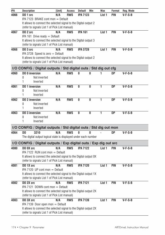
174 • Chapter 9 Parameter ARTDriveL Instruction Manual
IPA Description [Unit] Access Default Min Max Format Reg. Mode
4066 DO 1 src N/A RWS IPA 7123 List 1 PIN V-F-S-BIPA 7123 BRAKE cont mon = DefaultIt allows to connect the selected signal to the Digital output 2(refer to signals List 1 of Pick List manual)
4067 DO 2 src N/A RWS IPA 161 List 1 PIN V-F-S-BIPA 161 Drive ready = DefaultIt allows to connect the selected signal to the Digital output 3(refer to signals List 1 of Pick List manual)
4068 DO 3 src N/A RWS IPA 3728 List 1 PIN V-F-S-BIPA 3728 Speed is zero = DefaultIt allows to connect the selected signal to the Digital output 2(refer to signals List 1 of Pick List manual)
I/O CONFIG / Digital outputs / Std digital outs / Std dig out cfg4060 DO 0 inversion N/A RWS 0 0 1 DP V-F-S-B
0 Not inverted1 Inverted
4061 DO 1 inversion N/A RWS 0 0 1 DP V-F-S-B0 Not inverted1 Inverted
4062 DO 2 inversion N/A RWS 0 0 1 DP V-F-S-B0 Not inverted1 Inverted
4063 DO 3 inversion N/A RWS 0 0 1 DP V-F-S-B0 Not inverted1 Inverted
I/O CONFIG / Digital outputs / Std digital outs / Std dig out mon4064 DO 3210 N/A RWS 0 0 - DP V-F-S-B
The digital output logical state is displayed under each number
I/O CONFIG / Digital outputs / Exp digital outs / Exp dig out src4080 DO 0X src N/A RWS IPA 7122 List 1 PIN V-F-S-B
IPA 7122 RUN cont mon = DefaultIt allows to connect the selected signal to the Digital output 0X(refer to signals List 1 of Pick List manual)
4081 DO 1X src N/A RWS IPA 7120 List 1 PIN V-F-S-BIPA 7120 UP cont mon = DefaultIt allows to connect the selected signal to the Digital output 1X(refer to signals List 1 of Pick List manual)
4082 DO 2X src N/A RWS IPA 7121 List 1 PIN V-F-S-BIPA 7121 DOWN cont mon = DefaultIt allows to connect the selected signal to the Digital output 2X(refer to signals List 1 of Pick List manual)
4083 DO 3X src N/A RWS IPA 7139 List 1 PIN V-F-S-BIPA 7139 Door open mon = DefaultIt allows to connect the selected signal to the Digital output 2X(refer to signals List 1 of Pick List manual)
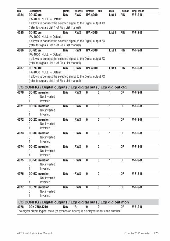
ARTDriveL Instruction Manual Chapter 9 Parameter • 175
IPA Description [Unit] Access Default Min Max Format Reg. Mode4084 DO 4X src N/A RWS IPA 4000 List 1 PIN V-F-S-B
IPA 4000 NULL = DefaultIt allows to connect the selected signal to the Digital output 4X(refer to signals List 1 of Pick List manual)
4085 DO 5X src N/A RWS IPA 4000 List 1 PIN V-F-S-BIPA 4000 NULL = DefaultIt allows to connect the selected signal to the Digital output 5X(refer to signals List 1 of Pick List manual)
4086 DO 6X src N/A RWS IPA 4000 List 1 PIN V-F-S-BIPA 4000 NULL = DefaultIt allows to connect the selected signal to the Digital output 6X(refer to signals List 1 of Pick List manual)
4087 DO 7X src N/A RWS IPA 4000 List 1 PIN V-F-S-BIPA 4000 NULL = DefaultIt allows to connect the selected signal to the Digital output 7X(refer to signals List 1 of Pick List manual)
I/O CONFIG / Digital outputs / Exp digital outs / Exp dig out cfg4070 DO 0X inversion N/A RWS 0 0 1 DP V-F-S-B
0 Not inverted1 Inverted
4071 DO 1X inversion N/A RWS 0 0 1 DP V-F-S-B0 Not inverted1 Inverted
4072 DO 2X inversion N/A RWS 0 0 1 DP V-F-S-B0 Not inverted1 Inverted
4073 DO 3X inversion N/A RWS 0 0 1 DP V-F-S-B0 Not inverted1 Inverted
4074 DO 4X inversion N/A RWS 0 0 1 DP V-F-S-B0 Not inverted1 Inverted
4075 DO 5X inversion N/A RWS 0 0 1 DP V-F-S-B0 Not inverted1 Inverted
4076 DO 6X inversion N/A RWS 0 0 1 DP V-F-S-B0 Not inverted1 Inverted
4077 DO 7X inversion N/A RWS 0 0 1 DP V-F-S-B0 Not inverted1 Inverted
I/O CONFIG / Digital outputs / Exp digital outs / Exp dig out mon4078 DOX 76543210 N/A R 0 0 - DP V-F-S-BThe digital output logical state (of expansion board) is displayed under each number.

176 • Chapter 9 Parameter ARTDriveL Instruction Manual
IPA Description [Unit] Access Default Min Max Format Reg. Mode
I/O CONFIG / Digital outputs / Exp dig out en3903 Exp dig out en N/A RWS 0 0 1 DV V-F-S-B
0 Disabled1 EnabledIt enables the expanded digital outputs
I/O CONFIG / Bits->WordThe Word Composing Block, “Bits->Word”, is useful to communicate, for example, between Drive andAPC card: it is possible to compose a word made of Drive ready, Drive ok, Ref is zero, Speed is zero, bycommunicating on a single word.The Bits->Wordn Block has 16 inputs, where each of them can be connected to a signal; the output of theWord compn Block contains the packed input bits.Two “Bits->Word” blocks are available.
WORD_0BIT_0
BIT_15
BIT_1
BIT_14
W0 comp outWord0 B0 src
Word0 B1 src
Word0 B14 src
Word0 B15 src
WORD_1 W1 comp out
............... .......
I/O CONFIG / Bits->Word / Bits->Word0 src2100 Word0 B0 src N/A RWS IPA 4000 List 1 PIN V-F-S-B
IPA 4000 NULL = DefaultIt allows to connect the Bit 0 signal selected to the Word 0(refer to signals List 1 of Pick List manual)
2101 Word0 B1 src N/A RWS IPA 4000 List 1 PIN V-F-S-BIPA 4000 NULL = DefaultIt allows to connect the Bit 1 signal selected to the Word 0(refer to signals List 1 of Pick List manual)
2102 Word0 B2 src N/A RWS IPA 4000 List 1 PIN V-F-S-BIPA 4000 NULL = DefaultIt allows to connect the Bit 2 signal selected to the Word 0(refer to signals List 1 of Pick List manual)
2103 Word0 B3 src N/A RWS IPA 4000 List 1 PIN V-F-S-BIPA 4000 NULL = DefaultIt allows to connect the Bit 3 signal selected to the Word 0(refer to signals List 1 of Pick List manual)
2104 Word0 B4 src N/A RWS IPA 4000 List 1 PIN V-F-S-BIPA 4000 NULL = DefaultIt allows to connect the Bit 4 signal selected to the Word 0(refer to signals List 1 of Pick List manual)
2105 Word0 B5 src N/A RWS IPA 4000 List 1 PIN V-F-S-BIPA 4000 NULL = DefaultIt allows to connect the Bit 5 signal selected to the Word 0(refer to signals List 1 of Pick List manual)
2106 Word0 B6 src N/A RWS IPA 4000 List 1 PIN V-F-S-BIPA 4000 NULL = DefaultIt allows to connect the Bit 6 signal selected to the Word 0(refer to signals List 1 of Pick List manual)

ARTDriveL Instruction Manual Chapter 9 Parameter • 177
IPA Description [Unit] Access Default Min Max Format Reg. Mode2107 Word0 B7 src N/A RWS IPA 4000 List 1 PIN V-F-S-B
IPA 4000 NULL = DefaultIt allows to connect the Bit 7 signal selected to the Word 0(refer to signals List 1 of Pick List manual)
2108 Word0 B8 src N/A RWS IPA 4000 List 1 PIN V-F-S-BIPA 4000 NULL = DefaultIt allows to connect the Bit 8 signal selected to the Word 0(refer to signals List 1 of Pick List manual)
2109 Word0 B9 src N/A RWS IPA 4000 List 1 PIN V-F-S-BIPA 4000 NULL = DefaultIt allows to connect the Bit 9 signal selected to the Word 0(refer to signals List 1 of Pick List manual)
2110 Word0 B10 src N/A RWS IPA 4000 List 1 PIN V-F-S-BIPA 4000 NULL = DefaultIt allows to connect the Bit 10 signal selected to the Word 0(refer to signals List 1 of Pick List manual)
2111 Word0 B11 src N/A RWS IPA 4000 List 1 PIN V-F-S-BIPA 4000 NULL = DefaultIt allows to connect the Bit 11 signal selected to the Word 0(refer to signals List 1 of Pick List manual)
2112 Word0 B12 src N/A RWS IPA 4000 List 1 PIN V-F-S-BIPA 4000 NULL = DefaultIt allows to connect the Bit 12 signal selected to the Word 0(refer to signals List 1 of Pick List manual)
2113 Word0 B13 src N/A RWS IPA 4000 List 1 PIN V-F-S-BIPA 4000 NULL = DefaultIt allows to connect the Bit 13 signal selected to the Word 0(refer to signals List 1 of Pick List manual)
2114 Word0 B14 src N/A RWS IPA 4000 List 1 PIN V-F-S-BIPA 4000 NULL = DefaultIt allows to connect the Bit 14 signal selected to the Word 0(refer to signals List 1 of Pick List manual)
2115 Word0 B15 src N/A RWS IPA 4000 List 1 PIN V-F-S-BIPA 4000 NULL = DefaultIt allows to connect the Bit 15 signal selected to the Word 0(refer to signals List 1 of Pick List manual)
I/O CONFIG / Bits->Word / Bits->Word0 mon2116 W0 comp out N/A R 0 0 - DV V-F-S-B
Monitor for the hexadecimal output value of “Word 0”
I/O CONFIG / Bits->Word / Bits->Word1 src9340 Word1 B0 src N/A RWS IPA 4000 List 1 PIN V-F-S-B
IPA 4000 NULL = DefaultIt allows to connect the Bit 0 signal selected to the Word 1(refer to signals List 1 of Pick List manual)
9341 Word1 B1 src N/A RWS IPA 4000 List 1 PIN V-F-S-BIPA 4000 NULL = DefaultIt allows to connect the Bit 1 signal selected to the Word 1(refer to signals List 1 of Pick List manual)

178 • Chapter 9 Parameter ARTDriveL Instruction Manual
IPA Description [Unit] Access Default Min Max Format Reg. Mode9342 Word1 B2 src N/A RWS IPA 4000 List 1 PIN V-F-S-B
IPA 4000 NULL = DefaultIt allows to connect the Bit 2 signal selected to the Word 1(refer to signals List 1 of Pick List manual)
9343 Word1 B3 src N/A RWS IPA 4000 List 1 PIN V-F-S-BIPA 4000 NULL = DefaultIt allows to connect the Bit 3 signal selected to the Word 1(refer to signals List 1 of Pick List manual)
9344 Word1 B4 src N/A RWS IPA 4000 List 1 PIN V-F-S-BIPA 4000 NULL = DefaultIt allows to connect the Bit 4 signal selected to the Word 1(refer to signals List 1 of Pick List manual)
9345 Word1 B5 src N/A RWS IPA 4000 List 1 PIN V-F-S-BIPA 4000 NULL = DefaultIt allows to connect the Bit 5 signal selected to the Word 1(refer to signals List 1 of Pick List manual)
9346 Word1 B6 src N/A RWS IPA 4000 List 1 PIN V-F-S-BIPA 4000 NULL = DefaultIt allows to connect the Bit 5 signal selected to the Word 1(refer to signals List 1 of Pick List manual)
9347 Word1 B7 src N/A RWS IPA 4000 List 1 PIN V-F-S-BIPA 4000 NULL = DefaultIt allows to connect the Bit 7 signal selected to the Word 1(refer to signals List 1 of Pick List manual)
9348 Word1 B8 src N/A RWS IPA 4000 List 1 PIN V-F-S-BIPA 4000 NULL = DefaultIt allows to connect the Bit 8 signal selected to the Word 1(refer to signals List 1 of Pick List manual)
9349 Word1 B9 src N/A RWS IPA 4000 List 1 PIN V-F-S-BIPA 4000 NULL = DefaultIt allows to connect the Bit 9 signal selected to the Word 1(refer to signals List 1 of Pick List manual)
9350 Word1 B10 src N/A RWS IPA 4000 List 1 PIN V-F-S-BIPA 4000 NULL = DefaultIt allows to connect the Bit 10 signal selected to the Word 1(refer to signals List 1 of Pick List manual)
9351 Word1 B11 src N/A RWS IPA 4000 List 1 PIN V-F-S-BIPA 4000 NULL = DefaultIt allows to connect the Bit 11 signal selected to the Word 1(refer to signals List 1 of Pick List manual)
9352 Word1 B12 src N/A RWS IPA 4000 List 1 PIN V-F-S-BIPA 4000 NULL = DefaultIt allows to connect the Bit 12 signal selected to the Word 1(refer to signals List 1 of Pick List manual)
9353 Word1 B13 src N/A RWS IPA 4000 List 1 PIN V-F-S-BIPA 4000 NULL = DefaultIt allows to connect the Bit 13 signal selected to the Word 1(refer to signals List 1 of Pick List manual)
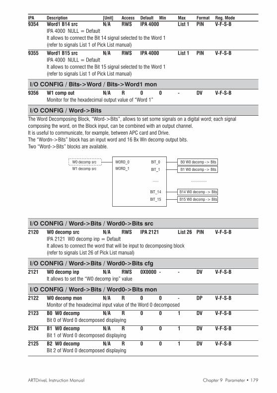
ARTDriveL Instruction Manual Chapter 9 Parameter • 179
IPA Description [Unit] Access Default Min Max Format Reg. Mode9354 Word1 B14 src N/A RWS IPA 4000 List 1 PIN V-F-S-B
IPA 4000 NULL = DefaultIt allows to connect the Bit 14 signal selected to the Word 1(refer to signals List 1 of Pick List manual)
9355 Word1 B15 src N/A RWS IPA 4000 List 1 PIN V-F-S-BIPA 4000 NULL = DefaultIt allows to connect the Bit 15 signal selected to the Word 1(refer to signals List 1 of Pick List manual)
I/O CONFIG / Bits->Word / Bits->Word1 mon9356 W1 comp out N/A R 0 0 - DV V-F-S-B
Monitor for the hexadecimal output value of “Word 1”
I/O CONFIG / Word->BitsThe Word Decomposing Block, “Word->Bits”, allows to set some signals on a digital word; each signalcomposing the word, on the Block input, can be combined with an output channel.It is useful to communicate, for example, between APC card and Drive.The “Wordn->Bits” block has an input word and 16 Bx Wn decomp output bits.Two “Word->Bits” blocks are available.
WORD_0 BIT_0
......
BIT_14
BIT_1
BIT_15
W0 decomp src B0 W0 decomp -> Bits
B15 W0 decomp -> Bits
B14 W0 decomp -> Bits
................
B1 W0 decomp -> BitsWORD_1W1 decomp src
I/O CONFIG / Word->Bits / Word0->Bits src2120 W0 decomp src N/A RWS IPA 2121 List 26 PIN V-F-S-B
IPA 2121 W0 decomp inp = DefaultIt allows to connect the word that will be input to decomposing block(refer to signals List 26 of Pick List manual)
I/O CONFIG / Word->Bits / Word0->Bits cfg2121 W0 decomp inp N/A RWS 0X0000 - - DV V-F-S-B
It allows to set the “W0 decomp inp” value
I/O CONFIG / Word->Bits / Word0->Bits mon2122 W0 decomp mon N/A R 0 0 - DP V-F-S-B
Monitor of the hexadecimal input value of the Word 0 decomposed
2123 B0 W0 decomp N/A R 0 0 1 DV V-F-S-BBit 0 of Word 0 decomposed displaying
2124 B1 W0 decomp N/A R 0 0 1 DV V-F-S-BBit 1 of Word 0 decomposed displaying
2125 B2 W0 decomp N/A R 0 0 1 DV V-F-S-BBit 2 of Word 0 decomposed displaying
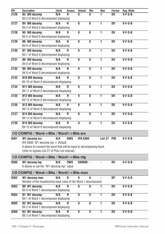
180 • Chapter 9 Parameter ARTDriveL Instruction Manual
IPA Description [Unit] Access Default Min Max Format Reg. Mode2126 B3 W0 decomp N/A R 0 0 1 DV V-F-S-B
Bit 3 of Word 0 decomposed displaying
2127 B4 W0 decomp N/A R 0 0 1 DV V-F-S-BBit 4 of Word 0 decomposed displaying
2128 B5 W0 decomp N/A R 0 0 1 DV V-F-S-BBit 5 of Word 0 decomposed displaying
2129 B6 W0 decomp N/A R 0 0 1 DV V-F-S-BBit 6 of Word 0 decomposed displaying
2130 B7 W0 decomp N/A R 0 0 1 DV V-F-S-BBit 7 of Word 0 decomposed displaying
2131 B8 W0 decomp N/A R 0 0 1 DV V-F-S-BBit 8 of Word 0 decomposed displaying
2132 B9 W0 decomp N/A R 0 0 1 DV V-F-S-BBit 9 of Word 0 decomposed displaying
2133 B10 W0 decomp N/A R 0 0 1 DV V-F-S-BBit 10 of Word 0 decomposed displaying
2134 B11 W0 decomp N/A R 0 0 1 DV V-F-S-BBit 11 of Word 0 decomposed displaying
2135 B12 W0 decomp N/A R 0 0 1 DV V-F-S-BBit 12 of Word 0 decomposed displaying
2136 B13 W0 decomp N/A R 0 0 1 DV V-F-S-BBit 13 of Word 0 decomposed displaying
2137 B14 W0 decomp N/A R 0 0 1 DV V-F-S-BBit 14 of Word 0 decomposed displaying
2138 B15 W0 decomp N/A R 0 0 1 DV V-F-S-BBit 15 of Word 0 decomposed displaying
I/O CONFIG / Word->Bits / Word1->Bits src9361 W1 decomp src N/A RWS IPA 9360 List 27 PIN V-F-S-B
IPA 9360 W1 decomp inp = DefaultIt allows to connect the word that will be input to decomposing block(refer to signals List 27 of Pick List manual)
I/O CONFIG / Word->Bits / Word1->Bits cfg9360 W1 decomp inp N/A RWS 0X0000 - - DV V-F-S-B
It allows to set the “W1 decomp inp” value
I/O CONFIG / Word->Bits / Word1->Bits mon9362 W1 decomp mon N/A R 0 0 - DP V-F-S-B
Monitor of the hexadecimal input value of the Word 1 decomposed
9363 B0 W1 decomp N/A R 0 0 1 DV V-F-S-BBit 0 of Word 1 decomposed displaying
9364 B1 W1 decomp N/A R 0 0 1 DV V-F-S-BBit 1 of Word 1 decomposed displaying
9365 B2 W1 decomp N/A R 0 0 1 DV V-F-S-BBit 2 of Word 1 decomposed displaying
9366 B3 W1 decomp N/A R 0 0 1 DV V-F-S-BBit 3 of Word 1 decomposed displaying

ARTDriveL Instruction Manual Chapter 9 Parameter • 181
IPA Description [Unit] Access Default Min Max Format Reg. Mode
9367 B4 W1 decomp N/A R 0 0 1 DV V-F-S-BBit 4 of Word 1 decomposed displaying
9368 B5 W1 decomp N/A R 0 0 1 DV V-F-S-BBit 5 of Word 1 decomposed displaying
9369 B6 W1 decomp N/A R 0 0 1 DV V-F-S-BBit 6 of Word 1 decomposed displaying
9370 B7 W1 decomp N/A R 0 0 1 DV V-F-S-BBit 7 of Word 1 decomposed displaying
9371 B8 W1 decomp N/A R 0 0 1 DV V-F-S-BBit 8 of Word 1 decomposed displaying
9372 B9 W1 decomp N/A R 0 0 1 DV V-F-S-BBit 9 of Word 1 decomposed displaying
9373 B10 W1 decomp N/A R 0 0 1 DV V-F-S-BBit 10 of Word 1 decomposed displaying
9374 B11 W1 decomp N/A R 0 0 1 DV V-F-S-BBit 11 of Word 1 decomposed displaying
9375 B12 W1 decomp N/A R 0 0 1 DV V-F-S-BBit 12 of Word 1 decomposed displaying
9376 B13 W1 decomp N/A R 0 0 1 DV V-F-S-BBit 13 of Word 1 decomposed displaying
9377 B14 W1 decomp N/A R 0 0 1 DV V-F-S-BBit 14 of Word 1 decomposed displaying
9378 B15 W1 decomp N/A R 0 0 1 DV V-F-S-BBit 15 of Word 1 decomposed displaying
SAVE PARAMETERSAVyL drive allows two different commands to save the parameters modified in the regulation mode selected:• by STARTUP menu, “Save Config?” command• by all other menus, “SAVE PARAMETERS” commandAny changes made in STARTUP menu require “Save Config?” command, which saves all entire regulation mode selected.It is recommended every time the user made any changes into STARTUP menu.“SAVE PARAMETERS” command saves all the changes made out of STARTUP menu only.When on the keypad display appears blinking message “Use Save Config”, use “Save Config?” command
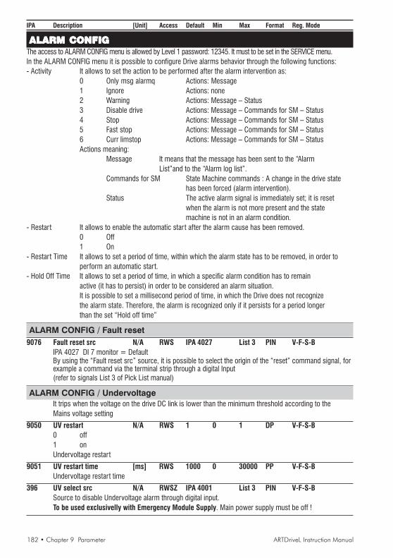
182 • Chapter 9 Parameter ARTDriveL Instruction Manual
IPA Description [Unit] Access Default Min Max Format Reg. Mode
ALARM CONFIGALARM CONFIGALARM CONFIGALARM CONFIGALARM CONFIGThe access to ALARM CONFIG menu is allowed by Level 1 password: 12345. It must to be set in the SERVICE menu.In the ALARM CONFIG menu it is possible to configure Drive alarms behavior through the following functions:- Activity It allows to set the action to be performed after the alarm intervention as:
0 Only msg alarmq Actions: Message1 Ignore Actions: none2 Warning Actions: Message – Status3 Disable drive Actions: Message – Commands for SM – Status4 Stop Actions: Message – Commands for SM – Status5 Fast stop Actions: Message – Commands for SM – Status6 Curr limstop Actions: Message – Commands for SM – StatusActions meaning:
Message It means that the message has been sent to the “AlarmList”and to the “Alarm log list”.
Commands for SM State Machine commands : A change in the drive statehas been forced (alarm intervention).
Status The active alarm signal is immediately set; it is resetwhen the alarm is not more present and the statemachine is not in an alarm condition.
- Restart It allows to enable the automatic star t after the alarm cause has been removed.0 Off1 On
- Restart Time It allows to set a period of time, within which the alarm state has to be removed, in order toperform an automatic start.
- Hold Off Time It allows to set a period of time, in which a specific alarm condition has to remainactive (it has to persist) in order to be considered an alarm situation.It is possible to set a millisecond period of time, in which the Drive does not recognizethe alarm state. Therefore, the alarm is recognized only if it persists for a period longerthan the set “Hold off time”
ALARM CONFIG / Fault reset9076 Fault reset src N/A RWS IPA 4027 List 3 PIN V-F-S-B
IPA 4027 DI 7 monitor = DefaultBy using the “Fault reset src” source, it is possible to select the origin of the “reset” command signal, forexample a command via the terminal strip through a digital Input(refer to signals List 3 of Pick List manual)
ALARM CONFIG / UndervoltageIt trips when the voltage on the drive DC link is lower than the minimum threshold according to theMains voltage setting
9050 UV restart N/A RWS 1 0 1 DP V-F-S-B0 off1 onUndervoltage restart
9051 UV restart time [ms] RWS 1000 0 30000 PP V-F-S-BUndervoltage restart time
396 UV select src N/A RWSZ IPA 4001 List 3 PIN V-F-S-BSource to disable Undervoltage alarm through digital input.To be used exclusivelly with Emergency Module Supply. Main power supply must be off !

ARTDriveL Instruction Manual Chapter 9 Parameter • 183
IPA Description [Unit] Access Default Min Max Format Reg. Mode
ALARM CONFIG / OvervoltageIt trips when the voltage on the drive DC link is higher than the maximum threshold according to theMains voltage setting
9052 OV restart N/A RWS 0 0 1 DP V-F-S-B0 off1 onOvervoltage restart
9053 OV restart time [ms] RWS 1000 0 30000 PP V-F-S-BOvervoltage restart time
ALARM CONFIG / IGBT desaturatIt trips when the IGBT instantaneous overcurrent is detected by gate desaturation sensing circuit
9046 DS restart N/A RWS 0 0 1 DP V-F-S-B0 off1 onIGBT desaturation restart
9047 DS restart time [ms] RWS 1000 0 30000 PP V-F-S-BIGBT desaturation restart time
ALARM CONFIG / Inst overcurrentIt trips when the IGBT instantaneous overcurrent is detected by output current sensor
9063 IOC restart N/A RWS 0 0 1 DP V-F-S-B0 off1 onInstantaneous overcurrent restart
9064 IOC restart time [ms] RWS 1000 0 30000 PP V-F-S-BInstantaneous overcurrent restart time
ALARM CONFIG / Ground faultIt trips when the output phase discharge to ground
9640 GF activity N/A RWS 2 1 6 DP V-F-S-B1 Ignore2 Warning3 Disable drive4 Stop5 Fast stop6 Curr limstpGround fault activity
9641 GF threshold [A] RWS D.Size Calc D.Size PP V-F-S-BGround fault threshold
ALARM CONFIG / External faultIt trips when the External fault input is active
9075 EF src N/A RWS IPA 4023 List 3 PIN V-F-S-BIPA 4000 NULL = DefaultIt allows to connect the External fault input terminal strip(refer to signals List 3 of Pick List manual)
9060 EF activity N/A RWS 3 2 6 DP V-F-S-B1 Ignore2 Warning

184 • Chapter 9 Parameter ARTDriveL Instruction Manual
IPA Description [Unit] Access Default Min Max Format Reg. Mode
3 Disable drive4 Stop5 Fast stop6 Curr limstpExternal fault activity
9061 EF restart N/A RWS 0 0 1 DP V-F-S-B0 off1 onExternal fault restart
9062 EF restart time [ms] RWS 1000 0 30000 PP V-F-S-BExternal fault restart time
9600 EF hold off [ms] RWS 0 0 30000 PP V-F-S-BExternal fault hold off
ALARM CONFIG / Motor OTMotor Over-Temperature indicated via thermal contact or PTC thermistor on78-79 drive regulation board terminals
9065 MOT activity N/A RWS 2 2 6 DP V-F-S-B2 Warning3 Disable drive4 Stop5 Fast stop6 Curr limstpMotor Over-Temperature activity
9066 MOT restart N/A RWS 0 0 1 DP V-F-S-B0 off1 onMotor Over-Temperature restart
9067 MOT restart time [ms] RWS 1000 0 30000 PP V-F-S-BMotor Over-Temperature restart time
9603 MOT hold off [ms] RWS 1000 0 30000 PP V-F-S-BMotor Over-Temperature hold off
ALARM CONFIG / Heatsink S OTHeatsink Sensor Over-Temperature (detected by a sensor)
9054 HTS activity N/A RWS 3 2 6 DP V-F-S-B2 Warning3 Disable drive4 Stop5 Fast stop6 Curr limstpHeatsink Sensor Over-Temperature activity
9055 HTS restart N/A RWS 0 0 1 DP V-F-S-B0 off1 onHeatsink Sensor Over-Temperature restart
9056 HTS restart time [ms] RWS 1000 0 30000 PP V-F-S-BHeatsink Sensor Over-Temperature restart time
9604 HTS hold off [ms] RWS 1000 0 30000 PP V-F-S-BHeatsink Sensor Over-Temperature hold off

ARTDriveL Instruction Manual Chapter 9 Parameter • 185
IPA Description [Unit] Access Default Min Max Format Reg. Mode
ALARM CONFIG / Regulation S OTRegulation card Sensor Over-Temperature
9057 RGS activity N/A RWS 3 2 6 DP V-F-S-B2 Warning3 Disable drive4 Stop5 Fast stop6 Curr limstpRegulation card Sensor Over-Temperature activity
9058 RGS restart N/A RWS 0 0 1 DP V-F-S-B0 off1 onRegulation card Sensor Over-Temperature restart
9059 RGS restart time [ms] RWS 1000 0 30000 PP V-F-S-BRegulation card Sensor Over-Temperature restart time
9605 RGS hold off [ms] RWS 10000 0 30000 PP V-F-S-BRegulation card Sensor Over-Temperature hold off
ALARM CONFIG / Intake air S OTIntake air Sensor Over-Temperature (only for model AVyL 4185 and over)
9087 IAS activity N/A RWS 3 2 6 DP V-F-S-B2 Warning3 Disable drive4 Stop5 Fast stop6 Curr limstpIntake air Sensor Over-Temperature activity
9088 IAS restart N/A RWS 0 0 1 DP V-F-S-B0 off1 onIntake air Sensor Over-Temperature restart
9089 IAS restart time [ms] RWS 1000 0 30000 PP V-F-S-BIntake air Sensor Over-Temperature restart time
9606 IAS hold off [ms] RWS 10000 0 30000 PP V-F-S-BIntake air Sensor Over-Temperature hold off
ALARM CONFIG / Contact feedbackIt trips when the contact feedback signal is not detected .Can be used to monitor the status of output contactor and give alarm if command and feedback don’t match.
Digital output
set as RUN cont mon
Digital input
CNT feedback src set as Digital input X
K1MK2M
OUTPUT CONTACTOR
AUXCONTACTS
MAIN CONTACTS
7141 CNT feedback src N/A RWS IPA 7122 List 3 PIN V-F-S-BIPA 7122 RUN cont mon = DefaultIt allows to select the origin of Contact feedback signal(refer to signals List 3 of Pick List manual)
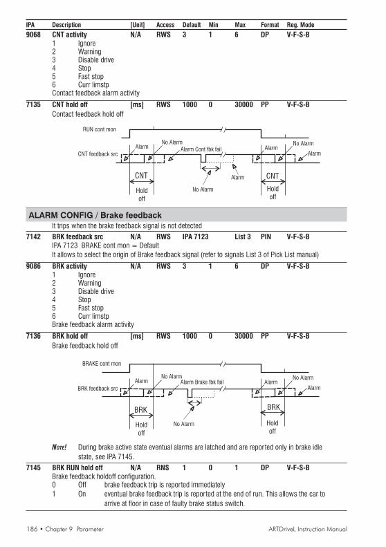
186 • Chapter 9 Parameter ARTDriveL Instruction Manual
IPA Description [Unit] Access Default Min Max Format Reg. Mode
9068 CNT activity N/A RWS 3 1 6 DP V-F-S-B1 Ignore2 Warning3 Disable drive4 Stop5 Fast stop6 Curr limstpContact feedback alarm activity
7135 CNT hold off [ms] RWS 1000 0 30000 PP V-F-S-BContact feedback hold off
RUN cont mon
CNT feedback src
AlarmNo Alarm
Alarm Cont fbk fail AlarmNo Alarm
Alarm
CNT
Holdoff
Holdoff
CNT
No Alarm
Alarm
ALARM CONFIG / Brake feedbackIt trips when the brake feedback signal is not detected
7142 BRK feedback src N/A RWS IPA 7123 List 3 PIN V-F-S-BIPA 7123 BRAKE cont mon = DefaultIt allows to select the origin of Brake feedback signal (refer to signals List 3 of Pick List manual)
9086 BRK activity N/A RWS 3 1 6 DP V-F-S-B1 Ignore2 Warning3 Disable drive4 Stop5 Fast stop6 Curr limstpBrake feedback alarm activity
7136 BRK hold off [ms] RWS 1000 0 30000 PP V-F-S-BBrake feedback hold off
BRAKE cont mon
BRK feedback src
AlarmNo Alarm
AlarmNo Alarm
Alarm
BRK
Holdoff
Holdoff
BRK
Alarm Brake fbk fail
No Alarm
NOTE! During brake active state eventual alarms are latched and are reported only in brake idlestate, see IPA 7145.
7145 BRK RUN hold off N/A RNS 1 0 1 DP V-F-S-BBrake feedback holdoff configuration.0 Off brake feedback trip is reported immediately1 On eventual brake feedback trip is reported at the end of run. This allows the car to
arrive at floor in case of faulty brake status switch.
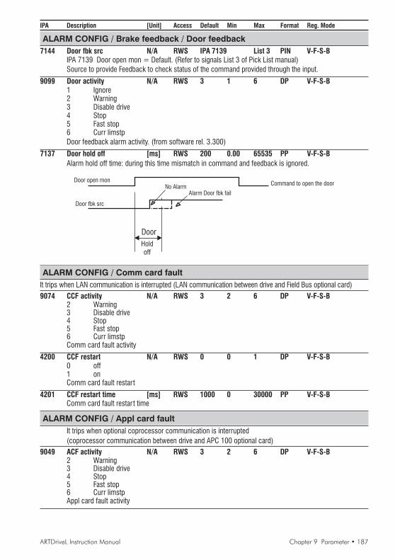
ARTDriveL Instruction Manual Chapter 9 Parameter • 187
IPA Description [Unit] Access Default Min Max Format Reg. Mode
ALARM CONFIG / Brake feedback / Door feedback7144 Door fbk src N/A RWS IPA 7139 List 3 PIN V-F-S-B
IPA 7139 Door open mon = Default. (Refer to signals List 3 of Pick List manual)Source to provide Feedback to check status of the command provided through the input.
9099 Door activity N/A RWS 3 1 6 DP V-F-S-B1 Ignore2 Warning3 Disable drive4 Stop5 Fast stop6 Curr limstpDoor feedback alarm activity. (from software rel. 3.300)
7137 Door hold off [ms] RWS 200 0.00 65535 PP V-F-S-BAlarm hold off time: during this time mismatch in command and feedback is ignored.
Door open mon
Door fbk src
No AlarmAlarm Door fbk fail
Holdoff
Door
Command to open the door
ALARM CONFIG / Comm card faultIt trips when LAN communication is interrupted (LAN communication between drive and Field Bus optional card)
9074 CCF activity N/A RWS 3 2 6 DP V-F-S-B2 Warning3 Disable drive4 Stop5 Fast stop6 Curr limstpComm card fault activity
4200 CCF restart N/A RWS 0 0 1 DP V-F-S-B0 off1 onComm card fault restart
4201 CCF restart time [ms] RWS 1000 0 30000 PP V-F-S-BComm card fault restar t time
ALARM CONFIG / Appl card faultIt trips when optional coprocessor communication is interrupted(coprocessor communication between drive and APC 100 optional card)
9049 ACF activity N/A RWS 3 2 6 DP V-F-S-B2 Warning3 Disable drive4 Stop5 Fast stop6 Curr limstpAppl card fault activity

188 • Chapter 9 Parameter ARTDriveL Instruction Manual
IPA Description [Unit] Access Default Min Max Format Reg. Mode
ALARM CONFIG / Drive overloadIt trips when Drive overload accumulator exceeded trip threshold
9040 DOL activity N/A RWS 1 1 6 DP V-F-S-B1 Ignore2 Warning3 Disable drive4 Stop5 Fast stop6 Curr limstpDrive overload activity
ALARM CONFIG / Motor overloadIt trips when Motor overload accumulator exceeded trip threshold
9041 MOL activity N/A RWS 2 1 6 DP V-F-S-B1 Ignore2 Warning3 Disable drive4 Stop5 Fast stop6 Curr limstp
ALARM CONFIG / BU overloadIt trips when Brake resistor overload accumulator exceeded trip threshold
9071 BUOL activity N/A RWS 3 1 6 DP V-F-S-B2 Warning3 Disable drive4 Stop5 Fast stop6 Curr limstpBraking Unit overload activity
ALARM CONFIG / OverspeedIt trips when the speed of the motor exceeded speed limit threshold
9220 OS activity N/A RWS 3 1 6 DP V-F-S-B2 Warning3 Disable drive4 Stop5 Fast stop6 Curr limstpOverspeed activity
9221 OS threshold [rmp] RWS Calc 0.00 8192 PP V-F-S-BOverspeed threshold
9608 OS hold off [ms] RWS 0 0 30000 PP V-F-S-BOverspeed hold off
ALARM CONFIG / Spd fbk lossIt trips when the speed feedback is not detected or encoder supply failed
9042 SFL activity N/A RWS 3 1 6 DP V-F-S-B1 Ignore2 Warning3 Disable drive4 Stop5 Fast stop6 Curr limstpSpd fbk loss activity
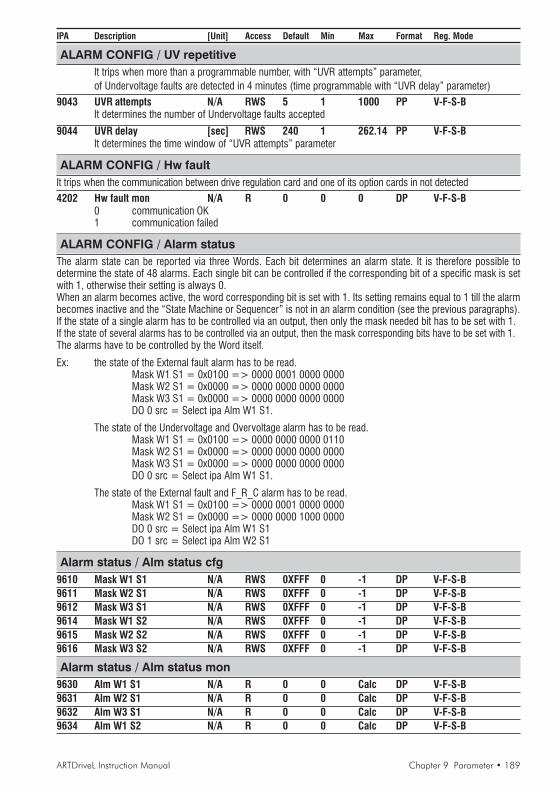
ARTDriveL Instruction Manual Chapter 9 Parameter • 189
IPA Description [Unit] Access Default Min Max Format Reg. Mode
ALARM CONFIG / UV repetitiveIt trips when more than a programmable number, with “UVR attempts” parameter,of Undervoltage faults are detected in 4 minutes (time programmable with “UVR delay” parameter)
9043 UVR attempts N/A RWS 5 1 1000 PP V-F-S-BIt determines the number of Undervoltage faults accepted
9044 UVR delay [sec] RWS 240 1 262.14 PP V-F-S-BIt determines the time window of “UVR attempts” parameter
ALARM CONFIG / Hw faultIt trips when the communication between drive regulation card and one of its option cards in not detected4202 Hw fault mon N/A R 0 0 0 DP V-F-S-B
0 communication OK1 communication failed
ALARM CONFIG / Alarm statusThe alarm state can be reported via three Words. Each bit determines an alarm state. It is therefore possible todetermine the state of 48 alarms. Each single bit can be controlled if the corresponding bit of a specific mask is setwith 1, otherwise their setting is always 0.When an alarm becomes active, the word corresponding bit is set with 1. Its setting remains equal to 1 till the alarmbecomes inactive and the “State Machine or Sequencer” is not in an alarm condition (see the previous paragraphs).If the state of a single alarm has to be controlled via an output, then only the mask needed bit has to be set with 1.If the state of several alarms has to be controlled via an output, then the mask corresponding bits have to be set with 1.The alarms have to be controlled by the Word itself.
Ex: the state of the External fault alarm has to be read.Mask W1 S1 = 0x0100 => 0000 0001 0000 0000Mask W2 S1 = 0x0000 => 0000 0000 0000 0000Mask W3 S1 = 0x0000 => 0000 0000 0000 0000DO 0 src = Select ipa Alm W1 S1.
The state of the Undervoltage and Overvoltage alarm has to be read.Mask W1 S1 = 0x0100 => 0000 0000 0000 0110Mask W2 S1 = 0x0000 => 0000 0000 0000 0000Mask W3 S1 = 0x0000 => 0000 0000 0000 0000DO 0 src = Select ipa Alm W1 S1.
The state of the External fault and F_R_C alarm has to be read.Mask W1 S1 = 0x0100 => 0000 0001 0000 0000Mask W2 S1 = 0x0000 => 0000 0000 1000 0000DO 0 src = Select ipa Alm W1 S1DO 1 src = Select ipa Alm W2 S1
Alarm status / Alm status cfg9610 Mask W1 S1 N/A RWS 0XFFF 0 -1 DP V-F-S-B9611 Mask W2 S1 N/A RWS 0XFFF 0 -1 DP V-F-S-B9612 Mask W3 S1 N/A RWS 0XFFF 0 -1 DP V-F-S-B9614 Mask W1 S2 N/A RWS 0XFFF 0 -1 DP V-F-S-B9615 Mask W2 S2 N/A RWS 0XFFF 0 -1 DP V-F-S-B9616 Mask W3 S2 N/A RWS 0XFFF 0 -1 DP V-F-S-B
Alarm status / Alm status mon9630 Alm W1 S1 N/A R 0 0 Calc DP V-F-S-B9631 Alm W2 S1 N/A R 0 0 Calc DP V-F-S-B9632 Alm W3 S1 N/A R 0 0 Calc DP V-F-S-B9634 Alm W1 S2 N/A R 0 0 Calc DP V-F-S-B
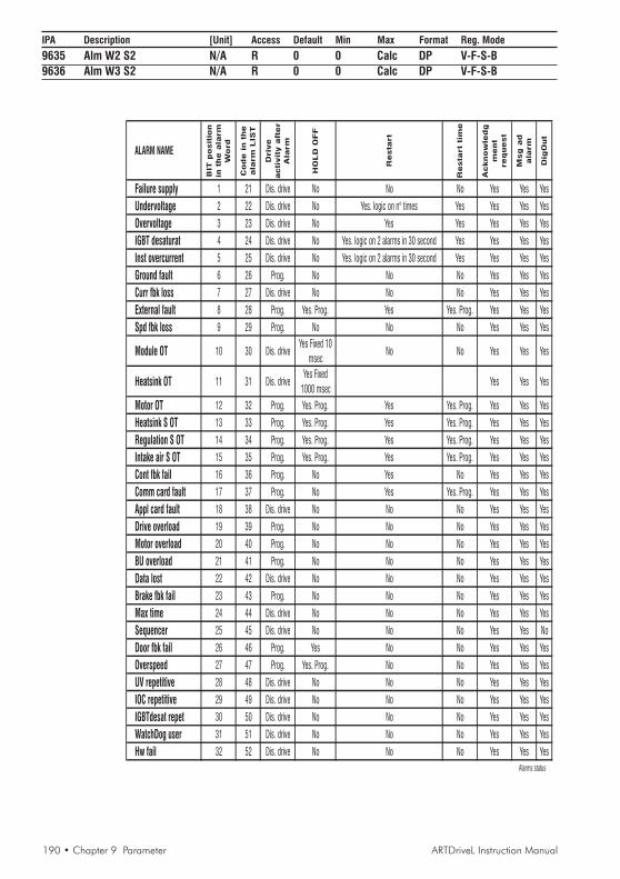
190 • Chapter 9 Parameter ARTDriveL Instruction Manual
IPA Description [Unit] Access Default Min Max Format Reg. Mode
9635 Alm W2 S2 N/A R 0 0 Calc DP V-F-S-B9636 Alm W3 S2 N/A R 0 0 Calc DP V-F-S-B
ALARM NAME
BIT
posit
ion
inth
eala
rm
Word
Code
inth
e
ala
rm
LIS
T
Driv
e
acti
vit
yaft
er
Ala
rm
HO
LD
OFF
Resta
rt
Resta
rt
tim
e
Acknow
ledg
ment
request
Msg
ad
ala
rm
Dig
Out
Failure supply 1 21 Dis. drive No No No Yes Yes Yes
Undervoltage 2 22 Dis. drive No Yes. logic on n° times Yes Yes Yes Yes
Overvoltage 3 23 Dis. drive No Yes Yes Yes Yes Yes
IGBT desaturat 4 24 Dis. drive No Yes. logic on 2 alarms in 30 second Yes Yes Yes Yes
Inst overcurrent 5 25 Dis. drive No Yes. logic on 2 alarms in 30 second Yes Yes Yes Yes
Ground fault 6 26 Prog. No No No Yes Yes Yes
Curr fbk loss 7 27 Dis. drive No No No Yes Yes Yes
External fault 8 28 Prog. Yes. Prog. Yes Yes. Prog. Yes Yes Yes
Spd fbk loss 9 29 Prog. No No No Yes Yes Yes
Module OT 10 30 Dis. driveYes Fixed 10
msecNo No Yes Yes Yes
Heatsink OT 11 31 Dis. driveYes Fixed
1000 msecYes Yes Yes
Motor OT 12 32 Prog. Yes. Prog. Yes Yes. Prog. Yes Yes Yes
Heatsink S OT 13 33 Prog. Yes. Prog. Yes Yes. Prog. Yes Yes Yes
Regulation S OT 14 34 Prog. Yes. Prog. Yes Yes. Prog. Yes Yes Yes
Intake air S OT 15 35 Prog. Yes. Prog. Yes Yes. Prog. Yes Yes Yes
Cont fbk fail 16 36 Prog. No Yes No Yes Yes Yes
Comm card fault 17 37 Prog. No Yes Yes. Prog. Yes Yes Yes
Appl card fault 18 38 Dis. drive No No No Yes Yes Yes
Drive overload 19 39 Prog. No No No Yes Yes Yes
Motor overload 20 40 Prog. No No No Yes Yes Yes
BU overload 21 41 Prog. No No No Yes Yes Yes
Data lost 22 42 Dis. drive No No No Yes Yes Yes
Brake fbk fail 23 43 Prog. No No No Yes Yes Yes
Max time 24 44 Dis. drive No No No Yes Yes Yes
Sequencer 25 45 Dis. drive No No No Yes Yes No
Door fbk fail 26 46 Prog. Yes No No Yes Yes Yes
Overspeed 27 47 Prog. Yes. Prog. No No Yes Yes Yes
UV repetitive 28 48 Dis. drive No No No Yes Yes Yes
IOC repetitive 29 49 Dis. drive No No No Yes Yes Yes
IGBTdesat repet 30 50 Dis. drive No No No Yes Yes Yes
WatchDog user 31 51 Dis. drive No No No Yes Yes Yes
Hw fail 32 52 Dis. drive No No No Yes Yes Yes
Alarms status

ARTDriveL Instruction Manual Chapter 9 Parameter • 191
IPA Description [Unit] Access Default Min Max Format Reg. Mode
COMMUNICACOMMUNICACOMMUNICACOMMUNICACOMMUNICATIONTIONTIONTIONTIONThe access to COMMUNICATION menu is allowed by Level 1 password: 12345. It must be set in the SERVICE menu.
RS485: The communication protocol can be chosen between Slink4, Modbus, Jbus or ISO 1745 through the“Protocol type” parameter. Each of these protocols allow a multipoint network. See the specific protocol manual forfurther details.The Drive address can be defined via the “Slave address” parameter. Editing parameter 105, “Slave address”, and saving thenew value perform the address change. The new address becomes active after the Drive has been switched off and then backon. A temporary address change is also possible when using the Slink4 protocol with an Slink4 command.When using the Slink4 protocol, the RS485 serial line operates in half-duplex, where the data cannot be transmittedand received simultaneously. It is sometimes possible during the transition from transmission to reception modes,the Master (PC or PLC) reaches the reception condition after the Drive has already started to send its datapackage. As a consequence, the package received by the master is not correct. In order to avoid suchoccurrences, the “Slave res time” parameter can be adjusted to delay the drive response so the Master hassample mode switching time. This situation does not occur with the Modbus and Jbus protocols as thesynchronization pause between messages is specified by the protocol and is guaranteed.
SBI: The communication with the SBI Field Bus option cards (Serial Bus Interface) is performed via two channels:· Synchronous or Process channel (PDC Process Data Channel) for a cyclical value interchange.· Asynchronous or Configuration channel for a low priority access to all the Drive parameters.
As for the data exchange modes between the SBI card and the Network see the SBI card documentation.The process data exchange between the Drive and the SBI has the following structure:
- the interface is made of six writing Words and six reading Words.- the source Drive parameter has to be defined for the six Words: “Drv -> SBI word” transmitting the data from the Drive to the SBI.- Six Words move the data from the SBI to the Drive: “SBI -> Drv word”
For more information to see the following documents for related information on SBI:SBI-PDP 33 Interface card Profibus- DP instruction manualSBI-DN 33 DeviceNet card instruction manualSBI-COP CANopen card instruction manual
COMMUNICATION / RS485105 Slave address N/A RWS 1 0 255 DK V-F-S-B
It define the drive slave address
106 Slave res time N/A RWS 1 0 255 DK V-F-S-BIt define the drive slave address time
104 Protocol type N/A RWS 0 0 2 DK V-F-S-B0 Slink 41 Modbus2 Jbus3 ISO 17454 Hiperface protocol(Used to communicate with Stegmann absolute encoders)It defines the drive communication protocol type
COMMUNICATION / SBI config8999 SBI enable N/A RWS 0 0 1 DK V-F-S-B
0 Disabled1 EnabledIt allows to enable SBI Field Bus option cards(SAVE PARAMETERS command and drive recycle power are required)

192 • Chapter 9 Parameter ARTDriveL Instruction Manual
IPA Description [Unit] Access Default Min Max Format Reg. Mode
COMMUNICATION / SBI monitor8998 Last SBI error N/A R 0 0 2 DP V-F-S-B
It defines the last found error:0 = OK (no error)1 = Hardware fault2 = Bus Loss
COMMUNICATION / Drv->SBI word
COMMUNICATION / Drv->SBI word / Drv->SBI W src9010 Drv SBI W0 src N/A RWS IPA 9020 List 40 PIN V-F-S-B
IPA 9020 Int Drv SBI W0 = DefaultIt allows to select the origin of Word 0 to be transmitted from Drive to SBI card(refer to signals List 40 of Pick List manual)
9011 Drv SBI W1 src N/A RWS IPA 9021 List 40 PIN V-F-S-BIPA 9021 Int Drv SBI W1 = DefaultIt allows to select the origin of Word 1 to be transmitted from Drive to SBI card(refer to signals List 40 of Pick List manual)
9012 Drv SBI W2 src N/A RWS IPA 9022 List 40 PIN V-F-S-BIPA 9022 Int Drv SBI W2 = DefaultIt allows to select the origin of Word 2 to be transmitted from Drive to SBI card(refer to signals List 40 of Pick List manual)
9013 Drv SBI W3 src N/A RWS IPA 9023 List 40 PIN V-F-S-BIPA 9023 Int Drv SBI W3 = DefaultIt allows to select the origin of Word 3 to be transmitted from Drive to SBI card(refer to signals List 40 of Pick List manual)
9014 Drv SBI W4 src N/A RWS IPA 9024 List 40 PIN V-F-S-BIPA 9024 Int Drv SBI W4 = DefaultIt allows to select the origin of Word 4 to be transmitted from Drive to SBI card(refer to signals List 40 of Pick List manual)
9015 Drv SBI W5 src N/A RWS IPA 9025 List 40 PIN V-F-S-BIPA 9025 Int Drv SBI W5 = DefaultIt allows to select the origin of Word 5 to be transmitted from Drive to SBI card(refer to signals List 40 of Pick List manual)
COMMUNICATION / Drv->SBI word / Drv->SBI W cfg9020 Int Drv SBI W0 N/A RWS 0.00 - - PV V-F-S-B
Internal Word 0 value configuration (default connected to Drv SBI W0 src)
9021 Int Drv SBI W1 N/A RWS 0.00 - - PV V-F-S-BInternal Word 1 value configuration (default connected to Drv SBI W1 src)
9022 Int Drv SBI W2 N/A RWS 0.00 - - PV V-F-S-BInternal Word 2 value configuration (default connected to Drv SBI W2 src)
9023 Int Drv SBI W3 N/A RWS 0.00 - - PV V-F-S-BInternal Word 3 value configuration (default connected to Drv SBI W3 src)
9024 Int Drv SBI W4 N/A RWS 0.00 - - PV V-F-S-BInternal Word 4 value configuration (default connected to Drv SBI W4 src)
9025 Int Drv SBI W5 N/A RWS 0.00 - - PV V-F-S-BInternal Word 5 value configuration (default connected to Drv SBI W5 src)
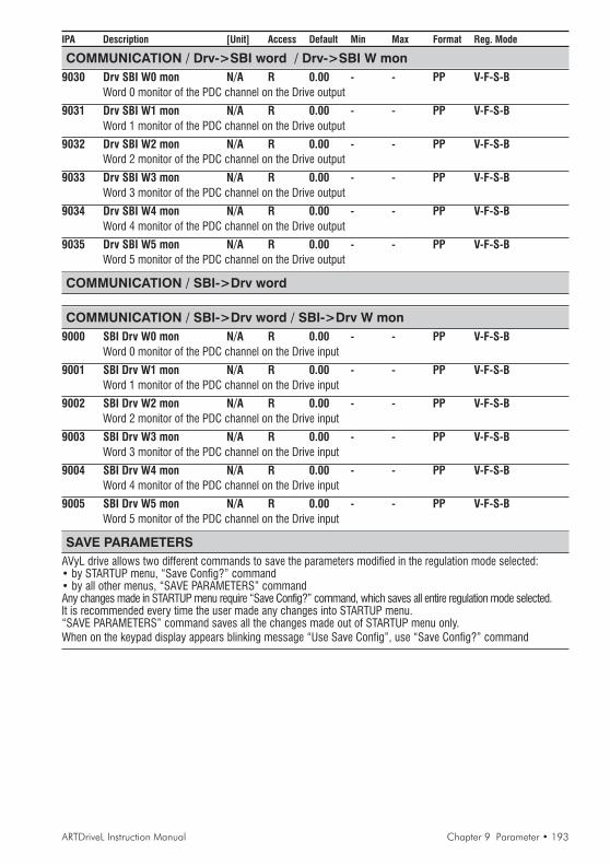
ARTDriveL Instruction Manual Chapter 9 Parameter • 193
IPA Description [Unit] Access Default Min Max Format Reg. Mode
COMMUNICATION / Drv->SBI word / Drv->SBI W mon9030 Drv SBI W0 mon N/A R 0.00 - - PP V-F-S-B
Word 0 monitor of the PDC channel on the Drive output
9031 Drv SBI W1 mon N/A R 0.00 - - PP V-F-S-BWord 1 monitor of the PDC channel on the Drive output
9032 Drv SBI W2 mon N/A R 0.00 - - PP V-F-S-BWord 2 monitor of the PDC channel on the Drive output
9033 Drv SBI W3 mon N/A R 0.00 - - PP V-F-S-BWord 3 monitor of the PDC channel on the Drive output
9034 Drv SBI W4 mon N/A R 0.00 - - PP V-F-S-BWord 4 monitor of the PDC channel on the Drive output
9035 Drv SBI W5 mon N/A R 0.00 - - PP V-F-S-BWord 5 monitor of the PDC channel on the Drive output
COMMUNICATION / SBI->Drv word
COMMUNICATION / SBI->Drv word / SBI->Drv W mon9000 SBI Drv W0 mon N/A R 0.00 - - PP V-F-S-B
Word 0 monitor of the PDC channel on the Drive input
9001 SBI Drv W1 mon N/A R 0.00 - - PP V-F-S-BWord 1 monitor of the PDC channel on the Drive input
9002 SBI Drv W2 mon N/A R 0.00 - - PP V-F-S-BWord 2 monitor of the PDC channel on the Drive input
9003 SBI Drv W3 mon N/A R 0.00 - - PP V-F-S-BWord 3 monitor of the PDC channel on the Drive input
9004 SBI Drv W4 mon N/A R 0.00 - - PP V-F-S-BWord 4 monitor of the PDC channel on the Drive input
9005 SBI Drv W5 mon N/A R 0.00 - - PP V-F-S-BWord 5 monitor of the PDC channel on the Drive input
SAVE PARAMETERSAVyL drive allows two different commands to save the parameters modified in the regulation mode selected:• by STARTUP menu, “Save Config?” command• by all other menus, “SAVE PARAMETERS” commandAny changes made in STARTUP menu require “Save Config?” command, which saves all entire regulation mode selected.It is recommended every time the user made any changes into STARTUP menu.“SAVE PARAMETERS” command saves all the changes made out of STARTUP menu only.When on the keypad display appears blinking message “Use Save Config”, use “Save Config?” command

194 • Chapter 9 Parameter ARTDriveL Instruction Manual
IPA Description [Unit] Access Default Min Max Format Reg. Mode
APPL CARD CONFIGAPPL CARD CONFIGAPPL CARD CONFIGAPPL CARD CONFIGAPPL CARD CONFIGThe access to APPL CARD CONFIG menu is allowed by Level 1 password: 12345. It must to be set in theSERVICE menu.APC option card is used for advanced lift applications.The communication between the Drive and the APC is performed via two channels for each direction.
· from drive to APC: “Drv->DGFCS” writing to drive 5 Synchronous words“Drv->DGFCA” writing to drive 10 Asynchronous words
· from APC to drive: “DGFCS->Drv” reading from APC 5 Synchronous words“DGFCA->Drv” reading from APC 10 Asynchronous words
The Words move the data from the APC to the Drive can be found in the source selecting lists.For more information following the instructions on DGFC-386y-1 card (APC100 card) manual
APPL CARD CONFIG / DGFC / DGFC config4129 DGFC enable N/A RWS 0 0 1 DK V-F-S-B
0 Disabled1 EnabledIt allows to enable APC option cards(SAVE PARAMETERS command and drive recycle power are required)
APPL CARD CONFIG / DGFC / DGFC sync Ch
APPL CARD CONFIG / DGFC / Drv->DGFCS W src4100 Drv DGFC-S W0src N/A RWS IPA 4105 List 29 PIN V-F-S-B
IPA 4105 Int DrvDGFC-S W0 = DefaultIt allows to select the origin of Synchronous Word 0 to be transmitted from Drive to APC card(refer to signals List 29 of Pick List manual)
4101 Drv DGFC-S W1src N/A RWS IPA 4106 List 29 PIN V-F-S-BIPA 4106 Int DrvDGFC-S W1 = DefaultIt allows to select the origin of Synchronous Word 1 to be transmitted from Drive to APC card(refer to signals List 29 of Pick List manual)
4102 Drv DGFC-S W2src N/A RWS IPA 4107 List 29 PIN V-F-S-BIPA 4107 Int DrvDGFC-S W2 = DefaultIt allows to select the origin of Synchronous Word 2 to be transmitted from Drive to APC card(refer to signals List 29 of Pick List manual)
4103 Drv DGFC-S W3src N/A RWS IPA 4108 List 29 PIN V-F-S-BIPA 4108 Int DrvDGFC-S W3 = DefaultIt allows to select the origin of Synchronous Word 3 to be transmitted from Drive to APC card(refer to signals List 29 of Pick List manual)
4104 Drv DGFC-S W4src N/A RWS IPA 4109 List 29 PIN V-F-S-BIPA 4109 Int DrvDGFC-S W4 = DefaultIt allows to select the origin of Synchronous Word 4 to be transmitted from Drive to APC card(refer to signals List 29 of Pick List manual)
APPL CARD CONFIG / DGFC / Drv->DGFCS W cfg4105 Int DrvDGFC-S W0 N/A RWS 0.00 - - PV V-F-S-B
Internal Synchronous Word 0 value configuration (default connected to Drv DGFC-S W0src)
4106 Int DrvDGFC-S W1 N/A RWS 0.00 - - PV V-F-S-BInternal Synchronous Word 1 value configuration (default connected to Drv DGFC-S W1src)
4107 Int DrvDGFC-S W2 N/A RWS 0.00 - - PV V-F-S-BInternal Synchronous Word 2 value configuration (default connected to Drv DGFC-S W2src)

ARTDriveL Instruction Manual Chapter 9 Parameter • 195
IPA Description [Unit] Access Default Min Max Format Reg. Mode
4108 Int DrvDGFC-S W3 N/A RWS 0.00 - - PV V-F-S-BInternal Synchronous Word 3 value configuration (default connected to Drv DGFC-S W3src)
4109 Int DrvDGFC-S W4 N/A RWS 0.00 - - PV V-F-S-BInternal Synchronous Word 4 value configuration (default connected to Drv DGFC-S W4src)
APPL CARD CONFIG / DGFC / Drv->DGFCS W mon4110 Drv DGFC-S W0mon N/A R 0.00 - - PP V-F-S-B
Synchronous Word 0 monitor (from Drive to DGFC)
4111 Drv DGFC-S W1mon N/A R 0.00 - - PP V-F-S-BSynchronous Word 1 monitor (from Drive to DGFC)
4112 Drv DGFC-S W2mon N/A R 0.00 - - PP V-F-S-BSynchronous Word 2 monitor (from Drive to DGFC)
4113 Drv DGFC-S W3mon N/A R 0.00 - - PP V-F-S-BSynchronous Word 3 monitor (from Drive to DGFC)
4114 Drv DGFC-S W4mon N/A R 0.00 - - PP V-F-S-BSynchronous Word 4 monitor (from Drive to DGFC)
APPL CARD CONFIG / DGFC / DGFCS->Drv W mon4120 DGFC-S Drv W0mon N/A R 0.00 - - PV V-F-S-B
Synchronous Word 0 monitor (from DGFC to Drive)
4121 DGFC-S Drv W1mon N/A R 0.00 - - PV V-F-S-BSynchronous Word 1 monitor (from DGFC to Drive)
4122 DGFC-S Drv W2mon N/A R 0.00 - - PV V-F-S-BSynchronous Word 2 monitor (from DGFC to Drive)
4123 DGFC-S Drv W3mon N/A R 0.00 - - PV V-F-S-BSynchronous Word 3 monitor (from DGFC to Drive)
4124 DGFC-S Drv W4mon N/A R 0.00 - - PV V-F-S-BSynchronous Word 4 monitor (from DGFC to Drive)
APPL CARD CONFIG / DGFC / DGFC async Ch
APPL CARD CONFIG / DGFC / Drv->DGFCA W src4130 Drv DGFC-A W0src N/A RWS IPA 4140 List 30 PIN V-F-S-B
IPA 4140 Int DrvDGFC-A W0 = DefaultIt allows to select the origin of Asynchronous Word 0 to be transmitted from Drive to DGFC card(refer to signals List 30 of Pick List manual)
4131 Drv DGFC-A W1src N/A RWS IPA 4141 List 30 PIN V-F-S-BIPA 4141 Int DrvDGFC-A W1 = DefaultIt allows to select the origin of Asynchronous Word 1 to be transmitted from Drive to DGFC card(refer to signals List 30 of Pick List manual)
4132 Drv DGFC-A W2src N/A RWS IPA 4142 List 30 PIN V-F-S-BIPA 4142 Int DrvDGFC-A W2 = DefaultIt allows to select the origin of Asynchronous Word 2 to be transmitted from Drive to DGFC card(refer to signals List 30 of Pick List manual)
4133 Drv DGFC-A W3src N/A RWS IPA 4143 List 30 PIN V-F-S-BIPA 4143 Int DrvDGFC-A W3 = DefaultIt allows to select the origin of Asynchronous Word 3 to be transmitted from Drive to DGFC card(refer to signals List 30 of Pick List manual)

196 • Chapter 9 Parameter ARTDriveL Instruction Manual
IPA Description [Unit] Access Default Min Max Format Reg. Mode
4134 Drv DGFC-A W4src N/A RWS IPA 4144 List 30 PIN V-F-S-BIPA 4144 Int DrvDGFC-A W4 = DefaultIt allows to select the origin of Asynchronous Word 4 to be transmitted from Drive to DGFC card(refer to signals List 30 of Pick List manual)
4135 Drv DGFC-A W5src N/A RWS IPA 4145 List 30 PIN V-F-S-BIPA 4145 Int DrvDGFC-A W5 = Default. It allows to select the origin of Asynchronous Word 5 to betransmitted from Drive to DGFC card (refer to signals List 30 of Pick List manual)
4136 Drv DGFC-A W6src N/A RWS IPA 4146 List 30 PIN V-F-S-BIPA 4146 Int DrvDGFC-A W6 = DefaultIt allows to select the origin of Asynchronous Word 6 to be transmitted from Drive to DGFC card(refer to signals List 30 of Pick List manual)
4137 Drv DGFC-A W7src N/A RWS IPA 4147 List 30 PIN V-F-S-BIPA 4147 Int DrvDGFC-A W7 = DefaultIt allows to select the origin of Asynchronous Word 7 to be transmitted from Drive to DGFC card(refer to signals List 30 of Pick List manual)
4138 Drv DGFC-A W8src N/A RWS IPA 4148 List 30 PIN V-F-S-BIPA 4148 Int DrvDGFC-A W8 = DefaultIt allows to select the origin of Asynchronous Word 8 to be transmitted from Drive to DGFC card(refer to signals List 30 of Pick List manual)
4139 Drv DGFC-A W9src N/A RWS IPA 4149 List 30 PIN V-F-S-BIPA 4149 Int DrvDGFC-A W9 = DefaultIt allows to select the origin of Asynchronous Word 9 to be transmitted from Drive to DGFC card(refer to signals List 30 of Pick List manual)
APPL CARD CONFIG / DGFC / Drv->DGFCA W cfg4140 Int DrvDGFC-A W0 N/A RWS 0.00 - - PV V-F-S-B
Internal Asynchronous Word 0 value configuration (default connected to Drv DGFC-A W0src)
4141 Int DrvDGFC-A W1 N/A RWS 0.00 - - PV V-F-S-BInternal Asynchronous Word 1 value configuration (default connected to Drv DGFC-A W0src)
4142 Int DrvDGFC-A W2 N/A RWS 0.00 - - PV V-F-S-BInternal Asynchronous Word 2 value configuration (default connected to Drv DGFC-A W0src)
4143 Int DrvDGFC-A W3 N/A RWS 0.00 - - PV V-F-S-BInternal Asynchronous Word 3 value configuration (default connected to Drv DGFC-A W0src)
4144 Int DrvDGFC-A W4 N/A RWS 0.00 - - PV V-F-S-BInternal Asynchronous Word 4 value configuration (default connected to Drv DGFC-A W0src)
4145 Int DrvDGFC-A W5 N/A RWS 0.00 - - PV V-F-S-BInternal Asynchronous Word 5 value configuration (default connected to Drv DGFC-A W0src)
4146 Int DrvDGFC-A W6 N/A RWS 0.00 - - PV V-F-S-BInternal Asynchronous Word 6 value configuration (default connected to Drv DGFC-A W0src)
4147 Int DrvDGFC-A W7 N/A RWS 0.00 - - PV V-F-S-BInternal Asynchronous Word 7 value configuration (default connected to Drv DGFC-A W0src)
4148 Int DrvDGFC-A W8 N/A RWS 0.00 - - PV V-F-S-BInternal Asynchronous Word 8 value configuration (default connected to Drv DGFC-A W0src)
4149 Int DrvDGFC-A W9 N/A RWS 0.00 - - PV V-F-S-BInternal Asynchronous Word 9 value configuration (default connected to Drv DGFC-A W0src)
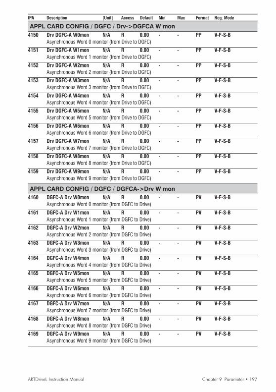
ARTDriveL Instruction Manual Chapter 9 Parameter • 197
IPA Description [Unit] Access Default Min Max Format Reg. Mode
APPL CARD CONFIG / DGFC / Drv->DGFCA W mon4150 Drv DGFC-A W0mon N/A R 0.00 - - PP V-F-S-B
Asynchronous Word 0 monitor (from Drive to DGFC)
4151 Drv DGFC-A W1mon N/A R 0.00 - - PP V-F-S-BAsynchronous Word 1 monitor (from Drive to DGFC)
4152 Drv DGFC-A W2mon N/A R 0.00 - - PP V-F-S-BAsynchronous Word 2 monitor (from Drive to DGFC)
4153 Drv DGFC-A W3mon N/A R 0.00 - - PP V-F-S-BAsynchronous Word 3 monitor (from Drive to DGFC)
4154 Drv DGFC-A W4mon N/A R 0.00 - - PP V-F-S-BAsynchronous Word 4 monitor (from Drive to DGFC)
4155 Drv DGFC-A W5mon N/A R 0.00 - - PP V-F-S-BAsynchronous Word 5 monitor (from Drive to DGFC)
4156 Drv DGFC-A W6mon N/A R 0.00 - - PP V-F-S-BAsynchronous Word 6 monitor (from Drive to DGFC)
4157 Drv DGFC-A W7mon N/A R 0.00 - - PP V-F-S-BAsynchronous Word 7 monitor (from Drive to DGFC)
4158 Drv DGFC-A W8mon N/A R 0.00 - - PP V-F-S-BAsynchronous Word 8 monitor (from Drive to DGFC)
4159 Drv DGFC-A W9mon N/A R 0.00 - - PP V-F-S-BAsynchronous Word 9 monitor (from Drive to DGFC)
APPL CARD CONFIG / DGFC / DGFCA->Drv W mon4160 DGFC-A Drv W0mon N/A R 0.00 - - PV V-F-S-B
Asynchronous Word 0 monitor (from DGFC to Drive)
4161 DGFC-A Drv W1mon N/A R 0.00 - - PV V-F-S-BAsynchronous Word 1 monitor (from DGFC to Drive)
4162 DGFC-A Drv W2mon N/A R 0.00 - - PV V-F-S-BAsynchronous Word 2 monitor (from DGFC to Drive)
4163 DGFC-A Drv W3mon N/A R 0.00 - - PV V-F-S-BAsynchronous Word 3 monitor (from DGFC to Drive)
4164 DGFC-A Drv W4mon N/A R 0.00 - - PV V-F-S-BAsynchronous Word 4 monitor (from DGFC to Drive)
4165 DGFC-A Drv W5mon N/A R 0.00 - - PV V-F-S-BAsynchronous Word 5 monitor (from DGFC to Drive)
4166 DGFC-A Drv W6mon N/A R 0.00 - - PV V-F-S-BAsynchronous Word 6 monitor (from DGFC to Drive)
4167 DGFC-A Drv W7mon N/A R 0.00 - - PV V-F-S-BAsynchronous Word 7 monitor (from DGFC to Drive)
4168 DGFC-A Drv W8mon N/A R 0.00 - - PV V-F-S-BAsynchronous Word 8 monitor (from DGFC to Drive)
4169 DGFC-A Drv W9mon N/A R 0.00 - - PV V-F-S-BAsynchronous Word 9 monitor (from DGFC to Drive)

198 • Chapter 9 Parameter ARTDriveL Instruction Manual
IPA Description [Unit] Access Default Min Max Format Reg. Mode
SAVE PARAMETERSAVyL drive allows two different commands to save the parameters modified in the regulation mode selected:• by STARTUP menu, “Save Config?” command• by all other menus, “SAVE PARAMETERS” commandAny changes made in STARTUP menu require “Save Config?” command, which saves all entire regulation mode selected.It is recommended every time the user made any changes into STARTUP menu.“SAVE PARAMETERS” command saves all the changes made out of STARTUP menu only.When on the keypad display appears blinking message “Use Save Config”, use “Save Config?” command

ARTDriveL Instruction Manual Chapter 9 Parameter • 199
IPA Description [Unit] Access Default Min Max Format Reg. Mode
CUSTOM FUNCTIONSCUSTOM FUNCTIONSCUSTOM FUNCTIONSCUSTOM FUNCTIONSCUSTOM FUNCTIONSThe access to CUSTOM FUNCTIONS menu is allowed by Level 1 password: 12345. It must to be set in theSERVICE menu.COMPARE: The Block supplies two signal Comparators, Compare 1 and Compare 2, with the same features.Each Comparator is in a position to compare two or three input signals (INP0, INP1, INP2).Some comparisons allow to set via Cmp x window a window, in count, stating an acceptable range among the signals.Example:-INP0 and INP1 have to be compared as “INP0 = INP1”
INP0 = +1000countINP1 = +1000countWindow = 100count
In this case the equality is true for a maximum overall variation of INP1 between 1100 and 900 counts.Possible variations:
None noneI0 = = I1 INP0-window ≤ INP1 ≤ INP0+windowI0 != I1 INP1 lower INP0-window or INP1 higher INP0+windowI0 < I1 INP0 lower INP1I0 > I1 INP0 higher INP1I0 < I1 > I2 INP0<INP1<INP2 (INP1 included between..)|I0| == |I1| INP0| -window ≤ |INP1| ≤ |INP0| +window|I0| != |I1| INP1| lower |INP0| -window,or |INP1| higher |INP0| +window|I0| < |I1| INP0| lower |INP1||I0| > |I1| INP0| higher |INP1||I0| < |I1| < |I2| INP0| <|INP1| <|INP2| (|INP1|I0 AND I1 AND I2 AND logic between I0, I1 and I2I0 OR I1 OR I2 OR logic between I0, I1 and I2I0 XOR I1 XOR logic between I0 and I1
CUSTOM FUNCTIONS / Compare / Compare 1
CUSTOM FUNCTIONS / Compare / Compare 1 / Compare 1 src6049 Cmp 1 inp 0 src N/A RWS IPA 6041 List 5 PIN V-F-S-B
IPA 6041 Cmp 1 inp 0 = DefaultIt allows to select the origin of the input signal 0 to be compared of the Compare 1 block(refer to signals List 5 of Pick List manual)
6050 Cmp 1 inp 1 src N/A RWS IPA 6042 List 5 PIN V-F-S-BIPA 6042 Cmp 1 inp 1 = DefaultIt allows to select the origin of the input signal 1 to be compared of the Compare 1 block(refer to signals List 5 of Pick List manual)
6051 Cmp 1 inp 2 src N/A RWS IPA 6043 List 5 PIN V-F-S-BIPA 6043 Cmp 1 inp 2 = DefaultIt allows to select the origin of the input signal 2 to be compared of the Compare 1 block(refer to signals List 5 of Pick List manual)
CUSTOM FUNCTIONS / Compare / Compare 1 / Compare 1 cfg6041 Cmp 1 inp 0 N/A RWS 0.00 - - PV V-F-S-B
Value of the internal input signal 0, default connected to Cmp 1 inp 0 src
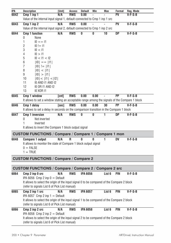
200 • Chapter 9 Parameter ARTDriveL Instruction Manual
IPA Description [Unit] Access Default Min Max Format Reg. Mode6042 Cmp 1 inp 1 N/A RWS 0.00 - - PV V-F-S-B
Value of the internal input signal 1, default connected to Cmp 1 inp 1 src
6043 Cmp 1 inp 2 N/A RWS 0.00 - - PV V-F-S-BValue of the internal input signal 2, default connected to Cmp 1 inp 2 src
6044 Cmp 1 function N/A RWS 0 0 10 DP V-F-S-B0 None1 I0 == I12 I0 != I13 I0 < I14 I0 > I15 I0 < I1 < I26 |I0| == |I1|7 |I0| != |I1|8 |I0| < |I1|9 |I0| > |I1|10 |I0|< |I1| <|I2|11 I0 AND I1 AND I212 I0 OR I1 AND I213 I0 XOR I1
6045 Cmp 1 window [cnt] RWS 0.00 0.00 - PP V-F-S-BIt allows to set a window stating an acceptable range among the signals of the Compare 1 block
6046 Cmp 1 delay [sec] RWS 0.00 0.00 30 PP V-F-S-BIt allows to set a delay in seconds on the comparison transition in the Compare 1 block
6047 Cmp 1 inversion N/A RWS 0 0 1 DP V-F-S-B0 Not inverted1 InvertedIt allows to invert the Compare 1 block output signal
CUSTOM FUNCTIONS / Compare / Compare 1 / Compare 1 mon6048 Compare 1 output N/A R 0 0 1 DV V-F-S-B
It allows to monitor the state of Compare 1 block output signal0 = FALSE1 = TRUE
CUSTOM FUNCTIONS / Compare / Compare 2
CUSTOM FUNCTIONS / Compare / Compare 2 / Compare 2 src6064 Cmp 2 inp 0 src N/A RWS IPA 6056 List 6 PIN V-F-S-B
IPA 6056 Cmp 2 inp 0 = DefaultIt allows to select the origin of the input signal 0 to be compared of the Compare 2 block(refer to signals List 6 of Pick List manual)
6065 Cmp 2 inp 1 src N/A RWS IPA 6057 List 6 PIN V-F-S-BIPA 6057 Cmp 2 inp 1 = DefaultIt allows to select the origin of the input signal 1 to be compared of the Compare 2 block(refer to signals List 6 of Pick List manual)
6066 Cmp 2 inp 2 src N/A RWS IPA 6058 List 6 PIN V-F-S-BIPA 6058 Cmp 2 inp 2 = DefaultIt allows to select the origin of the input signal 2 to be compared of the Compare 2 block(refer to signals List 6 of Pick List manual)
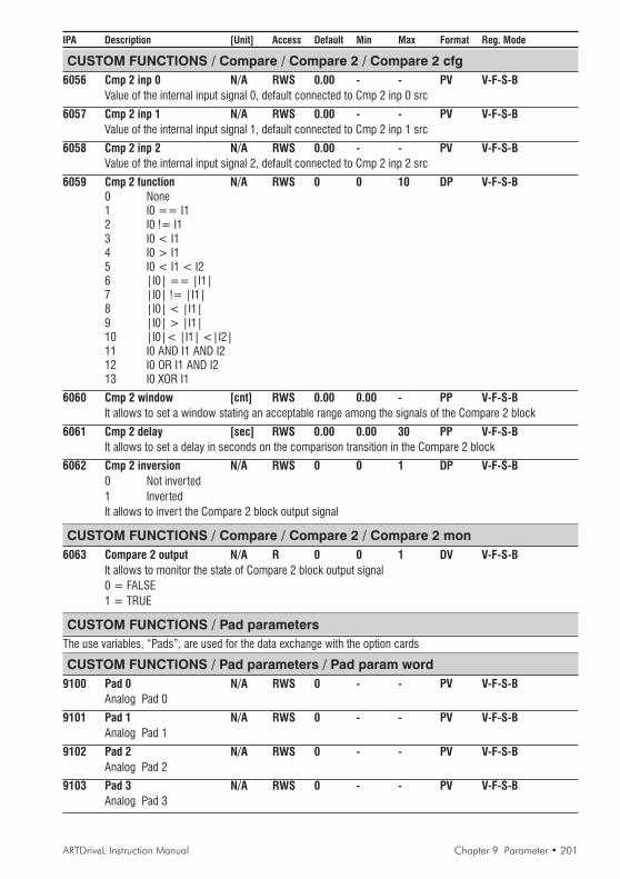
ARTDriveL Instruction Manual Chapter 9 Parameter • 201
IPA Description [Unit] Access Default Min Max Format Reg. Mode
CUSTOM FUNCTIONS / Compare / Compare 2 / Compare 2 cfg6056 Cmp 2 inp 0 N/A RWS 0.00 - - PV V-F-S-B
Value of the internal input signal 0, default connected to Cmp 2 inp 0 src
6057 Cmp 2 inp 1 N/A RWS 0.00 - - PV V-F-S-BValue of the internal input signal 1, default connected to Cmp 2 inp 1 src
6058 Cmp 2 inp 2 N/A RWS 0.00 - - PV V-F-S-BValue of the internal input signal 2, default connected to Cmp 2 inp 2 src
6059 Cmp 2 function N/A RWS 0 0 10 DP V-F-S-B0 None1 I0 == I12 I0 != I13 I0 < I14 I0 > I15 I0 < I1 < I26 |I0| == |I1|7 |I0| != |I1|8 |I0| < |I1|9 |I0| > |I1|10 |I0|< |I1| <|I2|11 I0 AND I1 AND I212 I0 OR I1 AND I213 I0 XOR I1
6060 Cmp 2 window [cnt] RWS 0.00 0.00 - PP V-F-S-BIt allows to set a window stating an acceptable range among the signals of the Compare 2 block
6061 Cmp 2 delay [sec] RWS 0.00 0.00 30 PP V-F-S-BIt allows to set a delay in seconds on the comparison transition in the Compare 2 block
6062 Cmp 2 inversion N/A RWS 0 0 1 DP V-F-S-B0 Not inverted1 InvertedIt allows to invert the Compare 2 block output signal
CUSTOM FUNCTIONS / Compare / Compare 2 / Compare 2 mon6063 Compare 2 output N/A R 0 0 1 DV V-F-S-B
It allows to monitor the state of Compare 2 block output signal0 = FALSE1 = TRUE
CUSTOM FUNCTIONS / Pad parametersThe use variables, “Pads”, are used for the data exchange with the option cards
CUSTOM FUNCTIONS / Pad parameters / Pad param word9100 Pad 0 N/A RWS 0 - - PV V-F-S-B
Analog Pad 0
9101 Pad 1 N/A RWS 0 - - PV V-F-S-BAnalog Pad 1
9102 Pad 2 N/A RWS 0 - - PV V-F-S-BAnalog Pad 2
9103 Pad 3 N/A RWS 0 - - PV V-F-S-BAnalog Pad 3

202 • Chapter 9 Parameter ARTDriveL Instruction Manual
IPA Description [Unit] Access Default Min Max Format Reg. Mode
9104 Pad 4 N/A RWS 0 - - PV V-F-S-BAnalog Pad 4
9105 Pad 5 N/A RWS 0 - - PV V-F-S-BAnalog Pad 5
9106 Pad 6 N/A RWS 0 - - PV V-F-S-BAnalog Pad 6
9107 Pad 7 N/A RWS 0 - - PV V-F-S-BAnalog Pad 7
9108 Pad 8 N/A RWS 0 - - PV V-F-S-BAnalog Pad 8
9109 Pad 9 N/A RWS 0 - - PV V-F-S-BAnalog Pad 9
9110 Pad 10 N/A RWS 0 - - PV V-F-S-BAnalog Pad 10
9111 Pad 11 N/A RWS 0 - - PV V-F-S-BAnalog Pad 11
9112 Pad 12 N/A RWS 0 - - PV V-F-S-BAnalog Pad 12
9113 Pad 13 N/A RWS 0 - - PV V-F-S-BAnalog Pad 13
9114 Pad 14 N/A RWS 0 - - PV V-F-S-BAnalog Pad 14
9115 Pad 15 N/A RWS 0 - - PV V-F-S-BAnalog Pad 15
CUSTOM FUNCTIONS / Pad parameters / Pad param bit9116 Dig pad 0 N/A RWS 0 0 1 DV V-F-S-B
Digital Pad 1
9117 Dig pad 1 N/A RWS 0 0 1 DV V-F-S-BDigital Pad 2
9118 Dig pad 2 N/A RWS 0 0 1 DV V-F-S-BDigital Pad 3
9119 Dig pad 3 N/A RWS 0 0 1 DV V-F-S-BDigital Pad 3
9120 Dig pad 4 N/A RWS 0 0 1 DV V-F-S-BDigital Pad 4
9121 Dig pad 5 N/A RWS 0 0 1 DV V-F-S-BDigital Pad 5
9122 Dig pad 6 N/A RWS 0 0 1 DV V-F-S-BDigital Pad 6
9123 Dig pad 7 N/A RWS 0 0 1 DV V-F-S-BDigital Pad 7
9124 Dig pad 8 N/A RWS 0 0 1 DV V-F-S-BDigital Pad 8
9125 Dig pad 9 N/A RWS 0 0 1 DV V-F-S-BDigital Pad 9

ARTDriveL Instruction Manual Chapter 9 Parameter • 203
IPA Description [Unit] Access Default Min Max Format Reg. Mode
9126 Dig pad 10 N/A RWS 0 0 1 DV V-F-S-BDigital Pad 10
9127 Dig pad 11 N/A RWS 0 0 1 DV V-F-S-BDigital Pad 11
9128 Dig pad 12 N/A RWS 0 0 1 DV V-F-S-BDigital Pad 12
9129 Dig pad 13 N/A RWS 0 0 1 DV V-F-S-BDigital Pad 13
9130 Dig pad 14 N/A RWS 0 0 1 DV V-F-S-BDigital Pad 14
9131 Dig pad 15 N/A RWS 0 0 1 DV V-F-S-BDigital Pad 15
CUSTOM FUNCTIONS / ConnectThis block function connects signals to programmable block area, using drive parameters that areaccessible through the “Conf99” PC program or drive keypad menu.Connect A, connects up to 7 analog input signalsConnect B, connects up to 7 digital signals inputs
CUSTOM FUNCTIONS / Connect/ Connect A6070 ConnectA inp 0 src N/A RWS IPA 4000 List 2 PIN V-F-S-B
IPA 4000 NULL = Default
6071 ConnectA inp 1 src N/A RWS IPA 4000 List 2 PIN V-F-S-BIPA 4000 NULL = Default
6072 ConnectA inp 2 src N/A RWS IPA 4000 List 2 PIN V-F-S-BIPA 4000 NULL = Default
6073 ConnectA inp 3 src N/A RWS IPA 4000 List 2 PIN V-F-S-BIPA 4000 NULL = Default
6074 ConnectA inp 4 src N/A RWS IPA 4000 List 2 PIN V-F-S-BIPA 4000 NULL = Default
6075 ConnectA inp 5 src N/A RWS IPA 4000 List 2 PIN V-F-S-BIPA 4000 NULL = Default
6076 ConnectA inp 6 src N/A RWS IPA 4000 List 2 PIN V-F-S-BIPA 4000 NULL = Default
6077 ConnectA inp 7 src N/A RWS IPA 4000 List 2 PIN V-F-S-BIPA 4000 NULL = Default
CUSTOM FUNCTIONS / Connect/ Connect B6078 ConnectB inp 0 src N/A RWS IPA 4000 List 1 PIN V-F-S-B
IPA 4000 NULL = Default
6079 ConnectB inp 1 src N/A RWS IPA 4000 List 1 PIN V-F-S-BIPA 4000 NULL = Default
6080 ConnectB inp 2 src N/A RWS IPA 4000 List 1 PIN V-F-S-BIPA 4000 NULL = Default
6081 ConnectB inp 3 src N/A RWS IPA 4000 List 1 PIN V-F-S-BIPA 4000 NULL = Default

204 • Chapter 9 Parameter ARTDriveL Instruction Manual
IPA Description [Unit] Access Default Min Max Format Reg. Mode
6082 ConnectB inp 4 src N/A RWS IPA 4000 List 1 PIN V-F-S-BIPA 4000 NULL = Default
6083 ConnectB inp 5 src N/A RWS IPA 4000 List 1 PIN V-F-S-BIPA 4000 NULL = Default
6084 ConnectB inp 6 src N/A RWS IPA 4000 List 1 PIN V-F-S-BIPA 4000 NULL = Default
6085 ConnectB inp 7 src N/A RWS IPA 4000 List 1 PIN V-F-S-BIPA 4000 NULL = Default
SAVE PARAMETERSAVyL drive allows two different commands to save the parameters modified in the regulation mode selected:• by STARTUP menu, “Save Config?” command• by all other menus, “SAVE PARAMETERS” commandAny changes made in STARTUP menu require “Save Config?” command, which saves all entire regulation mode selected.It is recommended every time the user made any changes into STARTUP menu.“SAVE PARAMETERS” command saves all the changes made out of STARTUP menu only.When on the keypad display appears blinking message “Use Save Config”, use “Save Config?” command

ARTDriveL Instruction Manual Chapter 9 Parameter • 205
IPA Description [Unit] Access Default Min Max Format Reg. Mode
SERVICESERVICESERVICESERVICESERVICESERVICE menu allows the setting of the password to enable Level 1 drive menus: 12345.To have the access of Level 1 drive menus, edit 12345 password into “Insert Password” parameter and confirm itusing “Enter” button.NOTE! Level 1 password must be edit every recycle drive supplySERVICE menu allows also the setting of the password to enable Level 2 drive menu: ask Level 2 password to thetechnical support.To have the access of Level 2 drive menus:
1_ edit 12345 password into “Insert Password” parameter and confirm it using “Enter” button2_ check the password through “Check password” parameter using “Enter” button
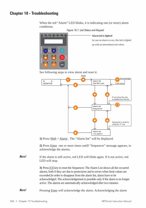
206 • Chapter 10 Troubleshooting ARTDriveL Instruction Manual
Chapter 10 - Troubleshooting
When the red “Alarm” LED blinks, it is indicating one (or more) alarmconditions.
Figure 10.1: Led Status and Keypad
See following steps to view alarm and reset it:
R: S:
MONITOR
Alarm
Alarm list
Spd fbk Loss
Alarm list
Sequencer
Alarm list
<no alarm>
Acknowledged
If still active
If not active the enty
is deleted from the list
Sequencer is reset by
using the “0” key
1) Press Shift + Alarm . The “Alarm list” will be displayed.
2) Press Enter one or more times untill “Sequencer” message appears, toacknowledge the alarms.
NOTE! If the alarm is still active, red LED will blink again. If it not active, redLED will stop.
3) Press [O] key to reset the Sequencer. The Alarm List shows all the occurredalarms, both if they are due to protections and to errors when limit values areexceeded.In order to disappear from the alarm list, alarm have to beacknowledged. The acknowledgement is possible only if the alarm is no longeractive. The alarms are automatically acknowledged after two minutes.
NOTE! Pressing Enter will acknowledge the alarm. Acknowledging the alarm
Alarm led is lighted
In case an alarm occurs, this led is lighed
up with an intermittent red colour.

ARTDriveL Instruction Manual Chapter 10 Troubleshooting • 207
will only remove it from the active alarm list. If the alarm condition alsoresulted in a drive trip, the sequence will also need to be reset. This canbe done by pressing the [O] key. The drive cannot be re-enabled orstarted after a trip condition unless the drive sequencer is reset.The drive State Machine, controls the drive running and starting,accounting for protection & alarming, command sequence, and resetstatus.The table below displays various operation states by Sequencer statusnumber:
Sequencer status State
1 Magnetization running
2 Magnetization completed, Stop
3 Start
4 Fast stop, Stop
5 Fast stop, Start
9 No alarm, drive is ready to accept all commands
10 Magnetization running and Start command already present
12 Alarm active
16 Alarm not active, waiting for reset
TAV3i020
To read the sequencer status of the State Machine, go to menu:
⎡ ⎤R: S:MONITOR⎣ ⎦
⎡ ⎤Output voltage0 V⎣ ⎦
3 times to
⎡ ⎤MONITORAdvanced status⎣ ⎦
⎡ ⎤DC link voltage580 V⎣ ⎦
3 times to
⎡ ⎤Sequencer status12⎣ ⎦
10.1 List of Regulation Alarm Events
Table 10.1.1 provides a description of regulation alarm events andinformation on how to configure the intended drive behaviour on theiroccurrence (where applicable).

208 • Chapter 10 Troubleshooting ARTDriveL Instruction Manual
Table 10.1.1 Regulation Alarm Events
Failure supply Disable drive No No NA 21 1One or more of the power supply circuits in the control section failed
Undervoltage Disable drive No Yes Yes 22 2Logic is based on the number of attempts
Voltage on the drive DC link is lower than the minimum threshold for the given Mains voltage setting.
Overvoltage Disable drive No Yes Yes 23 3Voltage on the drive DC link is higher than the maximum threshold for the given Mains voltage setting
IGBT desat flt Disable drive No Yes Yes 24 4No more than 2 attempts in 30 seconds
IGBT instantaneous overcurrent was detected by gate desaturation sensing circuit
Inst Overcurrent Disable drive No Yes Yes 25 5No more than 2 attempts /30sec.
IGBT instantaneous overcurrent was detected by output current sensor
Ground fault Programmable No No Yes 26 6Output phase discharge to ground
Curr fbk loss Disable drive No No No 27 7A failure of current sensor feeedback or power supply was detected
External fault Programmable Programmable Yes Programm. 28 8External fault input is active
Spd fbk loss Programmable No No No 29 9A failure of the speed feedback sensor or power supply was detected
Module OT Disable drive Constant, 10 msec No No 30 10IGBT overtemperature was detected by internal sensor (models 0.75 to 20 Hp only)
Heatsink OT Disable drive Constant, 1000 msec No No 31 11Heatsink overtemperature was detected by thermal contact (only for models 18.5 kW and over)
Motor OT Programmable Programmable Yes Programm. 32 12Motor overtemperature was detected by thermal contact or PTC thermistor
Heatsink S OT Programmable Programmable Yes Programm. 33 13Heatsink linear temperature sensor threshold was exceeded
Regulat S OT Programmable Programmable Yes Programm. 34 14Regulation board linear temperature sensor threshold was exceeded
Intake Air S OT Programmable Programmable Yes Programm. 35 15Cooling air intake linear temperature sensor threshold was exceeded (only for models 18.5 kW and over)
Cont fbk fail Programmable No Yes No 36 16It trips when the contact feedback signal is not detected
Comm card fault Programmable No Yes Programm. 37 17Fault of optional LAN communication board
Appl card fault Disable drive No No No 38 18Fault of optional application coprocessor board
Drv overload Programmable No No No 39 19Drive overload accumulator exceeded trip threshold
Ala
rm n
ame
Des
crip
tion
Driv
e ac
tivity
afte
r ala
rm
Hol
d of
f
Res
tart
Res
tart
tim
e
Cod
e in
theA
larm
list
Bit
posi
tion
inA
larm
list

ARTDriveL Instruction Manual Chapter 10 Troubleshooting • 209
Mot overload Programmable No No No 40 20Motor overload accumulator exceeded trip threshold
BU overload Programmable No No No 41 21Braking resistor overload accumulator exceeded trip threshold
Data lost Disable drive No No No 42 22Data corrupted in non-volatile memory
Brake fbk fail Programmable No No No 43 23It trips when the brake feedback signal is not detected
Max time Disable drive No No No 44 24Software task time overrun was detected
Sequencer Disable drive No No No 45 25Alarm event caused drive disable
Door fbk fail Disable drive Yes No No 46 26It trips when the door feedback signal is not detected
Overspeed No Yes No No 47 27Maximum speed threshold was exceeded while drive in RUN state
UV repetitive Disable drive No No No 48 28If n. of faults is set to max the Alarm is disabled.
More than a programmable number of UV fault were detected in 5 minutes
IOC repetitive Disable drive No No No 49 29More than 2 OC faults were detected in 30 sec.
IGBTdesat repet Disable drive No No No 50 30More than 2 IGBT desat faults were detected in 30 sec.
WatchDog user Disable drive No No No 51 31The drive failed to retrigger the communication watchdog within the specified time
Hw fail Disable drive No No No 52 32Communication failure between Drive Regulation board and one of its options or I/O expansions.
Ala
rm n
ame
Des
crip
tion
Driv
e ac
tivity
afte
r ala
rm
Hol
d of
f
Res
tart
Res
tart
tim
e
Cod
e in
theA
larm
list
Bit
posi
tion
inA
larm
list

210 • Chapter 10 Troubleshooting ARTDriveL Instruction Manual
10.2 List of Configuration and DataBase Error Alarm Events
Entering bad data or conflicting data into the drive configuration willcause user errors to be displayed.These type of errors can be:- Configuration errors- Database errors (DB errors)Refer to the following paragraphs for descriptions.
Drive size setting
NOTE! If the User changes the Drive size, the drive will display: Drv size: newsize - old size. For example: Drive size: 0 - 1
10.2.1 Configuration Errors
Configuration errors can occur by entering incompatible or invalidparameter data.The drive reports configuration error by the following example description:
Calc error: Calc error numberParam: Param error number
The Calc error number denotes the cause of invalid calculation. The Calcerror number is composed as follows:Calc error number = Offset + Error code
The Offset denotes the type of error:0 for specific errors100 for errors originated by the database calculation
(see DB error paragraph)500 for errors due to floating point calculation
(exception, divide by zero etc..)600 for errors originated by the configuration calculations
(range and so on).
The Error code denotes the origin cause of the error, see values listbelow.
Error code values lists
Error code values for Offset 0 :0 no error1 signal not managed in current configurator state2 cannot stop regulation3 recipe export error4 recipe import error5 error while loading selftune data6 error while loading motor data7 reserved

ARTDriveL Instruction Manual Chapter 10 Troubleshooting • 211
8 error while loading customer specific data9 error while loading drive size data10 error while writing file size.ini11 error while apply database. The operation is refused because
errors arised during group calculation.To reset the errors it isnecessary re-enter the data, and confirm correctness
12 error while saving too changes
Error code values for Offset 100: See DB errors, section 10.2.3
Error code values for Offset 500 (500 + error code):
3 Integer overflow4 Floating overflow5 Floating underflow7 Divide by zero9 Undefined float10 Conversion error11 Floating point stack underflow12 Floating point stack overflow
Error code values for Offset 600 (600 + error code):
0 no error1 switching freq. error2 mains voltage error3 ambient temperature error4 regulation mode error5 take selection error6 base speed error7 drive size error
For example, Calc error number 606 is a configuration error (600)caused by speed base value (6) out of range.The Param error number is not meaningful.
10.2.2 Database Errors (DB Errors)
DB errors are caused by a incorrect setting in a single parameter. Thisproblem is originated in the database calculation. For example the mostcommon are:- DB error Limit HIGH- DB error Limit LOWThe message DB error is displayed by the drive in this format:DB ERR IPA: error code
The IPA denotes the parameter number which caused the DB errorcalculation. The error code denotes the type error.Example of message DB error displayed: DB ERR 3420: 5This means that the DB error is caused by IPA 3420 (V/f voltage) whichis below the low limit; Error code 5 denotes the type error (for the DBerror code values list see below). To find the low limit, which dependson drive configuration, it is possible to go to the V/f voltage parameter
Note !See chapter 12Parameter index

212 • Chapter 10 Troubleshooting ARTDriveL Instruction Manual
on the keypad. Press the Shift key and then the Help key, the followingwill be displayed:
Max ValueMin ValueDef(ault) ValueUnitRaw valueIPADescription(Access) mode
In most cases it is enough to set a new value which is within the limits.
DB error code list
0 No error1 SBI PROBLEM 0x012 Generic error3 Attribute not exist4 Limit High5 Limit Low11 Division by zero12 Int Overflow13 Int Underflow14 Long Overflow15 Long Underflow16 Domain Error17 Indirection Error18 Reached wrong eof19 Dbase not configured20 Value not valid21 Process doesn’t reply22 Wrong record size23 Attribute read only24 SBI PROBLEM 0x1825 Command not yet implemented26 Command wrong27 Read file error28 Header wrong29 Reserved for internal use30 Parameter not exist31 Parameter read only32 Parameter ”z” only48 SBI PROBLEM 0x30
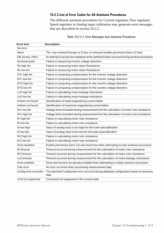
ARTDriveL Instruction Manual Chapter 10 Troubleshooting • 213
10.2.3 List of Error Codes for All Autotune Procedures
The different autotune procedures for Current regulator, Flux regulator,Speed regulator or Analog input calibration may generate error messagesthat are described in section 10.2.2 .
Table 10.2.3.1: Error Messages from Autotune Procedures
Error text DescriptionNo errorAbort The user entered Escape or O key, or removed enable permissive (term 12 low)DB access <IPA> An attempt to access the database at the speficied index occurred during autotune procedureNo break point Failure in measuring inverter voltage distortionRs high lim Failure in measuring motor stator ResistanceRs low lim Failure in measuring motor stator ResistanceDTL high lim Failure in computing compensation for the inverter voltage distortionDTL low lim Failure in computing compensation for the inverter voltage distortionDTS high lim Failure in computing compensation for the inverter voltage distortionDTS low lim Failure in computing compensation for the inverter voltage distortionLsS high lim Failure in calculating motor leakage inductanceLsS low lim Failure in calculating motor leakage inductanceImNom not found Identification of rated magnetizing current failedImNom not found Identification of maximum magnetizing current failedRrV low lim Voltage limit exceeded during measurement for the calculation of motor rotor resistanceRrV high lim Voltage limit exceeded during measurement for the calculation of motor rotor resistanceRr high lim Failure in calculating motor rotor resistanceRr low lim Failure in calculating motor rotor resistanceAI too high Value of analog input is too high for full scale autocalibrationAI too low Value of analog input is too low for full scale autocalibrationRr2 high lim Failure in calculating motor rotor resistanceRr2 low lim Failure in calculating motor rotor resistanceDrive disabled Enable permissive (term 12) was found low when attempting to start autotune procedureRr timeout Timeout occurred during measurement for the calculation of motor rotor resistanceRr2 timeout Timeout occurred during measurement for the calculation of motor rotor resistanceLsS timeout Timeout occurred during measurement for the calculation of motor leakage inductanceDrive enabled Drive was found to be already enabled when attempting to initiate autotune procedureCalc error An error occurred when processing measurement dataConfig error<errcode> The specified Configurator error occurred during database configuration based on autotune
dataCmd not supported Command not supported in the current state

214 • Chapter 11 EMC Directive - Declaration of Conformity ARTDriveL Instruction Manual
Chapter 11 - EMC Directive - Declaration of Conformity
EMC DirectiveThe possible Validity Fields of the EMC Directive (89/336) applied to PDS “CEmarking” summarises the presumption of compliance with the Essential Requirements of theEMC Directive, which is formulated in the EC Declaration of Conformity Clauses numbers [.]refer to European Commission document “Guide to the Application of Directive 89/336/EEC”1997 edition. ISBN 92-828-0762-2
Validity Field
-1-Finished Product/ Complex
componentavailable to general public
[Clauses: 3.7, 6.2.1, 6.2.3.1 &6.3.1]
A PDS (or CDM/BDM) of theUnrestricted Distribution class
-2-Finished Product/Complex
componentonly for professional assemblers
[Clauses: 3.7, 6.2.1, 6.2.3.2 &6.3.2]
A PDS (or CDM/BDM)of the Restricted Distribution class
sold to be included as part of asystem or installation
-3-Installation
[Clause: 6.5]Several combined items of system,
finished product or othercomponents brought together at a
given place. May include PDSs(CDM or BDM), possibly of differentclasses -Restricted or Unrestricted
-4-System
[Clause: 6.4]
Ready to use finished item(s). Mayinclude PDSs (CDM or BDM),possibly of different classes- Restricted or Unrestricted
Description
Placed on the market as a single commercial unit for distribution and final use.Free movement based on compliance with the EMC Directive- EC Declaration of conformity required - CE marking required- PDS or CDM/BDM should comply with IEC 1800-3/EN 61800-3The manufacturer of the PDS (or CDM/BDM) is responsible for the EMC behaviour of the PDS (or CDM/BDM), under specified conditions. EMC measures outside the item are described in an easy to understandfashion and could actually be implemented by a layman in the field of EMC.The EMC responsibility of the assembler of the final product is to follow the manufacturer’s recommenda-tions and guidelines.Note: The manufacturer of the PDS (or CDM/BDM) is not responsible for the resulting behaviour of anysystem or installation which includes the PDS, see Validity Fields 3 or 4.
Not placed on the marked as a single commercial unit for distribution and final use.Intended only for professional assemblers who have a level of technical competence to correctly install.- No EC Declaration of conformity - No CE marking- PDS or CDM/BDM should comply with IEC 1800-3/EN 61800-3The manufacturer of the PDS (or CDM/BDM) is responsible for the provision of installation guidelines thatwill assist the manufacturer of the apparatus, system or installation to achieve compliance.The resulting EMC behaviour is the responsibility of the manufacturer of the apparatus, system, or installa-tion, for which its own standards may apply.
Not intended to be placed on the market as a single functional unit (no free movement).Each system included is subject to the provisions of the EMC Directive.- No EC Declaration of conformity - No CE marking- For the PDSs or CDM/BDMs themselves see Validity Fields 1 or 2- Responsibility of the manufacturer of the PDS may include commissioningThe resulting EMC behaviour is the responsibility of the manufacturer of the installation in co-operation withthe user (e.g. by following an appropriate EMC plan). Essential protection requirements of EMC Directiveapply regarding the neighbourhood of the installation.
Has a direct function for the final user. Placed on the market for distribution as a single functional unit, or asunits intended to be easily connected together.- EC Declaration of conformity required - CE marking required for the system- For the PDSs or CDM/BDMs themselves see Validity Fields 1 or 2The resulting EMC behaviour, under specified conditions is the responsibility of the manufacturer of thesystem by using a modular or system approach as appropriate.Note: The manufacturer of the system is not responsible for the resulting behaviour of any installationwhich includes the PDS, see Validity Field 3.
Examples of application in the different Validity Fields:
1 BDM to be used anywhere: (example in domestic premises, or BDM available from commercial distributors), sold without any knowledge of thepurchaser or the application. The manufacture is responsible that sufficient EMC can be achieved even by any unknown customer or layman (snap-in, switch-on).
2 CDM/BDM or PDS for general purpose: to be incorporated in a machine or for industrial application This is sold as a subassembly to a professionalassembler who incorporates it in a machine, system or installation. Conditions of use are specified in the manufacturer’s documentation. Exchangeof technical data allows optimization of the EMC solution.. (See restricted distribution definition).
3 Installation: It can consist of different commercial units (PDS, mechanics, process control etc.). The conditions of incorporation for the PDS (CDMor BDM) are specified at the time of the order, consequently an exchange of technical data between supplier and client is possible. The combinationof the various items in the installation should be considered in order to ensure EMC. Harmonic compensation is an evident example of this, for bothtechnical and economical reasons. (E.g. rolling mill, paper machine, crane, etc.)
4 System: Ready to use finished item which includes one or more PDSs (or CDMs/BDMs); e.g. household equipment, air conditioners, standardmachine tools, standard pumping systems, etc.
Rela
tes
to P
DS o
r CD
M o
r BD
M d
irect
lyRe
late
s to
app
licat
ion
of P
DS o
r CDM
or B
DM

ARTDriveL Instruction Manual Chapter 11 EMC Directive - Declaration of Conformity • 215
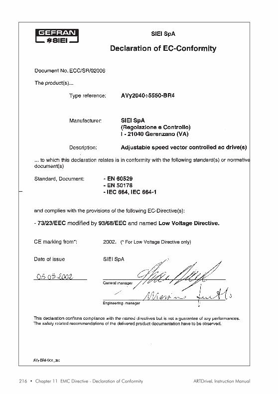
216 • Chapter 11 EMC Directive - Declaration of Conformity ARTDriveL Instruction Manual
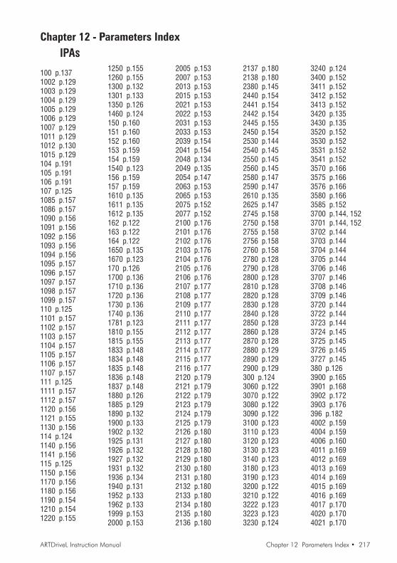
ARTDriveL Instruction Manual Chapter 12 Parameters Index • 217
IPAs
100 p.1371002 p.1291003 p.1291004 p.1291005 p.1291006 p.1291007 p.1291011 p.1291012 p.1301015 p.129104 p.191105 p.191106 p.191107 p.1251085 p.1571086 p.1571090 p.1561091 p.1561092 p.1561093 p.1561094 p.1561095 p.1571096 p.1571097 p.1571098 p.1571099 p.157110 p.1251101 p.1571102 p.1571103 p.1571104 p.1571105 p.1571106 p.1571107 p.157111 p.1251111 p.1571112 p.1571120 p.1561121 p.1551130 p.156114 p.1241140 p.1561141 p.156115 p.1251150 p.1561170 p.1561180 p.1561190 p.1541210 p.1541220 p.155
1250 p.1551260 p.1551300 p.1321301 p.1331350 p.1261460 p.124150 p.160151 p.160152 p.160153 p.159154 p.1591540 p.123156 p.159157 p.1591610 p.1351611 p.1351612 p.135162 p.122163 p.122164 p.1221650 p.1351670 p.123170 p.1261700 p.1361710 p.1361720 p.1361730 p.1361740 p.1361781 p.1231810 p.1551815 p.1551833 p.1481834 p.1481835 p.1481836 p.1481837 p.1481880 p.1261885 p.1291890 p.1321900 p.1331902 p.1321925 p.1311926 p.1321927 p.1321931 p.1321936 p.1341940 p.1311952 p.1331962 p.1331999 p.1532000 p.153
2005 p.1532007 p.1532013 p.1532015 p.1532021 p.1532022 p.1532031 p.1532033 p.1532039 p.1542041 p.1542048 p.1342049 p.1352054 p.1472063 p.1532065 p.1532075 p.1522077 p.1522100 p.1762101 p.1762102 p.1762103 p.1762104 p.1762105 p.1762106 p.1762107 p.1772108 p.1772109 p.1772110 p.1772111 p.1772112 p.1772113 p.1772114 p.1772115 p.1772116 p.1772120 p.1792121 p.1792122 p.1792123 p.1792124 p.1792125 p.1792126 p.1802127 p.1802128 p.1802129 p.1802130 p.1802131 p.1802132 p.1802133 p.1802134 p.1802135 p.1802136 p.180
Chapter 12 - Parameters Index
2137 p.1802138 p.1802380 p.1452440 p.1542441 p.1542442 p.1542445 p.1552450 p.1542530 p.1442540 p.1452550 p.1452560 p.1452580 p.1472590 p.1472610 p.1352625 p.1472745 p.1582750 p.1582755 p.1582756 p.1582760 p.1582780 p.1282790 p.1282800 p.1282810 p.1282820 p.1282830 p.1282840 p.1282850 p.1282860 p.1282870 p.1282880 p.1292890 p.1292900 p.129300 p.1243060 p.1223070 p.1223080 p.1223090 p.1223100 p.1233110 p.1233120 p.1233130 p.1233140 p.1233180 p.1233190 p.1233200 p.1223210 p.1223222 p.1233223 p.1233230 p.124
3240 p.1243400 p.1523411 p.1523412 p.1523413 p.1523420 p.1353430 p.1353520 p.1523530 p.1523531 p.1523541 p.1523570 p.1663575 p.1663576 p.1663580 p.1663585 p.1523700 p.144, 1523701 p.144, 1523702 p.1443703 p.1443704 p.1443705 p.1443706 p.1463707 p.1463708 p.1463709 p.1463720 p.1443722 p.1443723 p.1443724 p.1453725 p.1453726 p.1453727 p.145380 p.1263900 p.1653901 p.1683902 p.1723903 p.176396 p.1824002 p.1594004 p.1594006 p.1604011 p.1694012 p.1694013 p.1694014 p.1694015 p.1694016 p.1694017 p.1704020 p.1704021 p.170
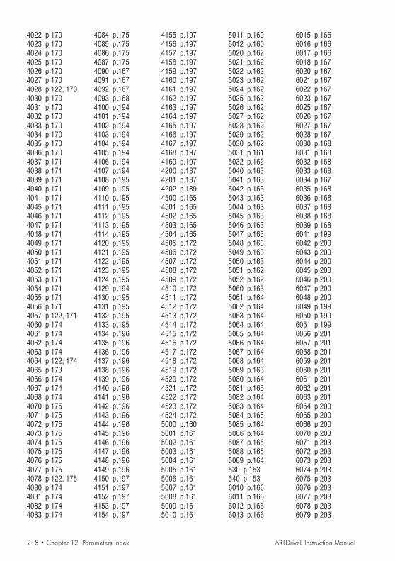
218 • Chapter 12 Parameters Index ARTDriveL Instruction Manual
4022 p.1704023 p.1704024 p.1704025 p.1704026 p.1704027 p.1704028 p.122, 1704030 p.1704031 p.1704032 p.1704033 p.1704034 p.1704035 p.1704036 p.1704037 p.1714038 p.1714039 p.1714040 p.1714041 p.1714045 p.1714046 p.1714047 p.1714048 p.1714049 p.1714050 p.1714051 p.1714052 p.1714053 p.1714054 p.1714055 p.1714056 p.1714057 p.122, 1714060 p.1744061 p.1744062 p.1744063 p.1744064 p.122, 1744065 p.1734066 p.1744067 p.1744068 p.1744070 p.1754071 p.1754072 p.1754073 p.1754074 p.1754075 p.1754076 p.1754077 p.1754078 p.122, 1754080 p.1744081 p.1744082 p.1744083 p.174
4084 p.1754085 p.1754086 p.1754087 p.1754090 p.1674091 p.1674092 p.1674093 p.1684100 p.1944101 p.1944102 p.1944103 p.1944104 p.1944105 p.1944106 p.1944107 p.1944108 p.1954109 p.1954110 p.1954111 p.1954112 p.1954113 p.1954114 p.1954120 p.1954121 p.1954122 p.1954123 p.1954124 p.1954129 p.1944130 p.1954131 p.1954132 p.1954133 p.1954134 p.1964135 p.1964136 p.1964137 p.1964138 p.1964139 p.1964140 p.1964141 p.1964142 p.1964143 p.1964144 p.1964145 p.1964146 p.1964147 p.1964148 p.1964149 p.1964150 p.1974151 p.1974152 p.1974153 p.1974154 p.197
4155 p.1974156 p.1974157 p.1974158 p.1974159 p.1974160 p.1974161 p.1974162 p.1974163 p.1974164 p.1974165 p.1974166 p.1974167 p.1974168 p.1974169 p.1974200 p.1874201 p.1874202 p.1894500 p.1654501 p.1654502 p.1654503 p.1654504 p.1654505 p.1724506 p.1724507 p.1724508 p.1724509 p.1724510 p.1724511 p.1724512 p.1724513 p.1724514 p.1724515 p.1724516 p.1724517 p.1724518 p.1724519 p.1724520 p.1724521 p.1724522 p.1724523 p.1724524 p.1725000 p.1605001 p.1615002 p.1615003 p.1615004 p.1615005 p.1615006 p.1615007 p.1615008 p.1615009 p.1615010 p.161
5011 p.1605012 p.1605020 p.1625021 p.1625022 p.1625023 p.1625024 p.1625025 p.1625026 p.1625027 p.1625028 p.1625029 p.1625030 p.1625031 p.1615032 p.1625040 p.1635041 p.1635042 p.1635043 p.1635044 p.1635045 p.1635046 p.1635047 p.1635048 p.1635049 p.1635050 p.1635051 p.1625052 p.1625060 p.1635061 p.1645062 p.1645063 p.1645064 p.1645065 p.1645066 p.1645067 p.1645068 p.1645069 p.1635080 p.1645081 p.1655082 p.1645083 p.1645084 p.1655085 p.1645086 p.1645087 p.1655088 p.1655089 p.164530 p.153540 p.1536010 p.1666011 p.1666012 p.1666013 p.166
6015 p.1666016 p.1666017 p.1666018 p.1676020 p.1676021 p.1676022 p.1676023 p.1676025 p.1676026 p.1676027 p.1676028 p.1676030 p.1686031 p.1686032 p.1686033 p.1686034 p.1676035 p.1686036 p.1686037 p.1686038 p.1686039 p.1686041 p.1996042 p.2006043 p.2006044 p.2006045 p.2006046 p.2006047 p.2006048 p.2006049 p.1996050 p.1996051 p.1996056 p.2016057 p.2016058 p.2016059 p.2016060 p.2016061 p.2016062 p.2016063 p.2016064 p.2006065 p.2006066 p.2006070 p.2036071 p.2036072 p.2036073 p.2036074 p.2036075 p.2036076 p.2036077 p.2036078 p.2036079 p.203

ARTDriveL Instruction Manual Chapter 12 Parameters Index • 219
6080 p.2036081 p.2036082 p.2046083 p.2046084 p.2046085 p.204670 p.126, 127680 p.126690 p.126, 127700 p.1277029 p.1497030 p.1497031 p.1497032 p.1497033 p.1497034 p.1497035 p.1497036 p.1497037 p.1497038 p.1497039 p.1497040 p.1507041 p.1507045 p.1507046 p.1517050 p.1507051 p.1507053 p.1507060 p.1387061 p.1387062 p.1387063 p.1387064 p.1387065 p.1387066 p.1387067 p.1387069 p.1417070 p.1417072 p.1407073 p.1417074 p.141710 p.1277100 p.1407101 p.1407102 p.1407103 p.1407104 p.1407105 p.1407106 p.1407110 p.1387115 p.1407116 p.1407117 p.1407118 p.142
7134 p.1387135 p.1867136 p.1867137 p.1877138 p.1417141 p.1857142 p.1867143 p.1417144 p.1877145 p.186720 p.127730 p.127775 p.1278021 p.1498022 p.1508031 p.1498040 p.1398041 p.1398042 p.1398043 p.1398044 p.1398046 p.1398047 p.1398050 p.1398051 p.1398052 p.1408053 p.1408054 p.1408056 p.1398057 p.1408078 p.1418090 p.141810 p.1258998 p.1928999 p.1919000 p.1939001 p.1939002 p.1939003 p.1939004 p.1939005 p.1939010 p.1929011 p.1929012 p.1929013 p.1929014 p.1929015 p.1929020 p.1929021 p.1929022 p.1929023 p.1929024 p.1929025 p.1929030 p.193
9031 p.1939032 p.1939033 p.1939034 p.1939035 p.1939040 p.1889041 p.1889042 p.1889043 p.1899044 p.1899046 p.1839047 p.1839049 p.1879050 p.1829051 p.1829052 p.1839053 p.1839054 p.1849055 p.1849056 p.1849057 p.1859058 p.1859059 p.1859060 p.1839061 p.1849062 p.1849063 p.1839064 p.1839065 p.1849066 p.1849067 p.1849068 p.1869071 p.1889072 p.1239073 p.1239074 p.1879075 p.1839076 p.1829086 p.1869087 p.1859088 p.1859089 p.1859090 p.1239095 p.1239099 p.1879100 p.2019101 p.2019102 p.2019103 p.2019104 p.2029105 p.2029106 p.2029107 p.2029108 p.202
9109 p.2029110 p.2029111 p.2029112 p.2029113 p.2029114 p.2029115 p.2029116 p.2029117 p.2029118 p.2029119 p.2029120 p.2029121 p.2029122 p.2029123 p.2029124 p.2029125 p.2029126 p.2039127 p.2039128 p.2039129 p.2039130 p.2039131 p.2039210 p.1599211 p.1599220 p.1889221 p.188930 p.1279340 p.1779341 p.1779342 p.1789343 p.1789344 p.1789345 p.1789346 p.1789347 p.1789348 p.1789349 p.1789350 p.1789351 p.1789352 p.1789353 p.1789354 p.1799355 p.1799356 p.1799360 p.1809361 p.1809362 p.1809363 p.1809364 p.1809365 p.1809366 p.1809367 p.1819368 p.181
9369 p.1819370 p.1819371 p.1819372 p.1819373 p.1819374 p.1819375 p.1819376 p.1819377 p.1819378 p.1819405 p.1229410 p.1319411 p.1309412 p.1309417 p.1309419 p.1309420 p.1309421 p.1409431 p.1469432 p.1469434 p.1479435 p.1479438 p.1479439 p.1479550 p.1339551 p.1339553 p.1239554 p.1239555 p.1239557 p.1339600 p.1849603 p.1849604 p.1849605 p.1859606 p.1859608 p.1889610 p.1899611 p.1899612 p.1899614 p.1899615 p.1899616 p.1899630 p.1899631 p.1899632 p.1899634 p.1899635 p.1909636 p.1909640 p.1839641 p.183970 p.12798 p.125980 p.12799 p.125
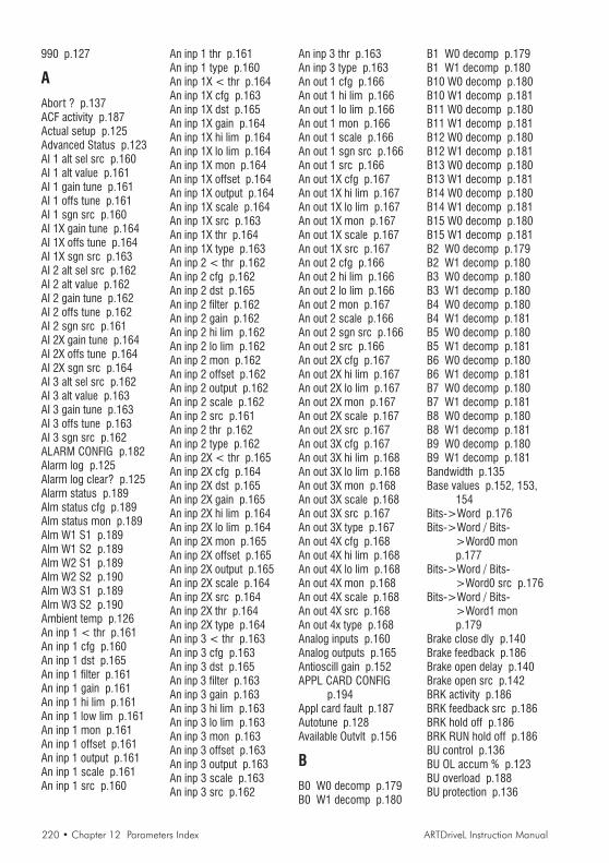
220 • Chapter 12 Parameters Index ARTDriveL Instruction Manual
990 p.127
AAbort ? p.137ACF activity p.187Actual setup p.125Advanced Status p.123AI 1 alt sel src p.160AI 1 alt value p.161AI 1 gain tune p.161AI 1 offs tune p.161AI 1 sgn src p.160AI 1X gain tune p.164AI 1X offs tune p.164AI 1X sgn src p.163AI 2 alt sel src p.162AI 2 alt value p.162AI 2 gain tune p.162AI 2 offs tune p.162AI 2 sgn src p.161AI 2X gain tune p.164AI 2X offs tune p.164AI 2X sgn src p.164AI 3 alt sel src p.162AI 3 alt value p.163AI 3 gain tune p.163AI 3 offs tune p.163AI 3 sgn src p.162ALARM CONFIG p.182Alarm log p.125Alarm log clear? p.125Alarm status p.189Alm status cfg p.189Alm status mon p.189Alm W1 S1 p.189Alm W1 S2 p.189Alm W2 S1 p.189Alm W2 S2 p.190Alm W3 S1 p.189Alm W3 S2 p.190Ambient temp p.126An inp 1 < thr p.161An inp 1 cfg p.160An inp 1 dst p.165An inp 1 filter p.161An inp 1 gain p.161An inp 1 hi lim p.161An inp 1 low lim p.161An inp 1 mon p.161An inp 1 offset p.161An inp 1 output p.161An inp 1 scale p.161An inp 1 src p.160
An inp 1 thr p.161An inp 1 type p.160An inp 1X < thr p.164An inp 1X cfg p.163An inp 1X dst p.165An inp 1X gain p.164An inp 1X hi lim p.164An inp 1X lo lim p.164An inp 1X mon p.164An inp 1X offset p.164An inp 1X output p.164An inp 1X scale p.164An inp 1X src p.163An inp 1X thr p.164An inp 1X type p.163An inp 2 < thr p.162An inp 2 cfg p.162An inp 2 dst p.165An inp 2 filter p.162An inp 2 gain p.162An inp 2 hi lim p.162An inp 2 lo lim p.162An inp 2 mon p.162An inp 2 offset p.162An inp 2 output p.162An inp 2 scale p.162An inp 2 src p.161An inp 2 thr p.162An inp 2 type p.162An inp 2X < thr p.165An inp 2X cfg p.164An inp 2X dst p.165An inp 2X gain p.165An inp 2X hi lim p.164An inp 2X lo lim p.164An inp 2X mon p.165An inp 2X offset p.165An inp 2X output p.165An inp 2X scale p.164An inp 2X src p.164An inp 2X thr p.164An inp 2X type p.164An inp 3 < thr p.163An inp 3 cfg p.163An inp 3 dst p.165An inp 3 filter p.163An inp 3 gain p.163An inp 3 hi lim p.163An inp 3 lo lim p.163An inp 3 mon p.163An inp 3 offset p.163An inp 3 output p.163An inp 3 scale p.163An inp 3 src p.162
An inp 3 thr p.163An inp 3 type p.163An out 1 cfg p.166An out 1 hi lim p.166An out 1 lo lim p.166An out 1 mon p.166An out 1 scale p.166An out 1 sgn src p.166An out 1 src p.166An out 1X cfg p.167An out 1X hi lim p.167An out 1X lo lim p.167An out 1X mon p.167An out 1X scale p.167An out 1X src p.167An out 2 cfg p.166An out 2 hi lim p.166An out 2 lo lim p.166An out 2 mon p.167An out 2 scale p.166An out 2 sgn src p.166An out 2 src p.166An out 2X cfg p.167An out 2X hi lim p.167An out 2X lo lim p.167An out 2X mon p.167An out 2X scale p.167An out 2X src p.167An out 3X cfg p.167An out 3X hi lim p.168An out 3X lo lim p.168An out 3X mon p.168An out 3X scale p.168An out 3X src p.167An out 3X type p.167An out 4X cfg p.168An out 4X hi lim p.168An out 4X lo lim p.168An out 4X mon p.168An out 4X scale p.168An out 4X src p.168An out 4x type p.168Analog inputs p.160Analog outputs p.165Antioscill gain p.152APPL CARD CONFIG
p.194Appl card fault p.187Autotune p.128Available Outvlt p.156
BB0 W0 decomp p.179B0 W1 decomp p.180
B1 W0 decomp p.179B1 W1 decomp p.180B10 W0 decomp p.180B10 W1 decomp p.181B11 W0 decomp p.180B11 W1 decomp p.181B12 W0 decomp p.180B12 W1 decomp p.181B13 W0 decomp p.180B13 W1 decomp p.181B14 W0 decomp p.180B14 W1 decomp p.181B15 W0 decomp p.180B15 W1 decomp p.181B2 W0 decomp p.179B2 W1 decomp p.180B3 W0 decomp p.180B3 W1 decomp p.180B4 W0 decomp p.180B4 W1 decomp p.181B5 W0 decomp p.180B5 W1 decomp p.181B6 W0 decomp p.180B6 W1 decomp p.181B7 W0 decomp p.180B7 W1 decomp p.181B8 W0 decomp p.180B8 W1 decomp p.181B9 W0 decomp p.180B9 W1 decomp p.181Bandwidth p.135Base values p.152, 153,
154Bits->Word p.176Bits->Word / Bits-
>Word0 monp.177
Bits->Word / Bits->Word0 src p.176
Bits->Word / Bits->Word1 monp.179
Brake close dly p.140Brake feedback p.186Brake open delay p.140Brake open src p.142BRK activity p.186BRK feedback src p.186BRK hold off p.186BRK RUN hold off p.186BU control p.136BU OL accum % p.123BU overload p.188BU protection p.136

ARTDriveL Instruction Manual Chapter 12 Parameters Index • 221
BU res cont pwr p.136BU res OL factor p.136BU res OL time p.136BU resistance p.136BUOL activity p.188
CCabin weight p.129Calc Inertia p.135Calc method p.134CCF activity p.187CCF restart p.187CCF restart time p.187Cmp 1 delay p.200Cmp 1 function p.200Cmp 1 inp 0 p.199Cmp 1 inp 0 src p.199Cmp 1 inp 1 p.200Cmp 1 inp 1 src p.199Cmp 1 inp 2 p.200Cmp 1 inp 2 src p.199Cmp 1 inversion p.200Cmp 1 window p.200Cmp 2 delay p.201Cmp 2 function p.201Cmp 2 inp 0 p.201Cmp 2 inp 0 src p.200Cmp 2 inp 1 p.201Cmp 2 inp 1 src p.200Cmp 2 inp 2 p.201Cmp 2 inp 2 src p.200Cmp 2 inversion p.201Cmp 2 window p.201CNT activity p.186CNT feedback src p.185CNT hold off p.186Comm card fault p.187Commands p.159Commands cfg p.159Commands mon p.160Commands select p.159Commands src p.159COMMUNICATION p.191Compare 1 p.199Compare 1 cfg p.199Compare 1 mon p.200Compare 1 output p.200Compare 1 src p.199Compare 2 p.200Compare 2 cfg p.201Compare 2 mon p.201Compare 2 output p.201Compare 2 src p.200
Complete rot p.128Complete still p.128Connect p.203Connect A p.203Connect B p.203ConnectA inp 0 src p.203ConnectA inp 1 src p.203ConnectA inp 2 src p.203ConnectA inp 3 src p.203ConnectA inp 4 src p.203ConnectA inp 5 src p.203ConnectA inp 6 src p.203ConnectA inp 7 src p.203ConnectB inp 0 src p.203ConnectB inp 1 src p.203ConnectB inp 2 src p.203ConnectB inp 3 src p.203ConnectB inp 4 src p.204ConnectB inp 5 src p.204ConnectB inp 6 src p.204ConnectB inp 7 src p.204Cont close delay p.140Cont open delay p.140Contact feedback p.185Cosfi p.127Counter weight p.129CPU1 runtime p.124CPU2 runtime p.124Curr regulato p.153CurrI base value p.153CurrI gain % p.153CurrP base value p.153CurrP gain % p.153CurrReg p.128CUSTOM FUNCTIONS
p.199
DDC braking p.148DC link voltage p.123DCbrake cmd src p.121,
148DCbrake current p.148DCbrake delay p.148DCbrake duration p.148DCBrake state p.148Dead time limit p.153Dead time slope p.153Destinations p.172DGFC async Ch p.195DGFC config p.194DGFC enable p.194DGFC sync Ch p.194,
195, 196, 197DGFC-A Drv W0mon
p.197DGFC-A Drv W1mon
p.197DGFC-A Drv W2mon
p.197DGFC-A Drv W3mon
p.197DGFC-A Drv W4mon
p.197DGFC-A Drv W5mon
p.197DGFC-A Drv W6mon
p.197DGFC-A Drv W7mon
p.197DGFC-A Drv W8mon
p.197DGFC-A Drv W9mon
p.197DGFC-S Drv W0mon
p.195DGFC-S Drv W1mon
p.195DGFC-S Drv W2mon
p.195DGFC-S Drv W3mon
p.195DGFC-S Drv W4mon
p.195DI 0X inversion p.170DI 0X monitor p.171DI 1X inversion p.170DI 1X monitor p.171DI 2X inversion p.170DI 2X monitor p.171DI 3X inversion p.170DI 3X monitor p.171DI 4X inversion p.170DI 4X monitor p.171DI 5X inversion p.170DI 5X monitor p.171DI 6X inversion p.170DI 6X monitor p.171DI 7X inversion p.171DI 7X monitor p.171DI 8X inversion p.171DI 8X monitor p.171DI 9X inversion p.171DI 9X monitor p.171DI 0 Enable dst p.172DI 0 Enable mon p.170DI 0X dst p.172
DI 1 dst p.172DI 1 inversion p.169DI 1 monitor p.170DI 10X dst p.172DI 10X inversion p.171DI 10X monitor p.171DI 11X dst p.172DI 11X inversion p.171DI 11X monitor p.171DI 1X dst p.172DI 2 dst p.172DI 2 inversion p.169DI 2 monitor p.170DI 2X dst p.172DI 3 dst p.172DI 3 inversion p.169DI 3 monitor p.170DI 3X dst p.172DI 4 dst p.172DI 4 inversion p.169DI 4 monitor p.170DI 4X dst p.172DI 5 dst p.172DI 5 inversion p.169DI 5 monitor p.170DI 5X dst p.172DI 6 dst p.172DI 6 inversion p.169DI 6 monitor p.170DI 6X dst p.172DI 7 dst p.172DI 7 inversion p.170DI 7 monitor p.170DI 7654321E p.122, 170DI 7X dst p.172DI 8X dst p.172DI 9X dst p.172Dig Enable src p.159Dig pad 0 p.202Dig pad 1 p.202Dig pad 10 p.203Dig pad 11 p.203Dig pad 12 p.203Dig pad 13 p.203Dig pad 14 p.203Dig pad 15 p.203Dig pad 2 p.202Dig pad 3 p.202Dig pad 4 p.202Dig pad 5 p.202Dig pad 6 p.202Dig pad 7 p.202Dig pad 8 p.202Dig pad 9 p.202
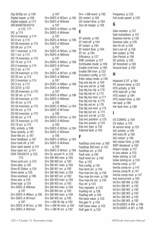
222 • Chapter 12 Parameters Index ARTDriveL Instruction Manual
Dig StrStp src p.159Digital inputs p.169Digital outputs p.173DIX BA9876543210
p.122, 171DO p.174DO 0 inversion p.174DO 0 src p.173DO 0X inversion p.175DO 0X src p.174DO 1 inversion p.174DO 1 src p.174DO 1X inversion p.175DO 1X src p.174DO 2 inversion p.174DO 2 src p.174DO 2X inversion p.175DO 2X src p.174DO 3 inversion p.174DO 3 src p.174DO 3210 p.122DO 3X inversion p.175DO 3X src p.174DO 4X inversion p.175DO 4X src p.175DO 5X inversion p.175DO 5X src p.175DO 6X inversion p.175DO 6X src p.175DO 7X inversion p.175DO 7X src p.175DOL activity p.188Door activity p.187Door fbk src p.187Door feedback p.187Door hold off p.187Door open speed p.141Door open src p.141DOX 76543210 p.122,
175Drive cont curr p.124Drive data p.126Drive ID Status p.124Drive name p.125Drive overload p.188Drive size p.124Drive type p.124Drv DGFC-A W0mon
p.197Drv DGFC-A W0src p.195Drv DGFC-A W1mon
p.197Drv DGFC-A W1src p.195Drv DGFC-A W2mon
p.197Drv DGFC-A W2src p.195Drv DGFC-A W3mon
p.197Drv DGFC-A W3src p.195Drv DGFC-A W4mon
p.197Drv DGFC-A W4src p.196Drv DGFC-A W5mon
p.197Drv DGFC-A W5src p.196Drv DGFC-A W6mon
p.197Drv DGFC-A W6src p.196Drv DGFC-A W7mon
p.197Drv DGFC-A W7src p.196Drv DGFC-A W8mon
p.197Drv DGFC-A W8src p.196Drv DGFC-A W9mon
p.197Drv DGFC-A W9src p.196Drv DGFC-S W0mon
p.195Drv DGFC-S W0src p.194Drv DGFC-S W1mon
p.195Drv DGFC-S W1src p.194Drv DGFC-S W2mon
p.195Drv DGFC-S W2src p.194Drv DGFC-S W3mon
p.195Drv DGFC-S W3src p.194Drv DGFC-S W4mon
p.195Drv DGFC-S W4src p.194Drv OL accum % p.123Drv SBI W0 mon p.193Drv SBI W0 src p.192Drv SBI W1 mon p.193Drv SBI W1 src p.192Drv SBI W2 mon p.193Drv SBI W2 src p.192Drv SBI W3 mon p.193Drv SBI W3 src p.192Drv SBI W4 mon p.193Drv SBI W4 src p.192Drv SBI W5 mon p.193Drv SBI W5 src p.192Drv->SBI W cfg p.192Drv->SBI W mon p.193Drv->SBI W src p.192
Drv->SBI word p.192DS restart p.183DS restart time p.183Dyn vlt margin p.156
EEF activity p.183EF hold off p.184EF restart p.184EF restart time p.184EF src p.183Efficiency p.127EMF constant p.127En/Disable mode p.159Enable cmd mon p.160Enable SM mon p.122Encoders config p.131Enter setup mode p.126Exp ana inp en p.165Exp ana out en p.168Exp dig inp cfg p.170Exp dig inp en p.172Exp dig inp mon p.171Exp dig out cfg p.175Exp dig out en p.176Exp dig out mon p.175Exp dig out src p.174Exp enc cnt dir p.133Exp enc position p.123Exp enc pulses p.133Exp enc type p.132External fault p.183
F
FastStop cmd mon p.160FastStop SM mon p.122FastStop src p.159Fault rese p.182Fault reset src p.182Flux p.123Flux config p.155Flux level src p.155Flux max lim cfg p.156Flux max lim mon p.156Flux max lim src p.155Flux ref p.123Flux regulator p.153FluxReg rot p.128FluxReg still p.128FlxI base value p.153FlxI gain % p.153FlxP base value p.153FlxP gain % p.153
Frequency p.122Full scale speed p.129
GGain monitor p.157Gain transitions p.157Gearbox inertia p.130Gearbox ratio p.129Gen Hi ref p.158Gen Low ref p.158Gen output p.158Gen Period p.158GF activity p.183GF threshold p.183Ground fault p.183
HHeatsink S OT p.184HT sensor temp p.123HTS activity p.184HTS hold off p.184HTS restart p.184HTS restart time p.184Hw fault p.189Hw fault mon p.189
II/O CONFIG p.159I/O status p.122IA sensor temp p.123IAS activity p.185IAS hold off p.185IAS restart p.185IAS restar t time p.185IGBT desaturat p.183Import recipe p.137In use values p.153Index storing p.133Index storing en p.133Inertia comp p.147Inertia comp en p.147Inertia comp flt p.147Inertia comp mon p.147Inst overcurrent p.183Int Drv SBI W0 p.192Int Drv SBI W1 p.192Int Drv SBI W2 p.192Int Drv SBI W3 p.192Int Drv SBI W4 p.192Int Drv SBI W5 p.192Int DrvDGFC-A W0 p.196Int DrvDGFC-A W1 p.196

ARTDriveL Instruction Manual Chapter 12 Parameters Index • 223
Int DrvDGFC-A W2 p.196Int DrvDGFC-A W3 p.196Int DrvDGFC-A W4 p.196Int DrvDGFC-A W5 p.196Int DrvDGFC-A W6 p.196Int DrvDGFC-A W7 p.196Int DrvDGFC-A W8 p.196Int DrvDGFC-A W9 p.196Int DrvDGFC-S W0 p.194Int DrvDGFC-S W1 p.194Int DrvDGFC-S W2 p.194Int DrvDGFC-S W3 p.195Int DrvDGFC-S W4 p.195Int flx maxlim p.156Int Inertia p.147Int IS ctrl p.133Int Outvlt lim p.156Int Pre-torque p.146Int ramp ref 1 p.149Int ramp ref 2 p.149Int ramp ref 3 p.149Int speed ref 1 p.150Int speed ref 2 p.150Int torque ref 2 p.154Intake air S OT p.185Inuse flx maxlim p.156Inuse Outvlt ref p.156Inuse S I gain p.157Inuse S P gain p.157InUse SpdI gain% p.153InUse SpdP gain% p.153Inuse Tcurr lim+ p.155Inuse Tcurr lim- p.155IOC restart p.183IOC restart time p.183IS ctrl src p.133
LLanding control p.130Landing distance p.130Landing init src p.130Landing ratio p.130Landing zone p.130Last SBI error p.192Life time p.125Lift sequence p.140Load default ? p.137Load setup p.129Load weight p.129Lock flux pos p.155LS inductance p.127
MMagn curr ref p.123Magn ramp time p.155Magnetiz config p.155Magnetizing curr p.123Mains voltage p.126Mask W1 S1 p.189Mask W1 S2 p.189Mask W2 S1 p.189Mask W2 S2 p.189Mask W3 S1 p.189Mask W3 S2 p.189Max linear speed p.138Measured DTL p.128Measured DTS p.128, 129Measured LsSigma p.128,
129Measured Rs p.128Mechanical data p.129Mlt ramp s0 src p.141Mlt ramp sel mon p.141Mlt spd out mon p.141Mlt spd s 0 src p.140Mlt spd s 1 src p.141Mlt spd s 2 src p.141Mlt spd sel mon p.141MOL activity p.188MONITOR p.122MOT activity p.184MOT hold off p.184Mot OL accum p.135Mot OL accum % p.123Mot OL trip p.135MOT restart p.184MOT restart time p.184Motor data p.126, 127Motor inertia p.129Motor OL control p.135Motor OL factor p.135Motor OL time p.135Motor OT p.184Motor overload p.188Motor pp/sens pp p.134Motor protection p.135Motoring gains p.156MR0 acc end jerk p.139MR0 acc ini jerk p.139MR0 acceleration p.139MR0 dec end jerk p.139MR0 dec ini jerk p.139MR0 deceleration p.139MR0 end decel p.139MR1 acc end jerk p.139
MR1 acc ini jerk p.139MR1 acceleration p.139MR1 dec end jerk p.140MR1 dec ini jerk p.140MR1 deceleration p.140MR1 end decel p.140Multi speed 0 p.138Multi speed 1 p.138Multi speed 2 p.138Multi speed 3 p.138Multi speed 4 p.138Multi speed 5 p.138Multi speed 6 p.138Multi speed 7 p.138
NNorm Exp enc spd p.123Norm Speed p.122Norm Std enc spd p.123
OObserver filter p.157Observer ref mon p.157OS activity p.188OS hold off p.188OS threshold p.188Out vlt ref cfg p.156Out vlt ref mon p.156Out vlt ref src p.156Output current p.122Output power p.122Output vlt ref p.156Output voltage p.122Outvlt lim src p.156OV restart p.183OV restart time p.183Overspeed p.188Overvoltage p.183
PPad 0 p.201Pad 1 p.201Pad 10 p.202Pad 11 p.202Pad 12 p.202Pad 13 p.202Pad 14 p.202Pad 15 p.202Pad 2 p.201Pad 3 p.201Pad 4 p.202Pad 5 p.202
Pad 6 p.202Pad 7 p.202Pad 8 p.202Pad 9 p.202Pad param bit p.202Pad param word p.201Pad parameters p.201Percent values p.152, 153Pole pairs p.127Pos P gain p.130Pos speed limit p.131Pre-torque p.146Pre-torque gain p.147Pre-torque src p.147Pre-torque time p.146Pre-torque type p.147Pre-trq sign src p.147Prop filter p.145Protocol type p.191Pulley diameter p.129
RRamp function p.149Ramp out enable p.149Ramp out mon p.150Ramp profile p.138Ramp ref p.122Ramp ref 1 mon p.149Ramp ref 1 src p.149Ramp ref 2 mon p.149Ramp ref 2 src p.149Ramp ref 3 mon p.149Ramp ref 3 src p.149Ramp ref cfg p.149Ramp ref inv src p.149Ramp ref mon p.149Ramp ref src p.149Ramp setpoint p.149Ramp shape p.149Rated current p.126, 127Rated frequency p.126Rated power p.127Rated speed p.127Rated voltage p.126, 127Regen gains p.157Regulation mode p.137REGULATION PARAM
p.152Regulation S OT p.185Rep/Sim enc sel p.133Rep/Sim encoder p.133Results p.128RG sensor temp p.123

224 • Chapter 12 Parameters Index ARTDriveL Instruction Manual
RGS activity p.185RGS hold off p.185RGS restart p.185RGS restart time p.185Rope weight p.129RS485 p.191
SS mot HPgain p.156, 157Save config ? p.137SAVE PARAMETERS
p.151, 158, 181,193, 198, 204
SBI config p.191SBI Drv W0 mon p.193SBI Drv W1 mon p.193SBI Drv W2 mon p.193SBI Drv W3 mon p.193SBI Drv W4 mon p.193SBI Drv W5 mon p.193SBI enable p.191SBI monitor p.192SBI->Drv W mon p.193SBI->Drv word p.193Seq start mode p.140Seq start sel p.140Sequencer status p.123SERVICE p.205Service factor p.135Sfbk der base p.145Sfbk der enable p.144Sfbk der filter p.145Sfbk der gain p.145SFL activity p.188SGP tran21 band p.146SGP tran21 h thr p.146SGP tran32 band p.146SGP tran32 l thr p.146Slave address p.191Slave res time p.191Slip comp p.152Slip comp filter p.152Slip comp mode p.152Slip I gain p.152Slip P gain p.152SlowDown dist p.140Sls SpdFbk gains p.156Smooth start spd p.138Smooth str time p.140Software status p.125Software type p.125Software version V .
p.125Spd 0 dis dly p.160
Spd 0 enable p.144Spd 0 I gain % p.144Spd 0 P gain % p.144Spd 0 ref delay p.145Spd 0 ref thr p.145Spd 0 spd delay p.145Spd 0 speed thr p.145Spd fbk loss p.188Spd ref/fbk res p.126Spd regulator p.152SpdI base value p.152SpdI1 gain % p.144, 152SpdI2 gain % p.144SpdI3 gain % p.144SpdP base value p.152SpdP1 gain % p.144, 152SpdP2 gain % p.144SpdP3 gain % p.144SpdReg gain calc p.134Speed fbk sel p.131Speed profile p.138Speed ref p.122Speed ref 1 mon p.150Speed ref 1 src p.150Speed ref 2 mon p.151Speed ref 2 src p.150Speed ref cfg p.150Speed ref mon p.150Speed reg gains p.142Speed setpoint p.150Speed threshold p.145Speedref inv src p.150Star t alt src p.140Star t cmd mon p.160Star t fwd src p.140Star t rev src p.140Star t SM mon p.122STARTUP p.126Stator resistance p.127Std dig enc mode p.132Std dig inp cfg p.169Std dig inp mon p.170Std dig out cfg p.174Std dig out mon p.174Std dig out src p.173Std enc cnt dir p.132Std enc position p.123Std enc pulses p.132Std enc supply p.132Std enc type p.131Std sin enc mod p.123Std sin enc Vp p.132Switching freq p.126Sys time-ddmmyy p.125
TT setpoint cfg p.154T setpoint mon p.154T setpoint src p.154Tcurr lim + p.154Tcurr lim - p.155Tcurr lim sel p.154Tcurr lim state p.155Term Start src p.159Term Stop src p.159Term StrStp src p.159Test gen cfg p.158Test gen mode p.158Test gen mon p.158Test generator p.157Torque config p.154Torque constant p.127Torque curr p.123Torque curr ref p.123Torque ref p.154Torque ref 2 mon p.154Torque ref 2 src p.154TRAVEL p.138Travel units sel p.129Trq curr lim cfg p.154Trq curr lim mon p.155Trq curr lim src p.154
UUndervoltage p.182UV repetitive p.189UV restart p.182UV restart time p.182UV select src p.182UVR attempts p.189UVR delay p.189
VV ILim I gain p.152V ILim P gain p.152V reg param p.152V/f config p.135V/f frequency p.135V/f voltage p.135Vlt regulator p.153VltI base value p.154VltI gain % p.153VltP base value p.154VltP gain % p.153Voltage boost p.152
WW0 comp out p.177W0 decomp inp p.179W0 decomp mon p.179W0 decomp src p.179W1 comp out p.179W1 decomp inp p.180W1 decomp mon p.180W1 decomp src p.180Weights p.129Word->Bits p.179Word0 B0 src p.176Word0 B1 src p.176Word0 B10 src p.177Word0 B11 src p.177Word0 B12 src p.177Word0 B13 src p.177Word0 B14 src p.177Word0 B15 src p.177Word0 B2 src p.176Word0 B3 src p.176Word0 B4 src p.176Word0 B5 src p.176Word0 B6 src p.176Word0 B7 src p.177Word0 B8 src p.177Word0 B9 src p.177Word0->Bits cfg p.179Word0->Bits mon p.179Word0->Bits src p.179Word1 B0 src p.177Word1 B1 src p.177Word1 B10 src p.178Word1 B11 src p.178Word1 B12 src p.178Word1 B13 src p.178Word1 B14 src p.179Word1 B15 src p.179Word1 B2 src p.178Word1 B3 src p.178Word1 B4 src p.178Word1 B5 src p.178Word1 B6 src p.178Word1 B7 src p.178Word1 B8 src p.178Word1 B9 src p.178Word1->Bits cfg p.180Word1->Bits mon p.180Word1->Bits src p.180

SIEI worldwide
Germany:SIEI-AREG – GemmrigheimTel. +49 – 7143 – 9730E-mail [email protected]
France:SIEI FRANCE – SaverneTel. +33 – 3 – 88 02 14 14E-mail [email protected]
England:SIEI UK – TelfordTel. +44 – 1952 – 604555E-mail [email protected]
Slovenia:SIEI EST – LjubljanaTel. +386 – 611 614 940E-mail [email protected]
SIEI
Via Carducci 2421040 Gerenzano VA – ItaliaTel. +39 – 02.967.601Fax +39 – 02.968.26.53
Information:E-mail [email protected]
Technical Assistance:E-mail [email protected]
Internet www.sieigroup.com
SIE
I w
orl
dw
ide
SIEI – A member of the GEFRAN Group.
GEFRAN S.p.A.Via Sebina 7425050 Provaglio d’Iseo (BS) – ItaliaTel. +39 – 030.9888.1Fax +39 – 030.9839063E-mail [email protected] www.gefran.com
Asia:GEFRAN SIEI ASIA – SingaporeTel. +65 – 6 – 8418.300E-mail [email protected]
SIEI ASIA – ShanghaiTel. +86 – 21 – 6916.9898E-mail [email protected]
USA:SIEI AMERICA – Charlotte, NC 28208Tel. +1 – 704 – 329.0200E-mail [email protected]
SIEI Customer ServiceE-mail [email protected]. +39 – 02.967.60.500Fax +39 – 02.967.60.278