Gear
19
POWER TRANSMISSION Power transmission is the movement of energy from its place of generation to a location where it is applied to performing useful work. Power transmission is normally accomplished by belts, ropes, chains, gears, couplings and friction clutches. GEAR A toothed wheel that engages another toothed mechanism in order to change the speed or direction of transmitted motion. A gear is a component within a transmission device that transmits rotational force to another gear or device. A gear is different from a pulley in that a gear is a round wheel which has linkages ("teeth" or "cogs") that mesh with other gear teeth, allowing force to be fully transferred without slippage. Depending on their construction and arrangement, geared devices can transmit forces at different speeds , torques , or in a different direction, from the power source. The most common situation is for a gear to mesh with another gear Gear’s most important feature is that gears of unequal sizes (diameters) can be combined to produce a mechanical advantage , so that the rotational speed and torque of the second gear are different from that of the first.
-
Upload
rakeshmec325 -
Category
Automotive
-
view
139 -
download
2
Transcript of Gear

POWER TRANSMISSION
Power transmission is the movement of energy from its place of generation to a location
where it is applied to performing useful work. Power transmission is normally
accomplished by belts, ropes, chains, gears, couplings and friction clutches.
GEAR
A toothed wheel that engages another toothed mechanism in order to change the speed or
direction of transmitted motion.
A gear is a component within a transmission device that transmits rotational force to
another gear or device. A gear is different from a pulley in that a gear is a round wheel
which has linkages ("teeth" or "cogs") that mesh with other gear teeth, allowing force to
be fully transferred without slippage. Depending on their construction and arrangement,
geared devices can transmit forces at different speeds, torques, or in a different direction,
from the power source. The most common situation is for a gear to mesh with another
gear
Gear’s most important feature is that gears of unequal sizes (diameters) can be combined
to produce a mechanical advantage, so that the rotational speed and torque of the second
gear are different from that of the first.
To overcome the problem of slippage as in belt drives, gears are used which produce
positive drive with uniform angular velocity.
GEAR CLASSIFICATION
Gears or toothed wheels may be classified as follows:
1. According to the position of axes of the shafts.
The axes of the two shafts between which the motion is to be transmitted, may be
a. Parallel
b. Intersecting
c. Non-intersecting and Non-parallel
Gears for connecting parallel shafts
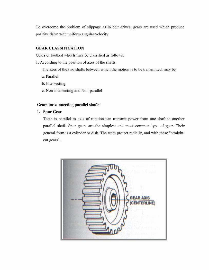
1. Spur Gear
Teeth is parallel to axis of rotation can transmit power from one shaft to another
parallel shaft. Spur gears are the simplest and most common type of gear. Their
general form is a cylinder or disk. The teeth project radially, and with these "straight-
cut gears".

Spur gears are gears in the same plane that move opposite of each other because they
are meshed together. Gear ‘A’ is called the ‘driver’ because this is turned by a motor.
As gear ‘A’ turns it meshes with gear ‘B’ and it begins to turn as well. Gear ‘B’ is
called the ‘driven’ gear.
EXTERNAL AND INTERNAL SPUR GEAR
External gear makes external contact, and the internal gear (right side pair) makes internal
contact.

APPLICATIONS OF SPUR GEAR
Electric screwdriver, dancing monster, oscillating sprinkler, windup alarm clock, washing
machine and clothes dryer
2. Parallel Helical Gear
The teeth on helical gears are cut at an angle to the face of the gear. When two teeth on a
helical gear system engage, the contact starts at one end of the tooth and gradually spreads as the
gears rotate, until the two teeth are in full engagement.
This gradual engagement makes helical gears operate much more smoothly and quietly than spur
gears. For this reason, helical gears are used in almost all car transmissions. Because of the angle
of the teeth on helical gears, they create a thrust load on the gear when they mesh. Devices that
use helical gears have bearings that can support this thrust load.
One interesting thing about helical gears is that if the angles of the gear teeth are correct, they
can be mounted on perpendicular shafts, adjusting the rotation angle by 90 degrees.
CROSSED HELICAL GEAR

Herringbone gears:
To avoid axial thrust, two helical gears of opposite hand can be mounted side by side, to
cancel resulting thrust forces. These are called double helical or herringbone gears
Herringbone gears (or double-helical gears)
Applications of Herringbone Gears
The most common application is in power transmission. They utilize curved teeth for
efficient, high capacity power transmission. This offers reduced pulsation due to which they are
highly used for extrusion and polymerization. Herringbone gears are mostly used on heavy
machinery.
3. Rack and pinion
Rack and pinion gears are used to convert rotation (From the pinion) into linear motion
(of the rack). A perfect example of this is the steering system on many cars. The steering wheel
rotates a gear which engages the rack. As the gear turns, it slides the rack either to the right or
left, depending on which way you turn the wheel. Rack and pinion gears are also used in some
scales to turn the dial that displays your weight.

RACK AND PINION
GEARS FOR CONNECTING INTERSECTING SHAFTS
1. Straight Bevel Gear
Bevel gears are useful when the direction of a shaft's rotation needs to be changed. They are
usually mounted on shafts that are 90 degrees apart, but can be designed to work at other angles
as well. The teeth on bevel gears can be straight, spiral or hypoid. Straight bevel gear teeth
actually have the same problem as straight spur gear teeth as each tooth engages, it impacts the
corresponding tooth all at once.
BEVEL GEAR
Just like with spur gears, the solution to this problem is to curve the gear teeth. These spiral teeth
engage just like helical teeth: the contact starts at one end of the gear and progressively spreads
across the whole tooth.
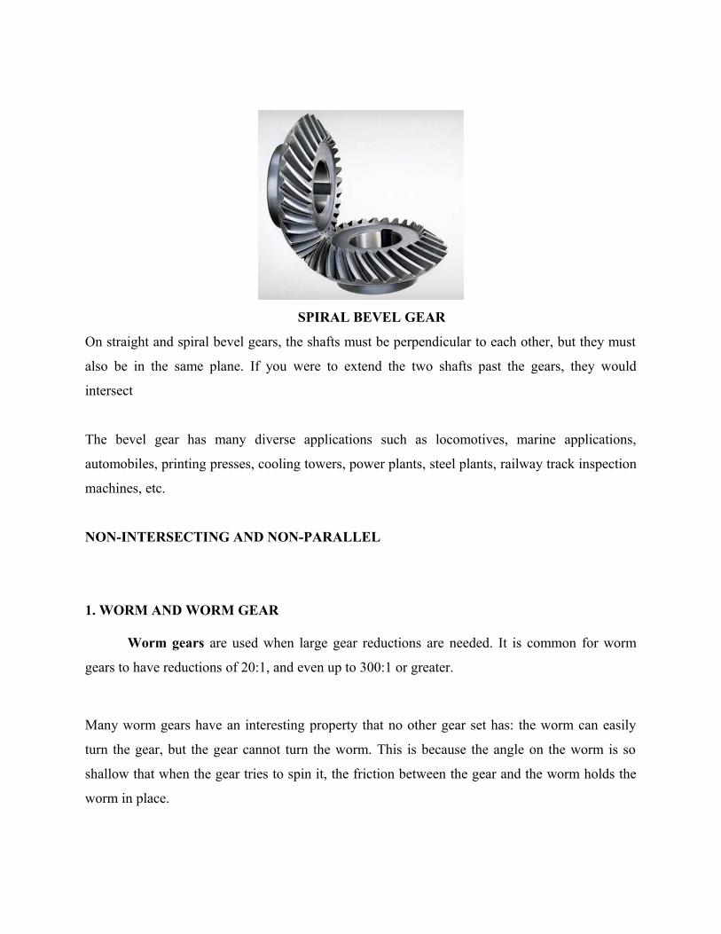
SPIRAL BEVEL GEAR
On straight and spiral bevel gears, the shafts must be perpendicular to each other, but they must
also be in the same plane. If you were to extend the two shafts past the gears, they would
intersect
The bevel gear has many diverse applications such as locomotives, marine applications,
automobiles, printing presses, cooling towers, power plants, steel plants, railway track inspection
machines, etc.
NON-INTERSECTING AND NON-PARALLEL
1. WORM AND WORM GEAR
Worm gears are used when large gear reductions are needed. It is common for worm
gears to have reductions of 20:1, and even up to 300:1 or greater.
Many worm gears have an interesting property that no other gear set has: the worm can easily
turn the gear, but the gear cannot turn the worm. This is because the angle on the worm is so
shallow that when the gear tries to spin it, the friction between the gear and the worm holds the
worm in place.
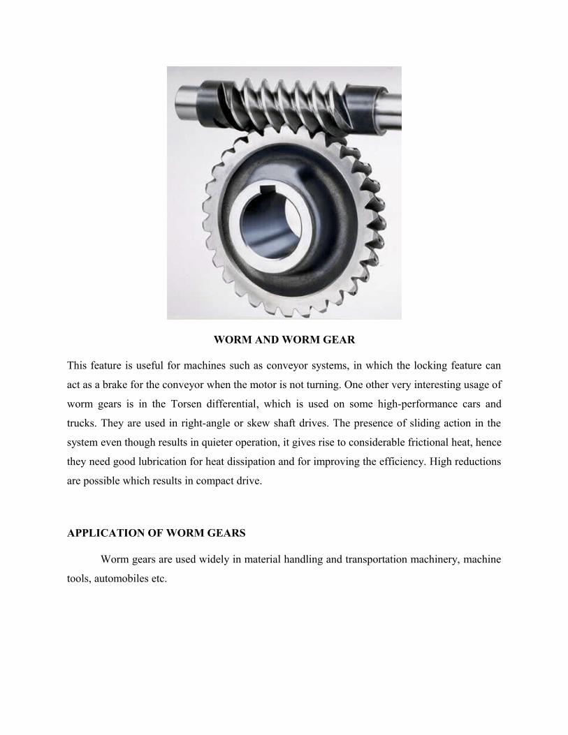
WORM AND WORM GEAR
This feature is useful for machines such as conveyor systems, in which the locking feature can
act as a brake for the conveyor when the motor is not turning. One other very interesting usage of
worm gears is in the Torsen differential, which is used on some high-performance cars and
trucks. They are used in right-angle or skew shaft drives. The presence of sliding action in the
system even though results in quieter operation, it gives rise to considerable frictional heat, hence
they need good lubrication for heat dissipation and for improving the efficiency. High reductions
are possible which results in compact drive.
APPLICATION OF WORM GEARS
Worm gears are used widely in material handling and transportation machinery, machine
tools, automobiles etc.

NOMENCLATURE OF SPUR GEARS
NOMENCLATURE OF SPUR GEAR
In the following section, we define many of the terms used in the analysis of spur gears.
• Pitch surface: The surface of the imaginary rolling cylinder (cone, etc.) that the toothed
gear may be considered to replace.
• Pitch circle: A right section of the pitch surface.
• Addendum circle: A circle bounding the ends of the teeth, in a right section of the gear.
• Root (or dedendum) circle: The circle bounding the spaces between the teeth, in a right
section of the gear.
• Addendum: The radial distance between the pitch circle and the addendum circle.
• Dedendum: The radial distance between the pitch circle and the root circle.
• Clearance: The difference between the dedendum of one gear and the addendum of the
mating gear.

• Face of a tooth: That part of the tooth surface lying outside the pitch surface.
• Flank of a tooth: The part of the tooth surface lying inside the pitch surface.
• Circular thickness (also called the tooth thickness): The thickness of the tooth
measured on the pitch circle. It is the length of an arc and not the length of a straight line.
• Tooth space: pitch diameter The distance between adjacent teeth measured on the pitch
circle.
• Backlash: The difference between the circle thickness of one gear and the tooth space of
the mating gear.
• Circular pitch (Pc) : The width of a tooth and a space, measured on the pitch circle.
N
DPc
π
• Diametral pitch (Pd): The number of teeth of a gear unit pitch diameter. A toothed gear
must have an integral number of teeth. The circular pitch, therefore, equals the pitch
circumference divided by the number of teeth. The diametral pitch is, by definition, the
number of teeth divided by the pitch diameter. That is,
D
NPd =
Where
Pc = circular pitch
Pd = diametral pitch
N = number of teeth
D = pitch diameter
• Module (m): Pitch diameter divided by number of teeth. The pitch diameter is usually
specified in inches or millimeters; in the former case the module is the inverse of
diametral pitch.
m = D/N
• Fillet: The small radius that connects the profile of a tooth to the root circle.

• Pinion: The smaller of any pair of mating gears. The larger of the pair is called simply
the gear.
• Velocity ratio: The ratio of the number of revolutions of the driving (or input) gear to the
number of revolutions of the driven (or output) gear, in a unit of time.
• Pitch point: The point of tangency of the pitch circles of a pair of mating gears.
• Common tangent: The line tangent to the pitch circle at the pitch point.
• Line of action: A line normal to a pair of mating tooth profiles at their point of contact.
• Path of contact: The path traced by the contact point of a pair of tooth profiles.
• Pressure angle ( ): The angle between the common normal at the point of tooth contact
and the common tangent to the pitch circles. It is also the angle between the line of action
and the common tangent.
• Base circle: An imaginary circle used in involute gearing to generate the involutes that
form the tooth profiles.
VELOCITY RATIO OF GEAR DRIVE
Velocity ratio is defined as the ratio of the speed of the driven shaft to the speed of the
driver shaft.
One gear is a driver, which has d1, N1, ω 1 as diameter, speed and angular speed
respectively. Another gear is driven connected to the driven shaft has d2, N2 ,ω 2 as
diameter, speed angular speed respectively.

Angular speeds of the two gears will be
11 2 Nπω = 22 2 Nπω =
The peripheral velocity of the driver and driven shafts for the meshing pair of gear is
equal and is given by 2
11
dVP ω= = 11 Ndπ =
22
2
dω = 22 Ndπ
Hence velocity ratio (n) = 2
1
1
2
1
2
d
d
N
N==
ωω
T1 and T 2 are the number of teeth on driver gear and driven gear, since the pair of gear
as the same module (m),then
11 Tmd = ; 22 Tmd =
and 2
1
2
1
1
2
T
T
d
d
N
Nn ===
GEAR TRAINS
A gear train is two or more gear working together by meshing their teeth and turning each
other in a system to generate power and speed. It reduces speed and increases torque. To create
large gear ratio, gears are connected together to form gear trains. They often consist of multiple
gears in the train. The smaller gears are one-fifth of the size of the larger gear. Electric motors
are used with the gear systems to reduce the speed and increase the torque. Electric motor is
connected to the driving end of each train and is mounted on the test platform. The output end of
the gear train is connected to a large magnetic particle brake that is used to measure the output
torque.
Types of gear trains
1. Simple gear train
2. Compound gear train
3. Planetary gear train
Simple Gear Train

The most common of the gear train is the gear pair connecting parallel shafts. The teeth of
this type can be spur, helical or herringbone. only one gear for each axis. The angular velocity is
simply the reverse of the tooth ratio. The main limitation of a simple gear train is that the
maximum speed change ratio is 10:1. For larger ratio, large sizes of gear trains are required. The
sprockets and chain in the bicycle is an example of simple gear train. When the paddle is pushed,
the front gear is turned and that meshes with the links in the chain. The chain moves and meshes
with the links in the rear gear that is attached to the rear wheel. This enables the bicycle to move.
Simple and compound gear trains
Compound Gear Train
For large velocities, compound arrangement is preferred. Two keys are keyed to a single
shaft. A double reduction train can be arranged to have its input and output shafts in a line, by
choosing equal center distance for gears and pinions. Two or more gears may rotate about a
single axis

Planetary Gear Train (Epicyclic Gear Train)
Planetary gears solve the following problem. Let's say you want a gear ratio of 6:1 with
the input turning in the same direction as the output. One way to create that ratio is with the
following three-gear train:
Planetary Gear Train
In this train, the blue gear has six times the diameter of the yellow gear (giving a 6:1
ratio). The size of the red gear is not important because it is just there to reverse the direction of
rotation so that the blue and yellow gears turn the same way. However, imagine that you want
the axis of the output gear to be the same as that of the input gear. A common place where this
same-axis capability is needed is in an electric screwdriver. In that case, you can use a planetary
gear system, as shown here:

Planetary Gear Train
In this gear system, the yellow gear (the sun) engages all three red gears (the planets)
simultaneously. All three are attached to a plate (the planet carrier), and they engage the inside
of the blue gear (the ring) instead of the outside. Because there are three red gears instead of one,
this gear train is extremely rugged. The output shaft is attached to the blue ring gear, and the
planet carrier is held stationary -- this gives the same 6:1 gear ratio. Another interesting thing
about planetary gear sets is that they can produce different gear ratios depending on which gear
you use as the input, which gear you use as the output, and which one you hold still. For
instance, if the input is the sun gear, and we hold the ring gear stationary and attach the output
shaft to the planet carrier, we get a different gear ratio. In this case, the planet carrier and planets
orbit the sun gear, so instead of the sun gear having to spin six times for the planet carrier to
make it around once, it has to spin seven times. This is because the planet carrier circled the sun
gear once in the same direction as it was spinning, subtracting one revolution from the sun gear.
So in this case, we get a 7:1 reduction.
You could rearrange things again, and this time hold the sun gear stationary, take the output from
the planet carrier and hook the input up to the ring gear. This would give you a 1.17:1 gear
reduction. An automatic transmission uses planetary gear sets to create the different gear ratios,
using clutches and brake bands to hold different parts of the gear set stationary and change the
inputs and outputs.

Planetary gear trains have several advantages. They have higher gear ratios. They are popular for
automatic transmissions in automobiles. They are also used in bicycles for controlling power of
pedaling automatically or manually. They are also used for power train between internal
combustion engine and an electric motor.
Applications
Gear trains are used in representing the phases of moon on a watch or clock dial. It is also used
for driving a conventional two-disk lunar phase display off the day-of-the-week shaft of the
calendar.
Velocity ratio of Gear trains
We know that the velocity ratio of a pair of gears is the inverse proportion of the
diameters of their pitch circle, and the diameter of the pitch circle equals to the number of teeth
divided by the diametral pitch. Also, we know that it is necessary for the mating gears to have
the same diametral pitch so that to satisfy the condition of correct meshing. Thus, we infer that
the velocity ratio of a pair of gears is the inverse ratio of their number of teeth.
For the ordinary gear trains we have (Fig a)
These equations can be combined to give the velocity ratio of the first gear in the train to the last
gear:
nT
T
N
N
TTT
TTT
NNN
NNN====
4
1
1
4
432
321
321
)432
)(
)(
)(
(
Note:

• The tooth numbers in the numerator are those of the driven gears, and the tooth numbers
in the denominator belong to the driver gears.
• Gear 2 and 3 both drive and are, in turn, driven. Thus, they are called idler gears. Since
their tooth numbers cancel, idler gears do not affect the magnitude of the input-output
ratio, but they do change the directions of rotation. Note the directional arrows in the
figure. Idler gears can also constitute a saving of space and money (If gear 1 and 4
meshes directly across a long center distance, their pitch circle will be much larger.)
Problems
1. The pitch circle diameter of the spur gear is 200 mm and the number of teeth is 10.
Calculate the module of the gear
Given data
D= 200 mm
N=10
Solution
m =D/N
200/10= 20
Module of the gear is 20
2. Pitch circle diameter of the spur gear is 180 mm and the number of teeth on the gear is
14. Calculate the Circular pitch of the gear
Given Data
D= 180 mm
N=14

Solution
N
DPc
π
PC = 40 mm
SHORT QUESTIONS
1. What is power transmission
2. Why gear drives are called positively driven?
3. What is backlash in gears?
4. What are the types of gears available?
5. What is gear train? Why gear trains are used?
6. Why intermediate gear in simple gear train is called idler?
7. What is the advantage of using helical gear over spur gear?
8. List out the applications of gears
9. Define the term ‘module’ in gear tooth
10. What is herringbone gear?
ESSAY TYPE QUESTIONS
1. With sketch explain various types of gears
2. With sketch explain three types of gear trains
3. Derive the velocity ratio for an simple gear train
4. With neat sketch explain the nomenclature of spur gear
5. Write the applications, advantages and disadvantages of gear drives
References
1. ‘Theory of machines’ R.S.Khurmi and J.K.Gupta, S.Chand Publications,2002
2. http://www.efunda.com/designstandards/gears/gears_epicyclic.cfm
3. http://www.How stuffworks.com
4. http://www.wikipedia.com
5. ‘Introduction to mechanisms’ yi zhang with susan finger and Stephannie Behrens
6. http://www.technologystudent.com/gears1/worm1.htm
7. http://gemini.tntech.edu/~slc3675/me361/lecture/geartrn.html
8. http://www.engr.utexas.edu/dteach/teacherpdi/2007materialsNXT/Gear_Notes.pdf
9. http://www.ticona.com/home/tech/design/gears.htm