GEA Grasso 10 Reciprocating Compressors for industrial ... Documents/Grasso... · The compressor...
42
Reciprocating Compressors for industrial refrigeration GEA Grasso 10 Installation and Maintenance Manual 0087125gbr_4
Transcript of GEA Grasso 10 Reciprocating Compressors for industrial ... Documents/Grasso... · The compressor...
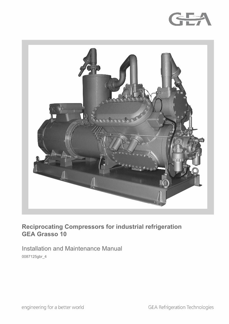
Reciprocating Compressors for industrial refrigerationGEA Grasso 10
Installation and Maintenance Manual0087125gbr_4

COPYRIGHT
All Rights reserved. No part of this publication maybe copied or published by means of printing, photo-copying, microfilm or otherwise without prior writtenconsent of Grasso.This restriction also applies to the correspondingdrawings and diagrams.
LEGAL NOTICEThis publication has been written in good faith. How-ever, Grasso cannot be held responsible, neither forany errors occurring in this publication nor for theirconsequences.
Installation and Maintenance Manual | GEA Grasso 10Reciprocating Compressors for industrial refrigeration
2 GEA Refrigeration Netherlands N.V. | 0087125gbr_4 | Created 25.04.2016
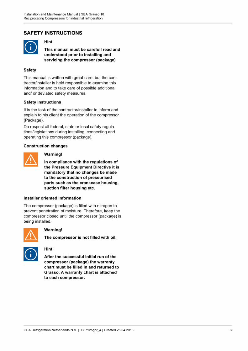
SAFETY INSTRUCTIONSHint!
This manual must be carefull read andunderstood prior to installing andservicing the compressor (package)
Safety
This manual is written with great care, but the con-tractor/installer is held responsible to examine thisinformation and to take care of possible additionaland/ or deviated safety measures.
Safety instructions
It is the task of the contractor/installer to inform andexplain to his client the operation of the compressor(Package).Do respect all federal, state or local safety regula-tions/legislations during installing, connecting andoperating this compressor (package).
Construction changes
Warning!
In compliance with the regulations ofthe Pressure Equipment Directive it ismandatory that no changes be madeto the construction of pressurisedparts such as the crankcase housing,suction filter housing etc.
Installer oriented information
The compressor (package) is filled with nitrogen toprevent penetration of moisture. Therefore, keep thecompressor closed until the compressor (package) isbeing installed.
Warning!
The compressor is not filled with oil.
Hint!
After the successful initial run of thecompressor (package) the warrantychart must be filled in and returned toGrasso. A warranty chart is attachedto each compressor.
Installation and Maintenance Manual | GEA Grasso 10Reciprocating Compressors for industrial refrigeration
GEA Refrigeration Netherlands N.V. | 0087125gbr_4 | Created 25.04.2016 3
PREFACE
General
1. All documentation can be downloaded via ourweb site.
2. Grasso’s technical manuals includes “genericparagraphs”; this means that it can occur thatnot all data as described is relevant for the cur-rent compressor series as mentioned in thismanual. (For instance, not all compressor seriesare suitable for all mentioned refrigerants or notall compressor series includes two-stage com-pressors)
Directives
Equipment is based on Pressure Equipment Direc-tive (PED 97/23/EG) regulations and according toMachine Directive (MD 2006/42/EG) regulations.
The applied standards are:NEN-EN-IEC 60204, NEN-EN-ISO 12100, NEN-EN-ISO 13857, NEN-EN 378
Installation and Maintenance Manual | GEA Grasso 10Reciprocating Compressors for industrial refrigeration
4 GEA Refrigeration Netherlands N.V. | 0087125gbr_4 | Created 25.04.2016

CYLINDER NUMBERING
Fig.1: Cylinder numbering Grasso reciprocating compressors
Legend
1, 2, 3, ... Cylinder numbers
T Top view of compressor
M Motor/Drive end of compressor
O Oil pump of compressor
Installation and Maintenance Manual | GEA Grasso 10Reciprocating Compressors for industrial refrigeration
GEA Refrigeration Netherlands N.V. | 0087125gbr_4 | Created 25.04.2016 5
Installation and Maintenance Manual | GEA Grasso 10Reciprocating Compressors for industrial refrigeration
6 GEA Refrigeration Netherlands N.V. | 0087125gbr_4 | Created 25.04.2016

GENERALINFO
Main setup data Grasso 10
Description Value Remark
Start frequency max. 6 starts per hour
Time interval between stopping and re-start-ing min. 2 minutes
Time interval between starting and re-start-ing min. 10 minutes
Time interval between capacity steps min. 3 minutes
For continuous minimum part-load (i.e. more than30 minutes) consult Grasso.
Adjust the steps between up and down loading, insuch a way that the system is running stable.
Oil level 25-75% crankcase sight glass
Min. oil temperature > 10 oC and > Pcrankcase + 15 K
Max. oil temperature Refer to oil selection table/applied typeof oil
Required oil viscosity;≥ 10 cSt during operation at location of bearings
Control oil pressure suction pressure + 8 bar
Lubricating oil pressure difference between 1.3 and 4.5 bar Settingapprox. 2.0 bar
After a mimimum of 15 minutes running time at anoil temperature of approx. 50 oC (122 oF)
Max. discharge temperature 170 °C
Min. suction pressure 0.3 bar (a)
Max. intermediate pressureMax. suction pressure
8.5 bar (a)
Pdischarge - Psuction ≤25.0 bar
Superheat>0 K for NH3, R22
>15K for R507/R404A/R134a
Oil suction filter Blue coloured filter element
Oil discharge - running in - filter Red coloured filter element
Hint!
Factory mounted; to be replacedafter max. 100 running hours by
permanent oil discharge filter ele-ment
Installation and Maintenance Manual | GEA Grasso 10Reciprocating Compressors for industrial refrigeration
GEA Refrigeration Netherlands N.V. | 0087125gbr_4 | Created 25.04.2016 7

Main setup data Grasso 10
Description Value Remark
Oil discharge - permanent - filter Grey filter element
Hint!
Supplied loose; replacement forfactory mounted running in filter
Direction of rotation of compressor driveshaft
Counterclockwise when facing shaftend
Installation and Maintenance Manual | GEA Grasso 10Reciprocating Compressors for industrial refrigeration
8 GEA Refrigeration Netherlands N.V. | 0087125gbr_4 | Created 25.04.2016

TABLE OF CONTENTS1 INSTALLATION AND PREPARATION FOR USE 11
1.1 Running-in oil filter has to be installed after an overhaul or big repair 111.2 INSTALLATION 11
1.2.1 Moving instructions and storage 111.2.2 Storage 111.2.3 Hoisting and moving instructions 121.2.4 Required free space 121.2.5 Foundation requirements 12
1.2.5.1 Concrete structure 131.2.5.2 Anchoring 131.2.5.3 Mounting the base frame on a concrete block 151.2.5.4 Mounting bare compressor on a concrete block 15
1.2.6 Connecting to refrigerating system pipework 161.2.7 Connecting the power supply 161.2.8 Earthing connections 161.2.9 Separately delivered components 16
1.3 PREPARATIONS FOR USE 171.3.1 Leak test of compressor and system 171.3.2 EVACUATION/DRYING THE REFRIGERATING SYSTEM 171.3.3 Initial oil charge 17
1.3.3.1 Initial oil charge 171.3.4 Initial refrigerant charge 181.3.5 Adjustment of instruments and safety devices 18
1.3.5.1 CONTROL DEVICES 181.3.5.2 Refrigerants R717 and halocarbons 181.3.5.3 Re-adjustment of oil pressure regulator 18
1.3.6 Checking direction of rotation of motor shaft 191.3.7 Installing the drive guards (if present) 191.3.8 Initial oil warm up 191.3.9 Initial start-up 19
1.3.9.1 Limitations of part load operation and start-up 201.3.9.2 WIRING LOGIC NORMALLY OPEN UNLOADED START SOLENOID 201.3.9.3 Frequency controlled compressor 201.3.9.4 Pre-start check list 20
1.3.10 Starting and stopping procedures 201.3.10.1 First start 211.3.10.2 Restart 211.3.10.3 Restart after a short standstill period of time (less than 1 month) 211.3.10.4 Restart after a long standstill period of time 221.3.10.5 Stopping the compressor 22
2 INSPECTION AND TROUBLE SHOOTING 232.1 Periodical inspection 232.2 Survey of periodical inspections 23
2.2.1 Check list periodical inspection 242.3 STEPS FOR LONGER SHUT-DOWN PERIODS (> 6 months) 242.4 LUBRICATION DATA 25
2.4.1 Topping up oil with compressor operating 252.5 EVACUATION, LEAK TESTING AND START-UP OF THE COMPRESSOR/PACKAGE 25
2.5.1 EVACUATION OF REFRIGERANT BEFORE SERVICING 252.5.2 LEAK-TIGHTNESS AFTER SERVICING 252.5.3 EVACUATION AFTER SERVICING 262.5.4 START-UP AFTER SERVICING 26
2.6 DRAINING AND CHANGE OF OIL 262.6.1 DRAINING OIL REVERVOIR FOR MARINE USE (Optional) 26
2.7 REPLACEMENT OF OIL FILTERS 262.7.1 Oil discharge filter 262.7.2 Oil suction filter (Pos. B) 27
2.8 REPLACEMENT OF SUCTION GAS FILTER(S) 272.9 DISMANTLING, INSPECTION AND RE-ASSEMBLY OF SUCTION AND DISCHARGE VALVES 272.10 COMPRESSOR PURGING 27
Installation and Maintenance Manual | GEA Grasso 10Reciprocating Compressors for industrial refrigeration
GEA Refrigeration Netherlands N.V. | 0087125gbr_4 | Created 25.04.2016 9
2.11 TROUBLESHOOTING TABLE GRASSO RECIPROCATING COMPRESSORS 283 MAINTENANCE 31
3.1 Post start-up maintenance 313.2 First maintenance 313.3 SMS FACTOR 313.4 Legend 32
3.4.1 Grasso 10 333.4.2 Checklist 36
Installation and Maintenance Manual | GEA Grasso 10Reciprocating Compressors for industrial refrigeration
10 GEA Refrigeration Netherlands N.V. | 0087125gbr_4 | Created 25.04.2016

1 INSTALLATION AND PREPARATION FOR USE
1.1 Running-in oil filter has to be instal-led after an overhaul or big repair
Hint!
This is why and when the running inoil filters are required:
Warning!
A running in oil filter has always to beinstalled after an overhaul or big repairfor the 1st 100 hours of operation!The oil and oil oil filters have to bereplaced by new oil and filters.Due to running-in wear of liners andpiston rings, it's normal that the oilbecomes grey during the 1st 100 oper-ating hours.After 100 operating hours, the oilcould slightly become clear again.
1.2 INSTALLATION
Warning!
The compressor is not charged withoil, therefore, DO NOT start the com-pressor before it has been installedand prepared according to Grasso’sinstructions.
This section contains instructions for the properinstallation of a Grasso compressor (package).Before the compressor (package) is ready for the ini-tial start up, the installation instructions in the follow-ing paragraphs must be followed:
1. The Compressor (Package) should be levelledand securely anchored to the foundation.
2. All piping should be completed.
3. The system and the compressor are to be pres-sure tested for leaks (see. Section 1.3.1,Page 17)
4. The system should be evacuated to remove airand moisture.
5. The electric wiring should be completed as perwiring diagrams. Do not energise the main powercontrol cabinet until oil is added and the directionof rotation has been checked.
6. The compressor is to be filled with the correcttype and amount of lubricating oil and has to bepre-lubricated (Refer ) before the first start.
7. ‘Open compressors’ only;
7.1 Open compressors;The drive system should be installed.
7.2 (Semi) hermitic compressors;Mark R-S-T-N power supply in the terminalbox of the motor.
8. The system should be charged with the correctamount of refrigerant.
9. The oil should be warmed up above minimumstart up oil temperature (see "Product Informa-tion").
10. The control cabinet should be energised tocheck the package controls.
Hint!
Do not forget to charge the oil separa-tor (if present) initially with oil, to thelevel of the float assembly
1.2.1 Moving instructions and storage
For loose component or compressor packageweights, refer either to the relevant component typeplate or package lay-out or to the suppliers docu-ment. For bare compressor weights, see "ProductInformation".
Caution!
Every precaution must be taken whilemoving the package to its final loca-tion. Pushing, pulling or climbing onany package component or piping, caneasily create damage.
1.2.2 Storage
Installation and Maintenance Manual | GEA Grasso 10Reciprocating Compressors for industrial refrigeration
GEA Refrigeration Netherlands N.V. | 0087125gbr_4 | Created 25.04.2016 11

The compressor (package) is filled with dry nitrogen.Keep the system closed until the package is instal-led. If the compressor (package) is stored, it shouldbe kept at all times in a dry location to prevent corro-sion damage. If the compressor (package) is to bestored for a prolonged period of time, it should bechecked weekly to ensure that the holding charge ofdry nitrogen remains above atmospheric pressure.
1.2.3 Hoisting and moving instructions
Fig.2: Hoisting a compressor package
Packaged base frame:
The only places that can be used for safe hoisting ofthe package are the four hoisting eyes on the steelbase frame as shown in the above figure. Prior tohoisting a compressor package with a V-belt drivearrangement, the factory mounted drive guard has tobe removed. Attach spreader bars to the slings so asto prevent damage to piping and components.
Warning!
DO NOT use the compressor or motoror oil separator hoisting eyes to movethe package! These hoisting eyes areintended for lifting loose componentsonly and not for the entire package!
Bare compressor or loose components:
Determine the dead weight of the particular compo-nent (see "Product Information (ED)"), prior to mov-ing a bare compressor or loose component. Use thehoisting eyes only, DO NOT sling from other com-pressor parts (see Figure 3, Page 12).
Fig.3: Hoisting angle
Moving by fork-lift truck
The bare compressor or package can be transportedwith a fork-lift truck with the forks spread as much aspossible between the skids. To simplify moving, the2 wooden transport beams must still be mountedunderneath the base frame and stored in this way,until the package is positioned above its approximatelocation.
1.2.4 Required free space
For easy operating, servicing and maintenanceaccess, the compressor (package) should be instal-led with sufficient free space around it.
Hint!
Refer to “Product Information“ forminimum requirements.
1.2.5 Foundation requirements
Hint!
Compressor (package) has to bemounted on a concreted block. Onrequest, Grasso can calculate theexact dimensions of the concreteblock, based on the compressor sizeand operating conditions.
Installation and Maintenance Manual | GEA Grasso 10Reciprocating Compressors for industrial refrigeration
12 GEA Refrigeration Netherlands N.V. | 0087125gbr_4 | Created 25.04.2016
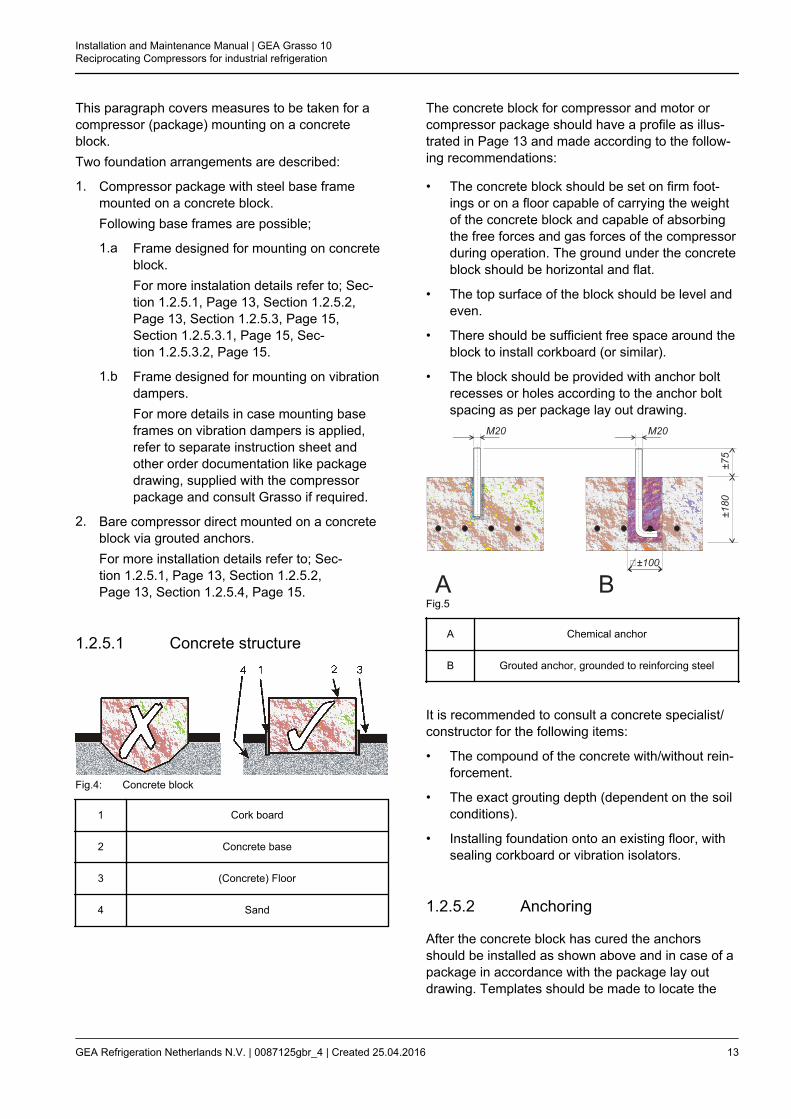
This paragraph covers measures to be taken for acompressor (package) mounting on a concreteblock.Two foundation arrangements are described:
1. Compressor package with steel base framemounted on a concrete block.Following base frames are possible;
1.a Frame designed for mounting on concreteblock.For more instalation details refer to; Sec-tion 1.2.5.1, Page 13, Section 1.2.5.2,Page 13, Section 1.2.5.3, Page 15,Section 1.2.5.3.1, Page 15, Sec-tion 1.2.5.3.2, Page 15.
1.b Frame designed for mounting on vibrationdampers.For more details in case mounting baseframes on vibration dampers is applied,refer to separate instruction sheet andother order documentation like packagedrawing, supplied with the compressorpackage and consult Grasso if required.
2. Bare compressor direct mounted on a concreteblock via grouted anchors.For more installation details refer to; Sec-tion 1.2.5.1, Page 13, Section 1.2.5.2,Page 13, Section 1.2.5.4, Page 15.
1.2.5.1 Concrete structure
Fig.4: Concrete block
1 Cork board
2 Concrete base
3 (Concrete) Floor
4 Sand
The concrete block for compressor and motor orcompressor package should have a profile as illus-trated in Page 13 and made according to the follow-ing recommendations:
• The concrete block should be set on firm foot-ings or on a floor capable of carrying the weightof the concrete block and capable of absorbingthe free forces and gas forces of the compressorduring operation. The ground under the concreteblock should be horizontal and flat.
• The top surface of the block should be level andeven.
• There should be sufficient free space around theblock to install corkboard (or similar).
• The block should be provided with anchor boltrecesses or holes according to the anchor boltspacing as per package lay out drawing.
Fig.5
A Chemical anchor
B Grouted anchor, grounded to reinforcing steel
It is recommended to consult a concrete specialist/constructor for the following items:
• The compound of the concrete with/without rein-forcement.
• The exact grouting depth (dependent on the soilconditions).
• Installing foundation onto an existing floor, withsealing corkboard or vibration isolators.
1.2.5.2 Anchoring
After the concrete block has cured the anchorsshould be installed as shown above and in case of apackage in accordance with the package lay outdrawing. Templates should be made to locate the
Installation and Maintenance Manual | GEA Grasso 10Reciprocating Compressors for industrial refrigeration
GEA Refrigeration Netherlands N.V. | 0087125gbr_4 | Created 25.04.2016 13
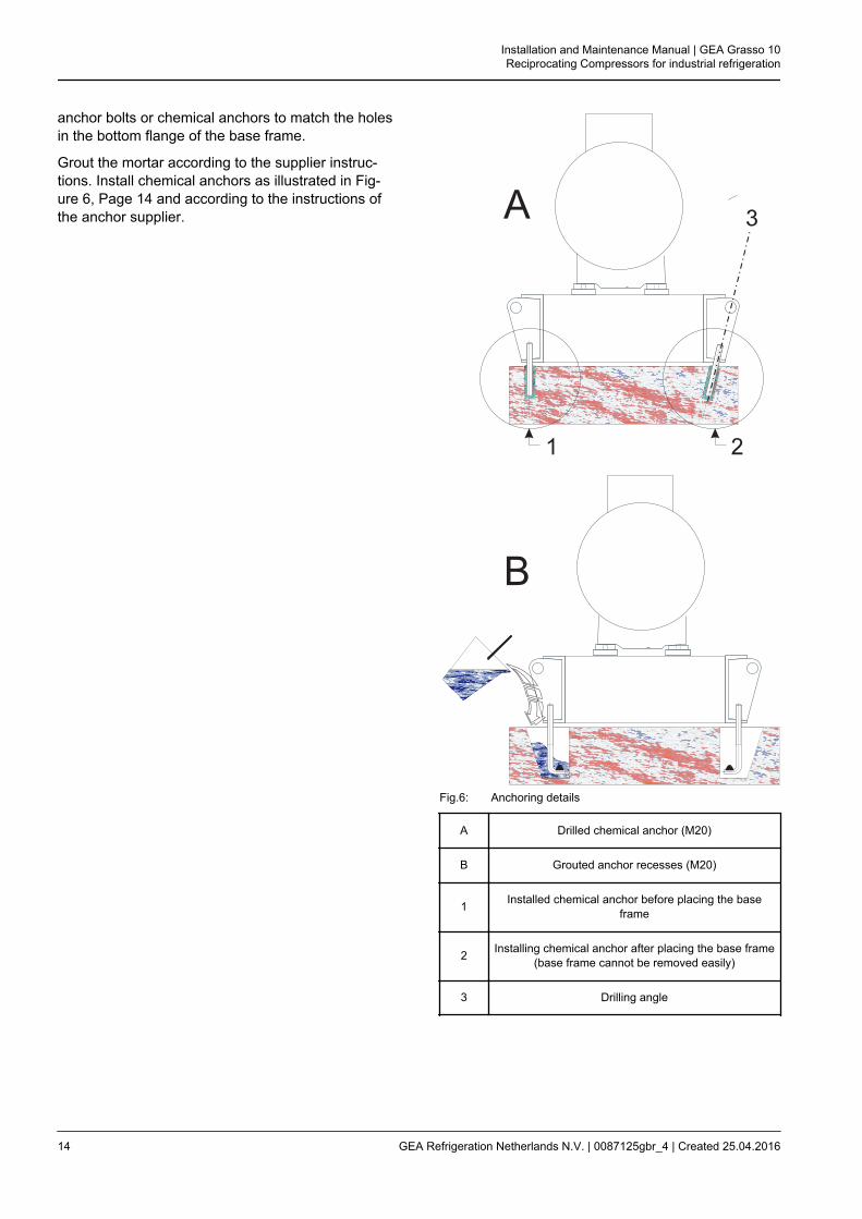
anchor bolts or chemical anchors to match the holesin the bottom flange of the base frame.
Grout the mortar according to the supplier instruc-tions. Install chemical anchors as illustrated in Fig-ure 6, Page 14 and according to the instructions ofthe anchor supplier.
Fig.6: Anchoring details
A Drilled chemical anchor (M20)
B Grouted anchor recesses (M20)
1 Installed chemical anchor before placing the baseframe
2 Installing chemical anchor after placing the base frame(base frame cannot be removed easily)
3 Drilling angle
Installation and Maintenance Manual | GEA Grasso 10Reciprocating Compressors for industrial refrigeration
14 GEA Refrigeration Netherlands N.V. | 0087125gbr_4 | Created 25.04.2016

1.2.5.3 Mounting the base frame on aconcrete block
General
After the space between base frame and concretebase has been filled-up with a filling grout, the pack-age base frame must be secured tightly to the foun-dation block or floor.
1.2.5.3.1 Levelling the base frame
Fig.7: Grouting details
1 Self-levelling grout
2 Adjusting bolts (4x)
3 Washer
4 Temporary barrier strip around and inside frame
5 Complete cured concrete block
6 Grout layer
After the anchor filling mortar has completely curedthe frame should be levelled with a space betweenblock and lower frame flange of 3 - 5 mm*. Thisspace is necessary for levelling using the base frameadjusting bolts with metal washers (supplied sepa-rately). The base frame should be levelled on eachframe side. Adjust the frame on each adjusting placeuntil all frame sides are horizontal.
This space largely depends on the sort of grout ormortar used. Determine this space according to theinstructions of the grout or mortar supplier.
1.2.5.3.2 Finishing with a self-level-ling grout
After levelling has been completed the adjusting boltends must be greased to avoid bonding to the self-levelling grout. The space between concrete blockand frame must be completely filled with the self-lev-elling grout to ensure that the complete bottom sur-face of the base frame will be supported. Therefore,it is not allowed to use shims between concrete baseand base frame.
Grouting must be carried out in accordance with theinstructions provided by the grouting supplier. Aftercomplete de-aeration of the grouted layer, secure thebase frame by tightening the anchor bolt nuts andremove all adjusting bolts. At this stage the drivesystem can be installed. These (accessories) instal-lation instructions can be found in the order manual.
1.2.5.4 Mounting bare compressor ona concrete block
If base frame is not applied the approximately thesame procedure of levelling the base frame has tobe applied for the bare shaft compressor (refer Sec-tion 1.2.5.3, Page 15).The mounting surfaces of the compressor feet mustbe level without any deviation and projecting at least10 mm above the concrete base.
Installation and Maintenance Manual | GEA Grasso 10Reciprocating Compressors for industrial refrigeration
GEA Refrigeration Netherlands N.V. | 0087125gbr_4 | Created 25.04.2016 15

Fig.8: Grouting details of bare compressor on concrete block
Legend
1 Self leveling grout
2 Foundation anchor
3 Layer of self leveling grout (10 - 15 mm)
4 Temporary barrier strip aroud each compressorfoot
5 Complete cured concrete block
CF Compressor foot
WLWidth of grout layer(WL-WC > 40 mm)
WCWidth of compressor foot
(WL-WC > 40 mm)
1.2.6 Connecting to refrigerating sys-tem pipework
Warning!
DO NOT ground through the compres-sor when arc welding
After the compressor (package) has been levelledand secured to the foundation, the system pipingmay be connected. The suction line(s) and dischargeline(s) should be installed and supported such thatthere is no load exerted on the compressor. The sizeand location of the suction and discharge connec-tions, can be found in the "Product Information" (barecompressor) and in case of a package, the packagelay out drawing.
Hint!
If an oil rectifier system is applied inthe refrigeration system, the oil returnline must be connected to the oilreturn connection (see "Product Infor-mation").
Suspension of system pipework
To eliminate vibration transmission to the systempiping, the following is recommended:
• Install all piping free of tension.
• Secure the piping by clips or brackets in twodirections.
• Install (stop) valves, piping and accessoriessuch, that there is no load exerted on the com-pressor.
1.2.7 Connecting the power supply
Information about further electrical connections to bemade (e.g. crankcase heater, drive motor startingequipment, thermal protection of drive motor, auto-matic start/ stop and other external electrical devi-ces) can be found in the plant manual (not suppliedby Grasso).
1.2.8 Earthing connections
Grasso compressors and packages are equippedwith litz-wires and earth connecting points.To avoid leakage current flowing through the compo-nents, disconnect all litz-wires when arc-welding.After all installation functions are completed, recon-nect the litz-wires and ground the package to earth.
1.2.9 Separately delivered components
Hint!
Check whether the sets/parts/compo-nents belonging to this compressorare supplied loose! (Refer to orderconfirmation)
Mount these separately delivered sets, componentsand/or parts, according to the instructions as sup-plied with this compressor (package).
Installation and Maintenance Manual | GEA Grasso 10Reciprocating Compressors for industrial refrigeration
16 GEA Refrigeration Netherlands N.V. | 0087125gbr_4 | Created 25.04.2016

1.3 PREPARATIONS FOR USE
After the Compressor (Package) has been installed(excluding final connection of drive device), the fol-lowing actions should be followed in the order given:
1.3.1 Leak test of compressor and sys-tem
The compressor (package) has been pressure testedprior to leaving the factory. In case an additional leaktest is required, this test is should be carried out withdry nitrogen.
Hint!
DO NOT add oil to the compressorprior to pressure testing
A system leak test should be carried out over 24hours to ensure that the system is tightly sealed.Record during the pressure test, the pressure, ambi-ent temperature and outside temperature. During theinitial 6 hours a pressure drop of 2% is permissable.With respect to temperature variations, no furtherpressure loss should be detected in the remaining 18hours.
1.3.2 EVACUATION/DRYING THEREFRIGERATING SYSTEM
For evacuation of compressor only, refer to Sec-tion 2.5, Page 25
Procedure to evacuate and to dry a system:
i. STATUS: System is filled with nitrogen and nooil has been added (oil prevents any trappedmoisture from boiling off).
ii. Verify that all valves in that part of the systemto be evacuated are opened (refer also to theplant manual).
iii. Connect vacuum pump to the evacuation/purg-ing valve(s) of the compressor (for location ofthese valves refer to the "Product Information"or to a connection as mentioned in the plantmanual and evacuate the system to approx. 6mBar.
iv. Break vacuum by charging dry nitrogen into thesystem.
v. Repeat step iii, "Connect vacuum pump ...".
vi. Wait approx. 24 hours.
vii. If pressure has increased (system still containsmoisture), repeat steps iv, and vi. Otherwise,continue with the "Initial oil charge" procedure.
1.3.3 Initial oil charge
Warning!
Oil charging via the suction line of thecompressor is not allowed.Used or filtered oil should NEVER BEadded to a compressor under any cir-cumstance.Use only new oil as selected from theGrasso oil table. (Refer )
Procedure:
i. STATUS: System is dried and still evacuated.
ii. Charge the oil separator (if present) initiallywith oil .
iii. Close suction and discharge stop valves ofcompressor and oil return line of oil separator(if present).
iv. Charge the compressor crankcase with oil viathe oil charge valve.
Warning!
Pre-lubrication just before the firststart is obligatory.
Hint!
Filling of the afore mentioned compo-nents is also possible by means of aseparate oil filling pump via the oilcharge valves mounted onto the oilpump housing.
1.3.3.1 Initial oil charge
Installation and Maintenance Manual | GEA Grasso 10Reciprocating Compressors for industrial refrigeration
GEA Refrigeration Netherlands N.V. | 0087125gbr_4 | Created 25.04.2016 17
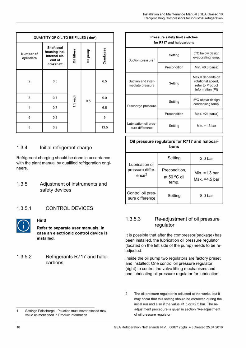
QUANTITY OF OIL TO BE FILLED ( dm3)
Number ofcylinders
Shaft sealhousing incl.internal cir-
cuit ofcrnkshaft O
il fil
ters
Oil
pum
p
Cra
nkca
se
2 0.6
1.5
each
0.5
6.5
3 0.7 9.0
4 0.7 6.5
6 0.8 9
8 0.9 13.5
1.3.4 Initial refrigerant charge
Refrigerant charging should be done in accordancewith the plant manual by qualified refrigeration engi-neers.
1.3.5 Adjustment of instruments andsafety devices
1.3.5.1 CONTROL DEVICES
Hint!
Refer to separate user manuals, incase an electrionic control device isinstalled.
1.3.5.2 Refrigerants R717 and halo-carbons
1 Settings Pdischarge - Psuction must never exceed max.value as mentioned in Product Information
Pressure safety limit switchesfor R717 and halocarbons
Suction pressure1Setting 5oC below design
evaporating temp.
Precondition Min. =0.3 bar(a)
Suction and inter-mediate pressure Setting
Max.= depends onrotational speed,refer to ProductInformation (PI)
Discharge pressureSetting 5oC above design
condensing temp.
Precondition Max. =24 bar(a)
Lubrication oil pres-sure difference Setting Min. =1.3 bar
Oil pressure regulators for R717 and halocar-bons
Lubrication oilpressure differ-
ence2
Setting 2.0 bar
Precondition,
at 50 oC oiltemp.
Min. =1.3 barMax. =4.5 bar
Control oil pres-sure difference Setting 8.0 bar
1.3.5.3 Re-adjustment of oil pressureregulator
It is possible that after the compressor(package) hasbeen installed, the lubrication oil pressure regulator(located on the left side of the pump) needs to be re-adjusted.
Inside the oil pump two regulators are factory presetand installed; One control oil pressure regulator(right) to control the valve lifting mechanisms andone lubricating oil pressure regulator for lubrication.
2 The oil pressure regulator is adjusted at the works, but itmay occur that this setting should be corrected during theinitial run and also if the value <1.5 or >2.5 bar. The re-adjustment procedure is given in section “Re-adjustmentof oil pressure regulator.
Installation and Maintenance Manual | GEA Grasso 10Reciprocating Compressors for industrial refrigeration
18 GEA Refrigeration Netherlands N.V. | 0087125gbr_4 | Created 25.04.2016
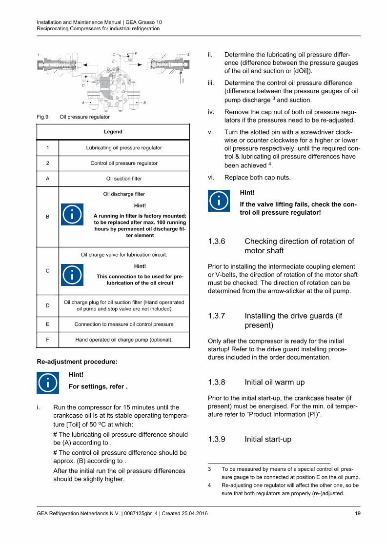
Fig.9: Oil pressure regulator
Legend
1 Lubricating oil pressure regulator
2 Control oil pressure regulator
A Oil suction filter
B
Oil discharge filter
Hint!
A running in filter is factory mounted;to be replaced after max. 100 runninghours by permanent oil discharge fil-
ter element
C
Oil charge valve for lubrication circuit.
Hint!
This connection to be used for pre-lubrication of the oil circuit
D Oil charge plug for oil suction filter (Hand operaratedoil pump and stop valve are not included)
E Connection to measure oil control pressure
F Hand operated oil charge pump (optional).
Re-adjustment procedure:
Hint!
For settings, refer .
i. Run the compressor for 15 minutes until thecrankcase oil is at its stable operating tempera-ture [Toil] of 50 oC at which:# The lubricating oil pressure difference shouldbe (A) according to .# The control oil pressure difference should beapprox. (B) according to .After the initial run the oil pressure differencesshould be slightly higher.
ii. Determine the lubricating oil pressure differ-ence (difference between the pressure gaugesof the oil and suction or [dOil]).
iii. Determine the control oil pressure difference(difference between the pressure gauges of oilpump discharge 3 and suction.
iv. Remove the cap nut of both oil pressure regu-lators if the pressures need to be re-adjusted.
v. Turn the slotted pin with a screwdriver clock-wise or counter clockwise for a higher or loweroil pressure respectively, until the required con-trol & lubricating oil pressure differences havebeen achieved 4.
vi. Replace both cap nuts.
Hint!
If the valve lifting fails, check the con-trol oil pressure regulator!
1.3.6 Checking direction of rotation ofmotor shaft
Prior to installing the intermediate coupling elementor V-belts, the direction of rotation of the motor shaftmust be checked. The direction of rotation can bedetermined from the arrow-sticker at the oil pump.
1.3.7 Installing the drive guards (ifpresent)
Only after the compressor is ready for the initialstartup! Refer to the drive guard installing proce-dures included in the order documentation.
1.3.8 Initial oil warm up
Prior to the initial start-up, the crankcase heater (ifpresent) must be energised. For the min. oil temper-ature refer to “Product Information (PI)“.
1.3.9 Initial start-up
3 To be measured by means of a special control oil pres-sure gauge to be connected at position E on the oil pump.
4 Re-adjusting one regulator will affect the other one, so besure that both regulators are properly (re-)adjusted.
Installation and Maintenance Manual | GEA Grasso 10Reciprocating Compressors for industrial refrigeration
GEA Refrigeration Netherlands N.V. | 0087125gbr_4 | Created 25.04.2016 19
1.3.9.1 Limitations of part load opera-tion and start-up
The capacity control serves to adapt the compressorcapacity at any moment as closely as possible to therefrigerating capacity. In order to adjust the capacity,a number of cylinders can be put in or out of actioneither individually or collectively by means of sole-noid valves.
Warning!
Due to start-up limitations and to limi-tations of part load operation it may bethat not all available part load stepsare allowed under certain conditions.Use of incorrect control steps candamage compressor and/or compo-nents.
For a detailed description about start-up and partload limitations refer to the software program “Com-sel”.
1.3.9.2 WIRING LOGIC NORMALLYOPEN UNLOADED STARTSOLENOID
1. If compessor is NOT running then NO-solenoidis not energised.
2. Energise the NO-solenoid 10 - 20 secondsbefore starting.
3. If compressor starts then NO-solenoid is ener-gised and de-energised by means of an auxiliarytime relay.
4. Ensure that the NO-solenoid valve is not de-energised until the minimum allowed compressorspeed has been achieved and the specified lubri-cation oil pressure has been established.
5. Energise the NO-solenoid 5 seconds beforestopping until the compressor is stopped com-pletely.
1.3.9.3 Frequency controlled com-pressor
Hint!
In case of frequency controlled com-pressors, a separate instruction00.87.041 is required. If you don’t havethis instruction consult Grasso.
1.3.9.4 Pre-start check list
The following Paragraph covers only the initial startof the compressor and not the complete refrigerationplant.
Be sure that all necessary system valves are openand that the refrigeration system is ready for start up.Use the following check to guarantee that no items ofimportance regarding the compressor (package)have been overlooked.
i. System is charged with refrigerant.
ii. Settings of safety limit switches are adjustedproperly.
iii. Direction of rotation of compressor crankshaftis correct.
iv. Check capacity control: Set the electricalcapacity control to the position of the lowestpart load step.
v. Oil level established in sight glass.
vi. Stop valves to the pressure gauges are open.
vii. Suction stop valve is closed (in case the evap-orating temperature is much higher than thedesign evaporating temperature) and the dis-charge stop valve is open and in case of two-stage compressors that the stop valves in theintermediate circuit lines are open.
viii. Stop valve in the oil return line of the oil sepa-rator (if present) is closed.
When all items are verified, the compressor (pack-age) is ready for the start-up.
1.3.10 Starting and stopping procedures
Installation and Maintenance Manual | GEA Grasso 10Reciprocating Compressors for industrial refrigeration
20 GEA Refrigeration Netherlands N.V. | 0087125gbr_4 | Created 25.04.2016

Hint!
For all limitations refer to "Main setupdata"-overview! The values in the mainsetup data tables, overrules the valuesas mentioned in the text.
When starting the compressor a distinction should bemade between:
1.3.10.1 First start
i. Notice "Pre-start check list", also consult theplant manual and verify the following items:
– Check the oil temperature (refer to the"Product Information").
– Check crankcase oil level (refer to Sec-tion 2.4.1, Page 25).
ii. Start the compressor and check whether the oilpressure increases.
Hint!
The time interval between stoppingand starting should be at least 2minutes and between starting and re-starting 10 minutes.
iii. Slowly open suction stop valve and watch suc-tion pressure, which may not exceed the max.value.
Hint!
Refrigerant liquid hammer, will dam-age the compressor; Superheat isalways necessary! Refer to generallimits of operation to determine themimimum superheat for current refrig-erant!
iv. In case of electrically operated capacity con-trol:
iv.a Single-stage compressors: One or morecylinders will be energized.
iv.b Two-stage compressors: 3 - 5 minutesafter starting and only when HP-cylin-der(s) is (are) in operation, the LP cylin-ders can be energised.
Hint!
In the case of decreasing capacity fortwo stage compressors, it is notallowed to cut out all LP-cylinders.
v. Watch maximum allowable motor current (referto motor type plate).
vi. Watch discharge temperatures LP and HP,max. intermediate pressure and max. allowablemotor current (refer to motor type plate).
vii. Adjust pressure gauge stop valves, in order toavoid vibration of the pointers.
viii. Open the stop valve in the oil return line fromthe oil separator (if present).
ix. Open compressors only; After 50 hours ofoperation retighten the coupling bolts or checkand/or correct the tension of the V-belts andretighten the foundation bolts (with due respectto the torque settings given by the supplier ofthe fasteners!).
1.3.10.2 Restart
Hint!
For the time interval between stoppingand starting refer to "Main setup data"-overview.
Proceed to the complete starting procedure like “Firststart“
1.3.10.3 Restart after a short standstillperiod of time (less than 1month)
• Refer to Section 1.3.10.2, Page 21.
Installation and Maintenance Manual | GEA Grasso 10Reciprocating Compressors for industrial refrigeration
GEA Refrigeration Netherlands N.V. | 0087125gbr_4 | Created 25.04.2016 21

1.3.10.4 Restart after a long standstillperiod of time
After a seasonal standstill (1 till 6 months) ormaintenance operations;
Warning!
After a standstill period of time morethan 1 month, pre-lubrication justbefore starting is always obligatory.Refer
• Check settings of control and safety equipment.
• Proceed to the complete starting procedure.
Warning!
Restarting compressor after a stand-still period of time more than 6months, consult your supplier. It isrecommended to proceed with the ini-tial start up procedure.
1.3.10.5 Stopping the compressor
The compressor can be stopped at any moment,however, consult the supplier if further actions arerequired.
Installation and Maintenance Manual | GEA Grasso 10Reciprocating Compressors for industrial refrigeration
22 GEA Refrigeration Netherlands N.V. | 0087125gbr_4 | Created 25.04.2016

2 INSPECTION AND TROUBLE SHOOTING
2.1 Periodical inspection
These inspections should be made during the normalshut-down periods as much as possible, so the com-pressor is always ready to operate when required. If,at that time, the number of running hours slightly dif-fers from the scheduled period below, the inspectionshould nevertheless be carried out.
In this way it will not be necessary to stop the com-pressor at inconvenient times.The frequency of inspections is dependent on thetype of installation, operating conditions and localregulations. In the case of automatically controlledplants, the periodical inspection are particularlyimportant. The table below sums up all the points onthe compressor that have to be inspected or main-tained along with inspection and maintenance fre-quencies.
2.2 Survey of periodical inspections
Apart from the check points in the table below, thesound produced by the compressor also provides anindication of its mechanical condition. If abnormalsounds are audible, their cause should be traced andremoved immediately in order to prevent seriousbreakdowns.
Installation and Maintenance Manual | GEA Grasso 10Reciprocating Compressors for industrial refrigeration
GEA Refrigeration Netherlands N.V. | 0087125gbr_4 | Created 25.04.2016 23
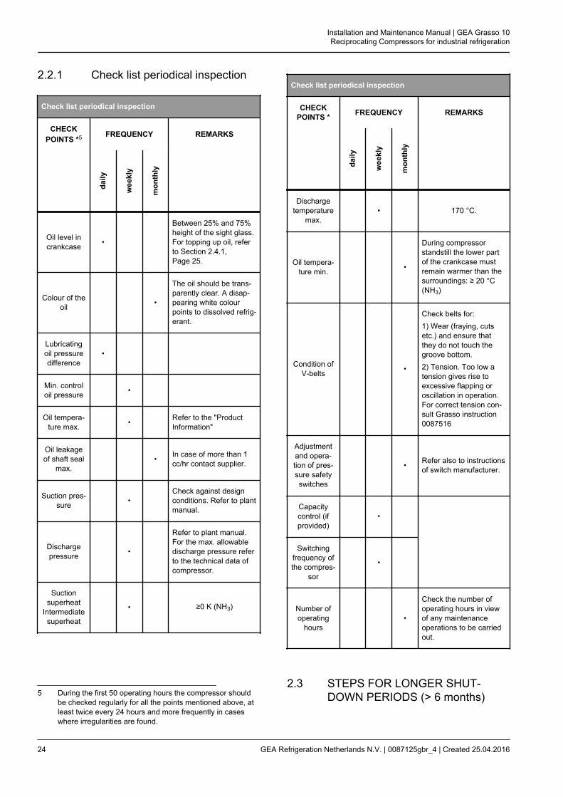
2.2.1 Check list periodical inspection
Check list periodical inspection
CHECKPOINTS *5 FREQUENCY REMARKS
daily
wee
kly
mon
thly
Oil level incrankcase •
Between 25% and 75%height of the sight glass.For topping up oil, referto Section 2.4.1,Page 25.
Colour of theoil •
The oil should be trans-parently clear. A disap-pearing white colourpoints to dissolved refrig-erant.
Lubricatingoil pressuredifference
•
Min. controloil pressure •
Oil tempera-ture max. • Refer to the "Product
Information"
Oil leakageof shaft seal
max. • In case of more than 1
cc/hr contact supplier.
Suction pres-sure •
Check against designconditions. Refer to plantmanual.
Dischargepressure •
Refer to plant manual.For the max. allowabledischarge pressure referto the technical data ofcompressor.
Suctionsuperheat
Intermediatesuperheat
• ≥0 K (NH3)
5 During the first 50 operating hours the compressor shouldbe checked regularly for all the points mentioned above, atleast twice every 24 hours and more frequently in caseswhere irregularities are found.
Check list periodical inspection
CHECKPOINTS * FREQUENCY REMARKS
daily
wee
kly
mon
thly
Dischargetemperature
max. • 170 °C.
Oil tempera-ture min. •
During compressorstandstill the lower partof the crankcase mustremain warmer than thesurroundings: ≥ 20 °C(NH3)
Condition ofV-belts •
Check belts for:1) Wear (fraying, cutsetc.) and ensure thatthey do not touch thegroove bottom.2) Tension. Too low atension gives rise toexcessive flapping oroscillation in operation.For correct tension con-sult Grasso instruction0087516
Adjustmentand opera-tion of pres-sure safetyswitches
• Refer also to instructionsof switch manufacturer.
Capacitycontrol (ifprovided)
•
Switching
frequency ofthe compres-
sor
•
Number ofoperating
hours •
Check the number ofoperating hours in viewof any maintenanceoperations to be carriedout.
2.3 STEPS FOR LONGER SHUT-DOWN PERIODS (> 6 months)
Installation and Maintenance Manual | GEA Grasso 10Reciprocating Compressors for industrial refrigeration
24 GEA Refrigeration Netherlands N.V. | 0087125gbr_4 | Created 25.04.2016
To shut down a compressor for long term periods,proceed as follows:
i. Tightly shut both the suction and dischargestop valves and the stop valve of the oil returnline (if present).
ii. Disconnect the power source from the com-pressor drive motor and the electrical controlcabinet.
iii. Place a moisture absorbing compound (eg adessicant such as silica gel) inside the controlcabinet.
iv. Place warning tags on the electric system andall closed stop valves.
Prior to starting up after a shut down, change the oiland exchange the oil filters. Determine the startingand stopping procedure from prior to start the com-pressor.
2.4 LUBRICATION DATA
Determine max Toil and set this value in the safetydevice.Change the oil as soon as an oil analysis indicatescontaminated oil.
Warning!
It is expressly pointed out that it is notpermitted to mix different types of oil.If another type of oil is used, firstremove all the stale oil in the filters, oilpump, crankcase, shaft seal, oil sepa-rator and oil drains of the installation.
2.4.1 Topping up oil with compressoroperating
Hint!
Use Grasso’s hand-operated oil pump,part. no. 18.13.121
Topping up oil is permitted during compressor opera-tion.
Be sure that this oil is the same as in the plant (referto Section 2.4, Page 25).
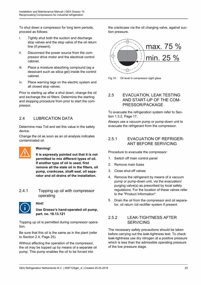
Without affecting the operation of the compressor,the oil may be topped up by means of a separate oilpump. This pump enables the oil to be forced into
the crankcase via the oil charging valve, against suc-tion pressure.
Fig.10: Oil level in compressor sight glass
2.5 EVACUATION, LEAK TESTINGAND START-UP OF THE COM-PRESSOR/PACKAGE
To evacuate the refrigeration system refer to Sec-tion 1.3.2, Page 17,Always use a vacuum pump or pump-down unit toevacuate the refrigerant from the compressor.
2.5.1 EVACUATION OF REFRIGER-ANT BEFORE SERVICING
Procedure to evacuate the compressor:
1. Switch off main control panel
2. Remove main fuses
3. Close shut-off valves
4. Remove the refrigerant by means of a vacuumpump or pump-down unit, via the evacuation/purging valve(s) as prescribed by local safetyregulations. For the location of these valves referto the "Product Information".
5. Drain the oil from the compressor and oil separa-tor, oil return /oil rectifier system if present.
2.5.2 LEAK-TIGHTNESS AFTERSERVICING
The necessary safety precautions should be takenbefore carrying out the leak-tightness test. To checkleak-tightness use dry nitrogen at a positive pressurewhich is less than the admissible operating pressureof the low pressure stage.
Installation and Maintenance Manual | GEA Grasso 10Reciprocating Compressors for industrial refrigeration
GEA Refrigeration Netherlands N.V. | 0087125gbr_4 | Created 25.04.2016 25

2.5.3 EVACUATION AFTER SERVIC-ING
After the pressure test has been completed, thecompressor (package) must be evacuated andundergo a vacuum test. Evacuation is used toremove air and moisture from the compressor (pack-age)
2.5.4 START-UP AFTER SERVICING
1. STATUS: Compressor (package) is dried andstill evacuated.
2. Charge the oil separator, if present, with oil.See the appropriate Product Information for thecorrect quantity.
3. Charge the compressor crankcase with oil viathe oil charge valve until the minimum level isseen at the sight glass at the level as indicated inIMM.It is mandatory to pre-lubricate the oil circuit byadding the final quantity of oil via the chargevalve mounted onto the oil pump by means of aseparate oil filling pump. The required oil level isindicated in the IMM.
4. Re-install all accessories such as coupling, V-belt guard etc.
5. Open the shut-off valves.
6. Check the start-stop procedure.
7. Check all safeties and controls.
8. Re-install the main fuses.
9. Start up the compressor.
10. Check running condition.
Note:The job isn't finished until the paper work is done!Complete the service report, e.g. Grasso report00.89.062.
2.6 DRAINING AND CHANGE OF OIL
To top up oil see Section 2.4.1, Page 25, Oil chang-ing procedure:
i. Evacuate the compressor (refer to Section 2.5,Page 25).
ii. Drain the oil via the oil charging/drain valve.Remove the cover of one or more serviceopenings on the compressor side.
iii. Clean the inside of the crankcase with a non-fibrous cloth (do not use cotton waste!).
iv. Replace the service cover(s) with a new seal.
v. Charge crankcase with clean oil in accordancewith the procedure.
2.6.1 DRAINING OIL REVERVOIRFOR MARINE USE (Optional)
Hint!
In case an oil reservoir for marine useis applied, this oil reservoir has also tobe drained via the oil drain plug of theoil reservoir.
2.7 REPLACEMENT OF OIL FILTERS
Hint!
Tools; Use the ring spanner for(dis)mounting the oil filter cups (inclu-ded in set of special Grasso tools)
Evacuate (refer to Section 2.5, Page 25) the com-pressor prior to exchange the filter(s).
Facts:Oil suction filter = BLUE colouredOil discharge - running-in - filter = RED colouredOil discharge - permanent - filter= GREY coloured.
2.7.1 Oil discharge filter
Hint!
An oil discharge (running-in) filter isfactory mounted. This filter must beexchanged after max. 100 runninghours. Oil filters can not be cleaned!
Replace this filter according to the schedule in Sec-tion 2.2.2 and to the replacement instructions inclu-ded in the filter set (GREY = permanent) or in caseof a modified plant (RED = running-in).
Installation and Maintenance Manual | GEA Grasso 10Reciprocating Compressors for industrial refrigeration
26 GEA Refrigeration Netherlands N.V. | 0087125gbr_4 | Created 25.04.2016
2.7.2 Oil suction filter (Pos. B)
The frequency of exchanging this filter depends onthe condition of the refrigeration system. It is recom-mended to exchange this filter when the compressoris overhauled or when pressure drop exceeds 1 bar.
2.8 REPLACEMENT OF SUCTIONGAS FILTER(S)
Hint!
Running-in suction gas filter(s) is(are)factory mounted. This(these) filter(s)must be exchanged after max. 100 run-ning hours. Running-in filters can notbe cleaned!
Procedure:
i. Evacuate the compressor.
ii. Remove and exchange the suction gas filter(s).
iii. Purge the compressor.
2.9 DISMANTLING, INSPECTION ANDRE-ASSEMBLY OF SUCTION ANDDISCHARGE VALVES
Hint!
A high working temperature and rapidtemperature variations shorten the lifetime of the valves, which, for this rea-son, require regular inspection.
The suction and discharge valves of a refrigerationcompressor are parts that are heavily loaded bothmechanically and thermally. Wear and life time of thevalves strongly depend on the working conditions ofthe compressor. It is recommended that valve condi-tion is regularly checked.For dismantling, inspectionand re-assembly of the valves, refer to the relevantparagraph of the Compressor Service InstructionManual.
Hint!
In order to reduce the downtimeinvolved in the valve inspection, it isrecommended to have as many com-plete valve assemblies in stock asthere are cylinders on the compres-sor.These valves can be exchangedwith the original valves; in this case,these original valves can be inspectedand repaired or replaced if necessarylater.
2.10 COMPRESSOR PURGING
Procedure to purge the compressor (after mainte-nance jobs):
STATUS:
Stop valves of suction, discharge and oil return lineare still closed (refer to Section 2.5, Page 25) andcompressor is filled with oil (refer to Section 2.6,Page 26).
i. Connect a vacuum pump to the evacuation/purging valve(s) and evacuate as prescribedby local regulations. For the location of thesevalves refer to the "Product Information".
ii. When evacuation is completed open the dis-charge stop valve.
iii. Watch suction and discharge pressure.
Hint!
If suction pressure increases quickly,the discharge valve assy is leaking.
iv. Start compressor.
v. Slowly open suction stop valve.
vi. Open the stop valve in the oil return line of theoil separator (if present).
vii. For two stage compressor only;
vii.a Two-stage system A/B: open liquid sup-ply to interstage cooler.
vii.b Two-stage system C/D: refer to the plantmanual.
viii. If a Self-Limiting Automatic Purger is not instal-led, purge the refrigerating system (refer to theplant manual).
Installation and Maintenance Manual | GEA Grasso 10Reciprocating Compressors for industrial refrigeration
GEA Refrigeration Netherlands N.V. | 0087125gbr_4 | Created 25.04.2016 27
2.11 TROUBLESHOOTING TABLEGRASSO RECIPROCATING COM-PRESSORS
The troubleshooting table shown overleaf may behelpful to quickly trace and remedy failures that inter-fere with the proper operation of the compressor. It isemphatically pointed out that the cause of a failuremust often be sought in the refrigeration installationitself. Therefore, it is necessary besides this tablealso to consult the plant manual.
Installation and Maintenance Manual | GEA Grasso 10Reciprocating Compressors for industrial refrigeration
28 GEA Refrigeration Netherlands N.V. | 0087125gbr_4 | Created 25.04.2016
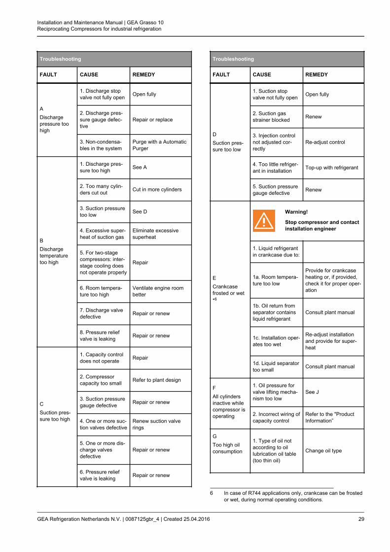
Troubleshooting
FAULT CAUSE REMEDY
ADischargepressure toohigh
1. Discharge stopvalve not fully open Open fully
2. Discharge pres-sure gauge defec-tive
Repair or replace
3. Non-condensa-bles in the system
Purge with a AutomaticPurger
BDischargetemperaturetoo high
1. Discharge pres-sure too high See A
2. Too many cylin-ders cut out Cut in more cylinders
3. Suction pressuretoo low See D
4. Excessive super-heat of suction gas
Eliminate excessivesuperheat
5. For two-stagecompressors: inter-stage cooling doesnot operate properly
Repair
6. Room tempera-ture too high
Ventilate engine roombetter
7. Discharge valvedefective Repair or renew
8. Pressure reliefvalve is leaking Repair or renew
CSuction pres-sure too high
1. Capacity controldoes not operate Repair
2. Compressorcapacity too small Refer to plant design
3. Suction pressuregauge defective Repair or renew
4. One or more suc-tion valves defective
Renew suction valverings
5. One or more dis-charge valvesdefective
Repair or renew
6. Pressure reliefvalve is leaking Repair or renew
Troubleshooting
FAULT CAUSE REMEDY
DSuction pres-sure too low
1. Suction stopvalve not fully open Open fully
2. Suction gasstrainer blocked Renew
3. Injection controlnot adjusted cor-rectly
Re-adjust control
4. Too little refriger-ant in installation Top-up with refrigerant
5. Suction pressuregauge defective Renew
ECrankcasefrosted or wet*6
Warning!
Stop compressor and contactinstallation engineer
1. Liquid refrigerantin crankcase due to:
1a. Room tempera-ture too low
Provide for crankcaseheating or, if provided,check it for proper oper-ation
1b. Oil return fromseparator containsliquid refrigerant
Consult plant manual
1c. Installation oper-ates too wet
Re-adjust installationand provide for super-heat
1d. Liquid separatortoo small Consult plant manual
FAll cylindersinactive whilecompressor isoperating
1. Oil pressure forvalve lifting mecha-nism too low
See J
2. Incorrect wiring ofcapacity control
Refer to the "ProductInformation”
GToo high oilconsumption
1. Type of oil notaccording to oillubrication oil table(too thin oil)
Change oil type
6 In case of R744 applications only, crankcase can be frostedor wet, during normal operating conditions.
Installation and Maintenance Manual | GEA Grasso 10Reciprocating Compressors for industrial refrigeration
GEA Refrigeration Netherlands N.V. | 0087125gbr_4 | Created 25.04.2016 29
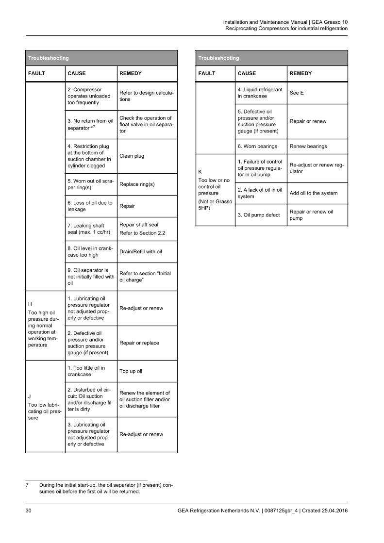
Troubleshooting
FAULT CAUSE REMEDY
2. Compressoroperates unloadedtoo frequently
Refer to design calcula-tions
3. No return from oilseparator *7
Check the operation offloat valve in oil separa-tor
4. Restriction plugat the bottom ofsuction chamber incylinder clogged
Clean plug
5. Worn out oil scra-per ring(s) Replace ring(s)
6. Loss of oil due toleakage Repair
7. Leaking shaftseal (max. 1 cc/hr)
Repair shaft sealRefer to Section 2.2
8. Oil level in crank-case too high Drain/Refill with oil
9. Oil separator isnot initially filled withoil
Refer to section “Initialoil charge”
HToo high oilpressure dur-ing normaloperation atworking tem-perature
1. Lubricating oilpressure regulatornot adjusted prop-erly or defective
Re-adjust or renew
2. Defective oilpressure and/orsuction pressuregauge (if present)
Repair or replace
JToo low lubri-cating oil pres-sure
1. Too little oil incrankcase Top up oil
2. Disturbed oil cir-cuit: Oil suctionand/or discharge fil-ter is dirty
Renew the element ofoil suction filter and/oroil discharge filter
3. Lubricating oilpressure regulatornot adjusted prop-erly or defective
Re-adjust or renew
7 During the initial start-up, the oil separator (if present) con-sumes oil before the first oil will be returned.
Troubleshooting
FAULT CAUSE REMEDY
4. Liquid refrigerantin crankcase See E
5. Defective oilpressure and/orsuction pressuregauge (if present)
Repair or renew
6. Worn bearings Renew bearings
KToo low or nocontrol oilpressure(Not or Grasso5HP)
1. Failure of controloil pressure regula-tor in oil pump
Re-adjust or renew reg-ulator
2. A lack of oil in oilsystem Add oil to the system
3. Oil pump defect Repair or renew oilpump
Installation and Maintenance Manual | GEA Grasso 10Reciprocating Compressors for industrial refrigeration
30 GEA Refrigeration Netherlands N.V. | 0087125gbr_4 | Created 25.04.2016

3 MAINTENANCE
3.1 Post start-up maintenance
After the compressor has run for the initial 100 oper-ating hours:
i. Drain the oil and refill the compressor with thecorrect amount of fresh oil.
ii. Replace the running oil discharge filter elementwith the “permanent“ filter element in accord-ance with the filter replacement instructions.
iii. Inspect suction gas filter (refer to the Compres-sor Service Instruction Manual).
iv. Exchange or clean oil suction filter element.
v. Check the compressor shaft seal for leakage. Ifexcessive (more than 1 cc/hr) replace the seal.
vi. 1) Retighten the coupling mounting bolts withthe torque settings as given by the couplingmanufacturer.2) Verify and if necessary, correct the tensionof the V-belts as given in the Grasso instruction0087516.
vii. Verify and if necessary, correct the torque set-tings of all foundation bolts as given in Com-pressor Service Instruction Manual.
3.2 First maintenance
Hint!
For complete service schedules andrequired service sets refer to Grasso"sService and Maintenance Schedules(SMS).After the refrigerating system hasbeen modified, the suction gas fil-ter(s). the oil filters and the oil shouldbe changed.
8 Time dependent on pollution.
Maintenance Number of operating hours
1008 > 100
Inspect/clean suction gas filter X
refer to Service andMaintenance
Schedules (SMS)
Renewal oil discharge filter X
Inspect/clean oil suction filter(strainer) X
Oil analysis 9 10 X
3.3 SMS FACTOR
General
The following maintenance has to be distinguished:
1. Grasso Maintenance Monitor (GMM) is appliedMaintenance A, B and C, service intervals aredetermined on measured values of GMM
2. GMM is not applied:Service intervals according to Service and Main-tenance Schedules (SMS) tables in combinationwith operating conditions
9 Take an oil sample every 3,000 running hours or once ayear and renew if any sign of discoloration and if the systemis contaminated.
10 Consult your oil supplier.
Installation and Maintenance Manual | GEA Grasso 10Reciprocating Compressors for industrial refrigeration
GEA Refrigeration Netherlands N.V. | 0087125gbr_4 | Created 25.04.2016 31

Warning!
GMM is not used: The running hoursmentioned in the SMS tables shouldonly be used as a reference for mainte-nance intervals.The number of running hours men-tioned in the SMS tables have to beadjusted accordingly depending onthe operating conditions of the com-pressor (speed, evaporating tempera-ture, condensing temperature, refriger-ant, start frequency, capacity controlsteps, etc.. This means that the serviceintervals could be significantly differ-ent.The running hours mentioned in thetables are based on a single stagecompressor running at -10oC/+35oC,NH3 at nominal speed. In this case theSMS factor = 1, in all other cases themaintenance intervals have to beadjusted accordingly.
3.4 Legend
Warning!
These operations cover routine main-tenance and are meant as a guideonly. Lack of maintenance, frequencyof stop/starting, extreme operatingconditions etc could lead to acceler-ated wear.
General;
The service and maintenance schedules use thecodes as explained in the table below;
Actions
Legend for service and maintenance schedules (SMS)
Item Code/Actions Description
1 IC Inspection / Alternatively renewal - cor-recting / Testing
2 IV Inspection Visual / Alternatively electri-cal testing
Actions
Legend for service and maintenance schedules (SMS)
Item Code/Actions Description
3 RE Renewal
4 ME Measure
5 CL Clean
Installation and Maintenance Manual | GEA Grasso 10Reciprocating Compressors for industrial refrigeration
32 GEA Refrigeration Netherlands N.V. | 0087125gbr_4 | Created 25.04.2016
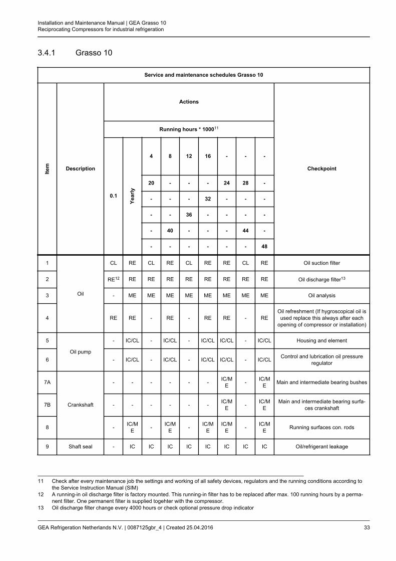
3.4.1 Grasso 10
Service and maintenance schedules Grasso 10
Item Description
Actions
Checkpoint
Running hours * 100011
0.1
Year
ly
4 8 12 16 - - -
20 - - - 24 28 -
- - - 32 - - -
- - 36 - - - -
- 40 - - - 44 -
- - - - - - 48
1
Oil
CL RE CL RE CL RE RE CL RE Oil suction filter
2 RE12 RE RE RE RE RE RE RE RE Oil discharge filter13
3 - ME ME ME ME ME ME ME ME Oil analysis
4 RE RE - RE - RE RE - REOil refreshment (If hygroscopical oil isused replace this always after each
opening of compressor or installation)
5
Oil pump
- IC/CL - IC/CL - IC/CL IC/CL - IC/CL Housing and element
6 - IC/CL - IC/CL - IC/CL IC/CL - IC/CL Control and lubrication oil pressureregulator
7A
Crankshaft
- - - - - - IC/ME - IC/M
E Main and intermediate bearing bushes
7B - - - - - - IC/ME - IC/M
EMain and intermediate bearing surfa-
ces crankshaft
8 - IC/ME - IC/M
E - IC/ME
IC/ME - IC/M
E Running surfaces con. rods
9 Shaft seal - IC IC IC IC IC IC IC IC Oil/refrigerant leakage
11 Check after every maintenance job the settings and working of all safety devices, regulators and the running conditions according tothe Service Instruction Manual (SIM)
12 A running-in oil discharge filter is factory mounted. This running-in filter has to be replaced after max. 100 running hours by a perma-nent filter. One permanent filter is supplied togehter with the compressor.
13 Oil discharge filter change every 4000 hours or check optional pressure drop indicator
Installation and Maintenance Manual | GEA Grasso 10Reciprocating Compressors for industrial refrigeration
GEA Refrigeration Netherlands N.V. | 0087125gbr_4 | Created 25.04.2016 33
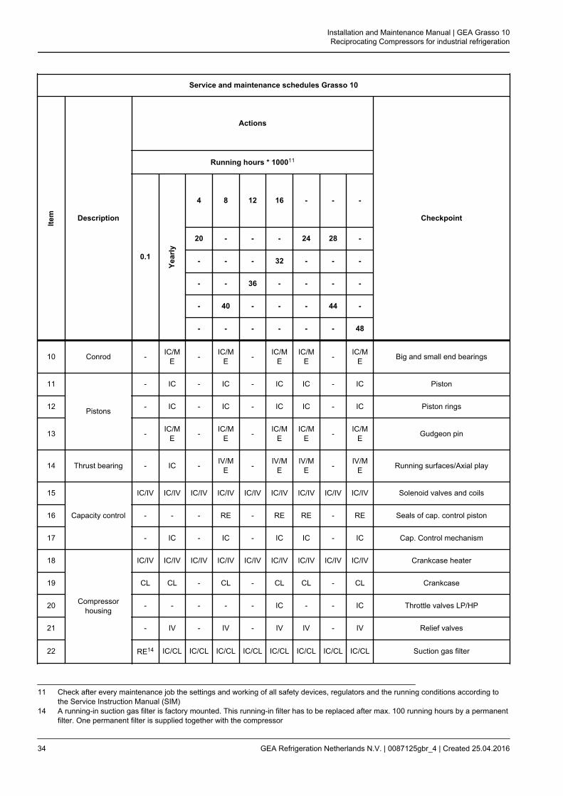
Service and maintenance schedules Grasso 10
Item Description
Actions
Checkpoint
Running hours * 100011
0.1
Year
ly
4 8 12 16 - - -
20 - - - 24 28 -
- - - 32 - - -
- - 36 - - - -
- 40 - - - 44 -
- - - - - - 48
10 Conrod - IC/ME - IC/M
E - IC/ME
IC/ME - IC/M
E Big and small end bearings
11
Pistons
- IC - IC - IC IC - IC Piston
12 - IC - IC - IC IC - IC Piston rings
13 - IC/ME - IC/M
E - IC/ME
IC/ME - IC/M
E Gudgeon pin
14 Thrust bearing - IC - IV/ME - IV/M
EIV/M
E - IV/ME Running surfaces/Axial play
15
Capacity control
IC/IV IC/IV IC/IV IC/IV IC/IV IC/IV IC/IV IC/IV IC/IV Solenoid valves and coils
16 - - - RE - RE RE - RE Seals of cap. control piston
17 - IC - IC - IC IC - IC Cap. Control mechanism
18
Compressorhousing
IC/IV IC/IV IC/IV IC/IV IC/IV IC/IV IC/IV IC/IV IC/IV Crankcase heater
19 CL CL - CL - CL CL - CL Crankcase
20 - - - - - IC - - IC Throttle valves LP/HP
21 - IV - IV - IV IV - IV Relief valves
22 RE14 IC/CL IC/CL IC/CL IC/CL IC/CL IC/CL IC/CL IC/CL Suction gas filter
11 Check after every maintenance job the settings and working of all safety devices, regulators and the running conditions according tothe Service Instruction Manual (SIM)
14 A running-in suction gas filter is factory mounted. This running-in filter has to be replaced after max. 100 running hours by a permanentfilter. One permanent filter is supplied together with the compressor
Installation and Maintenance Manual | GEA Grasso 10Reciprocating Compressors for industrial refrigeration
34 GEA Refrigeration Netherlands N.V. | 0087125gbr_4 | Created 25.04.2016

Service and maintenance schedules Grasso 10
Item Description
Actions
Checkpoint
Running hours * 100011
0.1
Year
ly
4 8 12 16 - - -
20 - - - 24 28 -
- - - 32 - - -
- - 36 - - - -
- 40 - - - 44 -
- - - - - - 48
23Discharge valves
- IC IC IC RE IC RE IC RE Valves, springs and damper rings
24 - IC IC IC IC IC IC IC IC Stroke limitor/Discharge valve seat
25 Suction valves - IC IC IC RE IC RE IC RE Valves, springs and damper rings
26
Cylinder liners
- IV - IV - IV IV - IV Cap. Control lifting mechanism
27 - IV/ME - IV/M
E - IV/ME
IV/ME - IV/M
E Dimension and running profile
28Drive
IC IC IC IC IC IC IC IC IC Alignment
29 IC IC IC IC IC IC IC IC IC V-belts
30 Electric motor Refer to specification of motor manufacturer
31
Optionals
IC IC IC IC IC IC CL/IC IC CL/IC Oil level switch
32 IC IC IC IC IC IC IC IC IC Safety switches
33 IC IC IC IC IC IC IC IC IC Gauges
34 IC IC IC IC IC IC IC IC IC Thermostats
35 IC IC IC IC IC IC IC IC IC Thermometers
36 IC IC IC IC IC IC IC IC IC Electrical control system
11 Check after every maintenance job the settings and working of all safety devices, regulators and the running conditions according tothe Service Instruction Manual (SIM)
Installation and Maintenance Manual | GEA Grasso 10Reciprocating Compressors for industrial refrigeration
GEA Refrigeration Netherlands N.V. | 0087125gbr_4 | Created 25.04.2016 35

Service and maintenance schedules Grasso 10
Item Description
Actions
Checkpoint
Running hours * 100011
0.1
Year
ly
4 8 12 16 - - -
20 - - - 24 28 -
- - - 32 - - -
- - 36 - - - -
- 40 - - - 44 -
- - - - - - 48
37 IC IC IC IC IC IC CL/IC IC CL/IC Valve oil return protection
38 IV IV IV IV IV IV IV IV IV Thermistors
39 IC IC IC IC IC IC IC IC IC Vibration dampers and bolts
40 IC/ME
IC/ME
IC/ME
IC/ME
IC/ME
IC/ME
IC/ME
IC/ME
IC/ME
Intermediate cooler and injectionvalve
41 CL CL - CL - CL CL - CL Oil separator refreshing oil and clean-ing/testing of float valve
42 - IC IC IC IC IC RE IC IC Heavy duty thrust bearing
43 CL CL CL CL CL CL CL CL CL Oil cooler, air side
44 RE RE - RE - RE RE - RE Oil cooler, oil side, refrigeration oil
45 Refer to specification of motor manufacturer Oil cooler, electric motor (fan)
11 Check after every maintenance job the settings and working of all safety devices, regulators and the running conditions according tothe Service Instruction Manual (SIM)
3.4.2 Checklist
Installation and Maintenance Manual | GEA Grasso 10Reciprocating Compressors for industrial refrigeration
36 GEA Refrigeration Netherlands N.V. | 0087125gbr_4 | Created 25.04.2016

Service and maintenance schedules Grasso RECIPROCATING COMPRESSORS
Item Description Checked/Remarks/Notes Checkpoint/Setting/Value
A Compressor type
B Machine number
C Date
D Running hours
E Refrigerant
E Evaporating temperature/pressure To/Po
F Intermediate temperature/pressure Tm/Pm
G Discharge temperature/pressure Tc/Pc
H Oil lubricating pressure
I Oil control pressure
J GeneralNotes
1
Oil
Oil suction filter
2 Oil discharge filter
3 Oil analysis
4 Oil refreshment (If hygroscopic oil is used replace this always after eachopening of compressor or installation)
5Oil pump
Housing and element
6 Control and lubrication oil pressure regulator
7 Crankshaft Main and intermediate bearing bushes and running surfaces
Installation and Maintenance Manual | GEA Grasso 10Reciprocating Compressors for industrial refrigeration
GEA Refrigeration Netherlands N.V. | 0087125gbr_4 | Created 25.04.2016 37
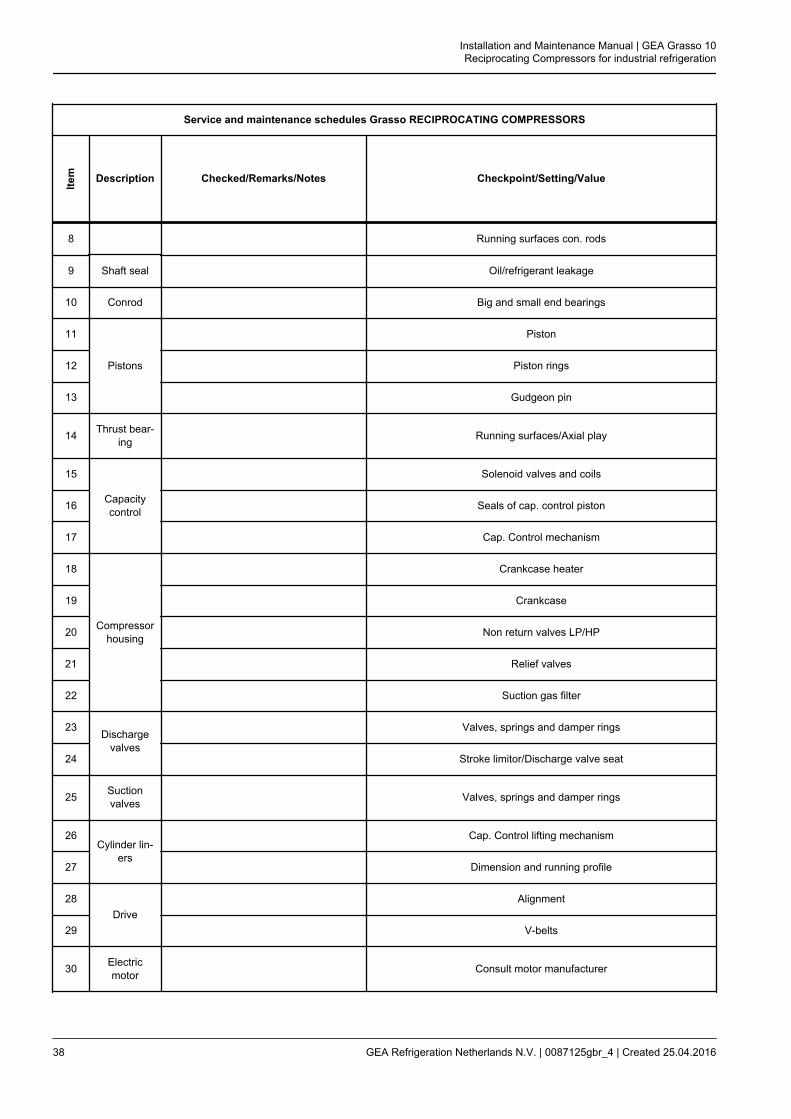
Service and maintenance schedules Grasso RECIPROCATING COMPRESSORS
Item Description Checked/Remarks/Notes Checkpoint/Setting/Value
8 Running surfaces con. rods
9 Shaft seal Oil/refrigerant leakage
10 Conrod Big and small end bearings
11
Pistons
Piston
12 Piston rings
13 Gudgeon pin
14 Thrust bear-ing Running surfaces/Axial play
15
Capacitycontrol
Solenoid valves and coils
16 Seals of cap. control piston
17 Cap. Control mechanism
18
Compressorhousing
Crankcase heater
19 Crankcase
20 Non return valves LP/HP
21 Relief valves
22 Suction gas filter
23Discharge
valves
Valves, springs and damper rings
24 Stroke limitor/Discharge valve seat
25 Suctionvalves Valves, springs and damper rings
26Cylinder lin-
ers
Cap. Control lifting mechanism
27 Dimension and running profile
28Drive
Alignment
29 V-belts
30 Electricmotor Consult motor manufacturer
Installation and Maintenance Manual | GEA Grasso 10Reciprocating Compressors for industrial refrigeration
38 GEA Refrigeration Netherlands N.V. | 0087125gbr_4 | Created 25.04.2016

Service and maintenance schedules Grasso RECIPROCATING COMPRESSORS
Item Description Checked/Remarks/Notes Checkpoint/Setting/Value
31
Optionals
Oil level switch
32 Safety switches
33 Gauges
34 Thermostats
35 Thermometers
36 Electrical control system
37 Valve oil return protection
38 Thermistors
39 Vibration dampers and bolts
40 Intermediate cooler and injection valve
41 Oil separator refreshing oil and cleaning/testing of float valve
42 Heavy duty thrust bearing
43 Oil cooler, air side
44 Oil cooler, oil side, refrigeration oil
45 Consult motor manufacturer Oil cooler, electric motor (fan)
46 Cylinder head water cooling system
Settings pressure safeties
Safety Remark Value
1 Suction pressure
2 LP discharge pressure (safety) two stage only
3 LP discharge pressure (limitor) two stage only,TUV
4 High pressure suction (safety) two stage only
5 High pressure (safety)
Installation and Maintenance Manual | GEA Grasso 10Reciprocating Compressors for industrial refrigeration
GEA Refrigeration Netherlands N.V. | 0087125gbr_4 | Created 25.04.2016 39

Settings pressure safeties
Safety Remark Value
6 High pressure (limitor) TUV only
7 OIl differential pressure
Installation and Maintenance Manual | GEA Grasso 10Reciprocating Compressors for industrial refrigeration
40 GEA Refrigeration Netherlands N.V. | 0087125gbr_4 | Created 25.04.2016
Installation and Maintenance Manual | GEA Grasso 10Reciprocating Compressors for industrial refrigeration
GEA Refrigeration Netherlands N.V. | 0087125gbr_4 | Created 25.04.2016 41

© G
EA G
roup
AG
. All
right
s re
serv
ed. S
ubje
ct to
mod
ifica
tion
GEA Refrigeration Technologies
GEA Refrigeration Netherlands N.V.
Parallelweg 27, 5223 AL ‘s-Hertogenbosch, The NetherlandsPhone: +31 73 [email protected], www.gea.com
GEA Group is a global engineering company with multi-billion euro sales and operations in more than 50 countries. Founded in 1881, the company is one of the largest providers of innovative equipment and process technology. GEA Group is listed in the STOXX® Europe 600 Index.
We live our values.Excellence • Passion • Integrity • Responsibility • GEA-versity