G GE Power Management 369 Motor Management Relay.
31
g GE Power Management 369 Motor Management Relay 369 Motor Management Relay
Transcript of G GE Power Management 369 Motor Management Relay.

gGE Power Management
369 Motor Management Relay369 Motor Management Relay
g GE Power Management 369 Motor Management Relay
Offering optimum motor protection in situations where other relays cannot, the 369 Motor Management Relaypossess the unique feature of its ability to “learn” individual motor parameters, giving it the flexibility to adapt to each application by “learning” values of motor inrush current, negative sequence current K factor, cool down rates, start thermal capacity and acceleration time.
g GE Power Management 369 Motor Management Relay
Presentation Presentation OverviewOverview
ApplicationsApplications
Protection and Protection and ControlControl
Metering andMetering and MonitoringMonitoring
Inputs and Inputs and OutputsOutputs
User InterfaceUser Interface
OrderingOrdering CommunicationsCommunications
Typical WiringTypical Wiring

ApplicationsApplications
g GE Power Management 369 Motor Management Relay
MAINMAIN
Fans
Pumps
Compressors
Milling
Crushers
Grinders
Conveyers
Shredders
Extruders
Chippers
Debarkers
Refiners
Blowers
Cranes
Chillers

g GE Power Management 369 Motor Management Relay
369FUNCTIONAL
BLOCKDIAGRAM
MAINMAIN
5 0 G5 2
4 I S O L A T E DA N A L O GO U T P U T S
M E T E R I N GV , W , V a r , V A , P F , H z
M E T E R I N GA , C e l s i u s5 1 3 7
5 0
B A C K U P
O P T IO N A L M E T E R IN G (M )
B U SVV
5 5
5 0
2 7 4 7 5 9
1 4
8 7
4 9 3 8
8 6
7 4
1 4
8 7
S P E E D D E V I C E
3
D I F F E R E N T I A L
I N P U T S
R T D s
A M B I E N T A I R
B R E A K E RO R F U S E D
C O N T A C T O R
R S 2 3 2
S T A R T
R S 4 8 5
R S 4 8 5
R S 4 8 5
S T A T O RB E A R I N GA M B I E N T
8 4 0 7 0 1 A 9 .C D R
R E L A Y C O N T A C T S
A M B I E N T
S T A T O R
B E A R I N G
5 0 G5 1 G
4 66 6

g GE Power Management 369 Motor Management Relay
DEVICE PROTECTION
Induction & Synchronous Induction & Synchronous MotorsMotors
Large Induction Motors Synchronous Motors
MAINMAIN

g GE Power Management 369 Motor Management Relay
ProtectionProtection
Stator winding overtemperature (R option)
Bearing over-temperature (R option)
Multiple starts
Overloads
15 standard overload curves
Ground fault
Undercurrent
Phase reversal (M option)
Variable lock out time
“Learns” individual motor parameters
Short circuit
User defined overload FlexCurveTM
Locked rotor
Rapid trip/mechanical jam
Unbalance/single phasing
Backspin Detection (B option)
MAINMAIN

g GE Power Management
Thermal modeling of stator and rotor
RTD (resistance temperature unit) and negative sequence feedback (R option)
Overload protection (15 standard curves plus custom FlexCurve™”)
Adapts for hot or cold starts
Power factor with time delays (M option)
Backspin detection for protection of downhole pumps
369 Motor Management Relay
Motor Motor ProtectionProtection
MAINMAIN
g GE Power Management
Start and RunningStart and Running
369 Motor Management Relay
Motor is protected under both Acceleration and Running conditions
The 369 can trigger an alarm or trip the motor based on:
normal acceleration time number of starts per hour multiple starts time between starts motor overload conditions
MAINMAIN
g GE Power Management
One of 15 standard overload curves may be programmed based on motor manufacturer’s locked rotor time capability.
Alternately the user may program in a custom curve using the built-in FlexCurve™ function.
369 Motor Management Relay
OverloadOverload
MAINMAIN
View 15 Standard Overload Curves
g GE Power Management 369 Motor Management Relay
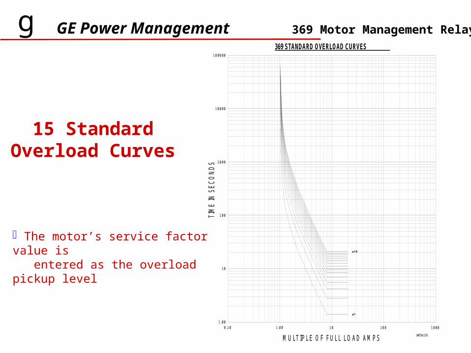
15 Standard Overload Curves
The motor’s service factor value is entered as the overload pickup level
369 STANDARD OVERLOAD CURVES100000
10000
1000
100
10
1.000.10 1.00
M U LTIPLE O F FU LL LO AD AM PS
TIM
E IN
SEC
OND
S
10 100 1000
840719A1.CDR

1) Programmed 369 Custom Curve
2) Running Safetime (Stator Limit)
3) Acceleration Safetime(Rotor Limit)4) Motor Current @ 100% Voltage
5) Motor Current @ 80% Voltage
g GE Power Management
FlexCurve can be used to protectmotors which have different rotorand stator damage, allowing totalmotor design capacity with complete protection.
When a FlexCurve is programmed,the 369 develops a smoothcustom overload curve within a selected range.
369 Motor Management Relay
FlexCurve™FlexCurve™
g GE Power Management 369 Motor Management Relay
Thermal ModelingThermal Modeling
The Thermal Model within the 369 has the ability to computethe motor I2t value based on actual motor load current.
thermal model calculates value in terms of thermal capacity used
RTDs (resistance temperature units) measuring stator temperature act as a thermal capacity check to confirm value calculated by thermal model. RTDs may be used for monitoring stator, bearing, ambient, or other temperature monitoring.
thermal capacity used is then updated to reflect the higher of the two values
MAINMAIN

g GE Power Management 369 Motor Management Relay
MotorMatch modifies the initially entered relay parameters to match actual measured motor characteristics. The key elements include:
accumulated I2t in the memory RTD input to the memory learned cooldown time from run to stop learned cooldown time from run- overload to run-normal learned acceleration time learned negative sequence contribution (K-factor)
Motor MatchMotor Match
MAINMAIN
g GE Power Management 369 Motor Management Relay
RTD Hot Motor RTD Hot Motor CompensationCompensation
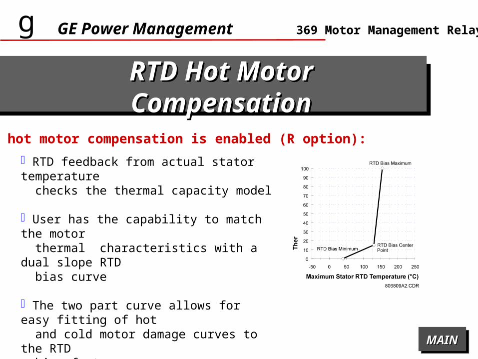
When hot motor compensation is enabled (R option):
RTD feedback from actual stator temperature checks the thermal capacity model
User has the capability to match the motor thermal characteristics with a dual slope RTD bias curve
The two part curve allows for easy fitting of hot and cold motor damage curves to the RTD bias feature
MAINMAIN

g GE Power Management 369 Motor Management Relay
User InterfacesUser Interfaces
PC Software for setting, monitoring Flash Memory for Future Upgrades or industry modifications 40 character alpha-numeric backlit LCD display Five Target LED indicators 3 RS485 com port (ModBus® RTU) Front Panel RS232 port Optional Fiber Optic Port Optional Profibus Port
MAINMAIN

g GE Power Management
Full remote local control Power factor control Current and Voltage
Sensing Two speed motor Testing Switch Emergency Restart
369 Motor Management Relay
ControlControl
MAINMAIN

g GE Power Management
Event Recorder (Last 40 Events)
Trace Memory (16 Cycle Waveform Capture)
Complete Self Checking
369 Motor Management Relay
MonitoriMonitoringng
MAINMAIN

g GE Power Management 369 Motor Management Relay
Individual Voltages & Currents Real, Reactive & Apparent Power Demand Real & Reactive Power Costs & Usage Running & Maximum Demand Levels Power Factor Temperatures Backspin Frequency and Predication Time
MeteriMeteringng
MAINMAIN

g GE Power Management 369 Motor Management Relay
MAINMAIN
M O T O R M A N A G E M E N T R E L A Y ®
A C T U A LV A L U E S
R E S E TC L E A RE N T E R
S E TP O I N T S
H E L P
P A G E
P A G E
L I N E
L I N E
V A L U E
V A L U E
DIS PLAY40 Character alpha-num ericLC D display for view ing actual values, causesof alarm s and trips, and program m ing setpoints
S TATU S IN D IC ATO RSLE Ds indicate if m otor isbacksp inn ing, RRTD isconnected, m etering isenabled and com . status
HELP KEYHelp key can be pressed atany tim e to provide additio nalinform ation
C O M PU T ER IN T ERFA C ERS 232 co m m port for con-necting to a PC . U se fordow nloading setpoints,m onitoring , data collectio n &printing reports.
KEY PA DU sed to select the displayof actual values, causes of alarm s, causes of trips, faultdiagnosis, and to programsetpo ints
Rugged, co rrosion andflam e retardent case.

g GE Power Management 369 Motor Management Relay
MAINMAIN
840702BB.CDR
FIBER O PTIC DAT A LIN K ( F )Fo r harsh enviro m ents and orhook up to RRTD
PRO FIBU S PO RT ( P )
BA CKS PIN DETEC TIO N ( B )0-575V RM S
3 x RS 485 Ports3 Independent m o dbuschannels
A N A LO G O U TPU T ( M )
V O LTA G E IN PU T S ( M )0-240V w ye or delta V Tconnections.
G RO U N D C T IN PU TS5A , 1A and 50:0.25 taps
12 RTD IN PU TS ( R )Field selectable type
C O N TRO L PO W ERHI: 50-300 V DC / 40-265 VA CLO : 20-60 V DC / 20-48 VA C
C ustom er A ccessib leFuse
D IG ITA L IN PU TSG E P o w e r M a n a g e m e n t
T e l : ( 9 0 5 ) 2 9 4 - 6 2 2 2( N o r t h A m e r i c a ) 1 8 0 0 5 4 7 - 8 6 2 9
T E C H N I C A L S U P P O R T
F a x : ( 9 0 5 ) 2 0 1 - 2 0 9 8w w w . g e . c o m / i n d s y s / p m
13
03
-0
06
6-
AA
g M U LT I L I N
g M U LT I L I N
I N P U T P O W E R :
M O D E L : 3 6 9 - H I - R - B - F - P
M A X I M U M C O N T A C T R A T I N G2 5 0 V A C 1 0 A R E S I S T I V E1 / 4 H P 1 2 5 V A C 1 / 2 H P 2 5 0 V A C
S E R I A L N o : M 5 3 B 9 9 0 0 0 0 2 6
F I R M W A R E : 5 3 A 7 0 0 C 0 . 0 0 0
P O L L U T I O N D E G R E E : 2I P C O D E : X O
5 0 - 3 0 0 V D C4 0 - 2 6 5 V A C5 7 8 m A M A X .5 0 / 6 0 H z o r D C
M O D :
1 2 R T D s :
B A C K S P I N
F I B E R O P T I C P O R T
P R O F I B U S
O P T I O N S
I N S U L A T I V E V O L T A G E : 2
N O N EO V E R V O L T A G E C A T A G O R Y : 1

g GE Power Management 369 Motor Management Relay
“Modbus® protocol“ (Modicon, Bailey, Siemens, Allen Bradley, GE Fanuc, Square D, Honeywell, Foxboro, Intellution FIX/DMACS, Wonderware In Touch, etc. )
CommunicatiCommunicationsons
Windows basedAccess all:
Actual ValuesSetpointsStatusEvent records
Oscillography
Graphical trending Setpoint programming Setpoint files Download update firmware to Flash memory
MAINMAIN
g GE Power Management 369 Motor Management Relay
MeteringMetering
average and individual phase currents RTD temperatures (hottest, individual, maximum) (R option) unbalance ratio ground leakage current thermal capacity remaining / estimated time to trip at present overload level motor load as a percent of full load phase to phase or phase to neutral voltage voltage (meter option) W, var, Mwhr, PF, Hz (M option)
Actual ValuesActual Values
MAINMAIN

g GE Power Management 369 Motor Management Relay
MonitoringMonitoring
immediate overload/stall warning ground fault mechanical jam unbalance undercurrent RTD overtemperature, broken RTD sensor, low temperature RTD (R option) self-test-service under/overvoltage (M option) low power factor (M option)
Prior AlarmsPrior Alarms
MAINMAIN

g GE Power Management 369 Motor Management Relay
MonitoringMonitoring
Fault DiagnosisFault Diagnosis
369 displays the cause of the trip and will show the remaining lock-out time if applicable cause of the last trip and pre-trip values can be recalled for rapid fault diagnosis.
MAINMAIN
g GE Power Management 369 Motor Management Relay
Statistical Data (StatTracStatistical Data (StatTracTMTM))
StatTracTM provides statistical data of motor use for operations monitoring, maintenance, and fault diagnosis.
Using the Keypad, the user can display:
MonitoringMonitoring
running hours and number of starts since last commissioning number of all trips number of specific types of trips total Watt-hours (M option)
MAINMAIN

g GE Power Management 369 Motor Management Relay
InputsInputs
Speed Switch Speed Switch InputInput Differential Relay Differential Relay InputInput
Spare InputSpare Input
enables the user to use an external speed device
provided terminals to accept contact closure from an external differential relay all protective functions grouped through one main relay
spare input terminals configurable to represent either a standard contact input (ie-pressure switch), or a specific contact input (circuit breaker/contactor status) 52a or 52b contact from a circuit breaker = positive identification of the position of the breaker(open or closed)
MAINMAIN
General Switch and Digital CountersGeneral Switch and Digital Counters Any of the Switch inputs can be configured as a General or Digital Counter

g GE Power Management 369 Motor Management Relay
OutputsOutputs
4 Output Relay Contacts4 Output Relay Contacts Trip Relay as main latched output relay Alarm output relay (latched or unlatched) Auxiliary 1 output relay (latched or unlatched) Auxiliary 2 output relay
4 Fully Programmable Analog Outputs (M option)4 Fully Programmable Analog Outputs (M option) Used to indicate one of motor thermal capacity used, motor current, hottest stator RTD, bearing RTD, CT secondary current, or other various parameters
MAINMAIN
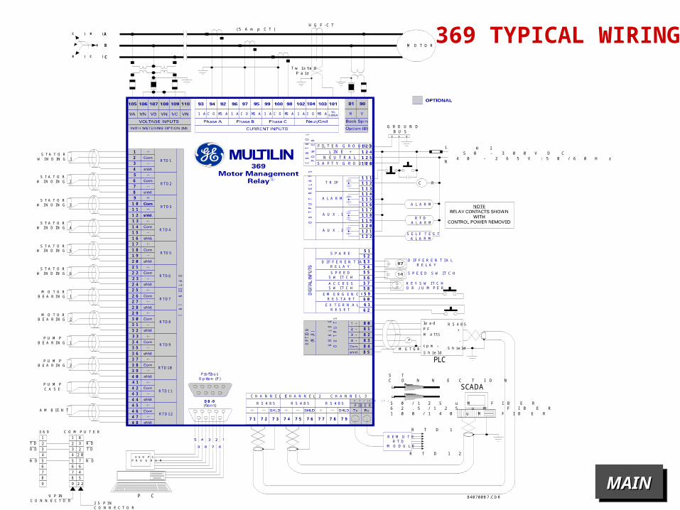
369 TYPICAL WIRING
MAINMAIN
G R O U N D B U S
840700B7.CDR
DB -9(front)
S T A T O RW I N D I N G 1
M E T E R
l o a d
PLC
SCADA
R S 4 8 5P F +W a t ts
c p m -
S h i e l dS h i e l d
-
S T A T O RW I N D I N G 2
S T A T O RW I N D I N G 3
S T A T O RW I N D I N G 4
S T A T O RW I N D I N G 5
S T A T O RW I N D I N G 6
M O T O RB E A R I N G 1
M O T O RB E A R I N G 2
P U M PB E A R I N G 1
P U M PB E A R I N G 2
P U M PC A S E
A M B I E N T
3 6 9
T D
T DR D
R D
N D N D
C O M P U T E R
2 5 P I NC O N N E C T O R
9 P I NC O N N E C T O R
( 5 A m p C T )
T w i s t e dP a i r
H I5 0 - 3 0 0 V D C
4 0 - 2 6 5 V : 5 0 / 6 0 H z
R T D 1
S TC O N N E C T I O N
5 0 / 1 2 5 u M F I B E R6 2 . 5 / 1 2 5 u M F I B E R1 0 0 / 1 4 0 u M F I B E R
P C
R T D 1 2
C R
A
B
C
L
N
C ( B )
A
B ( C )
H G F - C T
M O T O R
1 A 1 AC O M5 A C O MC O M5 A 1 A 5 A 5 A VNC O M 1 A
C H A N N E L 1
OP
TIO
N ( R
)
C H A N N E L 2 C H A N N E L 3
R E M O T ER T D
M O D U L E
R S 4 8 5 R S 4 8 5 R S 4 8 5 F I B E R
7 1 7 4 7 77 3 7 6 7 97 2 7 5 7 8
8 0
8 2
8 48 5
8 1
8 3
4
1 2
1 6
2 0
2 4
2 8
3 2
3 6
4 0
4 4
4 8
8
3
1 1
1 5
1 9
2 3
2 7
3 1
3 5
3 9
4 3
4 7
7
2
1 0
1 4
1 8
2 2
2 6
3 0
3 4
3 8
4 2
4 6
6
1
9
1 3
1 7
2 1
2 5
2 9
3 3
3 7
4 1
4 5
5
AN
AL
OG
OU
TP
UT
S
OP
TIO
N
(M,B
)
RTD1
RTD3
RTD4
RTD5
RTD6
RTD7
RTD8
RTD9
RTD10
RTD11
RTD12
RTD2
S P A R E
D I F F E R E N T I A LR E L A Y
R T DA L A R M
S E L F T E S TA L A R M
A L A R M
K E Y S W I T C HO R J U M P E R
S P E E D S W I T C H
D I F F E R E N T I A LR E L A Y
S P E E DS W I T C H
A C C E S SS W I T C H
E M E R G E N C YR E S T A R T
E X T E R N A LR E S E T
5 1
5 9
6 1
5 2
6 0
6 2
5 35 45 55 65 75 8
1 1 1
1 2 61 2 51 2 41 2 3
1 1 21 1 31 1 41 1 51 1 61 1 71 1 81 1 91 2 01 2 11 2 2
OU
TP
UT
RE
LA
YS
T R I P
A L A R M
A U X . 1
A U X . 2
F I L T E R G R O U N DL I N E +
N E U T R A L -S A F T Y G R O U N DC
ON
TR
OL
PO
WE
R
3 6 9 P CP R O G R A M
O P T I O N ( F )
11 8
22 3
66 6
44 2 0
88 5
33 2
77 4
55 7
99 2 2
R
Profi busOp tion (P)
GE Power Managementg
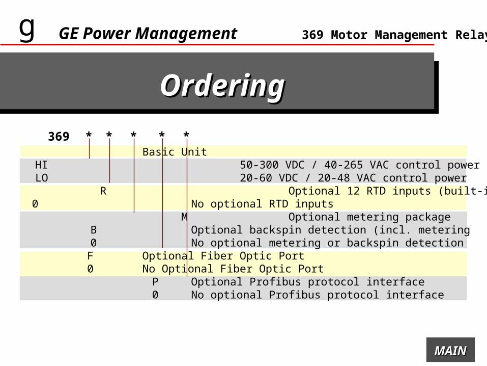
OrderinOrderingg
369 Motor Management Relay
369 Basic Unit HI 50-300 VDC / 40-265 VAC control power LO 20-60 VDC / 20-48 VAC control power R Optional 12 RTD inputs (built-in)
0 No optional RTD inputs M Optional metering package
B Optional backspin detection (incl. metering 0 No optional metering or backspin detection
F Optional Fiber Optic Port 0 No Optional Fiber Optic Port P Optional Profibus protocol interface 0 No optional Profibus protocol interface
369 * * * * *
MAINMAIN

gGE Power Management
369 Motor Management Relay369 Motor Management Relay
Contact Information: