369 Motor Management Relay - GE Grid Solutions · GE Multilin 369 Motor Management Relay...
294
GE Multilin 215 Anderson Avenue, Markham, Ontario, Canada L6E 1B3 Tel: (905) 294-6222, 1-800-547-8629 (North America) Fax: (905) 201-2098 Internet: http://www.GEmultilin.com 369 Motor Management Relay Instruction Manual 369 Revision: 3.4x Manual P/N: 1601-0077-BU GE Publication Number: GEK-106288R Copyright © 2010 GE Multilin Digital Energy Multilin *1601-0077-BU* GE Multilin's Quality Management System is registered to ISO9001:2000 QMI # 005094 UL # A3775
Transcript of 369 Motor Management Relay - GE Grid Solutions · GE Multilin 369 Motor Management Relay...
GE Multilin
215 Anderson Avenue, Markham, Ontario, Canada L6E 1B3
Tel: (905) 294-6222, 1-800-547-8629 (North America)Fax: (905) 201-2098
Internet: http://www.GEmultilin.com
369 Motor Management RelayInstruction Manual
369 Revision: 3.4x
Manual P/N: 1601-0077-BU
GE Publication Number: GEK-106288R
Copyright © 2010 GE Multilin
Digital EnergyMultilin
*1601-0077-BU*
GE Multilin's Quality Management System is registered to
ISO9001:2000
QMI # 005094UL # A3775

© 2010 GE Multilin Incorporated. All rights reserved.
GE Multilin 369 Motor Management Relay instruction manual for revision 3.4x.
369 Motor Management Relay, is a registered trademark of GE Multilin Inc.
The contents of this manual are the property of GE Multilin Inc. This documentation is furnished on license and may not be reproduced in whole or in part without the permission of GE Multilin. The content of this manual is for informational use only and is subject to change without notice.
Part numbers contained in this manual are subject to change without notice, and should therefore be verified by GE Multilin before ordering.
Part number: 1601-0077-BU (July 2010)
TABLE OF CONTENTS
369 MOTOR MANAGEMENT RELAY– INSTRUCTION MANUAL TOC–1
Table of Contents
1: INTRODUCTION ORDERING ........................................................................................................................................... 1-1GENERAL OVERVIEW ........................................................................................................... 1-1ORDERING ............................................................................................................................ 1-2ACCESSORIES ....................................................................................................................... 1-3FIRMWARE HISTORY ............................................................................................................ 1-3PC PROGRAM (SOFTWARE) HISTORY ............................................................................... 1-4369 RELAY FUNCTIONAL SUMMARY ................................................................................ 1-5RELAY LABEL DEFINITION ................................................................................................... 1-8
2: PRODUCT DESCRIPTION OVERVIEW ........................................................................................................................................... 2-9GUIDEFORM SPECIFICATIONS ............................................................................................ 2-9METERED QUANTITIES ........................................................................................................ 2-10PROTECTION FEATURES ...................................................................................................... 2-10ADDITIONAL FEATURES ....................................................................................................... 2-12
SPECIFICATIONS ............................................................................................................................... 2-13INPUTS .................................................................................................................................. 2-13OUTPUTS ............................................................................................................................... 2-15METERING ............................................................................................................................. 2-16COMMUNICATIONS .............................................................................................................. 2-17PROTECTION ELEMENTS ...................................................................................................... 2-18MONITORING ELEMENTS .................................................................................................... 2-21CONTROL ELEMENTS ........................................................................................................... 2-22ENVIRONMENTAL SPECIFICATIONS .................................................................................... 2-22LONG-TERM STORAGE ......................................................................................................... 2-24APPROVALS/CERTIFICATION ............................................................................................... 2-24TYPE TEST STANDARDS ...................................................................................................... 2-24PRODUCTION TESTS ............................................................................................................ 2-25
3: INSTALLATION MECHANICAL INSTALLATION ..................................................................................................... 3-27MECHANICAL INSTALLATION .............................................................................................. 3-27
TERMINAL IDENTIFICATION ......................................................................................................... 3-29369 RELAY TERMINAL LIST ................................................................................................ 3-29269 TO 369 RELAY CONVERSION TERMINAL LIST ........................................................ 3-31MTM-369 RELAY CONVERSION TERMINAL LIST ........................................................... 3-34MPM-369 RELAY CONVERSION TERMINAL LIST ........................................................... 3-35TERMINAL LAYOUT .............................................................................................................. 3-36
ELECTRICAL INSTALLATION ......................................................................................................... 3-37TYPICAL WIRING DIAGRAM ................................................................................................ 3-37TYPICAL WIRING .................................................................................................................. 3-37CONTROL POWER ................................................................................................................ 3-38PHASE CURRENT (CT) INPUTS ........................................................................................... 3-38GROUND CURRENT INPUTS ............................................................................................... 3-39ZERO SEQUENCE GROUND CT PLACEMENT .................................................................... 3-40PHASE VOLTAGE (VT/PT) INPUTS ..................................................................................... 3-40BACKSPIN VOLTAGE INPUTS .............................................................................................. 3-41RTD INPUTS ......................................................................................................................... 3-42
TOC–2 369 MOTOR MANAGEMENT RELAY– INSTRUCTION MANUAL
TABLE OF CONTENTS
DIGITAL INPUTS ................................................................................................................... 3-42ANALOG OUTPUTS .............................................................................................................. 3-43REMOTE DISPLAY ................................................................................................................. 3-43OUTPUT RELAYS .................................................................................................................. 3-44RS485 COMMUNICATIONS ................................................................................................ 3-45TYPICAL TWO-SPEED (LOW SPEED/HIGH SPEED) MOTOR WIRING ............................ 3-47TYPICAL MOTOR FORWARD/REVERSE WIRING ............................................................... 3-49
REMOTE RTD MODULE (RRTD) .................................................................................................... 3-51MECHANICAL INSTALLATION .............................................................................................. 3-51ELECTRICAL INSTALLATION ................................................................................................. 3-53
CT INSTALLATION ............................................................................................................................. 3-54PHASE CT INSTALLATION ................................................................................................... 3-545 AMP GROUND CT INSTALLATION .................................................................................. 3-55HGF (50:0.025) GROUND CT INSTALLATION ............................................................... 3-56
4: USER INTERFACES FACEPLATE INTERFACE ................................................................................................................. 4-57DISPLAY ................................................................................................................................. 4-57LED INDICATORS ................................................................................................................. 4-57RS232 PROGRAM PORT .................................................................................................... 4-58KEYPAD ................................................................................................................................. 4-58SETPOINT ENTRY .................................................................................................................. 4-59
ENERVISTA 369 SETUP INTERFACE .......................................................................................... 4-60HARDWARE AND SOFTWARE REQUIREMENTS ................................................................. 4-60INSTALLING ENERVISTA 369 SETUP ................................................................................. 4-60
CONNECTING ENERVISTA 369 SETUP TO THE RELAY ...................................................... 4-63CONFIGURING SERIAL COMMUNICATIONS ....................................................................... 4-63USING THE QUICK CONNECT FEATURE ............................................................................ 4-65CONFIGURING ETHERNET COMMUNICATIONS ................................................................. 4-65CONNECTING TO THE RELAY .............................................................................................. 4-67
WORKING WITH SETPOINTS AND SETPOINT FILES ........................................................... 4-69ENGAGING A DEVICE ........................................................................................................... 4-69ENTERING SETPOINTS ......................................................................................................... 4-69FILE SUPPORT ...................................................................................................................... 4-71USING SETPOINTS FILES ..................................................................................................... 4-71
UPGRADING RELAY FIRMWARE ................................................................................................. 4-84DESCRIPTION ........................................................................................................................ 4-84SAVING SETPOINTS TO A FILE ............................................................................................ 4-84LOADING NEW FIRMWARE ................................................................................................. 4-84
ADVANCED ENERVISTA 369 SETUP FEATURES ................................................................... 4-87TRIGGERED EVENTS ............................................................................................................. 4-87TRENDING ............................................................................................................................. 4-87WAVEFORM CAPTURE (TRACE MEMORY) ......................................................................... 4-89MOTOR START DATA LOGGER ........................................................................................... 4-91DATA LOGGER ...................................................................................................................... 4-91MOTOR HEALTH REPORT ................................................................................................... 4-97PHASORS .............................................................................................................................. 4-97EVENT RECORDER ................................................................................................................ 4-99MODBUS USER MAP ........................................................................................................... 4-100VIEWING ACTUAL VALUES .................................................................................................. 4-100
USING ENERVISTA VIEWPOINT WITH THE 369 RELAY ..................................................... 4-102PLUG AND PLAY EXAMPLE ................................................................................................. 4-102

TABLE OF CONTENTS
369 MOTOR MANAGEMENT RELAY– INSTRUCTION MANUAL TOC–3
5: SETPOINTS OVERVIEW ........................................................................................................................................... 5-107SETPOINTS MAIN MENU ..................................................................................................... 5-107
S1 369 SETUP .................................................................................................................................... 5-111SETPOINT ACCESS ............................................................................................................... 5-111DISPLAY PREFERENCES ....................................................................................................... 5-111369 COMMUNICATIONS ..................................................................................................... 5-112REAL TIME CLOCK ............................................................................................................... 5-115WAVEFORM CAPTURE ......................................................................................................... 5-116DATA LOGGER ...................................................................................................................... 5-117EVENT RECORDS .................................................................................................................. 5-118MESSAGE SCRATCHPAD ...................................................................................................... 5-118DEFAULT MESSAGES ........................................................................................................... 5-119CLEAR/PRESET DATA .......................................................................................................... 5-120MODIFY OPTIONS ................................................................................................................ 5-121FACTORY SERVICE ............................................................................................................... 5-121
S2 SYSTEM SETUP ............................................................................................................................ 5-122DESCRIPTION ........................................................................................................................ 5-122CT/VT SETUP ...................................................................................................................... 5-122MONITORING SETUP ........................................................................................................... 5-125BLOCK FUNCTIONS ............................................................................................................. 5-129OUTPUT RELAY SETUP ........................................................................................................ 5-130CONTROL FUNCTIONS ........................................................................................................ 5-131
S3 OVERLOAD PROTECTION ....................................................................................................... 5-141DESCRIPTION ........................................................................................................................ 5-141THERMAL MODEL ................................................................................................................ 5-142OVERLOAD CURVES ............................................................................................................ 5-144OVERLOAD ALARM .............................................................................................................. 5-154
S4 CURRENT ELEMENTS ............................................................................................................... 5-155DESCRIPTION ........................................................................................................................ 5-155SHORT CIRCUIT .................................................................................................................... 5-155MECHANICAL JAM ............................................................................................................... 5-156UNDERCURRENT .................................................................................................................. 5-157CURRENT UNBALANCE ....................................................................................................... 5-158GROUND FAULT ................................................................................................................... 5-159
S5 MOTOR START/INHIBITS ......................................................................................................... 5-161DESCRIPTION ........................................................................................................................ 5-161ACCELERATION TRIP ............................................................................................................ 5-161START INHIBITS .................................................................................................................... 5-162BACKSPIN DETECTION ........................................................................................................ 5-163
S6 RTD TEMPERATURE ................................................................................................................... 5-165DESCRIPTION ........................................................................................................................ 5-165LOCAL RTD PROTECTION ................................................................................................... 5-165REMOTE RTD PROTECTION ................................................................................................ 5-166OPEN RTD ALARM .............................................................................................................. 5-169SHORT/LOW TEMP RTD ALARM ....................................................................................... 5-169LOSS OF RRTD COMMS ALARM ....................................................................................... 5-170
S7 VOLTAGE ELEMENTS ................................................................................................................ 5-171DESCRIPTION ........................................................................................................................ 5-171UNDERVOLTAGE ................................................................................................................... 5-171OVERVOLTAGE ...................................................................................................................... 5-172PHASE REVERSAL ................................................................................................................. 5-173UNDERFREQUENCY .............................................................................................................. 5-175OVERFREQUENCY ................................................................................................................. 5-176
TOC–4 369 MOTOR MANAGEMENT RELAY– INSTRUCTION MANUAL
TABLE OF CONTENTS
S8 POWER ELEMENTS .................................................................................................................... 5-177DESCRIPTION ........................................................................................................................ 5-177LEAD POWER FACTOR ........................................................................................................ 5-178LAG POWER FACTOR .......................................................................................................... 5-179POSITIVE REACTIVE POWER ............................................................................................... 5-179NEGATIVE REACTIVE POWER ............................................................................................. 5-180UNDERPOWER ...................................................................................................................... 5-182REVERSE POWER ................................................................................................................. 5-183
S9 DIGITAL INPUTS .......................................................................................................................... 5-184DIGITAL INPUT FUNCTIONS ................................................................................................ 5-184SPARE SWITCH ..................................................................................................................... 5-186EMERGENCY RESTART ......................................................................................................... 5-187DIFFERENTIAL SWITCH ........................................................................................................ 5-187SPEED SWITCH ..................................................................................................................... 5-188REMOTE RESET ..................................................................................................................... 5-189
S10 ANALOG OUTPUTS ................................................................................................................. 5-190ANALOG OUTPUTS .............................................................................................................. 5-190
S11 369 TESTING ............................................................................................................................. 5-192TEST OUTPUT RELAYS ......................................................................................................... 5-192TEST ANALOG OUTPUTS ..................................................................................................... 5-193
S12 TWO-SPEED MOTOR .............................................................................................................. 5-194DESCRIPTION ........................................................................................................................ 5-194SPEED 2 OVERLOAD CURVES ............................................................................................ 5-194SPEED 2 UNDERCURRENT .................................................................................................. 5-196SPEED 2 ACCELERATION .................................................................................................... 5-197
6: ACTUAL VALUES OVERVIEW ........................................................................................................................................... 6-199ACTUAL VALUES MAIN MENU ........................................................................................... 6-199
A1 STATUS ........................................................................................................................................... 6-202MOTOR STATUS ................................................................................................................... 6-202LAST TRIP DATA ................................................................................................................... 6-202DATA LOGGER ...................................................................................................................... 6-203DIAGNOSTIC MESSAGES ..................................................................................................... 6-203START BLOCK STATUS ........................................................................................................ 6-204DIGITAL INPUT STATUS ....................................................................................................... 6-204OUTPUT RELAY STATUS ...................................................................................................... 6-206REAL TIME CLOCK ............................................................................................................... 6-206FIELDBUS SPECIFICATION STATUS .................................................................................... 6-206
A2 METERING DATA ........................................................................................................................ 6-207CURRENT METERING ........................................................................................................... 6-207VOLTAGE METERING ........................................................................................................... 6-207POWER METERING .............................................................................................................. 6-208BACKSPIN METERING .......................................................................................................... 6-208LOCAL RTD .......................................................................................................................... 6-209REMOTE RTD ....................................................................................................................... 6-209OVERALL STATOR RTD ....................................................................................................... 6-210DEMAND METERING ............................................................................................................ 6-210PHASORS .............................................................................................................................. 6-211
A3 LEARNED DATA .......................................................................................................................... 6-213DESCRIPTION ........................................................................................................................ 6-213MOTOR DATA ....................................................................................................................... 6-213LOCAL RTD MAXIMUMS ..................................................................................................... 6-214REMOTE RTD MAXIMUMS .................................................................................................. 6-215
TABLE OF CONTENTS
369 MOTOR MANAGEMENT RELAY– INSTRUCTION MANUAL TOC–5
A4 STATISTICAL DATA .................................................................................................................... 6-216TRIP COUNTERS ................................................................................................................... 6-216MOTOR STATISTICS ............................................................................................................. 6-217
A5 EVENT RECORD .......................................................................................................................... 6-219EVENT RECORDS .................................................................................................................. 6-219MODEL INFORMATION ........................................................................................................ 6-220FIRMWARE VERSION ........................................................................................................... 6-220
7: APPLICATIONS 269-369 COMPARISON ................................................................................................................. 7-221369 AND 269PLUS COMPARISON ................................................................................... 7-221
369 FAQS ............................................................................................................................................. 7-223FREQUENTLY ASKED QUESTIONS (FAQS) ........................................................................ 7-223
369 DO’S AND DONT’S .................................................................................................................. 7-227DO’S AND DONT’S ............................................................................................................... 7-227
CT SPECIFICATION AND SELECTION ........................................................................................ 7-230CT SPECIFICATION ............................................................................................................... 7-230CT SELECTION ..................................................................................................................... 7-231
PROGRAMMING EXAMPLE ........................................................................................................... 7-233PROGRAMMING EXAMPLE ................................................................................................... 7-233
APPLICATIONS ................................................................................................................................... 7-239MOTOR STATUS DETECTION .............................................................................................. 7-239SELECTION OF COOL TIME CONSTANTS ........................................................................... 7-240THERMAL MODEL ................................................................................................................ 7-242RTD BIAS FEATURE ............................................................................................................ 7-243THERMAL CAPACITY USED CALCULATION ........................................................................ 7-244START INHIBIT ...................................................................................................................... 7-246TWO-PHASE CT CONFIGURATION .................................................................................... 7-248GROUND FAULT DETECTION ON UNGROUNDED SYSTEMS ........................................... 7-250RTD CIRCUITRY ................................................................................................................... 7-251REDUCED RTD LEAD NUMBER APPLICATION ................................................................. 7-251TWO WIRE RTD LEAD COMPENSATION .......................................................................... 7-253AUTO TRANSFORMER STARTER WIRING .......................................................................... 7-253
8: TESTING TEST SETUP ......................................................................................................................................... 8-255INTRODUCTION ..................................................................................................................... 8-255SECONDARY INJECTION TEST SETUP ................................................................................ 8-256
HARDWARE FUNCTIONAL TESTING ......................................................................................... 8-257PHASE CURRENT ACCURACY TEST .................................................................................... 8-257VOLTAGE INPUT ACCURACY TEST ..................................................................................... 8-257GROUND (1 A / 5 A) ACCURACY TEST ............................................................................ 8-25850:0.025 GROUND ACCURACY TEST .............................................................................. 8-258RTD ACCURACY TEST ......................................................................................................... 8-259DIGITAL INPUTS ................................................................................................................... 8-260ANALOG INPUTS AND OUTPUTS ........................................................................................ 8-262OUTPUT RELAYS .................................................................................................................. 8-263
ADDITIONAL FUNCTIONAL TESTING ....................................................................................... 8-264OVERLOAD CURVE TEST ..................................................................................................... 8-264POWER MEASUREMENT TEST ............................................................................................ 8-265VOLTAGE PHASE REVERSAL TEST ...................................................................................... 8-265SHORT CIRCUIT TEST .......................................................................................................... 8-267

TOC–6 369 MOTOR MANAGEMENT RELAY– INSTRUCTION MANUAL
TABLE OF CONTENTS
APPENDIX: REVISIONS CHANGE NOTES ................................................................................................................................ A-269REVISION HISTORY .............................................................................................................. A-269
WARRANTY ......................................................................................................................................... A-275WARRANTY INFORMATION ................................................................................................. A-275
INDEX
369 MOTOR MANAGEMENT RELAY– INSTRUCTION MANUAL 1–1
369 Motor Management Relay
Chapter 1: Introduction
Digital EnergyMultilin
Introduction
1.1 Ordering
1.1.1 General OverviewThe 369 Motor Management Relay is a digital relay that provides protection and monitoring for three phase motors and their associated mechanical systems. A unique feature of the 369 Relay is its ability to ‘learn’ individual motor parameters and to adapt itself to each application. Values such as motor inrush current, cooling rates and acceleration time may be used to improve the 369 Relay’s protective capabilities.
The 369 Relay offers optimum motor protection where other relays cannot, by using the FlexCurve™ custom overload curve, or one of the fifteen standard curves.
The 369 Relay has one RS232 front panel port and three RS485 rear ports. The Modbus RTU protocol is standard to all ports. Setpoints can be entered via the front keypad or by using the EnerVista 369 Setup software and a computer. Status, actual values and troubleshooting information are also available via the front panel display or via communications.
As an option, the 369 Relay can individually monitor up to 12 RTDs. These can be from the stator, bearings, ambient or driven equipment. The type of RTD used is software selectable. Optionally available as an accessory is the remote RTD module which can be linked to the 369 Relay via a fibre optic or RS485 connection.
The optional metering package provides VT inputs for voltage and power elements. It also provides metering of V, kW, kvar, kVA, PF, Hz, and MWhrs. Three additional user configurable analog outputs are included with this option along with one analog output included as part of the base unit.
1–2 369 MOTOR MANAGEMENT RELAY– INSTRUCTION MANUAL
ORDERING CHAPTER 1: INTRODUCTION
The Back-Spin Detection (B) option enables the 369 Relay to detect the flow reversal of a pump motor and enable timely and safe motor restarting. 369 Relay options are available when ordering the relay or as upgrades to the relay in the field. Field upgrades are via an option enabling passcode available from GE Multilin, which is unique to each relay and option.
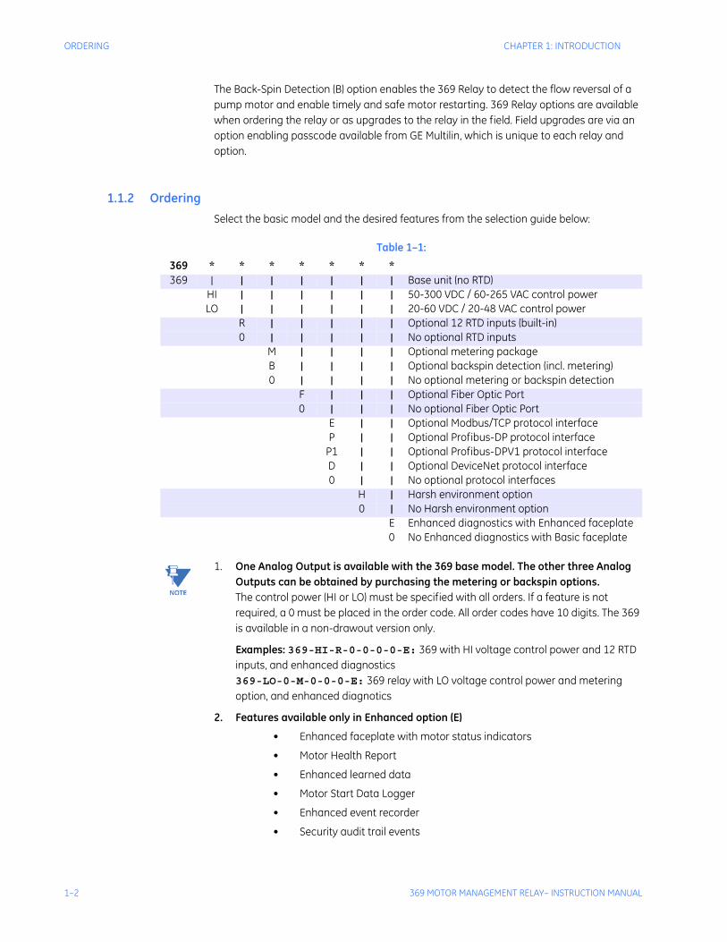
1.1.2 OrderingSelect the basic model and the desired features from the selection guide below:
NoteNotes: 1. One Analog Output is available with the 369 base model. The other three Analog Outputs can be obtained by purchasing the metering or backspin options.The control power (HI or LO) must be specified with all orders. If a feature is not required, a 0 must be placed in the order code. All order codes have 10 digits. The 369 is available in a non-drawout version only.
Examples: 369-HI-R-0-0-0-0-E: 369 with HI voltage control power and 12 RTD inputs, and enhanced diagnostics369-LO-0-M-0-0-0-E: 369 relay with LO voltage control power and metering option, and enhanced diagnotics
2. Features available only in Enhanced option (E)
• Enhanced faceplate with motor status indicators
• Motor Health Report
• Enhanced learned data
• Motor Start Data Logger
• Enhanced event recorder
• Security audit trail events
Table 1–1:
369 * * * * * * *369 | | | | | | | Base unit (no RTD)
HI | | | | | | 50-300 VDC / 60-265 VAC control powerLO | | | | | | 20-60 VDC / 20-48 VAC control power
R | | | | | Optional 12 RTD inputs (built-in)0 | | | | | No optional RTD inputs
M | | | | Optional metering packageB | | | | Optional backspin detection (incl. metering)0 | | | | No optional metering or backspin detection
F | | | Optional Fiber Optic Port0 | | | No optional Fiber Optic Port
E | | Optional Modbus/TCP protocol interfaceP | | Optional Profibus-DP protocol interface
P1 | | Optional Profibus-DPV1 protocol interfaceD | | Optional DeviceNet protocol interface0 | | No optional protocol interfaces
H | Harsh environment option 0 | No Harsh environment option
E Enhanced diagnostics with Enhanced faceplate0 No Enhanced diagnostics with Basic faceplate
CHAPTER 1: INTRODUCTION ORDERING
369 MOTOR MANAGEMENT RELAY– INSTRUCTION MANUAL 1–3
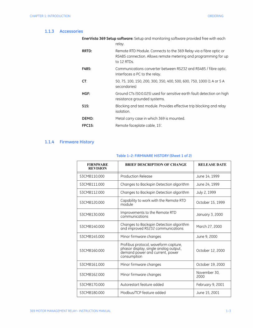
1.1.3 AccessoriesEnerVista 369 Setup software: Setup and monitoring software provided free with each
relay.
RRTD: Remote RTD Module. Connects to the 369 Relay via a fibre optic or RS485 connection. Allows remote metering and programming for up to 12 RTDs.
F485: Communications converter between RS232 and RS485 / fibre optic. Interfaces a PC to the relay.
CT: 50, 75, 100, 150, 200, 300, 350, 400, 500, 600, 750, 1000 (1 A or 5 A secondaries)
HGF: Ground CTs (50:0.025) used for sensitive earth fault detection on high resistance grounded systems.
515: Blocking and test module. Provides effective trip blocking and relay isolation.
DEMO: Metal carry case in which 369 is mounted.
FPC15: Remote faceplate cable, 15'.
1.1.4 Firmware History
Table 1–2: FIRMWARE HISTORY (Sheet 1 of 2)
FIRMWARE REVISION
BRIEF DESCRIPTION OF CHANGE RELEASE DATE
53CMB110.000 Production Release June 14, 1999
53CMB111.000 Changes to Backspin Detection algorithm June 24, 1999
53CMB112.000 Changes to Backspin Detection algorithm July 2, 1999
53CMB120.000 Capability to work with the Remote RTD module October 15, 1999
53CMB130.000 Improvements to the Remote RTD communications January 3, 2000
53CMB140.000 Changes to Backspin Detection algorithm and improved RS232 communications March 27, 2000
53CMB145.000 Minor firmware changes June 9, 2000
53CMB160.000Profibus protocol, waveform capture, phasor display, single analog output, demand power and current, power consumption
October 12, 2000
53CMB161.000 Minor firmware changes October 19, 2000
53CMB162.000 Minor firmware changes November 30, 2000
53CMB170.000 Autorestart feature added February 9, 2001
53CMB180.000 Modbus/TCP feature added June 15, 2001
1–4 369 MOTOR MANAGEMENT RELAY– INSTRUCTION MANUAL
ORDERING CHAPTER 1: INTRODUCTION
1.1.5 PC Program (Software) History
53CMB190.000 Number of Event Recorders increased to 250; Hottest Overall RTD value added
November 23, 2001
53CMB201.000Added Starter Failure, MWhrs as analog output parameter, and Motor Load Averaging feature.
April 16, 2004
53CMB210.000 Added support for variable frequency drives; minor changes to Modbus TCP. November 5, 2004
53CMB220.000 Implementation of DeviceNet protocol and starter operation monitor. April 11, 2005
53CMB230.000 Implemented Profibus DPV1, Force Outputs and Protection Blocking.
September 19, 2005
53CMB240.000 Custom Curve enhancement, increase range from 0 to 32767 to 0 to 65534.
November 21, 2005
53CMB250.000
Implementation of start control relay timer setting for reduced voltage starting, additional Modbus address added for starts/hour lockout time remaining, correction to date and time Broadcast command Modbus addresses, fix for latched resets with multiple local/remote assigned relays, fix for repeated “Motor Stopped” and “Motor Running” events.
April 28, 2006
53CMC310.000
Profibus loss of trip, trip contact seal in undervoltage auto restart, Motor Health Report, Enhanced learned data, motor start data logger, enhanced event recorder, security audit trail events, DeviceNet enhanced polling.
June 7, 2007
53CMC320.0002-speed motor feature, Datalogger feature, speed of last trip display, latched trip and alarm note.
March 20, 2008
53CMC330.000 Added Ethernet Loss of Comms Trip. May 7, 2009
53CMC340.000 Added DeviceNet Loss of Comms Trip. July 7, 2010
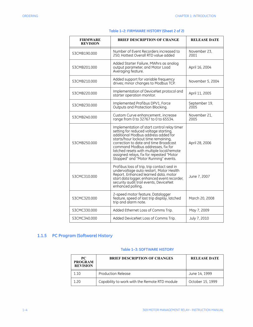
Table 1–2: FIRMWARE HISTORY (Sheet 2 of 2)
FIRMWARE REVISION
BRIEF DESCRIPTION OF CHANGE RELEASE DATE
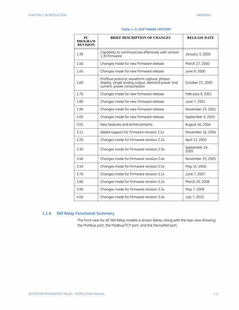
Table 1–3: SOFTWARE HISTORY
PC PROGRAM REVISION
BRIEF DESCRIPTION OF CHANGES RELEASE DATE
1.10 Production Release June 14, 1999
1.20 Capability to work with the Remote RTD module October 15, 1999
CHAPTER 1: INTRODUCTION ORDERING
369 MOTOR MANAGEMENT RELAY– INSTRUCTION MANUAL 1–5
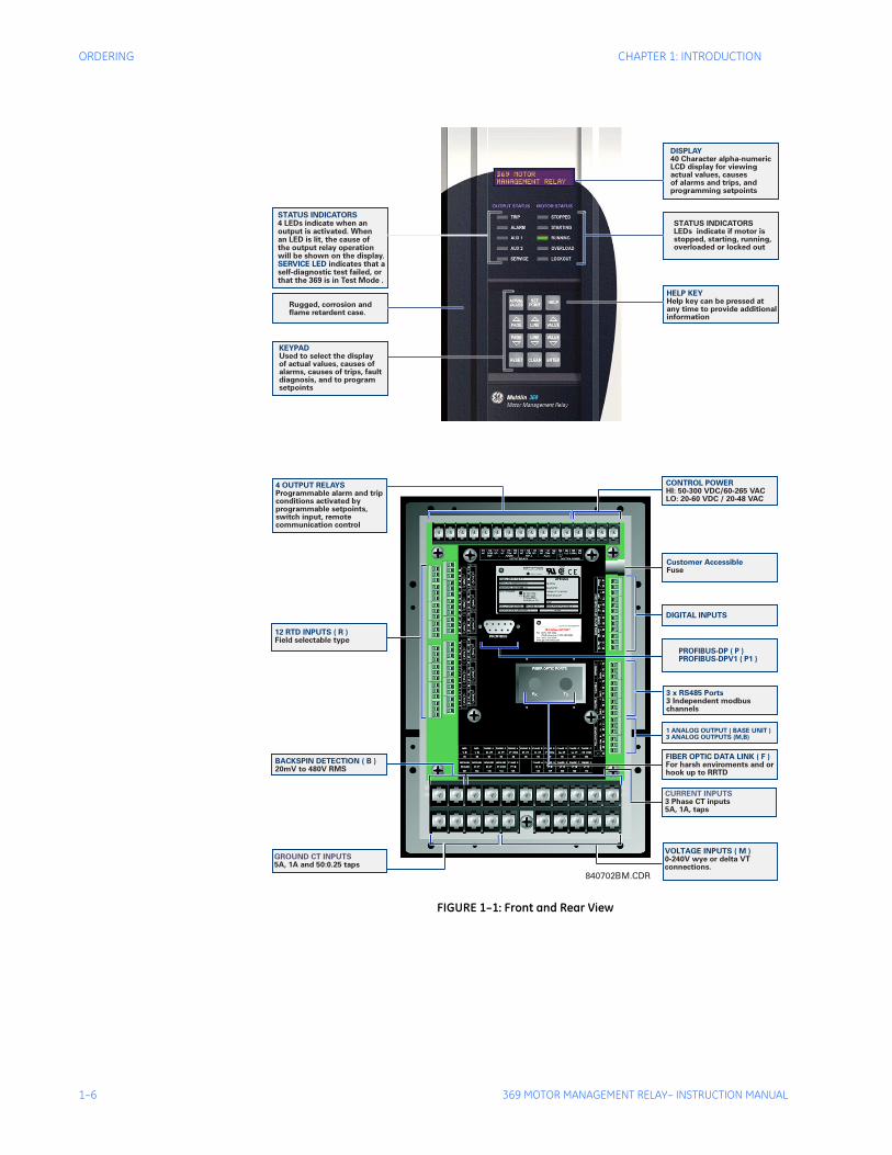
1.1.6 369 Relay Functional SummaryThe front view for all 369 Relay models is shown below, along with the rear view showing the Profibus port, the Modbus/TCP port, and the DeviceNet port.
1.30 Capability to communicate effectively with version 1.30 firmware January 3, 2000
1.40 Changes made for new firmware release March 27, 2000
1.45 Changes made for new firmware release June 9, 2000
1.60Profibus protocol, waveform capture, phasor display, single analog output, demand power and current, power consumption
October 23, 2000
1.70 Changes made for new firmware release February 9, 2001
1.80 Changes made for new firmware release June 7, 2001
1.90 Changes made for new firmware release November 23, 2001
2.00 Changes made for new firmware release September 9, 2003
3.01 New features and enhancements August 16, 2004
3.11 Added support for firmware revision 2.1x November 16, 2004
3.20 Changes made for firmware revision 2.2x April 13, 2005
3.30 Changes made for firmware revision 2.3x September 19, 2005
3.40 Changes made for firmware revision 2.4x November 25, 2005
3.50 Changes made for firmware revision 2.5x May 15, 2006
3.70 Changes made for firmware revision 3.1x June 7, 2007
3.80 Changes made for firmware revision 3.2x March 20, 2008
3.90 Changes made for firmware revision 3.3x May 7, 2009
4.00 Changes made for firmware revision 3.4x July 7, 2010
Table 1–3: SOFTWARE HISTORY
PC PROGRAM REVISION
BRIEF DESCRIPTION OF CHANGES RELEASE DATE
1–6 369 MOTOR MANAGEMENT RELAY– INSTRUCTION MANUAL
ORDERING CHAPTER 1: INTRODUCTION
FIGURE 1–1: Front and Rear View
840702BM.CDR
FIBER OPTIC DATA LINK ( F )For harsh enviroments and orhook up to RRTD
PROFIBUS-DP ( P )PROFIBUS-DPV1 ( P1 )
BACKSPIN DETECTION ( B )20mV to 480V RMS
3 x RS485 Ports3 Independent modbuschannels
1 ANALOG OUTPUT ( BASE UNIT )3 ANALOG OUTPUTS (M,B)
VOLTAGE INPUTS ( M )0-240V wye or delta VTconnections.
GROUND CT INPUTS5A, 1A and 50:0.25 taps
12 RTD INPUTS ( R )Field selectable type
CURRENT INPUTS3 Phase CT inputs5A, 1A, taps
CONTROL POWERHI: 50-300 VDC/60-265 VACLO: 20-60 VDC / 20-48 VAC
4 OUTPUT RELAYSProgrammable alarm and tripconditions activated byprogrammable setpoints,switch input, remotecommunication control
Customer AccessibleFuse
DIGITAL INPUTS
DISPLAY40 Character alpha-numericLCD display for viewingactual values, causesof alarms and trips, andprogramming setpoints
STATUS INDICATORSLEDs indicate if motor isstopped, starting, running,overloaded or locked out
HELP KEYHelp key can be pressed atany time to provide additionalinformation
KEYPADUsed to select the displayof actual values, causes ofalarms, causes of trips, faultdiagnosis, and to programsetpoints
Rugged, corrosion andflame retardent case.
STATUS INDICATORS
SERVICE LED
4 LEDs indicate when anoutput is activated. Whenan LED is lit, the cause ofthe output relay operationwill be shown on the display.
indicates that aself-diagnostic test failed, orthat the 369 is in Test Mode .
6
320
CHAPTER 1: INTRODUCTION ORDERING
369 MOTOR MANAGEMENT RELAY– INSTRUCTION MANUAL 1–7
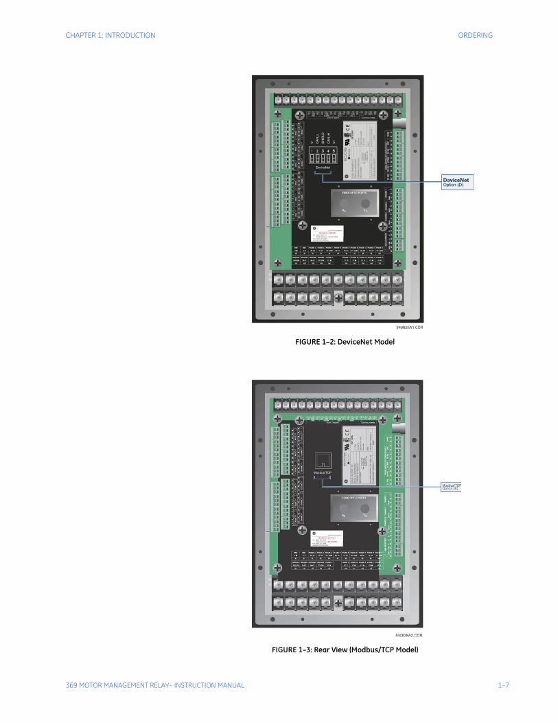
FIGURE 1–2: DeviceNet Model
FIGURE 1–3: Rear View (Modbus/TCP Model)
1–8 369 MOTOR MANAGEMENT RELAY– INSTRUCTION MANUAL
ORDERING CHAPTER 1: INTRODUCTION
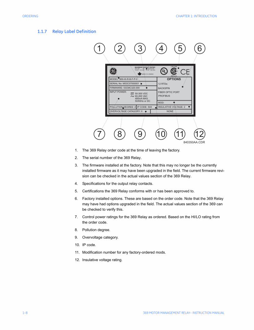
1.1.7 Relay Label Definition
1. The 369 Relay order code at the time of leaving the factory.
2. The serial number of the 369 Relay.
3. The firmware installed at the factory. Note that this may no longer be the currently installed firmware as it may have been upgraded in the field. The current firmware revi-sion can be checked in the actual values section of the 369 Relay.
4. Specifications for the output relay contacts.
5. Certifications the 369 Relay conforms with or has been approved to.
6. Factory installed options. These are based on the order code. Note that the 369 Relay may have had options upgraded in the field. The actual values section of the 369 can be checked to verify this.
7. Control power ratings for the 369 Relay as ordered. Based on the HI/LO rating from the order code.
8. Pollution degree.
9. Overvoltage category.
10. IP code.
11. Modification number for any factory-ordered mods.
12. Insulative voltage rating.
CEg
INPUT POWER:
MODEL: 369-HI-R-B-F-P-0
MAXIMUM CONTACT RATING250 VAC 8A RESISTIVE
1/4 HP 125 VAC 1/2 HP 250 VAC
SERIAL No: M53C07000001
FIRMWARE: 53CMC320.000
POLLUTION DEGREE: 2 IP CODE: 50X
50-300 VDC
60-265 VAC
485mA MAX.
50/60Hz or DCMOD:
12 RTDs:
BACKSPIN
FIBER OPTIC PORT
PROFIBUS
OPTIONS
INSULATIVE VOLTAGE: 2
NONEOVERVOLTAGE CATAGORY: II
1
7
2
8
3
9
4
10 11
5 6
12840350AA.CDR
UL
369 MOTOR MANAGEMENT RELAY– INSTRUCTION MANUAL 2–9
369 Motor Management Relay
Chapter 2: Product Description
Digital EnergyMultilin
Product Description
2.1 Overview
2.1.1 Guideform SpecificationsMotor protection and management shall be provided by a digital relay. Protective func-tions include:
• phase overload standard curves (51)
• overload by custom programmable curve (51)
• I2t modeling (49)
• current unbalance / single phase detection (46)
• starts per hour and time between starts
• short circuit (50)
• ground fault (50G/50N 51G/51N)
• mechanical jam / stall
• two-speed motor protection
Optional functions include:
• under / overvoltage (27/59)
• phase reversal (47)
• underpower (37)
• power factor (55)
• stator / bearing overtemperature with twelve (12) independent RTD inputs (49/38)
• backspin detection
Management functions include:
• statistical data
2–10 369 MOTOR MANAGEMENT RELAY– INSTRUCTION MANUAL
OVERVIEWCHAPTER 2: PRODUCT DESCRIPTION
• pre-trip data (last 40 events)
• ability to learn, display and integrate critical parameters to maximize motor protection
• a keypad with 40 character display
• flash memory
The relay is capable of displaying important metering functions, including phase volt-ages, kilowatts, kvars, power factor, frequency and MWhr. In addition, undervoltageand low power factor alarm and trip levels are field programmable. The communica-tions interface include one front RS232 port and three independent rear RS485 portswith supporting PC software, thus allowing easy setpoint programming, local retrievalof information and flexibility in communication with SCADA and engineering worksta-tions.
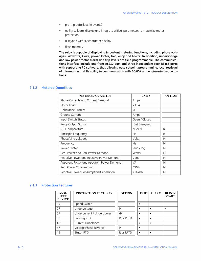
2.1.2 Metered Quantities
2.1.3 Protection Features
METERED QUANTITY UNITS OPTIONPhase Currents and Current Demand AmpsMotor Load × FLAUnbalance Current %Ground Current AmpsInput Switch Status Open / ClosedRelay Output Status (De) EnergizedRTD Temperature °C or °F RBackspin Frequency Hz BPhase/Line Voltages Volts MFrequency Hz MPower Factor lead / lag MReal Power and Real Power Demand Watts MReactive Power and Reactive Power Demand Vars MApparent Power and Apparent Power Demand VA MReal Power Consumption MWh MReactive Power Consumption/Generation ±Mvarh M
ANSI/IEEE
DEVICE
PROTECTION FEATURES OPTION TRIP ALARM BLOCKSTART
14 Speed Switch •27 Undervoltage M • • •37 Undercurrent / Underpower /M • •38 Bearing RTD R or RRTD • •46 Current Unbalance • •47 Voltage Phase Reversal M •49 Stator RTD R or RRTD • •
CHAPTER 2: PRODUCT DESCRIPTIONOVERVIEW
369 MOTOR MANAGEMENT RELAY– INSTRUCTION MANUAL 2–11
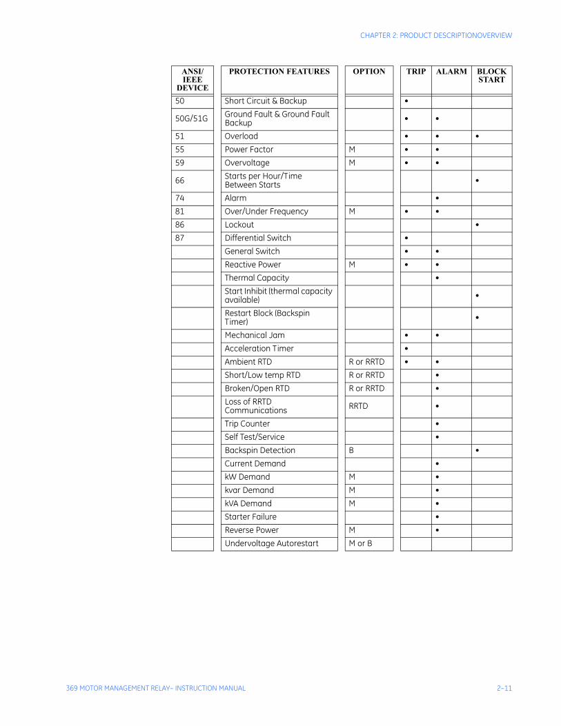
50 Short Circuit & Backup •
50G/51G Ground Fault & Ground Fault Backup • •
51 Overload • • •55 Power Factor M • •59 Overvoltage M • •
66 Starts per Hour/Time Between Starts •
74 Alarm •81 Over/Under Frequency M • •86 Lockout •87 Differential Switch •
General Switch • •Reactive Power M • •Thermal Capacity •Start Inhibit (thermal capacity available) •
Restart Block (Backspin Timer) •
Mechanical Jam • •Acceleration Timer •Ambient RTD R or RRTD • •Short/Low temp RTD R or RRTD •Broken/Open RTD R or RRTD •Loss of RRTD Communications RRTD •
Trip Counter •Self Test/Service •Backspin Detection B •Current Demand •kW Demand M •kvar Demand M •kVA Demand M •Starter Failure •Reverse Power M •Undervoltage Autorestart M or B
ANSI/IEEE
DEVICE
PROTECTION FEATURES OPTION TRIP ALARM BLOCKSTART
2–12 369 MOTOR MANAGEMENT RELAY– INSTRUCTION MANUAL
OVERVIEWCHAPTER 2: PRODUCT DESCRIPTION
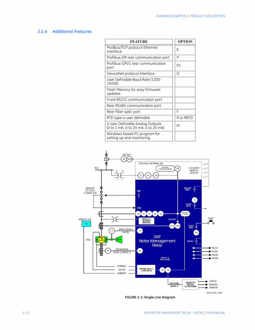
2.1.4 Additional Features
FIGURE 2–1: Single Line Diagram
FEATURE OPTIONModbus/TCP protocol Ethernet interface E
Profibus-DP rear communication port PProfibus-DPV1 rear communication port P1
DeviceNet protocol interface DUser Definable Baud Rate (1200-19200)Flash Memory for easy firmware updatesFront RS232 communication portRear RS485 communication portRear fiber optic port FRTD type is user definable R or RRTD4 User Definable Analog Outputs(0 to 1 mA, 0 to 20 mA, 4 to 20 mA) M
Windows based PC program for setting up and monitoring
CHAPTER 2: PRODUCT DESCRIPTIONSPECIFICATIONS
369 MOTOR MANAGEMENT RELAY– INSTRUCTION MANUAL 2–13
2.2 Specifications
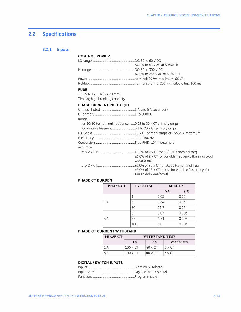
2.2.1 InputsCONTROL POWERLO range:............................................................DC: 20 to 60 V DC
AC: 20 to 48 V AC at 50/60 HzHI range: .............................................................DC: 50 to 300 V DC
AC: 60 to 265 V AC at 50/60 HzPower:..................................................................nominal: 20 VA; maximum: 65 VAHoldup:................................................................non-failsafe trip: 200 ms; failsafe trip: 100 ms
FUSET 3.15 A H 250 V (5 × 20 mm)Timelag high breaking capacity
PHASE CURRENT INPUTS (CT)CT input (rated): ...............................................1 A and 5 A secondaryCT primary: ........................................................1 to 5000 ARange:
for 50/60 Hz nominal frequency: ......0.05 to 20 × CT primary ampsfor variable frequency: ...........................0.1 to 20 × CT primary amps
Full Scale: ...........................................................20 × CT primary amps or 65535 A maximumFrequency: .........................................................20 to 100 HzConversion: .......................................................True RMS, 1.04 ms/sampleAccuracy:
at ≤ 2 × CT: ....................................................±0.5% of 2 × CT for 50/60 Hz nominal freq.±1.0% of 2 × CT for variable frequency (for sinusoidal waveforms)
at > 2 × CT: ....................................................±1.0% of 20 × CT for 50/60 Hz nominal freq.±3.0% of 12 × CT or less for variable frequency (for sinusoidal waveforms)
PHASE CT BURDEN
PHASE CT CURRENT WITHSTAND
DIGITAL / SWITCH INPUTSInputs: ..................................................................6 optically isolatedInput type:..........................................................Dry Contact (< 800 Ω)Function:.............................................................Programmable
PHASE CT INPUT (A) BURDENVA (Ω)
1 A1 0.03 0.035 0.64 0.0320 11.7 0.03
5 A5 0.07 0.00325 1.71 0.003100 31 0.003
PHASE CT WITHSTAND TIME 1 s 2 s continuous
1 A 100 × CT 40 × CT 3 × CT5 A 100 × CT 40 × CT 3 × CT
2–14 369 MOTOR MANAGEMENT RELAY– INSTRUCTION MANUAL
SPECIFICATIONSCHAPTER 2: PRODUCT DESCRIPTION
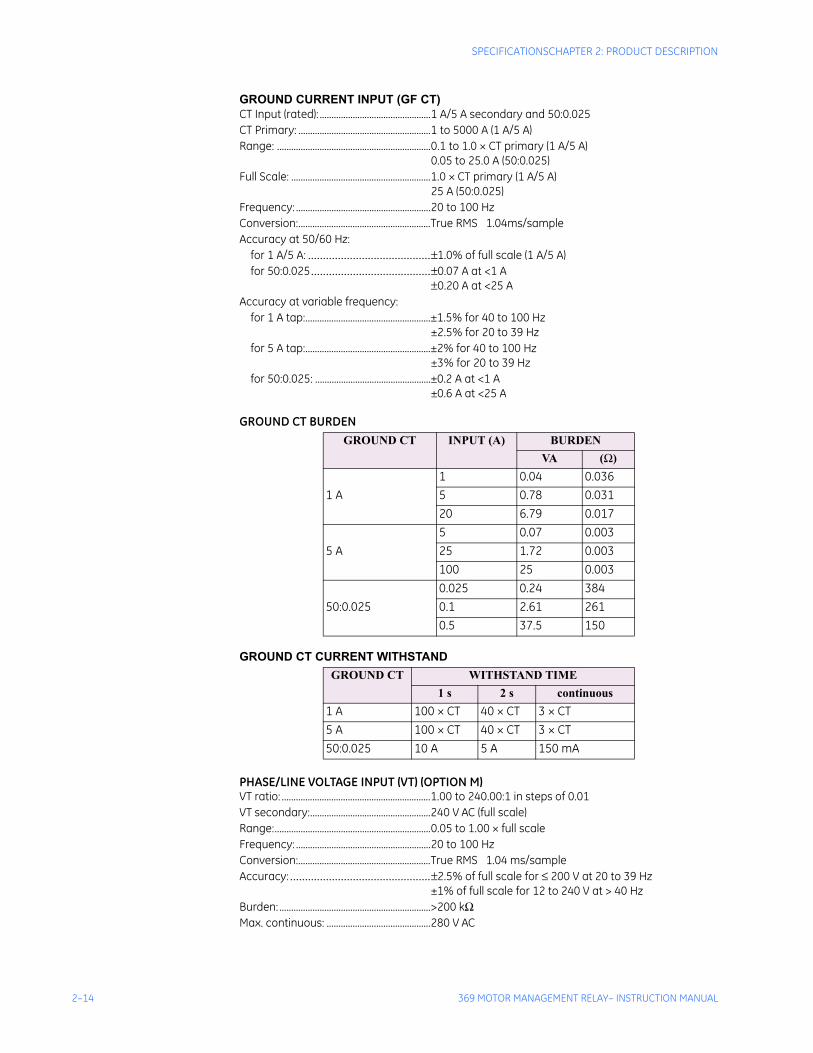
GROUND CURRENT INPUT (GF CT)CT Input (rated): ...............................................1 A/5 A secondary and 50:0.025CT Primary: ........................................................1 to 5000 A (1 A/5 A)Range: .................................................................0.1 to 1.0 × CT primary (1 A/5 A)
0.05 to 25.0 A (50:0.025)Full Scale: ...........................................................1.0 × CT primary (1 A/5 A)
25 A (50:0.025)Frequency: .........................................................20 to 100 HzConversion:........................................................True RMS 1.04ms/sampleAccuracy at 50/60 Hz:
for 1 A/5 A: .........................................±1.0% of full scale (1 A/5 A)for 50:0.025........................................±0.07 A at <1 A
±0.20 A at <25 AAccuracy at variable frequency:
for 1 A tap:.....................................................±1.5% for 40 to 100 Hz±2.5% for 20 to 39 Hz
for 5 A tap:.....................................................±2% for 40 to 100 Hz±3% for 20 to 39 Hz
for 50:0.025: .................................................±0.2 A at <1 A±0.6 A at <25 A
GROUND CT BURDEN
GROUND CT CURRENT WITHSTAND
PHASE/LINE VOLTAGE INPUT (VT) (OPTION M)VT ratio: ...............................................................1.00 to 240.00:1 in steps of 0.01VT secondary:...................................................240 V AC (full scale)Range:..................................................................0.05 to 1.00 × full scaleFrequency: .........................................................20 to 100 HzConversion:........................................................True RMS 1.04 ms/sampleAccuracy: ...............................................±2.5% of full scale for ≤ 200 V at 20 to 39 Hz
±1% of full scale for 12 to 240 V at > 40 HzBurden: ................................................................>200 kΩMax. continuous: ............................................280 V AC
GROUND CT INPUT (A) BURDENVA (Ω)
1 A 1 0.04 0.0365 0.78 0.03120 6.79 0.017
5 A 5 0.07 0.00325 1.72 0.003100 25 0.003
50:0.0250.025 0.24 3840.1 2.61 2610.5 37.5 150
GROUND CT WITHSTAND TIME1 s 2 s continuous
1 A 100 × CT 40 × CT 3 × CT5 A 100 × CT 40 × CT 3 × CT50:0.025 10 A 5 A 150 mA
CHAPTER 2: PRODUCT DESCRIPTIONSPECIFICATIONS
369 MOTOR MANAGEMENT RELAY– INSTRUCTION MANUAL 2–15
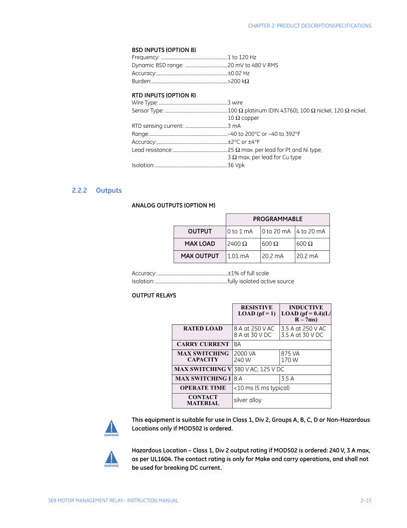
BSD INPUTS (OPTION B)Frequency: ........................................................1 to 120 HzDynamic BSD range: ....................................20 mV to 480 V RMSAccuracy: ...............................................±0.02 HzBurden:................................................................>200 kΩ
RTD INPUTS (OPTION R)Wire Type: ..........................................................3 wireSensor Type: .....................................................100 Ω platinum (DIN 43760), 100 Ω nickel, 120 Ω nickel,
10 Ω copperRTD sensing current: ....................................3 mARange:..................................................................–40 to 200°C or –40 to 392°FAccuracy: ...............................................±2°C or ±4°FLead resistance:..............................................25 Ω max. per lead for Pt and Ni type;
3 Ω max. per lead for Cu typeIsolation: .............................................................36 Vpk
2.2.2 Outputs
ANALOG OUTPUTS (OPTION M)
Accuracy: ...............................................±1% of full scaleIsolation: .............................................................fully isolated active source
OUTPUT RELAYS
This equipment is suitable for use in Class 1, Div 2, Groups A, B, C, D or Non-Hazardous Locations only if MOD502 is ordered.
Hazardous Location – Class 1, Div 2 output rating if MOD502 is ordered: 240 V, 3 A max, as per UL1604. The contact rating is only for Make and carry operations, and shall not be used for breaking DC current.
PROGRAMMABLE
OUTPUT 0 to 1 mA 0 to 20 mA 4 to 20 mA
MAX LOAD 2400 Ω 600 Ω 600 Ω
MAX OUTPUT 1.01 mA 20.2 mA 20.2 mA
RESISTIVE LOAD (pf = 1)
INDUCTIVE LOAD (pf = 0.4)(L/
R – 7ms)RATED LOAD 8 A at 250 V AC
8 A at 30 V DC3.5 A at 250 V AC3.5 A at 30 V DC
CARRY CURRENT 8AMAX SWITCHING
CAPACITY2000 VA240 W
875 VA170 W
MAX SWITCHING V 380 V AC; 125 V DCMAX SWITCHING I 8 A 3.5 A
OPERATE TIME <10 ms (5 ms typical)CONTACT
MATERIAL silver alloy
2–16 369 MOTOR MANAGEMENT RELAY– INSTRUCTION MANUAL
SPECIFICATIONSCHAPTER 2: PRODUCT DESCRIPTION
Explosion Hazard – Substitution of components may impair suitability for Class 1, Div 2.
Explosion Hazard – Do not disconnect equipment unless power has been switched off or the area is known to be Non-Hazardous.
2.2.3 Metering
POWER METERING (OPTION M)
EVENT RECORDCapacity:.............................................................last 512 eventsTriggers: ..............................................................trip, inhibit, power fail, alarms, self test,
waveform capture
WAVEFORM CAPTURELength:.................................................................3 buffers containing 16 cycles of all current and voltage
channelsTrigger position: ..............................................1 to 100% pre-trip to post-tripTrigger: ...............................................................trip, manually via communications or digital input
MOTOR START DATA LOGGERLength: ...............................................................6 Buffers containing 30 seconds of motor start data.Trigger: ...............................................................Motor Start Status.Trigger position: .............................................1-second pre-trigger duration. Logging rate: ...................................................1 sample/200ms.
PARAMETER
ACCURACY
(FULL SCALE)
RESOLUTION
RANGE
kW ±2% 1 kW ±32000kvar ±2% 1 kvar ±32000kVA ±2% 1 kVA 0 to 65000kWh ±2% 1 kWh 0 to 999MWh ±2% 1 MWh 0 to 65535±kvarh ±2% 1 kvarh 0 to 999±Mvarh ±2% 1 Mvarh 0 to 65535Power Factor ±1% 0.01 –0.99 to 1.00
Frequency ±0.02 Hz 0.01 Hz 20.00 to 100.00
kW Demand ±2% 1 kW 0 to 32000kvar Demand ±2% 1 kvar 0 to 32000kVA Demand ±2% 1 kVA 0 to 65000Amp Demand ±2% 1 A 0 to 65535

CHAPTER 2: PRODUCT DESCRIPTIONSPECIFICATIONS
369 MOTOR MANAGEMENT RELAY– INSTRUCTION MANUAL 2–17
2.2.4 Communications
FRONT PORTType: .....................................................................RS232, non-isolatedBaud rate: ..........................................................4800 to 19200Protocol:..............................................................Modbus® RTU
BACK PORTS (3)Type: .....................................................................RS485Baud rate: ..........................................................1200 to 19200Protocol:..............................................................Modbus® RTU36V isolation (together)
PROFIBUS (OPTIONS P AND P1)Type: .....................................................................RS485Baud rate: ..........................................................1200 baud to 12 MbaudProtocol:..............................................................Profibus-DP
Profibus-DPV1Connector Type:..............................................DB9 Female
MODBUS/TCP ETHERNET (OPTION E)Connector type:...............................................RJ45Protocol:..............................................................Modbus/TCP
DEVICENET (OPTION D)DeviceNet CONFORMANCE TESTED™
Connector type:...............................................5-pin linear DeviceNet plug (phoenix type)Baud rate: ..........................................................125, 250, and 500 kbpsProtocol:..............................................................DeviceNetBus-Side Current Draw:...............................85mA (Typical), 100mA (Max)
FIBER OPTIC PORT (OPTION F)Optional use:.....................................................RTD remote module hookupBaud rate: ..........................................................1200 to 19200Protocol:..............................................................Modbus® RTUFiber sizes: .........................................................50/125, 62.5/125, 100/140, and 200 μmEmitter fiber type: ..........................................820 nm LED, multimodeLink power budget:Transmit power: ...........................................–20 dBmReceived sensitivity: ...................................–30 dBmPower budget: ...............................................10 dB
Maximum optical input power: ..............–7.6 dBmTypical link distance: ...................................1.65 km
Note Typical link distance is based upon the following assumptions for system loss. As actual losses vary between installations, the distance covered will vary.
Connector loss: ..............................................2 dBFiber loss: ..........................................................3 dB/kmSplice loss: ........................................................One splice every 2 km at 0.05 dB loss/spliceSystem margin: ..............................................3 dB additional loss added to calculations to compensate
for all other losses
2–18 369 MOTOR MANAGEMENT RELAY– INSTRUCTION MANUAL
SPECIFICATIONSCHAPTER 2: PRODUCT DESCRIPTION
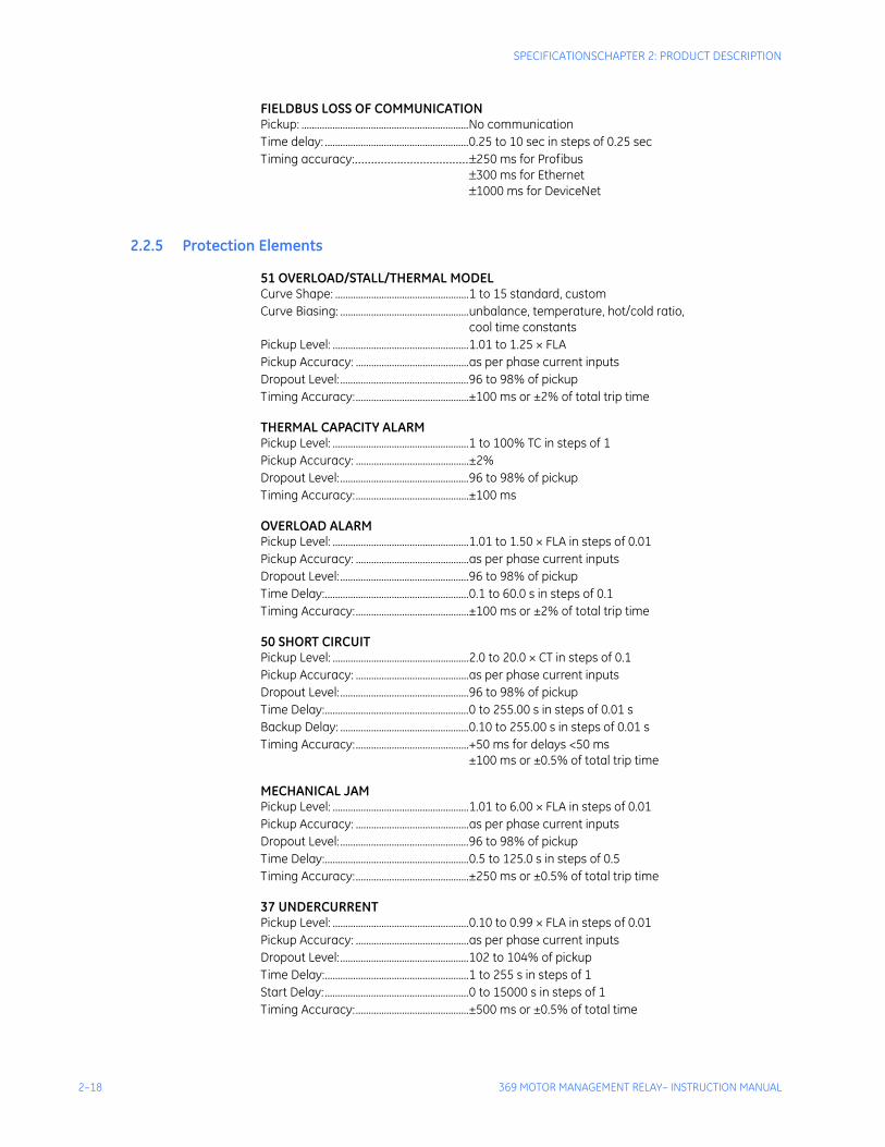
FIELDBUS LOSS OF COMMUNICATIONPickup: .................................................................No communicationTime delay: ........................................................0.25 to 10 sec in steps of 0.25 secTiming accuracy:...................................±250 ms for Profibus
±300 ms for Ethernet±1000 ms for DeviceNet
2.2.5 Protection Elements
51 OVERLOAD/STALL/THERMAL MODELCurve Shape: ....................................................1 to 15 standard, customCurve Biasing: ..................................................unbalance, temperature, hot/cold ratio,
cool time constantsPickup Level: .....................................................1.01 to 1.25 × FLAPickup Accuracy: ............................................as per phase current inputsDropout Level:..................................................96 to 98% of pickupTiming Accuracy:............................................±100 ms or ±2% of total trip time
THERMAL CAPACITY ALARMPickup Level: .....................................................1 to 100% TC in steps of 1Pickup Accuracy: ............................................±2%Dropout Level:..................................................96 to 98% of pickupTiming Accuracy:............................................±100 ms
OVERLOAD ALARMPickup Level: .....................................................1.01 to 1.50 × FLA in steps of 0.01Pickup Accuracy: ............................................as per phase current inputsDropout Level:..................................................96 to 98% of pickupTime Delay:........................................................0.1 to 60.0 s in steps of 0.1Timing Accuracy:............................................±100 ms or ±2% of total trip time
50 SHORT CIRCUITPickup Level: .....................................................2.0 to 20.0 × CT in steps of 0.1Pickup Accuracy: ............................................as per phase current inputsDropout Level:..................................................96 to 98% of pickupTime Delay:........................................................0 to 255.00 s in steps of 0.01 sBackup Delay: ..................................................0.10 to 255.00 s in steps of 0.01 sTiming Accuracy:............................................+50 ms for delays <50 ms
±100 ms or ±0.5% of total trip time
MECHANICAL JAMPickup Level: .....................................................1.01 to 6.00 × FLA in steps of 0.01Pickup Accuracy: ............................................as per phase current inputsDropout Level:..................................................96 to 98% of pickupTime Delay:........................................................0.5 to 125.0 s in steps of 0.5Timing Accuracy:............................................±250 ms or ±0.5% of total trip time
37 UNDERCURRENTPickup Level: .....................................................0.10 to 0.99 × FLA in steps of 0.01Pickup Accuracy: ............................................as per phase current inputsDropout Level:..................................................102 to 104% of pickupTime Delay:........................................................1 to 255 s in steps of 1Start Delay:........................................................0 to 15000 s in steps of 1Timing Accuracy:............................................±500 ms or ±0.5% of total time
CHAPTER 2: PRODUCT DESCRIPTIONSPECIFICATIONS
369 MOTOR MANAGEMENT RELAY– INSTRUCTION MANUAL 2–19
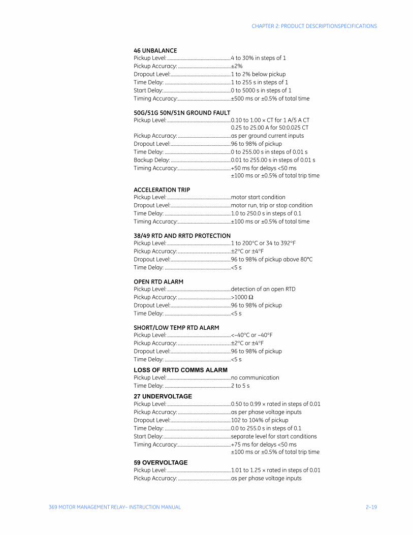
46 UNBALANCEPickup Level: .....................................................4 to 30% in steps of 1Pickup Accuracy: ............................................±2%Dropout Level:..................................................1 to 2% below pickupTime Delay: .......................................................1 to 255 s in steps of 1Start Delay:........................................................0 to 5000 s in steps of 1Timing Accuracy:............................................±500 ms or ±0.5% of total time
50G/51G 50N/51N GROUND FAULTPickup Level: .....................................................0.10 to 1.00 × CT for 1 A/5 A CT
0.25 to 25.00 A for 50:0.025 CTPickup Accuracy: ............................................as per ground current inputsDropout Level:..................................................96 to 98% of pickupTime Delay: .......................................................0 to 255.00 s in steps of 0.01 sBackup Delay: ..................................................0.01 to 255.00 s in steps of 0.01 sTiming Accuracy:............................................+50 ms for delays <50 ms
±100 ms or ±0.5% of total trip time
ACCELERATION TRIPPickup Level: .....................................................motor start conditionDropout Level:..................................................motor run, trip or stop conditionTime Delay: .......................................................1.0 to 250.0 s in steps of 0.1Timing Accuracy:............................................±100 ms or ±0.5% of total time
38/49 RTD AND RRTD PROTECTIONPickup Level: .....................................................1 to 200°C or 34 to 392°FPickup Accuracy: ...................................±2°C or ±4°FDropout Level:..................................................96 to 98% of pickup above 80°CTime Delay: .......................................................<5 s
OPEN RTD ALARMPickup Level: .....................................................detection of an open RTDPickup Accuracy: ............................................>1000 ΩDropout Level:..................................................96 to 98% of pickupTime Delay: .......................................................<5 s
SHORT/LOW TEMP RTD ALARMPickup Level: .....................................................<–40°C or –40°FPickup Accuracy: ...................................±2°C or ±4°FDropout Level:..................................................96 to 98% of pickupTime Delay: .......................................................<5 s
LOSS OF RRTD COMMS ALARMPickup Level: .....................................................no communicationTime Delay: .......................................................2 to 5 s
27 UNDERVOLTAGEPickup Level: .....................................................0.50 to 0.99 × rated in steps of 0.01Pickup Accuracy: ............................................as per phase voltage inputsDropout Level:..................................................102 to 104% of pickupTime Delay: .......................................................0.0 to 255.0 s in steps of 0.1Start Delay:........................................................separate level for start conditionsTiming Accuracy:............................................+75 ms for delays <50 ms
±100 ms or ±0.5% of total trip time
59 OVERVOLTAGEPickup Level: .....................................................1.01 to 1.25 × rated in steps of 0.01Pickup Accuracy: ............................................as per phase voltage inputs
2–20 369 MOTOR MANAGEMENT RELAY– INSTRUCTION MANUAL
SPECIFICATIONSCHAPTER 2: PRODUCT DESCRIPTION
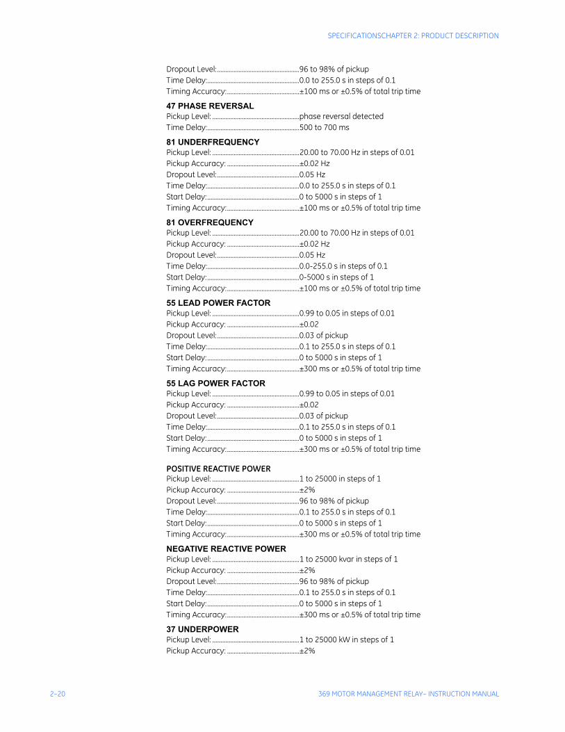
Dropout Level:..................................................96 to 98% of pickupTime Delay:........................................................0.0 to 255.0 s in steps of 0.1Timing Accuracy:............................................±100 ms or ±0.5% of total trip time
47 PHASE REVERSALPickup Level: .....................................................phase reversal detectedTime Delay:........................................................500 to 700 ms
81 UNDERFREQUENCYPickup Level: .....................................................20.00 to 70.00 Hz in steps of 0.01Pickup Accuracy: ............................................±0.02 HzDropout Level:..................................................0.05 HzTime Delay:........................................................0.0 to 255.0 s in steps of 0.1Start Delay:........................................................0 to 5000 s in steps of 1Timing Accuracy:............................................±100 ms or ±0.5% of total trip time
81 OVERFREQUENCYPickup Level: .....................................................20.00 to 70.00 Hz in steps of 0.01Pickup Accuracy: ............................................±0.02 HzDropout Level:..................................................0.05 HzTime Delay:........................................................0.0-255.0 s in steps of 0.1Start Delay:........................................................0-5000 s in steps of 1Timing Accuracy:............................................±100 ms or ±0.5% of total trip time
55 LEAD POWER FACTORPickup Level: .....................................................0.99 to 0.05 in steps of 0.01Pickup Accuracy: ............................................±0.02Dropout Level:..................................................0.03 of pickupTime Delay:........................................................0.1 to 255.0 s in steps of 0.1Start Delay:........................................................0 to 5000 s in steps of 1Timing Accuracy:............................................±300 ms or ±0.5% of total trip time
55 LAG POWER FACTORPickup Level: .....................................................0.99 to 0.05 in steps of 0.01Pickup Accuracy: ............................................±0.02Dropout Level:..................................................0.03 of pickupTime Delay:........................................................0.1 to 255.0 s in steps of 0.1Start Delay:........................................................0 to 5000 s in steps of 1Timing Accuracy:............................................±300 ms or ±0.5% of total trip time
POSITIVE REACTIVE POWERPickup Level: .....................................................1 to 25000 in steps of 1Pickup Accuracy: ............................................±2%Dropout Level:..................................................96 to 98% of pickupTime Delay:........................................................0.1 to 255.0 s in steps of 0.1Start Delay:........................................................0 to 5000 s in steps of 1Timing Accuracy:............................................±300 ms or ±0.5% of total trip time
NEGATIVE REACTIVE POWERPickup Level: .....................................................1 to 25000 kvar in steps of 1Pickup Accuracy: ............................................±2%Dropout Level:..................................................96 to 98% of pickupTime Delay:........................................................0.1 to 255.0 s in steps of 0.1Start Delay:........................................................0 to 5000 s in steps of 1Timing Accuracy:............................................±300 ms or ±0.5% of total trip time
37 UNDERPOWERPickup Level: .....................................................1 to 25000 kW in steps of 1Pickup Accuracy: ............................................±2%
CHAPTER 2: PRODUCT DESCRIPTIONSPECIFICATIONS
369 MOTOR MANAGEMENT RELAY– INSTRUCTION MANUAL 2–21
Dropout Level:..................................................102 to 104% of pickupTime Delay: .......................................................0.5 to 255.0 s in steps of 0.5Start Delay:........................................................0 to 15000 s in steps of 1Timing Accuracy:............................................±300 ms or ±0.5% of total trip time
REVERSE POWERPickup Level: .....................................................1 to 25000 kW in steps of 1Pickup Accuracy: ............................................±2%Dropout Level:..................................................96 to 98% of pickupTime Delay: .......................................................0.5 to 30.0 s in steps of 0.5Start Delay:........................................................0 to 50000 s in steps of 1Timing Accuracy:............................................±300 ms or ±0.5% of total trip time
87 DIFFERENTIAL SWITCHTime Delay: .......................................................<200 ms
14 SPEED SWITCHTime Delay: .......................................................0.5 to 100.0 s in steps of 0.5Timing Accuracy:............................................±200 ms or ±0.5% of total trip time
GENERAL SWITCHTime Delay: .......................................................0.1 to 5000.0 s in steps of 0.1Start Delay:........................................................0 to 5000 s in steps of 1Timing Accuracy:............................................±200 ms or ±0.5% of total trip time
DIGITAL COUNTERPickup: .................................................................on count equaling levelTime Delay: .......................................................<200 ms
BACKSPIN DETECTIONDynamic BSD:...................................................20 mV to 480 V RMSPickup Level: .....................................................3 to 120 Hz in steps of 1Dropout Level:..................................................2 to 30 Hz in steps of 1Level Accuracy: ...............................................±0.02 HzTiming Accuracy:............................................±500 ms or ±0.5% of total trip time
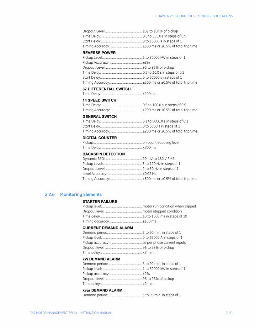
2.2.6 Monitoring ElementsSTARTER FAILUREPickup level: ......................................................motor run condition when trippedDropout level: ...................................................motor stopped conditionTime delay: ........................................................10 to 1000 ms in steps of 10Timing accuracy:............................................±100 ms
CURRENT DEMAND ALARMDemand period: ..............................................5 to 90 min. in steps of 1Pickup level: ......................................................0 to 65000 A in steps of 1Pickup accuracy: ............................................as per phase current inputsDropout level: ...................................................96 to 98% of pickupTime delay: ........................................................<2 min.
kW DEMAND ALARMDemand period: ..............................................5 to 90 min. in steps of 1Pickup level: ......................................................1 to 50000 kW in steps of 1Pickup accuracy: ............................................±2%Dropout level: ...................................................96 to 98% of pickupTime delay: ........................................................<2 min.
kvar DEMAND ALARMDemand period: ..............................................5 to 90 min. in steps of 1
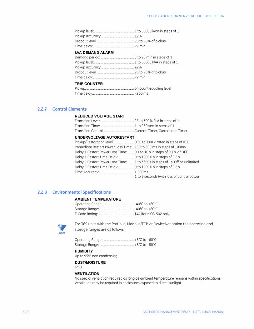
2–22 369 MOTOR MANAGEMENT RELAY– INSTRUCTION MANUAL
SPECIFICATIONSCHAPTER 2: PRODUCT DESCRIPTION
Pickup level:.......................................................1 to 50000 kvar in steps of 1Pickup accuracy:.............................................±2%Dropout level: ...................................................96 to 98% of pickupTime delay: ........................................................<2 min.
kVA DEMAND ALARMDemand period: ..............................................5 to 90 min in steps of 1Pickup level:.......................................................1 to 50000 kVA in steps of 1Pickup accuracy:.............................................±2%Dropout level: ...................................................96 to 98% of pickupTime delay: ........................................................<2 min.
TRIP COUNTERPickup: .................................................................on count equaling levelTime delay: ........................................................<200 ms
2.2.7 Control ElementsREDUCED VOLTAGE STARTTransition Level: ..............................................25 to 300% FLA in steps of 1Transition Time:...............................................1 to 250 sec. in steps of 1Transition Control:..........................................Current, Timer, Current and Timer
UNDERVOLTAGE AUTORESTARTPickup/Restoration level: ...........................0.50 to 1.00 × rated in steps of 0.01Immediate Restart Power Loss Time: ..100 to 500 ms in steps of 100msDelay 1 Restart Power Loss Time: .........0.1 to 10 s in steps of 0.1 s, or OFF.Delay 1 Restart Time Delay: .....................0 to 1200.0 s in steps of 0.2 sDelay 2 Restart Power Loss Time: ........1 to 3600s in steps of 1s, Off or UnlimitedDelay 2 Restart Time Delay: .....................0 to 1200.0 s in steps of 0.2 sTime Accuracy: ...............................................± 200ms
1 to 9 seconds (with loss of control power)
2.2.8 Environmental SpecificationsAMBIENT TEMPERATUREOperating Range: ..........................................-40°C to +60°CStorage Range: ...............................................-40°C to +80°CT-Code Rating: .................................................T4A (for MOD 502 only)
NoteNOTE: For 369 units with the Profibus, Modbus/TCP, or DeviceNet option the operating and storage ranges are as follows:
Operating Range: ..........................................+5°C to +60°CStorage Range: ...............................................+5°C to +80°C
HUMIDITYUp to 95% non condensing
DUST/MOISTUREIP50
VENTILATIONNo special ventilation required as long as ambient temperature remains within specifications. Ventilation may be required in enclosures exposed to direct sunlight.

CHAPTER 2: PRODUCT DESCRIPTIONSPECIFICATIONS
369 MOTOR MANAGEMENT RELAY– INSTRUCTION MANUAL 2–23
OVERVOLTAGE CATEGORY II
CLEANINGMay be cleaned with a damp cloth.
2–24 369 MOTOR MANAGEMENT RELAY– INSTRUCTION MANUAL
SPECIFICATIONSCHAPTER 2: PRODUCT DESCRIPTION
2.2.9 Long-term storageLONG-TERM STORAGEEnvironment: ...................................................In addition to the above environmental considerations,
the relay should be stored in an environment that is dry, corrosive-free, and not in direct sunlight.
Correct storage: ..............................................Prevents premature component failures caused by environmental factors such as moisture or corrosive gases. Exposure to high humidity or corrosive environments will prematurely degrade the electronic components in any electronic device regardless of its use or manufacturer, unless specific precautions, such as those mentioned in the Environmental section above, are taken.
Note It is recommended that all relays be powered up once per year, for one hour continuously, to avoid deterioration of electrolytic capacitors and subsequent relay failure.
2.2.10 Approvals/CertificationISO: ........................................................................Designed and manufactured to an ISO9001 registered
process.UL:..........................................................................UL Listed (File E234799*)
(File E83849)UL 508 - Industrial Control EquipmentUL 1053 - Ground Fault Protection EquipmentUL 1604* - Electrical Equipment for use in Class 1 Div 2 Hazardous Locations
CSA:.......................................................................Certified per: C22.2 No. 142 - Process Control EquipmentC22.2 No. 213* - Non-incendive Electrical Equipment for use in class 1 Div 2 Hazardous Locations
CE:..........................................................................Conforms to EN 55011/CISPR 11, EN50082-2, IEC 947-1, 1010-1
* For MOD502 only
DeviceNet CONFORMANCE TESTED™
2.2.11 Type Test StandardsSURGE WITHSTAND CAPABILITYANSI/IEEE C37.90.1 Oscillatory (2.5 kV/1 MHz)ANSI/IEEE C37.90.1 Fast Rise (5 kV/10 ns) IEC / EN 61000-4-4, Level 4
INSULATION RESISTANCEIEC / EN 60255-5
IMPULSE TESTIEC / EN 60255-5 DIELECTRIC STRENGTH: ...............................ANSI/IEEE C37.90
IEC / EN 60255-5CSA C22.2 No.14
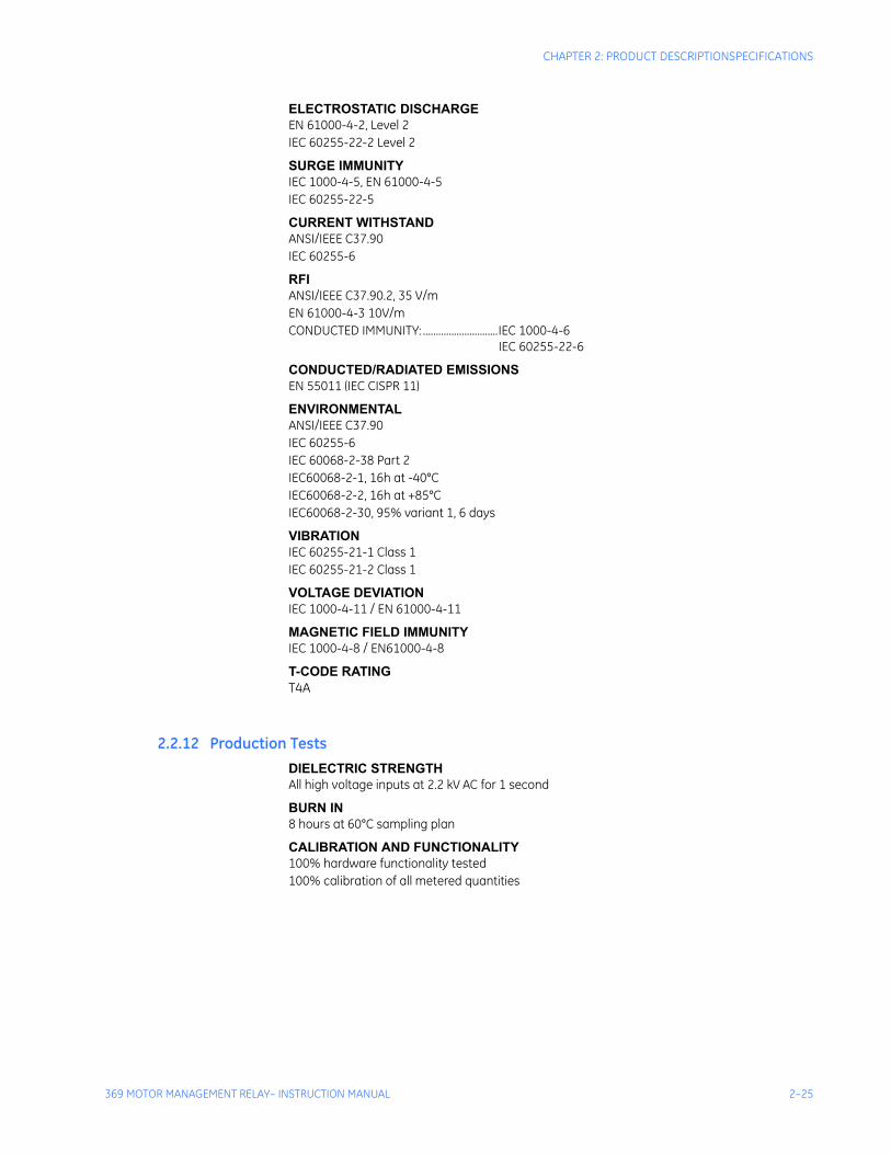
CHAPTER 2: PRODUCT DESCRIPTIONSPECIFICATIONS
369 MOTOR MANAGEMENT RELAY– INSTRUCTION MANUAL 2–25
ELECTROSTATIC DISCHARGEEN 61000-4-2, Level 2IEC 60255-22-2 Level 2
SURGE IMMUNITYIEC 1000-4-5, EN 61000-4-5IEC 60255-22-5
CURRENT WITHSTANDANSI/IEEE C37.90IEC 60255-6
RFIANSI/IEEE C37.90.2, 35 V/mEN 61000-4-3 10V/mCONDUCTED IMMUNITY: .............................IEC 1000-4-6
IEC 60255-22-6
CONDUCTED/RADIATED EMISSIONSEN 55011 (IEC CISPR 11)
ENVIRONMENTALANSI/IEEE C37.90IEC 60255-6IEC 60068-2-38 Part 2IEC60068-2-1, 16h at -40°CIEC60068-2-2, 16h at +85°CIEC60068-2-30, 95% variant 1, 6 days
VIBRATIONIEC 60255-21-1 Class 1IEC 60255-21-2 Class 1
VOLTAGE DEVIATIONIEC 1000-4-11 / EN 61000-4-11
MAGNETIC FIELD IMMUNITYIEC 1000-4-8 / EN61000-4-8
T-CODE RATINGT4A
2.2.12 Production TestsDIELECTRIC STRENGTHAll high voltage inputs at 2.2 kV AC for 1 second
BURN IN8 hours at 60°C sampling plan
CALIBRATION AND FUNCTIONALITY100% hardware functionality tested100% calibration of all metered quantities

2–26 369 MOTOR MANAGEMENT RELAY– INSTRUCTION MANUAL
SPECIFICATIONSCHAPTER 2: PRODUCT DESCRIPTION
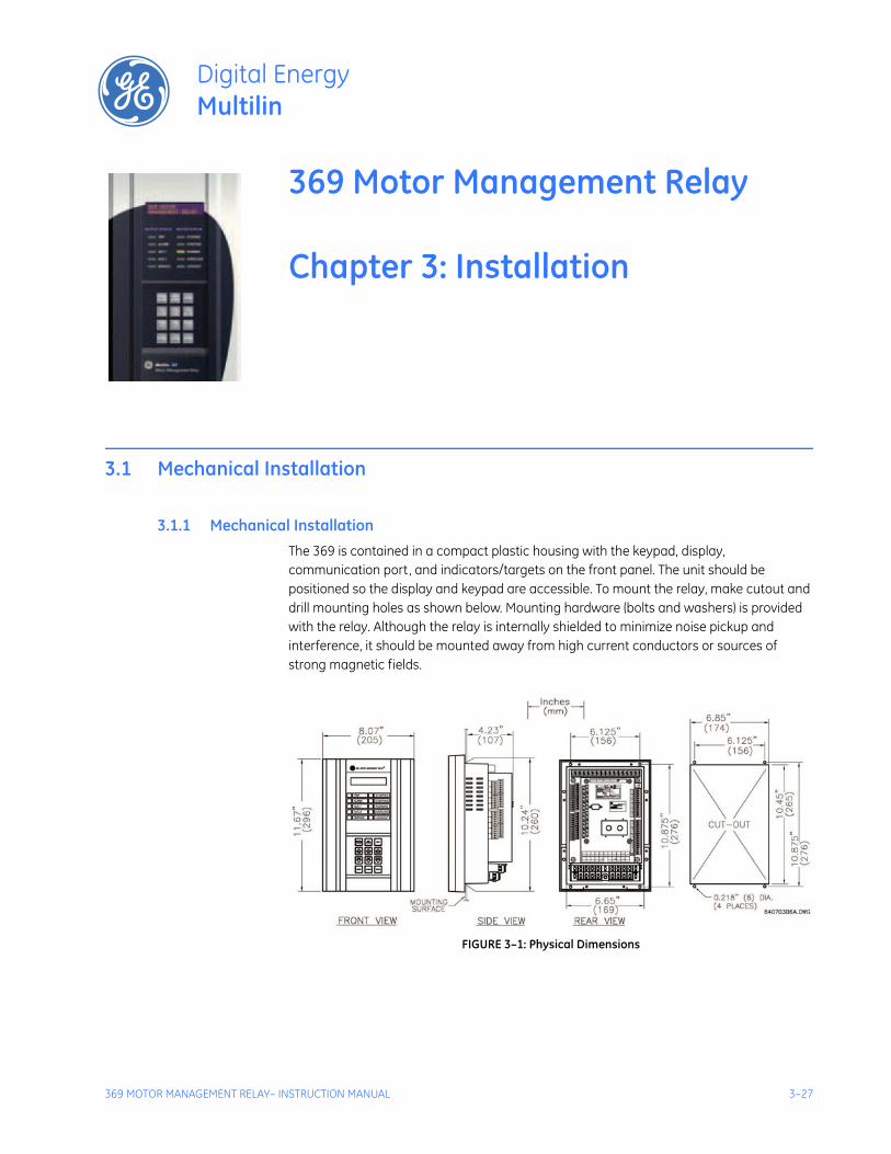
369 MOTOR MANAGEMENT RELAY– INSTRUCTION MANUAL 3–27
369 Motor Management Relay
Chapter 3: Installation
Digital EnergyMultilin
Installation
3.1 Mechanical Installation
3.1.1 Mechanical InstallationThe 369 is contained in a compact plastic housing with the keypad, display, communication port, and indicators/targets on the front panel. The unit should be positioned so the display and keypad are accessible. To mount the relay, make cutout and drill mounting holes as shown below. Mounting hardware (bolts and washers) is provided with the relay. Although the relay is internally shielded to minimize noise pickup and interference, it should be mounted away from high current conductors or sources of strong magnetic fields.
FIGURE 3–1: Physical Dimensions
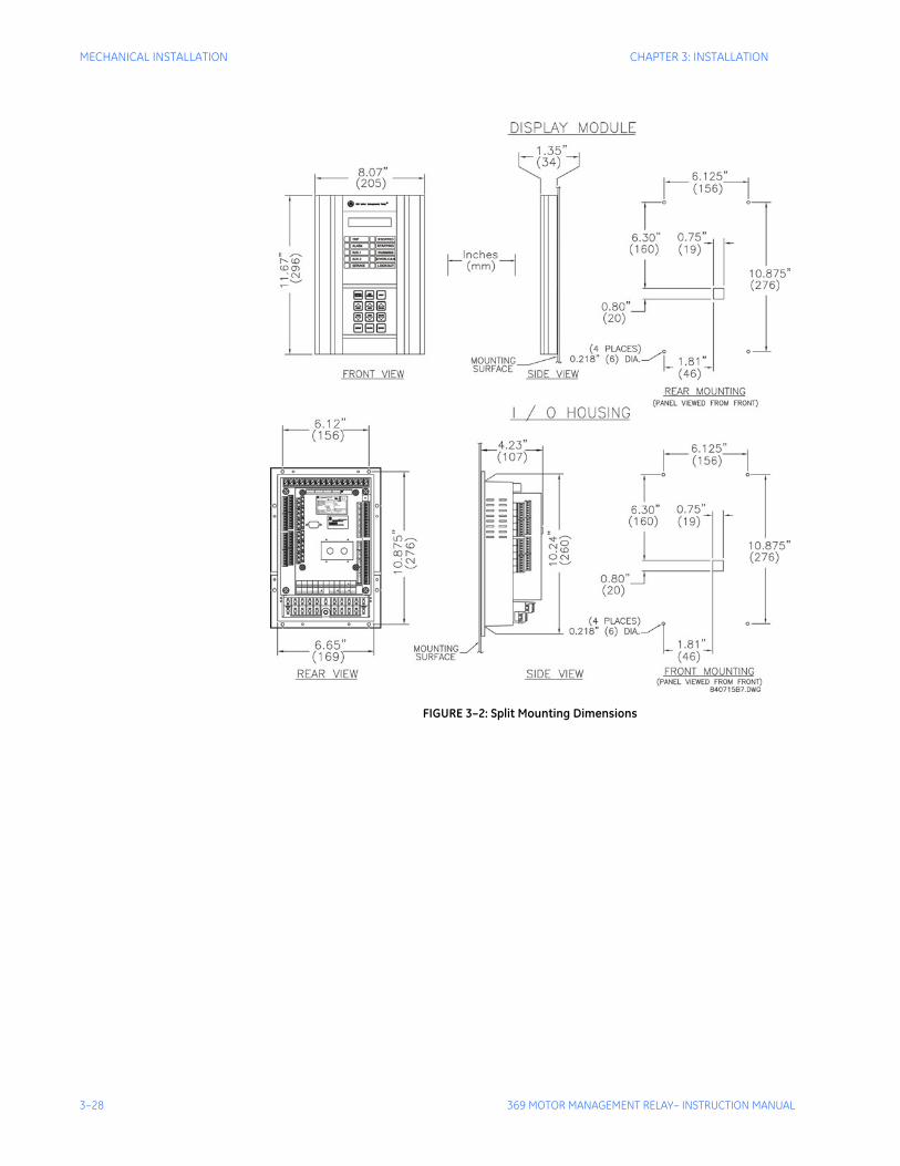
3–28 369 MOTOR MANAGEMENT RELAY– INSTRUCTION MANUAL
MECHANICAL INSTALLATION CHAPTER 3: INSTALLATION
FIGURE 3–2: Split Mounting Dimensions
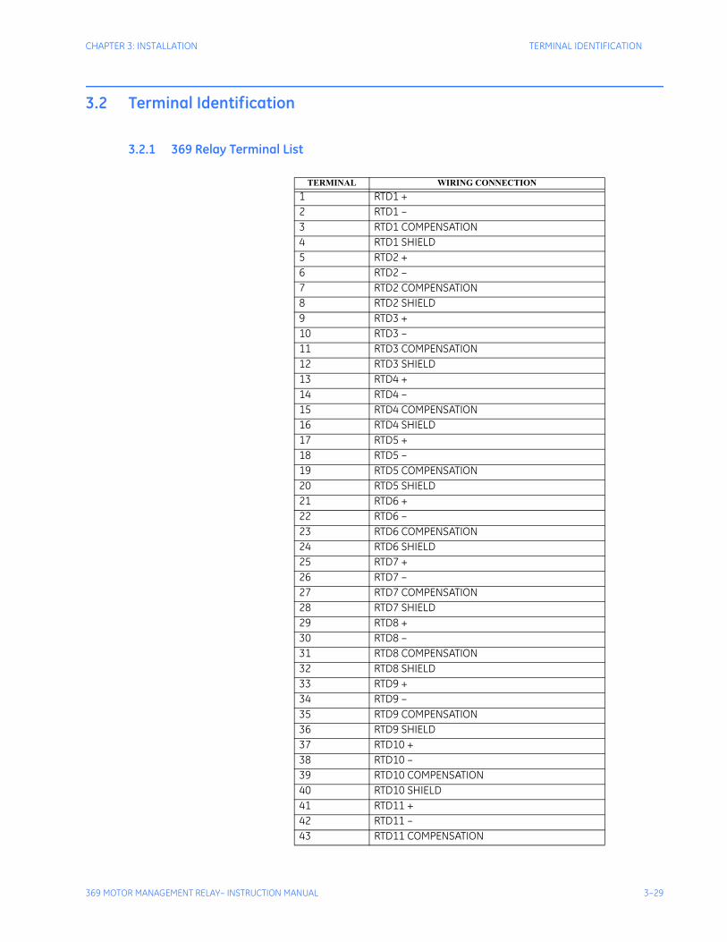
CHAPTER 3: INSTALLATION TERMINAL IDENTIFICATION
369 MOTOR MANAGEMENT RELAY– INSTRUCTION MANUAL 3–29
3.2 Terminal Identification
3.2.1 369 Relay Terminal List
TERMINAL WIRING CONNECTION1 RTD1 +2 RTD1 –3 RTD1 COMPENSATION4 RTD1 SHIELD5 RTD2 +6 RTD2 –7 RTD2 COMPENSATION8 RTD2 SHIELD9 RTD3 +10 RTD3 –11 RTD3 COMPENSATION12 RTD3 SHIELD13 RTD4 +14 RTD4 –15 RTD4 COMPENSATION16 RTD4 SHIELD17 RTD5 +18 RTD5 –19 RTD5 COMPENSATION20 RTD5 SHIELD21 RTD6 +22 RTD6 –23 RTD6 COMPENSATION24 RTD6 SHIELD25 RTD7 +26 RTD7 –27 RTD7 COMPENSATION28 RTD7 SHIELD29 RTD8 +30 RTD8 –31 RTD8 COMPENSATION32 RTD8 SHIELD33 RTD9 +34 RTD9 –35 RTD9 COMPENSATION36 RTD9 SHIELD37 RTD10 +38 RTD10 –39 RTD10 COMPENSATION40 RTD10 SHIELD41 RTD11 +42 RTD11 –43 RTD11 COMPENSATION
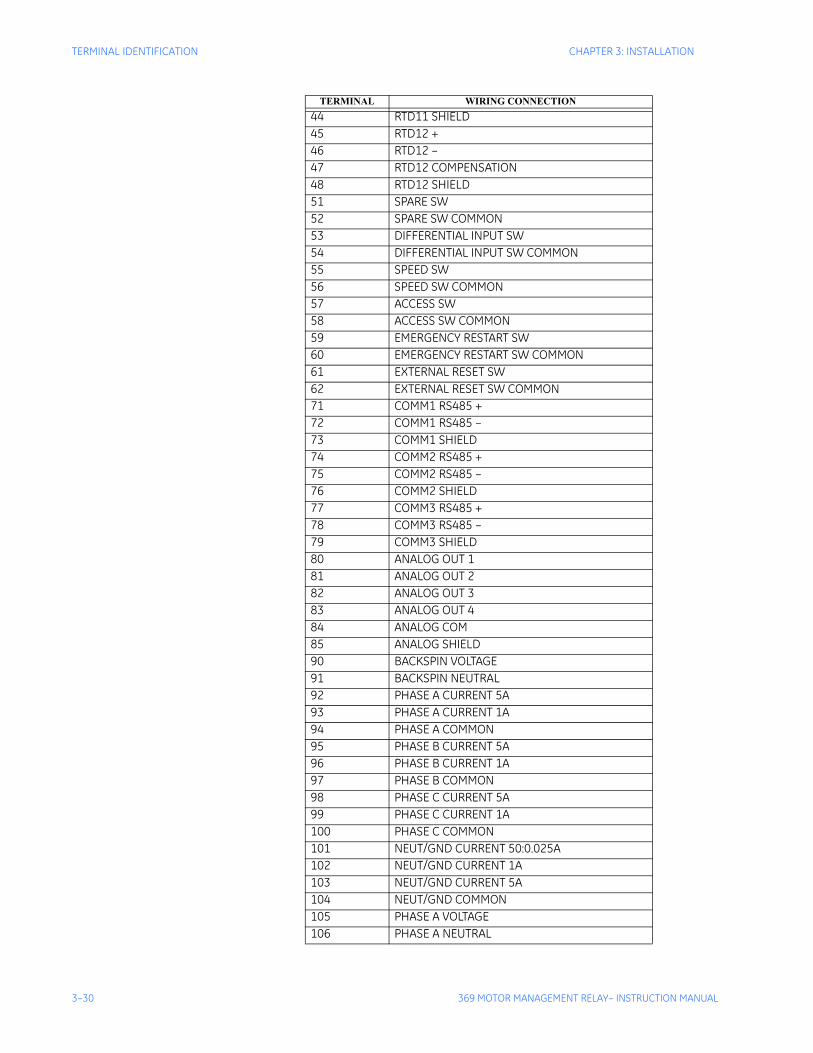
3–30 369 MOTOR MANAGEMENT RELAY– INSTRUCTION MANUAL
TERMINAL IDENTIFICATION CHAPTER 3: INSTALLATION
44 RTD11 SHIELD45 RTD12 +46 RTD12 –47 RTD12 COMPENSATION48 RTD12 SHIELD51 SPARE SW52 SPARE SW COMMON53 DIFFERENTIAL INPUT SW54 DIFFERENTIAL INPUT SW COMMON55 SPEED SW56 SPEED SW COMMON57 ACCESS SW58 ACCESS SW COMMON59 EMERGENCY RESTART SW60 EMERGENCY RESTART SW COMMON61 EXTERNAL RESET SW62 EXTERNAL RESET SW COMMON71 COMM1 RS485 +72 COMM1 RS485 –73 COMM1 SHIELD74 COMM2 RS485 +75 COMM2 RS485 –76 COMM2 SHIELD77 COMM3 RS485 +78 COMM3 RS485 –79 COMM3 SHIELD80 ANALOG OUT 181 ANALOG OUT 282 ANALOG OUT 383 ANALOG OUT 484 ANALOG COM85 ANALOG SHIELD90 BACKSPIN VOLTAGE91 BACKSPIN NEUTRAL92 PHASE A CURRENT 5A93 PHASE A CURRENT 1A94 PHASE A COMMON95 PHASE B CURRENT 5A96 PHASE B CURRENT 1A97 PHASE B COMMON98 PHASE C CURRENT 5A99 PHASE C CURRENT 1A100 PHASE C COMMON101 NEUT/GND CURRENT 50:0.025A102 NEUT/GND CURRENT 1A103 NEUT/GND CURRENT 5A104 NEUT/GND COMMON105 PHASE A VOLTAGE106 PHASE A NEUTRAL
TERMINAL WIRING CONNECTION
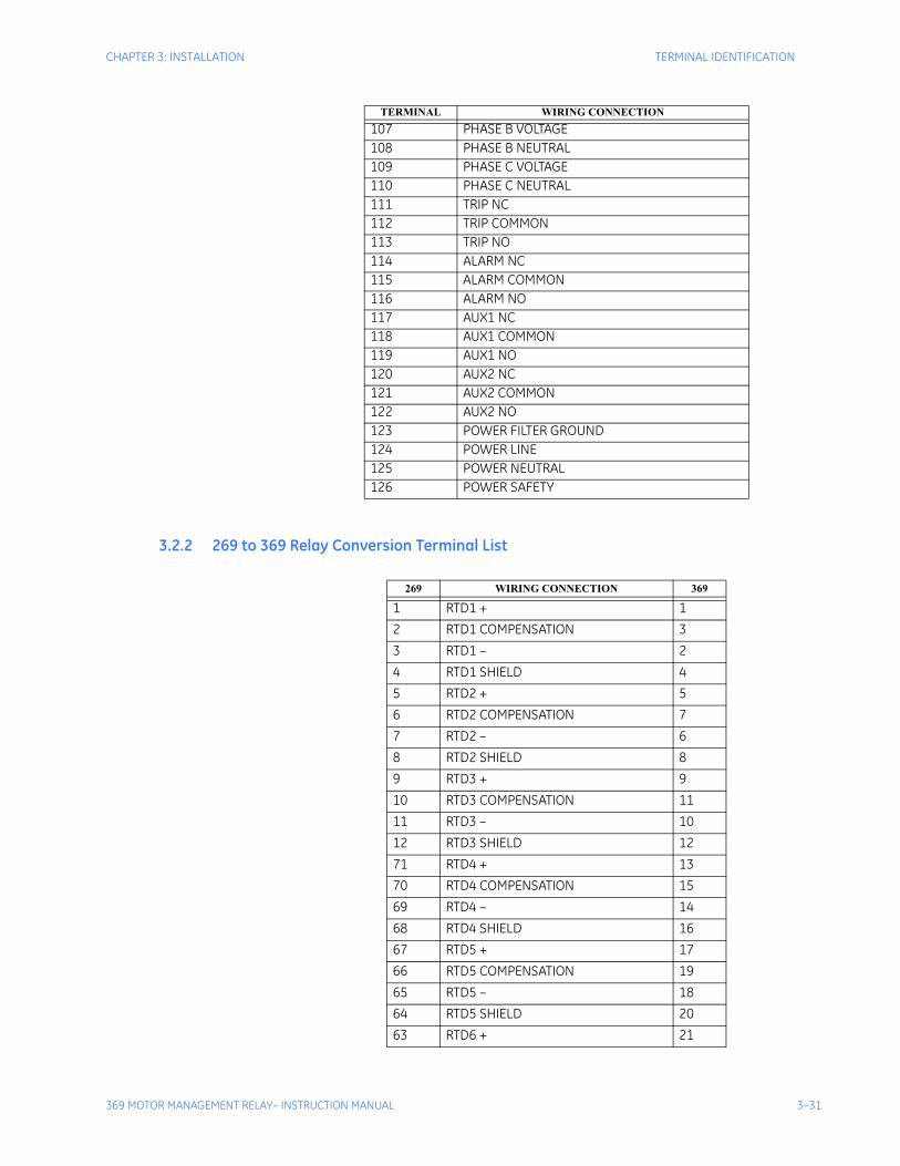
CHAPTER 3: INSTALLATION TERMINAL IDENTIFICATION
369 MOTOR MANAGEMENT RELAY– INSTRUCTION MANUAL 3–31
3.2.2 269 to 369 Relay Conversion Terminal List
107 PHASE B VOLTAGE108 PHASE B NEUTRAL109 PHASE C VOLTAGE110 PHASE C NEUTRAL111 TRIP NC112 TRIP COMMON113 TRIP NO114 ALARM NC115 ALARM COMMON116 ALARM NO117 AUX1 NC118 AUX1 COMMON119 AUX1 NO120 AUX2 NC121 AUX2 COMMON122 AUX2 NO123 POWER FILTER GROUND124 POWER LINE125 POWER NEUTRAL126 POWER SAFETY
TERMINAL WIRING CONNECTION
269 WIRING CONNECTION 369
1 RTD1 + 12 RTD1 COMPENSATION 33 RTD1 – 24 RTD1 SHIELD 45 RTD2 + 56 RTD2 COMPENSATION 77 RTD2 – 68 RTD2 SHIELD 89 RTD3 + 910 RTD3 COMPENSATION 1111 RTD3 – 1012 RTD3 SHIELD 1271 RTD4 + 1370 RTD4 COMPENSATION 1569 RTD4 – 1468 RTD4 SHIELD 1667 RTD5 + 1766 RTD5 COMPENSATION 1965 RTD5 – 1864 RTD5 SHIELD 2063 RTD6 + 21
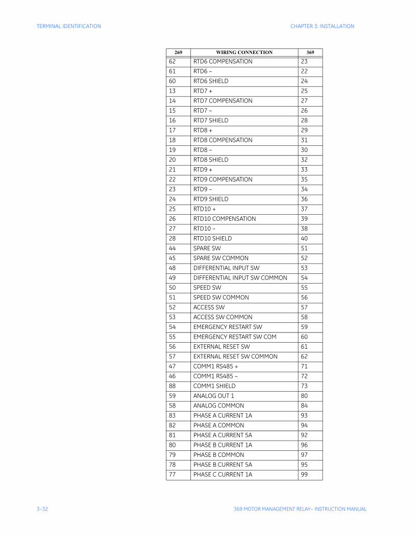
3–32 369 MOTOR MANAGEMENT RELAY– INSTRUCTION MANUAL
TERMINAL IDENTIFICATION CHAPTER 3: INSTALLATION
62 RTD6 COMPENSATION 2361 RTD6 – 2260 RTD6 SHIELD 2413 RTD7 + 2514 RTD7 COMPENSATION 2715 RTD7 – 2616 RTD7 SHIELD 2817 RTD8 + 2918 RTD8 COMPENSATION 3119 RTD8 – 3020 RTD8 SHIELD 3221 RTD9 + 3322 RTD9 COMPENSATION 3523 RTD9 – 3424 RTD9 SHIELD 3625 RTD10 + 3726 RTD10 COMPENSATION 3927 RTD10 – 3828 RTD10 SHIELD 4044 SPARE SW 5145 SPARE SW COMMON 5248 DIFFERENTIAL INPUT SW 5349 DIFFERENTIAL INPUT SW COMMON 5450 SPEED SW 5551 SPEED SW COMMON 5652 ACCESS SW 5753 ACCESS SW COMMON 5854 EMERGENCY RESTART SW 5955 EMERGENCY RESTART SW COM 6056 EXTERNAL RESET SW 6157 EXTERNAL RESET SW COMMON 6247 COMM1 RS485 + 7146 COMM1 RS485 – 7288 COMM1 SHIELD 7359 ANALOG OUT 1 8058 ANALOG COMMON 8483 PHASE A CURRENT 1A 9382 PHASE A COMMON 9481 PHASE A CURRENT 5A 9280 PHASE B CURRENT 1A 9679 PHASE B COMMON 9778 PHASE B CURRENT 5A 9577 PHASE C CURRENT 1A 99
269 WIRING CONNECTION 369
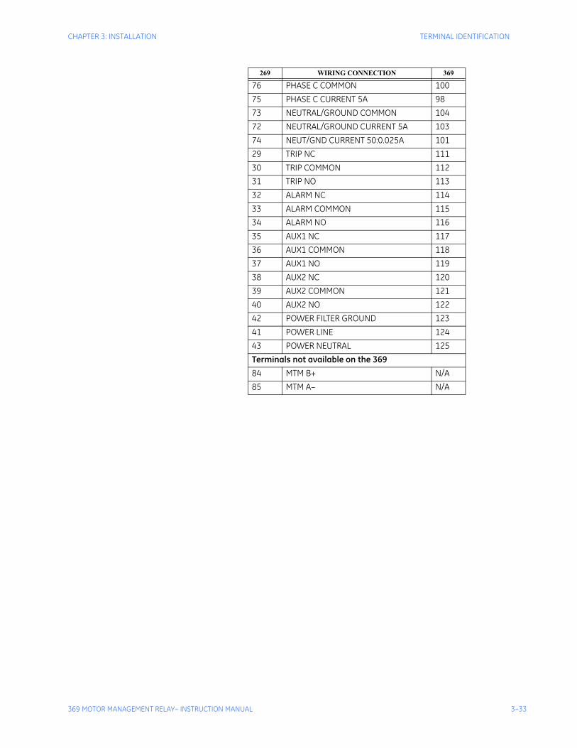
CHAPTER 3: INSTALLATION TERMINAL IDENTIFICATION
369 MOTOR MANAGEMENT RELAY– INSTRUCTION MANUAL 3–33
76 PHASE C COMMON 10075 PHASE C CURRENT 5A 9873 NEUTRAL/GROUND COMMON 10472 NEUTRAL/GROUND CURRENT 5A 10374 NEUT/GND CURRENT 50:0.025A 10129 TRIP NC 11130 TRIP COMMON 11231 TRIP NO 11332 ALARM NC 11433 ALARM COMMON 11534 ALARM NO 11635 AUX1 NC 11736 AUX1 COMMON 11837 AUX1 NO 11938 AUX2 NC 12039 AUX2 COMMON 12140 AUX2 NO 12242 POWER FILTER GROUND 12341 POWER LINE 12443 POWER NEUTRAL 125Terminals not available on the 36984 MTM B+ N/A85 MTM A– N/A
269 WIRING CONNECTION 369
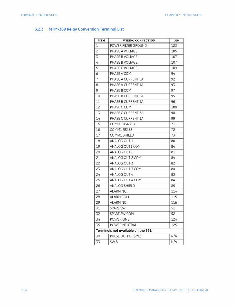
3–34 369 MOTOR MANAGEMENT RELAY– INSTRUCTION MANUAL
TERMINAL IDENTIFICATION CHAPTER 3: INSTALLATION
3.2.3 MTM-369 Relay Conversion Terminal List
MTM WIRING CONNECTION 369
1 POWER FILTER GROUND 1232 PHASE A VOLTAGE 1053 PHASE B VOLTAGE 1074 PHASE B VOLTAGE 1075 PHASE C VOLTAGE 1096 PHASE A COM 947 PHASE A CURRENT 5A 928 PHASE A CURRENT 1A 939 PHASE B COM 9710 PHASE B CURRENT 5A 9511 PHASE B CURRENT 1A 9612 PHASE C COM 10013 PHASE C CURRENT 5A 9814 PHASE C CURRENT 1A 9915 COMM1 RS485 + 7116 COMM1 RS485 – 7217 COMM1 SHIELD 7318 ANALOG OUT 1 8019 ANALOG OUT1 COM 8420 ANALOG OUT 2 8121 ANALOG OUT 2 COM 8422 ANALOG OUT 3 8223 ANALOG OUT 3 COM 8424 ANALOG OUT 4 8325 ANALOG OUT 4 COM 8426 ANALOG SHIELD 8527 ALARM NC 11428 ALARM COM 11529 ALARM NO 11631 SPARE SW 5132 SPARE SW COM 5234 POWER LINE 12435 POWER NEUTRAL 125Terminals not available on the 369:30 PULSE OUTPUT (P/O) N/A33 SW.B N/A
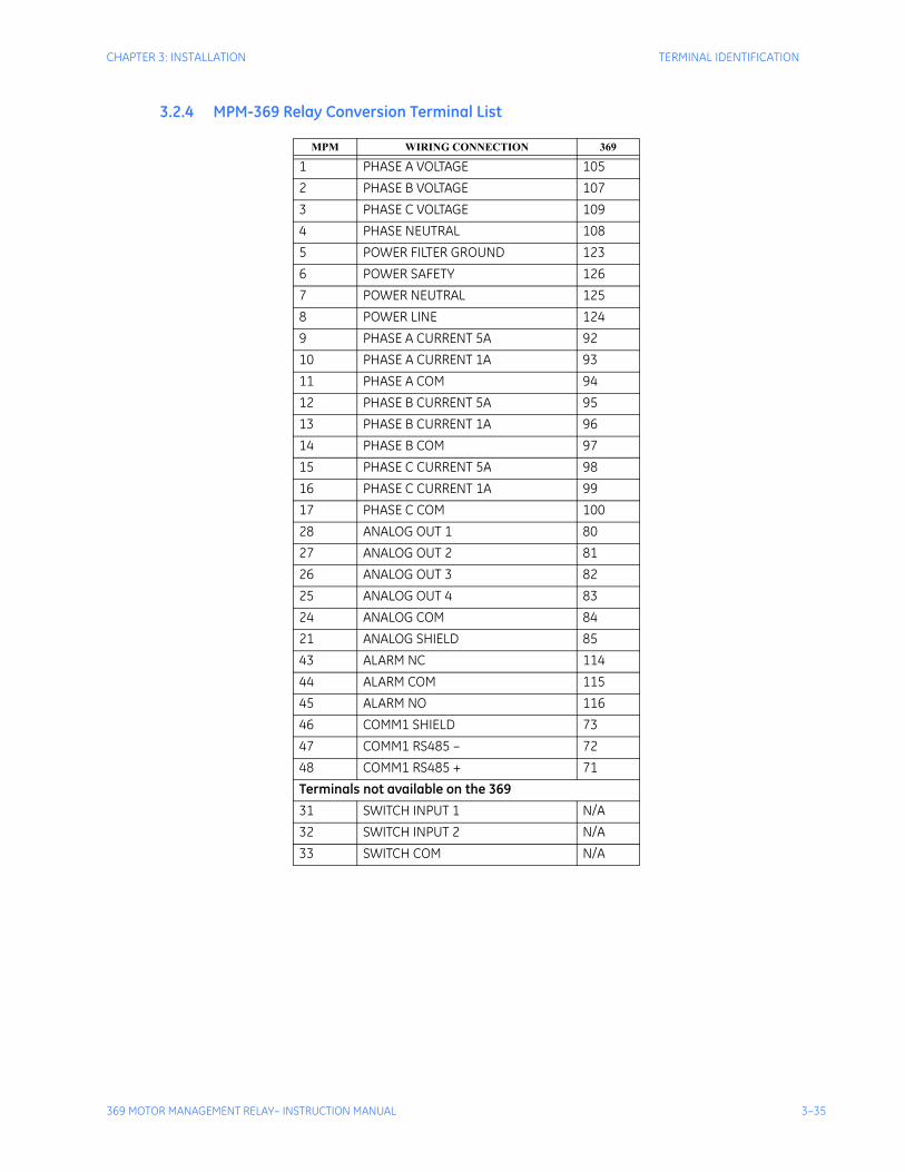
CHAPTER 3: INSTALLATION TERMINAL IDENTIFICATION
369 MOTOR MANAGEMENT RELAY– INSTRUCTION MANUAL 3–35
3.2.4 MPM-369 Relay Conversion Terminal List
MPM WIRING CONNECTION 369
1 PHASE A VOLTAGE 1052 PHASE B VOLTAGE 1073 PHASE C VOLTAGE 1094 PHASE NEUTRAL 1085 POWER FILTER GROUND 1236 POWER SAFETY 1267 POWER NEUTRAL 1258 POWER LINE 1249 PHASE A CURRENT 5A 9210 PHASE A CURRENT 1A 9311 PHASE A COM 9412 PHASE B CURRENT 5A 9513 PHASE B CURRENT 1A 9614 PHASE B COM 9715 PHASE C CURRENT 5A 9816 PHASE C CURRENT 1A 9917 PHASE C COM 10028 ANALOG OUT 1 8027 ANALOG OUT 2 8126 ANALOG OUT 3 8225 ANALOG OUT 4 8324 ANALOG COM 8421 ANALOG SHIELD 8543 ALARM NC 11444 ALARM COM 11545 ALARM NO 11646 COMM1 SHIELD 7347 COMM1 RS485 – 7248 COMM1 RS485 + 71Terminals not available on the 36931 SWITCH INPUT 1 N/A32 SWITCH INPUT 2 N/A33 SWITCH COM N/A
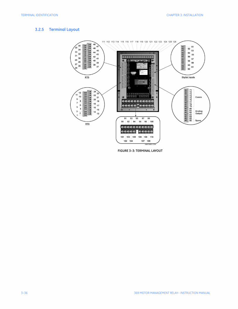
3–36 369 MOTOR MANAGEMENT RELAY– INSTRUCTION MANUAL
TERMINAL IDENTIFICATION CHAPTER 3: INSTALLATION
3.2.5 Terminal Layout
FIGURE 3–3: TERMINAL LAYOUT
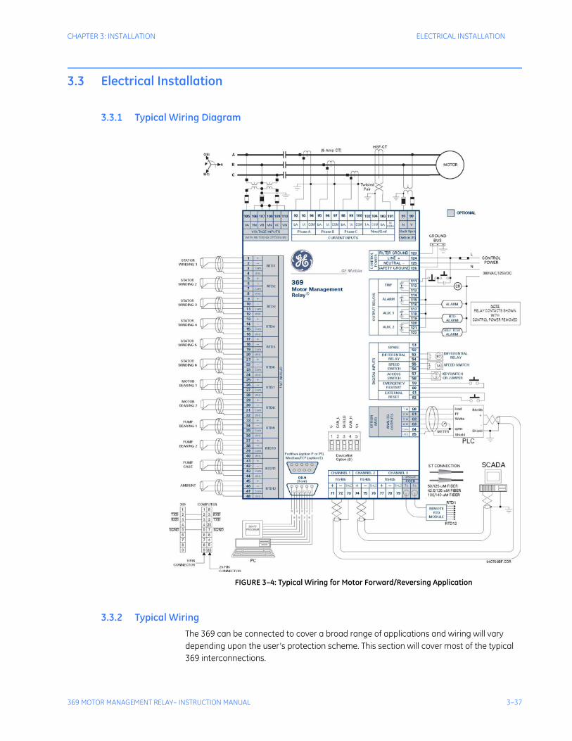
CHAPTER 3: INSTALLATION ELECTRICAL INSTALLATION
369 MOTOR MANAGEMENT RELAY– INSTRUCTION MANUAL 3–37
3.3 Electrical Installation
3.3.1 Typical Wiring Diagram
FIGURE 3–4: Typical Wiring for Motor Forward/Reversing Application
3.3.2 Typical Wiring The 369 can be connected to cover a broad range of applications and wiring will vary depending upon the user’s protection scheme. This section will cover most of the typical 369 interconnections.
3–38 369 MOTOR MANAGEMENT RELAY– INSTRUCTION MANUAL
ELECTRICAL INSTALLATION CHAPTER 3: INSTALLATION
In this section, the terminals have been logically grouped together for explanatory purposes. A typical wiring diagram for the 369 is shown above in FIGURE 3–4: Typical Wiring for Motor Forward/Reversing Application on page 3–37 and the terminal arrangement has been detailed in FIGURE 3–3: TERMINAL LAYOUT on page 3–36. For further information on applications not covered here, refer to Chapter : Applications or contact the factory for further information.
Hazard may result if the product is not used for intended purposes. This equipment can only be serviced by trained personnel.
Do not run signal wires in the same conduit or bundle that carries power mains or high level voltage or currents.
3.3.3 Control Power
VERIFY THAT THE CONTROL POWER SUPPLIED TO THE RELAY IS WITHIN THE RANGE COVERED BY THE ORDERED 369 RELAY’S CONTROL POWER.
The 369 has a built-in switchmode supply. It can operate with either AC or DC voltage applied to it . The relay reboot time of the 369 is 2 seconds after the control power is applied. For applications where the control power for the 369 is available from the same AC source as that of the motor, it is recommended an uninterrupted power supply be used to power up the relay or, alternatively, use a separate DC source to power up.
Extensive filtering and transient protection has been incorporated into the 369 to ensure reliable operation in harsh industrial environments. Transient energy is removed from the relay and conducted to ground via the ground terminal. This terminal must be connected to the cubicle ground bus using a 10 AWG wire or a ground braid. Do not daisy-chain grounds with other relays or devices. Each should have its own connection to the ground bus.
The internal supply is protected via a 3.15 A slo-blo fuse that is accessible for replacement. If it must be replaced ensure that it is replaced with a fuse of equal size (see FUSE on page 2–13).
3.3.4 Phase Current (CT) InputsThe 369 requires one CT for each of the three motor phase currents to be input into the relay. There are no internal ground connections for the CT inputs. Refer to Chapter : Applications for information on two CT connections.
Table 3–1: 369 POWER SUPPLY RANGES
369 POWER SUPPLY AC RANGE DC RANGE
HI 60 to 265 V 50 to 300 V
LO 20 to 48 V 20 to 60 V
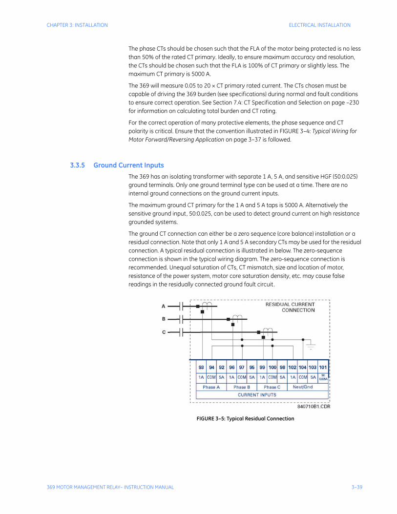
CHAPTER 3: INSTALLATION ELECTRICAL INSTALLATION
369 MOTOR MANAGEMENT RELAY– INSTRUCTION MANUAL 3–39
The phase CTs should be chosen such that the FLA of the motor being protected is no less than 50% of the rated CT primary. Ideally, to ensure maximum accuracy and resolution, the CTs should be chosen such that the FLA is 100% of CT primary or slightly less. The maximum CT primary is 5000 A.
The 369 will measure 0.05 to 20 × CT primary rated current. The CTs chosen must be capable of driving the 369 burden (see specifications) during normal and fault conditions to ensure correct operation. See Section 7.4: CT Specification and Selection on page –230 for information on calculating total burden and CT rating.
For the correct operation of many protective elements, the phase sequence and CT polarity is critical. Ensure that the convention illustrated in FIGURE 3–4: Typical Wiring for Motor Forward/Reversing Application on page 3–37 is followed.
3.3.5 Ground Current InputsThe 369 has an isolating transformer with separate 1 A, 5 A, and sensitive HGF (50:0.025) ground terminals. Only one ground terminal type can be used at a time. There are no internal ground connections on the ground current inputs.
The maximum ground CT primary for the 1 A and 5 A taps is 5000 A. Alternatively the sensitive ground input, 50:0.025, can be used to detect ground current on high resistance grounded systems.
The ground CT connection can either be a zero sequence (core balance) installation or a residual connection. Note that only 1 A and 5 A secondary CTs may be used for the residual connection. A typical residual connection is illustrated in below. The zero-sequence connection is shown in the typical wiring diagram. The zero-sequence connection is recommended. Unequal saturation of CTs, CT mismatch, size and location of motor, resistance of the power system, motor core saturation density, etc. may cause false readings in the residually connected ground fault circuit.
FIGURE 3–5: Typical Residual Connection
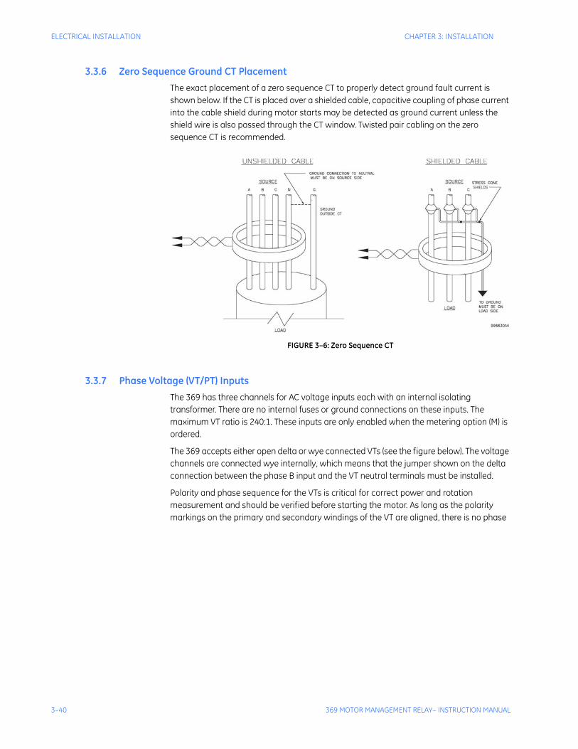
3–40 369 MOTOR MANAGEMENT RELAY– INSTRUCTION MANUAL
ELECTRICAL INSTALLATION CHAPTER 3: INSTALLATION
3.3.6 Zero Sequence Ground CT PlacementThe exact placement of a zero sequence CT to properly detect ground fault current is shown below. If the CT is placed over a shielded cable, capacitive coupling of phase current into the cable shield during motor starts may be detected as ground current unless the shield wire is also passed through the CT window. Twisted pair cabling on the zero sequence CT is recommended.
FIGURE 3–6: Zero Sequence CT
3.3.7 Phase Voltage (VT/PT) InputsThe 369 has three channels for AC voltage inputs each with an internal isolating transformer. There are no internal fuses or ground connections on these inputs. The maximum VT ratio is 240:1. These inputs are only enabled when the metering option (M) is ordered.
The 369 accepts either open delta or wye connected VTs (see the figure below). The voltage channels are connected wye internally, which means that the jumper shown on the delta connection between the phase B input and the VT neutral terminals must be installed.
Polarity and phase sequence for the VTs is critical for correct power and rotation measurement and should be verified before starting the motor. As long as the polarity markings on the primary and secondary windings of the VT are aligned, there is no phase
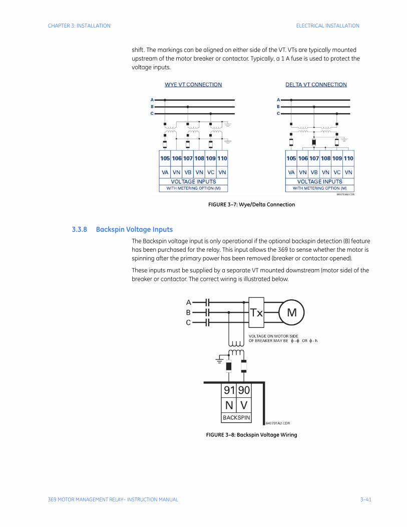
CHAPTER 3: INSTALLATION ELECTRICAL INSTALLATION
369 MOTOR MANAGEMENT RELAY– INSTRUCTION MANUAL 3–41
shift. The markings can be aligned on either side of the VT. VTs are typically mounted upstream of the motor breaker or contactor. Typically, a 1 A fuse is used to protect the voltage inputs.
FIGURE 3–7: Wye/Delta Connection
3.3.8 Backspin Voltage InputsThe Backspin voltage input is only operational if the optional backspin detection (B) feature has been purchased for the relay. This input allows the 369 to sense whether the motor is spinning after the primary power has been removed (breaker or contactor opened).
These inputs must be supplied by a separate VT mounted downstream (motor side) of the breaker or contactor. The correct wiring is illustrated below.
FIGURE 3–8: Backspin Voltage Wiring
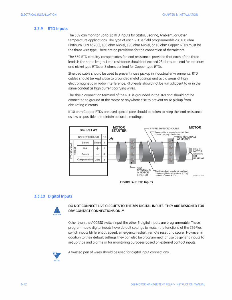
3–42 369 MOTOR MANAGEMENT RELAY– INSTRUCTION MANUAL
ELECTRICAL INSTALLATION CHAPTER 3: INSTALLATION
3.3.9 RTD InputsThe 369 can monitor up to 12 RTD inputs for Stator, Bearing, Ambient, or Other temperature applications. The type of each RTD is field programmable as: 100 ohm Platinum (DIN 43760), 100 ohm Nickel, 120 ohm Nickel, or 10 ohm Copper. RTDs must be the three wire type. There are no provisions for the connection of thermistors.
The 369 RTD circuitry compensates for lead resistance, provided that each of the three leads is the same length. Lead resistance should not exceed 25 ohms per lead for platinum and nickel type RTDs or 3 ohms per lead for Copper type RTDs.
Shielded cable should be used to prevent noise pickup in industrial environments. RTD cables should be kept close to grounded metal casings and avoid areas of high electromagnetic or radio interference. RTD leads should not be run adjacent to or in the same conduit as high current carrying wires.
The shield connection terminal of the RTD is grounded in the 369 and should not be connected to ground at the motor or anywhere else to prevent noise pickup from circulating currents.
If 10 ohm Copper RTDs are used special care should be taken to keep the lead resistance as low as possible to maintain accurate readings.
FIGURE 3–9: RTD Inputs
3.3.10 Digital Inputs
DO NOT CONNECT LIVE CIRCUITS TO THE 369 DIGITAL INPUTS. THEY ARE DESIGNED FOR DRY CONTACT CONNECTIONS ONLY.
Other than the ACCESS switch input the other 5 digital inputs are programmable. These programmable digital inputs have default settings to match the functions of the 269Plus switch inputs (differential, speed, emergency restart, remote reset and spare). However in addition to their default settings they can also be programmed for use as generic inputs to set up trips and alarms or for monitoring purposes based on external contact inputs.
Note A twisted pair of wires should be used for digital input connections.
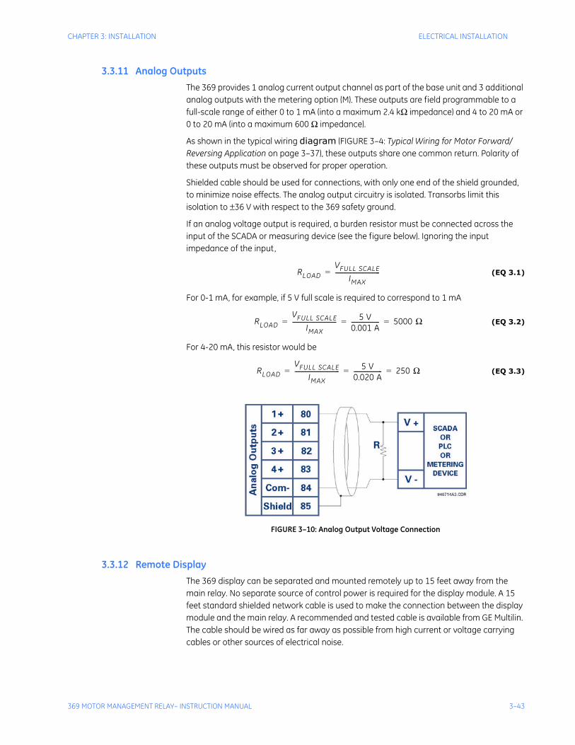
CHAPTER 3: INSTALLATION ELECTRICAL INSTALLATION
369 MOTOR MANAGEMENT RELAY– INSTRUCTION MANUAL 3–43
3.3.11 Analog OutputsThe 369 provides 1 analog current output channel as part of the base unit and 3 additional analog outputs with the metering option (M). These outputs are field programmable to a full-scale range of either 0 to 1 mA (into a maximum 2.4 kΩ impedance) and 4 to 20 mA or 0 to 20 mA (into a maximum 600 Ω impedance).
As shown in the typical wiring diagram (FIGURE 3–4: Typical Wiring for Motor Forward/Reversing Application on page 3–37), these outputs share one common return. Polarity of these outputs must be observed for proper operation.
Shielded cable should be used for connections, with only one end of the shield grounded, to minimize noise effects. The analog output circuitry is isolated. Transorbs limit this isolation to ±36 V with respect to the 369 safety ground.
If an analog voltage output is required, a burden resistor must be connected across the input of the SCADA or measuring device (see the figure below). Ignoring the input impedance of the input,
(EQ 3.1)
For 0-1 mA, for example, if 5 V full scale is required to correspond to 1 mA
(EQ 3.2)
For 4-20 mA, this resistor would be
(EQ 3.3)
FIGURE 3–10: Analog Output Voltage Connection
3.3.12 Remote DisplayThe 369 display can be separated and mounted remotely up to 15 feet away from the main relay. No separate source of control power is required for the display module. A 15 feet standard shielded network cable is used to make the connection between the display module and the main relay. A recommended and tested cable is available from GE Multilin. The cable should be wired as far away as possible from high current or voltage carrying cables or other sources of electrical noise.
RLOADVFULL SCALE
IMAX------------------------------=
RLOADVFULL SCALE
IMAX------------------------------ 5 V
0.001 A------------------- 5000 Ω= = =
RLOADVFULL SCALE
IMAX------------------------------ 5 V
0.020 A------------------- 250 Ω= = =

3–44 369 MOTOR MANAGEMENT RELAY– INSTRUCTION MANUAL
ELECTRICAL INSTALLATION CHAPTER 3: INSTALLATION
In addition the display module must be grounded if mounted remotely. A ground screw is provided on the back of the display module to facilitate this. A 12 AWG wire is recommended and should be connected to the same ground bus as the main relay unit.
The 369 relay will still function and protect the motor without the display connected.
3.3.13 Output RelaysThe 369 provides four (4) form C output relays. They are labeled Trip, Aux 1, Aux 2, and Alarm. Each relay has normally open (NO) and normally closed (NC) contacts and can switch up to 8 A at either 250 V AC or 30 V DC with a resistive load. The NO or NC state is determined by the ‘no power’ state of the relay outputs.
All four output relays may be programmed for fail-safe or non-fail-safe operation. When in fail-safe mode, output relay activation or a loss of control power will cause the contacts to go to their power down state.
Example:
• A fail-safe NO contact closes when the 369 is powered up (if no prior unreset trip conditions) and will open when activated (tripped) or when the 369 loses control power.
• A non-fail-safe NO contact remains open when the 369 is powered up (unless a prior unreset trip condition) and will close only when activated (tripped). If control power is lost while the output relay is activated (NO contacts closed) the NO contacts will open.
Thus, in order to cause a trip on loss of control power to the 369, the Trip relay should be programmed as fail-safe. See the figure below for typical wiring of contactors and breakers for fail-safe and non-fail-safe operation. Output relays remain latched after activation if the fault condition persists or the protection element has been programmed as latched. This means that once this relay has been activated it remains in the active state until the 369 is manually reset.
The Trip relay cannot be reset if a timed lockout is in effect. Lockout time will be adhered to regardless of whether control power is present or not. The relay contacts may be reset if motor conditions allow, by pressing the RESET key, using the REMOTE RESET switch or via communications. The Emergency Restart feature overrides all features to reset the 369.
The rear of the 369 relay shows output relay contacts in their power down state.
Note In locations where system voltage disturbances cause voltage levels to dip below the control power range listed in specifications, any relay contact programmed as fail-safe may change state. Therefore, in any application where the ‘process’ is more critical
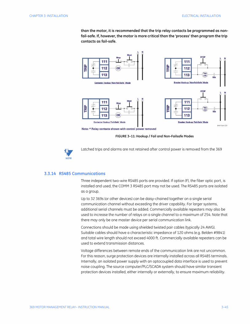
CHAPTER 3: INSTALLATION ELECTRICAL INSTALLATION
369 MOTOR MANAGEMENT RELAY– INSTRUCTION MANUAL 3–45
than the motor, it is recommended that the trip relay contacts be programmed as non-fail-safe. If, however, the motor is more critical than the ‘process’ then program the trip contacts as fail-safe.
FIGURE 3–11: Hookup / Fail and Non-Failsafe Modes
Note Latched trips and alarms are not retained after control power is removed from the 369
3.3.14 RS485 CommunicationsThree independent two-wire RS485 ports are provided. If option (F), the fiber optic port, is installed and used, the COMM 3 RS485 port may not be used. The RS485 ports are isolated as a group.
Up to 32 369s (or other devices) can be daisy-chained together on a single serial communication channel without exceeding the driver capability. For larger systems, additional serial channels must be added. Commercially available repeaters may also be used to increase the number of relays on a single channel to a maximum of 254. Note that there may only be one master device per serial communication link.
Connections should be made using shielded twisted pair cables (typically 24 AWG). Suitable cables should have a characteristic impedance of 120 ohms (e.g. Belden #9841) and total wire length should not exceed 4000 ft. Commercially available repeaters can be used to extend transmission distances.
Voltage differences between remote ends of the communication link are not uncommon. For this reason, surge protection devices are internally installed across all RS485 terminals. Internally, an isolated power supply with an optocoupled data interface is used to prevent noise coupling. The source computer/PLC/SCADA system should have similar transient protection devices installed, either internally or externally, to ensure maximum reliability.
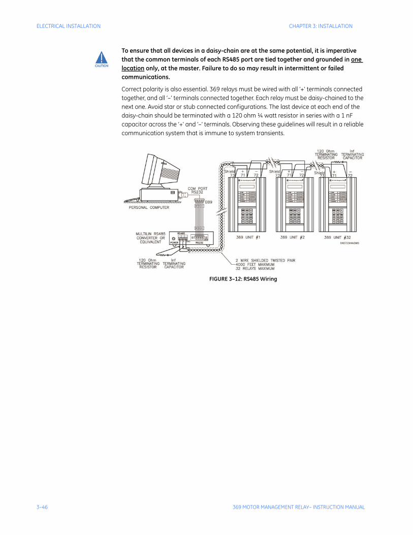
3–46 369 MOTOR MANAGEMENT RELAY– INSTRUCTION MANUAL
ELECTRICAL INSTALLATION CHAPTER 3: INSTALLATION
To ensure that all devices in a daisy-chain are at the same potential, it is imperative that the common terminals of each RS485 port are tied together and grounded in one location only, at the master. Failure to do so may result in intermittent or failed communications.
Correct polarity is also essential. 369 relays must be wired with all ‘+’ terminals connected together, and all ‘–’ terminals connected together. Each relay must be daisy-chained to the next one. Avoid star or stub connected configurations. The last device at each end of the daisy-chain should be terminated with a 120 ohm ¼ watt resistor in series with a 1 nF capacitor across the ‘+’ and ‘–’ terminals. Observing these guidelines will result in a reliable communication system that is immune to system transients.
FIGURE 3–12: RS485 Wiring
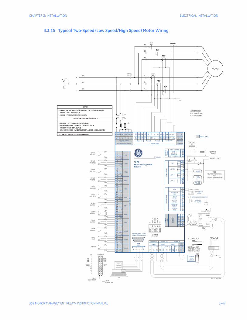
CHAPTER 3: INSTALLATION ELECTRICAL INSTALLATION
369 MOTOR MANAGEMENT RELAY– INSTRUCTION MANUAL 3–47
3.3.15 Typical Two-Speed (Low Speed/High Speed) Motor Wiring
369Motor Management
Relay
GROUND
BUS
840837A1.CDR
DB-9
(front)
STATOR
WINDING 1
METER
load
PLC
SCADA
RS485
PF +Watts
cpm-
Shield
Shield
-
STATOR
WINDING 2
STATOR
WINDING 3
STATOR
WINDING 4
STATOR
WINDING 5
STATOR
WINDING 6
MOTOR
BEARING 1
MOTOR
BEARING 2
PUMP
BEARING 1
PUMP
BEARING 2
PUMP
CASE
AMBIENT
369
TXD
TXDRXD
RXD
SGND SGND
COMPUTER
25 PIN
CONNECTOR
9 PIN
CONNECTOR
CONTROL
POWER
380VAC/125VDC
NOTE
RELAY CONTACTS SHOWN
WITH
CONTROL POWER REMOVED
RTD1
ST CONNECTION
50/125 uM FIBER
62.5/125 uM FIBER
100/140 uM FIBER
PC
RTD12
L
N
VA VN VB VN VC VN
VOLTAGE INPUTS
105 108106 109107 110
CURRENT INPUTSWITH METERING OPTION (M)
Neut/Gnd Back Spin
Option (B)
COM50:
0.025A5A VN1A
102 104 103 101
OPTIONAL
9091
CHANNEL 1
OPTIO
N(R
)
CHANNEL 2 CHANNEL 3
REMOTE
RTD
MODULE
RS485 RS485 RS485FIBER
71 74 7773 76 7972 75 78
82
81
83
4
12
16
20
24
28
32
36
40
44
48
8
3
11
15
19
23
27
31
35
39
43
47
7
2
10
14
18
22
26
30
34
38
42
46
6
1
9
13
17
21
25
29
33
37
41
45
5
Com
Com
Com
Com
Com
Com
Com
Com
Com
Com
Com
Com
shld.
shld.shld.
shld.
shld.
shld.
shld.
shld.
shld.
shld.
shld.
shld.
5
9
4 3 2 1
8 7 6
shld.
SHLD SHLD SHLD Tx Rx
1
3
4
AN
ALO
G
OU
TPU
TS
OPTI
ON
(M,B
)
RTD1
RTD3
RTD4
RTD5
RTD6
RTD7
RTD8
RTD9
RTD10
RTD11
RTD12
RTD2
SPARE
DIFFERENTIAL
RELAY
RTD
ALARM
SELF TEST
ALARM
ALARM
KEYSWITCH
OR JUMPER
SPEED 2 MONITOR SWITCH
DIFFERENTIAL
RELAY
SPEED
SWITCH
ACCESS
SWITCH
EMERGENCY
RESTART
EXTERNAL
RESET
DIG
ITA
LIN
PU
TS
51
59
61
52
60
62
53
54
55
56
57
58
111
126
125
124
123
112
113
114
115
116
117
118
119
120
121
122
OU
TPU
TRELA
YS
TRIP
ALARM
AUX. 1
AUX. 2
FILTER GROUND
LINE +
NEUTRAL -
SAFETY GROUNDCO
NTR
OL
PO
WER
CR
369 PC
PROGRAM
87
OPTION (F)
11 8
22 3
66 6
44 20
88 5
33 2
77 4
55 7
99 22
R
Profibus (option P or P1)
Modbus/TCP (option E)
GE Multilin
5A 5A1A
Phase A Phase CPhase B
COM 1A COM 5A COM1A
92 93 94 95 96 97 98 99 100
85
84Com-
shld.
80
2
V-
CA
N_L
SH
IELD
CA
N_H
V+
DeviceNet
Option (D)
MOTOR
GROUND CTGROUND CT
C
B
L2
L1
A
L3
BREAKER
CIRCUIT
A
B
C
L
L
L
H
H
H
ØA CT
100:5
ØB CTØB CT
100:5
ØC CTØC CT
100:5
ØA CT
50:5
ØB CTØB CT
50:5
ØC CTØC CT
50:5
MOTOR
STARTER STATUS
H
CONTACTORS:
H = High Speed
L = Low Speed
NOTES
- SPEED SWITCH INPUT DEDICATED AS TWO-SPEED MONITOR
SPEED 2 ADDITIONAL SETPOINTS.
- ENABLE 2 SPEED MOTOR PROTECTION
- SPEED 1 = L & SPEED 2 = H
- PROGRAM SPEED 2 PHASE CT PRIMARY & FLA
- SPEED 1 PROGRAMMED AS NORMAL
- SELECT SPEED 2 O/L CURVE
- PROGRAM SPEED 2 UNDERCURRENT AND/OR ACCELERATION
CT RATIOS SHOWN ARE JUST EXAMPLES

3–48 369 MOTOR MANAGEMENT RELAY– INSTRUCTION MANUAL
ELECTRICAL INSTALLATION CHAPTER 3: INSTALLATION
The following additional setpoints should be programmed:
ENABLE 2 SPEED MOTOR PROTECTION under 5.3.2: CT/VT Setup
Program SPEED2 PHASE CT PRIMARY, SPEED2 MOTOR FLA, and SPEED 2 SYSTEM PHASE SEQUENCE under 5.3.2: CT/VT Setup.
Select SPEED2 O/L CURVES under 5.13: S12 Two-speed Motor.
Program SPEED2 UNDERCURRENT and SPEED2 ACCELERATION under 5.13: S12 Two-speed Motor.
Note 1. Speed switch input dedicated as Two-speed monitor.
2. Speed 1 = L (Low) ; Speed 2 = H (High).
3. Speed 1 programmed as normal.
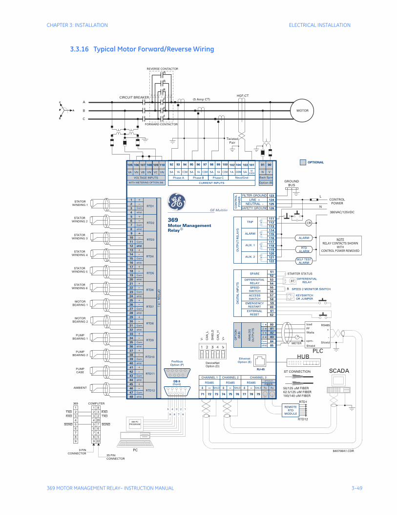
CHAPTER 3: INSTALLATION ELECTRICAL INSTALLATION
369 MOTOR MANAGEMENT RELAY– INSTRUCTION MANUAL 3–49
3.3.16 Typical Motor Forward/Reverse Wiring
369Motor ManagementRelay
GROUND
BUS
840708A1.CDR
DB-9(front)
STATOR
WINDING 1
METER
load
PLC
SCADA
RS485
PF +
Watts
cpm-
Shield
Shield
-
STATOR
WINDING 2
STATOR
WINDING 3
STATOR
WINDING 4
STATOR
WINDING 5
STATOR
WINDING 6
MOTOR
BEARING 1
MOTOR
BEARING 2
PUMP
BEARING 1
PUMP
BEARING 2
PUMP
CASE
AMBIENT
369
TXD
TXDRXD
RXD
SGND SGND
COMPUTER
25 PIN
CONNECTOR
9 PIN
CONNECTOR
(5 Amp CT)
Twisted
Pair
CONTROL
POWER
380VAC/125VDC
NOTE
RELAY CONTACTS SHOWN
WITH
CONTROL POWER REMOVED
RTD1
ST CONNECTION
50/125 uM FIBER
62.5/125 uM FIBER
100/140 uM FIBER
PC
RTD12
L
N
HGF-CT
MOTOR
VA VN VB VN VC VN
VOLTAGE INPUTS
105 108106 109107 110
CURRENT INPUTSWITH METERING OPTION (M)
Neut/Gnd Back Spin
Option (B)
COM50:
0.025A5A VN1A
102 104 103 101OPTIONAL
9091
CHANNEL 1
OP
TIO
N(
R)
CHANNEL 2 CHANNEL 3
REMOTE
RTD
MODULE
RS485 RS485 RS485FIBER
71 74 7773 76 7972 75 78
82
81
83
4
12
16
20
24
28
32
36
40
44
48
8
3
11
15
19
23
27
31
35
39
43
47
7
2
10
14
18
22
26
30
34
38
42
46
6
1
9
13
17
21
25
29
33
37
41
45
5
Com
Com
Com
Com
Com
Com
Com
Com
Com
Com
Com
Com
shld.
shld.shld.
shld.
shld.
shld.
shld.
shld.
shld.
shld.
shld.
shld.
5
9
4 3 2 1
8 7 6
shld.
SHLD SHLD SHLD Tx Rx
1
3
4
AN
AL
OG
OU
TP
UT
S
OP
TIO
N
(M,B
)
RTD1
RTD3
RTD4
RTD5
RTD6
RTD7
RTD8
RTD9
RTD10
RTD11
RTD12
RTD2
SPARE
DIFFERENTIAL
RELAY
RTD
ALARM
SELF TEST
ALARM
ALARM
KEYSWITCH
OR JUMPER
SPEED 2 MONITOR SWITCH
DIFFERENTIAL
RELAY
SPEED
SWITCH
ACCESS
SWITCH
EMERGENCY
RESTART
EXTERNAL
RESET
DIG
ITA
LIN
PU
TS
51
59
61
52
60
62
53
54
55
56
57
58
111
126
125
124
123
112
113
114
115
116
117
118
119
120
121
122
OU
TP
UT
RE
LA
YS
TRIP
ALARM
AUX. 1
AUX. 2
FILTER GROUND
LINE +
NEUTRAL -
SAFETY GROUNDCO
NT
RO
L
PO
WE
R
CR
369 PC
PROGRAM
87
OPTION (F)
11 8
22 3
66 6
44 20
88 5
33 2
77 4
55 7
99 22
R
Profibus
Option (P)
GE Multilin
5A 5A1A
Phase A Phase CPhase B
COM 1A COM 5A COM1A
92 93 94 95 96 97 98 99 100
85
84Com-
shld.
80
2
HUBEthernet
Option (E)
RJ-45
V-
CA
N_L
SH
IELD
CA
N_H
V+
DeviceNet
Option (D)
STARTER STATUS
R
R
R
F
F
F
REVERSE CONTACTOR
A
B
C
C
A
B
CIRCUIT BREAKER
R
FORWARD CONTACTOR
3–50 369 MOTOR MANAGEMENT RELAY– INSTRUCTION MANUAL
ELECTRICAL INSTALLATION CHAPTER 3: INSTALLATION
The following additional setpoints should be programmed:
Enable 2-SPEED MOTOR PROTECTION under 5.3.2: CT/VT Setup.
Program SPEED2 PHASE CT PRIMARY, SPEED2 MOTOR FLA, and SPEED2 SYSTEM PHASE SEQUENCE under 5.3.2: CT/VT Setup.
Select SPEED2 O/L CURVES under 5.13: S12 Two-speed Motor.
Program SPEED2 UNDERCURRENT and SPEED2 ACCELERATION under 5.13: S12 Two-speed Motor.
Note 1. VT must be connected on the breaker side of the contactor for proper power metering and phase reversal trip protection.
2. The system phase sequence of the VT input to the 369 must be the same as the system phase sequence setpoint and the phase sequence for forward rotation of the motor.
3. The phase sequence for the reverse direction must be set as the Speed 2 phase sequence.
4. Speed switch input dedicated as the Two-Speed monitor.
5. Speed 1 = F (Forward); Speed 2 = R (Reverse).
6. Speed 1 programmed as normal.
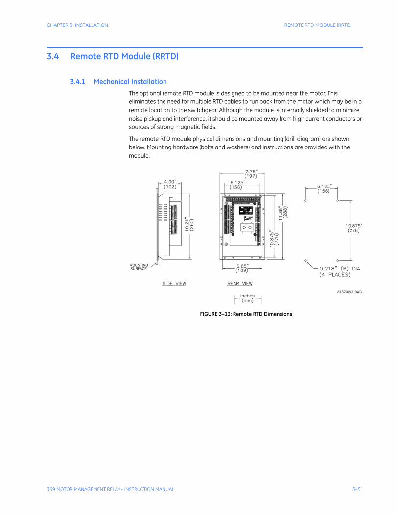
CHAPTER 3: INSTALLATION REMOTE RTD MODULE (RRTD)
369 MOTOR MANAGEMENT RELAY– INSTRUCTION MANUAL 3–51
3.4 Remote RTD Module (RRTD)
3.4.1 Mechanical InstallationThe optional remote RTD module is designed to be mounted near the motor. This eliminates the need for multiple RTD cables to run back from the motor which may be in a remote location to the switchgear. Although the module is internally shielded to minimize noise pickup and interference, it should be mounted away from high current conductors or sources of strong magnetic fields.
The remote RTD module physical dimensions and mounting (drill diagram) are shown below. Mounting hardware (bolts and washers) and instructions are provided with the module.
FIGURE 3–13: Remote RTD Dimensions
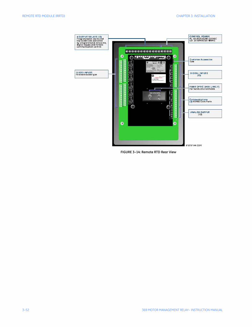
3–52 369 MOTOR MANAGEMENT RELAY– INSTRUCTION MANUAL
REMOTE RTD MODULE (RRTD) CHAPTER 3: INSTALLATION
FIGURE 3–14: Remote RTD Rear View

CHAPTER 3: INSTALLATION REMOTE RTD MODULE (RRTD)
369 MOTOR MANAGEMENT RELAY– INSTRUCTION MANUAL 3–53
3.4.2 Electrical Installation
FIGURE 3–15: Remote RTD Module
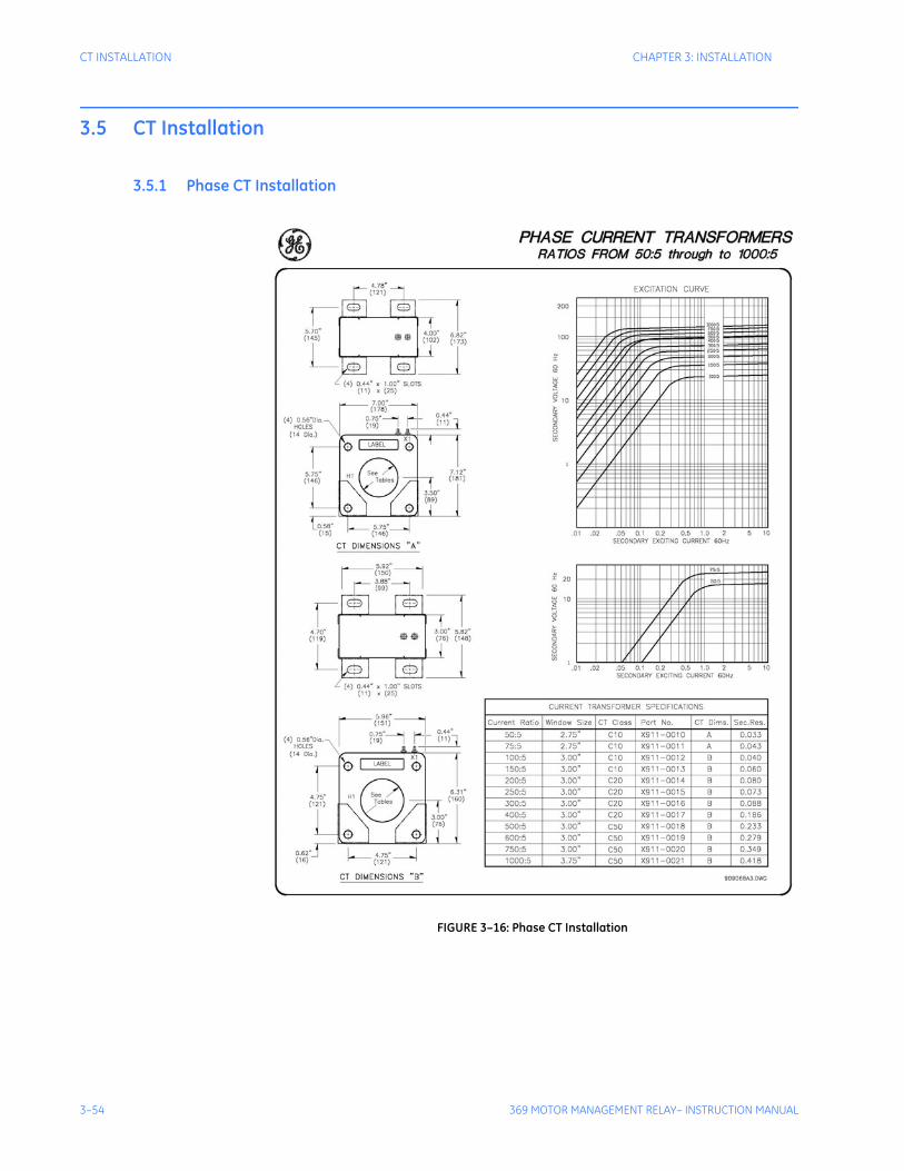
3–54 369 MOTOR MANAGEMENT RELAY– INSTRUCTION MANUAL
CT INSTALLATION CHAPTER 3: INSTALLATION
3.5 CT Installation
3.5.1 Phase CT Installation
FIGURE 3–16: Phase CT Installation
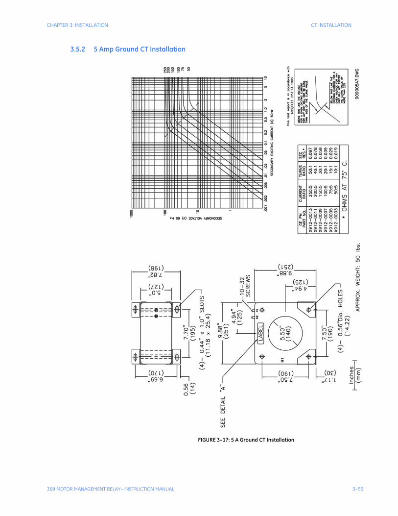
CHAPTER 3: INSTALLATION CT INSTALLATION
369 MOTOR MANAGEMENT RELAY– INSTRUCTION MANUAL 3–55
3.5.2 5 Amp Ground CT Installation
FIGURE 3–17: 5 A Ground CT Installation
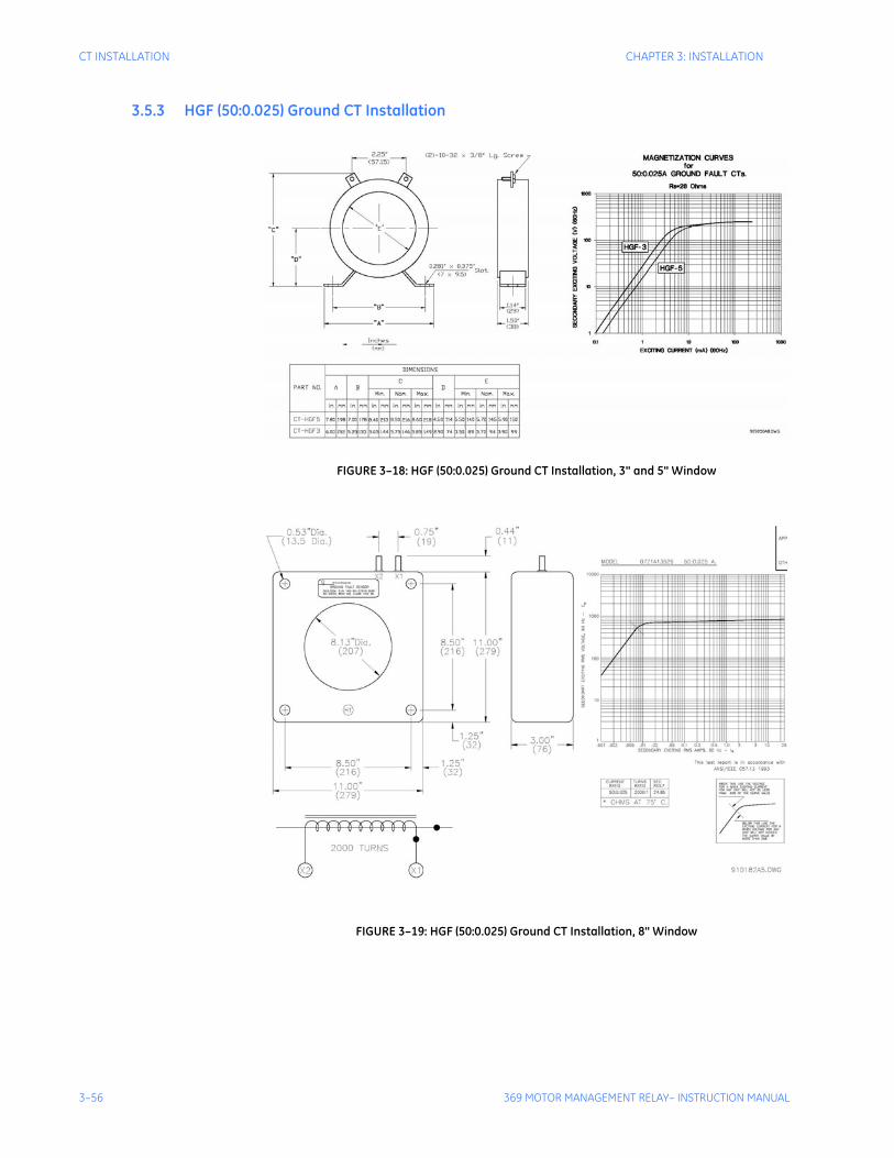
3–56 369 MOTOR MANAGEMENT RELAY– INSTRUCTION MANUAL
CT INSTALLATION CHAPTER 3: INSTALLATION
3.5.3 HGF (50:0.025) Ground CT Installation
FIGURE 3–18: HGF (50:0.025) Ground CT Installation, 3" and 5" Window
FIGURE 3–19: HGF (50:0.025) Ground CT Installation, 8" Window

369 MOTOR MANAGEMENT RELAY– INSTRUCTION MANUAL 4–57
369 Motor Management Relay
Chapter 4: User Interfaces
Digital EnergyMultilin
User Interfaces
4.1 Faceplate Interface
4.1.1 DisplayAll messages are displayed on a 40-character LCD display to make them visible under poor lighting conditions and from various viewing angles. Messages are displayed in plain English and do not require the aid of an instruction manual for deciphering. While the keypad and display are not actively being used, the display will default to user defined status messages. Any trip, alarm, or start inhibit will automatically override the default messages and appear on the display.
4.1.2 LED IndicatorsThere are ten LED indicators, as follows:
• TRIP: Trip relay has operated (energized)
• ALARM: Alarm relay has operated (energized)
• AUX 1: Auxiliary relay has operated (energized)
• AUX 2: Auxiliary relay has operated (energized)
• SERVICE: Relay in need of technical service.
• STOPPED: Motor is in the Stopped condition
• STARTING: Motor is in the Starting condition
• RUNNING: Motor is in the Running condition
• OVERLOAD: Motor is in the Overload condition
• LOCKOUT: Motor is in the Lockout condition
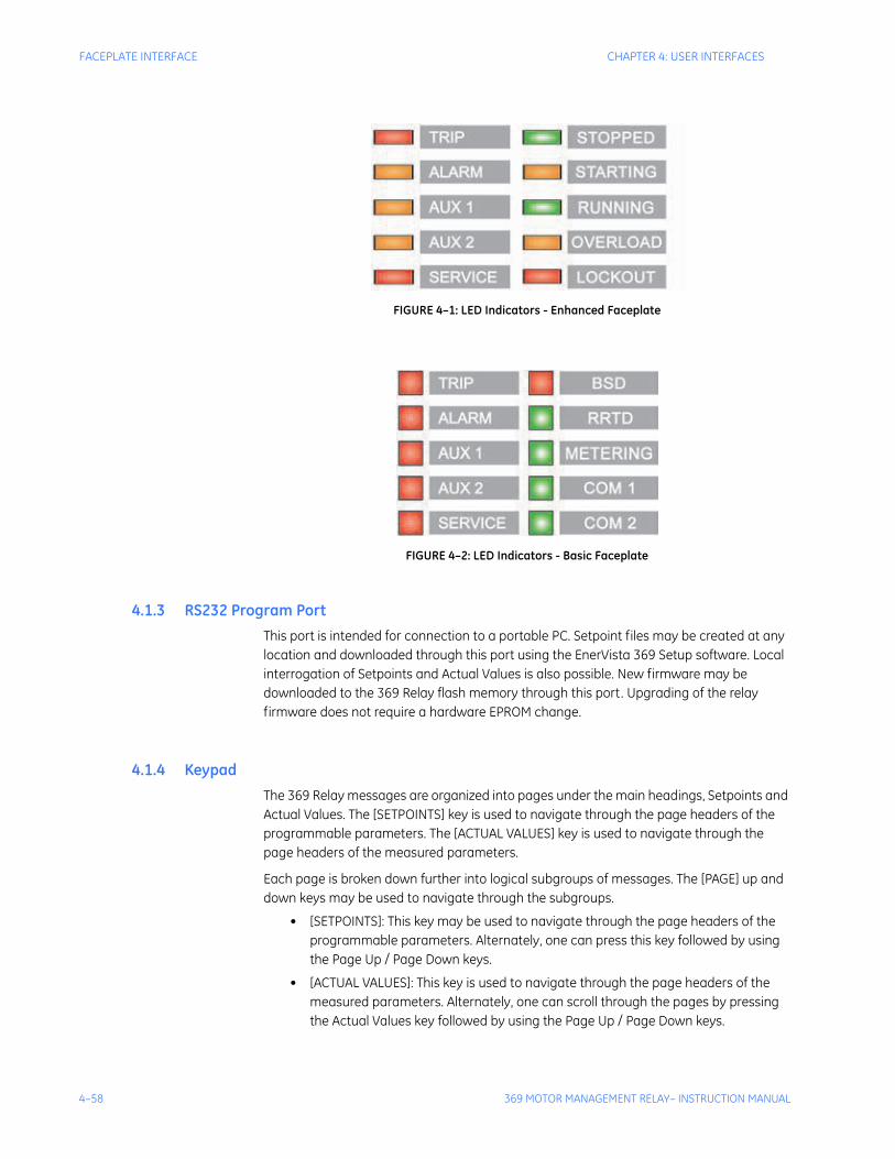
4–58 369 MOTOR MANAGEMENT RELAY– INSTRUCTION MANUAL
FACEPLATE INTERFACE CHAPTER 4: USER INTERFACES
FIGURE 4–1: LED Indicators - Enhanced Faceplate
FIGURE 4–2: LED Indicators - Basic Faceplate
4.1.3 RS232 Program PortThis port is intended for connection to a portable PC. Setpoint files may be created at any location and downloaded through this port using the EnerVista 369 Setup software. Local interrogation of Setpoints and Actual Values is also possible. New firmware may be downloaded to the 369 Relay flash memory through this port. Upgrading of the relay firmware does not require a hardware EPROM change.
4.1.4 KeypadThe 369 Relay messages are organized into pages under the main headings, Setpoints and Actual Values. The [SETPOINTS] key is used to navigate through the page headers of the programmable parameters. The [ACTUAL VALUES] key is used to navigate through the page headers of the measured parameters.
Each page is broken down further into logical subgroups of messages. The [PAGE] up and down keys may be used to navigate through the subgroups.
• [SETPOINTS]: This key may be used to navigate through the page headers of the programmable parameters. Alternately, one can press this key followed by using the Page Up / Page Down keys.
• [ACTUAL VALUES]: This key is used to navigate through the page headers of the measured parameters. Alternately, one can scroll through the pages by pressing the Actual Values key followed by using the Page Up / Page Down keys.

CHAPTER 4: USER INTERFACES FACEPLATE INTERFACE
369 MOTOR MANAGEMENT RELAY– INSTRUCTION MANUAL 4–59
• [PAGE]: The Page Up/ Page Down keys may be used to scroll through page headers for both Setpoints and Actual Values.
• [LINE]: Once the required page is found, the Line Up/ Line Down keys may be used to scroll through the sub-headings.
• [VALUE]: The Value Up and Value Down keys are used to scroll through variables in the Setpoint programming mode. It will increment and decrement numerical Setpoint values, or alter yes/no options.
• [RESET]: The reset key may be used to reset a trip or latched alarm, provided it has been activated by selecting the local reset.
• [ENTER] The key is dual purpose. It is used to enter the subgroups or store altered setpoint values.
• [CLEAR] The key is also dual purpose. It may be used to exit the subgroups or to return an altered setpoint to its original value before it has been stored.
• [HELP]: The help key may be pressed at any time for context sensitive help messages; such as the Setpoint range, etc.
To enter setpoints, select the desired page header. Then press the [LINE UP] / [LINE DOWN] keys to scroll through the page and find the desired subgroup. Once the desired subgroup is found, press the [VALUE UP] / [VALUE DOWN] keys to adjust the setpoints. Press the [ENTER] key to save the setpoint or the [CLEAR] key to revert back to the old setpoint.
4.1.5 Setpoint EntryIn order to store any setpoints, Terminals 57 and 58 (access terminals) must be shorted (a key switch may be used for security). There is also a Setpoint Passcode feature that may be enabled to restrict access to setpoints. The passcode must be entered to allow the changing of setpoint values. A passcode of 0 effectively turns off the passcode feature and only the access jumper is required for changing setpoints.
If no key is pressed for 30 minutes, access to setpoint values will be restricted until the passcode is entered again. To prevent setpoint access before the 30 minutes expires, the unit may be turned off and back on, the access jumper may be removed, or the SETPOINT ACCESS setpoint may be changed to Restricted. The passcode cannot be entered until terminals 57 and 58 (access terminals) are shorted.
Setpoint changes take effect immediately, even when motor is running. It is not recommended, however, to change setpoints while the motor is running as any mistake could cause a nuisance trip.
Refer to Section 5.2.1: Setpoint Access on page –111 for a detailed description of the setpoint access procedure.
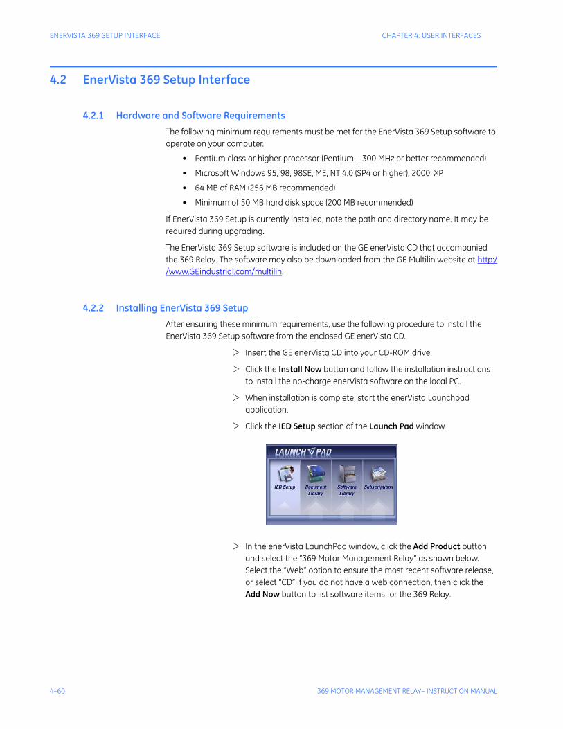
4–60 369 MOTOR MANAGEMENT RELAY– INSTRUCTION MANUAL
ENERVISTA 369 SETUP INTERFACE CHAPTER 4: USER INTERFACES
4.2 EnerVista 369 Setup Interface
4.2.1 Hardware and Software RequirementsThe following minimum requirements must be met for the EnerVista 369 Setup software to operate on your computer.
• Pentium class or higher processor (Pentium II 300 MHz or better recommended)
• Microsoft Windows 95, 98, 98SE, ME, NT 4.0 (SP4 or higher), 2000, XP
• 64 MB of RAM (256 MB recommended)
• Minimum of 50 MB hard disk space (200 MB recommended)
If EnerVista 369 Setup is currently installed, note the path and directory name. It may be required during upgrading.
The EnerVista 369 Setup software is included on the GE enerVista CD that accompanied the 369 Relay. The software may also be downloaded from the GE Multilin website at http://www.GEindustrial.com/multilin.
4.2.2 Installing EnerVista 369 SetupAfter ensuring these minimum requirements, use the following procedure to install the EnerVista 369 Setup software from the enclosed GE enerVista CD.
Insert the GE enerVista CD into your CD-ROM drive.
Click the Install Now button and follow the installation instructions to install the no-charge enerVista software on the local PC.
When installation is complete, start the enerVista Launchpad application.
Click the IED Setup section of the Launch Pad window.
In the enerVista LaunchPad window, click the Add Product button and select the “369 Motor Management Relay” as shown below. Select the “Web” option to ensure the most recent software release, or select “CD” if you do not have a web connection, then click the Add Now button to list software items for the 369 Relay.
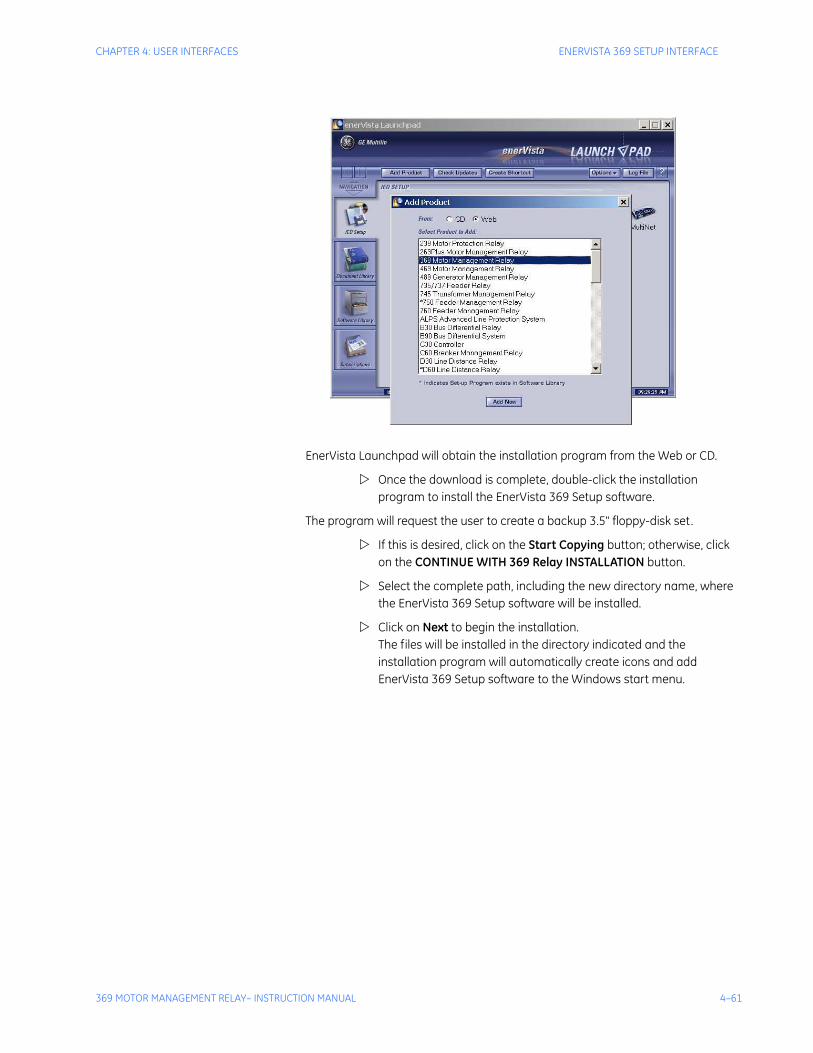
CHAPTER 4: USER INTERFACES ENERVISTA 369 SETUP INTERFACE
369 MOTOR MANAGEMENT RELAY– INSTRUCTION MANUAL 4–61
EnerVista Launchpad will obtain the installation program from the Web or CD.
Once the download is complete, double-click the installation program to install the EnerVista 369 Setup software.
The program will request the user to create a backup 3.5" floppy-disk set.
If this is desired, click on the Start Copying button; otherwise, click on the CONTINUE WITH 369 Relay INSTALLATION button.
Select the complete path, including the new directory name, where the EnerVista 369 Setup software will be installed.
Click on Next to begin the installation. The files will be installed in the directory indicated and the installation program will automatically create icons and add EnerVista 369 Setup software to the Windows start menu.
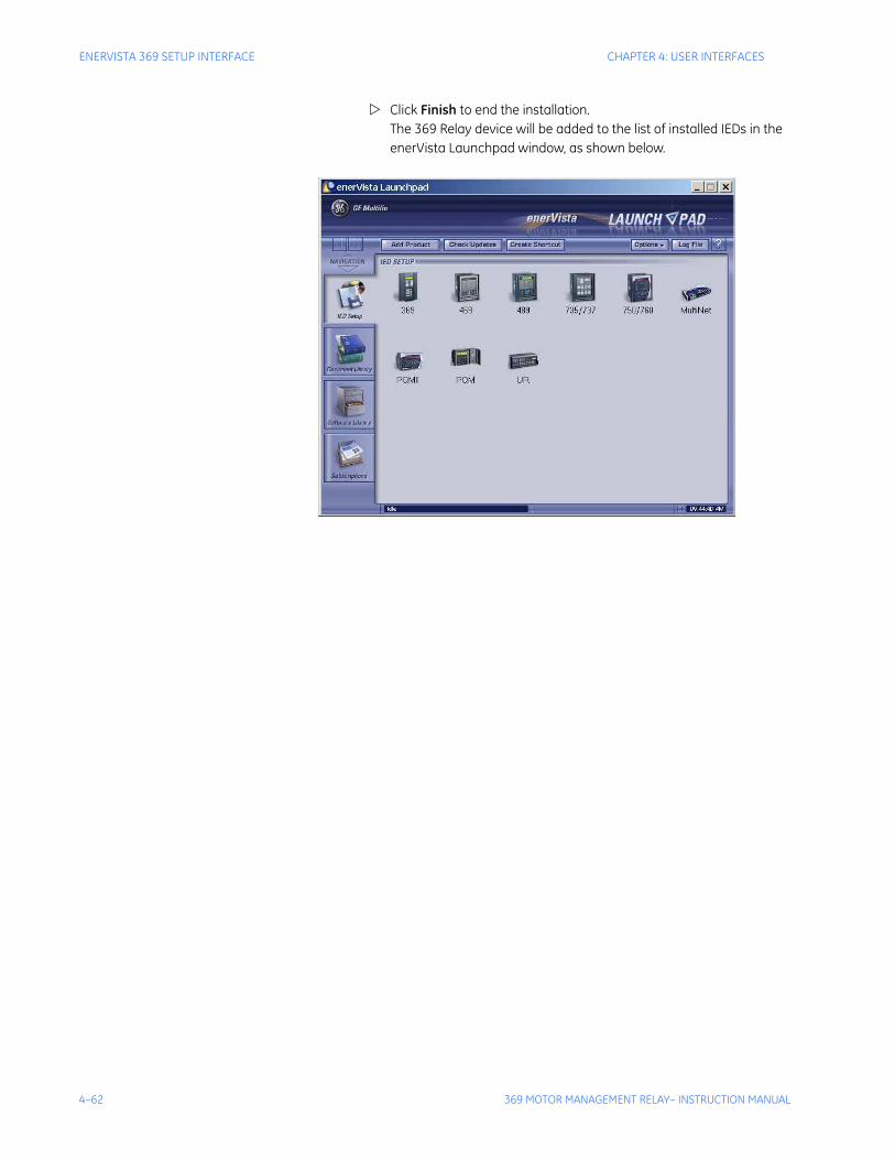
4–62 369 MOTOR MANAGEMENT RELAY– INSTRUCTION MANUAL
ENERVISTA 369 SETUP INTERFACE CHAPTER 4: USER INTERFACES
Click Finish to end the installation. The 369 Relay device will be added to the list of installed IEDs in the enerVista Launchpad window, as shown below.
CHAPTER 4: USER INTERFACES CONNECTING ENERVISTA 369 SETUP TO THE RELAY
369 MOTOR MANAGEMENT RELAY– INSTRUCTION MANUAL 4–63
4.3 Connecting EnerVista 369 Setup to the Relay
4.3.1 Configuring Serial CommunicationsBefore starting, verify that the serial cable is properly connected to either the RS232 port on the front panel of the device (for RS232 communications) or to the RS485 terminals on the back of the device (for RS485 communications).
This example demonstrates an RS232 connection. For RS485 communications, the GE Multilin F485 converter will be required. Refer to the F485 manual for additional details. To configure the relay for Ethernet communications, see Configuring Ethernet Communications on page 4–65.
Install and start the latest version of the EnerVista 369 Setup software (available from the GE enerVista CD). See the previous section for the installation procedure.
Click on the Device Setup button to open the Device Setup window.
Click the Add Site button to define a new site.
Enter the desired site name in the Site Name field. If desired, a short description of site can also be entered along with the display order of devices defined for the site. In this example, we will use “Substation 1” as the site name.
Click the OK button when complete.
The new site will appear in the upper-left list in the EnerVista 369 Setup window.
Click the Add Device button to define the new device.
Enter the desired name in the Device Name field and a description (optional) of the site.
Select “Serial” from the Interface drop-down list. This will display a number of interface parameters that must be entered for proper RS232 functionality.
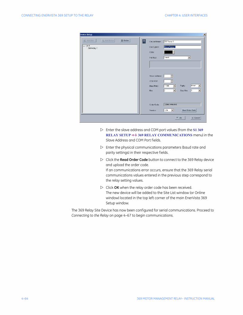
4–64 369 MOTOR MANAGEMENT RELAY– INSTRUCTION MANUAL
CONNECTING ENERVISTA 369 SETUP TO THE RELAY CHAPTER 4: USER INTERFACES
Enter the slave address and COM port values (from the S1 369 RELAY SETUP 369 RELAY COMMUNICATIONS menu) in the Slave Address and COM Port fields.
Enter the physical communications parameters (baud rate and parity settings) in their respective fields.
Click the Read Order Code button to connect to the 369 Relay device and upload the order code. If an communications error occurs, ensure that the 369 Relay serial communications values entered in the previous step correspond to the relay setting values.
Click OK when the relay order code has been received. The new device will be added to the Site List window (or Online window) located in the top left corner of the main EnerVista 369 Setup window.
The 369 Relay Site Device has now been configured for serial communications. Proceed to Connecting to the Relay on page 4–67 to begin communications.
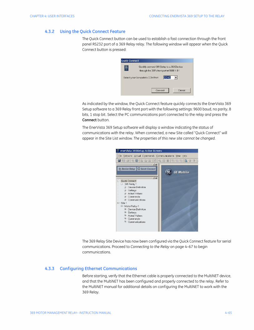
CHAPTER 4: USER INTERFACES CONNECTING ENERVISTA 369 SETUP TO THE RELAY
369 MOTOR MANAGEMENT RELAY– INSTRUCTION MANUAL 4–65
4.3.2 Using the Quick Connect FeatureThe Quick Connect button can be used to establish a fast connection through the front panel RS232 port of a 369 Relay relay. The following window will appear when the Quick Connect button is pressed:
As indicated by the window, the Quick Connect feature quickly connects the EnerVista 369 Setup software to a 369 Relay front port with the following settings: 9600 baud, no parity, 8 bits, 1 stop bit. Select the PC communications port connected to the relay and press the Connect button.
The EnerVista 369 Setup software will display a window indicating the status of communications with the relay. When connected, a new Site called “Quick Connect” will appear in the Site List window. The properties of this new site cannot be changed.
The 369 Relay Site Device has now been configured via the Quick Connect feature for serial communications. Proceed to Connecting to the Relay on page 4–67 to begin communications.
4.3.3 Configuring Ethernet CommunicationsBefore starting, verify that the Ethernet cable is properly connected to the MultiNET device, and that the MultiNET has been configured and properly connected to the relay. Refer to the MultiNET manual for additional details on configuring the MultiNET to work with the 369 Relay.
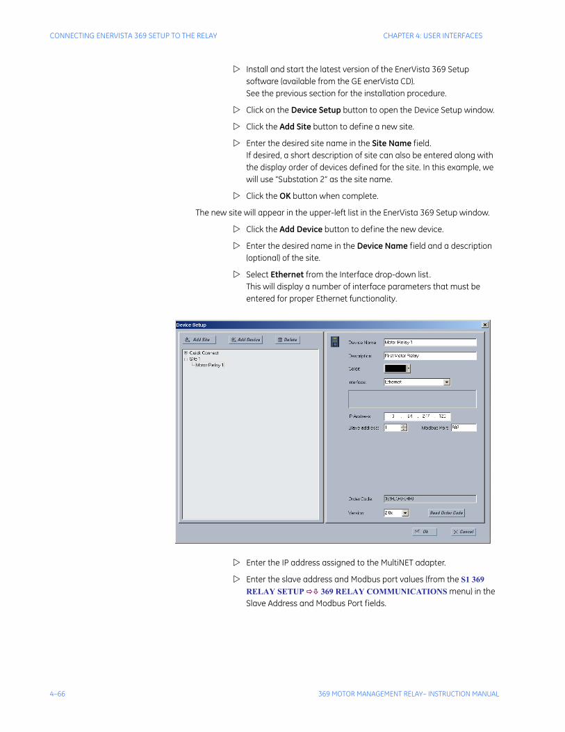
4–66 369 MOTOR MANAGEMENT RELAY– INSTRUCTION MANUAL
CONNECTING ENERVISTA 369 SETUP TO THE RELAY CHAPTER 4: USER INTERFACES
Install and start the latest version of the EnerVista 369 Setup software (available from the GE enerVista CD). See the previous section for the installation procedure.
Click on the Device Setup button to open the Device Setup window.
Click the Add Site button to define a new site.
Enter the desired site name in the Site Name field. If desired, a short description of site can also be entered along with the display order of devices defined for the site. In this example, we will use “Substation 2” as the site name.
Click the OK button when complete.
The new site will appear in the upper-left list in the EnerVista 369 Setup window.
Click the Add Device button to define the new device.
Enter the desired name in the Device Name field and a description (optional) of the site.
Select Ethernet from the Interface drop-down list. This will display a number of interface parameters that must be entered for proper Ethernet functionality.
Enter the IP address assigned to the MultiNET adapter.
Enter the slave address and Modbus port values (from the S1 369 RELAY SETUP 369 RELAY COMMUNICATIONS menu) in the Slave Address and Modbus Port fields.

CHAPTER 4: USER INTERFACES CONNECTING ENERVISTA 369 SETUP TO THE RELAY
369 MOTOR MANAGEMENT RELAY– INSTRUCTION MANUAL 4–67
Click the Read Order Code button to connect to the 369 Relay device and upload the order code. If an communications error occurs, ensure that the 369 Relay Ethernet communications values entered in the previous step correspond to the relay and MultiNET setting values.
Click OK when the relay order code has been received. The new device will be added to the Site List window (or Online window) located in the top left corner of the main EnerVista 369 Setup window.
The 369 Relay Site Device has now been configured for Ethernet communications. Proceed to the following section to begin communications.
4.3.4 Connecting to the RelayNow that the communications parameters have been properly configured, the user can easily connect to the relay.
Expand the Site list by double clicking on the site name or clicking on the «+» box to list the available devices for the given site (for example, in the “Substation 1” site shown below).
Desired device trees can be expanded by clicking the «+» box. The following list of headers is shown for each device:
• Device Definitions• Settings• Actual Values• Commands• Communications
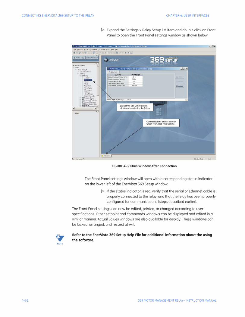
4–68 369 MOTOR MANAGEMENT RELAY– INSTRUCTION MANUAL
CONNECTING ENERVISTA 369 SETUP TO THE RELAY CHAPTER 4: USER INTERFACES
Expand the Settings > Relay Setup list item and double click on Front Panel to open the Front Panel settings window as shown below:
FIGURE 4–3: Main Window After Connection
The Front Panel settings window will open with a corresponding status indicator on the lower left of the EnerVista 369 Setup window.
If the status indicator is red, verify that the serial or Ethernet cable is properly connected to the relay, and that the relay has been properly configured for communications (steps described earlier).
The Front Panel settings can now be edited, printed, or changed according to user specifications. Other setpoint and commands windows can be displayed and edited in a similar manner. Actual values windows are also available for display. These windows can be locked, arranged, and resized at will.
Note Refer to the EnerVista 369 Setup Help File for additional information about the using the software.
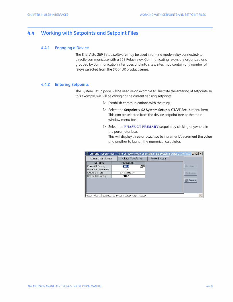
CHAPTER 4: USER INTERFACES WORKING WITH SETPOINTS AND SETPOINT FILES
369 MOTOR MANAGEMENT RELAY– INSTRUCTION MANUAL 4–69
4.4 Working with Setpoints and Setpoint Files
4.4.1 Engaging a DeviceThe EnerVista 369 Setup software may be used in on-line mode (relay connected) to directly communicate with a 369 Relay relay. Communicating relays are organized and grouped by communication interfaces and into sites. Sites may contain any number of relays selected from the SR or UR product series.
4.4.2 Entering SetpointsThe System Setup page will be used as an example to illustrate the entering of setpoints. In this example, we will be changing the current sensing setpoints.
Establish communications with the relay.
Select the Setpoint > S2 System Setup > CT/VT Setup menu item. This can be selected from the device setpoint tree or the main window menu bar.
Select the PHASE CT PRIMARY setpoint by clicking anywhere in the parameter box. This will display three arrows: two to increment/decrement the value and another to launch the numerical calculator.
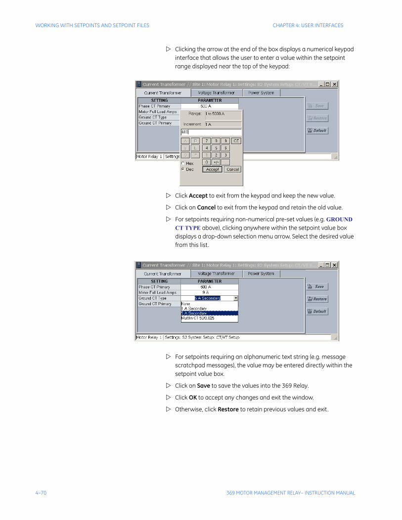
4–70 369 MOTOR MANAGEMENT RELAY– INSTRUCTION MANUAL
WORKING WITH SETPOINTS AND SETPOINT FILES CHAPTER 4: USER INTERFACES
Clicking the arrow at the end of the box displays a numerical keypad interface that allows the user to enter a value within the setpoint range displayed near the top of the keypad:
Click Accept to exit from the keypad and keep the new value.
Click on Cancel to exit from the keypad and retain the old value.
For setpoints requiring non-numerical pre-set values (e.g. GROUND CT TYPE above), clicking anywhere within the setpoint value box displays a drop-down selection menu arrow. Select the desired value from this list.
For setpoints requiring an alphanumeric text string (e.g. message scratchpad messages), the value may be entered directly within the setpoint value box.
Click on Save to save the values into the 369 Relay.
Click OK to accept any changes and exit the window.
Otherwise, click Restore to retain previous values and exit.
CHAPTER 4: USER INTERFACES WORKING WITH SETPOINTS AND SETPOINT FILES
369 MOTOR MANAGEMENT RELAY– INSTRUCTION MANUAL 4–71
4.4.3 File SupportOpening any EnerVista 369 Setup file will automatically launch the application or provide focus to the already opened application. If the file is a settings file (has a ‘369 Relay’ extension) which had been removed from the Settings List tree menu, it will be added back to the Settings List tree.
New files will be automatically added to the tree, which is sorted alphabetically with respect to settings file names.
4.4.4 Using Setpoints Files
Overview
The EnerVista 369 Setup software interface supports three ways of handling changes to relay settings:
• In off-line mode (relay disconnected) to create or edit relay settings files for later download to communicating relays.
• Directly modifying relay settings while connected to a communicating relay, then saving the settings when complete.
• Creating/editing settings files while connected to a communicating relay, then saving them to the relay when complete.
Settings files are organized on the basis of file names assigned by the user. A settings file contains data pertaining to the following categories of relay settings:
• Device Definition
• Product Setup
• System Setup
• Grouped Elements
• Control Elements
• Inputs/Outputs
• Testing
Factory default values are supplied and can be restored after any changes.
The EnerVista 369 Setup software displays relay setpoints with the same hierarchy as the front panel display. For specific details on setpoints, refer to Chapter 5.
Downloading and Saving Setpoints Files
Setpoints must be saved to a file on the local PC before performing any firmware upgrades. Saving setpoints is also highly recommended before making any setpoint changes or creating new setpoint files.
The EnerVista 369 Setup window, setpoint files are accessed in the Settings List control bar window or the Files Window. Use the following procedure to download and save setpoint files to a local PC.
Ensure that the site and corresponding device(s) have been properly defined and configured as shown in Connecting EnerVista 369 Setup to the Relay on page 4–63.
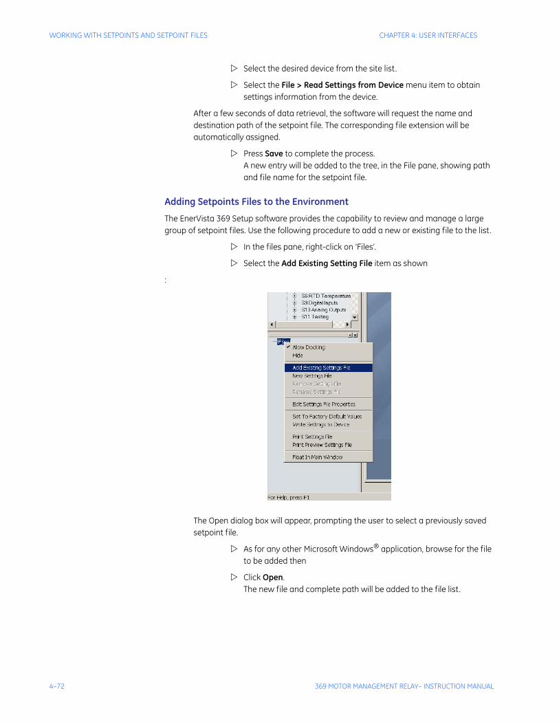
4–72 369 MOTOR MANAGEMENT RELAY– INSTRUCTION MANUAL
WORKING WITH SETPOINTS AND SETPOINT FILES CHAPTER 4: USER INTERFACES
Select the desired device from the site list.
Select the File > Read Settings from Device menu item to obtain settings information from the device.
After a few seconds of data retrieval, the software will request the name and destination path of the setpoint file. The corresponding file extension will be automatically assigned.
Press Save to complete the process. A new entry will be added to the tree, in the File pane, showing path and file name for the setpoint file.
Adding Setpoints Files to the Environment
The EnerVista 369 Setup software provides the capability to review and manage a large group of setpoint files. Use the following procedure to add a new or existing file to the list.
In the files pane, right-click on ‘Files’.
Select the Add Existing Setting File item as shown
:
The Open dialog box will appear, prompting the user to select a previously saved setpoint file.
As for any other Microsoft Windows® application, browse for the file to be added then
Click Open. The new file and complete path will be added to the file list.
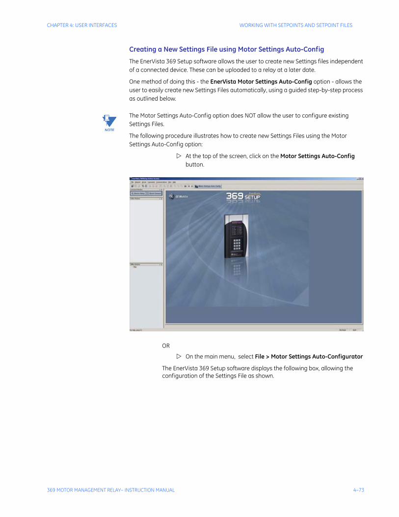
CHAPTER 4: USER INTERFACES WORKING WITH SETPOINTS AND SETPOINT FILES
369 MOTOR MANAGEMENT RELAY– INSTRUCTION MANUAL 4–73
Creating a New Settings File using Motor Settings Auto-Config
The EnerVista 369 Setup software allows the user to create new Settings files independent of a connected device. These can be uploaded to a relay at a later date.
One method of doing this - the EnerVista Motor Settings Auto-Config option - allows the user to easily create new Settings Files automatically, using a guided step-by-step process as outlined below.
Note The Motor Settings Auto-Config option does NOT allow the user to configure existing Settings Files.
The following procedure illustrates how to create new Settings Files using the Motor Settings Auto-Config option:
At the top of the screen, click on the Motor Settings Auto-Config button.
OR
On the main menu, select File > Motor Settings Auto-Configurator
The EnerVista 369 Setup software displays the following box, allowing the configuration of the Settings File as shown.
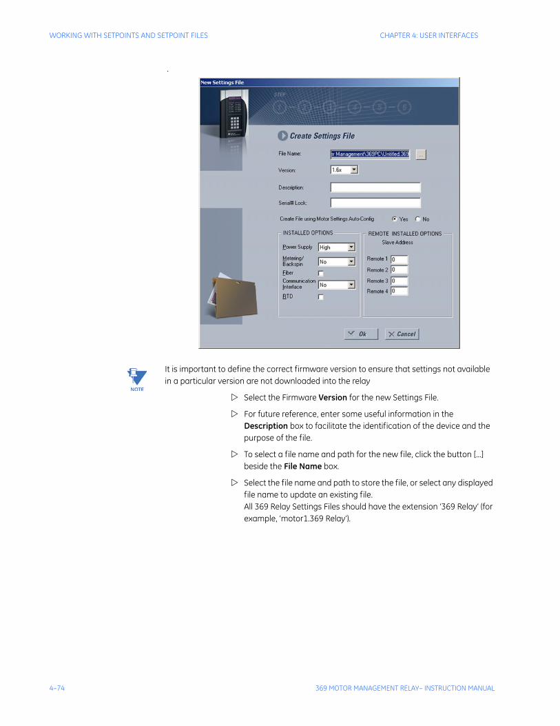
4–74 369 MOTOR MANAGEMENT RELAY– INSTRUCTION MANUAL
WORKING WITH SETPOINTS AND SETPOINT FILES CHAPTER 4: USER INTERFACES
.
Note It is important to define the correct firmware version to ensure that settings not available in a particular version are not downloaded into the relay
Select the Firmware Version for the new Settings File.
For future reference, enter some useful information in the Description box to facilitate the identification of the device and the purpose of the file.
To select a file name and path for the new file, click the button [...] beside the File Name box.
Select the file name and path to store the file, or select any displayed file name to update an existing file. All 369 Relay Settings Files should have the extension ‘369 Relay’ (for example, ‘motor1.369 Relay’).
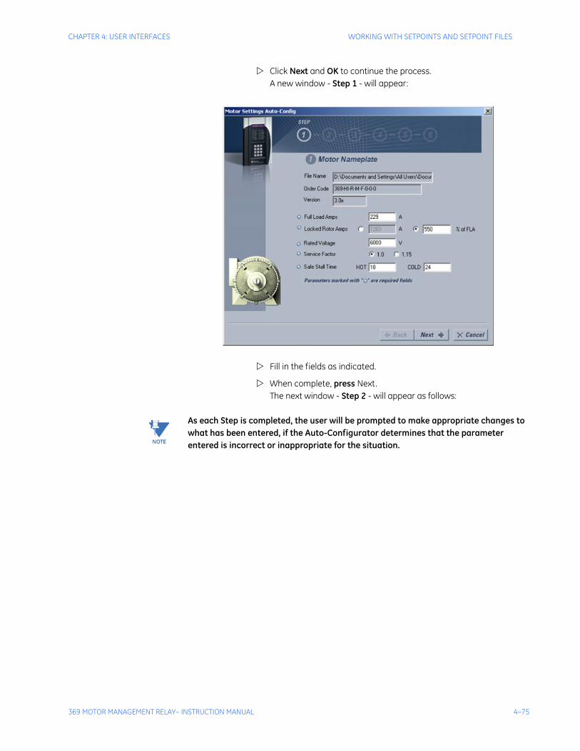
CHAPTER 4: USER INTERFACES WORKING WITH SETPOINTS AND SETPOINT FILES
369 MOTOR MANAGEMENT RELAY– INSTRUCTION MANUAL 4–75
Click Next and OK to continue the process. A new window - Step 1 - will appear:
Fill in the fields as indicated.
When complete, press Next.The next window - Step 2 - will appear as follows:
Note As each Step is completed, the user will be prompted to make appropriate changes to what has been entered, if the Auto-Configurator determines that the parameter entered is incorrect or inappropriate for the situation.
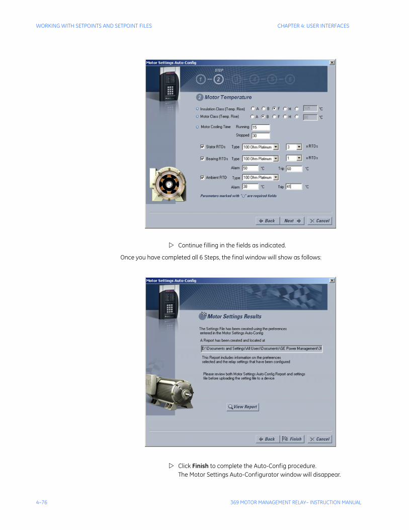
4–76 369 MOTOR MANAGEMENT RELAY– INSTRUCTION MANUAL
WORKING WITH SETPOINTS AND SETPOINT FILES CHAPTER 4: USER INTERFACES
Continue filling in the fields as indicated.
Once you have completed all 6 Steps, the final window will show as follows:
Click Finish to complete the Auto-Config procedure.The Motor Settings Auto-Configurator window will disappear.

CHAPTER 4: USER INTERFACES WORKING WITH SETPOINTS AND SETPOINT FILES
369 MOTOR MANAGEMENT RELAY– INSTRUCTION MANUAL 4–77
A new Settings File containing the parameters you have just input will appear in the Files pane as shown:
Creating a New Settings File without using Motor Settings Auto-Config
The EnerVista 369 Setup software allows the user to create new Settings files independent of a connected device. These can be uploaded to a relay at a later date. The following manual procedure - as distinct from the Motor Settings Auto-Config option described above - illustrates how to create new Settings Files.
In the File pane, right click on File.
Select the New Settings File item. The EnerVista 369 Setup software displays the following window, allowing the configuration of the Settings File as shown below.
Note Note that this window allows you to choose between creating your Settings File manually or using the Motor Settings Auto-Configurator as detailed above.

4–78 369 MOTOR MANAGEMENT RELAY– INSTRUCTION MANUAL
WORKING WITH SETPOINTS AND SETPOINT FILES CHAPTER 4: USER INTERFACES
Note It is important to define the correct firmware version to ensure that settings not available in a particular version are not downloaded into the relay
Select the Firmware Version for the new Settings File.
For future reference, enter some useful information in the Description box to facilitate the identification of the device and the purpose of the file.
To select a file name and path for the new file, click the button beside the File Name box [...].
Select the file name and path to store the file, or select any displayed file name to update an existing file. All 369 Relay Settings Files should have the extension ‘369 Relay’ (for example, ‘motor1.369 Relay’).
Click the appropriate radio button (yes or no) to choose between Auto-Configurator or manual creation of the Settings File.
Click OK to complete the process. Once this step is completed, the new file, with a complete path, will be added to the EnerVista 369 Setup software environment.
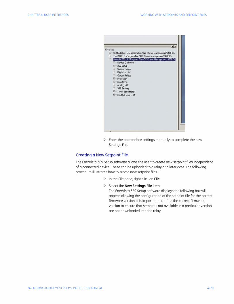
CHAPTER 4: USER INTERFACES WORKING WITH SETPOINTS AND SETPOINT FILES
369 MOTOR MANAGEMENT RELAY– INSTRUCTION MANUAL 4–79
Enter the appropriate settings manually to complete the new Settings File.
Creating a New Setpoint File
The EnerVista 369 Setup software allows the user to create new setpoint files independent of a connected device. These can be uploaded to a relay at a later date. The following procedure illustrates how to create new setpoint files.
In the File pane, right click on File.
Select the New Settings File item. The EnerVista 369 Setup software displays the following box will appear, allowing the configuration of the setpoint file for the correct firmware version. It is important to define the correct firmware version to ensure that setpoints not available in a particular version are not downloaded into the relay.
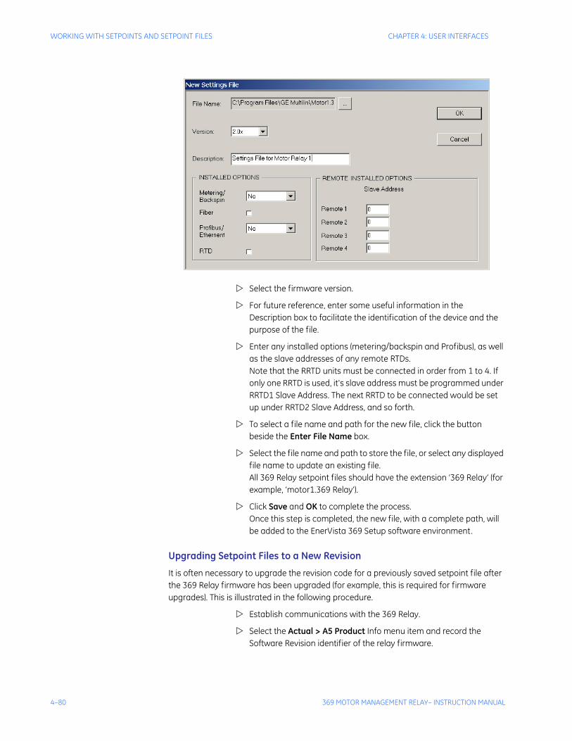
4–80 369 MOTOR MANAGEMENT RELAY– INSTRUCTION MANUAL
WORKING WITH SETPOINTS AND SETPOINT FILES CHAPTER 4: USER INTERFACES
Select the firmware version.
For future reference, enter some useful information in the Description box to facilitate the identification of the device and the purpose of the file.
Enter any installed options (metering/backspin and Profibus), as well as the slave addresses of any remote RTDs.Note that the RRTD units must be connected in order from 1 to 4. If only one RRTD is used, it's slave address must be programmed under RRTD1 Slave Address. The next RRTD to be connected would be set up under RRTD2 Slave Address, and so forth.
To select a file name and path for the new file, click the button beside the Enter File Name box.
Select the file name and path to store the file, or select any displayed file name to update an existing file. All 369 Relay setpoint files should have the extension ‘369 Relay’ (for example, ‘motor1.369 Relay’).
Click Save and OK to complete the process. Once this step is completed, the new file, with a complete path, will be added to the EnerVista 369 Setup software environment.
Upgrading Setpoint Files to a New Revision
It is often necessary to upgrade the revision code for a previously saved setpoint file after the 369 Relay firmware has been upgraded (for example, this is required for firmware upgrades). This is illustrated in the following procedure.
Establish communications with the 369 Relay.
Select the Actual > A5 Product Info menu item and record the Software Revision identifier of the relay firmware.
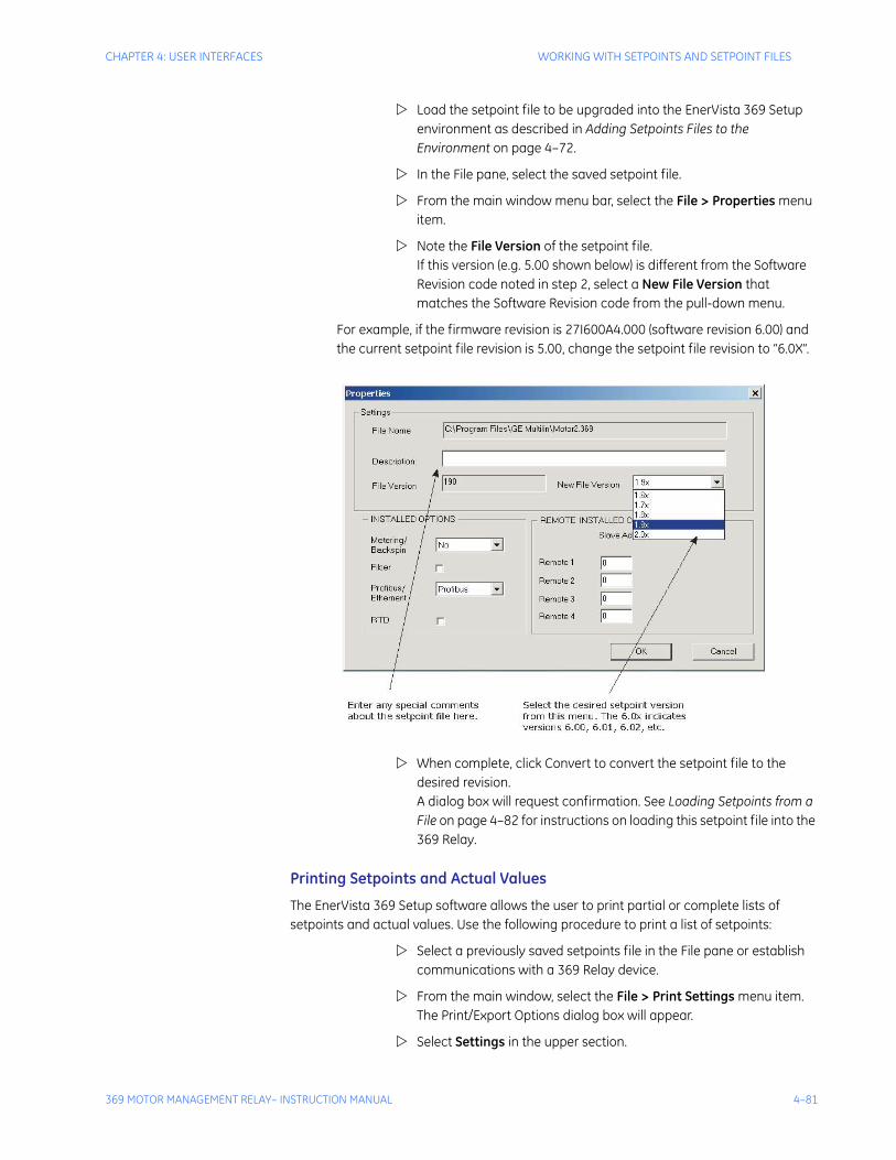
CHAPTER 4: USER INTERFACES WORKING WITH SETPOINTS AND SETPOINT FILES
369 MOTOR MANAGEMENT RELAY– INSTRUCTION MANUAL 4–81
Load the setpoint file to be upgraded into the EnerVista 369 Setup environment as described in Adding Setpoints Files to the Environment on page 4–72.
In the File pane, select the saved setpoint file.
From the main window menu bar, select the File > Properties menu item.
Note the File Version of the setpoint file. If this version (e.g. 5.00 shown below) is different from the Software Revision code noted in step 2, select a New File Version that matches the Software Revision code from the pull-down menu.
For example, if the firmware revision is 27I600A4.000 (software revision 6.00) and the current setpoint file revision is 5.00, change the setpoint file revision to “6.0X”.
When complete, click Convert to convert the setpoint file to the desired revision. A dialog box will request confirmation. See Loading Setpoints from a File on page 4–82 for instructions on loading this setpoint file into the 369 Relay.
Printing Setpoints and Actual Values
The EnerVista 369 Setup software allows the user to print partial or complete lists of setpoints and actual values. Use the following procedure to print a list of setpoints:
Select a previously saved setpoints file in the File pane or establish communications with a 369 Relay device.
From the main window, select the File > Print Settings menu item.The Print/Export Options dialog box will appear.
Select Settings in the upper section.
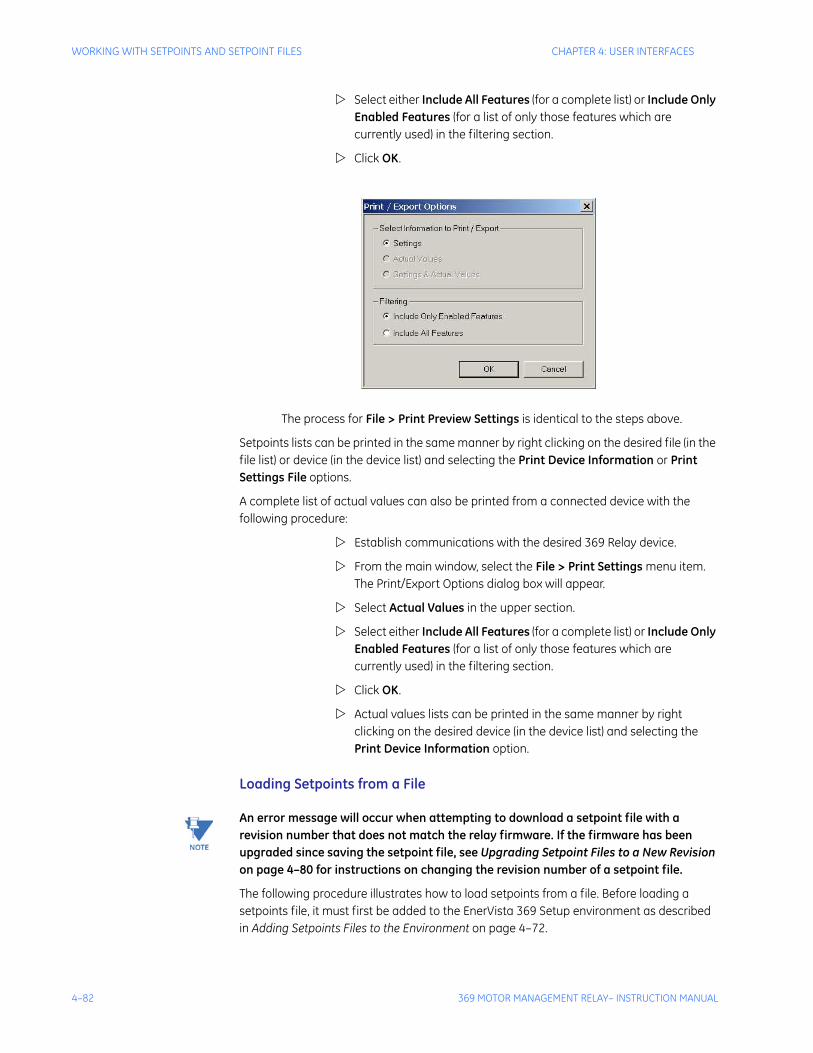
4–82 369 MOTOR MANAGEMENT RELAY– INSTRUCTION MANUAL
WORKING WITH SETPOINTS AND SETPOINT FILES CHAPTER 4: USER INTERFACES
Select either Include All Features (for a complete list) or Include Only Enabled Features (for a list of only those features which are currently used) in the filtering section.
Click OK.
The process for File > Print Preview Settings is identical to the steps above.
Setpoints lists can be printed in the same manner by right clicking on the desired file (in the file list) or device (in the device list) and selecting the Print Device Information or Print Settings File options.
A complete list of actual values can also be printed from a connected device with the following procedure:
Establish communications with the desired 369 Relay device.
From the main window, select the File > Print Settings menu item.The Print/Export Options dialog box will appear.
Select Actual Values in the upper section.
Select either Include All Features (for a complete list) or Include Only Enabled Features (for a list of only those features which are currently used) in the filtering section.
Click OK.
Actual values lists can be printed in the same manner by right clicking on the desired device (in the device list) and selecting the Print Device Information option.
Loading Setpoints from a File
Note An error message will occur when attempting to download a setpoint file with a revision number that does not match the relay firmware. If the firmware has been upgraded since saving the setpoint file, see Upgrading Setpoint Files to a New Revision on page 4–80 for instructions on changing the revision number of a setpoint file.
The following procedure illustrates how to load setpoints from a file. Before loading a setpoints file, it must first be added to the EnerVista 369 Setup environment as described in Adding Setpoints Files to the Environment on page 4–72.

CHAPTER 4: USER INTERFACES WORKING WITH SETPOINTS AND SETPOINT FILES
369 MOTOR MANAGEMENT RELAY– INSTRUCTION MANUAL 4–83
Select the previously saved setpoints file from the File pane of the EnerVista 369 Setup software main window.
Select the File > Properties menu item and verify that the corresponding file is fully compatible with the hardware and firmware version of the target relay. If the versions are not identical, see Upgrading Setpoint Files to a New Revision on page 4–80 for details on changing the setpoints file version.
Right-click on the selected file.
Select the Write Settings to Device item.
Select the target relay from the list of devices shown.
Click Send. If there is an incompatibility, an error will occur: If there are no incompatibilities between the target device and the settings file, the data will be transferred to the relay. An indication of the percentage completed will be shown in the bottom of the main window.
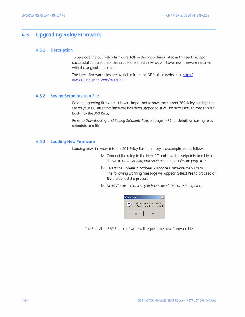
4–84 369 MOTOR MANAGEMENT RELAY– INSTRUCTION MANUAL
UPGRADING RELAY FIRMWARE CHAPTER 4: USER INTERFACES
4.5 Upgrading Relay Firmware
4.5.1 DescriptionTo upgrade the 369 Relay firmware, follow the procedures listed in this section. Upon successful completion of this procedure, the 369 Relay will have new firmware installed with the original setpoints.
The latest firmware files are available from the GE Multilin website at http://www.GEindustrial.com/multilin.
4.5.2 Saving Setpoints to a FileBefore upgrading firmware, it is very important to save the current 369 Relay settings to a file on your PC. After the firmware has been upgraded, it will be necessary to load this file back into the 369 Relay.
Refer to Downloading and Saving Setpoints Files on page 4–71 for details on saving relay setpoints to a file.
4.5.3 Loading New FirmwareLoading new firmware into the 369 Relay flash memory is accomplished as follows:
Connect the relay to the local PC and save the setpoints to a file as shown in Downloading and Saving Setpoints Files on page 4–71.
Select the Communications > Update Firmware menu item.The following warning message will appear: Select Yes to proceed or No the cancel the process.
Do NOT proceed unless you have saved the current setpoints.
The EnerVista 369 Setup software will request the new firmware file.
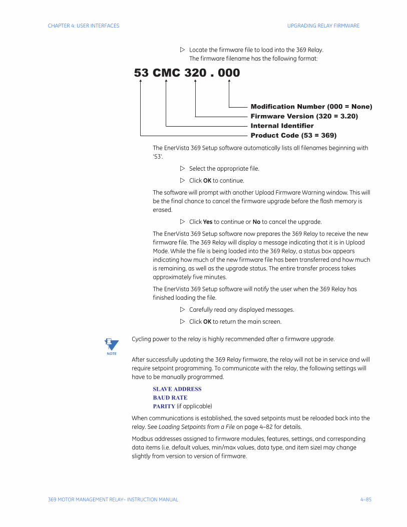
CHAPTER 4: USER INTERFACES UPGRADING RELAY FIRMWARE
369 MOTOR MANAGEMENT RELAY– INSTRUCTION MANUAL 4–85
Locate the firmware file to load into the 369 Relay. The firmware filename has the following format:
The EnerVista 369 Setup software automatically lists all filenames beginning with ‘53’.
Select the appropriate file.
Click OK to continue.
The software will prompt with another Upload Firmware Warning window. This will be the final chance to cancel the firmware upgrade before the flash memory is erased.
Click Yes to continue or No to cancel the upgrade.
The EnerVista 369 Setup software now prepares the 369 Relay to receive the new firmware file. The 369 Relay will display a message indicating that it is in Upload Mode. While the file is being loaded into the 369 Relay, a status box appears indicating how much of the new firmware file has been transferred and how much is remaining, as well as the upgrade status. The entire transfer process takes approximately five minutes.
The EnerVista 369 Setup software will notify the user when the 369 Relay has finished loading the file.
Carefully read any displayed messages.
Click OK to return the main screen.
Note Cycling power to the relay is highly recommended after a firmware upgrade.
After successfully updating the 369 Relay firmware, the relay will not be in service and will require setpoint programming. To communicate with the relay, the following settings will have to be manually programmed.
SLAVE ADDRESSBAUD RATEPARITY (if applicable)
When communications is established, the saved setpoints must be reloaded back into the relay. See Loading Setpoints from a File on page 4–82 for details.
Modbus addresses assigned to firmware modules, features, settings, and corresponding data items (i.e. default values, min/max values, data type, and item size) may change slightly from version to version of firmware.
53 CMC 320 . 000
Modification Number (000 = None)
Firmware Version (320 = 3.20)
Internal Identifier
Product Code (53 = 369)

4–86 369 MOTOR MANAGEMENT RELAY– INSTRUCTION MANUAL
UPGRADING RELAY FIRMWARE CHAPTER 4: USER INTERFACES
The addresses are rearranged when new features are added or existing features are enhanced or modified. The EEPROM DATA ERROR message displayed after upgrading/downgrading the firmware is a resettable, self-test message intended to inform users that the Modbus addresses have changed with the upgraded firmware. This message does not signal any problems when appearing after firmware upgrades.
CHAPTER 4: USER INTERFACES ADVANCED ENERVISTA 369 SETUP FEATURES
369 MOTOR MANAGEMENT RELAY– INSTRUCTION MANUAL 4–87
4.6 Advanced EnerVista 369 Setup Features
4.6.1 Triggered EventsWhile the interface is in either on-line or off-line mode, data generated by triggered specified parameters can be viewed and analyzed via one of the following features:
• Event Recorder: The event recorder captures contextual data associated with the last 512 events, listed in chronological order from most recent to the oldest.
• Oscillography: The oscillography waveform traces and digital states provide a visual display of power system and relay operation data captured during specific triggered events.
4.6.2 TrendingTrending from the 369 Relay is accomplished via EnerVista 369 Setup. Many different parameters can be trended and graphed at sampling periods from 1 second up to 1 hour. The parameters which can be trended by EnerVista 369 Setup are:
• Currents/Voltages: phase currents A/B/C; average phase current; motor load; current unbalance; ground current; and voltages Vab, Vbc, Vca Van, Vbn and Vcn
• Power: power factor; real power (kW); reactive power (kvar); Apparent Power (kVA); positive watthours; positive varhours; and negative varhours
• Temperature: Hottest Stator RTD; RTDs 1 through 12; and RRTDs 1 through 12
• Other: thermal capacity used and system frequency
To use the Trending function, run the EnerVista 369 Setup software and establish communications with a connected 369 Relay unit.
Select the Actual > Trending menu item to open the Trending window.
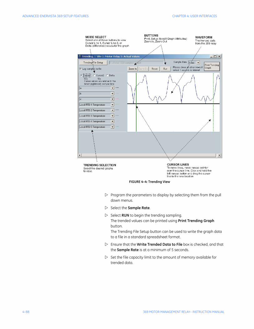
4–88 369 MOTOR MANAGEMENT RELAY– INSTRUCTION MANUAL
ADVANCED ENERVISTA 369 SETUP FEATURES CHAPTER 4: USER INTERFACES
FIGURE 4–4: Trending View
Program the parameters to display by selecting them from the pull down menus.
Select the Sample Rate.
Select RUN to begin the trending sampling.The trended values can be printed using Print Trending Graph button.The Trending File Setup button can be used to write the graph data to a file in a standard spreadsheet format.
Ensure that the Write Trended Data to File box is checked, and that the Sample Rate is at a minimum of 5 seconds.
Set the file capacity limit to the amount of memory available for trended data.
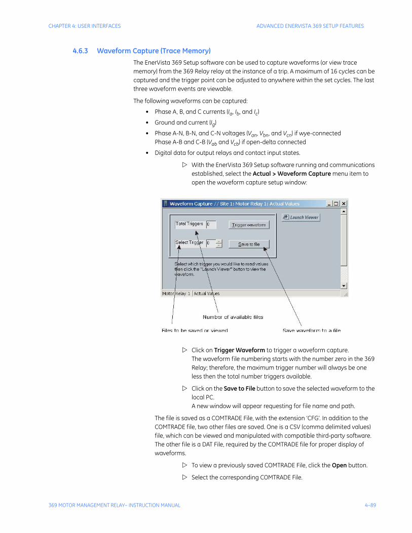
CHAPTER 4: USER INTERFACES ADVANCED ENERVISTA 369 SETUP FEATURES
369 MOTOR MANAGEMENT RELAY– INSTRUCTION MANUAL 4–89
4.6.3 Waveform Capture (Trace Memory)The EnerVista 369 Setup software can be used to capture waveforms (or view trace memory) from the 369 Relay relay at the instance of a trip. A maximum of 16 cycles can be captured and the trigger point can be adjusted to anywhere within the set cycles. The last three waveform events are viewable.
The following waveforms can be captured:
• Phase A, B, and C currents (Ia, Ib, and Ic)
• Ground and current (Ig)
• Phase A-N, B-N, and C-N voltages (Van, Vbn, and Vcn) if wye-connectedPhase A-B and C-B (Vab and Vcb) if open-delta connected
• Digital data for output relays and contact input states.
With the EnerVista 369 Setup software running and communications established, select the Actual > Waveform Capture menu item to open the waveform capture setup window:
Click on Trigger Waveform to trigger a waveform capture.The waveform file numbering starts with the number zero in the 369 Relay; therefore, the maximum trigger number will always be one less then the total number triggers available.
Click on the Save to File button to save the selected waveform to the local PC. A new window will appear requesting for file name and path.
The file is saved as a COMTRADE File, with the extension ‘CFG’. In addition to the COMTRADE file, two other files are saved. One is a CSV (comma delimited values) file, which can be viewed and manipulated with compatible third-party software. The other file is a DAT File, required by the COMTRADE file for proper display of waveforms.
To view a previously saved COMTRADE File, click the Open button.
Select the corresponding COMTRADE File.
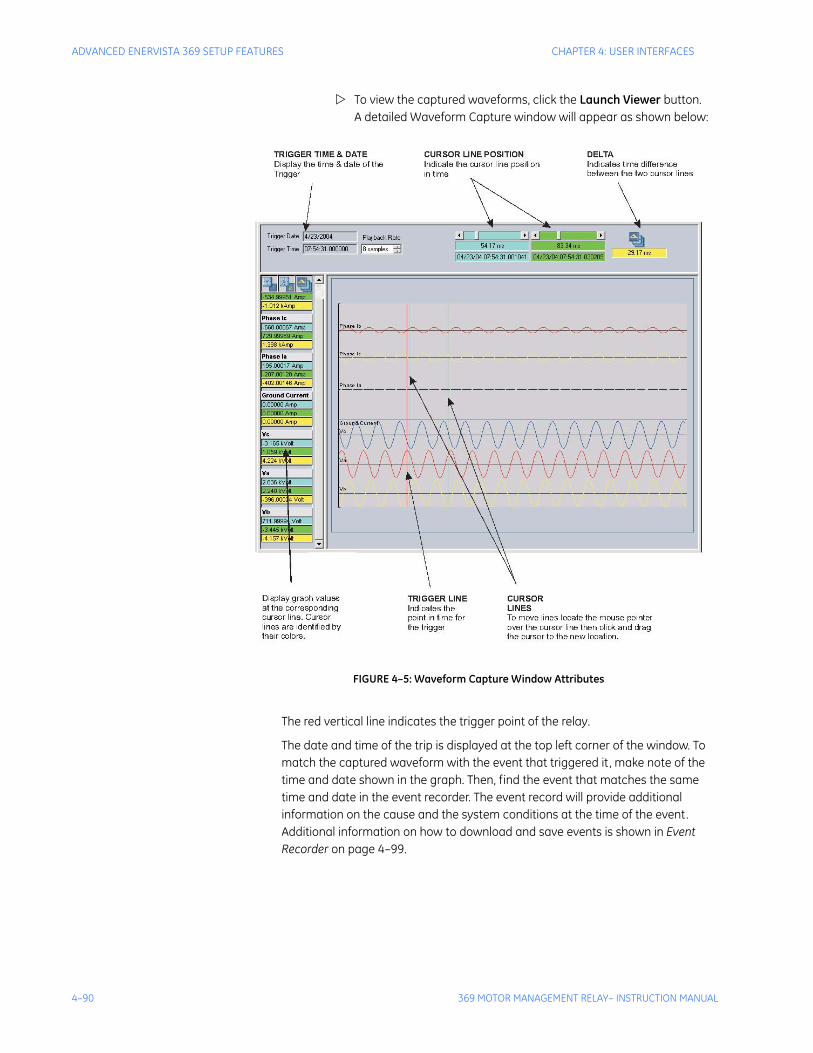
4–90 369 MOTOR MANAGEMENT RELAY– INSTRUCTION MANUAL
ADVANCED ENERVISTA 369 SETUP FEATURES CHAPTER 4: USER INTERFACES
To view the captured waveforms, click the Launch Viewer button. A detailed Waveform Capture window will appear as shown below:
FIGURE 4–5: Waveform Capture Window Attributes
The red vertical line indicates the trigger point of the relay.
The date and time of the trip is displayed at the top left corner of the window. To match the captured waveform with the event that triggered it , make note of the time and date shown in the graph. Then, find the event that matches the same time and date in the event recorder. The event record will provide additional information on the cause and the system conditions at the time of the event. Additional information on how to download and save events is shown in Event Recorder on page 4–99.

CHAPTER 4: USER INTERFACES ADVANCED ENERVISTA 369 SETUP FEATURES
369 MOTOR MANAGEMENT RELAY– INSTRUCTION MANUAL 4–91
4.6.4 Motor Start Data LoggerIn addition to the learned information captured for every start, the Motor Start Data Logger will record up to 30 seconds of digital and analog waveforms during motor starts. Captured information includes:
• Individual and average phase current
• Current unbalance
• Ground current
• Individual and average phase voltages
• Thermal capacity used
• System frequency
• Breaker status contact
• Motor speed (low/high)
4.6.5 Data LoggerThe user-configurable Data Logger allows users to trend information to help configure protection setpoints, as well as to schedule preventative maintenance. The Data Logger:
• allows trending of up to 16 analog or digital parameters at a time
• allows trending of any metered or calculated analog value within a provided list
• allows trending of digital input and output states
• stores all trended information in the relay’s volatile memory (RAM)
• allows user-configurable resolution of trending from 1 second to 1 hour (3600s)
• allows up to 50 Logs to be created
• is available only with the Enhanced “E” option.
4.6.5.1Support in Enervista PC Software
Enervista PC Program supports the Data Logger on two screens on the Online Device tree:
1. Setpoints: Settings > S1 Setup > Data Logger
2. Actual Values: Actual Values > A1 Motor Status > Data Logger
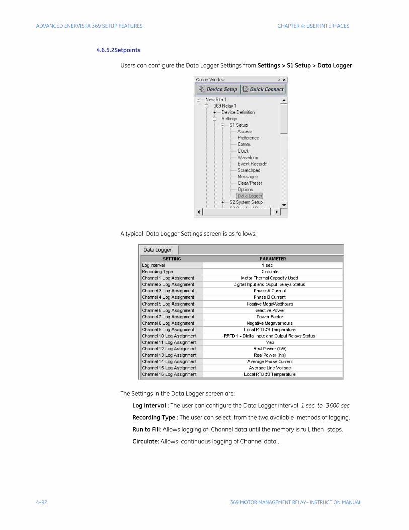
4–92 369 MOTOR MANAGEMENT RELAY– INSTRUCTION MANUAL
ADVANCED ENERVISTA 369 SETUP FEATURES CHAPTER 4: USER INTERFACES
4.6.5.2Setpoints
Users can configure the Data Logger Settings from Settings > S1 Setup > Data Logger
A typical Data Logger Settings screen is as follows:
The Settings in the Data Logger screen are:
Log Interval : The user can configure the Data Logger interval 1 sec to 3600 sec
Recording Type : The user can select from the two available methods of logging.
Run to Fill: Allows logging of Channel data until the memory is full, then stops.
Circulate: Allows continuous logging of Channel data .
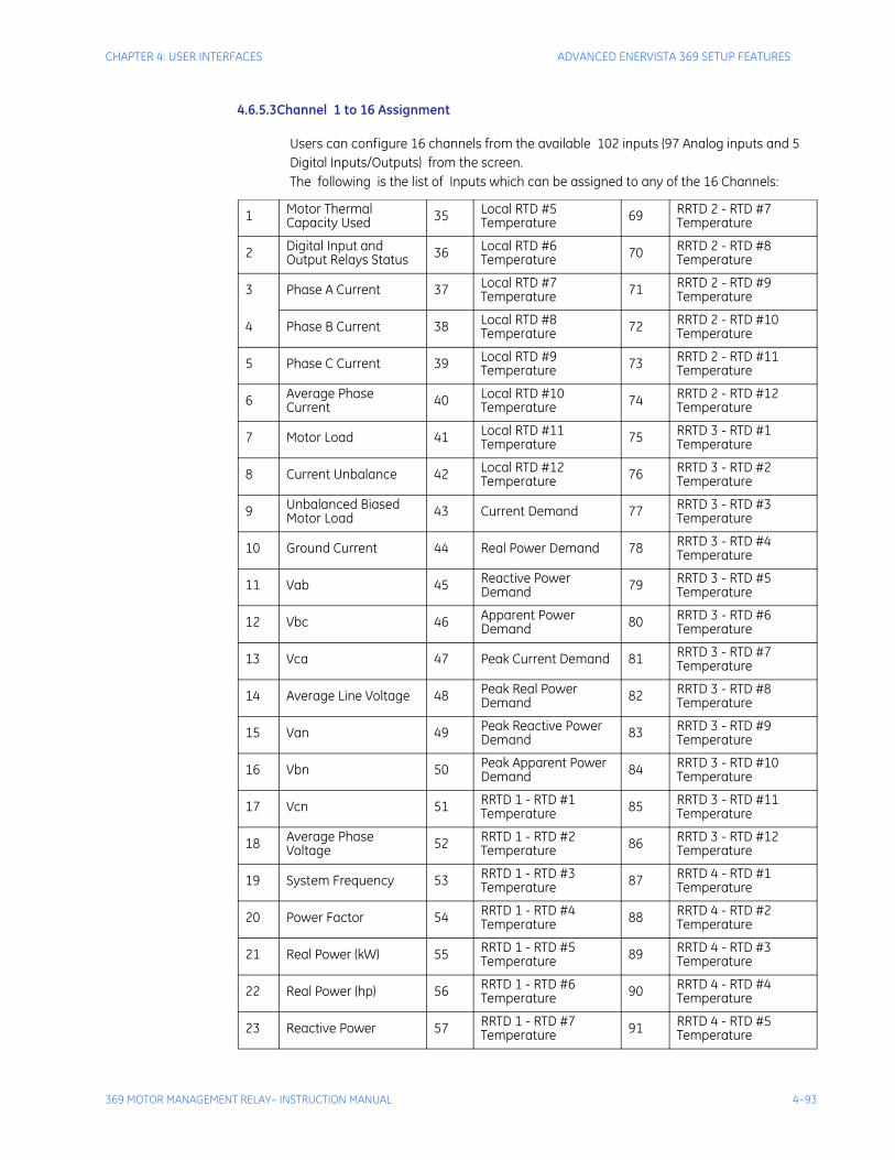
CHAPTER 4: USER INTERFACES ADVANCED ENERVISTA 369 SETUP FEATURES
369 MOTOR MANAGEMENT RELAY– INSTRUCTION MANUAL 4–93
4.6.5.3Channel 1 to 16 Assignment
Users can configure 16 channels from the available 102 inputs (97 Analog inputs and 5 Digital Inputs/Outputs) from the screen. The following is the list of Inputs which can be assigned to any of the 16 Channels:
1 Motor Thermal Capacity Used 35 Local RTD #5
Temperature 69 RRTD 2 - RTD #7 Temperature
2 Digital Input and Output Relays Status 36 Local RTD #6
Temperature 70 RRTD 2 - RTD #8 Temperature
3 Phase A Current 37 Local RTD #7 Temperature 71 RRTD 2 - RTD #9
Temperature
4 Phase B Current 38 Local RTD #8 Temperature 72 RRTD 2 - RTD #10
Temperature
5 Phase C Current 39 Local RTD #9 Temperature 73 RRTD 2 - RTD #11
Temperature
6 Average Phase Current 40 Local RTD #10
Temperature 74 RRTD 2 - RTD #12 Temperature
7 Motor Load 41 Local RTD #11 Temperature 75 RRTD 3 - RTD #1
Temperature
8 Current Unbalance 42 Local RTD #12 Temperature 76 RRTD 3 - RTD #2
Temperature
9 Unbalanced Biased Motor Load 43 Current Demand 77 RRTD 3 - RTD #3
Temperature
10 Ground Current 44 Real Power Demand 78 RRTD 3 - RTD #4 Temperature
11 Vab 45 Reactive Power Demand 79 RRTD 3 - RTD #5
Temperature
12 Vbc 46 Apparent Power Demand 80 RRTD 3 - RTD #6
Temperature
13 Vca 47 Peak Current Demand 81 RRTD 3 - RTD #7 Temperature
14 Average Line Voltage 48 Peak Real Power Demand 82 RRTD 3 - RTD #8
Temperature
15 Van 49 Peak Reactive Power Demand 83 RRTD 3 - RTD #9
Temperature
16 Vbn 50 Peak Apparent Power Demand 84 RRTD 3 - RTD #10
Temperature
17 Vcn 51 RRTD 1 - RTD #1 Temperature 85 RRTD 3 - RTD #11
Temperature
18 Average Phase Voltage 52 RRTD 1 - RTD #2
Temperature 86 RRTD 3 - RTD #12 Temperature
19 System Frequency 53 RRTD 1 - RTD #3 Temperature 87 RRTD 4 - RTD #1
Temperature
20 Power Factor 54 RRTD 1 - RTD #4 Temperature 88 RRTD 4 - RTD #2
Temperature
21 Real Power (kW) 55 RRTD 1 - RTD #5 Temperature 89 RRTD 4 - RTD #3
Temperature
22 Real Power (hp) 56 RRTD 1 - RTD #6 Temperature 90 RRTD 4 - RTD #4
Temperature
23 Reactive Power 57 RRTD 1 - RTD #7 Temperature 91 RRTD 4 - RTD #5
Temperature
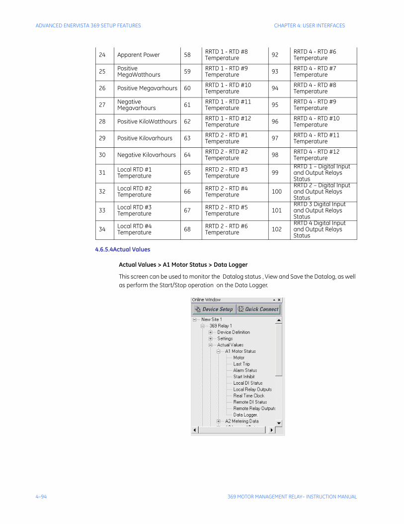
4–94 369 MOTOR MANAGEMENT RELAY– INSTRUCTION MANUAL
ADVANCED ENERVISTA 369 SETUP FEATURES CHAPTER 4: USER INTERFACES
4.6.5.4Actual Values
Actual Values > A1 Motor Status > Data Logger
This screen can be used to monitor the Datalog status , View and Save the Datalog, as well as perform the Start/Stop operation on the Data Logger.
24 Apparent Power 58 RRTD 1 - RTD #8 Temperature 92 RRTD 4 - RTD #6
Temperature
25 Positive MegaWatthours 59 RRTD 1 - RTD #9
Temperature 93 RRTD 4 - RTD #7 Temperature
26 Positive Megavarhours 60 RRTD 1 - RTD #10 Temperature 94 RRTD 4 - RTD #8
Temperature
27 Negative Megavarhours 61 RRTD 1 - RTD #11
Temperature 95 RRTD 4 - RTD #9 Temperature
28 Positive KiloWatthours 62 RRTD 1 - RTD #12 Temperature 96 RRTD 4 - RTD #10
Temperature
29 Positive Kilovarhours 63 RRTD 2 - RTD #1 Temperature 97 RRTD 4 - RTD #11
Temperature
30 Negative Kilovarhours 64 RRTD 2 - RTD #2 Temperature 98 RRTD 4 - RTD #12
Temperature
31 Local RTD #1 Temperature 65 RRTD 2 - RTD #3
Temperature 99RRTD 1 – Digital Input and Output Relays Status
32 Local RTD #2 Temperature 66 RRTD 2 - RTD #4
Temperature 100RRTD 2 – Digital Input and Output Relays Status
33 Local RTD #3 Temperature 67 RRTD 2 - RTD #5
Temperature 101RRTD 3 Digital Input and Output Relays Status
34 Local RTD #4 Temperature 68 RRTD 2 - RTD #6
Temperature 102RRTD 4 Digital Input and Output Relays Status
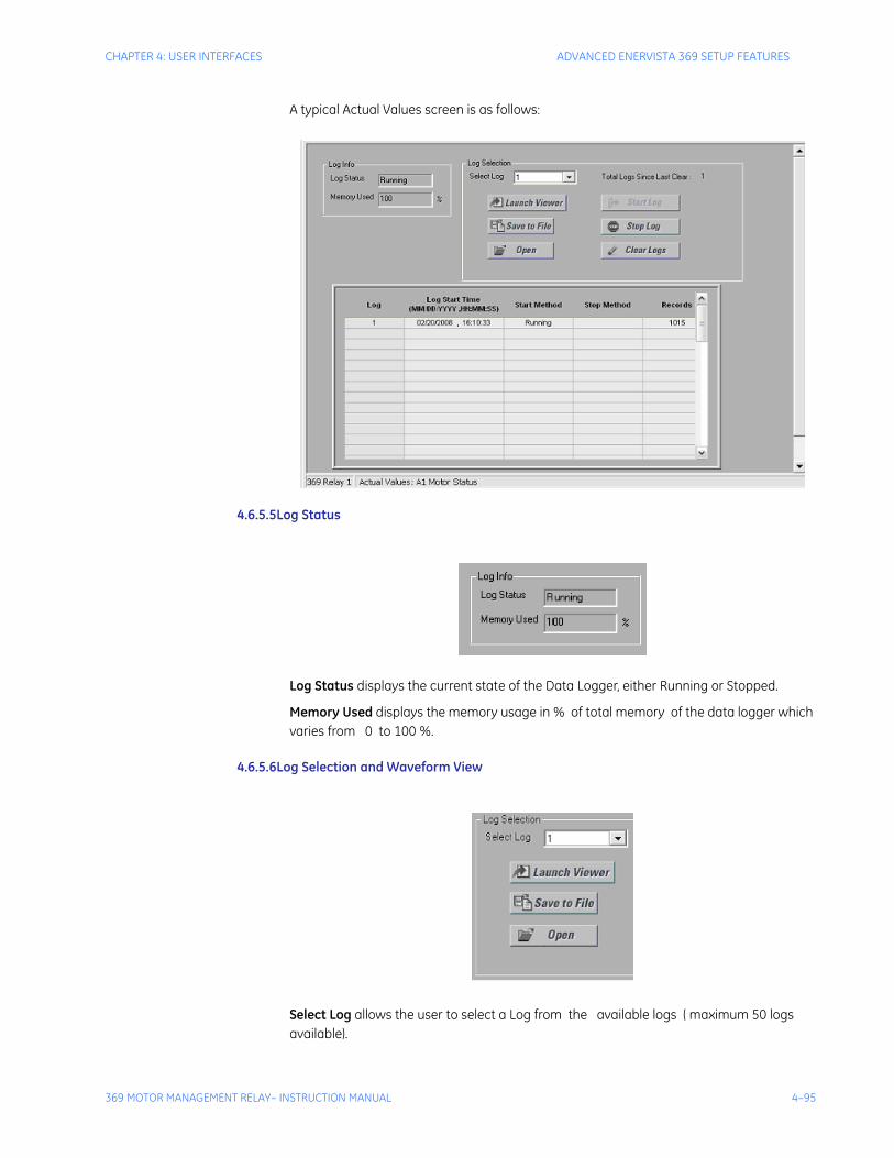
CHAPTER 4: USER INTERFACES ADVANCED ENERVISTA 369 SETUP FEATURES
369 MOTOR MANAGEMENT RELAY– INSTRUCTION MANUAL 4–95
A typical Actual Values screen is as follows:
4.6.5.5Log Status
Log Status displays the current state of the Data Logger, either Running or Stopped.
Memory Used displays the memory usage in % of total memory of the data logger which varies from 0 to 100 %.
4.6.5.6Log Selection and Waveform View
Select Log allows the user to select a Log from the available logs ( maximum 50 logs available).
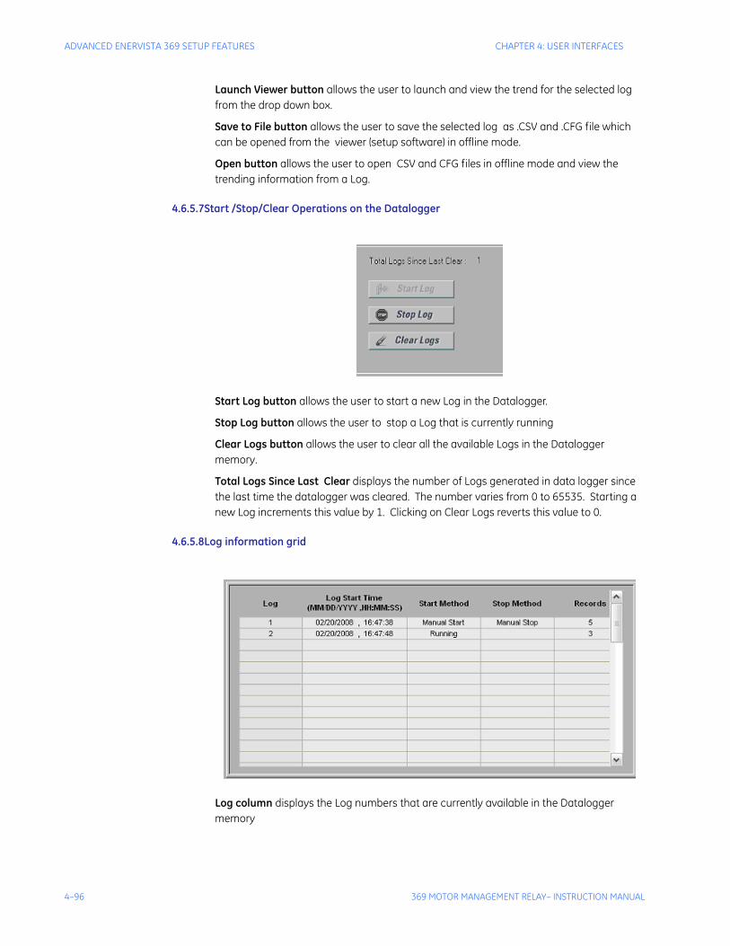
4–96 369 MOTOR MANAGEMENT RELAY– INSTRUCTION MANUAL
ADVANCED ENERVISTA 369 SETUP FEATURES CHAPTER 4: USER INTERFACES
Launch Viewer button allows the user to launch and view the trend for the selected log from the drop down box.
Save to File button allows the user to save the selected log as .CSV and .CFG file which can be opened from the viewer (setup software) in offline mode.
Open button allows the user to open CSV and CFG files in offline mode and view the trending information from a Log.
4.6.5.7Start /Stop/Clear Operations on the Datalogger
Start Log button allows the user to start a new Log in the Datalogger.
Stop Log button allows the user to stop a Log that is currently running
Clear Logs button allows the user to clear all the available Logs in the Datalogger memory.
Total Logs Since Last Clear displays the number of Logs generated in data logger since the last time the datalogger was cleared. The number varies from 0 to 65535. Starting a new Log increments this value by 1. Clicking on Clear Logs reverts this value to 0.
4.6.5.8Log information grid
Log column displays the Log numbers that are currently available in the Datalogger memory

CHAPTER 4: USER INTERFACES ADVANCED ENERVISTA 369 SETUP FEATURES
369 MOTOR MANAGEMENT RELAY– INSTRUCTION MANUAL 4–97
Log Start Time column displays the Date and Time (in MM/DD/YYYY, HH:MM:SS format) when the corresponding Log is generated
Start Method column displays the method by which the Log is started . This value can be either
• Manual Start - if the Log is generated by clicking the Start button
• Motor Start - if the Log is generated when the Motor is started from the OFF state.
Stop Method column displays the method by which the Log is stopped . This value can be either
• Manual Stop - if the Log is stopped by clicking the Stop button
• Motor Stop - if the Log is stopped when the motor is stopped from the Running state.
Records column displays the number of records stored in each Log.
4.6.5.9Grid Update
If the screen is kept open when the Data Log is running, information in the grid is automatically updated in the following cases:
• Start of a new Log (either manual start or motor start)
• Stopping the current Log (either manual stop or motor stop)
• Any of the existing Logs are erased when the log is running in Circulate mode
• Clearing the existing Logs.
Note If any of the above events do not occur, the data log screen will be updated automatically every 60 seconds.
4.6.6 Motor Health ReportThis reporting function is included with every 369 relay, providing critical information on the historical operating characteristics of your motor during motor starting and stopping operations. Included in the report are:
• Trip summary
• Motor operation historical timeline, displaying start, emergency restart, stop, trip, and alarm conditions
• Motor starting learned information (trending information over a maximum of 1250 motor start operations)
• Motor start data logger trends, including current, current unbalance, voltage, frequency, TCU, breaker contact status during start, and motor speed (low/high).
4.6.7 PhasorsThe EnerVista 369 Setup software can be used to view the phasor diagram of three-phase currents and voltages. The phasors are for: Phase Voltages Va, Vb, and Vc; Phase Currents Ia, Ib, and Ic.
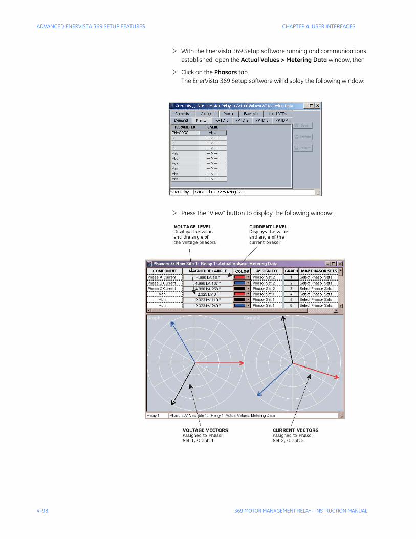
4–98 369 MOTOR MANAGEMENT RELAY– INSTRUCTION MANUAL
ADVANCED ENERVISTA 369 SETUP FEATURES CHAPTER 4: USER INTERFACES
With the EnerVista 369 Setup software running and communications established, open the Actual Values > Metering Data window, then
Click on the Phasors tab.The EnerVista 369 Setup software will display the following window:
Press the “View” button to display the following window:
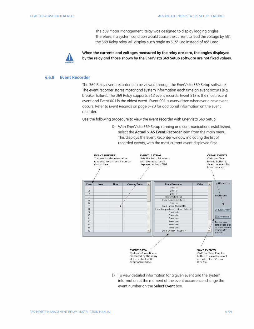
CHAPTER 4: USER INTERFACES ADVANCED ENERVISTA 369 SETUP FEATURES
369 MOTOR MANAGEMENT RELAY– INSTRUCTION MANUAL 4–99
The 369 Motor Management Relay was designed to display lagging angles. Therefore, if a system condition would cause the current to lead the voltage by 45°, the 369 Relay relay will display such angle as 315° Lag instead of 45° Lead.
When the currents and voltages measured by the relay are zero, the angles displayed by the relay and those shown by the EnerVista 369 Setup software are not fixed values.
4.6.8 Event RecorderThe 369 Relay event recorder can be viewed through the EnerVista 369 Setup software. The event recorder stores motor and system information each time an event occurs (e.g. breaker failure). The 369 Relay supports 512 event records. Event 512 is the most recent event and Event 001 is the oldest event. Event 001 is overwritten whenever a new event occurs. Refer to Event Records on page 6–20 for additional information on the event recorder.
Use the following procedure to view the event recorder with EnerVista 369 Setup:
With EnerVista 369 Setup running and communications established, select the Actual > A5 Event Recorder item from the main menu. This displays the Event Recorder window indicating the list of recorded events, with the most current event displayed first.
To view detailed information for a given event and the system information at the moment of the event occurrence, change the event number on the Select Event box.
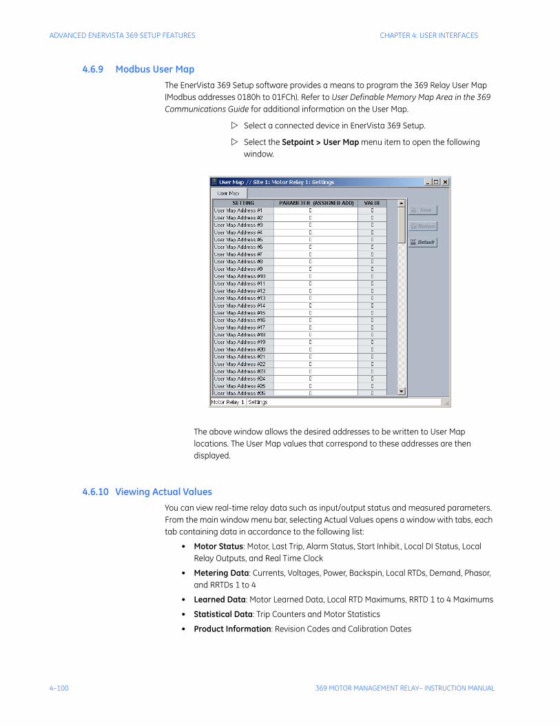
4–100 369 MOTOR MANAGEMENT RELAY– INSTRUCTION MANUAL
ADVANCED ENERVISTA 369 SETUP FEATURES CHAPTER 4: USER INTERFACES
4.6.9 Modbus User MapThe EnerVista 369 Setup software provides a means to program the 369 Relay User Map (Modbus addresses 0180h to 01FCh). Refer to User Definable Memory Map Area in the 369 Communications Guide for additional information on the User Map.
Select a connected device in EnerVista 369 Setup.
Select the Setpoint > User Map menu item to open the following window.
The above window allows the desired addresses to be written to User Map locations. The User Map values that correspond to these addresses are then displayed.
4.6.10 Viewing Actual ValuesYou can view real-time relay data such as input/output status and measured parameters. From the main window menu bar, selecting Actual Values opens a window with tabs, each tab containing data in accordance to the following list:
• Motor Status: Motor, Last Trip, Alarm Status, Start Inhibit, Local DI Status, Local Relay Outputs, and Real Time Clock
• Metering Data: Currents, Voltages, Power, Backspin, Local RTDs, Demand, Phasor, and RRTDs 1 to 4
• Learned Data: Motor Learned Data, Local RTD Maximums, RRTD 1 to 4 Maximums
• Statistical Data: Trip Counters and Motor Statistics
• Product Information: Revision Codes and Calibration Dates

CHAPTER 4: USER INTERFACES ADVANCED ENERVISTA 369 SETUP FEATURES
369 MOTOR MANAGEMENT RELAY– INSTRUCTION MANUAL 4–101
Selecting an actual values window also opens the actual values tree from the corresponding device in the site list and highlights the current location in the hierarchy.
For complete details on actual values, refer to Chapter 6.
To view a separate window for each group of actual values, select the desired item from the tree.
Double click with the left mouse button. Each group will be opened on a separate tab. The windows can be rearranged to maximize data viewing as shown in the following figure (showing actual current, voltage, and power values tiled in the same window):
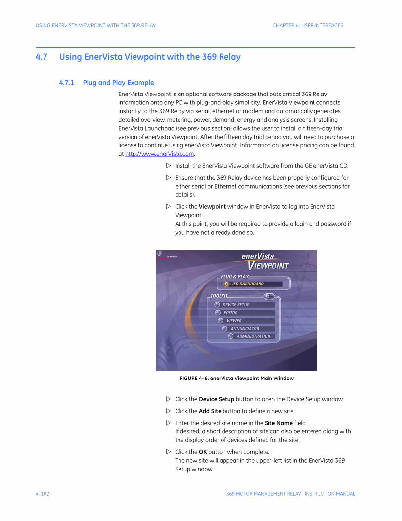
4–102 369 MOTOR MANAGEMENT RELAY– INSTRUCTION MANUAL
USING ENERVISTA VIEWPOINT WITH THE 369 RELAY CHAPTER 4: USER INTERFACES
4.7 Using EnerVista Viewpoint with the 369 Relay
4.7.1 Plug and Play ExampleEnerVista Viewpoint is an optional software package that puts critical 369 Relay information onto any PC with plug-and-play simplicity. EnerVista Viewpoint connects instantly to the 369 Relay via serial, ethernet or modem and automatically generates detailed overview, metering, power, demand, energy and analysis screens. Installing EnerVista Launchpad (see previous section) allows the user to install a fifteen-day trial version of enerVista Viewpoint. After the fifteen day trial period you will need to purchase a license to continue using enerVista Viewpoint. Information on license pricing can be found at http://www.enerVista.com.
Install the EnerVista Viewpoint software from the GE enerVista CD.
Ensure that the 369 Relay device has been properly configured for either serial or Ethernet communications (see previous sections for details).
Click the Viewpoint window in EnerVista to log into EnerVista Viewpoint. At this point, you will be required to provide a login and password if you have not already done so.
FIGURE 4–6: enerVista Viewpoint Main Window
Click the Device Setup button to open the Device Setup window.
Click the Add Site button to define a new site.
Enter the desired site name in the Site Name field. If desired, a short description of site can also be entered along with the display order of devices defined for the site.
Click the OK button when complete. The new site will appear in the upper-left list in the EnerVista 369 Setup window.
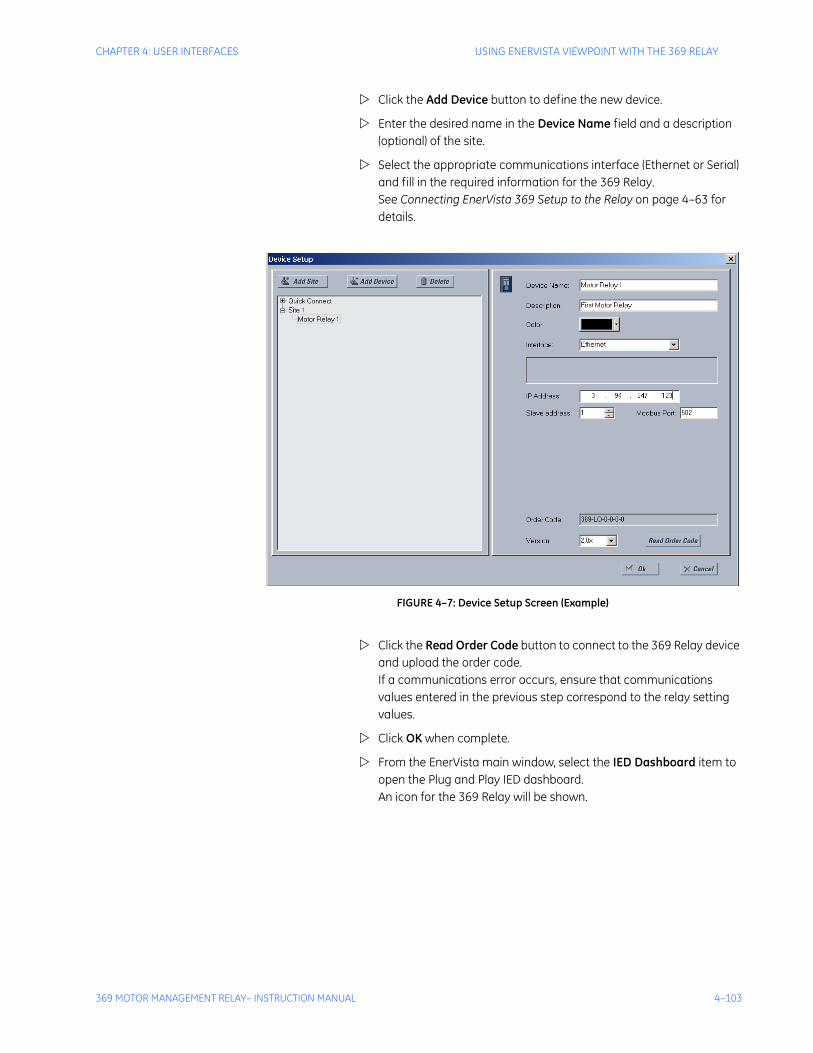
CHAPTER 4: USER INTERFACES USING ENERVISTA VIEWPOINT WITH THE 369 RELAY
369 MOTOR MANAGEMENT RELAY– INSTRUCTION MANUAL 4–103
Click the Add Device button to define the new device.
Enter the desired name in the Device Name field and a description (optional) of the site.
Select the appropriate communications interface (Ethernet or Serial) and fill in the required information for the 369 Relay. See Connecting EnerVista 369 Setup to the Relay on page 4–63 for details.
FIGURE 4–7: Device Setup Screen (Example)
Click the Read Order Code button to connect to the 369 Relay device and upload the order code. If a communications error occurs, ensure that communications values entered in the previous step correspond to the relay setting values.
Click OK when complete.
From the EnerVista main window, select the IED Dashboard item to open the Plug and Play IED dashboard. An icon for the 369 Relay will be shown.
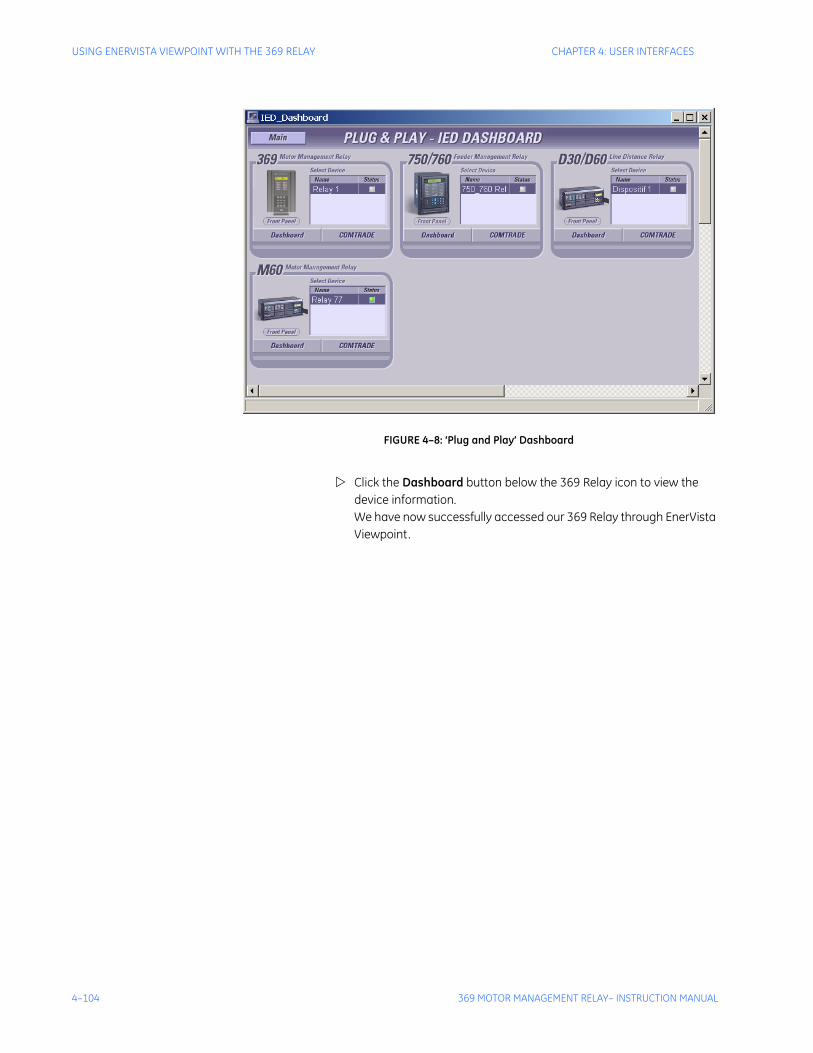
4–104 369 MOTOR MANAGEMENT RELAY– INSTRUCTION MANUAL
USING ENERVISTA VIEWPOINT WITH THE 369 RELAY CHAPTER 4: USER INTERFACES
FIGURE 4–8: ‘Plug and Play’ Dashboard
Click the Dashboard button below the 369 Relay icon to view the device information. We have now successfully accessed our 369 Relay through EnerVista Viewpoint.
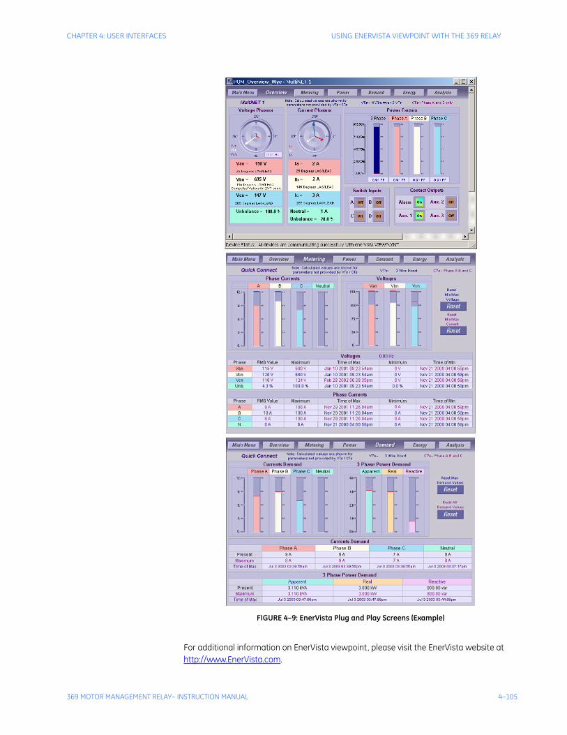
CHAPTER 4: USER INTERFACES USING ENERVISTA VIEWPOINT WITH THE 369 RELAY
369 MOTOR MANAGEMENT RELAY– INSTRUCTION MANUAL 4–105
FIGURE 4–9: EnerVista Plug and Play Screens (Example)
For additional information on EnerVista viewpoint, please visit the EnerVista website at http://www.EnerVista.com.

4–106 369 MOTOR MANAGEMENT RELAY– INSTRUCTION MANUAL
USING ENERVISTA VIEWPOINT WITH THE 369 RELAY CHAPTER 4: USER INTERFACES
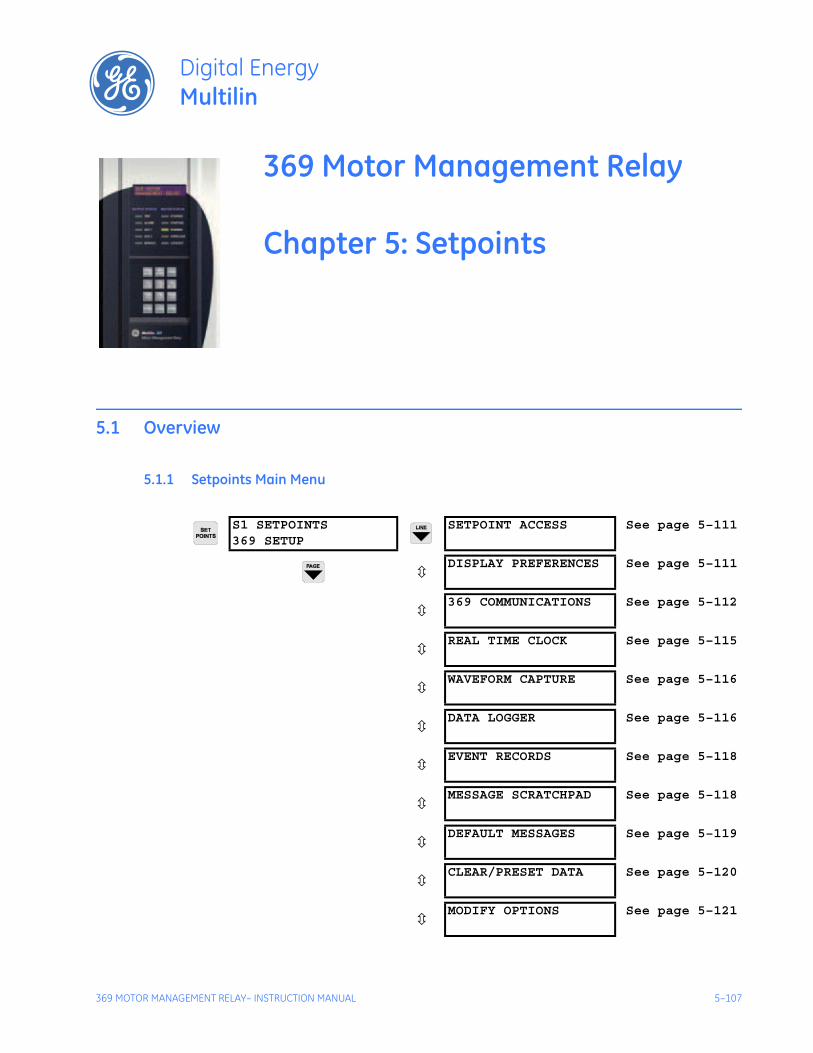
369 MOTOR MANAGEMENT RELAY– INSTRUCTION MANUAL 5–107
369 Motor Management Relay
Chapter 5: Setpoints
Digital EnergyMultilin
Setpoints
5.1 Overview
5.1.1 Setpoints Main Menu
S1 SETPOINTS369 SETUP
SETPOINT ACCESS See page 5–111
DISPLAY PREFERENCES See page 5–111
369 COMMUNICATIONS See page 5–112
REAL TIME CLOCK See page 5–115
WAVEFORM CAPTURE See page 5–116
DATA LOGGER See page 5–116
EVENT RECORDS See page 5–118
MESSAGE SCRATCHPAD See page 5–118
DEFAULT MESSAGES See page 5–119
CLEAR/PRESET DATA See page 5–120
MODIFY OPTIONS See page 5–121
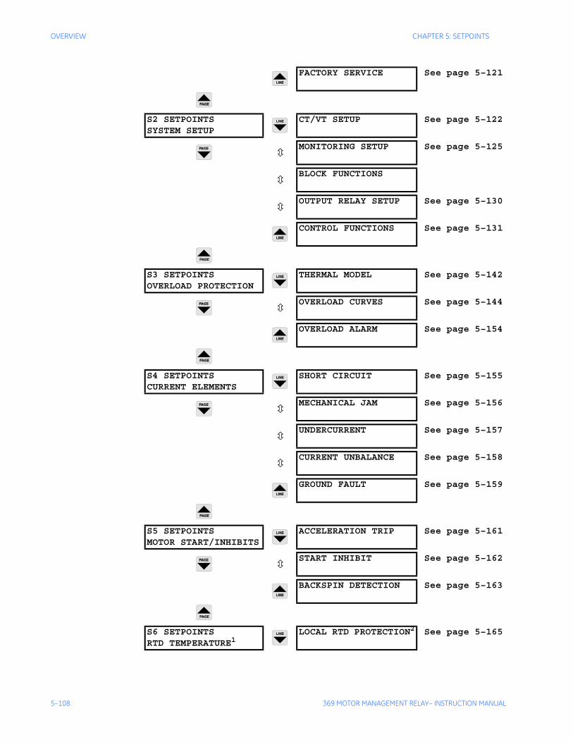
5–108 369 MOTOR MANAGEMENT RELAY– INSTRUCTION MANUAL
OVERVIEW CHAPTER 5: SETPOINTS
FACTORY SERVICE See page 5–121
S2 SETPOINTSSYSTEM SETUP
CT/VT SETUP See page 5–122
MONITORING SETUP See page 5–125
BLOCK FUNCTIONS
OUTPUT RELAY SETUP See page 5–130
CONTROL FUNCTIONS See page 5–131
S3 SETPOINTSOVERLOAD PROTECTION
THERMAL MODEL See page 5–142
OVERLOAD CURVES See page 5–144
OVERLOAD ALARM See page 5–154
S4 SETPOINTSCURRENT ELEMENTS
SHORT CIRCUIT See page 5–155
MECHANICAL JAM See page 5–156
UNDERCURRENT See page 5–157
CURRENT UNBALANCE See page 5–158
GROUND FAULT See page 5–159
S5 SETPOINTSMOTOR START/INHIBITS
ACCELERATION TRIP See page 5–161
START INHIBIT See page 5–162
BACKSPIN DETECTION See page 5–163
S6 SETPOINTSRTD TEMPERATURE1
LOCAL RTD PROTECTION2 See page 5–165
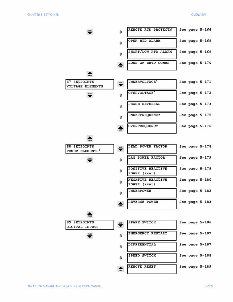
CHAPTER 5: SETPOINTS OVERVIEW
369 MOTOR MANAGEMENT RELAY– INSTRUCTION MANUAL 5–109
REMOTE RTD PROTECTN3 See page 5–166
OPEN RTD ALARM See page 5–169
SHORT/LOW RTD ALARM See page 5–169
LOSS OF RRTD COMMS See page 5–170
S7 SETPOINTSVOLTAGE ELEMENTS
UNDERVOLTAGE4 See page 5–171
OVERVOLTAGE4 See page 5–172
PHASE REVERSAL See page 5–173
UNDERFREQUENCY See page 5–175
OVERFREQUENCY See page 5–176
S8 SETPOINTSPOWER ELEMENTS4
LEAD POWER FACTOR See page 5–178
LAG POWER FACTOR See page 5–179
POSITIVE REACTIVEPOWER (kvar)
See page 5–179
NEGATIVE REACTIVEPOWER (kvar)
See page 5–180
UNDERPOWER See page 5–182
REVERSE POWER See page 5–183
S9 SETPOINTSDIGITAL INPUTS
SPARE SWITCH See page 5–186
EMERGENCY RESTART See page 5–187
DIFFERENTIAL See page 5–187
SPEED SWITCH See page 5–188
REMOTE RESET See page 5–189
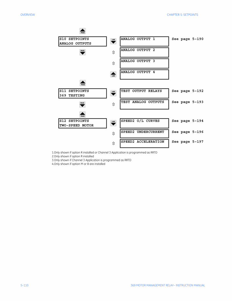
5–110 369 MOTOR MANAGEMENT RELAY– INSTRUCTION MANUAL
OVERVIEW CHAPTER 5: SETPOINTS
S10 SETPOINTSANALOG OUTPUTS
ANALOG OUTPUT 1 See page 5–190
ANALOG OUTPUT 2
ANALOG OUTPUT 3
ANALOG OUTPUT 4
S11 SETPOINTS369 TESTING
TEST OUTPUT RELAYS See page 5–192
TEST ANALOG OUTPUTS See page 5–193
S12 SETPOINTSTWO-SPEED MOTOR
SPEED2 O/L CURVES See page 5–194
SPEED2 UNDERCURRENT See page 5–196
SPEED2 ACCELERATION See page 5–197
1.Only shown if option R installed or Channel 3 Application is programmed as RRTD2.Only shown if option R installed3.Only shown if Channel 3 Application is programmed as RRTD4.Only shown if option M or B are installed
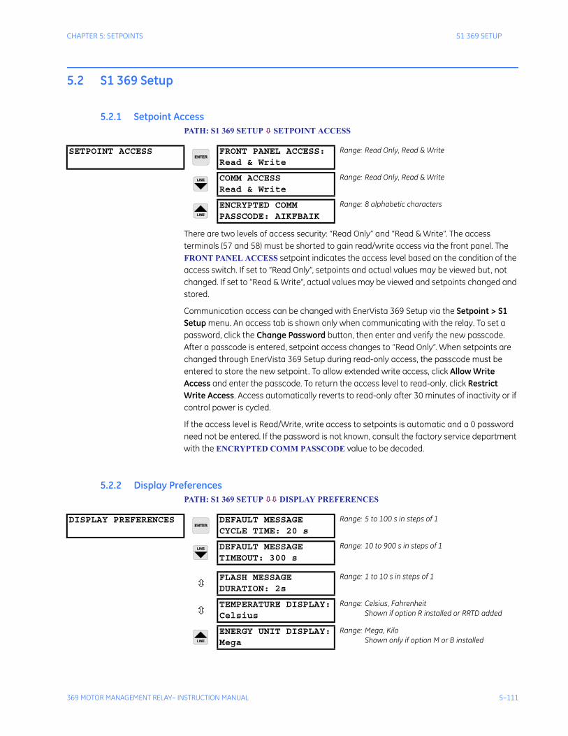
CHAPTER 5: SETPOINTS S1 369 SETUP
369 MOTOR MANAGEMENT RELAY– INSTRUCTION MANUAL 5–111
5.2 S1 369 Setup
5.2.1 Setpoint AccessPATH: S1 369 SETUP SETPOINT ACCESS
There are two levels of access security: “Read Only” and “Read & Write”. The access terminals (57 and 58) must be shorted to gain read/write access via the front panel. The FRONT PANEL ACCESS setpoint indicates the access level based on the condition of the access switch. If set to “Read Only”, setpoints and actual values may be viewed but, not changed. If set to “Read & Write”, actual values may be viewed and setpoints changed and stored.
Communication access can be changed with EnerVista 369 Setup via the Setpoint > S1 Setup menu. An access tab is shown only when communicating with the relay. To set a password, click the Change Password button, then enter and verify the new passcode. After a passcode is entered, setpoint access changes to “Read Only”. When setpoints are changed through EnerVista 369 Setup during read-only access, the passcode must be entered to store the new setpoint. To allow extended write access, click Allow Write Access and enter the passcode. To return the access level to read-only, click Restrict Write Access. Access automatically reverts to read-only after 30 minutes of inactivity or if control power is cycled.
If the access level is Read/Write, write access to setpoints is automatic and a 0 password need not be entered. If the password is not known, consult the factory service department with the ENCRYPTED COMM PASSCODE value to be decoded.
5.2.2 Display PreferencesPATH: S1 369 SETUP DISPLAY PREFERENCES
SETPOINT ACCESS FRONT PANEL ACCESS:Read & Write
Range: Read Only, Read & Write
COMM ACCESSRead & Write
Range: Read Only, Read & Write
ENCRYPTED COMMPASSCODE: AIKFBAIK
Range: 8 alphabetic characters
DISPLAY PREFERENCES DEFAULT MESSAGECYCLE TIME: 20 s
Range: 5 to 100 s in steps of 1
DEFAULT MESSAGETIMEOUT: 300 s
Range: 10 to 900 s in steps of 1
FLASH MESSAGEDURATION: 2s
Range: 1 to 10 s in steps of 1
TEMPERATURE DISPLAY:Celsius
Range: Celsius, FahrenheitShown if option R installed or RRTD added
ENERGY UNIT DISPLAY:Mega
Range: Mega, KiloShown only if option M or B installed
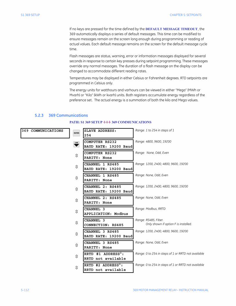
5–112 369 MOTOR MANAGEMENT RELAY– INSTRUCTION MANUAL
S1 369 SETUP CHAPTER 5: SETPOINTS
If no keys are pressed for the time defined by the DEFAULT MESSAGE TIMEOUT , the 369 automatically displays a series of default messages. This time can be modified to ensure messages remain on the screen long enough during programming or reading of actual values. Each default message remains on the screen for the default message cycle time.
Flash messages are status, warning, error or information messages displayed for several seconds in response to certain key presses during setpoint programming. These messages override any normal messages. The duration of a flash message on the display can be changed to accommodate different reading rates.
Temperatures may be displayed in either Celsius or Fahrenheit degrees. RTD setpoints are programmed in Celsius only.
The energy units for watthours and varhours can be viewed in either “Mega” (MWh or Mvarh) or “Kilo” (kWh or kvarh) units. Both registers accumulate energy regardless of the preference set. The actual energy is a summation of both the kilo and Mega values.
5.2.3 369 CommunicationsPATH: S1 369 SETUP 369 COMMUNICATIONS
369 COMMUNICATIONS SLAVE ADDRESS:254
Range: 1 to 254 in steps of 1
COMPUTER RS232BAUD RATE: 19200 Baud
Range: 4800, 9600, 19200
COMPUTER RS232PARITY: None
Range: None, Odd, Even
CHANNEL 1 RS485BAUD RATE: 19200 Baud
Range: 1200, 2400, 4800, 9600, 19200
CHANNEL 1 RS485PARITY: None
Range: None, Odd, Even
CHANNEL 2: RS485BAUD RATE: 19200 Baud
Range: 1200, 2400, 4800, 9600, 19200
CHANNEL 2: RS485PARITY: None
Range: None, Odd, Even
CHANNEL 3APPLICATION: Modbus
Range: Modbus, RRTD
CHANNEL 3CONNECTION: RS485
Range: RS485, Fiber.Only shown if option F is installed.
CHANNEL 3 RS485BAUD RATE: 19200 Baud
Range: 1200, 2400, 4800, 9600, 19200
CHANNEL 3 RS485PARITY: None
Range: None, Odd, Even
RRTD #1 ADDRESS1:RRTD not available
Range: 0 to 254 in steps of 1 or RRTD not available
RRTD #2 ADDRESS1:RRTD not available
Range: 0 to 254 in steps of 1 or RRTD not available
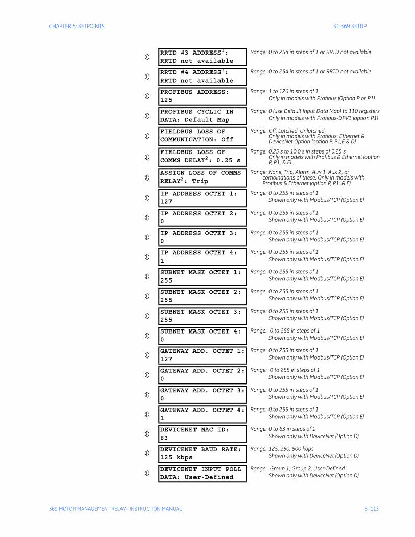
CHAPTER 5: SETPOINTS S1 369 SETUP
369 MOTOR MANAGEMENT RELAY– INSTRUCTION MANUAL 5–113
RRTD #3 ADDRESS1:RRTD not available
Range: 0 to 254 in steps of 1 or RRTD not available
RRTD #4 ADDRESS1:RRTD not available
Range: 0 to 254 in steps of 1 or RRTD not available
PROFIBUS ADDRESS:125
Range: 1 to 126 in steps of 1Only in models with Profibus (Option P or P1)
PROFIBUS CYCLIC INDATA: Default Map
Range: 0 (use Default Input Data Map) to 110 registersOnly in models with Profibus-DPV1 (option P1)
FIELDBUS LOSS OFCOMMUNICATION: Off
Range: Off, Latched, UnlatchedOnly in models with Profibus, Ethernet & DeviceNet Option (option P, P1,E & D)
FIELDBUS LOSS OF COMMS DELAY2: 0.25 s
Range: 0.25 s to 10.0 s in steps of 0.25 sOnly in models with Profibus & Ethernet (option P, P1, & E).
ASSIGN LOSS OF COMMS RELAY2: Trip
Range: None, Trip, Alarm, Aux 1, Aux 2, or combinations of these. Only in models with Profibus & Ethernet (option P, P1, & E).
IP ADDRESS OCTET 1:127
Range: 0 to 255 in steps of 1Shown only with Modbus/TCP (Option E)
IP ADDRESS OCTET 2:0
Range: 0 to 255 in steps of 1Shown only with Modbus/TCP (Option E)
IP ADDRESS OCTET 3:0
Range: 0 to 255 in steps of 1Shown only with Modbus/TCP (Option E)
IP ADDRESS OCTET 4:1
Range: 0 to 255 in steps of 1Shown only with Modbus/TCP (Option E)
SUBNET MASK OCTET 1:255
Range: 0 to 255 in steps of 1Shown only with Modbus/TCP (Option E)
SUBNET MASK OCTET 2:255
Range: 0 to 255 in steps of 1Shown only with Modbus/TCP (Option E)
SUBNET MASK OCTET 3:255
Range: 0 to 255 in steps of 1Shown only with Modbus/TCP (Option E)
SUBNET MASK OCTET 4:0
Range: 0 to 255 in steps of 1Shown only with Modbus/TCP (Option E)
GATEWAY ADD. OCTET 1:127
Range: 0 to 255 in steps of 1Shown only with Modbus/TCP (Option E)
GATEWAY ADD. OCTET 2:0
Range: 0 to 255 in steps of 1Shown only with Modbus/TCP (Option E)
GATEWAY ADD. OCTET 3:0
Range: 0 to 255 in steps of 1Shown only with Modbus/TCP (Option E)
GATEWAY ADD. OCTET 4:1
Range: 0 to 255 in steps of 1Shown only with Modbus/TCP (Option E)
DEVICENET MAC ID:63
Range: 0 to 63 in steps of 1Shown only with DeviceNet (Option D)
DEVICENET BAUD RATE:125 kbps
Range: 125, 250, 500 kbpsShown only with DeviceNet (Option D)
DEVICENET INPUT POLLDATA: User-Defined
Range: Group 1, Group 2, User-DefinedShown only with DeviceNet (Option D)
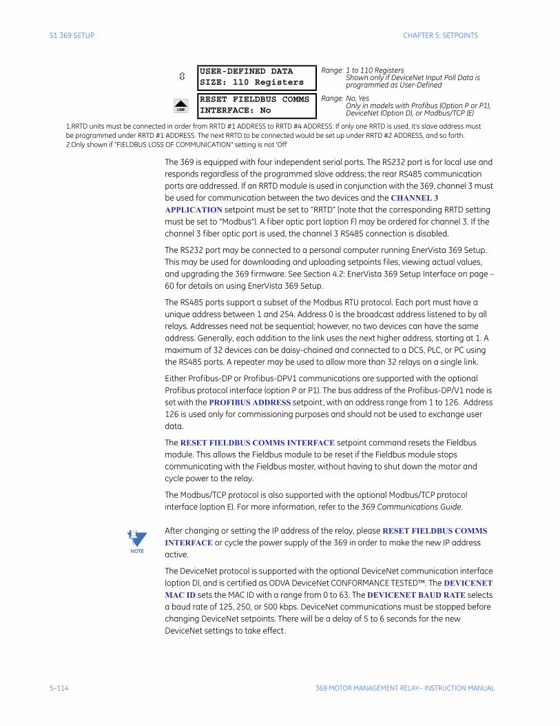
5–114 369 MOTOR MANAGEMENT RELAY– INSTRUCTION MANUAL
S1 369 SETUP CHAPTER 5: SETPOINTS
The 369 is equipped with four independent serial ports. The RS232 port is for local use and responds regardless of the programmed slave address; the rear RS485 communication ports are addressed. If an RRTD module is used in conjunction with the 369, channel 3 must be used for communication between the two devices and the CHANNEL 3 APPLICATION setpoint must be set to “RRTD” (note that the corresponding RRTD setting must be set to “Modbus”). A fiber optic port (option F) may be ordered for channel 3. If the channel 3 fiber optic port is used, the channel 3 RS485 connection is disabled.
The RS232 port may be connected to a personal computer running EnerVista 369 Setup. This may be used for downloading and uploading setpoints files, viewing actual values, and upgrading the 369 firmware. See Section 4.2: EnerVista 369 Setup Interface on page –60 for details on using EnerVista 369 Setup.
The RS485 ports support a subset of the Modbus RTU protocol. Each port must have a unique address between 1 and 254. Address 0 is the broadcast address listened to by all relays. Addresses need not be sequential; however, no two devices can have the same address. Generally, each addition to the link uses the next higher address, starting at 1. A maximum of 32 devices can be daisy-chained and connected to a DCS, PLC, or PC using the RS485 ports. A repeater may be used to allow more than 32 relays on a single link.
Either Profibus-DP or Profibus-DPV1 communications are supported with the optional Profibus protocol interface (option P or P1). The bus address of the Profibus-DP/V1 node is set with the PROFIBUS ADDRESS setpoint, with an address range from 1 to 126. Address 126 is used only for commissioning purposes and should not be used to exchange user data.
The RESET FIELDBUS COMMS INTERFACE setpoint command resets the Fieldbus module. This allows the Fieldbus module to be reset if the Fieldbus module stops communicating with the Fieldbus master, without having to shut down the motor and cycle power to the relay.
The Modbus/TCP protocol is also supported with the optional Modbus/TCP protocol interface (option E). For more information, refer to the 369 Communications Guide.
Note After changing or setting the IP address of the relay, please RESET FIELDBUS COMMS INTERFACE or cycle the power supply of the 369 in order to make the new IP address active.
The DeviceNet protocol is supported with the optional DeviceNet communication interface (option D), and is certified as ODVA DeviceNet CONFORMANCE TESTED™. The DEVICENET MAC ID sets the MAC ID with a range from 0 to 63. The DEVICENET BAUD RATE selects a baud rate of 125, 250, or 500 kbps. DeviceNet communications must be stopped before changing DeviceNet setpoints. There will be a delay of 5 to 6 seconds for the new DeviceNet settings to take effect.
USER-DEFINED DATASIZE: 110 Registers
Range: 1 to 110 RegistersShown only if DeviceNet Input Poll Data is programmed as User-Defined
RESET FIELDBUS COMMSINTERFACE: No
Range: No, YesOnly in models with Profibus (Option P or P1), DeviceNet (Option D), or Modbus/TCP (E)
1.RRTD units must be connected in order from RRTD #1 ADDRESS to RRTD #4 ADDRESS. If only one RRTD is used, it's slave address mustbe programmed under RRTD #1 ADDRESS. The next RRTD to be connected would be set up under RRTD #2 ADDRESS, and so forth. 2.Only shown if "FIELDBUS LOSS OF COMMUNICATION" setting is not 'Off'
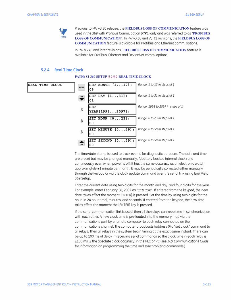
CHAPTER 5: SETPOINTS S1 369 SETUP
369 MOTOR MANAGEMENT RELAY– INSTRUCTION MANUAL 5–115
Note Previous to FW v3.30 release, the FIELDBUS LOSS OF COMMUNICATION feature was used in the 369 with Profibus Comm. option (P/P1) only and was referred to as “PROFIBUS LOSS OF COMMUNICATION”. In FW v3.30 and V3.31 revisions, the FIELDBUS LOSS OF COMMUNICATION feature is available for Profibus and Ethernet comm. options.
In FW v3.40 and later revisions, FIELDBUS LOSS OF COMMUNICATION feature is available for Profibus, Ethernet and DeviceNet comm. options.
5.2.4 Real Time ClockPATH: S1 369 SETUP REAL TIME CLOCK
The time/date stamp is used to track events for diagnostic purposes. The date and time are preset but may be changed manually. A battery backed internal clock runs continuously even when power is off. It has the same accuracy as an electronic watch approximately ±1 minute per month. It may be periodically corrected either manually through the keypad or via the clock update command over the serial link using EnerVista 369 Setup.
Enter the current date using two digits for the month and day, and four digits for the year. For example, enter February 28, 2007 as “02 28 2007". If entered from the keypad, the new date takes effect the moment [ENTER] is pressed. Set the time by using two digits for the hour (in 24 hour time), minutes, and seconds. If entered from the keypad, the new time takes effect the moment the [ENTER] key is pressed.
If the serial communication link is used, then all the relays can keep time in synchronization with each other. A new clock time is pre-loaded into the memory map via the communications port by a remote computer to each relay connected on the communications channel. The computer broadcasts (address 0) a “set clock” command to all relays. Then all relays in the system begin timing at the exact same instant. There can be up to 100 ms of delay in receiving serial commands so the clock time in each relay is ±100 ms, ± the absolute clock accuracy, in the PLC or PC (see 369 Communications Guide for information on programming the time and synchronizing commands.)
REAL TIME CLOCK SET MONTH [1...12]:09
Range: 1 to 12 in steps of 1
SET DAY [1...31]:01
Range: 1 to 31 in steps of 1
SET YEAR[1998...2097]:
Range: 1998 to 2097 in steps of 1
SET HOUR [0...23]:00
Range: 0 to 23 in steps of 1
SET MINUTE [0...59]:00
Range: 0 to 59 in steps of 1
SET SECOND [0...59]:00
Range: 0 to 59 in steps of 1
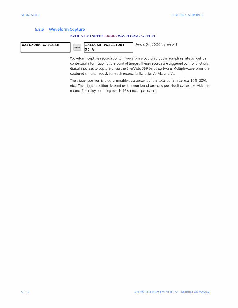
5–116 369 MOTOR MANAGEMENT RELAY– INSTRUCTION MANUAL
S1 369 SETUP CHAPTER 5: SETPOINTS
5.2.5 Waveform CapturePATH: S1 369 SETUP WAVEFORM CAPTURE
Waveform capture records contain waveforms captured at the sampling rate as well as contextual information at the point of trigger. These records are triggered by trip functions, digital input set to capture or via the EnerVista 369 Setup software. Multiple waveforms are captured simultaneously for each record: Ia, Ib, Ic, Ig, Va, Vb, and Vc.
The trigger position is programmable as a percent of the total buffer size (e.g. 10%, 50%, etc.). The trigger position determines the number of pre- and post-fault cycles to divide the record. The relay sampling rate is 16 samples per cycle.
WAVEFORM CAPTURE TRIGGER POSITION:50 %
Range: 0 to 100% in steps of 1
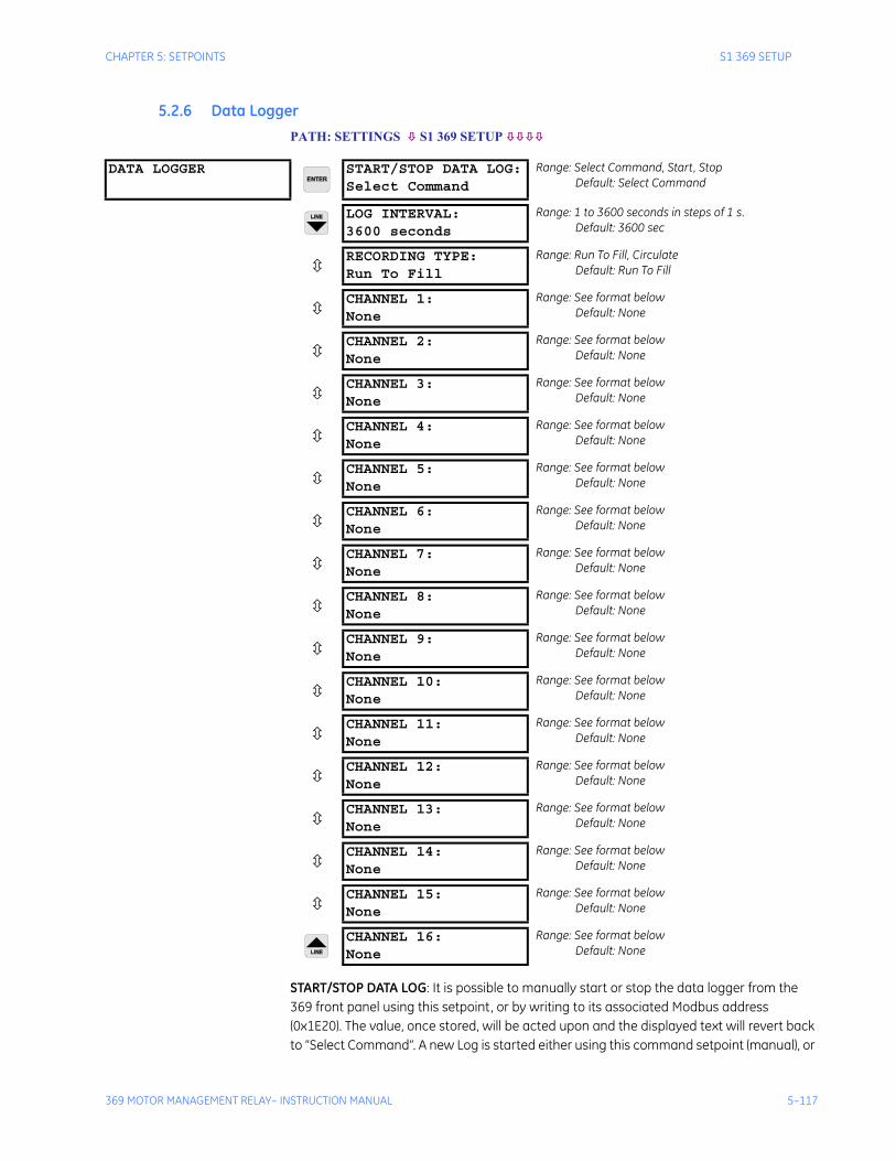
CHAPTER 5: SETPOINTS S1 369 SETUP
369 MOTOR MANAGEMENT RELAY– INSTRUCTION MANUAL 5–117
5.2.6 Data LoggerPATH: SETTINGS S1 369 SETUP
START/STOP DATA LOG: It is possible to manually start or stop the data logger from the 369 front panel using this setpoint, or by writing to its associated Modbus address (0x1E20). The value, once stored, will be acted upon and the displayed text will revert back to “Select Command”. A new Log is started either using this command setpoint (manual), or
DATA LOGGER START/STOP DATA LOG:Select Command
Range: Select Command, Start, StopDefault: Select Command
LOG INTERVAL:3600 seconds
Range: 1 to 3600 seconds in steps of 1 s. Default: 3600 sec
RECORDING TYPE:Run To Fill
Range: Run To Fill, CirculateDefault: Run To Fill
CHANNEL 1:None
Range: See format belowDefault: None
CHANNEL 2:None
Range: See format belowDefault: None
CHANNEL 3:None
Range: See format belowDefault: None
CHANNEL 4:None
Range: See format belowDefault: None
CHANNEL 5:None
Range: See format belowDefault: None
CHANNEL 6:None
Range: See format belowDefault: None
CHANNEL 7:None
Range: See format belowDefault: None
CHANNEL 8:None
Range: See format belowDefault: None
CHANNEL 9:None
Range: See format belowDefault: None
CHANNEL 10:None
Range: See format belowDefault: None
CHANNEL 11:None
Range: See format belowDefault: None
CHANNEL 12:None
Range: See format belowDefault: None
CHANNEL 13:None
Range: See format belowDefault: None
CHANNEL 14:None
Range: See format belowDefault: None
CHANNEL 15:None
Range: See format belowDefault: None
CHANNEL 16:None
Range: See format belowDefault: None
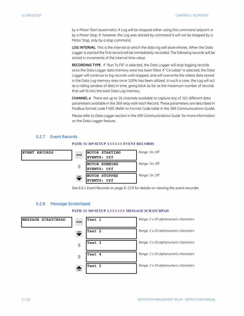
5–118 369 MOTOR MANAGEMENT RELAY– INSTRUCTION MANUAL
S1 369 SETUP CHAPTER 5: SETPOINTS
by a Motor Start (automatic). A Log will be stopped either using this command setpoint or by a Motor Stop. If, however, the Log was started by command it will not be stopped by a Motor Stop, only by a stop command.
LOG INTERVAL: This is the interval at which the data log will store entries. When the Data Logger is started the first record will be immediately recorded. The following records will be stored in increments of the interval time value.
RECORDING TYPE: If “Run To Fill” is selected, the Data Logger will stop logging records once the Data Logger data memory area has been filled. If “Circulate” is selected, the Data Logger will continue to log records until stopped, and will overwrite the oldest data stored in the Data Log memory area once 100% has been utilized. In such a case, the Log will act as a rolling window of data in time, going back as far as the maximum number of records that will fit into the total Data Log memory.
CHANNEL x: There are up to 16 channels available to capture any of 101 different data parameters available in the 369 relay with each Record. These parameters are described in Modbus format code F189. (Refer to Format Code table in the 369 Communications Guide).
Please refer to Data Logger section in the 369 Communications Guide for more information on the Data Logger feature.
5.2.7 Event RecordsPATH: S1 369 SETUP EVENT RECORDS
See 6.6.1 Event Records on page 6–219 for details on viewing the event recorder.
5.2.8 Message ScratchpadPATH: S1 369 SETUP MESSAGE SCRATCHPAD
EVENT RECORDS MOTOR STARTINGEVENTS: Off
Range: On, Off
MOTOR RUNNINGEVENTS: Off
Range: On, Off
MOTOR STOPPEDEVENTS: Off
Range: On, Off
MESSAGE SCRATCHPAD Text 1 Range: 2 x 20 alphanumeric characters
Text 2 Range: 2 x 20 alphanumeric characters
Text 3 Range: 2 x 20 alphanumeric characters
Text 4 Range: 2 x 20 alphanumeric characters
Text 5 Range: 2 x 20 alphanumeric characters
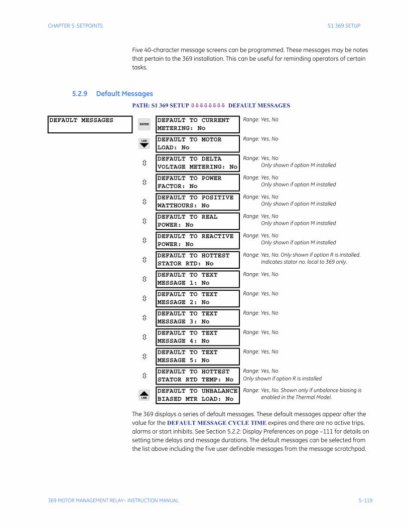
CHAPTER 5: SETPOINTS S1 369 SETUP
369 MOTOR MANAGEMENT RELAY– INSTRUCTION MANUAL 5–119
Five 40-character message screens can be programmed. These messages may be notes that pertain to the 369 installation. This can be useful for reminding operators of certain tasks.
5.2.9 Default MessagesPATH: S1 369 SETUP DEFAULT MESSAGES
The 369 displays a series of default messages. These default messages appear after the value for the DEFAULT MESSAGE CYCLE TIME expires and there are no active trips, alarms or start inhibits. See Section 5.2.2: Display Preferences on page –111 for details on setting time delays and message durations. The default messages can be selected from the list above including the five user definable messages from the message scratchpad.
DEFAULT MESSAGES DEFAULT TO CURRENTMETERING: No
Range: Yes, No
DEFAULT TO MOTORLOAD: No
Range: Yes, No
DEFAULT TO DELTAVOLTAGE METERING: No
Range: Yes, NoOnly shown if option M installed
DEFAULT TO POWERFACTOR: No
Range: Yes, NoOnly shown if option M installed
DEFAULT TO POSITIVEWATTHOURS: No
Range: Yes, NoOnly shown if option M installed
DEFAULT TO REALPOWER: No
Range: Yes, NoOnly shown if option M installed
DEFAULT TO REACTIVEPOWER: No
Range: Yes, NoOnly shown if option M installed
DEFAULT TO HOTTESTSTATOR RTD: No
Range: Yes, No. Only shown if option R is installed. Indicates stator no. local to 369 only.
DEFAULT TO TEXTMESSAGE 1: No
Range: Yes, No
DEFAULT TO TEXTMESSAGE 2: No
Range: Yes, No
DEFAULT TO TEXTMESSAGE 3: No
Range: Yes, No
DEFAULT TO TEXTMESSAGE 4: No
Range: Yes, No
DEFAULT TO TEXTMESSAGE 5: No
Range: Yes, No
DEFAULT TO HOTTESTSTATOR RTD TEMP: No
Range: Yes, NoOnly shown if option R is installed
DEFAULT TO UNBALANCEBIASED MTR LOAD: No
Range: Yes, No. Shown only if unbalance biasing is enabled in the Thermal Model.
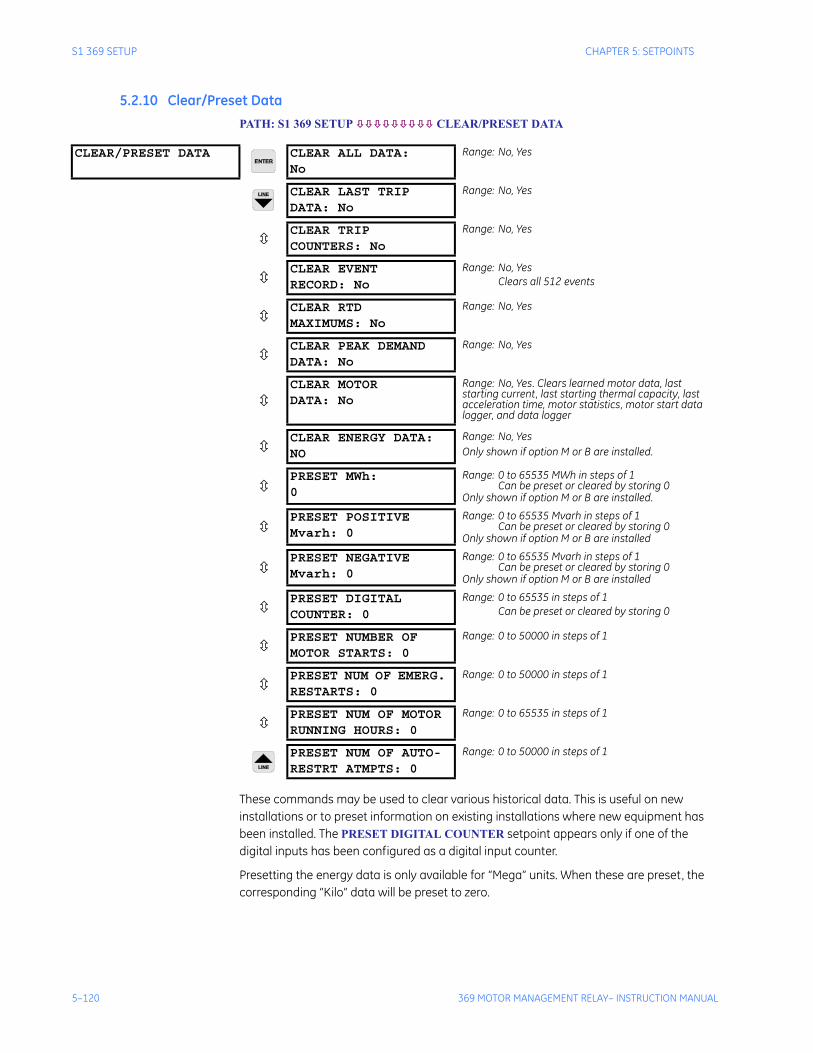
5–120 369 MOTOR MANAGEMENT RELAY– INSTRUCTION MANUAL
S1 369 SETUP CHAPTER 5: SETPOINTS
5.2.10 Clear/Preset DataPATH: S1 369 SETUP CLEAR/PRESET DATA
These commands may be used to clear various historical data. This is useful on new installations or to preset information on existing installations where new equipment has been installed. The PRESET DIGITAL COUNTER setpoint appears only if one of the digital inputs has been configured as a digital input counter.
Presetting the energy data is only available for “Mega” units. When these are preset, the corresponding “Kilo” data will be preset to zero.
CLEAR/PRESET DATA CLEAR ALL DATA:No
Range: No, Yes
CLEAR LAST TRIPDATA: No
Range: No, Yes
CLEAR TRIPCOUNTERS: No
Range: No, Yes
CLEAR EVENTRECORD: No
Range: No, YesClears all 512 events
CLEAR RTDMAXIMUMS: No
Range: No, Yes
CLEAR PEAK DEMANDDATA: No
Range: No, Yes
CLEAR MOTORDATA: No
Range: No, Yes. Clears learned motor data, last starting current, last starting thermal capacity, last acceleration time, motor statistics, motor start data logger, and data logger
CLEAR ENERGY DATA:NO
Range: No, YesOnly shown if option M or B are installed.
PRESET MWh: 0
Range: 0 to 65535 MWh in steps of 1Can be preset or cleared by storing 0
Only shown if option M or B are installed.
PRESET POSITIVEMvarh: 0
Range: 0 to 65535 Mvarh in steps of 1Can be preset or cleared by storing 0
Only shown if option M or B are installed
PRESET NEGATIVEMvarh: 0
Range: 0 to 65535 Mvarh in steps of 1Can be preset or cleared by storing 0
Only shown if option M or B are installed
PRESET DIGITALCOUNTER: 0
Range: 0 to 65535 in steps of 1Can be preset or cleared by storing 0
PRESET NUMBER OF MOTOR STARTS: 0
Range: 0 to 50000 in steps of 1
PRESET NUM OF EMERG. RESTARTS: 0
Range: 0 to 50000 in steps of 1
PRESET NUM OF MOTOR RUNNING HOURS: 0
Range: 0 to 65535 in steps of 1
PRESET NUM OF AUTO-RESTRT ATMPTS: 0
Range: 0 to 50000 in steps of 1
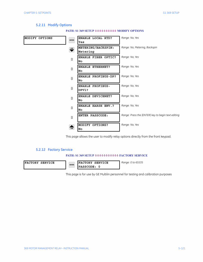
CHAPTER 5: SETPOINTS S1 369 SETUP
369 MOTOR MANAGEMENT RELAY– INSTRUCTION MANUAL 5–121
5.2.11 Modify OptionsPATH: S1 369 SETUP MODIFY OPTIONS
This page allows the user to modify relay options directly from the front keypad.
5.2.12 Factory ServicePATH: S1 369 SETUP FACTORY SERVICE
This page is for use by GE Multilin personnel for testing and calibration purposes
MODIFY OPTIONS ENABLE LOCAL RTD?Yes
Range: No, Yes
METERING/BACKSPIN:Metering
Range: No, Metering, Backspin
ENABLE FIBER OPTIC?No
Range: No, Yes
ENABLE ETHERNET?No
Range: No, Yes
ENABLE PROFIBUS-DP?No
Range: No, Yes
ENABLE PROFIBUS-DPV1?
Range: No, Yes
ENABLE DEVICENET?No
Range: No, Yes
ENABLE HARSH ENV.?No
Range: No, Yes
ENTER PASSCODE: Range: Press the [ENTER] key to begin text editing
MODIFY OPTIONS?No
Range: No, Yes
FACTORY SERVICE FACTORY SERVICEPASSCODE: 0
Range: 0 to 65535
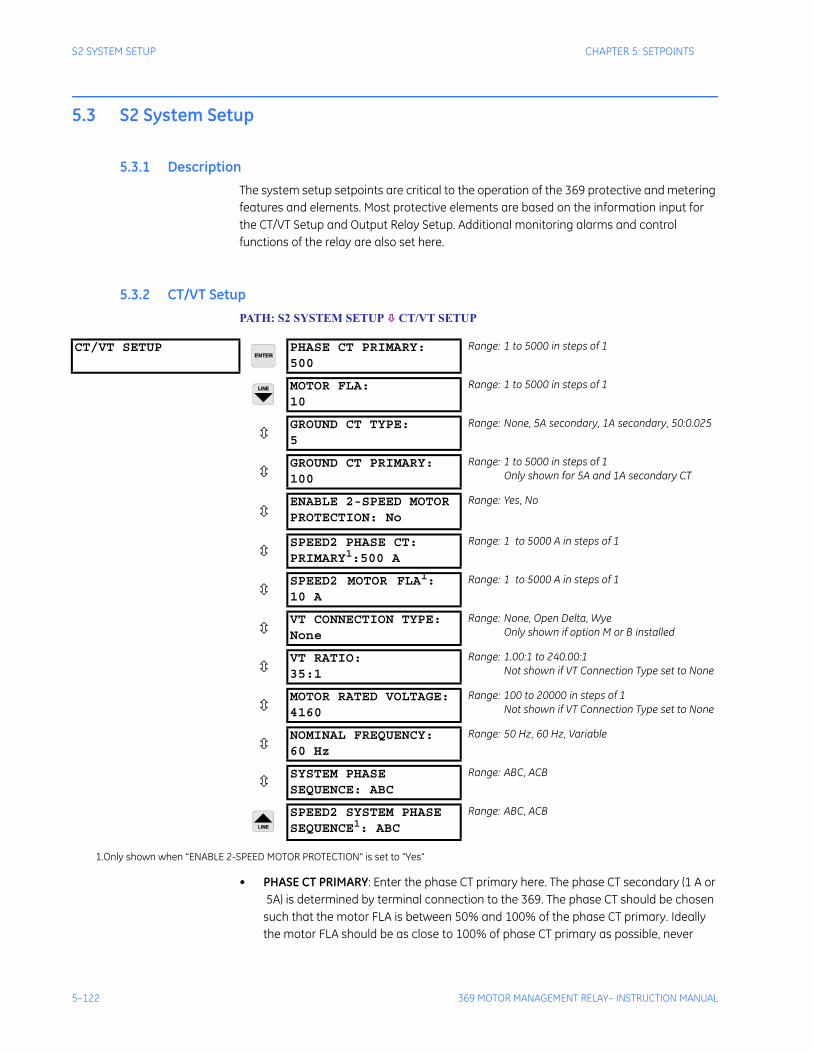
5–122 369 MOTOR MANAGEMENT RELAY– INSTRUCTION MANUAL
S2 SYSTEM SETUP CHAPTER 5: SETPOINTS
5.3 S2 System Setup
5.3.1 DescriptionThe system setup setpoints are critical to the operation of the 369 protective and metering features and elements. Most protective elements are based on the information input for the CT/VT Setup and Output Relay Setup. Additional monitoring alarms and control functions of the relay are also set here.
5.3.2 CT/VT SetupPATH: S2 SYSTEM SETUP CT/VT SETUP
• PHASE CT PRIMARY: Enter the phase CT primary here. The phase CT secondary (1 A or 5A) is determined by terminal connection to the 369. The phase CT should be chosen
such that the motor FLA is between 50% and 100% of the phase CT primary. Ideally the motor FLA should be as close to 100% of phase CT primary as possible, never
CT/VT SETUP PHASE CT PRIMARY:500
Range: 1 to 5000 in steps of 1
MOTOR FLA:10
Range: 1 to 5000 in steps of 1
GROUND CT TYPE:5
Range: None, 5A secondary, 1A secondary, 50:0.025
GROUND CT PRIMARY:100
Range: 1 to 5000 in steps of 1Only shown for 5A and 1A secondary CT
ENABLE 2-SPEED MOTORPROTECTION: No
Range: Yes, No
SPEED2 PHASE CT: PRIMARY1:500 A
Range: 1 to 5000 A in steps of 1
SPEED2 MOTOR FLA1:10 A
Range: 1 to 5000 A in steps of 1
VT CONNECTION TYPE:None
Range: None, Open Delta, WyeOnly shown if option M or B installed
VT RATIO:35:1
Range: 1.00:1 to 240.00:1Not shown if VT Connection Type set to None
MOTOR RATED VOLTAGE:4160
Range: 100 to 20000 in steps of 1Not shown if VT Connection Type set to None
NOMINAL FREQUENCY:60 Hz
Range: 50 Hz, 60 Hz, Variable
SYSTEM PHASESEQUENCE: ABC
Range: ABC, ACB
SPEED2 SYSTEM PHASE SEQUENCE1: ABC
Range: ABC, ACB
1.Only shown when “ENABLE 2-SPEED MOTOR PROTECTION” is set to “Yes”

CHAPTER 5: SETPOINTS S2 SYSTEM SETUP
369 MOTOR MANAGEMENT RELAY– INSTRUCTION MANUAL 5–123
more. The phase CT class or type should also be chosen such that the CT can handle the maximum potential fault current with the attached burden without having its output saturate. Information on how to determine this if required is available in Section 7.4: CT Specification and Selection on page –230.
• MOTOR FLA: The motor FLA (full load amps or full load current) must be entered. This value may be taken from the motor nameplate or motor data sheets.
• GROUND CT TYPE and GROUND CT PRIMARY: The GROUND CT TYPE and GROUND CT PRIMARY (if 5 A or 1 A secondary) must be entered here. For high resistance grounded systems, sensitive ground detection is possible with the 50:0.025 CT. On solidly or low resistance grounded systems where fault current can be quite high, a 1 A or 5 A CT should be used for either zero-sequence (core balance) or residual ground sensing. If a residual connection is used with the phase CTs, the phase CT primary must also be entered for the ground CT primary. As with the phase CTs the type of ground CT should be chosen to handle all potential fault levels without saturating.
• ENABLE 2-SPEED MOTOR: If set to Yes, the following new settings are shown:
1. S2 SYSTEM SETUP/ CT/VT SETUP: SPEED2 PHASE CT SPEED2 MOTOR FLA SPEED2 PHASE SEQUENCE
2. S12 TWO SPEED MOTOR: SPEED2 O/L CURVES SPEED2 UNDERCURRENTSPEED2 ACCELERATION
3. S9 DIGITAL INPUTS/ SPEED SWITCH displays the message TWO SPEED MONITOR. The Speed Switch option is added to setting range for: S9 DIGITAL INPUTS/ EMERGENCY RESTART S9 DIGITAL INPUTS/DIFFERENTIAL SWITCH S9 DIGITAL INPUTS/REMOTE RESET.
• SPEED2 PHASE CT: This setting specifies the CT primary of the CT used under Speed 2. When in Speed 1, the existing CT primary found under S2 SYSTEM SETUP/ CT/VT SETUP/PHASE CT PRIMARY is in effect.
• SPEED2 MOTOR FLA: This setting specifies the FLA of the motor running at Speed 2. When in Speed 1, the existing FLA found under S2 SYSTEM SETUP/ CT/VT SETUP/MOTOR FLA is in effect.
• VT CONNECTION TYPE, VT RATIO, and MOTOR RATED VOLTAGE: These voltage related setpoints are visible only if the 369 has metering installed.
The manner in which the voltage transformers are connected must be entered here or none if VTs are not used. The VT turns ratio must be chosen such that the secondary voltage of the VTs is between 1 and 240 V when the primary is at motor nameplate voltage. All voltage protection features are programmed as a percent of motor nameplate or rated voltage which represents the rated motor design voltage line to line.
For example: If the motor nameplate voltage is 4160 V and the VTs are 4160/120 open-delta, program VT CONNECTION TYPE to “Open Delta”, VT RATIO to “34.67:1”, and MOTOR RATED VOLTAGE to “4160 V”.

5–124 369 MOTOR MANAGEMENT RELAY– INSTRUCTION MANUAL
S2 SYSTEM SETUP CHAPTER 5: SETPOINTS
• NOMINAL FREQUENCY: Enter the nominal system frequency here.
The 369 has variable frequency functionality when the NOMINAL FREQUENCY is set to “Variable”. All of the elements function in the same manner with the exception of the voltage and power elements, which work properly if the voltage waveform is approximately sinusoidal. When using a pulse width modulate drive, and an unfiltered voltage waveform is present, the unit will not be able to accurately measure voltage, but an approximately sinusoidal current waveform can be measured accurately. If the NOMINAL FREQUENCY is set to “Variable”, the filtering algorithm could increase the trip and alarm times for the undervoltage and underfrequency elements by up to 270 ms. If the level exceeds the threshold by a significant amount, trip and alarm times will decrease until they match the programmed delay. The exceptions to this increased time are the short circuit and ground fault elements, which will trip as per specification.
Note that when the NOMINAL FREQUENCY setting is “Variable”, the element pickup levels and timing are based on the measured values of the 369.
Frequency is normally determined from the Va voltage input. If however this voltage drops below the minimum voltage threshold the Ia current input will be used.
• SYSTEM PHASE SEQUENCE: If the phase sequence for a given system is ACB rather than the standard ABC the phase sequence may be changed. This setpoint allows the 369 to properly calculate phase reversal and power quantities.
Note In motor Forward/Reverse applications, for proper power metering and phase reversal trip protection, the system phase sequence must be set the same as the phase sequence for the forward rotation of the motor.
• SPEED2 PHASE SEQUENCE: This setting specifies the phase rotation when running in Speed 2. When in Speed 1, the phase rotation set under S2 SYSTEM SETUP/ CT/VT SETUP/SYSTEM PHASE SEQUENCE is in effect. The FLA rating defines the nominal loading of the motor, and differs depending on motor speed. If ENABLE 2-SPEED MOTOR is set to “Yes”, and Speed Switch (TWO SPEED MONITOR) digital input is detected “closed”, the relay automatically applies the SPEED2 CT PRIMARY and SPEED2 FLA settings to all motor features that previously were configured to utilize the Speed 1 settings: Thermal Model OVERLOAD PICKUP LEVEL, OVERLOAD ALARM, SHORT CIRCUIT, MECHANICAL JAM, CURRENT UNBALANCE, and SPEED2 UNDERCURRENT. The 369 relay uses one Thermal Model for both speeds, and keeps the accumulated thermal capacity during speed switching. Upon detection of Speed 2, the phase sequence setting under SYSTEM SETUP/CT/VT SETUP/SPEED2 SYSTEM PHASE SEQUENCE is used for power metering calculations. For 2-speed motors rotating in the same direction (typically low/high-speed applications) when in Speed 1 and Speed 2, the settings under SYSTEM SETUP/CT/VT SETUP/SYSTEM PHASE SEQUENCE and under SYSTEM SETUP/CT/VT SETUP/SPEED2 PHASE SEQUENCE are set the same.For 2-speed motors changing the rotating direction (motor Forward/Reverse applications), the setting ABC (ACB) under SYSTEM SETUP/CT/VT SETUP/SPEED2 PHASE SEQUENCE is set to be different than the setting ACB (ACB) under SYSTEM SETUP/CT/VT SETUP/SYSTEM PHASE SEQUENCE. For these applications, the motor is rotating with the same speed, but is designed and controlled to rotate in both Forward and Reverse directions.
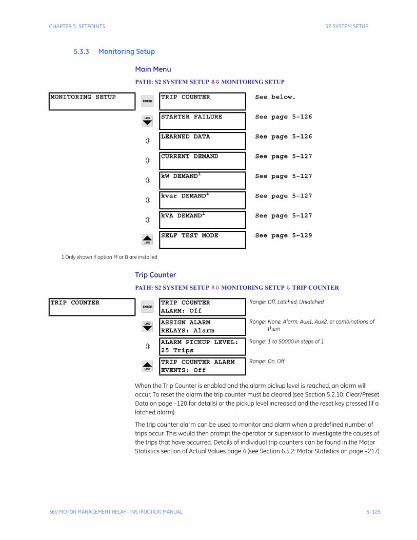
CHAPTER 5: SETPOINTS S2 SYSTEM SETUP
369 MOTOR MANAGEMENT RELAY– INSTRUCTION MANUAL 5–125
5.3.3 Monitoring Setup
Main Menu
PATH: S2 SYSTEM SETUP MONITORING SETUP
Trip Counter
PATH: S2 SYSTEM SETUP MONITORING SETUP TRIP COUNTER
When the Trip Counter is enabled and the alarm pickup level is reached, an alarm will occur. To reset the alarm the trip counter must be cleared (see Section 5.2.10: Clear/Preset Data on page –120 for details) or the pickup level increased and the reset key pressed (if a latched alarm).
The trip counter alarm can be used to monitor and alarm when a predefined number of trips occur. This would then prompt the operator or supervisor to investigate the causes of the trips that have occurred. Details of individual trip counters can be found in the Motor Statistics section of Actual Values page 4 (see Section 6.5.2: Motor Statistics on page –217).
MONITORING SETUP TRIP COUNTER See below.
STARTER FAILURE See page 5–126
LEARNED DATA See page 5–126
CURRENT DEMAND See page 5–127
kW DEMAND1 See page 5–127
kvar DEMAND1 See page 5–127
kVA DEMAND1 See page 5–127
SELF TEST MODE See page 5–129
1.Only shown if option M or B are installed
TRIP COUNTER TRIP COUNTERALARM: Off
Range: Off, Latched, Unlatched
ASSIGN ALARMRELAYS: Alarm
Range: None, Alarm, Aux1, Aux2, or combinations of them
ALARM PICKUP LEVEL:25 Trips
Range: 1 to 50000 in steps of 1
TRIP COUNTER ALARMEVENTS: Off
Range: On, Off
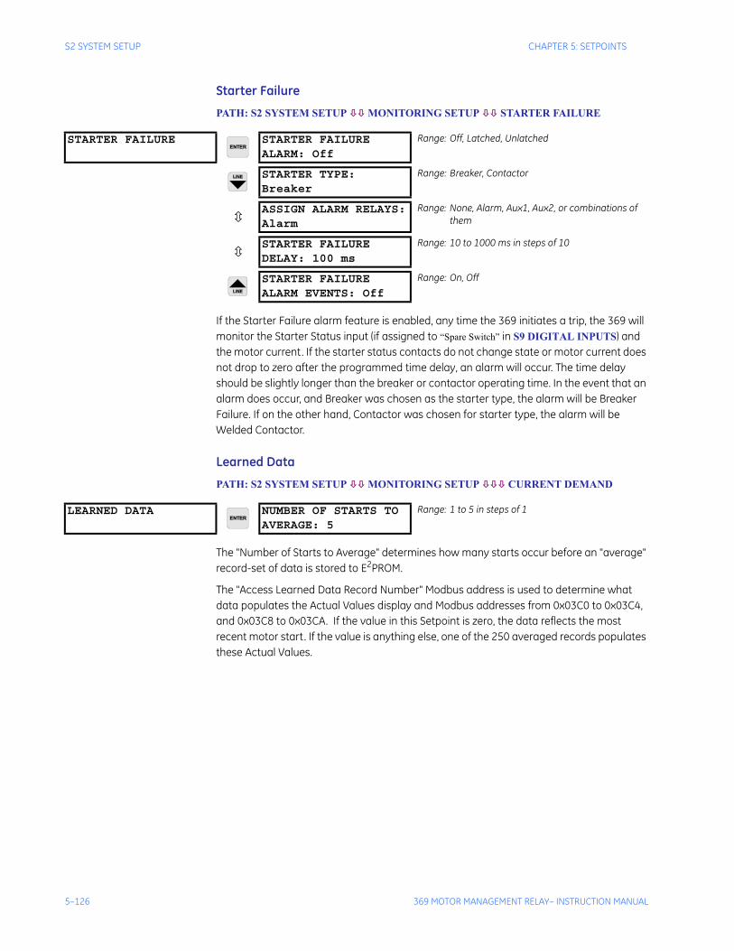
5–126 369 MOTOR MANAGEMENT RELAY– INSTRUCTION MANUAL
S2 SYSTEM SETUP CHAPTER 5: SETPOINTS
Starter Failure
PATH: S2 SYSTEM SETUP MONITORING SETUP STARTER FAILURE
If the Starter Failure alarm feature is enabled, any time the 369 initiates a trip, the 369 will monitor the Starter Status input (if assigned to “Spare Switch” in S9 DIGITAL INPUTS) and the motor current. If the starter status contacts do not change state or motor current does not drop to zero after the programmed time delay, an alarm will occur. The time delay should be slightly longer than the breaker or contactor operating time. In the event that an alarm does occur, and Breaker was chosen as the starter type, the alarm will be Breaker Failure. If on the other hand, Contactor was chosen for starter type, the alarm will be Welded Contactor.
Learned Data
PATH: S2 SYSTEM SETUP MONITORING SETUP CURRENT DEMAND
The "Number of Starts to Average" determines how many starts occur before an "average" record-set of data is stored to E2PROM.
The "Access Learned Data Record Number" Modbus address is used to determine what data populates the Actual Values display and Modbus addresses from 0x03C0 to 0x03C4, and 0x03C8 to 0x03CA. If the value in this Setpoint is zero, the data reflects the most recent motor start. If the value is anything else, one of the 250 averaged records populates these Actual Values.
STARTER FAILURE STARTER FAILUREALARM: Off
Range: Off, Latched, Unlatched
STARTER TYPE:Breaker
Range: Breaker, Contactor
ASSIGN ALARM RELAYS:Alarm
Range: None, Alarm, Aux1, Aux2, or combinations of them
STARTER FAILUREDELAY: 100 ms
Range: 10 to 1000 ms in steps of 10
STARTER FAILUREALARM EVENTS: Off
Range: On, Off
LEARNED DATA NUMBER OF STARTS TO AVERAGE: 5
Range: 1 to 5 in steps of 1
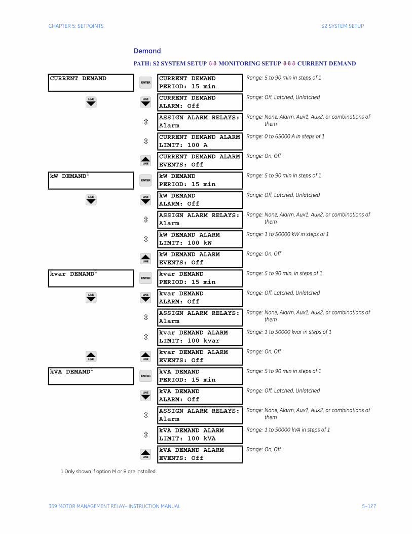
CHAPTER 5: SETPOINTS S2 SYSTEM SETUP
369 MOTOR MANAGEMENT RELAY– INSTRUCTION MANUAL 5–127
Demand
PATH: S2 SYSTEM SETUP MONITORING SETUP CURRENT DEMAND
CURRENT DEMAND CURRENT DEMANDPERIOD: 15 min
Range: 5 to 90 min in steps of 1
CURRENT DEMANDALARM: Off
Range: Off, Latched, Unlatched
ASSIGN ALARM RELAYS:Alarm
Range: None, Alarm, Aux1, Aux2, or combinations of them
CURRENT DEMAND ALARMLIMIT: 100 A
Range: 0 to 65000 A in steps of 1
CURRENT DEMAND ALARMEVENTS: Off
Range: On, Off
kW DEMAND1 kW DEMANDPERIOD: 15 min
Range: 5 to 90 min in steps of 1
kW DEMANDALARM: Off
Range: Off, Latched, Unlatched
ASSIGN ALARM RELAYS:Alarm
Range: None, Alarm, Aux1, Aux2, or combinations of them
kW DEMAND ALARMLIMIT: 100 kW
Range: 1 to 50000 kW in steps of 1
kW DEMAND ALARMEVENTS: Off
Range: On, Off
kvar DEMAND1 kvar DEMANDPERIOD: 15 min
Range: 5 to 90 min. in steps of 1
kvar DEMANDALARM: Off
Range: Off, Latched, Unlatched
ASSIGN ALARM RELAYS:Alarm
Range: None, Alarm, Aux1, Aux2, or combinations of them
kvar DEMAND ALARMLIMIT: 100 kvar
Range: 1 to 50000 kvar in steps of 1
kvar DEMAND ALARMEVENTS: Off
Range: On, Off
kVA DEMAND1 kVA DEMANDPERIOD: 15 min
Range: 5 to 90 min in steps of 1
kVA DEMANDALARM: Off
Range: Off, Latched, Unlatched
ASSIGN ALARM RELAYS:Alarm
Range: None, Alarm, Aux1, Aux2, or combinations of them
kVA DEMAND ALARMLIMIT: 100 kVA
Range: 1 to 50000 kVA in steps of 1
kVA DEMAND ALARMEVENTS: Off
Range: On, Off
1.Only shown if option M or B are installed
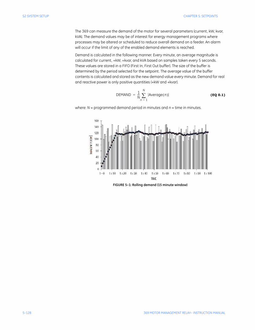
5–128 369 MOTOR MANAGEMENT RELAY– INSTRUCTION MANUAL
S2 SYSTEM SETUP CHAPTER 5: SETPOINTS
The 369 can measure the demand of the motor for several parameters (current, kW, kvar, kVA). The demand values may be of interest for energy management programs where processes may be altered or scheduled to reduce overall demand on a feeder. An alarm will occur if the limit of any of the enabled demand elements is reached.
Demand is calculated in the following manner. Every minute, an average magnitude is calculated for current, +kW, +kvar, and kVA based on samples taken every 5 seconds. These values are stored in a FIFO (First In, First Out buffer). The size of the buffer is determined by the period selected for the setpoint. The average value of the buffer contents is calculated and stored as the new demand value every minute. Demand for real and reactive power is only positive quantities (+kW and +kvar).
(EQ 0.1)
where: N = programmed demand period in minutes and n = time in minutes.
FIGURE 5–1: Rolling demand (15 minute window)
DEMAND 1N--- Average n( )
n 1=
N
∑=
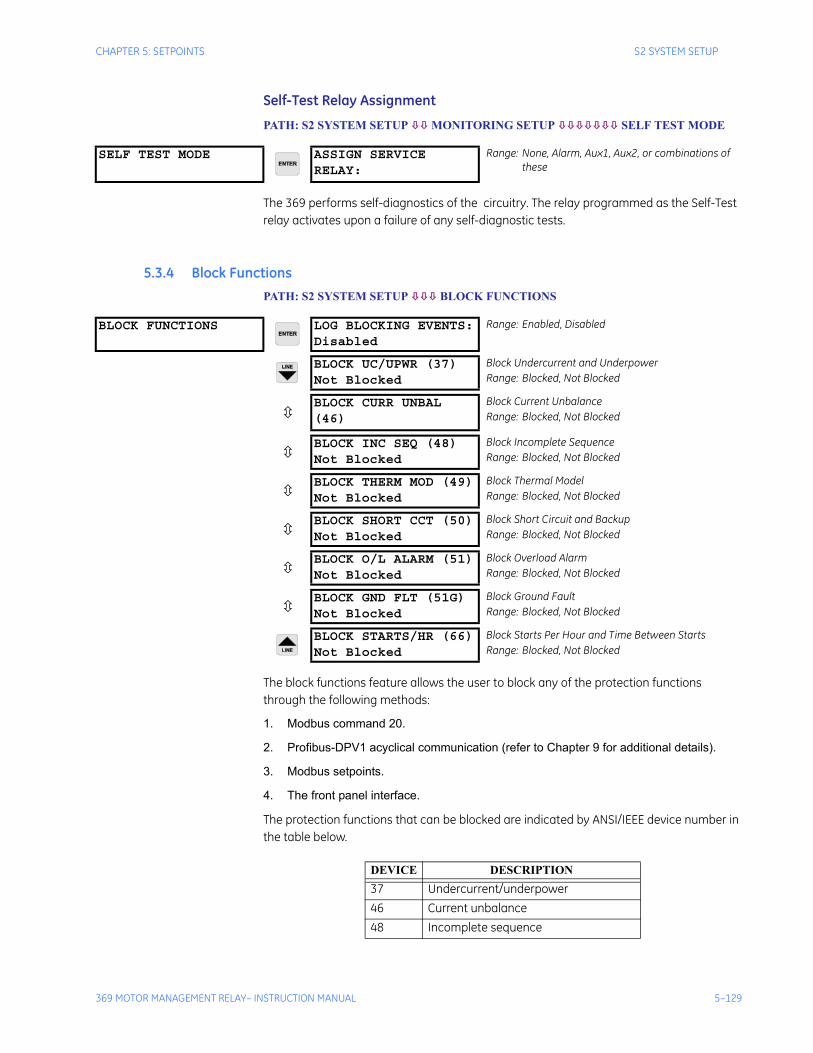
CHAPTER 5: SETPOINTS S2 SYSTEM SETUP
369 MOTOR MANAGEMENT RELAY– INSTRUCTION MANUAL 5–129
Self-Test Relay Assignment
PATH: S2 SYSTEM SETUP MONITORING SETUP SELF TEST MODE
The 369 performs self-diagnostics of the circuitry. The relay programmed as the Self-Test relay activates upon a failure of any self-diagnostic tests.
5.3.4 Block FunctionsPATH: S2 SYSTEM SETUP BLOCK FUNCTIONS
The block functions feature allows the user to block any of the protection functions through the following methods:
1. Modbus command 20.
2. Profibus-DPV1 acyclical communication (refer to Chapter 9 for additional details).
3. Modbus setpoints.
4. The front panel interface.
The protection functions that can be blocked are indicated by ANSI/IEEE device number in the table below.
SELF TEST MODE ASSIGN SERVICE RELAY:
Range: None, Alarm, Aux1, Aux2, or combinations of these
BLOCK FUNCTIONS LOG BLOCKING EVENTS:Disabled
Range: Enabled, Disabled
BLOCK UC/UPWR (37)Not Blocked
Block Undercurrent and UnderpowerRange: Blocked, Not Blocked
BLOCK CURR UNBAL (46)
Block Current UnbalanceRange: Blocked, Not Blocked
BLOCK INC SEQ (48)Not Blocked
Block Incomplete SequenceRange: Blocked, Not Blocked
BLOCK THERM MOD (49)Not Blocked
Block Thermal ModelRange: Blocked, Not Blocked
BLOCK SHORT CCT (50)Not Blocked
Block Short Circuit and BackupRange: Blocked, Not Blocked
BLOCK O/L ALARM (51)Not Blocked
Block Overload AlarmRange: Blocked, Not Blocked
BLOCK GND FLT (51G)Not Blocked
Block Ground FaultRange: Blocked, Not Blocked
BLOCK STARTS/HR (66)Not Blocked
Block Starts Per Hour and Time Between StartsRange: Blocked, Not Blocked
DEVICE DESCRIPTION37 Undercurrent/underpower46 Current unbalance48 Incomplete sequence
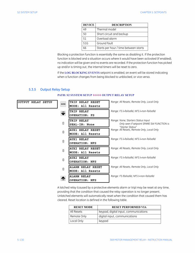
5–130 369 MOTOR MANAGEMENT RELAY– INSTRUCTION MANUAL
S2 SYSTEM SETUP CHAPTER 5: SETPOINTS
Blocking a protection function is essentially the same as disabling it . If the protection function is blocked and a situation occurs where it would have been activated (if enabled), no indication will be given and no events are recorded. If the protection function has picked up and/or is timing out, the internal timers will be reset to zero.
If the LOG BLOCKING EVENTS setpoint is enabled, an event will be stored indicating when a function changes from being blocked to unblocked, or vice versa.
5.3.5 Output Relay SetupPATH: S2 SYSTEM SETUP OUTPUT RELAY SETUP
A latched relay (caused by a protective elements alarm or trip) may be reset at any time, providing that the condition that caused the relay operation is no longer present. Unlatched elements will automatically reset when the condition that caused them has cleared. Reset location is defined in the following table.
49 Thermal model50 Short circuit and backup51 Overload alarm51G Ground fault66 Starts per hour / time between starts
DEVICE DESCRIPTION
OUTPUT RELAY SETUP TRIP RELAY RESETMODE: All Resets
Range: All Resets, Remote Only, Local Only
TRIP RELAYOPERATION: FS
Range: FS (=failsafe), NFS (=non-failsafe)
TRIP RELAYSEAL-IN: None
Range: None, Starters Status InputOnly seen if setpoint SPARE SW FUNCTION is "Starter Status"
AUX1 RELAY RESETMODE: All Resets
Range: All Resets, Remote Only, Local Only
AUX1 RELAYOPERATION: NFS
Range: FS (=failsafe), NFS (=non-failsafe)
AUX2 RELAY RESETMODE: All Resets
Range: All Resets, Remote Only, Local Only
AUX2 RELAYOPERATION: NFS
Range: FS (=failsafe), NFS (=non-failsafe)
ALARM RELAY RESETMODE: All Resets
Range: All Resets, Remote Only, Local Only
ALARM RELAYOPERATION: NFS
Range: FS (failsafe), NFS (=non-failsafe)
RESET MODE RESET PERFORMED VIAAll Resets keypad, digital input, communicationsRemote Only digital input, communicationsLocal Only keypad
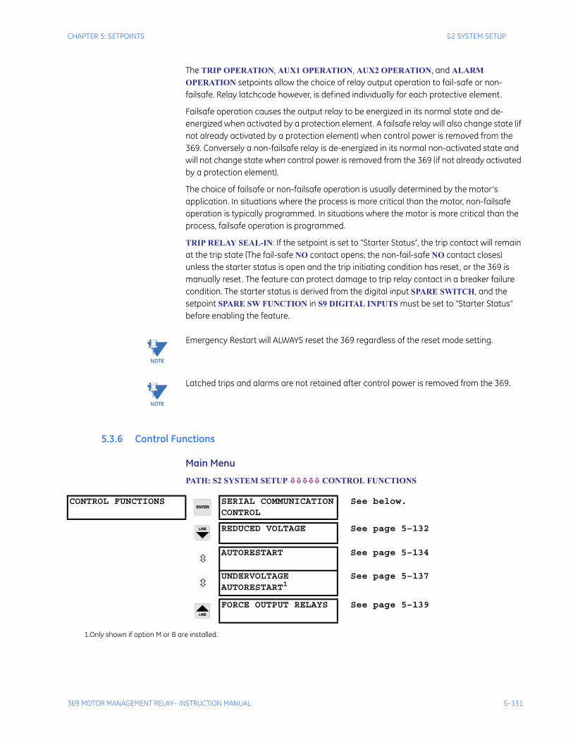
CHAPTER 5: SETPOINTS S2 SYSTEM SETUP
369 MOTOR MANAGEMENT RELAY– INSTRUCTION MANUAL 5–131
The TRIP OPERATION, AUX1 OPERATION, AUX2 OPERATION, and ALARM OPERATION setpoints allow the choice of relay output operation to fail-safe or non-failsafe. Relay latchcode however, is defined individually for each protective element.
Failsafe operation causes the output relay to be energized in its normal state and de-energized when activated by a protection element. A failsafe relay will also change state (if not already activated by a protection element) when control power is removed from the 369. Conversely a non-failsafe relay is de-energized in its normal non-activated state and will not change state when control power is removed from the 369 (if not already activated by a protection element).
The choice of failsafe or non-failsafe operation is usually determined by the motor’s application. In situations where the process is more critical than the motor, non-failsafe operation is typically programmed. In situations where the motor is more critical than the process, failsafe operation is programmed.
TRIP RELAY SEAL-IN: If the setpoint is set to “Starter Status”, the trip contact will remain at the trip state (The fail-safe NO contact opens; the non-fail-safe NO contact closes) unless the starter status is open and the trip initiating condition has reset, or the 369 is manually reset. The feature can protect damage to trip relay contact in a breaker failure condition. The starter status is derived from the digital input SPARE SWITCH, and the setpoint SPARE SW FUNCTION in S9 DIGITAL INPUTS must be set to “Starter Status” before enabling the feature.
Note Emergency Restart will ALWAYS reset the 369 regardless of the reset mode setting.
Note Latched trips and alarms are not retained after control power is removed from the 369.
5.3.6 Control Functions
Main Menu
PATH: S2 SYSTEM SETUP CONTROL FUNCTIONS
CONTROL FUNCTIONS SERIAL COMMUNICATIONCONTROL
See below.
REDUCED VOLTAGE See page 5–132
AUTORESTART See page 5–134
UNDERVOLTAGEAUTORESTART1
See page 5–137
FORCE OUTPUT RELAYS See page 5–139
1.Only shown if option M or B are installed.
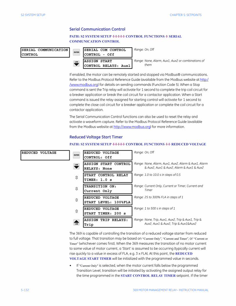
5–132 369 MOTOR MANAGEMENT RELAY– INSTRUCTION MANUAL
S2 SYSTEM SETUP CHAPTER 5: SETPOINTS
Serial Communication Control
PATH: S2 SYSTEM SETUP CONTROL FUNCTIONS SERIAL COMMUNICATION CONTROL
If enabled, the motor can be remotely started and stopped via Modbus® communications. Refer to the Modbus Protocol Reference Guide (available from the Modbus website at http://www.modbus.org) for details on sending commands (Function Code 5). When a Stop command is sent the Trip relay will activate for 1 second to complete the trip coil circuit for a breaker application or break the coil circuit for a contactor application. When a Start command is issued the relay assigned for starting control will activate for 1 second to complete the close coil circuit for a breaker application or complete the coil circuit for a contactor application.
The Serial Communication Control functions can also be used to reset the relay and activate a waveform capture. Refer to the Modbus Protocol Reference Guide (available from the Modbus website at http://www.modbus.org) for more information.
Reduced Voltage Start Timer
PATH: S2 SYSTEM SETUP CONTROL FUNCTIONS REDUCED VOLTAGE
The 369 is capable of controlling the transition of a reduced voltage starter from reduced to full voltage. That transition may be based on “Current Only”, “Current and Timer”, or “Current or Timer” (whichever comes first). When the 369 measures the transition of no motor current to some value of motor current, a 'Start' is assumed to be occurring (typically current will rise quickly to a value in excess of FLA, e.g. 3 x FLA). At this point, the REDUCED VOLTAGE START TIMER will be initialized with the programmed value in seconds.
• If "Current Only" is selected, when the motor current falls below the programmed Transition Level, transition will be initiated by activating the assigned output relay for the time programmed in the START CONTROL RELAY TIMER setpoint. If the timer
SERIAL COMMUNICATIONCONTROL
SERIAL COM CONTROLCONTROL - Off
Range: On, Off
ASSIGN STARTCONTROL RELAYS: Aux1
Range: None, Alarm, Aux1, Aux2 or combinations of them
REDUCED VOLTAGE REDUCED VOLTAGECONTROL: Off
Range: On, Off
ASSIGN START CONTROLRELAYS: None
Range: None, Alarm, Aux1, Aux2, Alarm & Aux1, Alarm & Aux2, Aux1 & Aux2, Alarm & Aux1 & Aux2
START CONTROL RELAYTIMER: 1.0 s
Range: 1.0 to 10.0 s in steps of 0.5
TRANSITION ON:Current Only
Range: Current Only, Current or Timer, Current and Timer
REDUCED VOLTAGESTART LEVEL: 100%FLA
Range: 25 to 300% FLA in steps of 1
REDUCED VOLTAGESTART TIMER: 200 s
Range: 1 to 500 s in steps of 1
ASSIGN TRIP RELAYS:Trip
Range: None, Trip, Aux1, Aux2, Trip & Aux1, Trip & Aux2, Aux1 & Aux2, Trip & Aux1&Aux2
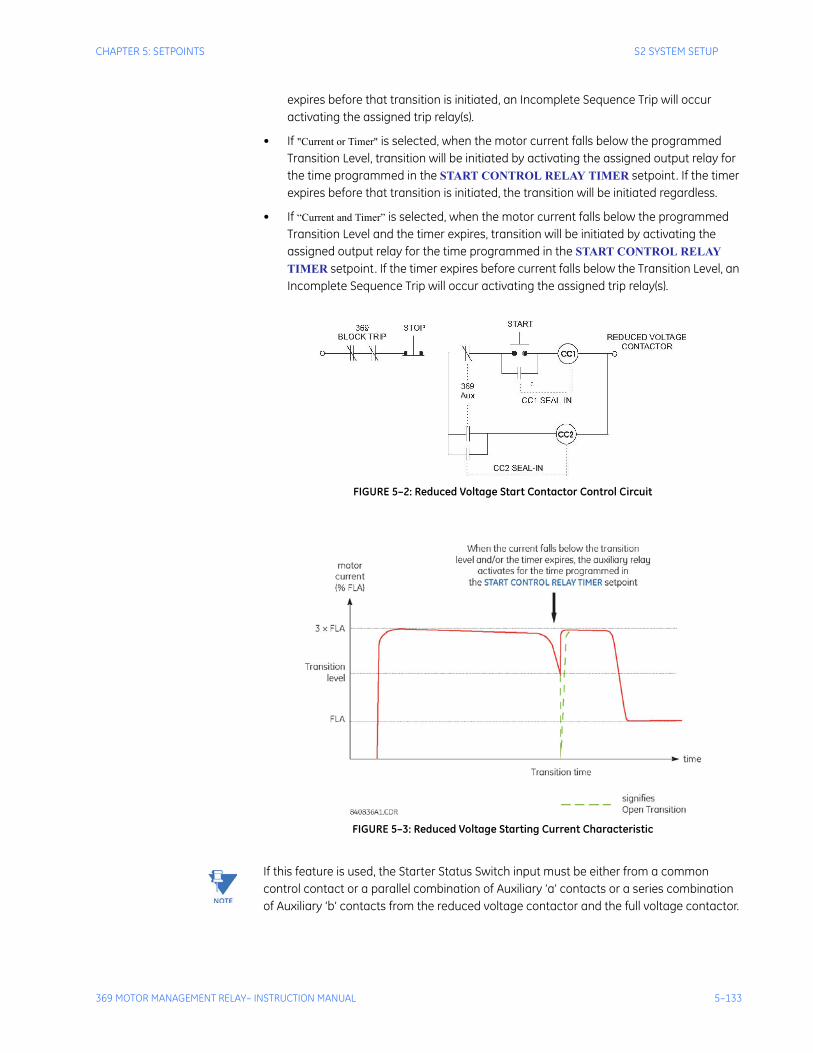
CHAPTER 5: SETPOINTS S2 SYSTEM SETUP
369 MOTOR MANAGEMENT RELAY– INSTRUCTION MANUAL 5–133
expires before that transition is initiated, an Incomplete Sequence Trip will occur activating the assigned trip relay(s).
• If "Current or Timer" is selected, when the motor current falls below the programmed Transition Level, transition will be initiated by activating the assigned output relay for the time programmed in the START CONTROL RELAY TIMER setpoint. If the timer expires before that transition is initiated, the transition will be initiated regardless.
• If “Current and Timer” is selected, when the motor current falls below the programmed Transition Level and the timer expires, transition will be initiated by activating the assigned output relay for the time programmed in the START CONTROL RELAY TIMER setpoint. If the timer expires before current falls below the Transition Level, an Incomplete Sequence Trip will occur activating the assigned trip relay(s).
FIGURE 5–2: Reduced Voltage Start Contactor Control Circuit
FIGURE 5–3: Reduced Voltage Starting Current Characteristic
Note If this feature is used, the Starter Status Switch input must be either from a common control contact or a parallel combination of Auxiliary ‘a’ contacts or a series combination of Auxiliary ‘b’ contacts from the reduced voltage contactor and the full voltage contactor.
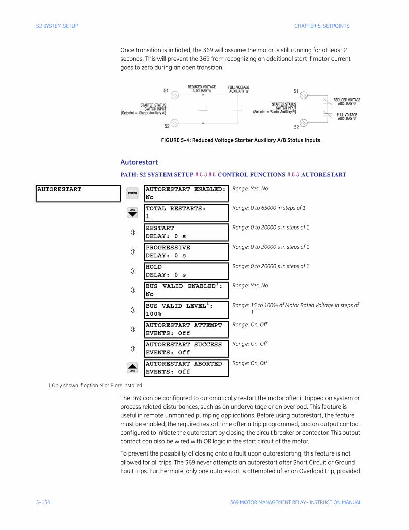
5–134 369 MOTOR MANAGEMENT RELAY– INSTRUCTION MANUAL
S2 SYSTEM SETUP CHAPTER 5: SETPOINTS
Once transition is initiated, the 369 will assume the motor is still running for at least 2 seconds. This will prevent the 369 from recognizing an additional start if motor current goes to zero during an open transition.
FIGURE 5–4: Reduced Voltage Starter Auxiliary A/B Status Inputs
Autorestart
PATH: S2 SYSTEM SETUP CONTROL FUNCTIONS AUTORESTART
The 369 can be configured to automatically restart the motor after it tripped on system or process related disturbances, such as an undervoltage or an overload. This feature is useful in remote unmanned pumping applications. Before using autorestart, the feature must be enabled, the required restart time after a trip programmed, and an output contact configured to initiate the autorestart by closing the circuit breaker or contactor. This output contact can also be wired with OR logic in the start circuit of the motor.
To prevent the possibility of closing onto a fault upon autorestarting, this feature is not allowed for all trips. The 369 never attempts an autorestart after Short Circuit or Ground Fault trips. Furthermore, only one autorestart is attempted after an Overload trip, provided
AUTORESTART AUTORESTART ENABLED:No
Range: Yes, No
TOTAL RESTARTS:1
Range: 0 to 65000 in steps of 1
RESTARTDELAY: 0 s
Range: 0 to 20000 s in steps of 1
PROGRESSIVEDELAY: 0 s
Range: 0 to 20000 s in steps of 1
HOLDDELAY: 0 s
Range: 0 to 20000 s in steps of 1
BUS VALID ENABLED1:No
Range: Yes, No
BUS VALID LEVEL1:100%
Range: 15 to 100% of Motor Rated Voltage in steps of 1
AUTORESTART ATTEMPTEVENTS: Off
Range: On, Off
AUTORESTART SUCCESSEVENTS: Off
Range: On, Off
AUTORESTART ABORTEDEVENTS: Off
Range: On, Off
1.Only shown if option M or B are installed

CHAPTER 5: SETPOINTS S2 SYSTEM SETUP
369 MOTOR MANAGEMENT RELAY– INSTRUCTION MANUAL 5–135
that Single Shot Restart is enabled, which allows a single restart attempt. The thermal capacity is cleared to prevent another overload trip during this start and if the 369 trips again (second time) on Overload the autorestarting is aborted. Any normal manual starting will probably be inhibited, (lockout time) allowing the motor to cool (thermal capacity to decay) before permitting another start.
The trip relay should reset before closing the auto-restart contact to allow the breaker or contactor to close. This is done by programming S2 SYSTEM SETUP OUPUT RELAY SETUP TRIP RESET MODE to “Remote Only” or “All Resets”. The close contact selection is enabled by setting the S2 SYSTEM SETUP CONTROL FUNCTIONS SERIAL COMMUNICATION CONTROL SERIAL COMMUNICATION CONTROL setpoint to “On” and selecting the desired output contact.
The 369 follows the logic shown in FIGURE 5–5: AUTORESTART LOGIC on page 5–136 to determine restart conditions. The total autorestart delay comprises the sum of three delays: Restart Delay, Progressive Delay, and Hold Delay. If any of these are not required, the autorestart delay can be set to zero.
Total Delay = Restart Delay + (auto-restarts number x Progressive Delay) + Hold Delay
The Restart Delay controls the basic auto-restart time and the timer start when the motor tripped. The Progressive Delay increases each consecutive auto-restart delay with its set amount. For example, assume that Restart Delay, Progressive Delay, and Hold Delay are 1, 3, and 0 seconds respectively. Therefore the fifth autorestart waiting time is:
1 sec. + 5th auto-restart × 3 sec. + 0 sec. = 1 sec. + 5 x 3 sec. = 16 sec.
The number of autorestarts is limited by the TOTAL RESTARTS setting to a maximum of 65000. Once this is exceeded, the 369 blocks further autorestarts until it is reset, either manually or remotely. This limit does not affect normal starting. Please note that 65000 autorestarts implies the motor has been tripped that many times and inspection or maintenance is probably due. The vendor's suggested number of circuit breaker or contactor operations before maintenance can affect this setting.
The Hold Delay sequentially staggers auto-restarts for multiple motors on a bus. For example, if four motors on a bus have settings of 60, 120, 180, and 240 seconds, respectively, it is advantageous, after a common fault that trips all four motors, to autorestart at 60 second intervals to minimize voltage sag and overloading
The presence of healthy bus voltage prior to the auto-restart can be verified by enabling the Bus Valid feature. The BUS VALID LEVEL setting is the voltage level below which autorestart is not to be attempted. The 369 checks the BUS VALID LEVEL just before the autorestart to allow the bus voltage to recover. This setpoint is only available if the Metering Option (M) or Backspin Option (B) is enabled.
Five different types of “Autorestart Aborted” events have been provided to help in troubleshooting. The following flowchart shows the logic flow of the Autorestart algorithm. Each type of Autorestart Aborted event and where it occurs within the logic flow is indicated in this diagram. For example, if an “Autorestart Aborted1” event is recorded in the event recorder, the logic diagram immediately indicates that the abort cause was the number of restart attempts being more than the MAXIMUM NUMBER OF RESTARTS setpoint.
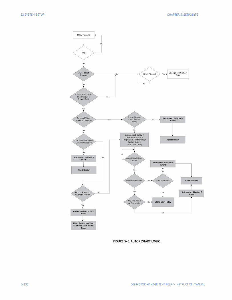
5–136 369 MOTOR MANAGEMENT RELAY– INSTRUCTION MANUAL
S2 SYSTEM SETUP CHAPTER 5: SETPOINTS
FIGURE 5–5: AUTORESTART LOGIC
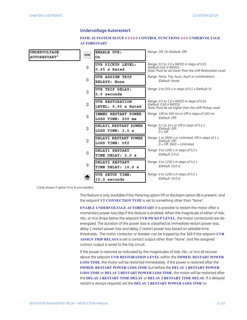
CHAPTER 5: SETPOINTS S2 SYSTEM SETUP
369 MOTOR MANAGEMENT RELAY– INSTRUCTION MANUAL 5–137
Undervoltage Autorestart
PATH: S2 SYSTEM SETUP CONTROL FUNCTIONS UNDERVOLTAGE AUTORESTART
This feature is only available if the Metering option (M) or Backspin option (B) is present, and the setpoint VT CONNECTION TYPE is set to something other than “None”.
ENABLE UNDERVOLTAGE AUTORESTART It is possible to restart the motor after a momentary power loss (dip) if this feature is enabled. When the magnitude of either of Vab, Vbc, or Vca drops below the setpoint UVR PICKUP LEVEL, the motor contactor(s) are de-energized. The duration of the power loss is classified as Immediate restart power loss, delay 1 restart power loss and delay 2 restart power loss based on settable time thresholds. The motor contactor or breaker can be tripped by the 369 if the setpoint UVR ASSIGN TRIP RELAYS is set a contact output other than “None”, and the assigned contact output is wired to the trip circuit.
If the power is restored as indicated by the magnitudes of Vab, Vbc, or Vca all recover above the setpoint UVR RESTORATION LEVEL within the IMMED. RESTART POWER LOSS TIME, the motor will be restarted immediately. If the power is restored after the IMMED. RESTART POWER LOSS TIME but before the DELAY 1 RESTART POWER LOSS TIME or DELAY 2 RESTART POWER LOSS TIME, the motor will be restarted after the DELAY 1 RESTART TIME DELAY or DELAY 2 RESTART TIME DELAY. If a delayed restart is always required, set the DELAY 2 RESTART POWER LOSS TIME to
UNDERVOLTAGE AUTORESTART1
ENABLE UVR:On
Range: Off, On (Default: Off)
UVR PICKUP LEVEL:0.65 x Rated
Range: 0.5 to 1.0 x RATED in steps of 0.01 (Default 0.65 X RATED)Note: Must be set lower than the UVR Restoration Level
UVR ASSIGN TRIP RELAYS: None
Range: None, Trip, Aux1, Aux2 or combinations(Default: None)
UVR TRIP DELAY: 0.0 seconds
Range: 0 to 255 s in steps of 0.1 s (Default: 0)
UVR RESTORATION LEVEL: 0.90 x Rated
Range: 0.5 to 1.0 x RATED in steps of 0.01(Default: 0.90 X RATED)Note: Must be set higher than the UVR Pickup Level
IMMED RESTART POWERLOSS TIME: 200 ms
Range: 100 to 500 ms or Off in steps of 100 ms(Default: Off)
DELAY1 RESTART POWER LOSS TIME: 2.0 s
Range: 0.1 to 10 s or Off in steps of 0.1 s(Default: Off)0 = Off
DELAY2 RESTART POWER LOSS TIME: Off
Range: 1 to 3600 s or Unlimited, Off in steps of 1 s(Default: Off)0 = Off, 3601 = Unlimited
DELAY1 RESTART TIME DELAY: 2.0 s
Range: 0 to 1200 s in steps of 0.2 s(Default: 2.0 s)
DELAY2 RESTART TIME DELAY: 10.0 s
Range: 0 to 1200 s in steps of 0.2 s(Default: 10.0 s)
UVR SETUP TIME: 10.0 seconds
Range: 0 to 1200 s in steps of 0.2 s(Default: 10.0 s)
1.Only shown if option M or B are installed

5–138 369 MOTOR MANAGEMENT RELAY– INSTRUCTION MANUAL
S2 SYSTEM SETUP CHAPTER 5: SETPOINTS
UNLIMITED. If another power loss occurs during the DELAY 1 RESTART TIME DELAY or DELAY 2 RESTART TIME DELAY, all the autorestart timers will be reset and the autorestart element will be re-initiated based on the latest power loss.
If this feature is used, the Spare Switch must be used as a Starter Status Switch input reflecting the state of the main contactor or breaker.
The trip relay should reset before closing the autorestart contact to allow the breaker or contactor to close. This is done by programming S2 SYSTEM SETUP - OUPUT RELAY SETUP - TRIP RESET MODE to “Remote Only” or “All Resets”. The element uses an output contact to initiate the autorestart by closing the circuit breaker or contactor. This output contact can be wired with OR logic in the start circuit of the motor. The close contact selection is enabled by setting the setpoint S2 SYSTEM SETUP - CONTROL FUNCTIONS - SERIAL COMMUNICATION CONTROL - SERIAL COMMUNICATION CONTROL to “On” and selecting the desired output contact for the setpoint ASSIGN START CONTROL RELAYS.
The difference between the undervoltage autorestart with the SYSTEM SETUP – CONTROL FUNCTIONS – AUTORESTART element: The undervoltage restart is blocked by any trip issued by 369 except undervoltage element, and if the undervoltage restart is enabled, the SYSTEM SETUP – CONTROL FUNCTIONS – AUTORESTART can't be activated by undervoltage element. It means that if the undervoltage autorestart is enabled, the undervoltage autorestart element covers no trip condition and under voltage trip condition, the SYSTEM SETUP – CONTROL FUNCTIONS – AUTORESTART covers all the trip condition except undervoltage condition.
UVR PICKUP LEVEL sets the motor voltage level below which the undervoltage autorestart element is triggered. Must be set lower than UVR RESTORATION LEVEL.
UVR ASSIGN TRIP RELAYS assign the trip relay to open the contactor or breaker when a power loss is detected and the duration is longer than the setpoint UVR TRIP DELAY. None disables the UVR trip output.
UVR TRIP DELAY sets the time delay to trip the breaker or contactor.
UVR RESTORATION LEVEL sets the motor voltage level above which the undervoltage autorestart element restarts. Must be set higher than UVR PICKUP LEVEL.
IMMED. RESTART POWER LOSS TIME sets the immediate autorestart power loss duration, which result in immediate restart. Off disables immediate restart.
DELAY 1 RESTART POWER LOSS TIME Off disables the delay 1 undervoltage autorestart.
DELAY 2 RESTART POWER LOSS TIME sets to UNLIMITED if a delayed restart is always required. Off disables the delay 2 undervoltage autorestart.
UVR SETUP TIME sets the amount of time the voltages must be healthy before a another immediate restart is to be attempted.
Note The Undervoltage Autorestart feature is intended for use in applications where the 369 is powered from an uninterruptible power supply, separate from the AC mains powering the motor. For applications where the 369 is supplied from the same AC mains as the motor, the timing specification for restarting the motor is ±9 seconds. Care must be taken when coordinating process start-up.
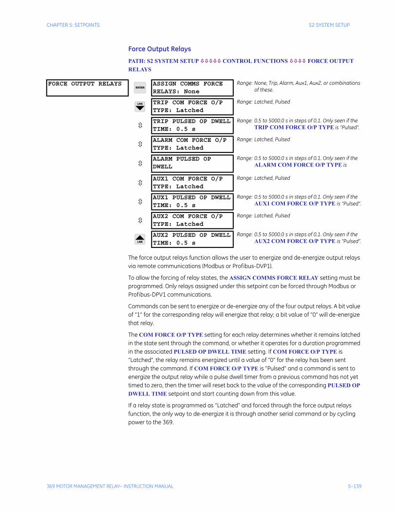
CHAPTER 5: SETPOINTS S2 SYSTEM SETUP
369 MOTOR MANAGEMENT RELAY– INSTRUCTION MANUAL 5–139
Force Output Relays
PATH: S2 SYSTEM SETUP CONTROL FUNCTIONS FORCE OUTPUT RELAYS
The force output relays function allows the user to energize and de-energize output relays via remote communications (Modbus or Profibus-DVP1).
To allow the forcing of relay states, the ASSIGN COMMS FORCE RELAY setting must be programmed. Only relays assigned under this setpoint can be forced through Modbus or Profibus-DPV1 communications.
Commands can be sent to energize or de-energize any of the four output relays. A bit value of “1” for the corresponding relay will energize that relay; a bit value of “0” will de-energize that relay.
The COM FORCE O/P TYPE setting for each relay determines whether it remains latched in the state sent through the command, or whether it operates for a duration programmed in the associated PULSED OP DWELL TIME setting. If COM FORCE O/P TYPE is “Latched”, the relay remains energized until a value of “0” for the relay has been sent through the command. If COM FORCE O/P TYPE is “Pulsed” and a command is sent to energize the output relay while a pulse dwell timer from a previous command has not yet timed to zero, then the timer will reset back to the value of the corresponding PULSED OP DWELL TIME setpoint and start counting down from this value.
If a relay state is programmed as “Latched” and forced through the force output relays function, the only way to de-energize it is through another serial command or by cycling power to the 369.
FORCE OUTPUT RELAYS ASSIGN COMMS FORCERELAYS: None
Range: None, Trip, Alarm, Aux1, Aux2, or combinations of these.
TRIP COM FORCE O/PTYPE: Latched
Range: Latched, Pulsed
TRIP PULSED OP DWELLTIME: 0.5 s
Range: 0.5 to 5000.0 s in steps of 0.1. Only seen if the TRIP COM FORCE O/P TYPE is “Pulsed”.
ALARM COM FORCE O/PTYPE: Latched
Range: Latched, Pulsed
ALARM PULSED OP DWELL
Range: 0.5 to 5000.0 s in steps of 0.1. Only seen if the ALARM COM FORCE O/P TYPE is
AUX1 COM FORCE O/PTYPE: Latched
Range: Latched, Pulsed
AUX1 PULSED OP DWELLTIME: 0.5 s
Range: 0.5 to 5000.0 s in steps of 0.1. Only seen if the AUX1 COM FORCE O/P TYPE is “Pulsed”.
AUX2 COM FORCE O/PTYPE: Latched
Range: Latched, Pulsed
AUX2 PULSED OP DWELLTIME: 0.5 s
Range: 0.5 to 5000.0 s in steps of 0.1. Only seen if the AUX2 COM FORCE O/P TYPE is “Pulsed”.

5–140 369 MOTOR MANAGEMENT RELAY– INSTRUCTION MANUAL
S2 SYSTEM SETUP CHAPTER 5: SETPOINTS
Note For safety reasons, if any of the relays in the S11 TESTING TEST OUTPUT RELAYS section are programmed to any value other than “Disabled” (i.e. energized or de-energized), then the force relays functionality through Modbus and Profibus-DPV1 will be disabled.
CHAPTER 5: SETPOINTS S3 OVERLOAD PROTECTION
369 MOTOR MANAGEMENT RELAY– INSTRUCTION MANUAL 5–141
5.4 S3 Overload Protection
5.4.1 DescriptionHeat is one of the principle enemies of motor life. When a motor is specified, the purchaser communicates to the manufacturer what the loading conditions, duty cycle, environment and pertinent information about the driven load such as starting torque. The manufacturer then provides a stock motor or builds a motor that should have a reasonable life under those conditions. The purchaser should request all safe stall, acceleration and running thermal limits for all motors they receive in order to effectively program the 369.
Motor thermal limits are dictated by the design of the stator and the rotor. Motors have three modes of operation: locked rotor or stall (rotor is not turning), acceleration (rotor is coming up to speed), and running (rotor turns at near synchronous speed). Heating occurs in the motor during each of these conditions in very distinct ways. Typically, during motor starting, locked rotor, and acceleration conditions, the motor is rotor limited. That is, the rotor approaches its thermal limit before the stator. Under locked rotor conditions, voltage is induced in the rotor at line frequency, 50 or 60 Hz. This voltage causes a current to flow in the rotor, also at line frequency, and the heat generated (I2R) is a function of the effective rotor resistance. At 50/60 Hz, the rotor cage reactance causes the current to flow at the outer edges of the rotor bars. The effective resistance of the rotor is therefore at a maximum during a locked rotor condition as is rotor heating. When the motor is running at rated speed, the voltage induced in the rotor is at a low frequency (approximately 1 Hz) and therefore, the effective resistance of the rotor is reduced quite dramatically. During running overloads, the motor thermal limit is typically dictated by stator parameters. Some special motors might be all stator or all rotor limited. During acceleration, the dynamic nature of the motor slip dictates that rotor impedance is also dynamic, and a third overload thermal limit characteristic is necessary.
Typical thermal limit curves are shown below. The motor starting characteristic is shown for a high inertia load at 80% voltage. If the motor started quicker, the distinct characteristics of the thermal limit curves would not be required and the running overload curve would be joined with locked rotor safe stall times to produce a single overload curve.
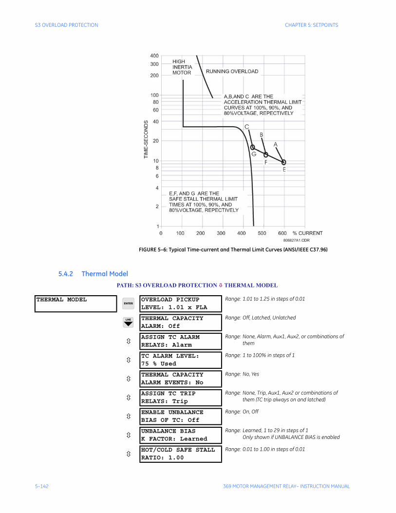
5–142 369 MOTOR MANAGEMENT RELAY– INSTRUCTION MANUAL
S3 OVERLOAD PROTECTION CHAPTER 5: SETPOINTS
FIGURE 5–6: Typical Time-current and Thermal Limit Curves (ANSI/IEEE C37.96)
5.4.2 Thermal ModelPATH: S3 OVERLOAD PROTECTION THERMAL MODEL
THERMAL MODEL OVERLOAD PICKUPLEVEL: 1.01 x FLA
Range: 1.01 to 1.25 in steps of 0.01
THERMAL CAPACITYALARM: Off
Range: Off, Latched, Unlatched
ASSIGN TC ALARMRELAYS: Alarm
Range: None, Alarm, Aux1, Aux2, or combinations of them
TC ALARM LEVEL:75 % Used
Range: 1 to 100% in steps of 1
THERMAL CAPACITYALARM EVENTS: No
Range: No, Yes
ASSIGN TC TRIPRELAYS: Trip
Range: None, Trip, Aux1, Aux2 or combinations of them (TC trip always on and latched)
ENABLE UNBALANCEBIAS OF TC: Off
Range: On, Off
UNBALANCE BIASK FACTOR: Learned
Range: Learned, 1 to 29 in steps of 1Only shown if UNBALANCE BIAS is enabled
HOT/COLD SAFE STALLRATIO: 1.00
Range: 0.01 to 1.00 in steps of 0.01
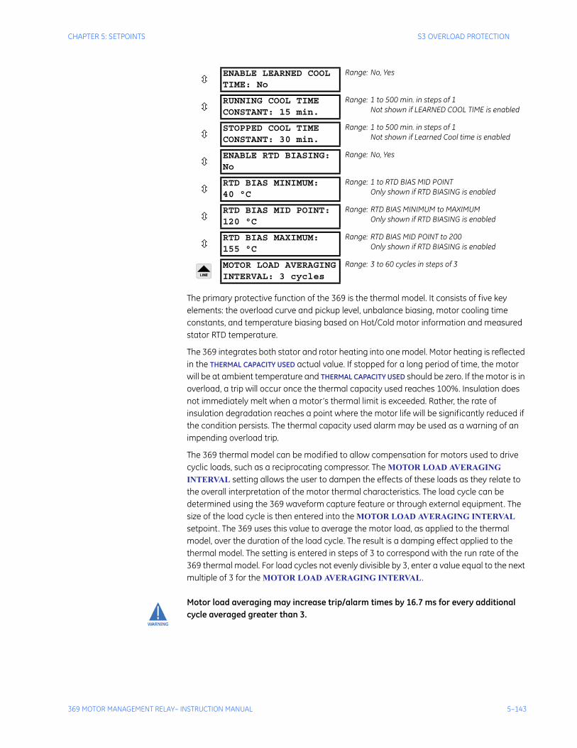
CHAPTER 5: SETPOINTS S3 OVERLOAD PROTECTION
369 MOTOR MANAGEMENT RELAY– INSTRUCTION MANUAL 5–143
The primary protective function of the 369 is the thermal model. It consists of five key elements: the overload curve and pickup level, unbalance biasing, motor cooling time constants, and temperature biasing based on Hot/Cold motor information and measured stator RTD temperature.
The 369 integrates both stator and rotor heating into one model. Motor heating is reflected in the THERMAL CAPACITY USED actual value. If stopped for a long period of time, the motor will be at ambient temperature and THERMAL CAPACITY USED should be zero. If the motor is in overload, a trip will occur once the thermal capacity used reaches 100%. Insulation does not immediately melt when a motor’s thermal limit is exceeded. Rather, the rate of insulation degradation reaches a point where the motor life will be significantly reduced if the condition persists. The thermal capacity used alarm may be used as a warning of an impending overload trip.
The 369 thermal model can be modified to allow compensation for motors used to drive cyclic loads, such as a reciprocating compressor. The MOTOR LOAD AVERAGING INTERVAL setting allows the user to dampen the effects of these loads as they relate to the overall interpretation of the motor thermal characteristics. The load cycle can be determined using the 369 waveform capture feature or through external equipment. The size of the load cycle is then entered into the MOTOR LOAD AVERAGING INTERVAL setpoint. The 369 uses this value to average the motor load, as applied to the thermal model, over the duration of the load cycle. The result is a damping effect applied to the thermal model. The setting is entered in steps of 3 to correspond with the run rate of the 369 thermal model. For load cycles not evenly divisible by 3, enter a value equal to the next multiple of 3 for the MOTOR LOAD AVERAGING INTERVAL.
Motor load averaging may increase trip/alarm times by 16.7 ms for every additional cycle averaged greater than 3.
ENABLE LEARNED COOLTIME: No
Range: No, Yes
RUNNING COOL TIMECONSTANT: 15 min.
Range: 1 to 500 min. in steps of 1Not shown if LEARNED COOL TIME is enabled
STOPPED COOL TIMECONSTANT: 30 min.
Range: 1 to 500 min. in steps of 1Not shown if Learned Cool time is enabled
ENABLE RTD BIASING:No
Range: No, Yes
RTD BIAS MINIMUM:40 °C
Range: 1 to RTD BIAS MID POINTOnly shown if RTD BIASING is enabled
RTD BIAS MID POINT:120 °C
Range: RTD BIAS MINIMUM to MAXIMUMOnly shown if RTD BIASING is enabled
RTD BIAS MAXIMUM:155 °C
Range: RTD BIAS MID POINT to 200Only shown if RTD BIASING is enabled
MOTOR LOAD AVERAGINGINTERVAL: 3 cycles
Range: 3 to 60 cycles in steps of 3
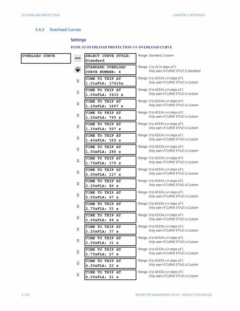
5–144 369 MOTOR MANAGEMENT RELAY– INSTRUCTION MANUAL
S3 OVERLOAD PROTECTION CHAPTER 5: SETPOINTS
5.4.3 Overload Curves
Settings
PATH: S3 OVERLOAD PROTECTION OVERLOAD CURVE
OVERLOAD CURVE SELECT CURVE STYLE:Standard
Range: Standard, Custom
STANDARD OVERLOADCURVE NUMBER: 4
Range: 1 to 15 in steps of 1Only seen if CURVE STYLE is Standard
TIME TO TRIP AT1.01xFLA: 17415s
Range: 0 to 65534 s in steps of 1Only seen if CURVE STYLE is Custom
TIME TO TRIP AT1.05xFLA: 3415 s
Range: 0 to 65534 s in steps of 1Only seen if CURVE STYLE is Custom
TIME TO TRIP AT1.10xFLA: 1667 s
Range: 0 to 65534 s in steps of 1Only seen if CURVE STYLE is Custom
TIME TO TRIP AT1.20xFLA: 795 s
Range: 0 to 65534 s in steps of 1Only seen if CURVE STYLE is Custom
TIME TO TRIP AT1.30xFLA: 507 s
Range: 0 to 65534 s in steps of 1Only seen if CURVE STYLE is Custom
TIME TO TRIP AT1.40xFLA: 365 s
Range: 0 to 65534 s in steps of 1Only seen if CURVE STYLE is Custom
TIME TO TRIP AT1.50xFLA: 280 s
Range: 0 to 65534 s in steps of 1Only seen if CURVE STYLE is Custom
TIME TO TRIP AT1.75xFLA: 170 s
Range: 0 to 65534 s in steps of 1Only seen if CURVE STYLE is Custom
TIME TO TRIP AT2.00xFLA: 117 s
Range: 0 to 65534 s in steps of 1Only seen if CURVE STYLE is Custom
TIME TO TRIP AT2.25xFLA: 86 s
Range: 0 to 65534 s in steps of 1Only seen if CURVE STYLE is Custom
TIME TO TRIP AT2.50xFLA: 67 s
Range: 0 to 65534 s in steps of 1Only seen if CURVE STYLE is Custom
TIME TO TRIP AT2.75xFLA: 53 s
Range: 0 to 65534 s in steps of 1Only seen if CURVE STYLE is Custom
TIME TO TRIP AT3.00xFLA: 44 s
Range: 0 to 65534 s in steps of 1Only seen if CURVE STYLE is Custom
TIME TO TRIP AT3.25xFLA: 37 s
Range: 0 to 65534 s in steps of 1Only seen if CURVE STYLE is Custom
TIME TO TRIP AT3.50xFLA: 31 s
Range: 0 to 65534 s in steps of 1Only seen if CURVE STYLE is Custom
TIME TO TRIP AT3.75xFLA: 27 s
Range: 0 to 65534 s in steps of 1Only seen if CURVE STYLE is Custom
TIME TO TRIP AT4.00xFLA: 23 s
Range: 0 to 65534 s in steps of 1Only seen if CURVE STYLE is Custom
TIME TO TRIP AT4.25xFLA: 21 s
Range: 0 to 65534 s in steps of 1Only seen if CURVE STYLE is Custom
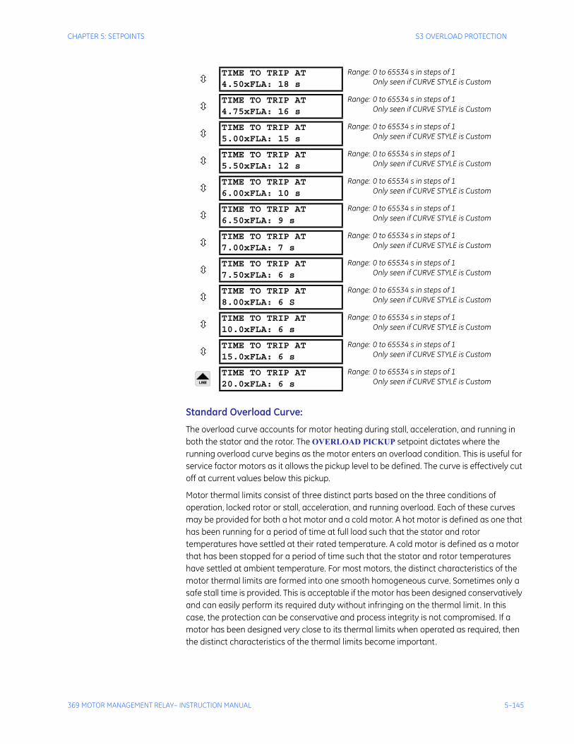
CHAPTER 5: SETPOINTS S3 OVERLOAD PROTECTION
369 MOTOR MANAGEMENT RELAY– INSTRUCTION MANUAL 5–145
Standard Overload Curve:
The overload curve accounts for motor heating during stall, acceleration, and running in both the stator and the rotor. The OVERLOAD PICKUP setpoint dictates where the running overload curve begins as the motor enters an overload condition. This is useful for service factor motors as it allows the pickup level to be defined. The curve is effectively cut off at current values below this pickup.
Motor thermal limits consist of three distinct parts based on the three conditions of operation, locked rotor or stall, acceleration, and running overload. Each of these curves may be provided for both a hot motor and a cold motor. A hot motor is defined as one that has been running for a period of time at full load such that the stator and rotor temperatures have settled at their rated temperature. A cold motor is defined as a motor that has been stopped for a period of time such that the stator and rotor temperatures have settled at ambient temperature. For most motors, the distinct characteristics of the motor thermal limits are formed into one smooth homogeneous curve. Sometimes only a safe stall time is provided. This is acceptable if the motor has been designed conservatively and can easily perform its required duty without infringing on the thermal limit. In this case, the protection can be conservative and process integrity is not compromised. If a motor has been designed very close to its thermal limits when operated as required, then the distinct characteristics of the thermal limits become important.
TIME TO TRIP AT4.50xFLA: 18 s
Range: 0 to 65534 s in steps of 1Only seen if CURVE STYLE is Custom
TIME TO TRIP AT4.75xFLA: 16 s
Range: 0 to 65534 s in steps of 1Only seen if CURVE STYLE is Custom
TIME TO TRIP AT5.00xFLA: 15 s
Range: 0 to 65534 s in steps of 1Only seen if CURVE STYLE is Custom
TIME TO TRIP AT5.50xFLA: 12 s
Range: 0 to 65534 s in steps of 1Only seen if CURVE STYLE is Custom
TIME TO TRIP AT6.00xFLA: 10 s
Range: 0 to 65534 s in steps of 1Only seen if CURVE STYLE is Custom
TIME TO TRIP AT6.50xFLA: 9 s
Range: 0 to 65534 s in steps of 1Only seen if CURVE STYLE is Custom
TIME TO TRIP AT7.00xFLA: 7 s
Range: 0 to 65534 s in steps of 1Only seen if CURVE STYLE is Custom
TIME TO TRIP AT7.50xFLA: 6 s
Range: 0 to 65534 s in steps of 1Only seen if CURVE STYLE is Custom
TIME TO TRIP AT8.00xFLA: 6 S
Range: 0 to 65534 s in steps of 1Only seen if CURVE STYLE is Custom
TIME TO TRIP AT10.0xFLA: 6 s
Range: 0 to 65534 s in steps of 1Only seen if CURVE STYLE is Custom
TIME TO TRIP AT15.0xFLA: 6 s
Range: 0 to 65534 s in steps of 1Only seen if CURVE STYLE is Custom
TIME TO TRIP AT20.0xFLA: 6 s
Range: 0 to 65534 s in steps of 1Only seen if CURVE STYLE is Custom
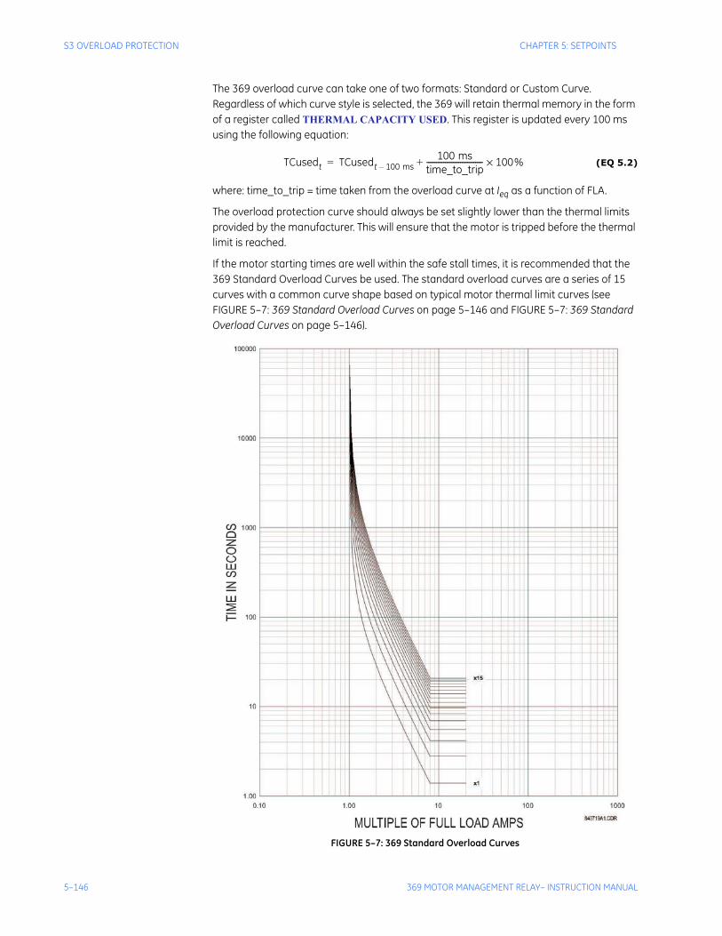
5–146 369 MOTOR MANAGEMENT RELAY– INSTRUCTION MANUAL
S3 OVERLOAD PROTECTION CHAPTER 5: SETPOINTS
The 369 overload curve can take one of two formats: Standard or Custom Curve. Regardless of which curve style is selected, the 369 will retain thermal memory in the form of a register called THERMAL CAPACITY USED. This register is updated every 100 ms using the following equation:
(EQ 5.2)
where: time_to_trip = time taken from the overload curve at Ieq as a function of FLA.
The overload protection curve should always be set slightly lower than the thermal limits provided by the manufacturer. This will ensure that the motor is tripped before the thermal limit is reached.
If the motor starting times are well within the safe stall times, it is recommended that the 369 Standard Overload Curves be used. The standard overload curves are a series of 15 curves with a common curve shape based on typical motor thermal limit curves (see FIGURE 5–7: 369 Standard Overload Curves on page 5–146 and FIGURE 5–7: 369 Standard Overload Curves on page 5–146).
FIGURE 5–7: 369 Standard Overload Curves
TCusedt TCusedt 100 ms–100 ms
time_to_trip------------------------------ 100%×+=
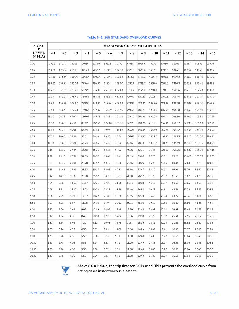
CHAPTER 5: SETPOINTS S3 OVERLOAD PROTECTION
369 MOTOR MANAGEMENT RELAY– INSTRUCTION MANUAL 5–147
Note Above 8.0 x Pickup, the trip time for 8.0 is used. This prevents the overload curve from acting as an instantaneous element.
Table 5–1: 369 STANDARD OVERLOAD CURVES
PICKUP
LEVEL(× FLA)
STANDARD CURVE MULTIPLIERS
× 1 × 2 × 3 × 4 × 5 × 6 × 7 × 8 × 9 × 10 × 11 × 12 × 13 × 14 × 15
1.01 4353.6 8707.2 13061 17414 21768 26122 30475 34829 39183 43536 47890 52243 56597 60951 65304
1.05 853.71 1707.4 2561.1 3414.9 4268.6 5122.3 5976.0 6829.7 7683.4 8537.1 9390.8 10245 11098 11952 12806
1.10 416.68 833.36 1250.0 1666.7 2083.4 2500.1 2916.8 3333.5 3750.1 4166.8 4583.5 5000.2 5416.9 5833.6 6250.2
1.20 198.86 397.72 596.58 795.44 994.30 1193.2 1392.0 1590.9 1789.7 1988.6 2187.5 2386.3 2585.2 2784.1 2982.9
1.30 126.80 253.61 380.41 507.22 634.02 760.82 887.63 1014.4 1141.2 1268.0 1394.8 1521.6 1648.5 1775.3 1902.1
1.40 91.14 182.27 273.41 364.55 455.68 546.82 637.96 729.09 820.23 911.37 1002.5 1093.6 1184.8 1275.9 1367.0
1.50 69.99 139.98 209.97 279.96 349.95 419.94 489.93 559.92 629.91 699.90 769.89 839.88 909.87 979.86 1049.9
1.75 42.41 84.83 127.24 169.66 212.07 254.49 296.90 339.32 381.73 392.15 466.56 508.98 551.39 593.81 636.22
2.00 29.16 58.32 87.47 116.63 145.79 174.95 204.11 233.26 262.42 291.58 320.74 349.90 379.05 408.21 437.37
2.25 21.53 43.06 64.59 86.12 107.65 129.18 150.72 172.25 193.78 215.31 236.84 258.37 279.90 301.43 322.96
2.50 16.66 33.32 49.98 66.64 83.30 99.96 116.62 133.28 149.94 166.60 183.26 199.92 216.58 233.24 249.90
2.75 13.33 26.65 39.98 53.31 66.64 79.96 93.29 106.62 119.95 133.27 146.60 159.93 173.25 186.58 199.91
3.00 10.93 21.86 32.80 43.73 54.66 65.59 76.52 87.46 98.39 109.32 120.25 131.19 142.12 153.05 163.98
3.25 9.15 18.29 27.44 36.58 45.73 54.87 64.02 73.16 82.31 91.46 100.60 109.75 118.89 128.04 137.18
3.50 7.77 15.55 23.32 31.09 38.87 46.64 54.41 62.19 69.96 77.73 85.51 93.28 101.05 108.83 116.60
3.75 6.69 13.39 20.08 26.78 33.47 40.17 46.86 53.56 60.25 66.95 73.64 80.34 87.03 93.73 100.42
4.00 5.83 11.66 17.49 23.32 29.15 34.98 40.81 46.64 52.47 58.30 64.13 69.96 75.79 81.62 87.45
4.25 5.12 10.25 15.37 20.50 25.62 30.75 35.87 41.00 46.12 51.25 56.37 61.50 66.62 71.75 76.87
4.50 4.54 9.08 13.63 18.17 22.71 27.25 31.80 36.34 40.88 45.42 49.97 54.51 59.05 63.59 68.14
4.75 4.06 8.11 12.17 16.22 20.28 24.33 28.39 32.44 36.50 40.55 44.61 48.66 52.72 56.77 60.83
5.00 3.64 7.29 10.93 14.57 18.22 21.86 25.50 29.15 32.79 36.43 40.08 43.72 47.36 51.01 54.65
5.50 2.99 5.98 8.97 11.96 14.95 17.94 20.93 23.91 26.90 29.89 32.88 35.87 38.86 41.85 44.84
6.00 2.50 5.00 7.49 9.99 12.49 14.99 17.49 19.99 22.48 24.98 27.48 29.98 32.48 34.97 37.47
6.50 2.12 4.24 6.36 8.48 10.60 12.72 14.84 16.96 19.08 21.20 23.32 25.44 27.55 29.67 31.79
7.00 1.82 3.64 5.46 7.29 9.11 10.93 12.75 14.57 16.39 18.21 20.04 21.86 23.68 25.50 27.32
7.50 1.58 3.16 4.75 6.33 7.91 9.49 11.08 12.66 14.24 15.82 17.41 18.99 20.57 22.15 23.74
8.00 1.39 2.78 4.16 5.55 6.94 8.33 9.71 11.10 12.49 13.88 15.27 16.65 18.04 19.43 20.82
10.00 1.39 2.78 4.16 5.55 6.94 8.33 9.71 11.10 12.49 13.88 15.27 16.65 18.04 19.43 20.82
15.00 1.39 2.78 4.16 5.55 6.94 8.33 9.71 11.10 12.49 13.88 15.27 16.65 18.04 19.43 20.82
20.00 1.39 2.78 4.16 5.55 6.94 8.33 9.71 11.10 12.49 13.88 15.27 16.65 18.04 19.43 20.82

5–148 369 MOTOR MANAGEMENT RELAY– INSTRUCTION MANUAL
S3 OVERLOAD PROTECTION CHAPTER 5: SETPOINTS
The Standard Overload Curves equation is:
(EQ 5.3)
Custom Overload Curve:
If the motor starting current begins to infringe on the thermal damage curves, it may be necessary to use a custom curve to ensure successful starting without compromising motor protection. Furthermore, the characteristics of the starting thermal damage curve (locked rotor and acceleration) and the running thermal damage curves may not fit together very smoothly. In this instance, it may be necessary to use a custom curve to tailor protection to the motor thermal limits so the motor may be started successfully and used to its full potential without compromising protection. The distinct parts of the thermal limit curves now become more critical. For these conditions, it is recommended that the 369 custom curve thermal model be used. The custom overload curve of the 369 allows the user to program their own curve by entering trip times for 30 pre-determined current levels. The 369 smooths the areas between these points to make the protection curve.
It can be seen below that if the running overload thermal limit curve were smoothed into one curve with the locked rotor overload curve, the motor could not start at 80% line voltage. A custom curve is required.
time_to_tripcurve_multiplier 2.2116623×
0.02530337 pickup 1–( )2× 0.05054758 pickup 1–( )×+-----------------------------------------------------------------------------------------------------------------------------------------------=
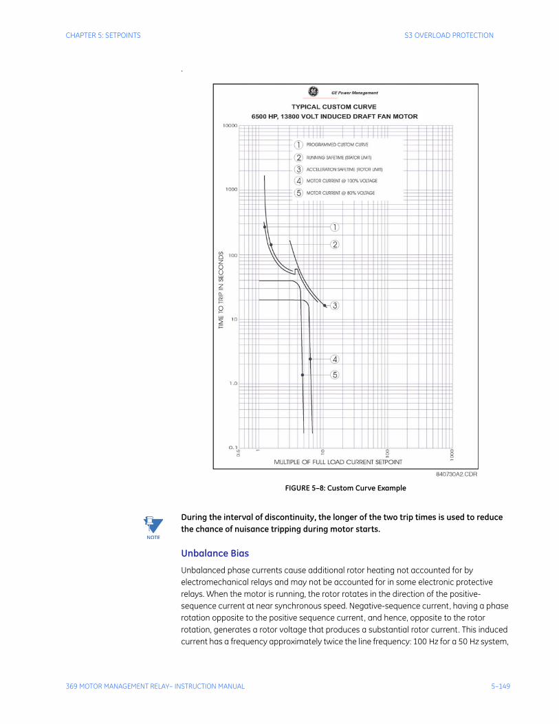
CHAPTER 5: SETPOINTS S3 OVERLOAD PROTECTION
369 MOTOR MANAGEMENT RELAY– INSTRUCTION MANUAL 5–149
.
FIGURE 5–8: Custom Curve Example
Note During the interval of discontinuity, the longer of the two trip times is used to reduce the chance of nuisance tripping during motor starts.
Unbalance Bias
Unbalanced phase currents cause additional rotor heating not accounted for by electromechanical relays and may not be accounted for in some electronic protective relays. When the motor is running, the rotor rotates in the direction of the positive-sequence current at near synchronous speed. Negative-sequence current, having a phase rotation opposite to the positive sequence current, and hence, opposite to the rotor rotation, generates a rotor voltage that produces a substantial rotor current. This induced current has a frequency approximately twice the line frequency: 100 Hz for a 50 Hz system,
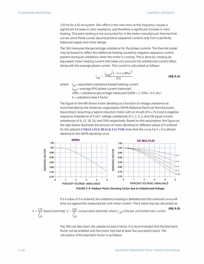
5–150 369 MOTOR MANAGEMENT RELAY– INSTRUCTION MANUAL
S3 OVERLOAD PROTECTION CHAPTER 5: SETPOINTS
120 Hz for a 60 Hz system. Skin effect in the rotor bars at this frequency causes a significant increase in rotor resistance, and therefore a significant increase in rotor heating. This extra heating is not accounted for in the motor manufacturer thermal limit curves, since these curves assume positive-sequence currents only from a perfectly balanced supply and motor design.
The 369 measures the percentage unbalance for the phase currents. The thermal model may be biased to reflect the additional heating caused by negative-sequence current, present during an unbalance when the motor is running. This is done by creating an equivalent motor heating current that takes into account the unbalanced current effect along with the average phase current. This current is calculated as follows:
(EQ 5.4)
where: Ieq = equivalent unbalance biased heating currentIavg = average RMS phase current measuredUB% = unbalance percentage measured (100% = 1, 50% = 0.5, etc.)k = unbalance bias k factor
The figure on the left shows motor derating as a function of voltage unbalance as recommended by the American organization NEMA (National Electrical Manufacturers Association). Assuming a typical induction motor with an inrush of 6 × FLA and a negative sequence impedance of 0.167, voltage unbalances of 1, 2, 3, 4, and 5% equal current unbalances of 6, 12, 18, 24, and 30% respectively. Based on this assumption, the figure on the right below illustrates the amount of motor derating for different values of k entered for the setpoint UNBALANCE BIAS K FACTOR. Note that the curve for k = 8 is almost identical to the NEMA derating curve.
FIGURE 5–9: Medium Motor Derating Factor due to Unbalanced Voltage
If a k value of 0 is entered, the unbalance biasing is defeated and the overload curve will time out against the measured per unit motor current. The k value may be calculated as:
(EQ 5.5)
The 369 can also learn the unbalance bias k factor. It is recommended that the learned k factor not be enabled until the motor has had at least five successful starts. The calculation of the learned k factor is as follows:
Ieq
Iavg 1 k UB%( )× 2+
FLA-------------------------------------------------------=
NEMA GE MULTILIN
k 175
ILR2
---------= (typical estimate); k 230
ILR2
---------= (conservative estimate), where ILR is the per unit locked rotor current
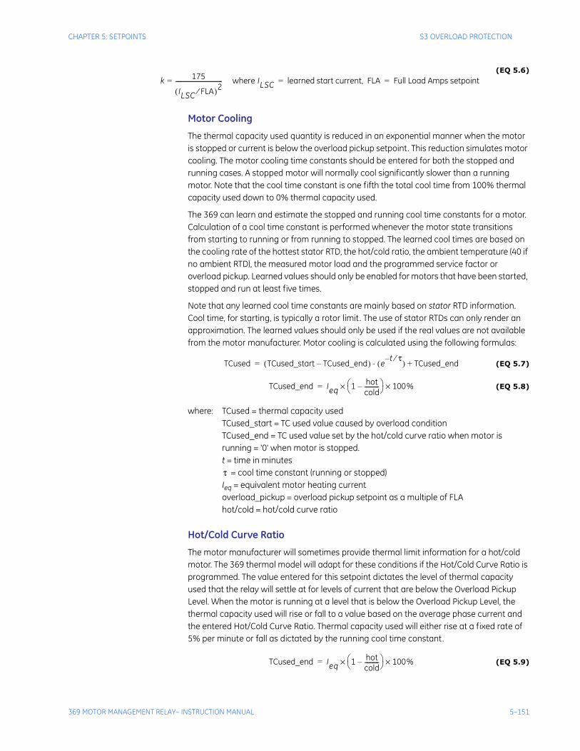
CHAPTER 5: SETPOINTS S3 OVERLOAD PROTECTION
369 MOTOR MANAGEMENT RELAY– INSTRUCTION MANUAL 5–151
(EQ 5.6)
Motor Cooling
The thermal capacity used quantity is reduced in an exponential manner when the motor is stopped or current is below the overload pickup setpoint. This reduction simulates motor cooling. The motor cooling time constants should be entered for both the stopped and running cases. A stopped motor will normally cool significantly slower than a running motor. Note that the cool time constant is one fifth the total cool time from 100% thermal capacity used down to 0% thermal capacity used.
The 369 can learn and estimate the stopped and running cool time constants for a motor. Calculation of a cool time constant is performed whenever the motor state transitions from starting to running or from running to stopped. The learned cool times are based on the cooling rate of the hottest stator RTD, the hot/cold ratio, the ambient temperature (40 if no ambient RTD), the measured motor load and the programmed service factor or overload pickup. Learned values should only be enabled for motors that have been started, stopped and run at least five times.
Note that any learned cool time constants are mainly based on stator RTD information. Cool time, for starting, is typically a rotor limit. The use of stator RTDs can only render an approximation. The learned values should only be used if the real values are not available from the motor manufacturer. Motor cooling is calculated using the following formulas:
(EQ 5.7)
(EQ 5.8)
where: TCused = thermal capacity usedTCused_start = TC used value caused by overload conditionTCused_end = TC used value set by the hot/cold curve ratio when motor is running = '0' when motor is stopped.t = time in minutes
= cool time constant (running or stopped)Ieq = equivalent motor heating currentoverload_pickup = overload pickup setpoint as a multiple of FLAhot/cold = hot/cold curve ratio
Hot/Cold Curve Ratio
The motor manufacturer will sometimes provide thermal limit information for a hot/cold motor. The 369 thermal model will adapt for these conditions if the Hot/Cold Curve Ratio is programmed. The value entered for this setpoint dictates the level of thermal capacity used that the relay will settle at for levels of current that are below the Overload Pickup Level. When the motor is running at a level that is below the Overload Pickup Level, the thermal capacity used will rise or fall to a value based on the average phase current and the entered Hot/Cold Curve Ratio. Thermal capacity used will either rise at a fixed rate of 5% per minute or fall as dictated by the running cool time constant.
(EQ 5.9)
k 175
ILSC FLA⁄( )2---------------------------------= where ILSC learned start current, FLA Full Load Amps setpoint= =
TCused TCused_start TCused_end–( ) et– τ⁄( )⋅ TCused_end+=
TCused_end Ieq 1 hotcold----------–⎝ ⎠
⎛ ⎞ 100%××=
τ
TCused_end Ieq 1 hotcold----------–⎝ ⎠
⎛ ⎞ 100%××=
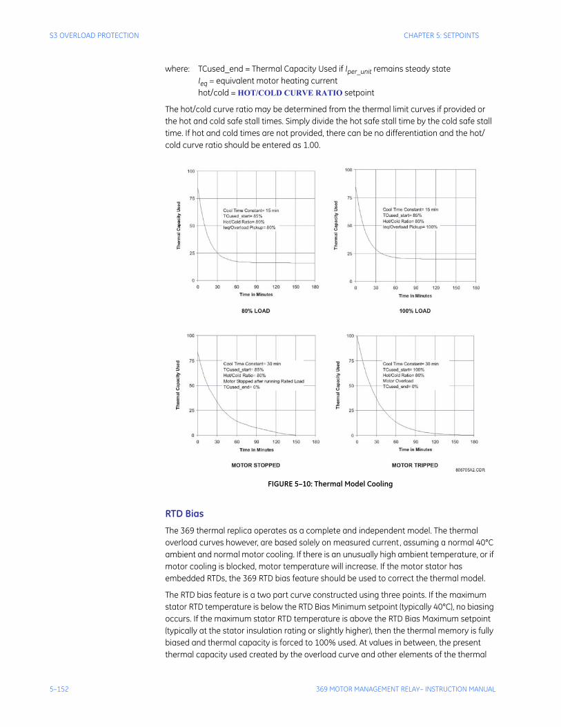
5–152 369 MOTOR MANAGEMENT RELAY– INSTRUCTION MANUAL
S3 OVERLOAD PROTECTION CHAPTER 5: SETPOINTS
where: TCused_end = Thermal Capacity Used if Iper_unit remains steady stateIeq = equivalent motor heating currenthot/cold = HOT/COLD CURVE RATIO setpoint
The hot/cold curve ratio may be determined from the thermal limit curves if provided or the hot and cold safe stall times. Simply divide the hot safe stall time by the cold safe stall time. If hot and cold times are not provided, there can be no differentiation and the hot/cold curve ratio should be entered as 1.00.
FIGURE 5–10: Thermal Model Cooling
RTD Bias
The 369 thermal replica operates as a complete and independent model. The thermal overload curves however, are based solely on measured current, assuming a normal 40°C ambient and normal motor cooling. If there is an unusually high ambient temperature, or if motor cooling is blocked, motor temperature will increase. If the motor stator has embedded RTDs, the 369 RTD bias feature should be used to correct the thermal model.
The RTD bias feature is a two part curve constructed using three points. If the maximum stator RTD temperature is below the RTD Bias Minimum setpoint (typically 40°C), no biasing occurs. If the maximum stator RTD temperature is above the RTD Bias Maximum setpoint (typically at the stator insulation rating or slightly higher), then the thermal memory is fully biased and thermal capacity is forced to 100% used. At values in between, the present thermal capacity used created by the overload curve and other elements of the thermal
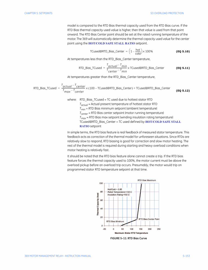
CHAPTER 5: SETPOINTS S3 OVERLOAD PROTECTION
369 MOTOR MANAGEMENT RELAY– INSTRUCTION MANUAL 5–153
model is compared to the RTD Bias thermal capacity used from the RTD Bias curve. If the RTD Bias thermal capacity used value is higher, then that value is used from that point onward. The RTD Bias Center point should be set at the rated running temperature of the motor. The 369 will automatically determine the thermal capacity used value for the center point using the HOT/COLD SAFE STALL RATIO setpoint.
(EQ 5.10)
At temperatures less than the RTD_Bias_Center temperature,
(EQ 5.11)
At temperatures greater than the RTD_Bias_Center temperature,
(EQ 5.12)
where: RTD_Bias_TCused = TC used due to hottest stator RTDTactual = Actual present temperature of hottest stator RTDTmin = RTD Bias minimum setpoint (ambient temperature)Tcenter = RTD Bias center setpoint (motor running temperature)Tmax = RTD Bias max setpoint (winding insulation rating temperature)TCused@RTD_Bias_Center = TC used defined by HOT/COLD SAFE STALL RATIO setpoint
In simple terms, the RTD bias feature is real feedback of measured stator temperature. This feedback acts as correction of the thermal model for unforeseen situations. Since RTDs are relatively slow to respond, RTD biasing is good for correction and slow motor heating. The rest of the thermal model is required during starting and heavy overload conditions when motor heating is relatively fast.
It should be noted that the RTD bias feature alone cannot create a trip. If the RTD bias feature forces the thermal capacity used to 100%, the motor current must be above the overload pickup before an overload trip occurs. Presumably, the motor would trip on programmed stator RTD temperature setpoint at that time.
FIGURE 5–11: RTD Bias Curve
TCused@RTD_Bias_Center 1 hotcold----------–⎝ ⎠
⎛ ⎞ 100%×=
RTD_Bias_TCusedTactual Tmin–
Tcenter Tmin–--------------------------------------- TCused@RTD_Bias_Center×=
RTD_Bias_TCusedTactual Tcenter–
Tmax Tcenter–---------------------------------------------- 100 TCused@RTD_Bias_Center–( )× TCused@RTD_Bias_Center+=
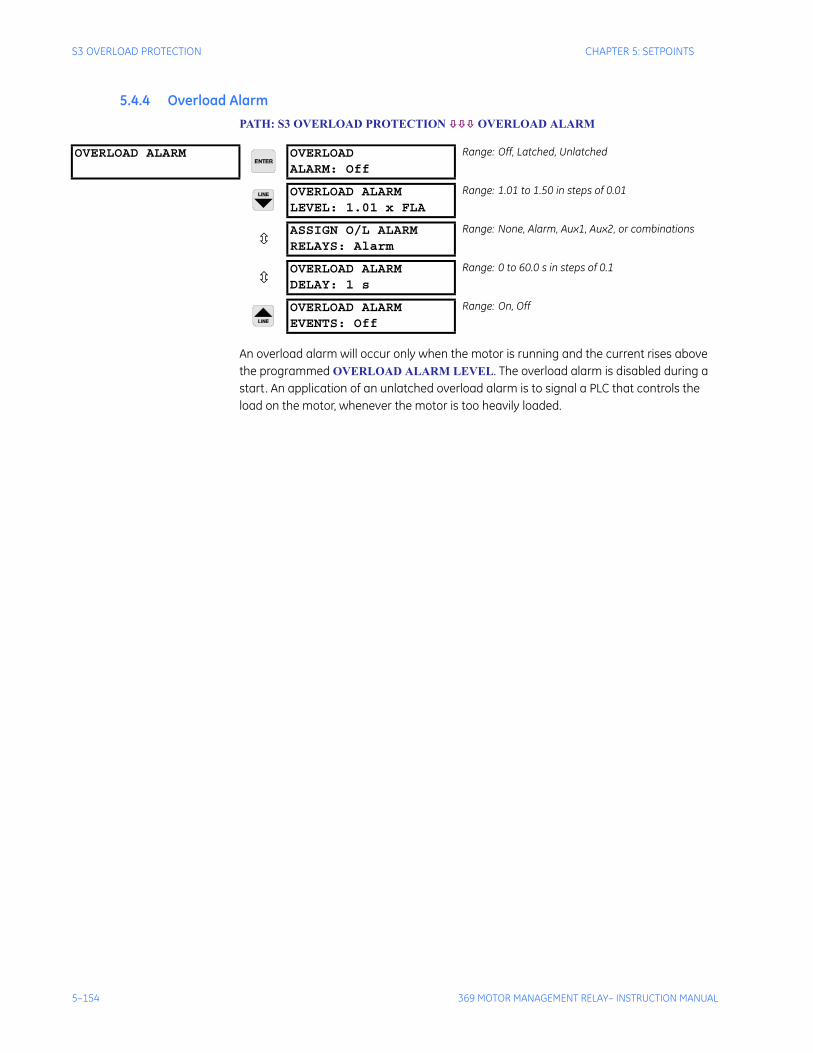
5–154 369 MOTOR MANAGEMENT RELAY– INSTRUCTION MANUAL
S3 OVERLOAD PROTECTION CHAPTER 5: SETPOINTS
5.4.4 Overload AlarmPATH: S3 OVERLOAD PROTECTION OVERLOAD ALARM
An overload alarm will occur only when the motor is running and the current rises above the programmed OVERLOAD ALARM LEVEL. The overload alarm is disabled during a start. An application of an unlatched overload alarm is to signal a PLC that controls the load on the motor, whenever the motor is too heavily loaded.
OVERLOAD ALARM OVERLOADALARM: Off
Range: Off, Latched, Unlatched
OVERLOAD ALARMLEVEL: 1.01 x FLA
Range: 1.01 to 1.50 in steps of 0.01
ASSIGN O/L ALARMRELAYS: Alarm
Range: None, Alarm, Aux1, Aux2, or combinations
OVERLOAD ALARMDELAY: 1 s
Range: 0 to 60.0 s in steps of 0.1
OVERLOAD ALARMEVENTS: Off
Range: On, Off
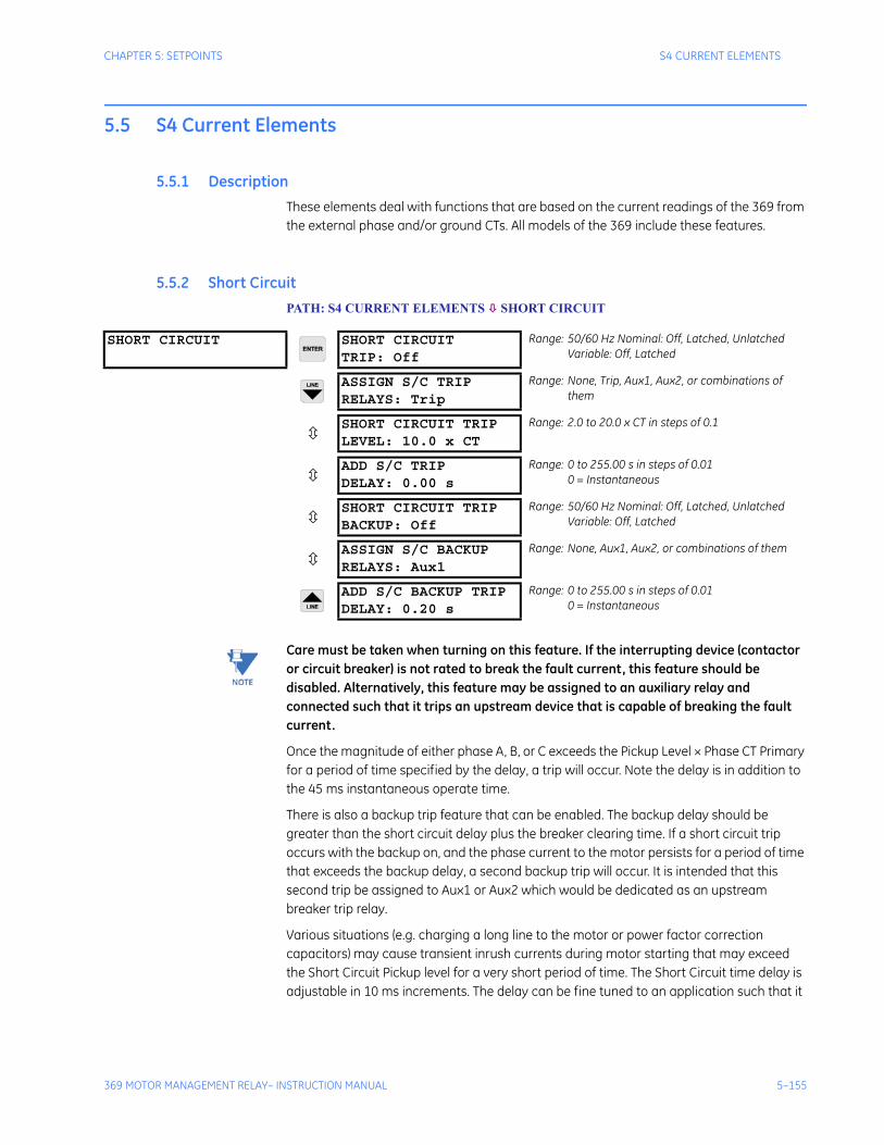
CHAPTER 5: SETPOINTS S4 CURRENT ELEMENTS
369 MOTOR MANAGEMENT RELAY– INSTRUCTION MANUAL 5–155
5.5 S4 Current Elements
5.5.1 DescriptionThese elements deal with functions that are based on the current readings of the 369 from the external phase and/or ground CTs. All models of the 369 include these features.
5.5.2 Short CircuitPATH: S4 CURRENT ELEMENTS SHORT CIRCUIT
Note Care must be taken when turning on this feature. If the interrupting device (contactor or circuit breaker) is not rated to break the fault current, this feature should be disabled. Alternatively, this feature may be assigned to an auxiliary relay and connected such that it trips an upstream device that is capable of breaking the fault current.
Once the magnitude of either phase A, B, or C exceeds the Pickup Level × Phase CT Primary for a period of time specified by the delay, a trip will occur. Note the delay is in addition to the 45 ms instantaneous operate time.
There is also a backup trip feature that can be enabled. The backup delay should be greater than the short circuit delay plus the breaker clearing time. If a short circuit trip occurs with the backup on, and the phase current to the motor persists for a period of time that exceeds the backup delay, a second backup trip will occur. It is intended that this second trip be assigned to Aux1 or Aux2 which would be dedicated as an upstream breaker trip relay.
Various situations (e.g. charging a long line to the motor or power factor correction capacitors) may cause transient inrush currents during motor starting that may exceed the Short Circuit Pickup level for a very short period of time. The Short Circuit time delay is adjustable in 10 ms increments. The delay can be fine tuned to an application such that it
SHORT CIRCUIT SHORT CIRCUITTRIP: Off
Range: 50/60 Hz Nominal: Off, Latched, UnlatchedVariable: Off, Latched
ASSIGN S/C TRIPRELAYS: Trip
Range: None, Trip, Aux1, Aux2, or combinations of them
SHORT CIRCUIT TRIPLEVEL: 10.0 x CT
Range: 2.0 to 20.0 x CT in steps of 0.1
ADD S/C TRIPDELAY: 0.00 s
Range: 0 to 255.00 s in steps of 0.010 = Instantaneous
SHORT CIRCUIT TRIPBACKUP: Off
Range: 50/60 Hz Nominal: Off, Latched, UnlatchedVariable: Off, Latched
ASSIGN S/C BACKUPRELAYS: Aux1
Range: None, Aux1, Aux2, or combinations of them
ADD S/C BACKUP TRIPDELAY: 0.20 s
Range: 0 to 255.00 s in steps of 0.010 = Instantaneous
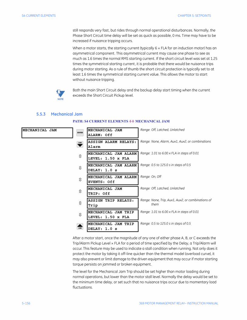
5–156 369 MOTOR MANAGEMENT RELAY– INSTRUCTION MANUAL
S4 CURRENT ELEMENTS CHAPTER 5: SETPOINTS
still responds very fast, but rides through normal operational disturbances. Normally, the Phase Short Circuit time delay will be set as quick as possible, 0 ms. Time may have to be increased if nuisance tripping occurs.
When a motor starts, the starting current (typically 6 × FLA for an induction motor) has an asymmetrical component. This asymmetrical current may cause one phase to see as much as 1.6 times the normal RMS starting current. If the short circuit level was set at 1.25 times the symmetrical starting current, it is probable that there would be nuisance trips during motor starting. As a rule of thumb the short circuit protection is typically set to at least 1.6 times the symmetrical starting current value. This allows the motor to start without nuisance tripping.
Note Both the main Short Circuit delay and the backup delay start timing when the current exceeds the Short Circuit Pickup level.
5.5.3 Mechanical JamPATH: S4 CURRENT ELEMENTS MECHANICAL JAM
After a motor start, once the magnitude of any one of either phase A, B, or C exceeds the Trip/Alarm Pickup Level × FLA for a period of time specified by the Delay, a Trip/Alarm will occur. This feature may be used to indicate a stall condition when running. Not only does it protect the motor by taking it off-line quicker than the thermal model (overload curve), it may also prevent or limit damage to the driven equipment that may occur if motor starting torque persists on jammed or broken equipment.
The level for the Mechanical Jam Trip should be set higher than motor loading during normal operations, but lower than the motor stall level. Normally the delay would be set to the minimum time delay, or set such that no nuisance trips occur due to momentary load fluctuations.
MECHANICAL JAM MECHANICAL JAMALARM: Off
Range: Off, Latched, Unlatched
ASSIGN ALARM RELAYS:Alarm
Range: None, Alarm, Aux1, Aux2, or combinations
MECHANICAL JAM ALARMLEVEL: 1.50 x FLA
Range: 1.01 to 6.00 x FLA in steps of 0.01
MECHANICAL JAM ALARMDELAY: 1.0 s
Range: 0.5 to 125.0 s in steps of 0.5
MECHANICAL JAM ALARMEVENTS: Off
Range: On, Off
MECHANICAL JAMTRIP: Off
Range: Off, Latched, Unlatched
ASSIGN TRIP RELAYS:Trip
Range: None, Trip, Aux1, Aux2, or combinations of them
MECHANICAL JAM TRIPLEVEL: 1.50 x FLA
Range: 1.01 to 6.00 x FLA in steps of 0.01
MECHANICAL JAM TRIPDELAY: 1.0 s
Range: 0.5 to 125.0 s in steps of 0.5
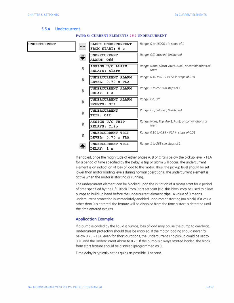
CHAPTER 5: SETPOINTS S4 CURRENT ELEMENTS
369 MOTOR MANAGEMENT RELAY– INSTRUCTION MANUAL 5–157
5.5.4 UndercurrentPATH: S4 CURRENT ELEMENTS UNDERCURRENT
If enabled, once the magnitude of either phase A, B or C falls below the pickup level × FLA for a period of time specified by the Delay, a trip or alarm will occur. The undercurrent element is an indication of loss of load to the motor. Thus, the pickup level should be set lower than motor loading levels during normal operations. The undercurrent element is active when the motor is starting or running.
The undercurrent element can be blocked upon the initiation of a motor start for a period of time specified by the U/C Block From Start setpoint (e.g. this block may be used to allow pumps to build up head before the undercurrent element trips). A value of 0 means undercurrent protection is immediately enabled upon motor starting (no block). If a value other than 0 is entered, the feature will be disabled from the time a start is detected until the time entered expires.
Application Example:
If a pump is cooled by the liquid it pumps, loss of load may cause the pump to overheat. Undercurrent protection should thus be enabled. If the motor loading should never fall below 0.75 × FLA, even for short durations, the Undercurrent Trip pickup could be set to 0.70 and the Undercurrent Alarm to 0.75. If the pump is always started loaded, the block from start feature should be disabled (programmed as 0).
Time delay is typically set as quick as possible, 1 second.
UNDERCURRENT BLOCK UNDERCURRENTFROM START: 0 s
Range: 0 to 15000 s in steps of 1
UNDERCURRENTALARM: Off
Range: Off, Latched, Unlatched
ASSIGN U/C ALARMRELAYS: Alarm
Range: None, Alarm, Aux1, Aux2, or combinations of them
UNDERCURRENT ALARMLEVEL: 0.70 x FLA
Range: 0.10 to 0.99 x FLA in steps of 0.01
UNDERCURRENT ALARMDELAY: 1 s
Range: 1 to 255 s in steps of 1
UNDERCURRENT ALARMEVENTS: Off
Range: On, Off
UNDERCURRENTTRIP: Off
Range: Off, Latched, Unlatched
ASSIGN U/C TRIPRELAYS: Trip
Range: None, Trip, Aux1, Aux2, or combinations of them
UNDERCURRENT TRIPLEVEL: 0.70 x FLA
Range: 0.10 to 0.99 x FLA in steps of 0.01
UNDERCURRENT TRIPDELAY: 1 s
Range: 1 to 255 s in steps of 1
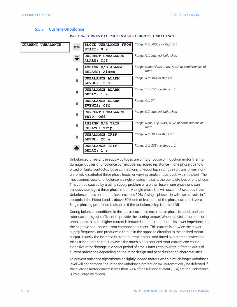
5–158 369 MOTOR MANAGEMENT RELAY– INSTRUCTION MANUAL
S4 CURRENT ELEMENTS CHAPTER 5: SETPOINTS
5.5.5 Current UnbalancePATH: S4 CURRENT ELEMENTS CURRENT UNBALANCE
Unbalanced three phase supply voltages are a major cause of induction motor thermal damage. Causes of unbalance can include: increased resistance in one phase due to a pitted or faulty contactor, loose connections, unequal tap settings in a transformer, non-uniformly distributed three phase loads, or varying single phase loads within a plant. The most serious case of unbalance is single phasing – that is, the complete loss of one phase. This can be caused by a utility supply problem or a blown fuse in one phase and can seriously damage a three phase motor. A single phase trip will occur in 2 seconds if the Unbalance trip is on and the level exceeds 30%. A single phase trip will also activate in 2 seconds if the Motor Load is above 30% and at least one of the phase currents is zero. Single phasing protection is disabled if the Unbalance Trip is turned Off.
During balanced conditions in the stator, current in each motor phase is equal, and the rotor current is just sufficient to provide the turning torque. When the stator currents are unbalanced, a much higher current is induced into the rotor due to its lower impedance to the negative sequence current component present. This current is at twice the power supply frequency and produces a torque in the opposite direction to the desired motor output. Usually the increase in stator current is small and timed overcurrent protection takes a long time to trip. However, the much higher induced rotor current can cause extensive rotor damage in a short period of time. Motors can tolerate different levels of current unbalance depending on the rotor design and heat dissipation characteristics.
To prevent nuisance trips/alarms on lightly loaded motors when a much larger unbalance level will not damage the rotor, the unbalance protection will automatically be defeated if the average motor current is less than 30% of the full load current (IFLA) setting. Unbalance is calculated as follows:
CURRENT UNBALANCE BLOCK UNBALANCE FROMSTART: 0 s
Range: 0 to 5000 s in steps of 1
CURRENT UNBALANCEALARM: Off
Range: Off, Latched, Unlatched
ASSIGN U/B ALARMRELAYS: Alarm
Range: None, Alarm, Aux1, Aux2, or combinations of them
UNBALANCE ALARMLEVEL: 15 %
Range: 4 to 30% in steps of 1
UNBALANCE ALARMDELAY: 1 s
Range: 1 to 255 s in steps of 1
UNBALANCE ALARMEVENTS: Off
Range: On, Off
CURRENT UNBALANCETRIP: Off
Range: Off, Latched, Unlatched
ASSIGN U/B TRIPRELAYS: Trip
Range: None, Trip, Aux1, Aux2, or combinations of them
UNBALANCE TRIPLEVEL: 20 %
Range: 4 to 30% in steps of 1
UNBALANCE TRIPDELAY: 1 s
Range: 1 to 255 s in steps of 1
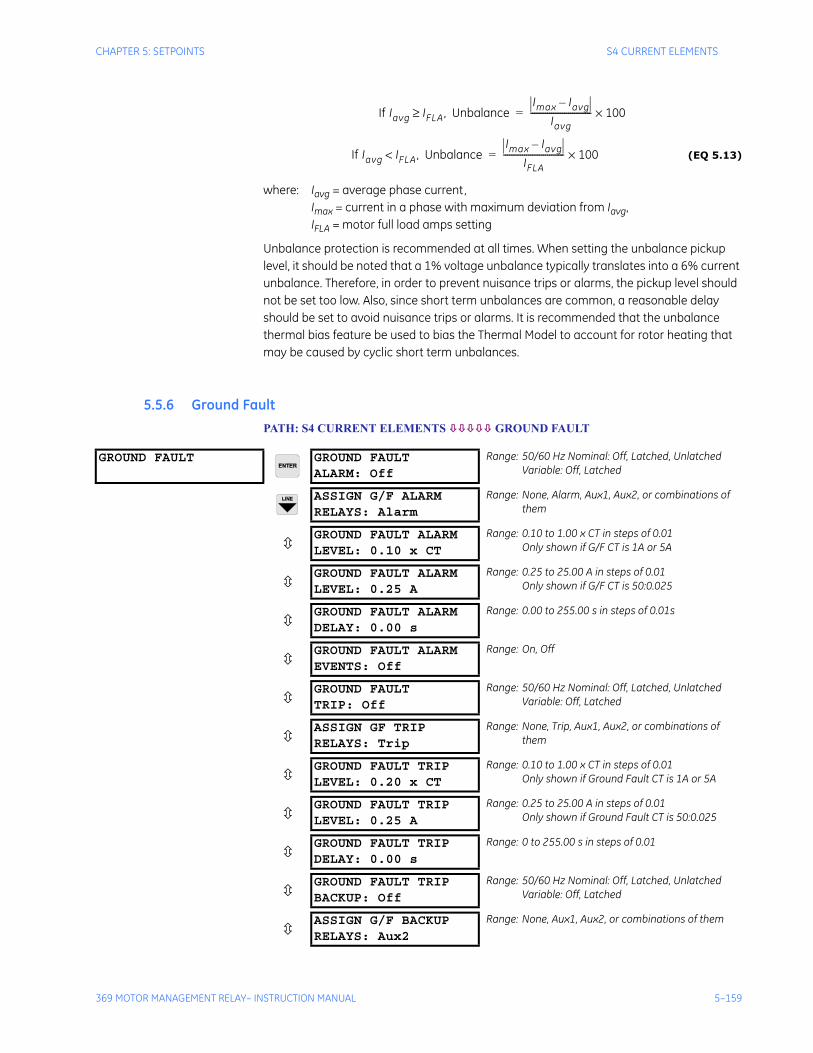
CHAPTER 5: SETPOINTS S4 CURRENT ELEMENTS
369 MOTOR MANAGEMENT RELAY– INSTRUCTION MANUAL 5–159
(EQ 5.13)
where: Iavg = average phase current,Imax = current in a phase with maximum deviation from Iavg,IFLA = motor full load amps setting
Unbalance protection is recommended at all times. When setting the unbalance pickup level, it should be noted that a 1% voltage unbalance typically translates into a 6% current unbalance. Therefore, in order to prevent nuisance trips or alarms, the pickup level should not be set too low. Also, since short term unbalances are common, a reasonable delay should be set to avoid nuisance trips or alarms. It is recommended that the unbalance thermal bias feature be used to bias the Thermal Model to account for rotor heating that may be caused by cyclic short term unbalances.
5.5.6 Ground FaultPATH: S4 CURRENT ELEMENTS GROUND FAULT
If Iavg IFLA, Unbalance≥Imax Iavg–
Iavg----------------------------- 100×=
If Iavg IFLA, Unbalance<Imax Iavg–
IFLA----------------------------- 100×=
GROUND FAULT GROUND FAULTALARM: Off
Range: 50/60 Hz Nominal: Off, Latched, UnlatchedVariable: Off, Latched
ASSIGN G/F ALARMRELAYS: Alarm
Range: None, Alarm, Aux1, Aux2, or combinations of them
GROUND FAULT ALARMLEVEL: 0.10 x CT
Range: 0.10 to 1.00 x CT in steps of 0.01Only shown if G/F CT is 1A or 5A
GROUND FAULT ALARMLEVEL: 0.25 A
Range: 0.25 to 25.00 A in steps of 0.01Only shown if G/F CT is 50:0.025
GROUND FAULT ALARMDELAY: 0.00 s
Range: 0.00 to 255.00 s in steps of 0.01s
GROUND FAULT ALARMEVENTS: Off
Range: On, Off
GROUND FAULTTRIP: Off
Range: 50/60 Hz Nominal: Off, Latched, UnlatchedVariable: Off, Latched
ASSIGN GF TRIPRELAYS: Trip
Range: None, Trip, Aux1, Aux2, or combinations of them
GROUND FAULT TRIPLEVEL: 0.20 x CT
Range: 0.10 to 1.00 x CT in steps of 0.01Only shown if Ground Fault CT is 1A or 5A
GROUND FAULT TRIPLEVEL: 0.25 A
Range: 0.25 to 25.00 A in steps of 0.01Only shown if Ground Fault CT is 50:0.025
GROUND FAULT TRIPDELAY: 0.00 s
Range: 0 to 255.00 s in steps of 0.01
GROUND FAULT TRIPBACKUP: Off
Range: 50/60 Hz Nominal: Off, Latched, UnlatchedVariable: Off, Latched
ASSIGN G/F BACKUPRELAYS: Aux2
Range: None, Aux1, Aux2, or combinations of them

5–160 369 MOTOR MANAGEMENT RELAY– INSTRUCTION MANUAL
S4 CURRENT ELEMENTS CHAPTER 5: SETPOINTS
Once the magnitude of ground current exceeds the Pickup Level for a period of time specified by the Delay, a trip and/or alarm will occur. There is also a backup trip feature that can be enabled. If the backup is On, and a Ground Fault trip has initiated, and the ground current persists for a period of time that exceeds the backup delay, a second ‘backup’ trip will occur. It is intended that this second trip be assigned to Aux1 or Aux2 which would be dedicated as an upstream breaker trip relay. The Ground Fault Trip Backup delay must be set to a time longer than the breaker clearing time.
Note Care must be taken when turning On this feature. If the interrupting device (contactor or circuit breaker) is not rated to break ground fault current (low resistance or solidly grounded systems), the feature should be disabled. Alternately, the feature may be assigned to an auxiliary relay and connected such that it trips an upstream device that is capable of breaking the fault current.
Various situations (e.g. contactor bounce) may cause transient ground currents during motor starting that may exceed the Ground Fault Pickup levels for a very short period of time. The delay can be fine tuned to an application such that it still responds very fast, but rides through normal operational disturbances. Normally, the Ground Fault time delays will be set as quick as possible, 0 ms. Time may have to be increased if nuisance tripping occurs.
Special care must be taken when the ground input is wired to the phase CTs in a residual connection. When a motor starts, the starting current (typically 6 × FLA for an induction motor) has an asymmetrical component. This asymmetrical current may cause one phase to see as much as 1.6 times the normal RMS starting current. This momentary DC component will cause each of the phase CTs to react differently and the net current into the ground input of the 369 will not be negligible. A 20 ms block of the ground fault elements when the motor starts enables the 369 to ride through this momentary ground current signal.
Note Both the main Ground Fault delay and the backup delay start timing when the Ground Fault current exceeds the pickup level.
G/F TRIP BACKUPDELAY: 0.20 s
Range: 0.00 to 255.00 s in steps of 0.01
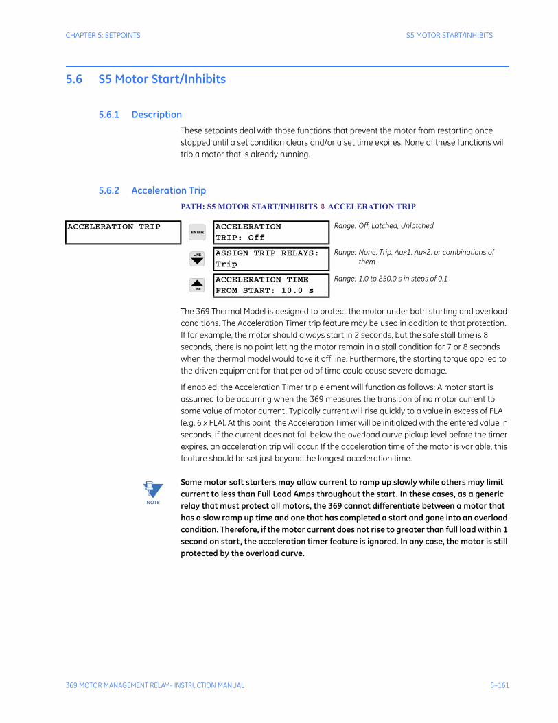
CHAPTER 5: SETPOINTS S5 MOTOR START/INHIBITS
369 MOTOR MANAGEMENT RELAY– INSTRUCTION MANUAL 5–161
5.6 S5 Motor Start/Inhibits
5.6.1 DescriptionThese setpoints deal with those functions that prevent the motor from restarting once stopped until a set condition clears and/or a set time expires. None of these functions will trip a motor that is already running.
5.6.2 Acceleration Trip PATH: S5 MOTOR START/INHIBITS ACCELERATION TRIP
The 369 Thermal Model is designed to protect the motor under both starting and overload conditions. The Acceleration Timer trip feature may be used in addition to that protection. If for example, the motor should always start in 2 seconds, but the safe stall time is 8 seconds, there is no point letting the motor remain in a stall condition for 7 or 8 seconds when the thermal model would take it off line. Furthermore, the starting torque applied to the driven equipment for that period of time could cause severe damage.
If enabled, the Acceleration Timer trip element will function as follows: A motor start is assumed to be occurring when the 369 measures the transition of no motor current to some value of motor current. Typically current will rise quickly to a value in excess of FLA (e.g. 6 x FLA). At this point, the Acceleration Timer will be initialized with the entered value in seconds. If the current does not fall below the overload curve pickup level before the timer expires, an acceleration trip will occur. If the acceleration time of the motor is variable, this feature should be set just beyond the longest acceleration time.
Note Some motor soft starters may allow current to ramp up slowly while others may limit current to less than Full Load Amps throughout the start. In these cases, as a generic relay that must protect all motors, the 369 cannot differentiate between a motor that has a slow ramp up time and one that has completed a start and gone into an overload condition. Therefore, if the motor current does not rise to greater than full load within 1 second on start, the acceleration timer feature is ignored. In any case, the motor is still protected by the overload curve.
ACCELERATION TRIP ACCELERATIONTRIP: Off
Range: Off, Latched, Unlatched
ASSIGN TRIP RELAYS:Trip
Range: None, Trip, Aux1, Aux2, or combinations of them
ACCELERATION TIMEFROM START: 10.0 s
Range: 1.0 to 250.0 s in steps of 0.1
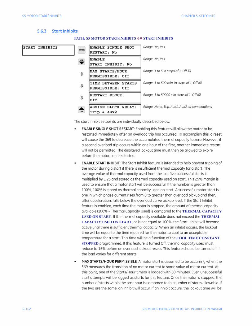
5–162 369 MOTOR MANAGEMENT RELAY– INSTRUCTION MANUAL
S5 MOTOR START/INHIBITS CHAPTER 5: SETPOINTS
5.6.3 Start Inhibits PATH: S5 MOTOR START/INHIBITS START INHIBITS
The start inhibit setpoints are individually described below.
• ENABLE SINGLE SHOT RESTART: Enabling this feature will allow the motor to be restarted immediately after an overload trip has occurred. To accomplish this, a reset will cause the 369 to decrease the accumulated thermal capacity to zero. However, if a second overload trip occurs within one hour of the first, another immediate restart will not be permitted. The displayed lockout time must then be allowed to expire before the motor can be started.
• ENABLE START INHIBIT: The Start Inhibit feature is intended to help prevent tripping of the motor during a start if there is insufficient thermal capacity for a start. The average value of thermal capacity used from the last five successful starts is multiplied by 1.25 and stored as thermal capacity used on start. This 25% margin is used to ensure that a motor start will be successful. If the number is greater than 100%, 100% is stored as thermal capacity used on start. A successful motor start is one in which phase current rises from 0 to greater than overload pickup and then, after acceleration, falls below the overload curve pickup level. If the Start Inhibit feature is enabled, each time the motor is stopped, the amount of thermal capacity available (100% – Thermal Capacity Used) is compared to the THERMAL CAPACITY USED ON START . If the thermal capacity available does not exceed the THERMAL CAPACITY USED ON START , or is not equal to 100%, the Start Inhibit will become active until there is sufficient thermal capacity. When an inhibit occurs, the lockout time will be equal to the time required for the motor to cool to an acceptable temperature for a start. This time will be a function of the COOL TIME CONSTANT STOPPED programmed. If this feature is turned Off, thermal capacity used must reduce to 15% before an overload lockout resets. This feature should be turned off if the load varies for different starts.
• MAX STARTS/HOUR PERMISSIBLE: A motor start is assumed to be occurring when the 369 measures the transition of no motor current to some value of motor current. At this point, one of the Starts/Hour timers is loaded with 60 minutes. Even unsuccessful start attempts will be logged as starts for this feature. Once the motor is stopped, the number of starts within the past hour is compared to the number of starts allowable. If the two are the same, an inhibit will occur. If an inhibit occurs, the lockout time will be
START INHIBITS ENABLE SINGLE SHOTRESTART: No
Range: No, Yes
ENABLESTART INHIBIT: No
Range: No, Yes
MAX STARTS/HOURPERMISSIBLE: Off
Range: 1 to 5 in steps of 1, Off (0)
TIME BETWEEN STARTSPERMISSIBLE: Off
Range: 1 to 500 min. in steps of 1, Off (0)
RESTART BLOCK:Off
Range: 1 to 50000 s in steps of 1, Off (0)
ASSIGN BLOCK RELAY:Trip & Aux2
Range: None, Trip, Aux1, Aux2, or combinations
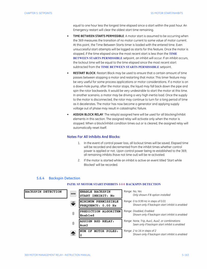
CHAPTER 5: SETPOINTS S5 MOTOR START/INHIBITS
369 MOTOR MANAGEMENT RELAY– INSTRUCTION MANUAL 5–163
equal to one hour less the longest time elapsed since a start within the past hour. An Emergency restart will clear the oldest start time remaining.
• TIME BETWEEN STARTS PERMISSIBLE: A motor start is assumed to be occurring when the 369 measures the transition of no motor current to some value of motor current. At this point, the Time Between Starts timer is loaded with the entered time. Even unsuccessful start attempts will be logged as starts for this feature. Once the motor is stopped, if the time elapsed since the most recent start is less than the TIME BETWEEN STARTS PERMISSIBLE setpoint, an inhibit will occur. If an inhibit occurs, the lockout time will be equal to the time elapsed since the most recent start subtracted from the TIME BETWEEN STARTS PERMISSIBLE setpoint.
• RESTART BLOCK: Restart Block may be used to ensure that a certain amount of time passes between stopping a motor and restarting that motor. This timer feature may be very useful for some process applications or motor considerations. If a motor is on a down-hole pump, after the motor stops, the liquid may fall back down the pipe and spin the rotor backwards. It would be very undesirable to start the motor at this time. In another scenario, a motor may be driving a very high inertia load. Once the supply to the motor is disconnected, the rotor may continue to turn for a long period of time as it decelerates. The motor has now become a generator and applying supply voltage out of phase may result in catastrophic failure.
• ASSIGN BLOCK RELAY: The relay(s) assigned here will be used for all blocking/inhibit elements in this section. The assigned relay will activate only when the motor is stopped. When a block/inhibit condition times out or is cleared, the assigned relay will automatically reset itself.
Notes For All Inhibits And Blocks:
1. In the event of control power loss, all lockout times will be saved. Elapsed time will be recorded and decremented from the inhibit times whether control power is applied or not. Upon control power being re-established to the 369, all remaining inhibits (have not time out) will be re-activated.
2. If the motor is started while an inhibit is active an event titled ‘Start while Blocked’ will be recorded.
5.6.4 Backspin Detection PATH: S5 MOTOR START/INHIBITS BACKSPIN DETECTION
BACKSPIN DETECTION ENABLE BACKSPINSTART INHIBIT: No
Range: No, YesOnly shown if B option installed
MINIMUM PERMISSIBLEFREQUENCY: 0.00 Hz
Range: 0 to 9.99 Hz in steps of 0.01Shown only if backspin start inhibit is enabled
PREDICTION ALGORITHMEnabled
Range: Disabled, EnabledShown only if backspin start inhibit is enabled
ASSIGN BSD RELAY:Aux2
Range: None, Trip, Aux1, Aux2, or combinationsSeen only if backspin start inhibit is enabled
NUM OF MOTOR POLES:2
Range: 2 to 16 in steps of 2Shown only if backspin start inhibit is enabled

5–164 369 MOTOR MANAGEMENT RELAY– INSTRUCTION MANUAL
S5 MOTOR START/INHIBITS CHAPTER 5: SETPOINTS
Immediately after the motor is stopped, backspin detection commences and a backspin start inhibit is activated to prevent the motor from being restarted. The backspin frequency is sensed through the BSD voltage input. If the measured frequency is below the programmed MINIMUM PERMISSIBLE FREQUENCY, the backspin start inhibit will be removed. The time for the motor to reach the MINIMUM PERMISSIBLE FREQUENCY is calculated throughout the backspin state. If the BSD frequency signal is lost prior to reaching the Minimum Permissible Frequency, the inhibit remains active until the prediction time has expired. The calculated Prediction Time and the Backspin State can be viewed in Section 6.3.4 Backspin Metering on page 6–208.
Application:
Backspin protection is typically used on down hole pump motors which can be located several kilometers underground. Check valves are often used to prevent flow reversal when the pump stops. Very often however, the flow reverses due to faulty or non existent check valves, causing the pump impeller to rotate the motor in the reverse direction. Starting the motor during this period of reverse rotation (back-spinning) may result in motor damage. Backspin detection ensures that the motor can only be started when the motor has slowed to within acceptable limits. Without backspin detection a long time delay had to be used as a start permissive to ensure the motor had slowed to a safe speed.
Note These setpoints are only visible when option B has been installed.
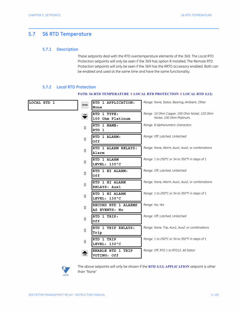
CHAPTER 5: SETPOINTS S6 RTD TEMPERATURE
369 MOTOR MANAGEMENT RELAY– INSTRUCTION MANUAL 5–165
5.7 S6 RTD Temperature
5.7.1 DescriptionThese setpoints deal with the RTD overtemperature elements of the 369. The Local RTD Protection setpoints will only be seen if the 369 has option R installed. The Remote RTD Protection setpoints will only be seen if the 369 has the RRTD accessory enabled. Both can be enabled and used at the same time and have the same functionality.
5.7.2 Local RTD ProtectionPATH: S6 RTD TEMPERATURE LOCAL RTD PROTECTION LOCAL RTD 1(12)
Note The above setpoints will only be shown if the RTD 1(12) APPLICATION setpoint is other than “None”
LOCAL RTD 1 RTD 1 APPLICATION:None
Range: None, Stator, Bearing, Ambient, Other
RTD 1 TYPE:100 Ohm Platinum
Range 10 Ohm Copper, 100 Ohm Nickel, 120 Ohm Nickel, 100 Ohm Platinum.
RTD 1 NAME:RTD 1
Range: 8 alphanumeric characters
RTD 1 ALARM:Off
Range: Off, Latched, Unlatched
RTD 1 ALARM RELAYS:Alarm
Range: None, Alarm, Aux1, Aux2, or combinations
RTD 1 ALARMLEVEL: 130°C
Range: 1 to 200°C or 34 to 392°F in steps of 1
RTD 1 HI ALARM:Off
Range: Off, Latched, Unlatched
RTD 1 HI ALARMRELAYS: Aux1
Range: None, Alarm, Aux1, Aux2, or combinations
RTD 1 HI ALARMLEVEL: 130°C
Range: 1 to 200°C or 34 to 392°F in steps of 1
RECORD RTD 1 ALARMSAS EVENTS: No
Range: No, Yes
RTD 1 TRIP:Off
Range: Off, Latched, Unlatched
RTD 1 TRIP RELAYS:Trip
Range: None, Trip, Aux1, Aux2, or combinations
RTD 1 TRIPLEVEL: 130°C
Range: 1 to 200°C or 34 to 392°F in steps of 1
ENABLE RTD 1 TRIPVOTING: Off
Range: Off, RTD 1 to RTD12, All Stator
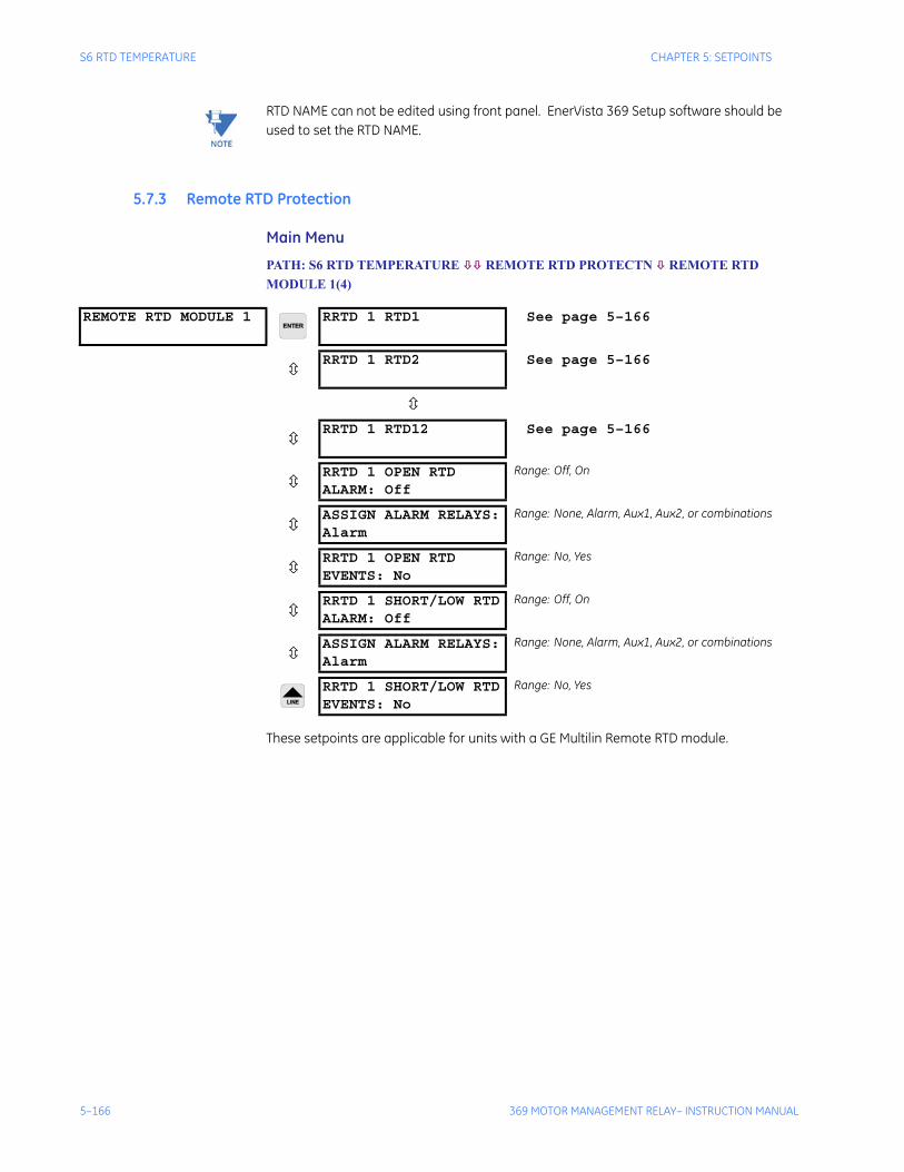
5–166 369 MOTOR MANAGEMENT RELAY– INSTRUCTION MANUAL
S6 RTD TEMPERATURE CHAPTER 5: SETPOINTS
Note RTD NAME can not be edited using front panel. EnerVista 369 Setup software should be used to set the RTD NAME.
5.7.3 Remote RTD Protection
Main Menu
PATH: S6 RTD TEMPERATURE REMOTE RTD PROTECTN REMOTE RTD MODULE 1(4)
These setpoints are applicable for units with a GE Multilin Remote RTD module.
REMOTE RTD MODULE 1 RRTD 1 RTD1 See page 5–166
RRTD 1 RTD2 See page 5–166
RRTD 1 RTD12 See page 5–166
RRTD 1 OPEN RTDALARM: Off
Range: Off, On
ASSIGN ALARM RELAYS:Alarm
Range: None, Alarm, Aux1, Aux2, or combinations
RRTD 1 OPEN RTDEVENTS: No
Range: No, Yes
RRTD 1 SHORT/LOW RTDALARM: Off
Range: Off, On
ASSIGN ALARM RELAYS:Alarm
Range: None, Alarm, Aux1, Aux2, or combinations
RRTD 1 SHORT/LOW RTDEVENTS: No
Range: No, Yes
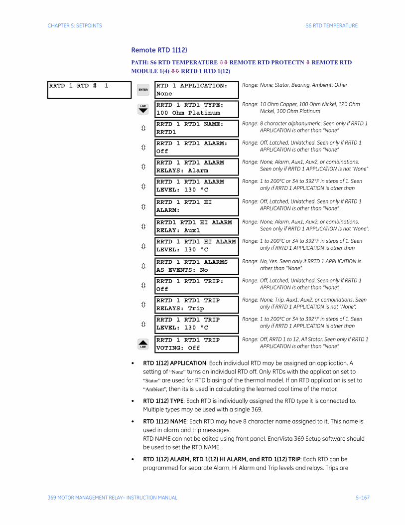
CHAPTER 5: SETPOINTS S6 RTD TEMPERATURE
369 MOTOR MANAGEMENT RELAY– INSTRUCTION MANUAL 5–167
Remote RTD 1(12)
PATH: S6 RTD TEMPERATURE REMOTE RTD PROTECTN REMOTE RTD MODULE 1(4) RRTD 1 RTD 1(12)
• RTD 1(12) APPLICATION: Each individual RTD may be assigned an application. A setting of “None” turns an individual RTD off. Only RTDs with the application set to “Stator” are used for RTD biasing of the thermal model. If an RTD application is set to “Ambient”, then its is used in calculating the learned cool time of the motor.
• RTD 1(12) TYPE: Each RTD is individually assigned the RTD type it is connected to. Multiple types may be used with a single 369.
• RTD 1(12) NAME: Each RTD may have 8 character name assigned to it . This name is used in alarm and trip messages. RTD NAME can not be edited using front panel. EnerVista 369 Setup software should be used to set the RTD NAME.
• RTD 1(12) ALARM, RTD 1(12) HI ALARM, and RTD 1(12) TRIP: Each RTD can be programmed for separate Alarm, Hi Alarm and Trip levels and relays. Trips are
RRTD 1 RTD # 1 RTD 1 APPLICATION:None
Range: None, Stator, Bearing, Ambient, Other
RRTD 1 RTD1 TYPE:100 Ohm Platinum
Range: 10 Ohm Copper, 100 Ohm Nickel, 120 Ohm Nickel, 100 Ohm Platinum
RRTD 1 RTD1 NAME:RRTD1
Range: 8 character alphanumeric. Seen only if RRTD 1 APPLICATION is other than “None”
RRTD 1 RTD1 ALARM:Off
Range: Off, Latched, Unlatched. Seen only if RRTD 1 APPLICATION is other than “None”
RRTD 1 RTD1 ALARMRELAYS: Alarm
Range: None, Alarm, Aux1, Aux2, or combinations. Seen only if RRTD 1 APPLICATION is not “None”
RRTD 1 RTD1 ALARMLEVEL: 130 °C
Range: 1 to 200°C or 34 to 392°F in steps of 1. Seen only if RRTD 1 APPLICATION is other than
RRTD 1 RTD1 HI ALARM:
Range: Off, Latched, Unlatched. Seen only if RRTD 1 APPLICATION is other than “None”.
RRTD1 RTD1 HI ALARMRELAY: Aux1
Range: None, Alarm, Aux1, Aux2, or combinations. Seen only if RRTD 1 APPLICATION is not “None”.
RRTD 1 RTD1 HI ALARMLEVEL: 130 °C
Range: 1 to 200°C or 34 to 392°F in steps of 1. Seen only if RRTD 1 APPLICATION is other than
RRTD 1 RTD1 ALARMSAS EVENTS: No
Range: No, Yes. Seen only if RRTD 1 APPLICATION is other than “None”.
RRTD 1 RTD1 TRIP:Off
Range: Off, Latched, Unlatched. Seen only if RRTD 1 APPLICATION is other than “None”.
RRTD 1 RTD1 TRIPRELAYS: Trip
Range: None, Trip, Aux1, Aux2, or combinations. Seen only if RRTD 1 APPLICATION is not “None”.
RRTD 1 RTD1 TRIPLEVEL: 130 °C
Range: 1 to 200°C or 34 to 392°F in steps of 1. Seen only if RRTD 1 APPLICATION is other than
RRTD 1 RTD1 TRIPVOTING: Off
Range: Off, RRTD 1 to 12, All Stator. Seen only if RRTD 1 APPLICATION is other than “None”
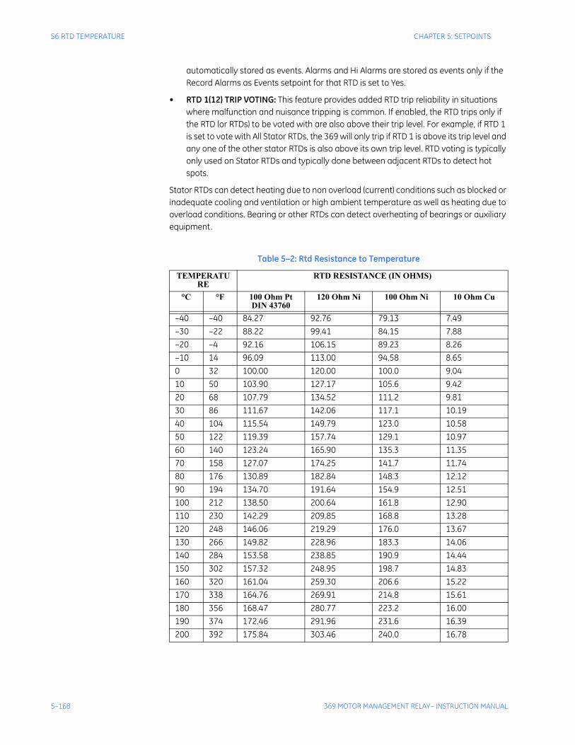
5–168 369 MOTOR MANAGEMENT RELAY– INSTRUCTION MANUAL
S6 RTD TEMPERATURE CHAPTER 5: SETPOINTS
automatically stored as events. Alarms and Hi Alarms are stored as events only if the Record Alarms as Events setpoint for that RTD is set to Yes.
• RTD 1(12) TRIP VOTING: This feature provides added RTD trip reliability in situations where malfunction and nuisance tripping is common. If enabled, the RTD trips only if the RTD (or RTDs) to be voted with are also above their trip level. For example, if RTD 1 is set to vote with All Stator RTDs, the 369 will only trip if RTD 1 is above its trip level and any one of the other stator RTDs is also above its own trip level. RTD voting is typically only used on Stator RTDs and typically done between adjacent RTDs to detect hot spots.
Stator RTDs can detect heating due to non overload (current) conditions such as blocked or inadequate cooling and ventilation or high ambient temperature as well as heating due to overload conditions. Bearing or other RTDs can detect overheating of bearings or auxiliary equipment.
Table 5–2: Rtd Resistance to Temperature
TEMPERATURE
RTD RESISTANCE (IN OHMS)
°C °F 100 Ohm PtDIN 43760
120 Ohm Ni 100 Ohm Ni 10 Ohm Cu
–40 –40 84.27 92.76 79.13 7.49–30 –22 88.22 99.41 84.15 7.88–20 –4 92.16 106.15 89.23 8.26–10 14 96.09 113.00 94.58 8.650 32 100.00 120.00 100.0 9.0410 50 103.90 127.17 105.6 9.4220 68 107.79 134.52 111.2 9.8130 86 111.67 142.06 117.1 10.1940 104 115.54 149.79 123.0 10.5850 122 119.39 157.74 129.1 10.9760 140 123.24 165.90 135.3 11.3570 158 127.07 174.25 141.7 11.7480 176 130.89 182.84 148.3 12.1290 194 134.70 191.64 154.9 12.51100 212 138.50 200.64 161.8 12.90110 230 142.29 209.85 168.8 13.28120 248 146.06 219.29 176.0 13.67130 266 149.82 228.96 183.3 14.06140 284 153.58 238.85 190.9 14.44150 302 157.32 248.95 198.7 14.83160 320 161.04 259.30 206.6 15.22170 338 164.76 269.91 214.8 15.61180 356 168.47 280.77 223.2 16.00190 374 172.46 291.96 231.6 16.39200 392 175.84 303.46 240.0 16.78
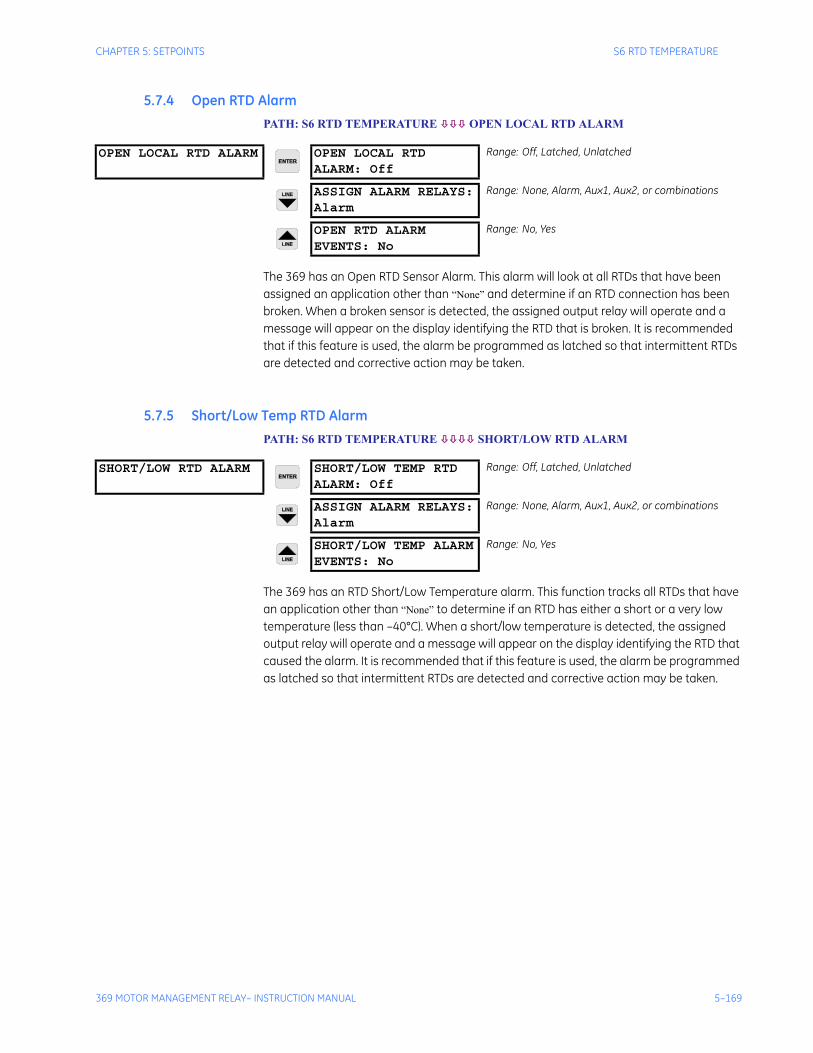
CHAPTER 5: SETPOINTS S6 RTD TEMPERATURE
369 MOTOR MANAGEMENT RELAY– INSTRUCTION MANUAL 5–169
5.7.4 Open RTD AlarmPATH: S6 RTD TEMPERATURE OPEN LOCAL RTD ALARM
The 369 has an Open RTD Sensor Alarm. This alarm will look at all RTDs that have been assigned an application other than “None” and determine if an RTD connection has been broken. When a broken sensor is detected, the assigned output relay will operate and a message will appear on the display identifying the RTD that is broken. It is recommended that if this feature is used, the alarm be programmed as latched so that intermittent RTDs are detected and corrective action may be taken.
5.7.5 Short/Low Temp RTD AlarmPATH: S6 RTD TEMPERATURE SHORT/LOW RTD ALARM
The 369 has an RTD Short/Low Temperature alarm. This function tracks all RTDs that have an application other than “None” to determine if an RTD has either a short or a very low temperature (less than –40°C). When a short/low temperature is detected, the assigned output relay will operate and a message will appear on the display identifying the RTD that caused the alarm. It is recommended that if this feature is used, the alarm be programmed as latched so that intermittent RTDs are detected and corrective action may be taken.
OPEN LOCAL RTD ALARM OPEN LOCAL RTDALARM: Off
Range: Off, Latched, Unlatched
ASSIGN ALARM RELAYS:Alarm
Range: None, Alarm, Aux1, Aux2, or combinations
OPEN RTD ALARMEVENTS: No
Range: No, Yes
SHORT/LOW RTD ALARM SHORT/LOW TEMP RTDALARM: Off
Range: Off, Latched, Unlatched
ASSIGN ALARM RELAYS:Alarm
Range: None, Alarm, Aux1, Aux2, or combinations
SHORT/LOW TEMP ALARMEVENTS: No
Range: No, Yes
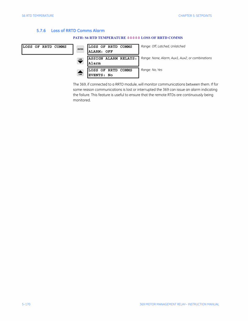
5–170 369 MOTOR MANAGEMENT RELAY– INSTRUCTION MANUAL
S6 RTD TEMPERATURE CHAPTER 5: SETPOINTS
5.7.6 Loss of RRTD Comms AlarmPATH: S6 RTD TEMPERATURE LOSS OF RRTD COMMS
The 369, if connected to a RRTD module, will monitor communications between them. If for some reason communications is lost or interrupted the 369 can issue an alarm indicating the failure. This feature is useful to ensure that the remote RTDs are continuously being monitored.
LOSS OF RRTD COMMS LOSS OF RRTD COMMSALARM: OFF
Range: Off, Latched, Unlatched
ASSIGN ALARM RELAYS:Alarm
Range: None, Alarm, Aux1, Aux2, or combinations
LOSS OF RRTD COMMSEVENTS: No
Range: No, Yes
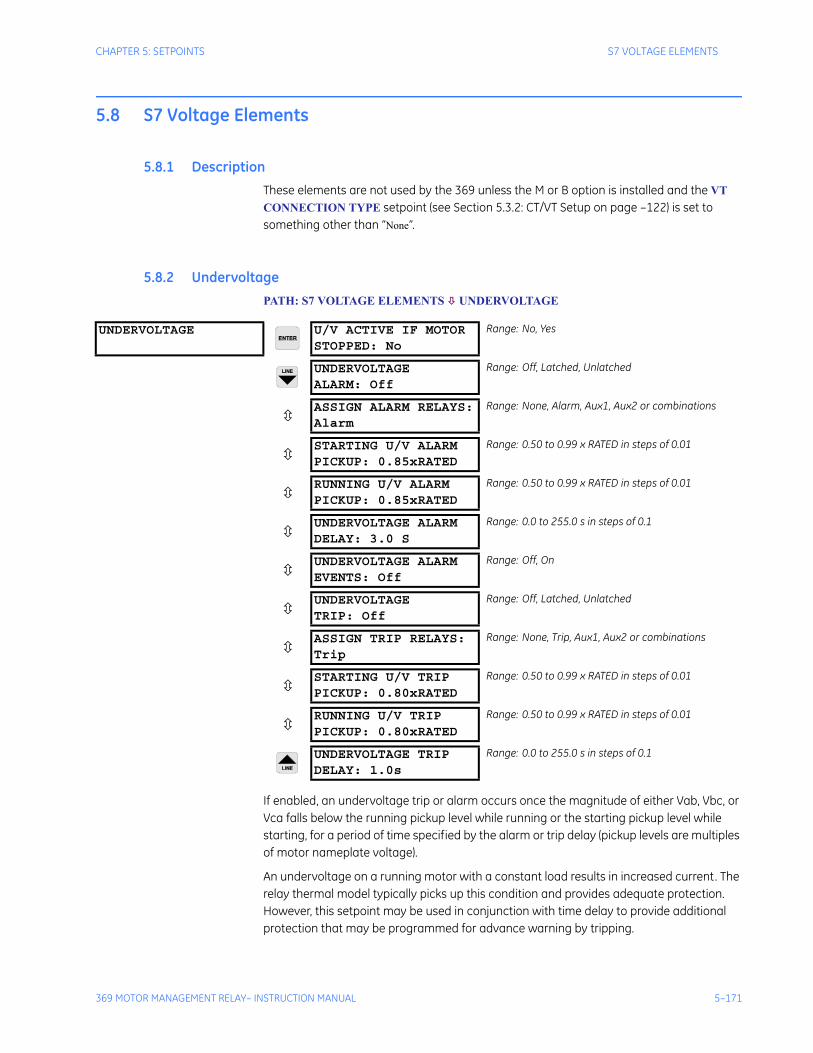
CHAPTER 5: SETPOINTS S7 VOLTAGE ELEMENTS
369 MOTOR MANAGEMENT RELAY– INSTRUCTION MANUAL 5–171
5.8 S7 Voltage Elements
5.8.1 DescriptionThese elements are not used by the 369 unless the M or B option is installed and the VT CONNECTION TYPE setpoint (see Section 5.3.2: CT/VT Setup on page –122) is set to something other than “None”.
5.8.2 UndervoltagePATH: S7 VOLTAGE ELEMENTS UNDERVOLTAGE
If enabled, an undervoltage trip or alarm occurs once the magnitude of either Vab, Vbc, or Vca falls below the running pickup level while running or the starting pickup level while starting, for a period of time specified by the alarm or trip delay (pickup levels are multiples of motor nameplate voltage).
An undervoltage on a running motor with a constant load results in increased current. The relay thermal model typically picks up this condition and provides adequate protection. However, this setpoint may be used in conjunction with time delay to provide additional protection that may be programmed for advance warning by tripping.
UNDERVOLTAGE U/V ACTIVE IF MOTORSTOPPED: No
Range: No, Yes
UNDERVOLTAGEALARM: Off
Range: Off, Latched, Unlatched
ASSIGN ALARM RELAYS:Alarm
Range: None, Alarm, Aux1, Aux2 or combinations
STARTING U/V ALARMPICKUP: 0.85xRATED
Range: 0.50 to 0.99 x RATED in steps of 0.01
RUNNING U/V ALARMPICKUP: 0.85xRATED
Range: 0.50 to 0.99 x RATED in steps of 0.01
UNDERVOLTAGE ALARMDELAY: 3.0 S
Range: 0.0 to 255.0 s in steps of 0.1
UNDERVOLTAGE ALARMEVENTS: Off
Range: Off, On
UNDERVOLTAGETRIP: Off
Range: Off, Latched, Unlatched
ASSIGN TRIP RELAYS:Trip
Range: None, Trip, Aux1, Aux2 or combinations
STARTING U/V TRIPPICKUP: 0.80xRATED
Range: 0.50 to 0.99 x RATED in steps of 0.01
RUNNING U/V TRIPPICKUP: 0.80xRATED
Range: 0.50 to 0.99 x RATED in steps of 0.01
UNDERVOLTAGE TRIPDELAY: 1.0s
Range: 0.0 to 255.0 s in steps of 0.1
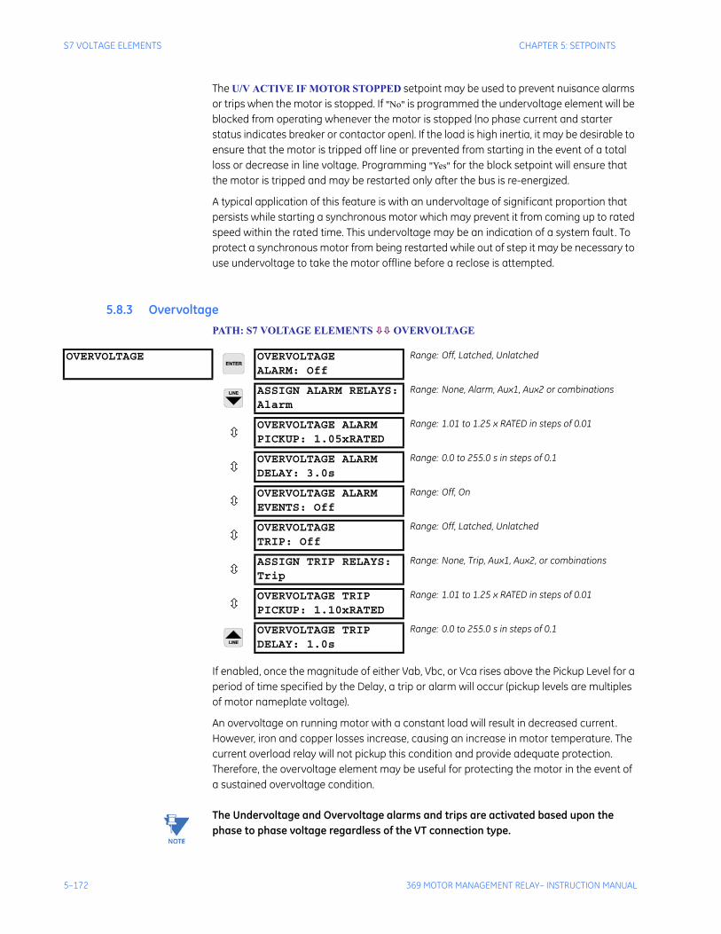
5–172 369 MOTOR MANAGEMENT RELAY– INSTRUCTION MANUAL
S7 VOLTAGE ELEMENTS CHAPTER 5: SETPOINTS
The U/V ACTIVE IF MOTOR STOPPED setpoint may be used to prevent nuisance alarms or trips when the motor is stopped. If "No" is programmed the undervoltage element will be blocked from operating whenever the motor is stopped (no phase current and starter status indicates breaker or contactor open). If the load is high inertia, it may be desirable to ensure that the motor is tripped off line or prevented from starting in the event of a total loss or decrease in line voltage. Programming "Yes" for the block setpoint will ensure that the motor is tripped and may be restarted only after the bus is re-energized.
A typical application of this feature is with an undervoltage of significant proportion that persists while starting a synchronous motor which may prevent it from coming up to rated speed within the rated time. This undervoltage may be an indication of a system fault. To protect a synchronous motor from being restarted while out of step it may be necessary to use undervoltage to take the motor offline before a reclose is attempted.
5.8.3 OvervoltagePATH: S7 VOLTAGE ELEMENTS OVERVOLTAGE
If enabled, once the magnitude of either Vab, Vbc, or Vca rises above the Pickup Level for a period of time specified by the Delay, a trip or alarm will occur (pickup levels are multiples of motor nameplate voltage).
An overvoltage on running motor with a constant load will result in decreased current. However, iron and copper losses increase, causing an increase in motor temperature. The current overload relay will not pickup this condition and provide adequate protection. Therefore, the overvoltage element may be useful for protecting the motor in the event of a sustained overvoltage condition.
Note The Undervoltage and Overvoltage alarms and trips are activated based upon the phase to phase voltage regardless of the VT connection type.
OVERVOLTAGE OVERVOLTAGEALARM: Off
Range: Off, Latched, Unlatched
ASSIGN ALARM RELAYS:Alarm
Range: None, Alarm, Aux1, Aux2 or combinations
OVERVOLTAGE ALARMPICKUP: 1.05xRATED
Range: 1.01 to 1.25 x RATED in steps of 0.01
OVERVOLTAGE ALARMDELAY: 3.0s
Range: 0.0 to 255.0 s in steps of 0.1
OVERVOLTAGE ALARMEVENTS: Off
Range: Off, On
OVERVOLTAGETRIP: Off
Range: Off, Latched, Unlatched
ASSIGN TRIP RELAYS:Trip
Range: None, Trip, Aux1, Aux2, or combinations
OVERVOLTAGE TRIPPICKUP: 1.10xRATED
Range: 1.01 to 1.25 x RATED in steps of 0.01
OVERVOLTAGE TRIPDELAY: 1.0s
Range: 0.0 to 255.0 s in steps of 0.1
CHAPTER 5: SETPOINTS S7 VOLTAGE ELEMENTS
369 MOTOR MANAGEMENT RELAY– INSTRUCTION MANUAL 5–173
5.8.4 Phase Reversal PATH: S7 VOLTAGE ELEMENTS PHASE REVERSAL
The 369 Relay can detect reversed phases on the motor. When enabled, this element detects the phase sequence of both the three-phase voltages and the three-phase currents as measured by the relay. If the measured three-phase voltages are greater than 50% of the motor rated voltage the Phase Reversal element will ignore the currents and perform only voltage phase reversal detection.
If the three-phase voltages are not greater than 50% of the motor rated voltage, or voltages are not available on relay terminals, the Phase reversal element will be activated after the measured currents are above 5% of the motor FLA. When the Two-speed Motor feature is enabled, and Speed 1 is active, the Phase Reversal element will be activated when currents are greater than 5% FLA of the Speed 1 FLA setpoint. When Speed 2 is active, the Phase Reversal element will be activated after the currents become greater than 5% FLA of the Speed 2 FLA setpoint.
The element detects the phase reversal condition within 500-700ms and will issue a trip and block the motor start.
The setting of the phase sequence under S2 SYSTEM SETUP/ CT/VT SETUP/SYSTEM PHASE SEQUENCE should match the phase sequence of the three-phase voltages measured on the relay terminals. For Two-Speed Motor applications, the setting under S2 SYSTEM SETUP/ CT/VT SETUP/SYSTEM PHASE SEQUENCE should match the phase sequence of the currents measured by the relay terminals when in Speed 1.
If the Two-Speed Motor feature is used for Forward and Reverse motor applications, the setting of the phase sequence under S2 SYSTEM SETUP/CT/VT SETUP/SPEED2 SYSTEM PHASE SEQUENCE will be opposite to the setting of the phase sequence under S2 SYSTEM SETUP/ CT/VT SETUP/SYSTEM PHASE SEQUENCE.
When the voltage phase reversal detection is active, the phase rotation of the measured voltages is compared only to S2 SYSTEM SETUP/ CT/VT SETUP/SYSTEM PHASE SEQUENCE setting, whether the Two-Speed Motor feature is enabled or not.
Note If the two-speed feature is used for Forward/Reverse motor applications, the phase sequence of VT input to the 369 and the SYSTEM PHASE SEQUENCE setpoint in the 369 relay must match the phase sequence required for Forward rotation of the motor. For correct operation of Phase Reversal trip, the phase sequence of the VT input connections should not be altered in reverse rotation of the motor.
When the phase reversal detection based on currents is active, the phase rotation of the measured currents is compared to S2 SYSTEM SETUP/ CT/VT SETUP/SYSTEM PHASE SEQUENCE setting when in Speed 1, and to S2 SYSTEM SETUP/CT/VT SETUP/SPEED2 SYSTEM PHASE SEQUENCE, when in Speed 2.
PHASE REVERSAL PHASE REVERSALTRIP: Off
Range: Off, Latched, Unlatched
ASSIGN TRIP RELAYS:Trip
Range: None, Trip, Aux1, Aux2, or combinations
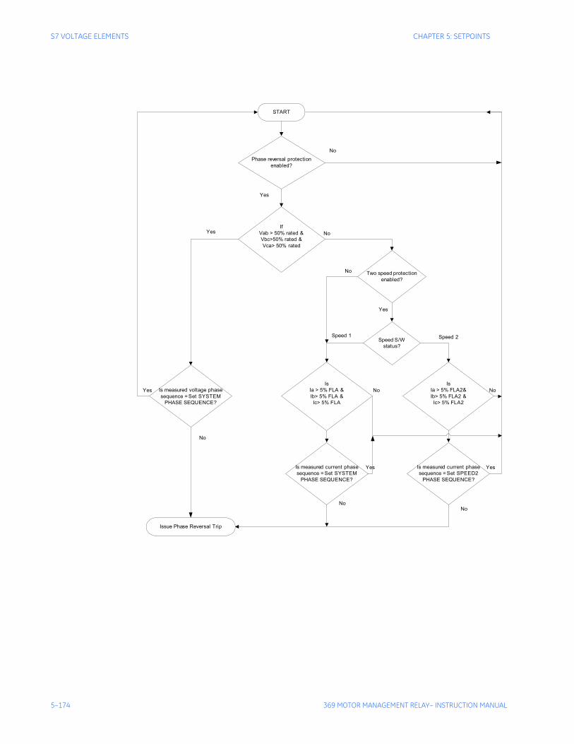
5–174 369 MOTOR MANAGEMENT RELAY– INSTRUCTION MANUAL
S7 VOLTAGE ELEMENTS CHAPTER 5: SETPOINTS
Phase reversal protectionenabled?
IfVab > 50% rated &Vbc>50% rated &Vca> 50% rated
Two speed protectionenabled?
Is measured voltage phasesequence = Set SYSTEM
PHASE SEQUENCE?
Yes
Yes
Yes
IsIa > 5% FLA &Ib> 5% FLA &Ic> 5% FLA
IsIa > 5% FLA2&Ib> 5% FLA2 &Ic> 5% FLA2
Speed S/Wstatus?
No
No
No
Yes
Speed 1 Speed 2
Is measured current phasesequence = Set SYSTEM
PHASE SEQUENCE?
Is measured current phasesequence = Set SPEED2
PHASE SEQUENCE?
No
No
No
NoNo
YesYes
START
Issue Phase Reversal Trip
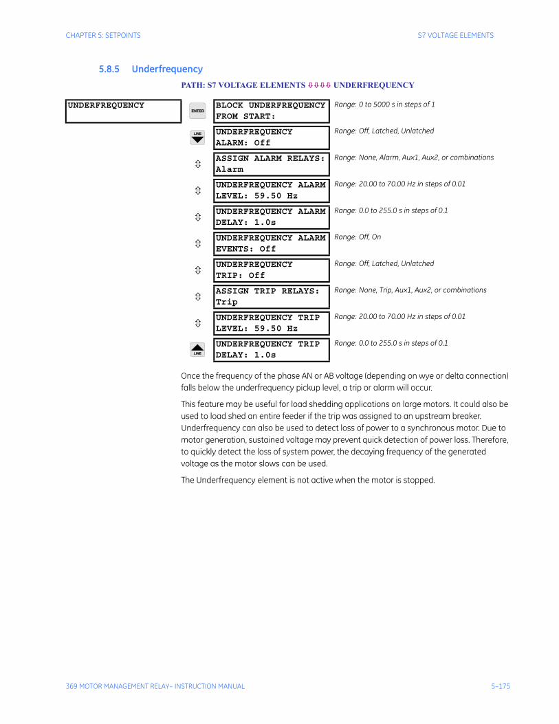
CHAPTER 5: SETPOINTS S7 VOLTAGE ELEMENTS
369 MOTOR MANAGEMENT RELAY– INSTRUCTION MANUAL 5–175
5.8.5 UnderfrequencyPATH: S7 VOLTAGE ELEMENTS UNDERFREQUENCY
Once the frequency of the phase AN or AB voltage (depending on wye or delta connection) falls below the underfrequency pickup level, a trip or alarm will occur.
This feature may be useful for load shedding applications on large motors. It could also be used to load shed an entire feeder if the trip was assigned to an upstream breaker. Underfrequency can also be used to detect loss of power to a synchronous motor. Due to motor generation, sustained voltage may prevent quick detection of power loss. Therefore, to quickly detect the loss of system power, the decaying frequency of the generated voltage as the motor slows can be used.
The Underfrequency element is not active when the motor is stopped.
UNDERFREQUENCY BLOCK UNDERFREQUENCYFROM START:
Range: 0 to 5000 s in steps of 1
UNDERFREQUENCYALARM: Off
Range: Off, Latched, Unlatched
ASSIGN ALARM RELAYS:Alarm
Range: None, Alarm, Aux1, Aux2, or combinations
UNDERFREQUENCY ALARMLEVEL: 59.50 Hz
Range: 20.00 to 70.00 Hz in steps of 0.01
UNDERFREQUENCY ALARMDELAY: 1.0s
Range: 0.0 to 255.0 s in steps of 0.1
UNDERFREQUENCY ALARMEVENTS: Off
Range: Off, On
UNDERFREQUENCYTRIP: Off
Range: Off, Latched, Unlatched
ASSIGN TRIP RELAYS:Trip
Range: None, Trip, Aux1, Aux2, or combinations
UNDERFREQUENCY TRIPLEVEL: 59.50 Hz
Range: 20.00 to 70.00 Hz in steps of 0.01
UNDERFREQUENCY TRIPDELAY: 1.0s
Range: 0.0 to 255.0 s in steps of 0.1
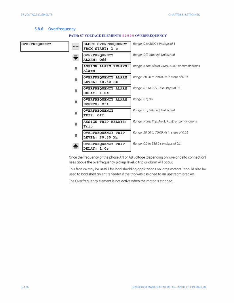
5–176 369 MOTOR MANAGEMENT RELAY– INSTRUCTION MANUAL
S7 VOLTAGE ELEMENTS CHAPTER 5: SETPOINTS
5.8.6 Overfrequency PATH: S7 VOLTAGE ELEMENTS OVERFREQUENCY
Once the frequency of the phase AN or AB voltage (depending on wye or delta connection) rises above the overfrequency pickup level, a trip or alarm will occur.
This feature may be useful for load shedding applications on large motors. It could also be used to load shed an entire feeder if the trip was assigned to an upstream breaker.
The Overfrequency element is not active when the motor is stopped.
OVERFREQUENCY BLOCK OVERFREQUENCYFROM START: 1 s
Range: 0 to 5000 s in steps of 1
OVERFREQUENCYALARM: Off
Range: Off, Latched, Unlatched
ASSIGN ALARM RELAYS:Alarm
Range: None, Alarm, Aux1, Aux2, or combinations
OVERFREQUENCY ALARMLEVEL: 60.50 Hz
Range: 20.00 to 70.00 Hz in steps of 0.01
OVERFREQUENCY ALARMDELAY: 1.0s
Range: 0.0 to 255.0 s in steps of 0.1
OVERFREQUENCY ALARMEVENTS: Off
Range: Off, On
OVERFREQUENCYTRIP: Off
Range: Off, Latched, Unlatched
ASSIGN TRIP RELAYS:Trip
Range: None, Trip, Aux1, Aux2, or combinations
OVERFREQUENCY TRIPLEVEL: 60.50 Hz
Range: 20.00 to 70.00 Hz in steps of 0.01
OVERFREQUENCY TRIPDELAY: 1.0s
Range: 0.0 to 255.0 s in steps of 0.1
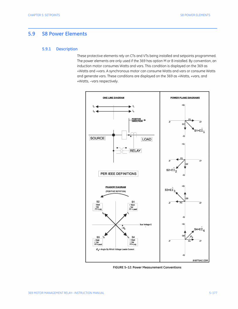
CHAPTER 5: SETPOINTS S8 POWER ELEMENTS
369 MOTOR MANAGEMENT RELAY– INSTRUCTION MANUAL 5–177
5.9 S8 Power Elements
5.9.1 DescriptionThese protective elements rely on CTs and VTs being installed and setpoints programmed. The power elements are only used if the 369 has option M or B installed. By convention, an induction motor consumes Watts and vars. This condition is displayed on the 369 as +Watts and +vars. A synchronous motor can consume Watts and vars or consume Watts and generate vars. These conditions are displayed on the 369 as +Watts, +vars, and +Watts, –vars respectively.
FIGURE 5–12: Power Measurement Conventions
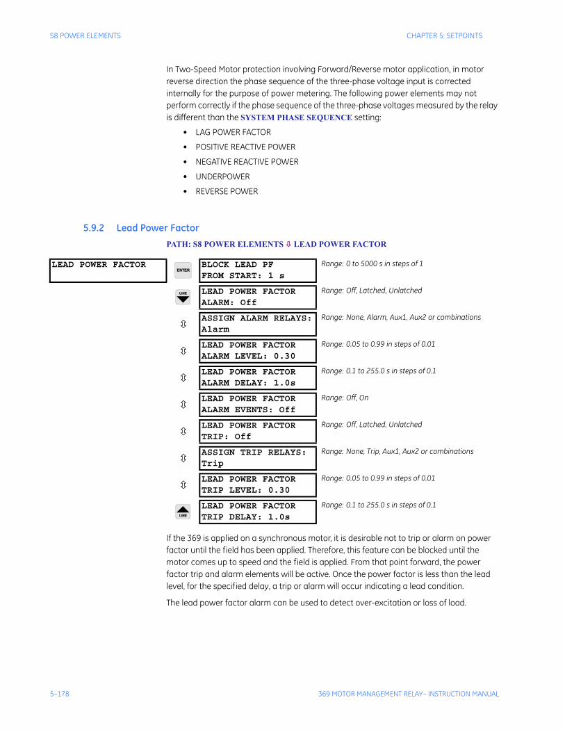
5–178 369 MOTOR MANAGEMENT RELAY– INSTRUCTION MANUAL
S8 POWER ELEMENTS CHAPTER 5: SETPOINTS
In Two-Speed Motor protection involving Forward/Reverse motor application, in motor reverse direction the phase sequence of the three-phase voltage input is corrected internally for the purpose of power metering. The following power elements may not perform correctly if the phase sequence of the three-phase voltages measured by the relay is different than the SYSTEM PHASE SEQUENCE setting:
• LAG POWER FACTOR
• POSITIVE REACTIVE POWER
• NEGATIVE REACTIVE POWER
• UNDERPOWER
• REVERSE POWER
5.9.2 Lead Power FactorPATH: S8 POWER ELEMENTS LEAD POWER FACTOR
If the 369 is applied on a synchronous motor, it is desirable not to trip or alarm on power factor until the field has been applied. Therefore, this feature can be blocked until the motor comes up to speed and the field is applied. From that point forward, the power factor trip and alarm elements will be active. Once the power factor is less than the lead level, for the specified delay, a trip or alarm will occur indicating a lead condition.
The lead power factor alarm can be used to detect over-excitation or loss of load.
LEAD POWER FACTOR BLOCK LEAD PFFROM START: 1 s
Range: 0 to 5000 s in steps of 1
LEAD POWER FACTORALARM: Off
Range: Off, Latched, Unlatched
ASSIGN ALARM RELAYS:Alarm
Range: None, Alarm, Aux1, Aux2 or combinations
LEAD POWER FACTORALARM LEVEL: 0.30
Range: 0.05 to 0.99 in steps of 0.01
LEAD POWER FACTORALARM DELAY: 1.0s
Range: 0.1 to 255.0 s in steps of 0.1
LEAD POWER FACTORALARM EVENTS: Off
Range: Off, On
LEAD POWER FACTORTRIP: Off
Range: Off, Latched, Unlatched
ASSIGN TRIP RELAYS:Trip
Range: None, Trip, Aux1, Aux2 or combinations
LEAD POWER FACTORTRIP LEVEL: 0.30
Range: 0.05 to 0.99 in steps of 0.01
LEAD POWER FACTORTRIP DELAY: 1.0s
Range: 0.1 to 255.0 s in steps of 0.1
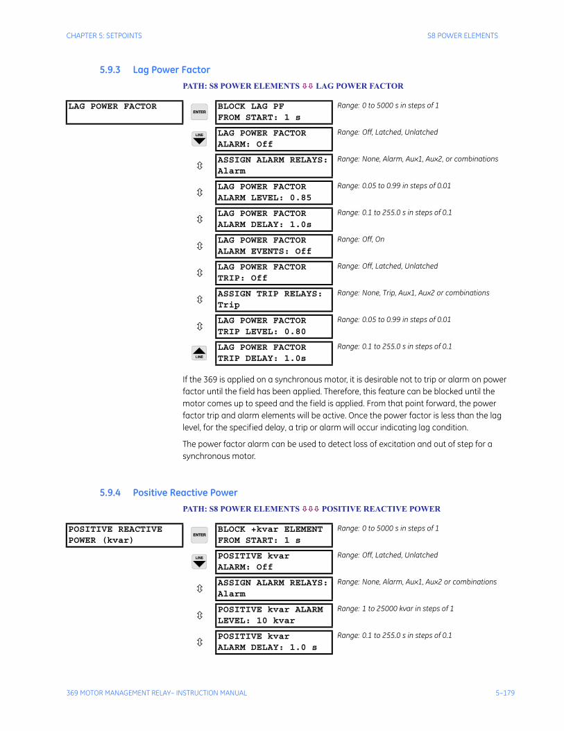
CHAPTER 5: SETPOINTS S8 POWER ELEMENTS
369 MOTOR MANAGEMENT RELAY– INSTRUCTION MANUAL 5–179
5.9.3 Lag Power FactorPATH: S8 POWER ELEMENTS LAG POWER FACTOR
If the 369 is applied on a synchronous motor, it is desirable not to trip or alarm on power factor until the field has been applied. Therefore, this feature can be blocked until the motor comes up to speed and the field is applied. From that point forward, the power factor trip and alarm elements will be active. Once the power factor is less than the lag level, for the specified delay, a trip or alarm will occur indicating lag condition.
The power factor alarm can be used to detect loss of excitation and out of step for a synchronous motor.
5.9.4 Positive Reactive PowerPATH: S8 POWER ELEMENTS POSITIVE REACTIVE POWER
LAG POWER FACTOR BLOCK LAG PFFROM START: 1 s
Range: 0 to 5000 s in steps of 1
LAG POWER FACTORALARM: Off
Range: Off, Latched, Unlatched
ASSIGN ALARM RELAYS:Alarm
Range: None, Alarm, Aux1, Aux2, or combinations
LAG POWER FACTORALARM LEVEL: 0.85
Range: 0.05 to 0.99 in steps of 0.01
LAG POWER FACTORALARM DELAY: 1.0s
Range: 0.1 to 255.0 s in steps of 0.1
LAG POWER FACTORALARM EVENTS: Off
Range: Off, On
LAG POWER FACTORTRIP: Off
Range: Off, Latched, Unlatched
ASSIGN TRIP RELAYS:Trip
Range: None, Trip, Aux1, Aux2 or combinations
LAG POWER FACTORTRIP LEVEL: 0.80
Range: 0.05 to 0.99 in steps of 0.01
LAG POWER FACTORTRIP DELAY: 1.0s
Range: 0.1 to 255.0 s in steps of 0.1
POSITIVE REACTIVEPOWER (kvar)
BLOCK +kvar ELEMENTFROM START: 1 s
Range: 0 to 5000 s in steps of 1
POSITIVE kvarALARM: Off
Range: Off, Latched, Unlatched
ASSIGN ALARM RELAYS:Alarm
Range: None, Alarm, Aux1, Aux2 or combinations
POSITIVE kvar ALARMLEVEL: 10 kvar
Range: 1 to 25000 kvar in steps of 1
POSITIVE kvarALARM DELAY: 1.0 s
Range: 0.1 to 255.0 s in steps of 0.1
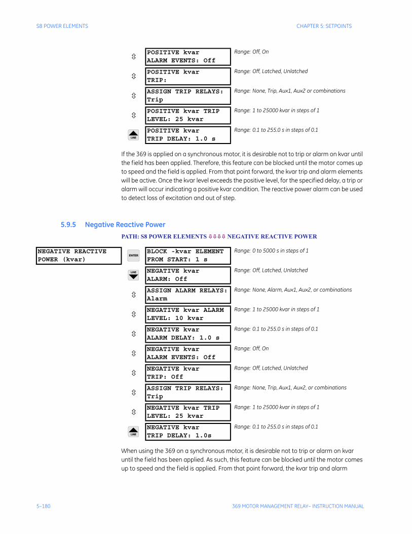
5–180 369 MOTOR MANAGEMENT RELAY– INSTRUCTION MANUAL
S8 POWER ELEMENTS CHAPTER 5: SETPOINTS
If the 369 is applied on a synchronous motor, it is desirable not to trip or alarm on kvar until the field has been applied. Therefore, this feature can be blocked until the motor comes up to speed and the field is applied. From that point forward, the kvar trip and alarm elements will be active. Once the kvar level exceeds the positive level, for the specified delay, a trip or alarm will occur indicating a positive kvar condition. The reactive power alarm can be used to detect loss of excitation and out of step.
5.9.5 Negative Reactive Power PATH: S8 POWER ELEMENTS NEGATIVE REACTIVE POWER
When using the 369 on a synchronous motor, it is desirable not to trip or alarm on kvar until the field has been applied. As such, this feature can be blocked until the motor comes up to speed and the field is applied. From that point forward, the kvar trip and alarm
POSITIVE kvarALARM EVENTS: Off
Range: Off, On
POSITIVE kvarTRIP:
Range: Off, Latched, Unlatched
ASSIGN TRIP RELAYS:Trip
Range: None, Trip, Aux1, Aux2 or combinations
POSITIVE kvar TRIPLEVEL: 25 kvar
Range: 1 to 25000 kvar in steps of 1
POSITIVE kvarTRIP DELAY: 1.0 s
Range: 0.1 to 255.0 s in steps of 0.1
NEGATIVE REACTIVEPOWER (kvar)
BLOCK -kvar ELEMENTFROM START: 1 s
Range: 0 to 5000 s in steps of 1
NEGATIVE kvarALARM: Off
Range: Off, Latched, Unlatched
ASSIGN ALARM RELAYS:Alarm
Range: None, Alarm, Aux1, Aux2, or combinations
NEGATIVE kvar ALARMLEVEL: 10 kvar
Range: 1 to 25000 kvar in steps of 1
NEGATIVE kvarALARM DELAY: 1.0 s
Range: 0.1 to 255.0 s in steps of 0.1
NEGATIVE kvarALARM EVENTS: Off
Range: Off, On
NEGATIVE kvarTRIP: Off
Range: Off, Latched, Unlatched
ASSIGN TRIP RELAYS:Trip
Range: None, Trip, Aux1, Aux2, or combinations
NEGATIVE kvar TRIPLEVEL: 25 kvar
Range: 1 to 25000 kvar in steps of 1
NEGATIVE kvarTRIP DELAY: 1.0s
Range: 0.1 to 255.0 s in steps of 0.1

CHAPTER 5: SETPOINTS S8 POWER ELEMENTS
369 MOTOR MANAGEMENT RELAY– INSTRUCTION MANUAL 5–181
elements will be active. Once the kvar level exceeds the negative level for the specified delay, a trip or alarm occurs, indicating a negative kvar condition. The reactive power alarm can be used to detect overexcitation or loss of load.
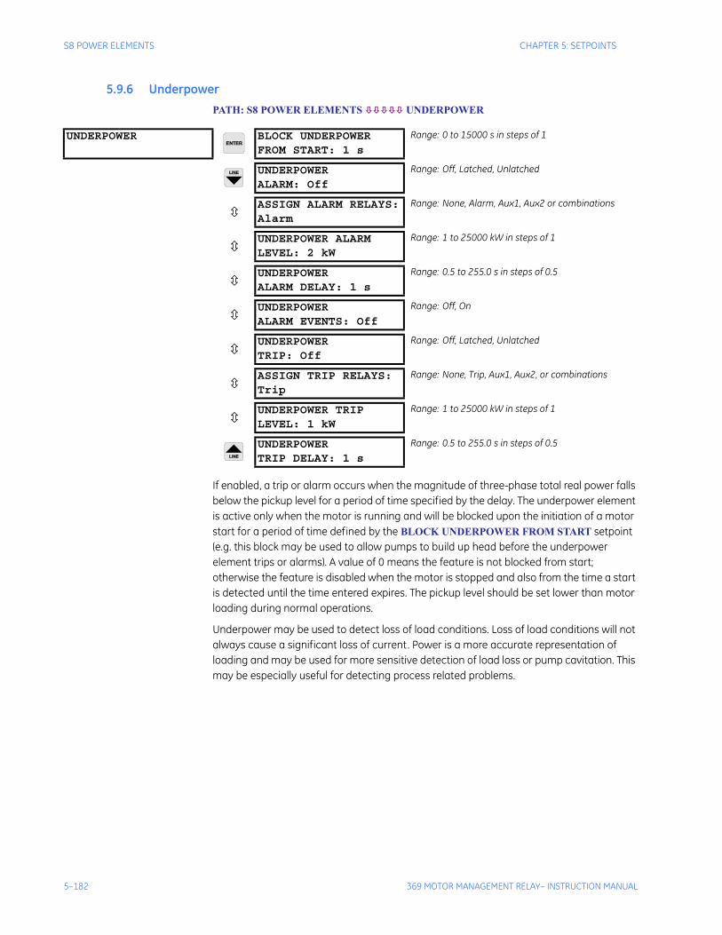
5–182 369 MOTOR MANAGEMENT RELAY– INSTRUCTION MANUAL
S8 POWER ELEMENTS CHAPTER 5: SETPOINTS
5.9.6 Underpower PATH: S8 POWER ELEMENTS UNDERPOWER
If enabled, a trip or alarm occurs when the magnitude of three-phase total real power falls below the pickup level for a period of time specified by the delay. The underpower element is active only when the motor is running and will be blocked upon the initiation of a motor start for a period of time defined by the BLOCK UNDERPOWER FROM START setpoint (e.g. this block may be used to allow pumps to build up head before the underpower element trips or alarms). A value of 0 means the feature is not blocked from start; otherwise the feature is disabled when the motor is stopped and also from the time a start is detected until the time entered expires. The pickup level should be set lower than motor loading during normal operations.
Underpower may be used to detect loss of load conditions. Loss of load conditions will not always cause a significant loss of current. Power is a more accurate representation of loading and may be used for more sensitive detection of load loss or pump cavitation. This may be especially useful for detecting process related problems.
UNDERPOWER BLOCK UNDERPOWERFROM START: 1 s
Range: 0 to 15000 s in steps of 1
UNDERPOWERALARM: Off
Range: Off, Latched, Unlatched
ASSIGN ALARM RELAYS:Alarm
Range: None, Alarm, Aux1, Aux2 or combinations
UNDERPOWER ALARMLEVEL: 2 kW
Range: 1 to 25000 kW in steps of 1
UNDERPOWERALARM DELAY: 1 s
Range: 0.5 to 255.0 s in steps of 0.5
UNDERPOWERALARM EVENTS: Off
Range: Off, On
UNDERPOWERTRIP: Off
Range: Off, Latched, Unlatched
ASSIGN TRIP RELAYS:Trip
Range: None, Trip, Aux1, Aux2, or combinations
UNDERPOWER TRIPLEVEL: 1 kW
Range: 1 to 25000 kW in steps of 1
UNDERPOWERTRIP DELAY: 1 s
Range: 0.5 to 255.0 s in steps of 0.5
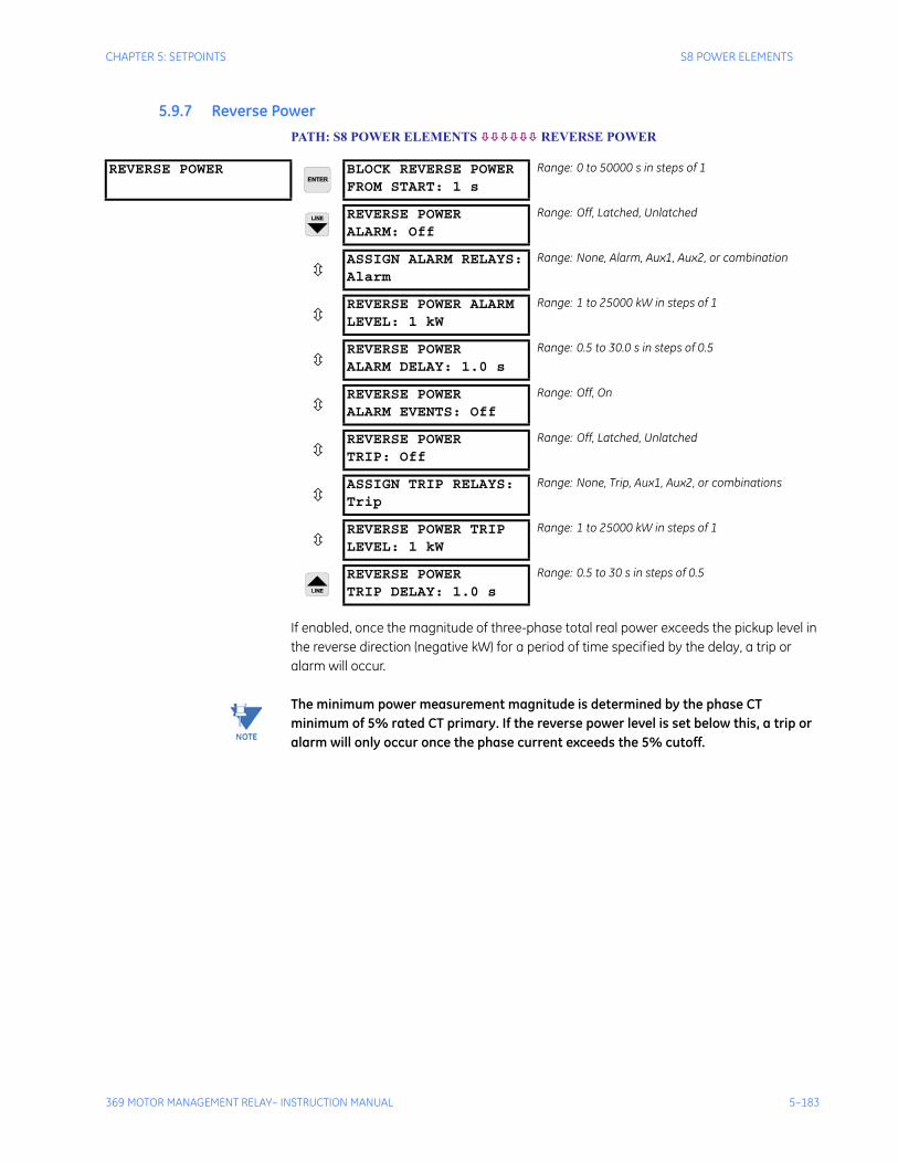
CHAPTER 5: SETPOINTS S8 POWER ELEMENTS
369 MOTOR MANAGEMENT RELAY– INSTRUCTION MANUAL 5–183
5.9.7 Reverse Power PATH: S8 POWER ELEMENTS REVERSE POWER
If enabled, once the magnitude of three-phase total real power exceeds the pickup level in the reverse direction (negative kW) for a period of time specified by the delay, a trip or alarm will occur.
Note The minimum power measurement magnitude is determined by the phase CT minimum of 5% rated CT primary. If the reverse power level is set below this, a trip or alarm will only occur once the phase current exceeds the 5% cutoff.
REVERSE POWER BLOCK REVERSE POWERFROM START: 1 s
Range: 0 to 50000 s in steps of 1
REVERSE POWERALARM: Off
Range: Off, Latched, Unlatched
ASSIGN ALARM RELAYS:Alarm
Range: None, Alarm, Aux1, Aux2, or combination
REVERSE POWER ALARMLEVEL: 1 kW
Range: 1 to 25000 kW in steps of 1
REVERSE POWERALARM DELAY: 1.0 s
Range: 0.5 to 30.0 s in steps of 0.5
REVERSE POWERALARM EVENTS: Off
Range: Off, On
REVERSE POWERTRIP: Off
Range: Off, Latched, Unlatched
ASSIGN TRIP RELAYS:Trip
Range: None, Trip, Aux1, Aux2, or combinations
REVERSE POWER TRIPLEVEL: 1 kW
Range: 1 to 25000 kW in steps of 1
REVERSE POWERTRIP DELAY: 1.0 s
Range: 0.5 to 30 s in steps of 0.5
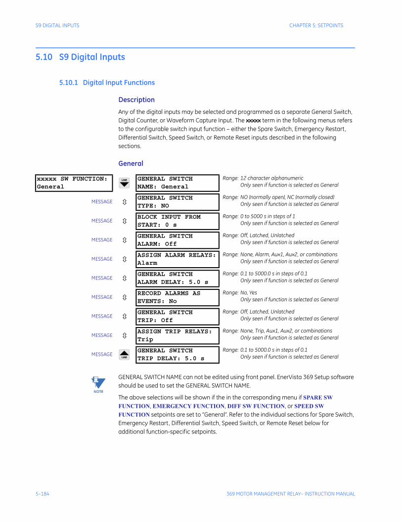
5–184 369 MOTOR MANAGEMENT RELAY– INSTRUCTION MANUAL
S9 DIGITAL INPUTS CHAPTER 5: SETPOINTS
5.10 S9 Digital Inputs
5.10.1 Digital Input Functions
Description
Any of the digital inputs may be selected and programmed as a separate General Switch, Digital Counter, or Waveform Capture Input. The xxxxx term in the following menus refers to the configurable switch input function – either the Spare Switch, Emergency Restart, Differential Switch, Speed Switch, or Remote Reset inputs described in the following sections.
General
Note GENERAL SWITCH NAME can not be edited using front panel. EnerVista 369 Setup software should be used to set the GENERAL SWITCH NAME.
The above selections will be shown if the in the corresponding menu if SPARE SW FUNCTION, EMERGENCY FUNCTION, DIFF SW FUNCTION, or SPEED SW FUNCTION setpoints are set to “General”. Refer to the individual sections for Spare Switch, Emergency Restart, Differential Switch, Speed Switch, or Remote Reset below for additional function-specific setpoints.
xxxxx SW FUNCTION:General
GENERAL SWITCHNAME: General
Range: 12 character alphanumericOnly seen if function is selected as General
MESSAGEGENERAL SWITCHTYPE: NO
Range: NO (normally open), NC (normally closed)Only seen if function is selected as General
MESSAGEBLOCK INPUT FROMSTART: 0 s
Range: 0 to 5000 s in steps of 1Only seen if function is selected as General
MESSAGEGENERAL SWITCHALARM: Off
Range: Off, Latched, UnlatchedOnly seen if function is selected as General
MESSAGEASSIGN ALARM RELAYS:Alarm
Range: None, Alarm, Aux1, Aux2, or combinationsOnly seen if function is selected as General
MESSAGEGENERAL SWITCHALARM DELAY: 5.0 s
Range: 0.1 to 5000.0 s in steps of 0.1Only seen if function is selected as General
MESSAGERECORD ALARMS ASEVENTS: No
Range: No, YesOnly seen if function is selected as General
MESSAGEGENERAL SWITCHTRIP: Off
Range: Off, Latched, UnlatchedOnly seen if function is selected as General
MESSAGEASSIGN TRIP RELAYS:Trip
Range: None, Trip, Aux1, Aux2, or combinationsOnly seen if function is selected as General
MESSAGEGENERAL SWITCHTRIP DELAY: 5.0 s
Range: 0.1 to 5000.0 s in steps of 0.1Only seen if function is selected as General
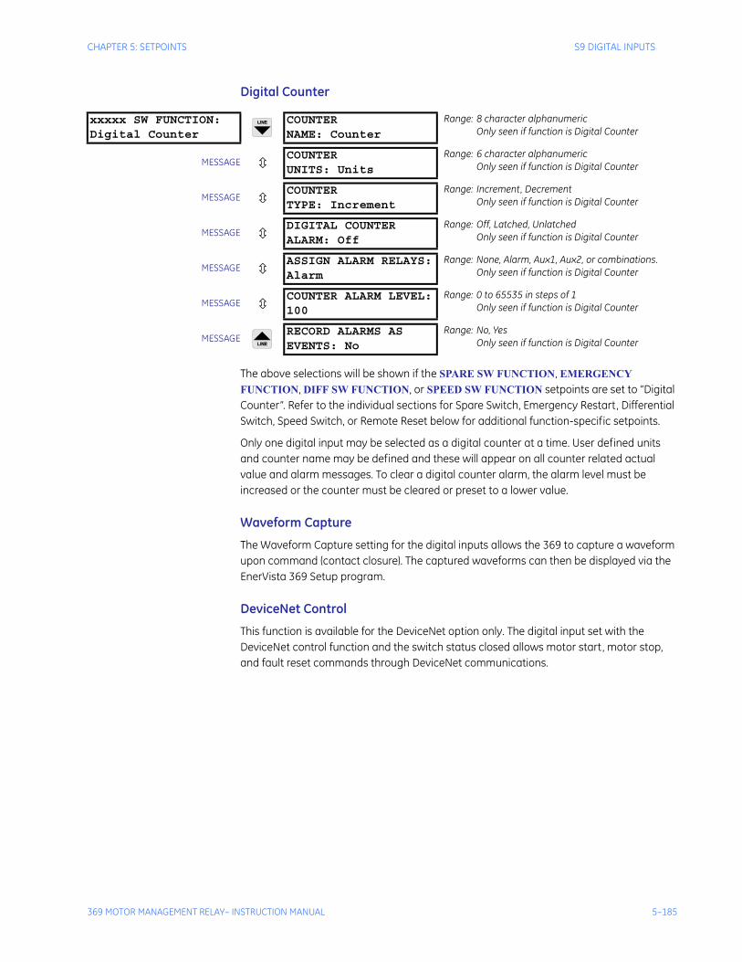
CHAPTER 5: SETPOINTS S9 DIGITAL INPUTS
369 MOTOR MANAGEMENT RELAY– INSTRUCTION MANUAL 5–185
Digital Counter
The above selections will be shown if the SPARE SW FUNCTION, EMERGENCY FUNCTION, DIFF SW FUNCTION, or SPEED SW FUNCTION setpoints are set to “Digital Counter”. Refer to the individual sections for Spare Switch, Emergency Restart, Differential Switch, Speed Switch, or Remote Reset below for additional function-specific setpoints.
Only one digital input may be selected as a digital counter at a time. User defined units and counter name may be defined and these will appear on all counter related actual value and alarm messages. To clear a digital counter alarm, the alarm level must be increased or the counter must be cleared or preset to a lower value.
Waveform Capture
The Waveform Capture setting for the digital inputs allows the 369 to capture a waveform upon command (contact closure). The captured waveforms can then be displayed via the EnerVista 369 Setup program.
DeviceNet Control
This function is available for the DeviceNet option only. The digital input set with the DeviceNet control function and the switch status closed allows motor start, motor stop, and fault reset commands through DeviceNet communications.
xxxxx SW FUNCTION:Digital Counter
COUNTERNAME: Counter
Range: 8 character alphanumericOnly seen if function is Digital Counter
MESSAGECOUNTERUNITS: Units
Range: 6 character alphanumericOnly seen if function is Digital Counter
MESSAGECOUNTERTYPE: Increment
Range: Increment, DecrementOnly seen if function is Digital Counter
MESSAGEDIGITAL COUNTERALARM: Off
Range: Off, Latched, UnlatchedOnly seen if function is Digital Counter
MESSAGEASSIGN ALARM RELAYS:Alarm
Range: None, Alarm, Aux1, Aux2, or combinations.Only seen if function is Digital Counter
MESSAGECOUNTER ALARM LEVEL:100
Range: 0 to 65535 in steps of 1Only seen if function is Digital Counter
MESSAGERECORD ALARMS ASEVENTS: No
Range: No, YesOnly seen if function is Digital Counter
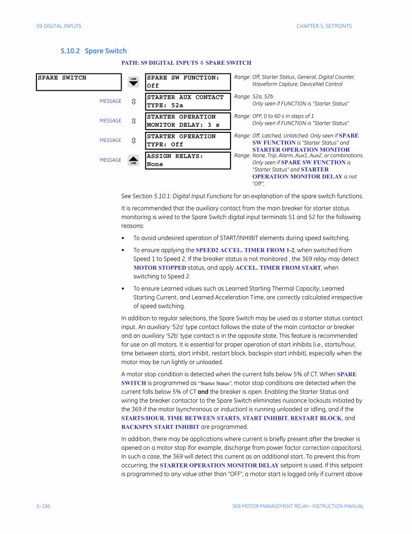
5–186 369 MOTOR MANAGEMENT RELAY– INSTRUCTION MANUAL
S9 DIGITAL INPUTS CHAPTER 5: SETPOINTS
5.10.2 Spare SwitchPATH: S9 DIGITAL INPUTS SPARE SWITCH
See Section 5.10.1: Digital Input Functions for an explanation of the spare switch functions.
It is recommended that the auxiliary contact from the main breaker for starter status monitoring is wired to the Spare Switch digital input terminals 51 and 52 for the following reasons:
• To avoid undesired operation of START/INHIBIT elements during speed switching.
• To ensure applying the SPEED2 ACCEL. TIMER FROM 1-2, when switched from Speed 1 to Speed 2. If the breaker status is not monitored , the 369 relay may detect MOTOR STOPPED status, and apply ACCEL. TIMER FROM START, when switching to Speed 2.
• To ensure Learned values such as Learned Starting Thermal Capacity, Learned Starting Current, and Learned Acceleration Time, are correctly calculated irrespective of speed switching.
In addition to regular selections, the Spare Switch may be used as a starter status contact input. An auxiliary ‘52a’ type contact follows the state of the main contactor or breaker and an auxiliary ‘52b’ type contact is in the opposite state. This feature is recommended for use on all motors. It is essential for proper operation of start inhibits (i.e., starts/hour, time between starts, start inhibit, restart block, backspin start inhibit), especially when the motor may be run lightly or unloaded.
A motor stop condition is detected when the current falls below 5% of CT. When SPARE SWITCH is programmed as “Starter Status”, motor stop conditions are detected when the current falls below 5% of CT and the breaker is open. Enabling the Starter Status and wiring the breaker contactor to the Spare Switch eliminates nuisance lockouts initiated by the 369 if the motor (synchronous or induction) is running unloaded or idling, and if the STARTS/HOUR, TIME BETWEEN STARTS, START INHIBIT, RESTART BLOCK, and BACKSPIN START INHIBIT are programmed.
In addition, there may be applications where current is briefly present after the breaker is opened on a motor stop (for example, discharge from power factor correction capacitors). In such a case, the 369 will detect this current as an additional start. To prevent this from occurring, the STARTER OPERATION MONITOR DELAY setpoint is used. If this setpoint is programmed to any value other than “OFF”, a motor start is logged only if current above
SPARE SWITCH SPARE SW FUNCTION:Off
Range: Off, Starter Status, General, Digital Counter, Waveform Capture, DeviceNet Control
MESSAGESTARTER AUX CONTACTTYPE: 52a
Range: 52a, 52bOnly seen if FUNCTION is "Starter Status"
MESSAGESTARTER OPERATIONMONITOR DELAY: 3 s
Range: OFF, 0 to 60 s in steps of 1Only seen if FUNCTION is “Starter Status”
MESSAGESTARTER OPERATIONTYPE: Off
Range: Off, Latched, Unlatched. Only seen if SPARE SW FUNCTION is “Starter Status” and STARTER OPERATION MONITOR
MESSAGEASSIGN RELAYS:None
Range: None, Trip, Alarm, Aux1, Aux2, or combinations.Only seen if SPARE SW FUNCTION is “Starter Status” and STARTER OPERATION MONITOR DELAY is not “Off”.
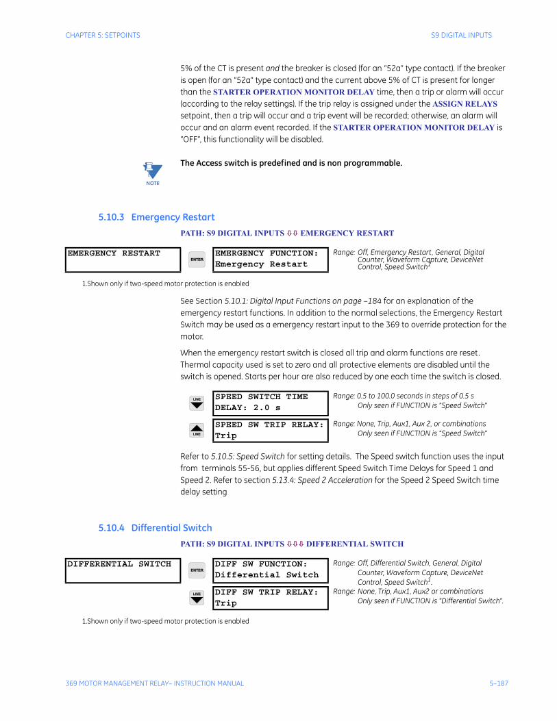
CHAPTER 5: SETPOINTS S9 DIGITAL INPUTS
369 MOTOR MANAGEMENT RELAY– INSTRUCTION MANUAL 5–187
5% of the CT is present and the breaker is closed (for an “52a” type contact). If the breaker is open (for an “52a” type contact) and the current above 5% of CT is present for longer than the STARTER OPERATION MONITOR DELAY time, then a trip or alarm will occur (according to the relay settings). If the trip relay is assigned under the ASSIGN RELAYS setpoint, then a trip will occur and a trip event will be recorded; otherwise, an alarm will occur and an alarm event recorded. If the STARTER OPERATION MONITOR DELAY is “OFF”, this functionality will be disabled.
Note The Access switch is predefined and is non programmable.
5.10.3 Emergency RestartPATH: S9 DIGITAL INPUTS EMERGENCY RESTART
See Section 5.10.1: Digital Input Functions on page –184 for an explanation of the emergency restart functions. In addition to the normal selections, the Emergency Restart Switch may be used as a emergency restart input to the 369 to override protection for the motor.
When the emergency restart switch is closed all trip and alarm functions are reset. Thermal capacity used is set to zero and all protective elements are disabled until the switch is opened. Starts per hour are also reduced by one each time the switch is closed.
Refer to 5.10.5: Speed Switch for setting details. The Speed switch function uses the input from terminals 55-56, but applies different Speed Switch Time Delays for Speed 1 and Speed 2. Refer to section 5.13.4: Speed 2 Acceleration for the Speed 2 Speed Switch time delay setting
5.10.4 Differential SwitchPATH: S9 DIGITAL INPUTS DIFFERENTIAL SWITCH
EMERGENCY RESTART EMERGENCY FUNCTION:Emergency Restart
Range: Off, Emergency Restart, General, Digital Counter, Waveform Capture, DeviceNet Control, Speed Switch1
1.Shown only if two-speed motor protection is enabled
SPEED SWITCH TIMEDELAY: 2.0 s
Range: 0.5 to 100.0 seconds in steps of 0.5 sOnly seen if FUNCTION is "Speed Switch"
SPEED SW TRIP RELAY:Trip
Range: None, Trip, Aux1, Aux 2, or combinationsOnly seen if FUNCTION is "Speed Switch"
DIFFERENTIAL SWITCH DIFF SW FUNCTION:Differential Switch
Range: Off, Differential Switch, General, Digital Counter, Waveform Capture, DeviceNet Control, Speed Switch1.
DIFF SW TRIP RELAY:Trip
Range: None, Trip, Aux1, Aux2 or combinationsOnly seen if FUNCTION is "Differential Switch".
1.Shown only if two-speed motor protection is enabled
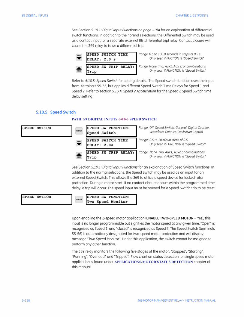
5–188 369 MOTOR MANAGEMENT RELAY– INSTRUCTION MANUAL
S9 DIGITAL INPUTS CHAPTER 5: SETPOINTS
See Section 5.10.1: Digital Input Functions on page –184 for an explanation of differential switch functions. In addition to the normal selections, the Differential Switch may be used as a contact input for a separate external 86 (differential trip) relay. Contact closure will cause the 369 relay to issue a differential trip.
Refer to 5.10.5: Speed Switch for setting details. The Speed switch function uses the input from terminals 55-56, but applies different Speed Switch Time Delays for Speed 1 and Speed 2. Refer to section 5.13.4: Speed 2 Acceleration for the Speed 2 Speed Switch time delay setting
5.10.5 Speed SwitchPATH: S9 DIGITAL INPUTS SPEED SWITCH
See Section 5.10.1: Digital Input Functions for an explanation of Speed Switch functions. In addition to the normal selections, the Speed Switch may be used as an input for an external Speed Switch. This allows the 369 to utilize a speed device for locked rotor protection. During a motor start, if no contact closure occurs within the programmed time delay, a trip will occur. The speed input must be opened for a Speed Switch trip to be reset
.
Upon enabling the 2-speed motor application (ENABLE TWO-SPEED MOTOR = Yes), this input is no longer programmable but signifies the motor speed at any given time. “Open” is recognized as Speed 1, and “closed” is recognized as Speed 2. The Speed Switch (terminals 55-56) is automatically designated for two-speed motor protection and will display message “Two Speed Monitor”. Under this application, the switch cannot be assigned to perform any other function.
The 369 relay monitors the following five stages of the motor: “Stopped”, “Starting”, “Running”, “Overload”, and “Tripped”. Flow chart on status detection for single speed motor application is found under APPLICATIONS/MOTOR STATUS DETECTION chapter of this manual.
SPEED SWITCH TIMEDELAY: 2.0 s
Range: 0.5 to 100.0 seconds in steps of 0.5 sOnly seen if FUCTION is "Speed Switch"
SPEED SW TRIP RELAY:Trip
Range: None, Trip, Aux1, Aux 2, or combinationsOnly seen if FUNCTION is "Speed Switch"
SPEED SWITCH SPEED SW FUNCTION:Speed Switch
Range: Off, Speed Switch, General, Digital Counter, Waveform Capture, DeviceNet Control
SPEED SWITCH TIMEDELAY: 2.0s
Range: 0.5 to 100.0s in steps of 0.5Only seen if FUNCTION is "Speed Switch"
SPEED SW TRIP RELAY:Trip
Range: None, Trip, Aux1, Aux2 or combinationsOnly seen if FUNCTION is "Speed Switch"
SPEED SWITCH SPEED SW FUNCTION:Two Speed Monitor
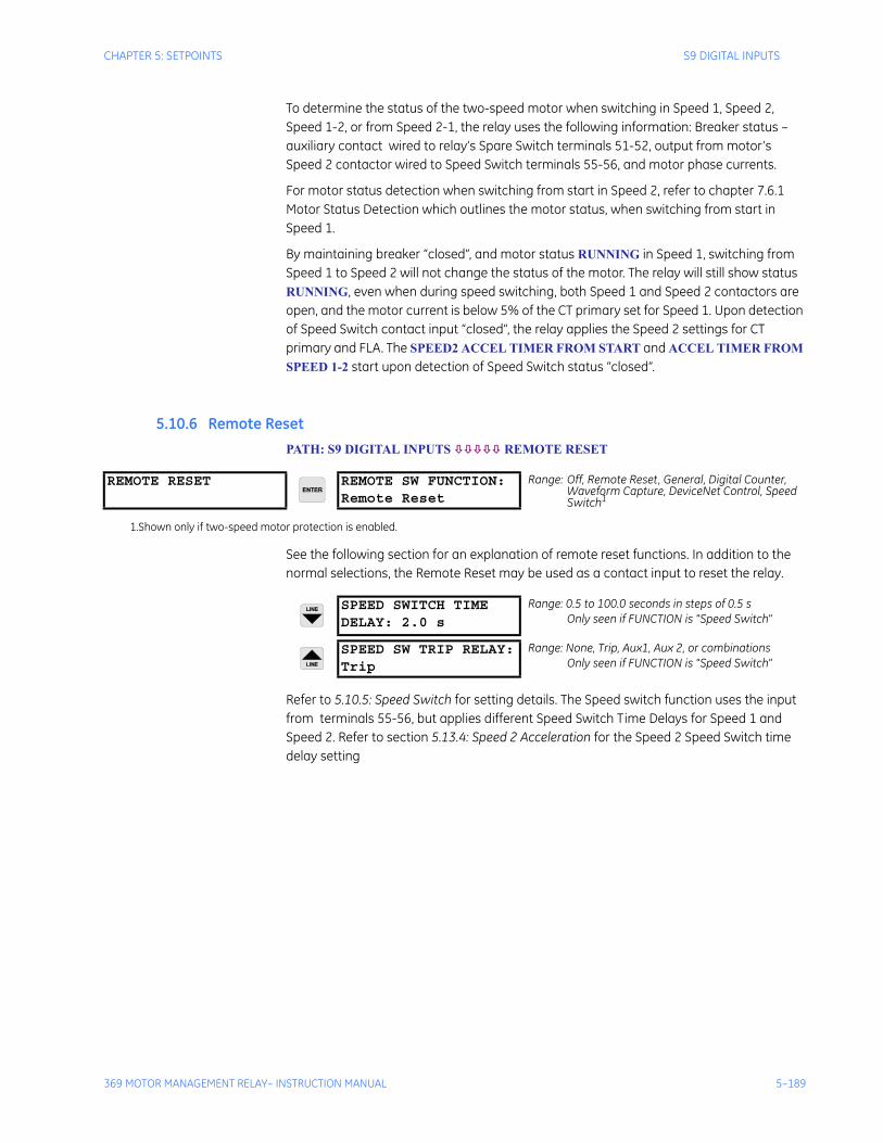
CHAPTER 5: SETPOINTS S9 DIGITAL INPUTS
369 MOTOR MANAGEMENT RELAY– INSTRUCTION MANUAL 5–189
To determine the status of the two-speed motor when switching in Speed 1, Speed 2, Speed 1-2, or from Speed 2-1, the relay uses the following information: Breaker status – auxiliary contact wired to relay’s Spare Switch terminals 51-52, output from motor’s Speed 2 contactor wired to Speed Switch terminals 55-56, and motor phase currents.
For motor status detection when switching from start in Speed 2, refer to chapter 7.6.1 Motor Status Detection which outlines the motor status, when switching from start in Speed 1.
By maintaining breaker “closed”, and motor status RUNNING in Speed 1, switching from Speed 1 to Speed 2 will not change the status of the motor. The relay will still show status RUNNING, even when during speed switching, both Speed 1 and Speed 2 contactors are open, and the motor current is below 5% of the CT primary set for Speed 1. Upon detection of Speed Switch contact input “closed”, the relay applies the Speed 2 settings for CT primary and FLA. The SPEED2 ACCEL TIMER FROM START and ACCEL TIMER FROM SPEED 1-2 start upon detection of Speed Switch status “closed”.
5.10.6 Remote ResetPATH: S9 DIGITAL INPUTS REMOTE RESET
See the following section for an explanation of remote reset functions. In addition to the normal selections, the Remote Reset may be used as a contact input to reset the relay.
Refer to 5.10.5: Speed Switch for setting details. The Speed switch function uses the input from terminals 55-56, but applies different Speed Switch Time Delays for Speed 1 and Speed 2. Refer to section 5.13.4: Speed 2 Acceleration for the Speed 2 Speed Switch time delay setting
REMOTE RESET REMOTE SW FUNCTION:Remote Reset
Range: Off, Remote Reset, General, Digital Counter, Waveform Capture, DeviceNet Control, Speed Switch1
1.Shown only if two-speed motor protection is enabled.
SPEED SWITCH TIMEDELAY: 2.0 s
Range: 0.5 to 100.0 seconds in steps of 0.5 sOnly seen if FUNCTION is "Speed Switch"
SPEED SW TRIP RELAY:Trip
Range: None, Trip, Aux1, Aux 2, or combinationsOnly seen if FUNCTION is "Speed Switch"
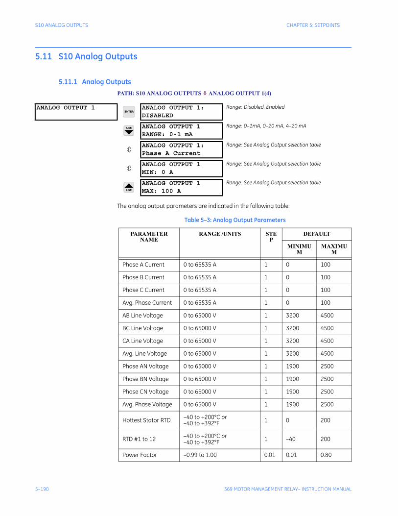
5–190 369 MOTOR MANAGEMENT RELAY– INSTRUCTION MANUAL
S10 ANALOG OUTPUTS CHAPTER 5: SETPOINTS
5.11 S10 Analog Outputs
5.11.1 Analog OutputsPATH: S10 ANALOG OUTPUTS ANALOG OUTPUT 1(4)
The analog output parameters are indicated in the following table:
ANALOG OUTPUT 1 ANALOG OUTPUT 1:DISABLED
Range: Disabled, Enabled
ANALOG OUTPUT 1RANGE: 0-1 mA
Range: 0–1mA, 0–20 mA, 4–20 mA
ANALOG OUTPUT 1:Phase A Current
Range: See Analog Output selection table
ANALOG OUTPUT 1MIN: 0 A
Range: See Analog Output selection table
ANALOG OUTPUT 1MAX: 100 A
Range: See Analog Output selection table
Table 5–3: Analog Output Parameters
PARAMETER NAME
RANGE /UNITS STEP
DEFAULT
MINIMUM
MAXIMUM
Phase A Current 0 to 65535 A 1 0 100
Phase B Current 0 to 65535 A 1 0 100
Phase C Current 0 to 65535 A 1 0 100
Avg. Phase Current 0 to 65535 A 1 0 100
AB Line Voltage 0 to 65000 V 1 3200 4500
BC Line Voltage 0 to 65000 V 1 3200 4500
CA Line Voltage 0 to 65000 V 1 3200 4500
Avg. Line Voltage 0 to 65000 V 1 3200 4500
Phase AN Voltage 0 to 65000 V 1 1900 2500
Phase BN Voltage 0 to 65000 V 1 1900 2500
Phase CN Voltage 0 to 65000 V 1 1900 2500
Avg. Phase Voltage 0 to 65000 V 1 1900 2500
Hottest Stator RTD –40 to +200°C or –40 to +392°F 1 0 200
RTD #1 to 12 –40 to +200°C or –40 to +392°F 1 –40 200
Power Factor –0.99 to 1.00 0.01 0.01 0.80
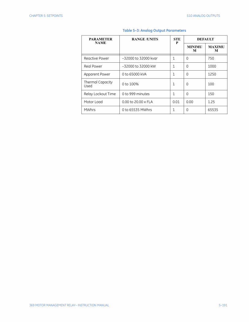
CHAPTER 5: SETPOINTS S10 ANALOG OUTPUTS
369 MOTOR MANAGEMENT RELAY– INSTRUCTION MANUAL 5–191
Reactive Power –32000 to 32000 kvar 1 0 750
Real Power –32000 to 32000 kW 1 0 1000
Apparent Power 0 to 65000 kVA 1 0 1250
Thermal Capacity Used 0 to 100% 1 0 100
Relay Lockout Time 0 to 999 minutes 1 0 150
Motor Load 0.00 to 20.00 x FLA 0.01 0.00 1.25
MWhrs 0 to 65535 MWhrs 1 0 65535
Table 5–3: Analog Output Parameters
PARAMETER NAME
RANGE /UNITS STEP
DEFAULT
MINIMUM
MAXIMUM
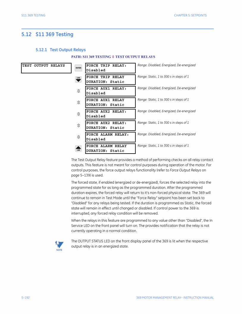
5–192 369 MOTOR MANAGEMENT RELAY– INSTRUCTION MANUAL
S11 369 TESTING CHAPTER 5: SETPOINTS
5.12 S11 369 Testing
5.12.1 Test Output RelaysPATH: S11 369 TESTING TEST OUTPUT RELAYS
The Test Output Relay feature provides a method of performing checks on all relay contact outputs. This feature is not meant for control purposes during operation of the motor. For control purposes, the force output relays functionality (refer to Force Output Relays on page 5–139) is used.
The forced state, if enabled (energized or de-energized), forces the selected relay into the programmed state for as long as the programmed duration. After the programmed duration expires, the forced relay will return to it's non-forced physical state. The 369 will continue to remain in Test Mode until the "Force Relay" setpoint has been set back to "Disabled" for any relays being tested. If the duration is programmed as Static, the forced state will remain in effect until changed or disabled. If control power to the 369 is interrupted, any forced relay condition will be removed.
When the relays in this feature are programmed to any value other than “Disabled”, the In Service LED on the front panel will turn on. The provides notification that the relay is not currently operating in a normal condition.
Note The OUTPUT STATUS LED on the front display panel of the 369 is lit when the respective output relay is in an energized state.
TEST OUTPUT RELAYS FORCE TRIP RELAY:Disabled
Range: Disabled, Energized, De-energized
FORCE TRIP RELAYDURATION: Static
Range: Static, 1 to 300 s in steps of 1
FORCE AUX1 RELAY:Disabled
Range: Disabled, Energized, De-energized
FORCE AUX1 RELAYDURATION: Static
Range: Static, 1 to 300 s in steps of 1
FORCE AUX2 RELAY:Disabled
Range: Disabled, Energized, De-energized
FORCE AUX2 RELAY:DURATION: Static
Range: Static, 1 to 300 s in steps of 1
FORCE ALARM RELAY:Disabled
Range: Disabled, Energized, De-energized
FORCE ALARM RELAYDURATION: Static
Range: Static, 1 to 300 s in steps of 1
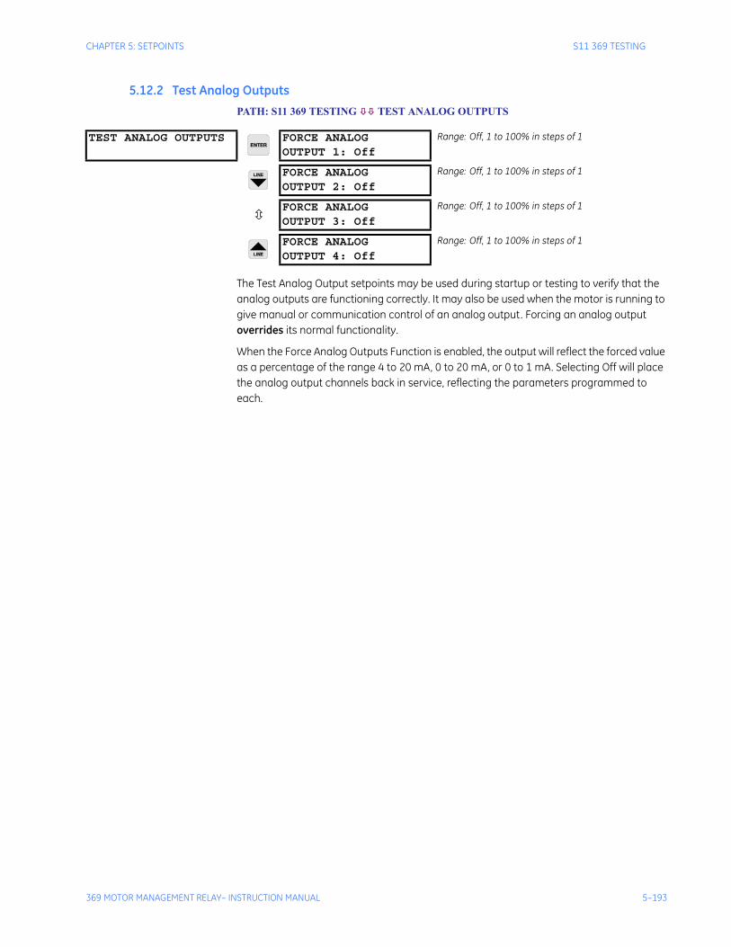
CHAPTER 5: SETPOINTS S11 369 TESTING
369 MOTOR MANAGEMENT RELAY– INSTRUCTION MANUAL 5–193
5.12.2 Test Analog OutputsPATH: S11 369 TESTING TEST ANALOG OUTPUTS
The Test Analog Output setpoints may be used during startup or testing to verify that the analog outputs are functioning correctly. It may also be used when the motor is running to give manual or communication control of an analog output. Forcing an analog output overrides its normal functionality.
When the Force Analog Outputs Function is enabled, the output will reflect the forced value as a percentage of the range 4 to 20 mA, 0 to 20 mA, or 0 to 1 mA. Selecting Off will place the analog output channels back in service, reflecting the parameters programmed to each.
TEST ANALOG OUTPUTS FORCE ANALOGOUTPUT 1: Off
Range: Off, 1 to 100% in steps of 1
FORCE ANALOGOUTPUT 2: Off
Range: Off, 1 to 100% in steps of 1
FORCE ANALOGOUTPUT 3: Off
Range: Off, 1 to 100% in steps of 1
FORCE ANALOGOUTPUT 4: Off
Range: Off, 1 to 100% in steps of 1
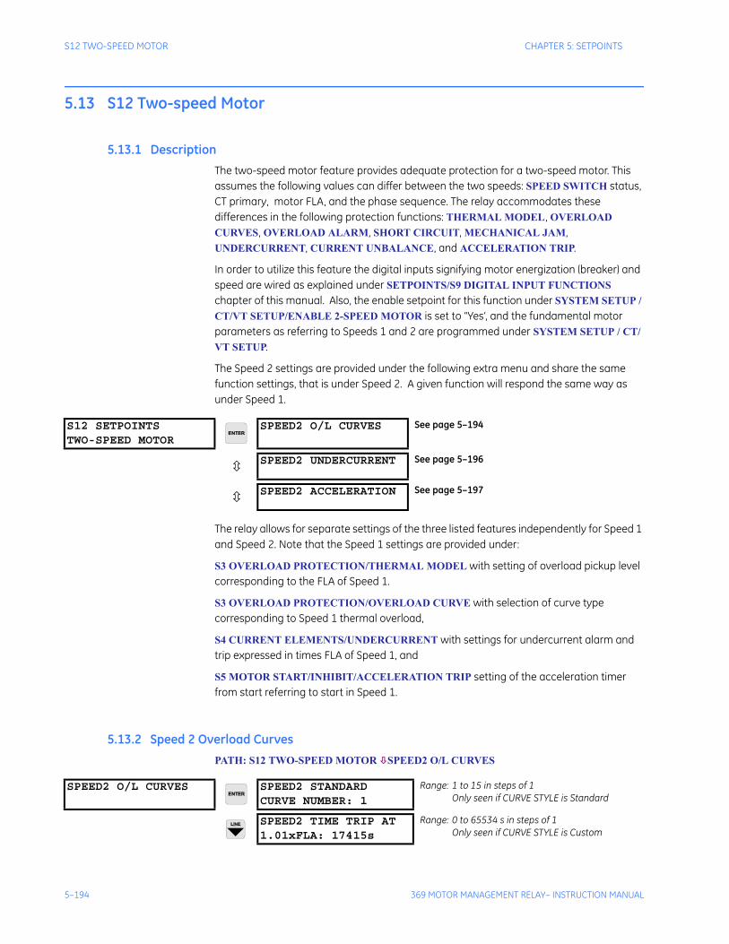
5–194 369 MOTOR MANAGEMENT RELAY– INSTRUCTION MANUAL
S12 TWO-SPEED MOTOR CHAPTER 5: SETPOINTS
5.13 S12 Two-speed Motor
5.13.1 DescriptionThe two-speed motor feature provides adequate protection for a two-speed motor. This assumes the following values can differ between the two speeds: SPEED SWITCH status, CT primary, motor FLA, and the phase sequence. The relay accommodates these differences in the following protection functions: THERMAL MODEL, OVERLOAD CURVES, OVERLOAD ALARM, SHORT CIRCUIT, MECHANICAL JAM, UNDERCURRENT, CURRENT UNBALANCE, and ACCELERATION TRIP.
In order to utilize this feature the digital inputs signifying motor energization (breaker) and speed are wired as explained under SETPOINTS/S9 DIGITAL INPUT FUNCTIONS chapter of this manual. Also, the enable setpoint for this function under SYSTEM SETUP / CT/VT SETUP/ENABLE 2-SPEED MOTOR is set to “Yes’, and the fundamental motor parameters as referring to Speeds 1 and 2 are programmed under SYSTEM SETUP / CT/VT SETUP.
The Speed 2 settings are provided under the following extra menu and share the same function settings, that is under Speed 2. A given function will respond the same way as under Speed 1.
The relay allows for separate settings of the three listed features independently for Speed 1 and Speed 2. Note that the Speed 1 settings are provided under:
S3 OVERLOAD PROTECTION/THERMAL MODEL with setting of overload pickup level corresponding to the FLA of Speed 1.
S3 OVERLOAD PROTECTION/OVERLOAD CURVE with selection of curve type corresponding to Speed 1 thermal overload,
S4 CURRENT ELEMENTS/UNDERCURRENT with settings for undercurrent alarm and trip expressed in times FLA of Speed 1, and
S5 MOTOR START/INHIBIT/ACCELERATION TRIP setting of the acceleration timer from start referring to start in Speed 1.
5.13.2 Speed 2 Overload CurvesPATH: S12 TWO-SPEED MOTOR SPEED2 O/L CURVES
S12 SETPOINTSTWO-SPEED MOTOR
SPEED2 O/L CURVES See page 5–194
SPEED2 UNDERCURRENT See page 5–196
SPEED2 ACCELERATION See page 5–197
SPEED2 O/L CURVES SPEED2 STANDARDCURVE NUMBER: 1
Range: 1 to 15 in steps of 1Only seen if CURVE STYLE is Standard
SPEED2 TIME TRIP AT1.01xFLA: 17415s
Range: 0 to 65534 s in steps of 1Only seen if CURVE STYLE is Custom
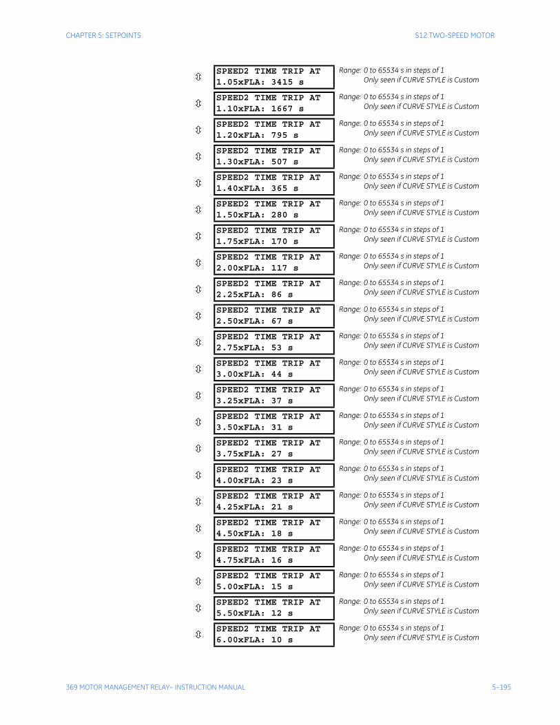
CHAPTER 5: SETPOINTS S12 TWO-SPEED MOTOR
369 MOTOR MANAGEMENT RELAY– INSTRUCTION MANUAL 5–195
SPEED2 TIME TRIP AT1.05xFLA: 3415 s
Range: 0 to 65534 s in steps of 1Only seen if CURVE STYLE is Custom
SPEED2 TIME TRIP AT1.10xFLA: 1667 s
Range: 0 to 65534 s in steps of 1Only seen if CURVE STYLE is Custom
SPEED2 TIME TRIP AT1.20xFLA: 795 s
Range: 0 to 65534 s in steps of 1Only seen if CURVE STYLE is Custom
SPEED2 TIME TRIP AT1.30xFLA: 507 s
Range: 0 to 65534 s in steps of 1Only seen if CURVE STYLE is Custom
SPEED2 TIME TRIP AT1.40xFLA: 365 s
Range: 0 to 65534 s in steps of 1Only seen if CURVE STYLE is Custom
SPEED2 TIME TRIP AT1.50xFLA: 280 s
Range: 0 to 65534 s in steps of 1Only seen if CURVE STYLE is Custom
SPEED2 TIME TRIP AT1.75xFLA: 170 s
Range: 0 to 65534 s in steps of 1Only seen if CURVE STYLE is Custom
SPEED2 TIME TRIP AT2.00xFLA: 117 s
Range: 0 to 65534 s in steps of 1Only seen if CURVE STYLE is Custom
SPEED2 TIME TRIP AT2.25xFLA: 86 s
Range: 0 to 65534 s in steps of 1Only seen if CURVE STYLE is Custom
SPEED2 TIME TRIP AT2.50xFLA: 67 s
Range: 0 to 65534 s in steps of 1Only seen if CURVE STYLE is Custom
SPEED2 TIME TRIP AT2.75xFLA: 53 s
Range: 0 to 65534 s in steps of 1Only seen if CURVE STYLE is Custom
SPEED2 TIME TRIP AT3.00xFLA: 44 s
Range: 0 to 65534 s in steps of 1Only seen if CURVE STYLE is Custom
SPEED2 TIME TRIP AT3.25xFLA: 37 s
Range: 0 to 65534 s in steps of 1Only seen if CURVE STYLE is Custom
SPEED2 TIME TRIP AT3.50xFLA: 31 s
Range: 0 to 65534 s in steps of 1Only seen if CURVE STYLE is Custom
SPEED2 TIME TRIP AT3.75xFLA: 27 s
Range: 0 to 65534 s in steps of 1Only seen if CURVE STYLE is Custom
SPEED2 TIME TRIP AT4.00xFLA: 23 s
Range: 0 to 65534 s in steps of 1Only seen if CURVE STYLE is Custom
SPEED2 TIME TRIP AT4.25xFLA: 21 s
Range: 0 to 65534 s in steps of 1Only seen if CURVE STYLE is Custom
SPEED2 TIME TRIP AT4.50xFLA: 18 s
Range: 0 to 65534 s in steps of 1Only seen if CURVE STYLE is Custom
SPEED2 TIME TRIP AT4.75xFLA: 16 s
Range: 0 to 65534 s in steps of 1Only seen if CURVE STYLE is Custom
SPEED2 TIME TRIP AT5.00xFLA: 15 s
Range: 0 to 65534 s in steps of 1Only seen if CURVE STYLE is Custom
SPEED2 TIME TRIP AT5.50xFLA: 12 s
Range: 0 to 65534 s in steps of 1Only seen if CURVE STYLE is Custom
SPEED2 TIME TRIP AT6.00xFLA: 10 s
Range: 0 to 65534 s in steps of 1Only seen if CURVE STYLE is Custom
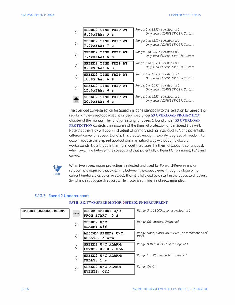
5–196 369 MOTOR MANAGEMENT RELAY– INSTRUCTION MANUAL
S12 TWO-SPEED MOTOR CHAPTER 5: SETPOINTS
The overload curve selection for Speed 2 is done identically to the selection for Speed 1 or regular single-speed applications as described under S3 OVERLOAD PROTECTION chapter of the manual. The function setting for Speed 1 found under S3 OVERLOAD PROTECTION controls the response of the thermal protection under Speed 2 as well. Note that the relay will apply individual CT primary setting, individual FLA and potentially different curve for Speeds 1 and 2. This creates enough flexibility (degrees of freedom) to accommodate the 2-speed applications in a natural way without an awkward workarounds. Note that the thermal model integrates the thermal capacity continuously when switching between the speeds and thus potentially different CT primaries, FLAs and curves.
Note When two speed motor protection is selected and used for Forward/Reverse motor rotation, it is required that switching between the speeds goes through a stage of no current (motor slows down or stops). Then it is followed by a start in the opposite direction. Switching in opposite direction, while motor is running is not recommended.
5.13.3 Speed 2 UndercurrentPATH: S12 TWO-SPEED MOTOR SPEED2 UNDERCURRENT
SPEED2 TIME TRIP AT6.50xFLA: 9 s
Range: 0 to 65534 s in steps of 1Only seen if CURVE STYLE is Custom
SPEED2 TIME TRIP AT7.00xFLA: 7 s
Range: 0 to 65534 s in steps of 1Only seen if CURVE STYLE is Custom
SPEED2 TIME TRIP AT7.50xFLA: 6 s
Range: 0 to 65534 s in steps of 1Only seen if CURVE STYLE is Custom
SPEED2 TIME TRIP AT8.00xFLA: 6 S
Range: 0 to 65534 s in steps of 1Only seen if CURVE STYLE is Custom
SPEED2 TIME TRIP AT10.0xFLA: 6 s
Range: 0 to 65534 s in steps of 1Only seen if CURVE STYLE is Custom
SPEED2 TIME TRIP AT15.0xFLA: 6 s
Range: 0 to 65534 s in steps of 1Only seen if CURVE STYLE is Custom
SPEED2 TIME TRIP AT20.0xFLA: 6 s
Range: 0 to 65534 s in steps of 1Only seen if CURVE STYLE is Custom
SPEED2 UNDERCURRENT BLOCK SPEED2 U/C FROM START: 0 S
Range: 0 to 15000 seconds in steps of 1
SPEED2 U/C ALARM: Off
Range: Off, Latched, Unlatched
ASSIGN SPEED2 U/C RELAYS: Alarm
Range: None, Alarm, Aux1, Aux2, or combinations of them
SPEED2 U/C ALARM: LEVEL: 0.70 x FLA
Range: 0.10 to 0.99 x FLA in steps of 1
SPEED2 U/C ALARM: DELAY: 1 s
Range: 1 to 255 seconds in steps of 1
SPEED2 U/C ALARMEVENTS: Off
Range: On, Off
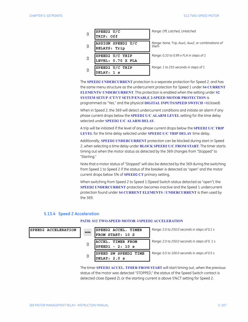
CHAPTER 5: SETPOINTS S12 TWO-SPEED MOTOR
369 MOTOR MANAGEMENT RELAY– INSTRUCTION MANUAL 5–197
The SPEED2 UNDERCURRENT protection is a separate protection for Speed 2, and has the same menu structure as the undercurrent protection for Speed 1 under S4 CURRENT ELEMENTS/ UNDERCURRENT. This protection is enabled when the setting under S2 SYSTEM SETUP /CT/VT SETUP/ENABLE 2-SPEED MOTOR PROTECTION is programmed as “Yes,” and the physical DIGITAL INPUTS/SPEED SWITCH =1(closed).
When in Speed 2, the 369 will detect undercurrent conditions and initiate an alarm if any phase current drops below the SPEED2 U/C ALARM LEVEL setting for the time delay selected under SPEED2 U/C ALARM DELAY.
A trip will be initiated if the level of any phase current drops below the SPEED2 U/C TRIP LEVEL for the time delay selected under SPEED2 U/C TRIP DELAY time delay.
Additionally, SPEED2 UNDERCURRENT protection can be blocked during start in Speed 2, when selecting a time delay under BLOCK SPEED2 U/C FROM START. The timer starts timing out when the motor status as detected by the 369 changes from "Stopped" to "Starting."
Note that a motor status of “Stopped” will also be detected by the 369 during the switching from Speed 1 to Speed 2 if the status of the breaker is detected as “open” and the motor current drops below 5% of SPEED2 CT primary setting.
When switching from Speed 2 to Speed 1 (Speed Switch status detected as “open”), the SPEED2 UNDERCURRENT protection becomes inactive and the Speed 1 undercurrent protection found under S4 CURRENT ELEMENTS / UNDERCURRENT is then used by the 369.
5.13.4 Speed 2 AccelerationPATH: S12 TWO-SPEED MOTOR SPEED2 ACCELERATION
The timer SPEED2 ACCEL. TIMER FROM START will start timing out, when the previous status of the motor was detected “STOPPED," the status of the Speed Switch contact is detected close (Speed 2), or the starting current is above 5%CT setting for Speed 2.
SPEED2 U/C TRIP: Off
Range: Off, Latched, Unlatched
ASSIGN SPEED2 U/C RELAYS: Trip
Range: None, Trip, Aux1, Aux2, or combinations of them
SPEED2 U/C TRIPLEVEL: 0.70 X FLA
Range: 0.10 to 0.99 x FLA in steps of 1
SPEED2 U/C TRIPDELAY: 1 s
Range: 1 to 255 seconds in steps of 1
SPEED2 ACCELERATION SPEED2 ACCEL. TIMER FROM START: 10 S
Range: 2.0 to 250.0 seconds in steps of 0.1 s
ACCEL. TIMER FROMSPEED1 - 2: 10 s
Range: 2.0 to 250.0 seconds in steps of 0. 1 s
SPEED SW SPEED2 TIMEDELAY: 2.0 s
Range: 0.5 to 100.0 seconds in steps of 0.5 s

5–198 369 MOTOR MANAGEMENT RELAY– INSTRUCTION MANUAL
S12 TWO-SPEED MOTOR CHAPTER 5: SETPOINTS
The timer ACCEL. TIMER FROM SPEED1-2 will start timing out, when the previous status of the motor was detected “RUNNING”, or “OVERLOAD”, and the Speed Switch contact is detected closed (Speed 2),
The 369 relay will ignore any Mechanical Jam during the transition from Speed 1 to Speed 2, until the motor current drops below Speed 2 Overload PKP setting, or during the time of Speed1-2 acceleration timer. At that point the Mechanical Jam feature will be enabled with Speed 2 FLA.
When using the Two Speed Motor feature in a Forward/Reverse motor rotation application, switching between speeds will result in a state with no current (motor slows down to a stop) followed by a start in the opposite direction. In this application, the ACCEL. TIMER FROM SPEED1-2 could be programmed with the same value as SPEED2 ACCEL. TIMER FROM START.
The SPEED SW SPEED2 TIME DELAY setting is available only if the “SPEED SWITCH” function is assigned to one of the DIGITAL INPUTS under setpoints S9 DIGITAL INPUTS.
SPEED2 ACCEL. TIMER FROM START and ACCEL. TIMER FROM SPEED1-2 become functional only if the acceleration time at Speed 1 (see S5 section 5.6.2: Acceleration Trip) is enabled.
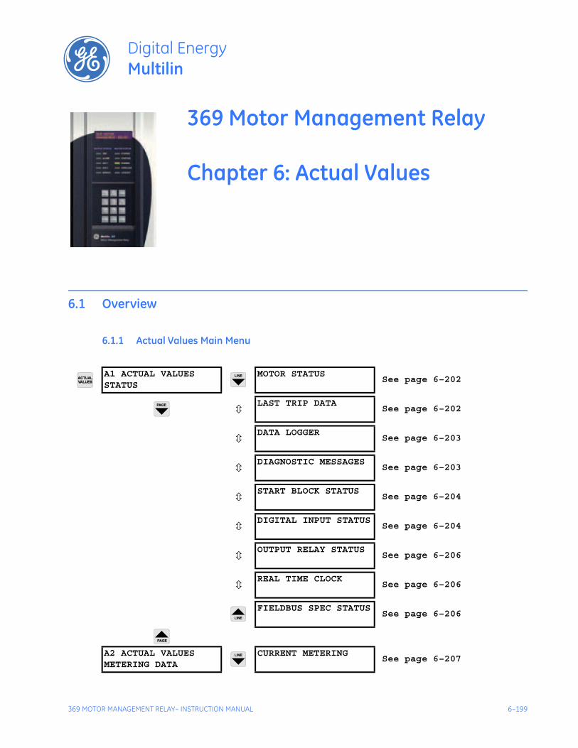
369 MOTOR MANAGEMENT RELAY– INSTRUCTION MANUAL 6–199
369 Motor Management Relay
Chapter 6: Actual Values
Digital EnergyMultilin
Actual Values
6.1 Overview
6.1.1 Actual Values Main Menu
A1 ACTUAL VALUESSTATUS
MOTOR STATUSSee page 6–202
LAST TRIP DATASee page 6–202
DATA LOGGERSee page 6–203
DIAGNOSTIC MESSAGESSee page 6–203
START BLOCK STATUSSee page 6–204
DIGITAL INPUT STATUSSee page 6–204
OUTPUT RELAY STATUSSee page 6–206
REAL TIME CLOCKSee page 6–206
FIELDBUS SPEC STATUSSee page 6–206
A2 ACTUAL VALUESMETERING DATA
CURRENT METERINGSee page 6–207
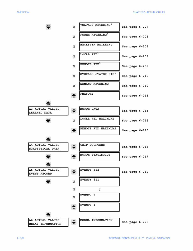
6–200 369 MOTOR MANAGEMENT RELAY– INSTRUCTION MANUAL
OVERVIEW CHAPTER 6: ACTUAL VALUES
VOLTAGE METERING1See page 6–207
POWER METERING1See page 6–208
BACKSPIN METERINGSee page 6–208
LOCAL RTD2See page 6–209
REMOTE RTD3See page 6–209
OVERALL STATOR RTD4See page 6–210
DEMAND METERINGSee page 6–210
PHASORSSee page 6–211
A3 ACTUAL VALUESLEARNED DATA
MOTOR DATASee page 6–213
LOCAL RTD MAXIMUMSSee page 6–214
REMOTE RTD MAXIMUMSSee page 6–215
A4 ACTUAL VALUESSTATISTICAL DATA
TRIP COUNTERSSee page 6–216
MOTOR STATISTICSSee page 6–217
A5 ACTUAL VALUESEVENT RECORD
EVENT: 512See page 6–219
EVENT: 511
EVENT: 2
EVENT: 1
A6 ACTUAL VALUESRELAY INFORMATION
MODEL INFORMATIONSee page 6–220

CHAPTER 6: ACTUAL VALUES OVERVIEW
369 MOTOR MANAGEMENT RELAY– INSTRUCTION MANUAL 6–201
FIRMWARE VERSIONSee page 6–220
1.Only shown if option M or B is installed2.Only shown if option R is installed3.Only shown if Channel 3 Application is programmmed as RRTD4.Only shown if option R is installed or Channel 3 Application is programmmed as RRTD
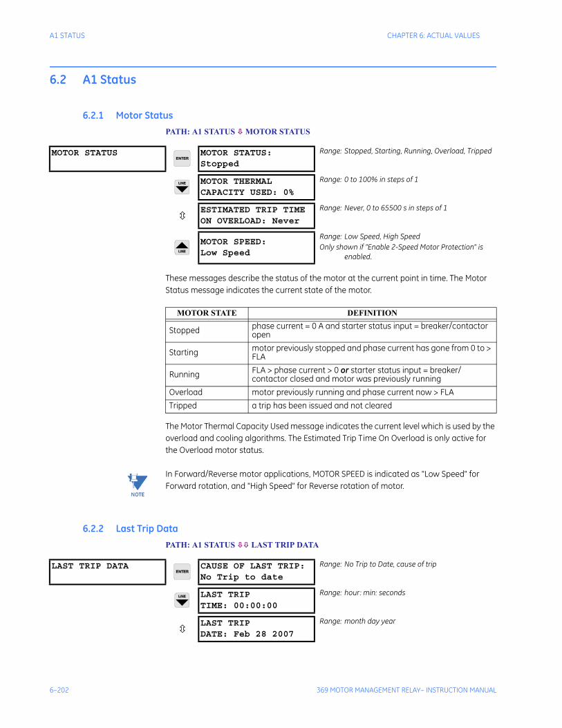
6–202 369 MOTOR MANAGEMENT RELAY– INSTRUCTION MANUAL
A1 STATUS CHAPTER 6: ACTUAL VALUES
6.2 A1 Status
6.2.1 Motor StatusPATH: A1 STATUS MOTOR STATUS
These messages describe the status of the motor at the current point in time. The Motor Status message indicates the current state of the motor.
The Motor Thermal Capacity Used message indicates the current level which is used by the overload and cooling algorithms. The Estimated Trip Time On Overload is only active for the Overload motor status.
Note In Forward/Reverse motor applications, MOTOR SPEED is indicated as "Low Speed" for Forward rotation, and "High Speed" for Reverse rotation of motor.
6.2.2 Last Trip DataPATH: A1 STATUS LAST TRIP DATA
MOTOR STATUS MOTOR STATUS:Stopped
Range: Stopped, Starting, Running, Overload, Tripped
MOTOR THERMALCAPACITY USED: 0%
Range: 0 to 100% in steps of 1
ESTIMATED TRIP TIMEON OVERLOAD: Never
Range: Never, 0 to 65500 s in steps of 1
MOTOR SPEED: Low Speed
Range: Low Speed, High SpeedOnly shown if "Enable 2-Speed Motor Protection" is
enabled.
MOTOR STATE DEFINITION
Stopped phase current = 0 A and starter status input = breaker/contactor open
Starting motor previously stopped and phase current has gone from 0 to > FLA
Running FLA > phase current > 0 or starter status input = breaker/contactor closed and motor was previously running
Overload motor previously running and phase current now > FLATripped a trip has been issued and not cleared
LAST TRIP DATA CAUSE OF LAST TRIP:No Trip to date
Range: No Trip to Date, cause of trip
LAST TRIPTIME: 00:00:00
Range: hour: min: seconds
LAST TRIPDATE: Feb 28 2007
Range: month day year
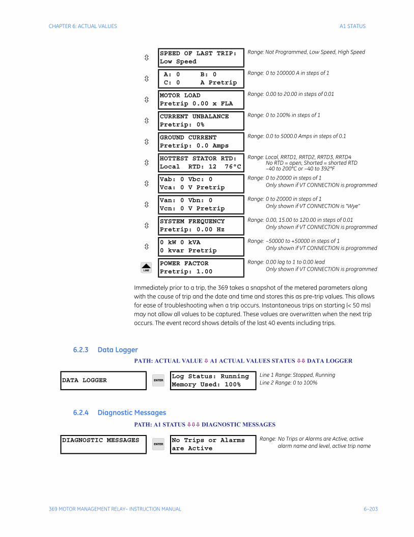
CHAPTER 6: ACTUAL VALUES A1 STATUS
369 MOTOR MANAGEMENT RELAY– INSTRUCTION MANUAL 6–203
Immediately prior to a trip, the 369 takes a snapshot of the metered parameters along with the cause of trip and the date and time and stores this as pre-trip values. This allows for ease of troubleshooting when a trip occurs. Instantaneous trips on starting (< 50 ms) may not allow all values to be captured. These values are overwritten when the next trip occurs. The event record shows details of the last 40 events including trips.
6.2.3 Data LoggerPATH: ACTUAL VALUE A1 ACTUAL VALUES STATUS DATA LOGGER
6.2.4 Diagnostic MessagesPATH: A1 STATUS DIAGNOSTIC MESSAGES
SPEED OF LAST TRIP:Low Speed
Range: Not Programmed, Low Speed, High Speed
A: 0 B: 0C: 0 A Pretrip
Range: 0 to 100000 A in steps of 1
MOTOR LOADPretrip 0.00 x FLA
Range: 0.00 to 20.00 in steps of 0.01
CURRENT UNBALANCEPretrip: 0%
Range: 0 to 100% in steps of 1
GROUND CURRENTPretrip: 0.0 Amps
Range: 0.0 to 5000.0 Amps in steps of 0.1
HOTTEST STATOR RTD:Local RTD: 12 76°C
Range: Local, RRTD1, RRTD2, RRTD3, RRTD4No RTD = open, Shorted = shorted RTD–40 to 200°C or –40 to 392°F
Vab: 0 Vbc: 0Vca: 0 V Pretrip
Range: 0 to 20000 in steps of 1Only shown if VT CONNECTION is programmed
Van: 0 Vbn: 0Vcn: 0 V Pretrip
Range: 0 to 20000 in steps of 1Only shown if VT CONNECTION is "Wye"
SYSTEM FREQUENCYPretrip: 0.00 Hz
Range: 0.00, 15.00 to 120.00 in steps of 0.01Only shown if VT CONNECTION is programmed
0 kW 0 kVA0 kvar Pretrip
Range: –50000 to +50000 in steps of 1Only shown if VT CONNECTION is programmed
POWER FACTORPretrip: 1.00
Range: 0.00 lag to 1 to 0.00 leadOnly shown if VT CONNECTION is programmed
DATA LOGGERLog Status: RunningMemory Used: 100%
Line 1 Range: Stopped, RunningLine 2 Range: 0 to 100%
DIAGNOSTIC MESSAGES No Trips or Alarmsare Active
Range: No Trips or Alarms are Active, active alarm name and level, active trip name
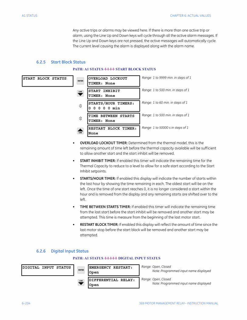
6–204 369 MOTOR MANAGEMENT RELAY– INSTRUCTION MANUAL
A1 STATUS CHAPTER 6: ACTUAL VALUES
Any active trips or alarms may be viewed here. If there is more than one active trip or alarm, using the Line Up and Down keys will cycle through all the active alarm messages. If the Line Up and Down keys are not pressed, the active messages will automatically cycle. The current level causing the alarm is displayed along with the alarm name.
6.2.5 Start Block StatusPATH: A1 STATUS START BLOCK STATUS
• OVERLOAD LOCKOUT TIMER: Determined from the thermal model, this is the remaining amount of time left before the thermal capacity available will be sufficient to allow another start and the start inhibit will be removed.
• START INHIBIT TIMER: If enabled this timer will indicate the remaining time for the Thermal Capacity to reduce to a level to allow for a safe start according to the Start Inhibit setpoints.
• STARTS/HOUR TIMER: If enabled this display will indicate the number of starts within the last hour by showing the time remaining in each. The oldest start will be on the left. Once the time of one start reaches 0, it is no longer considered a start within the hour and is removed from the display and any remaining starts are shifted over to the left.
• TIME BETWEEN STARTS TIMER: If enabled this timer will indicate the remaining time from the last start before the start inhibit will be removed and another start may be attempted. This time is measure from the beginning of the last motor start.
• RESTART BLOCK TIMER: If enabled this display will reflect the amount of time since the last motor stop before the start block will be removed and another start may be attempted.
6.2.6 Digital Input StatusPATH: A1 STATUS DIGITAL INPUT STATUS
START BLOCK STATUS OVERLOAD LOCKOUTTIMER: None
Range: 1 to 9999 min. in steps of 1
START INHIBITTIMER: None
Range: 1 to 500 min. in steps of 1
STARTS/HOUR TIMERS:0 0 0 0 0 min
Range: 1 to 60 min. in steps of 1
TIME BETWEEN STARTSTIMER: None
Range: 1 to 500 min. in steps of 1
RESTART BLOCK TIMER:None
Range: 1 to 50000 s in steps of 1
DIGITAL INPUT STATUS EMERGENCY RESTART:Open
Range: Open, ClosedNote: Programmed input name displayed
DIFFERENTIAL RELAY:Open
Range: Open, ClosedNote: Programmed input name displayed

CHAPTER 6: ACTUAL VALUES A1 STATUS
369 MOTOR MANAGEMENT RELAY– INSTRUCTION MANUAL 6–205
The present state of the digital inputs will be displayed here.
SPEED SWITCH:Open
Range: Open, ClosedNote: Programmed input name displayed
RESET:Open
Range: Open, ClosedNote: Programmed input name displayed
ACCESS:Open
Range: Open, ClosedNote: Programmed input name displayed
SPARE:Open
Range: Open, ClosedNote: Programmed input name displayed
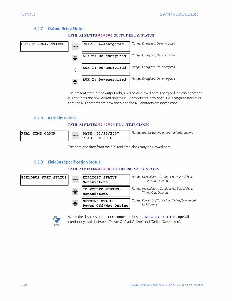
6–206 369 MOTOR MANAGEMENT RELAY– INSTRUCTION MANUAL
A1 STATUS CHAPTER 6: ACTUAL VALUES
6.2.7 Output Relay StatusPATH: A1 STATUS OUTPUT RELAY STATUS
The present state of the output relays will be displayed here. Energized indicates that the NO contacts are now closed and the NC contacts are now open. De-energized indicates that the NO contacts are now open and the NC contacts are now closed.
6.2.8 Real Time ClockPATH: A1 STATUS REAL TIME CLOCK
The date and time from the 369 real time clock may be viewed here.
6.2.9 FieldBus Specification StatusPATH: A1 STATUS FIELDBUS SPEC STATUS
Note When the device is on the non-connected bus, the NETWORK STATUS message will continually cycle between “Power Off/Not Online” and “Online/Connected”.
OUTPUT RELAY STATUS TRIP: De–energized Range: Energized, De–energized
ALARM: De–energized Range: Energized, De–energized
AUX 1: De–energized Range: Energized, De–energized
AUX 2: De–energized Range: Energized, De–energized
REAL TIME CLOCK DATE: 02/28/2007TIME: 00:00:00
Range: month/day/year, hour: minute: second
FIELDBUS SPEC STATUS EXPLICIT STATUS:Nonexistent
Range: Nonexistent, Configuring, Established,Timed Out, Deleted
IO POLLED STATUS:Nonexistent
Range: Nonexistent, Configuring, Established,Timed Out, Deleted
NETWORK STATUS:Power Off/Not Online
Range: Power Off/Not Online, Online/Connected,Link Failure
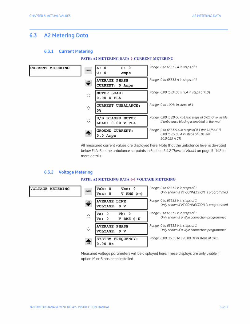
CHAPTER 6: ACTUAL VALUES A2 METERING DATA
369 MOTOR MANAGEMENT RELAY– INSTRUCTION MANUAL 6–207
6.3 A2 Metering Data
6.3.1 Current MeteringPATH: A2 METERING DATA CURRENT METERING
All measured current values are displayed here. Note that the unbalance level is de-rated below FLA. See the unbalance setpoints in Section 5.4.2 Thermal Model on page 5–142 for more details.
6.3.2 Voltage MeteringPATH: A2 METERING DATA VOLTAGE METERING
Measured voltage parameters will be displayed here. These displays are only visible if option M or B has been installed.
CURRENT METERING A: 0 B: 0C: 0 Amps
Range: 0 to 65535 A in steps of 1
AVERAGE PHASECURRENT: 0 Amps
Range: 0 to 65535 A in steps of 1
MOTOR LOAD:0.00 X FLA
Range: 0.00 to 20.00 x FLA in steps of 0.01
CURRENT UNBALANCE:0%
Range: 0 to 100% in steps of 1
U/B BIASED MOTORLOAD: 0.00 x FLA
Range: 0.00 to 20.00 x FLA in steps of 0.01. Only visible if unbalance biasing is enabled in thermal
GROUND CURRENT:0.0 Amps
Range: 0 to 6553.5 A in steps of 0.1 (for 1A/5A CT)0.00 to 25.00 A in steps of 0.01 (for50:0.025 A CT)
VOLTAGE METERING Vab: 0 Vbc: 0Vca: 0 V RMS φ-φ
Range: 0 to 65535 V in steps of 1Only shown if VT CONNECTION is programmed
AVERAGE LINEVOLTAGE: 0 V
Range: 0 to 65535 V in steps of 1Only shown if VT CONNECTION is programmed
Va: 0 Vb: 0Vc: 0 V RMS φ-N
Range: 0 to 65535 V in steps of 1Only shown if a Wye connection programmed
AVERAGE PHASEVOLTAGE: 0 V
Range: 0 to 65535 V in steps of 1Only shown if a Wye connection programmed
SYSTEM FREQUENCY:0.00 Hz
Range: 0.00, 15.00 to 120.00 Hz in steps of 0.01
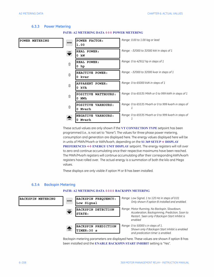
6–208 369 MOTOR MANAGEMENT RELAY– INSTRUCTION MANUAL
A2 METERING DATA CHAPTER 6: ACTUAL VALUES
6.3.3 Power MeteringPATH: A2 METERING DATA POWER METERING
These actual values are only shown if the VT CONNECTION TYPE setpoint has been programmed (i.e., is not set to “None”). The values for three phase power metering, consumption and generation are displayed here. The energy values displayed here will be in units of MWh/Mvarh or kWh/kvarh, depending on the S1 369 SETUP DISPLAY PREFERENCES ENERGY UNIT DISPLAY setpoint. The energy registers will roll over to zero and continue accumulating once their respective maximums have been reached. The MWh/Mvarh registers will continue accumulating after their corresponding kWh/kvarh registers have rolled over. The actual energy is a summation of both the kilo and Mega values.
These displays are only visible if option M or B has been installed.
6.3.4 Backspin MeteringPATH: A2 METERING DATA BACKSPIN METERING
Backspin metering parameters are displayed here. These values are shown if option B has been installed and the ENABLE BACKSPIN START INHIBIT setting is “Yes”.
POWER METERING POWER FACTOR:1.00
Range: 0.00 to 1.00 lag or lead
REAL POWER:0 kW
Range: –32000 to 32000 kW in steps of 1
REAL POWER:0 hp
Range: 0 to 42912 hp in steps of 1
REACTIVE POWER:0 kvar
Range: –32000 to 32000 kvar in steps of 1
APPARENT POWER:0 kVA
Range: 0 to 65000 kVA in steps of 1
POSITIVE WATTHOURS:0 MWh
Range: 0 to 65535 MWh or 0 to 999 kWh in steps of 1
POSITIVE VARHOURS:0 Mvarh
Range: 0 to 65535 Mvarh or 0 to 999 kvarh in steps of 1
NEGATIVE VARHOURS:0 Mvarh
Range: 0 to 65535 Mvarh or 0 to 999 kvarh in steps of 1
BACKSPIN METERING BACKSPIN FREQUENCY:Low Signal
Range: Low Signal, 1 to 120 Hz in steps of 0.01Only shown if option B installed and enabled.
BACKSPIN DETECTIONSTATE:
Range: Motor Running, No Backspin, Slowdown, Acceleration, Backspinning, Prediction, Soon to Restart. Seen only if Backspin Start Inhibit is enabled
BACKSPIN PREDICTIONTIMER:30 s
Range: 0 to 50000 s in steps of 1.Shown only if Backspin Start Inhibit is enabled and predication timer is enabled.
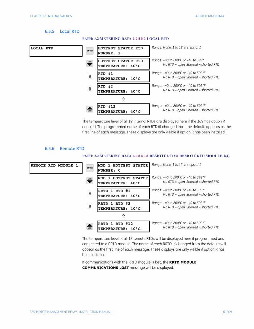
CHAPTER 6: ACTUAL VALUES A2 METERING DATA
369 MOTOR MANAGEMENT RELAY– INSTRUCTION MANUAL 6–209
6.3.5 Local RTDPATH: A2 METERING DATA LOCAL RTD
The temperature level of all 12 internal RTDs are displayed here if the 369 has option R enabled. The programmed name of each RTD (if changed from the default) appears as the first line of each message. These displays are only visible if option R has been installed.
6.3.6 Remote RTDPATH: A2 METERING DATA REMOTE RTD REMOTE RTD MODULE 1(4)
The temperature level of all 12 remote RTDs will be displayed here if programmed and connected to a RRTD module. The name of each RRTD (if changed from the default) will appear as the first line of each message. These displays are only visible if option R has been installed.
If communications with the RRTD module is lost, the RRTD MODULE
COMMUNICATIONS LOST message will be displayed.
LOCAL RTD HOTTEST STATOR RTDNUMBER: 1
Range: None, 1 to 12 in steps of 1
HOTTEST STATOR RTDTEMPERATURE: 40°C
Range: –40 to 200°C or –40 to 392°FNo RTD = open, Shorted = shorted RTD
RTD #1TEMPERATURE: 40°C
Range: –40 to 200°C or –40 to 392°FNo RTD = open, Shorted = shorted RTD
RTD #2TEMPERATURE: 40°C
Range: –40 to 200°C or –40 to 392°FNo RTD = open, Shorted = shorted RTD
RTD #12TEMPERATURE: 40°C
Range: –40 to 200°C or –40 to 392°FNo RTD = open, Shorted = shorted RTD
REMOTE RTD MODULE 1 MOD 1 HOTTEST STATORNUMBER: 0
Range: None, 1 to 12 in steps of 1
MOD 1 HOTTEST STATORTEMPERATURE: 40°C
Range: –40 to 200°C or –40 to 392°FNo RTD = open, Shorted = shorted RTD
RRTD 1 RTD #1TEMPERATURE: 40°C
Range: –40 to 200°C or –40 to 392°FNo RTD = open, Shorted = shorted RTD
RRTD 1 RTD #2TEMPERATURE: 40°C
Range: –40 to 200°C or –40 to 392°FNo RTD = open, Shorted = shorted RTD
RRTD 1 RTD #12TEMPERATURE: 40°C
Range: –40 to 200°C or –40 to 392°FNo RTD = open, Shorted = shorted RTD
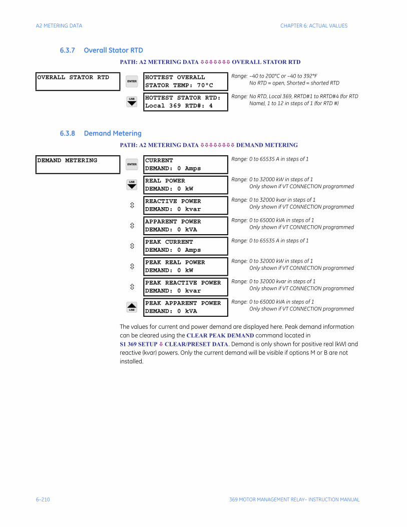
6–210 369 MOTOR MANAGEMENT RELAY– INSTRUCTION MANUAL
A2 METERING DATA CHAPTER 6: ACTUAL VALUES
6.3.7 Overall Stator RTDPATH: A2 METERING DATA OVERALL STATOR RTD
6.3.8 Demand MeteringPATH: A2 METERING DATA DEMAND METERING
The values for current and power demand are displayed here. Peak demand information can be cleared using the CLEAR PEAK DEMAND command located in S1 369 SETUP CLEAR/PRESET DATA. Demand is only shown for positive real (kW) and reactive (kvar) powers. Only the current demand will be visible if options M or B are not installed.
OVERALL STATOR RTD HOTTEST OVERALLSTATOR TEMP: 70°C
Range: –40 to 200°C or –40 to 392°FNo RTD = open, Shorted = shorted RTD
HOTTEST STATOR RTD:Local 369 RTD#: 4
Range: No RTD, Local 369, RRTD#1 to RRTD#4 (for RTD Name), 1 to 12 in steps of 1 (for RTD #)
DEMAND METERING CURRENTDEMAND: 0 Amps
Range: 0 to 65535 A in steps of 1
REAL POWERDEMAND: 0 kW
Range: 0 to 32000 kW in steps of 1Only shown if VT CONNECTION programmed
REACTIVE POWERDEMAND: 0 kvar
Range: 0 to 32000 kvar in steps of 1Only shown if VT CONNECTION programmed
APPARENT POWERDEMAND: 0 kVA
Range: 0 to 65000 kVA in steps of 1Only shown if VT CONNECTION programmed
PEAK CURRENTDEMAND: 0 Amps
Range: 0 to 65535 A in steps of 1
PEAK REAL POWERDEMAND: 0 kW
Range: 0 to 32000 kW in steps of 1Only shown if VT CONNECTION programmed
PEAK REACTIVE POWERDEMAND: 0 kvar
Range: 0 to 32000 kvar in steps of 1Only shown if VT CONNECTION programmed
PEAK APPARENT POWERDEMAND: 0 kVA
Range: 0 to 65000 kVA in steps of 1Only shown if VT CONNECTION programmed
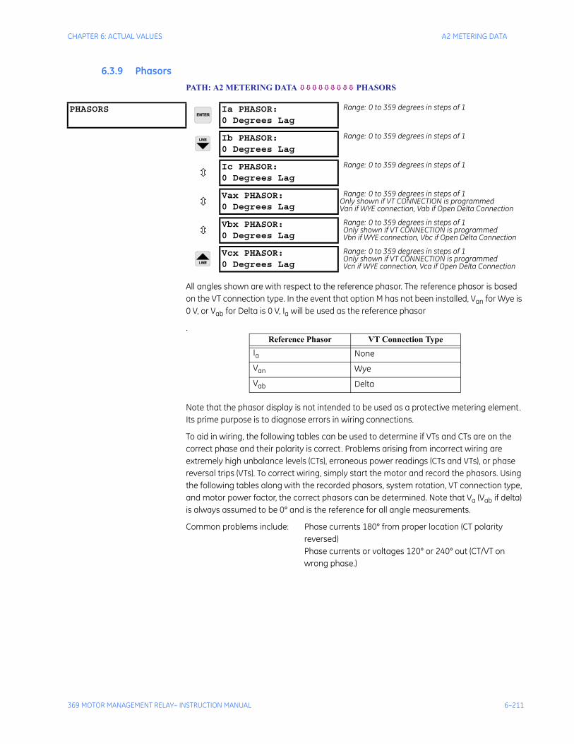
CHAPTER 6: ACTUAL VALUES A2 METERING DATA
369 MOTOR MANAGEMENT RELAY– INSTRUCTION MANUAL 6–211
6.3.9 PhasorsPATH: A2 METERING DATA PHASORS
All angles shown are with respect to the reference phasor. The reference phasor is based on the VT connection type. In the event that option M has not been installed, Van for Wye is 0 V, or Vab for Delta is 0 V, Ia will be used as the reference phasor
.
Note that the phasor display is not intended to be used as a protective metering element. Its prime purpose is to diagnose errors in wiring connections.
To aid in wiring, the following tables can be used to determine if VTs and CTs are on the correct phase and their polarity is correct. Problems arising from incorrect wiring are extremely high unbalance levels (CTs), erroneous power readings (CTs and VTs), or phase reversal trips (VTs). To correct wiring, simply start the motor and record the phasors. Using the following tables along with the recorded phasors, system rotation, VT connection type, and motor power factor, the correct phasors can be determined. Note that Va (Vab if delta) is always assumed to be 0° and is the reference for all angle measurements.
Common problems include: Phase currents 180° from proper location (CT polarity reversed)Phase currents or voltages 120° or 240° out (CT/VT on wrong phase.)
PHASORS Ia PHASOR:0 Degrees Lag
Range: 0 to 359 degrees in steps of 1
Ib PHASOR:0 Degrees Lag
Range: 0 to 359 degrees in steps of 1
Ic PHASOR:0 Degrees Lag
Range: 0 to 359 degrees in steps of 1
Vax PHASOR:0 Degrees Lag
Range: 0 to 359 degrees in steps of 1Only shown if VT CONNECTION is programmedVan if WYE connection, Vab if Open Delta Connection
Vbx PHASOR:0 Degrees Lag
Range: 0 to 359 degrees in steps of 1Only shown if VT CONNECTION is programmedVbn if WYE connection, Vbc if Open Delta Connection
Vcx PHASOR:0 Degrees Lag
Range: 0 to 359 degrees in steps of 1Only shown if VT CONNECTION is programmedVcn if WYE connection, Vca if Open Delta Connection
Reference Phasor VT Connection TypeIa None
Van Wye
Vab Delta
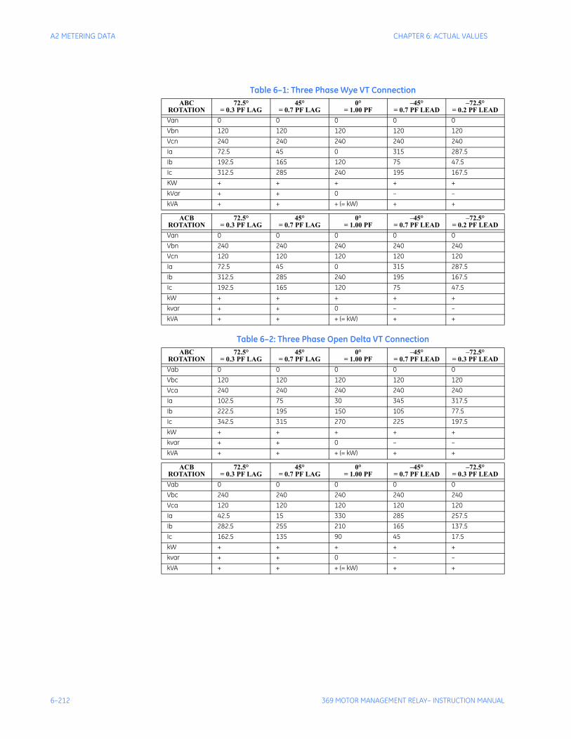
6–212 369 MOTOR MANAGEMENT RELAY– INSTRUCTION MANUAL
A2 METERING DATA CHAPTER 6: ACTUAL VALUES
Table 6–1: Three Phase Wye VT ConnectionABC
ROTATION72.5°
= 0.3 PF LAG45°
= 0.7 PF LAG0°
= 1.00 PF–45°
= 0.7 PF LEAD–72.5°
= 0.2 PF LEADVan 0 0 0 0 0Vbn 120 120 120 120 120Vcn 240 240 240 240 240Ia 72.5 45 0 315 287.5Ib 192.5 165 120 75 47.5Ic 312.5 285 240 195 167.5KW + + + + +kVar + + 0 – –kVA + + + (= kW) + +
ACBROTATION
72.5°= 0.3 PF LAG
45°= 0.7 PF LAG
0°= 1.00 PF
–45°= 0.7 PF LEAD
–72.5°= 0.2 PF LEAD
Van 0 0 0 0 0Vbn 240 240 240 240 240Vcn 120 120 120 120 120Ia 72.5 45 0 315 287.5Ib 312.5 285 240 195 167.5Ic 192.5 165 120 75 47.5kW + + + + +kvar + + 0 – –kVA + + + (= kW) + +
Table 6–2: Three Phase Open Delta VT ConnectionABC
ROTATION72.5°
= 0.3 PF LAG45°
= 0.7 PF LAG0°
= 1.00 PF–45°
= 0.7 PF LEAD–72.5°
= 0.3 PF LEADVab 0 0 0 0 0Vbc 120 120 120 120 120Vca 240 240 240 240 240Ia 102.5 75 30 345 317.5Ib 222.5 195 150 105 77.5Ic 342.5 315 270 225 197.5kW + + + + +kvar + + 0 – –kVA + + + (= kW) + +
ACBROTATION
72.5°= 0.3 PF LAG
45°= 0.7 PF LAG
0°= 1.00 PF
–45°= 0.7 PF LEAD
–72.5°= 0.3 PF LEAD
Vab 0 0 0 0 0Vbc 240 240 240 240 240Vca 120 120 120 120 120Ia 42.5 15 330 285 257.5Ib 282.5 255 210 165 137.5Ic 162.5 135 90 45 17.5kW + + + + +kvar + + 0 – –kVA + + + (= kW) + +
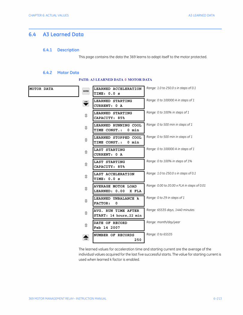
CHAPTER 6: ACTUAL VALUES A3 LEARNED DATA
369 MOTOR MANAGEMENT RELAY– INSTRUCTION MANUAL 6–213
6.4 A3 Learned Data
6.4.1 DescriptionThis page contains the data the 369 learns to adapt itself to the motor protected.
6.4.2 Motor DataPATH: A3 LEARNED DATA MOTOR DATA
The learned values for acceleration time and starting current are the average of the individual values acquired for the last five successful starts. The value for starting current is used when learned k factor is enabled.
MOTOR DATA LEARNED ACCELERATIONTIME: 0.0 s
Range: 1.0 to 250.0 s in steps of 0.1
LEARNED STARTINGCURRENT: 0 A
Range: 0 to 100000 A in steps of 1
LEARNED STARTINGCAPACITY: 85%
Range: 0 to 100% in steps of 1
LEARNED RUNNING COOLTIME CONST.: 0 min
Range: 0 to 500 min in steps of 1
LEARNED STOPPED COOLTIME CONST.: 0 min
Range: 0 to 500 min in steps of 1
LAST STARTINGCURRENT: 0 A
Range: 0 to 100000 A in steps of 1
LAST STARTINGCAPACITY: 85%
Range: 0 to 100% in steps of 1%
LAST ACCELERATIONTIME: 0.0 s
Range: 1.0 to 250.0 s in steps of 0.1
AVERAGE MOTOR LOADLEARNED: 0.00 X FLA
Range: 0.00 to 20.00 x FLA in steps of 0.01
LEARNED UNBALANCE kFACTOR: 0
Range: 0 to 29 in steps of 1
AVG. RUN TIME AFTERSTART: 14 hours,22 min
Range: 65535 days, 1440 minutes
DATE OF RECORDFeb 14 2007
Range: month/day/year
NUMBER OF RECORDS 250
Range: 0 to 65535
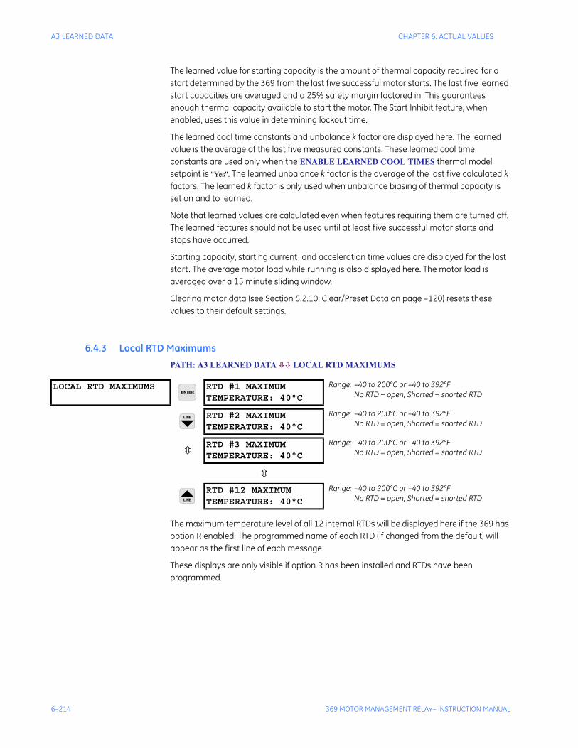
6–214 369 MOTOR MANAGEMENT RELAY– INSTRUCTION MANUAL
A3 LEARNED DATA CHAPTER 6: ACTUAL VALUES
The learned value for starting capacity is the amount of thermal capacity required for a start determined by the 369 from the last five successful motor starts. The last five learned start capacities are averaged and a 25% safety margin factored in. This guarantees enough thermal capacity available to start the motor. The Start Inhibit feature, when enabled, uses this value in determining lockout time.
The learned cool time constants and unbalance k factor are displayed here. The learned value is the average of the last five measured constants. These learned cool time constants are used only when the ENABLE LEARNED COOL TIMES thermal model setpoint is "Yes". The learned unbalance k factor is the average of the last five calculated k factors. The learned k factor is only used when unbalance biasing of thermal capacity is set on and to learned.
Note that learned values are calculated even when features requiring them are turned off. The learned features should not be used until at least five successful motor starts and stops have occurred.
Starting capacity, starting current, and acceleration time values are displayed for the last start. The average motor load while running is also displayed here. The motor load is averaged over a 15 minute sliding window.
Clearing motor data (see Section 5.2.10: Clear/Preset Data on page –120) resets these values to their default settings.
6.4.3 Local RTD MaximumsPATH: A3 LEARNED DATA LOCAL RTD MAXIMUMS
The maximum temperature level of all 12 internal RTDs will be displayed here if the 369 has option R enabled. The programmed name of each RTD (if changed from the default) will appear as the first line of each message.
These displays are only visible if option R has been installed and RTDs have been programmed.
LOCAL RTD MAXIMUMS RTD #1 MAXIMUMTEMPERATURE: 40°C
Range: –40 to 200°C or –40 to 392°FNo RTD = open, Shorted = shorted RTD
RTD #2 MAXIMUMTEMPERATURE: 40°C
Range: –40 to 200°C or –40 to 392°FNo RTD = open, Shorted = shorted RTD
RTD #3 MAXIMUMTEMPERATURE: 40°C
Range: –40 to 200°C or –40 to 392°FNo RTD = open, Shorted = shorted RTD
RTD #12 MAXIMUMTEMPERATURE: 40°C
Range: –40 to 200°C or –40 to 392°FNo RTD = open, Shorted = shorted RTD
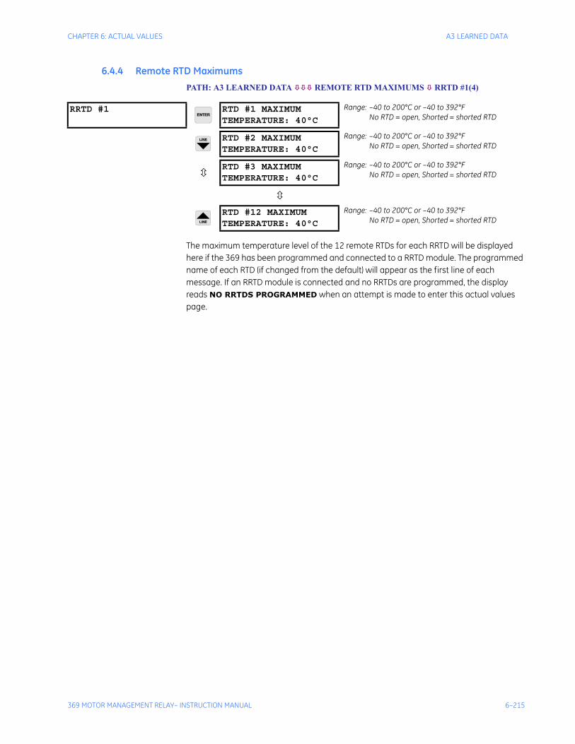
CHAPTER 6: ACTUAL VALUES A3 LEARNED DATA
369 MOTOR MANAGEMENT RELAY– INSTRUCTION MANUAL 6–215
6.4.4 Remote RTD MaximumsPATH: A3 LEARNED DATA REMOTE RTD MAXIMUMS RRTD #1(4)
The maximum temperature level of the 12 remote RTDs for each RRTD will be displayed here if the 369 has been programmed and connected to a RRTD module. The programmed name of each RTD (if changed from the default) will appear as the first line of each message. If an RRTD module is connected and no RRTDs are programmed, the display reads NO RRTDS PROGRAMMED when an attempt is made to enter this actual values page.
RRTD #1 RTD #1 MAXIMUMTEMPERATURE: 40°C
Range: –40 to 200°C or –40 to 392°FNo RTD = open, Shorted = shorted RTD
RTD #2 MAXIMUMTEMPERATURE: 40°C
Range: –40 to 200°C or –40 to 392°FNo RTD = open, Shorted = shorted RTD
RTD #3 MAXIMUMTEMPERATURE: 40°C
Range: –40 to 200°C or –40 to 392°FNo RTD = open, Shorted = shorted RTD
RTD #12 MAXIMUMTEMPERATURE: 40°C
Range: –40 to 200°C or –40 to 392°FNo RTD = open, Shorted = shorted RTD
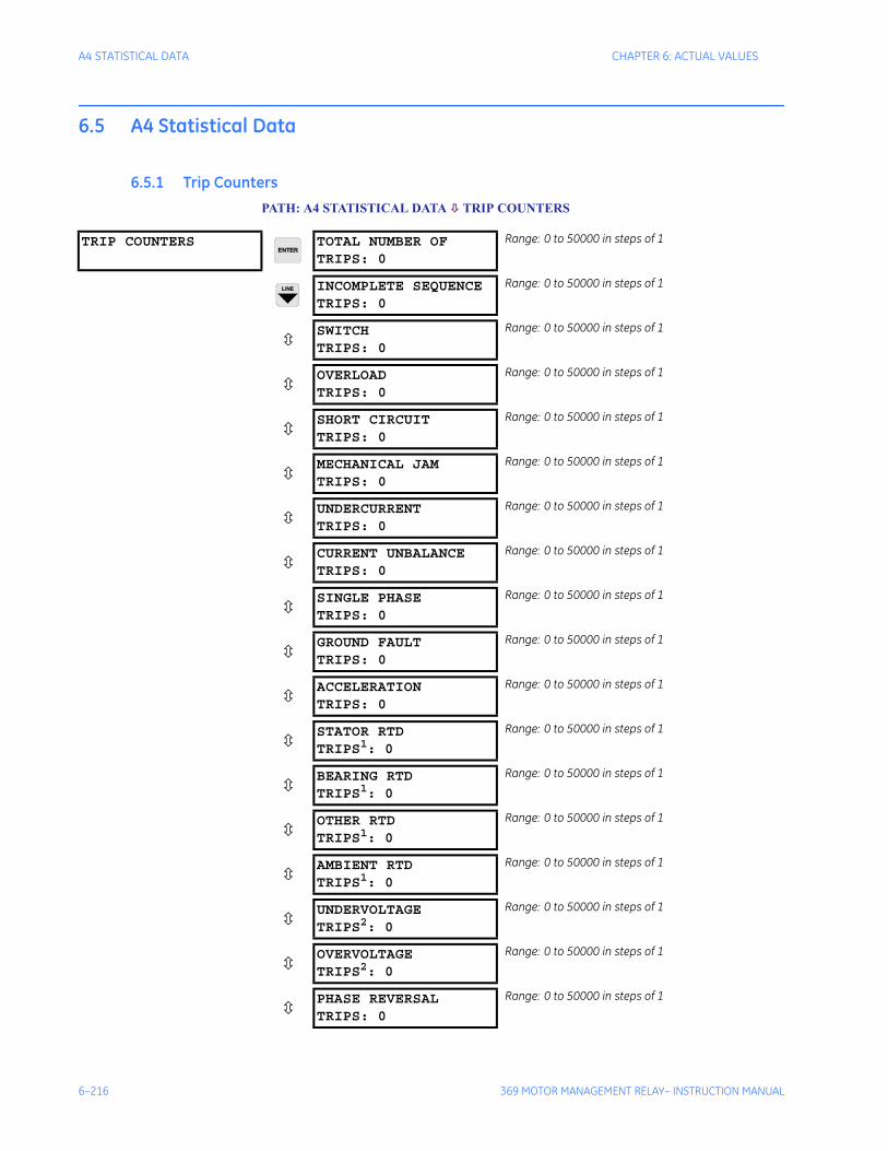
6–216 369 MOTOR MANAGEMENT RELAY– INSTRUCTION MANUAL
A4 STATISTICAL DATA CHAPTER 6: ACTUAL VALUES
6.5 A4 Statistical Data
6.5.1 Trip CountersPATH: A4 STATISTICAL DATA TRIP COUNTERS
TRIP COUNTERS TOTAL NUMBER OFTRIPS: 0
Range: 0 to 50000 in steps of 1
INCOMPLETE SEQUENCETRIPS: 0
Range: 0 to 50000 in steps of 1
SWITCHTRIPS: 0
Range: 0 to 50000 in steps of 1
OVERLOADTRIPS: 0
Range: 0 to 50000 in steps of 1
SHORT CIRCUITTRIPS: 0
Range: 0 to 50000 in steps of 1
MECHANICAL JAMTRIPS: 0
Range: 0 to 50000 in steps of 1
UNDERCURRENTTRIPS: 0
Range: 0 to 50000 in steps of 1
CURRENT UNBALANCETRIPS: 0
Range: 0 to 50000 in steps of 1
SINGLE PHASETRIPS: 0
Range: 0 to 50000 in steps of 1
GROUND FAULTTRIPS: 0
Range: 0 to 50000 in steps of 1
ACCELERATIONTRIPS: 0
Range: 0 to 50000 in steps of 1
STATOR RTDTRIPS1: 0
Range: 0 to 50000 in steps of 1
BEARING RTDTRIPS1: 0
Range: 0 to 50000 in steps of 1
OTHER RTDTRIPS1: 0
Range: 0 to 50000 in steps of 1
AMBIENT RTDTRIPS1: 0
Range: 0 to 50000 in steps of 1
UNDERVOLTAGETRIPS2: 0
Range: 0 to 50000 in steps of 1
OVERVOLTAGETRIPS2: 0
Range: 0 to 50000 in steps of 1
PHASE REVERSALTRIPS: 0
Range: 0 to 50000 in steps of 1
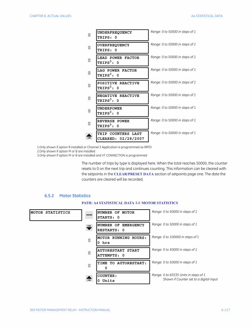
CHAPTER 6: ACTUAL VALUES A4 STATISTICAL DATA
369 MOTOR MANAGEMENT RELAY– INSTRUCTION MANUAL 6–217
The number of trips by type is displayed here. When the total reaches 50000, the counter resets to 0 on the next trip and continues counting. This information can be cleared with the setpoints in the CLEAR/PRESET DATA section of setpoints page one. The date the counters are cleared will be recorded.
6.5.2 Motor StatisticsPATH: A4 STATISTICAL DATA MOTOR STATISTICS
UNDERFREQUENCYTRIPS: 0
Range: 0 to 50000 in steps of 1
OVERFREQUENCYTRIPS: 0
Range: 0 to 50000 in steps of 1
LEAD POWER FACTORTRIPS3: 0
Range: 0 to 50000 in steps of 1
LAG POWER FACTORTRIPS3: 0
Range: 0 to 50000 in steps of 1
POSITIVE REACTIVETRIPS3: 0
Range: 0 to 50000 in steps of 1
NEGATIVE REACTIVETRIPS3: 0
Range: 0 to 50000 in steps of 1
UNDERPOWERTRIPS3: 0
Range: 0 to 50000 in steps of 1
REVERSE POWERTRIPS3: 0
Range: 0 to 50000 in steps of 1
TRIP COUNTERS LASTCLEARED: 02/28/2007
Range: 0 to 50000 in steps of 1
1.Only shown if option R installed or Channel 3 Application is programmed as RRTD2.Only shown if option M or B are installed3.Only shown if option M or B are installed and VT CONNECTION is programmed
MOTOR STATISTICS NUMBER OF MOTORSTARTS: 0
Range: 0 to 50000 in steps of 1
NUMBER OF EMERGENCYRESTARTS: 0
Range: 0 to 50000 in steps of 1
MOTOR RUNNING HOURS:0 hrs
Range: 0 to 100000 in steps of 1
AUTORESTART STARTATTEMPTS: 0
Range: 0 to 50000 in steps of 1
TIME TO AUTORESTART:0
Range: 0 to 50000 in steps of 1
COUNTER:0 Units
Range: 0 to 65535 Units in steps of 1Shown if Counter set to a digital input

6–218 369 MOTOR MANAGEMENT RELAY– INSTRUCTION MANUAL
A4 STATISTICAL DATA CHAPTER 6: ACTUAL VALUES
NUMBER OF MOTOR STARTS, and NUMBER OF EMERGENCY RESTARTS values display the number of motor starts and emergency restarts respectively. This information is useful for troubleshooting a motor failure or in understanding the history and use of a motor for maintenance purposes. When any of these counters reaches 50000, they are automatically reset to 0.
The MOTOR RUNNING HOURS indicates the elapsed time since the 369 determined the motor to be in a running state (current applied and/or starter status indicating contactor/breaker closed). The NUMBER OF MOTOR STARTS, NUMBER OF EMERGENCY RESTARTS, and MOTOR RUNNING HOURS counters can be cleared with the S1 369 SETUP CLEAR/PRESET DATA CLEAR MOTOR DATA setpoint.
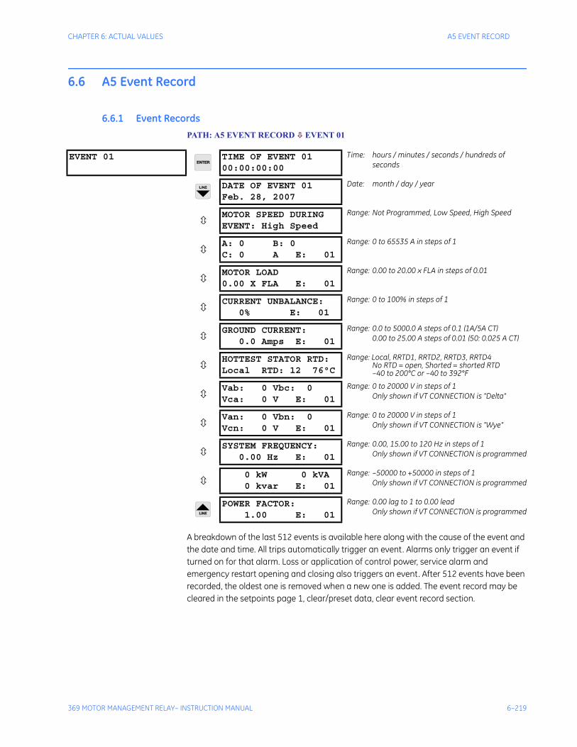
CHAPTER 6: ACTUAL VALUES A5 EVENT RECORD
369 MOTOR MANAGEMENT RELAY– INSTRUCTION MANUAL 6–219
6.6 A5 Event Record
6.6.1 Event RecordsPATH: A5 EVENT RECORD EVENT 01
A breakdown of the last 512 events is available here along with the cause of the event and the date and time. All trips automatically trigger an event. Alarms only trigger an event if turned on for that alarm. Loss or application of control power, service alarm and emergency restart opening and closing also triggers an event. After 512 events have been recorded, the oldest one is removed when a new one is added. The event record may be cleared in the setpoints page 1, clear/preset data, clear event record section.
EVENT 01 TIME OF EVENT 0100:00:00:00
Time: hours / minutes / seconds / hundreds of seconds
DATE OF EVENT 01Feb. 28, 2007
Date: month / day / year
MOTOR SPEED DURINGEVENT: High Speed
Range: Not Programmed, Low Speed, High Speed
A: 0 B: 0C: 0 A E: 01
Range: 0 to 65535 A in steps of 1
MOTOR LOAD0.00 X FLA E: 01
Range: 0.00 to 20.00 x FLA in steps of 0.01
CURRENT UNBALANCE:0% E: 01
Range: 0 to 100% in steps of 1
GROUND CURRENT:0.0 Amps E: 01
Range: 0.0 to 5000.0 A steps of 0.1 (1A/5A CT)0.00 to 25.00 A steps of 0.01 (50: 0.025 A CT)
HOTTEST STATOR RTD:Local RTD: 12 76°C
Range: Local, RRTD1, RRTD2, RRTD3, RRTD4No RTD = open, Shorted = shorted RTD–40 to 200°C or –40 to 392°F
Vab: 0 Vbc: 0Vca: 0 V E: 01
Range: 0 to 20000 V in steps of 1Only shown if VT CONNECTION is "Delta"
Van: 0 Vbn: 0Vcn: 0 V E: 01
Range: 0 to 20000 V in steps of 1Only shown if VT CONNECTION is "Wye"
SYSTEM FREQUENCY:0.00 Hz E: 01
Range: 0.00, 15.00 to 120 Hz in steps of 1Only shown if VT CONNECTION is programmed
0 kW 0 kVA0 kvar E: 01
Range: –50000 to +50000 in steps of 1Only shown if VT CONNECTION is programmed
POWER FACTOR:1.00 E: 01
Range: 0.00 lag to 1 to 0.00 leadOnly shown if VT CONNECTION is programmed
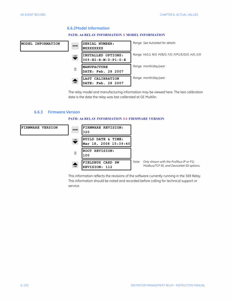
6–220 369 MOTOR MANAGEMENT RELAY– INSTRUCTION MANUAL
A5 EVENT RECORD CHAPTER 6: ACTUAL VALUES
0.1A6 RELAY INFORMATION6.6.2Model InformationPATH: A6 RELAY INFORMATION MODEL INFORMATION
The relay model and manufacturing information may be viewed here. The last calibration date is the date the relay was last calibrated at GE Multilin.
6.6.3 Firmware VersionPATH: A6 RELAY INFORMATION FIRMWARE VERSION
This information reflects the revisions of the software currently running in the 369 Relay. This information should be noted and recorded before calling for technical support or service.
MODEL INFORMATION SERIAL NUMBER:MXXXXXXXX
Range: See Autolabel for details
INSTALLED OPTIONS:369-HI-R-M-0-P1-0-E
Range: HI/LO, R/0, M/B/0, F/0, P/P1/E/D/0, H/0, E/0
MANUFACTUREDATE: Feb. 28 2007
Range: month/day/year
LAST CALIBRATIONDATE: Feb. 28 2007
Range: month/day/year
FIRMWARE VERSION FIRMWARE REVISION:320
BUILD DATE & TIME:Mar 18, 2008 15:39:40
BOOT REVISION:100
FIELDBUS CARD SWREVISION: 112
Note: Only shown with the Profibus (P or P1), Modbus/TCP (E), and DeviceNet (D) options.

369 MOTOR MANAGEMENT RELAY– INSTRUCTION MANUAL 7–221
369 Motor Management Relay
Chapter 7: Applications
Digital EnergyMultilin
Applications
7.1 269-369 Comparison
7.1.1 369 and 269plus Comparison
Table 7–1: Comparison Between 369 Relay and 269plus
369 269Plus
All options can be turned on or added in the field
Must be returned for option change or add other devices
Current and optional voltage inputs are included on all relays
Current inputs only. Must use additional meter device to obtain voltage and power measurements.
Optional 12 RTDs with an additional 12 RTDs available with the RRTD. All RTDs are individually configured(100P, 100N, 120N, 10C)
10 RTDs not programmable, must be specified at time of order.
Fully programmable digital inputs No programmable digital inputs
4 programmable analog outputs assignable to 33 parameters
1 Analog output programmable for 5 parameters
1 RS232 (19.2K baud), 3 RS485 (1200 TO 19.2K baud programmable) communication ports. Also Optional profibus port and optional fiber optics port
1 RS485 Communication port (2400 baud maximum)
Flash memory firmware upgrade thru PC software and comm port
EPROM must be replaced to change firmware
EVENT RECORDER: time and date stamp last 512 events. Records all trips and selectable alarms
Displays cause of last trip and last event
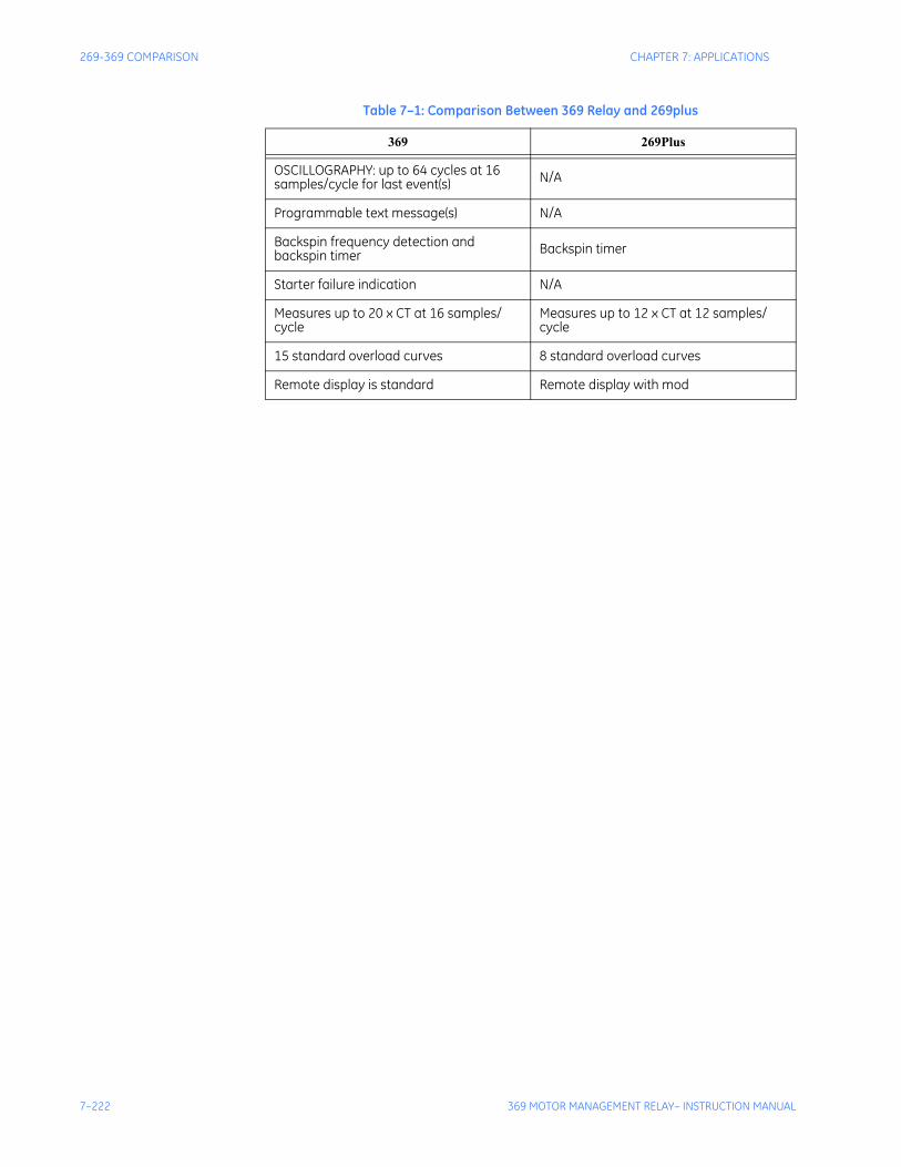
7–222 369 MOTOR MANAGEMENT RELAY– INSTRUCTION MANUAL
269-369 COMPARISON CHAPTER 7: APPLICATIONS
OSCILLOGRAPHY: up to 64 cycles at 16 samples/cycle for last event(s) N/A
Programmable text message(s) N/A
Backspin frequency detection and backspin timer Backspin timer
Starter failure indication N/A
Measures up to 20 x CT at 16 samples/cycle
Measures up to 12 x CT at 12 samples/cycle
15 standard overload curves 8 standard overload curves
Remote display is standard Remote display with mod
Table 7–1: Comparison Between 369 Relay and 269plus
369 269Plus

CHAPTER 7: APPLICATIONS 369 FAQS
369 MOTOR MANAGEMENT RELAY– INSTRUCTION MANUAL 7–223
7.2 369 FAQs
7.2.1 Frequently Asked Questions (FAQs)1. What is the difference between Firmware and Software?
Firmware is the program running inside the relay, which is responsible for all relay protection and control elements. Software is the program running on the PC, which is used to communicate with the relay and provide relay control remotely in a user friendly format.
2. How can I obtain copies of the latest manual and PC software?
I need it now!: via the GE Multilin website at http://www.GEindustrial.com/multilin
I guess I can wait: fax a request to the GE Multilin Literature department at (905) 201-2113
3. Cannot communicate through the front port (RS232).
Check the following settings:• Communication Port (COM1, COM2, COM3 etc.) on PC or PLC
• Parity settings must match between the relay and the master (PC or PLC)
• Baud rate setting on the master (PC or PLC) must match RS232 baud rate on the 369 relay.
• Cable has to be a straight through cable, do not use null modem cables where pin 2 and 3 are transposed
• Check the pin outs of RS232 cable (TX - pin 2, RX - pin 3, GND - pin 5)
4. Cannot communicate with RS485.
Check the following settings:• Communication Port (COM1, COM2, COM3 etc.) on PC or PLC
• Parity settings must match between the relay and the master (PC or PLC)
• Baud rate must match between the relay and the master
• Slave address polled must match between the relay and the master
• Is terminating filter circuit present?
• Are you communicating in half duplex? (369 communicates in half duplex mode only)
• Is wiring correct? (“+” wire should go to “+” terminal of the relay, and “–” goes to “–” terminal)
• Is the RS485 cable shield grounded? (shielding diminishes noise from external EM radiation)
Check the appropriate communication port LED on the relay. The LED should be solidly lit when communicating properly. The LED will blink on and off when the relay has communication difficulties and the LED will be off if no activity detected on communication lines.
5. Can the 4 wire RS485 (full duplex) be used with 369?
No, the 369 communicates in 2-wire half duplex mode only. However, there are commercial RS485 converters that will convert a 4 wire to a 2 wire system.
7–224 369 MOTOR MANAGEMENT RELAY– INSTRUCTION MANUAL
369 FAQS CHAPTER 7: APPLICATIONS
6. Cannot store setpoint into the relay.
Check and ensure the ACCESS switch is shorted, and check for any PASSCODE restrictions.
7. The 369 relay displays incorrect power reading, yet the power system is balanced. What could be the possible reasons?
It is highly possible that the secondary wiring to the relay is not correct. Incorrect power can be read when any of the A, B, or C phases are swapped, a CT or VT is wired backwards, or the relay is programmed as ABC sequence when the power system is actually ACB and vice versa. The easiest way to verify is to check the voltage and the current phasor readings on the 369 relay and ensure that each respective voltage and current angles match.
8. What are the merits of a residual ground fault connection versus a core balance connection?
The use of a zero sequence (core balance) CT to detect ground current is recommended over the G/F residual connection. This is especially true at motor starting. During across-the-line starting of large motors, care must be taken to prevent the high inrush current from operating the ground element of the 369. This is especially true when using the residual connection of 2 or 3 CTs.
In a residual connection, the unequal saturation of the current transformers, size and location of motor, size of power system, resistance in the power system from the source to the motor, type of iron used in the motor core & saturation density, and residual flux levels may all contribute to the production of a false residual current in the secondary or relay circuit. The common practice in medium and high voltage systems is to use low resistance grounding. By using the “doughnut CT” scheme, such systems offer the advantages of speed and reliability without much concern for starting current, fault contribution by the motor, or false residual current.
When a zero sequence CT is used, a voltage is generated in the secondary winding only when zero sequence current is flowing in the primary leads. Since virtually all motors have their neutrals ungrounded, no zero sequence current can flow in the motor leads unless there is a ground fault on the motor side.
9. Can I use an 86 lockout on the 369?
Yes, but if an external 86 lockout device is used and connected to the 369, ensure the 369 is reset prior to attempting to reset the lockout switch. If the 369 is still tripped, it will immediately re-trip the lockout switch. Also, if the lockout switch is held reset, the high current draw of the switch coil may cause damage to itself and/or the 369 output relay.
10. Can I assign more than one output relay to be blocked when using Start Inhibits?
Yes, but keep in mind that if two output relays are wired in series to inhibit a start it is possible that another element could be programmed to control one or both of the relays. If this is happening and the other element is programmed with a longer delay time, this will make it seem as if the Start Inhibit is not working properly when in fact, it is.
11. Can I name a digital input?
Yes. By configuring the digital input as "General" a menu will appear that will allow naming.
CHAPTER 7: APPLICATIONS 369 FAQS
369 MOTOR MANAGEMENT RELAY– INSTRUCTION MANUAL 7–225
12. Can I apply an external voltage to the digital inputs on the 369?
No. The 369 uses an internal voltage to operate the digital inputs. Applying an external voltage may cause damage to the internal circuitry.
13. Can I upload setpoint files from previous versions to the latest version of firmware?
Yes, with the exception of setpoint files from versions 1.10 and 1.12. Unfortunately these setpoint files must be rewritten, as they are not compatible.
14. What method does the 369 use to calculate current unbalance?
The 369 uses the NEMA method. Previous revisions of the 369 manual have incorrectly included a functional test that measured the ratio of negative sequence current to positive sequence current. The NEMA method is as follows:
If Iavg ≥ IFLA, then
where:Iavg = average phase currentImax = current in a phase with maximum derivation from IavgIFLA = motor full load amps setting
If Iavg < IFLA, then
To prevent nuisance trips/alarms on lightly loaded motors when a much larger unbalance level will not damage the rotor, the unbalance protection will automatically be defeated if the average motor current is less than 30% of the full load current (IFLA) setting.
15. I need to update the options for my 369/RRTD in the field, can I do this?
Yes. All options of the 369/RRTD can be turned on or added in the field. To do this contact the factory.
16. Can I test my output relays?
Yes, but keep in mind that the output relays cannot be forced into a different state while the motor is running.
17. Is the communication interface for Profibus RS232 or RS485?
It is RS485. The 9-pin connector on the rear of the 369 is the connector used by the manufacturer of the Profibus card and although it is a DB-9, the electrical interface is RS485.
18. Can I use the options enabler code to upgrade my 369 in the field to get the Profibus option?
Yes, but keep in mind that there is a Profibus card that is required and is not installed in units that were not ordered from the factory with the Profibus option.
19. Can the 369 be used as a remote unit, similar to the 269 remote?
Yes. Every 369 can be used as remote. When ordering the 369, an external 15 foot cable must be ordered.
20. Can the RRTD module be used as a standalone unit?
UnbalanceImax Iavg–
Iavg-------------------------- 100×=
UnbalanceImax Iavg–
IFLA-------------------------- 100×=
7–226 369 MOTOR MANAGEMENT RELAY– INSTRUCTION MANUAL
369 FAQS CHAPTER 7: APPLICATIONS
Yes. The RRTD unit with the IO option, has 4 output relays, 6 digital inputs and 4 analog outputs. With this option the RRTD can provide temperature protection.
21. Why is there a filter ground and a safety ground connection? Why are they separate?
The safety ground ensures operator safety with regards to hazardous shocks; the filter ground protects the internal electronic circuitry from transient noise.
These two grounds are separated for hi-pot (dielectric strength) testing purposes. Both grounds should be tied to the ground bus external to the relay.
22. 369 doesn't communicate with ethernet after change in IP address, what should I do?
Cycle the power supply to the 369. In order to make the new IP address active the power supply of the 369 must be recycled after changing or setting the IP address of the relay.
CHAPTER 7: APPLICATIONS 369 DO’S AND DONT’S
369 MOTOR MANAGEMENT RELAY– INSTRUCTION MANUAL 7–227
7.3 369 Do’s and Dont’s
7.3.1 Do’s and Dont’s
Do’s
Always check the power supply rating before applying power to the relay
Applying voltage greater than the maximum rating to the power supply (e.g. 120 V AC to the low-voltage rated power supply) could result in component damage to the relay's power supply. This will result in the unit no longer being able to power up.
Ensure that the 369 nominal phase current of 1 A or 5 A matches the secondary rating and the connections of the connected CTs
Unmatched CTs may result in equipment damage or inadequate protection.
Ensure that the source CT and VT polarity match the relay CT and VT polarity
Polarity of the Phase CTs is critical for power measurement, and residual ground current detection (if used). Polarity of the VTs is critical for correct power measurement and voltage phase reversal operation.
Properly ground the 369
Connect both the Filter Ground (terminal 123) and Safety Ground (terminal 126) of the 369 directly to the main GROUND BUS. The benefits of proper grounding of the 369 are numerous, e.g,
• Elimination of nuisance tripping
• Elimination of internal hardware failures
• Reliable operation of the relay
• Higher MTBF (Mean Time Between Failures)
• It is recommended that a tinned copper braided shielding and bonding cable be used. A Belden 8660 cable or equivalent should be used as a minimum to connect the relay directly to the ground bus.
Grounding of Phase and Ground CTs
All Phase and Ground CTs must be grounded. The potential difference between the CT's ground and the ground bus should be minimal (ideally zero).
It is highly recommended that the two CT leads be twisted together to minimize noise pickup, especially when the highly sensitive 50:0.025 Ground CT sensor is used.
RTDs
Consult the application notes of the 369 Instruction Manual for the full description of the 369 RTD circuitry and the different RTD wiring schemes acceptable for proper operation. However, for best results the following recommendations should be adhered to:
7–228 369 MOTOR MANAGEMENT RELAY– INSTRUCTION MANUAL
369 DO’S AND DONT’S CHAPTER 7: APPLICATIONS
1. Use a 3 wire twisted, shielded cable to connect the RTDs from the motor to the 369. The shields should be connected to the proper terminals on the back of the 369.
2. RTD shields are internally connected to the 369 ground (terminal #126) and must not be grounded anywhere else.
3. RTD signals can be characterized as very small, sensitive signals. Therefore, cables carrying RTD signals should be routed as far away as possible from power carrying cables such as power supply and CT cables.
4. If after wiring the RTD leads to the 369, the RTD temperature displayed by the Relay is zero, then check for the following conditions:
a. Shorted RTD
b. RTD hot and compensation leads are reversed, i.e. hot lead in compensa-tion terminal and compensation lead in hot terminal.
RS485 Communications Port
The 369 can provide direct or remote communications (via a modem). An RS232 to RS485 converter is used to tie it to a PC/PLC or DCS system. The 369 uses the Modicon MODBUS® RTU protocol (functions 03, 04, and 16) to interface with PCs, PLCs, and DCS systems.
RS485 communications was chosen to be used with the 369 because it allows communications over long distances of up to 4000 ft. However, care must be taken for it to operate properly and trouble free. The recommendations listed below must be followed to obtain reliable communications:
1. A twisted, shielded pair (preferably a 24 gauge Belden 9841 type or 120 equivalent) must be used and routed away from power carrying cables, such as power supply and CT cables.
2. No more than 32 devices can co-exist on the same link. If however, more than 32 devices should be daisy chained together, a REPEATER must be used. Note that a repeater is just another RS232 to RS485 converter device. The shields of all 369 units should also be daisy chained together and grounded at the MASTER (PC/PLC) only. This is due to the fact that if shields are grounded at different points, a potential difference between grounds might exist resulting in placing one or more of the transceiver chips (chip used for communications) in an unknown state, i.e. not receiving nor sending. The corresponding 369 communications might be erroneous, intermittent or unsuccessful.
3. Two sets of 120 ohm/ 0.5 W resistor and 1 nF / 50 V capacitor in series must be used (value matches the characteristic impedance of the line). One set at the 369 end, connected between the positive and negative terminals (#46 & #47 on 369) and the second at the other end of the communications link. This is to prevent reflections and ringing on the line. If a different value resistor is used, it runs the risk of over loading the line and communications might be erroneous, intermittent or totally unsuccessful.
4. It is highly recommended that connection from the 369 communication terminals be made directly to the interfacing Master Device (PC/PLC/DCS), without the use of stub lengths and/or terminal blocks. This is also to minimize ringing and reflections on the line.

CHAPTER 7: APPLICATIONS 369 DO’S AND DONT’S
369 MOTOR MANAGEMENT RELAY– INSTRUCTION MANUAL 7–229
Don’ts
Don’t apply direct voltage to the Digital Inputs.
There are 6 switch inputs (Spare Input; Differential Input; Speed Switch; Access; Emergency Restart; External Reset) that are designed for dry contact connections only. Applying direct voltage to the inputs, it may result in component damage to the digital input circuitry.
Grounding of the RTDs should not be done in two places.
When grounding at the 369, only one Return lead need be grounded as all are hard-wired together internally. No error will be introduced into the RTD reading by grounding in this manner.
Running more than one RTD Return lead back will cause significant errors as two or more parallel paths for return have been created.
Don’t reset an 86 Lockout switch before resetting the 369.
If an external 86 lockout device is used and connected to the 369, ensure that the 369 is reset prior to attempting to reset the lockout switch. If the 369 is still tripped, it will immediately re-trip the lockout switch. Also if the lockout switch is held reset, the high current draw of the lockout switch coil may cause damage to itself and/or the 369 output relay.
7–230 369 MOTOR MANAGEMENT RELAY– INSTRUCTION MANUAL
CT SPECIFICATION AND SELECTION CHAPTER 7: APPLICATIONS
7.4 CT Specification and Selection
7.4.1 CT Specification
369 CT Withstand
Withstand is important when the phase or ground CT has the capability of driving a large amount of current into the interposing CTs in the relay. This typically occurs on retrofit installations when the CTs are not sized to the burden of the relay. Electronic relays typically have low burdens (mΩ), while the older electromechanical relays have typically high burdens (1 Ω).
For high current ground faults, the system will be either low resistance or solidly grounded. The limiting factor that determines the ground fault current that can flow in these types of systems is the source capacity. Withstand is not important for ground fault on high resistance grounded systems. On these systems, a resistor makes the connection from source to ground at the source (generator, transformer). The resistor value is chosen so that in the event of a ground fault, the current that flows is limited to a low value, typically 5, 10, or 20 A.
Since the potential for very large faults exists (ground faults on high resistance grounded systems excluded), the fault must be cleared as quickly as possible. It is therefore recommended that the time delay for short circuit and high ground faults be set to instantaneous. Then the duration for which the 369 CTs subjected to high withstand will be less than 250 ms (369 reaction time is less than 50ms + breaker clearing time).
Note Care must be taken to ensure that the interrupting device is capable of interrupting the potential fault. If not, some other method of interrupting the fault should be used, and the feature in question should be disabled (e.g. a fused contactor relies on fuses to interrupt large faults).
The 369 CTs were subjected to high currents for 1 second bursts. The CTs were capable of handling 500 A (500 A relates to a 100 times the CT primary rating). If the time duration required is less than 1 second, the withstand level will increase.
CT Size and Saturation
The rating (as per ANSI/IEEE C57.13.1) for relaying class CTs may be given in a format such as: 2.5C100, 10T200, T1OO, 10C50, or C200. The number preceding the letter represents the maximum ratio correction; no number in this position implies that the CT accuracy remains within a 10% ratio correction from 0 to 20 times rating.
The letter is an indication of the CT type:
• A 'C' (formerly L) represents a CT with a low leakage flux in the core where there is no appreciable effect on the ratio when used within the limits dictated by the class and rating. The 'C' stands for calculated; the actual ratio correction should be different from the calculated ratio correction by no more than 1%. A 'C' type CT is typically a bushing, window, or bar type CT with uniformly distributed windings.
• A 'T' (formerly H) represents a CT with a high leakage flux in the core where there is significant effect on CT performance. The 'T' stands for test; since the ratio correction is unpredictable, it is to be determined by test. A 'T' type CT is typically primary wound
CHAPTER 7: APPLICATIONS CT SPECIFICATION AND SELECTION
369 MOTOR MANAGEMENT RELAY– INSTRUCTION MANUAL 7–231
with unevenly distributed windings. The subsequent number specifies the secondary terminal voltage that may be delivered by the full winding at 20 times rated secondary current without exceeding the ratio correction specified by the first number of the rating. (Example: a 10C100 can develop 100 V at 20 × 5 A, therefore an appropriate external burden would be 1 Ω or less to allow 20 times rated secondary current with less than 10% ratio correction.) Note that the voltage rating is at the secondary terminals of the CT and the internal voltage drop across the secondary resistance must be accounted for in the design of the CT. There are seven voltage ratings: 10, 20, 50, 100, 200, 400, and 800. If a CT comes close to a higher rating, but does not meet or exceed it , then the CT must be rated to the lower value.
In order to determine how much current CTs can output, the secondary resistance of the CT is required. This resistance will be part of the equation as far as limiting the current flow. This is determined by the maximum voltage that may be developed by the CT secondary divided by the entire secondary resistance, CT secondary resistance included.
7.4.2 CT SelectionThe 369 phase CT should be chosen such that the FLA (FLC) of the motor falls within 50 to 100% of the CT primary rating. For example, if the FLA of the motor is 173 A, a primary CT rating of 200, 250, or 300 can be chosen (200 being the better choice). This provides maximum protection of the motor.
The CT selected must then be checked to ensure that it can drive the attached burden (relay and wiring and any auxiliary devices) at maximum fault current levels without saturating. There are essentially two ways of determining if the CT is being driven into saturation:
1. Use CT secondary resistance
Burden = CT secondary resistance + Wire resistance + Relay burden resistance
CT secondary voltage =
Example:
Maximum fault level = 6 kA369 burden = 0.003 ΩCT = 300:5CT secondary resistance = 0.088 ΩWire length (1 lead) = 50 mWire Size = 4.00 mm2
Ohms/km = 4.73 Ω
∴ Burden = 0.088 + (2 × 50)(4.73 / 1000) + 0.003 = 0.564 Ω
∴ CT secondary voltage = 0.564 × (6000 / (300 / 5)) = 56.4 V
Using the excitation curves for the 300:5 CT we see that the knee voltage is at 70 V, therefore this CT is acceptable for this application.
2. Use CT class
Burden = Wire resistance + Relay burden resistance
CT secondary voltage =
BurdenIfault maximum
CT ratio------------------------------------×
BurdenIfault maximum
CT ratio------------------------------------×
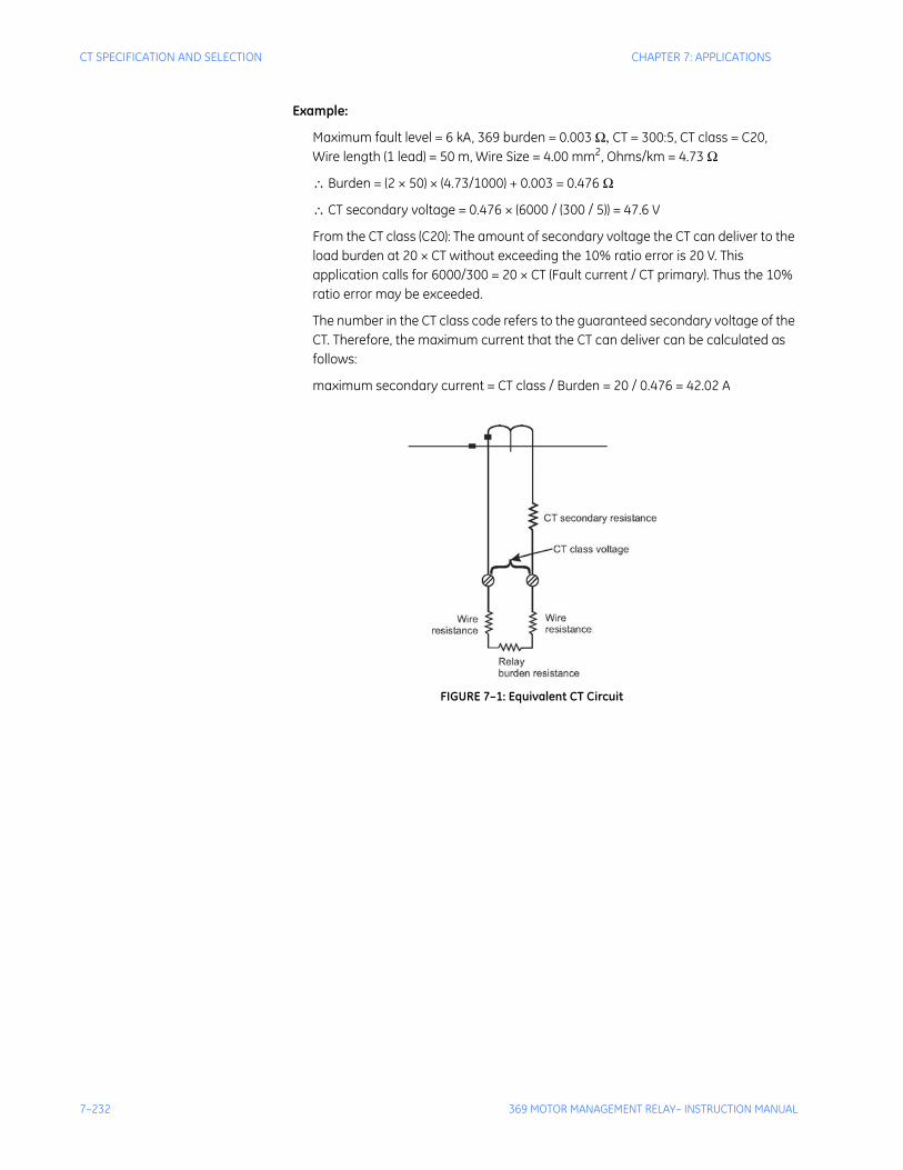
7–232 369 MOTOR MANAGEMENT RELAY– INSTRUCTION MANUAL
CT SPECIFICATION AND SELECTION CHAPTER 7: APPLICATIONS
Example:
Maximum fault level = 6 kA, 369 burden = 0.003 Ω, CT = 300:5, CT class = C20,Wire length (1 lead) = 50 m, Wire Size = 4.00 mm2, Ohms/km = 4.73 Ω
∴ Burden = (2 × 50) × (4.73/1000) + 0.003 = 0.476 Ω
∴ CT secondary voltage = 0.476 × (6000 / (300 / 5)) = 47.6 V
From the CT class (C20): The amount of secondary voltage the CT can deliver to the load burden at 20 × CT without exceeding the 10% ratio error is 20 V. This application calls for 6000/300 = 20 × CT (Fault current / CT primary). Thus the 10% ratio error may be exceeded.
The number in the CT class code refers to the guaranteed secondary voltage of the CT. Therefore, the maximum current that the CT can deliver can be calculated as follows:
maximum secondary current = CT class / Burden = 20 / 0.476 = 42.02 A
FIGURE 7–1: Equivalent CT Circuit
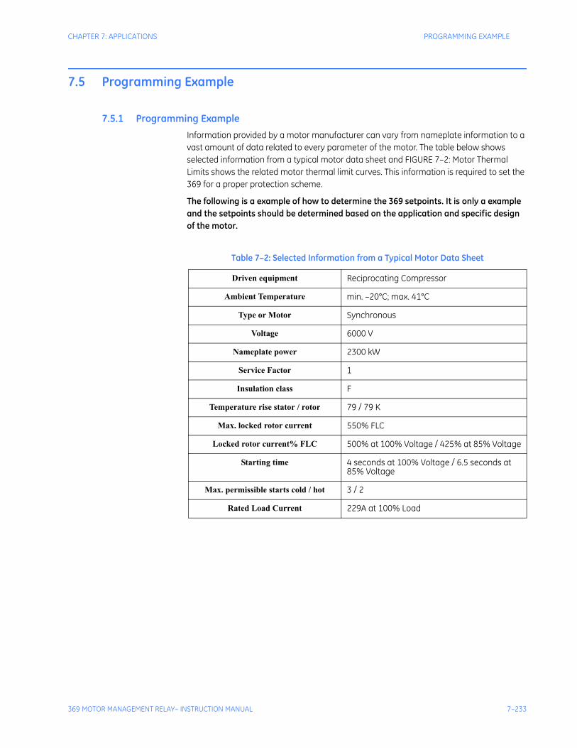
CHAPTER 7: APPLICATIONS PROGRAMMING EXAMPLE
369 MOTOR MANAGEMENT RELAY– INSTRUCTION MANUAL 7–233
7.5 Programming Example
7.5.1 Programming ExampleInformation provided by a motor manufacturer can vary from nameplate information to a vast amount of data related to every parameter of the motor. The table below shows selected information from a typical motor data sheet and FIGURE 7–2: Motor Thermal Limits shows the related motor thermal limit curves. This information is required to set the 369 for a proper protection scheme.
The following is a example of how to determine the 369 setpoints. It is only a example and the setpoints should be determined based on the application and specific design of the motor.
Table 7–2: Selected Information from a Typical Motor Data Sheet
Driven equipment Reciprocating Compressor
Ambient Temperature min. –20°C; max. 41°C
Type or Motor Synchronous
Voltage 6000 V
Nameplate power 2300 kW
Service Factor 1
Insulation class F
Temperature rise stator / rotor 79 / 79 K
Max. locked rotor current 550% FLC
Locked rotor current% FLC 500% at 100% Voltage / 425% at 85% Voltage
Starting time 4 seconds at 100% Voltage / 6.5 seconds at 85% Voltage
Max. permissible starts cold / hot 3 / 2
Rated Load Current 229A at 100% Load
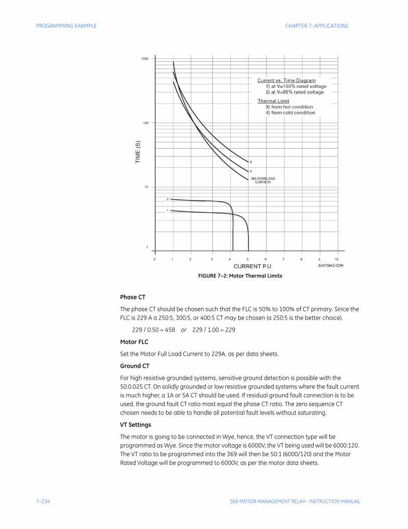
7–234 369 MOTOR MANAGEMENT RELAY– INSTRUCTION MANUAL
PROGRAMMING EXAMPLE CHAPTER 7: APPLICATIONS
FIGURE 7–2: Motor Thermal Limits
Phase CT
The phase CT should be chosen such that the FLC is 50% to 100% of CT primary. Since the FLC is 229 A a 250:5, 300:5, or 400:5 CT may be chosen (a 250:5 is the better choice).
229 / 0.50 = 458 or 229 / 1.00 = 229
Motor FLC
Set the Motor Full Load Current to 229A, as per data sheets.
Ground CT
For high resistive grounded systems, sensitive ground detection is possible with the 50:0.025 CT. On solidly grounded or low resistive grounded systems where the fault current is much higher, a 1A or 5A CT should be used. If residual ground fault connection is to be used, the ground fault CT ratio most equal the phase CT ratio. The zero sequence CT chosen needs to be able to handle all potential fault levels without saturating.
VT Settings
The motor is going to be connected in Wye, hence, the VT connection type will be programmed as Wye. Since the motor voltage is 6000V, the VT being used will be 6000:120. The VT ratio to be programmed into the 369 will then be 50:1 (6000/120) and the Motor Rated Voltage will be programmed to 6000V, as per the motor data sheets.
CHAPTER 7: APPLICATIONS PROGRAMMING EXAMPLE
369 MOTOR MANAGEMENT RELAY– INSTRUCTION MANUAL 7–235
Overload Pickup
The overload pickup is set to the same as the service factor of the motor. In this case, it would be set to the lowest setting of 1.01 x FLC for the service factor of 1.
Unbalance Bias Of Thermal Capacity
Enable the Unbalance Bias of Thermal Capacity so that the heating effect of unbalance currents is added to the Thermal Capacity Used.
Unbalance Bias K Factor
The K value is used to calculate the contribution of the negative sequence current flowing in the rotor due to unbalance. It is defined as:
, where: Rr2 = rotor negative sequence resistance, Rr1 = rotor positive sequence
resistance
where: LRA = Locked Rotor Current
Note The above formula is based on empirical data.
The 369 has the ability to learn the K value after five successful starts. After 5 starts, turn this setpoint off so that the 369 uses the learned value
Hot/Cold Curve Ratio
The hot/cold curve ratio is calculated by simply dividing the hot safe stall time by the cold safe stall time. This information can be extracted from the Thermal Limit curves. From FIGURE 7–2: Motor Thermal Limits, we can determine that the hot safe stall time is approximately 18 seconds and the cold safe stall time is approximately 24 seconds. Therefore, the Hot/Cold curve ratio should be programmed as 0.75 (18 / 24) for this example.
Running and Stopped Cool Time Constant
The running cool time is the time required for the motor to cool while running. This information is usually supplied by the motor manufacturer but is not part of the given data. The motor manufacturer should be contacted to find out what the cool times are.
The Thermal Capacity Used quantity decays exponentially to simulate the cooling of the motor. The rate of cooling is based upon the running cool time constant when the motor is running, or the stopped cool time constant when the motor is stopped. The entered cool time constant is one fifth the total cool time from 100% thermal capacity used down to 0% thermal capacity used.
The 369 has a unique capability of learning the cool time constant. This learned parameter is only functional if the Stator RTDs are connected to the 369. The learned cool time algorithm observes the temperature of the motor as it cools, thus determining the length of time required for cooling. If the cool times can not be retrieved from the motor manufacturer, then the Learned Cool Time must be enabled (if the stator RTDs are connected).
Rr2Rr1--------
K 175LRA
2---------- 175
5.52----------- 6@= =
7–236 369 MOTOR MANAGEMENT RELAY– INSTRUCTION MANUAL
PROGRAMMING EXAMPLE CHAPTER 7: APPLICATIONS
Motors have a fanning action when running due to the rotation of the rotor. For this reason, the running cool time is typically half of the stopped cool time.
Refer to the Selection of Cool Time application note for more details on how to determine the cool time constants when not provided with the motor.
RTD Biasing
This will enable the temperature from the Stator RTD sensors to be included in the calculations of Thermal Capacity. This model determines the Thermal Capacity Used based on the temperature of the Stators and is a separate calculation from the overload model for calculating Thermal Capacity Used. RTD biasing is a back up protection element which accounts for such things as loss of cooling or unusually high ambient temperature. There are three parameters to set: RTD Bias Min, RTD Bias Mid, RTD Bias Max.
RTD Bias Minimum
Set to 40°C which is the ambient temperature (obtained from data sheets).
RTD Bias Mid Point
The center point temperature is set to the motor’s hot running temperature and is calculated as follows:
Temperature Rise of Stator + Ambient Temperature.
The temperature rise of the stator is 79°K, obtained from the data sheets. Therefore, the RTD Center point temperature is set to 120°C (79 + 40).
RTD Bias Maximum
This setpoint is set to the rating of the insulation or slightly less. A class F insulation is used in this motor which is rated at 155°C.
Overload Curve
If only one thermal limit curve is provided, the chosen overload curve should fit below it. When a hot and cold thermal limit curve is provided, the chosen overload curve should fit between the two curves and the programmed Hot/Cold ratio is used in the Thermal Capacity algorithm to take into account the thermal state of the motor. The best fitting 369 standard curve is curve # 4, as seen in FIGURE 7–2: Motor Thermal Limits on page 7–234.
Short Circuit Trip
The short circuit trip should be set above the maximum locked rotor current but below the short circuit current of the fuses. The data sheets indicate a maximum locked rotor current of 550% FLC or 5.5 × FLC. A setting of 6 × FLC with a instantaneous time delay will be ideal but nuisance tripping may result due to unusually high demanding starts or starts while the load is coupled. If need be, set the S/C level higher to a maximum of 8 × FLC to override these conditions.
Mechanical Jam
If the process causes the motor to be prone to mechanical jams, set the Mechanical Jam Trip and Alarm accordingly. In most cases, the overload trip will become active before the Mechanical Trip, however, if a high overload curve is chosen, the Mechanical Jam level and time delay become more critical. The setting should then be set to below the overload curve but above any normal overload conditions of the motor. The main purpose of the mechanical jam element is to protect the driven equipment due to jammed, or broken equipment.

CHAPTER 7: APPLICATIONS PROGRAMMING EXAMPLE
369 MOTOR MANAGEMENT RELAY– INSTRUCTION MANUAL 7–237
Undercurrent
If detection of loss of load is required for the specific application, set the undercurrent element according to the current that will indicate loss of load. For example, this could be programmed for a pump application to detect loss of fluid in the pipe.
Unbalance Alarm and Trip
The unbalance settings are determined by examining the motor application and motor design. In this case, the motor being protected is a reciprocating compressor, in which unbalance will be a normal running condition, thus this setting should be set high. A setting of 20% for the Unbalance Alarm with a delay of 10 seconds would be appropriate and the trip may be set to 25% with a delay of 10 seconds
Ground Fault
Unfortunately, there is not enough information to determine a ground fault setting. These settings depend on the following information:
1. The Ground Fault current available.
2. System Grounding - high resistive grounding, solidly grounded, etc.
3. Ground Fault CT used.
4. Ground Fault connection - zero sequence or Residual connection.
Acceleration Trip
This setpoint should be set higher than the maximum starting time to avoid nuisance tripping when the voltage is lower or for varying loads during starting. If reduced voltage starting is used, a setting of 8 seconds would be appropriate, or if direct across the line starting is used, a setting of 5 seconds could be used.
Start Inhibit
This function should always be enabled after five successful starts to protect the motor during starting while it is already hot. The 369 learns the amount of thermal capacity used at start. If the motor is hot, thus having some thermal capacity, the 369 will not allow a start if the available thermal capacity is less than the required thermal capacity for a start. For more information regarding start inhibit refer to application note in section 7.6.6.
Starts/Hour
Starts/Hour can be set to the # of cold starts as per the data sheet. For this example, the starts/hour would be set to 3.
Time Between Starts
In some cases, the motor manufacturer will specify the time between motor starts. In this example, this information is not given so this feature can be turned “Off”. However, if the information is given, the time provided on the motor data sheets should be programmed.
Stator RTDs
RTD trip level should be set at or below the maximum temperature rating of the insulation. This example has a class F insulation which has a temperature rating of 155°C, therefore the Stator RTD Trip level should be set to between 140°C to 155°C. The RTD alarm level should be set to a level to provide a warning that the motor temperature is rising. For this example, 120°C or 130°C would be appropriate.

7–238 369 MOTOR MANAGEMENT RELAY– INSTRUCTION MANUAL
PROGRAMMING EXAMPLE CHAPTER 7: APPLICATIONS
Bearing RTDs
The Bearing RTD alarm and trip settings will be determined by evaluating the temperature specification from the bearing manufacturer.
CHAPTER 7: APPLICATIONS APPLICATIONS
369 MOTOR MANAGEMENT RELAY– INSTRUCTION MANUAL 7–239
7.6 Applications
7.6.1 Motor Status DetectionThe 369 detects a stopped motor condition when the phase current falls below 5% of CT, and detects a starting motor condition when phase current is sensed after a stopped motor condition. If the motor idles at 5% of CT, several starts and stops can be detected causing nuisance lockouts if Starts/Hour, Time Between Starts, Restart Block, Start Inhibit, or Backspin Timer are programmed. As well, the learned values, such as the Learned Starting Thermal Capacity, Learned Starting Current and Learned Acceleration time can be incorrectly calculated.
To overcome this potential problem, the Spare Digital Input can be configured to read the status of the breaker and determine whether the motor is stopped or simply idling. With the spare input configured as Starter Status and the breaker auxiliary contacts wired across the spare input terminals, the 369 senses a stopped motor condition only when the phase current is below 5% of CT (or zero) AND the breaker is open. If both of these conditions are not met, the 369 will continue to operate as if the motor is running and the starting elements remain unchanged. Refer to the flowchart below for details of how the 369 detects motor status and how the starter status element further defines the condition of the motor.
When the Starter Status is programmed, the type of breaker contact being used for monitoring must be set. The following are the states of the breaker auxiliary contacts in relation to the breaker:
• 52a, 52aa - open when the breaker contacts are open and closed when the breaker contacts are closed
• 52b, 52bb - closed when the breaker contacts are open and open when the breaker contacts are closed
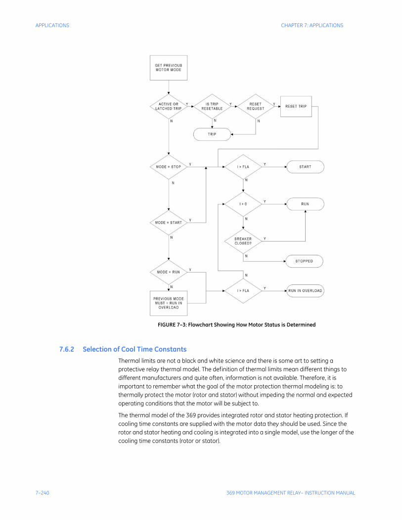
7–240 369 MOTOR MANAGEMENT RELAY– INSTRUCTION MANUAL
APPLICATIONS CHAPTER 7: APPLICATIONS
FIGURE 7–3: Flowchart Showing How Motor Status is Determined
7.6.2 Selection of Cool Time ConstantsThermal limits are not a black and white science and there is some art to setting a protective relay thermal model. The definition of thermal limits mean different things to different manufacturers and quite often, information is not available. Therefore, it is important to remember what the goal of the motor protection thermal modeling is: to thermally protect the motor (rotor and stator) without impeding the normal and expected operating conditions that the motor will be subject to.
The thermal model of the 369 provides integrated rotor and stator heating protection. If cooling time constants are supplied with the motor data they should be used. Since the rotor and stator heating and cooling is integrated into a single model, use the longer of the cooling time constants (rotor or stator).
CHAPTER 7: APPLICATIONS APPLICATIONS
369 MOTOR MANAGEMENT RELAY– INSTRUCTION MANUAL 7–241
If however, no cooling time constants are provided, settings will have to be determined. Before determining the cool time constant settings, the duty cycle of the motor should be considered. If the motor is typically started and run continuously for very long periods of time with no overload duty requirements, the cooling time constants can be large. This would make the thermal model conservative. If the normal duty cycle of the motor involves frequent starts and stops with a periodic overload duty requirement, the cooling time constants will need to be shorter and closer to the actual thermal limit of the motor.
Normally motors are rotor limited during starting. Thus RTDs in the stator do not provide the best method of determining cool times. Determination of reasonable settings for the running and stopped cool time constants can be accomplished in one of the following manners listed in order of preference.
1. The motor running and stopped cool times or constants may be provided on the motor data sheets or by the manufacturer if requested. Remember that the cooling is exponential and the time constants are one fifth the total time to go from 100% thermal capacity used to 0%.
2. Attempt to determine a conservative value from available data on the motor. See the following example for details.
3. If no data is available an educated guess must be made. Perhaps the motor data could be estimated from other motors of a similar size or use. Note that conservative protection is better as a first choice until a better understanding of the motor requirements is developed. Remember that the goal is to protect the motor without impeding the operating duty that is desired.
Example:
Motor data sheets state that the starting sequence allowed is 2 cold or 1 hot after which you must wait 5 hours before attempting another start.
• This implies that under a normal start condition the motor is using between 34 and 50% thermal capacity. Hence, two consecutive starts are allowed, but not three (i.e. 34 × 3 > 100).
• If the hot and cold curves or a hot/cold safe stall ratio are not available program 0.5 (1 hot / 2 cold starts) in as the hot/cold ratio.
• Programming Start Inhibit ‘On’ makes a restart possible as soon as 62.5% (50 × 1.25) thermal capacity is available.
• After 2 cold or 1 hot start, close to 100% thermal capacity will be used. Thermal capacity used decays exponentially (see 369 manual section on motor cooling for calculation). There will be only 37% thermal capacity used after 1 time constant which means there is enough thermal capacity available for another start. Program 60 minutes (5 hours) as the stopped cool time constant . Thus after 2 cold or 1 hot start, a stopped motor will be blocked from starting for 5 hours.
Since the rotor cools faster when the motor is running, a reasonable setting for the running cool time constant might be half the stopped cool time constant or 150 minutes.
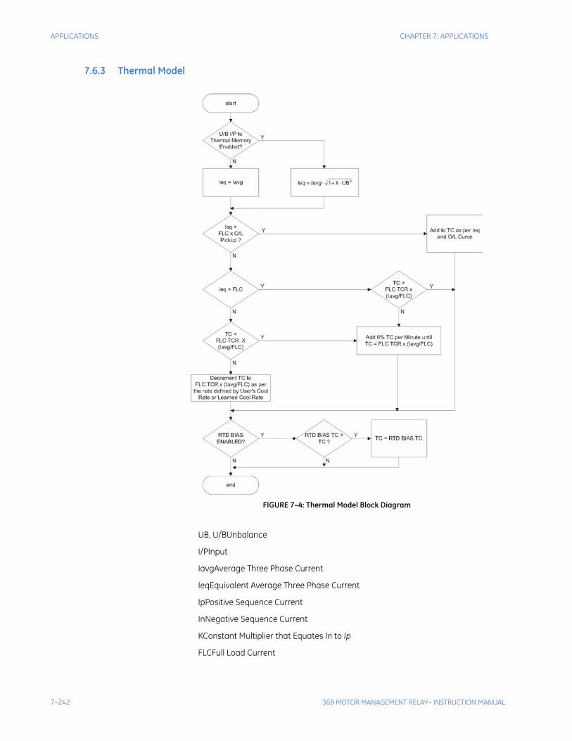
7–242 369 MOTOR MANAGEMENT RELAY– INSTRUCTION MANUAL
APPLICATIONS CHAPTER 7: APPLICATIONS
7.6.3 Thermal Model
FIGURE 7–4: Thermal Model Block Diagram
UB, U/BUnbalance
I/PInput
IavgAverage Three Phase Current
IeqEquivalent Average Three Phase Current
IpPositive Sequence Current
InNegative Sequence Current
KConstant Multiplier that Equates In to Ip
FLCFull Load Current
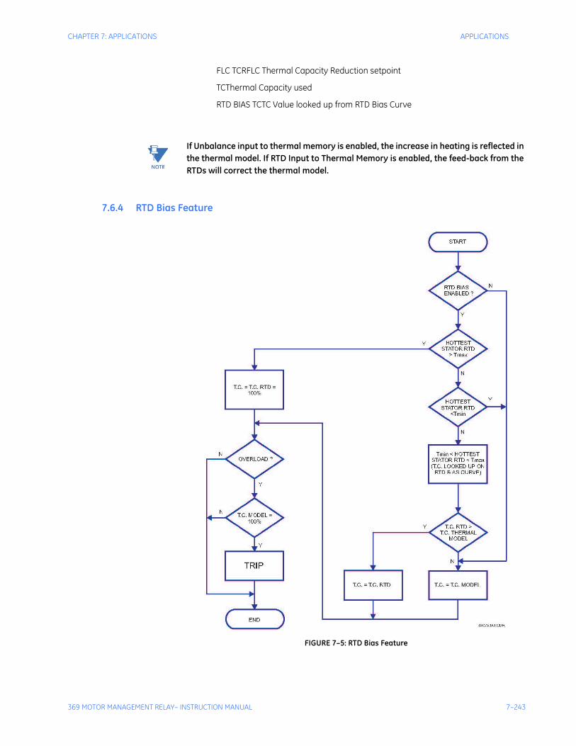
CHAPTER 7: APPLICATIONS APPLICATIONS
369 MOTOR MANAGEMENT RELAY– INSTRUCTION MANUAL 7–243
FLC TCRFLC Thermal Capacity Reduction setpoint
TCThermal Capacity used
RTD BIAS TCTC Value looked up from RTD Bias Curve
Note If Unbalance input to thermal memory is enabled, the increase in heating is reflected in the thermal model. If RTD Input to Thermal Memory is enabled, the feed-back from the RTDs will correct the thermal model.
7.6.4 RTD Bias Feature
FIGURE 7–5: RTD Bias Feature
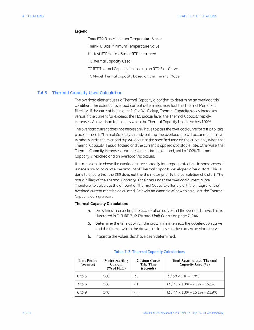
7–244 369 MOTOR MANAGEMENT RELAY– INSTRUCTION MANUAL
APPLICATIONS CHAPTER 7: APPLICATIONS
Legend
TmaxRTD Bias Maximum Temperature Value
TminRTD Bias Minimum Temperature Value
Hottest RTDHottest Stator RTD measured
TCThermal Capacity Used
TC RTDThermal Capacity Looked up on RTD Bias Curve.
TC ModelThermal Capacity based on the Thermal Model
7.6.5 Thermal Capacity Used CalculationThe overload element uses a Thermal Capacity algorithm to determine an overload trip condition. The extent of overload current determines how fast the Thermal Memory is filled, i.e. if the current is just over FLC × O/L Pickup, Thermal Capacity slowly increases; versus if the current far exceeds the FLC pickup level, the Thermal Capacity rapidly increases. An overload trip occurs when the Thermal Capacity Used reaches 100%.
The overload current does not necessarily have to pass the overload curve for a trip to take place. If there is Thermal Capacity already built up, the overload trip will occur much faster. In other words, the overload trip will occur at the specified time on the curve only when the Thermal Capacity is equal to zero and the current is applied at a stable rate. Otherwise, the Thermal Capacity increases from the value prior to overload, until a 100% Thermal Capacity is reached and an overload trip occurs.
It is important to chose the overload curve correctly for proper protection. In some cases it is necessary to calculate the amount of Thermal Capacity developed after a start. This is done to ensure that the 369 does not trip the motor prior to the completion of a start. The actual filling of the Thermal Capacity is the area under the overload current curve. Therefore, to calculate the amount of Thermal Capacity after a start, the integral of the overload current most be calculated. Below is an example of how to calculate the Thermal Capacity during a start:
Thermal Capacity Calculation:
4. Draw lines intersecting the acceleration curve and the overload curve. This is illustrated in FIGURE 7–6: Thermal Limit Curves on page 7–246.
5. Determine the time at which the drawn line intersect, the acceleration curve and the time at which the drawn line intersects the chosen overload curve.
6. Integrate the values that have been determined.
Table 7–3: Thermal Capacity Calculations
Time Period(seconds)
Motor Starting Current
(% of FLC)
Custom Curve Trip Time (seconds)
Total Accumulated ThermalCapacity Used (%)
0 to 3 580 38 3 / 38 × 100 = 7.8%
3 to 6 560 41 (3 / 41 × 100) + 7.8% = 15.1%
6 to 9 540 44 (3 / 44 × 100) + 15.1% = 21.9%
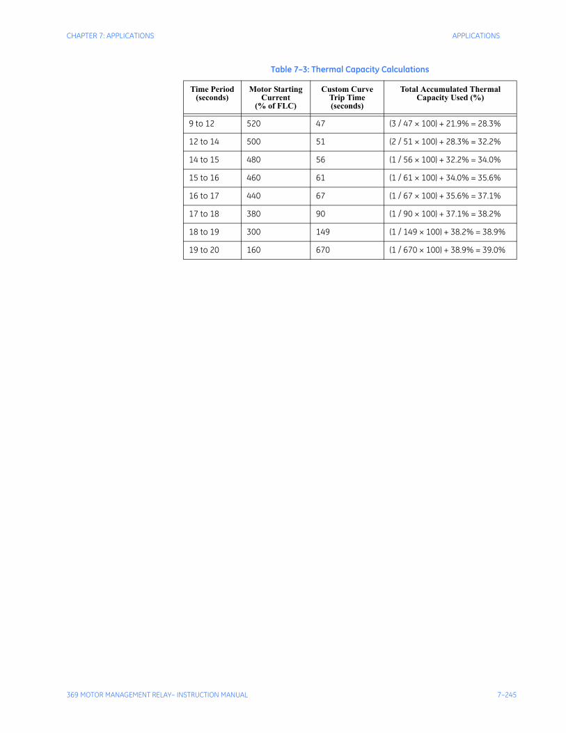
CHAPTER 7: APPLICATIONS APPLICATIONS
369 MOTOR MANAGEMENT RELAY– INSTRUCTION MANUAL 7–245
9 to 12 520 47 (3 / 47 × 100) + 21.9% = 28.3%
12 to 14 500 51 (2 / 51 × 100) + 28.3% = 32.2%
14 to 15 480 56 (1 / 56 × 100) + 32.2% = 34.0%
15 to 16 460 61 (1 / 61 × 100) + 34.0% = 35.6%
16 to 17 440 67 (1 / 67 × 100) + 35.6% = 37.1%
17 to 18 380 90 (1 / 90 × 100) + 37.1% = 38.2%
18 to 19 300 149 (1 / 149 × 100) + 38.2% = 38.9%
19 to 20 160 670 (1 / 670 × 100) + 38.9% = 39.0%
Table 7–3: Thermal Capacity Calculations
Time Period(seconds)
Motor Starting Current
(% of FLC)
Custom Curve Trip Time (seconds)
Total Accumulated ThermalCapacity Used (%)
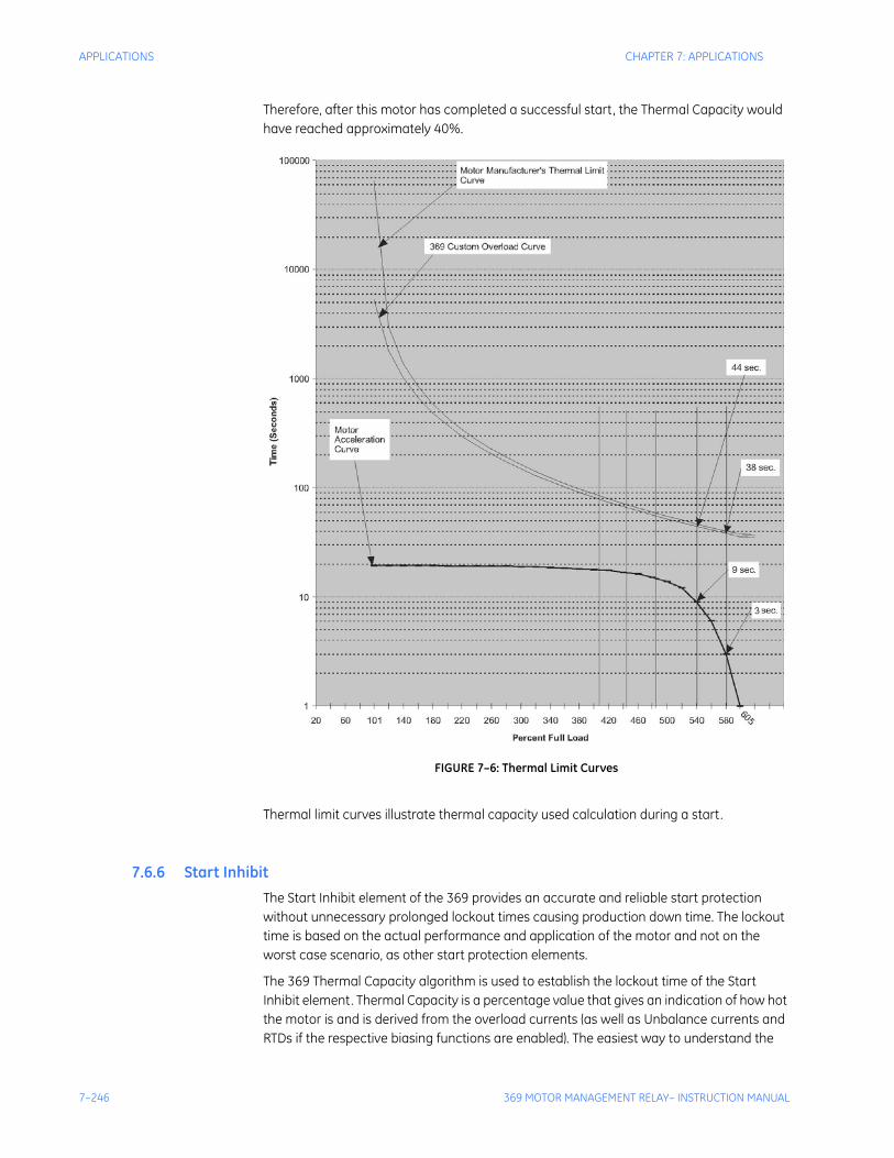
7–246 369 MOTOR MANAGEMENT RELAY– INSTRUCTION MANUAL
APPLICATIONS CHAPTER 7: APPLICATIONS
Therefore, after this motor has completed a successful start, the Thermal Capacity would have reached approximately 40%.
FIGURE 7–6: Thermal Limit Curves
Thermal limit curves illustrate thermal capacity used calculation during a start.
7.6.6 Start InhibitThe Start Inhibit element of the 369 provides an accurate and reliable start protection without unnecessary prolonged lockout times causing production down time. The lockout time is based on the actual performance and application of the motor and not on the worst case scenario, as other start protection elements.
The 369 Thermal Capacity algorithm is used to establish the lockout time of the Start Inhibit element. Thermal Capacity is a percentage value that gives an indication of how hot the motor is and is derived from the overload currents (as well as Unbalance currents and RTDs if the respective biasing functions are enabled). The easiest way to understand the
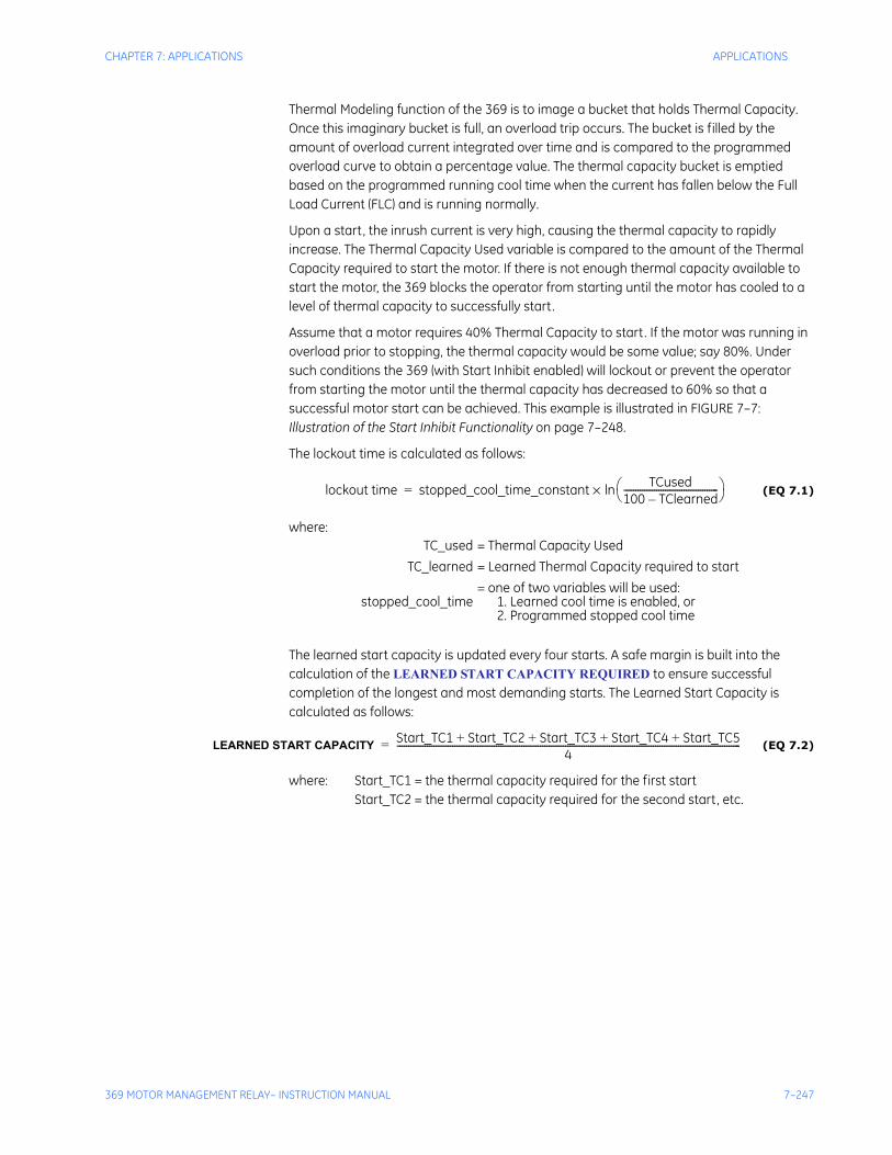
CHAPTER 7: APPLICATIONS APPLICATIONS
369 MOTOR MANAGEMENT RELAY– INSTRUCTION MANUAL 7–247
Thermal Modeling function of the 369 is to image a bucket that holds Thermal Capacity. Once this imaginary bucket is full, an overload trip occurs. The bucket is filled by the amount of overload current integrated over time and is compared to the programmed overload curve to obtain a percentage value. The thermal capacity bucket is emptied based on the programmed running cool time when the current has fallen below the Full Load Current (FLC) and is running normally.
Upon a start, the inrush current is very high, causing the thermal capacity to rapidly increase. The Thermal Capacity Used variable is compared to the amount of the Thermal Capacity required to start the motor. If there is not enough thermal capacity available to start the motor, the 369 blocks the operator from starting until the motor has cooled to a level of thermal capacity to successfully start.
Assume that a motor requires 40% Thermal Capacity to start. If the motor was running in overload prior to stopping, the thermal capacity would be some value; say 80%. Under such conditions the 369 (with Start Inhibit enabled) will lockout or prevent the operator from starting the motor until the thermal capacity has decreased to 60% so that a successful motor start can be achieved. This example is illustrated in FIGURE 7–7: Illustration of the Start Inhibit Functionality on page 7–248.
The lockout time is calculated as follows:
(EQ 7.1)
where:
The learned start capacity is updated every four starts. A safe margin is built into the calculation of the LEARNED START CAPACITY REQUIRED to ensure successful completion of the longest and most demanding starts. The Learned Start Capacity is calculated as follows:
(EQ 7.2)
where: Start_TC1 = the thermal capacity required for the first startStart_TC2 = the thermal capacity required for the second start, etc.
TC_used = Thermal Capacity Used TC_learned = Learned Thermal Capacity required to start
stopped_cool_time= one of two variables will be used:
1. Learned cool time is enabled, or2. Programmed stopped cool time
lockout time stopped_cool_time_constant TCused100 TClearned–-----------------------------------------⎝ ⎠⎛ ⎞ln×=
LEARNED START CAPACITY Start_TC1 Start_TC2 Start_TC3 Start_TC4 Start_TC5+ + + +4
-----------------------------------------------------------------------------------------------------------------------------------------------------=
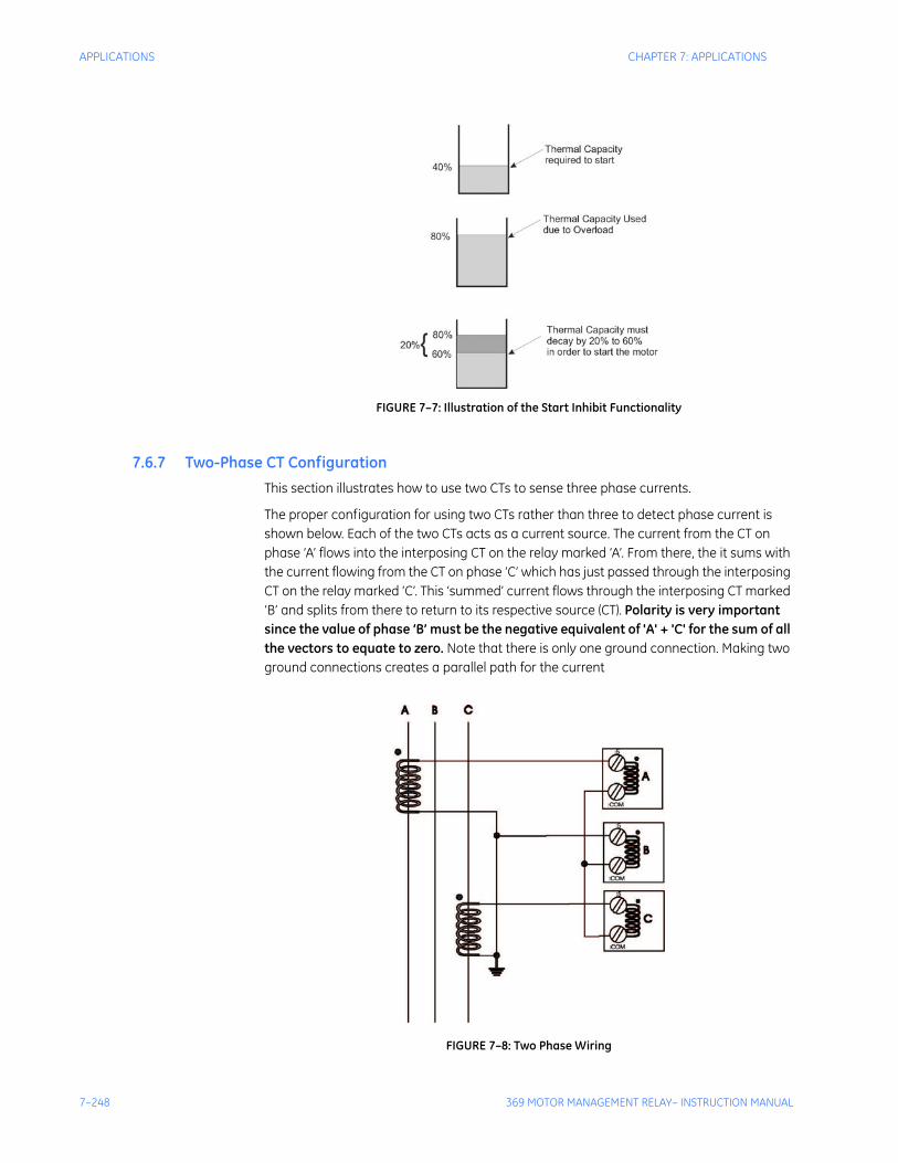
7–248 369 MOTOR MANAGEMENT RELAY– INSTRUCTION MANUAL
APPLICATIONS CHAPTER 7: APPLICATIONS
FIGURE 7–7: Illustration of the Start Inhibit Functionality
7.6.7 Two-Phase CT ConfigurationThis section illustrates how to use two CTs to sense three phase currents.
The proper configuration for using two CTs rather than three to detect phase current is shown below. Each of the two CTs acts as a current source. The current from the CT on phase ‘A’ flows into the interposing CT on the relay marked ‘A’. From there, the it sums with the current flowing from the CT on phase ‘C’ which has just passed through the interposing CT on the relay marked ‘C’. This ‘summed’ current flows through the interposing CT marked ‘B’ and splits from there to return to its respective source (CT). Polarity is very important since the value of phase ‘B’ must be the negative equivalent of 'A' + 'C' for the sum of all the vectors to equate to zero. Note that there is only one ground connection. Making two ground connections creates a parallel path for the current
FIGURE 7–8: Two Phase Wiring
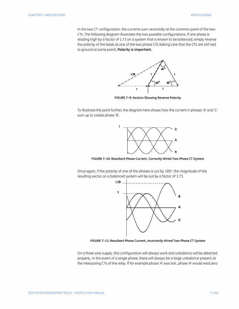
CHAPTER 7: APPLICATIONS APPLICATIONS
369 MOTOR MANAGEMENT RELAY– INSTRUCTION MANUAL 7–249
In the two CT configuration, the currents sum vectorially at the common point of the two CTs. The following diagram illustrates the two possible configurations. If one phase is reading high by a factor of 1.73 on a system that is known to be balanced, simply reverse the polarity of the leads at one of the two phase CTs (taking care that the CTs are still tied to ground at some point). Polarity is important.
FIGURE 7–9: Vectors Showing Reverse Polarity
To illustrate the point further, the diagram here shows how the current in phases 'A' and 'C' sum up to create phase 'B'.
FIGURE 7–10: Resultant Phase Current, Correctly Wired Two-Phase CT System
Once again, if the polarity of one of the phases is out by 180°, the magnitude of the resulting vector on a balanced system will be out by a factor of 1.73.
FIGURE 7–11: Resultant Phase Current, Incorrectly Wired Two-Phase CT System
On a three wire supply, this configuration will always work and unbalance will be detected properly. In the event of a single phase, there will always be a large unbalance present at the interposing CTs of the relay. If for example phase ‘A’ was lost, phase ‘A’ would read zero
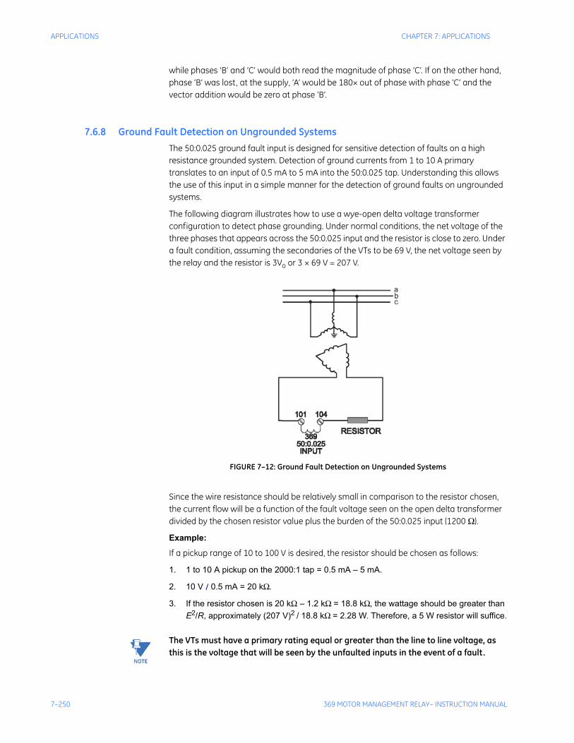
7–250 369 MOTOR MANAGEMENT RELAY– INSTRUCTION MANUAL
APPLICATIONS CHAPTER 7: APPLICATIONS
while phases ‘B’ and ‘C’ would both read the magnitude of phase ‘C’. If on the other hand, phase ‘B’ was lost, at the supply, ‘A’ would be 180× out of phase with phase ‘C’ and the vector addition would be zero at phase ‘B’.
7.6.8 Ground Fault Detection on Ungrounded SystemsThe 50:0.025 ground fault input is designed for sensitive detection of faults on a high resistance grounded system. Detection of ground currents from 1 to 10 A primary translates to an input of 0.5 mA to 5 mA into the 50:0.025 tap. Understanding this allows the use of this input in a simple manner for the detection of ground faults on ungrounded systems.
The following diagram illustrates how to use a wye-open delta voltage transformer configuration to detect phase grounding. Under normal conditions, the net voltage of the three phases that appears across the 50:0.025 input and the resistor is close to zero. Under a fault condition, assuming the secondaries of the VTs to be 69 V, the net voltage seen by the relay and the resistor is 3Vo or 3 × 69 V = 207 V.
FIGURE 7–12: Ground Fault Detection on Ungrounded Systems
Since the wire resistance should be relatively small in comparison to the resistor chosen, the current flow will be a function of the fault voltage seen on the open delta transformer divided by the chosen resistor value plus the burden of the 50:0.025 input (1200 Ω).
Example:
If a pickup range of 10 to 100 V is desired, the resistor should be chosen as follows:
1. 1 to 10 A pickup on the 2000:1 tap = 0.5 mA – 5 mA.
2. 10 V / 0.5 mA = 20 kΩ.
3. If the resistor chosen is 20 kΩ – 1.2 kΩ = 18.8 kΩ, the wattage should be greater than E2/R, approximately (207 V)2 / 18.8 kΩ = 2.28 W. Therefore, a 5 W resistor will suffice.
Note The VTs must have a primary rating equal or greater than the line to line voltage, as this is the voltage that will be seen by the unfaulted inputs in the event of a fault.
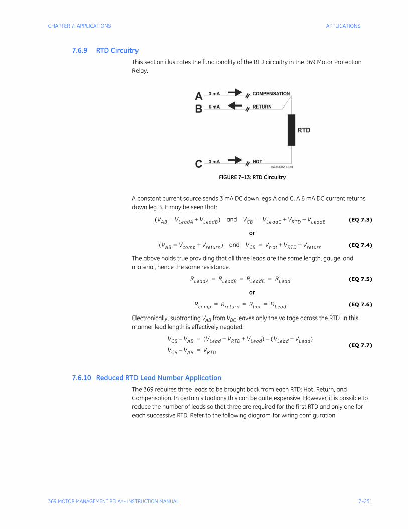
CHAPTER 7: APPLICATIONS APPLICATIONS
369 MOTOR MANAGEMENT RELAY– INSTRUCTION MANUAL 7–251
7.6.9 RTD CircuitryThis section illustrates the functionality of the RTD circuitry in the 369 Motor Protection Relay.
FIGURE 7–13: RTD Circuitry
A constant current source sends 3 mA DC down legs A and C. A 6 mA DC current returns down leg B. It may be seen that:
(EQ 7.3)
or
(EQ 7.4)
The above holds true providing that all three leads are the same length, gauge, and material, hence the same resistance.
(EQ 7.5)
or
(EQ 7.6)
Electronically, subtracting VAB from VBC leaves only the voltage across the RTD. In this manner lead length is effectively negated:
(EQ 7.7)
7.6.10 Reduced RTD Lead Number ApplicationThe 369 requires three leads to be brought back from each RTD: Hot, Return, and Compensation. In certain situations this can be quite expensive. However, it is possible to reduce the number of leads so that three are required for the first RTD and only one for each successive RTD. Refer to the following diagram for wiring configuration.
VAB VLeadA VLeadB+=( ) and VCB VLeadC VRTD VLeadB+ +=
VAB Vcomp Vreturn+=( ) and VCB Vhot VRTD Vreturn+ +=
RLeadA RLeadB RLeadC RLead= = =
Rcomp Rreturn Rhot RLead= = =
VCB VAB– VLead VRTD VLead+ +( ) VLead VLead+( )–=
VCB VAB– VRTD=
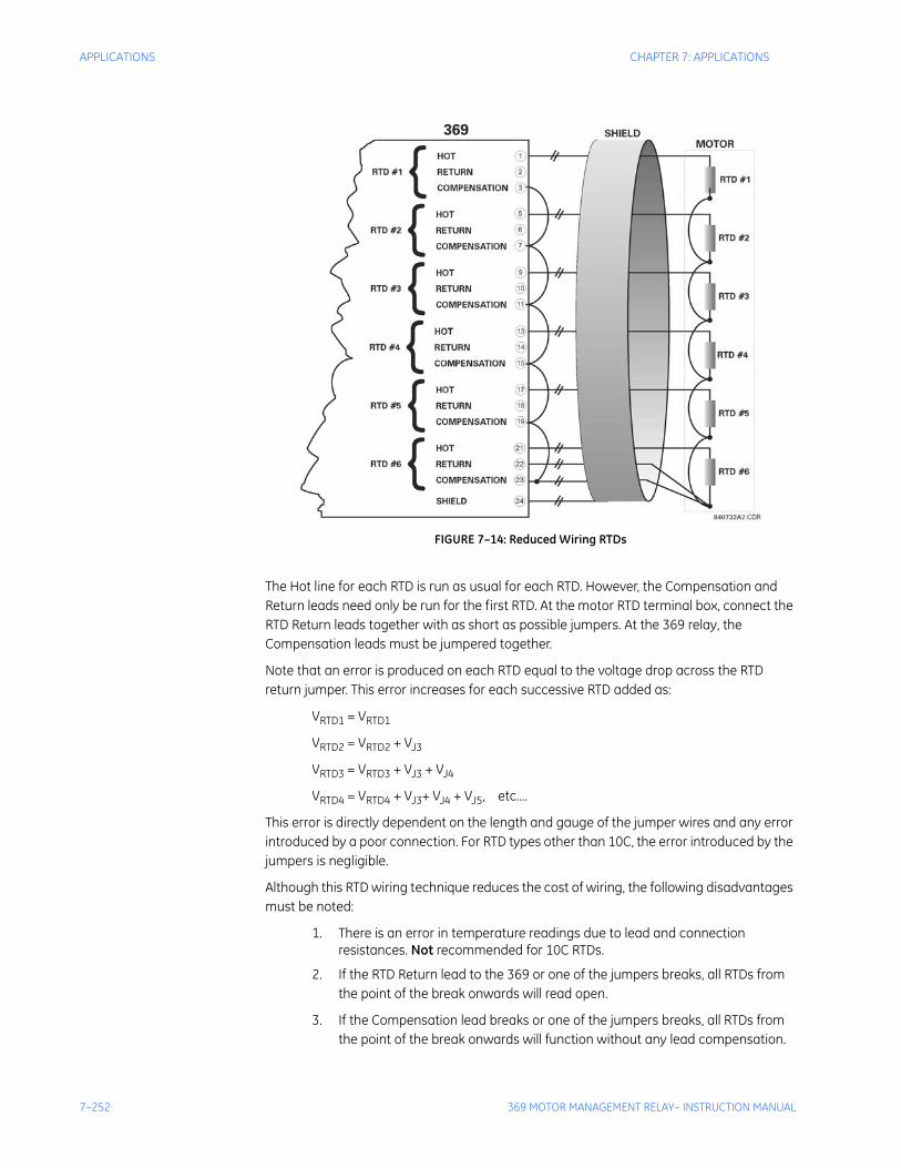
7–252 369 MOTOR MANAGEMENT RELAY– INSTRUCTION MANUAL
APPLICATIONS CHAPTER 7: APPLICATIONS
FIGURE 7–14: Reduced Wiring RTDs
The Hot line for each RTD is run as usual for each RTD. However, the Compensation and Return leads need only be run for the first RTD. At the motor RTD terminal box, connect the RTD Return leads together with as short as possible jumpers. At the 369 relay, the Compensation leads must be jumpered together.
Note that an error is produced on each RTD equal to the voltage drop across the RTD return jumper. This error increases for each successive RTD added as:
VRTD1 = VRTD1
VRTD2 = VRTD2 + VJ3
VRTD3 = VRTD3 + VJ3 + VJ4
VRTD4 = VRTD4 + VJ3+ VJ4 + VJ5, etc....
This error is directly dependent on the length and gauge of the jumper wires and any error introduced by a poor connection. For RTD types other than 10C, the error introduced by the jumpers is negligible.
Although this RTD wiring technique reduces the cost of wiring, the following disadvantages must be noted:
1. There is an error in temperature readings due to lead and connection resistances. Not recommended for 10C RTDs.
2. If the RTD Return lead to the 369 or one of the jumpers breaks, all RTDs from the point of the break onwards will read open.
3. If the Compensation lead breaks or one of the jumpers breaks, all RTDs from the point of the break onwards will function without any lead compensation.
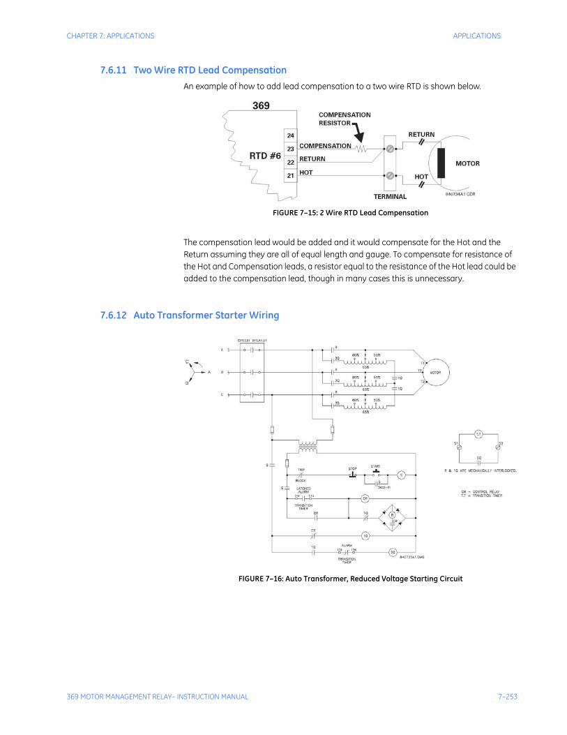
CHAPTER 7: APPLICATIONS APPLICATIONS
369 MOTOR MANAGEMENT RELAY– INSTRUCTION MANUAL 7–253
7.6.11 Two Wire RTD Lead CompensationAn example of how to add lead compensation to a two wire RTD is shown below.
FIGURE 7–15: 2 Wire RTD Lead Compensation
The compensation lead would be added and it would compensate for the Hot and the Return assuming they are all of equal length and gauge. To compensate for resistance of the Hot and Compensation leads, a resistor equal to the resistance of the Hot lead could be added to the compensation lead, though in many cases this is unnecessary.
7.6.12 Auto Transformer Starter Wiring
FIGURE 7–16: Auto Transformer, Reduced Voltage Starting Circuit

7–254 369 MOTOR MANAGEMENT RELAY– INSTRUCTION MANUAL
APPLICATIONS CHAPTER 7: APPLICATIONS

369 MOTOR MANAGEMENT RELAY– INSTRUCTION MANUAL 8–255
369 Motor Management Relay
Chapter 8: Testing
Digital EnergyMultilin
Testing
8.1 Test Setup
8.1.1 IntroductionThis chapter demonstrates the procedures necessary to perform a complete functional test of all the 369 hardware while also testing firmware/hardware interaction in the process. Testing of the relay during commissioning using a primary injection test set will ensure that CTs and wiring are correct and complete.
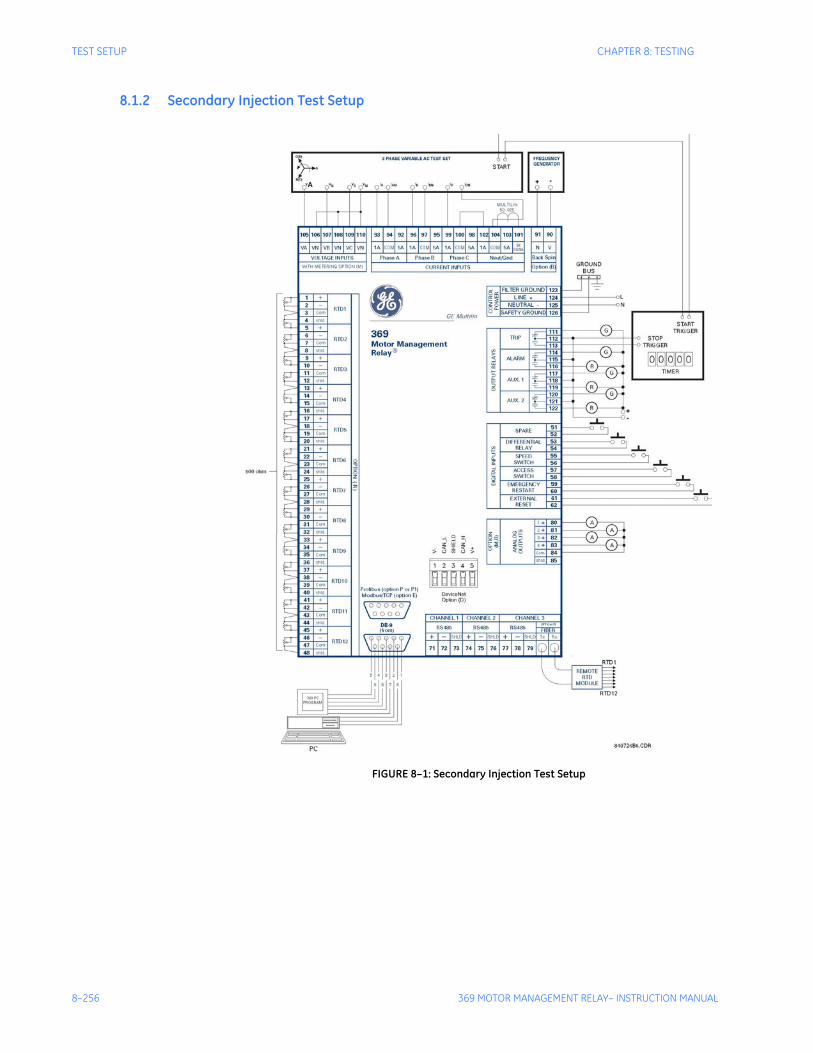
8–256 369 MOTOR MANAGEMENT RELAY– INSTRUCTION MANUAL
TEST SETUP CHAPTER 8: TESTING
8.1.2 Secondary Injection Test Setup
FIGURE 8–1: Secondary Injection Test Setup
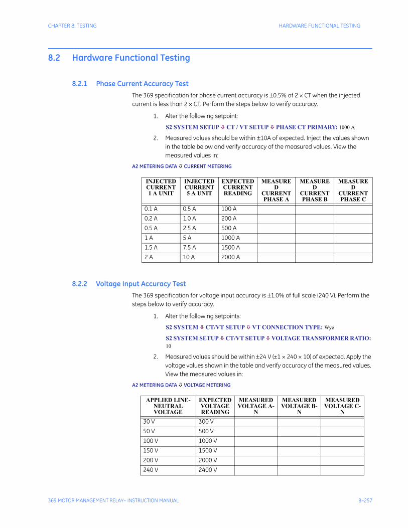
CHAPTER 8: TESTING HARDWARE FUNCTIONAL TESTING
369 MOTOR MANAGEMENT RELAY– INSTRUCTION MANUAL 8–257
8.2 Hardware Functional Testing
8.2.1 Phase Current Accuracy TestThe 369 specification for phase current accuracy is ±0.5% of 2 × CT when the injected current is less than 2 × CT. Perform the steps below to verify accuracy.
1. Alter the following setpoint:
S2 SYSTEM SETUP CT / VT SETUP PHASE CT PRIMARY: 1000 A
2. Measured values should be within ±10A of expected. Inject the values shown in the table below and verify accuracy of the measured values. View the measured values in:
A2 METERING DATA CURRENT METERING
8.2.2 Voltage Input Accuracy TestThe 369 specification for voltage input accuracy is ±1.0% of full scale (240 V). Perform the steps below to verify accuracy.
1. Alter the following setpoints:
S2 SYSTEM CT/VT SETUP VT CONNECTION TYPE: Wye
S2 SYSTEM SETUP CT/VT SETUP VOLTAGE TRANSFORMER RATIO: 10
2. Measured values should be within ±24 V (±1 × 240 × 10) of expected. Apply the voltage values shown in the table and verify accuracy of the measured values. View the measured values in:
A2 METERING DATA VOLTAGE METERING
INJECTED CURRENT 1 A UNIT
INJECTED CURRENT 5 A UNIT
EXPECTED CURRENT READING
MEASURED
CURRENT PHASE A
MEASURED
CURRENT PHASE B
MEASURED
CURRENT PHASE C
0.1 A 0.5 A 100 A0.2 A 1.0 A 200 A0.5 A 2.5 A 500 A1 A 5 A 1000 A1.5 A 7.5 A 1500 A2 A 10 A 2000 A
APPLIED LINE-NEUTRAL VOLTAGE
EXPECTED VOLTAGE READING
MEASURED VOLTAGE A-
N
MEASURED VOLTAGE B-
N
MEASURED VOLTAGE C-
N30 V 300 V50 V 500 V100 V 1000 V150 V 1500 V200 V 2000 V240 V 2400 V
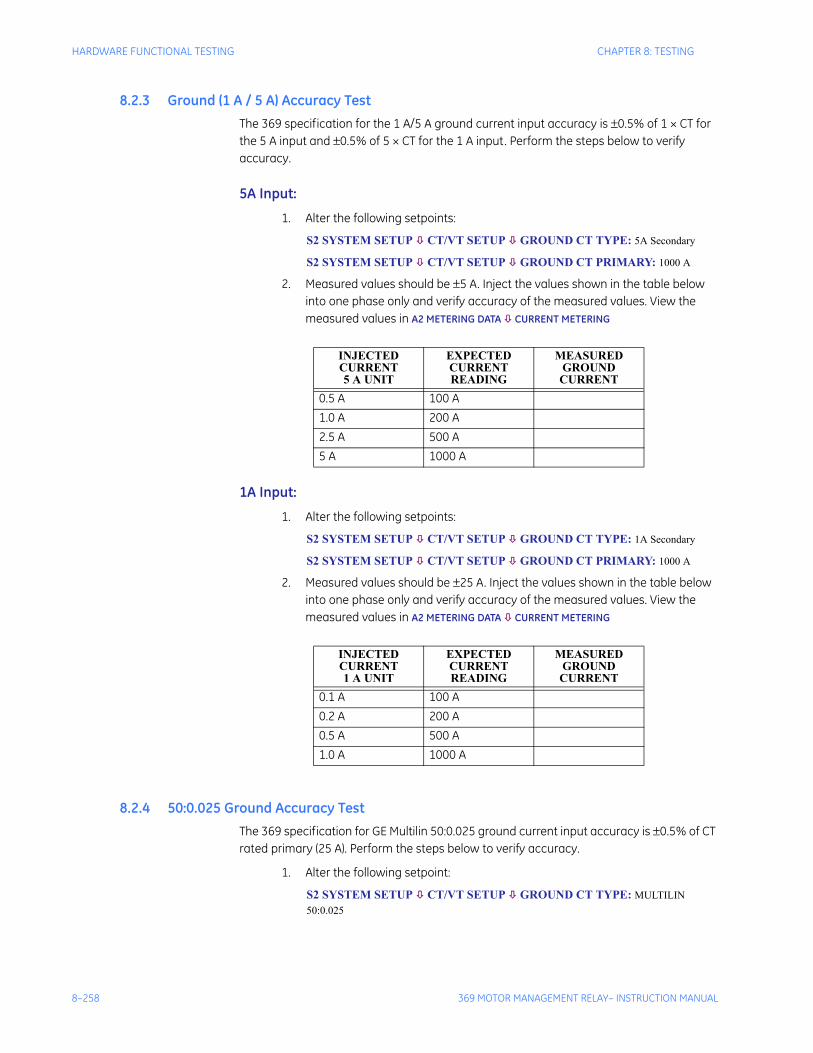
8–258 369 MOTOR MANAGEMENT RELAY– INSTRUCTION MANUAL
HARDWARE FUNCTIONAL TESTING CHAPTER 8: TESTING
8.2.3 Ground (1 A / 5 A) Accuracy TestThe 369 specification for the 1 A/5 A ground current input accuracy is ±0.5% of 1 × CT for the 5 A input and ±0.5% of 5 × CT for the 1 A input. Perform the steps below to verify accuracy.
5A Input:
1. Alter the following setpoints:
S2 SYSTEM SETUP CT/VT SETUP GROUND CT TYPE: 5A Secondary
S2 SYSTEM SETUP CT/VT SETUP GROUND CT PRIMARY: 1000 A
2. Measured values should be ±5 A. Inject the values shown in the table below into one phase only and verify accuracy of the measured values. View the measured values in A2 METERING DATA CURRENT METERING
1A Input:
1. Alter the following setpoints:
S2 SYSTEM SETUP CT/VT SETUP GROUND CT TYPE: 1A Secondary
S2 SYSTEM SETUP CT/VT SETUP GROUND CT PRIMARY: 1000 A
2. Measured values should be ±25 A. Inject the values shown in the table below into one phase only and verify accuracy of the measured values. View the measured values in A2 METERING DATA CURRENT METERING
8.2.4 50:0.025 Ground Accuracy TestThe 369 specification for GE Multilin 50:0.025 ground current input accuracy is ±0.5% of CT rated primary (25 A). Perform the steps below to verify accuracy.
1. Alter the following setpoint:
S2 SYSTEM SETUP CT/VT SETUP GROUND CT TYPE: MULTILIN 50:0.025
INJECTED CURRENT5 A UNIT
EXPECTEDCURRENTREADING
MEASUREDGROUNDCURRENT
0.5 A 100 A1.0 A 200 A2.5 A 500 A5 A 1000 A
INJECTEDCURRENT1 A UNIT
EXPECTEDCURRENTREADING
MEASUREDGROUNDCURRENT
0.1 A 100 A0.2 A 200 A0.5 A 500 A1.0 A 1000 A
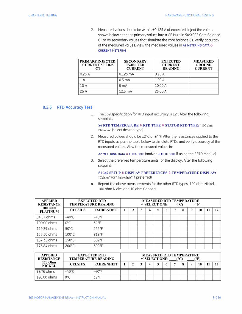
CHAPTER 8: TESTING HARDWARE FUNCTIONAL TESTING
369 MOTOR MANAGEMENT RELAY– INSTRUCTION MANUAL 8–259
2. Measured values should be within ±0.125 A of expected. Inject the values shown below either as primary values into a GE Multilin 50:0.025 Core Balance CT or as secondary values that simulate the core balance CT. Verify accuracy of the measured values. View the measured values in A2 METERING DATA
CURRENT METERING
8.2.5 RTD Accuracy Test1. The 369 specification for RTD input accuracy is ±2°. Alter the following
setpoints:
S6 RTD TEMPERATURE RTD TYPE STATOR RTD TYPE: “100 ohm Platinum” (select desired type)
2. Measured values should be ±2°C or ±4°F. Alter the resistances applied to the RTD inputs as per the table below to simulate RTDs and verify accuracy of the measured values. View the measured values in:
A2 METERING DATA LOCAL RTD (and/or REMOTE RTD if using the RRTD Module)
3. Select the preferred temperature units for the display. Alter the following setpoint:
S1 369 SETUP DISPLAY PREFERENCES TEMPERATURE DISPLAY: “Celsius” (or “Fahrenheit” if preferred)
4. Repeat the above measurements for the other RTD types (120 ohm Nickel, 100 ohm Nickel and 10 ohm Copper)
PRIMARY INJECTED CURRENT 50:0.025
CT
SECONDARY INJECTED CURRENT
EXPECTED CURRENTREADING
MEASURED GROUND
CURRENT0.25 A 0.125 mA 0.25 A1 A 0.5 mA 1.00 A10 A 5 mA 10.00 A25 A 12.5 mA 25.00 A
APPLIED RESISTANCE
100 Ohm PLATINUM
EXPECTED RTD TEMPERATURE READING
MEASURED RTD TEMPERATURE SELECT ONE: ____(°C) ____(°F)
CELSIUS FAHRENHEIT 1 2 3 4 5 6 7 8 9 10 11 12
84.27 ohms –40°C –40°F100.00 ohms 0°C 32°F119.39 ohms 50°C 122°F138.50 ohms 100°C 212°F157.32 ohms 150°C 302°F175.84 ohms 200°C 392°F
APPLIED RESISTANCE
120 Ohm NICKEL
EXPECTED RTD TEMPERATURE READING
MEASURED RTD TEMPERATURE SELECT ONE: ____(°C) ____(°F)
CELSIUS FAHRENHEIT 1 2 3 4 5 6 7 8 9 10 11 12
92.76 ohms –40°C –40°F120.00 ohms 0°C 32°F
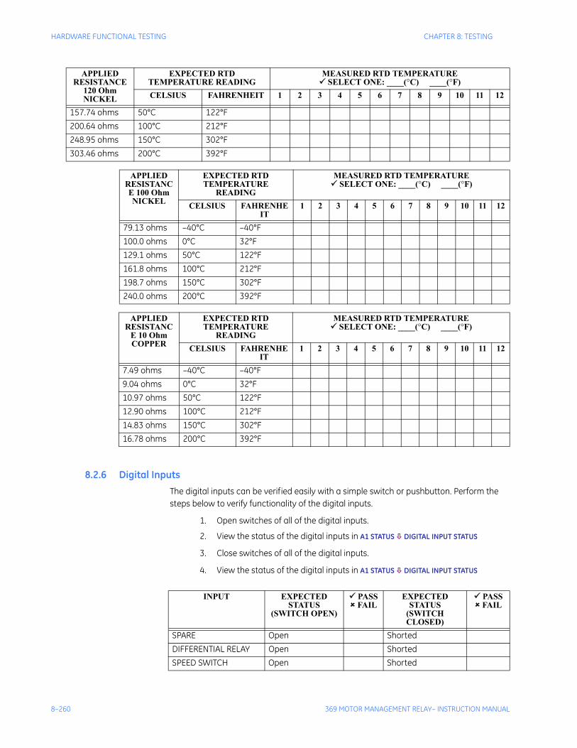
8–260 369 MOTOR MANAGEMENT RELAY– INSTRUCTION MANUAL
HARDWARE FUNCTIONAL TESTING CHAPTER 8: TESTING
8.2.6 Digital InputsThe digital inputs can be verified easily with a simple switch or pushbutton. Perform the steps below to verify functionality of the digital inputs.
1. Open switches of all of the digital inputs.
2. View the status of the digital inputs in A1 STATUS DIGITAL INPUT STATUS
3. Close switches of all of the digital inputs.
4. View the status of the digital inputs in A1 STATUS DIGITAL INPUT STATUS
157.74 ohms 50°C 122°F200.64 ohms 100°C 212°F248.95 ohms 150°C 302°F303.46 ohms 200°C 392°F
APPLIED RESISTANCE 100 Ohm NICKEL
EXPECTED RTD TEMPERATURE
READING
MEASURED RTD TEMPERATURE SELECT ONE: ____(°C) ____(°F)
CELSIUS FAHRENHEIT
1 2 3 4 5 6 7 8 9 10 11 12
79.13 ohms –40°C –40°F100.0 ohms 0°C 32°F129.1 ohms 50°C 122°F161.8 ohms 100°C 212°F198.7 ohms 150°C 302°F240.0 ohms 200°C 392°F
APPLIED RESISTANC
E 10 Ohm COPPER
EXPECTED RTD TEMPERATURE
READING
MEASURED RTD TEMPERATURE SELECT ONE: ____(°C) ____(°F)
CELSIUS FAHRENHEIT
1 2 3 4 5 6 7 8 9 10 11 12
7.49 ohms –40°C –40°F9.04 ohms 0°C 32°F10.97 ohms 50°C 122°F12.90 ohms 100°C 212°F14.83 ohms 150°C 302°F16.78 ohms 200°C 392°F
APPLIED RESISTANCE
120 Ohm NICKEL
EXPECTED RTD TEMPERATURE READING
MEASURED RTD TEMPERATURE SELECT ONE: ____(°C) ____(°F)
CELSIUS FAHRENHEIT 1 2 3 4 5 6 7 8 9 10 11 12
INPUT EXPECTED STATUS
(SWITCH OPEN)
PASS FAIL
EXPECTED STATUS
(SWITCH CLOSED)
PASS FAIL
SPARE Open ShortedDIFFERENTIAL RELAY Open ShortedSPEED SWITCH Open Shorted

CHAPTER 8: TESTING HARDWARE FUNCTIONAL TESTING
369 MOTOR MANAGEMENT RELAY– INSTRUCTION MANUAL 8–261
ACCESS SWITCH Open ShortedEMERGENCY RESTART Open ShortedEXTERNAL RESET Open Shorted
INPUT EXPECTED STATUS
(SWITCH OPEN)
PASS FAIL
EXPECTED STATUS
(SWITCH CLOSED)
PASS FAIL
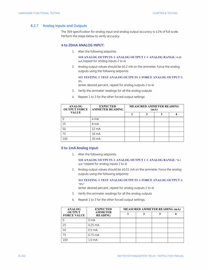
8–262 369 MOTOR MANAGEMENT RELAY– INSTRUCTION MANUAL
HARDWARE FUNCTIONAL TESTING CHAPTER 8: TESTING
8.2.7 Analog Inputs and OutputsThe 369 specification for analog input and analog output accuracy is ±1% of full scale. Perform the steps below to verify accuracy.
4 to 20mA ANALOG INPUT:
1. Alter the following setpoints:
S10 ANALOG OUTPUTS ANALOG OUTPUT 1 ANALOG RANGE: 4-20 mA (repeat for analog inputs 2 to 4)
2. Analog output values should be ±0.2 mA on the ammeter. Force the analog outputs using the following setpoints:
S11 TESTING TEST ANALOG OUTPUTS FORCE ANALOG OUTPUT 1: 0% (enter desired percent, repeat for analog outputs 2 to 4)
3. Verify the ammeter readings for all the analog outputs
4. Repeat 1 to 3 for the other forced output settings
0 to 1mA Analog Input:
1. Alter the following setpoints:
S10 ANALOG OUTPUTS ANALOG OUTPUT 1 ANALOG RANGE: “0-1 mA” (repeat for analog inputs 2 to 4)
2. Analog output values should be ±0.01 mA on the ammeter. Force the analog outputs using the following setpoints:
S11 TESTING TEST ANALOG OUTPUTS FORCE ANALOG OUTPUT 1: “0%”(enter desired percent, repeat for analog outputs 2 to 4)
3. Verify the ammeter readings for all the analog outputs
4. Repeat 1 to 3 for the other forced output settings.
ANALOG OUTPUT FORCE
VALUE
EXPECTED AMMETER READING
MEASURED AMMETER READING (mA)
1 2 3 40 4 mA25 8 mA50 12 mA75 16 mA100 20 mA
ANALOG OUTPUT
FORCE VALUE
EXPECTED AMMETER READING
MEASURED AMMETER READING (mA)1 2 3 4
0 0 mA25 0.25 mA50 0.5 mA75 0.75 mA100 1.0 mA
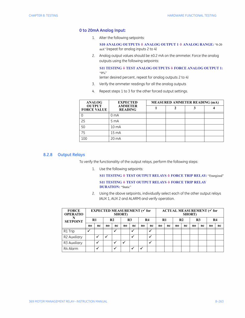
CHAPTER 8: TESTING HARDWARE FUNCTIONAL TESTING
369 MOTOR MANAGEMENT RELAY– INSTRUCTION MANUAL 8–263
0 to 20mA Analog Input:
1. Alter the following setpoints:
S10 ANALOG OUTPUTS ANALOG OUTPUT 1 ANALOG RANGE: “0-20 mA” (repeat for analog inputs 2 to 4)
2. Analog output values should be ±0.2 mA on the ammeter. Force the analog outputs using the following setpoints:
S11 TESTING TEST ANALOG OUTPUTS FORCE ANALOG OUTPUT 1: “0%”(enter desired percent, repeat for analog outputs 2 to 4)
3. Verify the ammeter readings for all the analog outputs
4. Repeat steps 1 to 3 for the other forced output settings.
8.2.8 Output RelaysTo verify the functionality of the output relays, perform the following steps:
1. Use the following setpoints:
S11 TESTING TEST OUTPUT RELAYS FORCE TRIP RELAY: “Energized”
S11 TESTING TEST OUTPUT RELAYS FORCE TRIP RELAY DURATION: “Static”
2. Using the above setpoints, individually select each of the other output relays (AUX 1, AUX 2 and ALARM) and verify operation.
ANALOG OUTPUT
FORCE VALUE
EXPECTED AMMETER READING
MEASURED AMMETER READING (mA)1 2 3 4
0 0 mA25 5 mA50 10 mA75 15 mA100 20 mA
FORCE OPERATIO
N SETPOINT
EXPECTED MEASUREMENT ( for SHORT)
ACTUAL MEASUREMENT ( for SHORT)
R1 R2 R3 R4 R1 R2 R3 R4no nc no nc no nc no nc no nc no nc no nc no nc
R1 TripR2 AuxiliaryR3 AuxiliaryR4 Alarm
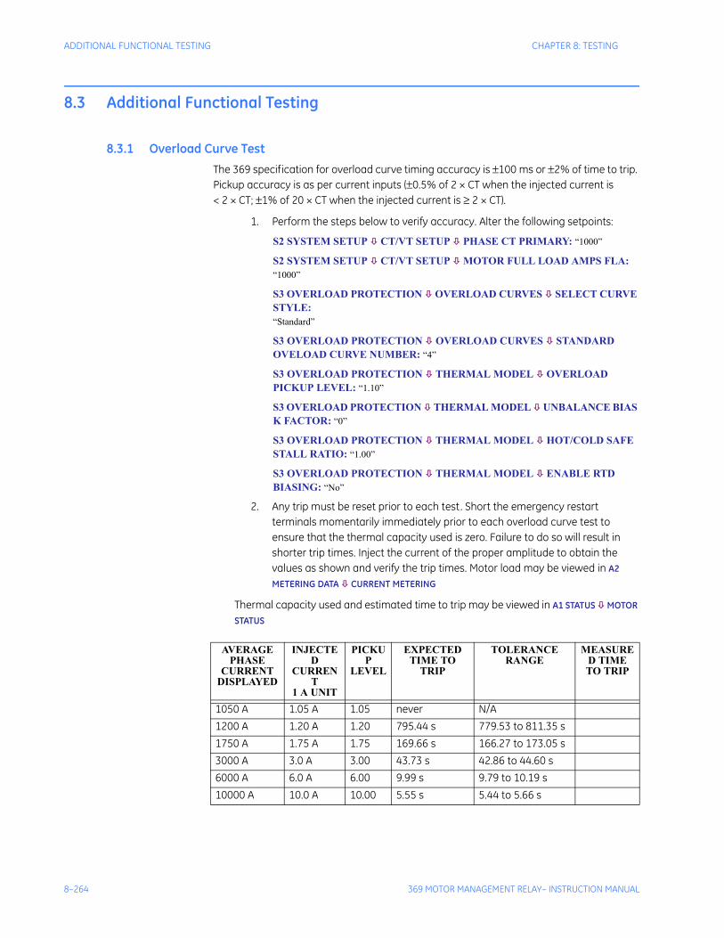
8–264 369 MOTOR MANAGEMENT RELAY– INSTRUCTION MANUAL
ADDITIONAL FUNCTIONAL TESTING CHAPTER 8: TESTING
8.3 Additional Functional Testing
8.3.1 Overload Curve TestThe 369 specification for overload curve timing accuracy is ±100 ms or ±2% of time to trip. Pickup accuracy is as per current inputs (±0.5% of 2 × CT when the injected current is < 2 × CT; ±1% of 20 × CT when the injected current is ≥ 2 × CT).
1. Perform the steps below to verify accuracy. Alter the following setpoints:
S2 SYSTEM SETUP CT/VT SETUP PHASE CT PRIMARY: “1000”
S2 SYSTEM SETUP CT/VT SETUP MOTOR FULL LOAD AMPS FLA: “1000”
S3 OVERLOAD PROTECTION OVERLOAD CURVES SELECT CURVE STYLE:“Standard”
S3 OVERLOAD PROTECTION OVERLOAD CURVES STANDARD OVELOAD CURVE NUMBER: “4”
S3 OVERLOAD PROTECTION THERMAL MODEL OVERLOAD PICKUP LEVEL: “1.10”
S3 OVERLOAD PROTECTION THERMAL MODEL UNBALANCE BIAS K FACTOR: “0”
S3 OVERLOAD PROTECTION THERMAL MODEL HOT/COLD SAFE STALL RATIO: “1.00”
S3 OVERLOAD PROTECTION THERMAL MODEL ENABLE RTD BIASING: “No”
2. Any trip must be reset prior to each test. Short the emergency restart terminals momentarily immediately prior to each overload curve test to ensure that the thermal capacity used is zero. Failure to do so will result in shorter trip times. Inject the current of the proper amplitude to obtain the values as shown and verify the trip times. Motor load may be viewed in A2
METERING DATA CURRENT METERING
Thermal capacity used and estimated time to trip may be viewed in A1 STATUS MOTOR
STATUS
AVERAGE PHASE
CURRENT DISPLAYED
INJECTED
CURRENT
1 A UNIT
PICKUP
LEVEL
EXPECTED TIME TO
TRIP
TOLERANCE RANGE
MEASURED TIME TO TRIP
1050 A 1.05 A 1.05 never N/A1200 A 1.20 A 1.20 795.44 s 779.53 to 811.35 s1750 A 1.75 A 1.75 169.66 s 166.27 to 173.05 s3000 A 3.0 A 3.00 43.73 s 42.86 to 44.60 s6000 A 6.0 A 6.00 9.99 s 9.79 to 10.19 s10000 A 10.0 A 10.00 5.55 s 5.44 to 5.66 s
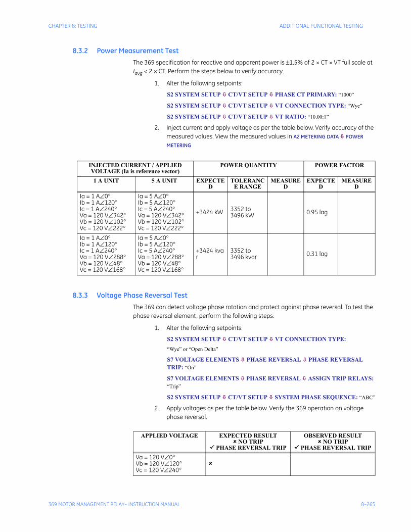
CHAPTER 8: TESTING ADDITIONAL FUNCTIONAL TESTING
369 MOTOR MANAGEMENT RELAY– INSTRUCTION MANUAL 8–265
8.3.2 Power Measurement TestThe 369 specification for reactive and apparent power is ±1.5% of 2 × CT × VT full scale at Iavg < 2 × CT. Perform the steps below to verify accuracy.
1. Alter the following setpoints:
S2 SYSTEM SETUP CT/VT SETUP PHASE CT PRIMARY: “1000”
S2 SYSTEM SETUP CT/VT SETUP VT CONNECTION TYPE: “Wye”
S2 SYSTEM SETUP CT/VT SETUP VT RATIO: “10.00:1”
2. Inject current and apply voltage as per the table below. Verify accuracy of the measured values. View the measured values in A2 METERING DATA POWER
METERING
8.3.3 Voltage Phase Reversal TestThe 369 can detect voltage phase rotation and protect against phase reversal. To test the phase reversal element, perform the following steps:
1. Alter the following setpoints:
S2 SYSTEM SETUP CT/VT SETUP VT CONNECTION TYPE: “Wye” or “Open Delta”
S7 VOLTAGE ELEMENTS PHASE REVERSAL PHASE REVERSAL TRIP: “On”
S7 VOLTAGE ELEMENTS PHASE REVERSAL ASSIGN TRIP RELAYS: “Trip”
S2 SYSTEM SETUP CT/VT SETUP SYSTEM PHASE SEQUENCE: “ABC”
2. Apply voltages as per the table below. Verify the 369 operation on voltage phase reversal.
INJECTED CURRENT / APPLIED VOLTAGE (Ia is reference vector)
POWER QUANTITY POWER FACTOR
1 A UNIT 5 A UNIT EXPECTED
TOLERANCE RANGE
MEASURED
EXPECTED
MEASURED
Ia = 1 A∠0°Ib = 1 A∠120°Ic = 1 A∠240°Va = 120 V∠342°Vb = 120 V∠102°Vc = 120 V∠222°
Ia = 5 A∠0°Ib = 5 A∠120°Ic = 5 A∠240°Va = 120 V∠342°Vb = 120 V∠102°Vc = 120 V∠222°
+3424 kW 3352 to 3496 kW 0.95 lag
Ia = 1 A∠0°Ib = 1 A∠120°Ic = 1 A∠240°Va = 120 V∠288°Vb = 120 V∠48°Vc = 120 V∠168°
Ia = 5 A∠0°Ib = 5 A∠120°Ic = 5 A∠240°Va = 120 V∠288°Vb = 120 V∠48°Vc = 120 V∠168°
+3424 kvar
3352 to 3496 kvar 0.31 lag
APPLIED VOLTAGE EXPECTED RESULT NO TRIP
PHASE REVERSAL TRIP
OBSERVED RESULT NO TRIP
PHASE REVERSAL TRIPVa = 120 V∠0°Vb = 120 V∠120°Vc = 120 V∠240°

8–266 369 MOTOR MANAGEMENT RELAY– INSTRUCTION MANUAL
ADDITIONAL FUNCTIONAL TESTING CHAPTER 8: TESTING
Va = 120 V∠0°Vb = 120 V∠240°Vc = 120 V∠120°
APPLIED VOLTAGE EXPECTED RESULT NO TRIP
PHASE REVERSAL TRIP
OBSERVED RESULT NO TRIP
PHASE REVERSAL TRIP
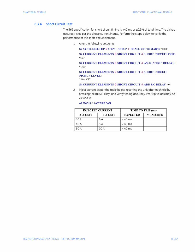
CHAPTER 8: TESTING ADDITIONAL FUNCTIONAL TESTING
369 MOTOR MANAGEMENT RELAY– INSTRUCTION MANUAL 8–267
8.3.4 Short Circuit TestThe 369 specification for short circuit timing is +40 ms or ±0.5% of total time. The pickup accuracy is as per the phase current inputs. Perform the steps below to verify the performance of the short circuit element.
1. Alter the following setpoints:
S2 SYSTEM SETUP CT/VT SETUP PHASE CT PRIMARY: “1000”
S4 CURRENT ELEMENTS SHORT CIRCUIT SHORT CIRCUIT TRIP: “On”
S4 CURRENT ELEMENTS SHORT CIRCUIT ASSIGN TRIP RELAYS: “Trip”
S4 CURRENT ELEMENTS SHORT CIRCUIT SHORT CIRCUIT PICKUP LEVEL: “5.0 x CT”
S4 CURRENT ELEMENTS SHORT CIRCUIT ADD S/C DELAY: “0”
2. Inject current as per the table below, resetting the unit after each trip by pressing the [RESET] key, and verify timing accuracy. Pre-trip values may be viewed in
A1 STATUS LAST TRIP DATA
INJECTED CURRENT TIME TO TRIP (ms)5 A UNIT 1 A UNIT EXPECTED MEASURED
30 A 6 A < 40 ms40 A 8 A < 40 ms50 A 10 A < 40 ms

8–268 369 MOTOR MANAGEMENT RELAY– INSTRUCTION MANUAL
ADDITIONAL FUNCTIONAL TESTING CHAPTER 8: TESTING
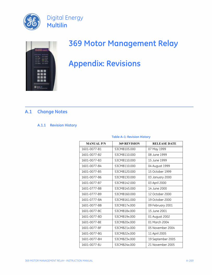
369 MOTOR MANAGEMENT RELAY– INSTRUCTION MANUAL A–269
369 Motor Management Relay
Appendix: Revisions
Digital EnergyMultilin
Revisions
A.1 Change Notes
A.1.1 Revision History
Table A–1: Revision History
MANUAL P/N 369 REVISION RELEASE DATE
1601-0077-B1 53CMB105.000 07 May 1999
1601-0077-B2 53CMB110.000 08 June 1999
1601-0077-B3 53CMB110.000 15 June 1999
1601-0077-B4 53CMB110.000 04 August 1999
1601-0077-B5 53CMB120.000 15 October 1999
1601-0077-B6 53CMB130.000 03 January 2000
1601-0077-B7 53CMB142.000 03 April 2000
1601-0777-B8 53CMB145.000 14 June 2000
1601-0777-B9 53CMB160.000 12 October 2000
1601-0777-BA 53CMB161.000 19 October 2000
1601-0077-BB 53CMB17x.000 09 February 2001
1601-0077-BC 53CMB18x.000 15 June 2001
1601-0077-BD 53CMB19x.000 01 August 2002
1601-0077-BE 53CMB20x.000 01 March 2004
1601-0077-BF 53CMB21x.000 05 November 2004
1601-0077-BG 53CMB22x.000 11 April 2005
1601-0077-BH 53CMB23x.000 19 September 2005
1601-0077-BJ 53CMB24x.000 21 November 2005
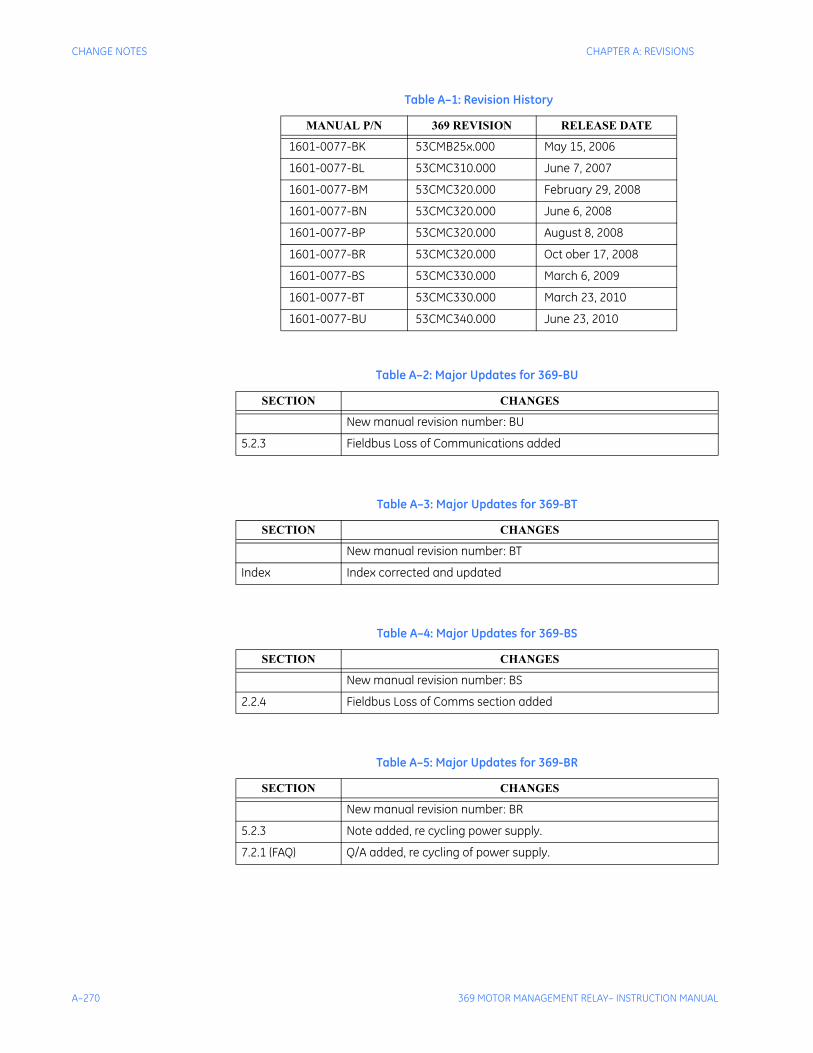
A–270 369 MOTOR MANAGEMENT RELAY– INSTRUCTION MANUAL
CHANGE NOTES CHAPTER A: REVISIONS
1601-0077-BK 53CMB25x.000 May 15, 2006
1601-0077-BL 53CMC310.000 June 7, 2007
1601-0077-BM 53CMC320.000 February 29, 2008
1601-0077-BN 53CMC320.000 June 6, 2008
1601-0077-BP 53CMC320.000 August 8, 2008
1601-0077-BR 53CMC320.000 Oct ober 17, 2008
1601-0077-BS 53CMC330.000 March 6, 2009
1601-0077-BT 53CMC330.000 March 23, 2010
1601-0077-BU 53CMC340.000 June 23, 2010
Table A–2: Major Updates for 369-BU
SECTION CHANGES
New manual revision number: BU
5.2.3 Fieldbus Loss of Communications added
Table A–3: Major Updates for 369-BT
SECTION CHANGES
New manual revision number: BT
Index Index corrected and updated
Table A–4: Major Updates for 369-BS
SECTION CHANGES
New manual revision number: BS
2.2.4 Fieldbus Loss of Comms section added
Table A–5: Major Updates for 369-BR
SECTION CHANGES
New manual revision number: BR
5.2.3 Note added, re cycling power supply.
7.2.1 (FAQ) Q/A added, re cycling of power supply.
Table A–1: Revision History
MANUAL P/N 369 REVISION RELEASE DATE
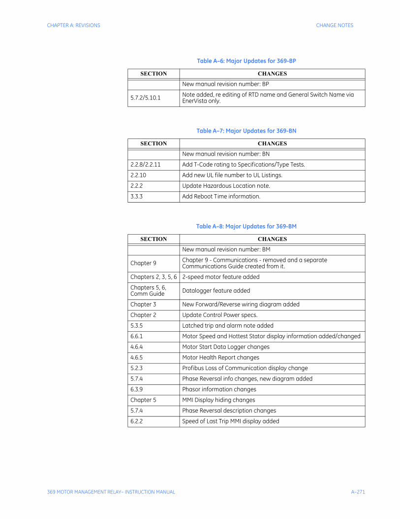
CHAPTER A: REVISIONS CHANGE NOTES
369 MOTOR MANAGEMENT RELAY– INSTRUCTION MANUAL A–271
Table A–6: Major Updates for 369-BP
SECTION CHANGES
New manual revision number: BP
5.7.2/5.10.1 Note added, re editing of RTD name and General Switch Name viaEnerVista only.
Table A–7: Major Updates for 369-BN
SECTION CHANGES
New manual revision number: BN
2.2.8/2.2.11 Add T-Code rating to Specifications/Type Tests.
2.2.10 Add new UL file number to UL Listings.
2.2.2 Update Hazardous Location note.
3.3.3 Add Reboot Time information.
Table A–8: Major Updates for 369-BM
SECTION CHANGES
New manual revision number: BM
Chapter 9 Chapter 9 - Communications - removed and a separate Communications Guide created from it.
Chapters 2, 3, 5, 6 2-speed motor feature added
Chapters 5, 6, Comm Guide Datalogger feature added
Chapter 3 New Forward/Reverse wiring diagram added
Chapter 2 Update Control Power specs.
5.3.5 Latched trip and alarm note added
6.6.1 Motor Speed and Hottest Stator display information added/changed
4.6.4 Motor Start Data Logger changes
4.6.5 Motor Health Report changes
5.2.3 Profibus Loss of Communication display change
5.7.4 Phase Reversal info changes, new diagram added
6.3.9 Phasor information changes
Chapter 5 MMI Display hiding changes
5.7.4 Phase Reversal description changes
6.2.2 Speed of Last Trip MMI display added
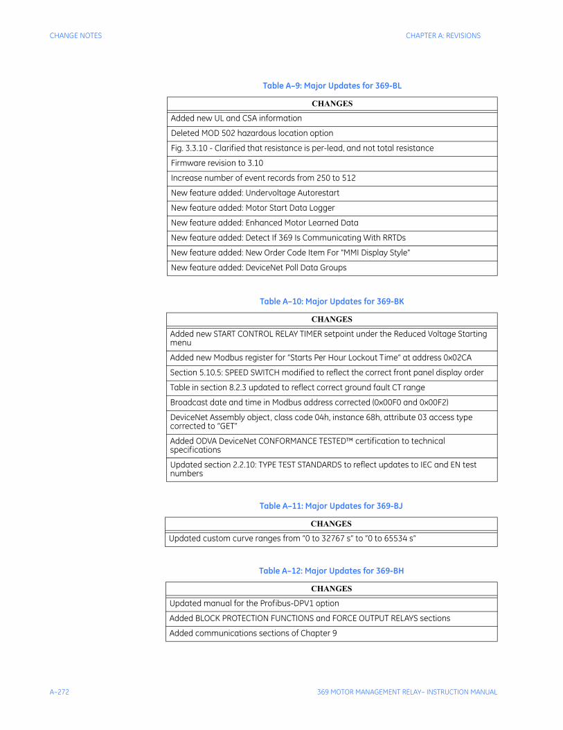
A–272 369 MOTOR MANAGEMENT RELAY– INSTRUCTION MANUAL
CHANGE NOTES CHAPTER A: REVISIONS
Table A–9: Major Updates for 369-BL
CHANGES
Added new UL and CSA information
Deleted MOD 502 hazardous location option
Fig. 3.3.10 - Clarified that resistance is per-lead, and not total resistance
Firmware revision to 3.10
Increase number of event records from 250 to 512
New feature added: Undervoltage Autorestart
New feature added: Motor Start Data Logger
New feature added: Enhanced Motor Learned Data
New feature added: Detect If 369 Is Communicating With RRTDs
New feature added: New Order Code Item For "MMI Display Style"
New feature added: DeviceNet Poll Data Groups
Table A–10: Major Updates for 369-BK
CHANGES
Added new START CONTROL RELAY TIMER setpoint under the Reduced Voltage Starting menu
Added new Modbus register for “Starts Per Hour Lockout Time” at address 0x02CA
Section 5.10.5: SPEED SWITCH modified to reflect the correct front panel display order
Table in section 8.2.3 updated to reflect correct ground fault CT range
Broadcast date and time in Modbus address corrected (0x00F0 and 0x00F2)
DeviceNet Assembly object, class code 04h, instance 68h, attribute 03 access type corrected to “GET”
Added ODVA DeviceNet CONFORMANCE TESTED™ certification to technical specifications
Updated section 2.2.10: TYPE TEST STANDARDS to reflect updates to IEC and EN test numbers
Table A–11: Major Updates for 369-BJ
CHANGES
Updated custom curve ranges from “0 to 32767 s” to “0 to 65534 s”
Table A–12: Major Updates for 369-BH
CHANGES
Updated manual for the Profibus-DPV1 option
Added BLOCK PROTECTION FUNCTIONS and FORCE OUTPUT RELAYS sections
Added communications sections of Chapter 9
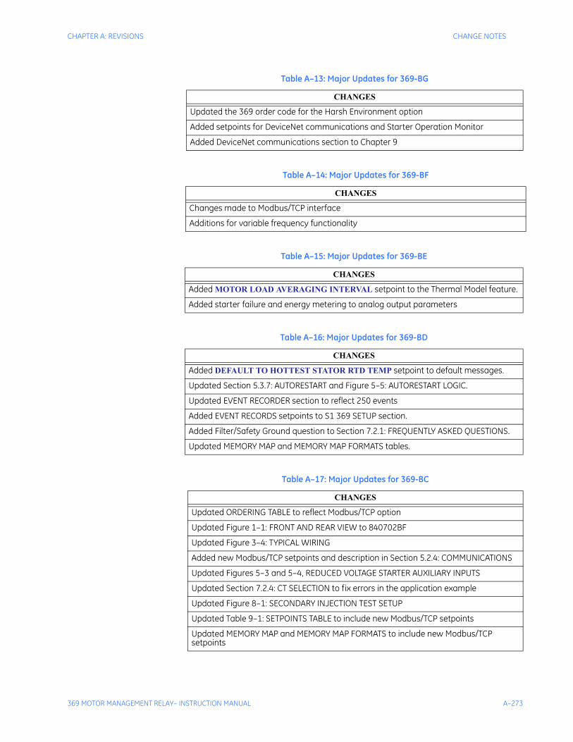
CHAPTER A: REVISIONS CHANGE NOTES
369 MOTOR MANAGEMENT RELAY– INSTRUCTION MANUAL A–273
Table A–13: Major Updates for 369-BG
CHANGES
Updated the 369 order code for the Harsh Environment option
Added setpoints for DeviceNet communications and Starter Operation Monitor
Added DeviceNet communications section to Chapter 9
Table A–14: Major Updates for 369-BF
CHANGES
Changes made to Modbus/TCP interface
Additions for variable frequency functionality
Table A–15: Major Updates for 369-BE
CHANGES
Added MOTOR LOAD AVERAGING INTERVAL setpoint to the Thermal Model feature.
Added starter failure and energy metering to analog output parameters
Table A–16: Major Updates for 369-BD
CHANGES
Added DEFAULT TO HOTTEST STATOR RTD TEMP setpoint to default messages.
Updated Section 5.3.7: AUTORESTART and Figure 5–5: AUTORESTART LOGIC.
Updated EVENT RECORDER section to reflect 250 events
Added EVENT RECORDS setpoints to S1 369 SETUP section.
Added Filter/Safety Ground question to Section 7.2.1: FREQUENTLY ASKED QUESTIONS.
Updated MEMORY MAP and MEMORY MAP FORMATS tables.
Table A–17: Major Updates for 369-BC
CHANGES
Updated ORDERING TABLE to reflect Modbus/TCP option
Updated Figure 1–1: FRONT AND REAR VIEW to 840702BF
Updated Figure 3–4: TYPICAL WIRING
Added new Modbus/TCP setpoints and description in Section 5.2.4: COMMUNICATIONS
Updated Figures 5–3 and 5–4, REDUCED VOLTAGE STARTER AUXILIARY INPUTS
Updated Section 7.2.4: CT SELECTION to fix errors in the application example
Updated Figure 8–1: SECONDARY INJECTION TEST SETUP
Updated Table 9–1: SETPOINTS TABLE to include new Modbus/TCP setpoints
Updated MEMORY MAP and MEMORY MAP FORMATS to include new Modbus/TCP setpoints
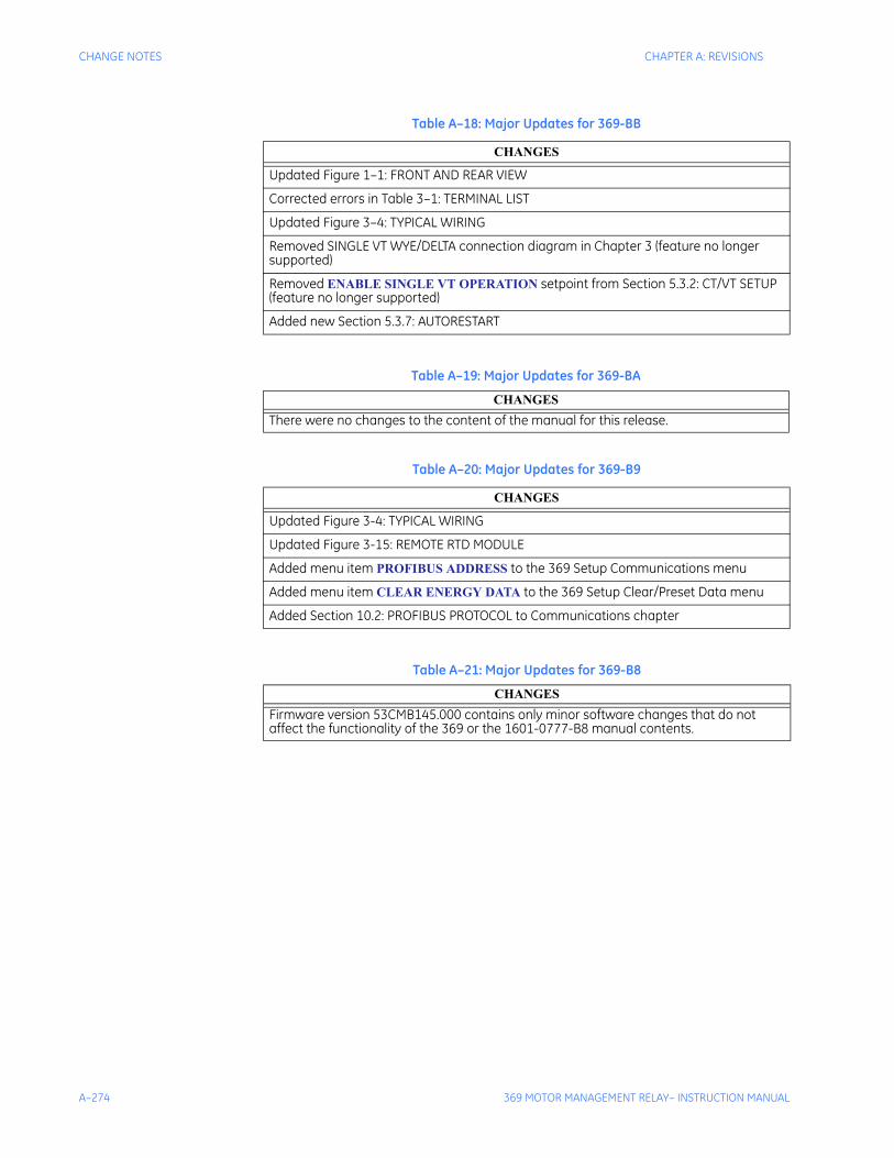
A–274 369 MOTOR MANAGEMENT RELAY– INSTRUCTION MANUAL
CHANGE NOTES CHAPTER A: REVISIONS
Table A–18: Major Updates for 369-BB
CHANGES
Updated Figure 1–1: FRONT AND REAR VIEW
Corrected errors in Table 3–1: TERMINAL LIST
Updated Figure 3–4: TYPICAL WIRING
Removed SINGLE VT WYE/DELTA connection diagram in Chapter 3 (feature no longer supported)
Removed ENABLE SINGLE VT OPERATION setpoint from Section 5.3.2: CT/VT SETUP (feature no longer supported)
Added new Section 5.3.7: AUTORESTART
Table A–19: Major Updates for 369-BA
CHANGESThere were no changes to the content of the manual for this release.
Table A–20: Major Updates for 369-B9
CHANGES
Updated Figure 3-4: TYPICAL WIRING
Updated Figure 3-15: REMOTE RTD MODULE
Added menu item PROFIBUS ADDRESS to the 369 Setup Communications menu
Added menu item CLEAR ENERGY DATA to the 369 Setup Clear/Preset Data menu
Added Section 10.2: PROFIBUS PROTOCOL to Communications chapter
Table A–21: Major Updates for 369-B8
CHANGESFirmware version 53CMB145.000 contains only minor software changes that do not affect the functionality of the 369 or the 1601-0777-B8 manual contents.
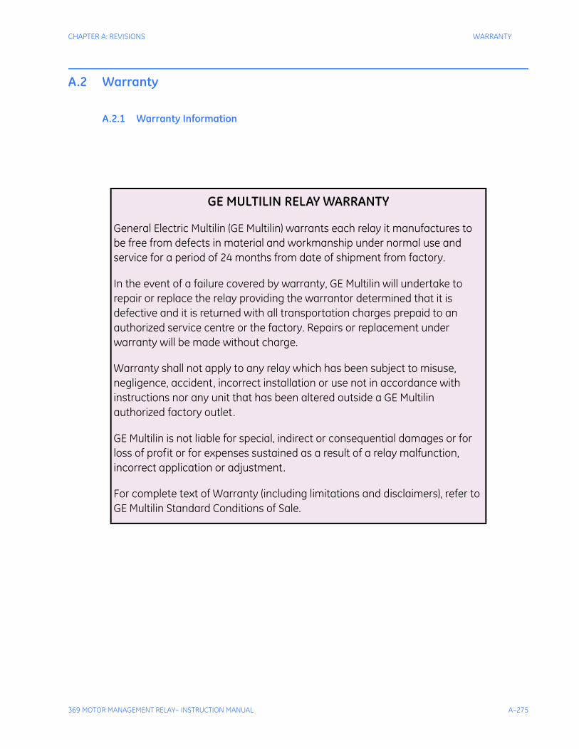
CHAPTER A: REVISIONS WARRANTY
369 MOTOR MANAGEMENT RELAY– INSTRUCTION MANUAL A–275
A.2 Warranty
A.2.1 Warranty Information
GE MULTILIN RELAY WARRANTY
General Electric Multilin (GE Multilin) warrants each relay it manufactures to be free from defects in material and workmanship under normal use and service for a period of 24 months from date of shipment from factory.
In the event of a failure covered by warranty, GE Multilin will undertake to repair or replace the relay providing the warrantor determined that it is defective and it is returned with all transportation charges prepaid to an authorized service centre or the factory. Repairs or replacement under warranty will be made without charge.
Warranty shall not apply to any relay which has been subject to misuse, negligence, accident, incorrect installation or use not in accordance with instructions nor any unit that has been altered outside a GE Multilin authorized factory outlet.
GE Multilin is not liable for special, indirect or consequential damages or for loss of profit or for expenses sustained as a result of a relay malfunction, incorrect application or adjustment.
For complete text of Warranty (including limitations and disclaimers), refer to GE Multilin Standard Conditions of Sale.

A–276 369 MOTOR MANAGEMENT RELAY– INSTRUCTION MANUAL
WARRANTY CHAPTER A: REVISIONS
369 MOTOR MANAGEMENT RELAY– INSTRUCTION MANUAL INDEX–1
369 Motor Management Relay
Index
Digital EnergyMultilin
Index
Numerics2 PHASE CT CONFIGURATION ......................................................................... 7-248269-369 CONVERSION TERMINAL LIST ..............................................................3-31369
pc interface .......................................................................................................4-605A
ground CT installation ........................................................................................3-55input ............................................................................................................... 8-258
86 LOCKOUT SWITCH ...................................................................................... 7-229
AA1 STATUS ....................................................................................................... 6-202A2 METERING DATA ......................................................................................... 6-207A3 LEARNED DATA........................................................................................... 6-213A4 STATISTICAL DATA ..................................................................................... 6-216A5 EVENT RECORD .......................................................................................... 6-219A6 RELAY INFORMATION ................................................................................. 6-220ACCELERATION TRIP ............................................................................ 5-161, 7-237ACCESS SECURITY .......................................................................................... 5-111ACCESS SWITCH ............................................................................................. 5-187ACCESSORIES .................................................................................................... 1-3ACTUAL VALUES .............................................................................................. 6-199
main menu ...................................................................................................... 6-199overview ......................................................................................................... 6-199page 6 menu ................................................................................................... 6-220
ADDITIONAL FEATURES.....................................................................................2-12ADDITIONAL FUNCTIONAL TING ...................................................................... 8-264ALARM RELAY
setpoints ......................................................................................................... 5-130ALARM STATUS ................................................................................................ 6-203ANALOG
inputs and outputs ........................................................................................... 8-262outputs ......................................................................................... 3-42, 3-43, 5-190outputs (Option M) .............................................................................................2-15
APPROVALS / CERTIFICATION ...........................................................................2-24AUTO TRANSFORMER STARTER WIRING ........................................................ 7-253AUTORESTART .......................................................................... 5-134, 5-136, 5-137AUX 1 RELAY
INDEX–2 369 MOTOR MANAGEMENT RELAY– INSTRUCTION MANUAL
INDEX
see AUXILIARY RELAYSAUX 2 RELAY
see AUXILIARY RELAYSAUXILIARY RELAYS
setpoints ......................................................................................................... 5-130
BBACK PORTS (3) ................................................................................................ 2-17BACKSPIN
detection ......................................................................................................... 5-163voltage inputs ................................................................................................... 3-41
BEARING RTDS ................................................................................................ 7-238BSD INPUTS (OPTION B) .................................................................................... 2-15
CCLEAR/PRESET DATA ...................................................................................... 5-120COMMUNICATIONS ............................................................................................ 2-17
control ............................................................................................................ 5-132Modbus/TCP ................................................................................................... 5-113RS232 ..................................................................................................... 4-63, 4-65RS485 ..................................................................................................... 4-63, 4-65
CONTROLfunctions ......................................................................................................... 5-131power ...................................................................................................... 3-38, 3-44
COOL TIME CONSTANTS ................................................................................. 7-240CORE BALANCE CONNECTION ........................................................................ 7-224CT
burden ............................................................................................................ 7-231circuit ............................................................................................................. 7-232ground CT primary .......................................................................................... 5-122phase CT primary ............................................................................................ 5-122secondary resistance....................................................................................... 7-231selection ......................................................................................................... 7-231setpoints ......................................................................................................... 5-122size and saturation .......................................................................................... 7-230withstand ........................................................................................................ 7-230
CT AND VTpolarity ........................................................................................................... 7-227
CT/VT SETUP ................................................................................................... 5-122CURRENT
metering ......................................................................................................... 6-207unbalance ....................................................................................................... 5-158
CURRENT DEMAND ............................................................................... 5-126, 5-127CURRENT TRANSFORMER
see CTCUSTOM OVERLOAD CURVE ........................................................................... 5-148
DDATE ................................................................................................................ 5-115DEFAULT MESSAGES
cycle time ....................................................................................................... 5-111setpoints ......................................................................................................... 5-119timeout ........................................................................................................... 5-111
DEMANDcalculation ...................................................................................................... 5-127metering ......................................................................................................... 6-210setpoints .............................................................................................. 5-126, 5-127
DEVICENET
INDEX
369 MOTOR MANAGEMENT RELAY– INSTRUCTION MANUAL INDEX–3
settings ........................................................................................................... 5-113specifications ....................................................................................................2-17
DIAGNOSTIC MESSAGES ................................................................................. 6-203DIELECTRIC STRENGTH ....................................................................................2-24DIFFERENTIAL SWITCH ................................................................................... 5-187Digital ............................................................................................................... 8-260DIGITAL COUNTER ........................................................................................... 5-185DIGITAL INPUT ................................................................................................. 7-229
status.............................................................................................................. 6-204DIGITAL INPUT FUNCTION
digital counter ................................................................................................. 5-185general switch ................................................................................................. 5-184waveform capture ............................................................................................ 5-185
DISPLAY .............................................................................................................4-57preferences ..................................................................................................... 5-111
DO’S AND DON’TS ............................................................................................ 7-227DUST/MOISTURE ....................................................................................... 2-22, 2-25
EELECTRICAL INSTALLATION ..............................................................................3-37EMERGENCY RESTART.................................................................................... 5-187EMI .....................................................................................................................2-25ENABLE
start inhibit ...................................................................................................... 7-237ENERVISTA VIEWPOINT WITH THE 369 ........................................................... 4-102ENVIRONMENATAL SPECIFICATIONS ................................................................2-22ENVIRONMENT ...................................................................................................2-25ETHERNET
specifications ....................................................................................................2-17
FFACEPLATE
interface............................................................................................................4-57FACTORY DATA ............................................................................................... 5-121FAQ .................................................................................................................. 7-223FAST TRANSIENTS.............................................................................................2-25FIBER OPTIC PORT (OPTION F) .........................................................................2-17FIRMWARE
history................................................................................................................ 1-3upgrading via EnerVista 369 setup software .......................................................4-84version ............................................................................................................ 6-220
FLA ................................................................................................................... 5-123FLASH MESSAGES
duration .......................................................................................................... 5-111FORCE OUTPUT RELAYS
settings ........................................................................................................... 5-139FREQUENCY .................................................................................................... 5-124FREQUENTLY ASKED QUESTIONS .................................................................. 7-223FRONT PORT......................................................................................................2-17
communicating ................................................................................................ 7-223FULL LOAD AMPS ............................................................................................. 5-123
GGATEWAY ADDRESS ........................................................................................ 5-113GENERAL SWITCH ........................................................................................... 5-184GROUND
(1A/5A) ACCURACY TEST .............................................................................. 8-258accuracy test ................................................................................................... 8-258
INDEX–4 369 MOTOR MANAGEMENT RELAY– INSTRUCTION MANUAL
INDEX
bus ................................................................................................................. 7-227CT ....................................................................................................... 5-123, 7-234current input...................................................................................................... 3-39fault ..................................................................................................... 5-159, 7-237fault detection
ungrounded systems............................................................................... 7-250filter ................................................................................................................ 7-227safety ............................................................................................................. 7-227
GUIDEFORM SPECIFICATIONS ............................................................................2-9
HHARDWARE FUNCTIONAL TESTING ................................................................ 8-257HGF GROUND CT INSTALLATION
3” and 5” window ............................................................................................... 3-568” window ......................................................................................................... 3-56
HOT/COLD CURVE RATIO ..................................................................... 5-151, 7-235HOT/COLD SAFE STALL RATIO ........................................................................ 5-143HUMIDITY ........................................................................................................... 2-25
IIED SETUP ......................................................................................................... 4-60IMPULSE TEST ................................................................................................... 2-24INPUTS ............................................................................................................... 2-13INSTALLATION ................................................................................................... 3-27
electrical ........................................................................................................... 3-37mechanical ....................................................................................................... 3-27upgrade ............................................................................................................ 4-60
INSULATION RESISTANCE ................................................................................. 2-25INTRODUCTION AND ORDERING .........................................................................1-1IP ADDRESS ..................................................................................................... 5-113
KKEYPAD ............................................................................................................. 4-58
LLAG POWER FACTOR ...................................................................................... 5-179LAST TRIP DATA .............................................................................................. 6-202LEAD POWER FACTOR .................................................................................... 5-178LEARNED START CAPACITY ............................................................................ 7-247LOCAL / REMOTE RTD OPERATION ................................................................. 5-167LOCAL RTD ...................................................................................................... 6-209
maximums ...................................................................................................... 6-214protection........................................................................................................ 5-165
LONG-TERM STORAGE ...................................................................................... 2-24
MMECHANICAL INSTALLATION ............................................................................. 3-27MECHANICAL JAM ................................................................................. 5-156, 7-236MESSAGE SCRATCHPAD ................................................................................. 5-118METERED QUANTITIES ...................................................................................... 2-10METERING ......................................................................................................... 2-16MODBUS
serial communications control .......................................................................... 5-132setpoints .............................................................................................. 5-112, 5-114
INDEX
369 MOTOR MANAGEMENT RELAY– INSTRUCTION MANUAL INDEX–5
MODBUS/TCP COMMUNICATIONS ................................................................... 5-113MODEL INFORMATION ..................................................................................... 6-220MODIFY OPTIONS ............................................................................................ 5-121MONITORING SETUP........................................................................................ 5-125MOTOR
cooling ............................................................................................................ 5-151data ................................................................................................................ 6-213FLA................................................................................................................. 5-123FLC ................................................................................................................ 7-234rated voltage ................................................................................................... 5-122statistics ......................................................................................................... 6-217status................................................................................................... 6-202, 6-204status detection ............................................................................................... 7-239thermal limits .................................................................................................. 7-234
MOTOR FLA ...................................................................................................... 5-123MPM-369
conversion terminal list ......................................................................................3-35MTM-369
conversion terminal list ......................................................................................3-34
NNEGATIVE REACTIVE POWER ......................................................................... 5-180NOMINAL FREQUENCY .................................................................................... 5-124
OOPEN RTD ALARM ............................................................................................ 5-169OPERATION...................................................................................................... 5-131OPTIONS, MODIFYING ..................................................................................... 5-121ORDERING .......................................................................................................... 1-2OUTPUT RELAYS ........................................................................... 2-15, 3-44, 8-263
forcing ............................................................................................................ 5-139setpoints .............................................................................................. 5-129, 5-130
OUTPUTS ...........................................................................................................2-15OVERFREQUENCY ........................................................................................... 5-176OVERLOAD
alarm .............................................................................................................. 5-154curve .............................................................................................................. 7-236curve test ........................................................................................................ 8-264pickup ............................................................................................................. 7-235
OVERLOAD CURVEScustom ............................................................................................................ 5-148setpoints ................................................................................... 5-144, 5-145, 5-196standard ................................................................................... 5-145, 5-146, 5-147
OVERLOAD/STALL/THERMAL MODEL ................................................................2-18OVERVOLTAGE ................................................................................................ 5-172
PPARITY ............................................................................................................. 5-112PASSWORDS
comm password .............................................................................................. 5-111PC PROGRAM
software history .................................................................................................. 1-4PC SOFTWARE
obtaining ......................................................................................................... 7-223PHASE
CT ....................................................................................................... 5-122, 7-234CT installation ...................................................................................................3-54current (CT) inputs ............................................................................................3-38
INDEX–6 369 MOTOR MANAGEMENT RELAY– INSTRUCTION MANUAL
INDEX
current accuracy test ....................................................................................... 8-257line voltage input, VT (Option M) ........................................................................ 2-14reversal .......................................................................................................... 5-173voltage (VT/PT) inputs ....................................................................................... 3-40VT .................................................................................................................. 5-123
PHASE SEQUENCY .......................................................................................... 5-124PHASORS ......................................................................................................... 6-211POLARITY
CT and VT ...................................................................................................... 7-227POSITIVE REACTIVE POWER ........................................................................... 5-179POWER
measurement test ............................................................................................ 8-265metering ......................................................................................................... 6-208metering (option m) ........................................................................................... 2-16
POWER DEMAND ............................................................................................. 5-127PRODUCTION TESTS ......................................................................................... 2-25PROFIBUS
setpoints ......................................................................................................... 5-114PROFIBUS ADDRESS ....................................................................................... 5-113PROFIBUS PORT (OPTION P) ............................................................................. 2-17PROGRAMMING EXAMPLE ............................................................................... 7-233PROTECTION ELEMENTS................................................................................... 2-18
RREAL TIME CLOCK ........................................................................................... 6-206
setpoints ......................................................................................................... 5-115REDUCED RTD LEAD NUMBER ........................................................................ 7-251REDUCED VOLTAGE START ................................................................. 5-132, 5-134RELAY LABEL DEFINITION ...................................................................................1-8REMOTE RESET ............................................................................................... 5-189REMOTE RTD ................................................................................................... 6-209
address........................................................................................................... 5-112maximums ...................................................................................................... 6-215module electrical installation .............................................................................. 3-53module mechanical installation .......................................................................... 3-51protection........................................................................................................ 5-166
RESET .............................................................................................................. 5-130RESIDUAL GROUND FAULT CONNECTION ...................................................... 7-224REVERSE POWER ............................................................................................ 5-183REVISION HISTORY ........................................................................................ A-269RFI ..................................................................................................................... 2-25ROLLING DEMAND WINDOW ............................................................................ 5-127RRTD ADDRESS ............................................................................................... 5-112RS232
communicating ................................................................................................ 7-223program port ..................................................................................................... 4-58setpoints ......................................................................................................... 5-112
RS232 COMMUNICATIONSconfiguring with EnerVista 369 Setup ................................................................. 4-63configuring with EnerVista 369 setup ................................................................. 4-65
RS4854 wire ............................................................................................................. 7-223cable .............................................................................................................. 7-228communication difficulties ................................................................................ 7-223communications ................................................................................................ 3-45communications port ....................................................................................... 7-228converter ........................................................................................................ 7-228distances ........................................................................................................ 7-228full duplex ....................................................................................................... 7-223interfacing master device ................................................................................. 7-228repeater .......................................................................................................... 7-228setpoints ......................................................................................................... 5-112
INDEX
369 MOTOR MANAGEMENT RELAY– INSTRUCTION MANUAL INDEX–7
RS485 COMMUNICATIONSconfiguring with EnerVista 369 setup ......................................................... 4-63, 4-65
RTD ......................................................................................................... 3-42, 7-2272 wire lead compensation ................................................................................ 7-253accuracy test ................................................................................................... 8-259bias .......................................................................................... 5-143, 5-152, 5-153bias maximum ................................................................................................. 7-236bias mid point .................................................................................................. 7-236bias minimum .................................................................................................. 7-236circuitry ........................................................................................................... 7-251grounding ........................................................................................................ 7-229inputs................................................................................................................3-42inputs (Option r) ................................................................................................2-15stator .............................................................................................................. 7-237
RUNNING COOL TIME ...................................................................................... 7-235
SS10 ANALOG OUTPUTS .................................................................................... 5-190S11 369 TESTING ............................................................................................. 5-192S2 SYSTEM SETUP .......................................................................................... 5-122S3 OVERLOAD PROTECTION ........................................................................... 5-141S4 CURRENT ELEMENTS ................................................................................. 5-155S5 MOTOR START / INHIBITS ........................................................................... 5-161S6 RTD TEMPERATURE ................................................................................... 5-165S7 VOLTAGE ELEMENTS .................................................................................. 5-171S8 POWER ELEMENTS ..................................................................................... 5-177S9 DIGITAL INPUTS .......................................................................................... 5-184SECONDARY INJECTION TEST SETUP ............................................................ 8-256SECURITY ........................................................................................................ 5-111SELF-TEST MODE ............................................................................................ 5-129SELF-TEST RELAY ........................................................................................... 5-129SERIAL COMMUNICATION CONTROL ............................................................... 5-132SETPOINTS ...................................................................................................... 5-107
access ............................................................................................................ 5-111entering with EnerVista 369 Setup software ........................................................4-69entry .................................................................................................................4-59loading from a file ..............................................................................................4-83main menu ...................................................................................................... 5-107page 1 menu ................................................................................................... 5-111saving to a file ...................................................................................................4-84
SHORT CIRCUIT ............................................................................................... 5-155test ................................................................................................................. 8-267trip .................................................................................................................. 7-236
SHORT/LOW TEMP RTD ALARM ....................................................................... 5-169SOFTWARE
entering setpoints ..............................................................................................4-69installation ........................................................................................................4-60loading setpoints ...............................................................................................4-83saving setpoints ................................................................................................4-84serial communications .............................................................................. 4-63, 4-65
SPARE SWITCH ................................................................................................ 5-186SPEED SWITCH ................................................................................................ 5-188START INHIBIT ........................................................................... 5-162, 7-241, 7-246
enabled ........................................................................................................... 7-247starter
status switch ................................................................................................... 5-133STARTER FAILURE........................................................................................... 5-126STARTS/HOUR ................................................................................................. 7-237STATOR RTDS .................................................................................................. 7-237STOPPED COOL TIME ...................................................................................... 7-236STOPPED COOL TIME CONSTANT ................................................................... 7-241SUBNET MASK ................................................................................................. 5-113
INDEX–8 369 MOTOR MANAGEMENT RELAY– INSTRUCTION MANUAL
INDEX
SYSTEM ........................................................................................................... 5-124SYSTEM FREQUENCY ...................................................................................... 5-124
TTECHNICAL SPECIFICATIONS............................................................................ 2-13TEMPERATURE .................................................................................................. 2-25TEMPERATURE DISPLAY ................................................................................. 5-111TERMINAL
identification ..................................................................................................... 3-29layout ............................................................................................................... 3-36list .................................................................................................................... 3-29
TESTburn in .............................................................................................................. 2-25calibration and functionality ............................................................................... 2-25dielectric strength .............................................................................................. 2-25ground accuracy .............................................................................................. 8-258hardware functional ......................................................................................... 8-257input accuracy ................................................................................................. 8-257overload curve ................................................................................................ 8-264phase current accuracy ................................................................................... 8-257power measurement ........................................................................................ 8-265production ......................................................................................................... 2-25RTD accuracy ................................................................................................. 8-259secondary injection ......................................................................................... 8-256setup .............................................................................................................. 8-255short circuit ..................................................................................................... 8-267type test standards ............................................................................................ 2-24unbalance ....................................................................................................... 8-265voltage
metering ............................................................................................... 6-207phase reversal ....................................................................................... 8-265
TESTINGanalog outputs ................................................................................................ 5-193output relays ................................................................................................... 5-192setpoints ......................................................................................................... 5-192
THERMALcapacity calculation ......................................................................................... 7-244capacity used .................................................................................................. 7-244limit ................................................................................................................ 7-241limit curves ..................................................................................................... 7-246
THERMAL CAPACITY USED.............................................................................. 5-143THERMAL MODEL
cooling ............................................................................................................ 5-152description ...................................................................................................... 5-142limit curves ..................................................................................................... 5-142setpoints ......................................................................................................... 5-142
TIME ................................................................................................................. 5-115TIME BETWEEN STARTS .................................................................................. 7-237TRENDING.......................................................................................................... 4-87TRIP COUNTER .......................................................................... 5-125, 6-209, 6-216TRIP RELAY ....................................................................................................... 3-45
setpoints ......................................................................................................... 5-130TWO PHASE WIRING ........................................................................................ 7-248TWO WIRE RTD LEAD COMPENSATION ........................................................... 7-253TYPE TEST STANDARDS.................................................................................... 2-24
UUNBALANCE
alarm and trip .................................................................................................. 7-237bias ................................................................................................................ 5-149
INDEX
369 MOTOR MANAGEMENT RELAY– INSTRUCTION MANUAL INDEX–9
bias k factor .................................................................................................... 7-235bias of thermal capacity ................................................................................... 7-235setpoints ......................................................................................................... 5-142test ................................................................................................................. 8-265
UNDERCURRENT .................................................................................. 5-157, 7-237UNDERFREQUENCY ......................................................................................... 5-175UNDERPOWER ................................................................................................. 5-182UNDERVOLTAGE .............................................................................................. 5-171UPGRADING FIRMWARE ....................................................................................4-84
VVIBRATION .........................................................................................................2-23VOLTAGE
input accuracy test .......................................................................................... 8-257metering ......................................................................................................... 6-207phase reversal test .......................................................................................... 8-265
VOLTAGE TRANSFORMERsee VT
VTconnection type ............................................................................................... 5-123ratio ................................................................................................................ 5-123
VT RATIO............................................................................................... 5-122, 5-123VT SETTINGS ................................................................................................... 7-234
WWARRANTY ..................................................................................................... A-275WAVEFORM CAPTURE ................................................................. 2-16, 5-116, 5-185
setpoints .............................................................................................. 5-116, 5-118WIRING DIAGRAM ..............................................................................................3-37
ZZERO SEQUENCE
ground CT placement ........................................................................................3-40

INDEX–10 369 MOTOR MANAGEMENT RELAY– INSTRUCTION MANUAL
INDEX