FUSION AGRICULTURAL SLURRY TANKS - Home | … Engineering Co., Inc. Cathodic Protection Services...
20
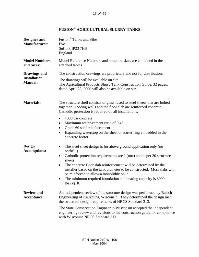
17-WI-79 FUSION ® AGRICULTURAL SLURRY TANKS Designer and Manufacturer: Fusion ® Tanks and Silos Eye Suffolk IP23 7HS England Model Numbers and Sizes: Model Reference Numbers and structure sizes are contained in the attached tables. Drawings and Installation Manual: The construction drawings are proprietary and not for distribution. The drawings will be available on site. The Agricultural Products Slurry Tank Construction Guide , 32 pages, dated April 28, 2000 will also be available on site. Materials: The structure shell consists of glass fused to steel sheets that are bolted together. Footing walls and the floor slab are reinforced concrete. Cathodic protection is required on all installations. • 4000 psi concrete • Maximum water-cement ratio of 0.46 • Grade 60 steel reinforcement • Expanding waterstop on the sheet or starter ring embedded in the concrete footer. Design Assumptions: • The steel sheet design is for above ground application only (no backfill). • Cathodic protection requirements are 1 (one) anode per 20 structure sheets. • The concrete floor slab reinforcement will be determined by the installer based on the tank diameter to be constructed. Most slabs will be reinforced to allow a monolithic pour. • The minimum required foundation soil bearing capacity is 3000 lbs./sq. ft. Review and Acceptance: An independent review of the structure design was performed by Baisch Engineering of Kaukauna, Wisconsin. They determined the design met the structural design requirements of NRCS Standard 313. The State Conservation Engineer in Wisconsin accepted the independent engineering review and revisions to the construction guide for compliance with Wisconsin NRCS Standard 313. EFH Notice 210-WI-106 May 2004
-
Upload
duongthuan -
Category
Documents
-
view
216 -
download
2
Transcript of FUSION AGRICULTURAL SLURRY TANKS - Home | … Engineering Co., Inc. Cathodic Protection Services...
17-WI-79
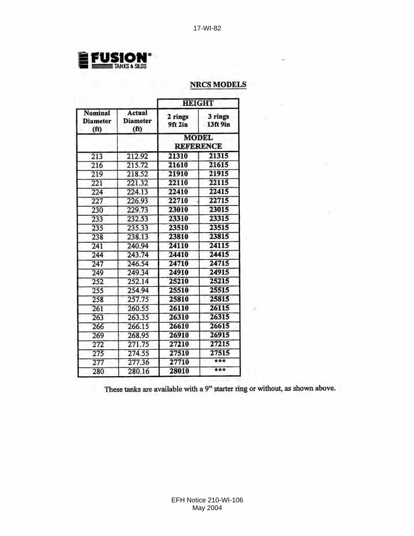
FUSION® AGRICULTURAL SLURRY TANKS Designer and Manufacturer:
Fusion® Tanks and Silos Eye Suffolk IP23 7HS England
Model Numbers and Sizes:
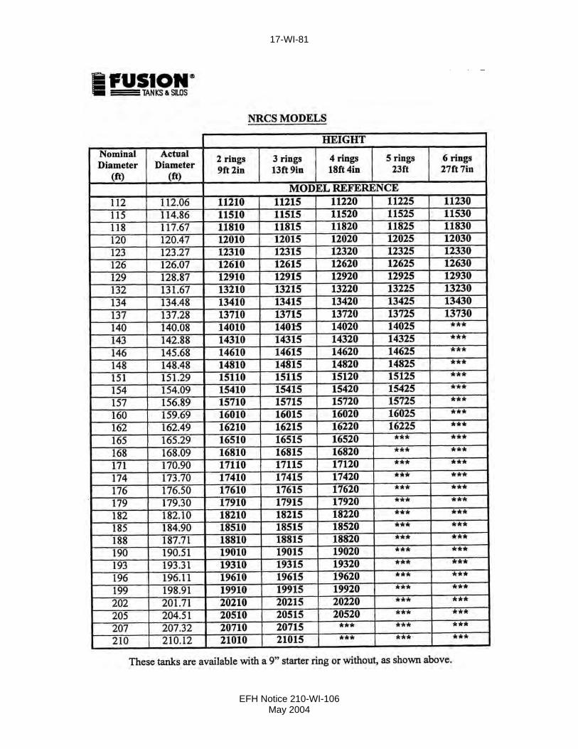
Model Reference Numbers and structure sizes are contained in the attached tables.
Drawings and Installation Manual:
The construction drawings are proprietary and not for distribution.
The drawings will be available on site. The Agricultural Products Slurry Tank Construction Guide, 32 pages, dated April 28, 2000 will also be available on site.
Materials: The structure shell consists of glass fused to steel sheets that are bolted together. Footing walls and the floor slab are reinforced concrete. Cathodic protection is required on all installations.
• 4000 psi concrete • Maximum water-cement ratio of 0.46 • Grade 60 steel reinforcement • Expanding waterstop on the sheet or starter ring embedded in the
concrete footer.
Design Assumptions:
• The steel sheet design is for above ground application only (no backfill).
• Cathodic protection requirements are 1 (one) anode per 20 structure sheets.
• The concrete floor slab reinforcement will be determined by the installer based on the tank diameter to be constructed. Most slabs will be reinforced to allow a monolithic pour.
• The minimum required foundation soil bearing capacity is 3000 lbs./sq. ft.
Review and Acceptance:
An independent review of the structure design was performed by Baisch Engineering of Kaukauna, Wisconsin. They determined the design met the structural design requirements of NRCS Standard 313.
The State Conservation Engineer in Wisconsin accepted the independent engineering review and revisions to the construction guide for compliance with Wisconsin NRCS Standard 313.
EFH Notice 210-WI-106 May 2004

17-WI-80
EFH Notice 210-WI-106 May 2004
17-WI-81
EFH Notice 210-WI-106 May 2004
17-WI-82
EFH Notice 210-WI-106 May 2004

17-WI-83
WIESER’S PAN-L-BILT MANURE STORAGE FACILITY Owner and Manufacturer:
Wieser Concrete Products, Inc. W3716 U. S. Highway 10 Maiden Rock, Wisconsin 54750 715/647-2311 Toll Free 800/325-8456
Designer: Original designer: Addition features designer: Bernard J. Jahn, P. E. Michael J. Malson, P. E. Corcoran, Minnesota Mount Prospect, Illinois
Latest Standard 313 criteria designer: Greg A. Jewell, P. E. Spring Green, Wisconsin
Drawings and Installation Manual:
The construction drawings (43 pages) are in the document titled INSTALLATION MANUAL, PAN-L-BILT MANURE STORAGE FACILITY, April 9, 2001. The installation manual is signed and sealed by Joseph H. Marter, P.E. Page 4 of the installation manual has a revised date of 1/24/05.
Materials: • Wall panels are 8 or 12 feet high precast ribbed panels with 5000 psi concrete and Grade 60 steel.
• The cover slats and supporting beams and columns are precast with 5000 psi concrete and Grade 60 steel.
• Wall panels are bolted together with 5/8 inch bolts and sealed with Con-Seal Butyl Resin Concrete Sealant.
• Floor slab and footings are site cast with a minimum 3500 psi concrete and Grade 60 steel.
• Site soils and backfill requirements and options are listed in the Installation Manual.
Design Assumptions:
The wall panels are designed for a full backfill, tank empty condition, and a tank full condition with backfill one foot below the top of the wall panel. Equivalent fluid pressures are 65 psf for the manure and 60 psf and 85 psf for the soil backfill. An equipment surcharge loading equal to two feet of backfill soil (120 or 170 psf) is provided. A complete listing of loadings is contained on page 2 of the Installation Manual Drawings.
The cover slats, free stall panels, drive through panels or pump out covers are required to support the wall panels. Slats or cover panels and cover opening options are contained in the manual.
See “Review and Acceptance” on the back of this page for additional site soil requirements.
EFH Notice 210-WI-111 May 2006
17-WI-84
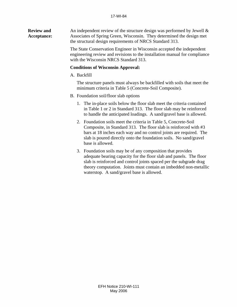
Review and Acceptance:
An independent review of the structure design was performed by Jewell & Associates of Spring Green, Wisconsin. They determined the design met the structural design requirements of NRCS Standard 313.
The State Conservation Engineer in Wisconsin accepted the independent engineering review and revisions to the installation manual for compliance with the Wisconsin NRCS Standard 313.
Conditions of Wisconsin Approval: A. Backfill
The structure panels must always be backfilled with soils that meet the minimum criteria in Table 5 (Concrete-Soil Composite).
B. Foundation soil/floor slab options
1. The in-place soils below the floor slab meet the criteria contained in Table 1 or 2 in Standard 313. The floor slab may be reinforced to handle the anticipated loadings. A sand/gravel base is allowed.
2. Foundation soils meet the criteria in Table 5, Concrete-Soil Composite, in Standard 313. The floor slab is reinforced with #3 bars at 18 inches each way and no control joints are required. The slab is poured directly onto the foundation soils. No sand/gravel base is allowed.
3. Foundation soils may be of any composition that provides adequate bearing capacity for the floor slab and panels. The floor slab is reinforced and control joints spaced per the subgrade drag theory computation. Joints must contain an imbedded non-metallic waterstop. A sand/gravel base is allowed.
EFH Notice 210-WI-111 May 2006

17-WI-85
AMERICAN STRUCTURES, INC. RELOCATION OF A.O. SMITH HARVESTORE “SLURRYSTORE” STRUCTURES
Fabricator: American Structures, Inc.
P. O. Box 409 Menomonie, WI 54751 (715) 235-4225
Designer: Stainless Steel Starter Ring Cathodic Protection Steven Poethke, P. E. Ralph W. Stephens, P. E. Cooper Engineering Co., Inc. Cathodic Protection Services Rice Lake, Wisconsin Houston, Texas Certification to present Standard 313 Timothy J. Auth, P. E. Auth Consulting Associates Menomonie, Wisconsin
Drawings and Installation Manual:
American Structures Inc., developed a specification titled “Relocation and Rebuilding Specification for Liquid Manure Storage Tanks”, revised May 2001. A copy may be obtained from the fabricator. Drawings and details are contained within this document. This specification covers the relocation of the following A. O. Smith Harvestore products:
Series Diameter Drawing No. 50A and 50B 25’ 253969 42’ 253970 62’ 253971 81’ 253972 101’ 253973 90 42’ 2-261283 62’ 2-261284 81’ 2-261285 101’ 2-261286
Materials: • The structure shell is glass fused to steel sheets. • The footing walls and floor are reinforced concrete. • The starter ring is stainless steel.
EFH Notice 210-WI-106 May 2004

17-WI-86
Assumptions: The following is a partial list of assumptions from the specification noted above. 1. The reconstructed unit is the same diameter and height as the
original installation. 2. All parts previously set in concrete are replaced with new parts,
equivalent to original equipment. 3. All hardware required for tank assembly will be new and
equivalent in size and strength to original equipment. 4. The agitation and unloading system enters the structure
through the floor slab. 5. A new cathodic protection system will be installed. 6. Concrete compressive strength will be 4000 psi. 7. Reinforcing bars will be Grade 60. 8. The starter ring is stainless steel, Type 304 with 0% cold reduction
strength values of Fy=40,000 psi and Fu-90,000 psi.
Review and Acceptance:
An independent review of the structure was performed by Auth Consulting Associates. They determined the design met the structural design requirements of Natural Resources Conservation Service (NRCS) Standard 313. The State Conservation Engineer in Wisconsin accepted the independent engineering review and revisions to the installation manual for compliance with Wisconsin NRCS Standard 313.
EFH Notice 210-WI-106 May 2004

17-WI-87
HUFFCUTT CONCRETE PRECAST CONCRETE T-PANELS FOR MANURE STORAGE
(8’-6”, 10’-6” AND 12’-6” High)
Fabricator: Huffcutt Concrete 737 Herbert Street Chippewa Falls, WI 54729 (715) 723-7446
Designer: Gary K. Munkelt, P. E. Gary K. Munkelt & Associates Souderton, Pennsylvania
Drawings and Installation Manual:
Gary K. Munkelt and Associates prepared a design, drawings and construction manual for precast concrete T-panels 8’-6”, 10’-6”, and 12’6” in height. The design and drawing documents show a latest revision date of May 11, 2004. The construction manual is dated March 2003. The design for all three panel heights were sealed and signed by Gary K. Munkelt, P.E. and dated May 13, 2004.
Materials: The structure is precast concrete, 5000 psi, reinforced with Grade 40 steel and 65,000 psi welded wire fabric. The floor slab is 3500 psi concrete.
The manure panels are bolted together with two layers of ¾”x1” Conseal CS-231 (or equivalent), controlled expansion sealant, placed between the units. Conseal CS-1500, elastomeric sealant (or equivalent) is applied to the inside and outside joint surface. A 12-inch wide Conseal CS-231 (or equivalent) will be installed at toe of each panel and extended 6 inches over the anchor bolt prior to pouring the concrete over the panel base.
Two 5-foot wide closure panels are used to complete the structure perimeter. A waterstop and horizontal reinforcing bars are cast into the closure panels and remain exposed to facilitate the closure concrete pour. Vertical reinforcement is added to match the adjoining precast panel reinforcement. The infill concrete is to be 4500 psi.
Design Assumptions:
The weight of the soil used in the design was 110 psf. A lateral earth pressure of 85 psf/ft of depth was assumed.
No concentrated loads due to machinery are allowed within 5 feet of the wall. A pumping dock design and access ramp details are included with the design submittal. The concrete strength used in this design is 4000 psi.
Pumping dock options include precast and poured in place construction details. This information is contained in the design submittal only and not in the construction manual.
EFH Notice 210-WI-107 July 2004
17-WI-88
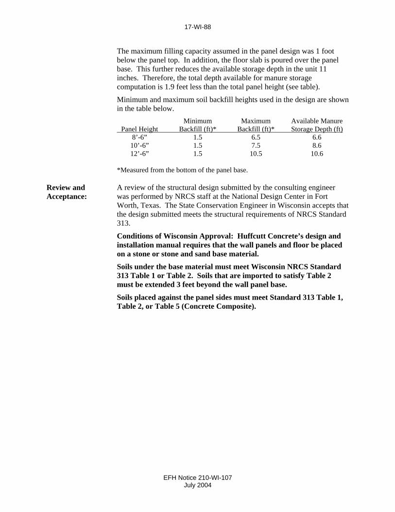
The maximum filling capacity assumed in the panel design was 1 foot below the panel top. In addition, the floor slab is poured over the panel base. This further reduces the available storage depth in the unit 11 inches. Therefore, the total depth available for manure storage computation is 1.9 feet less than the total panel height (see table).
Minimum and maximum soil backfill heights used in the design are shown in the table below. Minimum Maximum Available Manure Panel Height Backfill (ft)* Backfill (ft)* Storage Depth (ft) 8’-6” 1.5 6.5 6.6 10’-6” 1.5 7.5 8.6 12’-6” 1.5 10.5 10.6 *Measured from the bottom of the panel base.
Review and Acceptance:
A review of the structural design submitted by the consulting engineer was performed by NRCS staff at the National Design Center in Fort Worth, Texas. The State Conservation Engineer in Wisconsin accepts that the design submitted meets the structural requirements of NRCS Standard 313.
Conditions of Wisconsin Approval: Huffcutt Concrete’s design and installation manual requires that the wall panels and floor be placed on a stone or stone and sand base material.
Soils under the base material must meet Wisconsin NRCS Standard 313 Table 1 or Table 2. Soils that are imported to satisfy Table 2 must be extended 3 feet beyond the wall panel base.
Soils placed against the panel sides must meet Standard 313 Table 1, Table 2, or Table 5 (Concrete Composite).
EFH Notice 210-WI-107 July 2004

17-WI-89
HUFFCUTT CONCRETE PRECAST CONCRETE MANURE TROUGH 3’x10’x4’
Fabricator: Huffcutt Concrete
737 Herbert Street Chippewa Falls, WI 54729 (715) 723-7446
Designer: Gary K. Munkelt, P. E. Gary K. Munkelt & Associates Souderton, Pennsylvania
Drawings and Installation Manual:
Gary K. Munkelt and Associates prepared a design, drawings and installation instructions for the manure trough in a document titled, “Design Precast Concrete Manure Trough 3’x10’x4’ “with a latest revision date of 9/9/02. Pages 1 through 9 contain the design assumptions, design calculations and reinforcing steel drawings. Appendix A contains the installation instructions, drawings, and acceptable soil conditions for installations. The final submittal was sealed and signed by Gary K. Munkelt, P.E. and dated 9/9/02.
Materials: The structure is precast concrete, 4000 psi, reinforced with Grade 40 steel.
The manure gutter units are bolted together with Conseal CS-231 (or equivalent), controlled expansion sealant, and placed between the units. A hand troweled nonshrink grout is applied to the inside joint surface.
Design Assumptions:
The manure trough sides and bottom are designed with the most critical scenario being the trough empty, full backfill condition. Tractor wheel loads of 5000 pounds were also applied.
The soil loading used was 85 psf/ft equivalent fluid pressure.
The manure trough cover slab can be 4 feet below grade.
Review and Acceptance:
A review of the design submitted by the consulting engineer was performed by NRCS staff. The State Conservation Engineer in Wisconsin accepts that the design submitted meets the structural requirements of NRCS Standard 313.
Condition of Wisconsin Approval: To meet the requirements of Wisconsin NRCS Standard 313, the manure trough must be installed on sites with soils that meet the criteria in Standard 313 Table 1, or be placed on and backfilled with soils that meet the criteria of Table 2 or Table 5 (Concrete Composite) in Standard 313.
EFH Notice 210-WI-106 May 2004

17-WI-90
HUFFCUTT CONCRETE PRECAST CONCRETE SAND GUTTER 3’x12’x3’
Fabricator: Huffcutt Concrete
737 Herbert Street Chippewa Falls, WI 54729 (715) 723-7446
Designer: Gary K. Munkelt, P. E. Gary K. Munkelt & Associates Souderton, Pennsylvania
Drawings and Installation Manual:
Gary K. Munkelt and Associates prepared a design, drawings and installation instructions for the manure gutter in a document titled, “Design Precast Concrete Sand Gutter 3’x12’x3’ “dated 5/9/03. Pages 1 through 11 contain the design assumptions, design calculations and reinforcing steel drawings. Appendix A contains the installation instructions, drawings, and acceptable soil conditions for installations. The final submittal was sealed and signed by Gary K. Munkelt, P.E. and dated 5/9/03.
Materials: The structure is precast concrete, 4000 psi, reinforced with Grade 40 steel. The sand gutter units are bolted together with Conseal CS-231 (or equivalent), controlled expansion sealant, and placed between the units. A hand troweled nonshrink grout is applied to the inside joint surface.
Design Assumptions:
The sand gutter sides and bottom are designed with the most critical scenario being the gutter empty, full backfill condition. Tractor wheel loads of 5000 pounds were also applied.
The soil loading used was 85 psf/ft equivalent fluid pressure.
The sand gutter cover slab can be 2 feet below grade.
Review and Acceptance:
A review of the design submitted by the consulting engineer was performed by NRCS staff. The State Conservation Engineer in Wisconsin accepts that the design submitted meets the structural requirements of NRCS Standard 313.
Condition of Wisconsin Approval: To meet the requirements of Wisconsin NRCS Standard 313, the sand gutter must be installed on sites with soils that meet the criteria in Standard 313 Table 1, or be placed on and backfilled with soils that meet the criteria of Table 2 or Table 5 (Concrete Composite).
EFH Notice 210-WI-106 May 2004
17-WI-91
EFH Notice 210-WI-123 September 2011
CST STORAGE (FORMERLY ENGINEERED STORAGE PRODUCTS COMPANY)
(FORMERLY A. O. SMITH HARVESTORE PRODUCTS, INC.)
Designer and Manufacturer:
CST Storage Division of CST Industries, Inc. 345 Harvestore Drive DeKalb, IL 60115 (815) 756-1551
Product Name Slurrystore
Drawings and Installation Manual:
CST Stoprage will provide a design and drawings for a storage tank that is specific to the client’s need for storage volume and possible tank expansion. These structural detail drawings must be included in a site plan prepared by others. CST Storage will be assuming all responsibility for the compliance of the Slurrystore tank with the structural and foundation requirements of NRCS Standard 313. A CST Storage engineer licensed in Wisconsin will stamp and sign the cover sheet of each submittal package along with the following statement:
“The design in this submittal package complies with the national NRCS Waste Storage Facility Standard (Code 313) criteria for fabricated structures, including foundations, liquid tightness, structural loadings, structural design, and slabs on grade.”
The installation manual titled “Slurrystore Structure Construction Manual,” copyright 2005 is to be available from the fabrication crew on-site. This manual covers all the 90-Series, 96-Series, and 2000-Series Structures.
Materials: The structure shell consists of glass fused to steel sheets that are bolted together.
Footing walls and floor are to be 3500 psi concrete in accordance with Wisconsin Construction Specification 4, Concrete.
Cathodic protection is required and is provided by zinc anodes electrically connected to the shell sheets and the floor and footing reinforcement.
Foundation sheets contain a two-part continuous seal. The upper sealant is a gray seal strip. Directly below is a black bentonite seal strip. This bentonite strip may also be used for sealing pipe penetrations through the concrete floor. The seal strip materials are not to be applied to the sheets or pipe penetrations at temperatures below 20ºF.

17-WI-92
EFH Notice 210-WI-123 September 2011
Design Assumptions:
1. The shell design assumes above ground application only (no backfill). A specific site design may be provided by CST Storage that allows a limited backfill.
2. The footing strength design is based on a minimum 3000 psi concrete strength.
3. The final concrete floor slab reinforcement will be determined by the installer based on the tank diameter to be constructed. Most slabs will be reinforced to allow a monolithic pour.
The soil bearing capacity under the structure must be a minimum of 2000 psf or the bearing strength required in the CST design. This determination is the responsibility of a competent engineer retained by the owner.
Construction Certification:
The CST Storage licensed engineer who certified the design will also certify that the completed installation meets the manufacturer’s plans and specifications, based on the certification of the trained dealer who performed the installation. The following statement will suffice to document the certification of the Slurrystore tank installation, along with the stamp of the Wisconsin licensed engineer:
“To the best of my professional knowledge, judgment, and belief, the storage tank has been installed in accordance with the construction drawings and specifications and meets the national NRCS Waste Storage Facility Standard (Code 313) criteria for fabricated structures.”
NRCS Review and Approval:
The State Conservation Engineer in Illinois has concurred in an independent review performed by a consultant that the structural design is in accordance to NRCS Standard 313 for the 90-Series and 96-Series. The 2000-Series tanks are designed using the same principles as the previously approved tanks.
The Illinois State Conservation Engineer accepted the “one-at-a-time” business design model employed by Engineered Storage Products Company in a letter dated May 15, 2008.
The State Conservation Engineer in Wisconsin concurs in the use of this procedure.

17-WI-93
PIPPING CONCRETE
Owner and Fabricator:
Pipping Concrete, Inc. N5888 Center Road Brandon, WI 53919
Designer: James W. Todd, P.E. Excel Engineering, Inc. Fond du Lac, WI
Drawings: Excel Engineering will provide a design and drawings for a storage tank that is specific to the client’s need for storage volume. These structural details must be included in a site plan prepared by others. Excel Engineering will be assuming responsibility for the compliance of the tank with the structural and foundation requirements of NRCS Standard 313. An engineer from Excel Engineering licensed in Wisconsin will stamp and sign the cover sheet of each submittal package along with the following statement:
“The design in this submittal package complies with the NRCS Waste Storage Facility Standard (Code 313) criteria for fabricated structures, including foundation, liquid tightness, structural loadings, structural design, and slabs on grade.”
Material and Design:
The storage structures are reinforced concrete tanks. Circular tanks are available in various diameters and in heights of 12 or 16 feet. Rectangular tanks are available in heights of 12 feet. Access ramps into the storage tanks are an available option. Concrete strength required is 4000 psi at 28 days for the walls and floor slab. Grade 60 steel is utilized. The structure design will be based on soils at the site, surcharge requirements, and backfill conditions dictated by the site or needs of the operator.
EFH Notice 210-WI-117 August 2008

17-WI-94
Construction Certification:
The Excel Engineering, Inc., licensed engineer who certified the design will also need to certify that the completed tank installation meets the design and construction plans, based on the data provided by the Pipping superintendent of the site construction crew who performed the installation. The following statement will be sufficient to document the certification of the Pipping tank installation, along with the stamp of the licensed engineer:
“To the best of my professional knowledge, judgment and belief, the storage tank has been installed in accordance with the construction drawings and specifications and meets the NRCS Waste Storage Facility Standard (Code 313) criteria for fabricated structures.”
NRCS Review and Approval:
The NRCS National Design, Construction, and Soil Mechanics Center reviewed sample designs for circular and rectangular storage tanks. Their review concluded that the design meets the requirements of Standard 313. The State Conservation Engineer in Wisconsin accepted the “one-at-a-time” design business model employed by Pipping Concrete in a letter dated July 3, 2008.
EFH Notice 210-WI-117 August 2008

17-WI-95
WIESER’S L-PANEL MANURE STORAGE FACILITY Owner and Manufacturer:
Wieser Concrete Products, Inc. W3716 U. S. Highway 10 Maiden Rock, Wisconsin 54750 715/647-2311 Toll Free 800/325-8456
Designer: Original designer: (8’-6”) Reigstad & Associates St. Paul, MN
Latest Standard 313 criteria designer: (8’-6” and 12’) Greg A. Jewell, P. E. Spring Green, Wisconsin
Drawings and Installation Manual:
The construction drawings (26 pages) are in the document titled INSTALLATION MANUAL, L-PANEL MANURE STORAGE FACILITY, January 21, 2003, revised August 24, 2004. The installation manual is signed and sealed by Mark A. Wieser, P.E.
Materials: • Wall panels are 8’-6” or 12’ high precast ribbed panels with 5000 psi concrete and Grade 60 steel.
• Wall panels are bolted together with 5/8 inch bolts and sealed with Con-Seal Butyl Resin Sealant (CS 102 or 202).
• Floor slab and footings are site cast with a minimum 3500 psi concrete and reinforced per Floor Type options shown in the Installation Manual.
• Wall panels are secured to the floor slab with anchor bolts of various diameters.
• Site soils and backfill requirements and options are listed in the Installation Manual.
Design Assumptions:
The wall panels are designed for a full backfill, tank empty condition, and a tank full condition with backfill 4 feet below the top of the wall for both the 8’6” and 12’ panels. Equivalent fluid pressures are 65 psf for the manure and 65 psf for the soil backfill. An equipment surcharge loading equal to two feet of backfill soil (130 psf) is provided. A complete listing of loadings is contained on page 2 of the Installation Manual drawings.
See “Review and Acceptance” on the back of this page for additional site soil requirements.
EFH Notice 210-WI-111 May 2006

17-WI-96
Review and Acceptance:
An independent review of the 8’-6” structure design was performed by Jewell & Associates of Spring Green, Wisconsin. They determined the design required only minor revisions to meet the structural design requirements of NRCS Standard 313.
The State Conservation Engineer in Wisconsin accepted the independent engineering review of the 8’-6” panel design and revisions to the installation manual for compliance with the Wisconsin NRCS Standard 313.
NRCS engineering staff performed a review of the 12’ structure design performed by Jewell and Associates and have determined it to be in compliance with Standard 313.
Conditions of Wisconsin Approval: A. Backfill
The structure panels must always be backfilled with soils that meet the minimum criteria in Table 5 (Concrete-Soil Composite).
B. Foundation soil/floor slab options
1. The in-place soils below the floor slab meet the criteria contained in Table 1 or 2 in Standard 313. The floor slab may be reinforced to handle the anticipated loadings. A sand/gravel base is allowed.
2. Foundation soils meet the criteria in Table 5, Concrete-Soil Composite, in Standard 313. The floor slab is reinforced with #3 bars at 18 inches each way and no control joints are required. The slab is poured directly onto the foundation soils. No sand/gravel base is allowed.
3. Foundation soils may be of any composition that provides adequate bearing capacity for the floor slab and panels. The floor slab is reinforced and control joints spaced per the subgrade drag theory computation. Joints must contain an imbedded non-metallic waterstop. A sand/gravel base is allowed.
EFH Notice 210-WI-111 May 2006

17-WI-97
EFH Notice 210-WI-124 September 2011
NORTHERN CONCRETE
Owner and Fabricator:
Northern Concrete, Inc. 6601 County Road R Denmark, WI 54208
Designer: Conestoga-Rovers & Associates Green Bay, WI
Drawings: Conestoga-Rovers & Associates (CRA) will provide a design and drawings for a storage tank that is specific to the client’s need for storage volume. These structural details must be included in a site plan prepared by CRA or others. CRA will be assuming responsibility for the compliance of the tank with the structural and foundation requirements of NRCS Standard 313. An engineer from CRA licensed in Wisconsin will stamp and sign the cover sheet of each submittal package along with the following statement:
“The design in this submittal package complies with the NRCS Waste Storage Facility Standard (Code 313) criteria for fabricated structures, including foundation, liquid tightness, structural loadings, structural design, and slabs on grade.”
Material and Design:
The storage structures are reinforced concrete tanks. Circular tanks are available in various diameters and in heights of 12 feet. Access ramps into the storage tanks are an available option. Concrete compressive strength required is 4000 psi at 28 days for the walls and floor slab. Grade 60 steel is utilized. The structure design will be based on soils at the site, surcharge requirements, and backfill conditions dictated by the site or needs of the operator.

17-WI-98
EFH Notice 210-WI-124 September 2011
Construction Certification:
The CRA engineer licensed in Wisconsin who certified the design will also need to certify that the completed tank installation meets the design and construction plans. The following statement will be sufficient to document the certification of the installation, along with the stamp of the licensed engineer:
“To the best of my professional knowledge, judgment and belief, the storage tank has been installed in accordance with the construction drawings and specifications and meets the NRCS Waste Storage Facility Standard (Code 313) criteria for fabricated structures.”
NRCS Review and Approval:
The NRCS Upper Midwest Multi-State Design Team in Des Moines, Iowa, reviewed sample designs for circular storage tanks. Their review concluded that the design meets the requirements of Standard 313. The State Conservation Engineer in Wisconsin accepted the “one-at-a-time” design business model employed by Northern Concrete, Inc., and CRA in a letter dated September 20, 2011.