Menomonie Area School District Chemical Hygiene Plan (CHP ...

The development of a solar thermal water purification, heating, and power generation system: A case study.
Jerome E. Johnson, Ed.D.
Professor, Engineering and Technology Department Director, Center for Innovation and Development,
University of Wisconsin-Stout, Menomonie, WI [email protected]
Michael Cropp
Project Manager, Center for Innovation and Development, University of Wisconsin-Stout, Menomonie, WI
Commissioned by Mr. Diccon Fiore
Madison, WI
March 2009
Addendum
September 2009
2
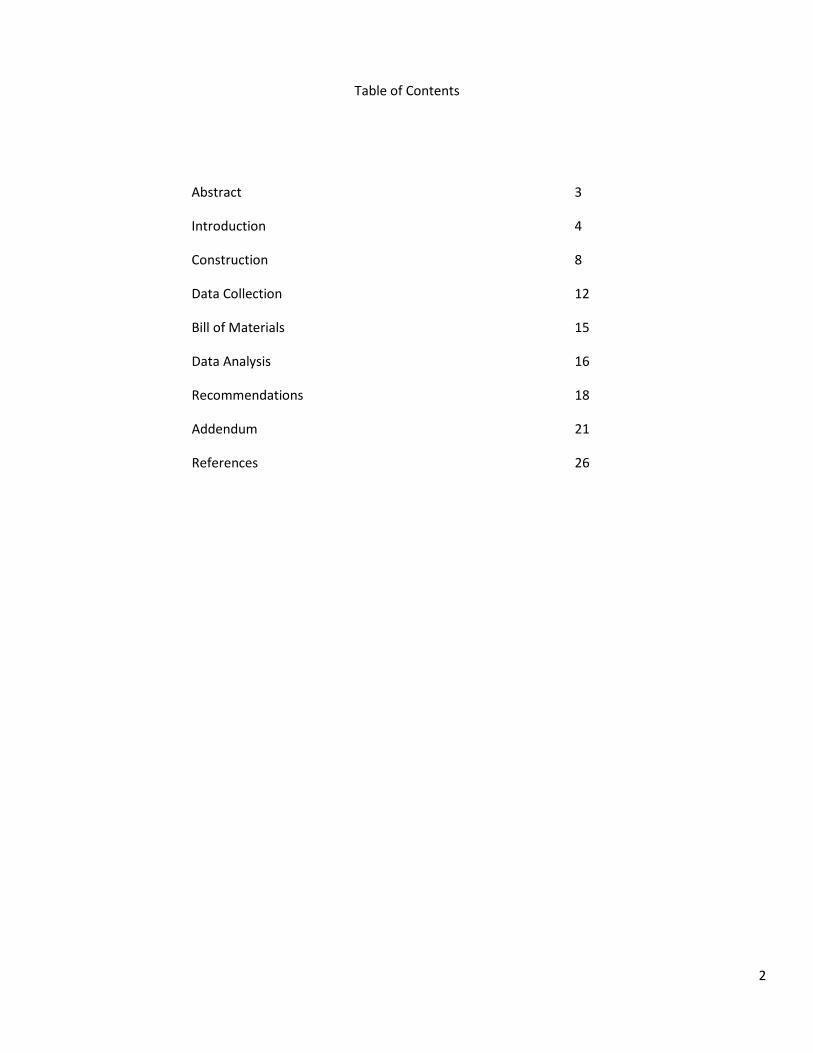
Table of Contents
Abstract 3
Introduction 4
Construction 8
Data Collection 12
Bill of Materials 15
Data Analysis 16
Recommendations 18
Addendum 21
References 26

3
Abstract:
The study conducted by the staff of the Center for Innovation and Development, University of Wisconsin-Stout, reduced- to-practice and confirmed the potential of an invention directed to a water purification system that also recovers power from generated steam. Water was the working fluid and was pumped from a reservoir to an array of 2- 4 foot by 8 foot parabolic solar troughs. A flow control valve adjustable for temperature and pressure, allowed the pressure within the troughs to build, thus increasing the boiling point of the water. At a temperature greater than 100 degrees Celsius, a saturated liquid stream passed through the valve into a vessel that was positioned at the focal point of sunlight within an 8 foot, 9 inch parabolic dish. The flash evaporation occurred, caused by a reduction in pressure on the downstream side of the flow control valve.
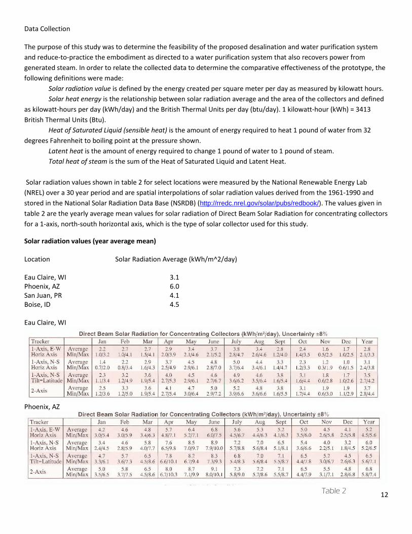
The National Renewable Energy Lab (NREL) over a 30 year period determined spatial interpolations of solar radiation values derived from 1961-1990, which are stored in the National Solar Radiation Data Base (NSRDB) (http://rredc.nrel.gov/solar/pubs/redbook/). The values given in table 2 are the yearly average mean values for solar radiation of Direct Beam Solar Radiation for concentrating collectors for a 1-axis, north-south horizontal axis, which is the type of solar collector used for this study. The yearly solar radiation average for Eau Claire, WI (data with closest proximity of actual testing) was 3.1 kWh/m^2/day. The solar heat energy was derived by multiplying the square footage of the system used for this study (10.6m^2) by the yearly solar radiation average value to achieve 32.86kWh/day. When converted to British Thermal Units the value was 112,162.1btu/day. Since 1200 btu/pound are required to change the state of water to steam, the solar heat energy of 112,162.1 btu/day is divided by 1200 to determine pounds per day (93.47). Thus, when converted to gallons per day, the amount of water vapor that should be produced by the system in Eau Claire, WI, based on the yearly average mean values, was 11.29 gallons.
The initial data for the study used three samples that were in the fall of 2008. The time needed to collect .25 gallons of distilled water was equated to gallons per day based on the available sunlight for the given test days. The average mean production of distilled water 4.69 gallons/day. This yielded a 41.5% efficiency (4.69/11.29). A more accurate efficiency assessment, though, used the data collected on October 31 and compared it to the solar radiation values for Eau Claire, WI using the October and November average mean of 1.75kWh/day. Using the most productive sample on October 31 of 4.99 gallons/day and comparing it to the theoretical output of 6.375 gallons/day, the system was 78.27% efficient and would produce 14.5kiloWatthours/day times the efficiency of the steam turbine. Flash evaporation has been implemented in several desalination systems through the use of coal or gas-fired boilers. To date, however, none of the existing concentrated solar power systems (trough, dish, and tower) that have been implemented on a commercial or demonstration basis make substantial use of flash evaporation to improve the efficiency of the respective systems as was done for the system used in this study. This phenomenon can be extremely useful, especially in sites not particularly well suited for concentrated solar power.
Further improvement to the system, and additional data collection and analysis were needed to determine the effectiveness of the system for power generation. Improvements to increase the efficiency of the system included the use of more reflective material for the parabolic troughs, methods to improve heat loss of the receiver pipe, preheating of supply water incorporated with rapid cooling of the condensate, and incorporation of methods to improve flash evaporation. The system, deployed as described above, produced approximately 5 gallons of distilled water per day. When compared to the 2008 data, the 2009 results were actually less notable given the improvements that were made. The primary basis supposed for this decline was the weather conditions during the 2009 collection samples, which were all partly cloudy skies. The data collected in 2008 was completed on days of mostly sunny skies.

4
Introduction
A water purification system proposal was conveyed to the staff of Center for Innovation and Development at the University of Wisconsin-Stout in November 2006 by Mr. Diccon Fiore with the intent of determining feasibility. The desalination system originally combined the methods of evaporation and distillation, thus the term “evapodis.” The impetus for this method of desalination originated with the perceived need for economical and reliable means of purifying surface water based on climate change models that showed a worsening of drought conditions and a rise in sea levels (http://news.bbc.co.uk/2/hi/science/nature/2943946.stm). The aim of the proposed system was not to compete with large-scale, industrial desalination and purification facilities, which are predominate in wealthy countries, but rather to provide a means of water purification in isolated communities in underdeveloped and arid regions. The purpose of this study was to determine the feasibility of the proposed system and reduce-to-practice the embodiment as eventually designed.
The description of the system included a solar-powered, evaporation and distillation apparatus intended to purify sea water that included the following components: a glass dome, an evaporation chamber, a vacuum chamber, and a condensation chamber with a refrigeration unit. The glass dome was to cover the evaporation and vacuum chambers. The evaporation chamber was a metallic, black spherical chamber with a bowl to hold sea water. As sunlight heated the chamber, was would evaporate and hot-moisture laden air would evaporate through an outlet connected to the vacuum chamber. A drain at the bottom of the bowl would open periodically to flush the brine. The vacuum chamber had an inlet portal at the bottom of a sphere and an exit portal at the top that was larger in diameter than the inlet portal. The process of the hot air exiting the chamber through a larger portal would create a vacuum in this chamber as well as the evaporation chamber. The purpose for this desired drop in pressure would be to decrease the effective boiling point of water, thus increasing the efficiency of the water purification system. The air vapor flowed from the vacuum chamber to the condensation chamber, which was cooled to increase the efficiency of distilling water.
A series of questions were posed by the client that included general inquiry into the sizing of the components, pumps, materials for vessels and the dome, effectiveness, and efficiency of the proposed system as compared to other systems. The Center staff reviewed the issues and analyzed the drawings and descriptions of the proposed system over a period of two months. The following conclusions were drawn: Materials for the pump, vessels, and dome were available. Yokota claimed to sell a pump whose components were made of stainless steel and could pump water linearly for 400 meters. Titanium was suggested as a material for the vessels, but the cost was prohibitive and did not adhere to American Society for Testing and Materials standards for pressure vessels. Dupont manufactured a polyester film called Tedlar that was resistant to heat and ultra violet degradation that would suffice as a covering for the geodesic dome. The sizing requirements for the evaporation and vacuum chambers were still indeterminate.
The primary competition for the proposed system was that of reverse osmosis. It is a filtration process that works by using pressure to force a solution through a membrane, retaining the solute on one side and allowing the pure solvent to pass to the other side. This is the reverse of the normal osmosis process, which is the natural movement of solvent from an area of low solute concentration, through a membrane, to an area of high solute concentration when no external pressure is applied. These systems are expensive to install and are dependent on high electrical resources. In addition, reverse osmosis systems use water to flush away impurities. Estimates vary between 3 to 10 gallons of water is used for flushing for every 1 gallon of filtered water produced.
The University of Missouri (http://extension.missouri.edu/xplor/envqual/wq0102.htm) indicated that water can be disinfected by boiling it, by adding oxidizing agents like chlorine or iodine, or by exposing it to ultraviolet light. Their tests indicated that boiling water was extremely effective as a disinfectant as compared to filtering and adding chemicals and

5
that boiling was the best method to make water safe to drink. This method will kill bacteria as well as other disease-causing microorganisms like Giardia lamblia and Cryptosporidium parvum, which are commonly found in rivers and lakes. At high elevations, though, the boiling point of water drops, so that extra boiling time is required. Water temperatures above 70 °C will kill all pathogens within 30 minutes, above 85 °C within a few minutes, and at boiling point (100 °C), most pathogens will be killed, excluding certain pathogens and their spores, which must be heated to 118 degrees Celsius (eg: botulism - Clostridium botulinum). This can be achieved by using a pressure cooker, as regular boiling will not heat water past 100 degrees Celsius. Chlorine kills bacteria, including disease-causing organisms and the nuisance organism, iron bacteria. However, low levels of chlorine, normally used to disinfect water, are not an effective treatment for giardia cysts. Ultraviolet (UV) light has disinfection properties that kill bacteria, viruses and some cysts. Neither chlorine nor ultraviolet light will kill giardia cysts.
It was also discovered that drinking the purest water was not always the best. Water has what some chemists call a “stability index”. This index indicates how stable water is in relation to the chemicals and minerals in its immediate environment. Water naturally seeks to achieve a zero or neutral index. If water has a positive index at a given temperature, it will tend to release or precipitate minerals that are dissolved in it. Water having a strongly positive stability index (for example hard water) deposits scale in pipes or hot water heaters. Water that is on the negative side of the index is aggressive and prone to dissolving minerals and metals from its immediate environment. Evidence of such water is shown by its ability to corrode pipes or produce rust. The more negative the index, the more aggressive the water is. Water produced from distillation and reverse osmosis has an extremely negative stability index. This water also actively absorbs carbon dioxide from the air and makes the water more acidic. When one drinks small quantities of this water for short periods of time, it has the special property of being able to absorb toxic substances in the body and remove them. This detoxification can be good for the body and can aid it in recovering from long-term exposure to certain contaminants. However, regular and long-term consumption of ultra-pure, de-mineralized water will also strip the body of magnesium, calcium and trace minerals. The more the mineral loss, the greater the risk of osteoporosis, osteo-arthritis, hypothyroidism, coronary artery disease, high blood pressure and a long list of degenerative diseases generally associated with premature aging (http://www.wellness-water-filter.com/dis_rev.html).
A further investigation into the relationship of pressure and temperature of liquids revealed that all liquids, at any temperature, exert a certain vapor pressure. The vapor pressure increases with temperature, because at higher temperature the molecules are moving faster and more able to overcome the attractive intermolecular forces that tend to bind them together. Boiling occurs when the vapor pressure reaches or exceeds the surrounding pressure from the atmosphere or whatever else is in contact with the liquid. At standard atmospheric pressure (1 atmosphere = 0.101325 megapascals = 14.706 pounds per square inch), water boils at approximately 100 degrees Celsius. That is simply another way of saying that the vapor pressure of water at that temperature is 1 atmosphere. At higher pressures (such as the pressure generated in a pressure cooker), the temperature must be higher before the vapor pressure reaches the surrounding pressure, so water under pressure boils at a higher temperature. Similarly, when the surrounding pressure is lower (such as at high altitudes), the vapor pressure reaches that pressure at a lower temperature. For example, in the Denver, Colorado area of the U.S. where the elevation above sea level is approximately one mile (1600 meters), the atmospheric pressure is about 83% of a standard atmosphere, and water boils at approximately 95 degrees Celsius.
The relationship between vapor pressure and temperature (or, in an inverse relationship between boiling temperature and pressure) is called the vapor pressure curve. Water's vapor pressure curve is of great importance, since it determines the relationship between temperature and pressure in any process where water is going from a liquid to a vapor state or vice-versa.

6
In table 1, The International Association for the Properties of Water and Steam (IAPWS) listed the vapor pressure for water as a function of temperature as taken from the latest formulation for general and scientific use:
Table 1 Temperature Vapor pressure Celsius Fahrenheit Mega pascals (MPa) Pounds per square inch (psi) .01 32 .000612 .088 763 25 77 .00317 .536 639 50 122 .01235 1.791 216 75 167 .0386 5.598 100 212 .1014 14.706 150 302 .4762 69.066 200 392 1.555 225.533 250 482 3.976 576.670 300 572 8.588 1,245.584 350 662 16.529 2,397.328 373.946 705 22.064 3,200.112 The first value in the table is for water's triple point, which is the thermodynamic state where vapor, liquid, and solid coexist. The last value is for water's critical point. The critical point is the end of the vapor pressure curve; there the vapor and liquid phases become identical and at higher temperatures there is only a single fluid phase of gas (http://www.iapws.org/). Of primary concern for the proposed system was whether the water vapor would be free of contaminates since it was boiled in a vacuum at a temperature less than 100 degrees Celsius. Of further concern was the cost effectiveness of the system. It was apparent that a geodesic glass dome could be constructed effectively to heat the water in the chamber but that the cost of using a metallic substance such as titanium for the vessels would be prohibitive. It was theorized that a more efficient means of collecting high gain solar energy could be obtained by the use mirrors to reflect and concentrate sunlight onto a receiver that collected the solar energy and converted it to heat. The conjecture for the concentrating factor of parabolic trough using 4 foot wide material would be approximately 40:1. The concentrating factor for an 8 foot parabolic dish was estimated at approximately 275:1. An investigation commenced that addressed these concerns. In addition, the notion of using the heat for purposes beyond distilling water was examined.
Research and Development
The Center staff determined that the proposed system for desalination of water had merit but was probably not feasible to construct and implement in a cost-effective manner in its current configuration. An investigation into a more effective manner of distilling water commenced by researching existing systems for concentrating solar energy. This became a compelling notion for several reasons, because most notably the heat generated by the solar concentrator could be used to distill water and also operate a conventional power cycle, for example through a steam turbine or a Sterling engine. Further, solar heat collected during the day could also be stored in liquid or solid media like molten salts, ceramics, and concrete. At night, it could be extracted from the storage medium and, thus, continue turbine operation.

7
The review of literature revealed that concentrating solar thermal energy is used to produce renewable heat or electricity through the use of lenses or mirrors and tracking systems to focus a large area of sunlight into a small beam. The concentrated light is then used as heat or as a heat source for a conventional power plant. The most developed concentrating solar thermal systems are the solar trough, parabolic dish, and solar power tower. Each concentration method is capable of producing high temperatures and correspondingly high thermodynamic efficiencies, but they vary in the way that they track the sun and focus light. A solar trough consists of a linear parabolic reflector that concentrates light onto a receiver positioned along the reflector's focal line. The reflector follows the Sun during the daylight hours by tracking along a single axis. A working fluid is heated to 150-350 °C as it flows through the receiver and is then used as a heat source for a power generation system. Trough systems are the most developed Concentrated Solar Power (CSP) technology. The solar energy generating systems plants in California, Acciona's Nevada Solar One near Boulder City, Nevada, and Plataforma Solar de Almería's SSPS-DCS plant in Spain are representative of this technology. A parabolic dish or dish engine system consists of a stand-alone parabolic reflector that concentrates light onto a receiver positioned at the reflector's focal point. The reflector tracks the Sun along two axes. The working fluid in the receiver is heated to 250-700 °C and then used by a Stirling engine to generate power. Parabolic dish systems provide the highest solar-to-electric efficiency among CSP technologies, and their modular nature provides scalability. The Stirling Energy Systems and Science Applications International Corporation dishes at University of Nevada-Las Vegas and the Big Dish in Canberra, Australia are representative of this technology. A solar power tower consists of an array of dual-axis tracking reflectors (heliostats) that concentrate light on a central receiver atop a tower; the receiver contains a fluid deposit, which can consist of sea water. The working fluid in the receiver is heated to 500-1000 °C and then used as a heat source for a power generation or energy storage system. Power tower development is less advanced than trough systems, but they offer higher efficiency and better energy storage capability. The Solar Two in Daggett, California and the Planta Solar 10 (PS10) in Sanlucar la Mayor, Spain are representative of this technology. A proposal was made to the client that enabled further research on concentrated solar energy and to address the concern of not heating the water high enough to kill most bacteria. This proposal included heating the water with pressure greater than that of atmospheric pressure, then allowing the condensate to escape to a vessel that was at atmospheric pressure. This would force the water to be heated to a temperature greater than 100 degrees Celsius then be released into a vessel for what is referred to “flash evaporation”. The resulting steam would then be used to turn a steam turbine and also condense to distilled water. In order to confirm this concept, a contract was let between the university and the client calling for, among other things, the reduction-to-practice of the desalination and purification system as described in the provisional patent. The proposed system was a hybrid of the solar trough and solar dish systems. Discussion ensued between the client, the Center director, and patent agent Dr. Tipton Randall to develop a provisional patent application. The summary of the provisional patent developed by the participants is given below and the schematic of the system is shown below in Figure 1:
The invention is directed to a water purification system that also recovers power from generated steam. Saltwater is pumped (2) from a reservoir (1) to an array of parabolic solar troughs (3), shown as heaters in parallel. A flow control valve (4), adjustable for temperature and pressure, allows the pressure within the troughs to build, thus increasing the boiling point of the water. At a temperature greater than 100 degrees centigrade, a saturated liquid stream passes through the valve into a vessel (6) (water trap) that is positioned at the focal point of sunlight within a parabolic dish (5). The flash evaporation then occurs, caused by a reduction in pressure on the downstream side of the flow control valve (4). Some of the residual water that flows to the vessel evaporates, due to the vessel’s position at the focal point of the dish. Salty water that does not vaporize is discharged through the bottom of the water trap (6) to a reservoir (7). The

8
steam exits the top of the vessel and flows through a flow-dividing valve (8). A portion of the steam drives a steam turbine (9)(Tesla turbine), and the remaining steam is condensed in a cooler (10) equipped with a flexible, coiled line (11). The condensed vapor flows into a reservoir (12), which contains salt-free, potable water. The steam that exits the turbine (9) flows to a heat exchanger (13) to preheat the initial salt water in the reservoir (1).
Construction
The development of the components to the system commenced with construction of a ten foot long, parabolic trough. A sheet of 4 foot by 10 foot 16 gauge aluminum was held in place by a series of plywood forms (see Figure 2), each having a groove cut into the shape of a parabola. A mirror film was secured to the aluminum with spray adhesive. A 1 inch diameter copper pipe was inserted into a hole located at the focal point of the parabola on each form. The pipe was supported on the ends of the trough with a wooden brace. This brace supported the pipe, forms, and entire parabolic trough. The trough rotated about the pipe (see Figure 3).
Figure 1
Figure 3 Figure 2

9
The trough was manually positioned to focus the sunlight to the copper pipe receiver. When out of focus, excessive sunlight noise was shown on the plywood forms (see figure 4). The system was filled with one gallon of water. The trough was manually positioned to absorb sunlight. Steam was evident after 15 minutes. In preparation for further development, linear actuators were secured from Venture Manufacturing, Co., Dayton, OH (Standard Satellite Actuator, Mini T-24) as was sun tracking circuitry by Red Rock Energy, LLC (www.redrok.com) (see figure 5).
A second trough (see figure 6) was constructed using ¾” plywood and 2”x6” support members. As with the first trough, a sheet of 16 gauge steel, in this case measured 4 foot by 8 foot was held in place by a series of plywood forms. Only the end forms had a groove cut into the shape of a parabola to secure the steel. The middle three forms only supported the steel from the bottom. A mirror film was secured to the steel with spray adhesive. A one inch diameter copper pipe was inserted into a hole located at the focal point of the parabola on each end form. The pipe was inserted into a bushing, which then was mounted to the plywood forms on each end with a bearing and housing.
The weight of the second trough was excessive (120 lbs) and it was not conducive for manufacturing on a large scale. It was determined that the next trough would be constructed of forms made from 14 gauge steel. A pattern was produced from 1/4” hardboard using a computer-numerical control router cut into the pattern shown in figure 7. This
Figure 6
Figure 4 Figure 5
Figure 7

10
pattern was adhered temporarily to the steel and served as a guide to cut the steel using a hand-held plasma cutter (see figure 8). A sheet of 16 gauge steel was used as a substrate for the mirror film. A 1” diameter copper pipe was passed through a bushing and bearing, mounted to the two end forms (see figure 9).
The formation of the parabolic dish portion of the system involved dismantling an aluminum dish and steel pole from an existing farmstead, transportation to the on-campus laboratory, cleaning, polishing, fabrication of – and assembly to a supporting base. In June 2008 the dish was transported to a rural, remote testing and fabrication site in order to maintain confidentiality. The weight and size of the dish (8’9” diameter) necessitated the use of a forklift at the on-campus laboratory for unloading, setup, and assembly. Later a skid steer was required for transport of the base and assembly of the dish to the base at the rural, remote testing facility.
A test was performed to determine the reflectivity of a powder coat chrome-colored paint. Once it was resolved that the paint would not provide the necessary reflectivity, 44 triangular pieces of mirror Mylar film were adhered to the dish. The original flash evaporation vessel, positioned at the focal point of the dish, was contrived from a 3 gallon air compressor tank (see figure 10). The position of the outflow condensation line proved to be inadequate for proper flow. Thus, construction on a new vessel, with properly positioned holes and fittings for inlet, outlet, and gauges commenced. The finished tank was installed prior to data collection.
The entire assembly was configured in September 2008. Figure 11 shows the system prior to application of mirror film and replacement of new tank. Two Standard Satellite Actuator actuators (Mini T-24) were installed Figure 10
Figure 9
Figure 8

11
on the dish to track the sun at the proper azimuth and altitude. One actuator was used to track the sun for trough #3. Trough #2 was positioned manually. A 12 volt, direct current battery was installed to power the actuators and a water pump. The system was then filled with approximately 5 United States gallons of water that was at 45 degrees Fahrenheit. Data collection commenced on September 16, 2008 and was repeated on October 31, 2008.
Figure 11
12
Data Collection The purpose of this study was to determine the feasibility of the proposed desalination and water purification system and reduce-to-practice the embodiment as directed to a water purification system that also recovers power from generated steam. In order to relate the collected data to determine the comparative effectiveness of the prototype, the following definitions were made: Solar radiation value is defined by the energy created per square meter per day as measured by kilowatt hours. Solar heat energy is the relationship between solar radiation average and the area of the collectors and defined as kilowatt-hours per day (kWh/day) and the British Thermal Units per day (btu/day). 1 kilowatt-hour (kWh) = 3413 British Thermal Units (Btu). Heat of Saturated Liquid (sensible heat) is the amount of energy required to heat 1 pound of water from 32 degrees Fahrenheit to boiling point at the pressure shown. Latent heat is the amount of energy required to change 1 pound of water to 1 pound of steam. Total heat of steam is the sum of the Heat of Saturated Liquid and Latent Heat. Solar radiation values shown in table 2 for select locations were measured by the National Renewable Energy Lab (NREL) over a 30 year period and are spatial interpolations of solar radiation values derived from the 1961-1990 and stored in the National Solar Radiation Data Base (NSRDB) (http://rredc.nrel.gov/solar/pubs/redbook/). The values given in table 2 are the yearly average mean values for solar radiation of Direct Beam Solar Radiation for concentrating collectors for a 1-axis, north-south horizontal axis, which is the type of solar collector used for this study.
Solar radiation values (year average mean) Location Solar Radiation Average (kWh/m^2/day) Eau Claire, WI 3.1 Phoenix, AZ 6.0 San Juan, PR 4.1 Boise, ID 4.5 Eau Claire, WI
Phoenix, AZ
Table 2

13
The components used for this study included approximately 24 lineal feet of 1” diameter copper pipe. Sixteen feet of the pipe was heated by the solar troughs. The remainder of the pipe was not insulated carrying water between the troughs and from the second trough to the dish. Approximately 6 lineal feet of steel pipe connected the copper pipe to the tank positioned at the focal point of the dish. The area of the components used, troughs and a dish, are shown using a plan view or foot print area. The substrate of each trough measured 48” x 96”. The troughs concentrate the solar radiation at approximately a 40:1 ratio and the dish concentrates at a 270:1 ratio. Table 3 shows the size of each component of the system. Size of solar collection system Area of troughs Width (inches) Length (inches) Area (in^2) Area (m^2) 40 96 3,840 2.477413 41 96 3,936 2.539349 Area of Dish Diameter (inches) Area (in^2) Area (m^2) 105 8,659.01 5.586448 Total area of concentrated solar (m^2) 10.60312 The solar heat energy is the relationship between solar radiation average and the area of the collectors, calculated by multiplying the area of the solar collectors and the solar radiation values. The measurements are converted to common units with respective outputs in kilowatt-hours per day (kWh/day) and the British Thermal Units per day (btu/day). These represent the perfect weather conditions and consistent sun tracking. Again, the solar radiation values are based on the 30 year averages from NREL. Solar Heat Energy KWh/day btu/day Eau Claire, WI 32.86995 112,162.1 Phoenix, AZ 63.619257 217,088.0 San Juan, PD 43.473161 148,343.5 Boise, ID 47.71404 162,814.6 The steam properties section is used to calculate how much steam the system is capable of producing per day. The system temperature was observed from 380 to 397 degrees Fahrenheit, thus the two table lines. To determine the pounds per day (lb per day) of steam generated, the btu/day value is divided by the total heat of steam value to give the lb per day. The lb per day value is converted into gallons to give the gal per day able to be produced. The two values of water able to be created are based on the weight of the water relative to its respective content. Fresh water is assumed pure hydrogen and oxygen. Sea water has a 3.5% content of chloride, sodium, sulfate, magnesium, calcium, potassium and other minor constituents. This translated into a .025 gram per milliliter weight gain for sea water, which means less
Table 3
Table 4

14
distilled water can per produced per pound of incoming sea water. Again, all these values assume the perfect weather conditions with confounding variables of the system removed.
Heat of Saturated Liquid: the amount of energy required to heat 1 pound of water from 32 degrees F to boiling point at the pressure shown. Latent heat: the amount of energy required to change 1 pound of water to 1 pound of steam (from table). Total heat of steam: the sum of the Heat of Saturated Liquid and Latent Heat.
Observed Saturated Steam Heat of Latent Total Heat Steam Temperature (degrees F) pressure (psi) Saturated Liquid (btu/lb) Heat (btu/lb) Steam (btu/lb)
397 225 372 828 1200 380 180 353 845 1198
In Eau Claire, WI, given the area of 10.6m^2 of the system used and the solar radiation average of 3.1 kWh/m^2/day, equals a solar heat energy of 32.86 kWh/day. When converted to British Thermal Units the value is 112,162.1 btu/day. Since 1200 btu/pound are required to change the state of water to steam, the solar heat energy of 112,162.1 btu/day is divided by 1200 to determine pounds per day (93.47). Thus, when converted to gallons per day, the amount of water vapor that should be produced in Eau Claire, WI was 11.29 gallons.
Three trials were used to capture distilled water during the fall of 2008. The test results are shown for the system that was created as described above. The three time studies measured the time it took to capture one quart of distilled water. This relationship is converted into a time per gallon relationship. The average gallons per day are the number of gallons the system can produce relative to the hours of sunlight available on the respective day. The efficiency was determined by comparing the actual gallons per day as compared to the calculated amount for Eau Claire, WI (5.25/11.29).
Time to capture .25 gallons Time per gallon Sunlight available Gallons per day Efficiency distilled water (hours) (hours) (hours) with given sunlight % 16-Sept-08 .63 2.53 13.30 5.25 46.50 31-Oct-08 .55 2.20 10.98 4.99 44.22 31-Oct-08 .72 2.87 10.98 3.83 33.93
Total amount of steam generated
Fresh Sea Eau Claire, WI lb per day 93.47 93.47
gal per day 11.29 11.02
Fresh Sea Phoenix, AZ
lb per day 180.91 180.91
gal per day 21.85 21.33
Table 5
Table 7
Table 6

15
Bill of materials Approximate list price for suggested, not prototyped, items to be used in manufacture of first 20 systems. Trough $ Suggested Supplier 14 gauge steel 50 McNeilus Steel, Inc., Dodge Center, MN Actuator 50 Venture Manufacturing, Co., Dayton, OH Tracking circuitry 50 Red Rock Energy, LLC, White Bear Lake, MN Copper pipe and fittings 60 Menards, Inc., Eau Claire, WI Bearings with mounts 60 Fleet Farm, Menomonie, WI Mirror acrylic 160 Esser Glass, Eau Claire, WI 430 Dish Actuators 100 Venture Manufacturing, Co., Dayton, OH Pole and base steel 100 McNeilus Steel, Inc., Dodge Center, MN Piping 50 Menards, Inc., Eau Claire, WI Tracking circuitry 100 Red Rock Energy, LLC, White Bear Lake, MN Snomo Mylar film 50 Neilsen Enterprises, Kent, WA Pressure vessel 250 KNG Mechanical, Chippewa Falls, WI 8’6”steel mesh dish 760 Skyvision, Inc., Fergus Falls, MN 1410 Suggested Accessories 12 volt direct current water pump 12 volt direct current Battery Containers Turbine: The Toroidal Intersecting Vane Machine, or TIVM, is a positive displacement expander that also offers the flow and power density features of a turbine.

16
Data Analysis
The purpose of this study was to determine the feasibility of the proposed desalination and water purification system and reduce-to-practice the embodiment as eventually designed. The Center staff determined that the initial proposed system for desalination of water had merit but was probably not feasible to construct and implement in a cost-effective manner in its current configuration. An investigation into a more effective manner of distilling water commenced by researching existing systems for concentrating solar energy. This became a compelling notion for several reasons, but most notably was that the heat generated by the solar concentrator could be used to distill water and also operate a conventional power cycle. An analysis of related and competitive systems was required in order to determine the comparative effectiveness of the proposed embodiment. The elements of a solar thermal power system include: a concentrator, a receiver, a method of storage or transport, and a power conversion system. The current concentrating solar thermal installations use one or more of the following concentrators: parabolic trough, parabolic dish, and solar tower, which plane mirrors (heliostats) mounted in a circular array focused on a solar tower, thus the name. In these tower systems, a working fluid (generally a high temperature synthetic oil or molten salt) is pumped through the receiver where it is heated to around 550oC. The heated fluid can then be used to generate steam for electricity generation. Other concentrators, such as Fresnel Lenses can also be used in a concentrating system. The Research Institute for Sustainable Energy, an Australian research centre at Murdoch University (http://www.rise.org.au/info/Tech/hightemp/index.html) indicated that parabolic dish systems are the most efficient of all solar technologies, at approximately 25% solar-to-grid efficient, compared to around 20% for other solar thermal technologies. Stirling Energy Systems (SES) holds the solar-to-grid efficiency record of 31.25% net efficiency. On Jan. 31, 2008, a team of engineers from SES and Sandia National Laboratories broke a 24-year-old record; achieving a conversion rate of 31.25 percent (85.6 kilowatts of thermal energy yield 26.75 kw of electricity for the grid). It was done with a dish consisting of a mosaic of 82 mirrors that fit together to form a 38-ft.-wide parabola. The mirrors’ precise curvature focuses light onto a 7-inch area of a Stirling engine. The Stirling engine is a closed-cycle system, using the heat of the sun to expand hydrogen gas, pushing a piston, which rotates a crankshaft to power an electrical generator. The hydrogen is cooled and condensed by a radiator, then sent back to the expansion cylinder (http://www.stirlingenergy.com/downloads/2008-11-01_Popular-Mechanics-Breakthrough-Award-Winner.pdf). Infinia Corporation successfully deployed a Stirling Solar product that produces 3kW alternating current using the reflected sunlight on a parabolic dish as the energy source. Their predictions were for 24 percent efficiency. Retail units were to be available mid-to-late 2009 following the establishment of the appropriate distribution channels. They anticipated the price of the product to be moderately below the price for a photovoltaic system producing the same kWh alternating current (http://www.infiniacorp.com).
Standard solar photovoltaic panels are generally 12 percent to 15 percent efficient at converting light to electricity, though some can go up to 22 percent. The Encyclopedia of Alternative Energy and Sustainable Living cites the ratio of electric power produced by a photovoltaic cell at any instant to the power of the sunlight striking the cell is typically about 9% to 14% for commercially available cells. The Solar Server http://www.solarserver.de/wissen/photovoltaik-e.html, suggests that monocrystalline silicon cells will attain between 14 and 17% efficiency in production. To produce a monocrystalline silicon cell, though, absolutely pure semiconducting material is necessary. Monocrystalline rods are extracted from melted silicon and then sawed into thin plates. This production process guarantees a relatively high level of efficiency but is comparatively much more expensive than the production of polycrystalline cells. In this process,

17
liquid silicon is poured into blocks that are subsequently sawed into plates. During solidification of the material, crystal structures of varying sizes are formed, at whose borders defects emerge. As a result of this crystal defect, the solar cell is less efficient. Solar server also suggests a theoretical maximum level of efficiency of 28% for crystal silicon. The data collected for this study were gathered in September and late October of 2008. The average mean efficiency rating (comparison of what was actually produced by way of steam versus what should have been produced in Eau Claire, WI) for the data collected was 41.55%. Given the solar radiation average of Eau Claire, WI of 3.1 kWh/m^2/day, and the solar heat energy of Eau Claire, WI of 32.86995 kWh/day based on the square footage of collector of 10.60312m^2, the total output of energy using the 41.55% average would be about 13.66 kWh/day in Eau Claire, WI. That value was based on three samples of 46.5, 44.22, and 33.93, respectively. The later sample was made late in the afternoon with distractions to prevent accurate manual movement of one of the troughs with the sun. When that sample was deleted, the average mean was 45.36%. Using the solar heat energy of Eau Claire, WI at 32.86995 kWh/day, this efficiency rating would yield 14.9kWh/day. The data for two samples were collected on October 31. Table 2 indicated that the solar radiation values for Eau Claire, WI for October was 2.3 kWh/m^2/day and was 1.2 kWh/m^2/day in November with average mean of the two months being 1.75. The 10.60312 m^2 area of the collectors would yield a solar heat energy value of 18.555 kWh/day or 63,334.325 btu/day. This would yield 52.779 lbs/day of water or 6.375 gallons (1 gallon of water equals 8.279 pounds). The most productive sample taken on October 31, yielded 4.99 gallons per day (see Table 7). The data revealed that the system was 78.27% efficient when compared to what should be expected from a 1 axis, north –south, horizontal axis concentrating solar collector. The kWh/day rating, though, would remain approximately the same (18.555 x .7827=14.5kWh/day). A more accurate assessment for the comparison of the actual solar radiation to the average mean values was to base the efficiency partly on the solar radiation values for a 1 axis, north-south horizontal concentrator and partly on a 2 axis concentrator. The total area of the concentrating system was 10.6m^2. The two troughs used for this study had a total area 5.0 m^2, which was slightly less than half (47.1%) of the total area of the system. The area of the solar dish was 5.6m^2 or 52.9% of the total area of the system. During the actual testing, the movement of the dish on one axis was performed by an electric actuator, while the movement of the second axis was completed manually, since I would not be necessary to alter it until the next day. Thus, a more accurate assessment of the data would be to use solar radiation values for a two axis device for 53% of the square footage of the system and use the solar radiation values for a 1-axis, north-south, horizontal axis for 47% of the square footage (see Table 8). Given that the yearly average values had a +-8% uncertainty factor, and to simplify the computational method, the two-axis solar concentrator radiation values for October and November in Eau Claire, WI, which were 3.1 and 1.9 kWh/m^2/day, respectively, and the October and November values for the 1 axis north-south horizontal axis of 2.3 and 1.2 kWh/m^2/day were used to determine the solar radiation. The average mean of these values was 2.125 kWh/m^2/day. Consequently, the 10.60312 m^2 total area of the collectors would yield a solar heat energy value of 22.53 kWh/day. Since 1 kilowatt-hour (kWh) = 3413 British Thermal Units (Btu), the solar heat energy value in btu’s would be 76,894.89. This would yield 64.079 lbs/day of water or 7.74 gallons. Again, if only the sample of 4.99 gallons per day was used to determine the efficiency of what should be condensed in Eau Claire, WI versus the amount that was actually condensed, the rating would be 64.5%. This again would not change the kWh production as 22.53 kWh/day x .645 equals 14.5 kWh/day.
Table 8

18
Recommendations
Of the approximately 24 lineal feet of 1” diameter copper pipe used in the system, only sixteen feet of the pipe was heated by the solar troughs. The remainder of the pipe was not insulated carrying water between the troughs and from the second trough to the dish. Approximately 6 lineal feet of steel pipe connected the copper pipe to the tank positioned at the focal point of the dish. Measures should be taken to reduce the amount of heat loss in the system during testing. This would include some form of insulation on the receiver pipe that was not being heated by the solar troughs and a reduction in the length of pipe not being heated. To achieve this end, a reconfiguration of the troughs should be done such that they are positioned end to end versus side to side. It was also recommended that the accuracy of the troughs to reflect a greater percentage of sunlight onto the receiver be improved. The use of 1/8” mirror acrylic instead of mirror film was recommended as one adaptation to the troughs. A test of the material revealed a significant reduction in “noise” and its implementation should improve the concentration factor from 40:1 to approximately 64:1. In addition, tilting the trough by raising the north end equal to the latitude should produce approximately a 12% increase in solar radiation value (see Table 8).
The system used for this study was a novel use of solar energy and the phenomenon of flash evaporation. Thermodynamically, flash evaporation occurs when a saturated liquid undergoes a sudden reduction in the surrounding pressure so that a part of the liquid immediately turns to vapor to regain equilibrium. The higher the pressure, the higher the boiling temperature will be and the higher the heat content. When the pressure is reduced, a certain amount of sensible heat is released. This excess heat is absorbed in the form of latent heat causing the liquid to “flash” into steam. The percentage of flash steam formed when discharging condensate to reduced pressure at 100psi was approximately 13%. At 225 psi (the maximum pressure determined during this study) the percentage of flash steam formed was approximately 19%. When the hot condensate under pressure in the system used for this study was released to a lower pressure, approximately 19% of it re-evaporated to flash steam. This occurred at the focal point of the dish, where a great degree of heat was also raising the sensible heat of the water stored in the flash evaporation vessel. However, when the flash evaporation occurred, it did so at the expense of the sensible heat of the liquid in the same container. So, even though the heat of the vessel to which the flash steam is discharged has a positive effect on the amount of flash evaporation that occurs, a determination should be made as to the amount of 45 degree Fahrenheit water, if any, that is initially placed in the flash evaporation chamber for effective use of the phenomenon. Mutair and Ikegami (2008) discovered that the rate of flash evaporation of a liquid jet is extremely faster than that of flowing superheated liquid in conventional evaporators. The literature also revealed that Koito Yasushi (2003) conducted An Experimental Study on Enhancement of Spray Flash Evaporation. This study suggested that to enhance the spray flash evaporation occurring in a superheated liquid jet ejected from a tubular nozzle into a low-pressure vapor zone, a piece of wire mesh was installed at the nozzle exit. Cavitations occur on the surface of the wire mesh and the nucleated bubbles are supplied to the liquid jet as bubble nuclei. The experimental results confirmed that the spray flash evaporation is enhanced by installation of the wire mesh, thereby increasing the evaporation efficiency. Consequently, the spray flash evaporation technique can be applied to various energy-saving systems utilizing a small temperature difference at comparatively low temperatures. Ikegami et al. (2006) investigated the influence of injection direction and confirmed that upwardly issuing jets have better performance and faster evaporation than those downwardly issuing jets due to the natural maxing effect occurring by the falling droplets. These changes to the system used in this study should be considered upon further implementation of the system. During this study, the steam left the flash evaporation vessel through an outlet port near the top of the vessel. It condensed by passing downward through an 8 foot, ½” diameter, coiled copper pipe. The condensate was then captured

19
in quart jars. A portion of the steam was released to atmosphere during the capture. The rate at which the steam condensed to water could have greatly been improved by cooling the coiled copper pipe in a water bath or adding fins to the copper to dissipate the heat. Additionally, measures must be taken in future experiments to reduce the inadvertent loss of steam at the condensate capture point. The temperature of the water that filled the system was approximately 45 degrees Fahrenheit. A method to preheat the water entering the system could be implemented by cooling the condensate with the supply water. The heat transfer would enable preheating of the supply water. The power generation expectation of 14.5 kWh/day times the efficiency of the turbine does not on face value appear adequate for implementation on a large scale, since the average power consumption per day may be anywhere from 14kWh/day to 36kWh/day for a 2000 square foot residential home. If, however, the home that uses 14kWh/day were to use photovoltaic cells to power the home, 285 square feet of cells (about 26 square meters) that would cost around $16,000 plus the price of a battery bank and inverter. The footprint of the system used for this study was approximately 160 square feet.
If the square footage of the solar thermal system were doubled, then too the power output would be doubled. The improvements listed above and a more thorough data collection will undoubtedly yield more promising results. Thus, it is recommended that further investigation be made into the potential implementation of the system for use as electrical power generation.
Several home water distillation systems are available commercially. The power source for many is 120 volts alternating current. The rates for distillation range from 1 gallon every 4 hours to 1 gallon every six hours. The power consumption for the Nutriteam Countertop is 580kW. It appears that the distillation rate of 5 gallons per day for the system studied for this report, based on approximately 11 hours of sunlight, is adequate for home water consumption.
Solar thermal power can only use direct sunlight, called beam radiation, which is not deviated by clouds, fumes, or dust in the atmosphere. The typical site regions for this technology are within less than 40 degrees of latitude north or south, while the testing for this study was conducted at 45 degrees north latitude. It should be noted that small solar thermal power generation plants are ideally suited to satisfy summer noon peak loads at more northerly latitudes. This could occur through the use of absorption chillers, which use heat instead of mechanical energy to provide cooling. Instead of using an electric motor for operating a compressor to raise the pressure of refrigerant vapors, and an absorption chiller uses heat for compressing refrigerant vapors to a high-pressure. An investigation should be made to determine the feasibility of implementing the system under study for implementation with an absorption chiller.
The on-going research of alternative power generation and desalinization systems using solar energy is evident by the studies being conducted throughout the world (http://www.nerc.gov.jo/events/AQUA-CSP/AQUA-CSP-Executive-Summary-English-01.pdf) and by the funding that the United States Department of Energy has made available (http://www1.eere.energy.gov/solar/csp_industry_projects.html#linear). It is strongly suggested that the client explore these and other funding opportunities to further exploit the system initially developed through this project. A complete business plan should also be completed as the system proposed in the study could be implemented with positive effects for the establishment of a start-up business. The manufacturers of the components should also be contacted to determine more accurate pricing and availability.

20
The proposed system holds promise for implementation and commercialization as an inexpensive, sustainable water purification device used in the upper Midwest of North America. The efficiency rate of solar radiation attained versus solar radiation of the 30 year average was quite significant at 78.27% for one of the samples collected. A consistent efficiency rate at that percentage would validate the potential of the proposed system. Further analysis is needed to determine the effectiveness of the system as an electrical power generation system for the same region. Further analysis is also needed to determine the effectiveness of the system as a supplemental thermal heating device.
Undoubtedly, the performance of the system would be more effective in lower latitudes as indicated by the solar radiation values indicated for Phoenix, AZ in table 2 and the implementation of the solar power generation facilities in southern California and Nevada. Given the imperfections of the prototype, however, the performance of the system under study can be greatly improved through subtle, yet imperative changes in production. Among these is the use of more reflective material for the parabolic troughs, methods to improve heat loss of the receiver pipe, preheating of supply water incorporated with rapid cooling of the condensate, and exploration of methods to improve flash evaporation.
Flash evaporation has been implemented in several desalination systems through the use of coal or gas-fired boilers. To date, however, none of the existing concentrated solar power systems (trough, dish, and tower) that have been implemented on commercial or demonstration basis make substantial use of flash evaporation to improve the efficiency of the respective systems as was done for the system used in this study. This phenomenon can be extremely useful, especially in sites not particularly well suited for concentrated solar power.
The use of concentrated solar thermal energy will be prevalent in the near future as a substantial contributor to the renewable energy options. Greenpeace International, the European Solar Thermal Industry Association and International Energy Agency’s SolarPACES (2005) http://www.greenpeace.org/raw/content/international/press/reports/Concentrated-Solar-Thermal-Power.pdf projected what could be achieved by the year 2025 given the right market conditions for concentrated solar thermal power generation. It was based on expected advances in solar thermal technology coupled with the growing number of countries which are supporting projects in order to achieve both climate change and power demand objectives. They predicted that by 2025 solar thermal technology will have emerged from a relatively marginal position in the hierarchy of renewable energy sources to achieve a substantial status alongside the current market leaders such as hydro and wind power and that the worldwide annual output of electricity generated by solar thermal systems should reach 100TerraWatthours/year.
21
Addendum September 2009
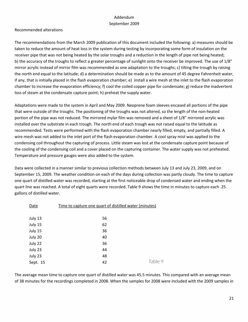
Recommended alterations The recommendations from the March 2009 publication of this document included the following: a) measures should be taken to reduce the amount of heat loss in the system during testing by incorporating some form of insulation on the receiver pipe that was not being heated by the solar troughs and a reduction in the length of pipe not being heated; b) the accuracy of the troughs to reflect a greater percentage of sunlight onto the receiver be improved. The use of 1/8” mirror acrylic instead of mirror film was recommended as one adaptation to the troughs; c) tilting the trough by raising the north end equal to the latitude; d) a determination should be made as to the amount of 45 degree Fahrenheit water, if any, that is initially placed in the flash evaporation chamber; e) install a wire mesh at the inlet to the flash evaporation chamber to increase the evaporation efficiency; f) cool the coiled copper pipe for condensate; g) reduce the inadvertent loss of steam at the condensate capture point; h) preheat the supply water. Adaptations were made to the system in April and May 2009. Neoprene foam sleeves encased all portions of the pipe that were outside of the troughs. The positioning of the troughs was not altered, so the length of the non-heated portion of the pipe was not reduced. The mirrored mylar film was removed and a sheet of 1/8” mirrored acrylic was installed over the substrate in each trough. The north end of each trough was not raised equal to the latitude as recommended. Tests were performed with the flash evaporation chamber nearly filled, empty, and partially filled. A wire mesh was not added to the inlet port of the flash evaporation chamber. A cool spray mist was applied to the condensing coil throughout the capturing of process. Little steam was lost at the condensate capture point because of the cooling of the condensing coil and a cover placed on the capturing container. The water supply was not preheated. Temperature and pressure gauges were also added to the system. Data were collected in a manner similar to previous collection methods between July 13 and July 23, 2009, and on September 15, 2009. The weather condition on each of the days during collection was partly cloudy. The time to capture one quart of distilled water was recorded, starting at the first noticeable drop of condensed water and ending when the quart line was reached. A total of eight quarts were recorded. Table 9 shows the time in minutes to capture each .25 gallons of distilled water. Date Time to capture one quart of distilled water (minutes) July 13 56 July 15 62 July 15 36 July 20 40 July 22 36 July 23 44 July 23 48 Sept. 15 42 The average mean time to capture one quart of distilled water was 45.5 minutes. This compared with an average mean of 38 minutes for the recordings completed in 2008. When the samples for 2008 were included with the 2009 samples in
Table 9

22
the calculation, the average mean time to collect .25 gallons of water was 43.45 minutes. All data collected for the study are shown in Table 10.
Test Results
Avg time to capture 0.25 gal distilled
water: Time per
gal
Time Solar Average Efficiency Power Radiation output comparison to output on test day per day Solar Radiation Values
min hr hr
Sunrise Sunset hr:min gallons % kwh/day
16-Sep 38 0.63 2.53
6:16 19:34 13:18 5.25 46.50 15.28
31-Oct 33 0.55 2.20
7:15 18:14 10:59 4.99 44.22 14.53 31-Oct 43 0.72 2.87
7:15 18:14 10:59 3.83 33.93 11.15
13-Jul 56 0.93 3.73
4:34 19:52 15:18 4.10 36.30 11.93 15-Jul 62 1.03 4.13
4:36 19:51 15:15 3.69 32.68 10.74
15-Jul 36 0.60 2.40
4:36 19:51 15:15 6.35 56.26 18.50 20-Jul 40 0.67 2.67
4:47 19:51 15:04 5.65 50.04 16.45
22-Jul 36 0.60 2.40
4:43 19:45 15:02 6.26 55.48 18.23 23-Jul 44 0.73 2.93
4:44 19:44 15:00 5.11 45.29 14.89
23-Jul 48 0.80 3.20
4:44 19:44 15:00 4.69 41.51 13.65 15-Sep 42 0.70 2.80 6:16 19:34 13:18 4.75 42.07 14.46
Average Mean
43.45
0.72 2.91
4.97 44.02 14.53
Discussion The data collected throughout the year of 2009 affirmed the results from 2008. The system, deployed as described above, produced approximately 5 gallons of distilled water per day. When compared to the 2008 data, the 2009 results were actually less notable given the improvements that were made. The primary basis supposed for this decline was the weather conditions during the 2009 collection samples, which were all partly cloudy skies. The data collected in 2008 was completed on days of mostly sunny skies. In Eau Claire, WI, given the area of 10.6m^2 of the system used and the solar radiation average of 3.1 kWh/m^2/day, equals a solar heat energy of 32.86 kWh/day. When converted to British Thermal Units the value is 112,162.1 btu/day. Since 1200 btu/pound are required to change the state of water to steam, the solar heat energy of 112,162.1 btu/day is divided by 1200 to determine pounds per day (93.47). Thus, when converted to gallons per day, the amount of water vapor that should be produced in Eau Claire, WI was 11.29 gallons. The average output per day was 4.97 gallons for a 44.02% efficiency rating. The total output of energy using the 44.02% average would be about 14.53 kWh/day in Eau Claire, WI.
Table 10

23
Solar Advisor Model is provided by the National Renewable Energy Laboratory ("NREL"), which is operated by the Midwest Research Institute ("MRI") for the Department Of Energy ("DOE") https://www.nrel.gov/analysis/sam/ . Inputs made into the Solar Advisor Model for a parabolic trough system with an SEGS 80Mw turbine, were made assuming a solar field of 500m^2, which resulted in a -5305 MWh net electrical power generated. The basis for the model was a 100MW baseline with parameterized storage. It was not until a solar field of 50,000m^2 was employed that the net electrical power generation reached 0MWh. A 500,000m^2 solar field area produced 76,703MWh. The Solar Advisor model estimated a total operating expense for this system to be $6,900,000 in year one. The Solar Advisor Model did not allow for inputs for a system smaller than a 100mW, nor did it allow for a hybrid system of parabolic troughs and dishes used for this study. Further, the software assumed that the system was for base power generating plant. The Transient Energy System Simulation Tool TRNSYS (pronounced 'tran-sis'), www.transys.com commercially available since 1975, is a flexible tool designed to simulate the transient performance of thermal energy systems. TRNSYS's beginnings can be found in a joint project between the University of Wisconsin-Madison Solar Energy Lab and the University of Colorado Solar Energy Applications Lab. In the 1970's a house was built in Colorado to study emerging solar energy technologies. The University of Wisconsin contributed by writing a Fortran program to predict the energy use in the building. Toward the very end of the project, when the Fortran programming graduate student was writing his thesis, a simple modification was made to the backup heating system in the house. Reworking the Fortran program took an inordinately long 8 weeks, delaying the student's graduation. In subsequent work, the University of Wisconsin developed a method of describing each component of and energy system as a Fortran subroutine having inputs and outputs. Anyone with a Fortran compiler could use the basic component format to model new technologies and quickly incorporate them into the TRNSYS library. Describing a complex energy system in TRNSYS, therefore, was reduced to a process of choosing the system components and hooking them together. More than 25 years later, TRNSYS is a well respected energy simulation tool under continual development by a joint team made up of the Solar Energy Laboratory (SEL) at the University of Wisconsin-Madison, The Centre Scientifique et Technique du Batiment (CSTB) in Sophia Antipolis, France, Transsolar Energietechnik GmBH in Stuttgart, Germany and Thermal Energy Systems Specialists (TESS) in Madison, Wisconsin. TRNSYS currently boasts a graphical interface, a library of 80 standard components, add on libraries offering over 300 other components, a worldwide user base and distributors in France, Germany, Spain, Sweden, Luxembourg, the US and Japan. TRANSYS is run within the Solar Advisor Model and when used on its own, appears to be able to accept inputs of lesser value. It is highly recommended that TRANSYS be explored as a more applicable modeling software for the system described for this report and that the client be trained in its use. Thermal Energy System Specialists (TESS) http://www.tess-inc.com/ offer the Transient Energy System Simulation Tool
software at a cost of $2,250 . TESS routinely offers training courses either on site at a customer’s location or at TESS in
Madison, Wisconsin. Training for the Transient Energy System Simulation Tool software is offered at the following rates :
Private tuition (2 days) TRNSYS Course Costs
Two Days
$US 1280
private tuition courses are typically custom tailored to address project specific issues.
Standard (3 day) TRNSYS Course Costs
$US 1200
$US 600 (per additional attendee)

24
At this juncture, September 2009, it appears that the possibility of generating electrical power with the described system is not feasible without significant input of resources for additional research and development and a set-aside of a sizable tract of land for deployment. The initial purpose, though, of this study was to determine whether purifying water with the described system holds practicability. It is the opinion of the researchers that the described system does indeed hold promise for water purification and that a manufacturing plan be devised. In addition, the system should be used as an auxiliary heater for an outdoor woodstove as a passive add-on system, especially for domestic water heating during the summer. The described system would also perform as a direct domestic water heating device using a solar-specific water heater with built-in heat exchanger. The system could also be installed as a solar space heating device. This would include incorporating a photovoltaic solar powered pump to move fluid through an inclined system to allow for full drainage during non-heating periods. It could be integrated into a present scheme using hydronic heating or a hybrid forced-air heating system. So, while the large utility corporations will continue to develop concentrated solar thermal electrical power systems, the present invention has considerable applications on a smaller scale. Since the utility patent application has been completed, it is highly recommended that the client seek to exploit the technology used in this study by pursuing additional funding from the United States Department of Energy. Specifically, grants and loans available from the Advanced Research Projects Agency-Energy (ARPA-E) http://www.arpa-e.energy.gov/ , the Loan Guarantee Solicitation Announcement https://www.fedconnect.net/fedconnect/PublicPages/PublicSearch/Public_Opportunities.aspx , and the Annual Phase I Small Business Innovation Research (SBIR) http://www.science.doe.gov/sbir/solicitations/FY%202010/C30_Notice.htm . The University should seek a right-to-use license for inclusion of this technology into its sustainability efforts. Exploitation of this and other energy-related projects conducted at the university in the recent past would gain significant notoriety for the client’s technology and improve licensing opportunities. Figures 12-14 depict the system in its state as of September 2009 with the figure 12 showing the most recently constructed flash evaporation tank being heated, figure 13 showing the two troughs incorporating mirrored acrylic and heat loss revisions. The entire system used for this study is shown in Figure 14.
Figure 12 Figure 13

25
Figure 14
26
References: Hutchinson, A. Solar’s New Dawn. Popular Mechanics. November, 2008 (http://www.stirlingenergy.com/downloads/2008-11-01_Popular-Mechanics-Breakthrough-Award-Winner.pdf). Ikegami, Y., Sasaki, H., Gouda, T., Uehara, H. “Experimental study on a spray flash desalination (influence of the direction of injection)” Desalination 194(1-3), pp. 81-98. 2006 Infinia, Corporation. (2008). Stirling Solar product that produces 3kW AC. http://www.infiniacorp.com. Greenpeace International, the European Solar Thermal Industry Association and International Energy Agency’s SolarPACES (2005). Concentrated Solar Thermal Power-Now. http://www.greenpeace.org/raw/content/international/press/reports/Concentrated-Solar-Thermal-Power.pdf The International Association for the Properties of Water and Steam. Aqueous Systems at Elevated Temperatures and Pressures: Physical Chemistry in Water, Steam and Hydrothermal Solutions. (2004). (http://www.iapws.org/). Kirby, A. (2003). Why world's taps are running dry. http://news.bbc.co.uk/2/hi/science/nature/2943946.stm). Mutair, S. and Ikegami, Y. (2008). Study and Enhancement of Flash Evaporation Desalination Utilizing the Ocean Thermo cline and Discharged heat. Sami and Proceedings of World Academy Of Science, Engineering And Technology Volume 33 September 2008 Issn 2070-3740 National Renewable Energy Lab. (2008). Solar Radiation Data Manual for Flat-Plate and Concentrating Collectors. National Solar Radiation Data Base . (http://rredc.nrel.gov/solar/pubs/redbook/). The Research Institute for Sustainable Energy. (2008). History of Concentrated Solar Energy Systems http://www.rise.org.au/info/Tech/hightemp/index.html) The Solar Server: Forum for Solar Energy. (2008). Photovoltaics: Solar Electricity and Solar Cells in Theory and Practice. http://www.solarserver.de/wissen/photovoltaik-e.html Trieb. F. (2007) Concentrating Solar Power for Seawater Desalination German Aerospace Center (DLR) Institute of Technical Thermodynamics Section Systems Analysis and Technology Assessment. http://www.nerc.gov.jo/events/AQUA-CSP/AQUA-CSP-Executive-Summary-English-01.pdf United States Department of Energy's Office of Energy Efficiency and Renewable Energy. (2008) Concentrating Solar Power Industry Projects. http://www1.eere.energy.gov/solar/csp_industry_projects.html#linear University of Missouri- Extension. (1995) Bacteria in Drinking Water. http://extension.missouri.edu/xplor/envqual/wq0102.htm) Water Wellbeing. (2008) Distilled vs. Reverse Osmosis. http://www.wellness-water-filter.com/dis_rev.html). Yasushi, Koito, 2003. An Experimental Study on Enhancement of Spray Flash Evaporation. Kagaku Kogaku Ronbunshu. Vol.29; No.1; Page150-153.