Fuji Electric-General-Purpose Inverter FVR-C11S-7EN Series ... · Fuji Electric-General-Purpose...
105
+PUVTWEVKQPOCPWCN Solutions for Drives Fuji Electric-General-Purpose Inverter FVR-C11S-7EN Series Single-phase 230V 0.1 - 2.2kW C11S FVR
Transcript of Fuji Electric-General-Purpose Inverter FVR-C11S-7EN Series ... · Fuji Electric-General-Purpose...

Solutions for Drives
Fuji Electric-General-Purpose Inverter FVR-C11S-7EN Series
Single-phase 230V 0.1 - 2.2kW
C11S
FVR
FVR-C11S-EN
Contents
Safety Instructions ................................... 1
1 Before Using This Product ........... 1-11-1 Receiving Inspections ................... 1-11-2 Appearance .................................. 1-21-3 Handling the Product .................... 1-31-4 Carrying ........................................ 1-41-5 Storage and transportation ........... 1-4
2 Installation and Connection ........... 2-12-1 Operating Environment ................. 2-12-2 Installation Method ........................ 2-22-3 Connection .................................... 2-3
2-3-1 Basic connection .................... 2-32-3-2 Connecting the main circuit
and ground terminals ............. 2-42-3-3 Connecting the
control terminals ..................... 2-62-3-4 Connection examples ........... 2-12
2-4 Others ......................................... 2-212-4-1 Harmonic component ........... 2-212-4-2 Noise .................................... 2-212-4-3 Leakage current ................... 2-21
3 Operation ............................................ 3-13-1 Inspection and Preparation
before Operation ........................... 3-13-2 Operation Method ......................... 3-13-3 Trial Run ....................................... 3-2
4 Keypad Panel .................................... 4-14-1 Names and Functions ................... 4-14-2 Operating Keypad Panel ............... 4-1
5 Selecting Function ........................... 5-15-1 Function Selection List .................. 5-15-2 Details of Each Function ............... 5-7
6 Protective Function ......................... 6-16-1 List of protective functions ............ 6-16-2 Alarm Reset .................................. 6-3
7 Troubleshooting ............................... 7-17-1 In case of tripping ......................... 7-17-2 Other trouble ................................. 7-7
8 Maintenance and Inspection .......... 8-18-1 Daily Inspection ............................. 8-18-2 Periodic Inspection ........................ 8-18-3 Electrical measurements
in the Main Circuit ......................... 8-58-4 Insulation Test ............................... 8-68-5 Parts Replacement ....................... 8-78-6 Inquiries about the Product and
Guarantee of the product .............. 8-7
9 Specifications .................................... 9-19-1 Standard Specifications ................ 9-19-2 Common Specifications ................ 9-29-3 Dimensions ................................... 9-89-4 Selection of Peripheral Device .... 9-11
10 Options ............................................ 10-110-1 Built-in Options ............................ 10-110-2 External Options ......................... 10-1
11 Applicable reactors ....................... 11-1
12 Compliance with standards ........ 12-112-1 UL/cUL standards [Applicable to
products with UL/cUL mark] ......... 12-112-1-1 General ................................. 12-112-1-2 Precautions ........................... 12-1
12-2 Compliance with EMC directive in EU [Applicable to products with CE mark] .............................. 12-2
12-2-1 General ................................ 12-212-3 Compliance with low voltage directive
in EU [Applicable to products with TÜV or CE mark] .................. 12-2
12-3-1 General ................................. 12-212-3-2 Precautions ........................... 12-2
13 ElectromagneticCompatibility (EMC) ....................... 13-113-1 General ....................................... 13-113-2 RFI Filters ................................... 13-113-3 Recommended Installation
Instructions .................................. 13-3

Safety Instructions 1
FVR-C11S-EN
Safety Instructions
Read this operation manual carefully and famil-iarize yourself with the operation of the inverterbefore installation, connection (wiring), opera-tion or maintenance and inspection of the de-vice. Be familiar with the inverter, safetyinformation, and safety signs before using the in-verter.In this instruction manual, safety signs are clas-sified into the following categories.
Note: More serious situations than those cov-ered by the CAUTION sign can resultdepending on the circumstances. It isimportant that you always follow the in-structions.
WARNINGImproper operation may result in death or serious injury.
CAUTIONImproper operation may result in slightto medium injury or property damage.

2 Safety Instructions
FVR-C11S-EN
Compliance with UL/cUL standards [Applicable to products with UL/cUL mark]
1. [WARNING] Take care of electric shock. Be sure to turn the inverter off before starting work.
2. [CAUTION] When the charge lamp is lit, the inverter is still chargedat a dangerous voltage.
3. [WARNING] There are two or more live parts inside the inverter.
4. The inverter is approved as a part used inside a panel. Install it in-side a panel.
5. Perform wiring to the input, output and control terminals of the in-verter, referring to the table below. Use UL certified round crimpterminal to the input and output terminals with insulation cover orcovered with reduced tube to obtain the insulation distance. Use acrimping tool recommended by the terminal manufacturer whenfabricating crimp terminals.
6. Install a fuse in the power supply to the inverter, referring to the ta-ble below.
Voltage Inverter type
Tightening torque [Nm]
Applicable wire diameter [AWG] (mm2)1)
Fuse[A] 2)
Recommended fuse
L1/L, L2/N U, V, W
Controlsection
L1/L, L2/N U, V, W
Controlsection
GouldCompany
BussmannCompany
Single-phase200Vinput
FVR0. 1C11S-7EN
1.20.4
14 (2.1)
20 (0.5)
6 A4J6 JKS6
FVR0. 2C11S-7EN 6 A4J6 JKS6
FVR0. 4C11S-7EN 10 A4J10 JKS10
FVR0. 75C11S-7EN 15 A4J15 JKS15
FVR1. 5C11S-7EN 12 (3.3) 30 A4J30 JKS30
FVR2. 2C11S-7EN 1.8 10 (5.3) 40 A4J40 JKS40
1) Use copper wires of allowable maximum temperature 60 or75 °C.2) Use UL certified "quick breaking fuse".
7. Connect the power supply satisfying the characteristics shown inthe table below as an input power supply of the inverter. (Shortcircuit rating)
Inverter type Input max. voltage Input current
FVR0. 1-2. 2C11S-7EN AC240V 5,000 A or less
CAUTION

Safety Instructions 3
FVR-C11S-EN
Compliance with low voltage directive in EU [Applicable to products with TÜVmark]
CAUTION
1. Safe separation for control interface of thisinverter is provided when this inverter is in-stalled in overvoltage category II. PELV(Protective Extra Low Voltage) circuit orSELV (Safety Extra Low Voltage) circuitfrom external controller is connected to theinterface directly.
2. Basic insulation for control interface of thisinverter is provided when this inverter is in-stalled in overvoltage category III. An insu-lation transformer has to be installedbetween power supply mains and this in-verter when SELV circuit from externalcontroller is connected to this inverter di-rectly. Otherwise supplementary insulationbetween control interface of this inverterand environment must be provided.
3. The ground terminal G should always beconnected to the ground. Don’t use onlyRCD as the sole method of electric shockprotection. Dimensions of external PE con-ductor should be same as dimensions ofinput phase conductor and capable forpossible fault.
4. Use MCCB or MC that conforms to EN orIEC standard.
5. Where RCD (Residual-current-operatedprotective device) is used for protection incase of direct or indirect contact, only RCDof type B is allowed on the supply side ofthis EE (Electric equipment). Otherwise an-other protective measure shall be appliedsuch as separation of the EE from the en-vironment by double or reinforced insula-tion or isolation of EE and supply systemby the transformer.
6. The inverter has to be installed in environ-ment of pollution degree 2. If the environ-ment is pollution degree 3 or 4, theinverter has to be installed in a cabinet ofIP54 or higher.
7. Use a prescribed wire according to theEN60204 Appendix C.
8. Install the inverter, AC or DC reactor, out-put filter in an enclosure that meets thefollowing requirement, to prevent a hu-man body from touching directly to theseequipment.
1) When a person can touch easily on eachconnecting terminal or live parts, installthe inverter, AC or DC reactor, output fil-ter in an enclosure with minimum de-gree of protection of IP4X.
2) When a person can not touch easily oneach connecting terminal or live parts,install the inverter, AC or DC reactor,output filter in an enclosure with a mini-mum degree of protection of IP2X.
9. It is necessary to install the inverter in ap-propriate method using an appropriateRFI filter to conform to the EMC directive.It is customer’s responsibility to checkwhether the equipment, the inverter is in-stalled in, conforms to EMC directive.

4 Safety Instructions
FVR-C11S-EN
Compliance with low voltage directive in EU [Continued]
Use of wires specified in Appendix C of EN 60204 is recommended.
Powersupplyvoltage
Nominalappliedmotor[kW]
Inverter type
Molded case circuit breaker (MCCB) or
earth leakagecircuit breaker
(ELCB)1)
Rated current [A]
Recommended wire size [mm2]
Input circuit 2)
single phase 200V [L1/L, L2/N]
Outputcircuit 2)
[U, V, W]
DCR 2)
circuit[P1]
[P(+)]
Controlwiring
WithDCR
Withoutreactor 3)
WithDCR
Withoutreactor 3)
Singlephase200V
0.1 FVR0. 1C11S-7EN
66
2.5 4)2.5 4)
2.5 4) 2.5 4)
0.5
0.2 FVR0. 2C11S-7EN
0.4 FVR0. 4C11S-7EN 10
0.75 FVR0. 75C11S-7EN 10 16
1.5 FVR1. 5C11S-7EN 16 20 4.0 4)
2.2 FVR2. 2C11S-7EN 20 32 4.0 5) 6.0 5) 2.5 5) 4.0 5)
1) The applicable frame and series of the molded case circuit breaker (MCCB) andearth leakage circuit breaker (ELCB) vary according to the capacity of thetransformer of the equipment. For details of selection, refer to the concerningtechnical documents.
2) The recommended wire size for the main circuit is the case for the low voltagedirective at ambient temperature 40 °C.
3) The power supply impedance without a reactor is considered to be theequivalent of 0.1% of the inverter capacity, with 10% current imbalanceaccompanied by the voltage imbalance.
4) Crimp terminals up to 7.4 mm in width (including tolerance) can be used.5) Crimp terminals up to 9.5 mm in width (including tolerance) can be used.6) Use the grounding cable of a size equal to or larger than that of the input power
supply cable.
CAUTION

Safety Instructions 5
FVR-C11S-EN
Instructions on use
Instructions on transport/installation
WARNING
1. This inverter is designed to drive a three-phase induction motor and is not usable fora single-phase motor or any other pur-poses.There is a risk of fire.
2. This inverter may not be used as is for anelevator, life-support system, or other pur-pose directly affecting the safety of hu-mans.Safety precautions should be establishedand practiced in terms of the entire system,rather than the independent device.Otherwise, an accident could occur.
WARNING
1. Attach the device to an incombustible ma-terial such as metal.Otherwise fire could occur.
2. Do not place the device near inflammables.Otherwise fire could occur.
CAUTION
1. Do not carry the device by holding just thesurface cover. Inverter may be dropped causing injury.
2. Do not allow foreign matter such as lint, pa-per dust, small chips of wood or metal, anddust to enter the inverter or adhere to theheat sink. Otherwise, a disaster such as burningcould occur.
3. Do not install or operate damaged inverteror an inverter with a missing part.Otherwise injury could occur.
4. Do not step on the product.Otherwise injury could occur.
5. When stacking up in tiers, do not exceedthe number of tiers indicated on the pack-ing carton.Otherwise injury could occur.

FVR-C11S-EN
6 Safety Instructions
Instructions on wiring
WARNING
1. When the inverter is connected to power,connect it via a line-protection molded casecircuit breaker or an earth-leakage circuitbreaker (Residual current operated protec-tive device).Otherwise fire could occur.
2. Be sure to connect the ground wire.Otherwise electric shock or fire couldoccur.
3. Ensure that a licensed specialistperforms the wiring work.
4. Check before starting the wiring that thepower is off (OPEN).Otherwise electric shock could occur.
5. Do not wire up the inverter until it has beeninstalled securely.Otherwise electric shock or injury couldoccur.
6. The inverter has to be grounded in accord-ance with the national and local safetyspecification.Otherwise electric shock could occur.
CAUTION
1. Check that the number of phases and therated voltage of this product correspond tothe number of phases and voltage of theAC power supply.Otherwise fire could occur.
2. Do not connect the AC power supply to theoutput terminals (U, V, W).Otherwise injury could occur.
3. Check the output terminals (U,V,W) for thephase order and connect them to the motorcorrectly.Otherwise fire could occur.
4. Do not connect a braking resistor directly tothe DC terminals [P(+), N(-)].Otherwise fire could occur.
5. Noise is generated from the inverter, mo-tor, and wiring. Take care that this noisedoes not cause malfunctions in peripheralsensors and equipment.Otherwise accidents could occur.

Safety Instructions 7
FVR-C11S-EN
Instructions on operation I
WARNING
1. Be sure to put on the surface cover beforeturning the power ON (CLOSE).Never remove the cover while the power isapplied to the inverter.Otherwise electric shock could occur.
2. Never operate switches with wet fingers.Otherwise electric shock could occur.
3. The interior of the inverter may remaincharged after turning off the power.Therefore, never attempt to remove thesurface cover except for wiring service andperiodic maintenance.Otherwise electric shock could occur.
WARNING
1. When the retry function is selected, the in-verter may automatically restart after trip-ping, depending on the cause of the trip. (Design the machine to secure personalsafety in the event of restart.)Otherwise accident could occur.
2. Operating conditions may occasionally bedifferent from the preset acceleration/de-celeration time or speed because of activa-tion of the stall prevention function.In such a case, personal safety must be se-cured through adequate machine design.Otherwise accident could occur.
3. The stop key is effective only when a func-tion setting has been established.Therefore install an emergency switch in-dependently. When operation via the ex-ternal signal terminal is selected, the STOPkey on the keypad panel will be disabled.There is a risk of accidents.
4. Operation starts suddenly if alarm reset isdone with an running signal input. Checkthat no running signal is input before alarmreset.Otherwise accidents could occur.
5. Never touch the inverter terminals whenenergized even if it has stopped.Otherwise electric shock could occur.
6. Never touch the keys on the keypad panelwith a pointed object such as a needle.Otherwise electric shock could occur.
CAUTION
1. Never touch the heat sink because theybecome very hot.Otherwise burns could occur.
2. The inverter can set high-speed operationeasily. Carefully check the limit of the mo-tor and machine before changing the set-ting.Otherwise injuries could occur.
3. Do not use the inverter brake function formechanical holding.Otherwise injuries could occur.

FVR-C11S-EN
8 Safety Instructions
Instruction on maintenance/inspection, and replacement
Instruction on disposal
General instructions
WARNING
1. Do not commence inspection work until atleast five minutes after the power has beenturned off (OPEN).(In addition, make sure that the chargelamp has gone off and check that the DCvoltage between terminals P(+) and N(-)does not exceed 25V DC.)Otherwise electric shock could occur.
2. Only qualified personnel should performmaintenance and inspection or replace-ment operations.(Take off all metal objects (watch, ring,etc.) before starting.)(Use well-insulated tools.)Otherwise electric shock or injury couldoccur.
3. Never modify the product.Otherwise electric shock or injury couldoccur.
CAUTIONSince this product contains lead solder,it must be treated as industrial wastewhen it is disposed of. Entrust it to awaste processing company when dis-posing it.
The figures in this operation manual mayshow the inverter with covers and safetyscreens removed to explain the structure indetails. Therefore, be sure to replace the cov-ers and screens to their original positions andoperate the inverter according to the instruc-tion manual.

1 Before Using This Product 1-1
FVR-C11S-EN
1
1 Before Using This Product
1-1 ReceivingInspections
Unpack and check the product as explained below.If you have any questions or problems with this product, please contactFUJI ELECTRIC Co., Ltd., or your local FUJI inverter distributor.
1) Check the ratings name plate to confirm that the delivered product isthe ordered one.
Figure 1-1-1 Ratings nameplate
TYPE: Inverter Type
FVR 0.75 C11S - 7 ENSeries Extension (EN series)Power voltage series: 7 Single-phase 200V input series
Series nameNominal applied motor: 0.75 0.75kWProduct type
SOURCE: Number of input phases, rated input voltage, rated in-put frequency, rated input current
OUTPUT: Number of output phases, rated output capacity, rat-ed output voltage, output frequency range, rated out-put current, overload capacity
SER. No.: Product number
9 1 1725R0001Production lot serial numberProduction month:1 to 9: January to September, X: October, Y: November, Z: DecemberProduction year:Last digit of year (9: 1999)
2) Check for damaged parts, missing parts, and dents or other damageon the covers or the main unit upon delivery.
FVR-C11S-EN
1-2 1 Before Using This Product
1
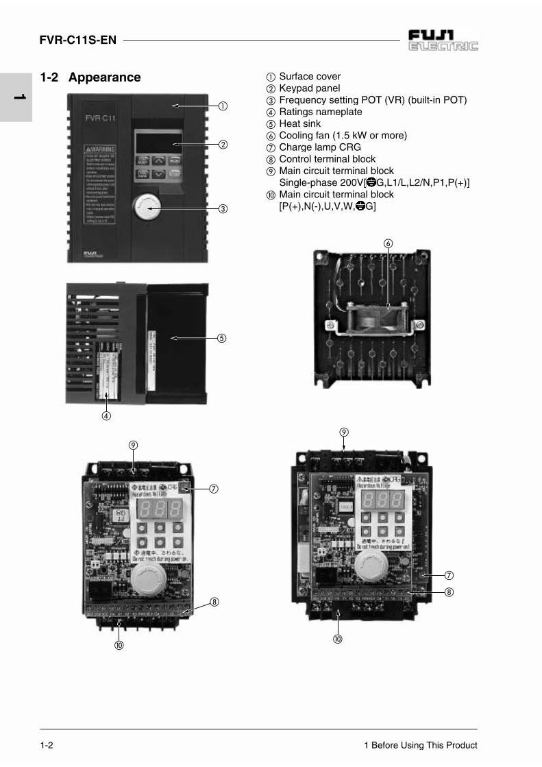
1-2 Appearance Surface cover Keypad panel Frequency setting POT (VR) (built-in POT) Ratings nameplate Heat sink Cooling fan (1.5 kW or more) Charge lamp CRG Control terminal block Main circuit terminal block
Single-phase 200V[ G,L1/L,L2/N,P1,P(+)] Main circuit terminal block
[P(+),N(-),U,V,W, G]

1 Before Using This Product 1-3
FVR-C11S-EN
1
1-3 Handling the Product
Remove the surface cover as explained below.
1) For FVR0.1 to 0.75C11S-7EN
Grasp the upper and lower parts of the coverwith both hands and pull it to the front of theinverter.
2) For FVR1.5 to 2.2C11S-7EN
Expand the lower part of the cover horizontal-ly, lift the cover to the front, and then removeit.

1-4 1 Before Using This Product
FVR-C11S-EN
1
Table 1-5-1 Storage and transportation environment
1-4 Carrying Always hold the main unit while carrying this product.If it is carried by the cover or parts and not the main unit, the productmay be damaged or dropped.Force must not be applied to the inverter cover during carrying becauseit is made of plastic.
1-5 Storage and transportation
Store and transportation this product under the conditions listed in Table 1-5-1.
Item Specifications
Storage tempera-ture Transportationtemperature
-25 to +65 °C Condensation or formation of ice must not becaused by sudden temperature changes.
Relative humidity 5 to 95% 1)
Atmosphere The product must not be exposed to dust, direct sunlight, corrosive gas, in-flammable gas, oil mist, vapor, water drops, or vibration. There must be nosalt in the atmosphere.
Air pressure 86 to 106kPa (During storage)
70 to 106kPa (During transportation)
1) A large change in temperature within this humidity range may cause condensationor formation of ice. Do not store this product at a place where such changes occur.
[Storage precautions]1. Do not locate this product directly on a floor; place it on a rack or
shelf.
2. To store the product in a severe atmosphere, pack it in vinyl sheet.
3. If the product must be stored at a place where it may be affected byhumidity, insert a drying agent such as silica gel and pack it in vinylsheet.

2 Installation and Connection 2-1
FVR-C11S-EN
2
2 Installation and Connection
Table 2-1-1 Operating environment
2-1 OperatingEnvironment
Install this product at a place satisfying the conditions listed in Table 2-1-1.
Item Specifications
Place Indoor
Ambient temperature -10 to +50 °C
Ambient relative humidity 5 to 95%RH (No condensation allowed)
Atmosphere The product must not be exposed to dust, direct sunlight, corrosivegas, inflammable gas, oil mist, vapor, or water drops.There must be no salt in the atmosphere. Condensation must notbe caused by sudden changes in temperature.
Altitude 1000 m or less (Air pressure : 86kPa to 106kPa)
Vibration 3mm: 2 ~ 9 Hz or less9.8 m/s2: 9 ~ 20 Hz or less2 m/s2: 20 ~ 55 Hz or less1 m/s2: 55 ~ 200 Hz or less

FVR-C11S-EN
2-2 2 Installation and Connection
2
2-2 Installation Method
1. Tightly fasten the product in the upright posi-tion on a strong structure using four bolts(M4) with the characters FVR-C11 facing thefront. Be sure not to turn the product upsidedown, and install it on a horizontal surface.
2. Heat is generated while the inverter is operat-ing, so the gaps shown in Figure 2-2-1 arenecessary for the passage of cooling air. Thegenerated heat is radiated upward by thebuilt-in cooling fan, so do not install this prod-uct below a device that is sensitive to heat.
Figure 2-2-1 Installation direction and surrounding space
3. The temperature of the heat sink increases toabout 90 °C while the inverter is operating.Therefore, the surface behind where theproduct is located must be able to withstandthis temperature increase.
4. When installing this product in a control pan-el, carefully consider the ventilation to pre-vent the ambient temperature of the inverterfrom exceeding the specified value. Do notinstall it in a hermetically sealed box fromwhich heat is not radiated fully.
5. If two or more inverters need to be installed inthe same device or control panel, they shouldbe arranged horizontally to minimize the influ-ence of heat between them. If two or more in-verters must be installed vertically, place aplate between them to prevent the upper in-verter from being affected by heat from thelower inverter.
a) Horizontal arrangement
b) Vertical arrangement
Figure 2-2-2 How to install two or more inverters
10cm
1cm FVR-C11 1cm
10cm
WARNINGInstall this product on a nonflammable material such as metal.Otherwise fire could occur.
Inverter Inverter
Air supply Air supply
Airsupply
Inverter
Plate
Inverter

2 Installation and Connection 2-3
FVR-C11S-EN
2
2-3 Connection
Remove the surface cover to connect the termi-nal blocks. Correctly connect them according tothe following procedures.
2-3-1 Basic connection1. Always connect the power to the main power
supply input terminal of the inverter. If it isconnected to another terminal, the inverterwill be damaged (see Figure 2-3-1).
2. Always ground the ground terminal to preventdisasters such as fire and electric shock andto minimize noise.
3. Use a reliable crimp terminal for connectionbetween a terminal and wire.
4. After terminating the connection (wiring),check the following items:a. Whether the connection is correctb. Whether all necessary connections have
been madec. Whether there is a short-circuit or ground
fault between terminals and wires
5. Connection modification after power-onThe smoothing capacitor in the direct currentpart of the main circuit cannot be dischargedquickly after the power is turned off. Use amultimeter to check that the voltage of the di-rect current (DC) is reduced to the safetyrange (25V DC or less) after the charge lampgoes off to avoid danger. Check that the volt-age is zero before short-circuiting a circuit be-cause the residual voltage (electric charge)may cause sparks.
CAUTIONDo not allow foreign matter such aslint, paper dust, small chips of wood ormetal, and dust to enter the inverter oradhere to the heat sink.Otherwise, a disaster such as burningcould occur.
WARNING
1. Always connect the ground wire.Otherwise electric shock and fire couldoccur.
2. Ensure that a licensed specialist performsthe wiring work.
3. Check before starting the wiring that thepower is off.Otherwise electric shock could occur.
2-4 2 Installation and Connection
FVR-C11S-EN
2
2-3-2 Connecting the main circuit and ground terminals
Table 2-3-1 Functions of main circuit and ground terminals
Symbol Name Explanation
L1/L,L2/N Main power supply input Connects single-phase power(Single-phase 200V input).
U, V, W Inverter output Connects 3-phase motor.
P1, P(+) For connection of DC reactor
Connects input power- factor correcting DC reactor(optional).
P(+), N(-) For DC intermediate circuit
Connected to DC link circuit terminal(for DC bus connection).
G For inverter grounding Ground terminal for inverter chassis (case).
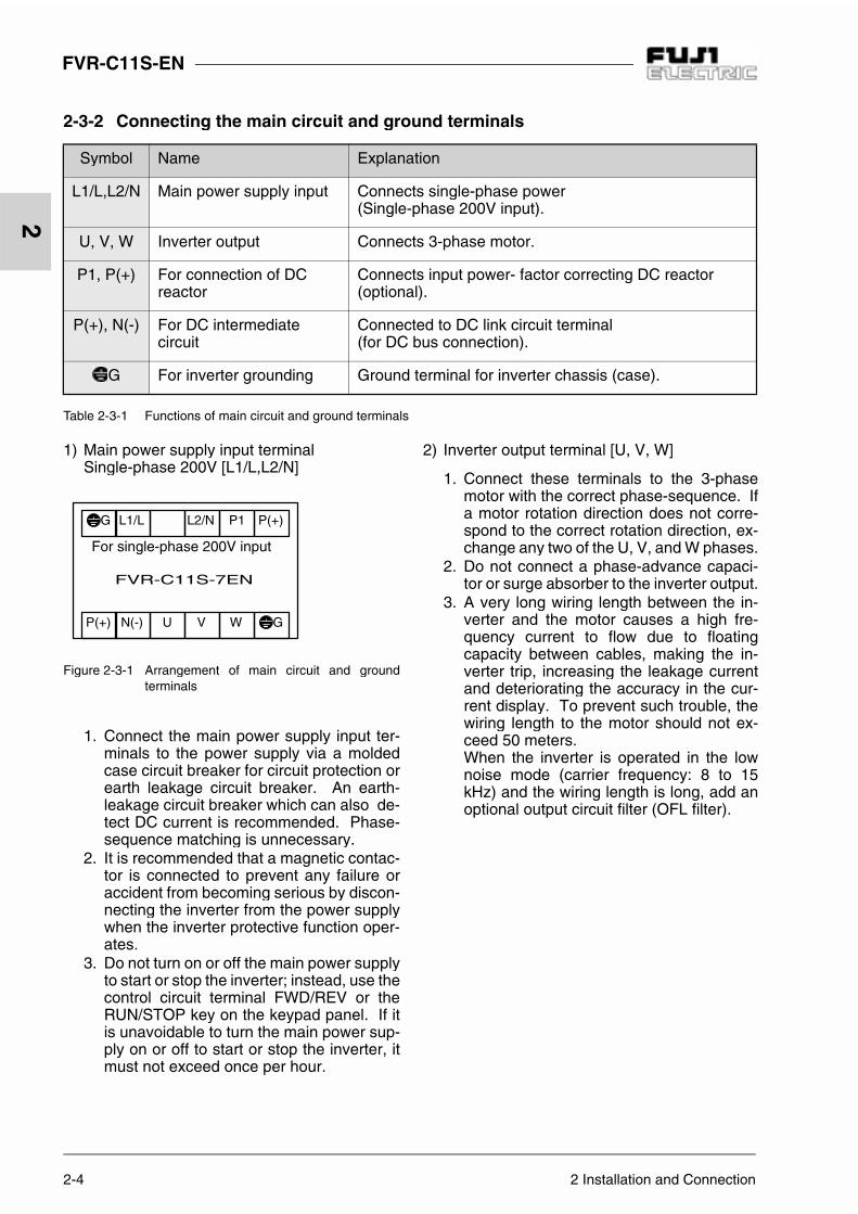
1) Main power supply input terminalSingle-phase 200V [L1/L,L2/N]
Figure 2-3-1 Arrangement of main circuit and groundterminals
1. Connect the main power supply input ter-minals to the power supply via a moldedcase circuit breaker for circuit protection orearth leakage circuit breaker. An earth-leakage circuit breaker which can also de-tect DC current is recommended. Phase-sequence matching is unnecessary.
2. It is recommended that a magnetic contac-tor is connected to prevent any failure oraccident from becoming serious by discon-necting the inverter from the power supplywhen the inverter protective function oper-ates.
3. Do not turn on or off the main power supplyto start or stop the inverter; instead, use thecontrol circuit terminal FWD/REV or theRUN/STOP key on the keypad panel. If itis unavoidable to turn the main power sup-ply on or off to start or stop the inverter, itmust not exceed once per hour.
2) Inverter output terminal [U, V, W]
1. Connect these terminals to the 3-phasemotor with the correct phase-sequence. Ifa motor rotation direction does not corre-spond to the correct rotation direction, ex-change any two of the U, V, and W phases.
2. Do not connect a phase-advance capaci-tor or surge absorber to the inverter output.
3. A very long wiring length between the in-verter and the motor causes a high fre-quency current to flow due to floatingcapacity between cables, making the in-verter trip, increasing the leakage currentand deteriorating the accuracy in the cur-rent display. To prevent such trouble, thewiring length to the motor should not ex-ceed 50 meters.When the inverter is operated in the lownoise mode (carrier frequency: 8 to 15kHz) and the wiring length is long, add anoptional output circuit filter (OFL filter).
GWVUN(-)P(+)
FVR-C11S-7EN
P(+)P1L2/NG L1/L
For single-phase 200V input

2 Installation and Connection 2-5
FVR-C11S-EN
2
3) DC reactor connecting terminal [P1, P(+)]
1. Use this terminal to connect a input power-factor correcting DC reactor (optional).Remove the jumper connected in the fac-tory before connecting the DC reactor (seeFigure 2-3-2).
a) Connection diagram
b) Cutting of barrier
Figure 2-3-2 Connection of DC reactor
2. Use diagonal cutting pliers to cut the sur-face cover barriers from P1, P(+) terminalsbefore connection.
3. If no DC reactor is used, do not remove thejumper.
4) Inverter grounding terminal [ G]Always ground the inverter grounding termi-nal [ G] for safety and noise reduction.Grounding of the metal frames of electricequipment has to be done in accordance withthe national and local safety specifications inforce.
1. In Japan, the 200V system must be con-nected to a ground electrode provided withclass D grounding, according to the electri-cal equipment technical standard.
Table 2-3-2 Grounding of device according toelectrical equipment technical standard
2. Connect a thick and short wire to thegrounding terminal of the inverter for con-nection with a ground electrode preparedexclusively for the inverter system.
P(+)P1
FVR-C11S-7EN
Top of inverter
Barrier
Voltagesystem
Type of ground-ing work
Groundingresistance
200VClass D grounding
100 Ωmaximum
CAUTION
1. Check that the number of phases and therated voltage of this product correspondto the number of phases and voltage of theAC power supply.Otherwise fire could occur.
2. Do not connect the AC power supply to theoutput terminals (U, V, W).Otherwise injury could occur.
3. Do not connect a braking resistor directly tothe DC terminals P(+), N(-).Otherwise fire could occur.

FVR-C11S-EN
2-6 2 Installation and Connection
2
2-3-3 Connecting the control terminalsTable 2-3-4 lists the functions of the control cir-cuit terminals.The method of connecting a control circuit termi-nal depends on how its function is set.Connect the control circuit terminals accordingto the set functions.
1) Digital input terminalFigure 2-3-3 shows the circuit configuration.Use a reliable contact without poor contact forinput.Example: FUJI control relay HH54PW
a) When SW7 is set to CM (factory setting)
b) When SW7 is set at P24
Figure 2-3-3 Digital input terminal
2) Run/stop command terminal [FWD, REV]These terminals are left open in the factory.Pressing the key on the keypad panelstarts forward operation. When function F02is set at 0 or 1, the terminal functions are asshown in Table 2-3-3.
SW7
P24
F1
0 V
P24/CM
CM
4.7k
FVR-C11S-7EN
+24 to
+27VDC
+24 to +27VDC
FWD or others
SW7
P24
F1
0 V
40mA max.
P24/CM
CM
4.7k
FVR-C11S-7EN
FWD or others
+24 to +27VDC

2 Installation and Connection 2-7
FVR-C11S-EN
2
Table 2-3-3 Description of function F02
F02 When SW7 is set at CM When SW7 is set at P24
0
When +24 to +27 VDC is supplied to FWD - P24/CM, pressing the key on the keypad panel starts forward operation.When +24 to +27 VDC is supplied to REV - P24/CM, pressing the key on the keypad panel starts reverse operation. When +24 to +27 VDC is supplied to both FWD - P24/CM and REV - P24/CM, the inverter decelerates to stop.
When FWD is short-circuited to P24/CM and thekey on the keypad panel is pressed, for-
ward operation starts. When REV is short-circuited to P24/CM and the
key on the keypad panel is pressed, re-verse operation starts.When both FWD - P24/CM and REV - P24/CM are short-circuited, the inverter decelerates to stop.
1
When +24 to +27 VDC is supplied to FWD - P24/CM, forward operation starts. When +24 to +27 VDC is supplied to REV - P24/CM, reverse operation starts. When +24 to +27 VDC is supplied to both FWD - P24/CM and REV - P24/CM, the inverter decelerates to stop.
Short-circuit FWD to P24/CM for forward opera-tion, or REV to P24/CM for reverse operation. Short-circuiting both FWD - P24/CM and REV - P24/CM brings the inverter to deceleration and stop.
3) Analog input terminal (13, 12, 11, C1)Use these terminals to connect external inputanalog voltage and analog current and fre-quency setting device (POT). For connectinga contact to this circuit, use a twin contact forfine current signal.Do not use a contact for terminal 11.
CAUTIONIn case P24 is short-circuited with 0Vby outer circuit when SW7 is set to P24side, poly switch (F1) turns the poweroff. To recover the power, open theshort circuit and turn the inverter off toallow the temperature to lower.
WARNINGThe STOP key is valid only when thefunction has been set. Prepareanother switch for emergency stop.When operation using an external si-gnal terminal is selected, the operationcannot be stopped using the STOPkey on the keypad panel.Otherwise accidents could occur.

FVR-C11S-EN
2-8 2 Installation and Connection
2
*Note the following when wiring:
1) Surge absorber connectionWhen the exciting coil of the magnetic con-tactor or relay in the control circuit or inverterperipheral circuit is opened or closed, a surgevoltage (noise) is generated with a suddencurrent change. Due to this surge voltage,the inverter control circuit or peripheral equip-ment may malfunction. If so, directly connecta surge absorber to both ends of the coil.(See Figure 2-3-4).
Figure 2-3-4 Surge absorber connection diagram
2) Control circuit wiring
1. Wires connected to control circuit termi-nals must be 0.5mm2 shielded wire ortwisted vinyl wire. Remove the sheath asshown in Figure 2-3-5 and then connect it.
Figure 2-3-5 End treatment
2. Keep the wiring of the main circuit, exter-nal relay sequence circuit and control cir-cuit as far away from each other aspossible. If they must be adjacent, crossthem at right angles.
3. Use a twisted-pair shielded wire for longwiring distances.
3) Shielding sheath connectionConnect one end of the shielding sheath of ashielded or twisted-pair shielded wire to theground terminal as shown in Figure 2-3-6. Donot connect the other end.
Figure 2-3-6 Connection of sheath of shielded wire
+
-
Ry DMC
SK
SK: Surge absorber D: Diode
AC relay DC relay
6 ±1mm
P24/CM
131211
FWD
ContactShield
Shield
Frequencysetting POT
To ground terminal
To ground terminal
CAUTIONNoise is generated from the inverter,motor, and wiring. Take care that thisnoise does not cause malfunctions inperipheral sensors and equipment.Otherwise accidents could occur.

2 Installation and Connection 2-9
FVR-C11S-EN
2
Figure 2-3-7 Control terminal block arrangement
Figure 2-3-8 How to pull out the control wiring
4) Control terminal arrangement, screw size,and tightening torque.
Figure 2-3-7 shows the control terminal blockarrangement.
Screw size: M2.5Tightening torque: 0.4 Nm
5) Remove the plate at the bottom of the surfacecover before performing inverter control wir-ing and reinstall it after the wiring as shown inFigure 2-3-8.
30A 30B 30C FM X1 X2 X3 FWD REVP24/CM
11 12 13 C1
PlateControl wiring

2-10 2 Installation and Connection
FVR-C11S-EN
2
Classifi-cation
Terminalsymbol Terminal name Detailed specifications Remarks
Analoginput
13 Power supply forvariable resistor
Used as power supply for frequencysetting device (POT: 1 to 5 kΩ).(+10VDC 10mADC max.)
12 Frequency settingvoltage input
0 to +10VDC/0 to 100%,0 to +5VDC/0to 100% (Input impedance : 22 kΩ)
C1 Frequency settingcurrent input
4 to 20mADC/0 to 100% (Input impedance : 250 Ω)
11 Analog common Common terminal for analog input signals
Digitalinput
FWD Forward operation/Stop command
Forward operation with FWD-P24/CM ON and deceleration-stop with FWD-P24/CM OFF(Switch SW7 to P24)
Decelera-tion-stopwithFWD-P24/CM and REV-P24/CM ONREV
Reverseoperation/Stop command
Reverse operation with REV-P24/CM ON and deceleration-stop with REV-P24/CM OFF(Switch SW7 to P24)
X1 Digital input 1 The functions listed below can be setby the X1 to X3 terminal functions. Set with
functionsE01 to E03
X2 Digital input 2
X3 Digital input 3
(SS1)(SS2)
Multistepfrequencyselection
Up to four steps speed operation canbe selected with SS1 and SS2 ON/OFF signals.
(BX) Coast to stop command
Inverter output is cut immediately andthe motor coasts to a stop (no alarmoutput) if BX goes on.
(RST) Alarm reset The inverter releases the status held
after stop with an alarm when RSTchanges from ON to OFF.
(THR) External alarm input
The inverter stops with an alarm ifTHR is set to OFF.
(WE-KP)
Write-enable com-mand for keypad(data change al-lowed)
Data rewriting for each function withthe keypad panel is rejected if WE-KPis OFF.
Rewriting with keypad panel is allowed if WE-KP is ON.

2 Installation and Connection 2-11
FVR-C11S-EN
2
Table 2-3-4 Functions of control circuit terminals
Classifi-cation
Terminalsymbol Terminal name Detailed specifications Remarks
Digitalinput
(Hz/PID) PID control cancel PID control cancel with Hz/PID ON PID control with Hz/PID OFF
(LE) Link operation selection
Operation based on command fromRS485 with LE ON
Inverter single operation with LE OFF
Output/Input P24/CM Power Supply/
Digital Common
DC Power supply (SW7 set to P24)(+24 to +27 VDC, 40mA max.)
Common terminal for digital input signal (SW7 set to CM) (factory set-ting)
Switching ofP24/CM ter-minal withswitch SW7
Analogoutput FM, 11 Analog monitor
Data selected between the followingitems is output with DC voltage: Output frequency PID feedback value Output current DC link circuit voltage* Up to two analog voltmeters (input impedance : 10 kΩ) can be connected.Note: Output waveform: An AC pulse
is output with consistent frequen-cy and variable duty.The average DC voltage is pro-portional to output frequency andoutput current (frequency : 121.6 Hz).
Contactoutput
30A30B30C
Alarm output forany fault
If the inverter is stopped with an alarm,the non-voltage contact signal (1SPDT)is output(Contact rating: 250V AC, 0.3 A, Powerfactor = 0.3)(48V DC, 0.5A for Low-voltage Directiveor 42V DC, 0.5A for UL/cUL)* Whether an alarm is generated with anexciting operation or non-exciting opera-tion can be switched.
OptionalDX+DX-
RS485 communi-cation input/output
Terminal for RS485 communication(when option board is installed)
DX+ : Non-inverted signal, DX- : Inverted signal
Installedon optionalboard.

2-12 2 Installation and Connection
FVR-C11S-EN
2
Figure 2-3-9 Wiring diagram of keypad panel operation
2-3-4 Connection examples1) Keypad panel operation
12
V
U
W
13
FWD
11
X1
REV
P24
SW7CM
P24/CM
X3
30C
30B
30A
X2
L1/L
L2/N
P1 N(-)
M
FM
C1
MCCB
2)
STOP
RUNPRGRESET
FUNCDATA
250
22k
0V
P1 P(+)
E
CM
P24SW7
G G
4.7k
P(+) P(+)
3
0V
F1
+10VDC
When power-factor correctingDC reactor is used
Single-phase200V input series200 to 240V 50/60Hz
Frequency setting POT (VR)
Pulse output Analog monitor
Alarm output for any fault
+24 to +27 VDC

2 Installation and Connection 2-13
FVR-C11S-EN
2
1) The RUN and STOP keys on the keypad pan-el can be used to start and stop the operationand the frequency setting POT (VR) can beused to set a frequency only by connectingthe power supply and motor with functions setin the factory. Forward rotation is set in thefactory.
2) Remove the jumper between the P1 and P(+)terminals before connecting the optional pow-er-factor correcting DC reactor.
3) Connect the surge absorber in parallel to coils(such as coils of the magnetic contactor andsolenoid) near the inverter.

2-14 2 Installation and Connection
FVR-C11S-EN
2
Figure 2-3-10 Wiring diagram of external operation (When external power supply is used)
2) External operation (When external power supply is used)
12
V
U
W
13
11
30C
30B
30A
P1 P(+) N(-)P(+)
M
FM
C1
P1 P(+)
E
3)
+10VDC
250Ω
22k
0V
GG
STOP
RUNPRGRESET
FUNCDATA
3
L1/L
L2/N
MCCB
FWD
SW7CM
CM
P24SW7
4.7kΩ
REV
F1
X1
X2
X3
P24/CM
P24
0V
To ground terminal
Single-phase200V input series200 to 240V 50/60Hz
+24 to +27 VDC
When power-factor correctingDC reactor is used
Frequency setting POT (VR)
Pulse output
Analogmeter
Alarm output for any fault
Analogmonitor
To ground terminal
To 11 terminal
Frequency settingvoltage input (0 to +10VDC)
Frequency settingcurrent input (4 to +20mADC)
Forwardoperation command
Reverse operation command
24VDC
2 Installation and Connection 2-15
FVR-C11S-EN
2
1) Use this connection to start, stop the opera-tion and set the frequency with external sig-nals. 0 to 10V DC can be set while functionF01 is set to 1 and +4 to +20mA DC can beset while function F01 is set to 2. Set functionF02 to 1.
2) Set SW7 at CM
3) Remove the jumper between the P1 and P(+)terminals before connecting the optional pow-er-factor correcting DC reactor.
4) Connect the surge absorber in parallel to coils(such as coils of the magnetic contactor andsolenoid) near the inverter.
5) Use twisted or shielded wire as control signalwire. Connect the shield to the ground termi-nal.
2-16 2 Installation and Connection
FVR-C11S-EN
2
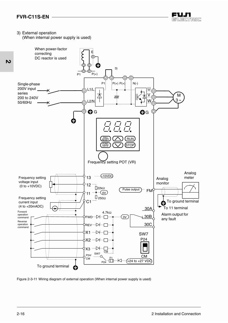
Figure 2-3-11 Wiring diagram of external operation (When internal power supply is used)
3) External operation(When internal power supply is used)
12
V
U
W
13
11
30C
30B
30A
P1 P(+) N(-)P(+)
M
FM
C1
P1 P(+)
E
3)
+10VDC
250
22k
0V
GG
STOP
RUNPRGRESET
FUNCDATA
3
L1/L
L2/N
FWD
SW7CM
CM
P24SW7
4.7k
REV
X1
X2
X3
P24/CM
P24
0V
F1
To ground terminal
Single-phase200V input series200 to 240V 50/60Hz
+24 to +27 VDC
When power-factor correctingDC reactor is used
Frequency setting POT (VR)
Pulse output
Analogmeter
Alarm output for any fault
Analogmonitor
To ground terminal
To 11 terminal
Frequency settingvoltage input (0 to +10VDC)
Frequency settingcurrent input (4 to +20mADC)
Forwardoperation command
Reverse operation command

2 Installation and Connection 2-17
FVR-C11S-EN
2
1) Use this connection to start, stop the opera-tion and set the frequency with external sig-nals. 0 to 10V DC can be set while functionF01 is set to 1 and +4 to +20mA DC can beset while function F01 is set to 2. Set functionF02 to 1.
2) Set SW7 at P24.
3) Remove the jumper between the P1 and P(+)terminals before connecting the optional pow-er-factor correcting DC reactor.
4) Connect the surge absorber in parallel to coils(such as coils of the magnetic contactor andsolenoid) near the inverter.
5) Use twisted or shielded wire as control signalwire. Connect the shield to the ground termi-nal.

2-18 2 Installation and Connection
FVR-C11S-EN
2
Figure 2-3-12 Connection example of PLC terminal (using THR function terminal)
4) Connection to PLC (When external thermal O/L relay is used)
12
V
U
W
13
FWD
11
X1
X2
REV
P24/CM
X3
30C
30B
30A
L1/L
L2/N
P1 P(+) N(-)P(+)
M
FM
+10VDC
0V
0V
DC24V
P24
CM
SW7
G G
250
22k
CMSW7
STOP
RUNPRGRESET
FUNCDATA
3
F1
P24
(THR)
4.7k
C1
To ground terminal
Frequency setting POT (VR)
MCCB
Pulse output
External thermal O/L relay
To X3 terminal
Tooutputterminalof PLC
External thermal O/L relayDC24V :
PLC power supply
PLC
Single-phase200V input series200 to 240V 50/60Hz
+24 to +27 VDC
Analogmeter
Alarm output for any fault
Analogmonitor
To groundterminal
To 11 terminal

2 Installation and Connection 2-19
FVR-C11S-EN
2
1) Set SW7 at CM.
2) In the figure above, the power is supplied tothe external thermal relay from the powersupply of the PLC. If the power supply of thePLC is turned off while the inverter remainsturned on, OH2 trips.
3) To prevent OH2 from tripping upon shutdownof the PLC, deselect the THR terminal func-tion and use the electronic relay of the invert-er.
CAUTIONWhen SW7 is set at P24, possiblycausing inner parts to damage.

2-20 2 Installation and Connection
FVR-C11S-EN
2
Figure 2-3-13 Connection example of PLC terminal (when analog signal is input from PLC)
1) Set SW7 at CM.2) With this connection, the power is supplied from the PLC power supply to the external thermal O/L relay.
So, OH2 trip is activated by PLC power-off with the inverter turned on.3) To prevent inverter trip with OH2 when the PLC power being turned off, do not select the THR terminal function and
use the inverter electronic thermal O/L relay.
5) Connection to PLC (When analog signal is input from PLC)
When SW7 is set at P24, poly switch (F1) activates a current limit toturn the power off.
12
V
U
W
13
11
30C
30B
30A
P1 P(+) N(-)P(+)
M
FM
C1
+10VDC
250
22k
0V
GG
DC24V
STOP
RUNPRG
RESET
FUNCDATA
3
L1/L
L2/N
FWD
X1
X2
REV
P24/CM
X3
0V
P24
CM
SW7
CMSW7
F1
4.7k
P24
(THR)
Frequency setting POT (VR)
MCCBExternal thermal relay
To X3 terminal
Tooutputterminalof PLC
Single-phase200V input series200 to 240V 50/60Hz
+24 to +27 VDC
To ground terminal
Pulse output
ExternalthermalO/L relay
DC24V : PLC power supply
PLC
Analogmeter
Alarm output for any fault
Analogmonitor
To groundterminal
To 11 terminal
CAUTION
2 Installation and Connection 2-21
FVR-C11S-EN
2
2-4 Others
2-4-1 Harmonic componentA harmonic component which may influence thephase-advance capacitor and generator is in-cluded in the inverter input current. If necessary,connect a power-factor correcting DC reactor(DCR) (option) for the inverter.
2-4-2 NoiseWhen noise generated from the inverter may af-fect peripheral equipment, and noise generatedfrom peripheral equipment may malfunction theinverter, the following basic countermeasuresshould be taken.
1) When noise affects other devices via powerand ground wires
Separate the ground of the inverter andthat of the affected device.
Connect a noise filter to the inverter powerwire.
Use an isolation transformer to separatethe power supply of the inverter and that ofthe affected device.
2) When another device is affected by inductionor radiation
Separate the main circuit wiring of the in-verter from the control wiring and wiring ofthe affected device.
Encase the inverter main circuit wiring in ametal tube and ground the metal tube nearthe inverter.
Encase the inverter in a metal rack andground the rack.
Connect a noise filter to the inverter powerwire.
3) When noise generated from peripheral equip-ment affects the inverter
Use twisted or twisted-pair shielded wiresfor the inverter control wiring. Ground theshields.
Connect a surge absorber in parallel to thecoil of the magnetic contactor and sole-noid.
If the power supply includes much distor-tion of the waveform or surge, connect animpedance matching AC reactor for coor-dination of power supply.
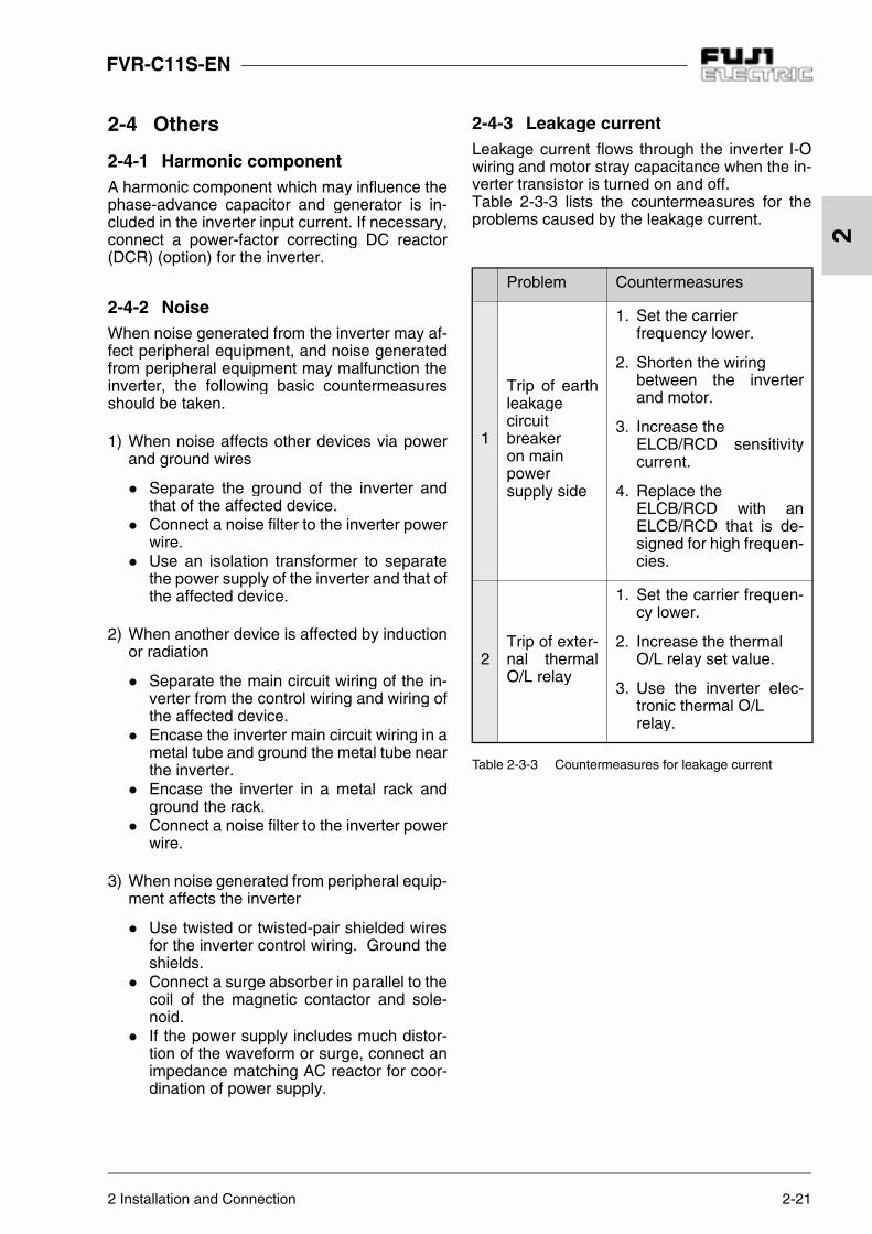
2-4-3 Leakage currentLeakage current flows through the inverter I-Owiring and motor stray capacitance when the in-verter transistor is turned on and off.Table 2-3-3 lists the countermeasures for theproblems caused by the leakage current.
Table 2-3-3 Countermeasures for leakage current
Problem Countermeasures
1
Trip of earthleakagecircuitbreakeron mainpowersupply side
1. Set the carrier frequency lower.
2. Shorten the wiringbetween the inverterand motor.
3. Increase the ELCB/RCD sensitivitycurrent.
4. Replace the ELCB/RCD with anELCB/RCD that is de-signed for high frequen-cies.
2Trip of exter-nal thermalO/L relay
1. Set the carrier frequen-cy lower.
2. Increase the thermal O/L relay set value.
3. Use the inverter elec-tronic thermal O/L relay.
3-1 3 Operation
FVR-C11S-EN
3
3 Operation
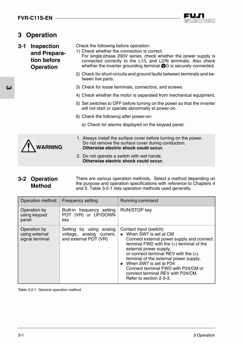
Table 3-2-1 General operation method
3-1 Inspection and Prepara-tion before Operation
Check the following before operation:1) Check whether the connection is correct.
For single-phase 200V series, check whether the power supply isconnected correctly to the L1/L and L2/N terminals. Also checkwhether the inverter grounding terminal G is securely connected.
2) Check for short-circuits and ground faults between terminals and be-tween live parts.
3) Check for loose terminals, connectors, and screws.
4) Check whether the motor is separated from mechanical equipment.
5) Set switches to OFF before turning on the power so that the inverterwill not start or operate abnormally at power-on.
6) Check the following after power-on:
a) Check for alarms displayed on the keypad panel.
1. Always install the surface cover before turning on the power.Do not remove the surface cover during conduction.Otherwise electric shock could occur.
2. Do not operate a switch with wet hands.Otherwise electric shock could occur.
3-2 Operation Method
There are various operation methods. Select a method depending onthe purpose and operation specifications with reference to Chapters 4and 5. Table 3-2-1 lists operation methods used generally.
Operation method Frequency setting Running command
Operation byusing keypadpanel
Built-in frequency settingPOT (VR) or UP/DOWNkey
RUN/STOP key
Operation byusing external signal terminal
Setting by using analogvoltage, analog current,and external POT (VR)
Contact input (switch) When SW7 is set at CM
Connect external power supply and connectterminal FWD with the (+) terminal of the external power supply,or connect terminal REV with the (+) terminal of the external power supply.
When SW7 is set at P24Connect terminal FWD with P24/CM or connect terminal REV with P24/CM.Refer to section 2-3-3.
WARNING

3 Operation 3-2
FVR-C11S-EN
3
Table 3-3-1 Running command
3-3 Trial Run The motor rotates when a frequency value and running command areinput from the keypad panel or external signal terminal.Refer to Table 3-3-1.Use a low frequency (about 5Hz) for trial runs.A frequency can be set using the built-in frequency setting POT (VR) ,and forward/stop can be performed using the keypad panel with thefunctions set in the factory.
Operation method Frequency setting Running command
Operation byusing keypadpanel
(When built-in POT (VR) is used)The frequency increases whenthe variable resistor is turnedclockwise and reduces when it isturned counterclockwise.The motor accelerates when thevariable resistor is turned clock-wise during operation and decel-erates when it is turnedcounterclockwise.
(When the UP/DOWN key isused)Frequency increases when theUP key is pressed.It reduces when the DOWN keyis pressed.
Operation starts when the RUN key ispressed.The motor decelerates and stops whenthe STOP key is pressed.
Operation byusing external signal terminal
When SW7 is set at CMConnect external power supply andturn FWD (REV) on to start. Turn it offto bring the inverter to decelerationand stop.
When SW7 is set at P24 Turn FWD (REV) on to start. Turn it offto bring the inverter to decelerationand stop.
Operation is not stopped although theSTOP key is pressed. Refer to section 2-3-3.
FVR-C11S-EN
3-3 3 Operation
3
Check the following items:a) Rotation directionb) Whether rotation is smooth (whether there
is a motor buzzing noise or abnormal vi-bration)
c) Whether acceleration and deceleration aresmooth
d) Whether the inverter cooling fan is rotating(1.5kW or more)
If no abnormality is detected, check the itemagain by increasing the frequency.Even if the output from the inverter is stopped,you will be get an electric shock when you touchthe main circuit terminals such as inverter outputterminals U, V and W if the voltage is supplied tothe main power supply input terminal.The smoothing capacitor in the inverter hasbeen charged when the power is turned off andit is not discharged immediately. Before touch-ing the electric circuit, wait until at least five min-utes have elapsed after power-off and thecharge lamp is off, indicating the voltage is al-ready low.After checking normality in the above trial run,start operation.
WARNING
1. The STOP key is valid only when the func-tion has been set.Assign another switch to emergency stops.Otherwise accidents could occur.
2. Operation starts suddenly if alarm reset isdone with an running signal input. Checkthat no running signal is input before alarmreset.Otherwise accidents could occur.
CAUTION
Do not touch the heat sink.Otherwise burns could occur.

4 Keypad Panel 4-1
FVR-C11S-EN
4
4 Keypad Panel
4-1 Names and Functions
Digital displayIn program mode: Shows function codes and data codes.In Operation mode: Shows the output frequencyand output current, etc.In Trip mode: Shows a code indicating the causes of the trip.
Program (Reset) keySwitches between Operation mode and Programmode.In Trip mode: Resets the trip status and changeto Operation mode.
Function/Data keyIn Operation mode: Switches between frequencydisplay and output current display during stopped and running. In Program mode: Used to read and write various function codes and function data items.
Up/down keysIn Operation mode: Used to increase and reduce the frequency (motor speed).In Program mode:Used to change a function code and data value.
RUN keyThis key is used to start operation.The LED is on during operation.This key does not function when the data code from the external signal (digital input) is selected (F02 = 1).
STOP keyThis key is used to stop operation.This key does not function when the data code from the external signal (digital input) is selected (F02 = 1).
4-2 Operating Keypad Panel
1) Switching monitorThe display can be switched between fre-quency display and output current display by
pressing the in Operation mode.
1) Frequency is displayed as a percentage with the leastsignificant digit in PID control operation (function H20is set to 1 or 2):
for 10%
for 100%
2) The reference frequency is displayed when thekey is pressed in current indication.
2) Stopping operation
Operation is started when the is
pressed, and is stopped when the is
pressed while function is set to a val-
ue other than .
The rotation direction is:
= : Forward rotation withFWD-P24/CM ON, andreverse rotation withREV-P24/CM ON
= : Forward rotation (FWD/REV input is ig-nored.)
= : Reverse rotation (FWD/REV input is ig-nored.)
6 0. 0 1. 2 A
1 0. 0.
1 0 0.
F 0 2
1
F 0 2 0
F 0 2 2
F 0 2 3
Frequency 1) Current 2)
4-2 4 Keypad Panel
FVR-C11S-EN
4
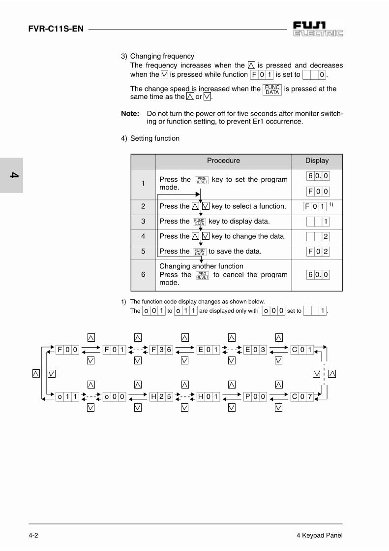
3) Changing frequencyThe frequency increases when the is pressed and decreaseswhen the is pressed while function is set to .
The change speed is increased when the is pressed at thesame time as the or .
Note: Do not turn the power off for five seconds after monitor switch-ing or function setting, to prevent Er1 occurrence.
4) Setting function
Procedure Display
1 Press the key to set the programmode.
2 Press the key to select a function. 1)
3 Press the key to display data.
4 Press the key to change the data.
5 Press the to save the data.
6Changing another functionPress the to cancel the programmode.
1) The function code display changes as shown below.
The to are displayed only with set to .
F 0 1 0
6 0. 0
F 0 0
F 0 1
1
2
F 0 2
6 0. 0
o 0 1 o 1 1 o 0 0 1
F 0 0 F 0 1 F 3 6 E 0 1 E 0 3 C 0 1
o 1 1 o 0 0 H 2 5 H 0 1 P 0 0 C 0 7

5 Selecting Function 5-1
FVR-C11S-EN
5
Change during operation: X = impossible, = possible (enabled by using ), = possible (enabled by using )
5 Selecting Function
5-1 Function Selection List
F: Fundamental functions
Func-tioncodeNo.
Name Setting range UnitMin.unit
Factorysetting
Changeduringopera-
tion
Userset-ting
F00 Data protection0: Data change enabled,1: Data protected
- - 0 X
F01Frequencycommand
0: Key operation ( , key)1: Voltage input (terminal [12])
(0 to +10VDC)2: Current input (terminal[C1])
(4 to 20mADC)3: Voltage input + current input
(terminals[12]+[C1])4: Analog (VR built in inverter)
- - 4 X
F02Operationmethod
0: Key operation(rotation direction: By terminal block)
1: External signal (digital input)2: Key operation
(forward rotation)3: Key operation
(reverse rotation)
- - 2 X
F03Maximum out-put frequency
50 to 120Hz Hz 1 50 X
F04 Base frequency 25 to 120Hz Hz 1 50 X
F05- Data cannot be changed. - -
0-
F06 0
F07Accelerationtime
0.0 to 60.0s0.01 second is set when 0.0 is specified.
s 0.1 6.0
F08Decelerationtime
0.1 to 60.0s s 0.1 6.0
F09 Torque boost0,1 : Variable torque characteristic2 to 31: Constant torque characteristic
- 1 13

5-2 5 Selecting Function
FVR-C11S-EN
5
Change during operation: X = impossible, = possible (enabled by using ), = possible (enabled by using )
Functioncode No.
Name Setting range UnitMin.unit
Factorysetting
Changeduringopera-
tion
Usersetting
F10
Electronicthermal overload relay for motor
(Select)
0: Inactive1: Active (for 4-pole standard motor)2: Active (for 4-pole FUJI inverter motor)
- - 1
F11 (Level) 20 to 135% of inverter rated current A 0.01
Typicalvalue of
FUJI4-polemotor
F12(Thermaltimeconstant)
0.5 to 10.0min min 0.1 5.0
F14Restart after mo-mentary power failure (Select)
0: Inactive (Trip and alarm when power fail-ure occurs)
1: Inactive (Trip and alarm when power re-covers)
2: Active (Momentarily stops and restarts at setting frequency of before power failure)
3: Active (Momentarily stops and restarts at starting frequency)
- - 0 X
F15Frequencylimiter
(High)0 to 120Hz
Hz 170
F16 (Low) 0 to 120Hz 0
F17Gain(for frequencysetting signal)
0: For 0 to 10VDC (4 to 20 mA DC)1: For 0 to 5VDC (4 to 12 mA DC)
- - 0 X
F18 Bias frequency -120 to 120Hz Hz 1 0
F20DC injection brake
(Startingfreq.)
Fixed to 3Hz Hz - 3.0 -
F21 (Level) 0 to 100% % 1 50
F22(Brakingtime)
0.0 s (Inactive), 0.1 to 30.0 s s 0.1 0.0
F23Startingfrequency
1 to 6Hz Hz 1 1 X
F24 - Data cannot be changed. - - 0.0 -
F25 Stop frequency 1 to 6Hz Hz 1 1 X

5 Selecting Function 5-3
FVR-C11S-EN
5
Change during operation: X = impossible, = possible (enabled by using ), = possible (enabled by using )
Func-tioncodeNo.
Name Setting range UnitMin.unit
Factorysetting
Changeduringopera-
tion
Userset-ting
F26Motor sound
(carrier freq.)0 to 15kHz0.75kHz is set when 0 is specified
kHz 1 15
F27 (sound tone )0: Level 0 1: Level 12: Level 2 3: Level 3
- - 0
F30FM terminal
(Voltageadjust)
0 to 200% % 1 100
F31 (Function)
0: Output frequency1: Output current2: PID feedback amount3: DC link circuit voltage
- - 0
F3630Ry operation mode
0: Excited when tripped1: Normally excited
- - 0 X
E: Extension Terminal Functions
Func-tioncodeNo.
Name Setting range UnitMin.unit
Factorysetting
Changeduringopera-
tion
Userset-ting
E01 X1 terminal (functionselection)
X2 terminal (functionselection)
X3 terminal (functionselection)
Use the code values listed below to select [X1], [X2] and [X3] terminal functions.
- - 0 X
E02 - - 2 X
E03 - - 3 X
0: Multistep frequency 1 (SS1)1: Multistep frequency 2 (SS2)2: Coast-to-stop command (BX)3: Alarm reset (RST)4: External alarm (THR)5: Write enable command for keypad
(WE-KP)6: PID control cancel (Hz/PID)7: Link operation selection (LE)
5-4 5 Selecting Function
FVR-C11S-EN
5
Change during operation: X = impossible, = possible (enabled by using ), = possible (enabled by using )
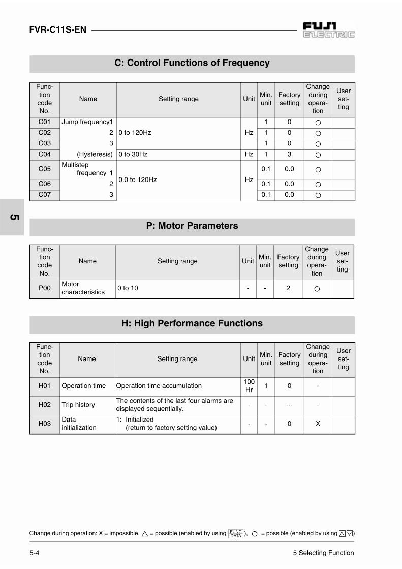
C: Control Functions of Frequency
Func-tioncodeNo.
Name Setting range UnitMin.unit
Factorysetting
Changeduringopera-
tion
Userset-ting
C01 Jump frequency1
0 to 120Hz Hz
1 0
C02 2 1 0
C03 3 1 0
C04 (Hysteresis) 0 to 30Hz Hz 1 3
C05Multistep
frequency 10.0 to 120Hz Hz
0.1 0.0
C06 2 0.1 0.0
C07 3 0.1 0.0
P: Motor Parameters
Func-tioncodeNo.
Name Setting range UnitMin.unit
Factorysetting
Changeduringopera-
tion
Userset-ting
P00Motorcharacteristics
0 to 10 - - 2
H: High Performance Functions
Func-tioncodeNo.
Name Setting range UnitMin.unit
Factorysetting
Changeduringopera-
tion
Userset-ting
H01 Operation time Operation time accumulation100Hr
1 0 -
H02 Trip historyThe contents of the last four alarms are displayed sequentially.
- - --- -
H03Datainitialization
1: Initialized(return to factory setting value)
- - 0 X

5 Selecting Function 5-5
FVR-C11S-EN
5
Change during operation: X = impossible, = possible (enabled by using ), = possible (enabled by using )
Func-tioncodeNo.
Name Setting range UnitMin.unit
Factorysetting
Changeduringopera-
tion
Userset-ting
H04 Retry (count)0: No retry1: Retry (Count is fixed to 5.)
- - 0
H06Cooling fan on/off control
0: Inactive1: Active
- - 0
H20PID control
(Mode select)
0: Inactive1: Active (forward operation)2: Active (reverse operation)
- - 0 X
H21(Feedbacksignal select)
0: Terminal [12](0 to +10VDC) Input
1: Terminal [C1](4 to 20mADC)Input
2: Terminal [12](+1 to +5VDC) Input
- - 1 X
H22 (P-gain) 0.01 to 10.0 times (1to1000%) - 0.01 0.01
H23 (I-gain)0.0s : Inactive0.1 to 999s
s 0.1 0.0
H24 (D-gain)0.00s : Inactive0.01 to 10.0s
s 0.01 0.00
H25(Feedbackfilter)
0.0 to 60.0s s 0.1 0.5
O: Optional Functions
Func-tioncodeNo.
Name Setting range UnitMin.unit
Factorysetting
Changeduringopera-
tion
Userset-ting
o00Option selection (RS485communication)
0: Option inactive1: Option active
Set 0 when the optional RS485 communication unit is not used.
- - 0
o01 Station address 1 to 31 - - 1

5-6 5 Selecting Function
FVR-C11S-EN
5
Change during operation: X = impossible, = possible (enabled by using ), = possible (enabled by using )
Table 5-1-1 Table of Function Selection List
Note: For details on "o01" to "o11", refer to the instruction manual that came with the optionalRS485 serial communication unit.
Func-tioncodeNo.
Name Setting range UnitMin.unit
Factorysetting
Changeduringopera-
tion
Userset-ting
o02Selection of operation in error occurrence
0: Er8 trip with eight continuous commu-nication errors or check sum errors
1: Er8 trip after the time (o03) set in the timer elapses with eight continuous communication errors or check sum errors
2: Er8 trip if communication does not re-cover until the time (o03) set in the tim-er elapses
3: Retry and operation continuation with communication or check sum error
- - 0
o03Selection of time set in timer
1 to 60s s 1 2
o04Transmission rate
0: 19200bps 1: 9600bps2: 4800bps 3: 2400bps4: 1200bps
- - 1
o05Data lengthselection
0:8bits 1:7bits - - 0
o06Parity bit selection
0: No parity 1: Even parity2: Odd parity
- - 0
o07 Stop bit selection 0:2bits 1:1bit - - 0
o08Communicationdiscontinuationdetection time
0: No detection,1 to 60s s 1 0
o09Responseinterval
0.00 to 1.00 s 0.01 0.01 v
o10
RS485command selec-tion (frequencysetting)
0: Selection of frequency settingselected with F01
1: Selection of frequency settingfrom RS485
- - 0 X
o11
RS485command selec-tion (operation command)
0: Selection of operation command selected with F02
1: Selection of operation command from RS485
- - 0 X
5 Selecting Function 5-7
FVR-C11S-EN
5
Change during operation: X = impossible, = possible (enabled by using ), = possible (enabled by using )
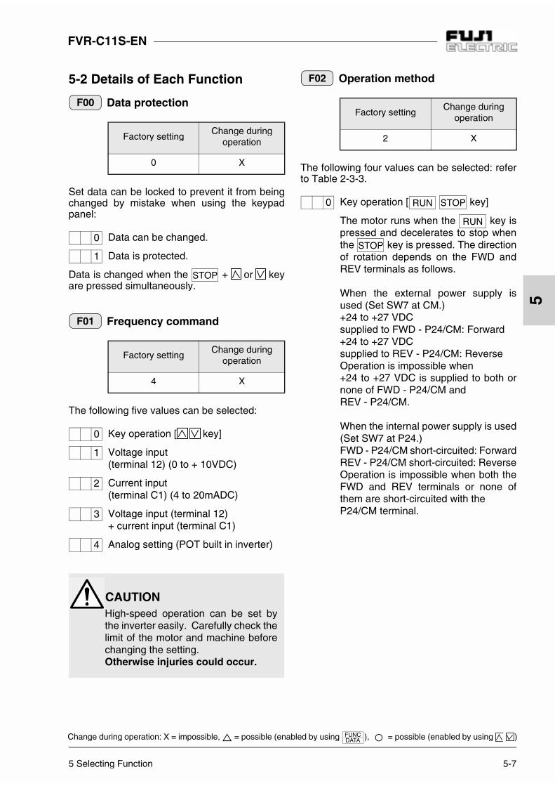
5-2 Details of Each Function
Data protection
Set data can be locked to prevent it from beingchanged by mistake when using the keypadpanel:
Data can be changed.
Data is protected.
Data is changed when the + or keyare pressed simultaneously.
Frequency command
The following five values can be selected:
Key operation [ key]
Voltage input (terminal 12) (0 to + 10VDC)
Current input (terminal C1) (4 to 20mADC)
Voltage input (terminal 12) + current input (terminal C1)
Analog setting (POT built in inverter)
Operation method
The following four values can be selected: referto Table 2-3-3.
Key operation [ key]
The motor runs when the key ispressed and decelerates to stop whenthe key is pressed. The directionof rotation depends on the FWD andREV terminals as follows.
When the external power supply isused (Set SW7 at CM.)+24 to +27 VDC supplied to FWD - P24/CM: Forward+24 to +27 VDC supplied to REV - P24/CM: ReverseOperation is impossible when +24 to +27 VDC is supplied to both ornone of FWD - P24/CM and REV - P24/CM.
When the internal power supply is used(Set SW7 at P24.)FWD - P24/CM short-circuited: ForwardREV - P24/CM short-circuited: ReverseOperation is impossible when both theFWD and REV terminals or none ofthem are short-circuited with the P24/CM terminal.
Factory settingChange during
operation
0 X
Factory settingChange during
operation
4 X
F00
0
1
F01
0
1
2
3
4
CAUTIONHigh-speed operation can be set bythe inverter easily. Carefully check thelimit of the motor and machine beforechanging the setting.Otherwise injuries could occur.
Factory settingChange during
operation
2 X
F02
0
FVR-C11S-EN
5-8 5 Selecting Function
5
Change during operation: X = impossible, = possible (enabled by using ), = possible (enabled by using )
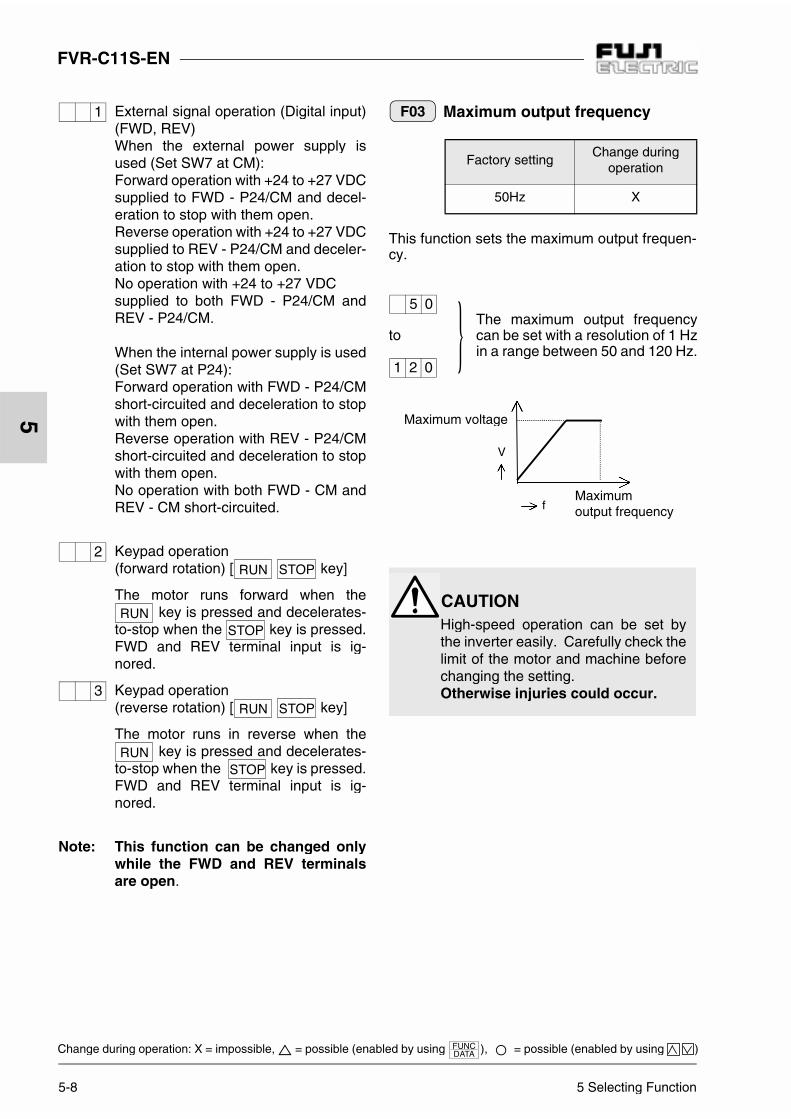
External signal operation (Digital input)(FWD, REV)When the external power supply isused (Set SW7 at CM):Forward operation with +24 to +27 VDCsupplied to FWD - P24/CM and decel-eration to stop with them open.Reverse operation with +24 to +27 VDCsupplied to REV - P24/CM and deceler-ation to stop with them open.No operation with +24 to +27 VDC supplied to both FWD - P24/CM andREV - P24/CM.
When the internal power supply is used(Set SW7 at P24):Forward operation with FWD - P24/CMshort-circuited and deceleration to stopwith them open.Reverse operation with REV - P24/CMshort-circuited and deceleration to stopwith them open.No operation with both FWD - CM andREV - CM short-circuited.
Keypad operation (forward rotation) [ key]
The motor runs forward when the key is pressed and decelerates-
to-stop when the key is pressed.FWD and REV terminal input is ig-nored.
Keypad operation (reverse rotation) [ key]
The motor runs in reverse when the key is pressed and decelerates-
to-stop when the key is pressed.FWD and REV terminal input is ig-nored.
Note: This function can be changed onlywhile the FWD and REV terminalsare open.
Maximum output frequency
This function sets the maximum output frequen-cy.
1
2
3
Factory settingChange during
operation
50Hz X
The maximum output frequencycan be set with a resolution of 1 Hzin a range between 50 and 120 Hz.
to
F03
5 0
1 2 0
f
V
Maximum voltage
Maximumoutput frequency
CAUTIONHigh-speed operation can be set bythe inverter easily. Carefully check thelimit of the motor and machine beforechanging the setting.Otherwise injuries could occur.

5 Selecting Function 5-9
FVR-C11S-EN
5
Change during operation: X = impossible, = possible (enabled by using ), = possible (enabled by using )
Base frequency
This function sets a base frequency (branchpoint between constant torque characteristicand constant output characteristic).
Set a frequency matching the motor characteris-tics.A value exceeding the maximum frequency canbe set but the output voltage is reduced.
Data cannot be changed.
Acceleration time
0.01 is set when 0.0 is specified.
Deceleration time
Factory settingChange during
operation
50Hz X
The base frequency can be setwith a resolution of 1 Hz in a rangebetween 25 and 120 Hz..
to
Factory settingChange during
operation
0 X
F04
2 5
1 2 0
V
f
Maximum voltage
Basefrequency
F05
F06
Factory settingChange during
operation
6. 0s
The time taken to increase from0.0 Hz to the maximum output fre-quency can be set in an incrementof 0.1 s step in a range between0.0 and 60.0 s.
to
Factory settingChange during
operation
6. 0s
The time taken to increase fromthe maximum output frequency to0.0 Hz can be set in a range be-tween 0.1 and 60.0 s. (In an incre-ment of 0.1 s step)
to
F07
0. 0
6 0. 0
F08
0. 1
6 0. 0

FVR-C11S-EN
5-10 5 Selecting Function
5
Change during operation: X = impossible, = possible (enabled by using ), = possible (enabled by using )
Torque boost
This function can choose between 32 types ofboost according to the load type and motor char-acteristics.
Set when using a FUJI inverter motor
(FV motor).
Electronic thermal O/L relay(Select)
This function is used to select between the fol-lowing three values:
Inactive
Active . . . . . . . . . 4-pole standard motor
Operation (inverter motor). . . 4-pole FUJI inverter motor
Electronic thermal O/L relay(Level)
Set the value obtained by multiplying the motorrated current by coefficient K in the table belowaccording to the wiring length between the in-verter and motor.
Factory settingChange during
operation
13
For square law torque loads (fan, pump)to
Lower
to
Higher
F09
0
1
2
3 1
Outputvoltage
Higher
Lower
Output frequency f
Square law torque
8
Factory settingChange during
operation
1
Factory settingChange during
operation
Motor rated current
to
This function sets the operationlevel of an electronic thermal O/Lrelay by using an ampere value ac-cording to the motor rated current.20 to 135% of the inverter ratedcurrent can be set.Values less than 9.99A can be setin 0.01A step and values morethan 10.0A can be set in 0.1A step.
Inverter capacityWiring length
0m 40m 50m 100m 200m
0.1C11S-7EN K=1.2External thermal is
recommended.0.2C11S-7EN K=1 K=1.1 K=1.20.4C11S-7EN K=1 K=1.10.75C11S-7EN
to2.2C11S-7EN
K=1
F10
0
1
2
F11
0. 1 4
2 2. 3

5 Selecting Function 5-11
FVR-C11S-EN
5
Change during operation: X = impossible, = possible (enabled by using ), = possible (enabled by using )
Electronic thermal O/L relay(thermal time constant)
The figure below shows the continuous permis-sible current with F10 (electronic thermal O/L re-lay [Select]) = 1.
The figure below shows the continuous permis-sible current with F10 (electronic thermal O/L re-lay [Select]) = 2. 100% of the continuouspermissible current is the current value set withfunction F11 (electronic thermal O/L relay [Lev-el]).
The graph below shows the electronic thermalO/L relay operating characteristics. Output cur-rent values for the electronic thermal operatinglevels (values set with function F11) are plottedhorizontally and operating times for output cur-rent are plotted vertically.This graph is for F10 = 1 with the base frequencyof 50Hz. The characteristics for output frequen-cies exceeding the base frequency are the sameas the characteristics for the base frequency.When function F10 is set to 2, the characteristicsare always the same as those for the base fre-quency. The operating time with output currentof 150% can be adjusted by using function F12(electronic thermal O/L relay (thermal time con-stant)).
Factory settingChange during
operation
5. 0min
to
This function sets the operatingtime of the electronic thermal O/Lrelay when the current that is150% of the operation level flows.0.5 to 10.0 min. can be set (in 0.1 min. step).
F12
0. 5
1 0. 0
0
20
40
60
80
100
120
0 0.2 0.4 0.6 0.8 1
Continuous permissible current (F10=1)
Output frequency/base frequency
perm
issi
ble
Con
tinuo
uscu
rren
t (%
)
0
20
40
60
80
100
120
0 0.2 0.4 0.6 0.8 1
Continuous permissible current (F10=2)
Output frequency/base frequency
perm
issi
ble
Con
tinuo
uscu
rren
t (%
)
0
5
10
15
20
1Hz 5Hz 20Hz 30Hz50Hz
0 50 100 150 200
Operating time characteristics
Output current/set operating level (%)
Ope
ratin
g tim
e (m
inut
e)
Setwith F12
(Base frequency)

FVR-C11S-EN
5-12 5 Selecting Function
5
Change during operation: X = impossible, = possible (enabled by using ), = possible (enabled by using )
Restart after momentarypower failure (Select)
This function determines whether operation isrestarted upon recovery from momentary powerfailure:
Inactive
Failure while inverter is stopped:The stop status is continued after recovery from the failure.
Failure during operation:LU indication is held immediatelydue to undervoltage and the invertertrips with alarm output.
Inactive
Failure while inverter is stopped:The stop status is continued after recovery from the failure.
Failure during operation:LU indication is held upon recoveryfrom the failure and the inverter trips with alarm output.
ActiveThe inverter restarts with the frequencyat the momentary power failure when0.5s elapses after recovery from the fail
ActiveThe inverter restarts with the startingfrequency when 0.5s elapses after re-covery from the failure.
,
= valid upon recovery from the failurewith LU being on.
The table below lists approximate LU indicationtimes for a momentary power failure during op-eration.
Frequency limiter (High)
Frequency limiter (Low)
This function sets the upper and lower limits ofoutput frequencies.
If the upper limit and lower limit settings are re-versed, the upper limit is valid and the lower limitis ignored.Hence, the operation is always performed withthe upper limit regardless of the frequency set-ting.
Factory settingChange during
operation
0 X
Inverter Type (kW) 0.1 0.2 0.4 0.75 1.5 2.2
Time (s) 0.6 1.2 2.6 4.8 3.0 5.0
F14
0
1
2
3
2
3
Factory settingChange during
operation
70Hz
Factory settingChange during
operation
0
0 to 120Hz can be set with a reso-lution of 1Hz.to
F15
F16
0
1 2 0

5 Selecting Function 5-13
FVR-C11S-EN
5
Change during operation: X = impossible, = possible (enabled by using ), = possible (enabled by using )
Gain(for frequency setting signal)
This function outputs the frequency obtained bymultiplying the reference frequency by a ratio.
This function selects an analog input signal level
with a value from to that is set by
function .
The maximum frequency is output at+10VDC (20mA DC).
The maximum frequency is output at+5VDC (12mADC).
When this function is used with function (bias frequency ), the gain set with this functionis valid and the gained frequency is biased.
Bias frequency
This function outputs a frequency biased for theanalog frequency setting.
DC injection brake (starting frequency)
This function sets 3.0Hz (fixed) as the startingfrequency of DC injection brake.
DC injection brake (Level)
This function sets a DC brake current level.Levels can be set in 1% unit by assuming thelevel of the inverter rated current to be 100%.
Factory settingChange during
operation
0 X
F17
1 4
F 0 1
0
1
F 1 8
100%
+10Vdc+5 0
20mAdc 12 4
Frequencysetting
1 0
Factory settingChange during
operation
0
to
Factory settingChange during
operation
3.0Hz X
Factory settingChange during
operation
50%
F18
-1 2 0
1 2 0
0% 0
4 20mAdc
100%Frequencysetting
Bias(negative)
Bias (positive)
+10VDC20mADC
F20
F21
-120 to 120Hz can be set witha resolution of 1Hz.
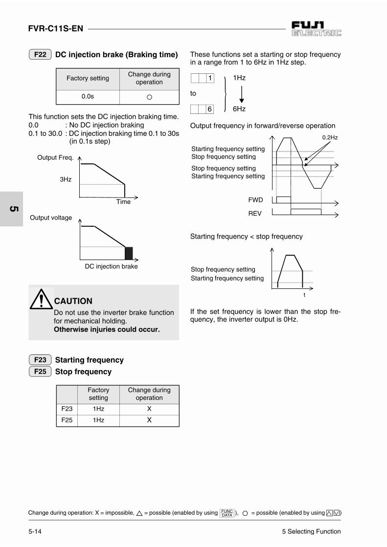
FVR-C11S-EN
5-14 5 Selecting Function
5
Change during operation: X = impossible, = possible (enabled by using ), = possible (enabled by using )
DC injection brake (Braking time)
This function sets the DC injection braking time.0.0 : No DC injection braking0.1 to 30.0 : DC injection braking time 0.1 to 30s
(in 0.1s step)
Starting frequency
Stop frequency
These functions set a starting or stop frequencyin a range from 1 to 6Hz in 1Hz step.
Output frequency in forward/reverse operation
Starting frequency < stop frequency
If the set frequency is lower than the stop fre-quency, the inverter output is 0Hz.
Factory settingChange during
operation
0.0s
Factorysetting
Change duringoperation
F23 1Hz X
F25 1Hz X
F22
Time
DC injection brake
Output voltage
Output Freq.
3Hz
CAUTIONDo not use the inverter brake functionfor mechanical holding.Otherwise injuries could occur.
F23
F25
1Hz
to
6Hz
1
6
0.2Hz
Starting frequency settingStop frequency setting
Stop frequency settingStarting frequency setting
FWD
REV
Stop frequency settingStarting frequency setting
t

5 Selecting Function 5-15
FVR-C11S-EN
5
Change during operation: X = impossible, = possible (enabled by using ), = possible (enabled by using )
Data cannot be changed.
Motor sound (carrier freq.)
This function changes the motor tone quality bychanging the carrier frequency.
Data code 0 : 0.75kHz (Low carrier)1 : 1kHz2 : 2kHz15 : 15kHz (High carrier, low noise)
Note: When the inverter is operating at 9kHzor higher carrier frequency, the carrierfrequency for may be reduced to 8kHzautomatically to protect the inverter.
Motor sound (sound tone)
This function adjusts the motor operation soundwhen a value of 7 or less is set with function F26.
Level 0
to
Level 3
FM terminal (voltage adjust)
This function regulates the frequency meter volt-age level output to the FM terminal in the rangefrom 0 to 200% (in 1% step).
Note: Output to the FM terminal is pulse out-put with constant frequency and varia-ble duty.
Factory settingChange during
operation
0. 0 -
Factory settingChange during
operation
15kHz
Choose among 16 types accordingto the usage conditions.to
Factory settingChange during
operation
0
F24
F26
0
1 5
F27
0
3
Factory settingChange during
operation
100%
(Full scale about 0VDC)
to
(Full scale about 11VDC)
F30
0
2 0 0
200%
10V 100%
5V 50%
50% 100%
11V
Output/full scale
Outputvoltage
Variable
Fixed to 121.6Hz
Approx. 13V

FVR-C11S-EN
5-16 5 Selecting Function
5
Change during operation: X = impossible, = possible (enabled by using ), = possible (enabled by using )
FM terminal (Function)
This function selects the contents of output tothe FM terminal.
Output frequency(maximum output frequency = 100%)
Output current (inverter rated current x 2 = 100%)
PID feedback value (full scale = 100%)
DC link circuit voltage(500VDC = 100%)
30Ry operation mode
This function sets the operation mode of alarmoutput for any fault (30Ry).
1) The status without inverter power supply is the same asthe status when inverter is tripped.
X1 terminal (function selection)
X2 terminal
X3 terminal
Multistep frequency selection 1 (SS1)
Multistep frequency selection 2 (SS2)
f1: Frequency selected with F01(keypad panel/analog/freq. setting POT )
f2: Frequency selected with C05f3: Frequency selected with C06f4: Frequency selected with C07
OFF input is assumed if SS1 or SS2 is not se-lected.
Factory settingChange during
operation
0
Factory settingChange during
operation
0 X
F36 Normal operation Tripped
0(Excited
whentripped)
1(Normallyexcited)
F31
0
1
2
3
F36
30A
30B
30C
30A
30B
30C
30A
30B
30C
30A
30B
30C
Factorysetting
Change duringoperation
E01 0 X
E02 2 X
E03 3 X
E01
E02
E03
0
1
f3f2
f1 f4
FWD-P24/CM
(SS1)-P24/CM
(SS2)-P24/CM
t
ON ON
ON
ON
Outputfrequency
1)

5 Selecting Function 5-17
FVR-C11S-EN
5
Change during operation: X = impossible, = possible (enabled by using ), = possible (enabled by using )
Coast-to-stop command (BX)Inverter output is cut when the BX ter-minal is connected to the P24/CM ter-minal.OFF input is assumed when BX is notselected.
Alarm reset (RST)The alarm output is released betweenthe RST and P24/CM terminals whenpower is turned on.The trip status is released between theRST and P24/CM terminals when pow-er is turned off. (Refer to 6-2 Alarm Reset on page 6-3)
External alarm (THR)Inverter trips with OH2 when the THRterminal is disconnected from the P24/CM terminal.ON input is assumed when THR is notselected.
Write enable command for keypad(WE-KP)Function change from the keypad panelis disabled when the WE-KP terminal isdisconnected from the P24/CM termi-nal.Function change from the keypad panelis enabled when the WE-KP terminal isconnected to the P24/CM terminal.ON input is assumed when WE-KP isnot selected.
PID control cancel (Hz/PID)PID control operates when the Hz/PIDterminal is disconnected from the P24/CM terminal and does not operatewhen they are connected.OFF is assumed when the Hz/PID isnot selected.
Hz/PID is valid only when function
is set to or .
(PID control operation).
Link operation selection (LE)Operation setting can be done by com-mands from RS485 when the LE termi-nal is connected to the P24/CMterminal.A command from RS485 is ignoredwhen the LE terminal is disconnectedfrom the P24/CM terminal.ON input is assumed when LE is not se-lected.
LE is valid only when function is
set to (option operation).
2
3
4
5
6
H 2 0 1 2
7
o 0 0
1

FVR-C11S-EN
5-18 5 Selecting Function
5
Change during operation: X = impossible, = possible (enabled by using ), = possible (enabled by using )
Jump frequency 1, 2, 3
These functions jump frequencies to preventoverlap between the load mechanical resonancepoint and inverter output frequency.Up to three jump points can be set.These function do not operate when 0Hz is set.No frequency is jumped during acceleration anddeceleration.If three continuous frequencies are set, the totalof the three jump widths is set as the jump width.
Jump frequency (Hysteresis)
This function sets a jump width in a range from 0to 30Hz in 1Hz step.
Multistep frequency 1Multistep frequency 2
Multistep frequency 3
These functions set a multistep frequency from 0to 120Hz in 0.1Hz step (for 99.9 Hz or less) or1Hz step (for 100Hz or more) by switching theexternal contact signal.The ON and OFF of terminal function SS1/SS2(see explanation of E01, E02, and E03) switchesbetween the frequencies set by these functionsC05, C06, and C07.
Motor characteristics
This function removes abnormalities in the out-put current such as current vibration.
Current vibration is not suppressed.
to
Current vibration is minimized.
Factorysetting
Change duringoperation
C01 0.0Hz
C02 0.0Hz
C03 0.0Hz
Factory settingChange during
operation
3Hz
C01
C02
C03
Jump frequency
Jump frequency
Jump frequency
Jump frequency
Jump width
Jump width
Jump width
Output frequency
C04
Factorysetting
Change duringoperation
C05 0.0Hz
C06 0.0Hz
C07 0.0Hz
Factory settingChange during
operation
2
C05C06
C07
P00
0
1 0

5 Selecting Function 5-19
FVR-C11S-EN
5
Change during operation: X = impossible, = possible (enabled by using ), = possible (enabled by using )
Operation time
This function displays the integration time ofpower supply applied to the inverter.0 to 655 are displayed to indicate 0 to 65500hours.If the integration time exceeds 65500 hours,65500 is displayed continuously. While the totalof power supply times is less than one hour, thetimes are not integrated.
Trip history
This function memorizes the history of the lastfour protection operations.Each data item can be called using the key.The calling procedure is shown below:
The contents of a new alarm is stored in the dataarea for the history of the latest alarm. At thistime, the history of the latest alarm is stored inthe data area for the second latest alarm. Thehistories of the second and third latest alarms aremoved in this way and the history of the fourthlatest alarm is deleted.Stored trip histories are not deleted althoughdata initialization is executed with H03.
H01 H02
No. Procedure Displayexample Remarks
1 Call
2 Press the key Press the key The contents (history) of thelatest alarm are displayed.
3 Press the key Press the key The contents of the second lat-est alarm are displayed.
4 Press the key Press the key The contents of the third latestalarm are displayed.
5 Press the key Press the keyThe contents of the fourth lat-est alarm are displayed. (Thisexample is for no history.)
6 Press the key
H 0 2 H 0 2
O U 2
O H 2
O C 1
- - -
E n d

FVR-C11S-EN
5-20 5 Selecting Function
5
Change during operation: X = impossible, = possible (enabled by using ), = possible (enabled by using )
Data initialization
This function initializes data items set with allfunctions to values set in the factory.
Manually set value
to
Initialized (factory set value)
The display is changed from to
when the and keys are pressed simul-
taneously.
When the key is pressed under this
condition, initial data is written and a frequencyset by the built-in POT (VR) is displayed auto-matically.
Retry
This function selects a retry operation if the in-verter is tripped.
: No retry
to
: The retry count is fixed to 5 and retrystarts when 0.5s elapses after tripping.
Retry is attempted only for an overcurrent/over-voltage trip that occurs during operation.
Cooling fan on/off control
: ON-OFF No control (always on)
to
: ON-OFF Control(The fan is turned off when the invertertemperature becomes low after opera-tion is stopped.)
PID control (Mode select)
The feedback signal value (%) is displayed byassuming the full scale to be 100% when a PIDcontrol operation is selected.
Factory settingChange during
operation
0 X
Factory settingChange during
operation
0
H03
0
1
0 1
H04
0
1
Factory settingChange during
operation
0
Factory settingChange during
operation
0 X
: Inactive
Select a PID control operation.: Active (forward)
: Active (reverse)
H06
0
1
H20
0
1
2

5 Selecting Function 5-21
FVR-C11S-EN
5
Change during operation: X = impossible, = possible (enabled by using ), = possible (enabled by using )
PID control(Feedback signal select)
This function selects a PID control feedback sig-nal.
Terminal 12 (0 to +10VDC)
Terminal C1 (4 to 20mADC)
Terminal 12 (+1 to +5VDC)
PID control (P-gain)
This function sets a P-gain.
to P-gain from 0.01 to 10.0times (1 to 1000%)(in increment of 0.01 step)
PID control (I-gain)
This function sets an integral time.
: No integration
to : Integral time 0.1 to 999s
(in 0.1s step for 99.9s or less, 1s step for 100s ormore)
PID control (D-gain)
This function sets a derivative time.
: No derivative
to : Derivative time 0.01 to 10.0s (in 0.01s step)
PID control (Feedback filter)
This function sets a filter time constant of PIDfeedback.
to : Time constants 0.0 to 60.0s (in 0.1s step)
Factory settingChange during
operation
1 X
Factory settingChange during
operation
0.01
Factory settingChange during
operation
0.0s
H21
0
1
2
H22
0. 0 1 1 0. 0
H23
0. 0
0. 1 9 9 9
Factory settingChange during
operation
0.00s
Factory settingChange during
operation
0.5s
H24
0. 0 0
0. 0 1 1 0. 0
H25
0. 0 6 0. 0

5-22 5 Selecting Function
FVR-C11S-EN
5
Change during operation: X = impossible, = possible (enabled by using ), = possible (enabled by using )
PID control
In PID control, an output frequency is adjusted toa feedback value.
Use to set a frequency and tomake the feedback value and the reference valueequal.
Option selection(RS485 communication)
: Option inactive
: Option active
Always set when the optional RS485 se-rial communication unit is not used. If isset, Er 8 occurs.
For explanations of "o01" to "o11", refer tothe instruction manual that comes with theoptional RS485 serial communication unit.
F 0 1 H 2 1
Kp M P(11
s Tis Td)⋅ +
-
+ ⋅+ ⋅
FVR-C11S-EN
Deviation is positive and frequency decreases.
Referencefrequency
PID arithmetic unitSwitchingbetween FWD and REV operation
Inverteroutput
Deviation
Feedback value (sensor)
Kp : P-gainTd : Derivative timeTi : Integral time
Forwardoperation
Reverseoperation
Deviation
Outputfrequency
Deviation
Outputfrequency
Deviation is positive and frequency increases.
o00
Factory settingChange during
operation
0
0
1
01

6 Protective Function 6-1
FVR-C11S-EN
6
6 Protective Function
6-1 List of protec-tive functions
When the protective function is activated, inverter output is instantly cutoff (while the motor coasts until it is stopped), and an alarm is issued,and the details of the alarm are displayed on the keypad panel.
Alarm NameKeypadpanel
displayContents of operation
Overcurrent
OC1 Duringacceleration If the inverter output current momentarily ex-
ceeds the overcurrent detection level because ofan overcurrent in the motor or the short-circuit inthe output circuit, the output is shut down, analarm is issued, and the inverter is tripped.
OC2 Duringdeceleration
OC3 While running atconstant speed
Overvoltage
OU1 Duringacceleration
If the DC voltage of the main circuit exceeds theovervoltage detection level because of an in-crease in the regenerating current from the mo-tor, etc., output is shut down, an alarm is issued,and the inverter is tripped. However, protectionagainst inadvertent overvoltage loading (e.g.high-voltage line) might not be provided.
OU2 Duringdeceleration
OU3 While running atconstant speed
Undervoltage LU
If the DC voltage of the main circuit falls below the undervoltage de-tection level because of a lowered power supply, output is shut downto protect the inverter. If the restart function after momentary powerfailure is not activated, an alarm is issued and the inverter is tripped.If the restart function is activated, the inverter restarts automaticallywith no alarm.For further details of the protective function, refer to the descriptionsof Function F14.
Overheating ofheat sink OH1
If the temperature of the heat sink used for cooling the rectifier diodesand IGBTs rises because of cooling fan failure, etc., protective func-tion is activated to stop operation, an alarm is issued, and the inverteris tripped.
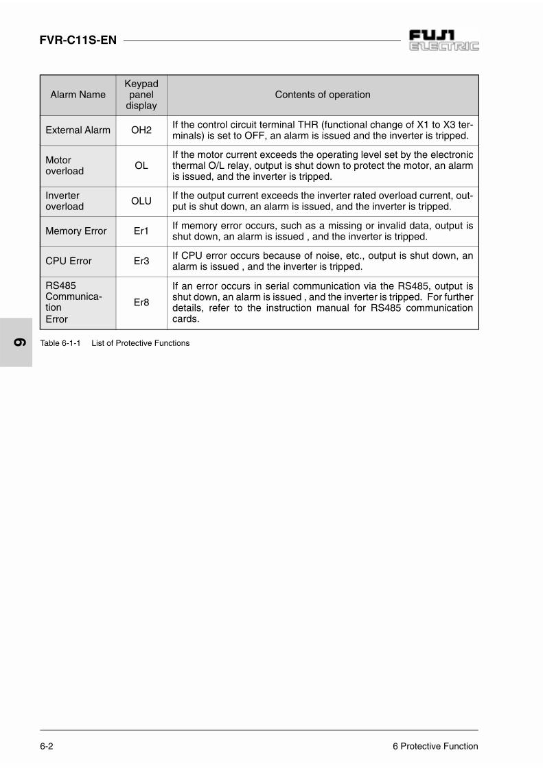
6-2 6 Protective Function
FVR-C11S-EN
6
Table 6-1-1 List of Protective Functions
Alarm NameKeypadpanel
displayContents of operation
External Alarm OH2 If the control circuit terminal THR (functional change of X1 to X3 ter-minals) is set to OFF, an alarm is issued and the inverter is tripped.
Motoroverload OL
If the motor current exceeds the operating level set by the electronicthermal O/L relay, output is shut down to protect the motor, an alarmis issued, and the inverter is tripped.
Inverteroverload OLU If the output current exceeds the inverter rated overload current, out-
put is shut down, an alarm is issued, and the inverter is tripped.
Memory Error Er1 If memory error occurs, such as a missing or invalid data, output isshut down, an alarm is issued , and the inverter is tripped.
CPU Error Er3 If CPU error occurs because of noise, etc., output is shut down, analarm is issued , and the inverter is tripped.
RS485Communica-tionError
Er8
If an error occurs in serial communication via the RS485, output isshut down, an alarm is issued , and the inverter is tripped. For furtherdetails, refer to the instruction manual for RS485 communicationcards.

6 Protective Function 6-3
FVR-C11S-EN
6Figure. 6-2-1 How to input the reset command
6-2 Alarm Reset To release the trip status, enter the reset command by pressing the re-set key or from terminal (RST) after removing the cause of the trip.Since the reset command is an edge operation, be sure to input a com-mand string such as OFF ON OFF as shown in Figure 6-2-1.When releasing the trip status, set the operation command to OFF.When the operation command is set to ON, check that operation startsafter resetting.If the cause of tripping is Er1, reset the error and initialize data. If theinverter is not reset, contact Fuji Electric.
If alarm reset is activated with operation signal ON, the inverter sud-denly restarts which may be hazardous. Be sure to disable the oper-ating signal when releasing the trip status:Otherwise fire could occur.
Reset command
Keypad panel display
Alarm output
Normal display Alarm display Normal display
OFF OFFON
OFF OFFON
10ms or more
Trip
WARNING

7-1 7 Troubleshooting
FVR-C11S-EN
7
7 Troubleshooting
1) Overcurrent (OC)
7-1 In case of tripping
In the event the inverter tripping, diagnose by the help of the alarm dis-play as shown below.
Overcurrentduring
accelerationOC1
Overcurrentduring
decelerationOC2
Overcurrentwhile running at constant speed
OC3
Are the motor connecting terminal (U,V,W)short-circuited or grounded?
Yes Removeshort-circuitor ground.
No No No
Load excessive? YesReduce load
or expand inverter
capacity.
No No No
NoCan torque
boost amount be reduced?
No Torqueboost amount
correct?
Decelerationtime setting
too short com-pared
with load?
No
Faulty invert-er or error
’because of noise.
ContactFuji Electric.
Yes Yes Yes Has load changedsuddenly?
No
Reducetorque boost
amount.
Acceleration time setting too short compared
with load?
No
Yes
Prolongtime setting.
YesCan the
accelerationtime setting be
prolonged?
Can the deceleration
time setting be prolonged?
Yes Prolongtime setting.
No No
Reduce load or expand inverter
capacity.
Braking method needs investiga-tion. Consult with
Fuji Electric.
Suppress load fluctuation or
expand inverter capacity.
Yes
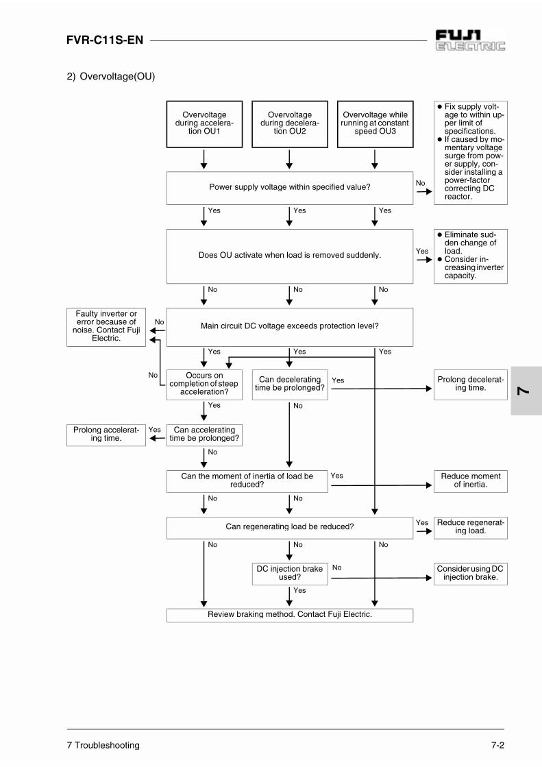
7 Troubleshooting 7-2
FVR-C11S-EN
7
2) Overvoltage(OU)
Overvoltageduring accelera-
tion OU1
Overvoltageduring decelera-
tion OU2
Overvoltage while running at constant
speed OU3
Fix supply volt-age to within up-per limit of specifications.
If caused by mo-mentary voltagesurge from pow-er supply, con-sider installing a power-factorcorrecting DC reactor.
Power supply voltage within specified value? No
Yes Yes Yes
Does OU activate when load is removed suddenly. Yes
Eliminate sud-den change of load.
Consider in-creasing inverter capacity.
No No No
Faulty inverter or error because of
noise. Contact Fuji Electric.
No Main circuit DC voltage exceeds protection level?
Yes Yes Yes
No Occurs on completion of steep
acceleration?
Can deceleratingtime be prolonged?
Prolong decelerat-ing time.
Yes No
Prolong accelerat-ing time.
Yes Can acceleratingtime be prolonged?
No
Can the moment of inertia of load be reduced?
Reduce moment of inertia.
No No
Can regenerating load be reduced? Yes Reduce regenerat-ing load.
No No No
DC injection brake used?
Consider using DC injection brake.
Yes
Review braking method. Contact Fuji Electric.
Yes
Yes
No
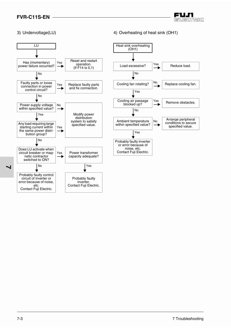
FVR-C11S-EN
7-3 7 Troubleshooting
7
3) Undervoltage(LU) 4) Overheating of heat sink (OH1)
LU
Has (momentary)power failure occurred?
Yes Reset and restart operation.
(If F14 is 0,1)
No
Faulty parts or loose connection in power
control circuit?
Yes Replace faulty parts and fix connection.
No
Power supply voltagewithin specified value?
No
Modify power distribution
system to satisfyspecified value.
Yes
Any load requiring largestarting current within the same power distri-
bution group?
Yes
No
Does LU activate when circuit breaker or mag-
netic contractor switched to ON?
Yes Power transformer capacity adequate?
No Yes
Probably faulty control circuit of inverter or
error because of noise, etc.
Contact Fuji Electric.
Probably faultyinverter.
Contact Fuji Electric.
Heat sink overheating(OH1)
Load excessive? Yes Reduce load.
No
Cooling fan rotating? No Replace cooling fan.
Yes
Cooling air passageblocked up?
Yes Remove obstacles.
No
Ambient temperature within specified value?
No Arrange peripheral conditions to secure
specified value.
Yes
Probably faulty inverter or error because of
noise, etc. Contact Fuji Electric.

7 Troubleshooting 7-4
FVR-C11S-EN
7
5) External alarm input (OH2) 6) Inverter overload (OLU) or motor overload(OL)
OH2
Signal from external device connected
between control circuit terminals
THR - P24/CM?
No
Connect alarm signalcontact. Short-circuit
between terminals THR - P24/CM if no
signal is input.
Yes
Is the alarm function of the external device operating correctly?
NoProbably faulty
inverter or error be-cause of noise.
Contact Fuji Electric.
Yes
Remove the cause of alarm function
activation.
OLU OL
Do characteris-tics of electronic thermal O/L relayand those of mo-
tor overload match?
No Connect thermal O/L relayexternally.
Yes
Is electronic ther-mal O/L relay set-
ting correct?
No Set to correct level.
Yes
Load excessive? No
Probably faultyinverter or error
because of noise, etc. Contact
Fuji Electric.
Yes
Reduce load or increase inverter
capacity

7-5 7 Troubleshooting
FVR-C11S-EN
7
7) Memory error (Er1) CPU error (Er3)
Abnormaldisplay or indi-cation goes out
Memory error Er 1 CPU error Er 3Analog frequen-
cy set to negativevalue?
Yes
Reset analog fre-quency to positive
value.
Turn power OFF then ON again after CHARGE lamp has gone out.
Is data displayedon LED?
No Noise source nearby?
Yes Remedy faultyparts.
Yes No
Inverter is normal. Continueoperation.
Probably faultyinverter. Contact
Fuji Electric.
No

7 Troubleshooting 7-6
FVR-C11S-EN
7
8) RS485 Communication Error (Er8) [In case RS485 communication is not used*]
* For Er8 measures when using RS485, refer to the instruction manual for optional RS485 communication card.
CommunicationError Er8
o00 is set to 1? No Probably faultyinverter.
Contact Fuji Electric.
Yes
Set o00 to 0.

7-7 7 Troubleshooting
FVR-C11S-EN
7
7-2 Other trouble 1) When motor does not rotate.
Note: Verify the function settings for the operation commands andfrequency setting values on the keypad panel.
Motor does not start.
Does charge lamp light? NoAre circuit breaker and magnetic contactor on
power supply side switched ON?
NoInvestigate cause of failed switching, and
turn them ON if there is no problem.
Yes Yes
Remedy failed function and start after resetting
alarm.
Yes Alarm displayed on keypad panel?
Voltage of main power supply input terminals
normal?
No
Check for failures such as low voltage,
phase failure, loose connection, and poor contact, and remedy
accordingly.
No
If no error is detected, continue operation.
Is the operation method the keypad panel or
input signal?
Possibly of faultyinverter.
Contact Fuji Electric.
Yes
Does motor run if RUN key is pressed?
No Forward or reverse operation command
given?
NoExternal wiring between control circuit terminals FWD, REV - P24/CM connected correctly?
Yes Replace faulty switch or relay.
No
Press UP key and set frequency. Remedy wiring error.
Yes
Does inverter start when UP key pressed?
No Does frequency settingexceed starting and
stop frequency.
No
Setting of built-in POT (VR) and
connections of external circuit wiring between
control circuit terminals 13,12,11,C1 or X1, X2, X2 - P24/CM correct?
Yes
Replace faultyfrequency settingPOT (VR), signalconverter, switch,
or relay contacts as appropriate.
No
Yes
Keypadpanel
Inputsignal
Yes YesNo
No
Yes Yes
(Continued)

7 Troubleshooting 7-8
FVR-C11S-EN
7
Execute correct frequency setting.
YesAre the frequency
limiter (High) and the frequency setting lower than starting frequency?
No
Defective motor.Inverter output terminals (U,V,W) supplied with
proper voltage?
No Probably faulty inverter. Contact Fuji Electric.
No Yes
Load excessive? Yes Motor wiring correct? No Remedy wiring error.
Yes
Setting of torque boost amount correct?
Yes
Load is excessive, re-sulting in motor lock.Lighten load. Also,
check that the brake is adequately released if mechanical brake is
used.
No
Raise torque boost amount.
The motor does not rotate if the following com-mands are given.
1. An operation command is given whilecoast-to-stop command is output to thecontrol terminals.
2. Both operation command FWD and REVare input.
Yes Yes
(Continued)
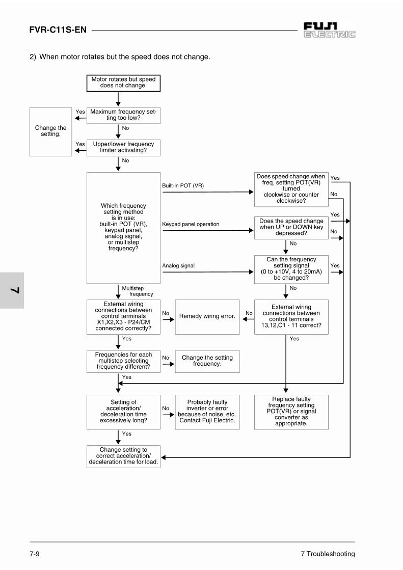
7-9 7 Troubleshooting
FVR-C11S-EN
7
2) When motor rotates but the speed does not change.
Motor rotates but speed does not change.
Change the setting.
Yes Maximum frequency set-ting too low?
No
Yes Upper/lower frequencylimiter activating?
No
Which frequencysetting method
is in use: built-in POT (VR),
keypad panel, analog signal,or multistep frequency?
Built-in POT (VR)
Does speed change when freq. setting POT(VR)
turnedclockwise or counter
clockwise?
Yes
No
Yes
NoKeypad panel operation Does the speed change
when UP or DOWN keydepressed?
No
Analog signalCan the frequency
setting signal(0 to +10V, 4 to 20mA)
be changed?
Yes
Multistep frequency
No
External wiringconnections between
control terminals X1,X2,X3 - P24/CM connected correctly?
No Remedy wiring error. NoExternal wiring
connections between control terminals
13,12,C1 - 11 correct?
Yes Yes
Frequencies for each multistep selecting
frequency different?
No Change the settingfrequency.
Yes
Setting of acceleration/
deceleration time excessively long?
NoProbably faultyinverter or error
because of noise, etc. Contact Fuji Electric.
Replace faultyfrequency settingPOT(VR) or signal
converter as appropriate.
Yes
Change setting to correct acceleration/
deceleration time for load.
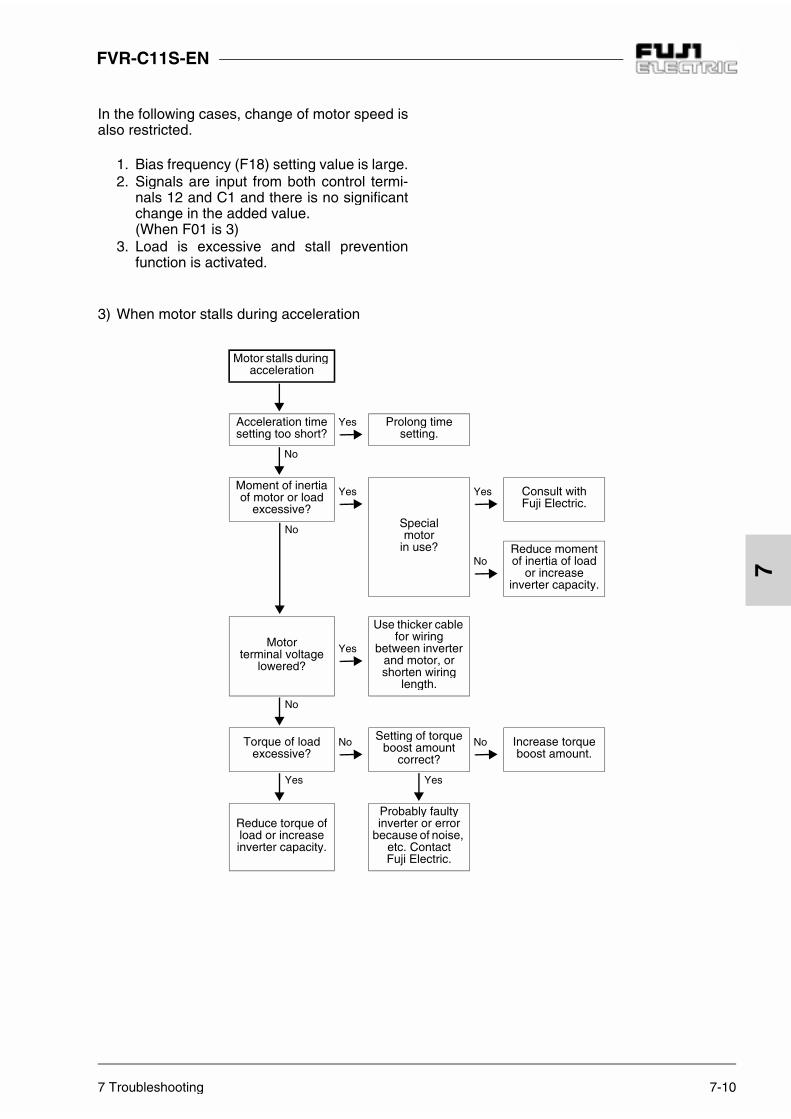
7 Troubleshooting 7-10
FVR-C11S-EN
7
3) When motor stalls during acceleration
In the following cases, change of motor speed isalso restricted.
1. Bias frequency (F18) setting value is large.2. Signals are input from both control termi-
nals 12 and C1 and there is no significantchange in the added value.(When F01 is 3)
3. Load is excessive and stall preventionfunction is activated.
Motor stalls duringacceleration
Acceleration time setting too short?
Yes Prolong time setting.
No
Moment of inertia of motor or load
excessive?
Yes
Specialmotor
in use?
Yes Consult with Fuji Electric.
No
NoReduce moment of inertia of load
or increase inverter capacity.
Motorterminal voltage
lowered?
Yes
Use thicker cable for wiring
between inverter and motor, or shorten wiring
length.
No
Torque of load excessive?
No Setting of torque boost amount
correct?
No Increase torque boost amount.
Yes Yes
Reduce torque of load or increase inverter capacity.
Probably faultyinverter or error
because of noise, etc. Contact Fuji Electric.

7-11 7 Troubleshooting
FVR-C11S-EN
7
4) When motor generates abnormal heat
Motor generates abnor-mal heat
V/f pattern fitted to mo-tor?
No Change the setting.
Yes
Motor been continuously operated
at extremely low speed?
Yes Use motor exclusive to inverter.
No
Load excessive? Yes Lighten load or in-crease motor capacity.
No
Is the output voltage (at terminals U,V,W)
balanced?
Yes Faulty motor.
No
Probably faulty inverter. Contact Fuji Electric.

7 Troubleshooting 7-12
FVR-C11S-EN
7
5) When function change disabled
Function change is disabled.
Any of E01, E02, E03 set to 5?
Yes
Short-circuit between terminals X1,X2,X3 corresponding to
function set to 5 and P24/CM terminal.
No
F00 set to 0? No Set F00 to 0.
Yes
Attempt made to change an
unchangeable function during operation?
Yes Change function after stopping inverter.
No
Function to be changedF00 or H03?
Yes Press STOP key and UP or DOWN keysimultaneously.
No
Function to be changedF02?
FWD or REV terminal connected to
P24/CM terminal?
Yes Open FWD and REV command.
No
Function to be changedF05, F06, F24, H01 or
H02?
Yes Change other functions.
No
Contact Fuji Electric.

FVR-C11S-EN
8-1 8 Maintenance and Inspection
8
8 Maintenance and Inspection
Execute the daily inspection and periodic in-spection for preventing a fault and ensuringlong-term reliability.Note the following regarding the work.
8-1 Daily Inspection
During the operation and conduction, the visualinspection for abnormal operation is executedfrom the outside without removing the covers.Inspections are usually done to check the follow-ing:1. The expected performance (satisfying the
standard specification) is obtained.
2. The environment satisfies the standard spec-ification.
3. The keypad panel display is normal.
4. There are no abnormal sound, vibrations orunpleasant odors.
5. There are no overheating marks or discolora-tion.
8-2 Periodic Inspection
The periodic inspection must be executed afterstopping the operation and cutting off the powersource and removing the surface cover.After power-off, time is needed for the smoothingcapacitors in the DC section in the main circuit todischarge. To prevent electric shock, make surethat the voltage falls down to the safety value(25VDC and below) using a multimeter after thecharge lamp (CRG) goes off.
WARNING
1. Start inspection five minutes or more afterturning off the power supply. (Check thatthe charge lamp (CRG) goes off, andcheck the voltage is 25V DC or below be-tween terminals P(+) and N(-).There is danger of electric shock.
2. Only the designated person can performthe maintenance and replace components.(Take off any metal objects such as awatch or ring.)(Use insulated tools.)
3. Never modify the inverter.There is danger of electric shock or in-jury.

8 Maintenance and Inspection 8-2
FVR-C11S-EN
8
Check part Check item How to inspect Evaluation criteria
Environment
1. Check the ambient air tem-perature, humidity, vibra-tion, atmosphere (dust, gasoil mist, waterdrops)
2. Are foreign matter or dan-gerous objects such astools not left around theequipment?
1. Measure by visu-al inspection andthe meter.
2. With visual in-spection
1. The specified stand-ard value must besatisfied.
2. No foreign matter ordangerous objectsleft near the inverter?
VoltageAre the voltages in the maincircuit and the control circuitnormal?
Measure with themultimeter.
The specified standardvalue must be satisfied.
Keypad panel
1. Is the display hard to read?
2. Are the characters com-plete?
1., 2. Visual inspection
1., 2. The display canbe read and is notabnormal.
Structure suchas a frame orcover
1. Abnormal sound or vibra-tion?
2. Loose bolts (part to be tightened) ?
3. Deformation or damage?
4. Discoloration by overheating?
5. Stains and dust?
1. With Visual in-spection andhearing
2. Tighten more
3., 4., 5.With visual inspection
1., 2., 3., 4., 5.Not abnormal.
Mai
n ci
rcui
t
Comon
1. Loose and missing bolts?
2. Deformation, cracks, dam-age, and discoloration byoverheating and deteriora-tion in the equipment andthe insulation?
3. Stains and dust?
1. Tighten more
2., 3. Visual inspection
1., 2., 3. Not abnormal.
Note: A discoloredshort-circuitingbar does not indicate a problem.

8-3 8 Maintenance and Inspection
FVR-C11S-EN
8
Check part Check item How to inspect Evaluation criteria
Mai
n ci
rcui
t
Conductorand wire
1. Discoloration and distortionof a conductor by overheat-ing?
2. Cracks, crazing, and discol-oration of the wire sheath?
1., 2. Visual inspection
1., 2. Not abnormal.
Terminalblock
Not damaged? Visual inspection Not abnormal.
Smooth-ingcapacitor
1. Electrolyte leakage, discol-oration, crazing, and swell-ing of a case?
2. Is a safety valve not out,and are any valves protrud-ing excessively?
3. Measure the capacitance ifnecessary
1., 2. Visual inspection
3. Measure usingthe capacitancemeasuringinstrument (Note)
1., 2. Not abnormal.
3. The capacitance is initial value x 0.85 ormore.
Mai
n ci
rcui
t
Resistor
1. Unpleasant smell and craz-ing of the insulation by over-heating
2. No open circuit?
1. Olfactory and vis-ual inspection
2. Visual inspectionor use a multime-ter by removing aconnection onone side.
1. Not abnormal.
2. Less than about±10% of the indicat-ed resistance value
Trans-formerandreactor
Abnormal buzzing or unpleasant smell?
Aural, olfactory, andvisual inspection
Not abnormal.
Magneticcontactorand relay
1. Rattling when operating?
2. Roughness of contact?
1. Aural
2. Visual inspection
1., 2. Not abnormal.

8 Maintenance and Inspection 8-4
FVR-C11S-EN
8
Table 8-2-1 Periodic inspection list
Check part Check item How to inspect Evaluation criteriaC
ontr
ol c
ircui
t
ControlPC boardandconnector
1. Loose screws or connec-tors?
2. Unpleasant smell or discoloration?
3. Cracks, damage, deforma-tion, or excessive rust?
4. Electrolyte leakage or a deformed mark on the capacitor?
1. Tighten more.
2. Olfactory and visual inspection
3., 4. Visual inspection
1., 2., 3., 4.Not abnormal.
Coo
ling
syst
em
Coolingfan(1.5 kWminimum)
1. Abnormal sound or vibration?
2. Loose of bolts?
3. Discoloration by overheating?
1. Aural and visualinspection. Turnwith hand. (Makesure power is off)
2. Tighten more
3. Visual inspection
1. The fan must rotatesmoothly.
2., 3. Not abnormal
Ventila-tion way
Clogging-up or foreign sub-stance on heat sink or intake/exhaust ports?
Visual inspection Not abnormal
Note: Use a capacitance measuring instru-ment available on the market which iseasy to use.
Remark: If the equipment is stained, wipe it witha cleaning cloth, which is chemicallyneutral.Vacuum-clean the dust.

8-5 8 Maintenance and Inspection
FVR-C11S-EN
8
Table 8-3-1 Meter for measuring the main circuit
1) When measuring the output voltage by rectifier type meter, an error may occur. Use a digital AC power meter for good accuracy.
8-3 Electrical measure-ments in the Main Circuit
The indicated values depend on the meter types because of harmoniccomponents included in the voltage and current of the main power sup-ply (input) and the output (motor) side of the inverter. Therefore, whenmeasuring with a meter for the commercial power frequency, use themeters shown in Table 8-3-1.
The power-factor cannot be measured using the power-factor meteravailable on the market which measures the phase difference betweenvoltage and current. When the power-factor must be measured, meas-ure the power, voltage, and current on the input side and output side.Then, calculate the power-factor using the following formulas:
Single-phase
Electric power [W]Power factor = x 100 [%]
Voltage [V] x Current [A]
Item
Input (power supply) side Output (motor) side DC circuit
Voltagewaveform
Currentwaveform
Voltagewaveform
Currentwaveform
P(+), N(-)FM, 11
Terminalsection
Metername
AmmeterAR
VoltmeterVR
WattmeterWR
AmmeterAU,V,W
VoltmeterVU,V,W
WattmeterWU,W
DCvoltmeter
V
Metertype
Moving-iron type
Rectifieror
moving-iron type
Powermeter
Moving-iron type
Rectifiertype 1)
Powermeter
Moving-coil type
Symbol - -

8 Maintenance and Inspection 8-6
FVR-C11S-EN
8
[In the case of single-phase input series]
Figure 8-3-1 Diagram for connections of meters
8-4 Insulation Test
As much as possible, do not test the inverter with a megger because aninsulation test was done at shipping from the factory. If a megger testmust be done, test as described below. If the test method is incorrect,there is a possibility of damaging the product. Incorrect use of test spec-ifications for the dielectric strength test may damage products like meg-ger test. If the dielectric strength test must be conducted, contact yourlocal distributor or nearest Fuji’s sales office.
1) Megger test for the main circuit
1. Test with a 500V DC megger.2. If the test voltage is connected to the control circuit, remove all
connection wires to the control circuit.3. Connect the main circuit terminals using common wires as shown
in Figure 8-4-14. Execute a megger test only between the common wire connected
to the main circuit and the ground (terminal G).5. If the megger indicates 5MΩ or more, it is normal.
(This is the value measured with an inverter only.)
Figure 8-4-1 Megger Test
Inve
rter
M
V
VW
AW
VV
AV
VU
AU
L2/N
L1/L
N(-)P(+)
—+
11FM
—
U
V
W
+
AR
VR
WR
WW
WU
V
3
Motor
Pow
er s
uppl
y
Inverter
G
G
WVUN(-)P(+)P(+)P1L2/NL1/L
Inverter
Megger

FVR-C11S-EN
8-7 8 Maintenance and Inspection
8
2) Insulation test in the control circuit
The megger test and the dielectric strength testmust not be executed in the control circuit be-cause those parts will be damaged and cannotbe repaired.Use a high-resistance multimeter for the controlcircuit.
1. Remove all external wiring from the controlcircuit terminals.
2. Execute a continuity test betweengrounds. If the result is 1MΩ or more, it isnormal.
3) External main circuit and sequence controlcircuitRemove wiring from all the terminals of the in-verter in order not to apply the test voltage tothe inverter.
8-5 Parts Replacement
The life expectancy of a part depends on thetype of the part and the environment and the us-age conditions. Parts should be replaced asshown in Table 8-5-1.For spare parts, please contact Fuji distributor.
Table 8-5-1 Parts replacement
8-6 Inquiries about the Product and Guarantee of the product
1) For inquiries
If there is damage, a fault in the product, or aquestion about the product, provide the followinginformation to your local distributor or nearestFuji’s sales office:
a) Inverter typeb) SER. No. (equipment serial number)c) Purchasing dated) Inquiry contents (e.g., damaged part and
the extent of damage, questions, phenom-enon, and status of a fault)
2) Guarantee of the product
The product guarantee term is one year afterpurchase or 18 months from the year and monthof manufacture on the nameplate, whichever ex-pires first.However, the product will not be repaired free ofcharge in the following cases, even if the guar-antee term has not expired:
1. The cause is incorrect use or inappropriaterepairing and modification.
2. The product is used outside the standardspecified range.
3. The cause is dropping after purchasing ordamage during transport.
4. The cause is earthquake, fire, storm orflood damage, lightening, abnormal volt-age, or other natural calamities and sec-ondary disasters.
Part nameStandardterm for
replacementComments
Cooling fan 3 years Exchange for a newpart
Smoothingcapacitor 5 years
Exchange for a newpart(Decide after a check)
Aluminumelectrolyticcapacitoron the PC board.
7 years
Exchange for a newpart(Decide after acheck)
Other parts - Decide after a check

9 Specifications 9-1
FVR-C11S-EN
9
9 Specifications
9-1 Standard Specifications
Item Specifications
Inverter type FVR 0.1C 11S-7 FV R 0.2C 11S-7 FVR 0.4C 11S-7 FVR 0.75C 11S-7 FVR 1.5C 11S-7 FVR 2.2C 11S -7
Nominal applied motor 1) [kW] 0.1 0.2 0.4 0.75 1.5 2.2
Out
put r
atin
gs
Rated output capacity 2) [kVA] 0.26 0.53 0.95 1.5 2.6 3.8
Voltage [V] 3-phase, 200V/50Hz, 200, 220, 230V/60Hz
(Proportional to input voltage)
Rated current [A] 0.7 1.4 2.5 4.0 7.0 10.0
Overloadcapacity 150% of rated current for 1 min.
Rated frequency 50, 60Hz
Inpu
t pow
er s
uppl
y
Phases, Voltage,Frequency Single-phase 200 to 240V 50/60Hz
Voltage/frequencyvariations
Voltage: +10% to -10%, Frequency: +5% to -5%
Capability for voltage dip 3)
When the input voltage drops 165V or more, the inverter can be operatedcontinuously. When the input voltage drops below 165V from rated volt-age, the inverter can be operated for 15ms.
Rated input current 6) [A](with DCR)
1.2 2.0 3.5 6.5 11.8 17.7
(without DCR) 2.3 3.9 6.4 11.4 19.8 28.5
Required powersupply capacity 4)
[kVA]0.3 0.4 0.7 1.3 2.4 3.6

9-2 9 Specifications
FVR-C11S-EN
9
9-2 Common Specifications
Item Specifications
Bra
king
Braking torque 5)
[%] 150 100 50 30
DC injection braking
Starting frequency: 3Hz (fixed), Braking current (0 to 100%),Braking time ( 0.0 to 30.0s)
Protective structure(IEC60529)
Closed type IP20
Cooling method Self-cooling Fan cooling
Mass [kg] 0.6 0.6 0.7 0.9 1.6 2.2
Notes:1) A 4-pole standard motor is assumed as a nominal
applied motor.2) Inverter output capacity (kVA) at 220V.3) When a momentary power failure occurs, while rated
voltage is applied 85% of load of nominal motor isgiven.
4) When an optional power-factor correcting DC reactor isused.
5) Average braking torque where an unloaded motordecelerates and stops from 60Hz operation. (Variesaccording to the motor efficiency)
6) The specification is calculated on assumption that theinverter is connected to a 500 kVA-equivalent powertransformer.
Item Specifications Remarks
Out
put f
requ
ency
Set
ting
Maximumoutput frequency 50 to 120Hz (in 1Hz steps)
Base frequency
50 to 120Hz (in 1Hz steps)
Startingfrequency 1 to 6Hz (in 1Hz steps)
Carrierfrequency
0.75 to 15kHz (Vector-distribution PWM control selectable at7kHz or less)When operating at a carrier frequency of 9kHz orabove, the frequency may automatically drop to8kHz to protect the inverter.
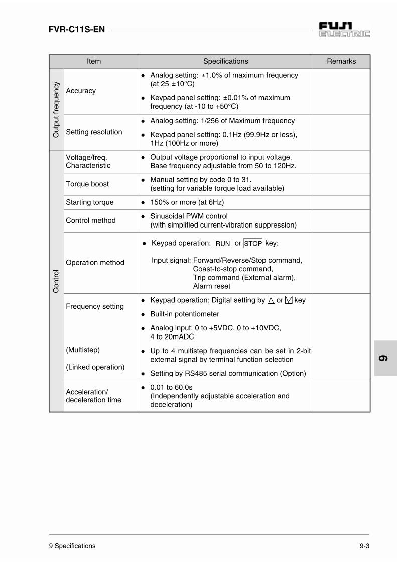
9 Specifications 9-3
FVR-C11S-EN
9
Item Specifications RemarksO
utpu
t fre
quen
cy
Accuracy
Analog setting: 1.0% of maximum frequency(at 25 10°C)
Keypad panel setting: 0.01% of maximum frequency (at -10 to +50°C)
Setting resolution
Analog setting: 1/256 of Maximum frequency
Keypad panel setting: 0.1Hz (99.9Hz or less), 1Hz (100Hz or more)
Con
trol
Voltage/freq.Characteristic
Output voltage proportional to input voltage.Base frequency adjustable from 50 to 120Hz.
Torque boost Manual setting by code 0 to 31.
(setting for variable torque load available)
Starting torque 150% or more (at 6Hz)
Control method Sinusoidal PWM control
(with simplified current-vibration suppression)
Operation method
Keypad operation: or key:
Input signal: Forward/Reverse/Stop command,Coast-to-stop command, Trip command (External alarm),Alarm reset
Frequency setting
(Multistep)
(Linked operation)
Keypad operation: Digital setting by or key
Built-in potentiometer
Analog input: 0 to +5VDC, 0 to +10VDC, 4 to 20mADC
Up to 4 multistep frequencies can be set in 2-bitexternal signal by terminal function selection
Setting by RS485 serial communication (Option)
Acceleration/deceleration time
0.01 to 60.0s (Independently adjustable acceleration and deceleration)

9-4 9 Specifications
FVR-C11S-EN
9
Item Specifications Remarks
Con
trol
Frequency limiter High and low limits can be set for output frequency
between 0 to 100% in Hz
Bias frequency The bias frequency can be set from -100 to +100%
in Hz.
Gain (frequencysetting signal) 5VDC or 10VDC gain can be selected.
Frequency jump control
Jump frequency (3 points) and jump hysteresiswidth (1 point) can be preset.
Restart after momen-tary power failure
Inverter restarts without causing inverter-trip whenpower supply recovers.
PID control PID control function is provided standard.
Enclosure(JEM 1030) IP20
Cooling method Natural cooling for 0.75kW or less.
Fan cooling for 1.5kW or more.
Indi
catio
n
Running, stopped
Output frequency, output current, and PID reference value/feedback value.The CRG lamp is on when the capacitor ischarged.
Program mode Function code and data code
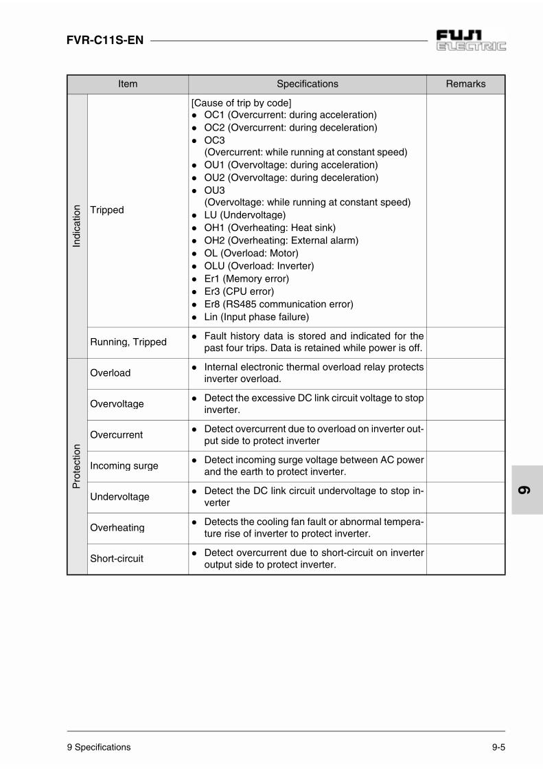
9 Specifications 9-5
FVR-C11S-EN
9
Item Specifications RemarksIn
dica
tion Tripped
[Cause of trip by code] OC1 (Overcurrent: during acceleration) OC2 (Overcurrent: during deceleration) OC3
(Overcurrent: while running at constant speed) OU1 (Overvoltage: during acceleration) OU2 (Overvoltage: during deceleration) OU3
(Overvoltage: while running at constant speed) LU (Undervoltage) OH1 (Overheating: Heat sink) OH2 (Overheating: External alarm) OL (Overload: Motor) OLU (Overload: Inverter) Er1 (Memory error) Er3 (CPU error) Er8 (RS485 communication error) Lin (Input phase failure)
Running, Tripped Fault history data is stored and indicated for the
past four trips. Data is retained while power is off.
Pro
tect
ion
Overload Internal electronic thermal overload relay protects
inverter overload.
Overvoltage Detect the excessive DC link circuit voltage to stop
inverter.
Overcurrent Detect overcurrent due to overload on inverter out-
put side to protect inverter
Incoming surge Detect incoming surge voltage between AC power
and the earth to protect inverter.
Undervoltage Detect the DC link circuit undervoltage to stop in-
verter
Overheating Detects the cooling fan fault or abnormal tempera-
ture rise of inverter to protect inverter.
Short-circuit Detect overcurrent due to short-circuit on inverter
output side to protect inverter.

9-6 9 Specifications
FVR-C11S-EN
9
Item Specifications Remarks
Pro
tect
ion
Ground fault Detects overcorrect due to ground fault on inverter
output side to protect inverter. (Detect at starting)
Motor protection Protect general-purpose motor or FUJI inverter
motor with electronic thermal overload.
Input phase failure protection (only for 3-phase 200V series)
The inverter is protected against phase failure onthe input side or over-current due to inter-phaseimbalance.
Stall prevention
Controls frequency to prevent OC trip in case ofthe output current exceeds the limit value duringacceleration.
Lowers the frequency to hold almost constanttorque in case of the output current exceeds thelimit value during constant speed running.
Controls frequency to prevent OU trip in case ofthe DC link circuit voltage exceeds the limit valueduring deceleration.
Retry "Retry" function can be set for the protective func-
tions OC1 to OC3 and OU1 to OU3.(No. of times of retry: 5, waiting time: 0.5s fixed.)
Dielectricstrength test
At 2000Vac for 1 min. between any main circuitterminals and ground. (10mA or less)
Megger test At 500VDC megger test between any main circuit
terminals and ground (5MΩ or more)
Env
ironm
ent
Installation location Indoor use only. Do not install a dusty location
(Degree of pollution: 2) or expose to direct sunlight, corrosive gases, flammable gases.
Ambienttemperature
-10 to +50°C
Ambienthumidity
5 to 95% RH (No condensation)
Altitude 1000 m or less

9 Specifications 9-7
FVR-C11S-EN
9
Item Specifications RemarksE
nviro
nmen
t
Vibration
3 mm: 2 to less than 9 Hz
9.8m/s2: 9 to less than 20 Hz
2m/s2: 20 to less than 55 Hz
1m/s2: 55 to less than 200 Hz
Storage temperature -25 to +65°C
Storage humidity 5 to 95% RH (No condensation)
Oth
ers
Higher harmonicscurrent suppression
Terminal for connecting power-factor correctingDC reactor (DCR) is provided as standard.
P1, P(+) terminal
Chargingsuppression resistor
Charging suppression resistor is built-in for all in-verter unit.
Cooling fan ON/OFFcontrol
Cooling fan can be automatically stopped when in-verter is stopped.

9-8 9 Specifications
FVR-C11S-EN
9
9-3 Dimensions
Single phase 200V series
TERMINAL 1 30A 30B 30C FM X1 X2 X3 FWD REVP24/CM
11 12 13 C1
TERMINAL 2 G L1/L L2/N P1 P(+)
TERMINAL 3 P(+) N(-) U V W G
Series TypeNominal applied motor
(kW)Dimensions (mm)
D D1 D2 D3 D4
Singlephase200V
FVR0.1C11S-7EN 0.1 80 68.5 27.2 10 43.2
FVR0.2C11S-7EN 0.2 85 73.5 32.2 15 48.2
FVR0.4C11S-7EN 0.4 115 103.5 42.2 25 58.2
FVR0.75C11S-7EN 0.75 140 128.5 67.2 50 83.2
4 - 5 x 6 holes
Detailed diagram for 5 x 6 holeUp/down or right/left symmetry
Terminal 1
4 - 5 x 6 holes
Terminal 3
Terminal 2

9 Specifications 9-9
FVR-C11S-EN
9Single phase 200V series
TERMINAL 1 30A 30B 30C FM X1 X2 X3 FWD REVP24/CM
11 12 13 C1
TERMINAL 2 G L1/L L2/N P1 P(+)
TERMINAL 3 P(+) N(-) U V W G
Series TypeNominal applied motor
(kW)Dimensions (mm)
D D1 D2 D3
Single phase 200V FVR1.5C11S-7EN 1.5 149 137.5 81.2 64
Terminal 2
Terminal 3Terminal 1
Layout of mounting hole1.5C11

9-10 9 Specifications
FVR-C11S-EN
9
Single phase 200V series
TERMINAL 1 30A 30B 30C FM X1 X2 X3 FWD REVP24/CM
11 12 13 C1
TERMINAL 2 G L1/L L2/N P1 P(+)
TERMINAL 3 P(+) N(-) U V W G
Series TypeNominal applied motor
(kW)Dimensions (mm)
D D1 D2 D3
Single phase 200V FVR2.2C11S-7EN 2.2 137 125.5 89.2 72
Terminal 2
Terminal 3Terminal 1
Layout of mounting hole2.2C11S

9 Specifications 9-11
FVR-C11S-EN
9
Table 9-4-1 Peripheral device selection
9-4 Selection of PeripheralDevice
It is recommended to use a prescribed wire according to the EN60204Appendix C.
Pow
er s
uppl
y vo
ltage
Nom
inal
app
lied
mot
or (
kW)
Inverter type
Molded case cir-cuit breaker 1)
(MCCB) Earth-leakagecircuit breaker
(ELCB or RCD)rated current (A)
Magneticcontactor (MC)
Recommended wire size (mm2)
Input circuit Single-phase
200V[L1/L, L2/N]
Outputcircuit
[U,V,W]
Input circuit Single-phase
200V[L1/L, L2/N]
Out
put c
ircui
t 2)
[U,V
,W]
DC
R c
ircui
t 2)
[P1]
[P(+
)]
Con
trol
wiri
ng
Usingwith
DCR.
Notusingwith
reactor.3)
Usingwith
DCR.
Notusingwith
reactor.3)
Usingwith
DCR.
Notusingwith
reactor.3)
Sin
gle-
phas
e 20
0V
0.1 FVR0.1C11S-7EN
66
SC-054)
2.5
4)
2.5 4)
2.5
4)
2.50.5
0.2 FVR0.2C11S-7EN
0.4 FVR0.4C11S-7EN 10
0.75 FVR0.75C11S-7EN 10 16
1.5 FVR1.5C11S-7EN 16 204)
4.0
2.2 FVR2.2C11S-7EN 20 32 SC-5-15)
4.0
5)
6.0
5)
2.5
5)
4.0
1) The frame size and the series for the applicable molded-case circuit breaker(MCCB) and earth-leakage circuit breaker (ELCB or RCD) differ according to thecapacity of transformer in the facility. Refer to each technical document for details.
2) The recommended wire size in the main circuit is for when the ambienttemperature is 40°C and conforming to LVD requirements. The wire size in ( ) isminimum size for IV wire when no necessary of conforming to LVD.
3) Power supply impedance without a reactor must be 0.1% or equivalent byconverting to the inverter capacity. Based on the voltage imbalance, a currentimbalance of 10% is expected.
4) Crimp terminals up to 7.4mm in width (including tolerance) can be used.5) Crimp terminals up to 9.5mm in width (including tolerance) can be used.

10-1 10 Options
FVR-C11S-EN
10
10 Options
Table 10-2-1 External Options
10-1 Built-in Options
There is an optional built-in card for RS485 serial communication.Ask at the inverter distributor for details.
10-2 External Options
Molded case circuitbreaker
The molded case circuit breaker (MCCB) is connected for protecting themain circuit wiring to the inverter and for turning power on and off.The rated current or the rated interrupting capacity varies according to thepower supply specifications.
For input power-factorcorrectingAC reactor (ACR)DC reactor (DCR)
This is connected in the following cases.
1. When the power transformer capacity is more than 500 kVA
2. To reduce input harmonic currentThe input power factor is improved to 0.75 to 0.85 (ACR).The input power factor is improved to 0.9 to 0.95 (DCR).
3. If there is a thyristor load in the same power supply, if the capacitor forpower-factor correcting is turned on or off, or if the surge voltage in thepower supply is large (ACR only)* The DC reactor is unnecessary when the AC reactor is used.
Magnetic contactor (MC)
The inverter can be operated without connecting the magnetic contactor.When the inverter protective function is activated, this should be connect-ed to turn off the power for safety.
Surge absorber This is connected to suppress the surge generated by the exciting coilwhen switching on or off the magnetic contactor and the control relay.S2-A-0 (for magnetic contactor), S1-B-0 (for mini control relay)
Frequencysetting POT(VR)
This is connected when the frequency is set from the control circuit termi-nal using inverter power.

11 Applicable reactors 11-1
FVR-C11S-EN
11
11 Applicable reactors
Table 11-1-1 List of applicable reactors
Connection method
Fig. 11-1-1 Connection method of Input power-factor correcting DC reactor (DCR)
Applicable inverter type Input power-factor correcting DC reactor (DCR)
FVR0.1C11S-7EN DCR2-0.2
FVR0.2C11S-7EN DCR2-0.4
FVR0.4C11S-7EN DCR2-0.75
FVR0.75C11S-7EN DCR2-1.5
FVR1.5C11S-7EN DCR2-2.2
FVR2.2C11S-7EN DCR2-3.7
G
L1/L
L2/N
G
U
V
W
G
P1
P(+)
M3
P1
P(+)
Powersupply Motor
Input power-factor correct-ing DC reactor

FVR-C11S-EN
12-1 12 Compliance with standards
12
12 Compliance with standards
12-1 UL/cUL standards [Applicable to products with UL/cUL mark]
12-1-1 GeneralThe UL standards stand for Underwriters Labo-ratories Inc. and they are safety standards aim-ing at prevention of fire and other accidents inthe United States, thereby providing protectionfor operators, service personnel and other per-sons.The cUL standards are established by UL in theview of compliance with the CSA standards. Theeffect of products certified for the cUL standardsis equal to that of products certified for the CSAstandards.
12-1-2 PrecautionsWhen using the UL/cUL certified product, referto "Compliance with UL/cUL standards" on page2.For connection, refer to Fig. 12-1-1.
Open Type Equipment "indoor use only" Suitable for use on a circuit capable or deliv-
ering not more than 5,000 rms symmetricalamperes, 240V maximum.
When Protected by Class J Fuses. Use 60/75 C CU wire only. A Class 2 circuit wired with Class 1 wire. Field wiring connection must be made by a
UL Listed and CSA Certified closed-loop ter-minal connector sized for the wire gauge in-volved. Connector must be fixed using thecrimp tool specified by the connector manu-facturer.
Solid state motor overload protection is pro-vided in each model.
Fig. 12-1-1 Recommended wiring
G L1/L L2/N P1 P(+)
P(+) N(-) U V W G
M
3~
POWER INPUT FUSE(See instruction manual for rating.)
THRMALOL RY
[THR] [CM]

12 Compliance with standards 12-2
FVR-C11S-EN
12
12-2 Compliance with EMC directive in EU [Applicable to products with CE mark]
12-2-1 GeneralThe CE mark indicated on the FVR-C11S seriesconcerns with European minister directorate di-rective 89/336/EEC concerning the environmen-tal electromagnetic compatibility EMC, and otherdirectives are not included.
The CE mark does not prove that the entire ma-chine or system housing our product complieswith the EMC directive. Therefore indication ofthe CE mark to the entire machine or system willbe done at the responsibility of the manufactureror the machine. This is because:1. The CE mark attached on our product sup-
poses operation of the product under certainconditions. Satisfaction of the conditions is upto the manufacturer of the machine.
2. Generally speaking, various devices are usedin a machine or system as well as our prod-uct. Therefore consideration for the entiremachine or system must be paid by the man-ufacturer of the machine.
The EMC directive includes immunity to the in-coming noise and emission of outgoing noise.The general purpose inverter houses an internalelement switching at a high speed which gener-ates electric noise.
Applicable standardsImmunity: EN 61800-3Emission: EN 61800-3
Above-mentioned "certain conditions" includeinstallation of a dedicated RFI filter in a metalliccontrol panel.Refer to in exclusive Instruction Manual for RFIFilter for details.
12-3 Compliance with low voltagedirective in EU [Applicable to products with TÜV or CE mark]
12-3-1 GeneralThe general purpose inverter is applicable forthe low voltage directive in EU. Compliance ofthe FVR-C11S series with EN 50178/1997 hasbeen obtained from a testing organization in EUand compliance with the low voltage directive isasserted.
12-3-2 PrecautionsRefer to "Compliance with low voltage directivein EU" on pages 2 and 3 when using our productas one complying with the low voltage directivein EU.
FVR-C11S-EN
13-1 13 Electromagnetic Compatibility (EMC)
13
13 ElectromagneticCompatibility (EMC)
13-1 General
In accordance with the provisions described inthe European Commission Guidelines Docu-ment on Council Directive 89/336/EEC,Fuji Electric Co., Ltd. has chosen to classify theFVR-C11S range of Inverters as "ComplexComponents".
Classification as a "Complex Components" al-lows a product to be treated as an "apparatus",and thus permits compliance with the essentialrequirements of the EMC Directive to be demon-strated to both an integrator of FVR Invertersand to his customer or the installer and the user.
FVR Inverters is supplied ‘CE-marked’, signify-ing compliance with EC Directive 89/336/EECwhen fitted with specified filter units installedand earthed in accordance with this sheet.This Specification requires the following per-formance criteria to be met.
EMC product standard EN61800-3/1996
Immunity:Second environment (Industrial environment )
Emission:First environment(Domestic environment )
Finally, it is customer’s responsibility tocheck whether the equipment conforms toEMC directive.
13-2 RFI Filters
It is strongly recommended that the appropriateFVR input filter is used, as shown in the follow-ings, to limit RF current flowing into the mainsupply circuit. Without an input filter a FVR installation may notmeet statutory requirement. FVR Inverters con-tain high-power semi-conductor devices whichare switched at high speeds to synthesize anear-sinusoidal current wave form across thefrequency range of output.Rapidly-changing voltages and currents willgenerate some degree of electromagnetic emis-sion. Emissions will be predominantly conductedthrough the motor and the mains supply cables,although some radiated emissions will be detect-ed in close proximity to the drive system.It is essential that precautions are taken both atthe design stage and at the time of installation toprevent radio frequency interference (RFI) fromthe drive system affecting sensitive equipment inclose proximity.
The RFI filters range are designed especially forthe FVR Inverter and help to ensure EMC com-pliance of machinery and installations using theInverters.The Inverters may be mounted on top of the filterusing the integral fixing positions, the intentionbeing that valuable space inside wiring cabinetsmay be saved. (Refer to Table 13-2-1)

13 Electromagnetic Compatibility (EMC) 13-2
FVR-C11S-EN
13
Table 13-2-1 RFI filters Dimensions
AppliedInverter
Filter TypeRated
Current
Max.Rated
Voltage
DimensionsLxWxH [mm]
MountDims Y x X
[mm]
WiringL’ [mm]
Total1)
Weight [kg]InverterFixings
Fig.
FVR0.1C11S-7ENFVR0.2C11S-7EN
EFL-0.2C11-7 4A
1ph240Vac
180x86x38 155.5x60 125 Approx. 0.7M4 x 12
(4)Fig.
13-2-1
FVR0.4C11S-7ENFVR0.75C11S-7EN
EFL-0.75C11-7 12A 180x86x38 155.5x60 125 Approx. 0.7M4 x 12
(4)Fig.
13-2-1
FVR1.5C11S-7EN EFL-1.5C11-7 20A 190x117x46 165x89 140 Approx. 1.2M4 x 16
(4)Fig.
13-2-2
FVR2.2C11S-7EN EFL-2.2C11-7 29A 240x148x46 216x118 150 Approx. 1.5M4 x 16
(4)Fig.
13-2-2
Note: For detail, refer to the instruction manualthat came with the RFI filters.
Remark: The EMC compliance tests have beencarried out on the basis of theEN61800-3. Measurements weredone with 50m motor cable (EN55011/class A) and 10m motor cable(EN55011/ class B).
Remark: To minimize the conducted radio dis-turbance in the power distribution sys-tem, the length of motor cable shouldbe as short as possible. And it is user’sresponsibility to confirm that the appa-ratus, which the inverters installed in,conforms to EMC directive when long-er motor cable is used or other installa-tion conditions are different from thosedescribed in this manual.
Fig. 13-2-2 RFI FiltersFig. 13-2-1 RFI Filters
Inverterfixingpositions LINE
LOAD
EarthStud
Load wiring toinverter input
Mainsinputterminals
Inverterfixingpositions
LINE
LOAD
EarthStud
Load wiring toinverter input
Mainsinputterminals

13-3 13 Electromagnetic Compatibility (EMC)
FVR-C11S-EN
13
Fig. 13-3-1 Recommended Installation
13-3 Recommended Installation Instructions
It is necessary that these instructions must befollowed to conformed to EMC Directive. Follow the usual safety procedures when work-ing with electrical equipment. All electrical con-nections to the filter, Inverter and motor must bemade by a qualified electrical technician.(Refer to Fig. 13-3-1 and Fig. 13-3-2)
1. Use the correct filter according to Table 13-2-1.
2. Install the Inverter and filter in the electricallyshielded metal wiring cabinet.
3. The back panel of the wiring cabinet of boardshould be prepared for the mounting dimen-sions of the filter. Care should be taken to re-move any paint etc. from the mounting holesand face area of the panel. This will ensurethe best possible earthing of the filter.
4. Use the screened cable for the control , motorand other main wiring which are connected tothe Inverter, and these screens should be se-curely earthed.
5. It is important that all wire lengths are kept asshort as possible and that incoming mainsand outgoing motor cables are kept well sep-arated.
L1/L U V
L2/N W
L L
N NM3
Metal Wiring Cabinet
RCD orMCCB
RFIfilter Inverter
1phPower supply
Screened Motor Cable Motor
Screening must be electricallycontinuous and earthed at the cabinet and the motor.

13 Electromagnetic Compatibility (EMC) 13-4
FVR-C11S-EN
13
Fig. 13-3-2 Recommended installation detail inside the enclosure (SW7 set to P24)
12
V
U
W
13
FWD
11
X1
REV
P24/CM
X3
30C
30B
30A
X2
L1/L
L2/N
P1 P(+) N(-)P(+)
M
FMC1
G
NN
L
G
L
3
When power-factor correcting DC reactor is used.
Metal WiringCabinet
Motor
Power supply1-phase200 to 240V50/60Hz RFI Filter
Frequency setting voltage input(0 to +10VDC)
Frequency setting current input (+4 to +20mADC)
Forward operation command
Reverseoperationcommand
In case of speed control cable,fix a part of shield by a crampas well motor power cable.
Alarm outputfor any fault
To 11 terminal
Analog meter
Analogmonitor
In case of motor power cable, fix a part of shield by a cramp.

FVR-C11S-EN
13

European headquarter:
Fuji Electric GmbH Lyoner Str. 26 D-60528 Frankfurt am Main Tel.: +49-69-66 90 29-0 Fax: +49-69-66 90 29-58e-mail: [email protected]: http://www.fujielectric.de
Germany:
Fuji Electric GmbH Fuji Electric GmbH Fuji Electric GmbH Fuji Electric GmbHHead of sales Sales area Südwest Sales area West Sales area Mitte/NordLyoner Str. 26 Drosselweg 3 Dolmanstr. 46 Lyoner Str. 2660528 Frankfurt am Main 72666 Neckartailfingen 51427 Bergisch Gladbach 60528 Frankfurt am MainTel.: +49-69-66 90 29-47 Tel.: +49-71 27-92 28 00 Tel.: +49-22 04-96 03 88 Tel.: +49-69-66 90 29-47Fax: +49-69-66 90 29-58 Fax: +49-71 27-92 28 01 Fax: +49-22 04-96 03 89 Fax: +49-69-66 90 [email protected] [email protected] [email protected]
Switzerland Italy Spain FranceFuji Electric GmbH Fuji Electric GmbH Fuji Electric GmbH Fuji Electric GmbHZweigniederlassung Centro Direzionale Parc Technòlògic del PERIPARCAltenrhein Viale Colleoni 3, Taurus Vallés-Nr. 023 Immeuble "les NARCISSES"IG-Park I-20041 Agrate Brianza, E-08290 Cerdanyola, 56, rue des Hautes PâturesCH-9423 Altenrhein Milano Barcelona F-92000 Nanterre, ParisTel.: +41-71-8 58 29 49 Tel.: +39-0 39-6 89 03 23 Tel.: +34-93-58 24-3 33/5 Tel.: +33-1-55 66 04-90Fax: +41-71-8 58 29 40 Fax: +39-0 39-6 89 04 46 Fax: +34-93-58 24-3 44 Fax: +33-1-55 66 [email protected] [email protected] [email protected] [email protected]
MGB-C11EN99.9
Subject to technical changes
Solutions for Drives


![3RccRa 3dbW]Rbb 3daRMd...3RccRa 3dbW]Rbb 3daRMd OOO Y^aU §O^bc^] y y FVR \^eRa Wb W] h^da MaRM M]Q cVRh _a^eWQR MZZ cVR bRaeWPRb h^d aR`dWaR Y FVR \^eRa Wb ZWPR]bRQ \ W]bdaRQ M]Q](https://static.fdocuments.in/doc/165x107/5ffe780500e69d7903129655/3rccra-3dbwrbb-3darmd-3rccra-3dbwrbb-3darmd-ooo-yau-obc-y-y-fvr-era.jpg)