From the Instituto de Biofisica, Universidade do Brasil, Rio de Janeiro
38
315 J. Physiol. (I953) II9, 3I5-35I MEMBRANE POTENTIALS IN THE ELECTROPLATES OF THE ELECTRIC EEL BY R. D. KEYNES* AND H. MARTINS-FERREIRA From the Instituto de Biofisica, Universidade do Brasil, Rio de Janeiro (Received 20 August 1952) Ever since Walsh (1773) and Williamson (1775) suggested that the paralysing effect of touching certain fishes was due to an electric discharge, the properties of the electric organ have interested physicists and physiologists alike. It has long been recognized that in most species the electric organ is derived from muscle (Biedermann, 1898), but the exact way in which it has developed has remained in doubt. Several alternative theories have been put forward to explain the mechanism of the discharge (Fessard, 1946), but it has been difficult to decide between them, because the discharge has hitherto been recorded only with externally applied electrodes. Even when fragments of electric organ are used, such experiments cannot reveal the precise site of origin-at the cellular level-of the potential changes. We have therefore applied the type of internal microelectrode first developed by Graham & Gerard (1946), with modifications described by Nastuk & Hodgkin (1950), to investigate the membrane potentials in the individual electroplates of the electric eel, Electrophorus electricus L. Our results, which have already been reported briefly (Keynes & Martins- Ferreira, 1952), show that across both faces of the electroplate there is normally a resting potential of the same size and polarity as that observed in other excitable tissues. During activity a large reversed action potential develops across the innervated face, wbile the potential across the non- nervous face remains virtually unaltered. Preliminary studies of the effects of factors such as the external sodium concentration on the sizes of these potentials suggest that they are produced by mechanisms similar to those responsible for the propagated impulse in nerve and muscle fibres. Considered in conjunction with the recent work of Fatt & Katz (1951 a) on the motor end- plate, our experiments throw some light on the nature of the adaptation which has occurred in the electric organ. * Present address: Physiological Laboratory, University of Cambridge.
Transcript of From the Instituto de Biofisica, Universidade do Brasil, Rio de Janeiro

315
J. Physiol. (I953) II9, 3I5-35I
MEMBRANE POTENTIALS IN THE ELECTROPLATESOF THE ELECTRIC EEL
BY R. D. KEYNES* AND H. MARTINS-FERREIRA
From the Instituto de Biofisica, Universidade do Brasil, Rio de Janeiro
(Received 20 August 1952)
Ever since Walsh (1773) and Williamson (1775) suggested that the paralysingeffect of touching certain fishes was due to an electric discharge, the propertiesof the electric organ have interested physicists and physiologists alike. It haslong been recognized that in most species the electric organ is derived frommuscle (Biedermann, 1898), but the exact way in which it has developed hasremained in doubt. Several alternative theories have been put forward toexplain the mechanism of the discharge (Fessard, 1946), but it has been difficultto decide between them, because the discharge has hitherto been recorded onlywith externally applied electrodes. Even when fragments of electric organ areused, such experiments cannot reveal the precise site of origin-at the cellularlevel-of the potential changes. We have therefore applied the type of internalmicroelectrode first developed by Graham & Gerard (1946), with modificationsdescribed by Nastuk & Hodgkin (1950), to investigate the membrane potentialsin the individual electroplates of the electric eel, Electrophorus electricus L.Our results, which have already been reported briefly (Keynes & Martins-
Ferreira, 1952), show that across both faces of the electroplate there isnormally a resting potential of the same size and polarity as that observed inother excitable tissues. During activity a large reversed action potentialdevelops across the innervated face, wbile the potential across the non-nervous face remains virtually unaltered. Preliminary studies of the effectsof factors such as the external sodium concentration on the sizes of thesepotentials suggest that they are produced by mechanisms similar to thoseresponsible for the propagated impulse in nerve and muscle fibres. Consideredin conjunction with the recent work of Fatt & Katz (1951 a) on the motor end-plate, our experiments throw some light on the nature of the adaptation whichhas occurred in the electric organ.
* Present address: Physiological Laboratory, University of Cambridge.

316 R. D. KEYNES AND H. MARTINS-FERREIRA
METHOD
As Fig. 3 shows, the electric organ is built up of a large number of electroplates,arranged in layers so that the potentials produced during activity are additive.It was difficult to cut slices of electric organ consisting of less than about threelayers of electroplates, so that during the discharge the spaces between thelayers did not remain at the potential of the surrounding fluid. The potentialrecorded between the tip of a single microelectrode and an indifferent non-polarizable electrode was hence not a reliable measure of the membranepotential. We therefore used two microelectrodes which could be manoeuvredindependently, and determined the difference in potential between their tips,with the help of a direct-coupled differential pre-amplifier.
Material
Specimens of Electrophors, varying in length between 0Q4 and 1 m, were obtained from theAmazon region, and were kept at the laboratory in a shallow tank of fresh water. As long as thetemperature was not allowed to fall below about 250C, they survived very well. Each set ofexperiments necessitated the sacrifice of one fish, which was decapitated and then cut up intosegments about 6 cm long. The segments were skinned, and the swimming muscles and Hunter'sorgan (see Fig. 3) were removed, leaving lumps of almost pure electric tissue, which were storedin Ringer's solution at room temperature. Immediately before making the measurements, thesegment was sliced transversely, using a razor blade. The slices were roughly heart-shaped, andabout 5 mm thick.A few of the eels had been given injections of heparin about an hour before decapitation, in order
to provide material for perfusion experiments (Chagas, Couceiro & Martins-Ferreira, 1951) whichwere being done simultaneously. This treatment had no detectable effect on the behaviour of theirelectroplates.
Apparatu8A diagram of the experimental lay-out is shown in Fig. 1. The microelectrodes were attached to
probes containing R.C.A. Type 954 acorn pentodes connected as cathode-followers. One probewas mounted on a Zeiss micromanipulator, and the other on the vertical movement of a modifiedmicroscope stand. The cathode-follower circuit was identical, except for minor differences incomponent values, with that used by Nastuk & Hodgkin (1950). The differential pre-amplifierconsisted of a pair of cathode-coupled triodes (6J7's with screen and suppressor grids strapped tothe anodes), with a pentode (6J7) as the common cathode load. The output from the anode of oneof the triodes was taken via a cathode-follower to the d.c. amplifier of a cathode-ray oscilloscope.The microscope stand was provided with an attachable mechanical stage, fixed at right angles
to the normal position. A Perspex dish was screwed rigidly to the stage. The slices of electric organwere placed in the dish, where they were held between a perforated silver plate and a grid of silverwire stretched across a Perspex frame, which could be lowered on to the slice by means of a smallrack-and-pinion attached to the edge of the dish. Both plate and grid were coated with silverchloride. The dish could be flooded with Ringer's solution, and drained by a suction pump. Thetissue slice was illuminated from below, using a low-power condenser lens, and insertion of themicroelectrodes was observed with a Greenough binocular dissecting microscope on a long-armstand.Square-wave shocks, generated by a Grass electronic stimulator, were applied between the plate
and the grid as shown in Fig. 2. A 4: 1 step-down transformer could be switched into the circuitwhen it was necessary to reverse the polarity of the stimulus. A resistance of 1100 Q) was connectedin series with the plate, in order to make the current effectively constant during the shock, what-ever the resistance of the slice (which was usually between 3 and 15 Qa). It also prevented the slice

POTENTIALS IN ELECTRIC ORGAN
Cathode followerprobe mounted on |
Zeiss Cathode followermicromanipulator I probe mounted on
I| _ e vertical movement\ |@ of microscope
Grid of silverwire on Perspex
frame Microelectrodes
Mechanical Perforated Slice of Perspexstage silver sheet electric rdish
Fixed stage
Illumination
Fig. 1. Diagram of experimental arrangement for recording membrane potentialsin slices of electric organ. Not to scale.
Stimulatorr(utput impedance l
Pulse transformerL2400:600 turns
Upper grid E. . .
Lower sheet L-Slc
317
Fig. 2. Method of stimulating the electroplates. The output from the stimulator could be applieddirectly to the slice when positive pulses were needed, but had to be fed through a transformer(which slightly rounded the leading edge of the shock) when the polarity was reversed.

318 R. D. KEYNES AND H. MARTINS-FERREIRAfrom being short-circuited by the secondary of the transformer. The applied current was mea-sured by observing the potential developed across a monitor resistance of 6-25 LI, whose value(accurate to within 0-15 Q) was subsequently checked against a substandard. A low-resistancevoltage calibrator of the type described by Hodgkin & Huxley (1945) was connected between thesilver grid and earth. Time calibration was provided by a 1 kc/s square-wave generator in theoscilloscope.
SolutionsA Ringer's solution based on the analyses of Electrophoru8 serum made by Hargreaves &
Moreira (1949) was used throughout the work. Its composition is shown in Table 1. The tablealso shows the composition of a sodium-free dextrose solution calculated to be isotonic with theRinger's solution. A similar solution containing 169 m.mole/l. of choline chloride instead of thedextrose was used in some experiments.
TABLE 1. Composition of solutions (m.mole/l.)Electrophorus Ringer
NaCl 169 MgCl2 1-5KCI 5 Na2HPO4 1-2CaCl2 3 NaH2PO4 0-3
Isotonic dextrose solutionDextrose 300 MgCl2 1.5KCI 2-3 K2HPO4 1-2CaCl12 3 KH2PO4 0-3
Microelectrod&sElectrodes whose tip diameter was of the order of 0-5 , were drawn out and filled with 3M-KCI
by boiling at a reduced pressure. They were attached to the probes by short lengths of rubbertubing. Their characteristics were measured by the methods described by Nastuk & Hodgkin(1950). Their series resistance was usually between 4 and 15 M., and the total capacity of theinput stage and microelectrode was of the order of 5 uuF.The main technical problem, which was never fully overcome, lay in finding microelectrodes
which would give a good enough differential balance for transients. For steady potentials, theperformance of the system was very satisfactory, its gain being over 5000 times greater for signalsapplied differentially than for the same signal applied to the tips of both microelectrodes. Fortransients, however, differences in the response times of the two channels, arising almost entirelyfrom inequality of the microelectrode time constants, resulted in the appearance of out-of-balanceartifacts. It was impracticable to improve the balance by adding small capacitances at onecathode-follower grid or the other, since the time constants varied with the depths to which thetips of the electrodes were lowered into the tissue slices. The electrodes were therefore sorted intomatched pairs, but very exact agreement between them could not be demanded without rejectingtoo many. If with a square pulse whose rise time was under 1 psec applied to both electrodes, theartifact was less than 5 % of the output for the same signal fed in asymmetrically, the electrodeswere acceptable; this test ensured that their time constants did not differ by more than 12 %.Since in practice the rates of rise and fall of the membrane potentials were smaller than those ofthe test pulses, this degree of balance was, for most purposes, sufficiently good to avoid seriouserrors. The artifact occurring during the rising phase of the spike was rarely greater than 2 mV,and certainly introduced no significant error into the determination of the height of its relativelyflat peak. Only in investigating the voltage drop in different parts of the slice (see p. 326), wherethe differential balance of the system was more severely tested, would a better performance in thisrespect have been really advantageous.
Experimenta procedureThe slice of electric organ was mounted in the dish, and rinsed with Ringer's solution. The dish
was drained, and a suitable electroplate, i.e. one whose whole surface was exposed without anyvisible damage, was moved under the electrodes by manipulating the mechanical stage. The

POTENTIALS IN ELECTRIC ORGAN 319standard method of recording the potentials when the nervous faces of the electroplates wereuppermost, was as follows: One microelectrode was lowered into the jelly-like extracellularmaterial until its tip was just above the surface of the electroplate. The second microelectrodewas lowered alongside it until the tips were at the same level, and about 150 IL apart. A base-linewas then recorded. The second electrode was next lowered quickly a further 100 u, so as topenetrate into the electroplate. The size of the shock, a square pulse of duration 0-1 or 0-2 msec,was adjusted so that the rising phase of the spike was not obscured by the stimulus artifact, andanother record was taken on the same frame as before. The electrode was finally withdrawn to itsoriginal position, and a third record was made. A number of records were taken with the twoelectrodes in different relative positions, or with the other side of the slice facing upwards, but theprocedure was fundamentally similar.As in other applications of this type of microelectrode (Nastuk & Hodgkin, 1950; Draper &
Weidmann, 1951; Fatt & Katz, 1951 a), a successful penetration was characterized by an abruptchange in the recorded potential as the tip of the electrode entered the cell, and any cases in whichthe potential altered sluggishly were rejected. Sometimes spurious variations in potential, up toabout 20 mV in either direction, were observed while the electrodes were being lowered. Theirorigin was not explored in detail, but they probably arose from the combined effects of gridcurrent and temporary obstruction of the electrode tip (causing a higher series resistance, andhence a positive-going variation in voltage), and from penetration into small nerve fibres in thelayer of nerves, blood vessels, and connective tissue covering the nervous face of the electroplate(see P1. 1). This layer was sufficiently tough to cause the failure of about one penetration in three.Some electroplates were penetrated repeatedly without trouble, but others were only penetratedat the second or third attempt, and a few entirely defied penetration. The connective tissue layerwas almost always considerably dimpled before the electrode passed through it, and it was perhapssurprising that the tips were not often broken in the process. As might be expected, 5 MQelectrodes survived rather better than those with higher resistances and therefore finer tips, but aslong as the shanks were straight and the electrodes were lowered along their own axis, a pair couldgenerally be used for the whole ofan experimental session without any serious decrease in resistanceor visible breakage at the tip.
In experiments on temperature effects, a record was first taken at room temperature, and a rapidflow ofcooled Ringer was then directed on to the surface ofthe slice. After 5 min, the temperaturesof the stream of Ringer, of the surface of the slice, and of the Ringer accumulating in the dishappeared to be the same. The dish was therefore drained, and another record made. After a further5 min wash in Ringer at room temperature, a final record was made. Experiments with sodium-free and potassium-rich solutions were done in a similar way, using longer periods of washing.Sometimes the flow was interrupted for just long enough to drain the dish and make a penetration,in order to observe intermediate stages in the development of the effects. While the solutions wererunning, the electrodes were raised in order to avoid damage to their tips. They were lowered intoa different part of the electroplate for each penetration. It was inadvisable to leave them per-manently lowered during the experiment, owing to the difficulty of allowing for amplifier drifts,and the danger of errors from the diffusion of KCI out of the tips.
Sources of error in the potential measurements(a) The time constants of the microelectrodes and cathode-follower circuits were never greater
than 75pesec. Correction of typical records by the method of subtangent analysis (Lucas, 1912)showed that a time lag of this size would have reduced the amplitude of the recorded spike bymuch less than 1 mV, and would not have had any appreciable effect on its apparent duration.
(b) All records were measured against grids recorded by earthing one cathode-follower input,and increasing the injected calibration voltage in steps of 20 mV up to ±200 mV. The effects ofcurvature of the screen and non-linearity of the amplifier were thus eliminated.
(c) The negative grid current drawn by the cathode-follower tubes was 2 x 10-11 A. This waswell below the level at which it might have introduced measurable errors.

320 R. D. KEYNES AND H. MARTINS-FERREIRA(d) Irreducible mains hum in the oscilloscope amplifier gave some trouble, causing appreciable
vertical scatter in successive traces, and hence discrepancies between the two records of the base-line. In the records taken with the last eighteen eels, the average discrepancy was 1-6 mV. Thissource oferror therefore contributed a standard deviation ofabout ± 1-4 mV to each value obtainedfor the resting potential. In the earlier experiments (using a different oscilloscope) the mains humwas still greater, its contribution being a standard deviation estimated as ±4-0 mV.
(e) The strength of the shock had some influence on the amplitude of the action potential(see p. 332). It is unlikely that the spike size varied by more than ±5 mV over the normal rangeof variation in shock size.
(f) As the microelectrodes were filled with 3M-KCI, the junction potentials between their tipsand the intra- and extracellular material should have been rather small.
(g) Although our microelectrodes were probably somewhat larger at the tip than those used byNastuk & Hodgkin (1950) and Draper & Weidmann (1951), they were not large enough to causeserious short-circuiting of the membrane potential at their point of entry. It was verified that anelectrode of series resistance 0-7 M..Q (whose external tip diameter appeared to be of the order of2-5,u) gave values for resting and action potentials which did not differ significantly from thoseobtained for the same electroplate with a 4 MQ electrode, which was the lowest value normallyused. Nor did 4 and 10 MQl electrodes give different results. An even blunter electrode (5 at thetip) gave the same action potential on being pushed right through the electroplate, but would notgive a satisfactory indication of the resting potential. Attempts were made to see whether theresting potential recorded with one microelectrode was reduced when another electrode wasinserted close by, but these failed because of movements of the electroplate while the secondelectrode was being pushed through the layer of nerve fibres and connective tissue.
(h) The recorded spike must have been slightly reduced by the voltage drop across the intra-and extracellular material due to current flowing during the discharge (see p. 326). In penetratingthe nervous face the microelectrode was generally lowered about l00,u, which would cause a lossof 2-7 mV (using the mean values given in Table 2). This estimate does not take into account theloss across the nervous face itself, which cannot easily be calculated. A spike current of 4-6 mA/cm2(see Table 2) flowing through the resting membrane resistance of 7-40 cm2 (see p. 333) wouldresult in a loss of 34 mV, but a forty-fold drop in membrane resistance during activity, as wasobserved for squid axons by Cole & Curtis (1939), would reduce the effect to under 1 mV. Directevidence that the voltage drop effect did not introduce large errors was obtained on one occasionby seeing whether the spike was affected by short-circuiting the protective resistance in series withthe transformer secondary (see Fig. 2). As the output impedance of the stimulator was 500 Q, thisloaded the slice with a resistance of 500/42, or 31 Q2. Assuming the slice to have been 3 cm2 in area,and four electroplates thick, so that its total discharge was 600 mV, the extra current drawnmust have been of the order of 6 mA/cm'. Nevertheless, the change in spike size was certainlyunder 1 mV.
(i) The electroplates chosen for penetration were always, as far as could be seen, intact andundamaged. In freshly prepared slices it was found that the electroplates which had been cutthrough at some point tended to give spikes which were smaller and shorter than normal; 1 mmfrom the cut end the resting potential was reduced to about half and the electroplate wasinexcitable. When the condition of an electroplate deteriorated rapidly in the course of anexperiment, the results were rejected, but they were often observed only over a short period, andit is probable that some slightly damaged electroplates passed undetected.
(j) From the scatter of the results in experiments where at least two separate penetrationswere made into the same electroplate, the average standard deviation for a single penetrationcould be calculated. In twenty cases (for the last eighteen and not the first ten eels), it was±3-6 mV for the resting potential, and ±4-3 mV for the action potential. There may thereforehave been significant sources of variation other than those already listed, and perhaps genuinesmall differences in the membrane potentials at different points along the surface.

POTENTIALS IN ELECTRIC ORGAN 321
THE ANATOMY OF THE ELECTRIC ORGAN
It is necessary to describe very briefly the relevant anatomical features of theelectric organ. For a fuller account, Biedermann (1898) and Couceiro &Akerman (1948) should be consulted. The electric tissue occupies most of theposterior four-fifths of the fish, as is indicated in Fig. 3. It is divided into threeparts-the main organ, Hunter's organ, and the organ of Sachs. Each organ
A B
Main Hunter's Organorgan organ of Sachs
Section / Swimming musclesatAAFa
at___ Spinal cordSwim bladder
Main organ
Muscle
Hunter's organ
Part of E1030mm->section . $c. 1 mmat B l Organ of Sachs
(electroplates widely spaced)Main organ
(electroplates closely spaced)
Fig. 3. Highly diagrammatic representation of the anatomy of the electric organ in Electrophoru8electricu8. The lower section, drawn in perspective, shows how the electroplates (whose faceslie in the plane of the paper) are arranged in columns.
is built up of a large number of electroplates, stacked in columns runningparallel to the spinal cord, so that during activity a potential difference isdeveloped between the head and tail ofthe eel. The individual electroplates are,very roughly, lOO,u thick (in the longitudinal or antero-posterior direction),1 mm wide (in the transverse or tangential direction), and 10-30 mm long(in the radial direction). In the main organ they are packed very closelytogether, but in the organ of Sachs they are spaced some distance apart, andthe uppermost electroplates near the tail may have extracellular gaps over2 mm wide (in the longitudinal direction) separating them. The photomicro-
PH. CXIX. 21

R. D. KEYNES AND H. MARTINS-FERREIRAgraphs in Pl. 1, for which we are indebted to Dr A. Couceiro, show theappearance of the electroplates in sections cut vertically, parallel to the spinalcord. It can be seen that the afferent nerves and blood vessels are distributedonly to the posterior faces of the electroplates, where the nerves terminate inendings on numerous small papillae which cover the whole surface. Theanterior faces are studded with large irregularly shaped papillae, which projectinto the jelly-like extracellular material which fills the spaces between theelectroplates. In the organ of Sachs the electroplates are somewhat wider,and the papillae are larger than in the main organ, but their structure isotherwise very similar.The microelectrodes were lowered vertically on to the surface of slices cut
perpendicular to the longitudinal axis of the fish. They thus penetrated theelectroplates at right angles to the nervous faces. For good results it wasessential to choose electroplates whose whole surface was exposed, but whichhad not been harmed in cutting the slice. This criterion could never besatisfied in slices cut from the main organ, owing to the close packing of theelectroplates, but in a slice cut from the organ of Sachs there were generallya few electroplates suitably exposed. Almost all the experiments describedhere were therefore done with electroplates from the organ of Sachs. In fact,they owed much of their success to the convenient anatomy of this part of theelectric organ.
RESULTS
The membrane potentials in an electroplateFig. 4 shows the potentials recorded when a microelectrode was lowered intoan electroplate through the nervous (posterior) face, and then withdrawn.Record A was taken with both microelectrodes at the same level just abovethe electroplate, providing a base-line (with a superimposed stimulus artifactcaused by the imperfect differential balance of the two channels for transients).Record B was then taken with one electrode lowered about 100,u so as topenetrate into the electroplate. As in a nerve or muscle fibre, the inside of thecell was about 85 mV negative with respect to the outside. Stimulationresulted in an action potential of about 150 mV, at the peak of which themembrane potential was reversed in the manner characteristic of many otherexcitable tissues (Hodgkin, 1951). On raising the electrode to its originalposition, record C was obtained, this being coincident with A except fora slight sideways displacement arising from random variation in time delaybetween the time-base synchronizing pulse and the stimulus.Another series of records taken with the same electroplate is illustrated in
Fig. 5. For records A and B, the two microelectrodes were in the samerelative positions as before, but for C one of them was pushed right throughthe electroplate so as to emerge into the extracellular space below it. With thetips of the two electrodes thus on opposite sides of the electroplate, no steady
322

POTENTIALS IN ELECTRIC ORGAN
-I
-401
-80
-120
ACl\
1- 'I
B
I I I l I l I I I msecA B C
Fig. 4. Membrane potentials in an electroplate from the organ of Sachs, recorded by approachingthrough the nervous face. In the diagram of the stylized electroplate below, which shows therelative positions of the microelectrodes for the three records A, B and C, the non-nervous
(anterior) face is drawn with large papillae. Temperature 270 C.
+160
+120
+80
±40
-1201 I I I I I I I I ImsecA B C
Fig. 5. Another set of records of the membrane potential in the same electroplate as Fig. 4.For the final record (C) the microelectrode was lowered one stage further than before, so asto transfix the electroplate and emerge into the extracellular space beneath the non-nervouaface.
21-2
323
+80 _MV
+40 -

R. D. KEYNES AND H. MARTINS-FERREIRA
potential difference was recorded, but the action potential was almost thesame size as it was across the nervous face alone (record B). It follows that theresting potentials across the two faces must have been equal, and that therewas little or no action potential across the non-nervous face.
This conclusion is borne out by Fig. 6, which shows the result of invertinga slice of electric organ, and penetrating the electroplate from the otherdirection-through the non-nervous (anterior) face. Again the restingpotential appeared when one electrode was inside and the other outside the
+40 -mV
A
C-40 -
B-80
-120
-160
| msecA 8 C
Fig. 6. Membrane potentials recorded by penetrating the non-nervous face of an electroplate.The action potential does not appear until the electroplate is transfixed (record C).Temperature 230 (not the same eel as Figs. 4 and 5).
cell, and disappeared when both were outside. During activity there wasalmost no potential change across the non-nervous face (record B), the actionpotential only being recorded, now upside-down in comparison with Fig. 4,when the tip of the movable electrode was beneath the electroplate(record C).Examination of all the records in which electroplates had been transfixed
by a microelectrode confirmed that there was generally no appreciable netpotential difference across them. In one record the lower side of the electro-plate was apparently 20 mV negative with respect to the upper side, but thiswas probably caused by a spurious shift of the base-line, and in the otherrecords the figure rarely exceeded + 6 mV. The average potential differenceacross the electroplates did not differ significantly from zero, since in twenty-one cases where the nervous face was uppermost, the lower side was negativeby only 08 + 1-3 mV (S.E. of mean), and in a further twenty-one records takenwith inverted slices it was 1-2 + 0-8 mV negative. It would not really have
324

POTENTIALS IN ELECTRIC ORGAN 325
been surprising if there had been a small potential across the electroplates,since whichever way the slices were orientated, their upper surfaces werebathed with Ringer's solution, in which the ionic concentrations may nothave been exactly the same as in the extracellular spaces of the tissue.A diffusion potential might, therefore, have developed across the top electro-plate. This effect was observed in a few experiments where the Ringer'ssolution was modified (see below), but evidently caused no easily measurablepotentials under normal experimental conditions. It is justifiable to concludethat the resting potentials across the nervous and non-nervous faces of theelectroplate were equal to within experimental error.
A. At rest Tail B. At the peak ,of the spike ,'
A~~~~~~~~~~~~~~~~~~~~~~~~~~~~~~~~~~I
+ + + + 67 - - -- - ~~~~~84+7+-:
+ ~9~ + + 84 84 +
A AIV
+ + + 7 - -
++ + + ~~~84847 + + + +
Current flow lwhich produces /direct response _ _
Head Current flow
during discharge
Fig. 7. Diagram illustrating the additive discharge of the electroplates. At rest (A) there is nonet potential across the electroplates, but at the peak of the spike (B) all the potentials arein series, and the head of the eel becomes positive with respect to its tail. The figures are theoverall averages obtained for electroplates in the organ of Sachs.
The voltage drop within the slice
It may be noticed in Fig. 5 that the action potential recorded across thewhole electroplate (record C) was slightly smaller than it was across the nervousface alone (record B). This was often observed, the mean value of the differencein size of the action potential being 5-5 + 1-2 mV (twenty-one records; forwhich a significance test gives P <0.001). The discrepancy could be explainedin two ways. There might be an action potential of this magnitude across thenon-nervous face, as record B in Fig. 6 may suggest. Or, as the diagram inFig. 7 shows, current flowing during the discharge might produce a voltage

R. D. KEYNES AND H. MARTINS-FERREIRA
drop across the intra- and extracellular material and across the passiveresistance of the non-nervous face, which would offset the recorded actionpotential when the tip of one electrode was much above the other.An attempt was made to discriminate between these two possibilities by
investigating the contribution of the voltage drop effect. With increasedamplifier gain, the vertical voltage drop in different parts of the slice could bedetermined by setting one electrode a known distance (generally 50 or 100,)above the other, and then measuring the potential difference developed betweenthem during the spike. The wave-form of the pulse thus recorded was some-times rather complex, owing to the poor transient balance of the recordingsystem, but reasonably consistent results were obtained by measuring thepotential only at the point corresponding in time to the flat-topped peak ofthe action potential. Whenever the non-nervous face lay between the twoelectrodes (as indicated by a change in resting potential), the recordedpotential drop was slightly larger than for a corresponding depth of intra-or extracellular material. The difference gave a measure of the drop across thenon-nervous face itself. A similar set of measurements was made with a shortpulse of constant current flowing through the slice in the direction opposite tothat which stimulated the electroplates. Knowing the size of the appliedcurrent and the area of the slice, and assuming that the current was distributeduniformly across the slice, the effective resistances of the cytoplasm of theelectroplate, of the extracellular material, and of the non-nervous face, couldnext be calculated. Comparison of the voltage gradient for the spike and forthe known constant current, across the same part of the slice, gave a figure forthe current flowing during the spike. This was then multiplied by the resistanceof the non-nervous face, in order to obtain the expected value of the voltagedrop across it, if there were no active potential change.The results of several experiments of this type are given in Table 2. There
was apparently considerable variation in spike current, though some of this mayhave been due to experimental error, since the voltages were too small to bemeasured with great precision, and it was uncertain how far the assumption ofuniform current distribution was justified. Nevertheless, the figures obtainedfor the specific resistances inside and outside the electroplates were fairlyself-consistent, and fitted reasonably well with the specific resistance of theRinger, which was calculated to be about 50 Q cm at 250 C. Overan appreciablerange of absolute sizes, the observed and calculated values of the voltage dropacross the non-nervous face agreed rather well, neither of them being con-sistently smaller or greater than the other. This provides good evidence thatthere was no active potential change across the non-nervous face.
The results of two more incomplete experiments, omitted from Table 2, indicate that theintracellular specific resistance may not really be lower than the extracellular resistance, asTable 2 suggests. However, the cytoplasm of the electroplates does appear to be similar to the
326

POTENTIALS IN ELECTRIC ORGANaxoplasm of frog myelinated nerve fibres in having an electrical resistance nearly equal to that ofthe body fluids, whereas other invertebrate nerves and frog muscle have relatively high internalresistances (Huxley & Stampfli, 1951).
TABLE 2. The voltage drop across the non-nervous face of the electroplateduring the action potential
Voltage dropSpecific resistance Resistance in non-nervous face
Size , Spike of non- -
of spike Intracellular Extracellular current nervous face Calculated Observed(mV) (a cm) (Q cm) (mA/cm2) (Qcm2) (mV) (mV)145 55 77 3-6 0-13 0-46 0-76161 39 33 2-0 0-08 0-16 0 03136 38 50 13-9 0-26 3-6 2-7145 55 83 2-6 0-38 1.0 1-2139 66 97 1.0 0-29 0-3 0 4Mean 51 68 4-6 0-23 1.1 1-0
In most of the experiments, no record was kept of the actual amounts bywhich the electrodes were moved in order to penetrate the electroplates.However, the movements were certainly of the right order for the voltage dropeffect to account both for the slight reduction in size of the spike when theelectroplate was transfixed from the nervous side, and for the small positive-going change in membrane potential during the spike which is visible inFig. 6, record B. Taking the average values from Table 2, a loss of 5-5 mV(see above) would correspond to lowering the electrode about 160i. Intwenty-one penetrations through the non-nervous face (as Fig. 6), the meanapparent decrease in resting potential during the spike was 4-2 + 1-0 mV,which could be caused by a movement of 11O,t.The diagram in Fig. 7 summarizes the facts described so far, and shows how
the additive discharge of a column of electroplates is achieved. In the restingstate there is no net potential across the electroplates, however many areconnected in series. During activity, the reversed potentials across thenervous faces are added to the unaltered potentials across the non-nervousfaces, and each electroplate therefore contributes a voltage equal in size to itsaction potential.
Potentials in different parts of the electric organThe organ of Sachs. Table 3 gives the mean values of the resting potential,
of the action potential, and of its duration (measured at half the peak ampli-tude) in all the eels for which at least four different electroplates were pene-trated through the nervous face. The corresponding figures for a furthereleven eels, in each of which not more than three records were obtained, were:R.P. 82 mV, A.P. 146 mV, and duration 2-2 msec. Averaging the two sets offigures, and allowing for the fact that the spike was reduced about 3 mV belowits true size by the voltage drop effect (see p. 320), the best overall estimatefor the membrane potentials in the organ of Sachs at 24° C was: R.P. 84 mVY
327

R. D. KEYNES AND H. MARTINS-FERREIRAA.P. 151 mV, and duration 2-3 msec. The averages for penetrations throughthe non-nervous face (also in eleven eels)-R.P. 83 mV, A.P. 141 mV, andduration 2-0 msec--agreed well, since the total correction for the voltage dropeffect was about 7 mV when recording in this fashion. The table shows thestandard error of each figure, and it is clear that there was some significantvariation from one eel to another. However, the variation in membranepotentials was not very extensive, and it was only the durations which differedappreciably between individual fishes. Part of the variability in duration wasprobably caused by temperature differences; taking its Qlo as 2f5 (see below),and correcting all the results to 240 C, the range of durations in all twenty-twoeels was reduced to 1F4-3f1 msec.
TABLE 3. Average sizes of resting and action potentials in electroplates of Sachs's organ
Resting ActionEel Temp. No. of potential potential Overshoot Durationno. (O C) records (mV) (mV) (mV) (msec)7H 2: 4 88±1 145±3 56±3 2-1 ±0058 21 4 100 ±2 158 ±5 59 ±510 24 4 82 ±2 152 ±8 70 ±512 23 6 82 ±2 151 ±5 69 ±4 2-2 ±0-1614 24 13 88 ±1 155 ±3 68 ±2 17 ±0-0515H 24 17 88 ±2 154 ±3 66 ±2 2.9 ±00919 22 7 88 ±2 153 ±3 64 ±2 3-7 ±0-1620H 23 5 81 ±1 152 ±3 72 ±2 2-9 ±0-1821 24 15 76 ±2 137 ±3 61 ±2 2-2 ±0 1127 27 5 90 ±4 144 ±4 54 ±4 1.3 ±0 0328 25 5 83 ±4 152 ±8 69 ±4 25 ±0-12
Mean 24 86 ±1 9 150 ±1-8 64 ±1-8 2-4
All these measurements were made by penetrating the electroplate through the nervous face.For the first six eels, non-standard techniques were used, and the results were rejected altogether.Eels marked H bad been injected with heparin before starting the experiment. The duration wasmeasured at half the peak amplitude of the action potential. Standard errors of the means for eacheel are given, and also the standard errors of the overall means (which are not weighted).
The greatest action potential recorded in any electroplate was 180 mV inthe first electroplate of eel no. 14 to be penetrated; its resting potential was90 mV. This may seem a surprisingly large value, but there was no reason todoubt its genuineness, and most of the possible errors in determining it wouldhave made it too small rather than too large (see 'Method'). This recordwas made sooner after the death of the fish (about 20 min) than any otherin the whole series, and it is conceivable that there was a sharp initial declinein the size of the spike, which thereafter remained steady for some time. Eelno. 14 gave a mean of 168 + 5 mV (four records) 0-5 hr after decapitation,and 153 + 1-7 mV (four records) some 3-3 hr later (which is a significant change,P=0-03). The fall in action potential with time was sometimes greater thanthis, and sometimes there was less change (eel no. 15H gave 159 + 4 mV infour of its electroplates 0-5 hr after decapitation, and precisely the sameresult in another four penetrations made 3-7 hr later).
328
POTENTIALS IN ELECTRIC ORGANIn any given slice through the organ of Sachs there was always appreciable
variation in the longitudinal spacing of the electroplates. In a large eel, forinstance, the distance between the electroplates might be 2-3 mm in theupper part of the organ (nearest the spinal cord), and only 0O8 mm in thelowest part, with intermediate spacings in between. It seemed possible thatthere would be some correlation between spacing and size of action potential,but no convincing evidence was obtained that the size of the spikes was relatedto the position of the electroplates. Nor was there any obvious connexionbetween the total area of the electroplates and their spike size. These questionswere not investigated thoroughly enough for the existence of such correlationsto be ruled out, but it was quite clear that any variations in action potentialwere much smaller than the variations in spacing and in area. If all theelectroplates discharge simultaneously, there must be marked discrepanciesbetween the voltages generated by different regions of the electric organ, anda rather complicated pattern of current flow within it.The main organ. Once the technique of penetrating the electroplates in the
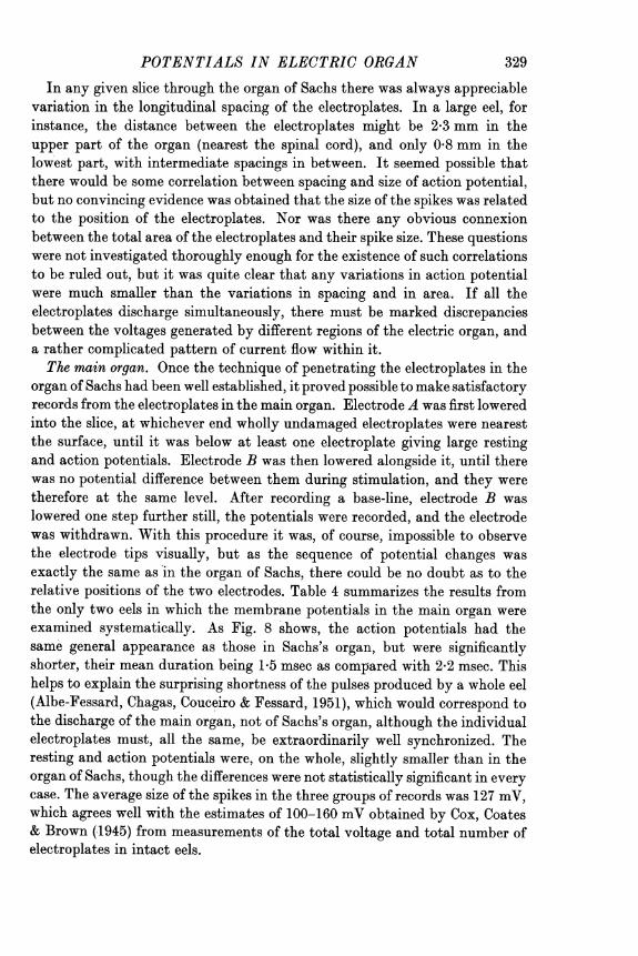
organ of Sachs had been well established, it proved possible to make satisfactoryrecords from the electroplates in the main organ. Electrode A was first loweredinto the slice, at whichever end wholly undamaged electroplates were nearestthe surface, until it was below at least one electroplate giving large restingand action potentials. Electrode B was then lowered alongside it, until therewas no potential difference between them during stimulation, and they weretherefore at the same level. After recording a base-line, electrode B waslowered one step further still, the potentials were recorded, and the electrodewas withdrawn. With this procedure it was, of course, impossible to observethe electrode tips visually, but as the sequence of potential changes wasexactly the same as in the organ of Sachs, there could be no doubt as to therelative positions of the two electrodes. Table 4 summarizes the results fromthe only two eels in which the membrane potentials in the main organ wereexamined systematically. As Fig. 8 shows, the action potentials had thesame general appearance as those in Sachs's organ, but were significantlyshorter, their mean duration being 1-5 msec as compared with 2-2 msec. Thishelps to explain the surprising shortness of the pulses produced by a whole eel(Albe-Fessard, Chagas, Couceiro & Fessard, 1951), which would correspond tothe discharge of the main organ, not of Sachs's organ, although the individualelectroplates must, all the same, be extraordinarily well synchronized. Theresting and action potentials were, on the whole, slightly smaller than in theorgan of Sachs, though the differences were not statistically significant in everycase. The average size of the spikes in the three groups of records was 127 mV,which agrees well with the estimates of 100-160 mV obtained by Cox, Coates& Brown (.1945) from measurements of the total voltage and total number ofelectroplates in intact eels.
329
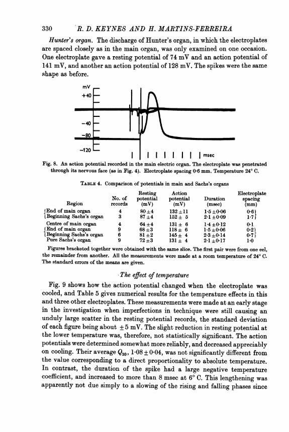
R. D. KEYNES AND H. MARTINS-FERREIRAHunter's organ. The discharge of Hunter's organ, in which the electroplates
are spaced closely as in the main organ, was only examined on one occasion.One electroplate gave a resting potential of 74 mV and an action potential of141 mV, and another an action potential of 128 mV. The spikes were the sameshape as before.
mv+40 _r
-120
-120 l |||msecFig. 8. An action potential recorded in the main electric organ. The electroplate was penetrated
through its nervous face (as in Fig. 4). Electroplate spacing 0-6 mm. Temperature 24° C.
TABLE 4. Comparison of potentials in main and Sachs's organs
Resting Action ElectroplateNo. of potential potential Duration spacing
Region records (mV) (mV) (msec) (mm)JEndofmainorgan 4 80±4 132±11 15±0-06 0-61(Beginning Sachs's organ 3 87 ±4 152 ± 5 241 ±0 09 1 7Centre of main organ 4 64 ±4 131 + 6 1 4 ±012 041End of main organ 9 68 ±3 118 ± 6 1.5 ±0-06 0 21{Beginning Sachs's organ 6 81 ±2 145 ± 4 2*3 ±0*14 0 7Pure Sachs's organ 9 72 ±3 131 ± 4 2-1 ±017 1.0Figures bracketed together were obtained with the same slice. The first pair were from one eel,
the remainder from another. All the measurements were made at a room temperature of 240 C.The standard errors of the means are given.
The effect of temperatureFig. 9 shows how the action potential changed when the electroplate was
cooled, and Table 5 gives numerical results for the temperature effects in thisand three other electroplates. These measurements were made at an early stagein the investigation when imperfections in technique were still causing anunduly large scatter in the resting potential records, the standard deviationof each figure being about + 5 mV. The slight reduction in resting potential atthe lower temperature was, therefore, not statistically significant. The actionpotentials were determined somewhat more reliably, and decreased appreciablyon cooling. Their average Qlo, 1.08 + 0*04, was not significantly different fromthe value corresponding to a direct proportionality to absolute temperature.In contrast, the duration of the spike had a large negative temperaturecoefficient, and increased to more than 8 msec at 60 C. This lengthening wasapparently not due simply to a slowing of the rising and falling phases since
330

POTENTIALS IN ELECTRIC ORGAN 331the maximum slopes had rather smaller Q1o's than the duration. Hodgkin &Katz (1949) reported similar temperature effects for squid axons, where thesizes of the potentials did not vary much, and the rate of restoration of theresting potential at the end of the spike had the largest Qlo.
mV+80 - - - --- - - - - - - - - - - - - - - - - -
+40 - - - - - - - - - - - -
-0
-40 - - - - -A-80 __ __ A \
I I I I I I I I I I I I I I Imsec-120 - - - - - - - -
- - - - - - - - - - -
Fig. 9. Superimposed tracings showing the effect on the action potential of cooling the electro-plate. Curve A is drawn as the mean of potentials recorded through the nervous face (as inFig. 4) at 21.50 C, before and after cooling. The two values for the resting potential were 88and 80 mV respectively, and the spikes were virtually identical. Curve B was recordedat 7.50 C.
TABLE 5. The effect of temperature on the membrane potentials
Maximumrate (V/sec)
Resting Action of Q10Temp. potential potential Duration , Ax I
(O C) (mV) (mV) (msec) Rise Fall A.P. Duration Rise Fall23 80 5 143 1-7 251 143 1-03 2-33 1-50 1-59{12 80 138 4X3 160 8622 91-5 134-5 2-0 158 120 1 11 2-41 1-60 1-73
{ 6 83 115 8-2 75 5021 91-5 140-5 2-3 179 108 1-17 2-52 - 2-04
l11 89 120 5-8 - 5321-5 84 148-5 2-15 188 172 1*01 2-64 1-43 1-81
l 7-5 84 146 8-4 114 75Mean 22 88 142 2-0 194 136 1-08 ± 2-48 ± 1-51 179±
0*04 0-07 0-05 0-09Each figure at the upper temperature is the mean of two measurements, made before and after
cooling. Durations were measured at half the peak amplitude. Maximum rates of rise and fallwere measured graphically from the action potential records. In one case the stimulus artifactobscured too much of the rising phase for the rate of rise to be measured. The standard errors ofthe mean Qlo's are given.
Excitation of the nervous faceThe electroplates in slices of electric organ from Electrophorus can be
stimulated in two ways-either directly, with a latency often under 0 1 msec,or indirectly, through stimulation of the nerve endings, with a latency of at

R. D. KEYNES AND H. MARTINS-FERREIRA
least 1-5 msec (Albe-Fessard, Chagas & Martins-Ferreira, 1951). The directresponse was used in all our experiments, this being elicited by brief pulses ofcurrent passed through the slice in the antero-posterior direction, but notby the flow of current in the opposite direction. We did not perform anycritical experiments on the mechanism of excitation in the electroplates,although the type of technique evolved would be suitable for further investi-gation of this very interesting question. But we made a few relevant observa-tions, largely qualitative in nature, which are worthy of mention here.
It will be obvious on referring to Fig. 7 that the current which caused directexcitation was that which depolarized the nervous face of the electroplate.This mode of stimulation was thus analogous to the usual method of stimu-lating a nerve or muscle fibre by applying a cathode externally. The analogy
100 100mV A m
_
I I I I I I msec I I I msec
Fig. 10. Superimposed tracings of the responses of an electroplate when the size of stimulus wasvaried, recorded through the nervous face. The figures show relative shock strengths.A, 0-02 msec shock, threshold about 17 mA/cm2. B, 1-2 msec shock, threshold about1-5 mA/cm2. Temperature 250 C. In each case both types of response at threshold wererecorded without touching the shock strength control.
extended somewhat further, since the nervous face responded in a characteristicall-or-none fashion, as may be seen in Fig. 10, which shows the effect of varyingthe stimulus strength, for pulses 0-02 and 1-2 msec in duration. As the spikearose from synchronous (or almost synchronous) activity of the whole surfaceof the electroplate, the main features of these records should be compared withthose of the non-propagated membrane action potentials obtained in squidaxons by Hodgkin, Huxley & Katz (1952), rather than with normal pro-pagated action potentials. The stimulus strength could be set at a level wherethe electroplate sometimes gave a subthreshold response resembling the localresponse observed in many other excitable tissues, and sometimes, after a delayof several milliseconds, a full-sized spike. By applying a larger shock, thedelay could then be reduced virtually to zero without much change in theappearance of the spike. However, the all-or-none law was often not perfectlyobeyed, since the spike showed a tendency, particularly when the electroplateseemed to be in poor condition, to be slightly smaller and shorter close tothreshold. This effect cannot have arisen from distortion of the record by the
332

POTENTIALS IN ELECTRIC ORGAN
stimulus artifact, since by the time the peak of the spike was reached, theartifact was very small. It may possibly have been a consequence of thecomplex folding and corrugation of the electroplate surface, which must haveresulted in a non-uniform distribution of the stimulating current, and henceincomplete excitation of the membrane at threshold. But if this idea werecorrect, it appears likely that the threshold response would be asynchronous,and therefore lengthened, instead of being shorter, as Fig. 10 shows it to be.For the present, the departures from ideal all-or-none behaviour must be leftunexplained.
Using shocks over 10 msec in duration, the average voltage drop producedacross the nervous face at threshold was measured, and found to be 11-4 mV(mean of seven observations ranging from 10 to 13 mV). The correspondingcurrent was 1-65 mA/cm2, and 1-0 mV was subtracted from the observedvalues to allow for the voltage drop across 100t of extra- and intracellulartissue (see p. 327). This figure is comparable with the critical depolarizationof 12-15 mV necessary to excite the squid axon membrane (Hodgkin et al.1952). When shorter shocks were used, the initial depolarization required atthreshold was considerably greater, as may be observed in Fig. 10. When theshock was very long (20 or 50 msec), repetitive responses were sometimesobtained as soon as the depolarization exceeded the critical value.On several occasions the indirect response was elicited, in order to see how it
compared with the direct response. Fig. 11 shows a typical picture of thedirect and indirect responses in the same electroplate. In confirmation ofAlbe-Fessard, Chagas & Martins-Ferreira (1951), it was noted that theindirect response required longer and larger shocks, that it arose with anirreducible latency of about 1-5 msec, that it was more easily fatigued (sliceswhich had been maltreated, or left to soak in Ringer's solution for long periods,sometimes gave an almost unimpaired direct response when they would giveno indirect response at all), and that it showed marked facilitation effects(it was most easily obtained by stimulating at a repetition rate of at least30/sec). No initial steps of the type recorded by Fatt & Katz (1951 a) nearmotor end-plates in frog muscle were ever seen, but no serious effort was madeto search for end-plate potentials, and it is possible that they might have beenfound if nerve-organ preparations had been used, and if trouble had beentaken to insert one of the microelectrodes close to a nerve ending.
Membrane characteristic8The effective resistance of the nervous face was determined in a number of experiments similar
to (but often less complete than) that described on p. 326, i.e. by measuring the steady componentof the voltage drop across it when pulses of current were applied to the slice. The average resultwas 7-4 Ql cm2 (eleven values ranging from 4-1 to 12-8 acm2). Most of the measurements weremade with 1 msec pulses of current flowing in the posterio-anterior direction, the currentdensities being between 1 and 7 mA/cm2. On several occasions the voltage drop was also measuredwith just subthreshold currents flowing in the reverse direction. No evidence was found of
333

334 R. D. KEYNES AND H. MARTINS-FERREIRAany rectification effects, the membrane resistance being the same to within experimental errorfor currents up to about 1-5 mA/cm2 flowing in either direction. In cases where the specificresistance of the cytoplasm and extracellular material was not determined at the same time, acorrection of 0 6 Q2cm2 was subtracted from the result, in order to allow for a vertical distance of100j between the electrode tips (and a mean specific resistance of 60 Q2cm, from Table 2). Therewere two further sources of error for which reliable compensation could not easily be made, butwhich tended to cancel one another out. One was the presence of connective tissue septa betweenthe columns of electroplates, which occupied about 10 % of the total area, and which probably
mV+80
0
-40-
-80-
-120 -
-160
I I I I I I I I I nmsecFig. 11. Superimposed tracings of direct and indirect responses for an electroplate in the tail end
of Sachs's organ, recorded through the nervous face. A, direct response, 0-1 msec shock,cathodal, about 1/sec; B, indirect response, 1 msec shock, anodal, 30/sec; C, direct response,0-1 msec shock, cathodal, 30/sec. Strength of shock the same in each case. Temperature230 C. C was recorded last, and the spike was probably somewhat reduced by fatigue anda rise in threshold. The hump on the descending phase of the indirect response (B) was notalways seen, and in some other records the direct and indirect responses were exactly thesame in size and in duration.
had a higher specific resistance than the rest of the slice. The other was the existence of short-circuits within the slice, which allowed a mean current of 4-6 mA/cm2 to flow during the spike (seeTable 2). It was calculated that the apparent membrane resistance was probably too low by10-30 %, the error being greatest if the short-circuit path was assumed to lie across each individualelectroplate, and least if it represented only a leakage round the outside of the slice. Taking allthese errors into account, it seems likely that the true membrane resistance was between 8 and10 f2cm2.When a rectangular current pulse was applied to the slice, the voltage across the nervous face
rose exponentially to a steady value, as can be seen in tracing B, Fig. 10. In seven experimentsin which records were made with a fast sweep, the time constant ofthe exponential varied between60 and 200 ,sec (only the latter part of the build-up was measured, since the inclusion of someseries resistance between the electrodes added a vertical portion to the beginning). Knowing themembrane resistance in each case, the average membrane capacity was calculated to be 15-66F/cml(with a range of 10-21 IAF/cm2). The reliability of this figure is again affected by assumptions asto the distribution of the short-circuit resistance, but it should be correct to within 30 %. It ishigh compared with the values of the order of 1 pF/cm2 obtained for nerve membranes (Hodgkin,1951), but is not out of line with the figures reported for the electric organ of Torpedo (5,uF/cm',

POTENTIALS IN ELECTRIC ORGAN 335Albe-Fessard, 1950b; Albe-Fessard, Chagas & Fessard, 1949) and for muscle (6,AF/cm2 in frogmuscle and 40,LF/cm2 in crab muscle, Fatt & Katz, 1951 a, b). It must also be remembered thatthe true area of the membrane is considerably greater than the area assumed in these calculations,since it is extensively folded.
Figures for the resistance of the non-nervous face have already been given in Table 2. Theaverage value obtained was 0-23 f)cm2. There was no sign of an exponential change in potentialacross this face, but the voltages involved were too small for any final conclusions to be reachedwith regard to its capacity. This remarkably low figure has obvious functional importance, andmust partly be achieved by the increase in surface area resulting from the presence of exceptionallylarge papillae on the non-nervous face. Examination of P1. 1 suggests that the papillae mayexpand the available surface by a factor of about five.
Evidence has been given earlier (see p. 320) that the resistance of the nervous face wasappreciably reduced during the spike. This question was not examined in detail, as it would haverequired a double pulse generator. However, the disappearance of the back edge of the appliedcurrent pulse when the shock strength was 1-02 in tracing B, Fig. 10, provides a further demon-stration that the membrane resistance must have been low by the time the peak of the pulse wasreached. Cox et al. (1945) have obtained indirect evidence that the resistance of the main organfalls during the discharge.
The effect of applying sodium-free solutionsIt has been shown (see Hodgkin, 1951) that many types of nerve and muscle
fibre are rendered reversibly inexcitable when the sodium ions in the externalmedium are replaced by sugar or by an inert cation such as choline. It wastherefore of interest to see whether the electroplates were similarly affected.The experiment illustrated in Fig. 12, and those summarized in Table 6,
showed that when the nervous face of an electroplate was washed with anisotonic dextrose solution, the action potential was abolished without anygreat change in the resting potential. But diffusion effects caused the inex-citability to develop rather slowly, and prevented the results from being asclear-cut as might have been wished. It can be seen in Fig. 12 that 6 minelapsed before the spike was reduced to quarter of its original height, and thatafter 12 min traces of an active response still persisted. Much of this delaymust have resulted from the appreciable time necessary for sodium ions todiffuse out of the layer of jelly-like material in which the electroplates wereembedded, which could not, of course, be stirred. Some idea of the maximumspeed of diffusion can be gained from Fig. 13, which shows how rapidly theaction potential would drop if the active membrane behaved as a sodiumelectrode, as it does in certain other excitable tissues (Hodgkin, 1951), andwere protected by unstirred layers of various depths. In the experiment ofFig. 12 the unstirred layer was of the order of 400,u deep, so that the spikedeclined at very roughly the theoretical rate. With one exception, the otherexperiments also showed a very approximate agreement between depth andblocking time, the rate of fall of the spike sometimes being slightly less thanFig. 13 would have indicated, perhaps because the connective tissue overlyingthe surface of the electroplate offered further hindrance to the free diffusion ofsodium ions. In the fifth experiment listed in Table 6, there was still a 90 mV

R. D. KEYNES AND H. MARTINS-FERREIRA
spike after 26 min of exposure to a dextrose solution, although the depth wasnot more than 500,u. It can only be supposed that the connective tissue musthave been unusually impervious on this occasion. In every case, the recoveryof the spike on restoration of normal Ringer was noticeably quicker than itsprevious decline-in Fig. 12 it was virtually complete in 3 min. However,this is exactly what the diffusion calculations predicted, as is shown by theright-hand set of curves in Fig. 13.
+80 mv+40 H
-1H0
+0 m
-40t A --80
-120
Irm sec
+80 mV
+40H
-40 HD E
-80
-120L
Fig. 12. The effect of washing the nervous face of an electroplate with an isotonic dextrosesolution. A, initial response in normal Ringer; B, C and D, after 3, 6 and 12 min treatmentwith dextrose; E, recovery of response after 3 min in normal Ringer. Depth of unstirredlayer about 400u. Temperature 240 C. Shock in each case 0 1 msec, 7-3 mA/cm2. Responsesin C and D could not be increased by applying larger shocks. In other experiments theresponse was abolished more completely than in D. Transient balance of microelectrodes wasrather worse than usual, and transient artifacts were increased in dextrose because of itshigher electrical resistance.
When an isotonic choline solution was applied to the nervous face insteadof dextrose, the electroplates again became inexcitable, but now irreversiblyso (Table 6). In addition, there was a significant reduction in the restingpotential. As there is evidence that the nerve endings on the electroplate arecholinergic (see Discussion), and since choline irreversibly abolishes theexcitability of the motor end-plates in frog muscle after first producinga depolarization which only slowly disappears (Fatt, 1950), it is plausible tosuggest that the action of the choline solution was partly to depolarize the
336

POTENTIALS IN ELECTRIC ORGAN 337
electroplates in the region of the nerve endings, and so to block the whole ofthe nervous face, even after replacement of the external sodium. In supportof this idea, we found that application to the nervous face of freshly preparedRinger containing 11 m.mole/l. acetylcholine chloride also reduced the restingpotential by half, and destroyed excitability.
mV0
A. Sodium removed
-50
1000 L. Sodium restored.
-100_200
-1500 10 20 0 10 20 min
Fig. 13. Theoretical reduction in membrane potential on altering external sodium concentration,for a membrane which behaves as a sodium electrode and has an unstirred layer above it.The figures against the curves indicate the thickness of the unstirred layer in 1&. Calculatedfrom the diffusion equations given by Hill (1929) for a plane sheet, taking the diffusionconstant for Na+ ions as 1-0 x 10-l cm2/sec, and assuming that
Drop in potential =58 mV loglo [Na]t° where [Na]0 is initial (and final) external sodium
concentration, and [Na]t is the sodium concentration immediately outside the membrane attime t. Recovery curves calculated for zero initial sodium concentration.
In contrast to the results just described, application of either dextrose orcholine solutions to the non-nervous face caused little alteration of the actionpotential. As may be seen from Table 6, it fell slowly after about half anhour, but this might have been a consequence of damage caused by repeatedpenetrations. The lack of effect cannot be ascribed to the slowness of diffusion,because the unstirred layers were not more than 800,u thick, and the non-nervous faces had no stratum of connective tissue above them.
Depriving the non-nervous face of sodium brought about some change in the resting potential,which resulted in the development of a net potential difference across the electroplate, since thenervous face, now on the inside, was unaffected. In one of the dextrose experiments the finalvalue of the resting potential across the non-nervous face was 62 mV (Table 6), while across thenervous face of the same electroplate it was 82 mV. A neighbouring electroplate had restingpotentials of 55 and 80 mV respectively. The extracellular spaces beneath the topmost electro-plates were therefore at a mean potential of + 22-5 mV relative to the surface. The other dextroseexperiment on the non-nervous face gave a similar but smaller result ( + 7 mV). This net potentialdifference was undoubtedly genuine, and could not be eliminated even by large movements of theelectrodes. In the course of the dextrose experiments on the nervous faces, the electroplates were
PH. CXIX. 22

338 R. D. KEYNES AND H. MARTINS-FERREIRAnever transfixed, so that no direct evidence was obtained either for or against the existence of netpotentials across them. However, the figures in Table 6 show that the resting potentials did havesome tendency to fall in dextrose solutions. The most obvious reason for a change in the restingpotential under these conditions is that there must have been an appreciable outward passage ofCl- ions, and perhaps of Na+ as well. But the question was not investigated further, and nodetailed explanation can be offered.
TABLE 6. The effect of sodium-free solutions on the membrane potentials
Face Solutionexposed applied
Nervous Normal RingerDextrose for 16 minNormal for 10 min
Nervous (3) Normal RingerDextrose for 15 minNormal for 17 min
Nervous (4) Normal RingerDextrose for 15 minNormal for 11 min
Nervous Normal RingerDextrose for 8 minNormal for 9 min
Nervous Normal RingerDextrose for 26 minNormal for 10 min
Nervous (4) Normal RingerCholine for 15 minNormal for 15 minNormal for another 35 min
Nervous Normal RingerCholine for 13 minNormal for 12 min
Non-nervous Normal RingerDextrose for 29 minDextrose for another 47 min
Non-nervous Normal RingerDextrose for 33 minDextrose for another 10 min
Non-nervous Normal RingerCholine for 16 minCholine for another 26 min
Restingpotential(mV)798087100±383±893±683±380±382±283828395819994±265±265±260±2837377787476857062817570
Actionpotential(mV)1400
135163 ±10
127 ±7143±2
c. 17±7130 ±51440
13817190139168 ±5000
15000
10311882
1401399514312782
Depthunstirred
(O)550
350,500,250
400,400,750,750
350
500
550
750
800
700
For experiments in which the membrane potentials were determined in several neighbouringelectroplates, the number of electroplates in the group is stated in brackets, and the standard errorof the mean is given. The other experiments were performed with single electroplates. The lastcolumn shows the depth of the unstirred layer of jelly above the actual face of each electroplate.In the third experiment the two deeper electroplates did not block completely, but it was difficultto measure the residual response accurately.
In the choline experiment on the non-nervous face, a net potential of -10 mV was developedacross the electroplate. Possibly enough choline had penetrated into and beyond the topelectroplates to depolarize their nervous faces.
In collaboration with Prof. Chagas, a slice of main organ was on one occasion perfused with theisotonic dextrose solution, using the technique described by Chagas et al. (1951). After more than2 hr of perfusion there was still no change in the size of the direct response, although the indirectresponse disappeared (as did that of a control slice perfused with Ringer). Calculations showed

POTENTIALS IN ELECTRIC ORGANthat this negative result was attributable to the slow rate of perfusion, and that it would havetaken many hours to wash out an appreciable fraction ofthe sodium in the very large extracellularspace of the tissue. It is, of course, much easier to introduce small amounts of drugs by perfusion,than to remove substances already in the slice.
The effect of applying potassium-rich solutionsThe depolarizing effect of potassium is a familiar phenomenon, which is
generally accepted as evidence that the resting potential in excitable tissuesarises wholly or partly from the difference in concentration of potassium ionson the two sides of the membrane (Hodgkin, 1951). It was obviously im-portant to see whether the resting potentials of the electroplates were reducedby the application of potassium-rich solutions, but it was clear even beforetrying the experiment that the nature of the preparation might make it hardto obtain satisfactory results. As the potassium concentration could only bechanged on one side of the electroplate at a time, it was plainly impossible toavoid setting up a net potential difference across the electroplate, which wouldcause a steady flow of current through it. Whichever face was depolarized,this would offset the depolarization, and would simultaneously depolarize theopposite face-thus tending to equalize the two resting potentials. Moreover,the experiments could not be done very quickly, owing to diffusion effects,and a long-lasting passage of current in either direction might be expected tohave deleterious consequences. It turned out that these misgivings were notentirely unjustified.
TABLE 7. The effect of altering the external potassium concentration
Resting potential Action potential Duration(mV) (mV) (msec)
A B C A B C A B C10 mm potassium to nervous face
83 73 80 156 131 146 2-8 2-2 1-981 69 81 160 134 122 2-9 2-3 2-282 73 87 150 107 128 2-3 1-1 1-373 61 72 128 113 127 1-8 1-7 1-7
25 mm potassium to nervous face92 60 80 150 137 143 1-7 1-6 1-879 55 80 157 108 135 2-7 1-6 2-3
10 mm potassium to non-nervous face93 71 78 132 102 124 2-3 2-0 2-394 94 92 149 139 135 2-6 2-2 2-593 68 77 146 123 80 2-7 1-8 1-978 65 78 134 110 119 1-6 1-2 1-589 66 80 156 135 119 1-9 1-8 1-7
Depthunstirred
(fL)
1501000150650
Time(min) for
B C
15 1515 1515 15
6-18 18
1100 12 151000 16-24 21
7501450800600400
151515
3-199
1515153016
A, in normal Ringer at start; B, in high potassium; C, normal Ringer restored. The figuresbracketed together are for electroplates in the same slice.
Table 7 shows the results of washing electroplates with solutions containingtwice (10 mM) and five times (25 mM) the normal amount of potassium (theextra potassium being additional to the usual constituents of the Ringer, not
22-2
339

340 R. D. KEYNES AND H. MARTINS-FERREIRAsubstituted for sodium). There was almost invariably a drop in the restingpotential which was, as a rule, at least partially reversible. There was alsoa fall in the action potential, usually somewhat greater in extent, togetherwith a reduction in its duration. The original size was seldom recovered onrestoring normal Ringer, and nearly half the electroplates tested were in theend either inexcitable or giving very small spikes. The figures for eightelectroplates whose condition deteriorated seriously have been omitted fromthe table; their resting potentials fell by rather more than the averages givenbelow. One electroplate failed to show any effect other than a slight shortening
mv
150'
Fig. 14. he effecton the reting andAction potentialofwsigtel0VUfaefanlcr-
100_
plateithaRingerssoltioncntainngfivtime thenormalamountofpotasssium.tiae
( Normal Ringerrestored
0 10 20 30 40 min
Fig. 14. The effect on the resting and action potential of washingthe ee of of an electro-plate with a Ringer's solution containg five times the normal amount of potaium. Depthof unstiroedlayer 100ef. Temperature 250 C.
of the spike, probably because it was protected by an exceptionally deep(1450bs) unstirred layer. Fig. 14 shows the time-course ofthe potential changesin one of the bettereaperiments better in the sense of being properlyreversible and provides some indicationten he times allowed both for thedevelopment of theefWect, and for recovery, were adequate. This was furtherconfirmed in three othe obsereiments of the same type, and by calculationsbased on the curves given in Fig. 13.When the potassium concentration was twice normal, the average reduction
in resting potential was 10-9 mV for the nervous face and 12-4 mV for thenon-nervous face. With five times the normal potassium the nervous face wasdepolarized by 25-3 mV. The observed drops in potential were thus appreciablysmaller than the theoretical changes given by a potassium electrode (58 log10 2,or about 17 mV, for a doubled potassium concentration), but at these relativelylow potassium concentrations other excitable tissues have been shown to

POTENTIALS IN ELECTRIC ORGAN
behave in the same way (see Hodgkin, 1951). The depolarizations may alsohave been partly suppressed by current flow. No measurements were made ofthe net voltages across electroplates treated with high potassium on theirnervous faces, but those exposed on the other face had an average of only+ 2 mV across them in two of the experiments, and no measurable potentialsin the remainder. This implies that there may have been appreciable currentflow, or alternatively that enough potassium may have escaped into theextracellular spaces beneath the electroplates-either by diffusion or carried bycurrent-to depolarize their inner as well as their outer faces.As the action potentials did not recover fully in normal Ringer it was
difficult to decide precisely how much they were reduced in the potassium-rich solutions. Furthermore, part of the reduction might have resulted froma rise in threshold coupled with a tendency not to give an absolutely all-or-none response (see p. 332), since the stimulus strength was not always increasedduring the experiment. However, in the four cases where the final recoverywas most complete, the mean decrease in spike size was nearly equal to themean decrease in resting potential, which suggests that the overshoot ofthe action potential was not greatly affected by changing the potassiumconcentration.
Propagation of the action potential along the electroplatesFrom the findings discussed on the preceding pages, it was clear that the
mechanism which generated the action potentials of the electroplates hadmuch in common with that responsible for the propagated activity of nerveand muscle fibres. It thus seemed possible that, given suitable conditions,the nervous face of an electroplate might be capable of conducting an impulse.This expectation was verified in several experiments of the kind illustratedin Fig. 15.
Slices were cut from the organ of Sachs in two rather large eels, at the levelwhere the electroplates were longest. They were divided in two along thecentral septum, so as to leave intact all the electroplates on one side. Theywere then mounted in the dish with the upper silver grid covering the wholesurface as usual, but with the lower silver plate displaced sideways so that itonly overlapped the electroplates for 1 or 2 mm at their extreme ends. Themembrane potentials were recorded in the normal way with two microelectrodesclose together, at various points along the electroplates, distances being readoff on the scale provided on the mechanical stage (see Fig. 1). As Fig. 15shows, when a liminal shock was applied to the lower plate, the action potentialarose with a delay which increased linearly with distance from the stimulatedend.The simplest interpretation of this experiment is that the spike was being
propagated along the electroplate in a fashion directly analogous to conduction
341

R. D. KEYNES AND H. MARTINS-FERREIRAin a nerve fibre, activity at one point affecting the next by local circuit action,and so on. But before it can be accepted, two alternative explanations mustbe considered. First, the stimulating current must have spread beyond thatend of the electroplate at which it was applied, and it might be argued that in
20 End of electroplate
10 5 10 16m015
10 ~~~ ~ ~ ~ ~ ~ ~~~1
00 5 10 15 msec
Fig. 15. Tracings showing the result of stimulating an electroplate with a liminal shock at oneend only (in this case the central end), and recording through the nervous face at variouspoints along it. Each record has been traced so that its base-line would cross the ordinateaxis at a point corresponding to the distance of the electrodes from the stimulated end. Theactual distances are given (in mm) against the curves. Abscissa: time in msec from beginningof stimulus artifact. The recorded resting potential varied between 80 and 86 mV at thedifferent places. Temperature 220 C.
fact the membrane was excited in every place by the original shock, theincreased delay resulting merely from progressive attenuation of the currentreaching the more distant parts. However, great care was taken to set theshock strength as close as possible to its threshold value, and it is unlikelythat a stimulus only just able to produce a response in the membrane im-
342

POTENTIALS IN ELECTRIC ORGANmediately above the lower plate could also have excited the peripheral end ofthe electroplate, where it must have been well below threshold. Moreover,the delay in the appearance of the spike at the far end was as much as 14-3 msecin one experiment, while the greatest delay ever observed when the wholenervous face was stimulated with a short shock was about 3 msec at thres-hold. Nevertheless, the spread of stimulating current could certainly havespoiled the experiment, because it was found that with a large enough shockthe delay could be reduced to zero, or to any intermediate value, all the wayalong the electroplate.The second possibility is that the spike might have been propagated
indirectly, by excitation of the nerve endings at each point in succession.This could best have been examined, though unfortunately the test was notmade, by seeing whether a curarized slice was capable of conducting animpulse. However, the indirect response was rather difficult to set up at thevery low repetition rates-under 1/sec-employed in this experiment, andAltamirano-Orrego, Coates, Grundfest, Nachmansohn & Wilson (1952), workingwith nerve-organ preparations, have even reported single shock nerve stimu-lation to be relatively ineffective, though two shocks close together produceda discharge. It therefore seems improbable-but, until further work has beendone, not impossible-that the spike could have been propagated as a waveof indirect responses.The effective conduction velocity in the experiment of Fig. 15 was 2-2 m/sec.
In three other experiments it was 1-4, 1-4, and 1-6 m/sec, giving an overallaverage of 1-7 m/sec. The lengthening of the spike at the stimulated end wasobserved in every case, but elsewhere in the electroplate there was not muchvariation in its shape or size. Except in one experiment (see legend for Fig. 15),we neglected to note which end of the electroplate was stimulated.
DISCUSSION
There has been much dispute as to the origin and localization of the electro-motive force in the electric organ. Forty years ago, Bernstein (1912) putforward the idea that there might be a semi-permanent polarization of bothfaces of the resting electroplate, the discharge being produced by a momentarycollapse of the potential across the innervated face. But the repeated failureof all efforts, using external electrodes, to detect any appreciable restingpotentials, made it difficult to accept this hypothesis, and a variety of more orless plausible schemes were proposed to supplant it (for references see Fessard,1946). The results illustrated in Figs. 4-6 now prove beyond reasonable doubtthat Bernstein's suggestion was basically correct, at least for Electrophorus-since it remains to be seen whether or not the electric organs of Torpedo andother electric fishes function in the same way. It only has to be modified inthat the potential across the nervous face does not just disappear, but is
343

R. D. KEYNES AND H. MARTINS-FERREIRA
actually reversed by well over 60 mV. On the question of localizing themembrane potentials, little more need be said, and the diagram in Fig. 7 canbe left to speak for itself.
Because of the embryonic derivation of the electric organ from muscle,except in the case of Malapterurus (Biedermann, 1898), and of the extensiveevidence that a cholinergic mechanism is involved in its working (Feldberg,Fessard & Nachmansohn, 1940; Feldberg & Fessard, 1942), it has becomecustomary to regard the electroplate as a modified motor end-plate (see, forexample, Prosser, 1950, and Davson, 1951). However, a comparison of theproperties of the electroplates in Electrophorus with those of the motor end-plates in frog muscle, recently studiedc in detail by Fatt & Katz (1951a),provokes a query as to the validity of this view. In order to be strictly just,the electroplates should be compared with the end-plates in the skeletal muscleof Electrophorus itself, but these have never been suitably examined, and itwill therefore have to be assumed that amphibian end-plates can fairly betaken as representative of other vertebrates. One of the crucial points in theconclusions reached by Fatt & Katz is that the electric response of the end-plate membrane involves a depolarization-i.e. a decrease of the membranepotential towards zero, but not an overshoot. In contrast, in the electroplatesof Electrophorus the potential across the nervous face undergoes a reversalduring activity which is probably larger than in any other excitable tissue(see Hodgkin, 1951, table 1). It follows that it may, after all, be wrong to classthe electroplate as a specially adapted end-plate.
It would be unsatisfactory to raise objections to a view which has been sowidely accepted, and which may yet prove to be correct in the case of Torpedo,if it were impossible to reconcile the facts in an alternative and straightforwardway. But there seems to be no good reason for supposing that the electroplateis not simply a much altered muscle fibre. Consider, for instance, the charac-teristics of the nervous face: when sufficiently depolarized it responds byproducing an action potential which overshoots the resting potential; itbehaves in an approximately all-or-none fashion, giving what appears to bea local response for subthreshold shocks; its action potential is abolished whenthere are no sodium ions in the surrounding medium, while its resting potentialis dependent on the external potassium concentration; its action potential isgreatly lengthened by cooling, without much change in the extent of theovershoot; and, finally, it seems to be capable of conducting an impulse.All the items on this list are well-known properties of nerve and musclefibres. Although final conclusions cannot be reached until many of them havebeen studied rather more quantitatively than was possible in the time at ourdisposal, taken together they provide moderately strong evidence that themembrane of the nervous face is essentially a muscle membrane. The behaviourof the non-nervous face is consistent with that of a muscle membrane which
344
POTENTIALS IN ELECTRIC ORGAN
has suffered the indignity of losing its excitability-a retrogressive evolutionarychange which might be relatively easy to achieve. At the same time its normalresting permeability to potassium ions (and perhaps to chloride ions as well)has apparently been enhanced, so as to enable high currents to pass throughit without an excessive voltage drop. It seems very likely that the develop-ment of papillae on both faces, which considerably increases their effectivesurface area, has the same object.
There is, of course, evidence that a release of acetylcholine plays a vital partin the discharge of the electric organ, but as far as Electrophorus is concerned,it can best be explained on the supposition that the nerve endings on thenervous face are cholinergic. Nachmansohn, Coates & Rothenberg (1946) haveshown that in different parts of the electric organ, the voltage produced isdirectly proportional to the amount of cholinesterase present (which is veryhigh) despite wide variations in the spacing of the electroplates. Since thevoltage is also proportional to the number of electroplates per cm, this can beinterpreted as meaning that the cholinesterase is largely intracellular or closelyassociated with the surfaces, and that each electroplate contains roughly thesame quantity. However, it seems that cholinesterase may be involved onlyin the indirect response, for Chagas et at. (1951) have found that slices of mainorgan can be perfused with eserine until their esterase activity is almost zero,without any diminution of the direct response. There are other and betterreasons for believing that the main role of acetylcholine in the electric organis that of a junctional transmitter. Thus Albe-Fessard & Chagas (1951) haveshown that when the main organ is perfused with curare, its indirect responseis abolished, but the direct response is not affected. This observation has beenconfirmed by Altamirano-Orrego et al. (1952), and holds good for perfusion ofSachs's organ as well (Chagas, Keynes & Martins-Ferreira, unpublished).Chagas (1952) has also reported that the acetylcholine content of the mainorgan decreases markedly after indirect stimulation, and is resynthesized onresting, but is very little reduced by direct stimulation. It is true that, as hasalready been mentioned, our slices of Sachs's organ treated with acetylcholinebecame depolarized and inexcitable, without apparently giving an initialdischarge; but this may well be an example of the paralysing effect of toomuch acetylcholine, and a sufficiently rapid injection ofmuch smaller quantitiesreally close to the nervous face might give different results.
If we are right in postulating that the response of the nervous face isfundamentally similar to the conducted spike in a muscle fibre, then theimmediate source of the electrical energy dissipated in the discharge is likelyto be an exchange of sodium and potassium ions across the two faces of theelectroplate. Experiments on cephalopod axons and other tissues (Keynes &Lewis, 1951; Hodgkin, 1951) have shown that during activity the energy usedin generating- the action currents is derived from a net gain of sodium, roughly
345

R. D. KEYNES AND H. MARTINS-FERREIRAbalanced by a loss of potassium. Arguing by analogy, the principal ionic shiftsin the electroplate would be an entry of sodium through the nervous face anda leakage of potassium through the non-nervous face, though some potassiumwould move out through the nervous face during the falling phase of the spike.This sodium-potassium exchange would be reversed during recovery by somesort of ionic pump drawing on metabolic sources for its supply of energy. Itmust be admitted that the lack of any direct confirmation that such ionicmovements do occur in the electroplate, is a serious loophole in our thesis. It isalso one which will not easily be filled, since the very large extracellular spaceof the electric organ will make it exceptionally hard either to obtain reliablefigures for the intracellular ionic concentrations, or to measure the ionicfluxes during stimulation.The energetics of the electric organ have been studied in a large series of
eels by Nachmansohn, Coates, Rothenberg & Brown (1946). Of the totalenergy available from the observed breakdown of phosphocreatine and forma-tion of lactic acid, they found that about 40 % appeared as electrical energy.This evidence conforms with that for other excitable tissues (Ling & Gerard,1949; Keynes, 1951) in showing that energy-rich phosphate bonds are probablythe primary source of the chemical energy needed for the process of restoringthe resting condition after a bout of activity. It must be pointed out, however,that in the absence of proof that the resting ionic concentrations had beenfully restored, the figure of 40 % only sets an upper limit to the overallefficiency of the electric organ as a generator of electricity.
It has already been remarked in the course of this discussion that theelectric organs in Torpedo and other fishes cannot be assumed to work exactlylike that in Electrophorus. Nevertheless, there is a natural attraction in theidea that all electric organs derived from muscle-once again Malapterurushas to be excepted-are similar in their mode of operation, and it is thereforeinteresting to see how far the information available about Torpedo fits in withit. At first sight, the electric organ of Torpedo would appear to depend whollyon a cholinergic system. Thus on curarization, or on degeneration of theafferent nerves, it becomes totally inexcitable (Fessard, 1946). It shows nodirectional preferences in its excitability, and will under no circumstancesgive an undelayed direct response as Electrophorus does, but only a spike whicharises with a minimum latency of about 2 msec (Fessard, 1947; Albe-Fessard,1950 a). It contains a large amount of acetylcholine and of cholinesterase, andusing eserinized perfusion fluids it has been possible to demonstrate both anelectrogenic action of injected acetylcholine, and a release of acetylcholineduring activity (Feldberg et al. 1940; Feldberg & Fessard, 1942).On the other hand, there is some evidence that is possibly more consistent
with a mechanism of the kind found in Electrophorus, though none of it isunequivocal. It has been shown, for example, that the resistance of the
346

POTENTIALS IN ELECTRIC ORGAN
electric organ in Torpedo falls during the discharge (Albe-Fessard, 1950 b), andthat although it cannot be excited directly, passage of current through it incertain directions does reduce the latency for simultaneous nerve stimulation(Albe-Fessard & Buser, 1950) and has facilitating effects (Albe-Fessard et al.1949). Then Fessard & Tauc (1951) have recently found with microelectrodesthat the electroplates of Torpedo have a resting potential averaging about50 mV. They did not record any action potentials (the extreme thinness andclose packing of the electroplates make the electric organ of Torpedo technicallymuch harder to handle than Electrophorus), and until this has been done, onlylimited deductions can be made from their observation. But the spike producedby each electroplate should be about 100 mV (Albe-Fessard, 1950a), and asthis is twice the resting potential, it is difficult to envisage a dischargemechanism which does not involve a reversal of membrane potential acrossthe nervous face. Finally, there is the important experiment performed byBernstein & Tschermak (1906), in which they showed that, during the dis-charge, the electric organ of Torpedo absorbs a quantity of heat roughly equalto that produced by the electric currents flowing in the internal and externalresistances of the system. They regarded this, quite justifiably, as confirmatoryevidence that the immediate source of energy for the discharge was an ionicexchange rather than a chemical reaction, since in the former case the move-ment of ions from concentrated to dilute solutions would have caused enoughcooling just to offset the total heat arising from current flow, whereas in anylikely chemical reaction the ratio of heat evolved to free energy change wouldprobably not have been much less than unity (Hodgkin (1951), points out thatfor the conversion of ATP to ADP it is 1.2). These measurements of heatproduction, which should certainly be repeated for Electrophorus, do not, all thesame, rule out the possibility that in Torpedo the electroplates might work bya non-selective ionic exchange through the nervous face, as suggested byFatt & Katz (1951 a) for motor end-plates, rather than by a specific sodium-potassium exchange.
Although the question of the discharge mechanism in Torpedo must, there-fore, be left for future research to decide, it may be worth making a somewhattentative suggestion to explain the differences between the two species.Biedermann (1898) states that in Torpedo the terminal nervous arborizationclosely covers the entire surface of the electroplate, while Couceiro & Akerman(1948) have shown that in Electrophorus the nerve endings, though widelydistributed, occupy only a small fraction of the total area of the nervous face.The acetylcholine contents of the two electric organs are similarly contrasted,that of Torpedo being 40-100lg/g fresh tissue (Feldberg & Fessard, 1942),whereas Electrophorus contains less than 5,ug/g (Chagas, 1952). It may bethat they discharge in more or less the same manner, but that in Torpedo anend-plate type of membrane largely predominates over a relatively small
347

R. D. KEYNES AND H. MARTINS-FERREIRA
area of muscle-type membrane, and that in Electrophorus the situation isreversed.
In conclusion, of the many unsolved questions connected with the workingof the electric organ, one in particular inevitably occurs to anyone pre-occupied, as we were, with the organ of Sachs. This is the problem of itsphysiological function. It is so sharply differentiated from the main organ bythe increased spacing of its electroplates that it must surely serve some purposeother than merely reinforcing the discharge of the main organ. Coates, Cox &Granath (1937) found that the small pulse which generally precedes a group offour full-sized ones in the eel's natural discharge (Albe-Fessard, 1950 a) seemedto originate in the more posterior part of the fish, and suggested that it mightbe generated exclusively in the organ of Sachs. But some doubt is cast on thisidea by the observation of Albe-Fessard, Chagas, Couceiro & Fessard (1951)that the small wave persisted in the anterior segments of the main organ evenafter Sachs's organ had been put out of action by transecting the spinal cordabove it. Coates (1950) has since ascribed an altogether different role to theorgan of Sachs, proposing that it is the transmitter for a direction-findingsystem which enables the eel (whose eyes have degenerated) to find its wayabout and locate other fish. This possibility has now acquired fresh interest inview of Lissmann's (1951) discovery that Gymnarchus niloticus and certainother fishes (including Gymnotus carapo, a South American species closelyrelated to Electrophorus) make use of electrical pulses to detect objects closeto them in the water. We have repeated some of Lissmann's experiments, asdescribed in a recent popular article (Keynes, 1952), and have verified thatElectrophorus is capable of locating electrical conductors placed in the waterbeside it. We also confirmed that the direction-finding pulses arose from theposterior part of the electric organ. However, in experiments involvingtransection of the spinal cord we were unable to prove to our completesatisfaction that the organ of Sachs was the sole part of the electric organemployed as a transmitter. The problem of assigning a function to the organof Sachs is an interesting one which deserves further attention.
SUMMARY
1. The membrane potentials in the electroplates of Electrophorus electricuswere studied with the help of glass microelectrodes filled with 3M-KCI. Inorder to record the action potential faithfully, it was necessary to use twomicroelectrodes, and to measure the difference in potential between their tipswhen they were manoeuvred so as to be close together, but on opposite sidesof one face of the electroplate or the other. Most of the experiments were donewith slices of tissue cut from the organ of Sachs, where the electroplates areconveniently spaced some distance apart.
348

POTENTIALS IN ELECTRIC ORGAN
2. In the electroplates of the organ of Sachs there was an average restingpotential, at 240 C, of 84 mV across each face, the inside of the cell beingnegative with respect to the outside. On stimulation the nervous (posterior)face produced a large spike, at the peak of which the membrane potential wasreversed by 67 mV. The average duration of the spike, measured at half itspeak amplitude, was 2-3 msec. The potential across the non-nervous face didnot alter during activity, except for a passive voltage drop of a few millivoltsresulting from the flow of current through it. In the main electric organ themembrane potentials were similar, but the spikes were slightly smaller andappreciably shorter.
3. In the resting condition there was therefore no net potential across theelectroplates, but during activity the voltages across the opposite faces addedtogether, each electroplate contributing 15lmV (on open circuit) to the totaldischarge. This discharge mechanism is in essence that originally proposed byBernstein (1912), except that the voltage across the nervous face is reversedinstead of just falling to zero.
4. On cooling, the spikes were greatly lengthened (Qlo= 2.5), but theiramplitude changed relatively little.
5. The condition for eliciting the direct (undelayed) response of the nervousface was to apply a brief depolarization. For shocks longer than 20 msec thecritical depolarization was just under 12 mV. The spike arose in an approxi-mately all-or-none fashion, and local responses were observed on subthresholdstimulation.
6. The effective electrical resistance of the nervous face was of the order of10 Qcm2. There was some evidence that it was reduced during the spike. Thenon-nervous face had a resistance estimated as 0-23 Qcm2.
7. When the nervous face was treated with an isotonic dextrose solution,the action potential was reversibly abolished without any great change inresting potential. Choline solutions produced an irreversible inexcitability.When applied to the non-nervous face, sodium-free solutions only causeda rather slow decline in the size of the spike.
8. Potassium-rich solutions had a depolarizing effect on both faces of theelectroplate, which was generally reversible.
9. When an electroplate was stimulated with a minimal shock at its extremeend, it appeared to be capable of conducting an impulse along its whole length,at an average velocity of 1-7 m/sec.
10. It is suggested that in Electrophorus the electroplates should beregarded not as modified motor end-plates, but as specially adapted musclefibres, which have retained a normal excitable membrane on one side, andhave lost their excitability on the other.
349

350 R. D. KEYNES AND H. MARTINS-FERREIRAWe are greatly indebted to Prof. Carlos Chagas for the many facilities placed at our disposal,
and for a lavish supply of eels. R.D.K. also wishes to thank Prof. Chagas for a most welcomeinvitation to work in his laboratory, and the Anglo-Brazilian Society for their part in arrangingthe visit. Travelling expenses and cost of apparatus were met by grants from the RockefellerFoundation, the Nuffield Foundation, and Trinity College, Cambridge. Mr A. F. Huxley kindlyread and criticized the first draft of our paper.
EXPLANATION OF PLATE
Photomicrographs of sections through the electric organ of Electrophoru8, cut in a vertical planeparallel to the spinal cord of the fish. A, stained with periodic acid and Schiff's reagent, showingthe junction between the main organ and the organ of Sachs. B, a thicker section, magnificationabout five times greater, photographed with dark ground illumination, showing the papillae onthe non-nervous face particularly well.
REFERENCES
ALBE-FESSARD, D. (1950a). Les caracteres de la d6charge des poissons 6lectriques. Arch. Sci.physiol. 4, 299-334.
ALBE-FESSARD, D. (1950b). Propri6tes 6lectriques passives du tissu 6lectrogene des poissons6lectriques. Arch. Sci. physiol. 4, 413-434.
ALBE-FEsSARD, D. & BusER, P. (1950). Etude de l'interaction par champ electrique entre deuxfragments d'organe de Torpille (Torpedo marmorata). J. Physiol. Path. ge!n. 42, 528-529.
ALBE-FESSARD, D. & CHAGAS, C. (1951). Action d'une substance curarisante sur la d6charge6lectrique de l'Electrophorus electricus L. C.R. Soc. Biol., Paris, 145, 248-251.
ALBE-FESSARD, D., CHAGAS, C., CoucEIRo, A. & FESSARD, A. (1951). Characteristics of responsesfrom electrogenic tissue in Electrophorus electricus. J. Neurophy8iol. 14, 243-252.
ALBE-FESSARD, D., CHAGAS, C. & FESSARD, A. (1949). Premieres donnees sur les potentiels demembrane des electroplaxes et leurs modifications 6lectrotoniques. Arch. Sci. physiol. 3,643-655.
ALBE-FESSARD, D., CHAGAS, C. & MARTINS-FERREIRA, H. (1951). Sur l'existence d'un systemedirectement excitable dans l'organe 6lectrique de l'Electrophorus electricu8 L. C.R. Acad. Sci.,Pari8, 232, 1015-1017.
ALTAMIRANO-ORREGO, M., COATES, C. W., GRUNDFEST, H., NACHMANSOHN, D. & WILSON, I. B.(1952). Activity of electroplax of electric eel. Fed. Proc. 11, 4.
BERNSTEIN, J. (1912). Elektrobiologie. Braunschweig: Vieweg.BERNSTEIN, J. & TSCHERMAK, A. (1906). Untersuchungen zur Thermodynamik der bioelek-
trischen Strome. II. tber die Natur der Kette des elektrischen Organs bei Torpedo. Pflug.Arch. ges. Physiol. 112, 439-521.
BIEDERMANN, W. (1898). Electrophysiology, vol. 2. Translated by F. A. Welby. London:Macmillan.
CHAGAS, C. (1952). Utilisation de l'ac6tylcholine pendant la d6charge chez Electrophoruselectricu8 L. C.R. Acad. Sci., Paris, 234, 663-665.
CHAGAS, C., CoucEIRo, A. & MARTINS-FERREIRA, H. (1951). R6sultats de quelques experiencesde perfusion de l'organe 6lectrique d'Electrophorus electricus L. C.R. Soc. Biol., Paris, 145,247-248.
COATES, C. W. (1950). Electric fishes. Elect. Engng, N.Y., 69, 47-50.COATES, C. W., Cox, R. T. & GRANATH, L. P. (1937). The electric discharge of the electric eel,
Electrophorus electricus (Linnaeus). Zoologica, N.Y., 22, 1-31.COLE, K. S. & CURTIS, H. J. (1939). Electric impedance of the squid giant axon during activity.
J. gen. Physiol. 22, 649-670.CoucEIto, A. & AKERMAN, M. (1948). Sur quelques aspects du tissu 6lectrique de l'Electrophorus
electricus (Linnaeus). Ann. Acad. bras. Sci. 20, 383-395.Cox, R. T., COATES, C. W. & BROWN, M. V. (1945). Relations between the structure, electrical
characteristics, and chemical processes of electric tissue. J. gen. Physiol. 28, 187-212.DAVSON, H. (1951). A Textbook of General Physiology. London: Churchill.DRAPER, M. H. & WEIDMANN, S. (1951). Cardiac resting and action potentials recorded with an
intracellular electrode. J. Physiol. 115, 74-94.

THE JOURNAL OF PHYSIOLOGY, VOL. 119, Nos. 2-3 PLATE 1
mm
ail
Head Tail
I'J face p. 350

POTENTIALS IN ELECTRIC ORGAN 351
FATT, P. (1950). The electromotive action of acetylcholine at the motor end-plate. J. Physiol.111, 408-422.
FATT, P. & KATZ, B. (1951a). An analysis of the end-plate potential recorded with an intra-cellular electrode. J. Physiol. 115, 320-370.
FATr, P. & KATZ, B. (1951 b). Conduction of impulses in crustacean muscle fibres. J. Physiol.115, 45P.
FELDBERG, W. & FESSARD, A. (1942). The cholinergic nature of the nerves to the electric organ ofthe Torpedo (Torpedo marmorata). J. Physiol. 101, 200-216.
FELDBERG, W., FESSARD, A. & NAcHmANsoHN, D. (1940). The cholinergic nature of the nervoussupply to the electrical organ of the Torpedo (Torpedo marmorata). J. Physiol. 97, 3-4P.
FESSARD, A. (1946). Some basic aspects of the activity of electric plates. Ann. N. Y. Acad. Sci. 47,501-514.
FESSARD, A. (1947). Recherches sur le fonctionnement des organes 6lectriques. I. Analyse desformes de d6charge obtenues par divers proc6d6s d'excitation. Arch. int. Physiol. 55, 1-26.
FESSARD, A. & TAUC, L. (1951). D6termination micro6lectrom6trique du potentiel de repos del'6lement 6lectrogene chez Torpedo marmorata. C.R. Acad. Sci., Paris, 233, 1228-1230.
GRAHAM, J. & GERARD, R. W. (1946). Membrane potentials and excitation of impaled singlemuscle fibres. J. cell. comp. Phy8iol. 28, 99-117.
HARaREAvES, A. B. & MOREIRA, M. DA F. (1949). On the blood-chemistry of the Electrophoruelectricus L. Ann. Acad. bras. Sci. 21, 309-313.
HILL, A. V. (1929). The diffusion of oxygen and lactic acid through tissues. Proc. Roy. Soc. B,104, 39-96.
HODGKIN, A. L. (1951). The ionic basis of electrical activity in nerve and muscle. Biol. Rev.26, 339-409.
HODGKI, A. L. & HUxLEY, A. F. (1945). Resting and action potentials in single nerve fibres.J. Physiol. 104, 176-195.
HODGKIN, A. L., HUxLEY, A. F. & KATZ, B. (1952). Measurement of current-voltage relations inthe membrane of the giant axon of Loligo. J. Physiol. 116, 424 448.
HODGKIN, A. L. &IKATZ, B. (1949). The effect of temperature on the electrical activity of thegiant axon of the squid. J. Physiol. 109, 240-249.
HUXLEY, A. F. & STiMPELI, R. (1951). Direct determination of membrane resting potential andaction potential in single myelinated nerve fibres. J. Physiol. 112, 476-495.
KEYNES, R. D. (1951). The Role of Electrolytes in Excitable Tissues. Rio de Janeiro: Instituto deBiofisica, Universidade do Brasil.
KEYNES, R. D. (1952). Electric eels. Discovery, 13, 172-174.KEYNES, R. D. & LEwIS, P. R. (1951). The sodium and potassium content of cephalopod nerve
fibres. J. Physiol. 114, 151-182.KEYNES, R. D. & MARTINS-FERREIRA, H. (1952). Resting and action potentials in the electric
organ. J. Physiol. 116, 26-27P.LING, G. & GERARD, R. W. (1949). The membrane potential and metabolism of muscle fibres.
J. cell. comp. Physiol. 34, 413-438.LiSSMANN, H. W. (1951). Continuous electrical signals from the tail of a fish, Gymnarchus
niloticus Cuv. Nature, Lond., 167, 201-202.LuCAS, K. (1912). On a mechanical method of correcting photographic records obtained from the
capillary electrometer. J. Physio. 44, 225-242.NAcEMB NsoHN, D., COATES, C. W. & ROTHENBERG, M. A. (1946). Studies on cholinesterase.
II. Enzyme activity and voltage of the action potential in electric tissue. J. biol. Chem. 163,39-48.
NACHMANSOHN, D., COATES, C. W., ROTHENBERG, M. A. & BROWN, M. V. (1946). On the energysource of the action potential in the electric organ of Electrophorus electricus. J. biol. Chem.165, 223-231.
NASTUK, W. L. & HODGKN, A. L. (1950). The electrical activity of single muscle fibres. J. cell.comp. Physiol. 35, 39-73.
PROssER, C. L. (1950). Muscle and electric organs. In Comparative Animal Physiology, ed.PROssER, C. L. Philadelphia: Saunders.
WALSH, J. (1773). Of the electric property of the torpedo. Philos. Trans. 63, 461-480.WILLTAMsON, H. (1775). Experiments and observations on the Giymnotus electricus, or electrical
eel. Philos. Trans. 65, 94-101.