From Quantum Gates to Quantum Learning: recent research and open problems in quantum circuits
Upload
hoangkhanhCategory
view
222download
1
From Quantum Gates to Quantum Learning:
recent research and open problems in quantum circuits
Marek A. Perkowski,Portland Quantum Logic Group,
Department of Electrical Engineering and Computer Science,Korea Advanced Institute of Science and Technology, and
Department of Electrical and Computer Engineering, Portland State University, USA.
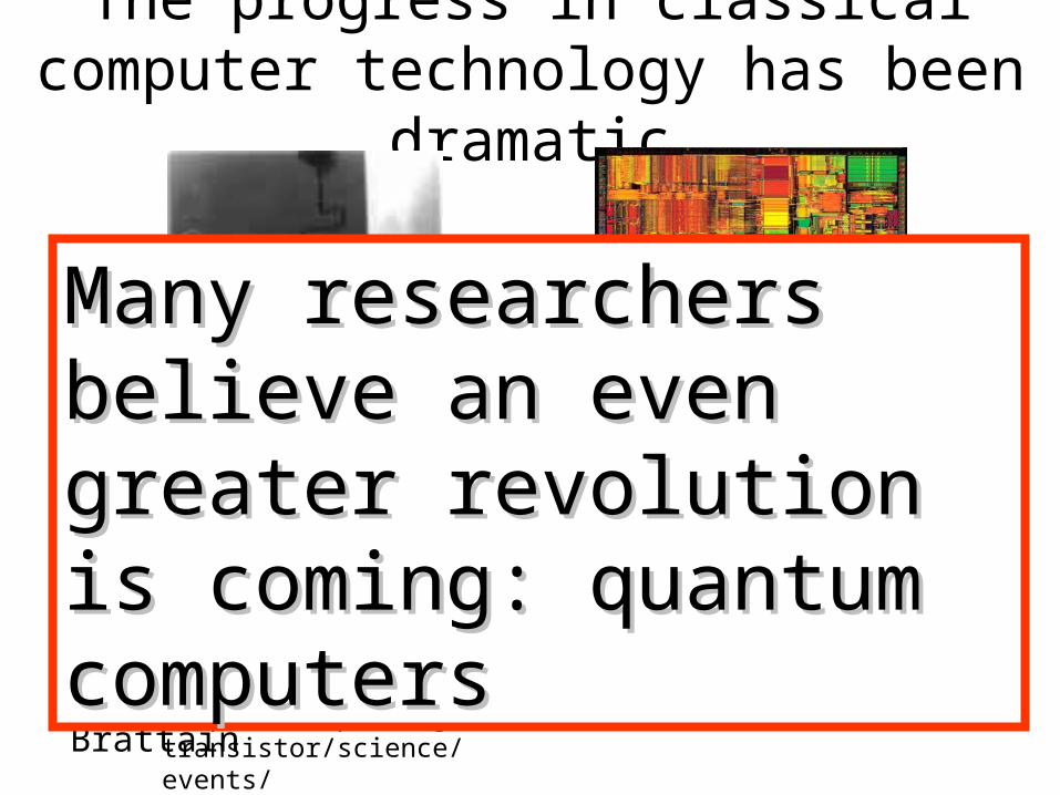
The progress in classical computer technology has been dramatic
1999 Pentium IIIBwww.icknowledge.com
http://www.pbs.org/transistor/science/events/pointctrans.html
1947 First point contact transistor
by Bardeen and Brattain
Many researchers believe Many researchers believe an even greater revolution an even greater revolution is coming: quantum is coming: quantum computers computers

Nano-systemHow small is a nanometer?
• 1 meter• 10 m• 1 m• 10 nm• 1nanometer• 0.1 nm• 1 picometer• 1 femtometer
– Size of red blood cell– = a millionth of a meter– Size of polio virus– = a billionth of a meter– Size of the hydrogen atom– = a trillionth of a meter– = 10 15 m, size of a proton

Number of Atoms in a Useful SystemFrom R. Keyes, IBM J. Res. Develop (1988)
# atoms to store a bit # dopant atoms/bipolar transistor

History• 1970s and 1980s, introduction of quantum
computers (Richard Feynmann, David Deutsch, and Paul Benioff)
• 1994, Peter Shor’s factoring algorithm• 1996, Lov Grover, searching algorithm• 1998, 1999, 2001 Isaac L. Chuang,
developed the world's first 2-qubit, 3-qubit, 5-qubit and 7-qubit quantum computer

People
Turing Machine …(1936)”
“… Quantum Circuits…(1985)”
First Ideas(1982)”
“…Factorization …(1997)”
A. TuringR. Feynmann
D. DeutschP. Shorr
Jiffy Quantum Theory
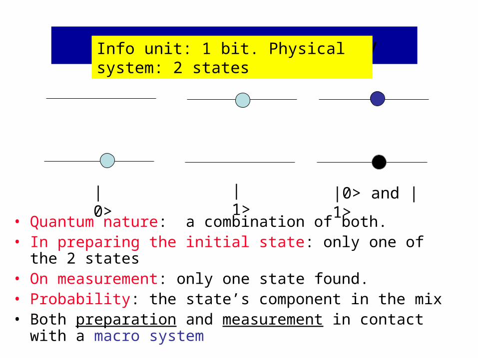
• Quantum nature: a combination of both.• In preparing the initial state: only one of the 2 states• On measurement: only one state found.• Probability: the state’s component in the mix• Both preparation and measurement in contact with a macro
system
|0>
|1>
|0> and |1>
Info unit: 1 bit. Physical system: 2 states

Qubit in a Ion Trap

Quantum Logic
Circuits
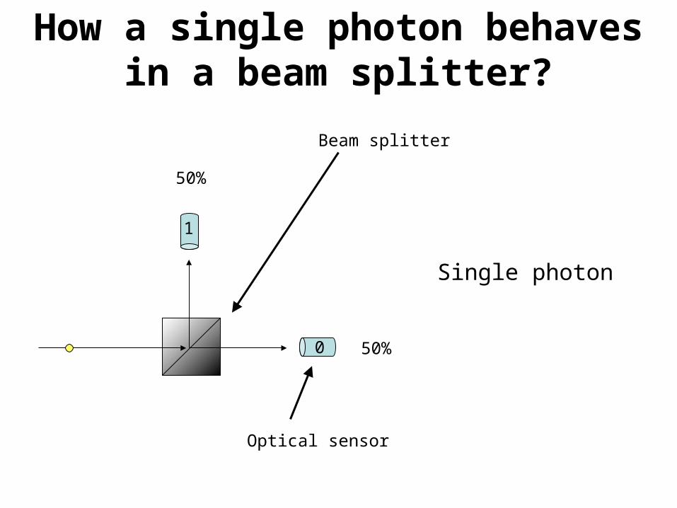
How a single photon behaves in a beam splitter?
50%
50%0
1
Beam splitter
Single photon
Optical sensor

… strange behavior
1
1
0
0
Mach-Zehnder apparatus

Quantum Gate: square root of NOT
0
1 0
1
NOT
1
1
0
0
notnot

Simple theory of the beam-splitter
0
1
0
1
%50
%50
The simplest explanation is that the beam-splitter acts as a classical coin-flip, randomly sending each photon one way or the other.

Quantum Interference
0
1
0
1 %100
The simplest explanation must be wrong, since it would predict a 50-50 distribution.

More experimental data collected to improve the theory
0
1
0
1
2cos2
2sin2

A new theory
0
1
0
1
2cos2
2sin2
12102
i 12
e02i i
The particle can exist in a linear combination or superposition of the two paths
12)1e(i02
1e ii

Probability Amplitude and Measurement
0
1
0
1
20
If the photon is measured when it is in the state then we get with probability and |1 with probability
10 10
21
20
0
121
20
21

Quantum Operations are linear
The operations are induced by the apparatus linearly, that is, if
andthen
12
i02112
102i10 1010
12102
i0
12i02
11
12i
2102
12i
1010

Quantum Operations are unitary
Any linear operation that takes statessatisfying
and maps them to statessatisfying
must be UNITARY
121
20 10 10
10 '1
'0 12'
12'
0

Linear Algebra notation for quantum circuits
10 10
0
01
1
10
1
010 1
001
corresponds tocorresponds tocorresponds to

2i
21
21
2i
corresponds to
corresponds to
ie0
01
Linear Algebra notation for quantum circuits

0
corresponds to
01
2i
21
21
2i
ie0
01
2i
21
21
2i
Linear Algebra notation for quantum circuits
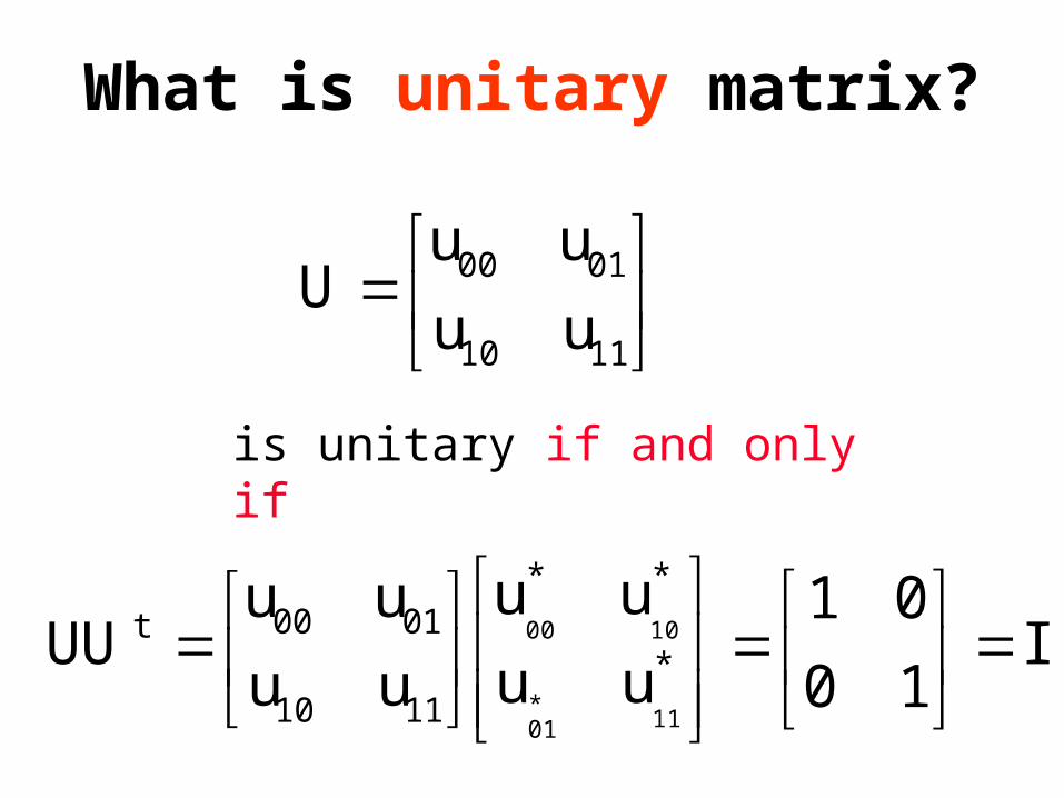
I1001
uuuu
uuuuUU *
**
1110
0100t
11*01
1000
1110
0100uuuuU
is unitary if and only if
What is unitary matrix?

Abstraction
The two position states of a photon in a Mach-Zehnder apparatus is just one example of a quantum bit or qubitExcept when addressing a particular physical implementation, we will simply talk about “basis” states and and unitary operations like
and
0 1
H

Qubits as binary Qudits• In multi-valued (MV) Quantum Computing (QC), the unit of memory
(information) is qudit.
• For instance, ternary logic values of 0, 1, and 2 are represented by a set of distinguishable different basis states of a qutrit.
• These states can be a photon’s polarizations or an elementary particle’s spins.
• After encoding these distinguishable quantities into multiple-valued values, qutrit states are represented by basis states |0>, |1> and |2> , respectively.
• A qubit, used in binary QC uses only two basis states, |0> and |1>
• Qubit and qutrit are then special cases of qudits A
B
AP
BQ
C CABR

H
21
21
21
21
Im
++--
Re
21
21
21
21
|0>
|1>
+-
21
21
Register-transfer notation for quantum circuits
|0> |0>
|1> |1>
10 10

ie0
01ie
|0>|1>
-
+
cos
sin
cos
sin
Register-transfer notation for quantum circuits
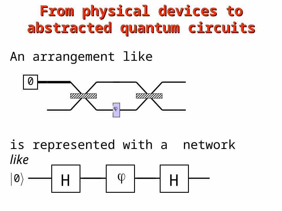
An arrangement like0
is represented with a network like
H H0
From physical devices to abstracted From physical devices to abstracted quantum circuitsquantum circuits

H 0 H
+
-
2
1
21
21
21
+
-
+
-
2
1
21
21
21
+
-
+
cos
-sin
cos
sin
Register-transfer notation for Register-transfer notation for quantum circuitsquantum circuits

• Superposition property may be mathematically described using the Kronecker product (tensor product) operation
• The Kronecker product of two matrices is defined as follows:
dvdzcvczdydxcycxbvbzavazbybxayax
vzyx
dvzyx
c
vzyx
bvzyx
a
vzyx
dcba
Kronecker Product of Matrices

(b)
H
(a)H
+
-
2
1
21
21
21
+
-
+
-
2
1
21
21
21
+
-
+
-
2
1
21
21
21
+
-
+
-
2
1
21
21
21
+
-
|0>
|0>
|1>
|1>
|00>
|01>
|10>
|11>
|0>
|1>
|00>
|01>
|10>
|11>
|0>
|1>
Register-transfer diagram Register-transfer diagram for two Hadamard gates in for two Hadamard gates in
parallelparallel

Quantum Parallelism
• Put all 7-bits into a superposition state• superposition allows quantum computer
to make calculations on all 128 possible numbers (27) in ONE iteration i.e. finishes in 1 second.
• Tremendous possibilities… imagine doing computations on even larger sample spaces all at the same time!!!

Kronecker Products for more Kronecker Products for more than one qubit circuitsthan one qubit circuits
10 10
If we concatenate two qubits
11100100 11011000
10 10
we have a 2-qubit system with 4 basis states0000 0110 1001 1111
and we can also describe the state as
or by the vector
1
0
1
0
11
01
0
00
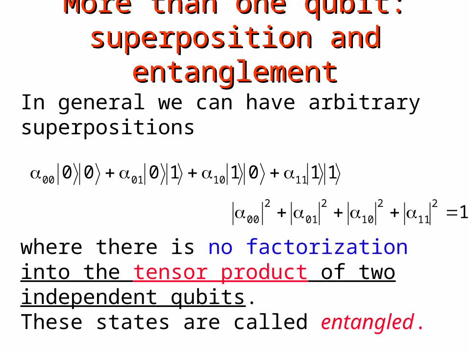
More than one qubit: superposition More than one qubit: superposition and entanglementand entanglement
In general we can have arbitrary superpositions
11011000 11100100
1211
210
201
200
where there is no factorization into the tensor product of two independent qubits.These states are called entangled.

Measuring multi-qubit systems
If we measure both bits of
we get with probability
11011000 11100100
yx 2xy

Classical Versus
Quantum
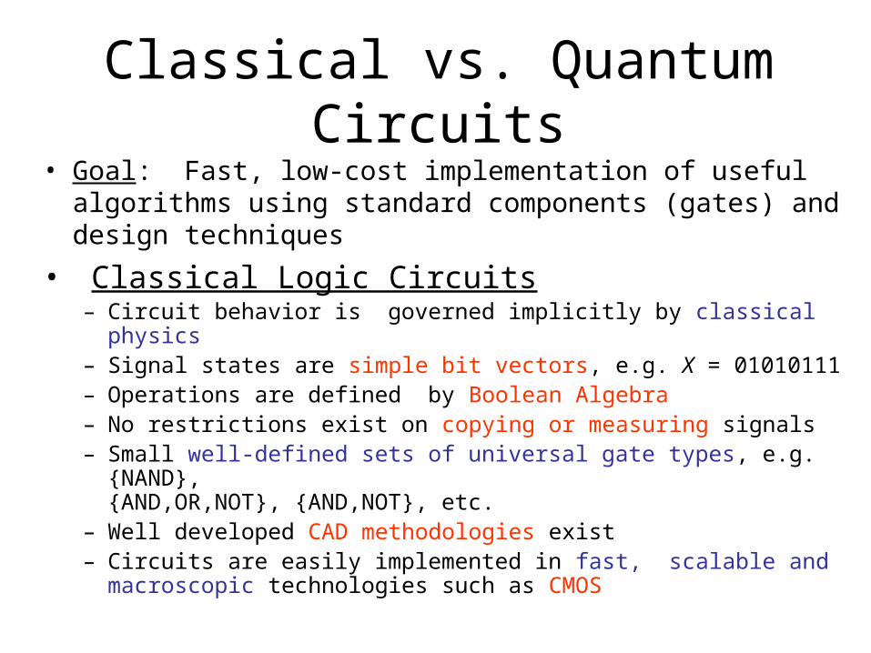
• Goal: Fast, low-cost implementation of useful algorithms using standard components (gates) and design techniques
• Classical Logic Circuits– Circuit behavior is governed implicitly by classical physics– Signal states are simple bit vectors, e.g. X = 01010111– Operations are defined by Boolean Algebra– No restrictions exist on copying or measuring signals– Small well-defined sets of universal gate types, e.g. {NAND},
{AND,OR,NOT}, {AND,NOT}, etc.– Well developed CAD methodologies exist– Circuits are easily implemented in fast, scalable and macroscopic
technologies such as CMOS
Classical vs. Quantum Circuits

• Quantum Measurement– Measurement yields only one state X of the superposed
states – Measurement also makes X the new state and so
interferes with computational processes– X is determined with some probability, implying
uncertainty in the result• States cannot be copied (“cloned”), implying that
signal fanout is not permitted• Environmental interference can cause a
measurement-like state collapse (decoherence)
Quantum Circuits are different

Decoherence

• Quantum Logic Circuits– Circuit behavior is governed explicitly by quantum mechanics– Signal states are vectors interpreted as a superposition of binary
“qubit” vectors with complex-number coefficients
– Operations are defined by linear algebra over Hilbert Space and can be represented by unitary matrices with complex elements
– Severe restrictions exist on copying and measuring signals– Many universal gate sets exist but the best types are not obvious– Circuits must use microscopic technologies that are slow, fragile,
and not yet scalable, e.g., NMR
Classical versus Quantum Circuits
ci in 1in 1i0i0
2n 1

• Unitary Operations– Gates and circuits must be reversible (information-
lossless)• Number of output signal lines = Number of input signal lines• The circuit function must be a bijection, implying that output
vectors are a permutation of the input vectors
– Classical logic behavior can be represented by permutation matrices
– Non-classical logic behavior can be represented including state sign (phase) and entanglement
More Quantum Circuit Characteristics

Classical vs. Quantum Circuits
Classical adder
cn–1
s0
s1
s2
s3
cn
a0
b0
a1
b1
a3
b3
a2
b2
Sum
Carry

Classical vs. Quantum CircuitsQuantum adder
Feynman gate

Reversible Circuits
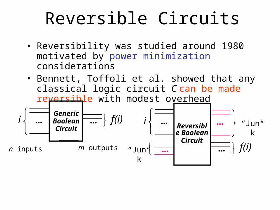
Reversible Circuits• Reversibility was studied around 1980 motivated by
power minimization considerations• Bennett, Toffoli et al. showed that any classical logic
circuit C can be made reversible with modest overhead
……
n inputs
GenericBooleanCircuit
m outputs
f(i)i …
Reversible BooleanCircuit
…
f(i)
…
…
“Junk”i
“Junk”

• How to make a given f reversible– Suppose f :i f(i) has n inputs m outputs– Introduce n extra outputs and m extra inputs– Replace f by frev: i, j i, f(i) j where is XOR
• Example 1: f(a,b) = AND(a,b)
• This is the well-known Toffoli gate, which realizes AND when c = 0, and NAND when c = 1.
Reversible Circuits
ReversibleANDgate
a
b
f = ab c
a
b
c
a b c a b f0 0 0 0 0 00 0 1 0 0 10 1 0 0 1 00 1 1 0 1 11 0 0 1 0 01 0 1 1 0 11 1 0 1 1 11 1 1 1 1 0

• Reversible gate family [Toffoli 1980]
Reversible Circuits
(Toffoli gate)• Every Boolean function has a reversible implementation using Toffoli gates.• There is no universal reversible gate with fewer than three inputs
Quantum Gates

• One-Input gate: NOTOne-Input gate: NOT– Input state: c0 + c1
– Output state: c1 + c0
– Pure states are mapped thus: and
– Gate operator (matrix) is
– As expected:
0 11 0
0 11 0
1 00 1
NOT
NOTNOT
0 11 0
0
10
1 01

One-Input gate: “Square root of NOT”
– Some matrix elements are imaginary– Gate operator (matrix):
– We find:
so with probability |i/2|2 = 1/2
and with probability |1/ 2|2 = 1/2
Similarly, this gate randomizes input – But concatenation of two gates eliminates the randomness!
i / 1/ 2 1/ 1/ 21/ 1/ 2 i / 1/ 2
12
i 11 i
12
i 11 i
10
12
i1
12
i 11 i
i 11 i
0 ii 0
NOTNOT

Quantum Gates
• One-Input gate: Hadamard
– Maps 1/ 2 + 1/ 2 and 1/ 2 – 1/ 2 . – Ignoring the normalization factor 1/ 2, we can write
xx (-1)xx xx – ––xx
• One-Input gate: Phase shift
12
1 11 1
H
1 00 e i

• Requirement:
• Hadamard and phase-shift gates form a universal gate set• Example: The following circuit generates
= cos 0 + ei sin 1 up to a global factor
Universal One-Input Quantum Gate Sets
U Any state
2H H 2

Quantum XOR gate• Called also Feynman gate or Controlled Not gate. • This gate allows inputs of |00> and |01> to appear
unchanged at the outputs, but interchanges the pairs |10> and |11>.
• For example, consider the quantum XOR gate’s operation for an input |10>.
1000
0100
0100100000100001
|00> |00>
|01> |01>
|10> |10>
|11> |11>

x
y
x
x y CNOT
1 0 0 00 1 0 00 0 0 10 0 1 0
– CNOT maps x xxand x xNOT x x xx looks like cloning, but it’s not.
– These mappings are valid only for the pure states and
x
y
x
x y
Quantum XOR gate

1 0 0 0 0 0 0 00 1 0 0 0 0 0 00 0 1 0 0 0 0 00 0 0 1 0 0 0 00 0 0 0 1 0 0 00 0 0 0 0 1 0 00 0 0 0 0 0 0 10 0 0 0 0 0 1 0
b
c
b
ab c
a a
|000>
|000>
|001> |001>
|110>
|010>
|111>
|011>
|010>
|011>
|100>
|101>
|100>|101>|110>|111>
3-Input gate: 3-Input gate: Controlled Controlled CNOT CNOT (C2NOT or (C2NOT or Toffoli gate)Toffoli gate)

• General controlled gates that control some 1-qubit unitary operation U are useful
Controlled Quantum GatesControlled Quantum Gates
U
u00 u01
u10 u11
C(U)
U
C2(U)
U
U
etc.

Universal Gate Sets• To implement any unitary operation on n qubits
exactly requires an infinite number of gate types• The (infinite) set of all 2-input gates is universal
– Any n-qubit unitary operation can be implemented using (n34n) gates [Reck et al. 1994]
• CNOT and the (infinite) set of all 1-qubit gates is universal
Quantum Gates

Discrete Universal Gate Sets• The error on implementing U by V is defined as
• If U can be implemented by K gates, we can simulate U with a total error less than with a gate overhead that is polynomial in log(K/)
• A discrete set of gate types G is universal, if we can approximate any U to within any > 0 using a sequence of gates from G
Quantum Gates
E(U,V )max
(U V )
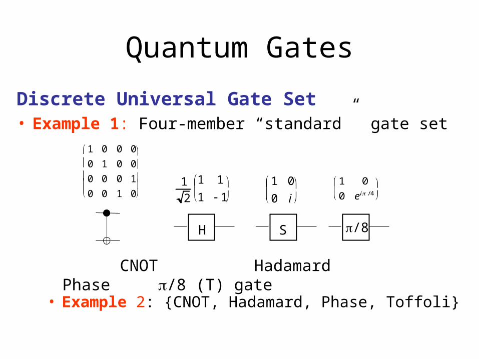
Discrete Universal Gate Set• Example 1: Four-member “standard” gate set
Quantum Gates
1 0 0 00 1 0 00 0 0 10 0 1 0
1
21 11 1
H
1 00 i
S /8
1 00 e i / 4
CNOT Hadamard Phase /8 (T) gate
• Example 2: {CNOT, Hadamard, Phase, Toffoli}

Quantum Circuits

• A quantum (combinational) circuit is a sequence of quantum gates, linked by “wires”
• The circuit has fixed “width” corresponding to the number of qubits being processed
• Logic design (classical and quantum) attempts to find circuit structures for needed operations that are– Functionally correct– Independent of physical technology– Low-cost, e.g., use the minimum number of qubits or gates
• Quantum logic design is not well developed!
Quantum Circuits

• Ad hoc designs known for many specific functions and gates• Example 1 illustrating a theorem by [Barenco et al. 1995]: Any
C2(U) gate can be built from CNOTs, C(V), and C(V†) gates, where V2 = U
Quantum Circuits
V V† V
=
U
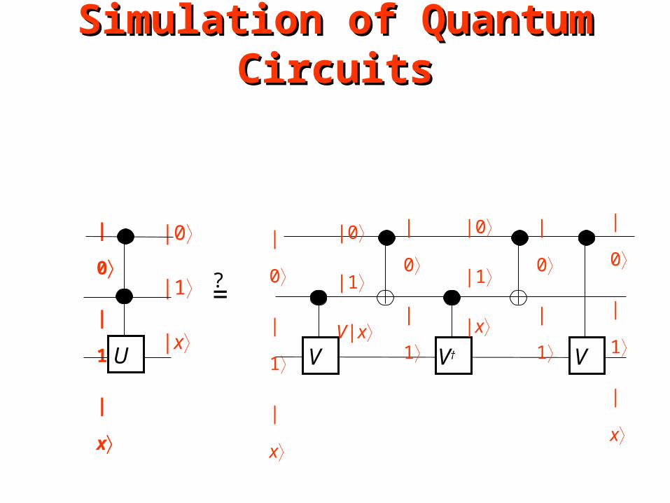
Simulation of Quantum CircuitsSimulation of Quantum Circuits
|0
|1
|x
|0
|1
|x
|0
|1
|xV V† V
=
U
|0
|1
V|x
|0
|1
|0
|1
|x
|0
|1
|0
|1
|x
?

|1
|1
|x
|1
|1
|x
|1
|1
U|x V V† V
=
U
|1
|1
V|x
|1
|0
|1
|0
V|x
|1
|1
|1
|1
U|x
Simulation continued
?
Simulation of Quantum CircuitsSimulation of Quantum Circuits

Algebraic Analysis of Quantum Circuits
U4U2 U3U1 U5U0
V V† V
=
U
?x1
x2
x3
• Is U0(x1, x2, x3) = U5U4U3U2U1(x1, x2, x3)
= (x1, x2, x1x2 U (x3) ) ?

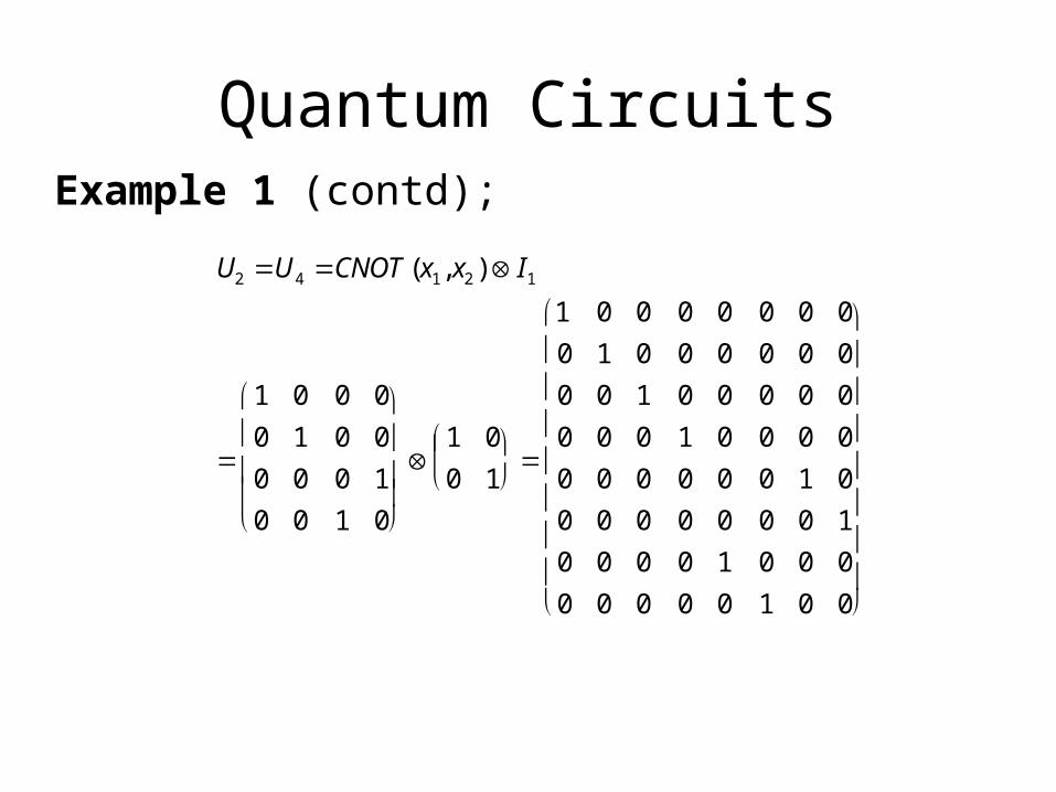
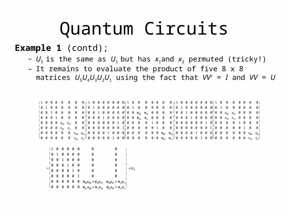
Quantum CircuitsExample 1 (contd);
U1 I1C(V)
1 00 1
1 0 0 00 1 0 00 0 v00 v01
0 0 v10 v11
1 0 0 0 0 0 0 00 1 0 0 0 0 0 00 0 v00 v01 0 0 0 00 0 v10 v11 0 0 0 00 0 0 0 1 0 0 00 0 0 0 0 1 0 00 0 0 0 0 0 v00 v01
0 0 0 0 0 0 v10 v11
Quantum CircuitsExample 1 (contd);
U2 U4 CNOT(x1, x2 ) I1
1 0 0 00 1 0 00 0 0 10 0 1 0
1 00 1
1 0 0 0 0 0 0 00 1 0 0 0 0 0 00 0 1 0 0 0 0 00 0 0 1 0 0 0 00 0 0 0 0 0 1 00 0 0 0 0 0 0 10 0 0 0 1 0 0 00 0 0 0 0 1 0 0
Quantum CircuitsExample 1 (contd);
– U5 is the same as U1 but has x1and x2 permuted (tricky!)– It remains to evaluate the product of five 8 x 8 matrices U5U4U3U2U1
using the fact that VV† = I and VV = U
1 0 0 0 0 0 0 00 1 0 0 0 0 0 00 0 1 0 0 0 0 00 0 0 1 0 0 0 00 0 0 0 v00 v01 0 00 0 0 0 v10 v11 0 00 0 0 0 0 0 v00 v01
0 0 0 0 0 0 v10 v11
1 0 0 0 0 0 0 00 1 0 0 0 0 0 00 0 1 0 0 0 0 00 0 0 1 0 0 0 00 0 0 0 0 0 1 00 0 0 0 0 0 0 10 0 0 0 1 0 0 00 0 0 0 0 1 0 0
1 0 0 0 0 0 0 00 1 0 0 0 0 0 00 0 v00 v10 0 0 0 00 0 v01 v11 0 0 0 00 0 0 0 1 0 0 00 0 0 0 0 1 0 00 0 0 0 0 0 v00 v10
0 0 0 0 0 0 v 01 v11
1 0 0 0 0 0 0 00 1 0 0 0 0 0 00 0 1 0 0 0 0 00 0 0 1 0 0 0 00 0 0 0 0 0 1 00 0 0 0 0 0 0 10 0 0 0 1 0 0 00 0 0 0 0 1 0 0
1 0 0 0 0 0 0 00 1 0 0 0 0 0 00 0 v00 v01 0 0 0 00 0 v10 v11 0 0 0 00 0 0 0 1 0 0 00 0 0 0 0 1 0 00 0 0 0 0 0 v00 v01
0 0 0 0 0 0 v10 v11
1 0 0 0 0 0 0 00 1 0 0 0 0 0 00 0 1 0 0 0 0 00 0 0 1 0 0 0 00 0 0 0 1 0 0 00 0 0 0 0 1 0 00 0 0 0 0 0 v00v00 v10v10 v00v01 v10v11
0 0 0 0 0 0 v01̀ v00 v11v10 v01v01 v11v11
U0

Quantum Circuits• Implementing a Half Adder
– Problem: Implement the classical functions sum = x1 x0 and carry = x1x0
• Generic design:
|x1
Uadd|x0|y1|y0
|x1|x0|y1 carry|y0 sum

Quantum Circuits
• Half Adder: Generic design (contd.)
UADD
1 0 0 0 0 0 0 0 0 0 0 0 0 0 0 00 1 0 0 0 0 0 0 0 0 0 0 0 0 0 00 0 1 0 0 0 0 0 0 0 0 0 0 0 0 00 0 0 1 0 0 0 0 0 0 0 0 0 0 0 00 0 0 0 0 1 0 0 0 0 0 0 0 0 0 00 0 0 0 1 0 0 0 0 0 0 0 0 0 0 00 0 0 0 0 0 0 1 0 0 0 0 0 0 0 00 0 0 0 0 0 1 0 0 0 0 0 0 0 0 00 0 0 0 0 0 0 0 0 1 0 0 0 0 0 00 0 0 0 0 0 0 0 1 0 0 0 0 0 0 00 0 0 0 0 0 0 0 0 0 0 1 0 0 0 00 0 0 0 0 0 0 0 0 0 1 0 0 0 0 00 0 0 0 0 0 0 0 0 0 0 0 0 0 1 00 0 0 0 0 0 0 0 0 0 0 0 0 0 0 10 0 0 0 0 0 0 0 0 0 0 1 0 0 0 00 0 0 0 0 0 0 0 0 0 0 0 1 0 0 0

Quantum Circuits
• Half Adder: Specific (reduced) design
|x1
|x0
|y
|x1
|y carry
sum C2NOT (Toffoli)
CNOT
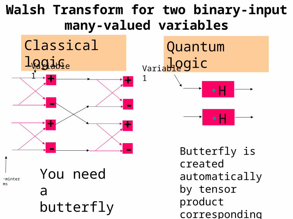
Walsh Transform for two binary-input many-valued variables
+
-+
-
+
-+
-
You need a butterfly
•H
Classical logic Quantum logic
•H
Butterfly is created automatically by tensor product corresponding to superposition
•minterms
Variable 1 Variable 1

Tremendous potential for
truly innovative research

Research Potential
• Our community should develop a systematic methodology and CAD tools for synthesizing, verifying, testing and simulating of quantum computers.
• These methods and tools will be counterparts of what exists now in binary CMOS.– Re-use spectral approaches, DDs, XOR logic, etc.
• Development of these tools will require understanding of real quantum circuit technology.

New Frontiers
Quantum Computer Quantum Mechanics
Quantum Logic
Quantum Computers
Quantum Programming

Open Problems in Quantum Circuits
• Synthesis of binary quantum cascades with no garbage or small garbage – (Maslov, Dueck, Miller, Kerntopf,
Perkowski, Khlopotine, Mishchenko, Curtis, Khan, Jha and Agrawal, Hayes, Markov)
• Synthesis of multiple-valued quantum cascades – (Muthukrishnan and Stroud, Miller
et al, Khan, Perkowski, Curtis, Lee, Denler)
– Universal gates, what are the counterparts of Toffoli and Fredkin gates?
Fredkin
Toffoli

Open Problems in Quantum Circuits
• What is the Fault Model for quantum circuits?– Technology dependent?
• Formal Verification of quantum circuits
• Test Generation for quantum circuits
• Fault Localization of quantum circuits
• Synthesis of testable quantum circuits
• Synthesis of fault-tolerant, error correcting quantum circuits.

Open Problems in Quantum Circuits
• What are universal gates?
• How to calculate costs of elementary gates for each quantum technology such as NMR or ion trap?
• What are the gates that can be truly realized in a quantum technology?
• What are the synthesis, analysis and test methods for sequential quantum circuits?

Open Problems in Quantum Circuits
• Invent new quantum algorithms.
• What are the principles to create quantum algorithms
• The nature of entanglement.
• Quantum computer architectures.
• Quantum formalisms. (Clifford algebras).
• Quantum Logic.
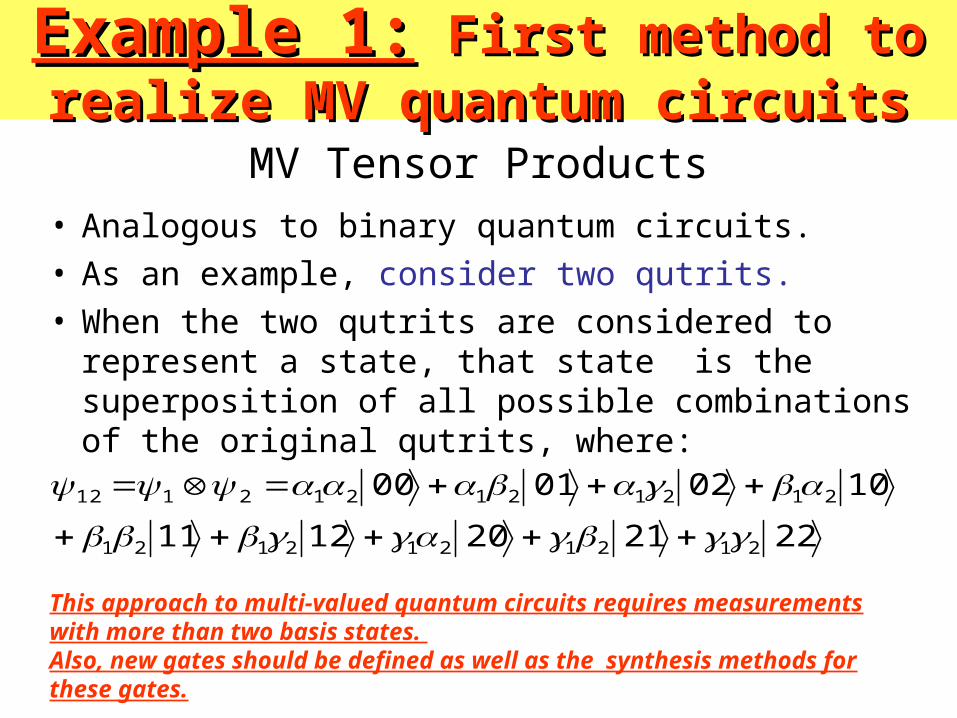
Example 1:Example 1: First method to realize First method to realize MV quantum circuitsMV quantum circuits
• Analogous to binary quantum circuits. • As an example, consider two qutrits. • When the two qutrits are considered to represent a
state, that state is the superposition of all possible combinations of the original qutrits, where:
2221201211
10020100
2121212121
212121212112
MV Tensor Products
This approach to multi-valued quantum circuits requires measurements with more than two basis states. Also, new gates should be defined as well as the synthesis methods for these gates.

Quantum MV Superposition• The superposition property allows the qubit states to grow
much faster in dimension than classical bits, and the qudits faster than qubits.
• In a classical system, n bits represent distinct states, whereas n qubits correspond to a superposition of 2n states and n qutrits correspond to a superposition of 3n states.
• Because in contemporary quantum technologies every qubit is costly, higher radices than 2 give an advantage of improved processing and storage power at the same realization cost.
• This is a strong argument for realization of multi-valued logic in quantum circuits.
• In addition to standard advantages of mv logic, quantum mv logic may be superior to binary one because of different nature of entanglement.

1
j
Bloch Sphere
• The normalization ||2 + ||2 = 1 admits the parametrization = cos(/2) e j , = sin(/2) e j.
• | = e j (cos ( / 2) |0 + e j sin ( / 2) |1 ).
• Since the global phase of | has no observable effect, we may write | = cos(/2) |0 + e j sin(/2) |1.
• The angles and define a point on the surface of a unit sphere – the Bloch sphere, see Fig. 1.
• The Bloch sphere provides an excellent tool to visualize the state vector of a qubit.
• This is a binary Bloch sphere, but a multi-valued counterpart of it can be also created.
Example 2:Example 2: Second Method to Second Method to realize MV quantum circuits.realize MV quantum circuits.

Second method to realize multi-valued logic using binary quantum computing (cont).
• Figure shows the location of 6 points, that may correspond to values of some multi-valued algebras.
• For binary logic we use |0 and |1.
• For quaternary logic we use |0, |1, |0+|1, and |0-|1.
• For 6-valued logic we may use additionally |0 + j |1 and |0 - j|1.
• A rotation or a combination of rotations leads from one value to any other value.
1
j

Second Method to realize MV quantum circuits (cont).
• Above we showed how multiple-valued logic can be encoded in binary quantum computing.
• Quaternary logic requires two binary measurements (readings).
• The first reading distinguishes states |0 and |1, and the second reading uses additional rotation gates to distinguish between states |0+|1, and |0-|1.
• It can be shown that the logic with 2n values requires n readings.

Example 3:Example 3: Quantum Circuit Quantum Circuit SimulationSimulation
• Simulation of quantum circuits plays absolutely fundamental role in many areas of quantum physics and engineering.
• Simulation is used to:– verify correctness of the design, – analyze its properties and – find some interesting aspects that cannot be found by “hand and
pencil” methods. – Fault simulation– Evolutionary algorithms
• Researchers routinely use quantum simulators to help them with inventions and verify their design guesses.

Fast simulation is extremely important
• Matrix methods are slow. • Acceleration is attempted to be achieved
by two fundamental methods: – (1) acceleration of standard operations by
using special hardware emulators, parallel computers or processor networks,
– (2) creating new advanced data structures to represent quantum data more efficiently using standard computers.

Example 4:Example 4: Quantum Decision Quantum Decision DiagramsDiagrams
• New data structures, such as QUIDDs [Viamontes, Markov, Hayes] allow for implicit parallelism when executing Kronecker multiplications on them.
• QUIDDs are based on ADDs and MTBDDs, • so hopefully in future other decision diagrams may be used
to represent quantum circuits. • It is also expected that basic software engines used
successfully in classical CAD (such as for instance SAT or ATPG methods) may be used to deal with quantum circuits.
• Also, the fast simulators based on new types of decision diagrams should be in future parallelized and possibly accelerated in FPGA-based boards.
• Even before quantum computers will be available, their emulations on standard computers and ASIC/FPGA may prove useful to solve some practical problems.

Example 5Example 5:: Testing and Testing and diagnosis of quantum circuitsdiagnosis of quantum circuits
• Patel, Markov, and Hayes showed that reversible circuits are much better testable than irreversible circuits.
– This is because every test covers half faults and every fault is covered by half tests.
– The reversible circuits are then “transparent” to faults, making them well observable and controllable.
• We showed that fault localization in reversible circuits is easier.
• We presented preliminary results on testing binary quantum circuits and on fault localization of quantum circuits.
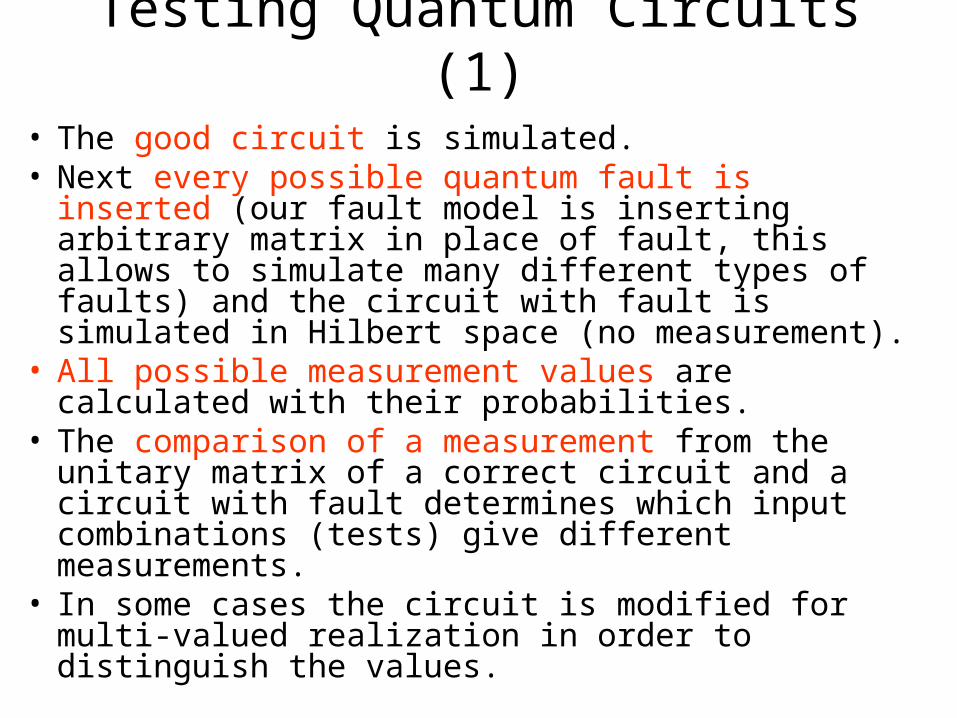
Testing Quantum Circuits (1)
• The good circuit is simulated. • Next every possible quantum fault is inserted (our
fault model is inserting arbitrary matrix in place of fault, this allows to simulate many different types of faults) and the circuit with fault is simulated in Hilbert space (no measurement).
• All possible measurement values are calculated with their probabilities.
• The comparison of a measurement from the unitary matrix of a correct circuit and a circuit with fault determines which input combinations (tests) give different measurements.
• In some cases the circuit is modified for multi-valued realization in order to distinguish the values.

Testing Quantum Circuits (2)• Observe that in contrast to standard testing
and reversible circuits testing, there are three types of faults in quantum domain: – (1) faults that can be detected deterministically, – (2) faults that cannot be detected (like global
phase faults), and – (3) faults that can be detected by repeated
application of tests, possibly with special measuring gates.
• These faults can be detected only with certain probability.
• Thus, quantum testing is probabilistic testing.

Research Challenges in Quantum Test
• Open problems include basically everything: – fault models, – fault simulation, – test generation, – test minimization, – fault coverage,– fault localization using probabilistic adaptive
trees.

Quantum Computational Intelligence (QCI)• The two most famous quantum
algorithms to date were created by Peter Shor and Lov Grover.
• Shor’s algorithm is for factoring integers:– It produces an exponential
computational speedup over classical algorithms
– It can break the RSA encryption techniques.
• Grover’s algorithm searches an unordered list of data, to find a particular item. – It has a provable quadratic speedup
over the best classical algorithm. – It is like looking for name of a person
in yellow pages knowing only his telephone number.

Research Challenges in Quantum Algorithms for Computational Intelligence• “How these algorithms can be used in the
field of Computational Intelligence?”. • Quantum computing is in every particular
instance at least as powerful as standard computing.
• It is therefore very reasonable to look for quantum counterparts to all concepts created in past in:– algorithm design, – Artificial Intelligence, – Machine Learning, – Computational Intelligence,– Soft Computing.

Future Applications in Structured Search• Grover algorithm for searching an unstructured database started many
practical applications because of the generality of its main idea – phase amplification.
• Grover himself extended his algorithm for the structured search problem, one of the main tough research issues in AI, with a multitude of important and practical applications, including in EDA.
• Many interesting papers about quantum search using problem structure were written by Hogg and collaborators.
• Boyer developed bound for quantum searching algorithms. • The class of NP-complete problems includes:
– graph coloring, – satisfiability, – planning, – set covering, – combinatorial optimization, – tautology verification – and many other problems
that are useful for instance to solve the synthesis and optimization problems.

Generalizations of gates, circuits and automata
• Because gates, the basic concept of quantum computing, are a powerful generalization of gates in standard computing, researchers are systematically generalizing all the fundamental concepts of computing to involve quantum concepts in one way or another.
• And thus; – a quantum circuit is a generalization of a combinational
Boolean circuit, – Quantum Automata (various formalizations) generalize
Finite State Machines, – Quantum Turing machine generalizes Turing Machines and
Probabilistic Turing Machines, – and so on.

From CI to QCI• The same tendency is seen in Computational Intelligence. • Its concepts and algorithms are being generalized to those of
the Quantum Computational Intelligence (QCI). • And thus;
– Quantum Neural Networks, – Quantum Associative Memories, – Quantum Bayesian Nets, – Quantum Games, – Quantum Markets, – Quantum Agents, – Quantum Formulas, – Quantum Fuzzy Networks, – Quantum Spectral Transforms and Networks, – Quantum Evolutionary Algorithms, – Quantum Braitenberg Vehicles,– and many others have been created and are actively investigated both theoretically, using
software simulators, hardware emulators and in real quantum circuits.

理论计算机科学中的几个问题应明生
清华大学计算机科学与技术系智能技术与系统国家重点实验室
Importance of intelligent learning

Research Challenges in NP problems
• Because laws of quantum mechanics proved useful to improve algorithmic performance of some NP problems, there is a high probability that more problems will find efficient solutions in quantum domain.

Quantum-Neural Algorithms:
• Quantum Associative Memories of Ventura and Martinez, • Competitive Learning in Quantum System by Ventura and
Perus. • While neural net processes real values, quantum NN
processes complex values. • It includes therefore standard NN and binary computers as
special cases• Thanks to superposition and entanglement can do much
more. • Weights that are complex values will allow to express much
more and higher order information. • Totally new algorithms can be invented for learning and using
such nets. • QuAM is analogous to a linear associative memory but all
neurons are quantum mechanical gates.

Research Challenges in QCI
• There are dual influences of CI and quantum computing. – 1. The quantum ideas can be used to create
powerful quantum-inspired algorithms to solve many types of problems in EDA, QDA and robotics.
– 2. The ideas and algorithms from many classical computer science areas can be now used in quantum domain or transformed and extended to quantum domain.
• Very little operational software packages that use these ideas.

Quantum Computational Intelligence
• Quantum Neural Nets
• Quantum Associative Memories
• Quantum Inspired Genetic Algorithms
• Learning by synthesis of quantum circuits
• Other models of learning based on quantum concepts.
• Quantum Braitenberg Vehicles.

In 2020 quantum computing will be In 2020 quantum computing will be a realitya reality
• As a community, we have a unique chance to work on the forefront of the future dominating technology.
• Logic design community did not have this opportunity in the past.
Quantum Circuit Design
And TechnologyMathematics
and logicQuantum Design
AutomationQuantum Information and
Quantum Computational Intelligence

Conclusions (1) • Emerging new area of Quantum Design Automation
(QDA). • Similarly as in design automation, there will appear
sub-areas of:– high level quantum synthesis, – logic level quantum synthesis, – quantum test, – quantum verification, – quantum simulation, – quantum software-hardware co-design, – quantum physical design, – automatic learning from examples, – data mining, – and so on.

Conclusions (2) • At the moment, even a single paper has been not
published in many of these areas• But surely they will appear in the forthcoming 10
years.
• We outlined some subjective choice of recent papers as a potential base of future research in QDA.
• Conventional logic synthesis, test and machine learning methods, for both binary and multiple-valued logic, form a powerful base of new approaches in quantum engineering.

Conclusions (3) • Similarly the data structures like decision
diagrams or fundamental algorithms such as satisfiability or reachability analysis continue to have their role.
• Because of high numerical demands of quantum logic there exist even higher expectations on these methods.
• Growing mutual influence of QDA and QCI, leading in long term to their unification.

My husband has not taken his decision yet, he is not sure if he should work on quantum
computing
Additional slides for questions

Multi-valued Quantum Circuit Synthesis
• Let us first briefly summarize current results in binary quantum circuit synthesis.
• This is the most advanced research area and there are two gate models for synthesis (especially for permutative circuits):– (1) The first gate model assumes that only gates with limited
number of inputs can be used (for instance universal Toffoli3 gate that operates on three qubits; P=a, Q=B, R=abc).
– We will call it the limited qubit gate model. – Observe that while in binary reversible logic all 2-bit gates are
linear and thus cannot be universal, in quantum logic there are very many universal 2-qubit gates (theoretically infinite).
– They can be all used in the limited qubit gate model, but there are no constructive methods yet to make use of this fact even for binary case.

Multi-valued Quantum Circuit Synthesis
• (2) The second gate model assumes that for any given number of qubits N for which a function is realized, there exist a Toffoli gate ToffoliN (or a similar universal gate in which one data qubit is controlled by more than 2 control qubits) that operates on N qubits.
• We will call it the unlimited qubit gate model. • In the first model it was proved by Shende et al that every
N-qubit reversible function which is represented by an even number of cycles, is realizable without constant wires (ancilla bits) and every N-qubit function that is represented by an odd number of cycles is realizable with N+1 wires (one ancilla bit).

• (Observe that every permutation matrix specifies the permutation of input/output minterms, so it is a permutation and can be described as a set of cycles of minterm numbers.
• Ancilla bits are also called constant inputs, dummy variables or input garbages). • In general, synthesis using this model is more difficult, but the results are closer
to the minimum. • In the second model every function is realizable, regardless its cycles number. • But it is at the cost of expensive and not necessarily quantum realizable gates
(such gates may require many ancilla bits internally, so they tend to hide the high cost of realizations obtained by the methods [27,28,65].)
• Otherwise, there are methods to realize these complex gates with small ancilla, but for large N the realization of each complex gate necessitates an exhaustive number of limited-qubit realizable gates.
• The model (2) should be thus combined with post-processing methods based on local peephole optimization.
• So far, not much comparisons between these various synthesis models, especially for real quantum realizable gates, have been done.
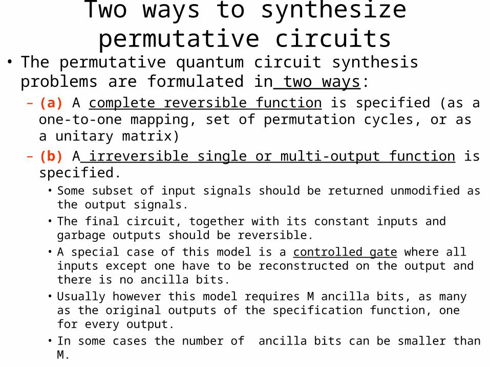
Two ways to synthesize permutative circuits• The permutative quantum circuit synthesis problems
are formulated in two ways:– (a) A complete reversible function is specified (as a one-to-
one mapping, set of permutation cycles, or as a unitary matrix)
– (b) A irreversible single or multi-output function is specified. • Some subset of input signals should be returned unmodified as the
output signals. • The final circuit, together with its constant inputs and garbage
outputs should be reversible. • A special case of this model is a controlled gate where all inputs
except one have to be reconstructed on the output and there is no ancilla bits.
• Usually however this model requires M ancilla bits, as many as the original outputs of the specification function, one for every output.
• In some cases the number of ancilla bits can be smaller than M.

• The first method is more elegant and does not create garbage.• It is restricted in that it assumes that a Boolean function has been
already converted to a reversible one (by appropriate adding of ancilla bits).
• For some formulations (like evolutionary programming and search) this method allows to be easily extended to non-permutative unitary matrices. – So far, however, only small circuits can be synthesized using this method,
even using very advanced algebraic and group-theoretic methods to decompose a larger matrix to a composition of smaller matrices.
• Because of its formulation, the second way is more similar to traditional logic synthesis.
• Methods developed previously for ESOPs, GFSOPs and similar forms in the AND/XOR logic synthesis are used for larger circuits, rather than methods specific to reversible design.

Research Challenges• This “adapted” approach allows now to realize larger
functions than the approach from (a), but when applied to multi-output functions usually leads to high garbage (one ancilla bit for each output).
• In the long run, perhaps this kind of methods will be better scalable since they use the structure of the function rather than relying on heuristic search methods, especially that there are no strong heuristics known so far.
• Finding structure in problems and finding good heuristics are the interrelated problems for future research, which will perhaps combine both ways (a) and (b).
• The problem of optimal conversion from irreversible to reversible function has been not solved yet.

Four Synthesis Models
• There exist the following synthesis models, both for binary and multiple-valued logic:
1. limited qubit gate model and full reversible function (way a). Usually zero or one ancilla bits are expected.
2. unlimited qubit gates and full reversible function (way a). Usually zero or one ancilla bits are expected.
3. limited qubit gates and single output function (way b). Usually at most M ancilla bits are expected.
4. unlimited qubit gates and irreversible input function (way b). Usually at most M ancilla bits are expected.

• Comparing to binary quantum circuit synthesis, multiple-valued quantum circuit synthesis is a relatively immature area of research.
• One can expect that it will repeat the history of development of algorithms in binary reversible logic.
• In binary, model (1) has been developed in [84]. • As related to multiple-valued quantum circuits, the model (1) of reversible
quantum circuits synthesis above has been investigated by [20] and by a Genetic Algorithm approach from [54].
• Model (2), investigated for binary case in [27,28,63,65,66], has been not yet investigated for multiple-valued logic (although [78] explains how it can be done).
• Model (3) is researched in paper [55] and some other preliminary results appear also in [78].
• Model (4) has been investigated in [4,50-55,59,60]. • It is important to distinguish among these four models, to avoid unrealistic
claims of superiority of one method over another, since obtaining solutions in some of these models is much easier than in the other ones.
Research Challenges
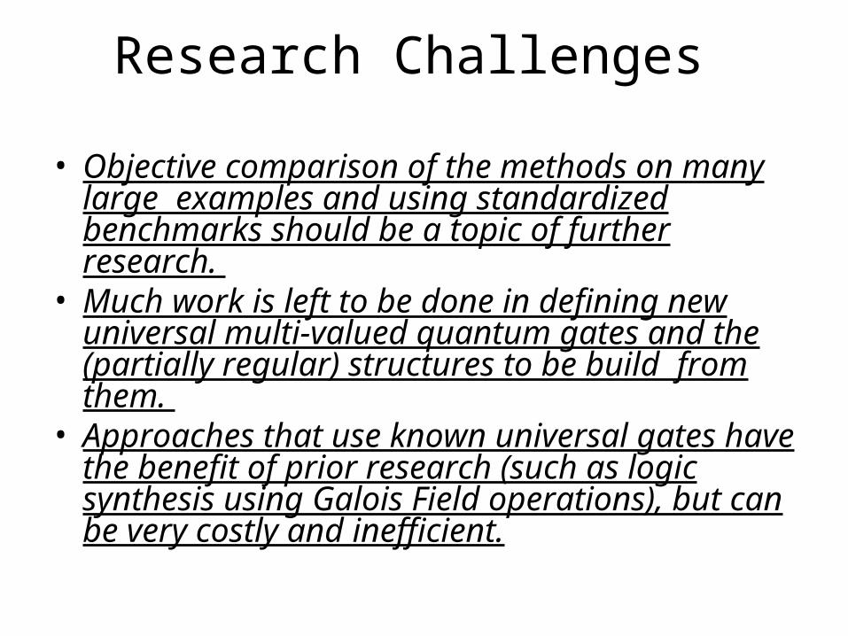
• Objective comparison of the methods on many large examples and using standardized benchmarks should be a topic of further research.
• Much work is left to be done in defining new universal multi-valued quantum gates and the (partially regular) structures to be build from them.
• Approaches that use known universal gates have the benefit of prior research (such as logic synthesis using Galois Field operations), but can be very costly and inefficient.

• Below we give a complete characteristics of papers in multi-valued quantum logic synthesis. Khan and Perkowski adapted the GFSOP (Galois Field Sum of Products) method to permutative (ternary) quantum circuits [52,53].
• The algorithm is based on finding a ternary decision diagram, and flattening it to quantum cascade-realizable GFSOP.
• In another work [54] these authors use Genetic Algorithm to synthesize multi-output, no-garbage cascades of arbitrary ternary quantum gates.
• The approach presented by Miller et al [65] is an extension of their greedy algorithm for binary circuits [27,28,63]. A non-published extension to their work presents also a method to encode ternary logic using standard binary qubits [66]. Observe that while binary quantum logic uses 1800 rotation, and the quaternary logic from [49] uses 900 rotations, they use 1200 rotations for one vertical plane of Bloch Sphere in ternary logic. While both ternary and quaternary model use two measurements to distinguish encoded signals, the quaternary method is more efficient. A paper [49] based on SAT and reachability analysis uses quaternary quantum logic to synthesize exact minimum binary circuits from Feynman, Inverter, Controlled-V and Controlled-V+ gates. (V is called a “square-root-of-NOT” since its repeated application negates the input signal, V V = NOT). A simple adaptation of this method allows to realize also quaternary quantum circuits with arbitrary input and output signals [78].

Research Challenges• Recent works suggest that many uniform general
methods can be created to realize various multiple-valued logics that will use generalized rotations with respect to 3 orthogonal basis axes, rotations by angles 2/k, where k>1 is a natural number.
• In general, rotations with respect to any axis n can be used, but using some of Z, X, and Y simplifies gates.
• Every existing algorithm for binary quantum circuit design can be extended to its various multiple-valued quantum counterparts, but these generalizations are not trivial and algorithms that use these gates are numerically very challenging.
• These problems form then a good base for new research by people who understand search-based EDA algorithms and multiple-valued logic.

Figure 2. 3*3 Toffoli gate
• Figure 2 presents a standard binary reversible Toffoli gate.
• Its ternary counterpart has Galois Field 2 operations of multiplication and addition replaced with Galois Field(3) operations.
A
B
AP
BQ
C CABR

• Observe that the internal structure of this gate is complex when using quantum realizable gates (Figure 3). The Controlled-V gate works like this: when the control (top) signal is |0>, the data input is forwarded to output with no change. When the control signal is |1> the operation of the lower box (so-called V) is executed. In our case this is a square-root-of-NOT operation. Thus if two Controlled-V gates in series are controlled by the same signal A, if A=1 then their qubit data line is a negation. Two such gates in series serve then as a controlled-NOT or Feynman gate. Also, the operation of V and V+ annihilate ( V V+ = I ) . The reader can simulate “by hand” the circuit from Figure 3a to see that it truly realizes the Toffoli3 gate. Let us observe that the circuit from Figure 3a can be redrawn to one from Figure 3b. This circuit emphasizes that both CNOT, CV and C V+ are Controlled-Gates that leave data signal unchanged when the control is |0> and apply its internal transformation (the symbol of this transformation is in the input to multiplexer) when the control is |1>.
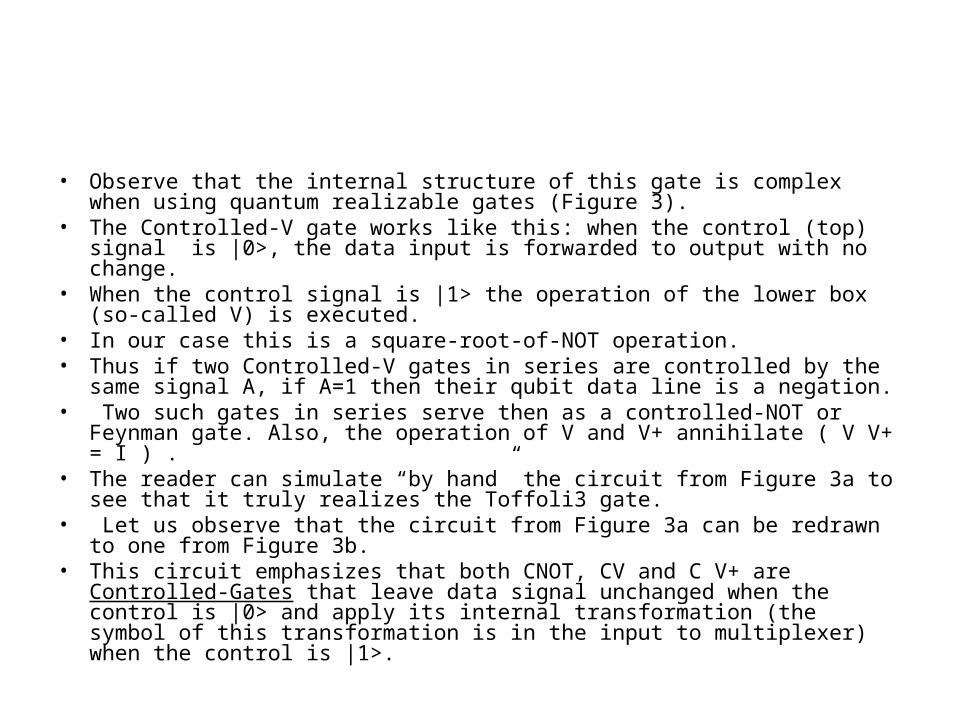
• Observe that the internal structure of this gate is complex when using quantum realizable gates (Figure 3).
• The Controlled-V gate works like this: when the control (top) signal is |0>, the data input is forwarded to output with no change.
• When the control signal is |1> the operation of the lower box (so-called V) is executed.
• In our case this is a square-root-of-NOT operation. • Thus if two Controlled-V gates in series are controlled by the same signal A,
if A=1 then their qubit data line is a negation.• Two such gates in series serve then as a controlled-NOT or Feynman gate.
Also, the operation of V and V+ annihilate ( V V+ = I ) . • The reader can simulate “by hand” the circuit from Figure 3a to see that it
truly realizes the Toffoli3 gate. • Let us observe that the circuit from Figure 3a can be redrawn to one from
Figure 3b. • This circuit emphasizes that both CNOT, CV and C V+ are Controlled-Gates
that leave data signal unchanged when the control is |0> and apply its internal transformation (the symbol of this transformation is in the input to multiplexer) when the control is |1>.

• Observe that any single-qubit operation can be written in the box, and also that any single qubit operation can be inserted to the control and data lines.
• The control can be from top (as in the Figure 3b) or from the bottom.
• The composition of this kind of multiplexed operations allows to create arbitrary permutative gate of reversible logic [55,59].
• Also, an arbitrary two-qubit quantum gate (described by a unitary matrix) can be constructed from such gates.
• These methods can be used to hierarchically synthesize larger circuits [55,59] and can be generalized to ternary (or in general multi-valued) logic (see Figure 4) for the realization of universal ternary permutative controlled gate.
• Universal quantum gate is created when operations are single-qubit ternary rotations.

Figure 3. Smolin/DiVincenzo realization of Toffoli gate as a prototype of a regular controlled quantum structure: (a) standard notation, (b) notation used in this paper to emphasize the similarity
A
B
C V V V+
P
R
S
A
B
C
P
R
S
(a)
(b)V V V+
+1 +1
•Observe that any single-qubit operation can be written in the box, and also that any single qubit operation can be inserted to the control and data lines.•The control can be from top (as in the Figure 3b) or from the bottom. •The composition of this kind of multiplexed operations allows to create arbitrary permutative gate of reversible logic [55,59]. •Also, an arbitrary two-qubit quantum gate (described by a unitary matrix) can be constructed from such gates.

Figure 4: Conceptual ternary multiplexer
op = Logical Operations:+0, +1, +2 represent Galois
Addition of constants 0, 1, and 2, respectively
01, 02, 12 represent logical replacement i.e. a 01 operation will replace 0->1, 1->0, and 2->2
•Also, an arbitrary two-qubit quantum gate (described by a unitary matrix) can be constructed from such gates. •These methods can be used to hierarchically synthesize larger circuits [55,59] and can be generalized to ternary (or in general multi-valued) logic (see Figure 4) for the realization of universal ternary permutative controlled gate. •Universal quantum gate is created when operations are single-qubit ternary rotations

Other problems in MV QC(1)New models of gates, such as above, that will be close to
realization and at the same time would allow creation of efficient synthesis algorithms, also for large circuits.
(2)Development of methods based on unitary matrix decomposition, group theory, Lie groups and Clifford algebras,
(3)Methods for incompletely specified functions, to be used in machine learning and data mining,
(4)Geometrical and topological visualization methods to help intuition of designers to design multi-qubit circuits (for instance generalizations of Bloch sphere, QUIDDs and Karnaugh Maps),
(5)Efficient methods for local optimization of quantum circuits on many levels of description,
(6)High-level quantum hardware description languages that will play in QDA a role similar to VHDL and Verilog in EDA,
(7)Development of formalisms and synthesis methods for sequential circuits.

• The name NP means non-deterministically polynomial, because there are no deterministic algorithms to solve NP problems in polynomial time (w.r.t the size of the problem).
• Any problem in the NP-complete class can be transformed into any other problem in this NP-complete class using polynomial number of steps.
• The quantum search algorithms can be used to solve the ”constraint satisfaction problems” into which all other NP-complete algorithms can be reduced [17].
• In a constraint satisfaction problems (SAT is the simplest example, graph coloring is another one) we deal with multi-valued variables and constraint rules on value relations between values of subsets of variables (relations like, “two adjacent nodes in a graph should have different colors”).
• In other words, one has to find assignment of values b to all a variables so that all constraints are satisfied.
• All such problems can be reduced theoretically to SAT, but this is not necessarily the best way to solve them.
• On a classical computer O(ba) assignments must be searched before finding a valid solution, if any.
• Using heuristics, or domain-dependent knowledge of a particular problem’s structure, the search can be dramatically speeded up to O(bka), where k1 and is problem dependent.
• Grover’s quantum search algorithm for structured problems further reduces the number of states searched to O(bak/2), which means a polynomial speedup over classical algorithms.
• This may be enough to solve many currently intractable problem instances [58].

Quantum Gate Arrays1-bit full adder
|0>
|0>
|x>
|y>
|c> |c>
|x>
|y>
|s>
|c’>
Let |c> = |1>, |x> = |0>, |y> = |1>
|0> |0> |1>
|1> |1> |0>
|s> = |0>, |c’> = |1>

Computation
0 0 00 0 10 1 00 1 11 0 01 0 11 1 0
1 1 1
G(x)
QC
G(0 0 0)G(0 0 1)G(0 1 0)G(0 1 1)G(1 0 0)G(1 0 1)G(1 1 0)
G(1 1 1)

Research Challenges on MV Research Challenges on MV quantumquantum
• There are very few papers on:– realization of multiple-valued quantum circuits, – design of practical MV quantum circuits,– algorithms using MV quantum circuits,– Quantum Computational Learning based on MV logic
• No known work on:– testing, – simulation and – algorithms for multiple-valued quantum circuit exist and
• Develop respective theories and QDA tools. • Develop Binary-encoded model of MV quantum
computing. • Develop truly multi-valued quantum model of multi-
valued computing.

• Because previous work on computational learning and particularly constructive induction designs arbitrary structures of arbitrary gates, it is applicable also to these structures and new algorithms can be created that generalize Ashenhurst Curtis decomposition.
• QuAMs are worse than classical algorithms on generalization, and our algorithms are very good in generalization.
• Therefore we believe that by extending model of QuAMs, a more general quantum structures will be found that will have good properties of QuAMs such as storing exponential number of patterns but will be also good in generalizing. It is well known that there exist animals with very few neurons, such as nematode worms.
• Still they can exhibit much more complex behaviors that a robot controlled by few neurons.
• The neuron used in NN theory is thus a big simplification of real neuron, and it is possible that quantum computing is used in brains of animals.
• In any case, the fact that actual neurons are more powerful than their current models is a powerful argument to investigate generalized models of neurons - especially quantum neurons.
Research Challenges in QCI

• Applicability of quantum paradigms in order to improve a Genetic Algorithm for solving the traveling salesman problem.
• The results of simulating quantum Genetic Crossover operators suggest that indeed quantum computation can speed up the search for solutions to the traveling salesman problem.
• Several successful experiments of various variants of Quantum-inspired GA have been described for several applications [40].
• In [30] quantum algorithms for searching trees are discussed, there are examples of trees for which the classical algorithm requires time exponential in n, but for which the quantum algorithm succeeds in polynomial time.
• Spectral Associative Memories (SAMs) are classical networks inspired by quantum mechanics and proposed by Spencer.
• They are quantized frequency domain formulations of conventional Contents Addressable Memories (CAMs).
• Non-local connectivity is made virtually by spectral convolution. • In classical CAMs attractors scale quadratically or polynomially.• In contrast, SAMs scale linearly with memory dimension. One model of the
neuron [61,62] is based on quantum holography [19]. • Phase is not only the essential parameter of physical significance, as in the
postulated model of quantum neural information processing, but the essential means by which holograms i.e. the 3 dimensional representations of objects may be encoded, decoded or transmitted.
Research Challenges in QCI

Quantum Notation• As shown, the resultant unitary matrix of an arbitrary quantum
circuit is created by matrix multiplications or Kronecker multiplications of matrices of its composing sub-circuits.
• Various quantum notations contribute to the difficulty in understanding the concepts of quantum computing.
• Generally, however, we believe that once the minimal amount of formalism is understood, logic researchers can quickly contribute to new designs.
• Much can be learned from the history of Electronic Design Automation as well as from MV logic theory and design.
• The lessons learned there should be used to design efficient QDA tools for MV quantum computing.
• Here we include the absolute minimum amount of formalism sufficient to start independent software development by people who have sufficient background in EDA tools and algorithms such as search or evolutionary programming