Framo 80 - Eberl Iron Works, Inc. · PDF file1Framo 80 Framo 80 03/2012 Framo 80 1-1 Beam...
26
Framo 80
Transcript of Framo 80 - Eberl Iron Works, Inc. · PDF file1Framo 80 Framo 80 03/2012 Framo 80 1-1 Beam...

Framo 80


Our service staff and application engineers will be pleased to offer you their assistance as to further information in detail, i. e. to answer your questions or to work out in co-operation with you specific solutions with the aid of our own planning soft-ware.
Unless otherwise stated, all load pa-rameters refer to mainly dead staticloads at ambient temperature. Theindicated permissible loads shouldbe regarded as nominal or workingloads and, unless otherwise denoted,refer to the main direction of the respective load; breaking loadvalues are not indicated.
This catalogue may be used by therecipient only. Each part of the catalogue constitutes the property ofSikla GmbH. All technical represen-tations as well as data are given tothe best of our knowledge. All repre-sentations and drawings are non-binding. We do not assume any liability whatsoever for typographicalmistakes or deficiencies.
Modifications and constructionalcorrections arising particularly fromtechnological development are excepted.
Notes
03/2
012
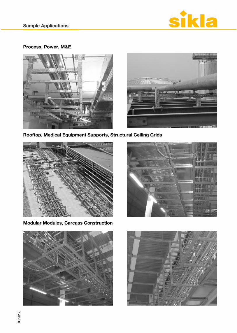
Process, Power, M&E
Rooftop, Medical Equipment Supports, Structural Ceiling Grids
Modular Modules, Carcass Construction
Sample Applications
03/2
012


1Framo 80
Framo 80
Framo 80 1-103/2
012
Beam Section TP F 80 Cantilever Bracket AK F 80 Beam Bracket TKO F 80
End Support STA F 80 End Support WBD F 80 Joining Plate AP
Welding Adapter ASA F 80GPL 100
Channel Adapter SA F 80 Self Forming Screw FLS F 80
Assembly Set P U-Holder SB F 80 Beam Section Holder TPH F 80
Page 1-3 Page 1-4 Page 1-5
Page 1-6 Page 1-7 Page 1-8
Page 1-9 Page 1-10 Page 1-11
Page 1-12 Page 1-13 Page 1-14

Framo 80
Framo 80 1-2 03/2
012
End Cap ADK F 80
Page 1-15

Beam Section TP F 80Group: A410
ApplicationMulti-function beam profile for horizontal, vertical and 3-D support structures in a wide variety of building and industrial applications.In addition to the high torsional resistance achieved using a totally closed profile, structural elements and pipe supports can be attached on all 4 sides with virtually no placement restrictions. Specifically designed mounting holes combined with special FLS Self Forming Screws ensure precise component placement and secure form-locked mountings.
Technical Data
For all values the effect of holes and perforations have been taken into account.
ApprovalsMPA approved
Framo 80
Framo 80 1-303/2
012
Type Weight [lb/ft]
Weight[kg/m]
Qty. [ft]
Qty.[m]
Partnumber
TP F 80 4.23 6.4 10 3 195031
Type Section modulus[in3 ]
Moment of inertia[in4 ]
Radius of inertia[in]
Torsional moment lt
[in 4 ]
Cross section A
[in2 ]
TP F 80 0.97 ly: 1.53lz: 1.53
iy: 1.16iz: 1.16
2.36 1.13
Type Section modulus[cm3 ]
Moment of inertia[cm4 ]
Radius of inertia[cm]
Torsional moment lt
[cm 4 ]
Cross section A
[cm2 ]
TP F 80 15.87 ly: 63.49lz: 63.49
iy: 2.95iz: 2.95
98.22 7.28
Material: Steel, hcp

Cantilever Bracket AK F 80Group: A420
ApplicationReady-to-use element for mounting to Beam Section F 80 and Beam Bracket TKO F 80 or for construction of cross bars with respective connecting element. Version "E" enables construction of a vertically hung Beam Bracket TKO F 80 with a Cantilever Bracket AK F 80 at the lowest point without any overlap of the mounting plate in the vertical plane.
ConfigurationWith pre-assembled End Cap ADK F 80
InstallationInterlocking connection to Beam Section F 80 by means of 4 Self Forming Screws FLS F 80.
Technical Data
ApprovalsMPA approved
Framo 80
Framo 80 1-4 03/2
012
Type W [lb]
W[kg]
Quantity[pack]
Partnumber
AK F 80-400 7.55 3.4 1 192764AK F 80-800 12.88 5.8 1 192771AK F 80-E-600 9.92 4.5 1 110370
Type L[in]
Dimensions of base plate[in]
Slots in base plate for[in]
AK F 80-400 15 3/4" 7 1/2" x 3 1/8" x 5/16" 3/8"AK F 80-800 31 1/2" 7 1/2" x 3 1/8" x 5/16" 3/8"AK F 80-E-600 23 5/8" 6 1/2" x 3 1/8" x 5/16" 3/8"
Type L[mm]
Dimensions of base plate[mm]
Slots in base plate for
AK F 80-400 400 190 x 80 x 8 M10AK F 80-800 800 190 x 80 x 8 M10AK F 80-E-600 600 165 x 80 x 8 M10
Configuration: Plate welded to Beam Section F 80Material:Plate Steel, hcpBeam Section Steel, hcp
AK F 80-E-600

Beam Bracket TKO F 80Group: A423
ApplicationReady-to-use element for mounting to walls, floors, ceilings and also can be mounted to Simotec Systems 100 and 120 or for assembling crossbars with the respective connecting element.
ConfigurationWith pre-assembled End Cap ADK F 80.
InstallationDepending on the situation, different options are recommended:
Technical Data
ApprovalsMPA approved
Framo 80
Framo 80 1-503/2
012
Type W [lb]
W[kg]
Quantity[pack]
Partnumber
TKO F 80-400 14.65 6.6 1 192788TKO F 80-800 20.42 9.2 1 192795
a) Fixing to building structure using 4 heavy duty anchors 1/2" (M12).b) Frictional connection to steel beams (flange width 3 1/8" - 4 3/4" / 80 -
120 mm) with Assembly Set P2.c) Interlocking connection to beams of System 100 or 120 by means of
Bracket Plates FV 100/120.
Type L[in]
Dimensions of base plate[in]
Slots in base plate for [in]
TKO F80-400 15 3/4" 8 5/8" x 8 5/8" x 1/2" 1/2"TKO F80-800 31 1/2" 8 5/8" x 8 5/8" x 1/2" 1/2"
Type L[mm]
Dimensions of base plate[mm]
Slots in base plate for
TKO F80-400 400 220 x 220 x 12 M12TKO F80-800 800 220 x 220 x 12 M12
Configuration Base plate welded to Beam Section F 80Material:Base plate Steel, hcpBeam Section Steel, hcp
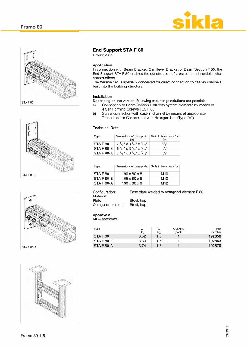
End Support STA F 80Group: A422
ApplicationIn connection with Beam Bracket, Cantilever Bracket or Beam Section F 80, the End Support STA F 80 enables the construction of crossbars and multiple other constructions.The Version "A" is specially conceived for direct connection to cast-in channels built into the building structure.
InstallationDepending on the version, following mountings solutions are possible:
Technical Data
ApprovalsMPA approved
Framo 80
Framo 80 1-6 03/2
012
Type W [lb]
W[kg]
Quantity[pack]
Partnumber
STA F 80 3.52 1.6 1 192856STA F 80-E 3.30 1.5 1 192863STA F 80-A 3.74 1.7 1 192870
a) Connection to Beam Section F 80 with system elements by means of 4 Self Forming Screws FLS F 80.
b) Screw connection with cast-in channel by means of appropriate T-head bolt or Channel nut with Hexagon bolt (Type "A").
Type Dimensions of base plate [in]
Slots in base plate for [in]
STA F 80 7 1/2" x 3 1/8" x 5/16" 3/8"STA F 80-E 6 1/2" x 3 1/8" x 5/16" 3/8"STA F 80-A 7 1/2" x 3 1/8" x 5/16" 1/2"
Type Dimensions of base plate [mm]
Slots in base plate for
STA F 80 190 x 80 x 8 M10STA F 80-E 165 x 80 x 8 M10STA F 80-A 190 x 80 x 8 M12
Configuration: Base plate welded to octagonal element F 80Material:Plate Steel, hcpOctagonal element Steel, hcp
STA F 80
STA F 80-E
STA F 80-A

End Support WBD F 80Group: A421
ApplicationEnd Support WBD F 80 is ideal for making supports for wall and floor mounting, as well as crossbars in conjunction with Beam Section F 80.Beside the direct connection to building structure, different base plates allow an immediate connection to various flange widths.For crossbar constructions, version WBD F 80-T has to be used. The octagonal connection allows max. use of section width without interfering screws or plates.
InstallationDepending on the situation, different options are recommended:
Technical Data
ApprovalsMPA approved
Framo 80
Framo 80 1-703/2
012
Type W [lb]
W[kg]
Quantity[pack]
Partnumber
WBD F 80-80/120 11.46 5.2 1 192801WBD F 80-121/160 19.18 8.7 1 192818WBD F 80-161/200 22.48 10.2 1 192825WBD F 80-201/300 20.72 9.4 1 192832WBD F 80-T 10.58 4.8 1 192849
a) Fixing to building structure using 4 heavy-duty 1/2" anchors resp. 5/8".b) Frictional connection to steel beams using Assembly Set P2, P3 or
respective Beam Clip.c) Form-locking connection to beam systems STF 100 or 120 using
Bracket Plates FV 100/120.
Type for flange width[in]
Dimensions of base plate[in]
Slots in base plate for[in]
WBD F 80-80/120 3 1/8" - 4 3/4" 8 5/8" x 8 5/8" x 1/2" 1/2"WBD F 80-121/160 4 3/4" - 6 1/4" 14 3/16" x 10 1/4" x 1/2" 1/2"WBD F 80-161/200 6 1/4" - 7 7/8" 14 3/16" x 12 1/4" x 1/2" 5/8"WBD F 80-201/300 7 7/8" - 11 3/4" 16 1/2" x 8 5/8" x 1/2" 5/8"WBD F 80-T 3 1/8" - 4 3/4" 8 5/8" x 8 5/8" x 1/2" 1/2"
Type for flange width[mm]
Dimensions of base plate[mm]
Slots in base plate for
WBD F 80-80/120 80 - 120 220 x 220 x 12 M12WBD F 80-121/160 121 - 160 320 x 260 x 12 M12WBD F 80-161/200 161 - 200 320 x 310 x 12 M16WBD F 80-201/300 201 - 300 420 x 220 x 12 M16WBD F 80-T 80 - 120 220 x 220 x 12 M12
Configuration: Base plate welded to square F 80 resp. octagonal element F 80
Material:Plate Steel, hcpSquare F 80 Steel, hcpOctagonal element F 80 Steel, hcp
WBD F 80-T

Joining Plate APGroup: A630
ApplicationPermits the connection of Beam Bracket TKO F 80 to flange widths > 4 3/4", as well as to building structures by means of heavy load anchors.
ConfigurationJoining Plate AP Assembly Set AP:4 Countersink Screws 1/2"4 Hexagon Nuts 1/2"4 Washers
Installation
Technical Data
Framo 80
Framo 80 1-8 03/2
012
Type W [lb]
W[kg]
Quantity[pack]
Partnumber
AP 121/160 17.42 7.9 1 183953AP 161/200 20.50 9.3 1 183962AP 201/300 18.74 8.5 1 183980
1) Interlocking connection of Joining Plate with Beam Bracket TKO F 80 by means of countersink screws and hexagon nuts.
2a) Fixing to concrete by means of 4 heavy-load anchors 1/2" or 5/8" (from Type AP 161/200 on).
2b) Frictional connection to steel beams by means of Assembly Set P2 or P3 (from Type AP 161/200 on).
Type for flange width[in]
Dimension of base plate[in]
Slots in base plate for[in]
AP 121/160 4 3/4" - 6 5/16" 12 3/5" x 10 1/4" x 1/2" 1/2"AP 161/200 6 5/16" - 7/8" 12 3/5" x 12 1/4" x 1/2" 5/8"AP 201/300 7 7/8" - 11 3/4" 16 1/2" x 8 11/16" x 1/2" 5/8"
Type Dimension of base plateL x B [mm]
Perforation for Connection to flange width[mm]
AP 121/160 320 x 260 x 12 M12 121 - 160AP 161/200 320 x 310 x 12 M16 161 - 200AP 201/300 420 x 220 x 12 M16 201 - 300
Material: Steel, hcp

Welding Adapter ASA F 80 GPL 100Group: A430
ApplicationElement to be used for flexible welding to beams, welding plates or further suitable weldable connection spots. In connection with Beam Bracket TKO, Cantilever Bracket AK or Beam Section F 80, the Welding Adapter allows the construction of crossbars, cantilevers, as well as further construction possiblities.
InstallationApply the base plate adapter side to the connecting element and weld on. The weldable hcp-surface requires an aftertreatment of corrosion protection only at and around the weld seam. The other native connection with Beam Section F 80 is done by means of 4 Self Forming Screws FLS F 80.
Technical Data
Framo 80
Framo 80 1-903/2
012
Type W [lb]
W[kg]
Quantity[pack]
Partnumber
ASA F 80 GPL 100 5.79 2.63 1 111741
Type Dimension of base plate[in]
Dimension of base plate[mm]
ASA F 80 GPL 100 3 15/16" x 3 15/16" x 13/16" 100 x 100 x 20
Configuration: Base plate welded to element F 80Adm. load:Cantilever: max. 1.0 kNmCrossbar: See Framo Installation Guidelines
Material: Steel, hcp, weldable

Channel Adapter SA F 80Group: A430
ApplicationAllows the compatibility of 1 - 5/8" framing system (channels 1 5/8" x 1 5/8" or 1 5/8" x 1 5/8" D) with Beam Section F 80. Simple construction of pipe lines or constructions, optionally with further parts of the Siconnect System. Thanks to the Pressix CC-Technology the channel can be connected directly to the Channel Adapter.
InstallationInterlocking connection to Beam Section F 80 by using 4 Self Forming Screws FLS F 80.
Technical Data
Framo 80
Framo 80 1-10 03/2
012
Type W [lb]
W[kg]
Quantity[pack]
Partnumber
SA F 80-41 3.10 1.4 1 192887
Type Dimension of base plate[in]
Slots in base plate[in]
SA F 80-41 7 1/2" x 3 1/8" x 5/16" 3/8"
Type Dimension of base plate[mm]
Slots in base plate
SA F 80-41 190 x 80 x 8 M10
Configuration: Base plate welded to U-PofileMaterial:Plate: Steel, hcpU-Profile: Steel, hcp

Self Forming Screw FLS F 80Group: A430
ApplicationThreaded Self Forming Screw for formlocking connection of Framo system components and Siconnect products to Beam Section F 80.The beam section material is locally cold-hardened due to the non-cutting forming. The high resulting edge-covering and a threaded connection between Self Forming Screw and Beam Section prevents from accidental unscrewing. During assembly process, the special interlocking prevents from overtightening.
Technical Data
ApprovalsMPA tested
Framo 80
Framo 80 1-1103/2
012
Type W [lb]
W[kg]
Quantity[pack]
Partnumber
FLS F 80 0.04 0.02 100 192512
Type Tightening torque[ft/lbs]
Tightening torque[Nm]
FLS F80 44.25 60
Material: Steel, hcp
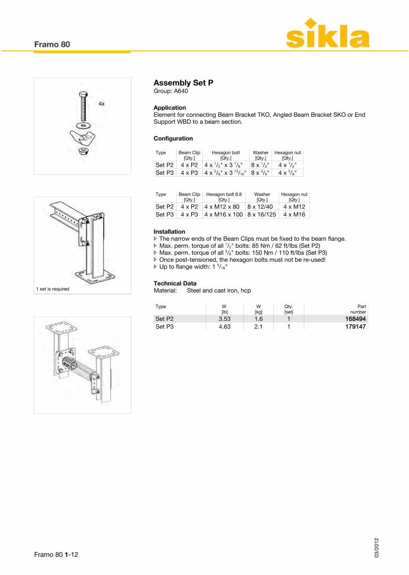
Assembly Set PGroup: A640
ApplicationElement for connecting Beam Bracket TKO, Angled Beam Bracket SKO or End Support WBD to a beam section.
Configuration
InstallationThe narrow ends of the Beam Clips must be fixed to the beam flange. Max. perm. torque of all 1/2" bolts: 85 Nm / 62 ft/Ibs (Set P2) Max. perm. torque of all 5/8" bolts: 150 Nm / 110 ft/Ibs (Set P3) Once post-tensioned, the hexagon bolts must not be re-used! Up to flange width: 1 5/16"
Technical Data
Framo 80
Framo 80 1-12 03/2
012
Type W [lb]
W[kg]
Qty.[set]
Partnumber
Set P2 3.53 1.6 1 168494Set P3 4.63 2.1 1 179147
Type Beam Clip[Qty.]
Hexagon bolt[Qty.]
Washer[Qty.]
Hexagon nut[Qty.]
Set P2 4 x P2 4 x 1/2" x 3 1/8" 8 x 1/2" 4 x 1/2"Set P3 4 x P3 4 x 5/8" x 3 15/16" 8 x 5/8" 4 x 5/8"
Material: Steel and cast iron, hcp
Type Beam Clip[Qty.]
Hexagon bolt 8.8[Qty.]
Washer[Qty.]
Hexagon nut[Qty.]
Set P2 4 x P2 4 x M12 x 80 8 x 12/40 4 x M12Set P3 4 x P3 4 x M16 x 100 8 x 16/125 4 x M16
1 set is required
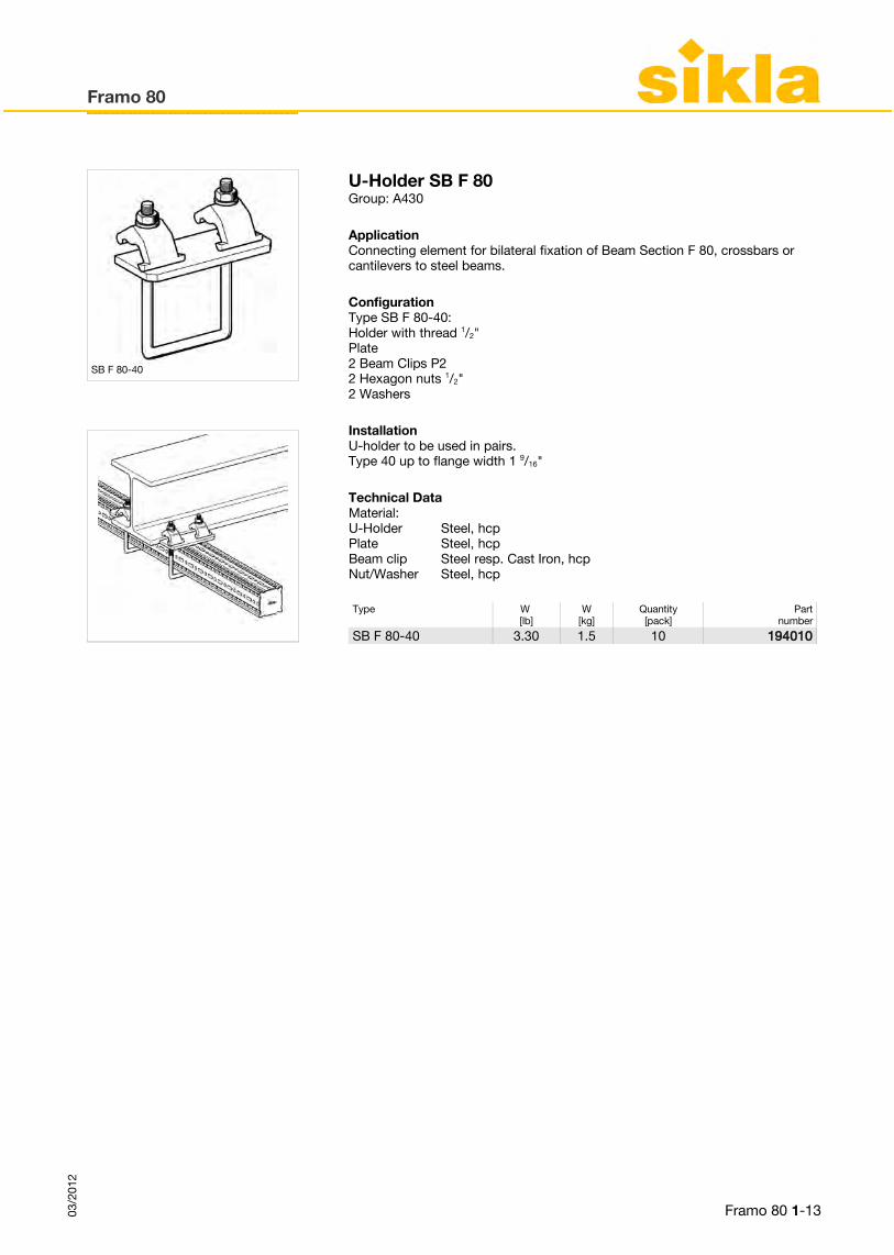
U-Holder SB F 80Group: A430
ApplicationConnecting element for bilateral fixation of Beam Section F 80, crossbars or cantilevers to steel beams.
ConfigurationType SB F 80-40:Holder with thread 1/2"Plate2 Beam Clips P22 Hexagon nuts 1/2"2 Washers
InstallationU-holder to be used in pairs.Type 40 up to flange width 1 9/16"
Technical Data
Framo 80
Framo 80 1-1303/2
012
Type W [lb]
W[kg]
Quantity[pack]
Partnumber
SB F 80-40 3.30 1.5 10 194010
Material:U-Holder Steel, hcpPlate Steel, hcpBeam clip Steel resp. Cast Iron, hcpNut/Washer Steel, hcp
SB F 80-40
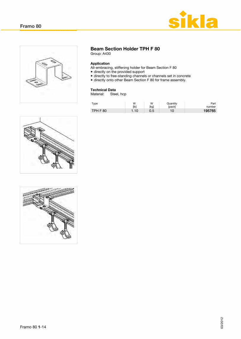
Beam Section Holder TPH F 80Group: A430
ApplicationAll-embracing, stiffening holder for Beam Section F 80
directly on the provided support directly to free-standing channels or channels set in concrete directly onto other Beam Section F 80 for frame assembly.
Technical Data
Framo 80
Framo 80 1-14 03/2
012
Type W [lb]
W[kg]
Quantity[pack]
Partnumber
TPH F 80 1.10 0.5 10 195765
Material: Steel, hcp

End Cap ADK F 80Group: A430
ApplicationEnd cap for a clean finish of closing the ends of Beam Section F 80, Cantilever Brackets, as well as Beam Brackets.
Technical Data
Framo 80
Framo 80 1-1503/2
012
Type W [lb]
W[kg]
Quantity[pack]
Partnumber
ADK F 80 0.06 0.03 25 192674
Material: PE, yellow

Framo 80
Framo 80 1-16 03/2
012
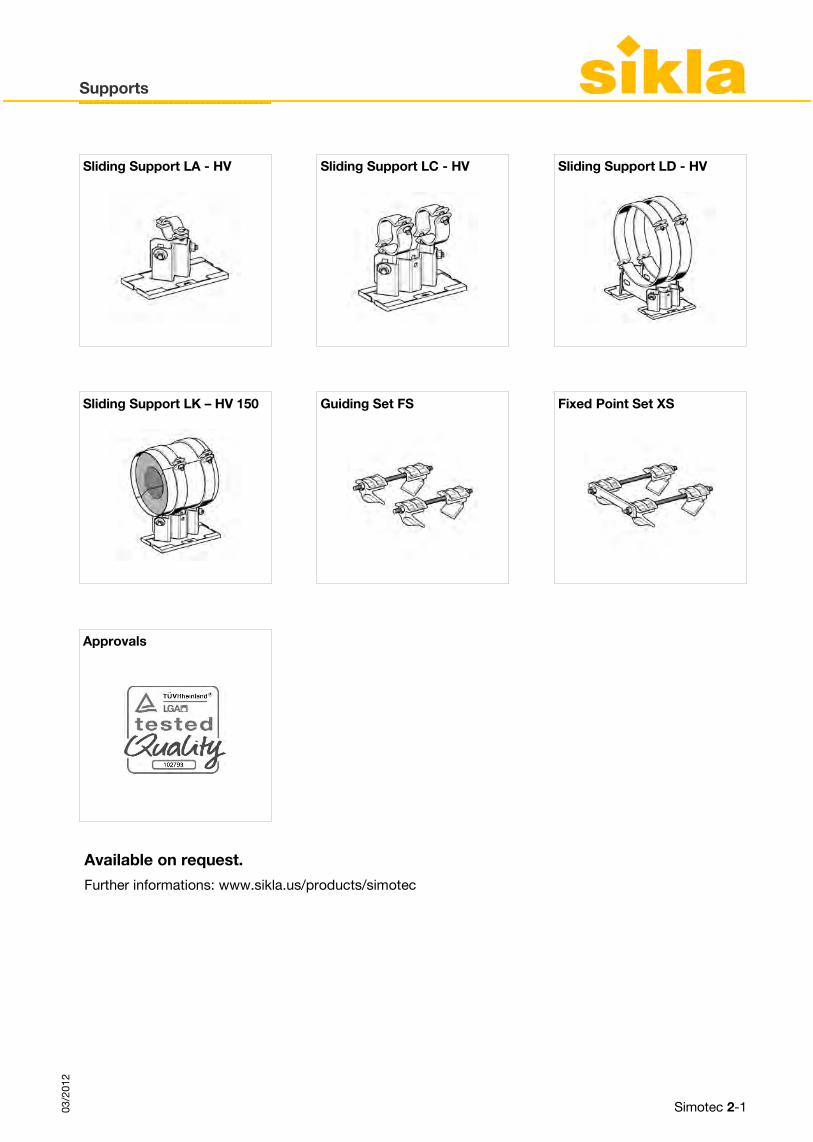
4Supports SSliding Support LA - HV Sliding Support LC - HV Sliding Support LD - HV
Sliding Support LK – HV 150 Guiding Set FS Fixed Point Set XS
Approvals
Available on request.
Further informations: www.sikla.us/products/simotec
Supports
Simotec 2-103/2
012


4Supports
Available on request.
Further informations: www.sikla.us/products/simotec
Speed Nut NT CC 41 - for all 1 5/8“ channel profiles, independent of the depth of the channnel
Very useful for retaining the channel nut in place when the application calls for the installation of vertical channels or in place, which are difficult to access. Further benefits:
♦ No spring to clash with the slots in the channel profile. ♦ No appearance of settlement after tightening.
Subassemblies
Simotec 3-103/2
012

![sikla KAT-F80 USA 13Framo 80 03/2012 Framo 80 1-5 Type W [lb] W [kg] Quantity [pack] Part number TKO F 80-400 14.65 6.6 1 192788 TKO F 80-800 20.42 9.2 1 192795 a) Fixing to building](https://static.fdocuments.in/doc/165x107/60e9f58a71629e6a2e0d5d74/sikla-kat-f80-usa-13-framo-80-032012-framo-80-1-5-type-w-lb-w-kg-quantity-pack.jpg)