Framo / Simotec Design Guidelines PDF
29
Simotec Installation Guidelines 2016
Transcript of Framo / Simotec Design Guidelines PDF
SimotecInstallation Guidelines 2016
Content
101/2
016
Notes 2
Framo 80 3
Framo 100 4 - 8
Framo 100/160 9 - 13
Framo 100/160 combi 14 - 15
Beam System 100 16 - 18
Beam System 120 19 - 21
Supports (Pipe Shoes) 22 - 24
Technical Information 25 - 28
Sikla GmbH Overseas & Export Dept.In der Lache 17D-78056 VS-Schwenningen
Telephone +49 7720 948 453Fax +49 7720 948 353
email [email protected]://www.sikla.com
Notes
2 01/2
016
Application
Sikla „Installation Guidelines“ is intended to provide guidance for supporting constructions within industrial pipework and plant engineering consisting of the Sikla Systems Framo 80, Framo 100, Beam System 100 and Beam System 120.All Sikla Systems mentioned above are certified according to EN 1090 and may therefore be used to EXC 2 for load- bearing structures.
Basis of calculation
Eurocode 3 (DIN EN 1993) „Design of steel structures“ provides the basis for determining the load capacity. Regarding serviceabi-lity the specified restrictions are allocated separately according to the design of the individual constructions. These limits may also be specified differently by the client. All deformations are determined on the basis of characteristic loads (γF = 1.0). The values of the permissible loads comply simultaneously the ultimate limit state and the serviceability limit state design. The respective gover-ning load is listed as Fz, perm in the Installation Guideline.
Load effects
Specified are permissible vertical loads Fz, perm in kN (e.g. pipeline weights), which have to be understood as maximum values of characteristic load effects and consider a safety factor γF = 1.35. Some Sikla constructions take into account additional friction forces Fx = Fz * μ0 for Sikla Pipe Shoes based on hot-dipped gal-vanized surface of Sikla beams which are calculated from pipe weight Fz and a friction coefficient μ0 = 0.2. These variable forces from pipe expansion are taken into account with a safety factor γF = 1.5. Sliding or guided Pipe Shoes (Sikla slide elements) with a higher coefficient μ0 > 0.2 (e.g. steel on steel) require an individual calculation.
Conditions
All loads are static loads at room temperature unless stated otherwise. Technical notes of the respective product data sheets for use and application range must be observed.
Load transmission into building structure
When fixing by anchors, or connection to existing cast-in channels, the structural safety analysis for the components used for this purpose must be done separately. When connecting to existing steel structures on site, resilience, support and torsional rigidity of the existing structure must be checked separately. In addition, when connecting with clamping sets, the static friction between clamping set and the on-site steel structure must fulfill the condition μ0 ≥ 0.2 (Sliding Surfaces Class D). On-site steel structure sizes (flange widths) of ≥ 100 mm are considered by using clamps for connection points. Unless shown otherwise: force direction Fx = steel structure longitudinal axis. Connections to concrete are designed with anchor type VMZ-A M12 (ETA-10/0260) in concrete strength C20/C25 under the design specifications hstd ≥ 2 hef edge distance c ≥ 120 mm. Axis distances are determined by the components. Reduction factor α A = 0.7 for structural steel flange sizes ≥ 201 mm for End Support WBD F100 + F100/160.
Technical InformationInstallation conditions are summarized at the end of this brochure - in particular specifications regarding tightening torques, bolt spacing, general installation instructions etc.
Recyclebility of Products
Products must only be re-used if the recommended working loads have not been previously exceeded and if the coating has not been discernibly damaged.
General Remarks/ Disclaimer
This document is solely for being used by the receiver but remains property of Sikla. The technical drawings and all other content are to the best of our knowledge. Pictures and illustrations are non-committing. We can not be held responsible for printing errorsand their implications. We reserve the right of making alterations and improvements without notice.
The present Guideline allows the user to select and to design supporting structures (constructions) easily. This document has been prepared in close cooperation with the following external specialists.
Test Report numbers: 52140-901 0946 000; 52140-901 2896 000; 155204-2-a; 142 508 T1-3; K14-6005; H14-176;
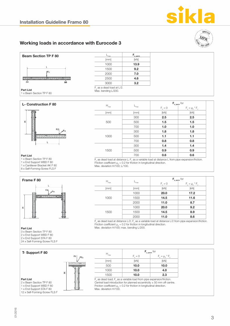
Installation Guideline Framo 80
301/2
016
Working loads in accordance with Eurocode 3
Beam Section TP F 80 Lmax Fz, perm
[mm] [kN]
1000 13.9
1500 9.2
2000 7.0
2500 4.6
3000 3.2
Part List1 x Beam Section TP F 80
Fz as a dead load at L/2.Max. bending L/200.
L- Construction F 80 Hmax Lmax
Fz, perm for
Fx = 0 Fx = µ0 * Fz
[mm] [mm] [kN] [kN]
500
300 2.5 2.5
500 1.5 1.5
700 1.0 1.0
1000
300 1.8 1.8
500 1.1 1.1
700 0.8 0.8
1500
300 1.4 1.4
500 0.9 0.9
Part List1 x Beam Section TP F 801 x End Support WBD F 801 x Cantilever Bracket AK F 808 x Self-Forming-Screw FLS F
700 0.6 0.6Fz as dead load at distance L; Fx as a variable load at distance L from pipe expansion/friction. Friction coefficient µ0 = 0.2 for friction in longitudinal direction.Max. deviation H/100; L/100.
Frame F 80 Hmax Lmax
Fz, perm for
Fx = 0 Fx = µ0 * Fz
[mm] [mm] [kN] [kN]
1000
1000 20.0 17.2
1500 14.5 11.6
2000 11.0 8.7
1500
1000 20.0 9.2
1500 14.5 8.9
2000 11.0 8.6
Part List 3 x Beam Section TP F 802 x End Support WBD F 802 x End Support STA F 8024 x Self-Forming-Screw FLS F
Fz as dead load at distance L/2; Fx as a variable load at distance L/2 from pipe expansion/friction. Friction coefficient µ0 = 0.2 for friction in longitudinal direction.Max. deviation H/100; max. bending L/200.
T- Support F 80 Hmax
Fz, perm for
Fx = 0 Fx = µ0 * Fz
[mm] [kN] [kN]
500 10.0 10.01000 10.0 4.01500 10.0 2.3
Part List 2 x Beam Section TP F 801 x End Support WBD F 801 x End Support STA F 8012 x Self-Forming-Screw FLS F
Fz as dead load; Fx as a variable load from pipe expansion/friction. Central load introduction for planned eccentricity ± 50 mm off-centre. Friction coefficient µ0 = 0.2 for friction in longitudinal direction.Max. deviation H/100.
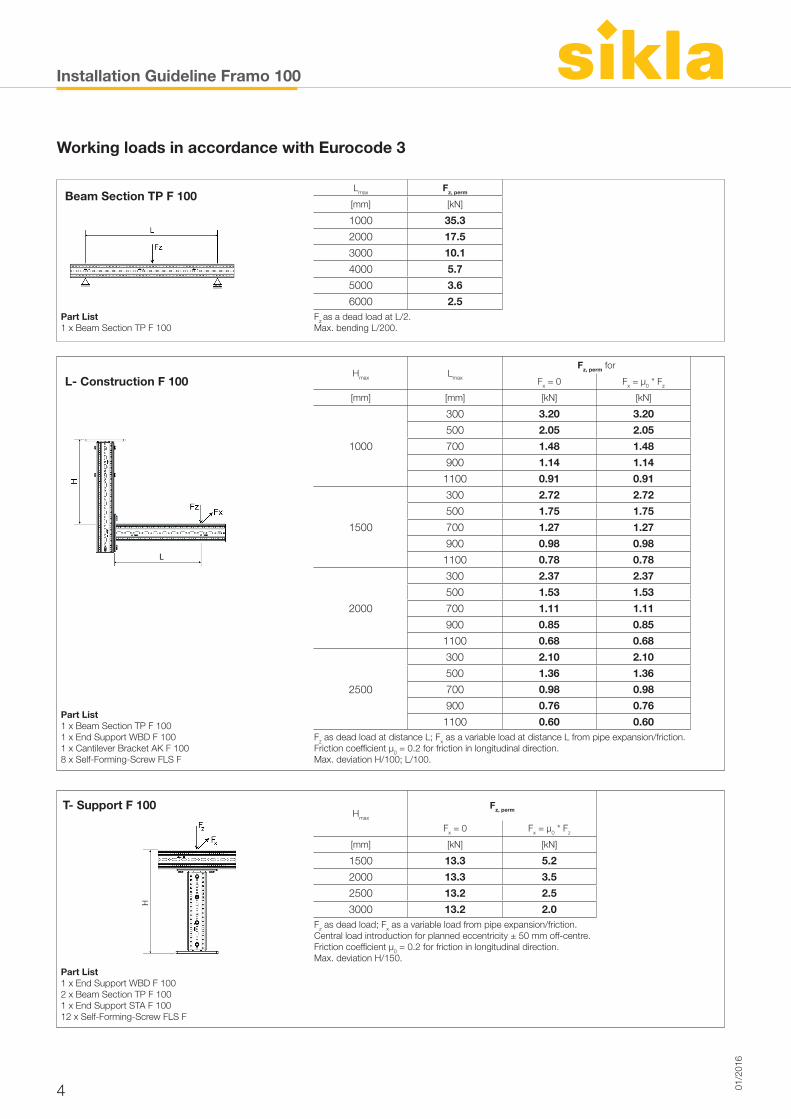
Installation Guideline Framo 100
4 01/2
016
Working loads in accordance with Eurocode 3
Beam Section TP F 100Lmax Fz, perm
[mm] [kN]
1000 35.3
2000 17.5
3000 10.1
4000 5.7
Part List1 x Beam Section TP F 100
5000 3.6
6000 2.5Fz as a dead load at L/2. Max. bending L/200.
L- Construction F 100Hmax Lmax
Fz, perm for
Fx = 0 Fx = µ0 * Fz
[mm] [mm] [kN] [kN]
1000
300 3.20 3.20
500 2.05 2.05
700 1.48 1.48
900 1.14 1.14
1100 0.91 0.91
1500
300 2.72 2.72
500 1.75 1.75
700 1.27 1.27
900 0.98 0.98
1100 0.78 0.78
2000
300 2.37 2.37
500 1.53 1.53
700 1.11 1.11
900 0.85 0.85
1100 0.68 0.68
2500
300 2.10 2.10
500 1.36 1.36
Part List1 x Beam Section TP F 1001 x End Support WBD F 1001 x Cantilever Bracket AK F 1008 x Self-Forming-Screw FLS F
700 0.98 0.98
900 0.76 0.76
1100 0.60 0.60Fz as dead load at distance L; Fx as a variable load at distance L from pipe expansion/friction. Friction coefficient µ0 = 0.2 for friction in longitudinal direction.Max. deviation H/100; L/100.
T- Support F 100Hmax
Fz, perm
Fx = 0 Fx = µ0 * Fz
[mm] [kN] [kN]
1500 13.3 5.2
2000 13.3 3.5
2500 13.2 2.5
3000 13.2 2.0Fz as dead load; Fx as a variable load from pipe expansion/friction. Central load introduction for planned eccentricity ± 50 mm off-centre. Friction coefficient µ0 = 0.2 for friction in longitudinal direction.Max. deviation H/150.
Part List 1 x End Support WBD F 1002 x Beam Section TP F 1001 x End Support STA F 10012 x Self-Forming-Screw FLS F
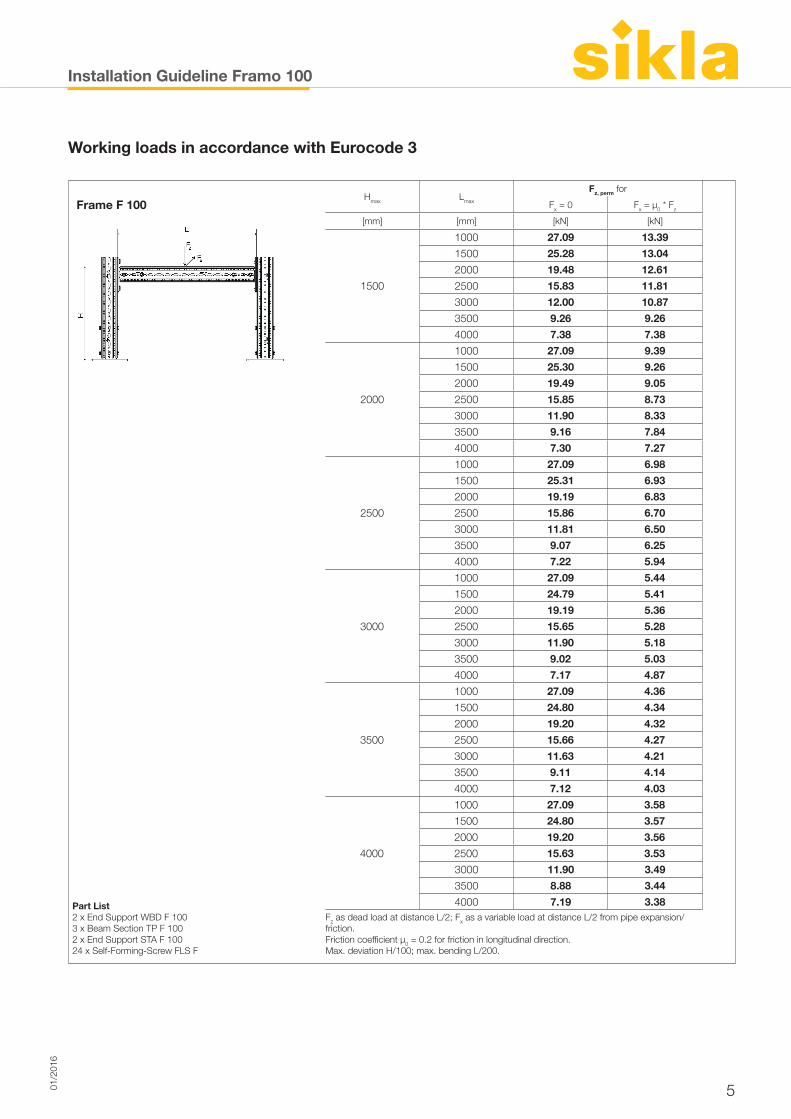
Installation Guideline Framo 100
501/2
016
Working loads in accordance with Eurocode 3
Frame F 100Hmax Lmax
Fz, perm for
Fx = 0 Fx = µ0 * Fz
[mm] [mm] [kN] [kN]
1500
1000 27.09 13.39
1500 25.28 13.04
2000 19.48 12.61
2500 15.83 11.81
3000 12.00 10.87
3500 9.26 9.26
4000 7.38 7.38
2000
1000 27.09 9.39
1500 25.30 9.26
2000 19.49 9.05
2500 15.85 8.73
3000 11.90 8.33
3500 9.16 7.84
4000 7.30 7.27
2500
1000 27.09 6.98
1500 25.31 6.93
2000 19.19 6.83
2500 15.86 6.70
3000 11.81 6.50
3500 9.07 6.25
4000 7.22 5.94
3000
1000 27.09 5.44
1500 24.79 5.41
2000 19.19 5.36
2500 15.65 5.28
3000 11.90 5.18
3500 9.02 5.03
4000 7.17 4.87
3500
1000 27.09 4.36
1500 24.80 4.34
2000 19.20 4.32
2500 15.66 4.27
3000 11.63 4.21
3500 9.11 4.14
4000 7.12 4.03
4000
1000 27.09 3.58
1500 24.80 3.57
2000 19.20 3.56
2500 15.63 3.53
Part List 2 x End Support WBD F 1003 x Beam Section TP F 1002 x End Support STA F 10024 x Self-Forming-Screw FLS F
3000 11.90 3.49
3500 8.88 3.44
4000 7.19 3.38Fz as dead load at distance L/2; Fx as a variable load at distance L/2 from pipe expansion/friction. Friction coefficient µ0 = 0.2 for friction in longitudinal direction.Max. deviation H/100; max. bending L/200.
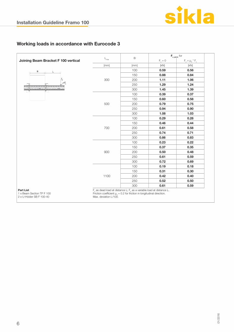
Installation Guideline Framo 100
6 01/2
016
Joining Beam Bracket F 100 verticalLmax B
Fz, perm for
Fx = 0 Fx = µ0 * Fz
[mm] [mm] [kN] [kN]
300
100 0.59 0.56
150 0.88 0.84
200 1.11 1.06
250 1.29 1.24
300 1.45 1.39
500
100 0.39 0.37
150 0.60 0.58
200 0.79 0.75
250 0.94 0.90
300 1.08 1.03
700
100 0.29 0.28
150 0.46 0.44
200 0.61 0.58
250 0.74 0.71
300 0.86 0.83
900
100 0.23 0.22
150 0.37 0.35
Part List 1 x Beam Section TP F 1002 x U-Holder SB F 100-40
200 0.50 0.48
250 0.61 0.59
300 0.72 0.69
1100
100 0.19 0.18
150 0.31 0.30
200 0.42 0.40
250 0.52 0.50
300 0.61 0.59Fz as dead load at distance L; Fx as a variable load at distance L. Friction coefficient µ0 = 0.2 for friction in longitudinal direction.Max. deviation L/100.
Working loads in accordance with Eurocode 3
Installation Guideline Framo 100
701/2
016
Working loads in accordance with Eurocode 3
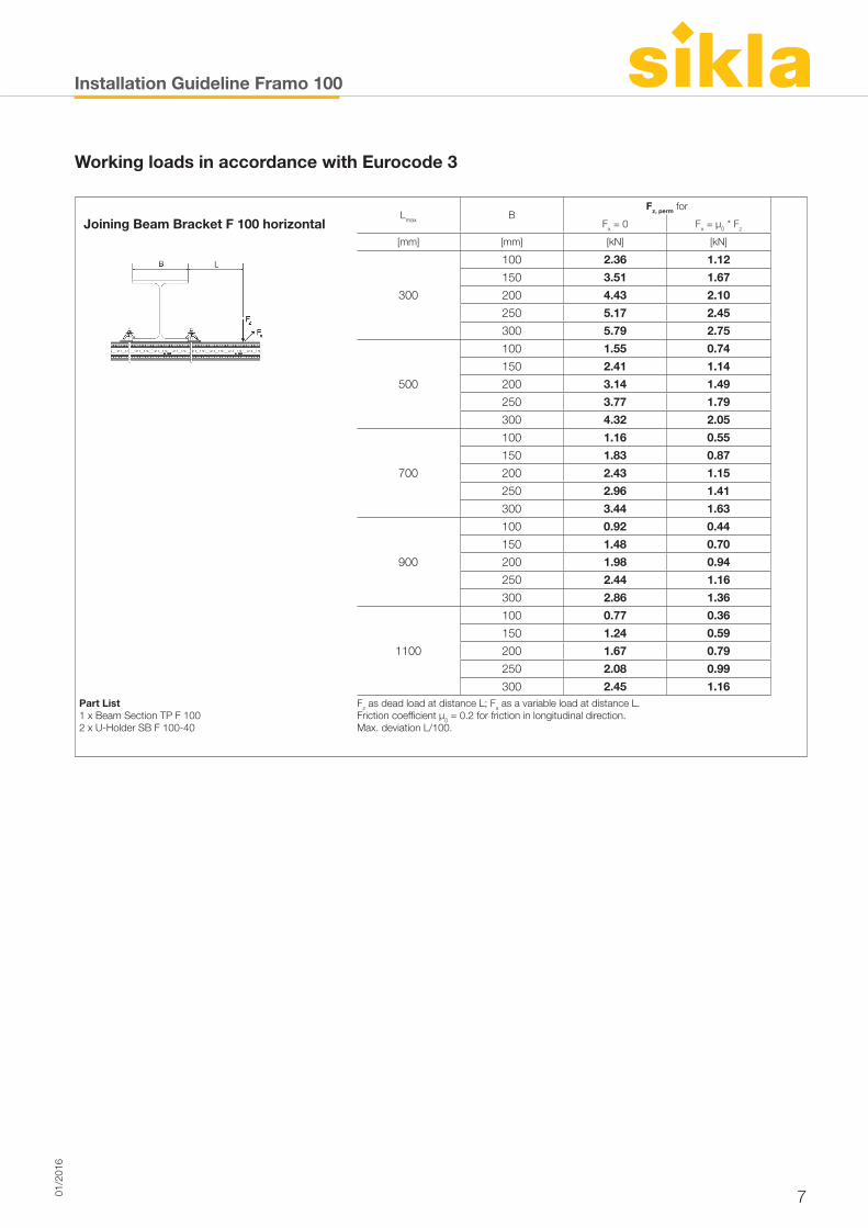
Joining Beam Bracket F 100 horizontalLmax B
Fz, perm for
Fx = 0 Fx = µ0 * Fz
[mm] [mm] [kN] [kN]
300
100 2.36 1.12
150 3.51 1.67
200 4.43 2.10
250 5.17 2.45
300 5.79 2.75
500
100 1.55 0.74
150 2.41 1.14
200 3.14 1.49
250 3.77 1.79
300 4.32 2.05
700
100 1.16 0.55
150 1.83 0.87
200 2.43 1.15
250 2.96 1.41
300 3.44 1.63
900
100 0.92 0.44
150 1.48 0.70
Part List 1 x Beam Section TP F 1002 x U-Holder SB F 100-40
200 1.98 0.94
250 2.44 1.16
300 2.86 1.36
1100
100 0.77 0.36
150 1.24 0.59
200 1.67 0.79
250 2.08 0.99
300 2.45 1.16Fz as dead load at distance L; Fx as a variable load at distance L. Friction coefficient µ0 = 0.2 for friction in longitudinal direction.Max. deviation L/100.
Installation Guideline Framo 100
8 01/2
016
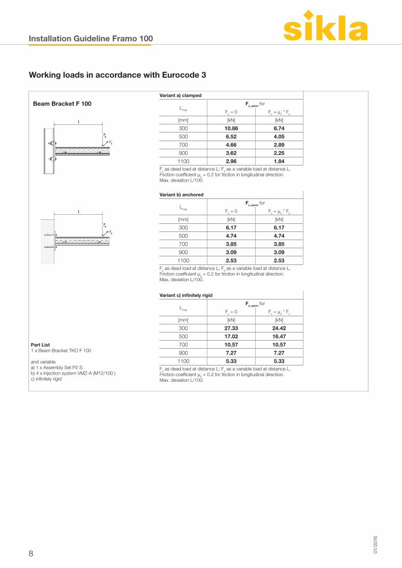
Beam Bracket F 100Variant a) clamped
Lmax
Fz, perm for
Fx = 0 Fx = µ0 * Fz
[mm] [kN] [kN]
300 10.86 6.74
500 6.52 4.05
700 4.66 2.89
900 3.62 2.25
1100 2.96 1.84Fz as dead load at distance L; Fx as a variable load at distance L. Friction coefficient µ0 = 0.2 for friction in longitudinal direction.Max. deviation L/100.
Variant b) anchored
Lmax
Fz, perm for
Fx = 0 Fx = µ0 * Fz
[mm] [kN] [kN]
300 6.17 6.17
500 4.74 4.74
700 3.85 3.85
900 3.09 3.09
1100 2.53 2.53Fz as dead load at distance L; Fx as a variable load at distance L. Friction coefficient µ0 = 0.2 for friction in longitudinal direction.Max. deviation L/100.
Variant c) infinitely rigid
Part List1 x Beam Bracket TKO F 100
and variablea) 1 x Assembly Set P2 S b) 4 x Injection system VMZ-A (M12/100 )c) infinitely rigid
Lmax
Fz, perm for
Fx = 0 Fx = µ0 * Fz
[mm] [kN] [kN]
300 27.33 24.42
500 17.02 16.47
700 10.57 10.57
900 7.27 7.27
1100 5.33 5.33Fz as dead load at distance L; Fx as a variable load at distance L. Friction coefficient µ0 = 0.2 for friction in longitudinal direction.Max. deviation L/100.
Working loads in accordance with Eurocode 3
Installation Guideline Framo 100/160
901/2
016
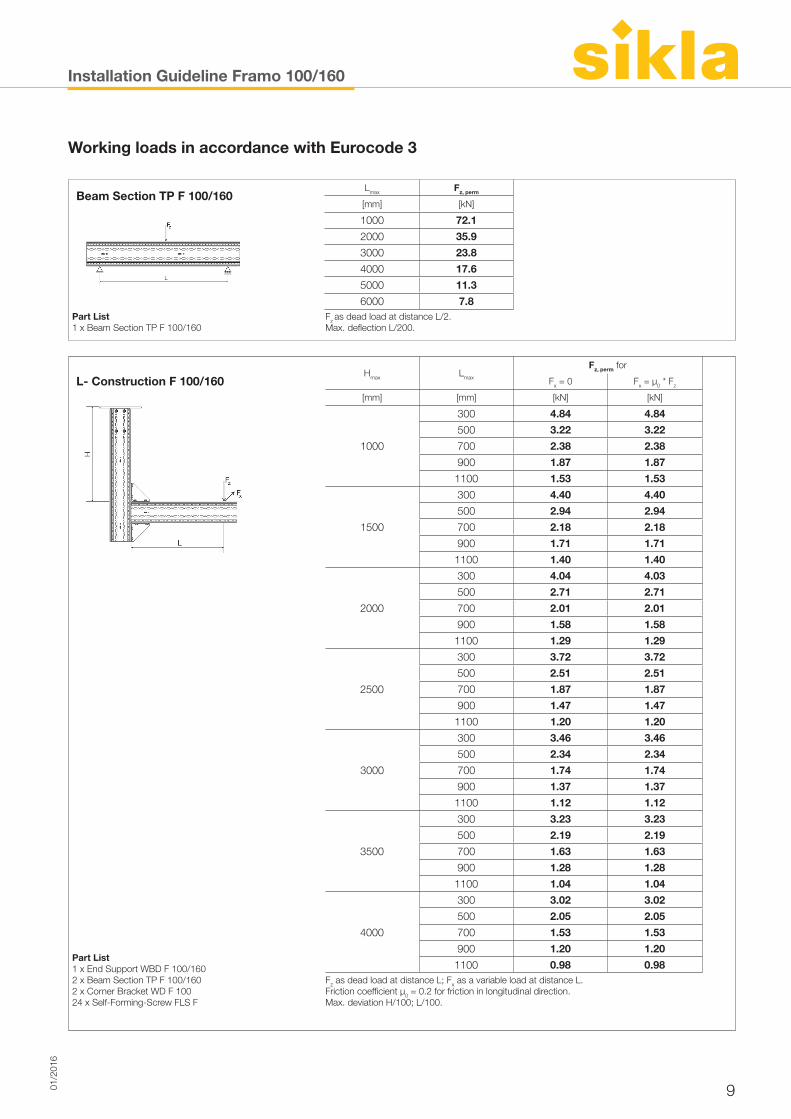
Beam Section TP F 100/160Lmax Fz, perm
[mm] [kN]
1000 72.1
2000 35.9
3000 23.8
4000 17.6
Part List1 x Beam Section TP F 100/160
5000 11.3
6000 7.8Fz as dead load at distance L/2. Max. deflection L/200.
L- Construction F 100/160Hmax Lmax
Fz, perm for
Fx = 0 Fx = µ0 * Fz
[mm] [mm] [kN] [kN]
1000
300 4.84 4.84
500 3.22 3.22
700 2.38 2.38
900 1.87 1.87
1100 1.53 1.53
1500
300 4.40 4.40
500 2.94 2.94
700 2.18 2.18
900 1.71 1.71
1100 1.40 1.40
2000
300 4.04 4.03
500 2.71 2.71
700 2.01 2.01
900 1.58 1.58
1100 1.29 1.29
2500
300 3.72 3.72
500 2.51 2.51
Part List 1 x End Support WBD F 100/1602 x Beam Section TP F 100/1602 x Corner Bracket WD F 10024 x Self-Forming-Screw FLS F
700 1.87 1.87
900 1.47 1.47
1100 1.20 1.20
3000
300 3.46 3.46
500 2.34 2.34
700 1.74 1.74
900 1.37 1.37
1100 1.12 1.12
3500
300 3.23 3.23
500 2.19 2.19
700 1.63 1.63
900 1.28 1.28
1100 1.04 1.04
4000
300 3.02 3.02
500 2.05 2.05
700 1.53 1.53
900 1.20 1.20
1100 0.98 0.98Fz as dead load at distance L; Fx as a variable load at distance L. Friction coefficient µ0 = 0.2 for friction in longitudinal direction.Max. deviation H/100; L/100.
Working loads in accordance with Eurocode 3
Installation Guideline Framo 100/160
10 01/2
016
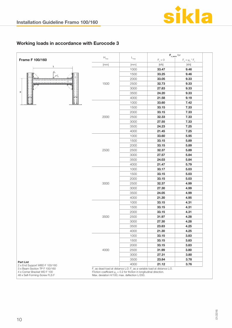
Frame F 100/160Hmax Lmax
Fz, perm for
Fx = 0 Fx = µ0 * Fz
[mm] [mm] [kN] [kN]
1500
1000 33.47 9.46
1500 33.25 9.46
2000 33.05 9.33
2500 32.73 9.33
3000 27.83 9.33
3500 24.20 9.33
4000 21.58 9.19
2000
1000 33.60 7.42
1500 33.15 7.33
2000 33.15 7.33
2500 32.33 7.33
3000 27.55 7.33
3500 24.23 7.25
4000 21.45 7.25
2500
1000 33.60 5.95
1500 33.15 5.89
2000 33.15 5.89
2500 32.37 5.89
3000 27.57 5.84
3500 24.03 5.84
4000 21.47 5.79
3000
1000 33.17 5.03
1500 33.15 5.03
2000 33.15 5.03
2500 32.37 4.99
3000 27.30 4.99
3500 24.05 4.99
4000 21.30 4.95
3500
1000 33.15 4.31
1500 33.15 4.31
2000 33.15 4.31
2500 31.97 4.28
3000 27.30 4.28
3500 23.83 4.25
4000 21.30 4.25
4000
1000 33.15 3.83
1500 33.15 3.83
2000 33.15 3.83
2500 31.99 3.80
Part List 2 x End Support WBD F 100/1603 x Beam Section TP F 100/1604 x Corner Bracket WD F 10048 x Self-Forming-Screw FLS F
3000 27.31 3.80
3500 23.84 3.78
4000 21.12 3.76Fz as dead load at distance L/2; Fx as a variable load at distance L/2. Friction coefficient µ0 = 0.2 for friction in longitudinal direction.Max. deviation H/100; max. deflection L/200.
Working loads in accordance with Eurocode 3
Installation Guideline Framo 100/160
1101/2
016
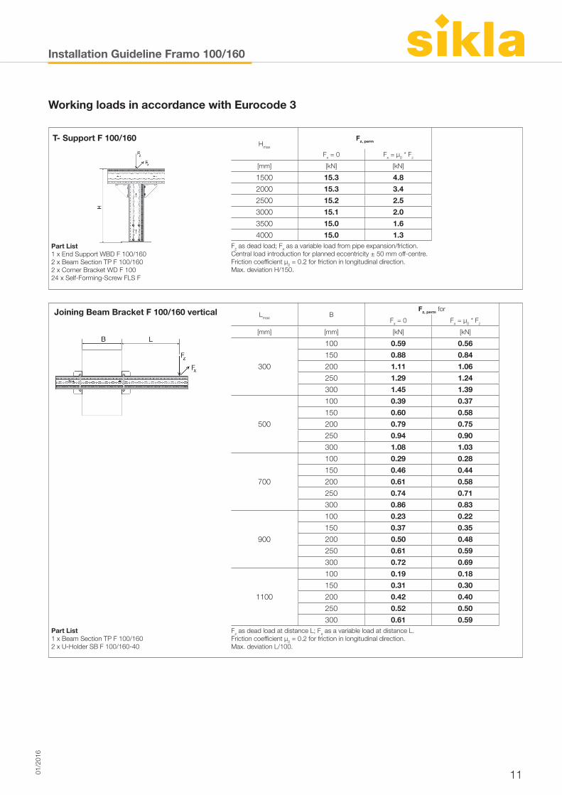
T- Support F 100/160Hmax
Fz, perm
Fx = 0 Fx = µ0 * Fz
[mm] [kN] [kN]
1500 15.3 4.8
2000 15.3 3.4
2500 15.2 2.5
3000 15.1 2.0
3500 15.0 1.6
4000 15.0 1.3Part List 1 x End Support WBD F 100/1602 x Beam Section TP F 100/1602 x Corner Bracket WD F 10024 x Self-Forming-Screw FLS F
Fz as dead load; Fx as a variable load from pipe expansion/friction. Central load introduction for planned eccentricity ± 50 mm off-centre. Friction coefficient µ0 = 0.2 for friction in longitudinal direction.Max. deviation H/150.
Joining Beam Bracket F 100/160 vertical Lmax BFz, perm for
Fx = 0 Fx = µ0 * Fz
[mm] [mm] [kN] [kN]
300
100 0.59 0.56
150 0.88 0.84
200 1.11 1.06
250 1.29 1.24
300 1.45 1.39
500
100 0.39 0.37
150 0.60 0.58
200 0.79 0.75
250 0.94 0.90
300 1.08 1.03
700
100 0.29 0.28
150 0.46 0.44
200 0.61 0.58
250 0.74 0.71
300 0.86 0.83
900
100 0.23 0.22
150 0.37 0.35
Part List 1 x Beam Section TP F 100/1602 x U-Holder SB F 100/160-40
200 0.50 0.48
250 0.61 0.59
300 0.72 0.69
1100
100 0.19 0.18
150 0.31 0.30
200 0.42 0.40
250 0.52 0.50
300 0.61 0.59Fz as dead load at distance L; Fx as a variable load at distance L. Friction coefficient µ0 = 0.2 for friction in longitudinal direction.Max. deviation L/100.
Working loads in accordance with Eurocode 3
Installation Guideline Framo 100/160
12 01/2
016
Working loads in accordance with Eurocode 3
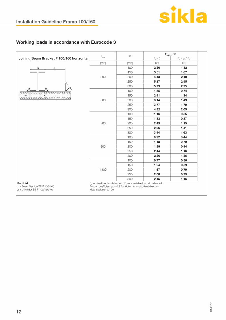
Joining Beam Bracket F 100/160 horizontalLmax B
Fz, perm for
Fx = 0 Fx = µ0 * Fz
[mm] [mm] [kN] [kN]
300
100 2.36 1.12
150 3.51 1.67
200 4.43 2.10
250 5.17 2.45
300 5.79 2.75
500
100 1.55 0.74
150 2.41 1.14
200 3.14 1.49
250 3.77 1.79
300 4.32 2.05
700
100 1.16 0.55
150 1.83 0.87
200 2.43 1.15
250 2.96 1.41
300 3.44 1.63
900
100 0.92 0.44
150 1.48 0.70
Part List 1 x Beam Section TP F 100/1602 x U-Holder SB F 100/160-40
200 1.98 0.94
250 2.44 1.16
300 2.86 1.36
1100
100 0.77 0.36
150 1.24 0.59
200 1.67 0.79
250 2.08 0.99
300 2.45 1.16Fz as dead load at distance L; Fx as a variable load at distance L. Friction coefficient µ0 = 0.2 for friction in longitudinal direction.Max. deviation L/100.
Installation Guideline Framo 100/160
1301/2
016
Working loads in accordance with Eurocode 3
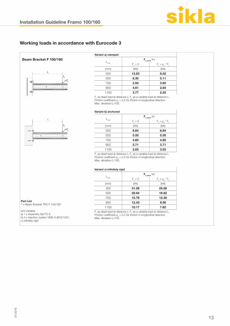
Beam Bracket F 100/160Variant a) clamped
Lmax
Fz, perm for
Fx = 0 Fx = µ0 * Fz
[mm] [kN] [kN]
300 13.83 8.52
500 8.30 5.11
700 5.93 3.65
900 4.61 2.84
1100 3.77 2.32Fz as dead load at distance L; Fx as a variable load at distance L. Friction coefficient µ0 = 0.2 for friction in longitudinal direction.Max. deviation L/100.
Variant b) anchored
Lmax
Fz, perm for
Fx = 0 Fx = µ0 * Fz
[mm] [kN] [kN]
300 6.84 6.84
500 5.50 5.50
700 4.60 4.60
900 3.71 3.71
1100 3.03 3.03Fz as dead load at distance L; Fx as a variable load at distance L. Friction coefficient µ0 = 0.2 for friction in longitudinal direction.Max. deviation L/100.
Variant c) infinitely rigid
Part List1 x Beam Bracket TKO F 100/160
and variablea) 1 x Assembly Set P2 S b) 4 x Injection system VMZ-A (M12/100 )c) infinitely rigid
Lmax
Fz, perm for
Fx = 0 Fx = µ0 * Fz
[mm] [kN] [kN]
300 31.09 25.58
500 20.94 16.92
700 15.79 12.30
900 12.43 9.56
1100 10.17 7.82Fz as dead load at distance L; Fx as a variable load at distance L. Friction coefficient µ0 = 0.2 for friction in longitudinal direction.Max. deviation L/100.
Installation Guideline Framo 100/160 combi
14 01/2
016
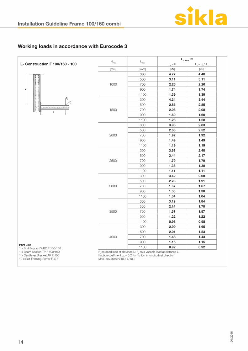
L- Construction F 100/160 - 100Hmax Lmax
Fz, perm for
Fx = 0 Fx = µ0 * Fz
[mm] [mm] [kN] [kN]
1000
300 4.77 4.40
500 3.11 3.11
700 2.26 2.26
900 1.74 1.74
1100 1.39 1.39
1500
300 4.34 3.44
500 2.85 2.85
700 2.08 2.08
900 1.60 1.60
1100 1.28 1.28
2000
300 3.98 2.83
500 2.63 2.52
700 1.92 1.92
900 1.49 1.49
1100 1.19 1.19
2500
300 3.68 2.40
500 2.44 2.17
700 1.79 1.79
900 1.38 1.38
1100 1.11 1.11
3000
300 3.42 2.08
500 2.28 1.91
700 1.67 1.67
900 1.30 1.30
1100 1.04 1.04
3500
300 3.19 1.84
500 2.14 1.70
700 1.57 1.57
900 1.22 1.22
Part List 1 x End Support WBD F 100/1601 x Beam Section TP F 100/1601 x Cantilever Bracket AK F 10012 x Self-Forming-Screw FLS F
1100 0.98 0.98
4000
300 2.99 1.65
500 2.01 1.53
700 1.48 1.43
900 1.15 1.15
1100 0.92 0.92Fz as dead load at distance L; Fx as a variable load at distance L. Friction coefficient µ0 = 0.2 for friction in longitudinal direction.Max. deviation H/100; L/100.
Working loads in accordance with Eurocode 3
Installation Guideline Framo 100/160 combi
1501/2
016
Working loads in accordance with Eurocode 3
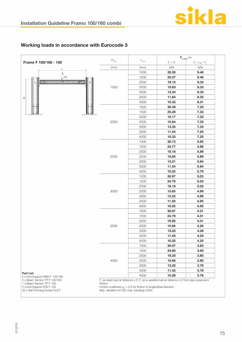
Frame F 100/160 - 100Hmax Lmax
Fz, perm for
Fx = 0 Fx = µ0 * Fz
[mm] [mm] [kN] [kN]
1500
1000 30.26 9.46
1500 25.27 9.46
2000 19.15 9.33
2500 15.63 9.33
3000 13.34 9.33
3500 11.64 9.33
4000 10.32 8.31
2000
1000 30.49 7.33
1500 25.28 7.33
2000 19.17 7.33
2500 15.64 7.33
3000 13.35 7.33
3500 11.54 7.25
4000 10.33 7.25
2500
1000 30.73 5.95
1500 24.77 5.89
2000 19.18 5.89
2500 15.65 5.89
3000 13.21 5.84
3500 11.54 5.84
4000 10.25 5.79
3000
1000 30.97 5.03
1500 24.79 5.03
2000 19.19 5.03
2500 15.65 4.99
3000 13.22 4.99
3500 11.55 4.95
4000 10.25 4.95
3500
1000 30.97 4.31
1500 24.79 4.31
2000 19.20 4.31
2500 15.66 4.28
Part List 2 x End Support WBD F 100/160 2 x Beam Section TP F 100/1601 x Beam Section TP F 1002 x End Support STA F 10032 x Self-Forming-Screw FLS F
3000 13.22 4.28
3500 11.55 4.25
4000 10.25 4.25
4000
1000 30.97 3.83
1500 24.80 3.83
2000 19.20 3.80
2500 15.66 3.80
3000 13.22 3.78
3500 11.55 3.78
4000 10.26 3.76Fz as dead load at distance L/2; Fx as a variable load at distance L/2 from pipe expansion/friction. Friction coefficient µ0 = 0.2 for friction in longitudinal direction.Max. deviation H/100; max. bending L/200.
Installation Guideline Beam System 100
16 01/2
016
Working loads in accordance with Eurocode 3
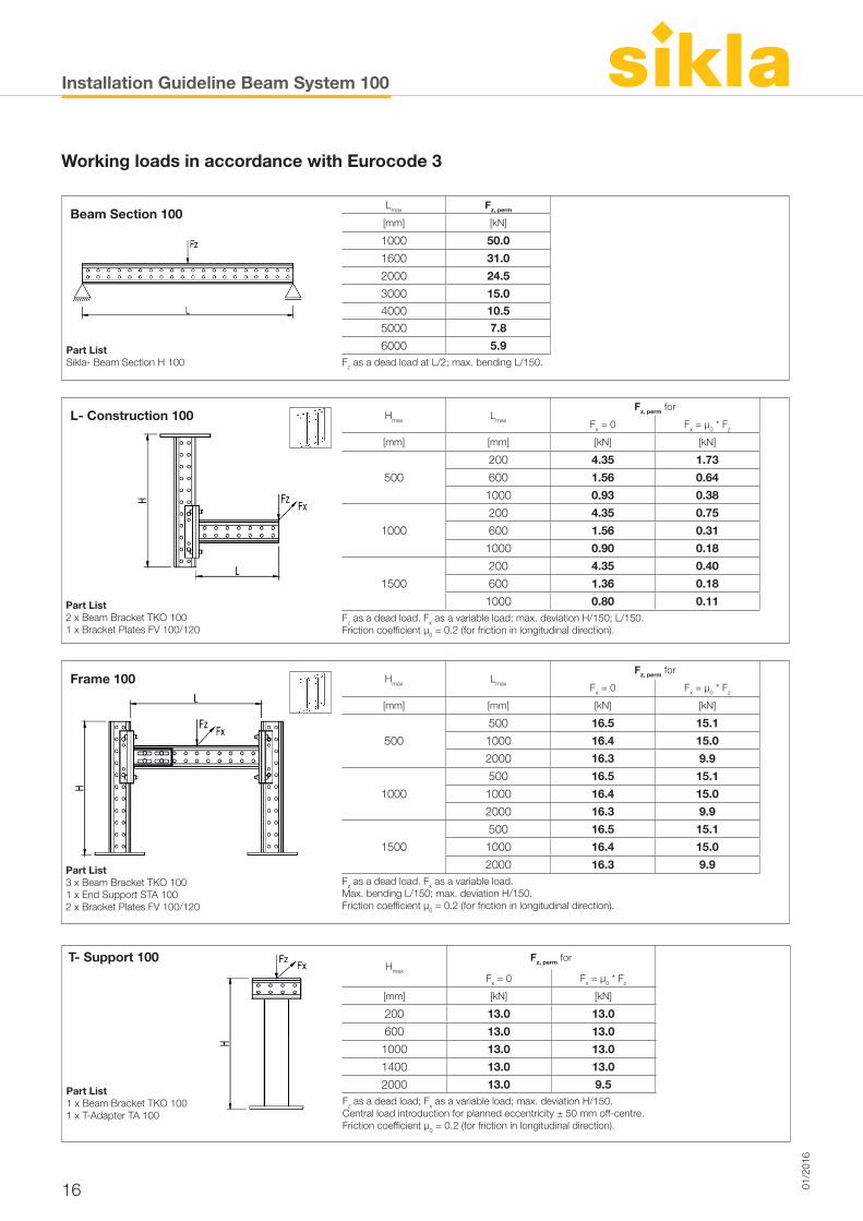
Beam Section 100Lmax Fz, perm
[mm] [kN]
1000 50.0
1600 31.0
2000 24.5
3000 15.04000 10.55000 7.8
Part ListSikla- Beam Section H 100
6000 5.9Fz as a dead load at L/2; max. bending L/150.
L- Construction 100 Hmax Lmax
Fz, perm for
Fx = 0 Fx = µ0 * Fz
[mm] [mm] [kN] [kN]
500
200 4.35 1.73
600 1.56 0.64
1000 0.93 0.38
1000
200 4.35 0.75
600 1.56 0.31
1000 0.90 0.18
1500
200 4.35 0.40
600 1.36 0.18
Part List2 x Beam Bracket TKO 1001 x Bracket Plates FV 100/120
1000 0.80 0.11Fz as a dead load. Fx as a variable load; max. deviation H/150; L/150.Friction coefficient μ0 = 0.2 (for friction in longitudinal direction).
Frame 100 Hmax Lmax
Fz, perm for
Fx = 0 Fx = µ0 * Fz
[mm] [mm] [kN] [kN]
500
500 16.5 15.1
1000 16.4 15.0
2000 16.3 9.9
1000
500 16.5 15.1
1000 16.4 15.0
2000 16.3 9.9
1500
500 16.5 15.1
1000 16.4 15.0
Part List 3 x Beam Bracket TKO 1001 x End Support STA 1002 x Bracket Plates FV 100/120
2000 16.3 9.9Fz as a dead load. Fx as a variable load. Max. bending L/150; max. deviation H/150.Friction coefficient μ0 = 0.2 (for friction in longitudinal direction).
T- Support 100Hmax
Fz, perm for
Fx = 0 Fx = µ0 * Fz
[mm] [kN] [kN]
200 13.0 13.0
600 13.0 13.0
1000 13.0 13.0
1400 13.0 13.0
Part List1 x Beam Bracket TKO 1001 x T-Adapter TA 100
2000 13.0 9.5Fz as a dead load; Fx as a variable load; max. deviation H/150.Central load introduction for planned eccentricity ± 50 mm off-centre. Friction coefficient μ0 = 0.2 (for friction in longitudinal direction).
Installation Guideline Beam System 100
1701/2
016
Working loads in accordance with Eurocode 3
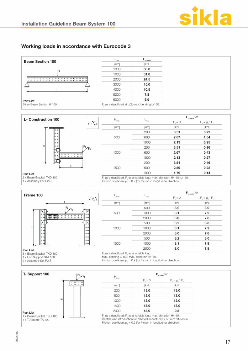
Beam Section 100Lmax Fz, perm
[mm] [kN]
1000 50.0
1600 31.0
2000 24.5
3000 15.0
4000 10.5
5000 7.8
Part ListSikla- Beam Section H 100
6000 5.9Fz as a dead load at L/2; max. bending L/150.
L- Construction 100 Hmax Lmax
Fz, perm for
Fx = 0 Fx = µ0 * Fz
[mm] [mm] [kN] [kN]
500
200 3.51 3.22
600 2.67 1.54
1000 2.13 0.95
1000
200 3.51 0.96
600 2.67 0.43
1000 2.13 0.27
1500
200 3.51 0.46
600 2.59 0.22
Part List2 x Beam Bracket TKO 1001 x Assembly Set P2 S
1000 1.79 0.14Fz as a dead load. Fx as a variable load; max. deviation H/150; L/150.Friction coefficient μ0 = 0.2 (for friction in longitudinal direction).
Frame 100 Hmax Lmax
Fz, perm for
Fx = 0 Fx = µ0 * Fz
[mm] [mm] [kN] [kN]
500
500 8.2 8.0
1000 8.1 7.9
2000 8.0 7.8
1000
500 8.2 8.0
1000 8.1 7.9
2000 8.0 7.8
1500
500 8.2 8.0
1000 8.1 7.9
Part List 3 x Beam Bracket TKO 1001 x End Support STA 1002 x Assembly Set P2 S
2000 8.0 7.8Fz as a dead load. Fx as a variable load. Max. bending L/150; max. deviation H/150.Friction coefficient μ0 = 0.2 (for friction in longitudinal direction).
T- Support 100Hmax
Fz, perm for
Fx = 0 Fx = µ0 * Fz
[mm] [kN] [kN]
200 13.0 13.0
600 13.0 13.0
1000 13.0 13.0
1400 13.0 13.0
Part List1 x Beam Bracket TKO 1001 x T-Adapter TA 100
2000 13.0 9.5Fz as a dead load; Fx as a variable load; max. deviation H/150.Central load introduction for planned eccentricity ± 50 mm off-centre. Friction coefficient μ0 = 0.2 (for friction in longitudinal direction).
Installation Guideline Beam System 100
18 01/2
016
Working loads in accordance with Eurocode 3
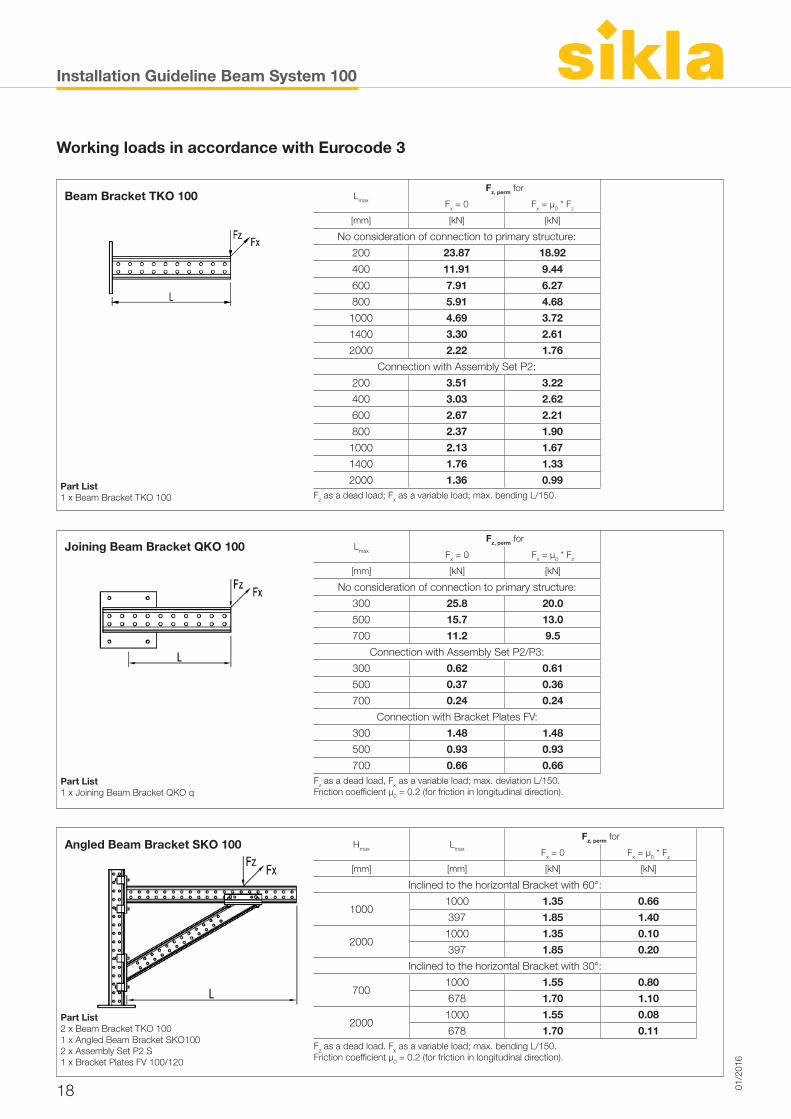
Beam Bracket TKO 100 Lmax
Fz, perm for
Fx = 0 Fx = µ0 * Fz
[mm] [kN] [kN]
No consideration of connection to primary structure:
200 23.87 18.92
400 11.91 9.44
600 7.91 6.27
800 5.91 4.68
1000 4.69 3.72
1400 3.30 2.61
Part List1 x Beam Bracket TKO 100
2000 2.22 1.76
Connection with Assembly Set P2:
200 3.51 3.22
400 3.03 2.62
600 2.67 2.21
800 2.37 1.90
1000 2.13 1.67
1400 1.76 1.33
2000 1.36 0.99Fz as a dead load; Fx as a variable load; max. bending L/150.
Joining Beam Bracket QKO 100 Lmax
Fz, perm for
Fx = 0 Fx = µ0 * Fz
[mm] [kN] [kN]
No consideration of connection to primary structure:
300 25.8 20.0
500 15.7 13.0
700 11.2 9.5
Connection with Assembly Set P2/P3:
300 0.62 0.61
500 0.37 0.36
Part List1 x Joining Beam Bracket QKO q
700 0.24 0.24
Connection with Bracket Plates FV:
300 1.48 1.48
500 0.93 0.93
700 0.66 0.66Fz as a dead load, Fx as a variable load; max. deviation L/150.Friction coefficient μ0 = 0.2 (for friction in longitudinal direction).
Angled Beam Bracket SKO 100 Hmax Lmax
Fz, perm for
Fx = 0 Fx = µ0 * Fz
[mm] [mm] [kN] [kN]
Inclined to the horizontal Bracket with 60°:
10001000 1.35 0.66
397 1.85 1.40
20001000 1.35 0.10
397 1.85 0.20
Inclined to the horizontal Bracket with 30°:
7001000 1.55 0.80
Part List 2 x Beam Bracket TKO 1001 x Angled Beam Bracket SKO1002 x Assembly Set P2 S1 x Bracket Plates FV 100/120
678 1.70 1.10
20001000 1.55 0.08
678 1.70 0.11Fz as a dead load. Fx as a variable load; max. bending L/150.Friction coefficient μ0 = 0.2 (for friction in longitudinal direction).
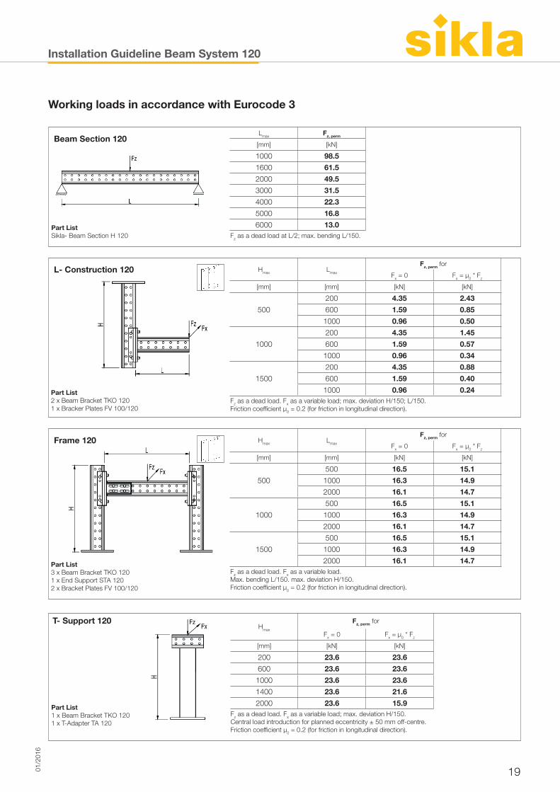
Installation Guideline Beam System 120
1901/2
016
Working loads in accordance with Eurocode 3
Beam Section 120Lmax Fz, perm
[mm] [kN]
1000 98.5
1600 61.5
2000 49.5
3000 31.5
4000 22.3
5000 16.8
Part ListSikla- Beam Section H 120
6000 13.0Fz as a dead load at L/2; max. bending L/150.
L- Construction 120 Hmax Lmax
Fz, perm for
Fx = 0 Fx = µ0 * Fz
[mm] [mm] [kN] [kN]
500
200 4.35 2.43
600 1.59 0.85
1000 0.96 0.50
1000
200 4.35 1.45
600 1.59 0.57
1000 0.96 0.34
1500
200 4.35 0.88
600 1.59 0.40
Part List2 x Beam Bracket TKO 1201 x Bracker Plates FV 100/120
1000 0.96 0.24Fz as a dead load. Fx as a variable load; max. deviation H/150; L/150.Friction coefficient μ0 = 0.2 (for friction in longitudinal direction).
Frame 120 Hmax Lmax
Fz, perm for
Fx = 0 Fx = µ0 * Fz
[mm] [mm] [kN] [kN]
500
500 16.5 15.1
1000 16.3 14.9
2000 16.1 14.7
1000
500 16.5 15.1
1000 16.3 14.9
2000 16.1 14.7
1500
500 16.5 15.1
1000 16.3 14.9
Part List 3 x Beam Bracket TKO 1201 x End Support STA 1202 x Bracket Plates FV 100/120
2000 16.1 14.7Fz as a dead load. Fx as a variable load. Max. bending L/150. max. deviation H/150.Friction coefficient μ0 = 0.2 (for friction in longitudinal direction).
T- Support 120Hmax
Fz, perm for
Fx = 0 Fx = µ0 * Fz
[mm] [kN] [kN]
200 23.6 23.6
600 23.6 23.6
1000 23.6 23.6
1400 23.6 21.6
Part List1 x Beam Bracket TKO 1201 x T-Adapter TA 120
2000 23.6 15.9Fz as a dead load. Fx as a variable load; max. deviation H/150.Central load introduction for planned eccentricity ± 50 mm off-centre. Friction coefficient μ0 = 0.2 (for friction in longitudinal direction).
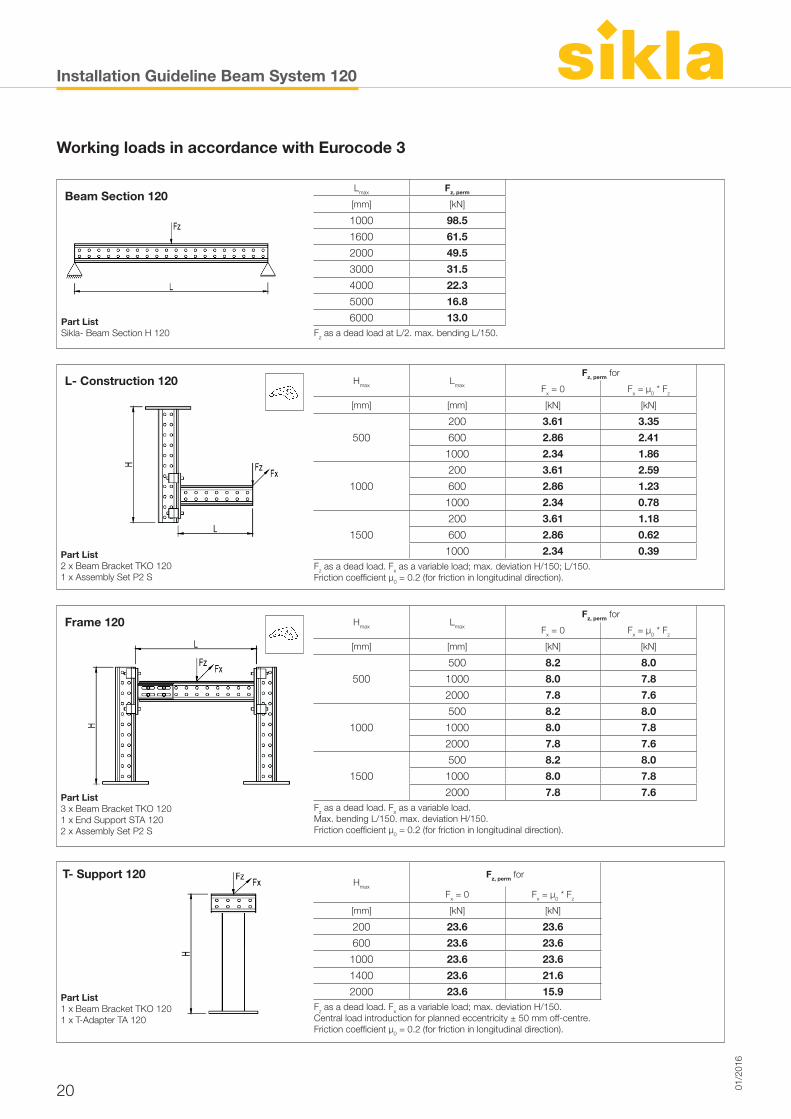
Installation Guideline Beam System 120
20 01/2
016
Working loads in accordance with Eurocode 3
Beam Section 120Lmax Fz, perm
[mm] [kN]
1000 98.5
1600 61.5
2000 49.5
3000 31.5
4000 22.3
5000 16.8
Part ListSikla- Beam Section H 120
6000 13.0Fz as a dead load at L/2. max. bending L/150.
L- Construction 120 Hmax Lmax
Fz, perm for
Fx = 0 Fx = µ0 * Fz
[mm] [mm] [kN] [kN]
500
200 3.61 3.35
600 2.86 2.41
1000 2.34 1.86
1000
200 3.61 2.59
600 2.86 1.23
1000 2.34 0.78
1500
200 3.61 1.18
600 2.86 0.62
Part List2 x Beam Bracket TKO 1201 x Assembly Set P2 S
1000 2.34 0.39Fz as a dead load. Fx as a variable load; max. deviation H/150; L/150.Friction coefficient μ0 = 0.2 (for friction in longitudinal direction).
Frame 120 Hmax Lmax
Fz, perm for
Fx = 0 Fx = µ0 * Fz
[mm] [mm] [kN] [kN]
500
500 8.2 8.0
1000 8.0 7.8
2000 7.8 7.6
1000
500 8.2 8.0
1000 8.0 7.8
2000 7.8 7.6
1500
500 8.2 8.0
1000 8.0 7.8
Part List 3 x Beam Bracket TKO 1201 x End Support STA 1202 x Assembly Set P2 S
2000 7.8 7.6Fz as a dead load. Fx as a variable load. Max. bending L/150. max. deviation H/150.Friction coefficient μ0 = 0.2 (for friction in longitudinal direction).
T- Support 120Hmax
Fz, perm for
Fx = 0 Fx = µ0 * Fz
[mm] [kN] [kN]
200 23.6 23.6
600 23.6 23.6
1000 23.6 23.6
1400 23.6 21.6
Part List1 x Beam Bracket TKO 1201 x T-Adapter TA 120
2000 23.6 15.9Fz as a dead load. Fx as a variable load; max. deviation H/150.Central load introduction for planned eccentricity ± 50 mm off-centre. Friction coefficient μ0 = 0.2 (for friction in longitudinal direction).
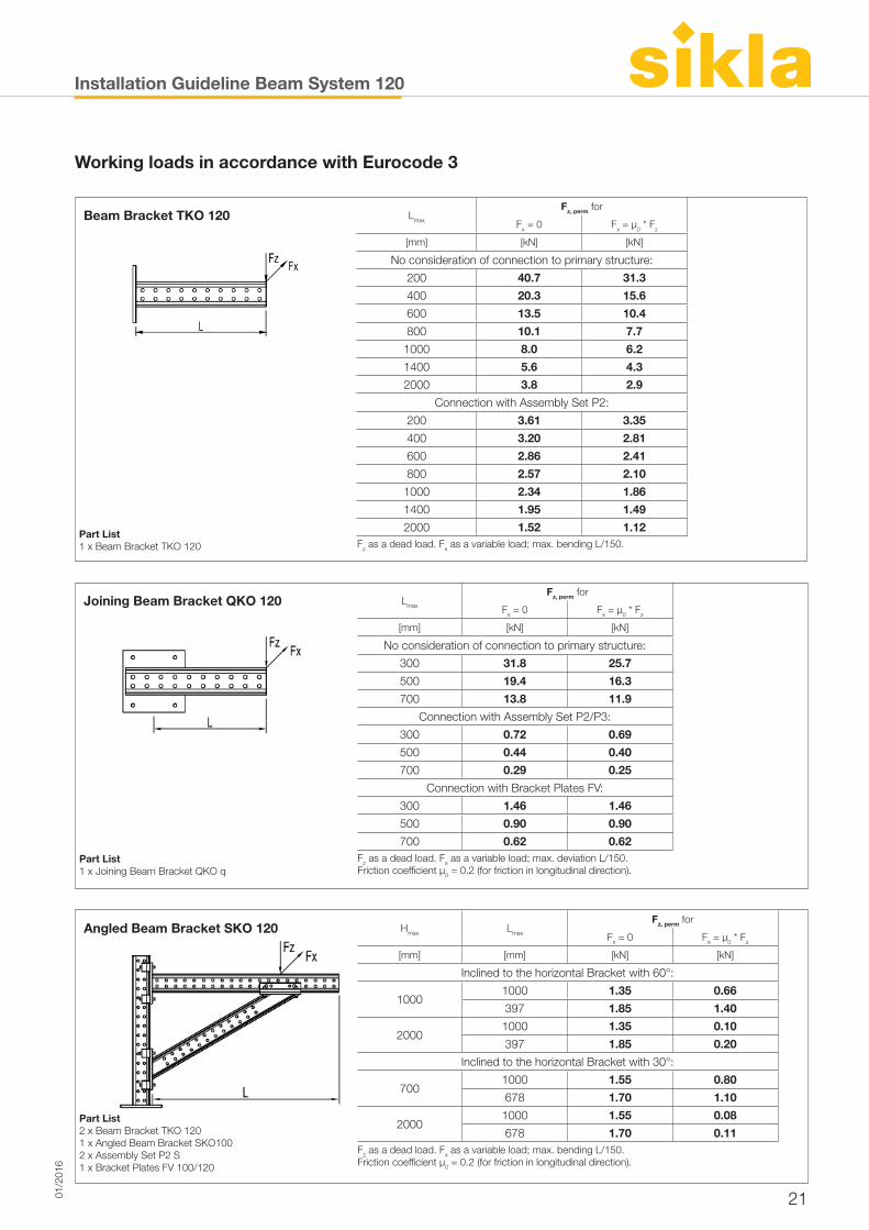
Installation Guideline Beam System 120
2101/2
016
Working loads in accordance with Eurocode 3
Beam Bracket TKO 120 Lmax
Fz, perm for
Fx = 0 Fx = µ0 * Fz
[mm] [kN] [kN]
No consideration of connection to primary structure:
200 40.7 31.3
400 20.3 15.6
600 13.5 10.4
800 10.1 7.7
1000 8.0 6.2
1400 5.6 4.3
Part List1 x Beam Bracket TKO 120
2000 3.8 2.9
Connection with Assembly Set P2:
200 3.61 3.35
400 3.20 2.81
600 2.86 2.41
800 2.57 2.10
1000 2.34 1.86
1400 1.95 1.49
2000 1.52 1.12Fz as a dead load. Fx as a variable load; max. bending L/150.
Joining Beam Bracket QKO 120 Lmax
Fz, perm for
Fx = 0 Fx = µ0 * Fz
[mm] [kN] [kN]
No consideration of connection to primary structure:
300 31.8 25.7
500 19.4 16.3
700 13.8 11.9
Connection with Assembly Set P2/P3:
300 0.72 0.69
500 0.44 0.40
Part List1 x Joining Beam Bracket QKO q
700 0.29 0.25
Connection with Bracket Plates FV:
300 1.46 1.46
500 0.90 0.90
700 0.62 0.62Fz as a dead load. Fx as a variable load; max. deviation L/150.Friction coefficient μ0 = 0.2 (for friction in longitudinal direction).
Angled Beam Bracket SKO 120 Hmax Lmax
Fz, perm for
Fx = 0 Fx = µ0 * Fz
[mm] [mm] [kN] [kN]
Inclined to the horizontal Bracket with 60°:
10001000 1.35 0.66
397 1.85 1.40
20001000 1.35 0.10
397 1.85 0.20
Inclined to the horizontal Bracket with 30°:
7001000 1.55 0.80
Part List2 x Beam Bracket TKO 1201 x Angled Beam Bracket SKO1002 x Assembly Set P2 S1 x Bracket Plates FV 100/120
678 1.70 1.10
20001000 1.55 0.08
678 1.70 0.11Fz as a dead load. Fx as a variable load; max. bending L/150.Friction coefficient μ0 = 0.2 (for friction in longitudinal direction).
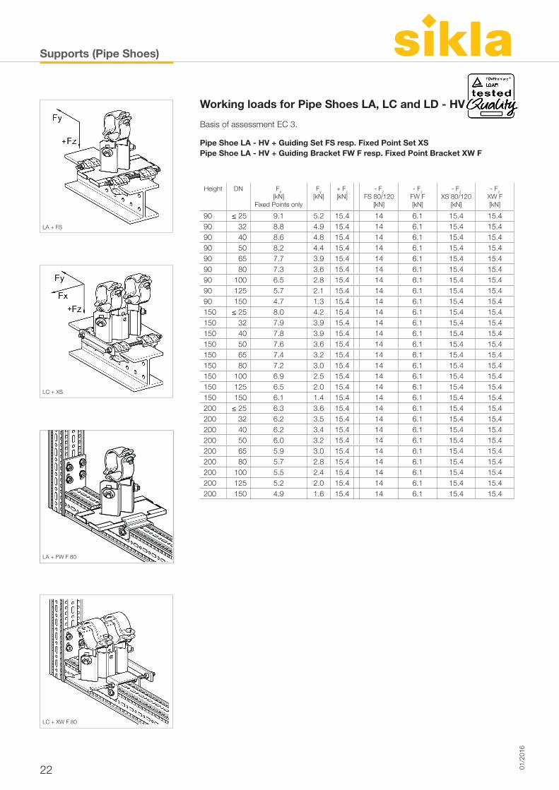
Supports (Pipe Shoes)
22 01/2
016
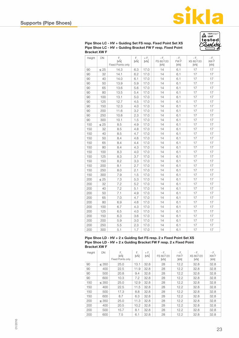
Working loads for Pipe Shoes LA, LC and LD - HV
Basis of assessment EC 3.
Pipe Shoe LA - HV + Guiding Set FS resp. Fixed Point Set XSPipe Shoe LA - HV + Guiding Bracket FW F resp. Fixed Point Bracket XW F
Height DN Fx
[kN]Fixed Points only
Fy
[kN]+ Fz
[kN]- Fz
FS 80/120 [kN]
- Fz
FW F [kN]
- Fz
XS 80/120 [kN]
- Fz
XW F [kN]
90 ≤ 25 9.1 5.2 15.4 14 6.1 15.4 15.490 32 8.8 4.9 15.4 14 6.1 15.4 15.490 40 8.6 4.8 15.4 14 6.1 15.4 15.490 50 8.2 4.4 15.4 14 6.1 15.4 15.490 65 7.7 3.9 15.4 14 6.1 15.4 15.490 80 7.3 3.6 15.4 14 6.1 15.4 15.490 100 6.5 2.8 15.4 14 6.1 15.4 15.490 125 5.7 2.1 15.4 14 6.1 15.4 15.490 150 4.7 1.3 15.4 14 6.1 15.4 15.4150 ≤ 25 8.0 4.2 15.4 14 6.1 15.4 15.4150 32 7.9 3.9 15.4 14 6.1 15.4 15.4150 40 7.8 3.9 15.4 14 6.1 15.4 15.4150 50 7.6 3.6 15.4 14 6.1 15.4 15.4150 65 7.4 3.2 15.4 14 6.1 15.4 15.4150 80 7.2 3.0 15.4 14 6.1 15.4 15.4150 100 6.9 2.5 15.4 14 6.1 15.4 15.4150 125 6.5 2.0 15.4 14 6.1 15.4 15.4150 150 6.1 1.4 15.4 14 6.1 15.4 15.4200 ≤ 25 6.3 3.6 15.4 14 6.1 15.4 15.4200 32 6.2 3.5 15.4 14 6.1 15.4 15.4200 40 6.2 3.4 15.4 14 6.1 15.4 15.4200 50 6.0 3.2 15.4 14 6.1 15.4 15.4200 65 5.9 3.0 15.4 14 6.1 15.4 15.4200 80 5.7 2.8 15.4 14 6.1 15.4 15.4200 100 5.5 2.4 15.4 14 6.1 15.4 15.4200 125 5.2 2.0 15.4 14 6.1 15.4 15.4200 150 4.9 1.6 15.4 14 6.1 15.4 15.4
LA + FS
LC + XS
LC + XW F 80
LA + FW F 80
Supports (Pipe Shoes)
2301/2
016
Height DN Fx
[kN]Fixed Points only
Fy
[kN]+ Fz
[kN]- Fz
FS 80/120 [kN]
- Fz
FW F [kN]
- Fz
XS 80/120 [kN]
- Fz
XW F [kN]
90 ≤ 25 14.3 6.3 17.0 14 6.1 17 1790 32 14.1 6.2 17.0 14 6.1 17 1790 40 14.0 6.1 17.0 14 6.1 17 1790 50 13.9 5.9 17.0 14 6.1 17 1790 65 13.6 5.6 17.0 14 6.1 17 1790 80 13.5 5.4 17.0 14 6.1 17 1790 100 13.1 5.0 17.0 14 6.1 17 1790 125 12.7 4.5 17.0 14 6.1 17 1790 150 12.3 4.0 17.0 14 6.1 17 1790 200 11.6 3.2 17.0 14 6.1 17 1790 250 10.8 2.3 17.0 14 6.1 17 1790 300 10.1 1.5 17.0 14 6.1 17 17150 ≤ 25 8.5 4.9 17.0 14 6.1 17 17150 32 8.5 4.8 17.0 14 6.1 17 17150 40 8.5 4.7 17.0 14 6.1 17 17150 50 8.4 4.6 17.0 14 6.1 17 17150 65 8.4 4.4 17.0 14 6.1 17 17150 80 8.4 4.3 17.0 14 6.1 17 17150 100 8.3 4.0 17.0 14 6.1 17 17150 125 8.3 3.7 17.0 14 6.1 17 17150 150 8.2 3.3 17.0 14 6.1 17 17150 200 8.1 2.7 17.0 14 6.1 17 17150 250 8.0 2.1 17.0 14 6.1 17 17150 300 7.9 1.5 17.0 14 6.1 17 17200 ≤ 25 7.3 5.3 17.0 14 6.1 17 17200 32 7.2 5.2 17.0 14 6.1 17 17200 40 7.2 5.1 17.0 14 6.1 17 17200 50 7.1 4.9 17.0 14 6.1 17 17200 65 7.0 4.7 17.0 14 6.1 17 17200 80 6.9 4.6 17.0 14 6.1 17 17200 100 6.7 4.3 17.0 14 6.1 17 17200 125 6.5 4.0 17.0 14 6.1 17 17200 150 6.3 3.6 17.0 14 6.1 17 17200 200 5.9 3.0 17.0 14 6.1 17 17200 250 5.5 2.3 17.0 14 6.1 17 17200 300 5.1 1.7 17.0 14 6.1 17 17
Height DN Fx
[kN]Fixed Points only
Fy
[kN]+ Fz
[kN]- Fz
FS 80/120 [kN]
- Fz
FW F [kN]
- Fz
XS 80/120 [kN]
- Fz
XW F [kN]
90 ≤ 350 25.0 13.1 32.8 28 12.2 32.8 32.890 400 22.5 11.9 32.8 28 12.2 32.8 32.890 500 20.8 9.4 32.8 28 12.2 32.8 32.890 600 10.3 7.2 32.8 28 12.2 32.8 32.8150 ≤ 350 25.0 12.9 32.8 28 12.2 32.8 32.8150 400 22.5 11.5 32.8 28 12.2 32.8 32.8150 500 17.3 8.8 32.8 28 12.2 32.8 32.8150 600 8.7 6.3 32.8 28 12.2 32.8 32.8200 ≤ 350 25.0 11.3 32.8 28 12.2 32.8 32.8200 400 20.5 10.2 32.8 28 12.2 32.8 32.8200 500 15.7 8.1 32.8 28 12.2 32.8 32.8200 600 7.5 6.1 32.8 28 12.2 32.8 32.8
Pipe Shoe LC - HV + Guiding Set FS resp. Fixed Point Set XSPipe Shoe LC - HV + Guiding Bracket FW F resp. Fixed PointBracket XW F
Pipe Shoe LD - HV + 2 x Guiding Set FS resp. 2 x Fixed Point Set XSPipe Shoe LD - HV + 2 x Guiding Bracket FW F resp. 2 x Fixed PointBracket XW F
Supports (Pipe Shoes)
24 01/2
016
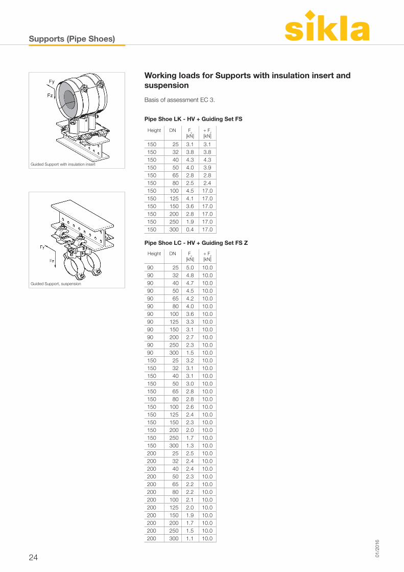
Working loads for Supports with insulation insert and suspension
Basis of assessment EC 3.
Pipe Shoe LK - HV + Guiding Set FS
Pipe Shoe LC - HV + Guiding Set FS Z
Height DN Fy
[kN]+ Fz
[kN]
150 25 3.1 3.1150 32 3.8 3.8150 40 4.3 4.3150 50 4.0 3.9150 65 2.8 2.8150 80 2.5 2.4150 100 4.5 17.0150 125 4.1 17.0150 150 3.6 17.0150 200 2.8 17.0150 250 1.9 17.0150 300 0.4 17.0
Height DN Fy
[kN]+ Fz
[kN]
90 25 5.0 10.090 32 4.8 10.090 40 4.7 10.090 50 4.5 10.090 65 4.2 10.090 80 4.0 10.090 100 3.6 10.090 125 3.3 10.090 150 3.1 10.090 200 2.7 10.090 250 2.3 10.090 300 1.5 10.0150 25 3.2 10.0150 32 3.1 10.0150 40 3.1 10.0150 50 3.0 10.0150 65 2.8 10.0150 80 2.8 10.0150 100 2.6 10.0150 125 2.4 10.0150 150 2.3 10.0150 200 2.0 10.0150 250 1.7 10.0 150 300 1.3 10.0200 25 2.5 10.0200 32 2.4 10.0200 40 2.4 10.0200 50 2.3 10.0200 65 2.2 10.0200 80 2.2 10.0200 100 2.1 10.0200 125 2.0 10.0200 150 1.9 10.0200 200 1.7 10.0200 250 1.5 10.0200 300 1.1 10.0
Guided Support with insulation insert
Guided Support, suspension
Technical Information
2501/2
016
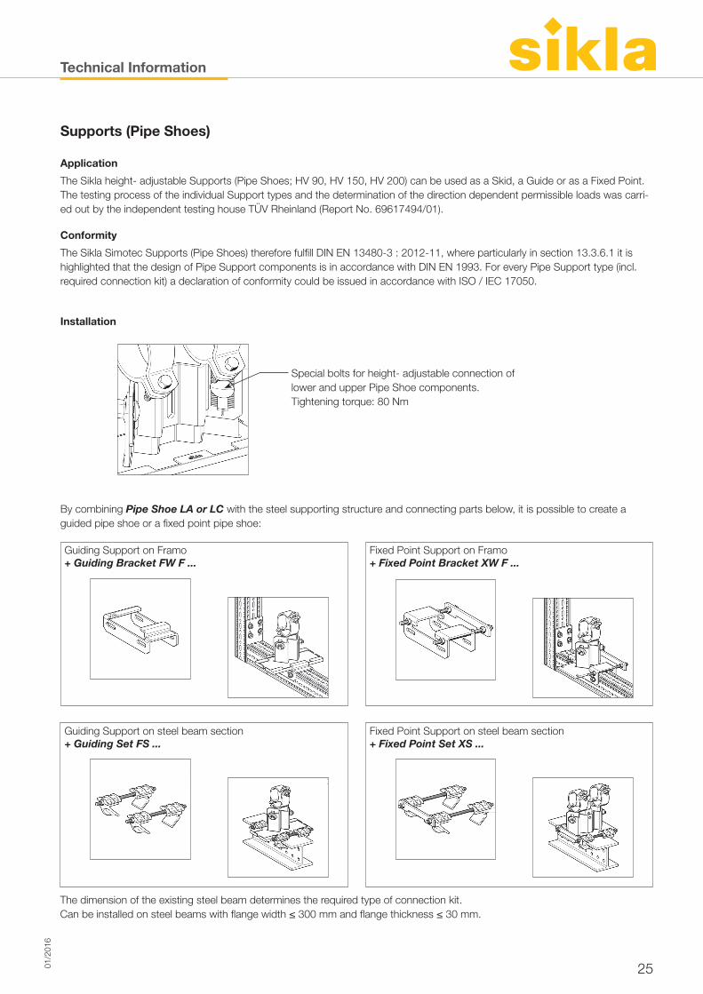
Supports (Pipe Shoes)
Application
The Sikla height- adjustable Supports (Pipe Shoes; HV 90, HV 150, HV 200) can be used as a Skid, a Guide or as a Fixed Point. The testing process of the individual Support types and the determination of the direction dependent permissible loads was carri-ed out by the independent testing house TÜV Rheinland (Report No. 69617494/01).
Conformity
The Sikla Simotec Supports (Pipe Shoes) therefore fulfill DIN EN 13480-3 : 2012-11, where particularly in section 13.3.6.1 it is highlighted that the design of Pipe Support components is in accordance with DIN EN 1993. For every Pipe Support type (incl. required connection kit) a declaration of conformity could be issued in accordance with ISO / IEC 17050.
Installation
By combining Pipe Shoe LA or LC with the steel supporting structure and connecting parts below, it is possible to create a guided pipe shoe or a fixed point pipe shoe:
Special bolts for height- adjustable connection oflower and upper Pipe Shoe components. Tightening torque: 80 Nm
Guiding Support on Framo + Guiding Bracket FW F ...
The dimension of the existing steel beam determines the required type of connection kit. Can be installed on steel beams with flange width ≤ 300 mm and flange thickness ≤ 30 mm.
Fixed Point Support on Framo + Fixed Point Bracket XW F ...
Guiding Support on steel beam section + Guiding Set FS ...
Fixed Point Support on steel beam section + Fixed Point Set XS ...
Technical Information
26 01/2
016
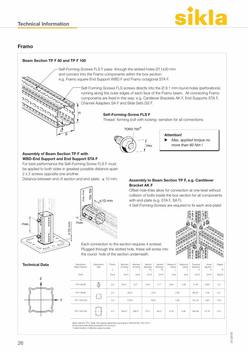
Framo
Beam Section TP F 80 and TP F 100
Technical Data
Self-Forming-Screws FLS F pass- through the slotted holes Ø11x30 mm and connect into the Framo components within the box section: e.g. Framo square End Support WBD F and Framo octagonal STA F.
Self-Forming-Screws FLS screws directly into the Ø 9.1 mm round-holes (perforations) running along the outer edges of each face of the Framo beam. All connecting Framo components are fi xed in this way: e.g. Cantilever Brackets AK F, End Supports STA F, Channel Adapters SA F and Slide Sets GS F.
Assembly of Beam Section TP F withWBD-End Support and End Support STA FFor best performance the Self-Forming-Screw FLS F must be applied to both sides in greatest possible distance apart 2 x 2 screws opposite one another. Distance between end of section and end-plate: ≤ 10 mm. Assembly to Beam Section TP F, e.g. Cantilever
Bracket AK FOffset hole-lines allow for connection at one level without collision of bolts inside the box section for all components with end-plate (e.g. STA F, SA F). 4 Self-Forming-Screws are required to fi x each end-plate!
Each connection to the section requires 4 screws!Plugged through the slotted hole, these will screw into the round- hole of the section underneath.
Self-Forming-Screw FLS FThread- forming bolt with locking- serration for all connections.
Attention! Max. applied torque no
more than 60 Nm !
DescriptionBeam Section
[mm]
DescriptionAxis
Thickn.
s
[mm]
Moment of Inertia
Iy
[cm4]
Moment of Inertia
Iz
[cm4]
SectionModulus
Wy
[cm3]
SectionModulus
Wz
[cm3]
Radius ofInertia
iy
[cm]
Radius ofInertia
iz
[cm]
TorsionalMoment
lt
[cm4]
CrossSection
A
[cm2]
Weight
G
[kg/m]
TP F 80/30 3.0 35.4*) 6.7*) 10.3*) 4.7*) 3.63 1.58 11.20 2.69*) 4.3
TP F 80/80 3.0 63.4*) 15.8*) 2.95 98.22*) 7.28 6.4
TP F 100/100 4.0 179.8*) 36.9*) 4.80 181.44 7.80*) 10.8
TP F 100/160 4.0 559.4*) 280.3*) 75.5*) 46.2*) 6.16 4.36 384.80 14.74*) 14.3
Beam Section TP F. Steel. Hot-dipped-galvanized according to DIN EN ISO 1461 tZn o.All structural data takes perforation into account. *) determination of effective values by tests.
Technical Information
2701/2
016
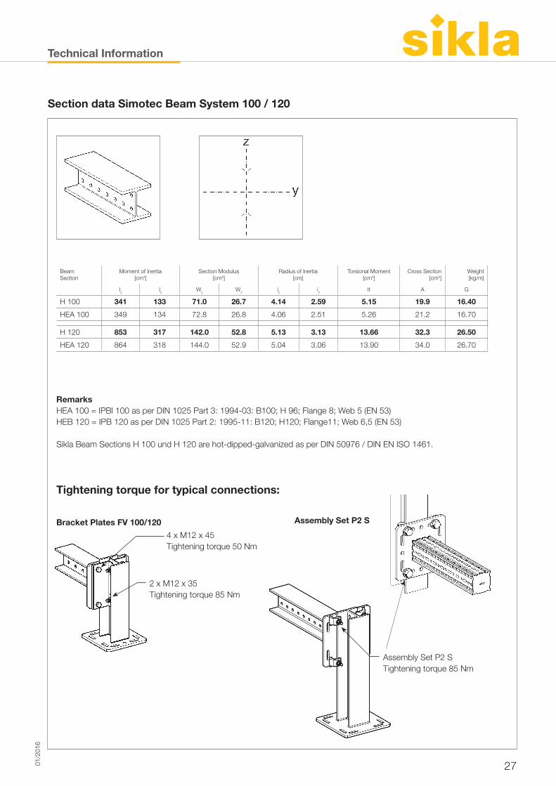
Section data Simotec Beam System 100 / 120
Beam Section
Moment of Inertia[cm4]
Section Modulus[cm3]
Radius of Inertia[cm]
Torsional Moment[cm4]
Cross Section[cm2]
Weight[kg/m]
Iy Iz Wy Wz iy iz lt A G
H 100 341 133 71.0 26.7 4.14 2.59 5.15 19.9 16.40
HEA 100 349 134 72.8 26.8 4.06 2.51 5.26 21.2 16.70
H 120 853 317 142.0 52.8 5.13 3.13 13.66 32.3 26.50
HEA 120 864 318 144.0 52.9 5.04 3.06 13.90 34.0 26.70
RemarksHEA 100 = IPBl 100 as per DIN 1025 Part 3: 1994-03: B100; H 96; Flange 8; Web 5 (EN 53)HEB 120 = IPB 120 as per DIN 1025 Part 2: 1995-11: B120; H120; Flange11; Web 6,5 (EN 53)
Sikla Beam Sections H 100 und H 120 are hot-dipped-galvanized as per DIN 50976 / DIN EN ISO 1461.
Tightening torque for typical connections:
4 x M12 x 45 Tightening torque 50 Nm
Bracket Plates FV 100/120
2 x M12 x 35 Tightening torque 85 Nm
Assembly Set P2 S Tightening torque 85 Nm
Assembly Set P2 S
Technical Information
28 01/2
016
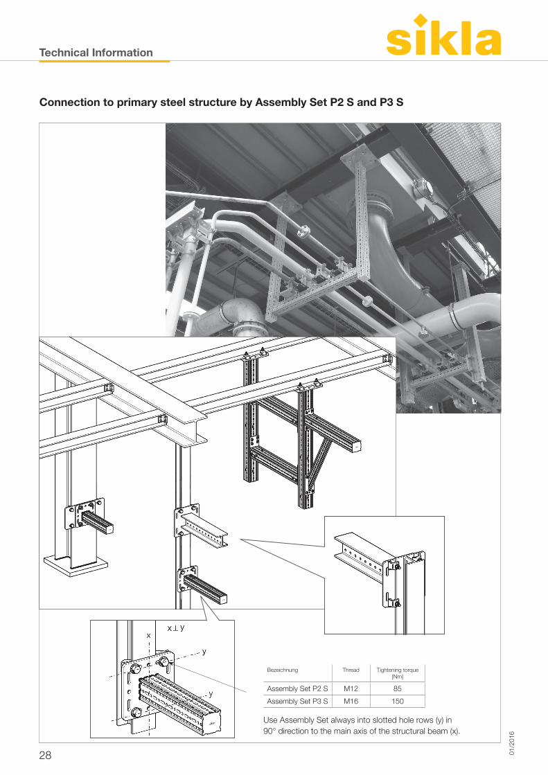
Connection to primary steel structure by Assembly Set P2 S and P3 S
Bezeichnung Thread Tightening torque[Nm]
Assembly Set P2 S M12 85
Assembly Set P3 S M16 150
Use Assembly Set always into slotted hole rows (y) in 90° direction to the main axis of the structural beam (x).