fortwo cdi (diesel), 2004 to 2006 Installation Guide
28
Welte Engineering . Chappelihof 18 . CH-8863 Buttikon . Switzerland Web: www.welte-engineering.ch . Information: [email protected] X-Gauge, Installation Guide, Version 1.77, © Copyright 2005-2014 Welte Engineering. All rights reserved. 1/28 X X - - G G a a u u g g e e For the smart ® fortwo (gasoline/petrol), 2001 to 2006 For the smart ® fortwo cdi (diesel), 2004 to 2006 Installation Guide
Transcript of fortwo cdi (diesel), 2004 to 2006 Installation Guide

Welte Engineering . Chappelihof 18
. CH-8863 Buttikon
. Switzerland
Web: www.welte-engineering.ch .
Information: [email protected]
X-Gauge, Installation Guide, Version 1.77, © Copyright 2005-2014 Welte Engineering. All rights reserved. 1/28
XX--GGaauuggee
For the smart® fortwo (gasoline/petrol), 2001 to 2006 For the smart® fortwo cdi (diesel), 2004 to 2006
Installation Guide
Welte Engineering . Chappelihof 18
. CH-8863 Buttikon
. Switzerland
Web: www.welte-engineering.ch .
Information: [email protected]
X-Gauge, Installation Guide, Version 1.77, © Copyright 2005-2014 Welte Engineering. All rights reserved. 2/28
Table of contents 1 Disclaimer........................................................................................................................... 3
2 Introduction......................................................................................................................... 3
3 Kit Contents ........................................................................................................................ 4
4 Required Tools.................................................................................................................... 5
5 Removing the Cockpit Clock from the Car ........................................................................ 6
6 Disassembling the Cockpit Clock....................................................................................... 7
7 Assembling the X-Gauge................................................................................................ 11
8 Installing the X-Gauge in the Car................................................................................... 17
9 Appendices ....................................................................................................................... 25
9.1 Removing the X-Gauge from the Car............................................................................. 25
9.2 Wire Connections ............................................................................................................. 28
Welte Engineering . Chappelihof 18
. CH-8863 Buttikon
. Switzerland
Web: www.welte-engineering.ch .
Information: [email protected]
X-Gauge, Installation Guide, Version 1.77, © Copyright 2005-2014 Welte Engineering. All rights reserved. 3/28
1 Disclaimer
The information contained in this document is subject to change and does not represent a com-
mitment on the part of the copyright holder. While the information contained herein is assumed to
be accurate, Welte Engineering assumes no responsibility for any errors or omissions. In no event
shall Welte Engineering be liable for special, direct, indirect, or consequential damage, losses,
costs, charges, claims, demands, or expenses of any nature or kind.
2 Introduction
Note that the X-Gauge will only work in the following cars:
- smart® fortwo, 2001 to 2006 with gasoline/petrol engine.
- smart® fortwo cdi, 2004 to 2006 with diesel engine.
- smart® roadster, all models.
These model limitations are due to the fact that the diagnostic interface in earlier models does not
deliver the generic engine parameters that the X-Gauge requests from the ECU, while models
after 2006 have a CAN based diagnostic interface implemented that the X-Gauge is not yet
compatible with.
This document is a step-by-step guide on how to change an original smart®
cockpit clock into an
X-Gauge. Before grabbing your tools and diving right into it, please familiarize yourself with all
installation procedures by reading this guide from front to back cover. If you do not feel comfort-
able with any of the installation steps, please find someone else who is qualified to do the job for
you. Be aware that the X-Gauge module is a delicate electronic device that must be handled
with proper care. The warranty will not cover any damage caused by incorrect installation or mis-
handling. Text and pictures in this document assume a left hand driven smart®, so you will have
to do some mirroring if your car is right hand driven.
Changing a cockpit clock into an X-Gauge is done in 4 distinct phases:
1) Removing the cockpit clock from the car.
2) Disassembling the cockpit clock.
3) Assembling the X-Gauge.
4) Installing the X-Gauge in the car.
Make sure that you’ll keep all remaining parts of the cockpit clock in a safe place so that you will
be able to change the X-Gauge back into the cockpit clock at a later time.
If it makes you feel more at ease you may disconnect the negative battery cable of your car during
the removal and installation phases. Be aware, though, that your car’s radio may request the entry
of a security code after its battery supply was interrupted, so you better have this code ready if
you decide to disconnect the battery.
Welte Engineering . Chappelihof 18
. CH-8863 Buttikon
. Switzerland
Web: www.welte-engineering.ch .
Information: [email protected]
X-Gauge, Installation Guide, Version 1.77, © Copyright 2005-2014 Welte Engineering. All rights reserved. 4/28
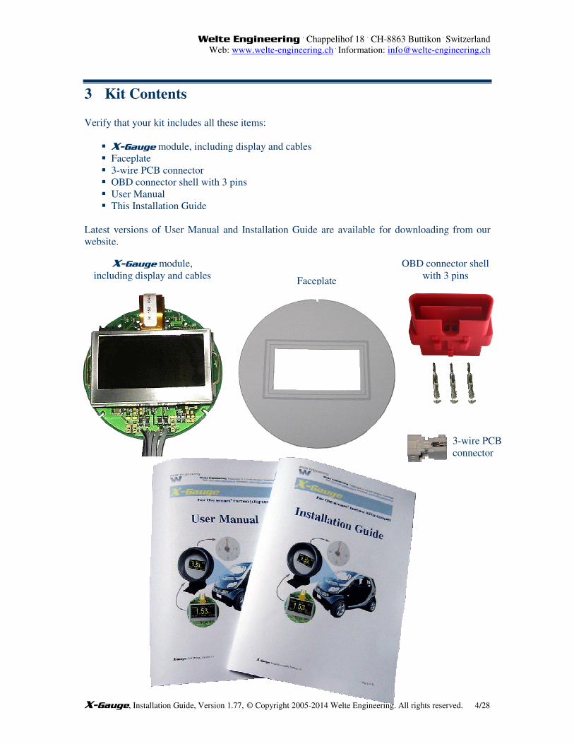
3 Kit Contents
Verify that your kit includes all these items:
� X-Gauge module, including display and cables
� Faceplate
� 3-wire PCB connector
� OBD connector shell with 3 pins
� User Manual
� This Installation Guide
Latest versions of User Manual and Installation Guide are available for downloading from our
website.
OBD connector shell
with 3 pins Faceplate
X-Gauge module,
including display and cables
3-wire PCB
connector

Welte Engineering . Chappelihof 18
. CH-8863 Buttikon
. Switzerland
Web: www.welte-engineering.ch .
Information: [email protected]
X-Gauge, Installation Guide, Version 1.77, © Copyright 2005-2014 Welte Engineering. All rights reserved. 5/28
4 Required Tools Examples of required tools are shown below. Instead of a mini clamp which is used for pressing
the 3-wire PCB connector together, you might also use a small vise. The side cutter is intended
for separating the cable of the original cockpit clock from the clock module but you might also
use a pair of scissor or a soldering iron instead.
Flat screwdriver approx. 1/4˝
Flat screwdriver approx. 1/10”
Torx screwdriver T10
Mini clamp or
small vise
Side cutter or scissors
Pliers
Welte Engineering . Chappelihof 18
. CH-8863 Buttikon
. Switzerland
Web: www.welte-engineering.ch .
Information: [email protected]
X-Gauge, Installation Guide, Version 1.77, © Copyright 2005-2014 Welte Engineering. All rights reserved. 6/28
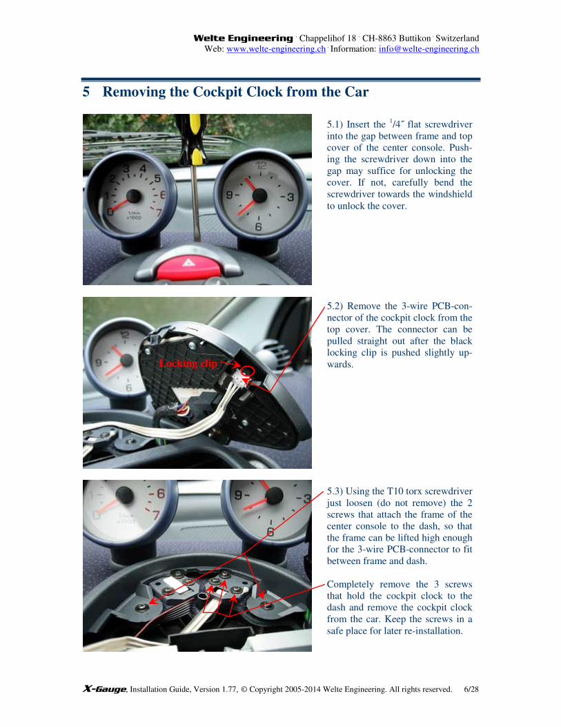
5 Removing the Cockpit Clock from the Car
5.1) Insert the 1/4˝ flat screwdriver
into the gap between frame and top
cover of the center console. Push-
ing the screwdriver down into the
gap may suffice for unlocking the
cover. If not, carefully bend the
screwdriver towards the windshield
to unlock the cover.
5.2) Remove the 3-wire PCB-con-
nector of the cockpit clock from the
top cover. The connector can be
pulled straight out after the black
locking clip is pushed slightly up-
wards.
5.3) Using the T10 torx screwdriver
just loosen (do not remove) the 2
screws that attach the frame of the
center console to the dash, so that
the frame can be lifted high enough
for the 3-wire PCB-connector to fit
between frame and dash.
Completely remove the 3 screws
that hold the cockpit clock to the
dash and remove the cockpit clock
from the car. Keep the screws in a
safe place for later re-installation.
Locking clip
Welte Engineering . Chappelihof 18
. CH-8863 Buttikon
. Switzerland
Web: www.welte-engineering.ch .
Information: [email protected]
X-Gauge, Installation Guide, Version 1.77, © Copyright 2005-2014 Welte Engineering. All rights reserved. 7/28
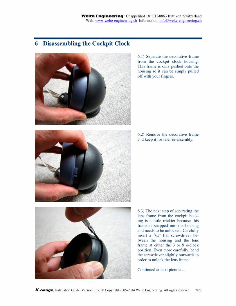
6 Disassembling the Cockpit Clock
6.1) Separate the decorative frame
from the cockpit clock housing.
This frame is only pushed onto the
housing so it can be simply pulled
off with your fingers.
6.2) Remove the decorative frame
and keep it for later re-assembly.
6.3) The next step of separating the
lens frame from the cockpit hous-
ing is a little trickier because this
frame is snapped into the housing
and needs to be unlocked. Carefully
insert a 1/10” flat screwdriver be-
tween the housing and the lens
frame at either the 3 or 9 o-clock
position. Even more carefully, bend
the screwdriver slightly outwards in
order to unlock the lens frame.
Continued at next picture …
Welte Engineering . Chappelihof 18
. CH-8863 Buttikon
. Switzerland
Web: www.welte-engineering.ch .
Information: [email protected]
X-Gauge, Installation Guide, Version 1.77, © Copyright 2005-2014 Welte Engineering. All rights reserved. 8/28
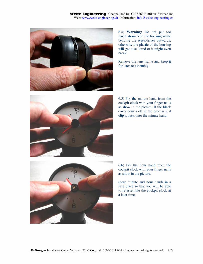
6.4) Warning: Do not put too
much strain onto the housing while
bending the screwdriver outwards,
otherwise the plastic of the housing
will get discolored or it might even
break!
Remove the lens frame and keep it
for later re-assembly.
6.5) Pry the minute hand from the
cockpit clock with your finger nails
as show in the picture. If the black
cover comes off in the process just
clip it back onto the minute hand.
6.6) Pry the hour hand from the
cockpit clock with your finger nails
as show in the picture.
Store minute and hour hands in a
safe place so that you will be able
to re-assemble the cockpit clock at
a later time.
Welte Engineering . Chappelihof 18
. CH-8863 Buttikon
. Switzerland
Web: www.welte-engineering.ch .
Information: [email protected]
X-Gauge, Installation Guide, Version 1.77, © Copyright 2005-2014 Welte Engineering. All rights reserved. 9/28
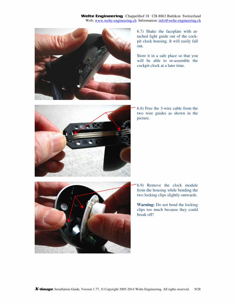
6.7) Shake the faceplate with at-
tached light guide out of the cock-
pit clock housing. It will easily fall
out.
Store it in a safe place so that you
will be able to re-assemble the
cockpit clock at a later time.
6.8) Free the 3-wire cable from the
two wire guides as shown in the
picture.
6.9) Remove the clock module
from the housing while bending the
two locking clips slightly outwards.
Warning: Do not bend the locking
clips too much because they could
break off!
Welte Engineering . Chappelihof 18
. CH-8863 Buttikon
. Switzerland
Web: www.welte-engineering.ch .
Information: [email protected]
X-Gauge, Installation Guide, Version 1.77, © Copyright 2005-2014 Welte Engineering. All rights reserved. 10/28
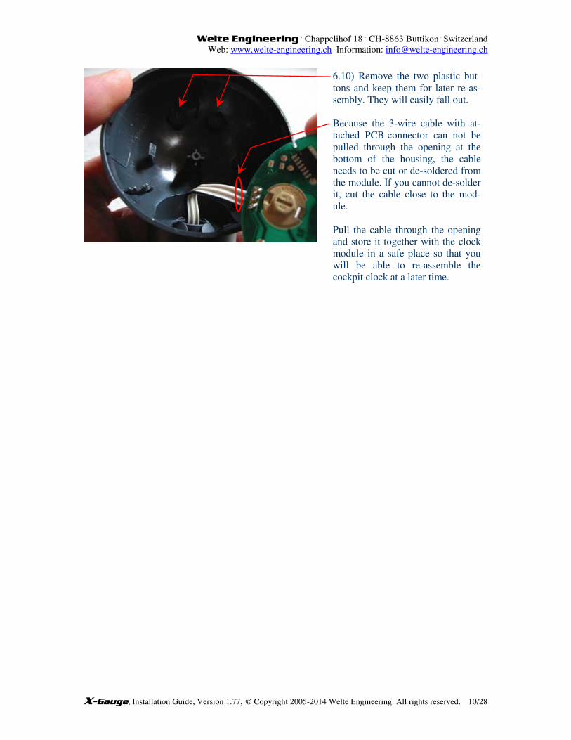
6.10) Remove the two plastic but-
tons and keep them for later re-as-
sembly. They will easily fall out.
Because the 3-wire cable with at-
tached PCB-connector can not be
pulled through the opening at the
bottom of the housing, the cable
needs to be cut or de-soldered from
the module. If you cannot de-solder
it, cut the cable close to the mod-
ule.
Pull the cable through the opening
and store it together with the clock
module in a safe place so that you
will be able to re-assemble the
cockpit clock at a later time.
Welte Engineering . Chappelihof 18
. CH-8863 Buttikon
. Switzerland
Web: www.welte-engineering.ch .
Information: [email protected]
X-Gauge, Installation Guide, Version 1.77, © Copyright 2005-2014 Welte Engineering. All rights reserved. 11/28
7 Assembling the X-Gauge
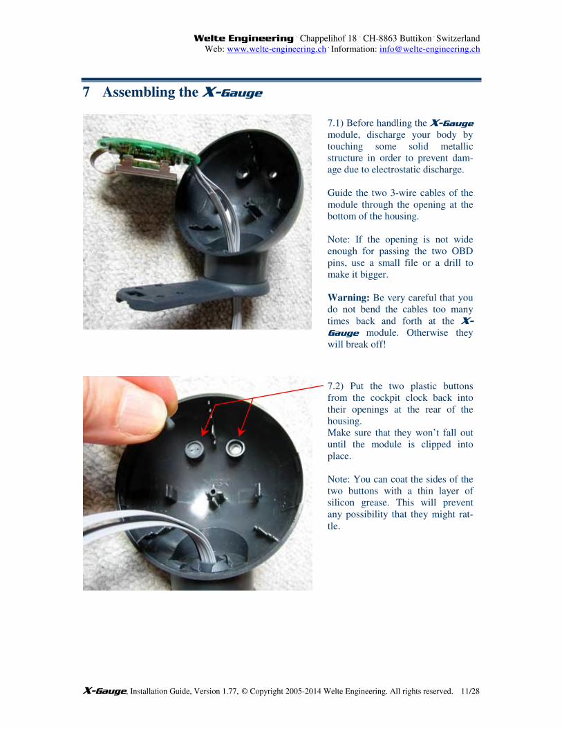
7.1) Before handling the X-Gauge
module, discharge your body by
touching some solid metallic
structure in order to prevent dam-
age due to electrostatic discharge.
Guide the two 3-wire cables of the
module through the opening at the
bottom of the housing.
Note: If the opening is not wide
enough for passing the two OBD
pins, use a small file or a drill to
make it bigger.
Warning: Be very careful that you
do not bend the cables too many
times back and forth at the X-Gauge module. Otherwise they
will break off!
7.2) Put the two plastic buttons
from the cockpit clock back into
their openings at the rear of the
housing.
Make sure that they won’t fall out
until the module is clipped into
place.
Note: You can coat the sides of the
two buttons with a thin layer of
silicon grease. This will prevent
any possibility that they might rat-
tle.
Welte Engineering . Chappelihof 18
. CH-8863 Buttikon
. Switzerland
Web: www.welte-engineering.ch .
Information: [email protected]
X-Gauge, Installation Guide, Version 1.77, © Copyright 2005-2014 Welte Engineering. All rights reserved. 12/28
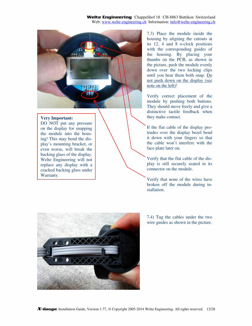
7.3) Place the module inside the
housing by aligning the cutouts at
its 12, 4 and 8 o-clock positions
with the corresponding guides of
the housing. By placing your
thumbs on the PCB, as shown in
the picture, push the module evenly
down over the two locking clips
until you hear them both snap. Do
not push down on the display (see
note on the left)!
Verify correct placement of the
module by pushing both buttons.
They should move freely and give a
distinctive tactile feedback when
they make contact.
If the flat cable of the display pro-
trudes over the display bezel bend
it down with your fingers so that
the cable won’t interfere with the
face plate later on.
Verify that the flat cable of the dis-
play is still securely seated in its
connector on the module.
Verify that none of the wires have
broken off the module during in-
stallation.
7.4) Tug the cables under the two
wire guides as shown in the picture.
Very Important:
DO NOT put any pressure
on the display for snapping
the module into the hous-
ing! This may bend the dis-
play’s mounting bracket, or
even worse, will break the
backing glass of the display.
Welte Engineering will not
replace any display with a
cracked backing glass under
Warranty.
Welte Engineering . Chappelihof 18
. CH-8863 Buttikon
. Switzerland
Web: www.welte-engineering.ch .
Information: [email protected]
X-Gauge, Installation Guide, Version 1.77, © Copyright 2005-2014 Welte Engineering. All rights reserved. 13/28
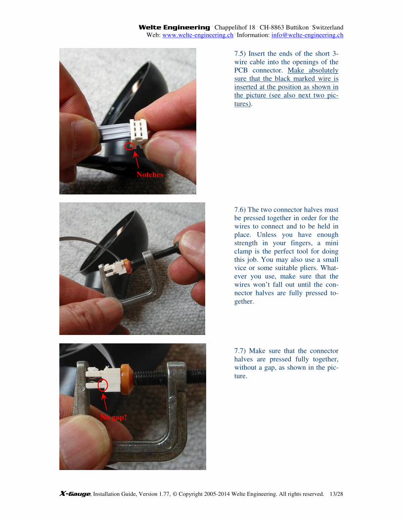
7.5) Insert the ends of the short 3-
wire cable into the openings of the
PCB connector. Make absolutely
sure that the black marked wire is
inserted at the position as shown in
the picture (see also next two pic-
tures).
Notches
7.6) The two connector halves must
be pressed together in order for the
wires to connect and to be held in
place. Unless you have enough
strength in your fingers, a mini
clamp is the perfect tool for doing
this job. You may also use a small
vice or some suitable pliers. What-
ever you use, make sure that the
wires won’t fall out until the con-
nector halves are fully pressed to-
gether.
7.7) Make sure that the connector
halves are pressed fully together,
without a gap, as shown in the pic-
ture.
No gap!
Welte Engineering . Chappelihof 18
. CH-8863 Buttikon
. Switzerland
Web: www.welte-engineering.ch .
Information: [email protected]
X-Gauge, Installation Guide, Version 1.77, © Copyright 2005-2014 Welte Engineering. All rights reserved. 14/28
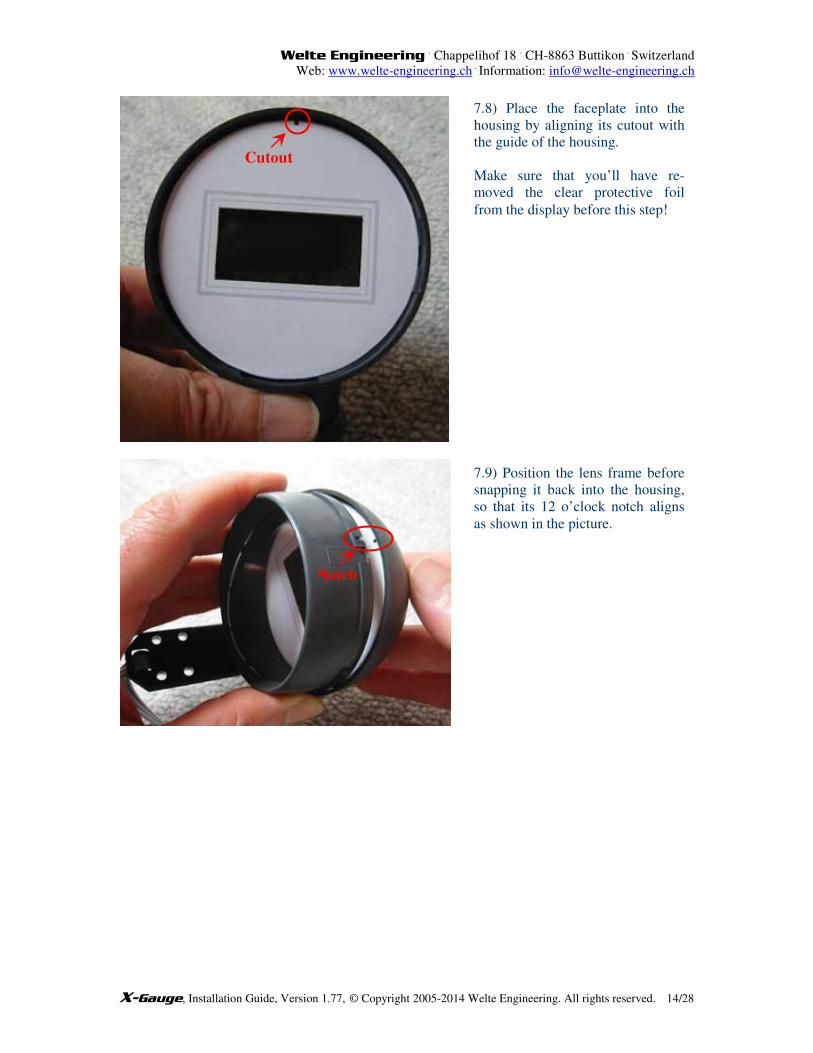
Cutout
7.8) Place the faceplate into the
housing by aligning its cutout with
the guide of the housing.
Make sure that you’ll have re-
moved the clear protective foil
from the display before this step!
7.9) Position the lens frame before
snapping it back into the housing,
so that its 12 o’clock notch aligns
as shown in the picture.
Notch
Welte Engineering . Chappelihof 18
. CH-8863 Buttikon
. Switzerland
Web: www.welte-engineering.ch .
Information: [email protected]
X-Gauge, Installation Guide, Version 1.77, © Copyright 2005-2014 Welte Engineering. All rights reserved. 15/28
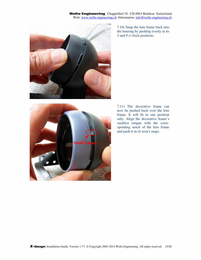
7.10) Snap the lens frame back into
the housing by pushing evenly at its
3 and 9 o’clock positions.
7.11) The decorative frame can
now be pushed back over the lens
frame. It will fit in one position
only. Align the decorative frame’s
smallest tongue with the corre-
sponding notch of the lens frame
and push it in (it won’t snap).
Small Tongue
Welte Engineering . Chappelihof 18
. CH-8863 Buttikon
. Switzerland
Web: www.welte-engineering.ch .
Information: [email protected]
X-Gauge, Installation Guide, Version 1.77, © Copyright 2005-2014 Welte Engineering. All rights reserved. 16/28
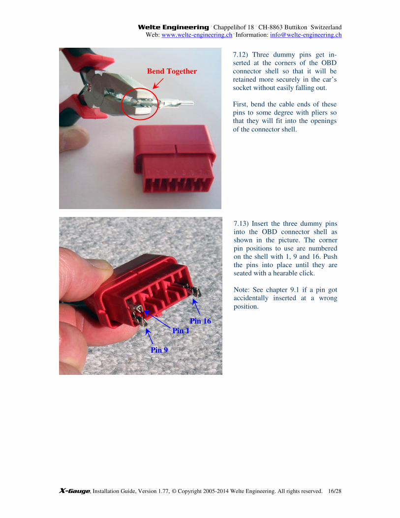
7.12) Three dummy pins get in-
serted at the corners of the OBD
connector shell so that it will be
retained more securely in the car’s
socket without easily falling out.
First, bend the cable ends of these
pins to some degree with pliers so
that they will fit into the openings
of the connector shell.
7.13) Insert the three dummy pins
into the OBD connector shell as
shown in the picture. The corner
pin positions to use are numbered
on the shell with 1, 9 and 16. Push
the pins into place until they are
seated with a hearable click.
Note: See chapter 9.1 if a pin got
accidentally inserted at a wrong
position.
Pin 16
Pin 9
Pin 1
Bend Together
Welte Engineering . Chappelihof 18
. CH-8863 Buttikon
. Switzerland
Web: www.welte-engineering.ch .
Information: [email protected]
X-Gauge, Installation Guide, Version 1.77, © Copyright 2005-2014 Welte Engineering. All rights reserved. 17/28
8 Installing the X-Gauge in the Car
- For 1st generation smart
® cars (2002 and before) continue with step 8.3.
- For 2nd
generation smart®
cars (2003 and up) continue with step 8.11.
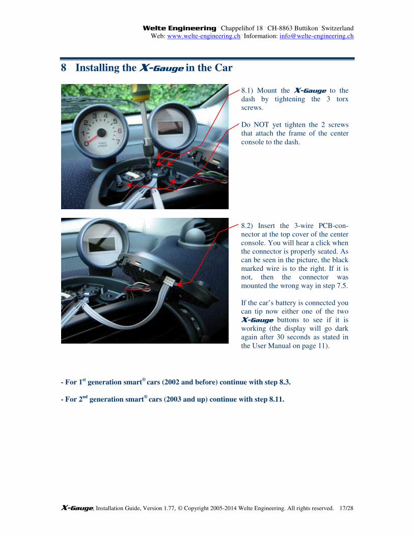
8.1) Mount the X-Gauge to the
dash by tightening the 3 torx
screws.
Do NOT yet tighten the 2 screws
that attach the frame of the center
console to the dash.
8.2) Insert the 3-wire PCB-con-
nector at the top cover of the center
console. You will hear a click when
the connector is properly seated. As
can be seen in the picture, the black
marked wire is to the right. If it is
not, then the connector was
mounted the wrong way in step 7.5.
If the car’s battery is connected you
can tip now either one of the two
X-Gauge buttons to see if it is
working (the display will go dark
again after 30 seconds as stated in
the User Manual on page 11).
Welte Engineering . Chappelihof 18
. CH-8863 Buttikon
. Switzerland
Web: www.welte-engineering.ch .
Information: [email protected]
X-Gauge, Installation Guide, Version 1.77, © Copyright 2005-2014 Welte Engineering. All rights reserved. 18/28
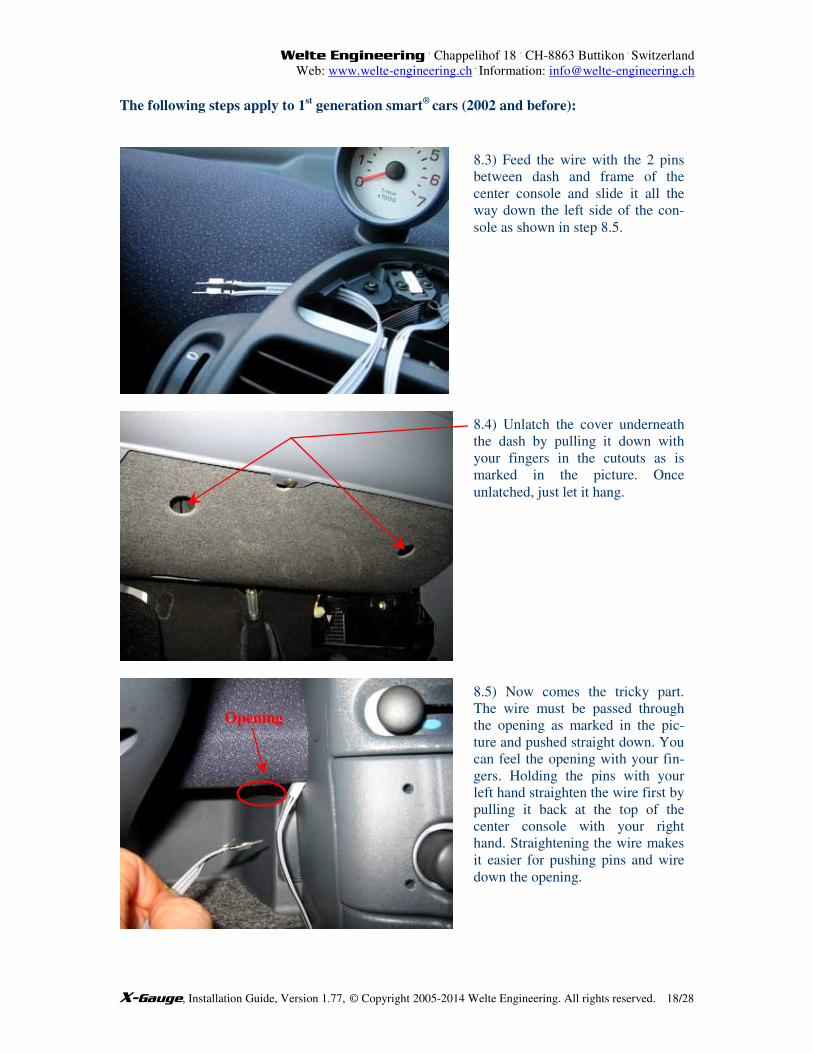
The following steps apply to 1st generation smart
® cars (2002 and before):
8.3) Feed the wire with the 2 pins
between dash and frame of the
center console and slide it all the
way down the left side of the con-
sole as shown in step 8.5.
8.5) Now comes the tricky part.
The wire must be passed through
the opening as marked in the pic-
ture and pushed straight down. You
can feel the opening with your fin-
gers. Holding the pins with your
left hand straighten the wire first by
pulling it back at the top of the
center console with your right
hand. Straightening the wire makes
it easier for pushing pins and wire
down the opening.
Opening
8.4) Unlatch the cover underneath
the dash by pulling it down with
your fingers in the cutouts as is
marked in the picture. Once
unlatched, just let it hang.
Welte Engineering . Chappelihof 18
. CH-8863 Buttikon
. Switzerland
Web: www.welte-engineering.ch .
Information: [email protected]
X-Gauge, Installation Guide, Version 1.77, © Copyright 2005-2014 Welte Engineering. All rights reserved. 19/28
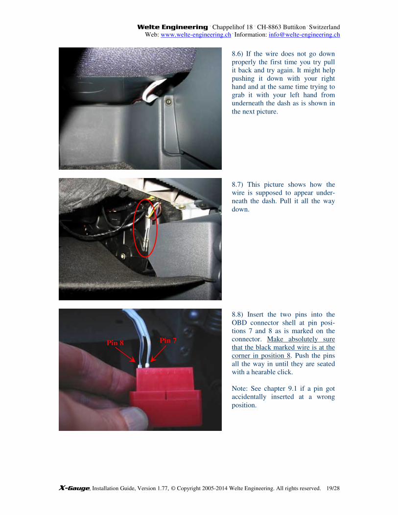
8.6) If the wire does not go down
properly the first time you try pull
it back and try again. It might help
pushing it down with your right
hand and at the same time trying to
grab it with your left hand from
underneath the dash as is shown in
the next picture.
8.7) This picture shows how the
wire is supposed to appear under-
neath the dash. Pull it all the way
down.
8.8) Insert the two pins into the
OBD connector shell at pin posi-
tions 7 and 8 as is marked on the
connector. Make absolutely sure
that the black marked wire is at the
corner in position 8. Push the pins
all the way in until they are seated
with a hearable click.
Note: See chapter 9.1 if a pin got
accidentally inserted at a wrong
position.
Pin 8 Pin 7
Welte Engineering . Chappelihof 18
. CH-8863 Buttikon
. Switzerland
Web: www.welte-engineering.ch .
Information: [email protected]
X-Gauge, Installation Guide, Version 1.77, © Copyright 2005-2014 Welte Engineering. All rights reserved. 20/28
- Continue with step 8.18.
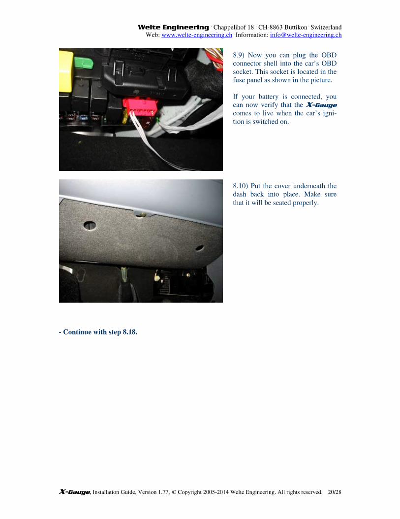
8.9) Now you can plug the OBD
connector shell into the car’s OBD
socket. This socket is located in the
fuse panel as shown in the picture.
If your battery is connected, you
can now verify that the X-Gauge
comes to live when the car’s igni-
tion is switched on.
8.10) Put the cover underneath the
dash back into place. Make sure
that it will be seated properly.
Welte Engineering . Chappelihof 18
. CH-8863 Buttikon
. Switzerland
Web: www.welte-engineering.ch .
Information: [email protected]
X-Gauge, Installation Guide, Version 1.77, © Copyright 2005-2014 Welte Engineering. All rights reserved. 21/28
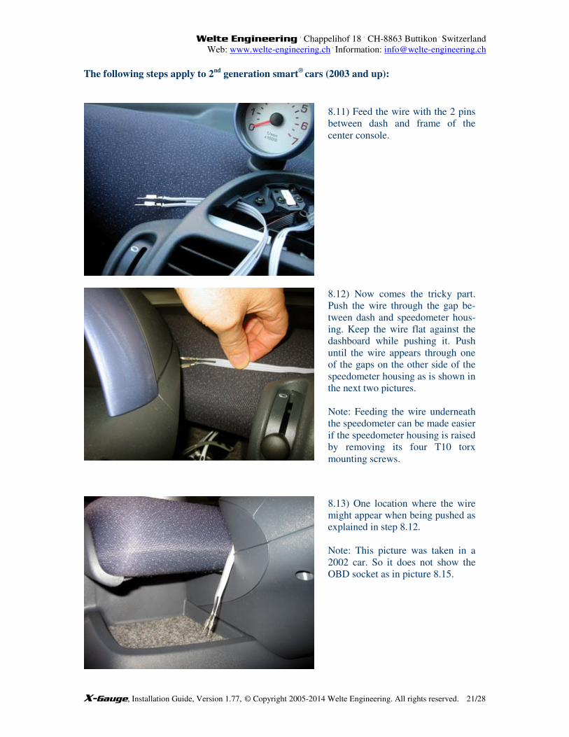
The following steps apply to 2nd
generation smart®
cars (2003 and up):
8.11) Feed the wire with the 2 pins
between dash and frame of the
center console.
8.12) Now comes the tricky part.
Push the wire through the gap be-
tween dash and speedometer hous-
ing. Keep the wire flat against the
dashboard while pushing it. Push
until the wire appears through one
of the gaps on the other side of the
speedometer housing as is shown in
the next two pictures.
Note: Feeding the wire underneath
the speedometer can be made easier
if the speedometer housing is raised
by removing its four T10 torx
mounting screws.
8.13) One location where the wire
might appear when being pushed as
explained in step 8.12.
Note: This picture was taken in a
2002 car. So it does not show the
OBD socket as in picture 8.15.
Welte Engineering . Chappelihof 18
. CH-8863 Buttikon
. Switzerland
Web: www.welte-engineering.ch .
Information: [email protected]
X-Gauge, Installation Guide, Version 1.77, © Copyright 2005-2014 Welte Engineering. All rights reserved. 22/28
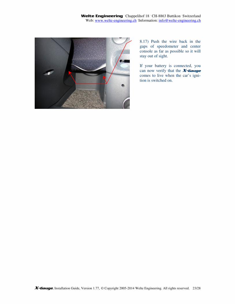
8.15) This picture shows the actual
location of the OBD socket in a
2003 or later car. The socket is
protected by a cover that must be
flipped down.
Note: The cover might rattle when
it stays open while the OBD con-
nector of the X-Gauge is plugged
in. You can stop this noise by either
pulling the cover off or by lining
the bottom of the storage area with
foam or carpet.
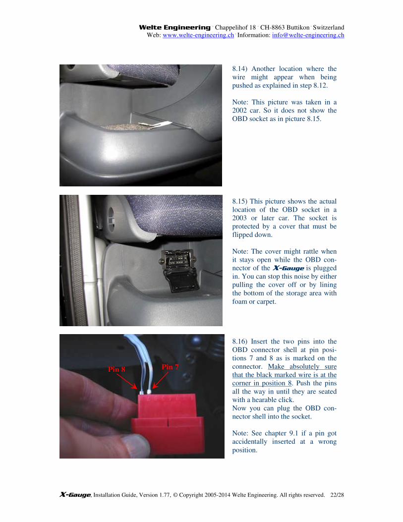
8.14) Another location where the
wire might appear when being
pushed as explained in step 8.12.
Note: This picture was taken in a
2002 car. So it does not show the
OBD socket as in picture 8.15.
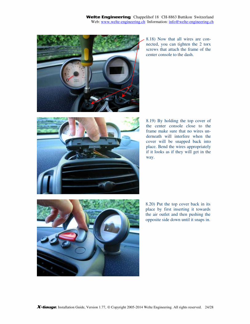
Pin 8 Pin 7
8.16) Insert the two pins into the
OBD connector shell at pin posi-
tions 7 and 8 as is marked on the
connector. Make absolutely sure
that the black marked wire is at the
corner in position 8. Push the pins
all the way in until they are seated
with a hearable click.
Now you can plug the OBD con-
nector shell into the socket.
Note: See chapter 9.1 if a pin got
accidentally inserted at a wrong
position.
Welte Engineering . Chappelihof 18
. CH-8863 Buttikon
. Switzerland
Web: www.welte-engineering.ch .
Information: [email protected]
X-Gauge, Installation Guide, Version 1.77, © Copyright 2005-2014 Welte Engineering. All rights reserved. 23/28
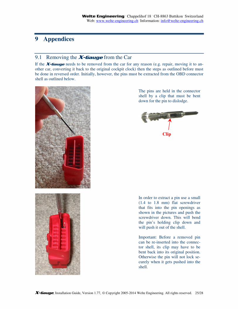
8.17) Push the wire back in the
gaps of speedometer and center
console as far as possible so it will
stay out of sight.
If your battery is connected, you
can now verify that the X-Gauge
comes to live when the car’s igni-
tion is switched on.
Welte Engineering . Chappelihof 18
. CH-8863 Buttikon
. Switzerland
Web: www.welte-engineering.ch .
Information: [email protected]
X-Gauge, Installation Guide, Version 1.77, © Copyright 2005-2014 Welte Engineering. All rights reserved. 24/28
8.18) Now that all wires are con-
nected, you can tighten the 2 torx
screws that attach the frame of the
center console to the dash.
8.19) By holding the top cover of
the center console close to the
frame make sure that no wires un-
derneath will interfere when the
cover will be snapped back into
place. Bend the wires appropriately
if it looks as if they will get in the
way.
8.20) Put the top cover back in its
place by first inserting it towards
the air outlet and then pushing the
opposite side down until it snaps in.
Welte Engineering . Chappelihof 18
. CH-8863 Buttikon
. Switzerland
Web: www.welte-engineering.ch .
Information: [email protected]
X-Gauge, Installation Guide, Version 1.77, © Copyright 2005-2014 Welte Engineering. All rights reserved. 25/28
9 Appendices
9.1 Removing the X-Gauge from the Car
If the X-Gauge needs to be removed from the car for any reason (e.g. repair, moving it to an-
other car, converting it back to the original cockpit clock) then the steps as outlined before must
be done in reversed order. Initially, however, the pins must be extracted from the OBD connector
shell as outlined below.
The pins are held in the connector
shell by a clip that must be bent
down for the pin to dislodge.
Clip
In order to extract a pin use a small
(1.4 to 1.8 mm) flat screwdriver
that fits into the pin openings as
shown in the pictures and push the
screwdriver down. This will bend
the pin’s holding clip down and
will push it out of the shell.
Important: Before a removed pin
can be re-inserted into the connec-
tor shell, its clip may have to be
bent back into its original position.
Otherwise the pin will not lock se-
curely when it gets pushed into the
shell.
Welte Engineering . Chappelihof 18
. CH-8863 Buttikon
. Switzerland
Web: www.welte-engineering.ch .
Information: [email protected]
X-Gauge, Installation Guide, Version 1.77, © Copyright 2005-2014 Welte Engineering. All rights reserved. 26/28
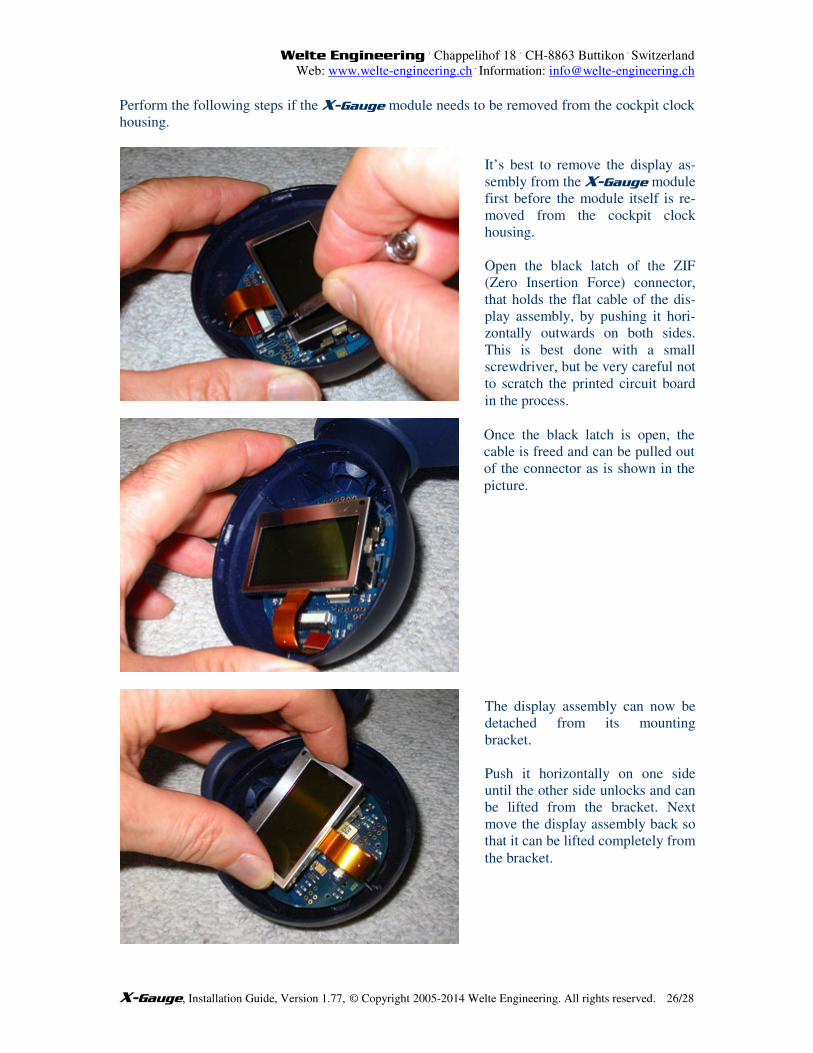
Perform the following steps if the X-Gauge module needs to be removed from the cockpit clock
housing.
It’s best to remove the display as-
sembly from the X-Gauge module
first before the module itself is re-
moved from the cockpit clock
housing.
Open the black latch of the ZIF
(Zero Insertion Force) connector,
that holds the flat cable of the dis-
play assembly, by pushing it hori-
zontally outwards on both sides.
This is best done with a small
screwdriver, but be very careful not
to scratch the printed circuit board
in the process.
Once the black latch is open, the
cable is freed and can be pulled out
of the connector as is shown in the
picture.
The display assembly can now be
detached from its mounting
bracket.
Push it horizontally on one side
until the other side unlocks and can
be lifted from the bracket. Next
move the display assembly back so
that it can be lifted completely from
the bracket.
Welte Engineering . Chappelihof 18
. CH-8863 Buttikon
. Switzerland
Web: www.welte-engineering.ch .
Information: [email protected]
X-Gauge, Installation Guide, Version 1.77, © Copyright 2005-2014 Welte Engineering. All rights reserved. 27/28
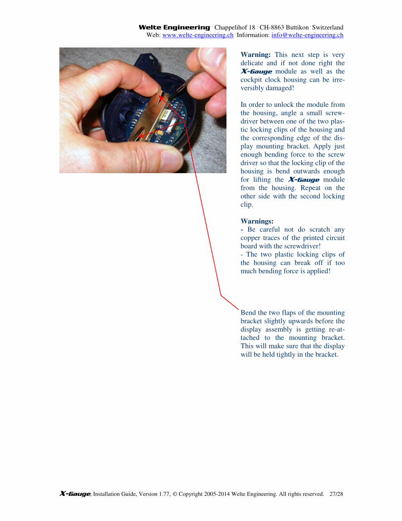
Warning: This next step is very
delicate and if not done right the
X-Gauge module as well as the
cockpit clock housing can be irre-
versibly damaged!
In order to unlock the module from
the housing, angle a small screw-
driver between one of the two plas-
tic locking clips of the housing and
the corresponding edge of the dis-
play mounting bracket. Apply just
enough bending force to the screw
driver so that the locking clip of the
housing is bend outwards enough
for lifting the X-Gauge module
from the housing. Repeat on the
other side with the second locking
clip.
Warnings: - Be careful not do scratch any
copper traces of the printed circuit
board with the screwdriver!
- The two plastic locking clips of
the housing can break off if too
much bending force is applied!
Bend the two flaps of the mounting
bracket slightly upwards before the
display assembly is getting re-at-
tached to the mounting bracket.
This will make sure that the display
will be held tightly in the bracket.
Welte Engineering . Chappelihof 18
. CH-8863 Buttikon
. Switzerland
Web: www.welte-engineering.ch .
Information: [email protected]
X-Gauge, Installation Guide, Version 1.77, © Copyright 2005-2014 Welte Engineering. All rights reserved. 28/28
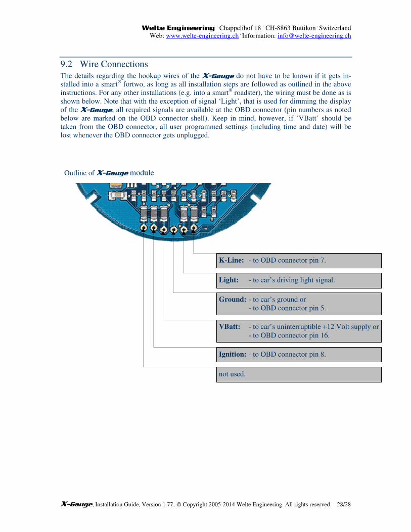
9.2 Wire Connections
The details regarding the hookup wires of the X-Gauge do not have to be known if it gets in-
stalled into a smart® fortwo, as long as all installation steps are followed as outlined in the above
instructions. For any other installations (e.g. into a smart® roadster), the wiring must be done as is
shown below. Note that with the exception of signal ‘Light’, that is used for dimming the display
of the X-Gauge, all required signals are available at the OBD connector (pin numbers as noted
below are marked on the OBD connector shell). Keep in mind, however, if ‘VBatt’ should be
taken from the OBD connector, all user programmed settings (including time and date) will be
lost whenever the OBD connector gets unplugged.
K-Line: - to OBD connector pin 7.
VBatt: - to car’s uninterruptible +12 Volt supply or
- to OBD connector pin 16.
Ground: - to car’s ground or
- to OBD connector pin 5.
Light: - to car’s driving light signal.
Ignition: - to OBD connector pin 8.
not used.
Outline of X-Gauge module