For soundcards and SDR receivers · 1 (c) Telecommunication and electronic components Audio...
10
1 Telecommunication and electronic components (c) Audio galvanic isolator For soundcards and SDR receivers 1. Principle A ground loop through receivers between antenna or USB connection and soundcard input is very common for soundcard based SDR receivers, where the soundcard are used to sample the I/Q channels. This type of ground loop problem can be solved by using suitable galvanic isolation between the receiver I/Q output and the soundcard input: The audio galvanic isolator is build by a couple of broadband audio transformers and have a symmetrical design. The input / output impedance is 600 Ohm (turn ratio = 1:1), therefore you can also invert the input and output connections.
Transcript of For soundcards and SDR receivers · 1 (c) Telecommunication and electronic components Audio...
1
Telecommunication and electronic components(c)
Audio galvanic isolator For soundcards and SDR
receivers1. Principle
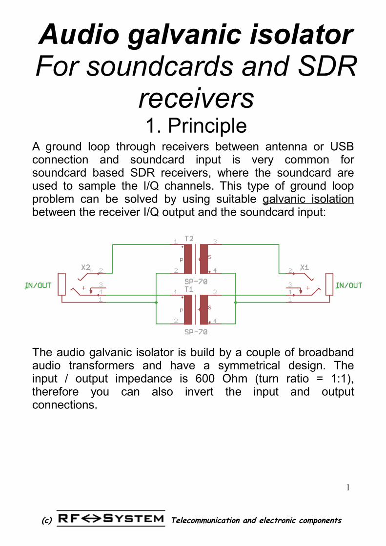
A ground loop through receivers between antenna or USB connection and soundcard input is very common for soundcard based SDR receivers, where the soundcard are used to sample the I/Q channels. This type of ground loop problem can be solved by using suitable galvanic isolation between the receiver I/Q output and the soundcard input:
The audio galvanic isolator is build by a couple of broadband audio transformers and have a symmetrical design. The input / output impedance is 600 Ohm (turn ratio = 1:1), therefore you can also invert the input and output connections.
2
Telecommunication and electronic components(c)
Audio galvanic isolator For soundcards and SDR
receivers2. Kit parts
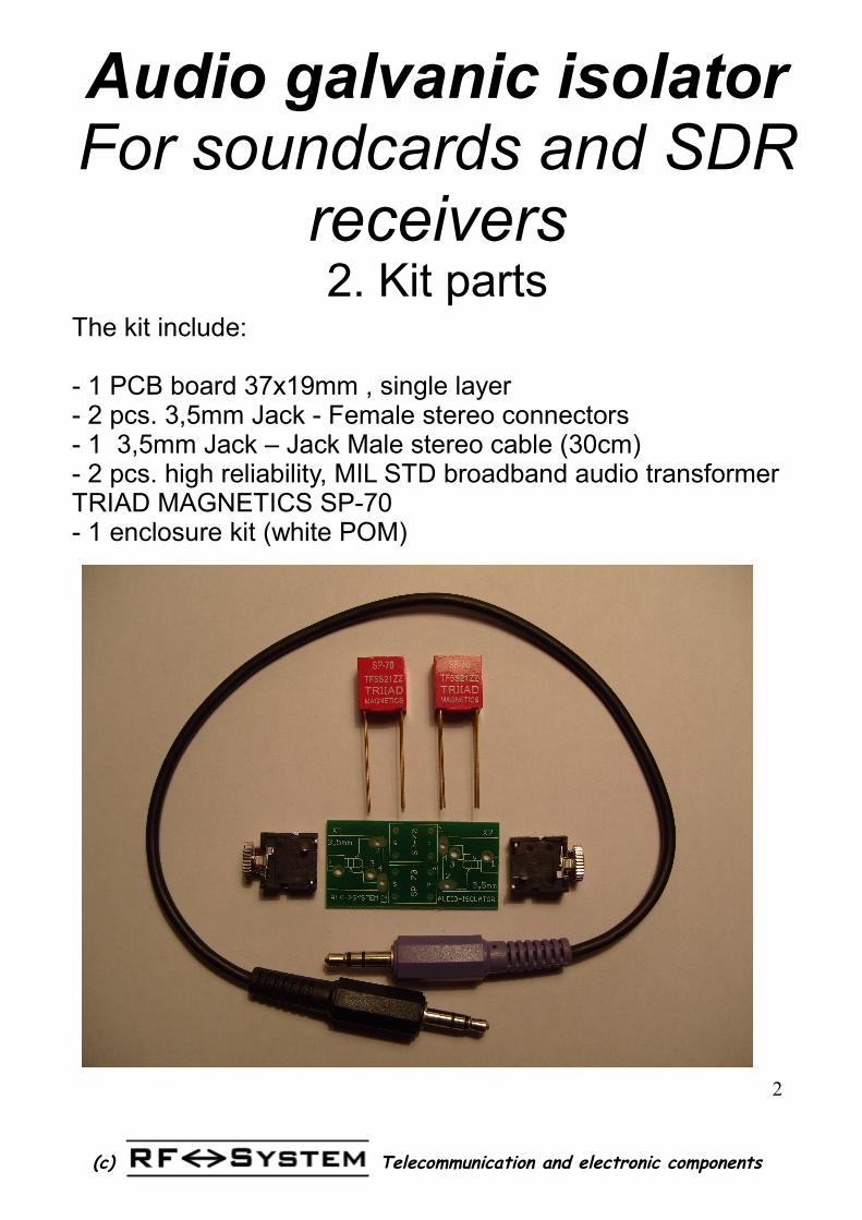
The kit include:
- 1 PCB board 37x19mm , single layer- 2 pcs. 3,5mm Jack - Female stereo connectors- 1 3,5mm Jack – Jack Male stereo cable (30cm)- 2 pcs. high reliability, MIL STD broadband audio transformer TRIAD MAGNETICS SP-70- 1 enclosure kit (white POM)
3
Telecommunication and electronic components(c)
Audio galvanic isolator For soundcards and SDR
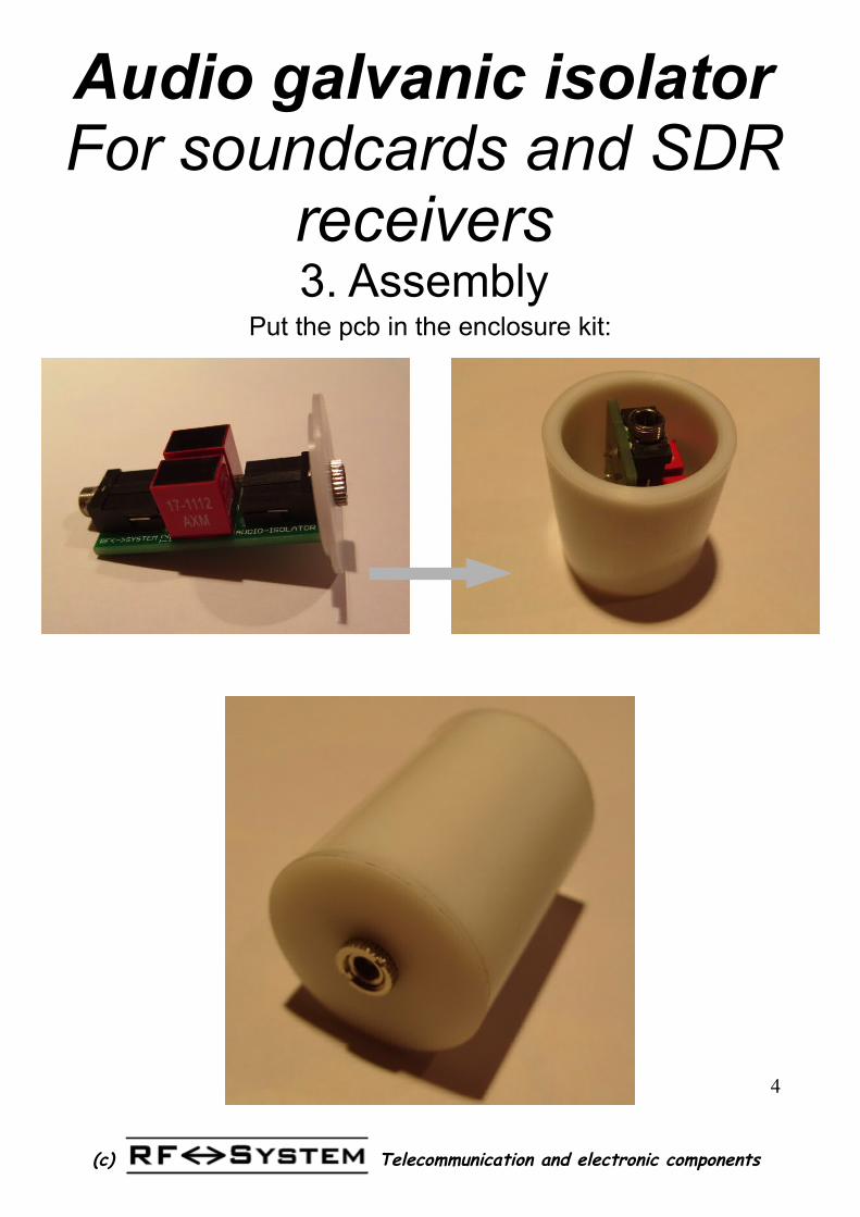
receivers3. Assembly
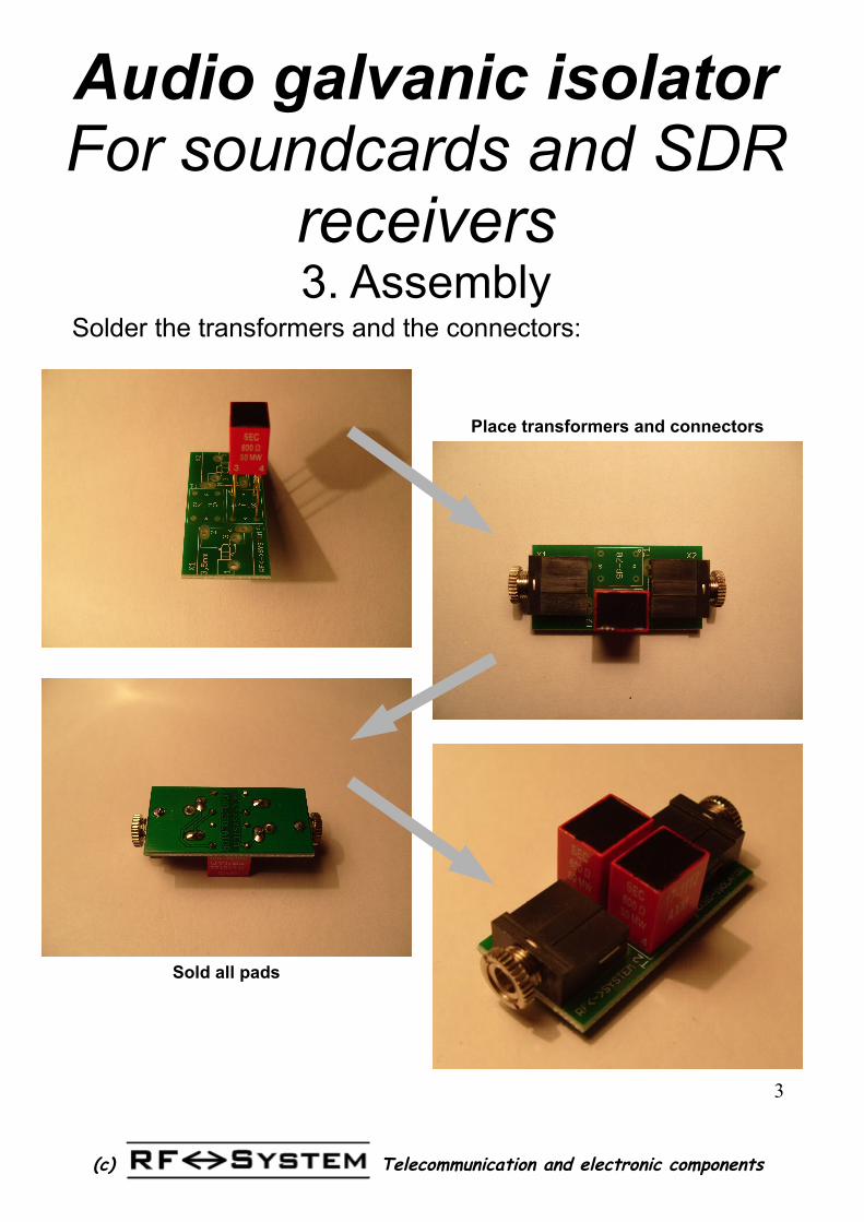
Solder the transformers and the connectors:
Place transformers and connectors
Sold all pads
4
Telecommunication and electronic components(c)
Audio galvanic isolator For soundcards and SDR
receivers3. Assembly
Put the pcb in the enclosure kit:
5
Telecommunication and electronic components(c)
Audio galvanic isolatorfor receivers
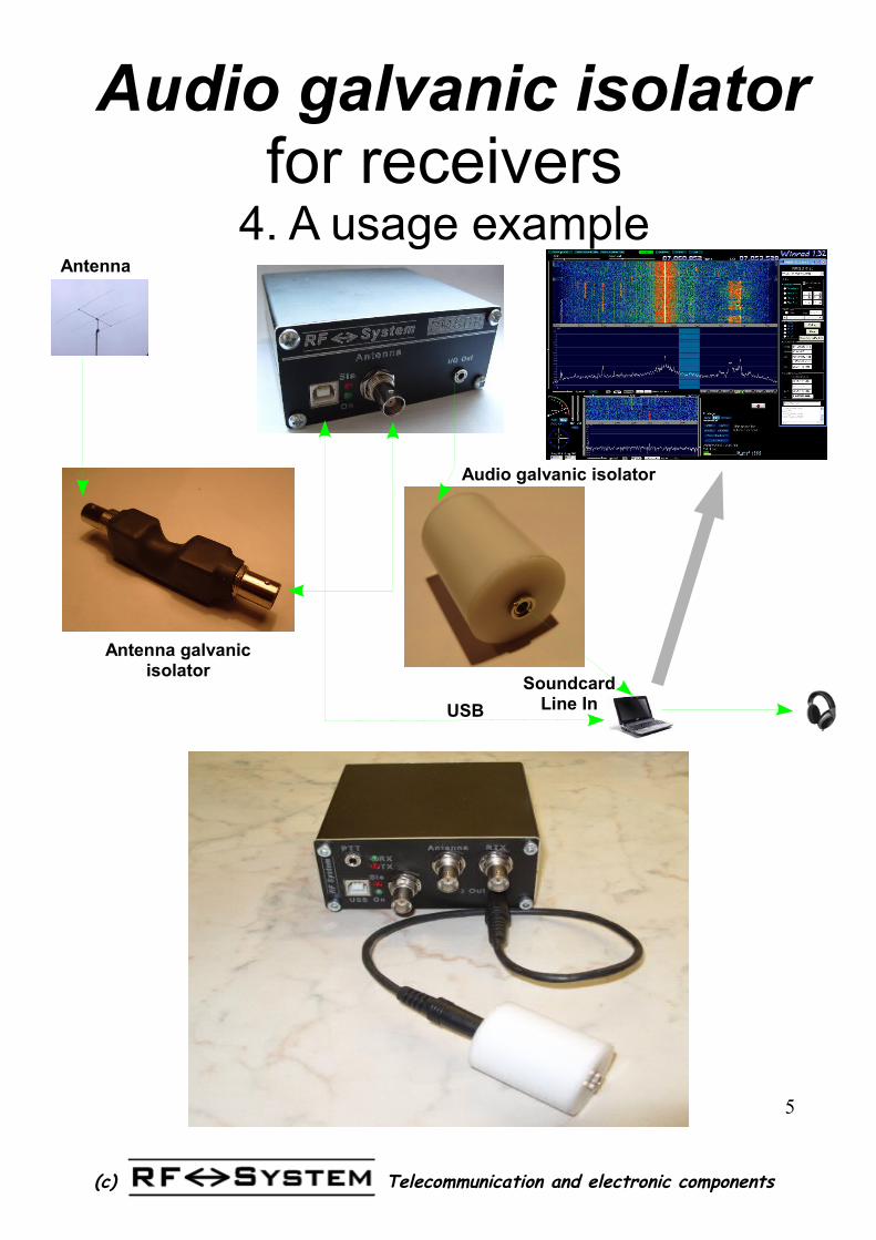
4. A usage example
SoundcardLine InUSB
Antenna
Antenna galvanic isolator
Audio galvanic isolator
6
Telecommunication and electronic components(c)
Audio galvanic isolatorfor receivers
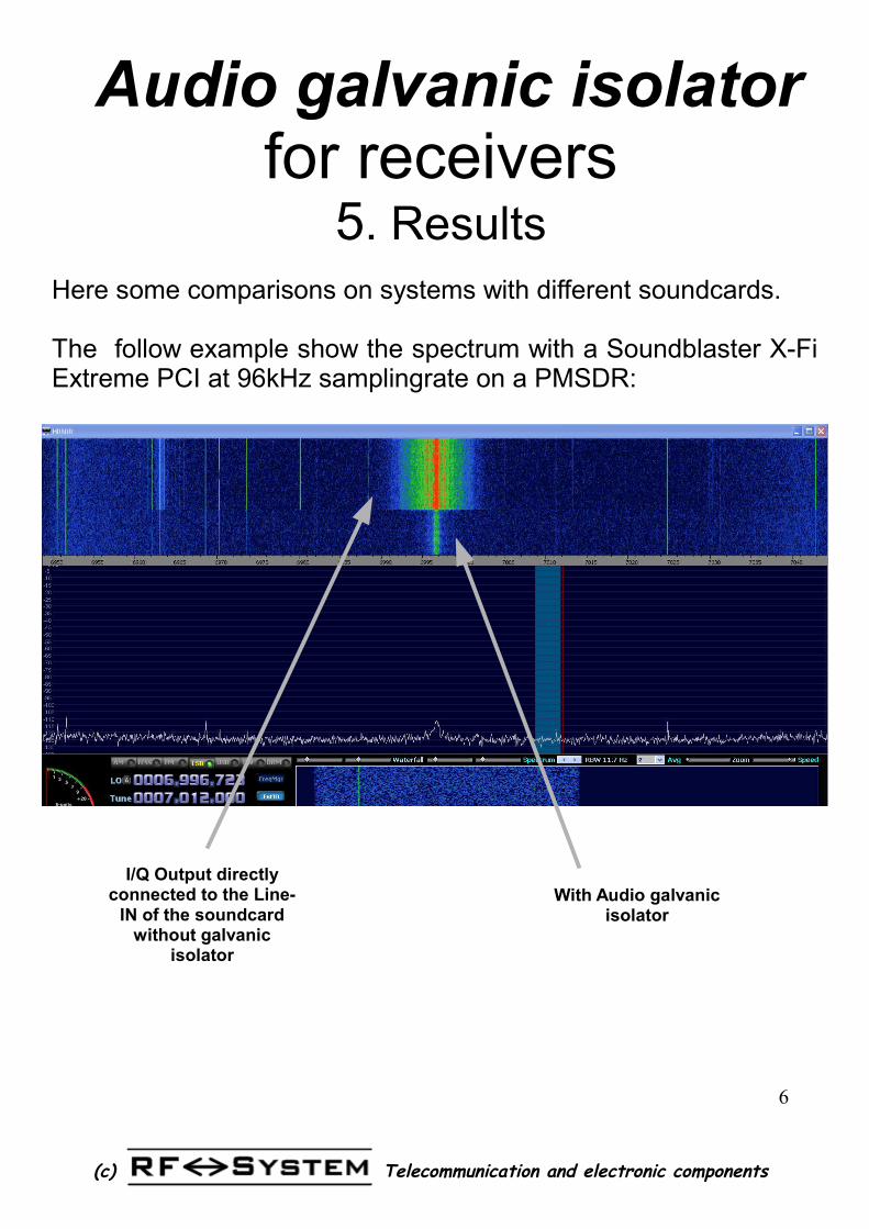
5. ResultsHere some comparisons on systems with different soundcards.
The follow example show the spectrum with a Soundblaster X-Fi Extreme PCI at 96kHz samplingrate on a PMSDR:
I/Q Output directly connected to the Line-
IN of the soundcard without galvanic
isolator
With Audio galvanic isolator
7
Telecommunication and electronic components(c)
Audio galvanic isolatorfor receivers
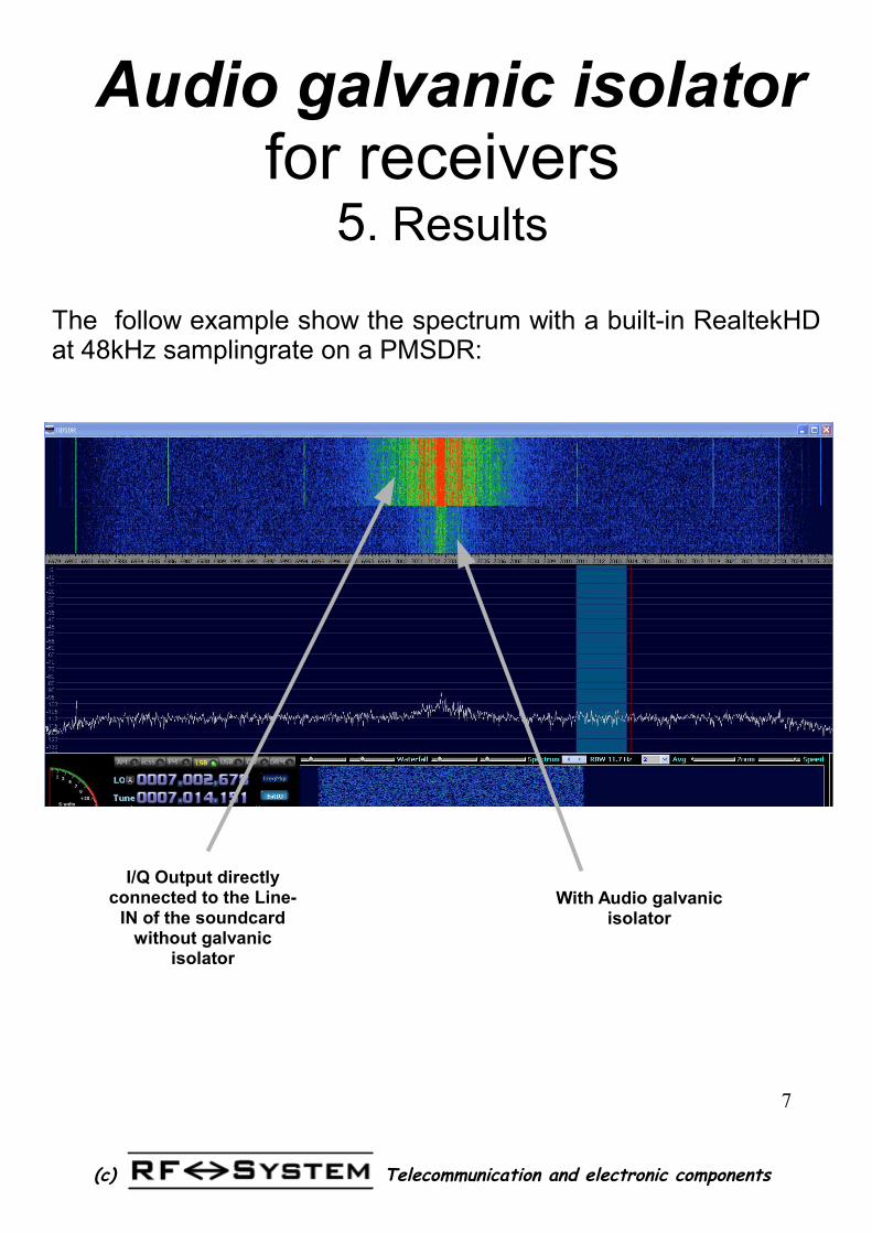
5. Results
The follow example show the spectrum with a built-in RealtekHD at 48kHz samplingrate on a PMSDR:
I/Q Output directly connected to the Line-
IN of the soundcard without galvanic
isolator
With Audio galvanic isolator
8
Telecommunication and electronic components(c)
Audio galvanic isolatorfor receivers
5. Results
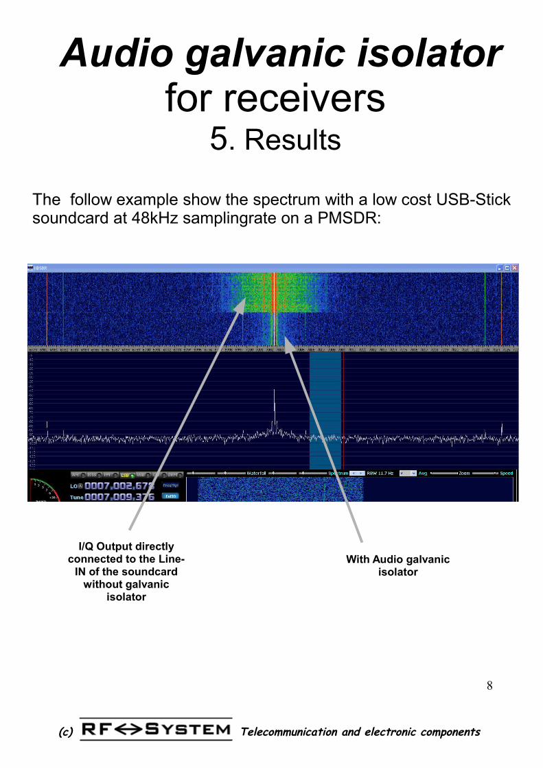
The follow example show the spectrum with a low cost USB-Stick soundcard at 48kHz samplingrate on a PMSDR:
I/Q Output directly connected to the Line-
IN of the soundcard without galvanic
isolator
With Audio galvanic isolator
9
Telecommunication and electronic components(c)
Audio galvanic isolatorfor receivers
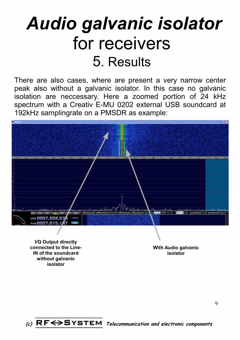
5. ResultsThere are also cases, where are present a very narrow center peak also without a galvanic isolator. In this case no galvanic isolation are neccessary. Here a zoomed portion of 24 kHz spectrum with a Creativ E-MU 0202 external USB soundcard at 192kHz samplingrate on a PMSDR as example:
I/Q Output directly connected to the Line-
IN of the soundcard without galvanic
isolator
With Audio galvanic isolator
10
Telecommunication and electronic components(c)
Audio galvanic isolator For soundcards and SDR
receivers6. Technical specifications
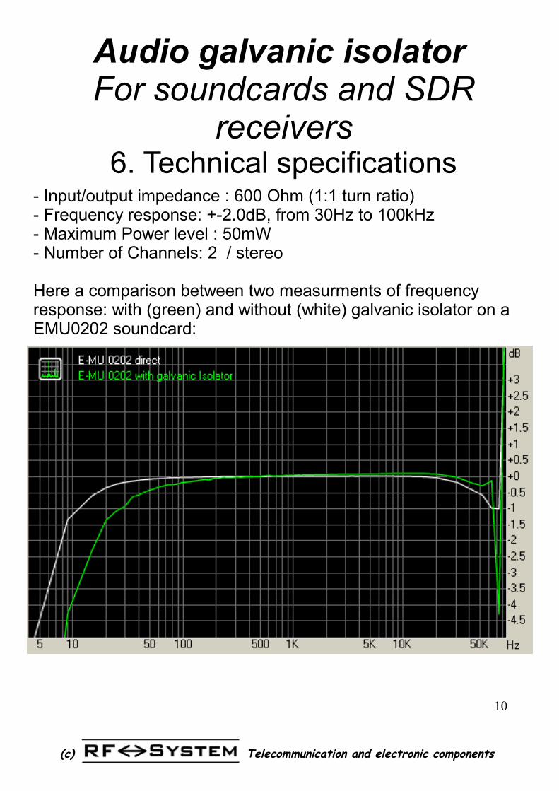
- Input/output impedance : 600 Ohm (1:1 turn ratio)- Frequency response: +-2.0dB, from 30Hz to 100kHz- Maximum Power level : 50mW- Number of Channels: 2 / stereo
Here a comparison between two measurments of frequency response: with (green) and without (white) galvanic isolator on a EMU0202 soundcard: