FNW BP IOM 85392725 07-15 (E) - Flowserve...BP USER INSTRUCTIONS ENGLISH 85392725 07-15 (E) Page 5...
44
USER INSTRUCTIONS Niigata Worthington™ BP Installation Operation Maintenance Multi-stage, horizontal, barrel pump PCN= 85392725 07-15 (E) Original instructions. These instructions must be read prior to installing, operating, using and maintaining this equipment.
Transcript of FNW BP IOM 85392725 07-15 (E) - Flowserve...BP USER INSTRUCTIONS ENGLISH 85392725 07-15 (E) Page 5...

USER INSTRUCTIONS
Niigata Worthington™ BP Installation
Operation Maintenance Multi-stage, horizontal, barrel pump
PCN= 85392725 07-15 (E) Original instructions.
These instructions must be read prior to installing , operating, using and maintaining this equipment.

BP USER INSTRUCTIONS ENGLISH 85392725 07-15 (E)
Page 2 of 44 flowserve.com
CONTENTS Page
1 INTRODUCTION AND SAFETY ....................... 4 1.1 General ....................................................... 4 1.2 CE marking and approvals ........................... 4 1.3 Disclaimer ................................................... 4 1.4 Copyright ..................................................... 4 1.5 Duty conditions ............................................ 4 1.6 Safety .......................................................... 5 1.7 Nameplate and safety labels ........................ 8 1.8 Specific machine performance ..................... 8 1.9 Noise level ................................................... 9
2 TRANSPORT AND STORAGE ....................... 10 2.1 Consignment receipt and unpacking .......... 10 2.2 Handling .................................................... 10 2.3 Lifting ........................................................ 10 2.4 Storage ..................................................... 10 2.5 Recycling and end of product life ............... 10
3 DESCRIPTION ............................................... 11 3.1 Configurations ........................................... 11 3.2 Name nomenclature .................................. 11 3.3 Design of major parts ................................. 11 3.4 Performance and operating limits ............... 12
4 INSTALLATION .............................................. 14 4.1 Location .................................................... 14 4.2 Part assemblies ......................................... 14 4.3 Foundation ................................................ 14 4.4 Grouting .................................................... 14 4.5 Initial alignment ......................................... 15 4.6 Piping ........................................................ 16 4.7 Electrical connections ................................ 19 4.8 Final shaft alignment check ....................... 19 4.9 Protection systems .................................... 19
5 COMMISSIONING, START-UP, OPERATION AND SHUTDOWN .......................................... 20
5.1 Pre-commissioning procedure ................... 20 5.2 Pump lubricants ......................................... 20 5.3 Impeller clearance ..................................... 21 5.4 Direction of rotation ................................... 21 5.5 Guarding ................................................... 21 5.6 Priming and auxiliary supplies .................... 21 5.7 Starting the pump ...................................... 22 5.8 Running the pump ..................................... 22 5.9 Stopping and shutdown ............................. 22 5.10 Hydraulic, mechanical and electrical duty ... 23
6 MAINTENANCE ............................................. 24 6.1 General ..................................................... 24 6.2 Maintenance schedule ............................... 24 6.3 Spare parts ................................................ 25 6.4 Recommended spares ............................... 26 6.5 Tools required ............................................ 26 6.6 Fastener torques ....................................... 27 6.7 Disassembly .............................................. 27
6.8 Examination of parts ................................. 29 6.9 Replacement of pressed in components .... 31 6.10 Assembly .................................................. 31
7 FAULTS; CAUSES AND REMEDIES .............. 37
8 PARTS LISTS AND DRAWINGS .................... 40 8.1 Section & Parts List ................................... 40 8.2 General arrangement drawing ................... 42
9 CERTIFICATION ............................................ 42
10 OTHE RELEVANT DOCMENTS AND MANUALS ..................................................... 42
10.1 Supplementary User Instruction manuals .. 42 10.2 Change notes ........................................... 42 10.3 Additional sources of information ............... 42 10.4 Technical Data Sheet ................................ 43

BP USER INSTRUCTIONS ENGLISH 85392725 07-15 (E)
Page 3 of 44 flowserve.com
INDEX Page
Page
Alignment, coupling (4.5.2) ................................. 15 Assembly (6.9) ................................................... 31 ATEX Marking (1.6.4.2) ........................................ 7 Bearing Sizes (5.2.1) ......................................... 20 CE marking and approvals (1.2) ........................... 4 Certification (9) .................................................. 42 Change notes (10.2) .......................................... 42 Commissioning and operation (5) ....................... 20 Compliance, ATEX (1.6.4.1) ................................. 6 Configurations (3.1) ........................................... 11 Copyright (1.4) ..................................................... 4 Design of major parts (3.3) ................................. 11 Direction of rotation (5.4) .................................... 21 Disassembly (6.7) .............................................. 27 Disclaimer (1.3) .................................................... 4 Dismantling (6.7, Disassembly) .......................... 27 Drawings (8) ...................................................... 40 Duty conditions (1.5) ............................................ 4 Electrical connections (4.7) ................................ 19 End of product life (2.5) ...................................... 10 Examination of parts (6.8) .................................. 29 Fastener torques (6.6) ....................................... 27 Faults, causes and remedies (7) ........................ 37 Foundation (4.3) ................................................ 14 General arrangement drawing (8.2) .................... 42 General assembly drawings (8) .......................... 40 Grouting (4.4) .................................................... 14 Guarding (5.5) ................................................... 21 Handling (2.2) .................................................... 10 Hydraulic, mechanical and electrical duty (5.9) ... 23 Inspection (6.2.1 and 6.2.2) ................................ 25 Installation (4) .................................................... 14 Lifting (2.3) ........................................................ 10 Location (4.1) ..................................................... 14 Lubrication schedule (5.2.2) ............................... 20 Maintanence (6) ................................................. 24
Maintenance schedule (6.2) ............................... 24 Name nomenclature (3.2) ................................... 11 Nameplate (1.7.1) ................................................ 8 Nozzle loads (4.6.4) ........................................... 17 Operating limits (3.4.1) ....................................... 12 Ordering of spares (6.3.1) .................................. 25 Part assemblies (4.2) ......................................... 14 Parts list (8) ....................................................... 40 Performance (3.4) .............................................. 12 Piping (4.6) ........................................................ 16 Pre-commissioning (5.1) .................................... 20 Priming and auxiliary supplies(5.5) ..................... 21 Protection systems (4.9) ..................................... 19 Reassembly (6.9, Assembly) .............................. 31 Receipt and unpacking (2.1) ............................... 10 Recommended fill quantities (see 5.2.2) ............. 20 Recommended spares (6.4) ............................... 26 Recycling (2.5) ................................................... 10 Running the pump (5.7)...................................... 22 Safety action (1.6.3) ............................................. 5 Safety labels (1.7.2) ............................................. 8 Safety markings (1.6.1) ........................................ 5 Sectional drawings (8) ........................................ 40 Sound pressure level (1.9, Noise level) ................ 9 Sources, additional information (10.3) ................ 42 Spare parts (6.3) ................................................ 25 Specific machine performance (1.8) ..................... 8 Starting the pump (5.6)....................................... 22 Stopping and shutdown (5.8) .............................. 22 Storage of spares (6.3.2) .................................... 26 Storage, pump (2.4) ........................................... 10 Supplementary User Instructions (10.1) .............. 42 Thermal expansion (4.5.1) ................................. 15 Tools required (6.5) ............................................ 26 Torques for fasteners (6.6) ................................. 27 Trouble-shooting (see 7) .................................... 37

BP USER INSTRUCTIONS ENGLISH 85392725 07-15 (E)
Page 4 of 44 flowserve.com
1 INTRODUCTION AND SAFETY 1.1 General
These instructions must always be kept close to the product's operating location or directly with the product. Flowserve products are designed, developed and manufactured with state-of-the-art technologies in modern facilities. The unit is produced with great care and commitment to continuous quality control, utilising sophisticated quality techniques and safety requirements. Flowserve is committed to continuous quality improvement and being at service for any further information about the product in its installation and operation or about its support products, repair and diagnostic services. These instructions are intended to facilitate familiarization with the product and its permitted use. Operating the product in compliance with these instructions is important to help ensure reliability in service and avoid risks. The instructions may not take into account local regulations; ensure such regulations are observed by all, including those installing the product. Always coordinate repair activity with operations personnel, and follow all plant safety requirements and applicable safety and health laws/regulations.
These instructions must be read prior to installing, operating, using and maintaining the equipment in any region worldwide. The equipment must not be put into service until all the conditions relating to safety noted in the instructions, have been met. Failure to follow and apply the present user instructions is considered to be misuse. Personal injury, product damage, delay or failure caused by misuse are not covered by the Flowserve warranty. 1.2 CE marking and approvals It is a legal requirement that machinery and equipment put into service within certain regions of the world shall conform with the applicable CE Marking Directives covering Machinery and, where applicable, Low Voltage Equipment, Electromagnetic Compatibility (EMC), Pressure Equipment Directive (PED) and Equipment for Potentially Explosive Atmospheres (ATEX). Where applicable, the Directives and any additional Approvals, cover important safety aspects relating to machinery and equipment and the satisfactory provision
of technical documents and safety instructions. Where applicable this document incorporates information relevant to these Directives and Approvals. To confirm the Approvals applying and if the product is CE marked, check the serial number plate markings and the Certification. (See section 9, Certification.) 1.3 Disclaimer Information in these User Instructions is believed to be reliable. In spite of all the efforts of Flowserve Corporation to provide sound and all necessary information the content of this manual may appear insufficient and is not guaranteed by Flowserve as to its completeness or accuracy . Flowserve manufactures products to exacting International Quality Management System Standards as certified and audited by external Quality Assurance organisations. Genuine parts and accessories have been designed, tested and incorporated into the products to help ensure their continued product quality and performance in use. As Flowserve cannot test parts and accessories sourced from other vendors the incorrect incorporation of such parts and accessories may adversely affect the performance and safety features of the products. The failure to properly select, install or use authorised Flowserve parts and accessories is considered to be misuse. Damage or failure caused by misuse is not covered by the Flowserve warranty. In addition, any modification of Flowserve products or removal of original components may impair the safety of these products in their use. 1.4 Copyright All rights reserved. No part of these instructions may be reproduced, stored in a retrieval system or transmitted in any form or by any means without prior permission of Flowserve Pump Division. 1.5 Duty conditions This product has been selected to meet the specifications of your purchaser order. The acknowledgement of these conditions has been sent separately to the Purchaser. A copy should be kept with these instructions.
The product must not be operated beyond the parameters specified for the application. If there is any doubt as to the suitability of the product for the application intended, contact Flowserve for advice, quoting the serial number. If the conditions of service on your purchase order are going to be changed (for example liquid pumped,

BP USER INSTRUCTIONS ENGLISH 85392725 07-15 (E)
Page 5 of 44 flowserve.com
temperature or duty) it is requested that the user seeks the written agreement of Flowserve before start up. 1.6 Safety 1.6.1 Summary of safety markings These User Instructions contain specific safety markings where non-observance of an instruction would cause hazards. The specific safety markings are:
This symbol indicates electrical safety instructions where non-compliance will involve a high risk to personal safety or the loss of life.
This symbol indicates safety instructions where non-compliance would affect personal safety and could result in loss of life.
This symbol indicates “hazardous and toxic fluid” safety instructions where non-compliance would affect personal safety and could result in loss of life.
This symbol indicates safety instructions where non-compliance will involve some risk to safe operation and personal safety and would damage the equipment or property.
This symbol indicates explosive atmosphere zone marking according to ATEX. It is used in safety instructions where non-compliance in the hazardous area would cause the risk of an explosion.
This symbol is used in safety instructions to remind not to rub non-metallic surfaces with a dry cloth; ensure the cloth is damp. It is used in safety instructions where non-compliance in the hazardous area would cause the risk of an explosion.
This sign is not a safety symbol but indicates an important instruction in the assembly process. 1.6.2 Personnel qualification and training All personnel involved in the operation, installation, inspection and maintenance of the unit must be qualified to carry out the work involved. If the personnel in question do not already possess the necessary knowledge and skill, appropriate training and instruction must be provided. If required the operator may commission the manufacturer/supplier to provide applicable training. Always coordinate repair activity with operations and health and safety personnel, and follow all plant safety requirements and applicable safety and health laws and regulations.
1.6.3 Safety action This is a summary of conditions and actions to help prevent injury to personnel and damage to the environment and to equipment. For products used in potentially explosive atmospheres section 1.6.4 also applies.
NEVER DO MAINTENANCE WORK WHEN THE UNIT IS CONNECTED TO POWER
GUARDS MUST NOT BE REMOVED WHILE THE PUMP IS OPERATIONAL
DRAIN THE PUMP AND ISOLATE PIPEWORK BEFORE DISMANTLING THE PUMP The appropriate safety precautions should be taken where the pumped liquids are hazardous.
FLUORO-ELASTOMERS (When fitted.) When a pump has experienced temperatures over 250 ºC (482 ºF), partial decomposition of fluoro-elastomers (example: Viton) will occur. In this condition these are extremely dangerous and skin contact must be avoided.
HANDLING COMPONENTS Many precision parts have sharp corners and the wearing of appropriate safety gloves and equipment is required when handling these components. To lift pieces that cannot be comfortably lifted by hand use a crane appropriate for the mass and in accordance with current local regulations.
THERMAL SHOCK Rapid changes in the temperature of the liquid within the pump can cause thermal shock, which can result in damage or breakage of components and should be avoided.
NEVER APPLY HEAT TO REMOVE IMPELLER Trapped lubricant or vapour could cause an explosion.
HOT (and cold) PARTS If hot or freezing components or auxiliary heating supplies can present a danger to operators and persons entering the immediate area action must be taken to avoid accidental contact. If complete protection is not possible, the machine access must be limited to maintenance staff only, with clear visual warnings and indicators to those entering the immediate area. Note: bearing housings must not be insulated and drive motors and bearings may be hot. If the temperature is greater than 80 ºC (176 ºF) o r below -5 ºC (23 ºF) in a restricted zone, or exceed s local regulations, action as above shall be taken.
BP USER INSTRUCTIONS ENGLISH 85392725 07-15 (E)
Page 6 of 44 flowserve.com
HAZARDOUS LIQUIDS When the pump is handling hazardous liquids care must be taken to avoid exposure to the liquid by appropriate siting of the pump, limiting personnel access and by operator training. If the liquid is flammable and or explosive, strict safety procedures must be applied. Gland packing must not be used when pumping hazardous liquids.
PREVENT EXCESSIVE EXTERNAL PIPE LOAD Do not use pump as a support for piping. Do not mount expansion joints, so that their force, due to internal pressure, acts on the pump flange, unless allowed by Flowserve in writing.
NEVER RUN THE PUMP DRY
ENSURE CORRECT LUBRICATION (See section 5, Commissioning, startup, operation and shutdown.)
ONLY CHECK DIRECTION OF MOTOR ROTATION WITH COUPLING ELEMENT/ PINS REMOVED Starting in reverse direction of rotation will damage the pump.
START THE PUMP WITH OUTLET VALVE PART OPENED (Unless otherwise instructed at a specific point in the User Instructions.) This is recommended to minimize the risk of overloading and damaging the pump or motor at full or zero flow. Pumps may be started with the valve further open only on installations where this situation cannot occur. The pump outlet control valve may need to be adjusted to comply with the duty following the run-up process. (See section 5, Commissioning start-up, operation and shutdown.)
INLET VALVES TO BE FULLY OPEN WHEN PUMP IS RUNNING Running the pump at zero flow or below the recommended minimum flow continuously will cause damage to the pump and mechanical seal.
DO NOT RUN THE PUMP AT ABNORMALLY HIGH OR LOW FLOW RATES Operating at a flow rate higher than normal or at a flow rate with no back pressure on the pump may overload the motor and cause cavitation. Low flow rates may cause a reduction in pump/bearing life, overheating of the pump, instability and cavitation/vibration. 1.6.4 Products used in potentially explosive
atmospheres
Measures are required to: • Avoid excess temperature • Prevent build up of explosive mixtures • Prevent the generation of sparks • Prevent leakages • Maintain the pump to avoid hazard The following instructions for pumps and pump units when installed in potentially explosive atmospheres must be followed to help ensure explosion protection. For ATEX both electrical and non-electrical equipment must meet the requirements of European Directive 94/9/EC. Always observe the regional legal Ex requirements e.g. Ex electrical items outside the EU may be required Certified to other than ATEX e.g. IECEx, UL. 1.6.4.1 Scope of compliance
Use equipment only in the zone for which it is appropriate. Always check that the driver, drive coupling assembly, seal and pump equipment are suitably rated and/or certified for the classification of the specific atmosphere in which they are to be installed. Where Flowserve has supplied only the bare shaft pump, the Ex rating applies only to the pump. The party responsible for assembling the ATEX pump set shall select the coupling, driver and any additional equipment, with the necessary CE Certificate/ Declaration of Conformity establishing it is suitable for the area in which it is to be installed. The output from a variable frequency (speed) drive (VFD) can cause additional heating effects in the motor and so, for pumps sets with a VFD, the ATEX Certification for the motor must state that it is covers the situation where electrical supply is from the VFD. This particular requirement still applies even if the VFD is in a safe area.

BP USER INSTRUCTIONS ENGLISH 85392725 07-15 (E)
Page 7 of 44 flowserve.com
1.6.4.2 Marking An example of ATEX equipment marking is shown below. The actual classification of the pump will be engraved on the nameplate.
II 2 GD c IIC 135 ºC (T4)
Equipment Group I = Mining II = Non-mining
Category 2 or M2 = high level protection 3 = normal level of protection
Gas and/or dust G = Gas D = Dust
c = Constructional safety (in accordance with EN13463-5)
Gas Group (Equipment Category 2 only) IIA – Propane (typical) IIB – Ethylene (typical) IIC – Hydrogen (typical)
Maximum surface temperature (Temperature Class) (see section 1.6.4.3.) 1.6.4.3 Avoiding excessive surface
temperatures
ENSURE THE EQUIPMENT TEMPERATURE CLASS IS SUITABLE FOR THE HAZARD ZONE Pumps have a temperature class as stated in the ATEX Ex rating on the nameplate. These are based on a maximum ambient of 40 ºC (104 ºF); refer to Flowserve for higher ambient temperatures. The surface temperature on the pump is influenced by the temperature of the liquid handled. The maximum permissible liquid temperature depends on the temperature class and must not exceed the values in the table that follows. The temperature rise at the seals and bearings and due to the minimum permitted flow rate is taken into account in the temperatures stated.
Temperature class to
EN13463-1
Maximum surface
temperature permitted
Temperature limit of liquid handled (* depending on material and construction
variant - check which is lower)
T6 T5 T4 T3 T2 T1
85 °C (185 °F) 100 °C (212 °F) 135 °C (275 °F) 200 °C (392 °F) 300 °C (572 °F) 450 °C (842 °F)
Consult Flowserve Consult Flowserve 115 °C (239 °F) * 180 °C (356 °F) * 275 °C (527 °F) * 400 °C (752 °F) *
The responsibility for compliance with the specified maximum liquid temperature is with the plant operator. Temperature classification “Tx” is used when the liquid temperature varies and when the pump is required to be used in differently classified potentially explosive atmospheres. In this case the user is responsible for ensuring that the pump surface temperature does not exceed that permitted in its actual installed location. Do not attempt to check the direction of rotation with the coupling element/pins fitted due to the risk of severe contact between rotating and stationary components. Where there is any risk of the pump being run against a closed valve generating high liquid and casing external surface temperatures it is recommended that users fit an external surface temperature protection device. Avoid mechanical, hydraulic or electrical overload by using motor overload trips, temperature monitor or a power monitor and make routine vibration monitoring checks. In dirty or dusty environments, regular checks must be made and dirt removed from areas around close clearances, bearing housings and motors. 1.6.4.4 Preventing the build up of explosive
mixtures
ENSURE THE PUMP IS PROPERLY FILLED AND VENTED AND DOES NOT RUN DRY Ensure the pump and relevant suction and discharge pipeline system is totally filled with liquid at all times during the pump operation, so that an explosive atmosphere is prevented. In addition it is essential to make sure that seal chambers, auxiliary shaft seal systems and any heating and cooling systems are properly filled. If the operation of the system cannot avoid this condition the fitting of an appropriate dry run protection device is recommended (for example liquid detection or a power monitor).

BP USER INSTRUCTIONS ENGLISH 85392725 07-15 (E)
Page 8 of 44 flowserve.com
To avoid potential hazards from fugitive emissions of vapour or gas to atmosphere the surrounding area must be well ventilated. 1.6.4.5 Preventing sparks
To prevent a potential hazard from mechanical contact, the coupling guard must be non-sparking. To avoid the potential hazard from random induced current generating a spark, the earth contact on the baseplate must be used.
Avoid electrostatic charge: do not rub non-metallic surfaces with a dry cloth; ensure cloth is damp. For ATEX the coupling must be selected to comply with 94/9/EC. Correct alignment must be maintained. Additional requirement for metallic pumps on non-metallic baseplates When metallic components are fitted on a non-metallic baseplate they must be individually earthed. 1.6.4.6 Preventing leakage
The pump must only be used to handle liquids for which it has been approved to have the correct corrosion resistance. Avoid entrapment of liquid in the pump and associated piping due to closing of suction and discharge valves, which could cause dangerous excessive pressures to occur if there is heat input to the liquid. This can occur if the pump is stationary or running. Bursting of liquid containing parts due to freezing must be avoided by draining or protecting the pump and ancillary systems. Where there is the potential hazard of a loss of a seal barrier fluid or external flush, the fluid must be monitored. If leakage of liquid to atmosphere can result in a hazard, the installation of a liquid detection device is recommended. 1.6.4.7 Maintenance to avoid the hazard
CORRECT MAINTENANCE IS REQUIRED TO AVOID POTENTIAL HAZARDS WHICH GIVE A RISK OF EXPLOSION The responsibility for compliance with maintenance instructions is with the plant operator.
To avoid potential explosion hazards during maintenance, the tools, cleaning and painting materials used must not give rise to sparking or adversely affect the ambient conditions. Where there is a risk from such tools or materials, maintenance must be conducted in a safe area. It is recommended that a maintenance plan and schedule is adopted. (See section 6, Maintenance.) 1.7 Nameplate and safety labels 1.7.1 Nameplate The following nameplate will be found on the bearing housing [3200] of the pump.
1.7.2 Safety labels The pump will be supplied with all relevant safety labels that are required for the safe operation of the pump. 1.8 Specific machine performance For performance parameters see section 1.5, Duty conditions. Where performance data has been supplied separately to the purchaser these should be obtained and retained with these User Instructions if required.

BP USER INSTRUCTIONS ENGLISH 85392725 07-15 (E)
Page 9 of 44 flowserve.com
1.9 Noise level Attention must be given to the exposure of personnel to the noise, and local legislation will define when guidance to personnel on noise limitation is required, and when noise exposure reduction is mandatory. This is typically 80 to 85 dBA. The usual approach is to control the exposure time to the noise or to enclose the machine to reduce emitted sound. You may have already specified a limiting noise level when the equipment was ordered, however if no noise requirements were defined, then attention is drawn to the following table to give an indication of equipment noise level so that you can take the appropriate action in your plant. Pump noise level is dependent on a number of operational factors, flow rate, pipework design and acoustic characteristics of the building, and so the values given are subject to a 3 dBA tolerance and cannot be guaranteed. Similarly the motor noise assumed in the “pump and motor” noise is that typically expected from standard and high efficiency motors when on load directly driving the pump. Note that a motor driven by an inverter may show an increased noise at some speeds. If a pump unit only has been purchased for fitting with your own driver then the “pump only” noise levels in the table should be combined with the level for the driver obtained from the supplier. Consult Flowserve or a noise specialist if assistance is required in combining the values. It is recommended that where exposure approaches the prescribed limit, then site noise measurements should be made. The values are in sound pressure level LpA at 1 m (3.3 ft) from the machine, for “free field conditions over a reflecting plane”. For estimating sound power level LWA (re 1 pW) then add 14 dBA to the sound pressure value.
Motor size and speed
kW (hp)
Typical sound pressure level L pA at 1 m reference 20 µPa, dBA
3 550 r/min 2 900 r/min
Pump only
Pump and
motor
Pump only
Pump and
motor 30 (40) 79 83 79 83
37 (50) 80 83 80 83 45 (60) 81 85 81 85
55 (75) 82 85 82 85 75 (100) 84 87 84 87
90 (120) 84 87 84 87
110 (150) 85 90 85 90
132 (180) 85 90 85 90
150 (200) 86 90 86 90
185 (250) 86 90 86 90 200 (270) 87 90 87 90
315 (420) 87 90 87 90 400 (535) 89 92 89 92
475 (635) 89 92 89 92 630 (845) 91 92 91 92
800 (1070) 92 93 92 93
1000 (1340) 93 93 93 93
1120 (1500) 93 93 93 93
1250 (1675) 94 94 94 94
1500 (2000) 95 95 95 95 1700 (2280) 95 95 95 95
1800 (2400) 96 96 96 96 2000 (2680) 96 96 96 96

BP USER INSTRUCTIONS ENGLISH 85392725 07-15 (E)
Page 10 of 44 flowserve.com
2 TRANSPORT AND STORAGE 2.1 Consignment receipt and unpacking Immediately after receipt of the equipment it must be checked against the delivery/shipping documents for its completeness and that there has been no damage in transportation. Any shortage and/or damage must be reported immediately to Flowserve Pump Division and must be received in writing within one month of receipt of the equipment. Later claims cannot be accepted. Check any crate, boxes or wrappings for any accessories or spare parts that may be packed separately with the equipment or attached to side walls of the box or equipment. Each product has a unique serial number. Check that this number corresponds with that advised and always quote this number in correspondence as well as when ordering spare parts or further accessories. 2.2 Handling Boxes, crates, pallets or cartons may be unloaded using fork lift vehicles or slings dependent on their size and construction. 2.3 Lifting
A crane must be used for all pump sets.. Fully trained personnel must carry out lifting, in accordance with local regulations. Slings, ropes and other lifting gear should be positioned where they cannot slip and where a balanced lift is obtained.
2.3.1 Bare pump The bare pump should be lifted by the lifting eye as shown: Before lifting the driver alone, refer to the manufacturer’s instructions. 2.4 Storage
Store the pump in a clean, dry location away from vibration. Leave piping connection covers in place to keep dirt and other foreign material out of pump casing. Turn pump at intervals to prevent brinelling of the bearings and the seal faces, if fitted, from sticking. The pump may be stored as above for up to 6 months. Consult Flowserve for preservative actions when a longer storage period is needed. 2.5 Recycling and end of product life At the end of the service life of the product or its parts, the relevant materials and parts should be recycled or disposed of using an environmentally acceptable method and local requirements. If the product contains substances that are harmful to the environment, these should be removed and disposed of in accordance with current regulations. This also includes the liquids and/or gases that may be used in the "seal system" or other utilities.
Make sure that hazardous substances are disposed of safely and that the correct personal protective equipment is used. The safety specifications must be in accordance with the current regulations at all times.

BP USER INSTRUCTIONS ENGLISH 85392725 07-15 (E)
Page 11 of 44 flowserve.com
3 DESCRIPTION 3.1 Configurations The BP type barrel pump is a process pump that is operated under high pressure/high temperature processing conditions. The casing consists of an outer casing (casing barrel) and an inner casing (diffusers). As the suction and discharge nozzle are made of forged carbon steel and integral with the casing by welding, the pump is able to be dismantled and reassembled without disturbing suction and discharge piping. 3.2 Name nomenclature The pump size will be engraved on the nameplate typically as below:
6BP-1411S
• “6” = Nominal discharge size in inches • “BP” = Pump Designation • ”14” = Nominal Impeller size in inches • “11” = Number of Stages, 4-14 • “S” = Special Impeller Design 3.2.1 Discharge sizes 2, 3, 4, 6, and 8 Inches 3.2.2 Pump Designations BP= Single Suction Impeller BPD= Double Suction Impeller 3.2.3 Impeller sizes 8, 9, 10, 11, 12, 14, and 18 Inches 3.3 Design of major parts Refer to Section 8 for sectional drawings. 3.3.1 Outer Casing(Casing Barrel) A carbon controlled forged steel is used for the outer casing. The outer casing is supported at the horizontal centreline of the pump to minimize coupling misalignment. The barrel is designed as a whole to reduce any stress concentration by applying FEM analysis for the optimum design. 3.3.2 Inner Casing(Diffuser, Inner Element) Inner casing consists of stage pieces (1460.1-3) and diffusers (1411, 1412, 1413). The inner casing is designed for easy disassembling and assembling since the diffusers and stage pieces are in one integrated configuration. Each diffuser is mounted with a shrink fit and a dowel pin to prevent the rotation of the diffuser. The entire inner
element(diffuser) is pushed and secured axially against the shoulder of the casing barrel with a circular element spring(4260) located between last stage piece and discharge head due to high discharge pressure generated during pump operation. The entire inner element is also prevented from rotating by a dowel pin located between last stage diffuser and discharge head. The inner assembly expands and contracts freely due to temperature variations without introducing thermal stress in any of the pump parts. Self-flushing liquid for mechanical seals is extracted from liquid in the first stage piece through the flow passage drilled in the first stage and the casing barrel. 3.3.3 Impellers and Wearing rings Impellers are of the single suction closed type. They are dynamically balanced individually and keyed to the shaft. They are also secured on the shaft in position with a spilt ring and a Spirolox ring, if required. The first stage impeller is usually designed with a lager inlet to reduce N.P.S.H requirements. The diffuser rings are made of hardened chrome steel. Each ring is pressed into its diffuser. If required, replaceable impeller wearing rings can be furnished. 3.3.4 Shaft The shaft is grooved to accommodate the split rings, spirolox rings, if required, and a thrust ring for positioning impellers and balancing drum. 3.3.5 Balancing Drum The pump is hydraulically balanced by a balancing drum and balancing ring. The balancing drum is secured against axial movement by a thrust ring and against rotational movement by keys. 3.3.6 Discharge Head The discharge head is subjected to the full discharge pressure of the pump. It is made of a forged carbon steel using a Spiral Wound GASKET as the high pressure seal. The discharge head contains the balancing ring and supports the outboard stuffing box and thrust end bearing housing. 3.3.7 Stuffing Box and Suction Head Outboard stuffing box and inboard suction head are fixed to the discharge head and the casing barrel respectively with casing studs and nuts. Both of them have cooling water chambers or steam jackets and are supplied with the mechanical seals suitable for the conditions of service. For details about the installed mechanical seals, refer to manufacturer’s instructions at the appendix.

BP USER INSTRUCTIONS ENGLISH 85392725 07-15 (E)
Page 12 of 44 flowserve.com
3.3.8 Bearings The BP pump is equipped with heavy duty, externally mounted antifriction bearings or with babbitted sleeve and Kingsbury type thrust bearing depending on size of pump and application. In the case of the anti-friction bearing, the outboard or thrust bearing is a double row, angular contact ball bearings mounted back to back. It has a shrink fit on the shaft and is secured axially with a bearing nut and lock-washer. The outer races are contained between a shoulder in the bearing housing and a spigot on the thrust bearing cover to prevent end movement. All expansion due to heat is directed away from the thrust bearing. The lubricating oil reservoir is water-cooled. The inboard or line bearing also has a shrink fit on the shaft and is of the single row anti-friction type. Clearance in the bearing housing allows the outer race to move axially to prevent shaft bending or binding of internal parts as a result of axial shaft expansion due to heat. Slight rotation of the outer race in the housing is actually beneficial in extending bearing life should it occur. All rotor expansion due to heat occurs away from the thrust bearing (toward the driver). In the thrust and line bearing housing, positive circulation of lubricating oil is assured by the oil flinger and the trough on the inside of the bearing housing. Proper oil level in the oil reservoir is maintained by the constant level oiler. For the sleeve-Kingsbury arrangement, the sleeve bearings used are the thin wall automotive type. The Kingsbury bearing is a JHJ double six shoe self equalizing type. 3.3.9 Couplings An all-metal flexible coupling of the spacer type is standard for connecting pump and driver shafts on all sizes of BP or WCH pumps. This coupling permits dismantling the pump without disturbing the driver and casing barrel. For operating instruction and maintenance of coupling, if supplied. refer to the manufacturer’s instruction in the appendix. 3.3.10 Accessories Accessories may be fitted when specified by the customer. 3.4 Performance and operating limits This product has been selected to meet the specifications of the purchase order. See section 1.5. The following data is included as additional information to help with your installation. It is typical, and factors such as temperature, materials, and seal type may influence this data. If required, a definitive
statement for your particular application can be obtained from Flowserve. 3.4.1 Operating limits Maximum operating temperature: 425°C (820°F) Maximum pump speed: 6000rpm Maximum operating pressure: 29 MPa (4260 psi)

BP USER INSTRUCTIONS ENGLISH 85392725 07-15 (E)
Page 13 of 44 flowserve.com
Notes:

BP USER INSTRUCTIONS ENGLISH 85392725 07-15 (E)
Page 14 of 44 flowserve.com
4 INSTALLATION
Equipment operated in hazardous locations must comply with the relevant explosion protection regulations. See section 1.6.4, Products used in potentially explosive atmospheres. 4.1 Location The pump should be placed so that it is easily accessible for inspection during operation while giving due attention to the desirability of simplifying the suction and discharge piping layout. There should be ample place to allow the use of an overhead crane or other lifting device with sufficient capacity to lift the heavy parts of the unit. Refer to the general arrangement drawing for the pump set. 4.2 Part assemblies On baseplated pump sets the coupling elements are supplied loose. It is the responsibility of the installer to ensure that the pump set is finally lined up as detailed in section 4.5.2, Alignment methods. 4.3 Foundation
There are many methods of installing pump units to their foundations. The correct method depends on the size of the pump unit, its location and noise and vibration limitations. Non-compliance with the provision of correct foundation and installation may lead to failure of the pump and, as such, would be outside the terms of the warranty. Ensure the following are met: a) The baseplate should be mounted onto a firm
foundation, either an appropriate thickness of quality concrete or sturdy steel framework. It should NOT be distorted or pulled down onto the surface of the foundation, but should be supported to maintain the original alignment.
b) Install the baseplate onto packing pieces evenly spaced and adjacent to foundation bolts.
c) Level with shims between baseplate and packing pieces.
d) The pump and driver have been aligned before dispatch however the alignment of pump and motor half coupling must be checked. If this is incorrect, it indicates that the baseplate has become twisted and should be corrected by re-shimming.
e) If not supplied, guarding shall be fitted as necessary to meet the requirements of ISO 12100 and EN953.
4.4 Grouting Grouting provides solid contact between the pump unit and foundation, prevents lateral movement of vibrating equipment and dampens resonant vibrations. 4.4.1 Foundation Preparation a) Chip the surface of the foundation by about 10 to
20 mm (0.40 to 0.80 in). The surface of foundation will be reasonably rough but not so rough as to interfere with proper placing of the grout.
b) Construct mortar beds in order to install the parallel liners as shown on Fig. 4-3. For the position of parallel liners see Fig. 4-1 and Fig. 4-2.
Fig. 4-1
Fig. 4-2
c) Install the parallel liners on the mortar beds, close to the anchor bolt holes as shown on Fig. 4-3. And adjust the level of parallel liners before the mortar has solidified.
Levering point
Liner Base plate
Foundation
Levering point
Anchor bolt
Parallel liners
Taper liners
30-50mm (1.25-2in)
Base plate
Foundation

BP USER INSTRUCTIONS ENGLISH 85392725 07-15 (E)
Page 15 of 44 flowserve.com
Fig. 4-3
d) After the mortar has solidified, locate the other necessary parallel liners and the taper liners on the parallel liners that have been already installed.
e) Install the base plate on the liners. Adjust the position and height of base plate.
f) Perform the levelling of base plate by adjusting the taper liners under the base plate. Place the spirit level on the machined surface of the base plate(pump and driver mounting pads), or on the discharge flange to level in the direction of pump shaft and in the right angle direction of it. The maximum level tolerance shall be 0.2 mm per metre (0.0025 in. per ft).
g) Tighten the anchor bolts firmly. Re-check the levelling of plate and adjust it if necessary.
h) Disconnect the coupling halves by removing the coupling bolts. Then remove the coupling spacer, carry out the preliminary alignment between the pump and driver in accordance with Section 4.5 “Initial Alignment”
Coupling bolts must be left out of the coupling until a final alignment check has been made. 4.4.2 Mortar Pour Carry out the grouting as follows. a) The typical mixture for grouting in a pump base
plate is composed of one part pure portland cement and two parts building sand with sufficient water to cause the mixture to flow freely under the base plate.
b) After alignment work, spot-weld to the taper liners and parallel liners.
c) Build the wooden form around the outside of the base plate to contain the grout.
d) Well-saturate with water on the top of the chipped concrete foundation.
e) Pour mortar through the grout holes on the base plate and fill the inside of the base plate. Use a stiff wire to work the grout and release air pockets.
f) Cover the exposed surfaces with wet burlap which causes slow drying and prevents cracking.
g) Remove the wooden form and smooth the exposed surfaces.
h) It takes several days mortar to solidify completely, although it depends upon ambient temperature, humidity and mortar composition.
i) Connect the suction and discharge pipes to the pump nozzles. Adjust the pipes so that they do not transmit excessive piping force to the pump.
j) Re-check the alignment after the pipes have been connected and realign if necessary.
k) Install the coupling spacer and tighten the coupling bolts.
In general, it is not necessary to align by giving a centre difference between pump and driver shafts, in even high temperature service. However, it is desirable to check the alignment at hot condition immediately after initial operation at actual pumping liquid and temperature has completed. If a centre difference of more than 0.15 mm (0.003in) has been admitted as the result of above check, compensation should be made for change between centres of pump and driver shafts. Then, in case that comparative, high vibration on pump or driver is admitted during operation, carry out re-alignment at hot condition immediately after the pump stopped, at first. 4.5 Initial alignment 4.5.1 Thermal expansion
The pump and motor will normally have to be aligned at ambient temperature with an allowance for thermal expansion at operating temperature. In pump installations involving high liquid temperatures, the unit should be run at the actual operating temperature, shut down and the alignment checked immediately. 4.5.2 Alignment methods
Pump and driver must be isolated electrically and the half couplings disconnected.
The alignment MUST be checked with a dial indicator. Although the pump will have been aligned at the factory it is most likely that this alignment will have been disturbed during transportation or handling. If necessary, align the motor to the pump, not the pump to the motor. Alignment is achieved by adding or removing shims under the motor feet and also moving the motor
50-70mm (2-2.75in)
50-70mm (2-2.75in)
Anchor bolt
Liner Liner
≈50mm (2in)
Mortar
BP USER INSTRUCTIONS ENGLISH 85392725 07-15 (E)
Page 16 of 44 flowserve.com
horizontally as required. In some cases where the alignment cannot be achieved it will be necessary to move the pump before recommencing the above procedure. Proceed as follows. a) Disconnect the coupling halves by removing the
coupling bolts. Then remove the coupling spacer. b) Check the distance between the coupling halves
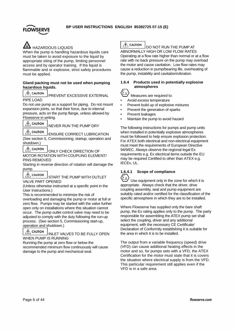
(or pump shafts and driver shaft) against the dimensions shown on the outline drawing supplied. For any necessary adjustment, move the driver. Use the adjusting bolts of base plate at the driver side, if provided
Fig. 4-4 c) Mount the dial indicators, as shown on Fig. 4-4,
ensuring the bracket is rigid and long enough to extend across the space between the coupling hubs, on the driver side coupling.
d) Rest the dial indicator’ probe on the outer diameter of the pump side coupling as shown on Fig. 4-4. Rotate the driver shaft by hand and take reading of dial indicator at every quarter turn to check parallel alignment.
e) Next, after rotating the pump shaft by 180°turn, rotate the driver shaft and take reading of dial indicator at every quarter turn again, and take the average of 1st and 2nd readings.
f) Move the driver by using the adjusting bolts or shim under the driver feet until parallel readings are within 0.05 mm (0.002 in).
g) Rest the dial indicator probe, on the coupling face as shown on Fig. 4-4 for angular alignment. Rotate the driver shaft and take reading of dial indicator in accordance with the same method as the parallel alignment.
h) Adjust the driver side until both parallel and angular readings are within 0.05 mm.
i) After the coupling has been accurately aligned, install the coupling spacer and tighten the coupling bolts.
Permissible misalignment limits at working temperature:
• Parallel alignment - 0.05 mm (0.002 in.) TIR maximum
• Angular alignment - 0.05 mm (0.002 in.) per 305 mm (12 in) TIR maximum
When checking parallel alignment, the total indicator read-out (TIR) shown is twice the value of the actual shaft displacement.
Complete piping as below and see sections 4.7, Final shaft alignment check up to and including section 5, Commissioning, start-up, operation and shutdown, before connecting driver and checking actual rotation. 4.6 Piping
Protective covers are fitted to the pipe connections to prevent foreign bodies entering during transportation and installation. Ensure that these covers are removed from the pump before connecting any pipes. 4.6.1 Suction and discharge pipework
Never use pump as a support for piping. Maximum forces and moments allowed on the pump flanges vary with the pump size and type. To minimize these forces and moments that may, if excessive, cause misalignment, hot bearings, worn couplings, vibration and the possible failure of the pump casing, the following points should be strictly followed: Prevent excessive external pipe load Never draw piping into place by applying force to pump flange connections Do not mount expansion joints so that their force, due to internal pressure, acts on the pump flange
Ensure piping and fittings are flushed before use.
Ensure piping for hazardous liquids is arranged to allow pump flushing before removal of the pump. Take into account the available NPSH which must be higher than the required NPSH of the pump. In order to minimize friction losses and hydraulic noise in the pipework it is good practice to choose pipework that is one or two sizes larger than the pump suction and discharge. Typically main pipework velocities should not exceed 2 m/s (6 ft/sec) suction and 3 m/s (9 ft/sec) on the discharge.
Jig
Dial Gauge
Drive side
Measured by vernier calliper
“L”
BP USER INSTRUCTIONS ENGLISH 85392725 07-15 (E)
Page 17 of 44 flowserve.com
4.6.2 Suction piping a) The inlet pipe should be one or two sizes larger
than the pump inlet bore and pipe bends should be as large a radius as possible.
b) On suction lift the piping should be inclined up towards the pump inlet with eccentric reducers incorporated to prevent air locks.
c) On positive suction, the inlet piping must have a constant fall towards the pump.
d) The pipe next to the pump should be the same diameter as the pump suction and have a minimum of two pipe diameters of straight section between the elbow and the pump inlet flange. Where the NPSH margin is not large, it is recommended that the pipe straight is 5 to 10 pipe diameter. (See section 10.3, Reference 1.) Inlet strainers, when used, should have a net 'free area' of at least three times the inlet pipe area.
e) Fitting isolation and non-return valves will allow easier maintenance.
f) Never throttle pump on suction side and never place a valve directly on the pump inlet nozzle.
4.6.3 Suction strainer a) It is recommended that a temporary strainer be
installed in the suction pipe near the pump to prevent lodging of foreign material in the impeller. Provide with pressure gauges before and behind strainer in order to check the pressure drop at the strainer.
b) The net area of the strainer should be three or four times the area of the suction pipes.
c) The temporary strainer may be removed, when it has become not to be clogged any more after repeating check and clean
4.6.4 Discharge piping a) Install the check valve between the pump and the
discharge valve to protect the pump from any possible excessive back pressure or from reverse rotation caused by liquid running back through the casing during driver or power failure.
b) Satisfactory operation cannot be maintained when excessive forces and moments from piping imposes on the pump. If excessive, they will become a common cause of misalignment, hot bearings, worn couplings and vibration. Design and install the pipings so as not to impose excessive forces and moments from piping on the pump.
c) Suction and discharge pipes and associated equipment should be supported and anchored near but independent of the pump.
d) Design and install the pipings and supports so as to be allowed for movement of piping due to expansion or contraction.
e) Before connecting the flanges between pump and piping, confirm to be able to insert smoothly the bolts into the bolt holes of flanges, and that parallel between both flange faces is within 0.5 mm (0.020 in) by thickness gauge. Check and see four point (every 90°).
f) If error of more than 0.15 mm (0.006 in) in the centring of coupling occurs by connecting the pipings to the pump, disconnect and adjust the pipings and supports again.
g) The piping should be flushed and cleaned thoroughly before connecting it to the pump.
4.6.5 Auxiliary piping
The connections that are to be piped up will have been fitted with protective metal or plastic plugs which will need to be removed. Piping needed for each pump for auxiliary piping is shown below. Install the piping in accordance with piping drawings supplied. a) Drain and vent piping b) Cooling piping c) External sealing piping or self flushing piping d) Quenching piping e) Steam piping f) Others 4.6.6 By-pass piping (minimum flow piping) If the capacity sent from the pump to the system is less than the minimum flow rate of the pump, the pump should operate at more rate than minimum flow rate and the remainder capacity should be returned to the suction tank or others through the by-pass piping, in order to operate safely the pump at reduced capacity. Install a by-pass piping in above case. 4.6.7 Warming piping It is recommended to perform warming prior to operation for the pump handling liquids over of 100℃. Warming is performed by pouring liquid back from the discharge side. Better result will be achieved for pumps with 200 mm (8 in) or over discharge nozzles, if the liquid is poured from both drain port and discharge side of the pump. 4.6.8 Allowable Nozzle loads The values permitted are listed below and are twice the value of API 610. Values are presented in compliance with the ISO 1503 sign convention. All individual values which are greater than the following values must be referred to Flowserve for approval.

BP USER INSTRUCTIONS ENGLISH 85392725 07-15 (E)
Page 18 of 44 flowserve.com
4.6.9 Nozzle Load values
50 80 100 150 200 250
Fx 1420 2140 2840 4980 7560 10680
Fy 1160 1780 2320 4100 6220 8900
Fz 1780 2660 3560 6220 9780 13340
Fr 2560 3860 5120 8960 13840 19260
Fx 1420 2140 2840 4980 7560 10680
Fy 1780 2660 3560 6220 9780 13340
Fz 1160 1780 2320 4100 6220 8900
Fr 2560 3860 5120 8960 13840 19260
Fx 1780 2660 3560 6220 9780 13340
Fy 1420 2140 2840 4980 7560 10680
Fz 1160 1780 2320 4100 6220 8900
Fr 2560 3860 5120 8960 13840 19260
Mx 920 1900 2660 4600 7060 10040
My 460 940 1360 2360 3520 4880
Mz 700 1440 2000 3520 5160 7600
Mr 1240 2560 3600 6260 9420 13500
2 3 4 6 8 10
Fx 320 480 640 1120 1700 2400
Fy 260 400 520 920 1400 2000
Fz 400 600 800 1400 2200 3000
Fr 580 860 1140 2020 3120 4400
Fx 320 480 640 1120 1700 2400
Fy 400 600 800 1400 2200 3000
Fz 260 400 520 920 1400 2000
Fr 580 860 1140 2020 3120 4400
Fx 400 600 800 1400 2200 3000
Fy 320 480 640 1120 1700 2400
Fz 260 400 520 920 1400 2000
Fr 580 860 1140 2020 3120 4400
Mx 680 1400 1960 3400 5200 7400
My 340 700 1000 1740 2600 3600
Mz 520 1060 1480 2600 3800 5600
Mr 920 1900 2660 4620 7000 10000
Nominal Size of Flange (mm)
Nominal Size of Flange (inch)
Each End Nozzle (Force in Pounds)
Each Nozzle (Moment in foot-
pounds)
Each Top Nozzle (Force in Newtons)
Each End Nozzle (Force in Newtons)
Each Nozzle (Moment in Newton
meters)
Each Top Nozzle (Force in Pounds)
Each Side Nozzle (Force in Newtons)
Each Side Nozzle (Force in Pounds)

BP USER INSTRUCTIONS ENGLISH 85392725 07-15 (E)
Page 19 of 44 flowserve.com
4.6.10 Final Checks Check the tightness of all bolts in the suction and discharge pipework. Check also the tightness of all foundation bolts. 4.7 Electrical connections
Electrical connections must be made by a qualified Electrician in accordance with relevant local national and international regulations.
It is important to be aware of the EUROPEAN DIRECTIVE on potentially explosive areas where compliance with IEC60079-14 is an additional requirement for making electrical connections.
It is important to be aware of the EUROPEAN DIRECTIVE on electromagnetic compatibility when wiring up and installing equipment on site. Attention must be paid to ensure that the techniques used during wiring/installation do not increase electromagnetic emissions or decrease the electromagnetic immunity of the equipment, wiring or any connected devices. If in any doubt contact Flowserve for advice.
The motor must be wired up in accordance with the motor manufacturer's instructions (normally supplied within the terminal box) including any temperature, earth leakage, current and other protective devices as appropriate. The identification nameplate should be checked to ensure the power supply is appropriate.
A device to provide emergency stopping must be fitted. If not supplied pre-wired to the pump unit, the controller/starter electrical details will also be supplied within the controller/starter. For electrical details on pump sets with controllers see the separate wiring diagram.
See section 5.4, Direction of rotation before connecting the motor to the electrical supply. 4.8 Final shaft alignment check After connecting piping to the pump, rotate the shaft several times by hand to ensure there is no binding and all parts are free. Recheck the coupling alignment, as previously described, to ensure no pipe strain. If pipe strain exists, correct piping.
4.9 Protection systems
The following protection systems are recommended particularly if the pump is installed in a potentially explosive area or is handling a hazardous liquid. If in any doubt consult Flowserve. If there is any possibility of the system allowing the pump to run against a closed valve or below minimum continuous safe flow a protection device should be installed to ensure the temperature of the liquid does not rise to an unsafe level. If there are any circumstances in which the system can allow the pump to run dry, or start up empty, a power monitor should be fitted to stop the pump or prevent it from being started. This is particularly relevant if the pump is handling a flammable liquid. If leakage of product from the pump or its associated sealing system can cause a hazard it is recommended that an appropriate leakage detection system is installed. To prevent excessive surface temperatures at bearings it is recommended that temperature or vibration monitoring are carried out.

BP USER INSTRUCTIONS ENGLISH 85392725 07-15 (E)
Page 20 of 44 flowserve.com
5 COMMISSIONING, START-UP, OPERATION AND SHUTDOWN
These operations must be carried out by fully qualified personnel. 5.1 Pre-commissioning procedure a) Uncouple pump and motor, and check the
rotating direction of motor by running only the motor in a few seconds. The rotating direction of this pump is counter clockwise viewed from the coupling end. After check; replace the coupling bolts.
b) Check that the pump rotor turns smoothly when rotating it by hand. If rotation is not smooth, or any abnormal sound is heard, disassemble the pump and check the sliding parts such as wearing ring, etc.
c) Open valves for cooling and flushing (sealing) piping where provided.
5.1.1 Lubrication System Before operating the pump, the lubrication system should be thoroughly cleaned to remove any foreign matter that may have accumulated during shipment, storage or installation. To clean the lubrication system: a) Remove the upper half of bearing cases, journal
bearings, thrust shoes and drain plugs. Refer to Section 6 Maintenance.
b) Flush out the bearing housings with Kerosene or other suitable solvent.
c) Wash the journal bearings and thrust shoes with a suitable solvent.
d) Flush the entire lubrication system with flushing oil. Flushing oil should be compatible with lubricating oil that will be used. Follow any instructions given for the lubrication console.
e) During flushing operation, examine the piping for leaks and correct as necessary. Also check for any obstructions that will interfere with free flow of oil to the bearings
5.1.2 Lubrication
Operation of the unit without correct lubrication can result in overheating of the bearings, bearing failures, pump seizure and failure of the equipment, exposing operating personnel to injury. Pumps fitted with anti friction bearings will be supplied with constant level oilers. Pumps fitted with sleeve and Kingsbury bearings will be fitted with a forced lubrication system.
Other drivers and gearboxes, if appropriate, should be lubricated in accordance with their manuals. 5.1.2.1 Constant Level Oiler When fitted with a constant level oiler, the bearing housing should be filled with the required amount of oil. The constant level oiler should be filled with oil and fitted to the housing. 5.1.2.2 Forced lubrication system Fill oil reservoir with the required volume of oil. An auxiliary oil pump supplies oil to the pressure lubrication system to ensure minimum oil pressure for start up, shut down or periods when the main oil pump can not supply sufficient oil. During operation, oil is supplied from the oil reservoir by the main oil pump and is directed to the oil cooler. From the oil cooler, the oil is directed through the oil filter and is then supplied to the pump/drive bearings. A back pressure relief valve mounted in the lubrication system maintains the required system oil pressure. The system is additionally equipped with a low pressure, pressure switches, which can be used to control the unit when the oil pressure in the lubrication system decreases to predetermined values or prevents the starting of the unit until adequate oil pressure is established. Gravity assisted, sloped oil return line conducts the oil from the pump/driver bearings back to the system reservoir. A check valve is mounted in the auxiliary oil pump discharge line to prevent oil from returning to the oil reservoir when the main oil pump is running and the auxiliary oil pump is shut down. 5.2 Pump lubricants The lubricating oil should be a high quality mineral oil having foam inhibitors. The oil should conform to the following characteristics: Type Turbine Oil to ISO VG 46 Viscosity@40 46 Cst min Viscosity@100 ℃℃℃℃ 7 Cst min
5.2.1 Bearing Sizes The BP pump is equipped with heavy duty, externally mounted antifriction bearings or with babbitted sleeve and Kingsbury type thrust bearing. Bearing selection is dependant on pump size and duty conditions. Details of the bearings fitted to your pump will be found in the technical data supplied with your pump.

BP USER INSTRUCTIONS ENGLISH 85392725 07-15 (E)
Page 21 of 44 flowserve.com
5.2.2 Lubrication schedule Oil should be changed after the first 400 hours use. Normal oil change intervals are 4 000 operating hours or at least every 6 months. For pumps on hot service or in severely damp or corrosive atmosphere, the oil will require changing more frequently. Lubricant and bearing temperature analysis can be useful in optimizing lubricant change intervals. Lubricant quantities will be found in the technical data supplied with your pump. 5.2.3 Oil temperature Oil temperature of the journal and thrust bearings should be maintained as listed below.
Place of Measurement Normal Temperature
Maximum Allowable Temperature
Journal Bearing
Radial Side at the Bearing Retainer
49-82°C (120-180°F)
93 (200°F)
at the Oil Exhaust 44-71°C (110-160°F) 85 (185°F)
Thrust Side at the Bearing Retainer
49-82°C (120-180°F) 93 (200°F)
at the Oil Exhaust 44-71°C (110-160°F) 85 (185°F)
Thrust Bearing
at the Thrust Shoe 49-82°C (120-180°F) 93 (200°F)
at the Oil Exhaust 44-71°C (110-160°F) 85 (185°F)
The minimum bearing oil supply temperature is 15°C (59°F). If necessary, the oil i n the reservoir should be heated by the immersion heater normally provided. 5.3 Impeller clearance The impeller clearance is set in the factory. This may require adjustment because of piping attachment or increase in temperatures. For impeller clearance refer to API 610/ISO 13709 minimum running clearances. 5.4 Direction of rotation
Serious damage can result if the pump is started or run in the wrong direction of rotation. The pump is shipped with the coupling element removed. Ensure the direction of rotation of the motor is correct before fitting the coupling element. Direction of rotation must correspond to the direction arrow.
If maintenance work has been carried out to the site's electricity supply, the direction of
rotation should be re-checked as above in case the supply phasing has been altered. 5.5 Guarding
Guarding is supplied fitted to the pump set. Fasteners for guards must remain captive in the guard to comply with the Machinery Directive 2006/42/EC. When releasing guards, the fasteners must be unscrewed in an appropriate way to ensure that the fasteners remain captive. Whenever guarding is removed or disturbed ensure that all the protective guards are securely refitted prior to start-up. If they have been removed or disturbed ensure that all the protective guards are securely refitted. 5.6 Priming and auxiliary supplies 5.6.1 Filling and priming: a) Do not run the pump dry. b) Fill the pump with liquid before starting. c) Open the vent valve installed at the pump or the
discharge piping midway in order to evacuate air and gases from the pump.
d) Confirm that the pump is filled with liquid. e) If the suction pressure is lower than atmosphere,
carry out the priming of pump by using a priming device such as vacuum pump or ejector. While evacuating air and gas from the pump, perform by repeating to turn the pump shaft by hand.
5.6.2 Warming:
Perform warming prior to operating the pump with liquid over 100°C (212°F) Use warming piping if installed. It is recommended to perform warming at the rate of 2 3°C (4 6°F) /min temperature rise. Start-up the pump after differential temperature between the top and bottom of the pump barrel is less than 35°C (63°F), and the lower of the two temperatures is within 30°C (54°F) of the stream temperature to which the pump will be exposed when operating, as a standard.
Do not fill the pump rapidly with high temperature liquid. In the case that the temperature difference between pump casing and liquid, or the temperature difference between the top and bottom of the pump barrel cannot be measured accurately, it is possible to start-up the pump if the shaft rotates smoothly by turning it by hand, when the casing temperature will have reached a saturated temperature.

BP USER INSTRUCTIONS ENGLISH 85392725 07-15 (E)
Page 22 of 44 flowserve.com
5.6.3 Auxiliary supplies
Ensure all electrical, hydraulic, pneumatic, sealant and lubrication systems (as applicable) are connected and operational. Check the open or close condition of valves installed in auxiliary piping lines. Casing drain and vent valves: Closed Valves for cooling: Open Valves for flushing line of mechanical seal: Open Valves for Sealing line of gland packing: Open Preheat oil unit with steam heater 30 minutes before pump start. 5.7 Starting the pump
a) Ensure flushing and/or cooling/ heating liquid supplies are turned ON, before starting pump.
b) Confirm that the suction valve is opened fully and the discharge valve is closed completely. Open minimum flow line, if installed.
c) Start the driver, according to driver manufacturer’s instructions.
d) Check the discharge pressure and slowly open the discharge valve as soon as the pump attains full speed, and maintain pump capacity at the rated or near the rated flow.
e) If the discharge pressure gauge does not indicate the specific pressure when the rotor is revolving at or near rated speed, immediately shut down and make a careful check of the suction line.
f) Do not operate with discharge valve closed for more than a few minutes, as pump will overheat and may seize.
g) Do not operate pump at less than minimum flow. h) Check and record periodically the running
conditions during operation. i) Refer to section 7, Faults; causes and remedies
for fault diagnosis. 5.8 Running the pump 5.8.1 Pumps fitted with mechanical seal Mechanical seals require no adjustment. Any slight initial leakage will stop when the seal is run in.
External flush or quench should be started before the pump is run and allowed to flow for a period after the pump has stopped.
Never run a mechanical seal dry, even for a short time.
5.8.2 Bearings
If the pumps are working in a potentially explosive atmosphere temperature or vibration monitoring at the bearings is recommended. If bearing temperatures are to be monitored it is essential that a benchmark temperature is recorded at the commissioning stage and after the bearing temperature has stabilized. • Record the bearing temperature (t) and the
ambient temperature (ta) • Estimate the likely maximum ambient
temperature (tb) • Set the alarm at (t+tb-ta+5) ºC (t+tb-ta+10) ºF
and the trip at 100 ºC (212 ºF) for oil lubrication It is important to keep a check on bearing temperatures. After start up the temperature rise should be gradual, reaching a maximum after approximately 1.5 to 2 hours. This temperature rise should then remain constant or marginally reduce with time. Refer to section 6.2.3 Re-lubrication for further information. 5.9 Stopping and shutdown
a) Close the discharge valve gradually and stop the driver.
b) When a by-pass line for minimum flow is provided, close the discharge valve completely, making sure the valve on the by-pass line is fully open.
c) Once the pump has stopped close the discharge and suction and by-pass valves.
d) Close all valves in the auxiliary piping as required after the pump has stopped completely.
e) Stop the auxiliary oil pump.
f) For prolonged shut-downs and especially when ambient temperatures are likely to drop below freezing point, the pump and any cooling and flushing arrangements must be drained or otherwise protected.
g) In case of handling a liquid liable to solidify during shut-down, clean the pump interior well and replace with any other liquid (for example, water), after stopping the pump.
5.9.1 Stand-by operation Perform the following for stand-by operation so that the pump can be started at any time. a) Open the suction valve fully. b) Vent air and gas from the pump and fill the pump
with liquid.

BP USER INSTRUCTIONS ENGLISH 85392725 07-15 (E)
Page 23 of 44 flowserve.com
c) In case that the pump starts up automatically, open the discharge valve or minimum flow line so as not to operate at shut-off.
d) Keep pump warmed at all times. Refer to 5.6.2 Warming for further details.
e) Maintain cooling water and/or external flushing liquid as required.
f) Confirm by hand that pump rotor turns smoothly every week.
g) It is recommended to operate the pump once a month in order to confirm normal operation.
5.10 Hydraulic, mechanical and electrical duty This product has been supplied to meet the performance specifications of your purchase order, however it is understood that during the life of the product these may change. The following notes may help the user decide how to evaluate the implications of any change. If in doubt contact your nearest Flowserve office. 5.10.1 Specific gravity (SG) Pump capacity and total head in metres (feet) do not change with SG, however pressure displayed on a pressure gauge is directly proportional to SG. Power absorbed is also directly proportional to SG. It is therefore important to check that any change in SG will not overload the pump driver or over-pressurize the pump. 5.10.2 Viscosity For a given flow rate the total head reduces with increased viscosity and increases with reduced viscosity. Also for a given flow rate the power absorbed increases with increased viscosity, and reduces with reduced viscosity. It is important that checks are made with your nearest Flowserve office if changes in viscosity are planned. 5.10.3 Pump speed Changing pump speed effects flow, total head, power absorbed, NPSHR, noise and vibration. Flow varies in direct proportion to pump speed, head varies as speed ratio squared and power varies as speed ratio cubed. The new duty, however, will also be dependent on the system curve. If increasing the speed, it is important therefore to ensure the maximum pump working pressure is not exceeded, the driver is not overloaded, NPSHA > NPSHR, and that noise and vibration are within local requirements and regulations. 5.10.4 Net positive suction head (NPSHA) NPSH available (NPSHA) is a measure of the head available in the pumped liquid, above its vapour pressure, at the pump suction branch.
NPSH required (NPSHR) is a measure of the head required in the pumped liquid, above its vapour pressure, to prevent the pump from cavitating. It is important that NPSHA > NPSHR. The margin between NPSHA > NPSHR should be as large as possible. If any change in NPSHA is proposed, ensure these margins are not significantly eroded. Refer to the pump performance curve to determine exact requirements particularly if flow has changed. If in doubt please consult your nearest Flowserve office for advice and details of the minimum allowable margin for your application. 5.10.5 Pumped flow Flow must not fall outside the minimum and maximum continuous safe flow shown on the pump performance curve and or data sheet.

BP USER INSTRUCTIONS ENGLISH 85392725 07-15 (E)
Page 24 of 44 flowserve.com
6 MAINTENANCE 6.1 General
It is the plant operator's responsibility to ensure that all maintenance, inspection and assembly work is carried out by authorized and qualified personnel who have adequately familiarized themselves with the subject matter by studying this manual in detail. (See also section 1.6.) Any work on the machine must be performed when it is at a standstill. It is imperative that the procedure for shutting down the machine is followed, as described in section 5.9. On completion of work all guards and safety devices must be re-installed and made operative again. Before restarting the machine, the relevant instructions listed in section 5, Commissioning, start up, operation and shut down must be observed. Oil and grease leaks may make the ground slippery. Machine maintenance must always begin and finish by cleaning the ground and the exterior of the machine. If platforms, stairs and guard rails are required for maintenance, they must be placed for easy access to areas where maintenance and inspection are to be carried out. The positioning of these accessories must not limit access or hinder the lifting of the part to be serviced. When air or compressed inert gas is used in the maintenance process, the operator and anyone in the vicinity must be careful and have the appropriate protection. Do not spray air or compressed inert gas on skin. Do not direct an air or gas jet towards other people. Never use air or compressed inert gas to clean clothes. Before working on the pump, take measures to prevent an uncontrolled start. Put a warning board on the starting device with the words: "Machine under repair: do not start" . With electric drive equipment, lock the main switch open and withdraw any fuses. Put a warning board on the fuse box or main switch with the words: "Machine under repair: do not connect".
Guard fasteners must remain captive during dismantling of guards, as described in section 5.5.
Before attempting to disassemble pump, pump must be isolated from system, by closing suction and discharge system valves, drained of liquid and cooled, if pump is handling hot liquid.
When pump is handling “hot” liquid, extreme care must be taken to ensure safety of personnel when attempting to drain pump. Hot pumps must be allowed to cool before draining.
When pump is handling “caustic” liquid, extreme care must be taken to ensure safety of personnel when attempting to drain pump. Protective device of suitable protective materials must be worn when draining pump.
Before attempting any maintenance work on pumps in vacuum service, pumps must be isolated from suction and discharge system, then carefully vented to return pressure in pump casing to atmospheric pressure.
For prolonged shut-downs and especially when ambient temperatures are likely to drop below freezing point, the pump and any cooling and flushing arrangements must be drained or otherwise protected
During long period of shut down, turn the pump rotor by hand once a week and check the lubricating oil before start up. Never clean equipment with inflammable solvents or carbon tetrachloride. Protect yourself against toxic fumes when using cleaning agents. 6.2 Maintenance schedule
It is recommended that a maintenance plan and schedule is adopted, in line with these User Instructions, to include the following: a) Any auxiliary systems installed must be
monitored, if necessary, to ensure they function correctly.
b) Check for any leaks from gaskets and seals. The correct functioning of the shaft seal must be checked regularly.
c) Check bearing lubricant level, and if the hours run show a lubricant change is required.
d) Check that the duty condition is in the safe operating range for the pump.
e) Check vibration, noise level and surface temperature at the bearings to confirm satisfactory operation.

BP USER INSTRUCTIONS ENGLISH 85392725 07-15 (E)
Page 25 of 44 flowserve.com
f) Check dirt and dust is removed from areas around close clearances, bearing housings and motors.
g) Check coupling alignment and re-align if necessary. Our specialist service personnel can help with preventative maintenance records and provide condition monitoring for temperature and vibration to identify the onset of potential problems. If any problems are found the following sequence of actions should take place: a) Refer to section 7, Faults; causes and remedies,
for fault diagnosis. b) Ensure equipment complies with the
recommendations in this manual. c) Contact Flowserve if the problem persists. 6.2.1 Routine inspection (daily/weekly)
The following checks should be made and the appropriate action taken to remedy any deviations: a) Check operating behaviour. Ensure noise,
vibration and bearing temperatures are normal. b) Check that there are no abnormal fluid or
lubricant leaks (static and dynamic seals) and that any sealant systems (if fitted) are full and operating normally.
c) Check that shaft seal leaks are within acceptable limits.
d) Check the level and condition of oil lubricant. e) Check any auxiliary supplies eg heating/cooling
(if fitted) are functioning correctly.
Refer to the manuals of any associated equipment for routine checks needed.
6.2.2 Periodic inspection (six monthly)
a) Check foundation bolts for security of attachment and corrosion.
b) Check pump running records for hourly usage to determine if bearing lubricant requires changing.
c) The coupling should be checked for correct alignment and worn driving elements.
Refer to the manuals of any associated equipment for periodic checks needed.
6.2.3 Annual inspection a) Alignment check b) Replacement of mechanical seal c) Inspection of diffuser and impeller wearing rings d) Inspection of shaft, impeller and diffuser e) Inspection of casing barrel and discharge head f) Inspection of balancing drum and ring
g) Inspection of stuffing box and suction head 6.2.4 Two year inspection a) Replacement of bearing b) Inspection of bearing bracket and bearing
housing 6.2.5 Re-lubrication Lubricant and bearing temperature analysis can be useful in optimizing lubricant change intervals. In general however, the following is recommended. Normal oil change intervals are 4 000 operating hours or at least every six months. For pumps on hot service or in severely damp or corrosive atmosphere, the oil will require changing more frequently. Lubricant and bearing temperature analysis can be useful in optimizing lubricant change intervals. The lubricating oil should be a high quality mineral oil having foam inhibitors. Synthetic oils may also be used if checks show that the rubber oil seals will not be adversely affected. Refer to Section 5.2 Pump lubricants for oil specification. The bearing temperature may be allowed to rise to 50 ºC (90 ºF) above ambient, but should not exceed 82 ºC (180 ºF) (API 610 limit). A continuously rising temperature, or an abrupt rise, indicates a fault. Pumps that handle high temperature liquids may require their bearings to be cooled to prevent bearing temperatures exceeding their limits. 6.2.6 Mechanical seals When leakage becomes unacceptable the seal [4200] will need replacement. 6.3 Spare parts 6.3.1 Ordering of spares Flowserve keeps records of all pumps that have been supplied. When ordering spares the following information should be quoted.
1) Pump serial number. 2) Pump size. 3) Part name – taken from section 8. 4) Part number – taken from section 8. 5) Number of parts required.
The pump size and serial number are shown on the pump nameplate. To ensure continued satisfactory operation, replacement parts to the original design specification should be obtained from Flowserve. Any change to

BP USER INSTRUCTIONS ENGLISH 85392725 07-15 (E)
Page 26 of 44 flowserve.com
the original design specification (modification or use of a non-standard part) will invalidate the pump’s safety certification. 6.3.2 Storage of spares Spares should be stored in a clean dry area away from vibration. Inspection and re-treatment of metallic surfaces (if necessary) with preservative is recommended at 6 monthly intervals. 6.4 Recommended spares The list below outlines the minimum requirement for spare parts to be retained onsite. The minimum number of spare parts which should be carried in stock at the site of the installation, should be determined based on the severity of the condition of service, the extent to which repairs can be carried out in the field and number of units installed
No. NAME OF PARTS REQUIRED REPLACEMENT 1 Diffuser rings and
Stage piece rings When he original clearance has doubled. Or When there is a significant drop of pump performance.
2 Gaskets Every overhaul 3 “O”rings Every overhaul 4 Shaft sleeve and
Breakdown bushing When he original clearance has doubled. Or When leakage from shaft sealing becomes unacceptable.
5 Bearing Every two years. Or When increase of noise or vibration becomes unacceptable Or When abnormal rubbing noise is detected at the bearing.
6 Balancing drum and Balancing ring
When the clearance between the drum and ring has become 1.5 times larger than the original clearance.
6.5 Tools required A typical range of tools that will be required to maintain these pumps is listed below. Readily available in standard tool kits, and dependent on pump size: • Open ended spanners (wrenches) to suit up to
M36 bolt or nut head • Socket spanners (wrenches), to suit up to M36
bolt or nut head • Range of screwdrivers • Soft mallet More specialized equipment: • Bearing pullers • Bearing induction heater
• Dial test indicator • C-spanner (wrench) - for removing shaft nut.(If
difficulties in sourcing are encountered, consult Flowserve.)
• Coupling grip/shaft spanner All additional special tools are described in the Special Tools List and are supplied with your pump.
No Name Remark Journal Bearing
Ball Bearing
1 Extension Sleeve
Assembly of Rotor ● ●
2 Lifting Lug Diffuser of Rotor Element
● ●
3 Lifting Lug Shaft of Rotor Element
● ●
4 Shaft Lug Shaft ● ●
5 Face Spanner Wrench Coupling Nut ● ●
6 Belt Wrench Turning ● ●
7 Lock Nut Wrench
Thrust Collar Nut ● ℃
8 Hooker Thrust Collar Lock Nut ● ℃
9 Hooker Bearing Nut ○1 ●
10 Eye Bolt Last Stage Diffuser ● ●
11 Eye Bolt Stage Piece ● ●
12 Eye Bolt Diffuser ○2 ○2 13 Lifting Jig Diffuser ○3 ○3
14 Pulling Jig Disassembly of Discharge Head
● ●
15 Fixing Jig Diffuser of Rotor Element
● ●
16 Coupling Assembly of Rotor ● ●
17 Plate Assembly of Rotor ● ●
18 Center Bolt & Nut
Assembly of Rotor ● ●
19 Bolt Assembly of Rotor ● ●
20 Eye Bolt Balancing Drum ● ●
21 Eye Bolt Bearing Housing ● ●
22 Sleeve Spirolox Ring ○4 ○4 23 Tool Box ● ●

BP USER INSTRUCTIONS ENGLISH 85392725 07-15 (E)
Page 27 of 44 flowserve.com
N.B. *1 When axial probes & key phaser are required *2 When return channel vane of intermediate diffuser is even number *3 When return channel vane of intermediate diffuser is odd number *4 When impeller is clearance fit on shaft 6.6 Fastener torques Torque values will appear in the section of “Assembling Procedure”. They are selected to achieve the correct amount of pre-stress in the threaded fastener. Maintenance personnel must ensure that threads are in good condition (free of burrs, galling, dirt etc. ) and that commercial thread lubricant is used. Torque should be periodically checked to assure that it is at the recommended value.
When reassembling the pump, all fasteners must be tightened to the correct torque value. Failure to observe this warning could result in injury to operating personnel
Non-metallic gaskets incur creep relaxation - before commissioning the pump check and retighten fasteners to tightening torques stated. 6.7 Disassembly
Refer to Safety section before dismantling the pump. Dismantle the pump carefully not to damage internal parts of the pump. Arrange dismantled parts in order so as to facilitate reassembling. Protect metal contact surfaces against corrosion. Close the suction and discharge valves and open the casing drain valve to remove liquid from the casing. Remove the pump casing drain pipings as well as flushing pipings. In dismantling the pump, it is desirable to record clearances and important dimensions prior to disassembly, because they are convenient checks on the correctness of the rebuilding process.
Before dismantling the pump for overhaul, ensure genuine Flowserve replacement parts are available. Refer to section drawing and parts list for location of parts. The numbers in parentheses are part numbers
in the section drawing of the pump. See section 8, Parts lists and drawings. 6.7.1 Drive End Bearing (Radial or Line Bearing)
Removal a) Isolate power supply to motor. b) Close suction and discharge valves. Drain casing
by removing drain plug [Item 602] c) Disconnect all auxiliary pipes and tubes where
applicable. d) Remove coupling guard and disconnect coupling. e) Disconnect lube oil supply and drain piping. Drain the
oil from the bearing housing. f) Remove the coupling nut [7411] and coupling
hub on the pump shaft. In removing coupling nuts, use a face spanner wrench (Tool List No.5).
g) If fitted, loosen the set screws in the deflector [2540] and remove it from end of shaft.
h) Do the same for the deflector located on the other side of the bearing housing and slide it back on the shaft towards the mechanical seal.
i) Loosen and remove nuts holding the upper half of the radial bearing housing [3200] (bearing cap) to the suction head [1222]. Remove cap screws and dowel pins furnished between upper and lower half of bearing housing. Rig eye bolt in bearing cap to an overhead hoist and lift it from lower half of bearing housing and place on blocking on floor.
j) Remove cap screws and dowel pins from journal bearing.
k) Remove upper half of journal bearing. Using a bar and a block of wood under the pump shaft, raise shaft slightly and roll out the lower half of journal bearing.
l) Install two eye bolts on the lower half of bearing housing [3200] and rig to an overhead hoist. Loosen and remove nuts holding bearing housing [3200] to the suction head [1222]. Using the overhead hoist, lower and remove bearing housing away from the casing and place on blocking on the floor.
m) Remove deflector [2540] located at the mechanical seal side.
6.7.2 Thrust Bearing Removal a) Remove bolts from bearing end cover [3266] and
remove the cover. Remove shim pack and spacers [6196/3645].
If oil pump is mounted on thrust end of shaft a) Remove bolts from oil pump on bearing end
cover [3266]. Remove gasket for oil pump. b) Remove Lovejoy coupling and key from thrust
end of shaft. c) Remove bolts from bearing end cover [3266] and
remove the cover with seal ring [4305]. d) Remove shim pack [6196/3645].

BP USER INSTRUCTIONS ENGLISH 85392725 07-15 (E)
Page 28 of 44 flowserve.com
If phase disk is fitted on thrust end of shaft a) Remove bolts from bearing end cover [3266] and
remove the cover. Remove gasket [4590] for bearing end cover [3266].
b) Loosen bearing nut [3712.2] by using the hooker (Tool List No.9], and then remove bearing nut [3712.2], bearing washer [2905], phase disk and key [6700] from thrust end of shaft.
c) Remove bolts from bearing end cover [3266] and remove the cover with seal ring [4305].
d) Remove shim pack [6196/3645].
Tag and record thickness of shims for re-assembly. e) Loosen the set screws in the deflector [2540],
slide it back on the shaft towards the mechanical seal.
f) Loosen and remove nuts holding the upper half of the thrust bearing housing [3230] (bearing cap) to the stuffing box [4112]. Remove cap screws and dowel pins furnished between upper and lower half of the bearing housing. Rig eye bolt in bearing cap to an overhead hoist. and lift it from lower half of bearing housing and place on blocking on floor.
g) The inboard and outboard thrust bearing assembly [3032] can now be removed from the bearing housing [3230]. Tag thrust bearing assemblies to ensure they will be returned to their original position. Refer to thrust bearing drawing and instructions in this manual.
h) Remove cap screws and dowel pins from journal bearing.
i) Remove upper half of journal bearing. Using a bar and a block of wood under the pump shaft, raise shaft slightly and roll out the lower half of journal bearing.
j) Install two eye bolts on the lower half of the bearing housing [3230] and rig to an overhead hoist. Loosen and remove nuts holding the bearing housing [3230] to the stuffing box [4112]. Using the overhead hoist, lower and remove the bearing housing away from the stuffing box and place on blocking on the floor.
k) Loosen lock nut [3712.2] by using hooker (Tool List No.8) and remove bearing nut.
l) Loosen thrust collar nut [3712.1] by using lock nut wrench (Tool List No.7) and remove thrust collar nut.
m) Remove thrust collar [3610] and key [6700]. It may be necessary to apply heat to thrust collar to remove it. Do not allow temperature to rise above 104°C (220°F) when heating thrust collar. Temperature can be checked with “tempil stick”. Remove shims [6196/3645]. Record thickness of
shims and tie together to prevent shims from being separated.
6.7.3 Mechanical seal removal a) Remove deflector [2540] located at the
mechanical seal side from pump shaft. b) Refer to the Instruction manual for mechanical
seals. Remove the nuts from the mechanical seal cover [4200] and take off the mechanical seal [4200] carefully together with shaft sleeve.
c) Remove the tightening nuts from the suction head [1222] which is fitted in the casing barrel [1100] and take off the suction head with the throat bushing [4132] by using forcing off bolts (jack screws).
d) Remove the spiral wound gasket [4590] for suction head [1222]. This point in time, support the coupling end of the shaft by a wooden stand. And then dismantle the parts on the thrust side (anti-coupling side).
e) Remove the tightening nuts for the stuffing box [4112] and take out the stuffing box with the throat bushing [4132] by using forcing off bolts.
f) Remove the spiral wound gaskets [4590] for the stuffing box.
6.7.4 Rotor assembly removal a) Remove the tightening nuts [6572] and the
washers [2905] from the discharge head [1221] and take off the discharge head [1221] with the balancing ring [1600] by using forcing off bolts (jack screws). Be careful not to damage the gasket sealing face of the discharge head.
b) Remove the spiral wound gaskets [4590] c) Screw two centre bolts (Tool List No.18) into the
last stage diffuser. Place the plate (Tool List No.17) through the centre bolts (Tool List No.18) and coupling (Tool List No.16) against the head of the tightening studs [6572] for the discharge head [1221] and fix the plate with two tightening bolts (Tool List No.19) using the hookers (Tool List 8/9]. Next, install a shaft lug (the lifting device for the shaft) (Tool List No.4) on the part of the shaft where thrust bearing is attached, and fix the lifting device with the thrust collar nut [3712.1].
d) Using the hookers (Tool List 8/9), rotate the nuts (Tool List No.18) of the centre bolts to pull out the inner element, from the casing barrel [1100] toward the thrust end. When the inner element (the rotor assembly) is pulled sufficiently out of the casing barrel [1100], remove the centre bolts, bolts and plate (Tool List No.17, No.18&No.19). Then fit the lifting lug (Tool List No.2) on the outer surface near to the centre of gravity of the inner element.

BP USER INSTRUCTIONS ENGLISH 85392725 07-15 (E)
Page 29 of 44 flowserve.com
e) Pull the rotor assembly completely out of the casing barrel by using the lifting lug (Tool List No.2) and crane or chain block.
f) Move the inner element (rotor assembly) to a convenient location for dismantling and inspection. Remove the lifting lug (Tool List No.2) from the inner element.
g) Screw eye bolts (lifting bolts, Tool List No.10) in the last stage diffuser [1413]. Then attach the fixing device (Tool List No.15) to the inner element (rotor assembly) using the hookers (Tool List 8/9) and fix the lifting lug (Tool List No.3) on the coupling side of shaft adjacent to fixing device. Using the hookers (Tool List 8/9), put up the inner element vertically by using eye bolts (Tool List No.10), lifting lug (Tool List No.3) and shaft lug (shaft lifting device, Tool List No.4).
Before fixing the lifting lug on the shaft, wrap gum tape around the shaft, where the lifting lug is fitted up, in order not to damage the shaft surface. h) Put the inner element (rotor assembly) with the
shaft vertical and the last stage diffuser uppermost on a proper supporting stand. In supporting the inner element on the stand, make use of the wide end surface of the suction stage piece [1460] and support the coupling end of the shaft separately near the upper limit of the shaft’s clearance travel (axial movement of the shaft).
i) Remove all the special dismantling tools attached to the rotor assembly.
6.7.5 Balancing drum removal Loose fit balancing drum a) Remove the spirolox ring [6544], unscrew the
bolts [6570], and take off the retainer thrust ring. After this work, push the balancing drum [6230] toward the last stage impeller. Then, remove the split-type thrust ring [2531.3], backup ring [3645] and “O” ring [4610]. Take off the balancing drum [6230] from the shaft by pulling it with the eye bolts supplied as special tools (Tool List No.20).
Shrink fit balancing drum a) Apply heat on balancing drum. Push the
balancing drum [6230] toward the last stage impeller. Then, remove the split-type thrust ring [2531.3]. Take off the balancing drum [6230] from the shaft by pulling it with the eye bolts supplied as special tools (Tool List No.20).
b) Remove the socket head cap screws of the last stage diffuser [1413]. Pull out the last stage diffuser [1413] by eye bolts (Tool List No.10)
6.7.6 Diffuser and impeller removal
In dismantling each diffuser, make a mark on each diffuser removed so as to insure proper reassembly. a) Remove spirolox ring [6544], the last stage
impeller [2200.11], the split ring [2531] and impeller key [6700].
b) For shrink fit impellers without spirolox ring, heat on impeller hub by using a torch until it is free, and then quickly lift the impeller.
c) Thread two eye-bolts (Tool List No.11) in the preceding stage piece [1460] and attach a sling long enough to clear the shaft. Heats the periphery of the preceding stage piece [1460] by using a torch until it is free, and then quickly lift the stage piece.
d) Fix the lifting jig (Tool List No.13) with bolts or eye bolt (Tool List No.12) on the diffuser [1411], and then lift the diffuser.
e) Remove spirolox ring [6544], impeller [2200], split ring [2531]and impeller key [6700] of the preceding stage.
f) Dismantle remaining stages in the same manner as described before. Eye-bolts (Tool List No.11) should be used for lifting the stage pieces and lifting jig (Tool List No.13) or eye bolt (Tool List No.12) should be used for lifting diffusers.
g) Remove 1st stage impeller [2200]. h) Remove 1st stage impeller [2200]. i) Install the shaft lug (Tool List No.4) on the shaft
at the location of the thrust bearing and fix it with the thrust collar nut [3712.1]. Lift the shaft until it is above the support stand and put it horizontally on a wooden block.
6.8 Examination of parts
Used parts must be inspected before assembly to ensure the pump will subsequently run properly. In particular, fault diagnosis is essential to enhance pump and plant reliability. 6.8.1 Casing Inspect the waterways in the impellers and diffusers to see whether any erosion has taken place. Carefully examine the important metal to metal joints between the parts described below. If parts need to be repaired contact Flowserve. a) The stage piece [1460] and the casing barrel
[1100] b) Adjacent diffusers [1411, 1412, 1413]. c) Discharge head [1221] to casing barrel [1100]. d) Stuffing box [4112] to discharge head [1221]. e) Suction head [1222] to casing barrel [1100].
BP USER INSTRUCTIONS ENGLISH 85392725 07-15 (E)
Page 30 of 44 flowserve.com
f) Bearing housing [3200, 3230) to stuffing box [4112] and suction head [1222].
Also check the gasket seat faces and ”O” ring faces. As a general rule all” O “rings and gaskets should be replaced at major overhauls. 6.8.2 Impeller a) Check whether crack, damage, erosion and
corrosion are found by liquid penetrate test or visual inspection.
b) Check whether the bore of impeller fitted on the shaft is worn and the impeller keyway is deformed.
6.8.3 Impeller rings[ 2300], Stage piece ring
[1500], Diffuser rings [1610] a) Check whether scores, galls, scratches, nicks,
biting of foreign materials, erosion and corrosion in the mating surfaces are found by visual inspection.
b) In general it is recommended that the rings be replaced or overhauled when the original clearance has doubled or when pump capacity has fallen below to an acceptable minimum as a result of ring wear.
See “Important Clearances and Movement Table” in section 10.4 Technical Data Sheet.
Single-Ring Construction - In BP pump using standard ring construction, wear of the casing rings can be remedied by turning down the impeller hub at the running joint until a good surface is obtained and then boring a spare undersize (small internal diameter) casing ring to suit. Clearance at the running joint should be the same as that provided between the original ring and the impeller. Another remedy would be to bore out the casing rings sufficiently to eliminate the worn surface imperfections and then down the impeller hubs at the running joint to receive an oversize(large outer diameter) ring. The first of the above remedies is recommended for initial running joint restoration. Double-Ring Construction - Rings are sometimes provided in both the casing and on the impellers if specifically requested on the original order –this construction is not standard. On double-ring units renewal of the proper ring clearance can be accomplished by turning down the impeller rings to a slightly smaller diameter and by replacing the casing rings with undersize rings. The next repair should be made boring out the casing rings with oversize rings. By alternately or re-machining the ring sets, each ring can be used two or more times.
6.8.4 Balancing Device is recommended that replacement be made when the clearance between the balancing drum O.D [6700] and the bore of balancing ring I.D [1600] has increased 50% or where there is a noticeable drop in pump capacity. The balancing ring is installed on the bore of the discharge head [1221] with shrink fit. A dowel pin is pressed into the hole drilled between the periphery of the balancing ring and the bore of the discharge head to prevent the loosening and rotation of the balancing ring. See “Important Clearances and Movement Table” in section 10.4 Technical Data Sheet. 6.8.5 Shaft When the pump is dismantled, examine the shaft carefully. Its condition should be checked at the impeller hub fit, under the distance sleeves, and the bearings. The shaft may become damaged by rusting or pitting due to leakage along the shaft at the impeller or distance sleeves. Anti-friction bearings improperly fitted to the pump shaft will result in the inner race rotating on the shaft thus causing undue damage. Check the shaft keyway for distortion. Excessive thermal stresses or corrosion may loosen the impeller on the shaft and subject the keyway to excessive shock. After a shaft has been repaired, check it for possible run out 0.05 mm (0.002 in) T.I.R. 6.8.6 Mechanical Seal a) Check sliding contact material for nick, scratch
and abrasion. b) Check parts for dirt, scale and other matters. c) Check packing and “O” ring for scratch and
deformation. d) Sealing face should be re-lapped or replaced.
Packing and “O” ring should be replaced. Refer to the instruction manual for mechanical seal for further details.
6.8.7 Thrust bearing shoe [3032] Check the mating surfaces of the shoes if they have any grooves, wear or melting. If the wear, grooves or scratches are minor they can be repaired. If the damage is severe they have to be replaced with new ones. If the thrust shoes are to be repaired, they must be checked and confirmed by micro-meter to be the same thickness.
Thrust shoes have to be replaced with a complete set. 6.8.8 Thrust Collar [3610] Check the thrust faces of the collar for any scorings or burrs. If the scorings or burrs are minor it can be repaired.

BP USER INSTRUCTIONS ENGLISH 85392725 07-15 (E)
Page 31 of 44 flowserve.com
After repairing the trust shoes and/or the thrust collar, total end play of the thrust bearing will be changed. If the increase of total shim thickness is 1.2 mm (0.05 in) or greater than the original shim stack, the thrust collar and/or thrust shoes have to be replaced. 6.8.9 Journal Bearings [3020] Check the mating surfaces of the journal bearing if they have any grooves, wear or melting. Wear, grooves or scratches can not be repaired even if they are minor because change in the surface profile will deteriorate to produce hydro-dynamic bearing forces. Worn out bearings have to be replaced with new ones. Also check the running clearance.
Journal bearings are to be replaced if their running clearances become 0.1 mm (0.004 in) larger than the original. 6.9 Replacement of pressed in components 6.9.1 Stage piece ring [1500], Diffuser ring
[1610], Throat bushing [4132] and Balancing ring [1600]
a) As these rings are pressed into position, they are pulled off with a special tool or cut out by machining.
b) New rings are pressed into or are inserted in the bore of the diffuser, stage piece or discharge head after they are cooled. A knock pin is pressed into a hole drilled at the fitting and the head of the pin is crimped with a punch
6.9.2 Impeller wearing [2300] a) As a wearing ring is inserted onto the hub of an
impeller by a shrink fit and fixed with setscrews, it is cut out by breaking up the ring.
b) After heating a new impeller ring, it is mounted on the impeller, then thread the set screw at the fitting between the impeller ring and impeller hub
6.9.3 Oil baffles [4330] a) As an oil baffle is pressed into, remove it with a
hammer b) Press an oil baffle to locate a drain hole at the
bottom of the bearing cover into the bore of a bearing cover by using a hammer.
6.10 Assembly For location of parts, see section 8 drawing and parts list. For application of tools refer to “Tool List” and explanatory diagram. To assemble the pump reverse the dismantling procedure previously described.
All gaskets should be replaced with new items having the same thickness and material. Apply lubricant to “O” rings. At the factory, impellers and balancing drum of each pump are given an individual dynamic balance. Then the entire rotor, consisting of shaft, impellers, split rings [2531.1-2], balancing drum [6230], thrust ring [2531.3], shaft sleeves of mechanical seal, keys and coupling nut, is assembled and dynamically balanced as a unit. Always consider the effect on dynamic balance when replacing or repairing rotor parts. When deflectors [2540] and shaft sleeves of mechanical seals are held on the shaft with set screws, after tightening set screws firmly, punch the set screw at two or three spots. 6.10.1 Building of Inner Element. (Rotor, Inner
Casing) Building the inner element-should be done with the shaft vertical. Loose fit impeller a) Insert the split ring [2531.1] for the 1st stage
impeller [2200.1] into the circumferential groove in the shaft. Slide the 1st stage impeller along the shaft with key [6700] against the spilt ring [2531.1]. Then install the spirolox ring [6544] into the circumferential groove in the shaft using the sleeve (Tool List No. 22) in order to hold the impeller in place. In installing the spirolox ring, lay it on the sleeve (Tool List No. 22) and slide down the sleeve with it on along the shaft until it is home against the impeller back hub.
Shrink fit impeller c) Insert the split ring [2531.1] for the 1st stage
impeller [2200.1] into the circumferential groove in the shaft. Heat the impeller in an electric furnace and slide the 1st stage impeller along the shaft with key [6700] against the spilt ring [2531.1]. For shrunk fit impellers, apply heat on the impeller hub and quickly slide it onto the shaft at the appropriate position
d) Support the suction stage piece [1460] horizontally on a proper supporting stand.
e) Lower the shaft with the 1st stage impeller into position of the suction stage piece [1460]. Support the weight of the shaft with blocks under the bottom end so that it does not pull away from the impeller.
f) Insert the first diffuser [1411] with diffuser ring [1610], into the stage piece [1460]. In lowering the diffuser, use lifting jig (Tool List No.12).

BP USER INSTRUCTIONS ENGLISH 85392725 07-15 (E)
Page 32 of 44 flowserve.com
g) Move shaft up and down to check that the total movement of the impeller.
For the value of movement, see “Rotor movement (axial total end play)” in section 10.4 Technical Data Sheet. h) Assemble up to last stage in accordance with the
same procedure as described below. i) Fit the split ring [2531.2] into the groove and the
impeller key [6700] into the keyway. j) Slide the impeller [2200.2-11] onto the shaft until
it is home against the split ring [2531.2]. k) Heat the following stage piece [1460] and insert it
into the bore of the preceding stage piece [1460]. Make sure that the dowel pin of fitted in the previous stage piece engages the drilled hole in the following stage piece.
l) Insert the following diffuser [1412] into the bore of the preceding stage piece [1460]. Make sure that the dowel pin of fitted in the previous stage piece engages the drilled hole in the following diffuser.
m) Test the assembly for total movement. For the value of movement, see “Rotor movement (axial total end play)” in section 10.4 Technical Data Sheet. n) Fit the split ring [2531.2] and the impeller key
[6700.2] for the last stage into the groove and the keyway respectively. And then, slide the last stage impeller [2200.11] onto the shaft until it is home against the split ring.
o) Fit the last stage diffuser [1413] into the bore of the last stage piece [1460], screw the socket head cap screws into the tapped holes of the last stage stage piece [1460] and fasten the last stage diffuser [1413].
6.10.2 Balancing drum installation Loose fit balancing drum a) Slide the balancing drum [6230] along the shaft
with key [6700] against the last stage impeller back hub [2200]. Insert the split-type thrust ring [2531.3] for the balancing drum [6230] into the circumferential groove in the shaft. Then pull the balancing drum [6230] by using the eye bolts (Tool List No.20) until the outboard end of it contacts with the side face of the thrust ring [2531.3]. Install the “O” ring [4610] and backup ring [3645] into the circumferential groove in the balancing drum, and attach the retainer thrust ring with fastening the bolts [6570]. Finally, install the spirolox ring [6544] into the circumferential groove in the retainer thrust ring.
Shrink fit balancing drum b) Heat the balancing drum in an electric furnace
and slide the balancing drum along the shaft with key [6700] against the last stage impeller back
hub [2200]. Insert the split-type thrust ring [2531.3] for the balancing drum [6230] into the circumferential groove in the shaft. Then pull the balancing drum [6230] by using the eye bolts (Tool List No.20) until the outboard end of it contacts with the side face of the thrust ring [2531.3]. For shrunk fit balancing drum, apply heat on the balancing drum and quickly slide it onto the shaft at the appropriate position
c) Test the assembly for total movement. For the value of movement, see “Rotor movement (axial total end play)” in section 10.4 Technical Data Sheet. 6.10.3 Installing Inner Element (Rotor assembly.
Inner Casing) a) Attach the eye bolts (Tool List No.10) to the last
diffuser and install the shaft lug (Tool List No.4) on the shaft near the thrust bearing. Then, fasten it with the thrust collar nut [3712.1]
b) Lift slightly the inner element by using the eye bolts and attach the fixing device (Tool List No15) to the inner element (rotor assembly) using the hookers (Tool List 8/9).
c) Lift the inner element completely out of the support stand. Then, attach the lifting lug (Tool List No.3) for the shaft to the shaft adjacent to the fixing device (Tool List No.15) and move the inner element from vertical position to horizontal position by using the eye bolts (Tool List No.10), the lifting lug (Tool List No.3), the shaft lug (Tool List No.4) and crane or chain block.
d) Attach the lifting lug (Tool List No.2) to the outer surface near the center of gravity of the inner element and sling the inner element horizontally as mentioned above and crane or chain block. Next, tighten the extension sleeve (Tool List No.1) to the coupling end of shaft. Then, remove the lifting lug (Tool List No.3) the eye bolts (Tool List No.10) and the fixing device (Tool List No.14).
e) Move the inner element horizontally to the pump casing and insert it into the bore of the casing barrel [1100] using the lifting lug (Tool List No.2).
f) If the inner element has entered in the casing barrel sufficiently enough be supported, screw the centre bolts (Tool List No.18) into the last stage diffuser[1413] and attach the coupling (Tool List No.16) the bolts (Tool List No.19) and the plate (Tool List No.17) to the above centre bolts. Remove the lifting lug (Tool List No.2) from the inner element.
g) Furthermore insert the inner element into the casing barrel while supporting the coupling and outboard (thrust) ends of the shaft, by utilizing crane or block. If necessary, push the inner

BP USER INSTRUCTIONS ENGLISH 85392725 07-15 (E)
Page 33 of 44 flowserve.com
element into the fits of the casing barrel by using the center bolts & nuts and the plate (Tool List No.17 & No.18).
h) If the stage piece [1460] has inserted into the fits of the casing barrel and held in place, remove all the tools (the extension sleeve, shaft lug, plate, center bolts and nuts) attached to the inner element. At this point in time, support the coupling end of the shaft on the wooden stands and reassemble all the parts on the discharge (thrust) end as follows.
6.10.4 Assembling Discharge End a) Insert the dowel pin into the reamed hole in the
last stage diffuser [1413]. b) Again inspect the high-pressure joint faces on the
barrel and discharge head to make sure they are smooth and free from nicks or scratches which extend across the face and therefore might cause leakage. Also check the “spiral wound gasket” seat face in the barrel.
c) Insert the spiral wound gasket [4590] on the seat face in the casing barrel.
d) Insert the element spring [4260] into the last stage diffuser [1413], using a little grease or three bond to hold it in place.
e) Make certain that the dowel pin is fixed to the last stage diffuser [1413].
f) Install the discharge head [1221] with the balancing ring [1600] in place. Bring the discharge head into position, then move forward with extreme caution using some casing studs [6572], nuts and washers and readjusting hoist or crane if necessary, until the discharge head enters smoothly into its fit in last stage diffuser, and the discharge head pressure face is against the mating face in the casing barrel. Secure the discharge head to the barrel by tightening several of the nuts before releasing the hoist or crane.
Tightening instructions for discharge head [1221] g) Apply a suitable lubricant to the thread. Run the
nut back and forth on the stud to insure even distribution of lubricant. Avoid lubricant build-up between faces of nut and washer and/or discharge head.
h) Tighten the nut and washer against the discharge head with a hand wrench.
i) Tighten firmly the nuts with a torque wrench or hydraulic wrench. Tightening torque refer to recommended torque. See “Recommended torque Table” in section 10.4 Technical Data Sheet.
j) Nuts should be tighten in logical order, i.e. each nut to be tightened should be nearly diametrically opposite from the previously tightened.
k) At this point, check the total movement of the rotor by moving the shaft toward inboard and outboard.
For the value of movement, see “Rotor movement (axial total end play)” in section 10.4 Technical Data Sheet. l) Insert the spiral wound gasket [4590] on the
gasket seat face in the discharge head [1221]. m) Install the stuffing box [4112] with the throat
bushing [4132] into the discharge head [1221]. n) Install carefully the mechanical seal with the shaft
sleeve into the stuffing box [4112] according to the instruction manual for mechanical seal. At this stage, mechanical seal must not be secured on the shaft by set screws nor secured in the stuffing box by tightening the nuts for gland studs.
o) Insert and slide the deflector [2540] on the shaft until they get closer to the mechanical seal.
6.10.5 Assemble Thrust Bearing a) Stuffing box and the thrust bearing housing
[3230] with the same thickness recorded at disassembly, install horizontal and vertical adjusting screws in the stuffing box mounting flange.
b) Install lower half of thrust bearing housing [3230] to the stuffing box [4112] with taper pins and the studs, nuts for studs have to be temporarily fastened.
c) Wipe a film of oil on journal area of shaft. Place lower half of journal bearing [3020] on shaft. Wipe a film of oil on lower half of journal bearing. Roll lower half of journal bearing into lower half of bearing housing [3230]. Now the bearing housing is temporarily positioned to the stuffing box.
d) Pour a small amount of oil on journal bearing and journal area of shaft.
Bearing housings position is pre-determined at the factory and secured by taper pins, but the positioning of the bearing housings by these pins has to be confined only at the repair of mechanical seals. At the complete overhaul of the pump, positioning of the bearing housings has to be conducted without these pins, but by positioning of pump rotor by the manner described on section 6.9.7. Horizontal / Vertical Shaft Alignment. e) Rough assembly is now completed, but the final
adjustment has to be conducted after the temporarily positioning of the radial bearing housing.

BP USER INSTRUCTIONS ENGLISH 85392725 07-15 (E)
Page 34 of 44 flowserve.com
6.10.6 Assembling Suction End (Coupling End) a) Insert the spiral wound gasket [4590] on the
gasket seat face in the casing barrel [1100]. b) Install the suction head [1222] with the throat
bushing [4132] into the casing barrel [1100]. c) Install carefully the mechanical seal with the shaft
sleeve into the suction head bore [1222] according to the instruction manual for mechanical seal. At this stage, mechanical seal must not be secured on the shaft by set screws nor secured in the suction head by tightening the nuts for gland studs.
6.10.7 Assemble Radial Bearing a) Insert and slide the deflector [2540] on the shaft
until they get closer to the mechanical seal. b) Install lower half of radial bearing housing [3200]
to the suction head [1222] with taper pins and the studs, nuts for studs have to be temporarily fastened.
c) Install both horizontal and vertical adjusting screws in the mounting flange of suction head.
d) Wipe a film of oil on journal area of shaft. Place lower half of journal bearing [3020] on shaft. Wipe a film of oil on lower half of journal bearing. Roll lower half of journal bearing into lower half of bearing housing [3200]. Now the bearing housing is temporarily positioned to the suction head.
e) Pour a small amount of oil on journal bearing and journal area of shaft.
Bearing housings position is pre-determined at the factory and secured by taper pins, but the positioning of the bearing housings by these pins has to be confined only at the repair of mechanical seals. At the complete overhaul of the pump, positioning of the bearing housings has to be conducted without these pins, but by positioning of pump rotor by the manner described on section 6.9.7. Horizontal / Vertical Shaft Alignment. 6.10.8 Horizontal / Vertical Shaft Alignment a) It is mandatory necessary to check and record
the vertical lift of the rotor within the casing. b) Place a dial indicator on the horizontal split face
of the lower radial bearing housing [3200] with the indicator tip resting on the top of the shaft about 80 mm (3 in) inside toward the mechanical seal from the centre of the radial journal bearing.
c) Remove the radial side journal bearing. Zero the indicator. Using a bar and a block of wood under the shaft, lift the shaft and record the movement. Both vertical and horizontal movement has to be measured and recorded.
d) Take measurements at the thrust end of the pump with the same manner. To do this, place
the lower half of radial side journal bearing at its place and remove the thrust side journal bearing.
e) Designed minimum vertical movement of the shaft for this pump is shown as vertical end play at the radial side and the thrust side. See “Important Clearances and Movement Table” in section 10.4 Technical Data Sheet. Smaller running clearance at the balancing drum makes the movement smaller at the thrust end. If this minimum movement is not obtained, the cause must be investigated and corrected.
f) Make the bearing housings of both radial and thrust sides to position at the centre of these movements for both vertical and horizontal directions. This can be done by removing the taper pins, if the housings are not in correct position, and by adjusting screws furnished on the mounting flanges of suction head and stuffing box.
g) Repeat step a) to e) to obtain the condition of step f).
h) Horizontal position is now determined. Vertical position has to be re-adjusted to lift the shaft again by adjusting value to lift the rotor (from the centre of vertical end play) at the radial side and t the thrust side. See “Important Clearances and Movement Table” in section 10.4 Technical Data Sheet.
i) This re-adjustment is required to compensate the deflection of the shaft in the pump and to obtain the most desired position of the rotor in the casing barrel. Check and rotate the shaft 2 to 3 times that it will rotate freely without any obstruction.
j) When vertical and horizontal alignment is obtained, tighten bearing housing bolting. Re-ream dowel holes and install taper pins.
k) Fasten the thrust bearing housing [3230] to the stuffing box [4112] with the studs and nuts.
l) Fasten the radial (line) bearing housing [3200] to the suction head [1222] with studs and nuts.
m) Set the deflectors on the inner and outer side [2540] 1 mm (0.04 in) apart from the side face of the oil baffle [4330] respectively, and fix them with setscrews to the shaft. (Fig.6-1)
Deflector

BP USER INSTRUCTIONS ENGLISH 85392725 07-15 (E)
Page 35 of 44 flowserve.com
Fig. 6-1
6.10.9 Assemble of Thrust Bearing and Set
Thrust Bearing Axial End Play a) Place shims and spacers [6196, 3645] into the
lower half of thrust bearing housing for the same thickness of which were removed at the disassembly.
b) Apply heat to the thrust collar [3610] up to maximum 93°C, if it is shrink fitted, then assemble to shaft together with key [6700]. Assemble thrust collar nut [3712.1] and bearing nut [3712.3]. After cooled down the thrust collar, tighten again the thrust collar nut [3712.1] and lock nut [3712.2].
c) Push the rotor toward the coupling end as far as it will go.
IF THE IMPELLER REACHES THE CHANNEL RING, IT WILL BE STOPPED, DO NOT FORCE ROTOR d) Place a dial indicator at the end of thrust bearing
housing with the indicator tip resting on the end of the shaft. Zero the indicator.
e) Push the rotor for both ends as far as it will go and record the total axial movement of the rotor.
f) Pour a small amount of oil on thrust collar and thrust shoes. Install lower half of inboard thrust bearing assembly [3032].
g) Push rotor towards coupling end of pump as far as it will go (tight against inboard thrust bearing assembly). Check and see by the dial gage that the rotor is positioned at the centre of the total axial movement of the rotor. This can be obtained by adjusting the thickness of shims [6196, 3645].
h) After the rotor position is confirmed, install lower half of outboard thrust bearing assembly [3032].
i) Assemble shims [6196, 3645], then assemble bearing cover [3266].
j) Install a dial indicator on radial end bearing housing so the indicator contracts the end of the
shaft. Push the rotor outboard (towards thrust bearing) and set indicator at zero. Push rotor inboard. Indicator should read the value as thrust bearing total end play. See “Important Clearances and Movement Table” in section 10.4 Technical Data Sheet. Add or remove shims [6196, 3645] to obtain proper endplay. Now to centralize rotor axially and to set thrust bearing axial end play is completed.
k) Disassemble the bearing cover [3266]. l) Assemble the upper half of journal bearing
[3020], upper half of inboard and outboard thrust bearing [3032].
m) Ensure bearing housing upper and lower half parting flange surfaces are clean and free of old jointing. Coat with a thin layer of liquid packing.
n) Assemble upper half of thrust bearing housing to bearing lower half and to the stuffing box. Install dowel pins and tighten cap screws to the specified torque value.
o) Assemble bearing cover [3266] to thrust bearing housing with the gasket [4590] and seal ring [4305] on the bearing cover and tighten bolts.
Oil pump is mounted on thrust end of shaft a) Assemble bearing cover [3266] to thrust bearing
housing with the gasket [4590] and seal ring [4305] on the bearing cover and tighten bolts.
b) Fit the key [6700] into thrust end of shaft and Lovejoy coupling.
c) Assemble oil pump to bearing cover [3266] with gasket [4590] on the bearing cover and tighten bolts
Phase disk is fitted on thrust end of shaft a) Assemble bearing cover [3266] to thrust bearing
housing with the gasket [4590] and seal ring [4305] on the bearing cover and tighten bolts.
b) Slide the phase disk along the shaft with key [6700] against the shoulder of shaft and fasten thrust collar nut [3712.1] by using lock nut wrench (Tool List No.8). And then install bearing washer and fasten bearing nut [3712.3] by using the hooker (Tool List No.8). In order to prevent the bearing nut from loosing, insert the lip of the bearing washer into the shaft keyway and bend a tongue of the washer into the slot of the bearing nut.
c) Assemble bearing end cover [3266.2] to bearing cover [3266.1] with gasket [4590] on the bearing end cover and tighten bolts
6.10.10 Assemble of Radial Bearing a) Assemble the upper half of journal bearing
[3020].
Oil Baffle
Clearance 1mm
Deflector Set Position

BP USER INSTRUCTIONS ENGLISH 85392725 07-15 (E)
Page 36 of 44 flowserve.com
b) Ensure bearing housing upper and lower half parting flange surfaces are clean and free of old jointing. Coat with a thin layer of liquid packing.
c) Assemble upper half radial bearing housing to bearing lower half and to the suction head. Install dowel pins and tighten cap screws to the specified torque value.
6.10.11 Final Assembly and Adjustment a) Check and rotate the shaft 2 to 3 times by hand
or by strap-wrench that it will rotate freely without any obstruction.
DO NOT ROTATE THE SHAFT EXCESSIVELY INTERNAL PARTS DEPEND ON THE LIQUID BEING PUMPED FOR LUBRICATION. b) Fasten the mechanical seals to the suction head
[1222] and the stuffing box [4112] with studs and nuts. Securely fasten the set screws on the stopper rings of mechanical seal sleeves.
BEFORE STARTING THE PUMP MAKE SURE THAT THE SETTING PLATES OF MECHANICAL SEALS ARE AWAY FROM THE SLOTS MADE ON SLEEVES AND FIXED ON THE MECHANICAL SEAL COVERS. c) Assemble the auxiliary pipings, instruments and
lead wires which are removed at the disassembly. If thermocouples are equipped for the thrust bearings, special care must be taken that the sensor tip will not disturb the free movement of the thrust shoes.
d) Install the coupling half on the pump shaft. e) Align from the pump to the driver. (Refer to 3-4
“Coupling Alignment”) f) Install the coupling spacer and coupling guard.

BP USER INSTRUCTIONS ENGLISH 85392725 07-15 (E)
Page 37 of 44 flowserve.com
7 FAULTS; CAUSES AND REMEDIES
FAULT SYMPTOM Pump o verheats and se iz es
⇓⇓⇓⇓ Bear ings have sh or t l i f e or are damaged
⇓⇓⇓⇓ Pump v ib ra tes o r is no is y
⇓⇓⇓⇓ M echan ica l sea l has shor t l i f e
⇓⇓⇓⇓ M ec hani ca l sea l leaks excess ive l y
⇓⇓⇓⇓ Pump requ ires excess ive power
⇓⇓⇓⇓ Pum p loses p r ime a f t er s ta r t ing
⇓⇓⇓⇓ Insuf f i c ien t p ressure deve lo ped
⇓⇓⇓⇓ Insuf f i c ient capac i t y de l i vered
⇓⇓⇓⇓ Pump d oes no t de l i ver l iqu id
⇓⇓⇓⇓ PROBABLE CAUSES PROBABLE REMEDIES
A. System troubles
● ● Pump not primed.
Check complete filling. Vent and/or prime. ● ● ● ● Pump or suction pipe not completely filled with liquid.
● ● ● ● Suction lift too high or level too low. Check NPSHa>NPSHr, proper submergence, looses at strainers/fittings. ● ● ● ● Insufficient margin between suction pressure
and vapor pressure.
● ● ● Excessive amount of air or gas in liquid. Check and purge pipes and system.
● ● ● Air or vapor pocket in suction line. Check suction line design for vapour pockets.
● ● Air leaks into suction line. Check suction pipe is airtight.
● ● Air leaks into pump through mechanical seal, sleeve joints, casing joint or pipe plugs.
Check and replace faulty parts.
CONSULT FLOWSERVE.
● ● ● ● Discharge or suction valve is closed. Open the valve.
● ● Suction valve too small. Investigate replacing the Suction valve.
● ● Suction valve, strainer or suction piping partially clogged.
Clean Suction valve, strainer, suction piping.
● ● ● ● Inlet of suction pipe insufficiently submerged. Check out system design.
● ● ● Speed too low. CONSULT FLOWSERVE.
● Speed too high. CONSULT FLOWSERVE.
● ● ● Total head of system higher than differential head of pump. Check system losses. Remedy or CONSULT
FLOWSERVE. ● Total head of system lower than pump design head.
● Specific gravity of liquid different from design.
Check and CONSULT FLOWSERVE. ● ● ● Viscosity of liquid different from that for which designed.
● ● Operation at very low capacity. Measure value and check minimum permitted. Remedy or CONSULT FLOWSERVE.
● ● ● Operation at high capacity. Measure value and check maximum permitted. Remedy or CONSULT FLOWSERVE.
B. Mechanical troubles

BP USER INSTRUCTIONS ENGLISH 85392725 07-15 (E)
Page 38 of 44 flowserve.com
FAULT SYMPTOM Pump o verheats and se iz es
⇓⇓⇓⇓ Bear ings have sh or t l i f e or are damaged
⇓⇓⇓⇓ Pump v ib ra tes o r is no is y
⇓⇓⇓⇓ M echan ica l sea l has shor t l i f e
⇓⇓⇓⇓ M ec hani ca l sea l leaks excess ive l y
⇓⇓⇓⇓ Pump requ ires excess ive power
⇓⇓⇓⇓ Pum p loses p r ime a f t er s ta r t ing
⇓⇓⇓⇓ Insuf f i c ien t p ressure deve lo ped
⇓⇓⇓⇓ Insuf f i c ient capac i t y de l i vered
⇓⇓⇓⇓ Pump d oes no t de l i ver l iqu id
⇓⇓⇓⇓ PROBABLE CAUSES PROBABLE REMEDIES
● ● ● ● ● ● Misalignment due to pipe strain.
Check the flange connection and eliminate strains using elastic couplings or a method permitted.
● Improperly designed foundation. Check setting of baseplate: tighten, adjust, grout base as required.
● ● ● ● ● Shaft bent.
Check shaft runouts are within acceptable values.
CONSULT FLOWSERVE.
● ● ● ● Rotating part rubbing on stationary part internally.
Check and CONSULT FLOWSERVE, if necessary.
● ● ● ● Foreign materials enter into clearance between rotating part and stationary part.
Remove foreign materials. Check and CONSULT FLOWSERVE, if necessary.
● ● ● ● ● Bearings worn Replace bearings.
● ● ● Wearing ring surfaces worn. Replace worn wear ring/surfaces.
● ● Impeller passage partially clogged. Clean impeller.
● ● ● Impeller damaged or eroded. Replace or CONSULT FLOWSERVE for improved material selection.
● Leakage under sleeve due to joint failure. Replace joint and check for damage.
● ● Shaft sleeve worn or scored or running off center. Check and renew defective parts.
● ● ● Mechanical seal improperly installed. Check alignment of face or damaged parts and assembly method used.
● ● ● Incorrect type of mechanical seal for operating conditions. CONSULT FLOWSERVE.
● ● ● ● ● Shaft running off center because of worn bearings or misalignment.
Check misalignment and correct if necessary. If alignment satisfactory check bearings for excessive wear.
● ● ● ● ● Impeller out of balance resulting in vibration.
Check and CONSULT FLOWSERVE. ● ● ● Abrasive solids in liquid pumped.
● ● Internal misalignment of parts preventing seal ring and seat from mating properly.
● ● Mechanical seal was run dry. Check mechanical seal condition and source of dry running and repair.
● ● Internal misalignment due to improper repairs causing impeller to rub.
Check method of assembly, possible damage or state of cleanliness during assembly.
Remedy or CONSULT FLOWSERVE, if necessary.

BP USER INSTRUCTIONS ENGLISH 85392725 07-15 (E)
Page 39 of 44 flowserve.com
FAULT SYMPTOM Pump o verheats and se iz es
⇓⇓⇓⇓ Bear ings have sh or t l i f e or are damaged
⇓⇓⇓⇓ Pump v ib ra tes o r is no is y
⇓⇓⇓⇓ M echan ica l sea l has shor t l i f e
⇓⇓⇓⇓ M ec hani ca l sea l leaks excess ive l y
⇓⇓⇓⇓ Pump requ ires excess ive power
⇓⇓⇓⇓ Pum p loses p r ime a f t er s ta r t ing
⇓⇓⇓⇓ Insuf f i c ien t p ressure deve lo ped
⇓⇓⇓⇓ Insuf f i c ient capac i t y de l i vered
⇓⇓⇓⇓ Pump d oes no t de l i ver l iqu id
⇓⇓⇓⇓ PROBABLE CAUSES PROBABLE REMEDIES
● ● ● Excessive thrust caused by a mechanical failure inside the pump.
Check wear condition of impeller, its clearances and liquid passages.
● Oil has deteriorated. Change to new oil.
● Kind of oil is not suitable. Change to suitable oil.
● ● Lack of lubrication for bearings. Check hours run since last charge of lubricant, the schedule and its basis.
● ● Lubricating oil supply pressure is too low. Check oil unit and lubricating orifice. CONSULT FLOWSERVE.
● ● Improper installation of bearings (damage during assembly, incorrect assembly, wrong type of bearing etc).
Check method of assembly, possible damage or state of cleanliness during assembly and type of bearing used. Remedy or CONSULT FLOWSERVE, if necessary.
● ● Damaged bearings due to contamination. Check contamination source and replace damaged bearings.
C. MOTOR ELECTRICAL PROBLEMS
● ● ● ● Wrong direction of rotation. Reverse 2 phases at motor terminal box.
● ● Motor running on 2 phases only. Check supply and fuses.
● ● ● Motor running too slow. Check motor terminal box connections and voltage.

BP USER INSTRUCTIONS ENGLISH 85392725 07-15 (E)
Page 40 of 44 flowserve.com
8 PARTS LISTS AND DRAWINGS 8.1 Section & Parts List

BP USER INSTRUCTIONS ENGLISH 85392725 07-15 (E)
Page 41 of 44 flowserve.com
Item Description 1100 Casing Barrel 1130 Stage Piece, Suction 1220 Cover 1221 Head, Discharge 1222 Head, Suction 1411 Diffuser, 1st Stage 1412.1-9 Diffuser 2nd-10th Stage 1413 Diffuser 11th Stage 1460.1 Stage Piece,1st-3rd, 5th-9th 1460.2 Stage Piece, 4th 1460.3 Stage Piece, 10th 1470 Plate 1500.1 Ring, Stage Piece, 1st 1500.2 Ring, Stage Piece, 2nd-11th 1600 Ring, Balancing 1610 Ring Diffuser 2100 Shaft 2200.1 Impeller, 1st Stage 2200.2 Impeller, 2nd Stage 2200.3 Impeller, 3rd Stage 2200.4 Impeller, 4th Stage 2200.5 Impeller, 5th Stage 2200.6 Impeller, 6th Stage 2200.7 Impeller, 7th Stage 2200.8 Impeller, 8th Stage 2200.9 Impeller, 9th Stage 2200.10 Impeller, 10th Stage 2200.11 Impeller, 11th Stage 2300.1 Ring Impeller, 1st Stage 2300.2 Ring Impeller, 2nd-11th Stage 2531.1 Ring Split, 1st Stage 2531.2 Ring Split, 2nd-11th Stage 2531.3 Thrust Ring 2540 Deflector 2900 Plate 2905.1 Washer 2905.2 Washer 2905.3 Washer 3020.1 Bearing 3020.2 Bearing 3032 Bearing Thrust 3200 Housing, Radial Bearing 3230 Housing, Thrust Bearing 3266.1 Cover, Bearing End 3266.2 Cover, Bearing 3610 Thrust Collar 3645.1 Plate 3645.2 Plate 3712.1 Nut, Thrust Collar 3712.2 Lock Nut 3712.3 Nut, Bearing 4112 Stuffing Box 4132.1 Throat Bushing 4132.2 Throat Bushing 4200.1 Mechanical Seal, Radial 4200.2 Mechanical Seal, Thrust 4260 Element Spring 4305.1 Ring Seal 4305.2 Ring Seal 4330 Oil Baffle 4590.1 Gasket, Spiral Wound 4590.2 Gasket, Spiral Wound 4590.3 Gasket, Spiral Wound 4590.4 Gasket, Sheet 4590.5 Gasket, Sheet
Item Description 4590.6 Gasket, Sheet 6196.1 Shim, Thrust Bearing 6196.2 Shim, Thrust Bearing 6230 Drum, Balancing 6521 Air Vent 6541 Washer Bearing 6570 Bolt 6572.1 Stud & Nut 6572.2 Stud & Nut 6572.3 Stud & Nut 6572.4 Stud & Nut 6700.1 Key, Coupling 6700.2 Key, Impeller 6700.3 Key, Balancing Drum 6700.4 Key, Thrust Collar 6700.5 Key, Plate 7411 Nut, Coupling

BP USER INSTRUCTIONS ENGLISH 85392725 07-15 (E)
Page 42 of 44 flowserve.com
8.2 General arrangement drawing The typical general arrangement drawing and any specific drawings required by the contract will be sent to the Purchaser separately unless the contract specifically calls for these to be included into the User Instructions. If required, copies of other drawings sent separately to the Purchaser should be obtained from the Purchaser and retained with these User Instructions. 9 CERTIFICATION Certificates determined from the Contract requirements are provided with these Instructions where applicable. Examples are certificates for CE marking, ATEX marking etc. If required, copies of other certificates sent separately to the Purchaser should be obtained from the Purchaser for retention with these User Instructions. 10 OTHE RELEVANT DOCMENTS AND
MANUALS 10.1 Supplementary User Instruction manuals Supplementary instruction determined from the contract requirements for inclusion into User Instructions such as for a driver, instrumentation, controller, sub-driver, seals, sealant system, mounting component etc are included under this section. If further copies of these are required they should be obtained from the purchaser for retention with these User Instructions.
Where any pre-printed set of User Instructions are used, and satisfactory quality can be maintained only by avoiding copying these, they are included at the end of these User Instructions such as within a standard clear polymer software protection envelope. 10.2 Change notes If any changes, agreed with Flowserve Pump Division, are made to the product after its supply, a record of the details should be maintained with these User Instructions. 10.3 Additional sources of information Reference 1: NPSH for Rotordynamic Pumps: a reference guide, Europump Guide No. 1, Europump & World Pumps, Elsevier Science, United Kingdom, 1999. Reference 2: Pumping Manual, 9th edition, T.C. Dickenson, Elsevier Advanced Technology, United Kingdom, 1995. Reference 3: Pump Handbook, 2nd edition, Igor J. Karassik et al, McGraw-Hill Inc., New York, 1993. Reference 4: ANSI/HI 1.1-1.5. Centrifugal Pumps - Nomenclature, Definitions, Application and Operation. Reference 5: ANSI B31.3 - Process Piping.

BP USER INSTRUCTIONS ENGLISH 85392725 07-15 (E)
Page 43 of 44 flowserve.com
10.4 Technical Data Sheet 10.4.1 Diametrical Running Clearances
Design readings
mm (in)
Max permissible Readings mm (in)
Suction Head Ring and Impeller Ring 1ST Front
0.530 ~ 0.659 (0.021 ~ 0.026) 0.989 (0.039)
Diffuser Rings and Impeller Rings 2ND 11TH
0.530 ~ 0.659 (0.021 ~ 0.026) 0.989 (0.039)
Diffuser Rings and Impeller Back Hubs 1ST
10TH 0.450 ~ 0.614 (0.018 ~ 0.024) 0.921 (0.036)
Balancing Ring and Balancing Drum 0.360 ~ 0.434 (0.014 ~ 0.017) 0.651 (0.026)
Throat Bushings and Shaft Sleeve 0.800 ~ 0.975 (0.013 ~ 0.038) 1.463 (0.058)
Oil baffles and shaft 0.350 ~ 0.397 (0.014 ~ 0.016) 0.596 (0.023)
Journal Bearings 0.100 ~ 0.144 (0.004 ~ 0.006) 0.216 (0.009)
10.4.2 Axial Running Clearance
Thrust Bearing Total End Play 0.28 ~ 0.38 (0.011 ~ 0.015)
10.4.3 Rotor Movement
Axial Total End Play 11 ~ 13 (.0413 ~ 0.512)℃
Vertical End Play Radial side 0.83 (0.033)
Thrust side 0.52 (0.020)
10.4.4 Adjusting Value To Lift The Rotor (from cent re of Vertical End Play)
Radial side 0.299 ~ 0.319 (0.012 ~ 0.013)
Thrust side 0.130 ~ 0.150 (0.005 ~ 0.006)
10.4.5 Recommended Torque For Tightening Threaded F asteners
Torque N.m (ft.lb)
Discharge Head 12360 ~ 13600 (9100 ~ 10000)
Suction Head 825 ~ 910 (610 ~ 670)
Staffing Box 490 ~ 540 (360 ~ 400)
Bearing Retainer 25 ~ 29 (19 ~ 22)

BP USER INSTRUCTIONS ENGLISH 85392725 07-15 (E)
Your Flowserve factory contact:
Flowserve Japan Head office 4-3 Kojima-cho, Kawasaki-ku Kawasaki city Kanagawa 2100861 Japan Telephone: +81 44 280 3805 Sales & Admin Fax: +81 44 280 3865 Repair & Service Tel: +81 44 280 3834 Kashiwazaki Plant 1-32 Shinbashi Kashiwazaki City Niigata 9450056 Japan Telephone: +81 257 22 2141 Fax: +81 257 23 4454
Your local Flowserve representative: To find your local Flowserve representative please use the Sales Support Locator System found at www.flowserve.com
FLOWSERVE REGIONAL SALES OFFICES:
USA and Canada
Flowserve Corporation
5215 North O’Connor Blvd.,
Suite 2300
Irving, Texas 75039-5421, USA
Telephone +1 937 890 5839
Europe, Middle East, Africa
Flowserve Corporation
Parallelweg 13
4878 AH Etten-Leur
The NetherLands
Telephone +31 76 502 8100
Latin America and Caribbean
Flowserve Corporation
Martin Rodriguez 4460
B1644CGN-Victoria-San Fernando
Buenos Aires, Argentina
Telephone +54 11 4006 8700
Fax +54 11 4714 1610
Asia Pacific
Flowserve Pte. Ltd
10 Tuas Loop
Singapore 637345
Telephone +65 6771 0600
Fax +65 6779 4607