INSTALLATION, OPERATION & MAINTENANCE INSTRUCTIONS FIGURE...
12
DOC: IOM_FNWHP_ver_1-2013 Page 1 of 12 INSTALLATION, OPERATION & MAINTENANCE INSTRUCTIONS FIGURE HP HIGH PERFORMANCE BUTTERFLY VALVES INTRODUCTION This instruction manual includes installation, operation, and maintenance information for the figure HP high performance butterfly valve. This manual addresses manually operated valves only (including lever and gear operated) but may contain short notes regarding actuated valves. For complete actuation, options, and accessories information, consult the specific device’s manual. STORAGE The valves are shipped with flange covers to protect the disc and sealing surfaces. Do not remove the covers until the time that the valve will be installed. The disc edge is contained within the flange faces of the valves to prevent damage to the sealing area. Note: If the valves are modified with actuation (such as fail close or fail open actuators), extra care should be given to protect the disc edges from damage. Valves should be stored in a clean dry area away from heat extremes and corrosive materials. The disc and seat should be protected from possible damage. PRE-INSTALLATION The following should be read and understood prior to the installation of the valve. 1. The valves have bi-directional shutoff and can be installed in any position. However, the preferred orientation for opti- mum service is with the seat retaining ring facing upstream, and the valve stem side facing downstream. The valve can be installed with the stem in the vertical, horizontal, or any intermediate position. 2. HP lug style valves are rated to full pressure dead-end service in either direction up to 8”. When installed in the pre- ferred orientation (see item 1 above), lug style valves are rated for full pressure dead-end service. In the non-preferred direction (seat retaining ring facing downstream and valve stem facing upstream), full pressure dead end service can be achieved with a downstream mounted flange. Without a downstream mounted flange, dead end service pressure in the non-preferred direction is limited to 230 PSI for 10” and 12” valves and 150 PSI for 14” to 24” valves. Pressures listed are for non-shock ambient temperatures. However, for optimum safety, a downstream flange is always recommended. 3. 1/16” sheet gaskets of appropriate material may be used. The Flange Bolt Selection Guide is based on the use of 1/16” gaskets. Add 0.125 (1/8) inches when using metallic spiral wound gaskets. Ensure that the gasket chosen fits the valve’s sealing surface face prior to assembly. NOTE: Do not use thick elastomer type gaskets as line leakage may result. 4. The valve is made to mount between ANSI Class 150 flanges. Prior to installing the valve, it is important to make sure the ID of the pipe and pipe flanges are large enough to allow the disc edge to swing into the opening without interfer- ence. Damage to the disc edge can severely affect the performance of the valve. 5. Prior to installation, make sure that levers, gear operators, or actuators are properly installed and that the stops are properly set for open and close positions. The valve is supplied with an internal over-travel stop, there may be clearance between the back of the disc and the stop. WARNING: Do not use the over-travel stop to position the disc or limit the travel of actuators. Doing so may result in leakage past the seat or damage to the valve. 6. Before installing the valve, ensure that the hand or gear-operator is install such that the position indication matches the position of the valve disc. For lever operated valves, the lever should be in parallel with the disc. For gear-operated valves, the dial indicator on the gear should match the position of the valve disc. 7. Before installing the valve, inspect the valve body port and associated equipment for any damage that may have oc- curred and for any foreign matter that may have collected in shipping or storage. Make certain the body interior is clean and that the seat facings and disc edge are undamaged. 8. Make sure the valve rating, listed on the identification tag, is sufficient for the service for which the valve will be installed. WARNING: Personal injury or property damage may result if the valve is installed where service conditions could exceed the valve ratings. 9. Before installing the valve, inspect the pipe line and mating flanges, making sure the pipe is free of foreign material such as welding residue and the flanges are clean and have no burrs or pits that could cause leakage. 10. If the valve was supplied with an actuator, secondary support may be necessary. Contact FNW for recommendations. 11. Ensure that the pipeline and mating flanges are properly aligned. 12. WARNING: To avoid spontaneous valve opening, do not remove the locking lever, gear, or other actuator while the valve is under pressure. 13. Flange Bolting Selection Guide – The following bolt and stud selection guide (Table 1) is for installation in ANSI B.16.5 class 150 flanges. CAUTION: Dimensions provided for flange bolting are intended only as a guide. Bolt lengths may vary due to manufacturing tolerances in valves, gaskets, flange bolts and flanges. WARNING: Improper bolt and stud lengths could result in leakage at the flange resulting in death or serious injury. This guide assumes the use of 1/16”
Transcript of INSTALLATION, OPERATION & MAINTENANCE INSTRUCTIONS FIGURE...
DOC: IOM_FNWHP_ver_1-2013 Page 1 of 12
INSTALLATION, OPERATION & MAINTENANCE INSTRUCTIONS
FIGURE HP HIGH PERFORMANCE BUTTERFLY VALVES
INTRODUCTIONThis instruction manual includes installation, operation, and maintenance information for the figure HP high performance butterfly valve. This manual addresses manually operated valves only (including lever and gear operated) but may contain short notes regarding actuated valves. For complete actuation, options, and accessories information, consult the specific device’s manual.
STORAGEThe valves are shipped with flange covers to protect the disc and sealing surfaces. Do not remove the covers until the time that the valve will be installed. The disc edge is contained within the flange faces of the valves to prevent damage to the sealing area. Note: If the valves are modified with actuation (such as fail close or fail open actuators), extra care should be given to protect the disc edges from damage. Valves should be stored in a clean dry area away from heat extremes and corrosive materials. The disc and seat should be protected from possible damage.
PRE-INSTALLATIONThe following should be read and understood prior to the installation of the valve.1. The valves have bi-directional shutoff and can be installed in any position. However, the preferred orientation for opti-
mum service is with the seat retaining ring facing upstream, and the valve stem side facing downstream. The valve can be installed with the stem in the vertical, horizontal, or any intermediate position.
2. HP lug style valves are rated to full pressure dead-end service in either direction up to 8”. When installed in the pre-ferred orientation (see item 1 above), lug style valves are rated for full pressure dead-end service. In the non-preferred direction (seat retaining ring facing downstream and valve stem facing upstream), full pressure dead end service can be achieved with a downstream mounted flange. Without a downstream mounted flange, dead end service pressure in the non-preferred direction is limited to 230 PSI for 10” and 12” valves and 150 PSI for 14” to 24” valves. Pressures listed are for non-shock ambient temperatures. However, for optimum safety, a downstream flange is always recommended.
3. 1/16” sheet gaskets of appropriate material may be used. The Flange Bolt Selection Guide is based on the use of 1/16” gaskets. Add 0.125 (1/8) inches when using metallic spiral wound gaskets. Ensure that the gasket chosen fits the valve’s sealing surface face prior to assembly. NOTE: Do not use thick elastomer type gaskets as line leakage may result.
4. The valve is made to mount between ANSI Class 150 flanges. Prior to installing the valve, it is important to make sure the ID of the pipe and pipe flanges are large enough to allow the disc edge to swing into the opening without interfer-ence. Damage to the disc edge can severely affect the performance of the valve.
5. Prior to installation, make sure that levers, gear operators, or actuators are properly installed and that the stops are properly set for open and close positions. The valve is supplied with an internal over-travel stop, there may be clearance between the back of the disc and the stop. WARNING: Do not use the over-travel stop to position the disc or limit the travel of actuators. Doing so may result in leakage past the seat or damage to the valve.
6. Before installing the valve, ensure that the hand or gear-operator is install such that the position indication matches the position of the valve disc. For lever operated valves, the lever should be in parallel with the disc. For gear-operated valves, the dial indicator on the gear should match the position of the valve disc.
7. Before installing the valve, inspect the valve body port and associated equipment for any damage that may have oc-curred and for any foreign matter that may have collected in shipping or storage. Make certain the body interior is clean and that the seat facings and disc edge are undamaged.
8. Make sure the valve rating, listed on the identification tag, is sufficient for the service for which the valve will be installed. WARNING: Personal injury or property damage may result if the valve is installed where service conditions could exceed the valve ratings.
9. Before installing the valve, inspect the pipe line and mating flanges, making sure the pipe is free of foreign material such as welding residue and the flanges are clean and have no burrs or pits that could cause leakage.
10. If the valve was supplied with an actuator, secondary support may be necessary. Contact FNW for recommendations.11. Ensure that the pipeline and mating flanges are properly aligned.12. WARNING: To avoid spontaneous valve opening, do not remove the locking lever, gear, or other actuator while
the valve is under pressure.13. Flange Bolting Selection Guide – The following bolt and stud selection guide (Table 1) is for installation in ANSI B.16.5
class 150 flanges. CAUTION: Dimensions provided for flange bolting are intended only as a guide. Bolt lengths may vary due to manufacturing tolerances in valves, gaskets, flange bolts and flanges. WARNING: Improper bolt and stud lengths could result in leakage at the flange resulting in death or serious injury. This guide assumes the use of 1/16”
DOC: IOM_FNWHP_ver_1-2013 Page 2 of 12
INSTALLATION, OPERATION & MAINTENANCE INSTRUCTIONS
FIGURE HP HIGH PERFORMANCE BUTTERFLY VALVES
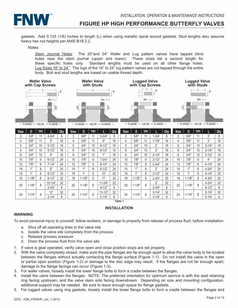
gaskets. Add 0.125 (1/8) inches to length (L) when using metallic spiral wound gaskets. Stud lengths also assume heavy hex nut heights per ANSI B18.2.2.
Notes:Stem Journal Holes: The 20”and 24” Wafer and Lug pattern valves have tapped blind holes near the stem journal (upper and lower). These sizes list a second length for these specific holes only. Standard lengths must be used on all other flange holes. Lug Sizes 16” to 24”: The lugs of the 16” to 24” lug pattern valves are not tapped through the entire body. Bolt and stud lengths are based on usable thread depth.
Wafer Valvewith Cap Screws
Wafer Valvewith Studs
Lugged Valvewith Cap Screws
Lugged Valvewith Studs
Size D TPI L Qty3 5/8" 11 4-3/4” 84 5/8" 11 5” 165 3/4" 10 5-1/2” 166 3/4" 10 5-1/2” 168 3/4" 10 6” 16
10 7/8" 9 6-1/2” 2412 7/8" 9 7-1/4” 2414 1" 8 8” 2416 1" 8 8-1/2” 3218 1-1/8" 8 9-1/2” 32
20 1-1/8" 8 10-1/4” 322-3/4” 8
24 1-1/4" 8 12” 323-1/4” 8
Size D TPI L Qty3 5/8" 11 5-3/4” 84 5/8" 11 6” 165 3/4" 10 6-1/2” 166 3/4" 10 6-1/2” 168 3/4" 10 7” 1610 7/8" 9 7-3/4” 2412 7/8" 9 8-1/4” 2414 1" 8 9-1/2” 2416 1" 8 10” 3218 1-1/8" 8 11” 32
20 1-1/8" 8 11-3/4” 324-1/2” 8
24 1-1/4" 8 13-1/2” 325-1/4” 8
Size D TPI L Qty3 5/8" 11 1-3/4” 84 5/8" 11 1-7/8” 165 3/4" 10 2” 166 3/4" 10 2” 168 3/4" 10 2-1/4” 1610 7/8" 9 2-1/2” 2412 7/8" 9 2-3/4” 2414 1" 8 3” 2416 1" 8 2-1/2” 3218 1-1/8" 8 2-3/4” 32
20 1-1/8" 8 3” 322-3/4” 8
24 1-1/4" 8 3-1/4” 323-1/4” 8
Size D TPI L Qty3 5/8" 11 3” 84 5/8" 11 3” 165 3/4" 10 3-1/4” 166 3/4" 10 3-1/4” 168 3/4" 10 3-1/2” 1610 7/8" 9 4” 2412 7/8" 9 4-1/4” 2414 1" 8 4-3/4” 2416 1" 8 4-1/4” 3218 1-1/8" 8 4-3/4” 32
20 1-1/8" 8 4-3/4” 324-1/2” 8
24 1-1/4" 8 5-1/4” 325-1/4” 8
INSTALLATIONWARNINGTo avoid personal injury to yourself, fellow workers, or damage to property from release of process fluid, before installation:
a. Shut off all operating lines to the valve siteb. Isolate the valve site completely from the processc. Release process pressured. Drain the process fluid from the valve site
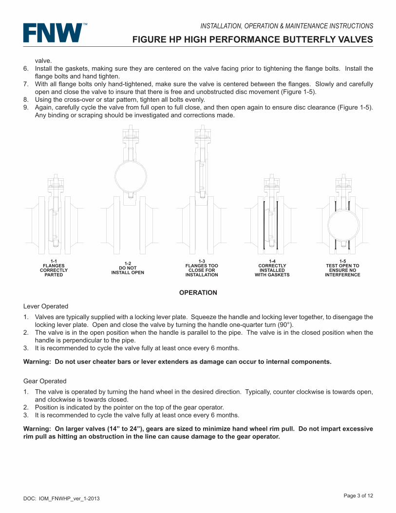
1. If valve is gear operated, verify valve open and close position stops are set properly2. With the valve completely closed, make sure the pipe flanges are far enough apart to allow the valve body to be located
between the flanges without actually contacting the flange surface (Figure 1-1). Do not install the valve in the open or partial open position (Figure 1-2) or damage to the disc edge may result. If the flanges are not far enough apart, damage to the flange facings can occur (Figure 1-3).
3. For wafer valves, loosely install the lower flange bolts to form a cradle between the flanges.4. Install the valve between the flanges. NOTE: The preferred orientation for optimum service is with the seat retaining
ring facing upstream, and the valve stem side facing downstream. Depending on size and mounting configuration, additional support may be needed. Be sure to leave enough space for flange gaskets.
5. For lugged valves using ring gaskets, loosely install the lower flange bolts to form a cradle between the flanges and
Table 1
DOC: IOM_FNWHP_ver_1-2013 Page 3 of 12
INSTALLATION, OPERATION & MAINTENANCE INSTRUCTIONS
FIGURE HP HIGH PERFORMANCE BUTTERFLY VALVES
valve.6. Install the gaskets, making sure they are centered on the valve facing prior to tightening the flange bolts. Install the
flange bolts and hand tighten.7. With all flange bolts only hand-tightened, make sure the valve is centered between the flanges. Slowly and carefully
open and close the valve to insure that there is free and unobstructed disc movement (Figure 1-5).8. Using the cross-over or star pattern, tighten all bolts evenly.9. Again, carefully cycle the valve from full open to full close, and then open again to ensure disc clearance (Figure 1-5).
Any binding or scraping should be investigated and corrections made.
1-1FLANGES
CORRECTLYPARTED
1-2DO NOTINSTALL
OPEN
1-3FLANGES TOCLOSE FOR
INSTALLATION
1-4CORRECTLY
INSTALLED WITHGASKETS
1-5TEST OPEN TO
ENSURE NOINTERFERENCE
1-1FLANGES
CORRECTLY PARTED
1-2DO NOT
INSTALL OPEN
1-3FLANGES TOO
CLOSE FOR INSTALLATION
1-4CORRECTLY INSTALLED
WITH GASKETS
1-5TEST OPEN TO
ENSURE NO INTERFERENCE
OPERATION
Lever Operated1. Valves are typically supplied with a locking lever plate. Squeeze the handle and locking lever together, to disengage the
locking lever plate. Open and close the valve by turning the handle one-quarter turn (90°).2. The valve is in the open position when the handle is parallel to the pipe. The valve is in the closed position when the
handle is perpendicular to the pipe.3. It is recommended to cycle the valve fully at least once every 6 months.
Warning: Do not user cheater bars or lever extenders as damage can occur to internal components.
Gear Operated1. The valve is operated by turning the hand wheel in the desired direction. Typically, counter clockwise is towards open,
and clockwise is towards closed.2. Position is indicated by the pointer on the top of the gear operator.3. It is recommended to cycle the valve fully at least once every 6 months.
Warning: On larger valves (14” to 24”), gears are sized to minimize hand wheel rim pull. Do not impart excessive rim pull as hitting an obstruction in the line can cause damage to the gear operator.
DOC: IOM_FNWHP_ver_1-2013 Page 4 of 12
INSTALLATION, OPERATION & MAINTENANCE INSTRUCTIONS
FIGURE HP HIGH PERFORMANCE BUTTERFLY VALVES
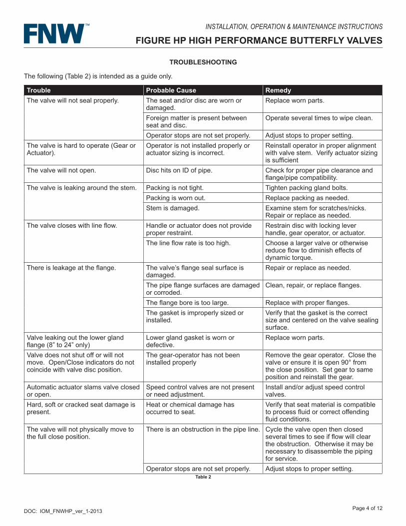
TROUBLESHOOTING
The following (Table 2) is intended as a guide only.
Trouble Probable Cause RemedyThe valve will not seal properly. The seat and/or disc are worn or
damaged.Replace worn parts.
Foreign matter is present between seat and disc.
Operate several times to wipe clean.
Operator stops are not set properly. Adjust stops to proper setting.The valve is hard to operate (Gear or Actuator).
Operator is not installed properly or actuator sizing is incorrect.
Reinstall operator in proper alignment with valve stem. Verify actuator sizing is sufficient
The valve will not open. Disc hits on ID of pipe. Check for proper pipe clearance and flange/pipe compatibility.
The valve is leaking around the stem. Packing is not tight. Tighten packing gland bolts.Packing is worn out. Replace packing as needed.Stem is damaged. Examine stem for scratches/nicks.
Repair or replace as needed.The valve closes with line flow. Handle or actuator does not provide
proper restraint.Restrain disc with locking lever handle, gear operator, or actuator.
The line flow rate is too high. Choose a larger valve or otherwise reduce flow to diminish effects of dynamic torque.
There is leakage at the flange. The valve’s flange seal surface is damaged.
Repair or replace as needed.
The pipe flange surfaces are damaged or corroded.
Clean, repair, or replace flanges.
The flange bore is too large. Replace with proper flanges.The gasket is improperly sized or installed.
Verify that the gasket is the correct size and centered on the valve sealing surface.
Valve leaking out the lower gland flange (8” to 24” only)
Lower gland gasket is worn or defective.
Replace worn parts.
Valve does not shut off or will not move. Open/Close indicators do not coincide with valve disc position.
The gear-operator has not been installed properly
Remove the gear operator. Close the valve or ensure it is open 90° from the close position. Set gear to same position and reinstall the gear.
Automatic actuator slams valve closed or open.
Speed control valves are not present or need adjustment.
Install and/or adjust speed control valves.
Hard, soft or cracked seat damage is present.
Heat or chemical damage has occurred to seat.
Verify that seat material is compatible to process fluid or correct offending fluid conditions.
The valve will not physically move to the full close position.
There is an obstruction in the pipe line. Cycle the valve open then closed several times to see if flow will clear the obstruction. Otherwise it may be necessary to disassemble the piping for service.
Operator stops are not set properly. Adjust stops to proper setting.Table 2
DOC: IOM_FNWHP_ver_1-2013 Page 5 of 12
INSTALLATION, OPERATION & MAINTENANCE INSTRUCTIONS
FIGURE HP HIGH PERFORMANCE BUTTERFLY VALVES
MAINTENANCEUnder normal operating conditions, these valves do not require maintenance or lubrication. It is recommended to cycle the valve fully at least once every 6 months. However, valve parts are subject to normal wear and should be inspected and replaced as necessary. Inspection and maintenance frequency depends on the severity of the service conditions. This section includes assembly and disassembly instructions.
WARNINGTo avoid personal injury to yourself, fellow workers, or damage to property, prior to any maintenance, verify the following conditions.
a. Be sure the line is depressurized and drained.b. Be sure of the pipe line media. Proper care should be taken for protection against toxic and/or flammable fluids.c. Never remove the operator from the valve while the valve is in the pipeline under pressure.d. Always be sure the disc is in the closed position before removing the valve.
GeneralThe following periodic preventative maintenance practices are recommended for all high performance style butterfly valves.
i. Operate the valve from full open to full close to assure operability.ii. Check flange bolting for evidence of loosening and correct as needed.iii. Inspect the valve and surrounding area for previous or existing leakage at flange faces or stem.iv. Check piping and/or wiring to actuator and related equipment for looseness and correct as needed.
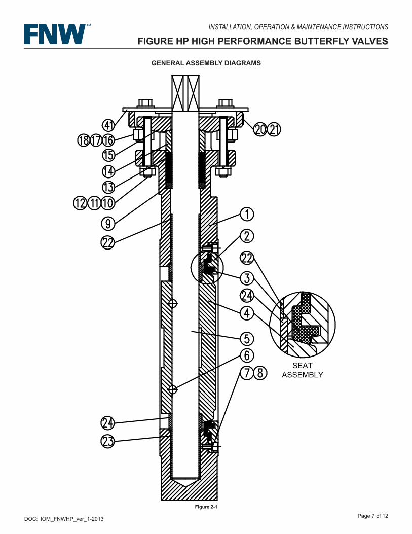
High Performance Butterfly Valve Disassembly and AssemblyDISASSEMBLY - The following are disassembly instructions for the figure HP high performance style butterfly valves. General assembly diagrams are provided at the end of this section (Figure 2-1 to 2-3). These steps pertain to the replacement of soft goods parts (i.e. - seat and packing). Components such as stems, bearings, and disc require separation of welded components and is not recommended. Materials and number of parts can vary by size and configuration. Refer to the Bill of Materials table (Table 4) for details. Make sure a clean area is available to work in and to place disassembled parts. Parts should be protected from dirt, dust, and possible damage. Follow applicable safety practices when removing the valve from service.1. With the valve slightly open, remove the seat retainer ring (2) by loosening and removing the retainer ring bolts (8) and
washers (7).2. Remove the seat (3). The seat may be in the valve body (1) or on the seat retaining ring (2). 3. Remove the lever handle or gear (Note or mark the original operator positions for future reassembly).
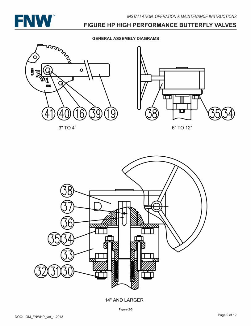
A. Lever - Remove lever retaining bolt (40) and bolt washer (39). Squeeze the lever lock and lift the lever (19) straight up off the stem (5). Loosen and remove the lever lock plate bolt (16) , nut (17) , and washer (18). Lift the lever lock plate (41) up off the stem (5).
B. Gear - Loosen and remove the gear mounting bolts (34) and washers (35). With proper support, lift the gear operator (38) straight up off the stem (5). For 14” to 24” valves, there is also a mounting bracket (33). Remove the mounting bracket by first loosening and removing the mounting pad bolts (32), nuts (30), and washers (31). Lift the bracket (33) up off the stem (5).
For other actuators, consult the device’s manual.4. For 14” to 24” valves, remove the stem keys (36) with pins (37) from the stem (5).5. Remove the packing gland flange (15) and gland ring (14) by first loosening and removing the gland nut (11) and washer
(12) from the packing gland studs (10). For sizes 12” and smaller, the packing gland flange with attached gland studs can be lifted up off the stem (5).
6. For sizes 14” to 24”, the packing gland flange (15) can be lifted off the gland studs (10) and stem (5). If they are not welded in place, the gland studs can be unthreaded from the valve body (1).
7. Lift the packing gland ring (14) up off the stem (5).8. With appropriate tools, remove the layers of chevron packing (13) from the packing well. Care should be taken not to
scratch the interior wall of the well or the stem (5)9. Remove the packing spacer (9) from the packing well by hooking it with wire and pulling up, or by turning the valve
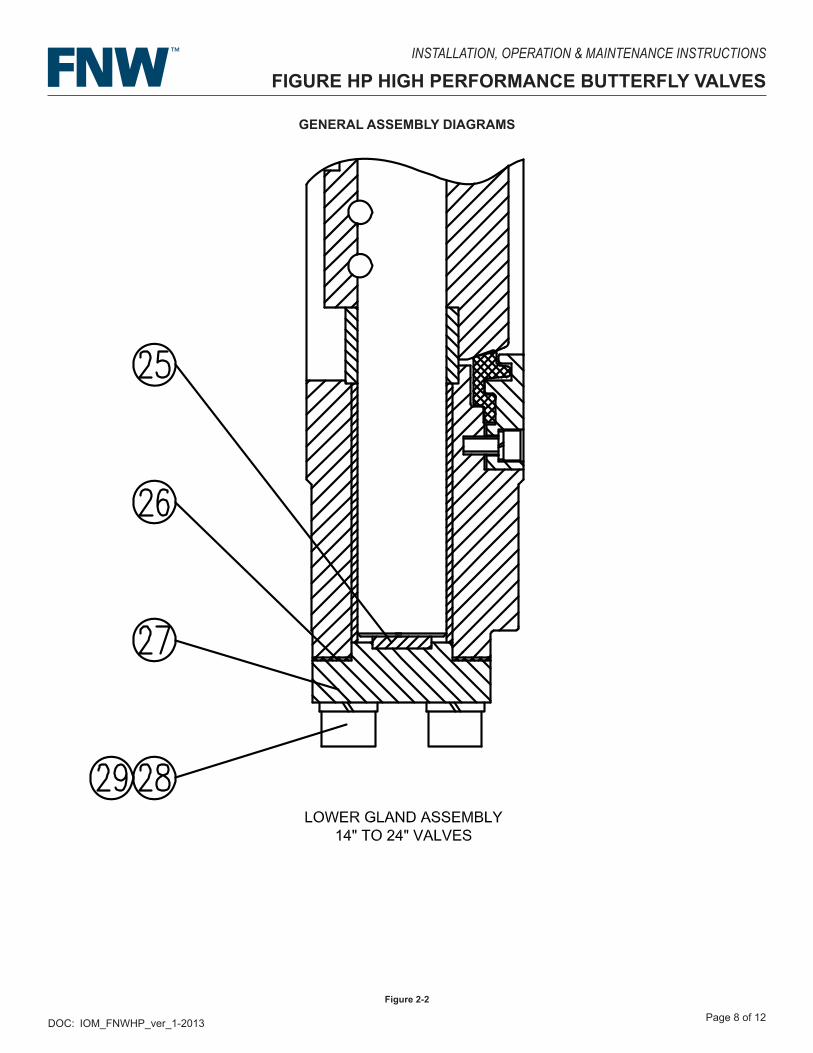
upside down.10. For 8” to 24” valves, remove the lower gland flange (27) by loosing and removing the flange bolts (28) and washers (29).
Remove the lower gland gasket (28) and disc spring (25)(14” to 24” valves only).
DOC: IOM_FNWHP_ver_1-2013 Page 6 of 12
INSTALLATION, OPERATION & MAINTENANCE INSTRUCTIONS
FIGURE HP HIGH PERFORMANCE BUTTERFLY VALVES
ASSEMBLY - The following are assembly instructions for the figure HP high performance style butterfly valves. General assembly diagrams are provided at the end of this section (Figure 2-1 to 2-3). These steps pertain to the replacement of soft goods parts (i.e. - seat and packing). Components such as stems, bearings, and disc require welding of components and is not recommended. Materials and number of parts can vary by size and configuration. Refer to the Bill of Materials table (Table 4) for details. Make sure that all components are present and undamaged prior to assembly. Make sure a clean area is available to work in. Parts should be protected from dirt, dust, and possible damage.1. Install the packing spacer (9) over the stem (5) and push it down to the bottom of the packing well in the body (1). Care
should be taken not to scratch the well interior or the stem.2. Install chevron packing (13). 3. If they are not welded in place, the gland studs (10) can be threaded into the valve body (1).4. Lower the packing gland ring (14) over the stem (5), followed by the packing gland flange (15). For 12” and smaller
valves, the gland flange and welded gland studs should align with the holes in the top of the valve body (1). For 14” to 24” valves, the gland flange should align with the gland studs in the body.
5. Press down on the packing gland flange (15) to push the packing (13) down. If the packing is more than one row below the top of the packing well, then add another row of packing. The packing should not be higher than the packing well.
6. Install the packing gland washers (12) and nuts (11) evenly to hand tight. With a wrench, tighten the nuts at least one and a half more turns. Note: Additional packing adjustments may be needed when the valve is recommissioned.
7. Install the stem keys (36) with pins (37) onto the stem by aligning the pins to the holes in the stem keyways. It may be necessary to tap the keys on with a hammer. Tap lightly over the pin holes in the keys making sure the pins are started in their stem holes and the key is aligned with the keyway.
8. With the valve partial open, install the seat (3) into the seat groove of the body (1). The seat has an asymmetrical multi-faceted shape and can only be installed one way. Press firmly to ensure the seat is solidly resting in its groove.
9. Align the bolt holes of the seat retaining ring (2) to those on the body (1) and push the retaining ring onto the seat (3) / body (1) assembly making sure the grooves of seat and retainer are aligned properly. If the bolt holes of the retainer ring do not align properly with the holes in the body, attempt to align them by spinning the retainer ring. If friction prevents this, then remove the ring and reinstall.
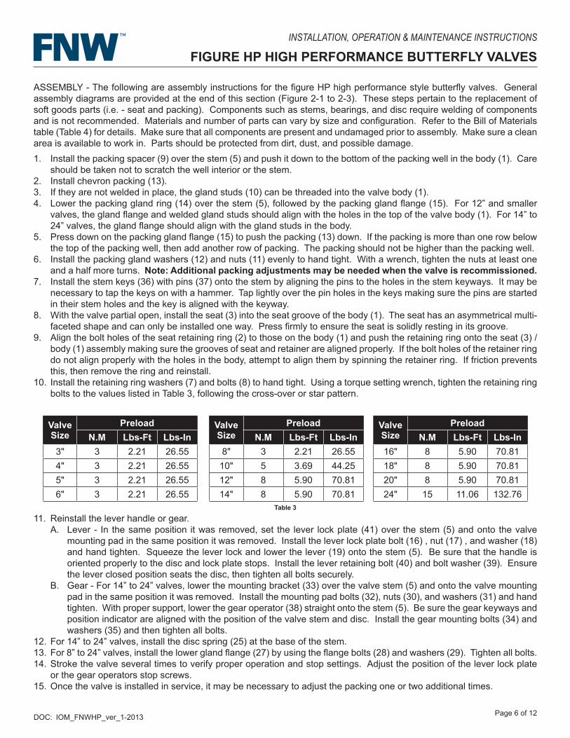
10. Install the retaining ring washers (7) and bolts (8) to hand tight. Using a torque setting wrench, tighten the retaining ring bolts to the values listed in Table 3, following the cross-over or star pattern.
11. Reinstall the lever handle or gear.A. Lever - In the same position it was removed, set the lever lock plate (41) over the stem (5) and onto the valve
mounting pad in the same position it was removed. Install the lever lock plate bolt (16) , nut (17) , and washer (18) and hand tighten. Squeeze the lever lock and lower the lever (19) onto the stem (5). Be sure that the handle is oriented properly to the disc and lock plate stops. Install the lever retaining bolt (40) and bolt washer (39). Ensure the lever closed position seats the disc, then tighten all bolts securely.
B. Gear - For 14” to 24” valves, lower the mounting bracket (33) over the valve stem (5) and onto the valve mounting pad in the same position it was removed. Install the mounting pad bolts (32), nuts (30), and washers (31) and hand tighten. With proper support, lower the gear operator (38) straight onto the stem (5). Be sure the gear keyways and position indicator are aligned with the position of the valve stem and disc. Install the gear mounting bolts (34) and washers (35) and then tighten all bolts.
12. For 14” to 24” valves, install the disc spring (25) at the base of the stem.13. For 8” to 24” valves, install the lower gland flange (27) by using the flange bolts (28) and washers (29). Tighten all bolts.14. Stroke the valve several times to verify proper operation and stop settings. Adjust the position of the lever lock plate
or the gear operators stop screws.15. Once the valve is installed in service, it may be necessary to adjust the packing one or two additional times.
Valve Size
Preload Valve Size
Preload Valve Size
PreloadN.M Lbs-Ft Lbs-In N.M Lbs-Ft Lbs-In N.M Lbs-Ft Lbs-In
3" 3 2.21 26.55 8" 3 2.21 26.55 16" 8 5.90 70.814" 3 2.21 26.55 10" 5 3.69 44.25 18" 8 5.90 70.815" 3 2.21 26.55 12" 8 5.90 70.81 20" 8 5.90 70.816" 3 2.21 26.55 14" 8 5.90 70.81 24" 15 11.06 132.76
Table 3
DOC: IOM_FNWHP_ver_1-2013 Page 7 of 12
INSTALLATION, OPERATION & MAINTENANCE INSTRUCTIONS
FIGURE HP HIGH PERFORMANCE BUTTERFLY VALVES
GENERAL ASSEMBLY DIAGRAMS
Figure 2-1
DOC: IOM_FNWHP_ver_1-2013 Page 8 of 12
INSTALLATION, OPERATION & MAINTENANCE INSTRUCTIONS
FIGURE HP HIGH PERFORMANCE BUTTERFLY VALVES
Figure 2-2
GENERAL ASSEMBLY DIAGRAMS
DOC: IOM_FNWHP_ver_1-2013 Page 9 of 12
INSTALLATION, OPERATION & MAINTENANCE INSTRUCTIONS
FIGURE HP HIGH PERFORMANCE BUTTERFLY VALVES
GENERAL ASSEMBLY DIAGRAMS
Figure 2-3
DOC: IOM_FNWHP_ver_1-2013 Page 10 of 12
INSTALLATION, OPERATION & MAINTENANCE INSTRUCTIONS
FIGURE HP HIGH PERFORMANCE BUTTERFLY VALVES
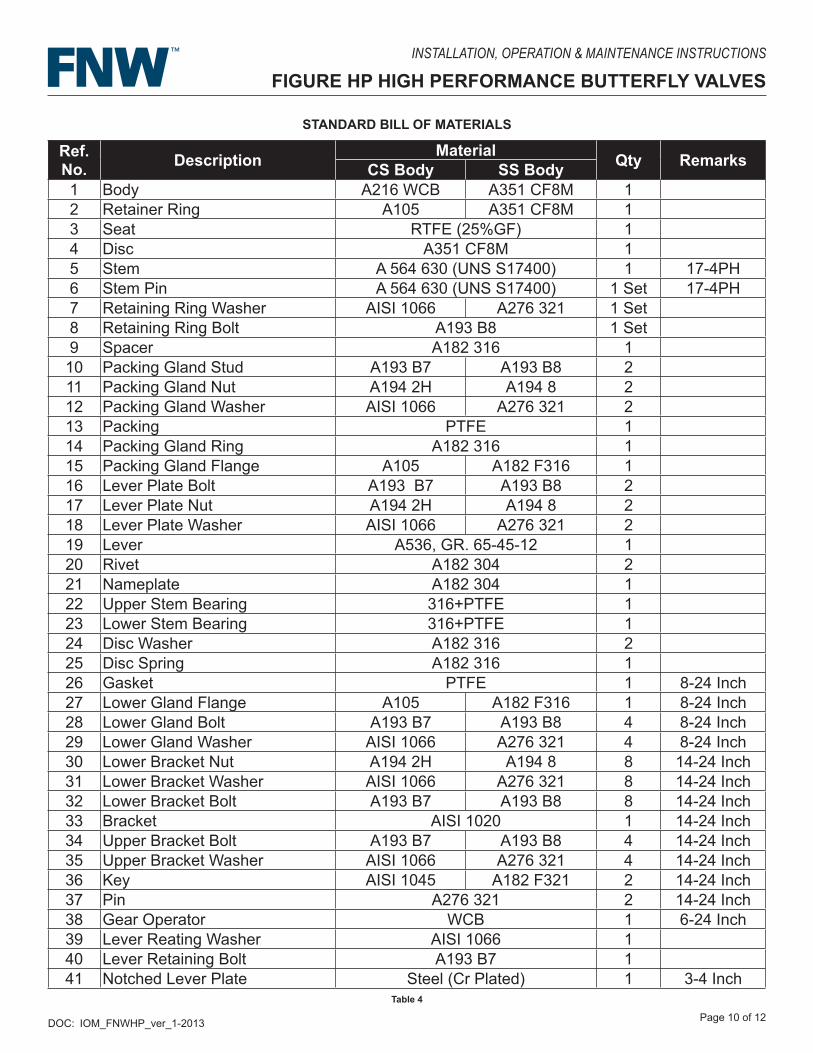
STANDARD BILL OF MATERIALS
Table 4
Ref. No. Description Material Qty RemarksCS Body SS Body1 Body A216 WCB A351 CF8M 12 Retainer Ring A105 A351 CF8M 13 Seat RTFE (25%GF) 14 Disc A351 CF8M 15 Stem A 564 630 (UNS S17400) 1 17-4PH6 Stem Pin A 564 630 (UNS S17400) 1 Set 17-4PH7 Retaining Ring Washer AISI 1066 A276 321 1 Set8 Retaining Ring Bolt A193 B8 1 Set9 Spacer A182 316 110 Packing Gland Stud A193 B7 A193 B8 211 Packing Gland Nut A194 2H A194 8 212 Packing Gland Washer AISI 1066 A276 321 213 Packing PTFE 114 Packing Gland Ring A182 316 115 Packing Gland Flange A105 A182 F316 116 Lever Plate Bolt A193 B7 A193 B8 217 Lever Plate Nut A194 2H A194 8 218 Lever Plate Washer AISI 1066 A276 321 219 Lever A536, GR. 65-45-12 120 Rivet A182 304 221 Nameplate A182 304 122 Upper Stem Bearing 316+PTFE 123 Lower Stem Bearing 316+PTFE 124 Disc Washer A182 316 225 Disc Spring A182 316 126 Gasket PTFE 1 8-24 Inch27 Lower Gland Flange A105 A182 F316 1 8-24 Inch28 Lower Gland Bolt A193 B7 A193 B8 4 8-24 Inch29 Lower Gland Washer AISI 1066 A276 321 4 8-24 Inch30 Lower Bracket Nut A194 2H A194 8 8 14-24 Inch31 Lower Bracket Washer AISI 1066 A276 321 8 14-24 Inch32 Lower Bracket Bolt A193 B7 A193 B8 8 14-24 Inch33 Bracket AISI 1020 1 14-24 Inch34 Upper Bracket Bolt A193 B7 A193 B8 4 14-24 Inch35 Upper Bracket Washer AISI 1066 A276 321 4 14-24 Inch36 Key AISI 1045 A182 F321 2 14-24 Inch37 Pin A276 321 2 14-24 Inch38 Gear Operator WCB 1 6-24 Inch39 Lever Reating Washer AISI 1066 140 Lever Retaining Bolt A193 B7 141 Notched Lever Plate Steel (Cr Plated) 1 3-4 Inch
DOC: IOM_FNWHP_ver_1-2013 Page 11 of 12
INSTALLATION, OPERATION & MAINTENANCE INSTRUCTIONS
FIGURE HP HIGH PERFORMANCE BUTTERFLY VALVES
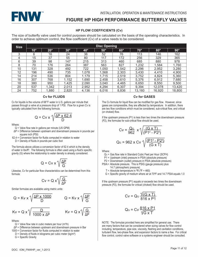
HP FLOW COEFFICIENTS (Cv)
Size Disc Opening10° 20° 30° 40° 50° 60° 70° 80° 90°
3 6 16 24 36 52 76 113 146 1624 15 37 55 80 117 172 256 329 3656 39 98 147 215 313 460 685 880 9788 70 176 264 387 563 827 1,232 1,584 1,760
10 131 328 492 722 1,050 1,542 2,296 2,952 3,28012 196 490 735 1,078 1,568 2,303 3,430 4,410 4,90014 214 536 804 1,179 1,715 2,519 3,752 4,824 5,36016 307 768 1,152 1,690 2,458 3,610 5,376 6,912 7,68018 380 950 1,425 2,090 3,040 4,465 6,650 8,550 9,50020 537 1,342 2,013 2,952 4,294 6,307 9,394 12,078 13,42024 752 1,880 2,820 4,136 6,016 8,836 13,160 16,920 18,800
Cv for FLUIDSCv for liquids is the volume of 68°F water in U.S. gallons per minute that passes through a valve at a pressure drop of 1 PSI. Flow for a given Cv is typically calculated from the following formula.
Where: Q = Valve flow rate in gallons per minute (US GPM) ΔP = Difference between upstream and downstream pressure in pounds per square inch (PSI) 62.4 = Conversion factor for fluids computed in relation to water D = Density of fluids in pounds per cubic foot
Q = Cv x ΔP x 62.4 D
The formula above utilizes a conversion factor of 62.4 which is the density of water in lbs/ft³. The following formula is often used using a fluid’s specific gravity (G) where the relationship to water density is already considered.
Q = Cv x ΔP G
Likewise, Cv for particular flow characteristics can be determined from this formula:
Cv = Q x G ΔP
Kv = Q x D 1000 x ΔP
Similar formulas are available using metric units:
Q = Kv x ΔP x 1000 D
Q = Kv x ΔP G
Kv = Q x G ΔP
Where: Q = Valve flow rate in cubic meters per hour (m³/h) ΔP = Difference between upstream and downstream pressure in Bar 1000 = Conversion factor for fluids computed in relation to water D = Density of fluids in kilograms per cubic meter (kg/m³) G = Specific Gravity
Cv for GASESThe Cv formula for liquid flow can be modified for gas flow. However, since gases are compressible, they are affected by temperature. In addition, there are two flow conditions which must be considered, sub-critical flow, and critical (or choked) flow.
If the upstream pressure (P1) is less than two times the downstream pressure (P2), the formulas for sub-critical flow should be used.
Cv = QG x (G x T) 962 (P1² - P2²)
QG = 962 x Cv (P1² - P2²) (G x T)
Where: QG = Gas flow rate in Standard Cubic Feet per Hour (SCFH) P1 = Upstream (inlet) pressure in PSIA (absolute pressure) P2 = Downstream (outlet) pressure in PSIA (absolute pressure) PSIA = Absolute pressure. This is PSIG (gauge pressure) plus 14.7 (atmospheric pressure) T = Absolute temperature in ºR (ºF + 460) G = Specific gravity of medium where air at 70ºF and 14.7 PSIA equals 1.0
If the upstream pressure (P1) equals or exceeds two times the downstream pressure (P2), the formulas for critical (choked) flow should be used.
Cv = QG (G x T)
816 x P1
QG = Cv 816 x P1 G x T
NOTE: The formulas provided here are simplified for general use. There are many factors that can be considered when sizing valves for flow control including, temperature, pipe size, viscosity, flashing and cavitation conditions, turbulent flow, two-phase flow, and expansion factors to name a few. For critical flow control, control valve software or a systems engineer should be consulted.
The size of butterfly valve used for control purposes should be calculated on the basis of the operating characteristics. In order to achieve optimum control, the flow coefficient (Cv) of a valve needs to be considered.
DOC: IOM_FNWHP_ver_1-2013 Page 12 of 12
INSTALLATION, OPERATION & MAINTENANCE INSTRUCTIONS
FIGURE HP HIGH PERFORMANCE BUTTERFLY VALVES
WARRANTY
1. LIMITED WARRANTY: Subject to the limitations expressed herein, Seller warrants that products manufactured by Seller shall be free from defects in design, material and workmanship under normal use for a period of one (1) year from installation but in no case shall the warranty period extend longer than eighteen months from the date of sale. This warranty is void for any damage caused by misuse, abuse, neglect, acts of God, or improper installation. For the purpose of this section, “Normal Use” means in strict accordance with the installation, operation and maintenance manual. The warranty for all other products is provided by the original equipment manufacturer.
2. REMEDIES: Seller shall repair or replace, at its option, any non-conforming or otherwise defective product, upon receipt of notice from Buyer during the Manufacturer’s warranty period at no additional charge. SELLER HEREBY DISCLAIMS ALL OTHER EXPRESSED OR IMPLIED WARRANTIES, INCLUDING, WITHOUT LIMITATION, ALL IMPLIED WARRANTIES OF MERCHANTABILITY AND FITNESS OR FITNESS FOR A PARTICULAR PURPOSE.
3. LIMITATION OF LIABILITY: UNDER NO CIRCUMSTANCES SHALL EITHER PARTY BE LIABLE TO THE OTHER FOR INCIDENTAL, PUNITIVE, SPECIAL OR CONSEQUENTIAL DAMAGES OF ANY KIND. BUYER HEREBY ACKNOWLEDGES AND AGREES THAT UNDER NO CIRCUMSTANCES, AND IN NO EVENT, SHALL SELLER’S LIABILITY, IF ANY, EXCEED THE NET SALES PRICE OF THE DEFECTIVE PRODUCT(S) PURCHASED DURING THE PREVIOUS CONTRACT YEAR.
4. LABOR ALLOWANCE: Seller makes NO ADDITIONAL ALLOWANCE FOR THE LABOR OR EXPENSE OF REPAIRING OR REPLACING DEFECTIVE PRODUCTS OR WORKMANSHIP OR DAMAGE RESULTING FROM THE SAME.
5. RECOMMENDATIONS BY SELLER: Seller may assist Buyer in selection decisions by providing information regarding products that it manufacturers and those manufactured by others. However, Buyer acknowledges that Buyer ultimately chooses the product’s suitability for its particular use, as normally signified by the signature of Buyer’s technical representative. Any recommendations made by Seller concerning the use, design, application or operation of the products shall not be construed as representations or warranties, expressed or implied. Failure by Seller to make recommendations or give advice to Buyer shall not impose any liability upon Seller.
6. EXCUSED PERFORMANCE: Seller will make a good faith effort to complete delivery of the products as indicated by Seller in writing, but Seller assumes no responsibility or liability and will accept no back-charge for loss or damage due to delay or inability to deliver, caused by acts of God, war, labor difficulties, accidents, inability to obtain materials, delays of carriers, contractors or suppliers or any other causes of any kind whatever beyond the control of Seller. Under no circumstances shall Seller be liable for any special, consequential, incidental, or indirect damages, losses, or expense (whether or not based on negligence) arising directly or indirectly from delays or failure to give notice of delay.