FLUID MECHANICS - Amazon Web Services...Topics Page No 1. BASICS OF FLUID MECHANICS 1.1 Definition...
33
FLUID MECHANICS For MECHANICAL ENGINEERING CIVIL ENGINEERING
Transcript of FLUID MECHANICS - Amazon Web Services...Topics Page No 1. BASICS OF FLUID MECHANICS 1.1 Definition...

FLUID MECHANICS
For MECHANICAL ENGINEERING
CIVIL ENGINEERING


SYLLABUS Fluid properties; fluid statics, manometry, buoyancy, forces on submerged bodies, stability of floating bodies; control-volume analysis of mass, momentum and energy; fluid acceleration; differential equations of continuity and momentum; Bernoulli’s equation; dimensional analysis; viscous flow of incompressible fluids, boundary layer, elementary turbulent flow, flow through pipes, head losses in pipes, bends and fittings. Turbomachinery: Impulse and reaction principles, velocity diagrams, Pelton-wheel, Francis and Kaplan turbines.
ANALYSIS OF GATE PAPERS MECHANICAL
Exam Year
1 Mark Ques.
2 Mark Ques. Total
2003 1 6 13 2004 2 9 20 2005 1 3 7 2006 3 7 17 2007 3 7 17 2008 1 5 11 2009 - 7 14 2010 4 3 10 2011 1 3 7 2012 3 2 7 2013 2 2 6
2014 Set-1 1 5 11 2014 Set-2 2 3 8 2014 Set-3 3 3 9 2014 Set-4 2 2 6 2015 Set-1 1 4 9 2015 Set-2 2 2 6 2015 Set-3 2 2 6 2016 Set-1 3 3 9 2016 Set-2 2 3 8 2016 Set-3 3 3 9 2017 Set-1 4 3 10 2017 Set-2 4 3 10
CIVIL Exam Year
1 Mark Ques.
2 Mark Ques. Total
2003 3 8 19 2004 6 10 26 2005 3 7 17 2006 3 7 17 2007 2 7 16 2008 1 7 15 2009 1 3 7 2010 3 2 7 2011 3 2 7 2012 3 3 2013 3 2 7
2014 Set-1 2 7 16 2014 Set-2 2 4 10 2015 Set-1 3 4 11 2015 Set-2 3 3 9 2016 Set-1 1 3 7 2016 Set-2 1 3 7 2017 Set-1 2 3 8
FLUID MECHANICS
2018 Set-1 2 3 8 2018 Set-2 3 4 11
2017 Set-2 1 2 5
2018 Set-1 2 3 8
2018 Set-2 1 2 5

Topics Page No
1. BASICS OF FLUID MECHANICS
1.1 Definition of Fluid 01 1.2 Basic Equations 01 1.3 System and Control Volume 01
2. PROPERTIES OF FLUIDS
2.1 Density 02 2.2 Specific Gravity/Relative Density 02 2.3 Viscosity 02 2.4 Surface Tension 05 2.5 Capillarity 06 2.6 Thermo Dynamic Properties 07 2.7 Compressibility and Bulk Modulus 07 2.8 Vapor Pressure 08 2.9 Cavitations 08
3. PRESSURE & FLUID STATICS
3.1 Pressure 09 3.2 The Barometer and Atmospheric Pressure 10 3.3 Principles of Fluid Statics 10 3.4 Pressure Measurement 11 3.5 Hydrostatic Forces on Surfaces 18 3.6 Buoyancy & Floatation 30
4. KINEMATICS
4.1 Introduction 37 4.2 Methods of Describing Fluid Motion 37 4.3 Types of Fluid Flow 37 4.4 Continuity Equation in Three-Dimensions 39 4.5 Continuity Equation in One Dimension 39 4.6 Motion of Fluid Element 40 4.7 Flow Patterns 41 4.8 Stream Function 42 4.9 Velocity Potential Function 42 4.10 Equipotential Line 42
5. BERNOULLI’S EQUATION & ITS APPLICATIONS
5.1 Introduction 48
CONTENTS

5.2 Euler’s Equation 48 5.3 Bernoulli’s Equation 48 5.4 Application Of Bernoulli’s Equation 49 5.5 Bernoulli’s Equation For Real Fluids 51 5.6 Free Liquid Jets 51
6. FLOW THROUGH CONDUITS/PIPES
6.1 Internal Flow 56 6.2 Laminar Flow/Viscous Flow 56 6.3 Turbulent Flow in Pipes 57 6.4 Loss of Energy in Fluid Flow 60 6.5 Flow through Pipes in Series or Flow through Compound Pipes 62 6.6 Flows through Nozzles 62
7. EXTERNAL FLOW
7.1 Boundary Layer Formation 71 7.2 Regions of Boundary Layer 71 7.3 Boundary Layer Thickness 71 7.4 Drag Force on a Flat Plate Due To Boundary Layer 72 7.5 Boundary Condition for the Velocity Profile 72 7.6 Analysis of Turbulent Boundary Layer 73 7.7 Boundary Layer Separation 74
8. DYNAMICS OF FLUID FLOW
8.1 Introduction 79 8.2 Impulse Momentum Principle 79 8.3 Force Exerted By a Fluid on a Pipe Bend 79 8.4 Force Exerted By a Fluid on Vertical Stationary Plate 79 8.5 Force Exerted By a Fluid on Moving Blade 80
9. HYDRAULLIC TURBINES
9.1 Introduction 87 9.2 Classification of Turbines 87 9.3 Turbine Efficiencies 87 9.4 Power Developed by Turbine (Euler’s Equation) 88 9.5 Pelton Turbine 88 9.6 Reaction Turbine 89 9.7 Francis Turbine 91 9.8 Kaplan Turbine 91 9.9 Specific Speed Significance 91 9.10 Model Testing (Dimensionless Turbine Parameters) 92
10. GATE QUESTIONS 99
11. ASSIGNMENT QUESTIONS 195

3.1 PRESSURE
Pressure is defined as the normal force exerted by fluid per unit area. We speak of pressure only when we deal with a gas or a liquid. The counterpart of pressure in solids is normal stress.
FPA
=
Since pressure is defined as force per unit area, it has the unit of Newtons per square meter (N/m2), which is called Pascal (Pa) 1bar = 105 Pa = 0.1 MPa = 100 kPa 3.1.1 ABSOLUTE, GAUGE, ATMOSPHERIC & VACUUM PRESSURE
1) The pressure values must be statedwith respect to a reference level. If thereference level is vacuum (i.e. absolutezero pressure), pressures are termedabsolute pressure.
2) Most pressure gauges indicate apressure difference—the differencebetween the measured pressure and theambient level (usually atmosphericpressure). Pressure levels measuredwith respect to atmospheric pressureare termed gauge pressures
3) Pressures below atmospheric pressureare called vacuum pressures.Absolute, gauge, and vacuum pressuresare all positive quantities and arerelated to each other by
absolute atmospheric gaugeP P P= +
vacuum atmospheric absoluteP P P= +
3.1.2 PRESSURE AT A POINT
Pressure is the compressive force per unit area, and it gives the impression of being a vector. However, in fluids under static conditions, pressure is found to be independent of the orientation of the area. This concept is explained by Pascal’s law which states that the pressure at a point in a fluid at rest is equal in magnitude in all directions. Pressure has magnitude but not a specific direction, and thus it is a scalar quantity.
x y zP P P= =
3.1.3 PRESSURE VARIATION IN A STATIC FLUID (HYDROSTATIC LAW):
For fluids at rest or moving on a straight path at constant velocity, all components of acceleration are zero. In fluids at rest, the pressure remains constant in any horizontal direction (P is independent of x and y) and varies only in the vertical direction. As a result of gravity, these relations are applicable for both compressible and incompressible fluids. dp dp dp(g), 0, 0dz dx dy
= −ρ = =
The negative sign is taken because dz is taken positive in upward direction and pressure decrease in upward direction. For incompressible fluid ρ is constant.
o o
p z
p z
dp g dz= −ρ∫ ∫
o oP P g(z z )− = −ρ −
oP P gh− = ρ For compressible fluid, ρ varies with pressure, i.e. f (P)ρ =For gases, variation of density with pressure can be expressed by ideal gas equation
3 PRESSURE & FLUID STATICS
© Copyright Reserved by Inspiring Creativity & Enedavour Gate Institute No part of this material should be copied or reproduced without permission 9

PRT
ρ =
Where , P is pressure T is temperature
3.1.4 FLUIDS IN RIGID-BODY MOTION
When fluid is in stationary container, the pressure remains constant along horizontal direction. The pressure varies only along vertical direction. When a fluid is placed in an accelerated container, initially fluid splashes and there is a relative motion between fluid & container boundary. After some time, the liquid comes to rest and attains fixed shape relative to container. The pressure varies in the direction of acceleration. 1) When container accelerates in
vertical directionCase1: Downward acceleration of az
( )zdp dp dpg a , 0, 0dz dx dy
= −ρ − = =
Case 2: upward acceleration of az
( )zdp dp dpg a , 0, 0dz dx dy
= −ρ + = =
2) When container accelerates inhorizontal directionCase1: Acceleration in positive xdirection
( ) xdp dp dp= -ρ g , = -ρa , =0dz dx dy
Case 2: Acceleration in negative xdirection
( ) ( )xdp dp dpg , a , 0dz dx dy
= −ρ = −ρ − =
3.2 THE BAROMETER & ATMOSPHERIC
PRESSURE Atmospheric pressure is measured by a device called barometer; thus, the atmospheric pressure is often referred to as the barometric pressure. The pressure at point B is equal to the atmospheric pressure, and the pressure at C can be taken to be zero since there is only mercury
vapour above point C and the pressure is very low relative to atmP and can be neglected for an excellent approximation. Writing a force balance in the vertical direction gives
atmP gh= ρWhere, ρ is the density of mercury, g is the local gravitational acceleration, h is the height of the mercury column above the free surface. Note that the length and the cross-sectional area of the tube have no effect on the height of the fluid column of a barometer. A frequently used pressure unit is the standard atmosphere, which is defined as the pressure produced by a column of mercury 760 mm in height at 0°C( )3
Hg is13,595kg / mρ . If water instead of mercury were used to measure the standard atmospheric pressure, a water column of about 10.3m would be needed.
3.3 PRINCIPLES OF FLUID STATICS
1) When fluid is at rest, in a continuousfluid, fluid at the same elevation has thesame pressure.
2) The pressure at the bottom of a columnof fluid is equal to the pressure at thetop, plus density multiplied by gravitymultiplied by the height of the column offluid.A consequence of the second principleis that when different columns of fluidstack on top of one another, thepressures due to each column simplyadd up.
© Copyright Reserved by Inspiring Creativity & Enedavour Gate Institute No part of this material should be copied or reproduced without permission
Pressure & Fluid Statics
10

3.3.1 HYDRAULIC LIFT A consequence of the pressure in a fluid remaining constant in the horizontal direction is that the pressure applied to a confined fluid increases the pressure throughout by the same amount. This is called Pascal’s law. The application of Pascal’s law in hydraulic lift is shown in fig P1= P2
1 1 2 2F / A F / A=
Fig.: Schematic of a hydraulic lift
3.4 PRESSURE MEASUREMENT
Hydrostatic law indicates the pressure difference b/w two points in a static fluid. A device based on this principle is called manometer, and it is commonly used to measure small and moderate pressure differences. A manometer mainly consists of a glass or plastic U tube containing one or more fluids such as mercury, water, alcohol, or oil. The pressure of a fluid is measured by the following. 1) Manometers
a. Simple• Piezometer• U-tube manometer• Single column manometerb. Differential• U-tube differential manometer• Inverted U-tube manometer
2) Mechanical gauge
3.4.1 SIMPLE MANOMETER
1) Piezometer: It is the simplest kind ofmanometer. It does not have any highdensity liquid. The tube is connected tothe point where pressure is to bemeasured. The liquid rises in tube tobalance the pressure at ‘A’.The gauge pressure PA is given by AP gh= ρWhere ρ is the density of liquid inside vessel/pipe
Piezometer is used to measure low pressures. The height of column increases if pressure is high. E.g. height of water column is 10.3 m if gauge pressure at ‘A’ is 1atm (105N/m2).
2) U-tube manometer: It has a glass U- tube with liquid having density higherthan the density of fluid in thecontainer.
The atmospheric pressure exists and should be taken into account for evaluation of absolute pressure, but while evaluating gauge pressure it is not accounted in equations. The gauge pressure at ‘A’ is given by
1 A c 1P P gh= +ρ
2 m 2P gh= ρWhere,
© Copyright Reserved by Inspiring Creativity & Enedavour Gate Institute No part of this material should be copied or reproduced without permission
Pressure & Fluid Statics
11

Cρ is the density of fluid in container, it can be water or oil
mρ is the density of manometric fluid. Usually mercury is chosen as manometric fluid
2h is difference in mercury level
AP is pressure in vessel/pipe in gauge From principle of fluid statics, when fluid is at rest, fluid at the same elevation has the same pressure.
A m 2 w 1P gh gh= ρ −ρ
3) Single Column Manometers: In thismanometer a large cross-sectional areareservoir is placed in one of the limbs.When pressure is applied, the fluidlowers slightly in the reservoir ascompared to the fluid rise in the otherlimb.
Gauge Pressure at point A is given as
( ) ( )2A m c m 2 c 1
ahP . g g gh ghA
= ρ −ρ + ρ −ρ
Since A>>α
A m 2 c 1P gh gh= ρ −ρ
Salient features of Single column manometer: i) modified form of U-tube manometerii) large cross-sectional area (100
times)iii) due to large area of cross section
and small change of pressure, thechange in level of reservoir will bevery small and can be neglected.
4) Inclined Single Column Manometer:This manometer is more sensitive than
straight column. The liquid rises more in the column due to inclination.
2h Lsin= θ
( ) ( )2A 2 1 2 2 1 1
ahP . g g gh ghA
= ρ −ρ + ρ −ρ
A 2 2 2 1 1 1P g h g h= ρ −ρ
A 2 2 1 1P g Lsin gh= ρ θ−ρ
3.4.2 DIFFERENTIAL MANOMETERS
Differential Manometers are devices used for measuring the difference of pressure between two points in a pipe or two different pipes. It contains of a U-tube with manometric liquid. The manometric liquid can be of higher density or lower density than pipe liquid.
1) U-tube differential manometer:
Pressure above a-a • In the left limb ( )1 Ag h x P= ρ + +
• In the right limb B 2 HgP gy gh= +ρ +ρ
By equatingA 1 B 2 HgP g(h x) P gy g.H+ρ + = +ρ +ρ
( )A B 2 Hg 1P P gy .g.H g h x− = ρ +ρ −ρ +
A & B are at same level :
© Copyright Reserved by Inspiring Creativity & Enedavour Gate Institute No part of this material should be copied or reproduced without permission
Pressure & Fluid Statics
12

( )A B 2 Hg 1P P gx gh g h x− = ρ +ρ −ρ +
If liquid is same, then 1 2gx gxρ = ρ
( )A B Hg 1P P gh∴ − = ρ −ρ
2) Inverted U-tube differential Manometer:
A 1 1 B 2 2 sP gh P gh gh−ρ = −ρ −ρ
A B 1 1 2 2 sP P gh gh gh− = ρ −ρ −ρIt is used for measuring difference of low pressures
SOLVED EXAMPLES
Example: A rectangular tank is moving horizontally in the direction of its length with a constant acceleration of 2 2.4m/ s . The length, width and depth of the tank are 6m, 2.5m and 2m respectively. If the depth of water in the tank is 1m and tank is open at the top then, Calculate:
I. angle of the water surface with the horizontal
II. the maximum and minimumpressure intensities at the bottom
Solution: Given: Constant acceleration 2a 2.4m/ s= Length = 6m; Width = 2.5m and depth = 2m, Depth of water in tank, h = 1m
i) The angle of the water surface to thehorizontalLet θ = the angle of water surface to thehorizontalUsing equation, we get
a 2.4tan 0.2446g 9.81
θ = − = − = −
(the –ve sign shows that the freesurface of water is sloping downwardas shown in Fig)
tan 0.2446∴ θ = − (slope downward)1 o otan 0.2446 13.7446 or 13 44.6 '−∴ θ = =
ii) The maximum and minimumpressure intensities at the bottom ofthe tankFrom the figure, depth of water at thefront end,
θ= ×1h 1 - 3tan = 1 - 3 0.2446 = 0.2662mDepth of water at the rear end :
θ= ×2h 1 + 3tan = 1 + 3 0.2446 = 1.7338mThe pressure intensity will bemaximum at the bottom, where depthof water is maximum.Now, the maximum pressure intensityat the bottom will be at point A and it isgiven by,
2maxP = ×g×hρ2 2=1000×9.81×1.7338N/ m =17008.5N/ m
© Copyright Reserved by Inspiring Creativity & Enedavour Gate Institute No part of this material should be copied or reproduced without permission
Pressure & Fluid Statics
13
The minimum pressure intensity at the bottom will be at point B and it is given by
min 1p = ×g×hρ2=1000×9.81×0.2662= 2611.4N/ m
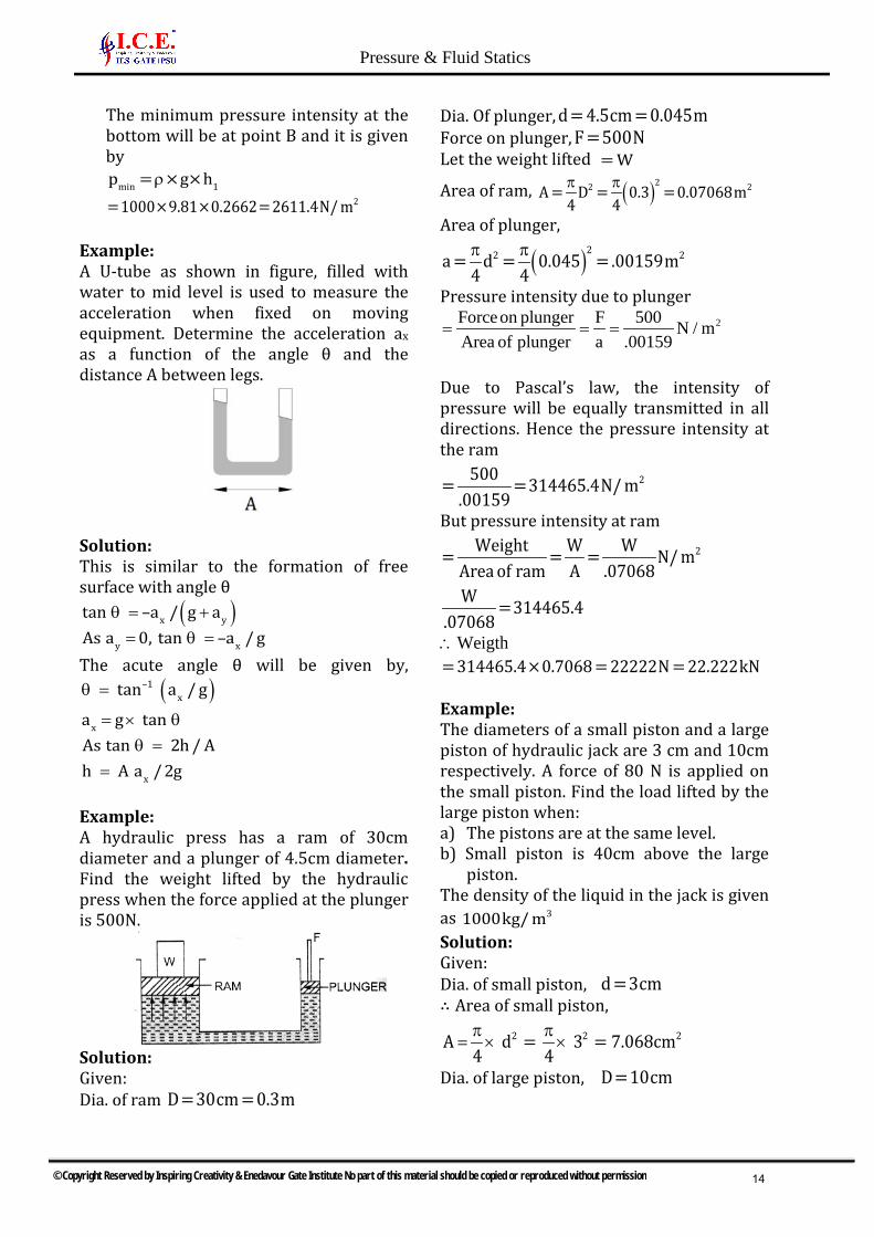
Example: A U-tube as shown in figure, filled with water to mid level is used to measure the acceleration when fixed on moving equipment. Determine the acceleration ax as a function of the angle θ and the distance A between legs.
Solution: This is similar to the formation of free surface with angle θ
( )x y
y x
tan –a / g aAs a 0, tan –a / g
θ = += θ =
The acute angle θ will be given by, ( )–1
x tan a / gθ =
x
x
a g tan As tan 2h / Ah A a / 2g
= × θθ =
=
Example: A hydraulic press has a ram of 30cm diameter and a plunger of 4.5cm diameter. Find the weight lifted by the hydraulic press when the force applied at the plunger is 500N.
Solution: Given: Dia. of ram D=30cm = 0.3m
Dia. Of plunger, d = 4.5cm = 0.045m Force on plunger, F =500N
Let the weight lifted = W
Area of ram, ( )22 2A = D = 0.3 = 0.07068m4 4π π
Area of plunger,
( )22 2a = d = 0.045 = .00159m4 4π π
Pressure intensity due to plunger 2Forceon plunger F 500 N / m
Area of plunger a .00159= = =
Due to Pascal’s law, the intensity of pressure will be equally transmitted in all directions. Hence the pressure intensity at the ram
2500= =314465.4N/ m.00159
But pressure intensity at ram 2Weight W W= = = N/ m
Area of ram A .07068W =314465.4
.07068
Weigth∴ = 314465.4×0.7068 = 22222N = 22.222kN
Example: The diameters of a small piston and a large piston of hydraulic jack are 3 cm and 10cm respectively. A force of 80 N is applied on the small piston. Find the load lifted by the large piston when: a) The pistons are at the same level.b) Small piston is 40cm above the large
piston.The density of the liquid in the jack is given as 31000kg/ mSolution: Given: Dia. of small piston, d =3cm∴ Area of small piston,
π π= × ×2 2 2A d = 3 = 7.068cm
4 4
Dia. of large piston, D=10cm
© Copyright Reserved by Inspiring Creativity & Enedavour Gate Institute No part of this material should be copied or reproduced without permission
Pressure & Fluid Statics
14

∴ Area of larger piston, π
= × 2 2A 10 = 78.54cm4
Force on small piston, =F 80NLet the load lifted = W
a) When the pistons are at the samelevelPressure intensity on small piston
2F 80= N/ ma 7.068
This is transmitted equally to the large piston. ∴ Pressure intensity on the large piston
80=7.068
∴ Force on the large piston = pressure x area
80 78.54 888.967.068
= × =N N
b) When the small piston is 40cm abovethe large pistonPressure intensity on the small piston
2F 80= N/ ma 7.068
∴ Pressure intensity at section A-A F= +a
Pressure intensity due to height
of 40cm of liquid. Pressure intensity due to 40cm of liquid
2= ×g×h =1000×9.81×0.4N/ mρ
2 24
1000×9.81×.40= N/ cm = 0.3924N/ cm10
∴ Pressure intensity at section A-A 80= +0.3924
7.068
+ = 211.32 0.3924 11.71 N/cm ∴ Pressure intensity transmitted to the large piston 2=11.71N/ cm ∴ Force on the large piston = Pressure × Area of the large piston = 11.71× A = 11.71×78.54 = 919.7N
Example: A U-tube manometer is used to measure the pressure of water in a pipe line, which is in excess of atmospheric pressure. The right limb of the manometer contains mercury and is open to water in the main line, if the difference in level of mercury is in the left limb. Determine the pressure of water in the main line, if the difference in level of mercury in the limbs of U-tube is 10 cm and the free surface of mercury is in level with the centre of the pipe. If the pressure of water in pipe line is reduced to 9810N/m2, calculate the new difference in the level of mercury. Sketch the arrangements in both cases. Solution: Given: Difference in mercury level =10 cm =0.1m The arrangement is shown in fig (a)
1st Part Let AP = (pressure of water in pipe line (i.e., at point A)
© Copyright Reserved by Inspiring Creativity & Enedavour Gate Institute No part of this material should be copied or reproduced without permission
Pressure & Fluid Statics
15

The points B and C lie on the same horizontal line. Hence pressure at B should be equal to pressure at C. But pressure at B = Pressure at A + Pressure due to 10cm (or 0.1 m) of water
A= p + ×g×hρ
Where 3=1000kg/ mρ and h = 0.1m
A= p +1000×9.81×0.1 2
A= p +981N/ m …………(i) Pressure at C = pressure at D+ Pressure due to 10 cm of mercury
0 0= 0+ ×g×hρ
Where 𝜌𝜌0 for mercury 3=13.6×1000kg/ m And 0h =10cm = 0.1m ∴ Pressure at C = + × × ×0 (13.6 1000) 9.81 .01= 13341.6N ………(ii) But pressure at B is equal to pressure at C. Hence equating the equations (i) and (ii), we get,
Ap +981=13341.6 ∴ Ap =13341.6 - 981
2
N= 12360.6
m
2nd Part Given, 2
Ap = 9810N/ mFind new difference of mercury level. The arrangement is shown in following figure. In this case, pressure at A is 9810𝑁𝑁/𝑚𝑚2 which is less than the 12360.6𝑁𝑁/𝑚𝑚2. Hence mercury in left limb will rise. The rise of mercury in left limb will be equal to the fall of mercury in right limb as the total volume of mercury remains same. Let x =Rise of mercury in left limb in cm. Then fall of mercury in right limb = x cm The points B, C and D shows the initial conditions whereas points B*, C* and D* show the final conditions. pressure at B* = Pressure at C* Or Pressure at A + Pressure due to (10-x)cm of water
= Pressure at D* + Pressure due to (10-2x) cm of mercury Or A 1 1 D 2 2p + ×g×h = p *+ ×g×hρ ρ
Or 10- x1910+1000×9.81×100
( ) 10-2x= 0+ 13.6×1000 ×9.81×100
Dividing by 9.81, we get 1000 + 100 - 10x = 1360 - 272x Or 272x - 10x = 1360 - 1100 Or 262x = 260
∴ 260x = = 0.992cm262
∴ New difference of mercury =10 2xcm =10 2×0.992− − = 8.016cm
Example: Fig. shows a conical vessel having its outlet at A to which a U-tube monometer is connected. The reading of the manometer given in the figure shows when the vessel is empty. Find the reading of the manometer when the vessel is completely filled with water.
Solution: Vessel is empty: Given: Difference of mercury level
2h = 20cm Let h1 = Height of water above X-X
© Copyright Reserved by Inspiring Creativity & Enedavour Gate Institute No part of this material should be copied or reproduced without permission
Pressure & Fluid Statics
16

S.G. of mercury, 2S =13.6 S.G. of water, 1S =1.0 Density of mercury,
2 =13.6×1000ρ Density of water,
1 =1000ρ Equating the pressure above datum line X-X, we have,
2 2 1 1×g×h = ×g×hρρ Or 113.6×1000×9.81×0.2=1000×9.81×h
1h = 2.72m of water.
Vessel is full of water: When vessel is full of water, the pressure in the right limb will increase and mercury level in the right limb will go down. Let the distance through which mercury goes down in the right limb be, y cm as shown in following figure. The mercury will rise in the left by a distance of y cm. Now the datum line is Z-Z. Equating the pressure above the datum line Z-Z, Pressure in left limb =Pressure in right limb
2y13.6×1000×9.81× 0.2+100
( )1=1000×9.81× 3+ h + y/100
( ) ( )13.6 0.2 2y /100 3 2.72 y /100× + = + +
Or 2.72+27.2y/100=3+2.72+ y/100 Or ( )27.2y- y /100=3.0Or 26.2y =3×100=300
∴ 300y = =11.45cm26.2
The difference of mercury level in two limbs ( )= 20+2y cm of mercury
= 20+2×11.45= 20+22.90 = 42.90cm of mecury ∴ Reading of monometer = 42.90 cm
Example: A single column manometer is connected to a pipe containing a liquid of S.G. 0.9 as shown in Fig. Find the pressure in the pipe if the area of the reservoir is 100 times the area of the tube for the manometer reading shown in Fig. The specific gravity of mercury is 13.6
Solution: Given: Sp. gr. of liquid in pipe, 1S = 0.9 ∴ Density 3
1 = 900kg/ mρSp. gr. of heavy liquid, 2S =13.6 ∴ Density, 2 =13.6×1000ρ
Area of reservoir A= = 100
Area of right limb a
Height of liquid, 1h = 20cm = 0.2m Rise of mercury in right limb,
2h = 40cm = 0.4m Let Ap = Pressure in pipe Using equation,
A 2 2 1 2 2 1 1ap = h g g + h g h g,A
−ρ − ρ ρρ
we get, 1= ×0.4 13.6×1000×9.81- 900×9.81
100 +0.4×13.6×1000×9.81 0.2×900×9.81
−
0.4= 133416 - 8829 +53366.4 -1765.8100
2533.664 53366.4 1765.8N / m= + −
252134N / m= 2N5.21 / cm=
Example: A differential manometer is connected at the two points A and B of two pipes as shown in fig. The pipe A contains a liquid of
© Copyright Reserved by Inspiring Creativity & Enedavour Gate Institute No part of this material should be copied or reproduced without permission
Pressure & Fluid Statics
17

S.G. = 1.5 while pipe B contains a liquid of S.G. = 0.9. The pressures at A and B are 1kgf/cm2and 1.80kgf/cm2 respectively. Find the difference in mercury level in the differential manometer.
Solutions: Given: S.G. of liquid at A, = ∴ ρ =1 1S 1.5 1500 S.G. of liquid at B, = ∴ ρ =2 2S 1.5 1500 Pressure at A,
2 4 2AP =1kgf/ cm =1×10 kgf/ m= × =Q4 210 9.81N / m ( 1kgf 9.81N) Pressure at B,
2BP =1.8kgf/ cm
4 2=1.8×10 kgf/ m= × × =Q4 21.8 10 9.81N / m ( 1kgf 9.81N) Density of mercury 3=13.6×1000kg/ m Taking X-X as datum line Pressure above X-X in the left limb
( ) A=13.6×1000×9.81×h+1500×9.81× 2+3 + p4=13.6×1000×9.81×h+7500×9.81+9.81×10
Pressure above X-X in the right limb ( ) B= 900×9.81× h+2 + p
( ) 4= 900×9.81× h+2 +1.8×10 ×9.81Equating the two pressures, we get
× × + × × 413.6 1000 9.81h 7500 9.81 + 9.81 10( ) 4= 900×9.81× h+2 +1.8×10 ×9.81
Dividing by 1000×9.81 , we get ( )13.6h+7.5+10= h+2.0 ×.9+18
Or
13.6h+17.5 = 0.9h+1.8 +18 = 0.9h+19.8 Or ( )13.6 -0.9 h =19.8 -17.5or12.5h = 2.3
∴2.3h = = 0.181m =18.1cm
12.7
3.5 HYDROSTATIC FORCES ON SURFACES
In fluid statics, there is no relative motion between adjacent fluid layers, and thus there are no shear (tangential) stresses in the fluid trying to deform it. The only stress we deal with in fluid statics is the normal stress, which is the pressure, and the variation of pressure is only due to the weight of the fluid. The force exerted on a surface by a fluid at rest is normal to the surface at the point of contact since there is no relative motion between the fluid and the solid surface, and thus no shear forces can act parallel to the surface. Fluid statics is used to determine the forces acting on floating or submerged bodies and the forces developed by devices like hydraulic presses and car jacks. The design of many engineering systems such as water dams and liquid storage tanks requires the determination of the forces acting on the surfaces using fluid statics.
3.5.1 TOTAL PRESSURE
Force is exerted by a static fluid on a surface, either plane or curved when fluid comes in contact with the surfaces. This force always acts normal to the surface.
3.5.2 CENTRE OF PRESSURE
It is defined as the point of application of the total pressure on the surface. The submerged surfaces may be 1) Vertical plane submerged2) Horizontal plane surface3) Inclined plane4) Curved surface
© Copyright Reserved by Inspiring Creativity & Enedavour Gate Institute No part of this material should be copied or reproduced without permission
Pressure & Fluid Statics
18

3.5.3 VERTICAL PLANE SURFACE SUBMERGED IN
LIQUID
Consider a plane vertical surface of arbitrary shape immersed in a liquid as shown A = Total area of surface h = Distance of C. G. of the area from free surface of liquid G = Centre of Gravity of plane surface P = Centre of Pressure h∗ = Distance of centre of pressure from free surface of liquid.
a) Total PressurePressure Intensity at strip = ρghArea of strip dA = b. dhForce on strip dF = ρ. g. h. b. dhTotal pressure force on the wholesurface is
sdF ρghbdh=∫ ∫= ρ∫ ∫s
dF g h.dA
F .g.h.A= ρ
h.dA∫ is moment of surface area about
free surface of liquid is equal moment of C.G. about free surface.
h.dA A.h=∫
b) Centre of Pressure: (𝐡𝐡∗)Principle of Moments: Moment of theresultant force about an axis is equal tothe sum of moments of the componentsabout the same axis.Ft. h∗ = ∑moments about free surface ofliquid. …(1)
= ρ∑ ∫moments dA.h. gh
= ρ ∫ 2g bh dh
= ρ ∫ 2gb h dhWhere,
2odA.h I=∫ is the moment of Inertia of
surface about free surface of liquid. = ρ∑ 0moments gI …(2)
∴ = ρ*t oF .h gIρ
=ρ
* ogIh
gh.A
=* 0Ih
hAWhere, h is the distance of C.G. from free surface A is the area. From II axis theorem
2o C.G.I I Ah= +
2* C.G.I +Ah
h =h.A
1) h∗ lies below the C.G. of the surface2) It is independent of the density of
liquid & depends only on surfacearea.
3.5.4 HORIZONTAL PLANE SURFACE SUBMERGED IN LIQUID
As every point of the surface is at the same depth from free surface of the liquid, the pressure intensity will be equal on the entire surface and equal to P = ρgh where h is depth of surface
1F ρg h Area= × *h h h= =
3.5.5 INCLINED PLANE SUBMERGED IN LIQUID
© Copyright Reserved by Inspiring Creativity & Enedavour Gate Institute No part of this material should be copied or reproduced without permission
Pressure & Fluid Statics
19

Let A = Total area of surface h = Distance of C. G. of the area from free surface of liquid G = Centre of Gravity of plane surface P = Centre of Pressure h∗ = Distance of centre of pressure from free surface of liquid.
a) Total PressurePressure intensity on the strip P ρgh=Pressure force dF on the strip
= × ρdF P dA = ghdATotal pressure force on the whole area,F dF ghdA= = ρ∫ ∫From fig.
*
*
h h hsinθy y y
= = =
∴ h y sinθ= ∴ F ρg y sinθdA= ∫But y dA Ay=∫ is the moment of
surface at distance ‘y’ ∴ F ρgsinθAy= ∴ F = ρg A h ( )y h sin= θQNote: the above expression of force is for fluid with no pressure acting on the surface. If pressure acts on the surface
0F P A ρg Ah= +
b) Centre of PressurePressure force on the strip,dF gh dA gy sin dA= ρ = ρ θMoment of the force, dF, about axis O-O
dF y= ×
ρgy sinθdA.y= Sum of moments of all such forces about O − O 2ρgsinθy dA= ∫
2ρgsinθ y dA= ∫Where,
2y dA =∫ Moment of Inertia of the
surface about O − O = Io ∴ Sum of moments of all force
oρgsinθI=*
oF y ρgsinθI× =
* oρgsinθIy
ρg Ah=
* oI sinθy
Ah=
2* 0I sinh
Ahθ
=
2* 2
Gsinh (I Ay )Ah
θ= +
2 2*
G 2
sin θ Ahh IAh sin θ
= +
a) Rectangle
A=ab, 3
xx,CabI12
=
b) Circle
42
xx,CRA R , I4
π= π =
© Copyright Reserved by Inspiring Creativity & Enedavour Gate Institute No part of this material should be copied or reproduced without permission
Pressure & Fluid Statics
20

c) Triangle
3
xx,CabA ab, I4
π= π =
d) Triangle
3
xx,Cab abA , I2 36
= =
e) Semicircle
24
xx,CRA , I 0.109757R2
π= =
f) Semi ellipse
23
xx,CabA , I 0.109757ab2
π= =
3.5.6 CURVED SURFACE SUB-MERGED IN LIQUID
For a submerged curved surface, the determination of the resultant hydrostatic force is more involved since it typically requires the integration of the pressure forces that change direction along the curved surface. The way to determine the resultant hydrostatic force FR acting on a two-dimensional curved surface is to determine the horizontal and vertical components Fx and Fy separately. This is done by considering the free-body diagram of the liquid block enclosed by the curved surface and the two plane surfaces (one horizontal and one vertical) passing through the two ends of the curved surface. Note that the vertical surface of the liquid block considered is simply the projection of the curved surface on a vertical plane, and the horizontal surface is the projection of the curved surface on a horizontal plane.
The resultant force acting on the curved surface is given by
2 2R x yF F F= +
Inclination of resultant with horizontal is given by
y
x
Ftan
Fθ =
1) The horizontal component of thehydrostatic force acting on a curvedsurface is equal (in both magnitude andthe line of action) to the hydrostatic
© Copyright Reserved by Inspiring Creativity & Enedavour Gate Institute No part of this material should be copied or reproduced without permission
Pressure & Fluid Statics
21

force acting on the vertical projection of the curved surface.
2) The vertical component of thehydrostatic force acting on a curvedsurface is equal to the weight of liquidsupported by the curved surface.
Example: A rectangular plane surface is 2m wide and 3m deep. It lies in vertical plane in water. Determine the total pressure and position of centre of pressure on the plane surface when it’s upper edge is horizontal and (a) coincides with water surface, (b) 2.5m below the free water surface.
Solution: Given: Width of plane surface, b=2m Depth of plane surface, d=3m
a) Upper edge coincides with watersurfaceTotal pressure is given by equation asF = gAhρ
Where, 3 21000kg / m , g 9.81m / sρ = =
2 1A 3 2 6m , h 3 1.5m2
= × = = × =
F 1000 9.81 6 1.5 = 88290N∴ = × × ×
Depth of centre of pressure is given by equation as
* GIh hAh
= +
Where, GI = M.O.I. about C.G. of the area of
surface 3 3
4
*
bd 2 3 4.5m12 12
4.5h 1.5 0.5+1.5 = 2.0m6 1.5
×= = =
∴ = + =×
b) Upper edge is 2.5, below watersurface
Total pressure (F) is given by F = gAhρ Where, h =Distance of C.G. from free surface of water
= 32.5+ = 4.0m2
∴ F =1000×9.81×6×4.0 = 235440N Center of pressure is given by
GIh* = + h
AhWhere
GI = 4.5,A = 6.0,h = 4.0
4.5h* = + 4.06.0×4.0
= 0.1875+ 4.0= 4.1875= 4.1875m.
Example: A circular opening, 3m diameter, in a vertical side of a tank is closed by disc of 3m diameter which can rotate a horizontal diameter. Calculate:
© Copyright Reserved by Inspiring Creativity & Enedavour Gate Institute No part of this material should be copied or reproduced without permission
Pressure & Fluid Statics
22

i) The force on the disc, andii) The torque required to maintain the
disc in equilibrium in the verticalposition when the head of water abovethe horizontal diameter is 4m.
Solution: Given:
Dia. of opening d =3m
Area, 2 2A = ×3 =7.0685m4π
Depth of C.G. h = 4m
i) Force on the disc is given by equation asF = gAh =1000×9.81×7.0685×4.0ρ= 277368N = 277.368kN
ii) To find the torque required to maintainthe disc in equilibrium, first calculatethe point application of force acting onthe disc, i.e., center of pressure of theforce F. The depth of centre of pressure(h*) is given by equation as
4
G
2
dI 64h* = + h = + 4.0Ah d ×4.0
4
π
π
4G I d
64π =
Q
2 2d 3= + 4.0= + 4.0= 0.14+ 4.0= 4.14m16×4.0 16×4.0
The force F is acting at a distance of 4.14 m from free surface. Moment of this force about horizontal diameter X-X
( ) ( )= F h* -h = 277368 4.14 - 4.0 =38831NmHence a torque of 38831 Nm must be applied on the disc in the clockwise direction.
Example: A pipe line which is 4m in diameter contains a gate valve. The pressure at the centre of the pipe is 219.6N/ cm . If the pipe is filled with oil of S.G. 0.87; find the force exerted by the oil upon the gate and position of centre of pressure. Solution:
Given: Dia. of pipe, d = 4m∴ Area,
2 2A = ×4 = 4pm4π
∴Density of oilρ = × = 30 0.87 1000 870kg / m
∴ Weight density of oil, 3
0 0w = ×g = 870×9.81N/ mρ
Pressure at the centre of pipe, 32 4p =19.6N/ cm =19.6×10 N/ m
∴ Pressure head at the centre 4
0
p 19.6×10= = = 22.988mw 870×9.81
∴ The height of equivalent free oil surface from the centre of pipe =22.988m The depth of C.G. of the gate valve from free oil surface h = 22.988m F = gAhρWhere =ρ density of oil 3= 870kg/ m F = 870×9.81×4 ×22.988 = 2465500N = 2.465MNπ(ii)Position of centre of pressure (h*) is given as
42 2
G
2
dI d 464h* = + h = + h = + h = +22.988Ah 16h 16×22.988d ×h
4
π
π
= 0.043+22.988 = 23.031m Or, centre of pressure is below the centre of the pipe by a distance of 0.043m
© Copyright Reserved by Inspiring Creativity & Enedavour Gate Institute No part of this material should be copied or reproduced without permission
Pressure & Fluid Statics
23

Example: A vertical sluice gate is used to cover an opening in a dam. The opening is 2m wide and 1.2 m high. On the upstream of the gate, the liquid of S.G. 1.45 lies upto a height of 1.5m above the top of the gate. Find the resultant force acting on the gate and position of centre of pressure. Find also the force acting horizontally at the top of the gate which is capable of opening it. Assume that the gate is hinged at the bottom.
Solution: Given: Width of gate, b= 2m Depth of gate, d =1.2m ∴ Area,
2A = b×d = 2×1.2= 2.4m Sp. gr. of liquid=1.45 ∴ Density of liquid,
31 =1.45×1000=1450kg/ mρ
Let 1F = Force exerted by the fluid of sp. gr 1.45 on gate
2F = Force exerted by water on the gate. The force
1F = is given by 1 1 1F = g× A×hρWhere
21 =1.45×1000=1450kg/ mρ
1h = Depth of C.G. of gate from free surface of liquid
1.2=1.5+ = 2.1m2
∴ 1F =1450×9.81×2.4×2.1=71691N Similarly, 2 2 2F = g.Ahρ Where 3
2 =1000kg/ mρ
2h = Depth of C.G. of gate from free surface of water
1= ×1.2= 0.6m2
∴ 2F =1000×9.81×2.4×0.6 =14126N
(i)Resultant force on the gate = − = − =1 2F F 71691 14126 57565N (ii) Position of centre of pressure of resultant force. The force 1F will be acting at a depth of
1h * from free surface of liquid, given by the relation
G1
Ih* = + h
Ahwhere
3 34
Gbd 2×1.2I = = = 0.288m12 12
∴
1.288h * = +2.1= 0.0571+2.1= 2.1571m
2.4×2.1
∴Distance of 1F from hinge
( ) 1= 1.5+1.2 h * = 2.7 2.1571= 0.5429m− −
The force 2F will be acting at a depth of 2h * from free surface of water and is given by
G2 2
2
Ih * = + h
AhWhere
4 2G 2I = 0.288m ,h = 0.6m,A = 2.4m
2.288h * = +0.6 = 0.2+0.6 = 0.8m
2.4×0.6
Distance of 2F from hinge =1.2 0.8 = 0.4m− The resultant force 57565N will be acting at a distance given by
71691×.5429 14126×0.4=57565
−
38921-5650.4= m above hinge57565
= 0.578m above the hinge
© Copyright Reserved by Inspiring Creativity & Enedavour Gate Institute No part of this material should be copied or reproduced without permission
Pressure & Fluid Statics
24

(iii)Force at the top of gate which is capable of opening the gate. Let F is the force required on the top of the gate to open it as shown in fig. Taking the moments of F, 1 2F andF about the hinge, we get
2 10.4F×1.2+F F .5429× = × Or
1 2F ×.5429 F ×0.4F =
1.2−
71691×.5429-14126×0.4 38921-5650.4= =1.2 1.2
= 27725.5N.
Example: A tank contains water up to a height of 0.5m above the base. An immiscible liquid of sp. gr. 0.8 is filled on the top of water up to 1m height. Calculate: i) total pressure on one side of the tank,ii) the position of centre of pressure from
one side of the tank, which is 2m wideSolution: Given: Depth of water = 0.5mDepth of liquid=1m Sp. gr of liquid= 0.8 Density of liquid,
31 = 0.8×1000= 800kg/ mρ
Density of water, 3
2 =1000kg/ mρWidth of tank= 2m (i) Total pressure on one side is calculated by drawing pressure diagram, which is shown in fig . Intensity of pressure on top, Ap = 0Intensity of pressure on D (or DE),
D 1 1p = g.hρ2= 800×9.81×1.0=7848N/ m
Intensity of pressure on base (or BC), B 1 1 2p = gh + g×0.5ρ ρ
2
12753N=7848+1000×9.81×0.5=7848+ 4905=m
Now Force, 1F = Area of ADE × Width of tank∆
1 1= × AD×DE×2.0= ×1×7848×2.0=7848N2 2
Force, 2F = Areaof rectangle DBFE× Width of tank
= 0.5×7848×2=7848N 3F = Area of EFC × Width of tank∆
1 1= ×EF×FC×2.0= ×0.5×4905×2.0= 2452.5N2 2
∴Total force F = F1 + F2 + F3 =7848+7848+2452.5=18148.5N
(ii) Centre of pressure (h*). Taking the moments of all forces about A, we get
1 2 32 1 2F×h* = F × AD+F AD+ BD +F AD+ BD3 2 3
2 0.5 218148.5×h* =7848× ×1+7848 1.0+ +2452.5 1.0+ ×.53 2 3
=5232+9810+3270=18312
∴ 18312h* = =1.009m from top18148.5
Example: A circular plate 3.0m diameter is immersed in water in such a way that their greatest and least depths below the free surface are 4m and 1.5m respectively. Determine the total pressure on one face of the plate and position of the centre of pressure. Solution: Given Dia. of plate, d =3.0m ∴ Area,
( )22 2A = d = 3.0 =7.0685m4 4π π
Distance DC =1.5m,BE = 4m
© Copyright Reserved by Inspiring Creativity & Enedavour Gate Institute No part of this material should be copied or reproduced without permission
Pressure & Fluid Statics
25

Distance of C.G. from free surface = h = CD+GC sin =1.5+1.5sinθ θ But
AB BE- AE 4.0- DC 4.0-1.5sin = = = =BC BC 3.0 3.0
θ
2.5= = 0.83333.0
∴ h =1.5+1.5×.8333=1.5+1.249= 2.749m
i) Total Pressure (F)F = gAhρ=1000×9.81×7.0685×2.749=190621N
ii) Centre of pressure (h*)Using equation, we have
2GI sin
h* = + hAh
θ
Where
( ) ( )4 4 4GI = 3 =3.976m
64 64d =π π
( )3.976× .8333 ×.8333h* = +2.749= 0.1420+2.749
7.0685×2.749= 2.891m.
Example: If in the above problem, the given circular plate is having a concentric circular hole of diameter 1.5m, then calculate the total pressure and position of the centre of pressure on one face of the plate. Solution: Given: [referring to given figure] Dia. of plate, d =3.0m ∴ Area of solid plate
( )22 2= d = 3 =7.0685m4 4π π
Dia. of hole in the plate, 0d =1.5m
∴Area of hole ( )22 20= d = 1.5 =1.7671m
4 4π π
∴Area of the given plate A = Area of solid plate − Area of hole
2=7.0685-1.7671=5.3014m Distance of CD=1.5,BE = 4m Distance of C.G. from the free surface, h = CD+GCsinθ =1.5+1.5sinθ But
AB BE- AE 4 -1.5 2.5sin = = = =BC BC 3 3
θ
∴2.5h =1.5+1.5× =1.5+1.25= 2.75m3
i) Total pressure force (F)F = gAhρ=1000×9.81×5.3014×2.75=143018N =143.018kN
ii) Position of centre of pressure (h*)Using equation, we have
2GI sin
h* = + hAh
θ
where 4 4 4 4 4
G 0I = d - d = 3 -1.5 m64 64π π
2 2 2 2 20A = d - d = 3 -1.5 m
4 4π π
2.5sin = and h = 2.753
θ
© Copyright Reserved by Inspiring Creativity & Enedavour Gate Institute No part of this material should be copied or reproduced without permission
Pressure & Fluid Statics
26

∴
24
2 2
4 2.53 1.5 ×64 3
h* = +2.753 1.5 ×2.75
4
−
π−
π
= 0.177+2.75= 2.927m
Example: An inclined rectangular sluice gate AB, 1.2m x 5m size as shown in fig is installed to control the discharge of water. The end A is hinged. Determine the force normal to the gate applied at B to open it.
Solution: Given:
2A = Area of gate =1.2×5.0= 6.0m Depth of C.G. of the gate from free surface of the water = h = DG = BC- BE =5.0 BG sin45°−
− × =15.0 0.6 4.576m2
The total pressure force (F) acting on the gate, = ρF gAh
= × × ×1000 9.81 6.0 4.576 =269343N This force is acting at H, where the depth of h from free surface is given by
2GI sin
h* = + hAh
θ
Where, GI = M.O.I. of gate 3 3bd 5.0×1.2= = = 0.72m
12 12
∴Depth of centre of pressure
20.72×sin 45°h* = + 4.576 = .013+ 4.576 = 4.589m6×4.576
But from fig, h* = sin45°OH
∴h* 4.589OH = = = 4.589× 2 = 6.489m
1sin45°2
Distance, 5BO = =5× 2 =7.071msin45°
Distance, BH = BO OH = 0.071 6.489= 0.582m− −
∴Distance, AH = AB BH =1.2 0.582= 0.618m− − Taking the moments about the hinge A
( )P× AB= F× AH
Where P is the force normal to the gate applied at B ∴ P×1.2= 269343×0.618
∴ 269343×0.618P = =138708N1.2
Example: Fig shows a quadrant shaped gate of radius 2m. Find the resultant force due to water per meter length of the gate. Find also the angle at which the total force will act.
Solution: Given: Radius of gate =2m Width of gate =1m Horizontal Force,
xF = Force on the projected area of the curved surface on vertical plane = Force on BO = gAhρ Where,
2 1A = Area of BO = 2×1= 2m ,h = ×2=1m2
xF =1000×9.81×2×1=19620N
© Copyright Reserved by Inspiring Creativity & Enedavour Gate Institute No part of this material should be copied or reproduced without permission
Pressure & Fluid Statics
27

This will act at depth of 2 4×2= m3 3
from
free surface of liquid, Vertical Force,
yF = Weight of water (imagined) supported by AB = g× Areaof AOB×1.0ρ
( )4=1000×9.81× 2 ×1.0=30819N
4π
This will act a distance of 4R 4 0.2 = 0.848m from OB.3 3
×=
π π
∴Resultant force, F is given by 2 2x yF = F +F
= +2 219620 30819=36534.4N. The angle made by the resultant with horizontal is given by
y
x
F 30819tan = = =1.5708F 19620
θ
∴ -1= tan 1.5708 =57°31'θ
Example: Find the horizontal and vertical component of water pressure acting on the face of a sector gate of 90° with radius 4m as shown in fig. Take width of gate as unity.
Solution: Given: Radius of gate, R=4m Horizontal component of force acting on the gate is
xF = Force on area of gate projected on vertical plane = Force on area ADB = gAhρ Where A = AB× Width of gate
= 2× AD×1 ( )AB= 2ADQ2= 2×4×sin45° = 8×.707 =5.656m
{ }AD= 4sin45°Q
AB 5.656h = = = 2.828m2 2
∴ xF =1000×9.81×5.656×2.828N =156911N Vertical component
yF = Weight of water supported or enclosed by the curved surface = Weight of water in portion ACBDA= g× Area of ACBDA× Width of gateρ
1000 9.81 1 = × × − ∆ × Area of sector ACBOA Area of ABO
2 AO×BO= 9810× R AOB is a right angled4 2
− ∆π
Q
2 4×4= 9810× 4 = 44796N4 2
−
π
Example: A cylindrical gate of 4m diameter & 2m long has water on its both sides as shown in Fig. Determine the magnitude, location and direction of the resultant force exerted by the water on the gate. Find also the least weight of the cylinder so that it may not be lifted away from the floor.
Solution: Given: Dia. of gate =4m Radius =2m (i) The force acting on the left sides of the cylinder are The horizontal component,
1xF
Where 1xF = Force of water on area
projected on vertical plane = Force on area AOC =ρgA h Where A = AC × width = 4×2= 8cm2
© Copyright Reserved by Inspiring Creativity & Enedavour Gate Institute No part of this material should be copied or reproduced without permission
Pressure & Fluid Statics
28

1h 4 2m2
= × =
1xF = 1000×9.81×8×2
=156960N
1yF = Weight of water enclosed by ABCOA
2 2=1000×9.81× R ×2.0= 9810× ×2 ×2.0=123276N2 2
π π
Right Side of the Cylinder
2x 2 2F = gA h =ρ Force on vertical area CO 21000 9.81 (2 2)2
= × × × × =39240N
2yF = Weight of water enclosed by DOCD
2= g× R × Width of gate4
ρ
π
2=1000×9.81× ×2 ×2= 61638N4π
∴ Resultant force in the direction of x, 1 2x x xF = F F =156960 39240=117720N− −
Resultant force in the direction of y,
1 2y y yF = F +F =123276+61638 =184914N
i) Resultant force, F is given as
( ) ( )2 22 2x yF = F +F = 117720 + 184914 = 219206N
ii) Direction of resultant force is givenby
y
x
F 184914tan = = =1.5707F 117720
θ
=57°31'∴ θ
iii) Location of the resultant forceForce,
1xF acts at a distance of
2×4 = 2.67m3
from the top surface of
water on left side, while 2xF acts at a
distance of 2 ×2=1.33m3
from free
surface on the right side of the cylinder .The resultant force xF in the direction of x will act at a distance of y from the bottom as
1 2x x xF × y = F 4 2.67 F 2 1.33 − − − Or 117720 y 156960 1.33 39240 .67× = × − ×
208756.8 26290.8 182466= − =
∴ 182466y = =1.55m117720
from the bottom
Force 1yF acts at a distance 4R
3π from
AOC or at a distance 4 2.0 0.8488m3×
=π
from AOC towards left of AOC.
Also 2yF acts at a distance 4R 0.8488m
3=
π
from AOC towards the right of AOC. The resultant force yF will act at a distance x from AOC which is given by
1 2y y yF × x = F ×.8488 F ×.8488−
Or 184914× x =123276×.8488 61638×.8488− .8488 123276 61638 52318.4 = − =
∴ 52318.4x = = 0.2829m184914
from AOC
iv) Least weight of cylinder. The resultantforce in the upward direction is
yF =184914NThus the weight of cylinder should notbe less than the upward force yF . Hence, weight of cylinder should be atleast 184914N
Example:
A dam has a parabolic shape 2
00
xy = yx
as shown in fig. below having 0x = 6m and =0y 9m. The fluid is water with density
3=1000kg/ m . Compute the horizontal, vertical and the resultant thrust exerted by water per meter length of the dam.
© Copyright Reserved by Inspiring Creativity & Enedavour Gate Institute No part of this material should be copied or reproduced without permission
Pressure & Fluid Statics
29
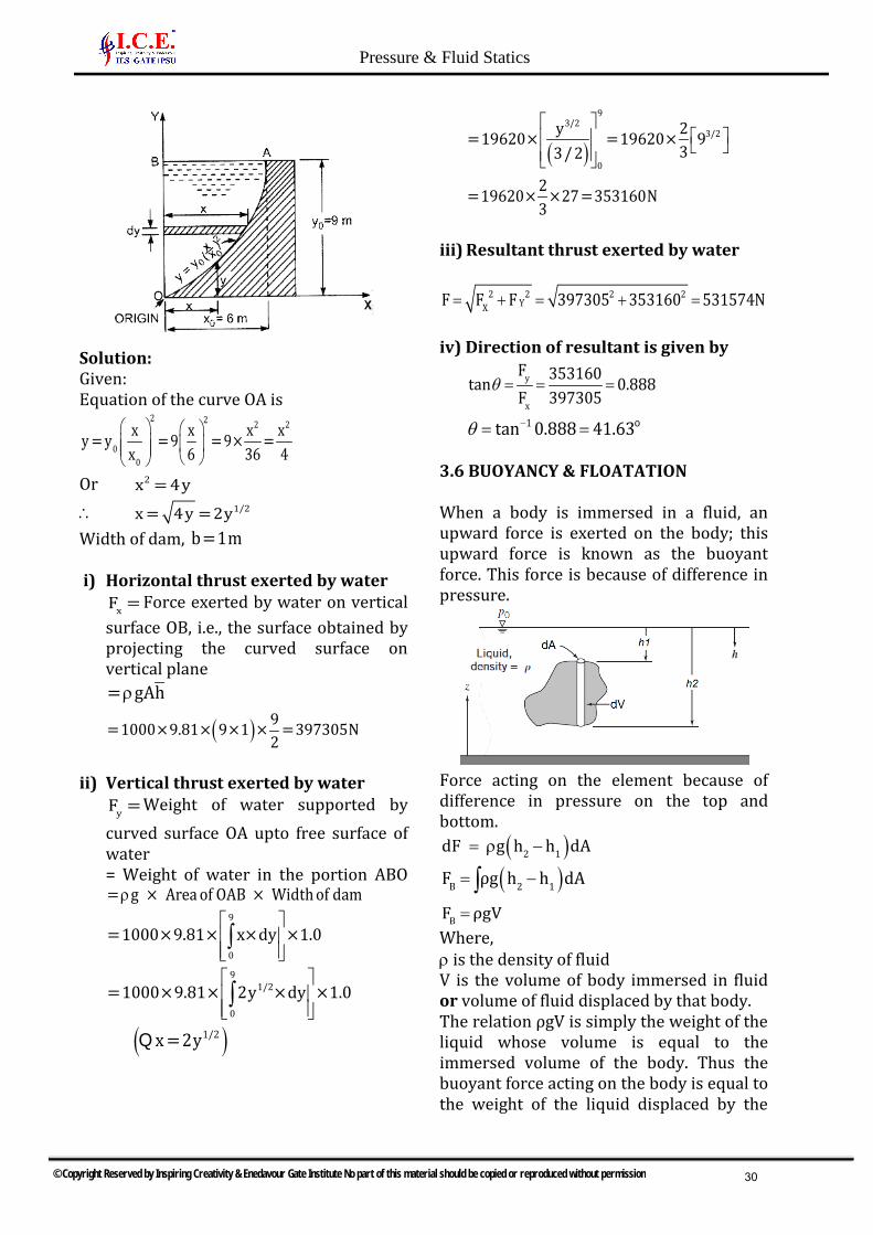
Solution: Given: Equation of the curve OA is
2 2 2 2
00
x x x xy = y = 9 = 9× =x 6 36 4
Or 2x = 4y
∴ 1/2x = 4y = 2yWidth of dam, b=1m
i) Horizontal thrust exerted by waterxF = Force exerted by water on vertical
surface OB, i.e., the surface obtained byprojecting the curved surface onvertical plane= gAhρ
( ) 9=1000×9.81× 9×1 × =397305N2
ii) Vertical thrust exerted by wateryF = Weight of water supported by
curved surface OA upto free surface ofwater= Weight of water in the portion ABO= g × Area of OAB × Width of damρ
9
0
=1000×9.81× x×dy ×1.0 ∫
91/2
0
=1000×9.81× 2y ×dy ×1.0 ∫
( )1/2x = 2yQ
( )
93/2
3/2
0
y 2=19620× =19620× 933/ 2
2=19620× ×27 =353160N3
iii) Resultant thrust exerted by water
= + = + =2 2 2 2YXF F F 397305 353160 531574N
iv) Direction of resultant is given by
θ = = =y
x
F 353160tan 0.888F 397305
θ −= = o1tan 0.888 41.63
3.6 BUOYANCY & FLOATATION
When a body is immersed in a fluid, an upward force is exerted on the body; this upward force is known as the buoyant force. This force is because of difference in pressure.
Force acting on the element because of difference in pressure on the top and bottom.
( )2 1dF g h h dA= ρ −
( )B 2 1F ρg h h dA= −∫BF ρgV=
Where, ρ is the density of fluid V is the volume of body immersed in fluid or volume of fluid displaced by that body. The relation ρgV is simply the weight of the liquid whose volume is equal to the immersed volume of the body. Thus the buoyant force acting on the body is equal to the weight of the liquid displaced by the
© Copyright Reserved by Inspiring Creativity & Enedavour Gate Institute No part of this material should be copied or reproduced without permission
Pressure & Fluid Statics
30

body. Note that the buoyant force is independent of the distance of the body from the free surface. It is also independent of the density of the solid body
3.6.1 CENTRE OF BUOYANCY
The buoyant force acting on a body immersed in a fluid is equal to the weight of the fluid displaced by the body, and it acts upward through the centroid of the displaced volume. The centroid of displaced fluid is known as centre of buoyancy.
3.6.2 META CENTRE It is defined as the point about which a body starts oscillating when the body is tilled by a small angle. The Meta centre may also be defined as the intersection point of line of action of buoyant force and normal to the body when the body is tilted by an angle.
Meta centric height = GM ( )I Moment of Inertia about yyof the plan
BGVolumeof fluid displaced
= −
B.G is the distance between CG & CB points.
3.6.3 OSCILLATION OF A FLOATING BODY
When body floats in the fluid and it is given a disturbance in clockwise direction or anti
clock wise direction. The body oscillates about its metacenter. The time period of oscillation is given by
2kT 2πGM.g
=
Where, GM is Meta centric ht K is radius of gyration
3.6.4 CONDITIONS OF EQUILIBRIUM OF SUBMERGED & FLOATING BODIES
There are 3 types of equilibrium conditions i) Stable Equilibriumii) Neutral equilibriumiii) Unstable equilibrium
i) Stable equilibrium:Any small disturbance (someone moves the ball to the right or left) generates a restoring force (due to gravity) that returns it to its initial position.
ii) Neutral equilibrium:If someone moves the ball to the right or left, it will stay at its new location. It has no tendency to move back to its original location, nor does it continue to move.
iii) Unstable Equilibrium:It is a situation, in which the ball may be at rest at the moment, but any disturbance, even an infinitesimal one, causes the ball to roll off the hill—it does not return to its original position; rather it moves away from it.
3.6.4.1 STABILITY IN SUBMERGED BODIES
1) Stable Equilibrium: When W = FB andpoint B is above G. A small displacementin clockwise direction, gives couple due
© Copyright Reserved by Inspiring Creativity & Enedavour Gate Institute No part of this material should be copied or reproduced without permission
Pressure & Fluid Statics
31

to FB & weight in anticlockwise direction. Thus, the body will return to its original position. Hence, equilibrium is stable.
2) Unstable Equilibrium: If W = FB andpoint B is below point ‘G’. A smalldisplacement to the body, in the clockwise direction, gives couple due toW & FB also in the clockwise direction.Thus, body will move away from itsoriginal position. Hence, equilibrium isunstable
3) Neutral Equilibrium: If FB = W and B& G are at the same point, thedisplacement of body does not result inany couple of Wt & FB. Body remains atits displaced position
Stable equilibrium Unstable equilibrium
3.6.42 STABILITY IN FLOATING BODY
The stability of floating body is determined from position of metacentre(M). In case of floating body, the weight of body is equal to the buoyant force.
1) Stable Equilibrium: When M is aboveG, because of a small displacement tothe body in the clock wise direction, thecouple between Wt & FB causes rotationin anti-clockwise direction.
2) Unstable Equilibrium: When M isbelow G, because of small displacementto the body in the clock wise direction,the couple between Wt & FB causesrotation in clockwise direction.
3) Neutral: If M lies at the C.G. of body, thedisplacement of body does not result inany couple of Wt & FB. Body remains atits displaced position.
Stable equilibrium
Unstable equilibrium
Example: Find the volume of the water displaced and position of centre of buoyancy for a wooden block of width 2.5 m and of depth 1.5m, when it floats horizontally in water. The density of wooden block is 3650kg/ m and its length is 6.0m. Solution: Given: Width = 2.5m Depth = 1.5m Length = 6.0m Volume of the block
3= 2.5×1.5×6.0= 22.50mDensity of wood, 3= 65kg/ mρ
∴ Weight of block = ×g× Volumeρ = 650×9.81×22.50N = 143471N For equilibrium, the weight of water displaced = Weight of wooden block = 143471N ∴Volume of water displaced
© Copyright Reserved by Inspiring Creativity & Enedavour Gate Institute No part of this material should be copied or reproduced without permission
Pressure & Fluid Statics
32

3Weight of water displaced 143471= = =14.625mWeight density of water 1000×9.81
Position of center of Buoyancy: Volume of wooden block in water = Volume of water displaced Or
32.5×h×6.0=14.625m , Where, h is depth of wooden block in water
∴ 14.625h = = 0.975m
2.5×6.0
∴ Centre of Buoyancy 0.975= = 0.4875m from base
2
Example: Find the density of a metallic body which floats at the interface of mercury of S.G. 13.6 and water such that 40% of its volume is sub-merged in mercury and 60% in water. Solution: Let the volume of the body 3= Vm Then volume of body sub-merged in mercury
340= V = 0.4Vm100
Volume of body sub-merged in water 360= V = 0.6Vm
100
For the equilibrium of the body Total buoyant force (upward force) =Weight of the body But total buoyant force= Force of buoyancy due to water + Force of buoyancy due to mercury Force of buoyancy due to water = Weight of water displaced by body = Density of water × Volume of mercury displaced
=1000 g Volume of body in water× ×
= 1000×g ×0.6× VN And, force of buoyancy due to mercury = Weight of mercury displaced by body = g × Density of water× Volume of mercury displaced =g×13.6×1000× volume of body in mercury = g×13.6×1000×0.4VN Weight of the body =Density x g x Volume of body ∴ For equilibrium, we have Total buoyant force =Weight of the body 1000×g×0.6× V+13.6×1000×g×.4V = ×g× VρOr
3= 600+13600×.4 = 600+54400= 6040.00kg/ mρ∴Density of the body 3= 6040.00kg/ m
Example: A float valve regulates the flow of oil of S.G. 0.8 into a cistern. The spherical float is 15 cm in diameter. AOB is a weightless link carrying the float at one end, and a valve at the other end which closes the pipe through which oil flows into the cistern. The link is mounted on a frictionless hinge at O and the angle AOB is 135°. The length of OA is 20cm, and the distance between the centre of the float and the hinge 50 cm. When of the flow is stopped AO will be vertical. The valve is to be pressed on to the seat with a force of 9.81 N to completely stop the flow of oil into the cistern. It was observed that the flow of oil is stopped when the free surface of oil in the cistern is 35 cm below the hinge. Determine the weight of the float.
Solution: Given: Sp. gr. of oil =0.8 ∴ Density of oil
© Copyright Reserved by Inspiring Creativity & Enedavour Gate Institute No part of this material should be copied or reproduced without permission
Pressure & Fluid Statics
33

30= = 0.8×1000 800kg/ mρ =
Dia. of float, D=15cm AOB=135°∠
OA = 20cm Force, P=9.81N OB=50 cm Let the weight be W.
When the flow of oil is stopped, the centre of float is shown in Fig. The level of oil is also shown. The centre of float is below the level of oil, by a depth ‘h’ From BOD,∆
OD OC+CD 35+ hsin45° = = =OB OB 50
50×sin45° =35+ h Or 1h =50× 35=35.355 35= 0.355cm = .00355m2− −
The weight of float is acting through B, but the upward buoyant force is acting through the centre of weight of oil displaced Volume of oil displaced :
3 22= r + h× r3π π
D 15r = = =7.5cm2 2
( ) ( )3 2 32= × × 0.75 +.00355× × 0.75 = 0.000945m3
π π
=Weight of oil displaced 0= ×g× Volume of oilρ
= 800×9.81×0.00945=7.416N The buoyant force and weight of the float passes through the same vertical line, passing through B. Let the weight of float is W. Then net vertical force on float =Buoyant force –Weight of float = (7.416-W) Taking moments about the hinges O, we get
( ) ( )P×20= 7.416 W ×BD= 7.416 W ×50×cos45°− −
Or ( )9.81×20= 7.416 W ×35.355−
∴20×9.81W =7.416 =7.416 5.55=1.866N35.355
− −
Example: A rectangular pontoon is 5m long, 3m wide and 1.20m high. The depth of immersion of the pontoon is 0.80m in sea water. If the centre of gravity is 0.6m above the bottom of the pontoon, determine the Meta – centric height. The density for sea water
3=1025kg/ m Solution: Given: Dimension of pontoon 5m 3m 1.20m= × ×Depth of immersion =0.8m Distance AG=0.6m
Distance 1AB= ×Depth of immersion2
1= ×.8 = 0.4m2
Density for sea water 3=1025kg/ m Meta-centre height GM, given by equation as
IGM = BG∀−
Where I = Moment of Inertia of the plan of the pontoon about Y-Y axis
3 4 41 45= ×5×3 m = m12 4
∀ = Volume of the body sub- merged in water
3=3×0.8×5.0=12.0m BG = AG = AB = 0.6 - 0.4 = 0.2m
45 1 45GM = × 0.2 = 0.2 = 0.9375 0.2 = 0.7375m
4 12.0 48− − −
© Copyright Reserved by Inspiring Creativity & Enedavour Gate Institute No part of this material should be copied or reproduced without permission
Pressure & Fluid Statics
34

Example: A solid cylinder of diameter 4.0 m has a height of 4.0m. Find the meta-centric height of the cylinder if the specific gravity of the material of cylinder = 0.6 and it is floating in water with its axis vertical. State whether the equilibrium is stable or unstable. Solution: Given: D=4m Height, h=4m S.G. = 0.6 Depth of cylinder in water = S.G x h = 0.6×4.0= 2.4m ∴ Distance of centre of buoyancy (B) from A
2.4AB= =1.2m2
Distance of centre of gravity (G) from Ah 4.0AG = = = 2.0m2 2
∴BG = AG AB= 2.0 1.2= 0.8m− − Now the meta–centric height GM is given by
IGM = BG∀−
Where I=M. O. I. of the plan of the body about Y-Y axis
( )44= D = × 4.064 64π π
∀= Volume of cylinder in water 2 2 3= ×D ×Depth of cylinder in water = ×4 ×2.4m
4.0 4π π
∴4
2
2
×41 1 4 164= = × = = 0.4167m16 2.4 2.4×4 ×2.4
4
π
π∀
1GM = BG = 0.4167 0.8 = 0.3833m− − −∀
-ve sign means that the meta–centre (M) is below the centre of gravity (G). Thus the cylinder is in unstable equilibrium.
Example: A wooden cylinder of S.G. 0.6 and circular cross–section is required to float in oil (S.G. 0.90). Find the L/D ratio for the cylinder to float with its longitudinal axis vertical in oil, where L is the height of cylinder and D is its diameter. Solution: Given: Dia of cylinder =D Height of cylinder =L Sp. Gr. Of cylinder 1S = 0.6 Sp. Gr of oil 2S = 0.9 Let the depth of cylinder immersed in oil=h
For the principle of buoyancy Weight of cylinder = wt. of oil displaced
2 2×D ×L×0.6×1000×9.81= ×D ×h×0.9×1000×9.814 4π π
Or L×0.6 = h×0.9
∴ 0.6×L 2h = = L
0.9 3The distance of centre of gravity G from A,
LAG =2
The distance of centre of buoyancy B from A
h 1 2 LAB= = L =2 2 3 3
∴L L 3L 2L LBG = AG AB= = =2 3 6 6
−− −
The meta–centric height GM is given by IGM = BG∀−
© Copyright Reserved by Inspiring Creativity & Enedavour Gate Institute No part of this material should be copied or reproduced without permission
Pressure & Fluid Statics
35

Where 4 I = D and 64π
∀ = Volume of
cylinder in oil 2= D ×h4π
2 2 24 2I 1 D D 3D= D / D h = = =
264 4 16 h 32L16× L3
π ∴
∀
π
2 h = L3
Q
∴ 23D LGM =
32L 6−
For stable equilibrium, GM should be +ve or,
23D LGM >0 or >032L 6
−
Or 2 2
2
3D L 3×6 L> or >32L 6 32 DOr
2
2
L 18 9< or 32 16D
∴ L 9 3< =D 16 4
∴ L <3/ 4D
Example: The time period of rolling of a ship of weight 29430kN in sea water is 10seconds. The centre of buoyancy of the ship is 1.5 m below the centre of gravity. Find the radius of gyration of the ship if the moment of inertia of the ship at the water line about fore and aft axis is1000m4. The specific weight of sea water as 310100N/ m Solution: Given: Time period T=10sec Distance between centre of buoyancy and centre of gravity, BG=1.5m Moment of Inertia, 4I =10000m Weight W = 29430kN = 29430×1000N Let the radius of gyration =K
First calculating the meta–centric height, which is given as
IGM = BM BG = BG−∀−
Where I= Moment of Inertia And ∀= Volume of water displaced
3Weight of ship 29430×1000= = = 2912.6mSp.weight of sea water 10104
10000GM = 1.5=3.433 1.5=1.933m2912.6
∴ − −
Using equation, 2KT = 2
GM×gπ
We get 2K 2 K10= 2 =
1.933×9.81 1.933×9.81π
π
Or 10× 1.933×9.81K = = 6.93m
2π
© Copyright Reserved by Inspiring Creativity & Enedavour Gate Institute No part of this material should be copied or reproduced without permission
Pressure & Fluid Statics
36