F SERIES: BASIC FLUID MECHANICS Complete Fluid Mechanics ...
15
(Shown with F1-10 Hydraulics Bench) C7-MkII Pipe Surge & Water Hammer Apparatus (Shown with F1-10 Hydraulics Bench) S16 Hydraulic Flow Demonstrator (Shown with F1-10 Hydraulics Bench) C11-MkII Pipe Networks Accessory F1-31 Pascal's Apparatus F1-32 Francis Turbine Demonstration F1-30 Fluid Properties Apparatus F1-29 Fluid Statics & Manometry Apparatus ISSUE 3 The latest version of this data sheet is available at: discoverarmfield.com/en/products/view/f1 F SERIES STATICS DYNAMICS HYDRAULICS ROTODYNAMICS OPEN/CLOSED CHANNEL FLOW F1-10 AND ASSOCIATED PRODUCTS The Armfield Hydraulics Bench and accessories have long been the benchmark used in fluid mechanics teaching laboratories. The comprehensive range of equipment covers all aspects of the teaching of hydraulics in a safe, visual and easy-to understand way, backed up by first-class teaching materials. This range of equipment has now been extended and reinforced with an integrated range of hydrostatics teaching accessories together with some new hydraulics products. Thus the complete curriculum can be covered with this attractive range of products. STATICS | DYNAMICS | OPEN/CLOSED CHANNEL FLOW | ROTODYNAMICS | HYDRAULICS F SERIES: BASIC FLUID MECHANICS Complete Fluid Mechanics Laboratory – F1
Transcript of F SERIES: BASIC FLUID MECHANICS Complete Fluid Mechanics ...

(Shown with F1-10 Hydraulics Bench)
C7-M
kII Pi
pe Su
rge &
Wat
er H
amm
er A
ppar
atus
(Shown with F1-10 Hydraulics Bench)
S16 H
ydra
ulic
Flow
Dem
onstr
ator
(Shown with F1-10 Hydraulics Bench)
C11-
MkII P
ipe N
etwo
rks A
cces
sory
F1-31
Pasc
al's A
ppar
atus
F1-32
Fran
cis Tu
rbin
e Dem
onstr
atio
n
F1-30
Flui
d Pro
perti
es A
ppar
atus
F1-29
Flui
d Sta
tics &
Man
omet
ry A
ppar
atus
ISSUE 3The latest version of this data sheet is available at: discoverarmfield.com/en/products/view/f1
F SERIES
STATICSDYNAMICS
HYDRAULICS
ROTODYNAMICS
OPEN/CLOSED CHANNEL FLOW
F1-10 AND ASSOCIATED PRODUCTS
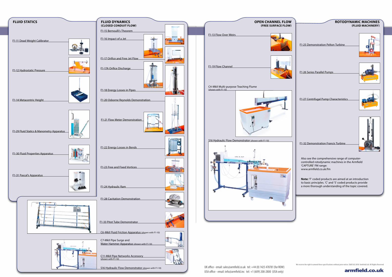
The Armfield Hydraulics Bench and accessories have long been the benchmark used in fluid mechanics teaching laboratories. The comprehensive range of equipment covers all aspects of the teaching of hydraulics in a safe, visual and easy-to understand way, backed up by first-class teaching materials.
This range of equipment has now been extended and reinforced with an integrated range of hydrostatics teaching accessories together with some new hydraulics products. Thus the complete curriculum can be covered with this attractive range of products.
S TAT I C S | DY N A M I C S | O PE N/C LO S E D C H A N N E L FLOW | R O TO DY N A M I C S | H Y D R AU L I C S
F SERIES: BASIC FLUID MECHANICSComplete Fluid Mechanics Laboratory – F1
F1-12 Hydrostatic Pressure
F1-14 Metacentric Height
Also see the comprehensive range of computer-controlled rotodynamic machines in the Armfield ‘CAPTURE’ FM range: www.armfield.co.uk/fm
Note: ‘F’ coded products are aimed at an introduction to basic principles. ‘C’ and ‘S’ coded products provide a more thorough understanding of the topic covered.
OPEN CHANNEL FLOW (FREE SURFACE FLOW)
ROTODYNAMIC MACHINES (FLUID MACHINERY)
FLUID STATICS
F1-11 Dead Weight Calibrator
F1-29 Fluid Statics & Manometry Apparatus
F1-31 Pascal's Apparatus
F1-30 Fluid Properties Apparatus
F1-15 Bernoulli’s Theorem
F1-16 Impact of a Jet
F1-17 Orifice and Free Jet Flow
F1-17A Orifice Discharge
F1-18 Energy Losses in Pipes
F1-20 Osborne Reynolds Demonstration
F1-21 Flow Meter Demonstration
F1-22 Energy Losses in Bends
F1-23 Free and Fixed Vortices
F1-24 Hydraulic Ram
F1-28 Cavitation Demonstration
C6-MkII Fluid Friction Apparatus (shown with F1-10)S16 Hydraulic Flow Demonstrator (shown with F1-10)
S16 Hydraulic Flow Demonstrator (shown with F1-10)
C7-MkII Pipe Surge and Water Hammer Apparatus (shown with F1-10)
C11-MkII Pipe Networks Accessory (shown with F1-10)
F1-13 Flow Over Weirs
F1-19 Flow Channel
S16 Hydraulic Flow Demonstrator (shown with F1-10)F1-32 Demonstration Francis Turbine
F1-25 Demonstration Pelton Turbine
F1-26 Series Parallel Pumps
F1-27 Centrifugal Pump Characteristics
C4-MkII Multi-purpose Teaching Flume(shown with F1-10)
FLUID DYNAMICS (CLOSED CONDUIT FLOW)
© Armfield Ltd. 2016
F1-33 Pitot Tube Demonstrator
UK office - email: [email protected] tel: +44 (0) 1425 478781 (for ROW)USA office - email: [email protected] tel: +1 (609) 208-2800 (USA only) armfield.co.uk
We reserve the right to amend these specif ications without prior notice. E&OE © 2018 Armfield Ltd. All Rights Reserved

F1-10-2 Basic Hydraulics Bench Digital Flow meter fitted
Service pump characteristics curve (indicative) F1-11 Dead Weight Pressure Gauge Calibrator F1-12 Hydrostatic Pressure
F1-10-1 Aftermarket Optional Fitted Digital Flow Meter
Optional Factory Fitted Digital Flow Meter
This calibrator functions on the same principle adopted in calibrating industrial pressure gauges.
DEMONSTRATION CAPABILITIES
> Calibrating a Bourdon-type pressure gauge
DESCRIPTION
The Dead Weight Pressure Gauge Calibrator consists of a precision-machined piston and cylinder assembly mounted on levelling screws.
A Bourdon gauge is supplied for calibration. The weights supplied are added to the upper end of the piston rod, which is rotated to minimise friction effects.
The gauge is thus subject to known pressures, which may be compared with the gauge readings and an error curve drawn.
TECHNICAL DETAILS
Overall dimensions: Height: 0.50m Width: 0.25m Depth: 0.125m
Pressure gauge: Bourdon tube range 0 to 200 kN/m2 (kPa)
Area of piston: 244.8 x 10⁻⁶ m2
Mass of piston: 0.5kg
Ancillary masses: 2x 0.5kg, 1.0kg and 2.5kg
The Hydrostatic Pressure accessory has been designed to determine the static thrust exerted by a fluid on a submerged surface and enables comparison of the measured magnitude and position of this force with simple theory.
DEMONSTRATION CAPABILITIES
> Determining the centre of pressure on both a submerged or partially submerged plane surface and comparison with the theoretical position
DESCRIPTION
A fabricated quadrant is mounted on a balance arm, which pivots on knife edges. The knife edges coincide with the centre of the arc of the quadrant. This means that when the quadrant is immersed, the only force that gives rise to a moment about the knife edges is the hydrostatic force acting on the end face of the quadrant.The balance arm incorporates a hanger for the weights supplied and an adjustable counterbalance.This assembly is mounted on top of an acrylic tank, which may be levelled by adjusting screwed feet. Correct alignment is indicated on a circular spirit level mounted on the base of the tank.An indicator attached to the side of the tank shows when the balance arm is horizontal. Water is added to the tank via a flexible tube and may be drained through a valve in the side of the tank. The water level is indicated on a scale on the side of the quadrant.
TECHNICAL DETAILS
Overall dimensions: Height: 0.30m – Width: 0.435m – Depth: 0.13m
Tank capacity: 5.5l
Distance between suspended mass and fulcrum: 275mm
Cross-sectional area of quadrant (toroid): 7.5 x 10⁻³m2
Total depth of completely immersed quadrant: 160mm
Height of fulcrum above quadrant: 100mm
TECHNICAL DETAILS Pump: Centrifugal type
Max head 21m H2O Max flow 1.35 l/s
Motor rating: 0.37kW
Sump tank capacity: 250l
High flow volumetric tank: 40l
Low flow volumetric tank: 6l
Height of working surface: 1m above floor level
OVERALL DIMENSIONS
Height: 1.00m Width: 1.13m Depth: 0.73m
SHIPPING SPECIFICATION
Volume: 1.5m3 Gross weight: 160kg
Individual accessories on request
SERVICES REQUIRED
Electrical supply: F1-10-A: 220-240V / 1ph / 50Hz @ 10 amp
F1-10-B: 110-120V / 1ph / 60Hz @ 20 amp
F1-10-G: 220V / 1ph / 60Hz @ 10 amp
F1-10-2-A 220-240V / 1ph / 50Hz @ 10 amp
F1-10-2-B 110-120V / 1ph / 60Hz @ 20 amp
F1-10-2-G 220V / 1ph / 60Hz @ 10 amp
Water: Fill with clean water. No permanent connection required.
F1-11 DEAD WEIGHT PRESSURE GAUGE CALIBRATOR F1-12 HYDROSTATIC PRESSURETHE F1-10 BASIC HYDRAULICS BENCH
22
20
18
16
14
12
10
8
6
4
2
00 0.1 0.2 0.3 0.4 0.5 0.6 0.7 0.8 0.9 1.0 1.1 1.2 1.3 1.4
Hea
d (m
etre
s of
wat
er)
Flow (litres S
-1)
120
100
80
60
40
20
00 20 40 60 80 100 120
Calib
rate
d pr
essu
re k
N/m
2
Indicated pressure kN/m
3
0 500MASS (g)
FULLY SUBMERGED PLATE ONLY
PARTIALLY SUBMERGED BELOW THIS POINT
r (m
m)
200
0
Graph plotting r against mass using F1-12 (indicative)
DESCRIPTION
This unit is designed as a portable and self-contained service module for a range of accessories.
The bench is constructed from lightweight corrosion-resistant plastic and is mounted on wheels for mobility. The benchtop incorporates an open channel with side channels to support the accessory on test.
Volumetric measurement is integral and has been chosen in preference to other methods of flow measurement for its ease of use, accuracy and safety – there are no heavy weights for students to handle.
The volumetric measuring tank is stepped to accommodate low or high flow rates. A stilling baffle reduces turbulence and a remote sight tube with scale gives an instantaneous indication of water level. A measuring cylinder is included in the supply for measurement of very small flow rates.
A dump valve in the base of the volumetric tank is operated by a remote actuator. Opening the dump valve returns the measured volume of water to the sump in the base of the bench for recycling. An overflow in the volumetric tank avoids flooding.
Water is drawn from the sump tank by a centrifugal pump, and a panel-mounted control valve regulates the flow. An easy-to-use quick-release pipe connector situated in the benchtop enables rapid exchange of accessories without the need for hand tools.
Each accessory is supplied as a complete piece of equipment, needing no additional service items other than the Hydraulics Bench. When coupled to the bench they are immediately ready for use.
UK office - email: [email protected] tel: +44 (0) 1425 478781 (for ROW)USA office - email: [email protected] tel: +1 (609) 208-2800 (USA only) armfield.co.uk
We reserve the right to amend these specif ications without prior notice. E&OE © 2018 Armfield Ltd. All Rights Reserved

F1-15 Bernoulli’s Theorem Demonstration F1-16 Impact of a JetF1-13 Flow Over Weirs - V notch weir F1–14 Metacentric Height
REQUIRES F1-10
REQUIRES F1-10
REQUIRES F1-10
H 5/2 (m
5/2)
(x10 -4 m
3/s)
FLOW
RAT
E
0
5.0
0 0.001 H 3/2 (m
3/2)
(x10 -3 m
3/s)
FLOW
RAT
E
0
1.5
0 0.03
Typical results obtained using F1-13 V notch weir (left) and rectangular weir
Two different weir plates are provided enabling familiarisation and comparison with theory.
DEMONSTRATION CAPABILITIES
> Demonstrating the characteristics of flow over a rectangular notch
> Demonstrating the characteristics of flow over a V notch
> Determining the coefficient of discharge
DESCRIPTION
The Flow Over Weirs consists of five basic elements used in conjunction with the flow channel in the moulded benchtop of the Hydraulics Bench.
A quick-release connector in the base of the channel is unscrewed and a delivery nozzle screwed in its place.
A stilling baffle locates into slots in the walls of the channel. The combination of the inlet nozzle and stilling baffle promote smooth flow conditions in the channel.
A Vernier hook and point gauge is mounted on an instrument carrier, which is located on the side channels of the moulded top. The carrier may be moved along the channels to the required measurement position.The rectangular notch weir or V notch weir to be tested is clamped to the weir carrier in the channel by thumb nuts. The stainless steel weir plates incorporate captive studs to aid assembly.
TECHNICAL DETAILS
Overall dimensions of weir plates: Height: 0.16m Width: 0.23m Thickness: 0.002m
Dimensions of rectangular notch: Height: 0.082m Width: 0.03m
Angle of V notch weir: 90° inclusiveHook & point gauge range: 0-150mm Accuracy: 0.1mmRequires Hydraulics Bench Service unit F1-10
This equipment enables a thorough investigation of the factors affecting the stability of a floating body.
DEMONSTRATION CAPABILITIES
> Determining the centre of gravity of the pontoon
> Determining the metacentric height and from this the position of the metacentre for the pontoon
> Varying the metacentric height with angle of heel
DESCRIPTION
The position of the metacentre can be varied to produce stable and unstable equilibrium.
The equipment consists of a plastic rectangular floating pontoon, whose centre of gravity can be varied by an adjustable weight, which slides and can be clamped in any position on a vertical mast.
A single plumb-bob is suspended from the mast, which indicates the angle of heel on a calibrated scale.
A weight with lateral adjustment enables the degree of heel to be varied and hence the stability of the pontoon determined.
The equipment does not require a separate water tank as it may be used on the Hydraulics Bench by filling the volumetric tank.
TECHNICAL DETAILS
Overall dimensions: Height: 0.475m Width: 0.35m Depth: 0.20m
Max angle of heel: ±13°
Corresponding linear dimension: ±90mm
This accessory demonstrates the application of Bernoulli’s Theorem and circumstances where it does not apply.
DEMONSTRATION CAPABILITIES
> Demonstrating Bernoulli’s Theorem and its limitations
> Directly measuring the static and total head distribution along a Venturi tube
> Determining the meter coefficient at various flow rates
DESCRIPTION
The test section consists of a classical Venturi machined in clear acrylic. A series of wall tappings enable measurement of the static pressure distribution along the converging and diverging duct. A total head tube is provided to traverse along the centre line of the test section. These tappings are connected to a manometer bank incorporating a manifold with an air bleed valve.
Pressurisation of the manometers is facilitated by a hand pump. The test section is arranged so that the characteristics of flow through both a converging and diverging section can be studied. Water is fed through a hose connector and is controlled by a flow regulator valve at the outlet of the test section.
The Venturi can be demonstrated as a means of flow measurement and the discharge coefficient can be determined.
TECHNICAL DETAILS
Overall dimensions: Height: 0.60m Width: 0.55m Depth: 0.25m
Manometer range: 0-300mm
Number of manometer tubes: 8
Throat diameter: 10.0mm
Upstream diameter: 25.0mm
Upstream taper: 14°
Downstream taper: 21°
Requires Hydraulics Bench Service unit F1-10
This equipment enables the force developed by a jet of water impinging upon a stationary object to be measured.
MEASUREMENT CAPABILITIES
> Measuring the force exerted on different targets and comparison with the forces predicted by momentum theory
DESCRIPTION
The apparatus consists of a cylindrical clear acrylic fabrication with provision for levelling. Water is fed through a nozzle and discharged vertically to strike a target carried on a stem, which extends through the cover. A weight carrier is mounted on the upper end of the stem.
The dead weight of the moving parts is counterbalanced by a compression spring. The vertical force exerted on the target plate is measured by adding the weights supplied to the weight pan until the mark on the weight pan corresponds with the level gauge.
A total of four targets are provided.
TECHNICAL DETAILS
Overall dimensions: Height: 0.50m Width: 0.325m Depth: 0.20m
Nozzle diameter: 8mm
Distance between nozzle & target plate: 20mm
Diameter of target plate: 36mm
Target plates: – 180° hemispherical target – 120° target (cone) – flat target – 30° target
Requires Hydraulics Bench Service unit F1-10
F1-15 BERNOULLI’S THEOREM DEMONSTRATION F1-16 IMPACT OF A JETF1-13 FLOW OVER WEIRS F1-14 METACENTRIC HEIGHT
UK office - email: [email protected] tel: +44 (0) 1425 478781 (for ROW)USA office - email: [email protected] tel: +1 (609) 208-2800 (USA only) armfield.co.uk
We reserve the right to amend these specif ications without prior notice. E&OE © 2018 Armfield Ltd. All Rights Reserved

F1-18 Energy Losses in PipesF1-17 Orifice and Free Jet Flow F1-19 Flow ChannelF1-17a Orifice Discharge
REQUIRES F1-10
REQUIRES F1-10
REQUIRES F1-10
REQUIRES F1-10
This equipment permits calibration of two orifices of differing diameter and enables the trajectory of the jet to be plotted.
MEASUREMENT CAPABILITIES
> Establishing the coefficient of velocity for a small orifice
> Finding the coefficient of discharge for a small orifice with flow under constant head and flow under varying head
> Comparing the measured trajectory of a jet with that predicted by simple theory of mechanics
DESCRIPTION
In the Orifice & Free Jet Flow accessory a constant head tank is fed with water from the Hydraulics Bench. The orifice is installed at the base of this tank by means of a special wall fitting, which provides a flush inside surface.
The head is maintained at a constant value by an adjustable overflow and is indicated by a level scale. A series of adjustable probes enable the path followed by the jet to be ascertained.
Adjustable feet permit levelling.
TECHNICAL DETAILS
Overall dimensions: Height: 0.60m Width: 0.67m Depth: 0.33m
Orifice diameters: 3.0mm and 6.0mm
Jet trajectory probes: 8
Max constant head: 410mmRequires Hydraulics Bench Service unit F1-10
The Orifice Discharge accessory enables full analysis of the flow through five different orifices over a range of flow rates.
MEASUREMENT CAPABILITIES
> Determining the contraction and velocity coefficients
> Calculating the discharge coefficient
DESCRIPTION
The Orifice Discharge accessory consists of a cylindrical clear acrylic tank, which has an orifice fitted in the base.
A traverse assembly is provided, which enables a pitot tube to be positioned anywhere in the jet. Attached to this pitot tube is a fine wire, which can be traversed across the jet to accurately measure the jet diameter and the vena contracta diameter and so determine the contraction coefficient. The pitot head and the total head across the orifice are shown on manometer tubes adjacent to the tank.
In addition to the sharp edged orifice, four additional orifices with different profiles are supplied. All orifices have a common bore of 13mm for direct comparison of performance.
TECHNICAL DETAILS
Overall dimensions: Height: 0.60m Width: 0.33m Depth: 0.33m
Standard orifice: Sharp-edged 13mm diameter
Max head: 365mm
Traverse mechanism: Lead screw with adjusting nut Calibrated 0.1mm per division
Requires Hydraulics Bench Service unit F1-10
This equipment enables the pressure drop of water passing through a hydraulically smooth circular pipe to be measured in detail and the pipe friction equation to be verified.
DEMONSTRATION CAPABILITIES
> Investigating the variation of friction head along a circular pipe with the mean flow velocity in the pipe
> Investigating the effects of laminar and turbulent flow regimes
DESCRIPTION
The Energy Losses in Pipes accessory consists of a test pipe, orientated vertically on the side of the equipment, which may be fed directly from the Hydraulics Bench supply or, alternatively, from the integral constant head tank.
These sources provide high or low flow rates which may be controlled by a valve at the discharge end of the test pipe. Head loss between two tapping points in the test pipe is measured using two manometers, a water over mercury manometer for large pressure differentials and a pressurised water manometer for small pressure differentials.
Excess water discharging from the constant head tank is returned to the sump tank of the Hydraulics Bench. Adjustable feet permit levelling.
Mercury is not supplied.
The H12-8 Digital Pressure Meter is available as an alternative to mercury manometers – for more information view online: www.armfield.co.uk/h12-8
TECHNICAL DETAILS
Overall dimensions: Height: 0.75m Width: 0.28m Depth: 0.33m
Diameter of test pipe: 3.0mm
Length of test pipe: 760mm
Distance between pressure tapping points: 500mm
Range of mercury manometer: 500mm
Range of water manometer: 500mm
Measuring cylinder capacity: 1000ml
Requires Hydraulics Bench Service unit F1-10
The Flow Channel introduces students to the characteristics of flow in an open channel at an elementary level.
DEMONSTRATION & VISUALISATION CAPABILITIES
> Demonstrating basic phenomena associated with open channel flow
> Visualisation of flow patterns over or around immersed objects
DESCRIPTION
The channel consists of a clear acrylic working section of large depth-to-width ratio incorporating undershot and overshot weirs at the inlet and discharge ends respectively. Water is fed to the streamlined channel entry via a stilling tank to reduce turbulence. Water discharging from the channel is collected in the volumetric tank of the Hydraulics Bench and returned to the sump for recirculation. A dye injection system incorporated at the inlet to the channel enables flow visualisation in conjunction with a graticule on the rear face of the channel.
Models supplied with the channel include broad and sharp-crested weirs, large and small-diameter cylinders and symmetrical and asymmetrical aerofoils, which in conjunction with the inlet and discharge weirs, permit a varied range of open channel and flow visualisation demonstrations.
Adjustable feet permit levelling.
TECHNICAL DETAILS
Overall dimensions: Height: 0.50m Width: 0.865m Depth: 0.33m
Dye injection needles: 5
Dye reservoir capacity: 0.45l
Width of channel: 15mm
Length of channel: 615mm
Depth of channel: 150mm
Models: – broad-crested weir – narrow-crested weir – symmetrical aerofoil – asymmetrical aerofoil – small cylinder – large cylinder
Requires Hydraulics Bench Service unit F1-10
F1-18 ENERGY LOSSES IN PIPES F1-19 FLOW CHANNELF1-17 ORIFICE AND FREE JET FLOW F1-17A ORIFICE DISCHARGE
UK office - email: [email protected] tel: +44 (0) 1425 478781 (for ROW)USA office - email: [email protected] tel: +1 (609) 208-2800 (USA only) armfield.co.uk
We reserve the right to amend these specif ications without prior notice. E&OE © 2018 Armfield Ltd. All Rights Reserved

Typical results obtained using F1–21 orifice plate
F1-23 Free and Forced VorticesF1-22 Energy Losses in Bends F1-20 Osborne Reynolds’ Demonstration F1-21 Flow Meter Demonstration
REQUIRES F1-10
REQUIRES F1-10
REQUIRES F1-10
REQUIRES F1-10
7.0
00 0.7
Flow
Rat
e
H /12
(x10 -4 m 3/s)
(m ) /12
7.0
00 0.7
Flow
Rat
e
H /12
(x10 -4 m 3/s)
(m ) /12This item is intended to reproduce the classic experiments
conducted by Professor Osborne Reynolds concerning the nature of laminar and turbulent flow.
DEMONSTRATION CAPABILITIES
> Reproducing the classic experiments conducted by Professor Osborne Reynolds concerning fluid flow condition
> Observing the laminar, transitional, turbulent flow and velocity profile
DESCRIPTION
The equipment operates in a vertical orientation. A header tank containing stilling media provides a constant head of water through a bellmouth entry to the flow visualisation pipe. Flow through this pipe is regulated using a control valve at the discharge end. The flow rate of water through the pipe can be measured using the volumetric tank (or measuring cylinder) of the Hydraulics Bench. Velocity of the water can therefore be determined to enable calculation of Reynolds’ number.
The equipment uses a similar dye injection technique to that of Reynolds’ original apparatus to enable observation of flow conditions.
TECHNICAL DETAILS
Overall dimensions: Height: 1.24m Width: 0.50m Depth: 0.33m
Test pipe diameter: 10.0mm (precision bore glass)
Length of test pipe: 700mm
Dye reservoir capacity: 0.45lRequires Hydraulics Bench Service unit F1-10
This accessory is designed to introduce students to three basic types of flow meter.
DEMONSTRATION CAPABILITIES
> Directly comparing flow measurement using a Venturi meter, variable area meter and orifice plate
> Calibrating each flow meter using the volumetric measuring tank of the bench
> Comparing pressure drops across each device
DESCRIPTION
The equipment consists of a Venturi meter, variable area meter and orifice plate, installed in a series configuration to permit direct comparison. A flow control valve permits variation of the flow rate through the circuit. Pressure tappings are incorporated so that the head loss characteristics of each flow meter may be measured. These tappings are connected to an eight-tube manometer bank incorporating a manifold with an air bleed valve.
Pressurisation of the manometers is facilitated by a hand pump. The circuit and manometer are attached to a support framework, which stands on the working top of the Hydraulics Bench. The bench is used as the source of water supply and for volumetrically calibrating each flow meter.
TECHNICAL DETAILS
Overall dimensions: Height: 0.83m Width: 0.68m Depth: 0.33m
Manometer range: 0-400mm
Number of manometer tubes: 8
Orifice plate diameter: 20mm
Variable area meter: 2-20 l/min
Venturi dimensions: – Throat diameter: 15mm
– Upstream pipe diameter: 31.75mm – Upstream taper: 21° inclusive – Downstream taper: 14° inclusive
Requires Hydraulics Bench Service unit F1-10
This accessory permits losses in different bends, a sudden contraction, sudden enlargement and a typical control valve to be demonstrated.
DEMONSTRATION & MEASUREMENT CAPABILITIES
> Measuring the losses in the devices related to flow rate and calculating loss coefficients related to velocity head
> Comparing the pressure drop across each device
DESCRIPTION
The equipment is mounted on a free-standing framework, which supports the test pipework and instrumentation. The following typical pipe fittings are incorporated for study: mitre bend, 90° elbow, swept bends (large and small radius), sudden contraction and sudden enlargement. All are instrumented with upstream and downstream pressure tappings. These tappings are connected to a bank of 12 water manometer tubes, mounted on the framework. Pressurisation of the manometers is facilitated by a hand pump. A gate valve is used to control the flow rate.
A separate gate valve is instrumented with upstream and downstream pressure tappings, which are connected to a differential gauge on the edge of the framework. The unit stands on the working top of the Hydraulics Bench, which is also used as the source of water supply.
TECHNICAL DETAILS
Overall dimensions: Height: 0.83m Width: 0.63m Depth: 0.33m
Pipe diameter: 19.48mm
Differential pressure gauge: 0-3 bar
Enlargement diameter: 26.2mm
Contraction diameter: 19.48mm
Fittings: – 45° mitre – elbow – short bend – large bend – enlargement – contraction
Manometer range: 0-440mm
Number of manometer tubes: 12
Differential manometers: 6
Requires Hydraulics Bench Service unit F1-10
This equipment is designed to produce and measure the characteristics of free and forced vortices.
MEASUREMENT & VISUALISATION CAPABILITIES
> Understanding the difference between free and forced vortices
> Determining the surface profile of a forced vortex
> Determining the surface profile and total head distribution of a free vortex
> Visualisation of secondary flow in a free vortex
DESCRIPTION
The apparatus comprises a clear acrylic cylinder on a plinth designed to produce and measure free and forced vortices. The free vortex is generated by water discharging through an interchangeable orifice in the base of the cylinder, and the resulting profile is measured using a combined calliper and depth scale. The forced vortex is induced by a paddle in the base of the cylinder, which is rotated by jets of water. The profile of the forced vortex is determined using a series of depth gauges.
Velocity at any point in the free or forced vortices may be measured using the appropriate pitot tube supplied. Dye crystals (not supplied) may be used to demonstrate secondary flow at the base of the free vortex.
TECHNICAL DETAILS
Overall dimensions: Height: 0.46m Width: 0.60m Depth: 0.50m
Tank diameter: 245mm
Height to overflow point: 180mm
Orifice diameters: 8, 16 and 24mm
Forced vortex measuring probes
Distance from centre: 0, 30, 50, 70, 90 and 110mm
Pitot tubes having measuring point (nose) at: 15, 25 and 30mm radius
Inlet tubes: 9 and 12.5mm diameterRequires Hydraulics Bench Service unit F1-10
F1-22 ENERGY LOSSES IN BENDS F1-23 FREE AND FORCED VORTICESF1-20 OSBORNE REYNOLDS’ DEMONSTRATION F1-21 FLOW METER DEMONSTRATION
UK office - email: [email protected] tel: +44 (0) 1425 478781 (for ROW)USA office - email: [email protected] tel: +1 (609) 208-2800 (USA only) armfield.co.uk
We reserve the right to amend these specif ications without prior notice. E&OE © 2018 Armfield Ltd. All Rights Reserved

F1-26 Series/Parallel Pumps F1-27 Centrifugal Pump CharacteristicsF1-25 Demonstration Pelton TurbineF1-24 Hydraulic Ram
REQUIRES F1-10
REQUIRES F1-10
REQUIRES F1-10
REQUIRES F1-10
REQUIRES F1-10
If flowing water is suddenly brought to rest in a long pipe, a phenomena known as water hammer occurs, wherein a pressure wave travels along the pipe. This principle is used in the hydraulic ram to pump water.
DEMONSTRATION CAPABILITIES
> Establishing flow/pressure characteristics and determining efficiency of the hydraulic ram
DESCRIPTION
The Hydraulic Ram comprises an acrylic base incorporating pulse and non-return valves and a supply reservoir on a stand, which is fed by the Hydraulics Bench. An air vessel above the valve chamber smooths cyclic fluctuations from the ram delivery.
The weights supplied may be applied to the pulse valve to change the closing pressure and thus the operating characteristics.
TECHNICAL DETAILS
Overall dimensions: Height: 1.62m Width: 0.75m Depth: 0.33m
Supply head: 300-700mm variable
Delivery head: 750-1500mm variableRequires Hydraulics Bench Service unit F1-10
The Demonstration Pelton Turbine provides a simple low-cost introduction to turbine performance.
DEMONSTRATION CAPABILITIES
> Determining the operating characteristics, ie power, efficiency and torque, of a Pelton turbine at various speeds
DESCRIPTION
This accessory comprises a miniature Pelton wheel with spear-valve arrangement mounted on a support frame, which fits on to the Hydraulics Bench top channel. Mechanical output from the turbine is absorbed using a simple friction dynamometer.
Pressure at the spear valve is indicated on a remote gauge. A non-contacting tachometer (not supplied) may be used to determine the speed of the Pelton wheel.
Basic principles of the Pelton turbine may be demonstrated and, with appropriate measurements, power produced and efficiency may be determined.
TECHNICAL DETAILS
Overall dimensions: Height: 0.60m Width: 0.40m Depth: 0.30m
Speed range: 0-2000 rpm
Brake power: 10W
Pressure gauge range: 0-25m H2O
Force balance range: 0-20N + 0.2N
Number of Pelton buckets: 16
Diameter of Pelton wheel: 123mmRequires Hydraulics Bench Service unit F1-10
The introduction of a second pump to the Hydraulic Bench system enables the study of two pump performance, both in series and parallel operation.
MEASUREMENT CAPABILITIES
Determining the head/flow rate characteristics of:
> A single centrifugal pump at a single speed
> Two similar pumps operating in a parallel configuration at the same speed
> Two similar pumps operating in a series configuration at the same speed
DESCRIPTION
This accessory comprises a fixed-speed pump assembly and independent discharge manifold interconnected by flexible tubing with quick-release connectors. This auxiliary pump is intended to be used in conjunction with the basic Hydraulics Bench.
The auxiliary pump is mounted on a support plinth, which stands adjacent to the Hydraulics Bench primary pump.
TECHNICAL DETAILS
Overall dimensions: Height: 0.50m Width: 0.25m Depth: 0.55m
Pump: Centrifugal type Max head 21m H
2O
Max flow 1.35 l/s
Motor rating: 0.36kW
Pressure gauge range: 0-60m H2O
Compound gauge range: –10 to +32m H2O
See Hydraulics Bench F1-10 technical details for primary pump characteristics.
SERVICES REQUIRED
Electrical supply: F1-26-A: 220-240V / 1ph / 50Hz @ 10 amp F1-26-B: 110-120V / 1ph / 60Hz @ 20 amp F1-26-G: 220V / 1ph / 60Hz @ 10 ampRequires Hydraulics Bench Service unit F1-10
This accessory offers similar features to the F1-26, but with enhanced capabilities provided by the inclusion of a variable-speed pump with inverter drive rather than a fixed-speed pump.
MEASUREMENT CAPABILITIES
> Determining the relationship between head, discharge, speed, power and efficiency for a centrifugal pump at various speeds
> Determining the head/flow rate characteristics of two similar pumps operating in either parallel or series configuration at the same speed
DESCRIPTION
This accessory comprises a variable-speed pump assembly and independent discharge manifold interconnected by flexible tubing with quick release connectors. This auxiliary pump is intended to be used in conjunction with the basic Hydraulics Bench. The auxiliary pump is mounted on a support plinth, which stands adjacent to the Hydraulics Bench's primary pump, with which it is intended to be used.The pump speed is varied by an inverter drive. The motor speed, output voltage and motor current can be monitored on the inverter display. A compound pressure gauge is mounted on the pump inlet and a pressure gauge is mounted on the pump outlet.An independent discharge manifold incorporates a pressure gauge and flow control valve prior to a discharge pipe with diffuser.
TECHNICAL DETAILS
Overall dimensions: Height: 0.325m – Width: 0.16m – Depth: 0.36m
Pump: Centrifugal type Max head 21.0m H
2O
Max flow rate 1.35 l/s
Motor: 0.36kW
Speed controller: Frequency inverter
Speed range: 0-1500 rpm
Pressure gauge: 0-60m H2O
Compound gauge: -10 to +32m H2O
See Hydraulics Bench F1-10 technical details for primary pump characteristics.
SERVICES REQUIRED
Electrical supply: F1-27-A: 220-240V / 1ph / 50Hz @ 10 amp F1-27-G: 220V / 1ph / 60Hz @ 10 amp G version has optional 1.5kVA transformer available to accommodate 120V / 1ph / 60Hz. Requires Hydraulics Bench Service unit F1-10
F1-26 SERIES/PARALLEL PUMPS F1-27 CENTRIFUGAL PUMP CHARACTERISTICSF1-24 HYDRAULIC RAM F1-25 DEMONSTRATION PELTON TURBINE
UK office - email: [email protected] tel: +44 (0) 1425 478781 (for ROW)USA office - email: [email protected] tel: +1 (609) 208-2800 (USA only) armfield.co.uk
We reserve the right to amend these specif ications without prior notice. E&OE © 2018 Armfield Ltd. All Rights Reserved

F1-29 Fluid Statics and ManometryF1-28 Cavitation Demonstration
REQUIRES F1-10
This accessory visually, audibly and numerically demonstrates the phenomenon of cavitation and its association with the vapour pressure of a liquid.
DEMONSTRATION CAPABILITIES
> Observation of the phenomenon of cavitation in a liquid (by reducing the liquid to its vapour pressure)
> Comparison of theoretical and actual pressure at cavitation conditions
> Observation of air-release due to dissolved gases in a liquid
> Demonstration of reducing cavitation by increasing the static pressure in a liquid
DESCRIPTION
This accessory consists of a circular Venturi-shaped test section manufactured from clear acrylic to enable visualisation inside the section. As the flow of water increases the pressure at the throat falls in accordance with the Bernoulli equation until a limit is reached corresponding to the vapour pressure of the liquid. At this low pressure small bubbles of vapour form then collapse violently as the pressure rises again downstream – a process called cavitation.
Bourdon gauges indicate the pressure upstream of the contraction, inside the throat and downstream of the expansion in the test section. Flow control valves upstream and downstream of the test section enable the flow and pressure to be adjusted, enabling cavitation to be clearly demonstrated.
TECHNICAL DETAILS
Overall dimensions: Height: 0.30m Width: 0.30m Depth: 0.15m
Upstream pressure gauge: Diameter: 63mm Range: 0 to 1 bar
Throat vacuum gauge: Diameter: 100mm Range: -1 to 0 bar
Downstream pressure gauge: Diameter: 63mm Range: 0 to -1 bar
Requires Hydraulics Bench Service unit F1-10
This apparatus provides an introduction to the behaviour of liquids under hydrostatic conditions (fluid at rest) and the application of these principles to pressure measurement using manometers.
MEASUREMENT CAPABILITIES
> Demonstrating the behaviour of liquids at rest (hydrostatics)
> Showing that the free surface of a liquid is horizontal and independent of cross section
> Measuring liquid level using a scale and the effect of parallax
> Measuring small changes in liquid level using a micro-manometer
> Measuring changes in liquid level using a Vernier hook and point gauge
> Using a single piezometer / manometer tube to measure head
> Using manometer tubes to measure differential pressure
> Using an inclined manometer to measure small pressure differences
> Using a ‘U’ tube manometer to measure pressure differences in a gas (air over liquid)
> Using an inverted pressurised ‘U’ tube manometer to measure pressure differences in a liquid
> Using liquids with different densities to change the sensitivity of a ‘U’ tube manometer
> Demonstrating the effect of trapped air on the accuracy of a
manometer
> Demonstrating the effect of flowing liquid (friction in a fluid created
by motion)
DESCRIPTION
The Armfield F1-29 is designed to demonstrate the properties of Newtonian fluids and their behaviour under hydrostatic conditions (fluid at rest). This enables students to develop an understanding and knowledge of a wide range of fundamental principles and techniques, before studying fluids in motion. These include the use of fluids in manometers to measure pressure and pressure differences in gases and liquids.Some simple exercises are included to show how the behaviour of a fluid changes when flow is involved and the relevance of concepts such as frictional losses.The apparatus is constructed from PVC and clear acrylic, and consists of a vertical reservoir containing water that is connected to a series of vertical manometer tubes. These tubes can be used individually or in combination for the different demonstrations of hydrostatic principles and manometry. One tube includes changes in cross section to demonstrate that the level of a free surface is not affected by the size or the shape of the tube. The right-hand manometer tube is separate from the other tubes and incorporates a pivot and indexing mechanism at the base that enables this tube to be inclined at fixed angles of 5°, 30°, 60° and 90° (vertical).The reservoir incorporates a hook and point gauge with Vernier scale, mounted through the lid, that enables large changes in level to be measured with better precision than a simple scale. A vertical transparent piezometer tube through the lid of the reservoir enables the static head above the water in the reservoir to be observed when the air space above the water is not open to atmosphere.Connections at the top of the reservoir and each of the manometer tubes enables a syringe to be connected using flexible tubing that permits the static pressure of the air to be varied positively or negatively as required for the various demonstrations. The syringe and flexible tubing for filling the equipment etc. are stored at the rear of the apparatus when not in use for convenience.A small flow can be induced through the interconnecting pipework between the various manometer tubes to provide a simple but clear demonstration of the effect of friction created by the motion of the fluid. This is useful to the student before performing demonstrations using more advanced fluid dynamics accessories.The equipment is designed to demonstrate the basic principles of hydrostatics and manometry using water for safety and convenience. The use of a safe, soluble food dye in the water makes observation of the level changes clearer without affecting the operation of the apparatus. Alternative liquids, with different densities, can be used in the ‘U’ tube manometer if required to extend the range of the demonstrations.
TECHNICAL DETAILS
Overall dimensions: Height: 1.09m Width: 0.425m Depth: 0.15m
Max depth inside reservoir: 574mm
Inside diameter of reservoir: 100mm
Scale length of manometer tubes: 460mm
Manometer tubes incorporated: 1 ‘U’ tube
2 vertical parallel tubes 1 vertical tube with varying cross section 1 vertical tube with pivot enabling operation at three different inclinations
Does not require Hydraulics Bench Service unit F1-10
F1-28 CAVITATION DEMONSTRATION F1-29 FLUID STATICS AND MANOMETRY
UK office - email: [email protected] tel: +44 (0) 1425 478781 (for ROW)USA office - email: [email protected] tel: +1 (609) 208-2800 (USA only) armfield.co.uk
We reserve the right to amend these specif ications without prior notice. E&OE © 2018 Armfield Ltd. All Rights Reserved
F1-30 Fluid Properties F1-31 Pascal's Apparatus
UK office - email: [email protected] tel: +44 (0) 1425 478781 (for ROW)USA office - email: [email protected] tel: +1 (609) 208-2800 (USA only) armfield.co.uk
We reserve the right to amend these specif ications without prior notice. E&OE © 2018 Armfield Ltd. All Rights Reserved
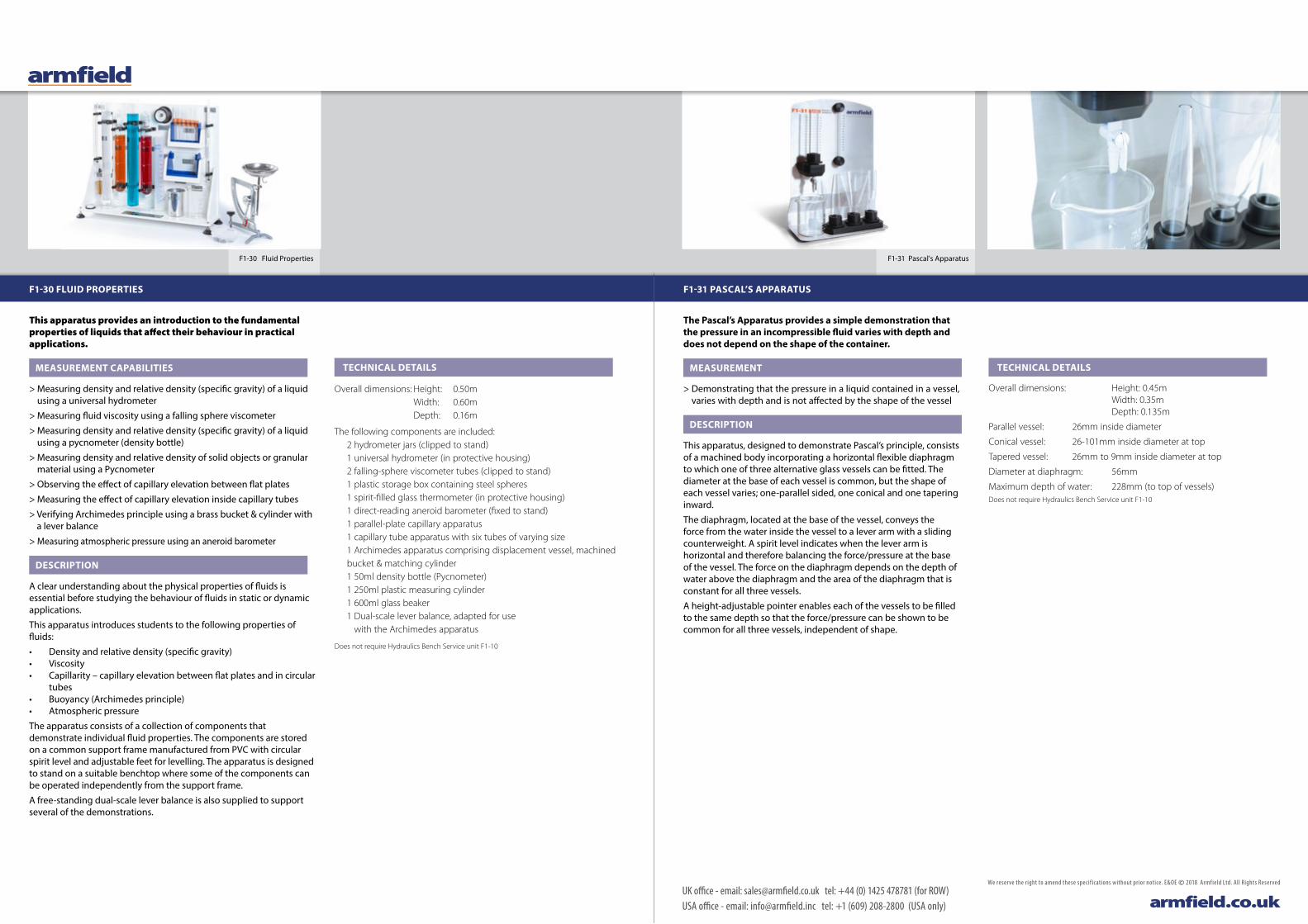
This apparatus provides an introduction to the fundamental properties of liquids that affect their behaviour in practical applications.
MEASUREMENT CAPABILITIES
> Measuring density and relative density (specific gravity) of a liquid using a universal hydrometer
> Measuring fluid viscosity using a falling sphere viscometer
> Measuring density and relative density (specific gravity) of a liquid using a pycnometer (density bottle)
> Measuring density and relative density of solid objects or granular material using a Pycnometer
> Observing the effect of capillary elevation between flat plates
> Measuring the effect of capillary elevation inside capillary tubes
> Verifying Archimedes principle using a brass bucket & cylinder with a lever balance
> Measuring atmospheric pressure using an aneroid barometer
DESCRIPTION
A clear understanding about the physical properties of fluids is essential before studying the behaviour of fluids in static or dynamic applications.
This apparatus introduces students to the following properties of fluids:
• Density and relative density (specific gravity)• Viscosity• Capillarity – capillary elevation between flat plates and in circular
tubes• Buoyancy (Archimedes principle)• Atmospheric pressure
The apparatus consists of a collection of components that demonstrate individual fluid properties. The components are stored on a common support frame manufactured from PVC with circular spirit level and adjustable feet for levelling. The apparatus is designed to stand on a suitable benchtop where some of the components can be operated independently from the support frame.
A free-standing dual-scale lever balance is also supplied to support several of the demonstrations.
The Pascal’s Apparatus provides a simple demonstration that the pressure in an incompressible fluid varies with depth and does not depend on the shape of the container.
MEASUREMENT
> Demonstrating that the pressure in a liquid contained in a vessel, varies with depth and is not affected by the shape of the vessel
DESCRIPTION
This apparatus, designed to demonstrate Pascal’s principle, consists of a machined body incorporating a horizontal flexible diaphragm to which one of three alternative glass vessels can be fitted. The diameter at the base of each vessel is common, but the shape of each vessel varies; one-parallel sided, one conical and one tapering inward.
The diaphragm, located at the base of the vessel, conveys the force from the water inside the vessel to a lever arm with a sliding counterweight. A spirit level indicates when the lever arm is horizontal and therefore balancing the force/pressure at the base of the vessel. The force on the diaphragm depends on the depth of water above the diaphragm and the area of the diaphragm that is constant for all three vessels.
A height-adjustable pointer enables each of the vessels to be filled to the same depth so that the force/pressure can be shown to be common for all three vessels, independent of shape.
TECHNICAL DETAILS
Overall dimensions: Height: 0.50m Width: 0.60m Depth: 0.16m
The following components are included: 2 hydrometer jars (clipped to stand)
1 universal hydrometer (in protective housing) 2 falling-sphere viscometer tubes (clipped to stand) 1 plastic storage box containing steel spheres 1 spirit-filled glass thermometer (in protective housing) 1 direct-reading aneroid barometer (fixed to stand) 1 parallel-plate capillary apparatus 1 capillary tube apparatus with six tubes of varying size 1 Archimedes apparatus comprising displacement vessel, machined bucket & matching cylinder 1 50ml density bottle (Pycnometer) 1 250ml plastic measuring cylinder 1 600ml glass beaker 1 Dual-scale lever balance, adapted for use
with the Archimedes apparatus
Does not require Hydraulics Bench Service unit F1-10
TECHNICAL DETAILS
Overall dimensions: Height: 0.45m Width: 0.35m Depth: 0.135m
Parallel vessel: 26mm inside diameter
Conical vessel: 26-101mm inside diameter at top
Tapered vessel: 26mm to 9mm inside diameter at top
Diameter at diaphragm: 56mm
Maximum depth of water: 228mm (to top of vessels)Does not require Hydraulics Bench Service unit F1-10
F1-30 FLUID PROPERTIES F1-31 PASCAL’S APPARATUS

F1-32 Francis Turbine F1-33 Pitot Tube Demonstrator
REQUIRES F1-10
C4-MKII Multipurpose Teaching Flume(shown with F1-10 Hydraulics Bench)
REQUIRES F1-10
Turbine detail
REQUIRES F1-10
REQUIRES F1-10
C4-MKII MULTIPURPOSE TEACHING FLUME
UK office - email: [email protected] tel: +44 (0) 1425 478781 (for ROW)USA office - email: [email protected] tel: +1 (609) 208-2800 (USA only) armfield.co.uk
We reserve the right to amend these specif ications without prior notice. E&OE © 2018 Armfield Ltd. All Rights Reserved
This demonstration turbine provides a simple low-cost introduction to the Francis inward flow reaction turbine showing its construction, operation and performance.
MEASUREMENT CAPABILITIES
> Determining the operating characteristics, ie power, efficiency and torque, of a Francis Turbine at various speeds and guide vane openings
DESCRIPTION
A tapering, spiral-shaped volute conveys water to the runner via a ring of guide vanes that are adjustable in angle to vary the flow through the turbine. Water enters the runner tangentially at the periphery, flows radially inward through the blades toward the hub then exits axially via a draft tube.
Power generated by the turbine is absorbed by a Prony friction brake consisting of a pair of spring balances attached to a brake belt that is wrapped around a pulley wheel driven by the runner. The load on the turbine is varied by tensioning both spring balances, which increases the friction on the pulley wheel. Brake force is determined from the difference in the readings on the two spring balances and the torque calculated from the product of this force and the pulley radius.
The head of water entering the turbine is indicated on a Bourdon gauge and the speed of rotation is measured using a non-contacting tachometer (not supplied).
The volute of the Francis Turbine incorporates a transparent front cover for clear visualisation of the runner and guide vanes and is designed to complement the F1-25 Pelton turbine.
TECHNICAL DETAILS
Overall dimensions: Height: 0.85m Width: 0.60m Depth: 0.34m
Speed range: 0-4000 rpm
Diameter of Francis runner: 60mm
Number of blades on runner: 12
Number of guide vanes: 6, adjustable from fully open to fully closed
Range of spring balances: 0-50N x 0.5N
Range of Bourdon gauge: 0-2 barRequires Hydraulics Bench Service unit F1-10
F1-32 FRANCIS TURBINE
Sharp Crested Weir Broad Crested Weir
Venturi flumeCrump weir
The Armfield Multipurpose Teaching Flume has been specifically designed to demonstrate the principles of fluid mechanics when applied to engineering structures in open channel flow.
EXPERIMENTAL CAPABILITIES
> Use of hook and point gauges to measure water level
> Use of a pitot static tube to measure flow rate (using optional C4-61)
> Learning how to apply force-momentum and steady-flow energy equations to simple flow situations
> Understanding the relationship between water level above the crest of a weir and flow rate over the weir
> Using hydraulic structures to control level, eg syphon spillways
> Understanding sub and super-critical flow and the underlying characteristics of standing waves
> Hydraulic jump
> Using hydraulic structures for control of flow, eg sluice gate
> Applying and understanding Manning’s formula
> Measurement of velocity profiles (using optional C4-61)
> Waves (using optional C4-67)
DESCRIPTION
The C4MkII is a small open channel flume, available in 2.5m or 5.0m lengths, with clear acrylic sides to the working section for complete visibility of the flow.
The channel is fitted with a PVC inlet tank, and is designed for free discharge into the Hydraulics Bench. The flume is mounted on a rigid framework, and can be tilted by use of a calibrated screwjack, which enables accurate slope adjustment of the channel.
The inlet tank incorporates a stilling arrangement to diffuse the water flow prior to entry into the channel, ensuring smooth uniform flow. The level in the working section of the flume is controlled using an overshot weir (stop logs) at the discharge end.
Bed-pressure tappings and fixing points for models are provided. A longitudinal scale positioned at the top of the channel enables depth gauges and pitot static tubes to be accurately positioned along the channel length.
The flume is designed for use with a standard Armfield F1-10 Hydraulics Bench, which provides the pumped water flow, the flow control valve and a volumetric tank for flow measurement.
Also available is an optional flow meter, which can be fitted to the C4-MkII to enable direct flow measurements to be taken.
Optional educational software is available (C4-MKII-301) offering a complete teaching package of coursework. The student manually enters data in the software, which can then be used for calculations, data processing and graph plotting.
Requires Hydraulics Bench Service unit F1-10
TECHNICAL DETAILS
Overall dimensions:
C4-MkII-2.5 C4-MkII-5.0 Length: 2.91m Length: 5.41m Width: 0.62m Width: 0.62m Height: 1.46m Height: 1.46m
Channel dimensions: Width: 76mm Height: 250mm Channel slope: Adjustable between -1% and +3%
Models and gauges supplied:• Venturi flume • Sharp and broad-crested weirs • Crump weir • Adjustable undershot weir • Two Vernier level gauges (Hook and point gauges)
Optional models available:
C4-61: Pitot tube and manometer
C4-62: Culvert fitting, one edge square, one rounded
C4-63: Flow splitters; central wall with various nose pieces
C4-64: Free overflow spillway section complete with ski jump, sloping apron and blended reverse curvature attachments
C4-65: Syphon spillway and air-regulated syphon
C4-66: Model radial gate
C4-67: Wave generator and wave absorbing beach
C4-68: False floor sections for gradually varied profiles
C4-69: Artificially roughened bed 2.5m-long section (two required for a 5m flume)
F1-33 PITOT TUBE DEMONSTRATOR
The pitot tube can be moved across the cross-section of the pipe in order to measure the dynamic head profile.
MEASUREMENT CAPABILITIES
> Operation of a pitot static tube and pressurised water manometer
> Velocity flow profile in a pipe
> Demonstration that the fluid velocity is proportional to the square root of the head difference between the total head and the static head
DESCRIPTION
The pitot tube can be moved across the cross-section of the pipe in order to measure the dynamic head profile. The position of the measuring tip relative to the wall of the pipe can be read on a scale. The pitot tube is connected to a pressurised water manometer to measure the differential head across the pitot static tube.
The F1-33 is designed for use with the Armfield F1-10 Hydraulics Bench and includes compatible connecting tubes.
No additional instrumentation is required to operate the F1-33.
TECHNICAL DETAILS
Overall dimensions: Height: 0.52m Width: 1.00m Depth: 0.35m
Net weight: 6kg
Water supply: From Basic Hydraulics Bench
Requires Hydraulics Bench Service unit F1-10
C6MkII-10 Fluid Friction Apparatus C6MkII-10 with F10 Bench
REQUIRES F1-10
C7MkII shown with F1-10
REQUIRES F1-10
REQUIRES F1-10
REQUIRES F1-10
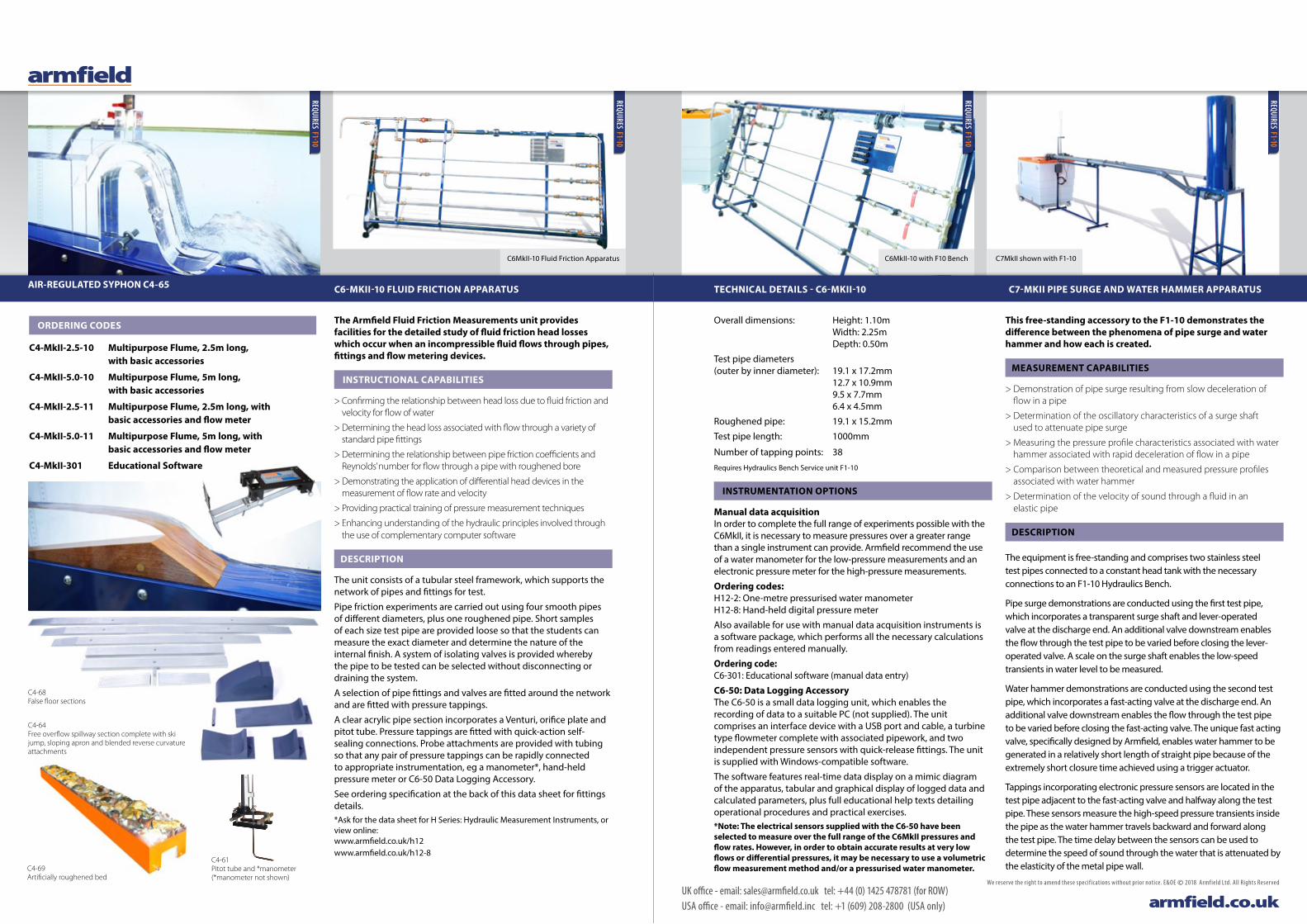
This free-standing accessory to the F1-10 demonstrates the difference between the phenomena of pipe surge and water hammer and how each is created.
MEASUREMENT CAPABILITIES
> Demonstration of pipe surge resulting from slow deceleration of flow in a pipe
> Determination of the oscillatory characteristics of a surge shaft used to attenuate pipe surge
> Measuring the pressure profile characteristics associated with water hammer associated with rapid deceleration of flow in a pipe
> Comparison between theoretical and measured pressure profiles associated with water hammer
> Determination of the velocity of sound through a fluid in an elastic pipe
DESCRIPTION
The equipment is free-standing and comprises two stainless steel test pipes connected to a constant head tank with the necessary connections to an F1-10 Hydraulics Bench.
Pipe surge demonstrations are conducted using the first test pipe, which incorporates a transparent surge shaft and lever-operated valve at the discharge end. An additional valve downstream enables the flow through the test pipe to be varied before closing the lever-operated valve. A scale on the surge shaft enables the low-speed transients in water level to be measured.
Water hammer demonstrations are conducted using the second test pipe, which incorporates a fast-acting valve at the discharge end. An additional valve downstream enables the flow through the test pipe to be varied before closing the fast-acting valve. The unique fast acting valve, specifically designed by Armfield, enables water hammer to be generated in a relatively short length of straight pipe because of the extremely short closure time achieved using a trigger actuator.
Tappings incorporating electronic pressure sensors are located in the test pipe adjacent to the fast-acting valve and halfway along the test pipe. These sensors measure the high-speed pressure transients inside the pipe as the water hammer travels backward and forward along the test pipe. The time delay between the sensors can be used to determine the speed of sound through the water that is attenuated by the elasticity of the metal pipe wall.
C7-MKII PIPE SURGE AND WATER HAMMER APPARATUS
UK office - email: [email protected] tel: +44 (0) 1425 478781 (for ROW)USA office - email: [email protected] tel: +1 (609) 208-2800 (USA only) armfield.co.uk
We reserve the right to amend these specif ications without prior notice. E&OE © 2018 Armfield Ltd. All Rights Reserved
C4-69 Artificially roughened bed
C4-61 Pitot tube and *manometer (*manometer not shown)
AIR-REGULATED SYPHON C4-65
ORDERING CODES
C4-MkII-2.5-10 Multipurpose Flume, 2.5m long, with basic accessories
C4-MkII-5.0-10 Multipurpose Flume, 5m long, with basic accessories
C4-MkII-2.5-11 Multipurpose Flume, 2.5m long, with basic accessories and flow meter
C4-MkII-5.0-11 Multipurpose Flume, 5m long, with basic accessories and flow meter
C4-MkII-301 Educational Software
C4-64 Free overflow spillway section complete with ski jump, sloping apron and blended reverse curvature attachments
C4-68 False floor sections
The Armfield Fluid Friction Measurements unit provides facilities for the detailed study of fluid friction head losses which occur when an incompressible fluid flows through pipes, fittings and flow metering devices.
INSTRUCTIONAL CAPABILITIES
> Confirming the relationship between head loss due to fluid friction and velocity for flow of water
> Determining the head loss associated with flow through a variety of standard pipe fittings
> Determining the relationship between pipe friction coefficients and Reynolds’ number for flow through a pipe with roughened bore
> Demonstrating the application of differential head devices in the measurement of flow rate and velocity
> Providing practical training of pressure measurement techniques
> Enhancing understanding of the hydraulic principles involved through the use of complementary computer software
DESCRIPTION
The unit consists of a tubular steel framework, which supports the network of pipes and fittings for test.
Pipe friction experiments are carried out using four smooth pipes of different diameters, plus one roughened pipe. Short samples of each size test pipe are provided loose so that the students can measure the exact diameter and determine the nature of the internal finish. A system of isolating valves is provided whereby the pipe to be tested can be selected without disconnecting or draining the system.
A selection of pipe fittings and valves are fitted around the network and are fitted with pressure tappings.
A clear acrylic pipe section incorporates a Venturi, orifice plate and pitot tube. Pressure tappings are fitted with quick-action self-sealing connections. Probe attachments are provided with tubing so that any pair of pressure tappings can be rapidly connected to appropriate instrumentation, eg a manometer*, hand-held pressure meter or C6-50 Data Logging Accessory.
See ordering specification at the back of this data sheet for fittings details.*Ask for the data sheet for H Series: Hydraulic Measurement Instruments, or view online: www.armfield.co.uk/h12 www.armfield.co.uk/h12-8
Overall dimensions: Height: 1.10m Width: 2.25m Depth: 0.50m
Test pipe diameters (outer by inner diameter): 19.1 x 17.2mm
12.7 x 10.9mm 9.5 x 7.7mm 6.4 x 4.5mm
Roughened pipe: 19.1 x 15.2mm
Test pipe length: 1000mm
Number of tapping points: 38
Requires Hydraulics Bench Service unit F1-10
INSTRUMENTATION OPTIONS
Manual data acquisition In order to complete the full range of experiments possible with the C6MkII, it is necessary to measure pressures over a greater range than a single instrument can provide. Armfield recommend the use of a water manometer for the low-pressure measurements and an electronic pressure meter for the high-pressure measurements.
Ordering codes: H12-2: One-metre pressurised water manometer H12-8: Hand-held digital pressure meter
Also available for use with manual data acquisition instruments is a software package, which performs all the necessary calculations from readings entered manually.
Ordering code: C6-301: Educational software (manual data entry)
C6-50: Data Logging Accessory The C6-50 is a small data logging unit, which enables the recording of data to a suitable PC (not supplied). The unit comprises an interface device with a USB port and cable, a turbine type flowmeter complete with associated pipework, and two independent pressure sensors with quick-release fittings. The unit is supplied with Windows-compatible software.
The software features real-time data display on a mimic diagram of the apparatus, tabular and graphical display of logged data and calculated parameters, plus full educational help texts detailing operational procedures and practical exercises.*Note: The electrical sensors supplied with the C6-50 have been selected to measure over the full range of the C6MkII pressures and flow rates. However, in order to obtain accurate results at very low flows or differential pressures, it may be necessary to use a volumetric flow measurement method and/or a pressurised water manometer.
C6-MKII-10 FLUID FRICTION APPARATUS TECHNICAL DETAILS - C6-MKII-10
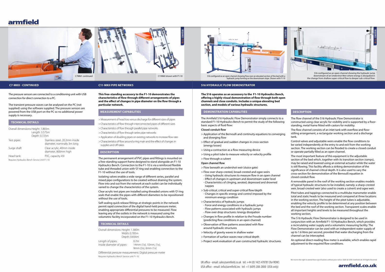
S16 configured as an open channel showing the hydraulic jump downstream of an Undershot Weir where energy is dissipated in
the change from shallow super-critical flow to deeper sub-critical flow.S16 configured as an open channel showing flow over an elevated section of the bed with a
hydraulic jump forming on the downstream slope. Shown with F1-10C11MkII shown with F1-10
REQUIRES F1-10
C7MkII continued
REQUIRES F1-10
REQUIRES F1-10
This free-standing accessory to the F1-10 demonstrates the characteristics of flow through different arrangements of pipes and the effect of changes in pipe diameter on the flow through a particular network.
MEASUREMENT CAPABILITIES
> Measurement of head loss versus discharge for different sizes of pipes
> Characteristics of flow through interconnected pipes of different sizes
> Characteristics of flow through parallel pipe networks
> Characteristics of flow through series pipe networks
> Application of doubling pipes on existing networks to increase flow rate
> Characteristics of flow around a ring main and the effect of changes in supplies and off-takes
DESCRIPTION
The permanent arrangement of PVC pipes and fittings is mounted on a free-standing support frame designed to stand alongside an F1-10 Hydraulics Bench. Connection to the F1-10 is via a reinforced flexible tube and threaded union with ‘O’ ring seal enabling connection to the F1-10 without the use of tools.
Isolating valves enable a wide range of different series, parallel and mixed pipe configurations to be created without draining the system. Flow into and out from the network at each outlet can be individually varied to change the characteristics of the system.
Clear acrylic test pipes are installed using threaded unions with ‘O’ ring seals that enable the pipes with different diameters to be repositioned without the use of tools.
Self-sealing quick release fittings at strategic points in the network permit rapid connection of the digital hand-held pressure meter, enabling appropriate differential pressures to be measured. Flow leaving any of the outlets in the network is measured using the volumetric facility incorporated on the F1-10 Hydraulics Bench.
TECHNICAL DETAILS
Overall dimensions: Height: 1.380m Width: 0.785m Depth: 0.656m
Length of pipes: 0.7m Inside diameter of pipes: 14mm (1x), 10mm, (1x),
9mm (2x), 6mm (1x)
Differential pressure measurement: Digital pressure meterRequires Hydraulics Bench Service unit F1-10
C11-MKII PIPE NETWORKS
UK office - email: [email protected] tel: +44 (0) 1425 478781 (for ROW)USA office - email: [email protected] tel: +1 (609) 208-2800 (USA only) armfield.co.uk
We reserve the right to amend these specif ications without prior notice. E&OE © 2018 Armfield Ltd. All Rights Reserved
The pressure sensors are connected to a conditioning unit with USB connection for direct connection to a PC.
The transient pressure waves can be analysed on the PC (not supplied) using the software supplied. The pressure sensors are powered from the USB port on the PC so no additional power supply is necessary.
TECHNICAL DETAILS
Overall dimensions: Height: 1.865m Length: 3.575m Depth: 0.725m
Test pipes: Stainless steel, 20.2mm inside diameter, nominally 3m long
Surge shaft Clear acrylic, 40mm inside diameter, 800mm high
Head tank: PVC, capacity 45lRequires Hydraulics Bench Service Unit F1-10
The S16 operates as an accessory to the F1-10 Hydraulics Bench, offering a highly visual demonstration of flow through both open channels and close conduits. Includes a unique elevating bed section, and models of various hydraulic structures.
DEMONSTRATION CAPABILITIES
The Armfield S16 Hydraulic Flow Demonstrator simply connects to a standard F1-10 Hydraulics Bench to permit the study of the following basic aspects of fluid flow:
Closed conduit flow > Application of the Bernoulli and continuity equations to converging
and diverging flow
> Effect of gradual and sudden changes in cross-section (energy losses)
> Using a contraction as a flow measuring device
> Using a pitot tube to measure velocity or velocity profile
> Flow through a culvert
Open channel flow> Flow beneath an undershot weir (sluice gate)
> Flow over sharp-crested, broad-crested and ogee weirs - Using hydraulic structures to measure flow in an open channel - Effect of changes in upstream and downstream water level - Characteristics of clinging, aerated, depressed and drowned
nappes
> Sub-critical, critical and super-critical flow/depth - Changes in specific energy and control imposed by the
minimum energy condition
> Characteristics of hydraulic jumps - Force and energy conditions in a hydraulic jump - Flow patterns associated with hydraulic jumps - Flow over drop structures /energy dissipation
> Changes in flow profile in relation to the Froude number (predicting flow conditions in an open channel)
> Observation of flow patterns associated with flow around hydraulic structures
> Velocity of gravity waves in shallow water
> Formation of surface waves near critical depth
> Project work evaluation of user-constructed hydraulic structures
DESCRIPTION
The flow channel of the S16 Hydraulic Flow Demonstrator is constructed using clear acrylic for visibility and is supported by a floor-standing, metal frame fitted with castors for mobility.
The flow channel consists of an inlet tank with overflow and flow-stilling arrangement, a rectangular working section and a discharge tank.
Control valves and adjustable weirs enable the flow conditions to be varied independently at the entry to and exit from the working section. The working section can be flooded to create a closed conduit or operate partially filled as an open channel.
The most important feature of this equipment is the adjustable section of the bed which, together with its transition section (ramps), may be raised and lowered using an external actuator while the water is still flowing. This facility affords a striking demonstration of the significance of channel critical depth. It is also used to vary the cross-section for demonstration of the Bernoulli equation in closed conduit flow.
A removable panel in the roof of the working section enables models of typical hydraulic structures to be installed, namely; a sharp-crested weir, broad-crested weir (also used to create a culvert) and ogee weir.
Pitot tubes and tappings connected to a multitube manometer enable total and static heads to be measured and compared at three locations in the working section. The height of the pitot tubes is adjustable, enabling the velocity profile to be determined at any position between the bed and the roof of the working section. Transparent scales enable all important heights and levels to be measured throughout the working section.
The S16 Hydraulic Flow Demonstrator is designed to be used in conjunction with an Armfield F1-10 Hydraulics Bench, which provides a recirculating water supply and a volumetric measuring facility. The Flow Demonstrator can be used with an independent water supply of up to 1.6 litres per second, provided that water discharging from the channel can be intercepted.
An optional direct-reading flow meter is available, which enables rapid adjustment to the required flow conditions.
S16 HYDRAULIC FLOW DEMONSTRATOR C7-MKII - CONTINUED

UK office - email: [email protected] tel: +44 (0) 1425 478781 (for ROW)USA office - email: [email protected] tel: +1 (609) 208-2800 (USA only) armfield.co.uk
We reserve the right to amend these specif ications without prior notice. E&OE © 2018 Armfield Ltd. All Rights Reserved
Surface oscillations downstream of a Broad Crested Weir when the Weir becomes drowned
ORDERING SPECIFICATION F1-10 AND ACCESSORIES
F1-10 HYDRAULICS BENCH• Mobile, floor-standing service unit for fluid mechanics apparatus• Base constructed from robust, corrosion-
resistant plastic moulding• Top constructed from glass-reinforced plastic• Sump tank capacity 250l• Volumetric flow measurement via remote sight gauge • Stepped tank for low and high flow rates,
with capacities 0-6l and 0-40l• Open channel in benchtop with quick-release outlet fitting• Self-priming centrifugal circulating pump provides water at
21m head at no flow, and a maximum flow of 60 l/min
F1-11 DEAD WEIGHT CALIBRATOR• Precision machined piston and cylinder with levelling screws• Bourdon gauge with inlet and outlet valves• Set of weights• Educational software available as an option
F1-12 HYDROSTATIC PRESSURE• Flotation tank with adjustable feet• Accurately formed plastic quadrant• Lever arm with counterbalance and weight hanger• Educational software available as an option
F1-13 FLOW OVER WEIRS• Two stainless steel weir plates to fit in channel of Hydraulics Bench
• Vernier hook and point gauge with carrier• Stilling baffle• Educational software available as an option
F1-14 METACENTRIC HEIGHT• Rectangular floating pontoon with mast• Variable centre of gravity via moveable weights (transverse and vertical)
• Clinometer indicates angle of heel• Educational software available as an option
F1-15 BERNOULLI’S THEOREM DEMONSTRATION• Venturi section machined from clear acrylic• Seven static pressure tappings plus a total head measurement• Flow control valve• Manometer board with eight tubes• Quick-release fitting for easy connection to Hydraulics Bench• Educational software available as an option
Smooth flow over an ogee weir.Flow over a sharp-crested weir with the nappe ventilated.
F1-16 IMPACT OF A JET• Discharge nozzle inside clear acrylic cylinder• Four different target plates, which fit onto a balance mechanism• Quick-release fitting for easy connection to Hydraulics Bench• Educational software available as an option
F1-17 ORIFICE AND FREE JET FLOW• Constant head tank with two interchangeable orifices• Quick-release fitting for easy connection to Hydraulics Bench• Jet trajectory measured and plotted using adjustable pointers• Educational software available as an option
F1-17A ORIFICE DISCHARGE• Cylindrical clear acrylic tank with orifice fitted in base• Five interchangeable orifices• Pitot tube and wire-on micrometer to
measure jet velocity and diameter• Quick-release fitting for easy connection to Hydraulics Bench• Educational software available as an option
F1-18 ENERGY LOSSES IN PIPES• Vertical test pipe with pressure tappings at entry and exit• Feed either direct from Hydraulics Bench
or from constant head tank• Water and mercury manometers supplied as standard• Quick-release fitting for easy connection to Hydraulics Bench• Educational software available as an option
F1-19 FLOW CHANNEL• Clear acrylic working section fed from stilling tank• Six different models for investigation• Dye injection system• Quick-release fitting for easy connection to Hydraulics Bench• Educational software available as an option
F1-20 OSBORNE REYNOLDS’ DEMONSTRATION• Vertical test section fed from header tank with stilling media• Bellmouth entry to promote smooth flow into the test section• Dye injection system enables flow visualisation• Quick-release fitting for easy connection to Hydraulics Bench• Educational software available as an option
F1-21 FLOW METER DEMONSTRATION• Venturi meter, variable-area meter and orifice plate with flow-control valve
• Pressure tappings to measure head loss across each meter• Supplied with manometer board with eight tubes• Quick-release fitting for easy connection to Hydraulics Bench• Educational software available as an option
F1-22 ENERGY LOSSES IN BENDS AND FITTINGS• Circuit with four bends of different radii• Enlargement, contraction and gate valve, plus flow-control valve• Manometer board with 12 tubes plus differential pressure gauge• Hand pump for pressurisation of manometers• Quick-release fitting for easy connection to Hydraulics Bench• Educational software available as an option
F1-23 FREE AND FORCED VORTICES• Cylindrical vessel with four inlet/outlet ports
to generate free and forced vortices• Three interchangeable orifices and paddle wheel to fit in base of tank
• Measuring bridge with adjustable pointers and internal caliper to measure vortex dimensions
• Pitot tubes for estimation of velocities in vortex• Quick-release fittings for easy connection to hydraulics bench• Educational software available as an option
F1-24 HYDRAULIC RAM PUMP• Pump body manufactured from clear acrylic with
stainless steel pulse and non-return valves• Adjustable acrylic header tank with inlet and outlet hoses• Outlet hose with variable head arrangement• Quick-release fitting for easy connection to Hydraulics Bench• Supplied with weights to load pulse valve• Educational software available as an option
F1-25 PELTON TURBINE• Turbine wheel inside cast housing with acrylic panel to enable viewing
• Mechanical torque measured using dynamometer with spring balances
• Inlet pressure gauge• Quick-release fitting for easy connection to Hydraulics Bench• Educational software available as an option
F1-26 SERIES/PARALLEL PUMPS• Fixed-speed pump with similar performance
characteristics to pump in Hydraulics Bench• Mounted on floor-standing plinth with on/off switch• Discharge manifold with flow control valve and pressure gauges• All hoses and fittings supplied for easy connection to
Hydraulics Bench in either series or parallel configuration• Educational software available as an option
TECHNICAL DETAILS
Width of working section: 77mm Depth of working section: 150mm Length of working section: 1100mm Maximum operating flow rate: 1.6 l/s
ORDERING CODES
S16-10 Hydraulic Flow DemonstratorS16-11 Hydraulic Flow Demonstrator
with direct-reading flow meter
OVERALL DIMENSIONS
Length: 2.20m Width: 0.63m Height: 1.60m Weight (dry): 100kg
SHIPPING SPECIFICATION
Gross weight: 250kg Volume: 3.4m3
S16 - CONTINUED

UK office - email: [email protected] tel: +44 (0) 1425 478781 (for ROW)USA office - email: [email protected] tel: +1 (609) 208-2800 (USA only) armfield.co.uk
We reserve the right to amend these specif ications without prior notice. E&OE © 2018 Armfield Ltd. All Rights Reserved
F1-31 PASCAL’S APPARATUS• Lever arm with sliding weight and spirit level
measures force at the base of the vessel• Three alternative glass vessels supplied: parallel sided, conical and tapering
• Flexible diaphragm retained by ‘O’ ring for ease of replacement
• Height-adjustable pointer enables all vessels to be filled to a common depth
F1-32 FRANCIS TURBINE• Francis runner surrounded by six guide vanes inside PVC
volute with clear acrylic front panel for visualisation• Guide vanes adjustable when turbine is running with scale to
indicate degree of opening and clamp to prevent movement• Francis runner 60mm diameter with 12 blades• Brake force determined using Prony-type brake dynamometer • Inlet pressure gauge with range 0-2 bar• Educational software as an option
F1-33 PITOT TUBE DEMONSTRATOR• Pitot tube with scale to determine the position within the pipe
diameter• Includes pressurised water manometer with scale length
500mm• Approximate dimensions 1.0m x 0.55m x 0.23m• Set of connecting tubes• Instruction manual
C4-MKII MULTIPURPOSE TEACHING FLUME• 76mm wide, 250mm high open channel for use with a
Hydraulics Bench• Available in 2.5m and 5.0m working section lengths• Clear acrylic sides to give visibility of the working section• A jacking system permits the slope of the channel bed to be
adjusted between -1% and +3% • Inlet tank with flow stilling arrangement• Includes a Venturi, sharp and broad-crested weirs, two Vernier
level gauges, adjustable undershot weir and crump weir• Wide range of other models available as accessories• Optional flow meter• Comprehensive instruction manual• Educational software available as an option
C6-MKII-10 FLUID FRICTION APPARATUS• Tubular steel framework supporting a network of pipes and fittings
• Four smooth-bore test pipes of different inside diameters ranging from 4.5mm to 17.2mm, plus roughened pipe
• Large selection of valves, bends and fittings for test: - Artificially roughened pipe - 90° bends (large & small radii) - 90° elbow - 90° mitre - 45° elbow, 45° Y, 90° T - Sudden enlargement - Sudden contraction - Gate valve - Globe valve - Ball valve - Inline strainer - Clear acrylic Venturi - Clear acrylic orifice meter - Clear acrylic pipe section with a pitot tube & static tapping
• Acrylic pipe section with Venturi, orifice plate and pitot tube• 38 tapping points for head loss measurement• Supplied with fittings for easy connection to
Hydraulics Bench (no tools required)• Various instrumentation options available including
water, mercury or digital manometers• Educational software available as an option• Optional data logging accessory, comprises two
electronic pressure sensors, electronic flow sensor, signal conditioning USB interface and software enabling logging of measured variables using a PC.
C7-MKII PIPE SURGE AND WATER HAMMER APPARATUS• A free-standing unit designed to demonstrate the
phenomena of pipe surge and water hammer when connected to a Hydraulics Bench
• Includes two separate stainless steel test pipes, both 3m long, constant head tank, with slow- and fast-acting valve
• A transparent surge shaft (40mm diameter and 800mm high) with scale enables transient water levels to be observed and timed
• Electronic sensors used to measure pressure transients at two locations in the water hammer test pipe, one adjacent to fast-acting valve and one halfway along the test pipe
• Pressure transients monitored using a PC (not supplied) using a USB connection from the pressure transducers (requires no external electrical supply)
• Straight metal pipes used, rather than a coiled arrangement, to minimise distortion to the pressure profile
C11-MKII PIPE NETWORKS• Specifically designed to enable the setting up of a
wide range of different pipe arrays (networks)• Pipe network mounted on free-standing support
frame for use alongside a Hydraulics Bench• Clear acrylic test pipes are all 0.7m long with inside
diameters of 1x 6mm, 2x 9mm, 1x 10mm, 1x 14mm• Differential pressure measurements obtained using a
hand-held electronic pressure meter with self-sealing quick-release connections to the pipe network
• Flows into and out from the appropriate network can be varied individually
S16 HYDRAULIC FLOW DEMONSTRATOR• A floor-standing flow channel for use with a Hydraulics Bench• Working section 77mm wide, 150mm high and 1100mm long• Can be configured to demonstrate flow in
open channels and closed conduits• Clear acrylic sides for good visibility of flow patterns created• Stilling arrangement at inlet to promote
smooth flow into the working section• Section of bed can be elevated continuously
and locked at the required height• Discharge tank incorporates flow control
valve for convenience in setting up• Total and static heads indicated on multitube manometer connected to Pitot tubes and static tappings at three locations in working section
• Pitot tubes mounted through bed of channel for ease of priming and height adjustment (can be traversed from floor to roof to measure velocity profile)
• Transparent scales enable measurement of all important heights and levels
• Models of hydraulic structures supplied include undershot weir (sluice gate) at the inlet, overshot weir at the outlet, sharp-crested weir, broad-crested weir (also used to create a culvert) and ogee weir
• Suitable for project work with user-created hydraulic structures• Optional direct-reading flow meter to aid
setting up of demonstrations• Comprehensive instruction manual supplied
F1-27 CENTRIFUGAL PUMPS CHARACTERISTICS• Variable-speed pump with similar performance characteristics to pump in Hydraulics Bench
• Mounted on floor-standing plinth with variable speed inverter drive
• Discharge manifold with flow control valve and pressure gauges• All hoses and fittings supplied for easy connection to
Hydraulics Bench in either series or parallel configuration• Educational software available as an option
F1-28 CAVITATION DEMONSTRATION• Circular Venturi-shaped test section manufactured
from clear acrylic for full visualisation of cavitation• Three Bourdon gauges indicate the static pressure upstream of the contraction, inside the throat and downstream of the expansion in the test section
• Flow-control valves upstream and downstream of the test section enable flow conditions to be optimised for the demonstration of cavitation
• Quick-release fitting for easy connection to Hydraulics Bench• Educational software available as an option
F1-29 FLUID STATICS AND MANOMETRY• Demonstrates the basic principles of
hydrostatics and manometry• Includes vertical tube with variable cross
section, scale length 460 mm• Includes demonstrations of the following types of manometer:
- Single piezometer manometer tube, scale length 460mm - Inclined manometer with inclinations of 5°, 30°, 60° and 90° (vertical)
- Enlarged limb-manometer - ‘U’ tube manometer (air over liquid), scale length 460mm - ‘U’ tube manometer (liquid over liquid), scale length 460mm - Inverted pressurised ‘U’ tube manometer, scale length 460mm• Level measurement using Vernier hook and point
gauge, range 0-150mm with 0.1mm resolution• Enables the effect of friction to be
demonstrated when fluid is in motion
F1-30 FLUID PROPERTIES• Components stored on support frame made from PVC• Two hydrometer jars 50mm diameter and 450mm high• Universal hydrometer with varying resolution
of 0.01 at 0.70 SG to 0.5 at 2.00 SG• Two falling-sphere viscometer tubes 40mm diameter with calibration marks at 0, 25, 100, 175, 200 and 220mm
• Steel spheres 1.588, 2.381 and 3.175mm diameter• Spirit-filled thermometer glass, range -10° to 50°C • Aneroid barometer, range 910-1060 mbar• Six capillary tubes 150mm long with
0.4, 0.6, 0.8, 1.2, 1.7 and 2.2mm bore• Density bottle (pycnometer), capacity 50ml • Dual-scale lever balance, ranges 0-250g x 1g and 0-1kg x 10g

Data input screen
Educational software, specifically developed for the Armfield Hydraulics Bench and associated accessories, offering a complete teaching package of coursework and laboratory investigation. The familiar Windows environment enables the student to explore the principles of each accessory quickly and easily, enabling comparison of theory and practical measurements, thus providing a good understanding of the principles involved.The software has been designed for maximum flexibility and ease of use. Comprehensive Help screens guide the student through both the theoretical background and the practical investigation of the equipment in question. All the information required to set up and run the experiment is included in the software, together with suggested laboratory investigations and further questions for the student to answer.
ADVANTAGES
> Reduces lecturer and technician support time in the laboratory by leading the student logically through the use of the equipment and the experimental procedures
> Can be used outside the laboratory to familiarise the student with the equipment and procedures, prior to performing the practical training exercise
> Reinforces understanding of the theoretical concepts involved
> Reinforces understanding of practical concepts such as taking readings, experimental errors, units of measurement etc
> Eliminates the need for repetitive calculations but still requires the student to demonstrate understanding of the mathematical processes used
> Enables the student to process all results during the laboratory session, thus giving immediate feedback on the success or otherwise of the investigation while still having access to the equipment
FEATURES
This advanced educational software contains a number of unique features aimed at enhancing the student’s understanding of the subjects being studied.
These features include: > Presentation screens provide details on how to use the software, the
theory behind the investigations, how to set up the equipment, etc
> Presentations are backed up by comprehensive Help screens providing more detail and additional background material
> A mimic diagram of the equipment is provided
> The user enters the measured values into the relevant positions on the diagram
> The user can add written notes, which are recorded with the logged data in the appropriate time slot
> Results can be displayed graphically, or in tabular format
> Full control is provided over the displayed graphs, including scaling, axes and which variables are displayed
> The data is exportable to general purpose spreadsheets or word processors as applicable
ORDERING INFORMATION
Software covering the full range of accessories is available on a USB stick, order code F1-aBASIC.
COMPUTER REQUIREMENTS
PC running Windows 98, or later. Computer is not supplied by Armfield.
F1-aBASIC - 308 Armsoft Fluid Mechanics Software
FOR FURTHER INFORMATION ON THE ADVANCED FEATURES OF THE SOPHISTICATED ARMFIELD SOFTWARE VISIT: www.discoverarmfield.co.uk/data/armsoft
301
SOFTWAREArmSoft™
Knowledge base> 26 years’ expertise in industrial R&D technology > 50 years’ providing engaging engineering teaching equipment
Benefit from our experience, just call or email to discuss your laboratory needs, latest project or application.
AftercareInstallation Commissioning TrainingService and maintenance Support: armfieldassist.com
Products certified
An ISO 9001 Company
armfield.co.uk