MECHANICAL FLUID MECHANICS - · PDF filemechanical fluid mechanics
22
MECHANICAL FLUID MECHANICS 1 | Page THE GATE COACH All Rights Reserved 28, Jia Sarai N.Delhi-16, 26528213,-9998
-
Upload
trinhthien -
Category
Documents
-
view
1.000 -
download
47
Transcript of MECHANICAL FLUID MECHANICS - · PDF filemechanical fluid mechanics
MECHANICAL FLUID MECHANICS
1 | P a g e THE GATE COACH All Rights Reserved 28, Jia Sarai N.Delhi-16, 26528213,-9998
MECHANICAL FLUID MECHANICS
2 | P a g e THE GATE COACH All Rights Reserved 28, Jia Sarai N.Delhi-16, 26528213,-9998
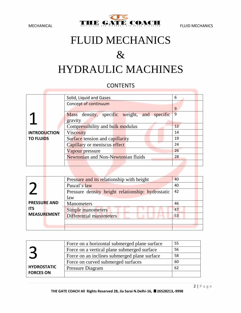
FLUID MECHANICS
&
HYDRAULIC MACHINES
CONTENTS
1 INTRODUCTION TO FLUIDS
Solid, Liquid and Gases 6
Concept of continuum 9
Mass density, specific weight, and specific
gravity
9
Compressibility and bulk modulus 12
Viscosity 14
Surface tension and capillarity 19
Capillary or meniscus effect 24
Vapour pressure 26
Newtonian and Non-Newtonian fluids 28
2 PRESSURE AND ITS MEASUREMENT
Pressure and its relationship with height 40
Pascal’s law 40
Pressure density height relationship: hydrostatic
law
42
Manometers 46
Simple manometers 47
Differential manometers 53
3 HYDROSTATIC FORCES ON
Force on a horizontal submerged plane surface 55
Force on a vertical plane submerged surface 56
Force on an inclines submerged plane surface 58
Force on curved submerged surfaces 60
Pressure Diagram 62
MECHANICAL FLUID MECHANICS
3 | P a g e THE GATE COACH All Rights Reserved 28, Jia Sarai N.Delhi-16, 26528213,-9998
SUBMERGED BODIES
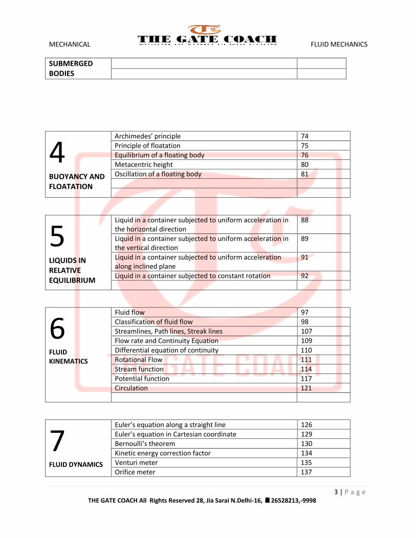
4 BUOYANCY AND FLOATATION
Archimedes’ principle 74
Principle of floatation 75
Equilibrium of a floating body 76
Metacentric height 80
Oscillation of a floating body 81
5 LIQUIDS IN RELATIVE EQUILIBRIUM
Liquid in a container subjected to uniform acceleration in the horizontal direction
88
Liquid in a container subjected to uniform acceleration in the vertical direction
89
Liquid in a container subjected to uniform acceleration along inclined plane
91
Liquid in a container subjected to constant rotation 92
6 FLUID KINEMATICS
Fluid flow 97
Classification of fluid flow 98
Streamlines, Path lines, Streak lines 107
Flow rate and Continuity Equation 109
Differential equation of continuity 110
Rotational Flow 111
Stream function 114
Potential function 117
Circulation 121
7 FLUID DYNAMICS
Euler’s equation along a straight line 126
Euler’s equation in Cartesian coordinate 129
Bernoulli’s theorem 130
Kinetic energy correction factor 134
Venturi meter 135
Orifice meter 137
MECHANICAL FLUID MECHANICS
4 | P a g e THE GATE COACH All Rights Reserved 28, Jia Sarai N.Delhi-16, 26528213,-9998
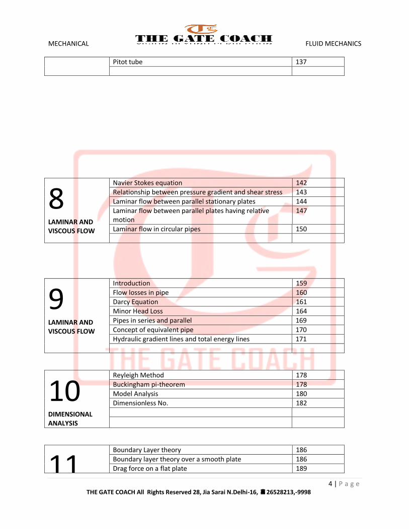
Pitot tube 137
8 LAMINAR AND VISCOUS FLOW
Navier Stokes equation 142
Relationship between pressure gradient and shear stress 143
Laminar flow between parallel stationary plates 144
Laminar flow between parallel plates having relative motion
147
Laminar flow in circular pipes 150
9 LAMINAR AND VISCOUS FLOW
Introduction 159
Flow losses in pipe 160
Darcy Equation 161
Minor Head Loss 164
Pipes in series and parallel 169
Concept of equivalent pipe 170
Hydraulic gradient lines and total energy lines 171
10 DIMENSIONAL ANALYSIS
Reyleigh Method 178
Buckingham pi-theorem 178
Model Analysis 180
Dimensionless No. 182
11 Boundary Layer theory 186
Boundary layer theory over a smooth plate 186
Drag force on a flat plate 189
MECHANICAL FLUID MECHANICS
5 | P a g e THE GATE COACH All Rights Reserved 28, Jia Sarai N.Delhi-16, 26528213,-9998
BOUNDARY LAYER FLOW
Thermal boundary layer 191
Separation Boundary layer 192
12 NOTCHES AND WEIRS
Introduction 193
Geometry of flow motion 194
Discharge over a rectangular weir 197
Discharge over a submerged rectangular weir 199
Discharge over a broad weir 200
Discharge over a triangular weir or V-notch 201
Discharge over a trapezoidal weir 202
13 FLOW THROUGH ORIFICE AND MOUTHPIECES
Introduction 204
Hydraulic coefficient 205
Discharge through a sharp edged large orifice 207
Discharge through a submerged orifice 208
Discharge through a partially submerged orifice 209
Flow through external cylindrical mouthpiece 210
Flow through re-entrant 211
14 OPEN CHANNEL FLOW
Related terms 216
Classification 218
The Chezy Equation 218
Economic section for maximum discharge 220
Most economical rectangular section 220
Most economical trapezoidal section 221
Most economical circular section 224
15 IMPACT OF FREE JETS
Impulse momentum theorem 229
Jet striking a stationary flat plate 230
Jet striking a stationary flat plate inclined at an angle 231
Jet striking a moving straight plate 232
Jet striking a moving straight plate inclined at an angle 234
Jet striking at centre of stationary vane 235
Jet striking at centre of moving vane 236
Jet striking stationary vane tangentially at one tip 238
Jet striking moving vane tangentially at one tip 239
MECHANICAL FLUID MECHANICS
6 | P a g e THE GATE COACH All Rights Reserved 28, Jia Sarai N.Delhi-16, 26528213,-9998
16 HYDRAULIC TURBINE
Impulse and reaction turbine 243
Pelton turbine 244
Head , power and efficiency 248
Design aspects of Pelton Wheel 250
Radial flow impulse turbine 252
Francis turbine 255
Propeller and Kaplan turbine 259
Model Relationships 265
17 HYDRAULIC PUMP
Classification 273
Centrifugal pump 273
Velocity diagram 276
Pump losses and efficiency 280
Pressure rise in impeller 282
Priming 285
Axial flow pump 286
Reciprocating pumps 287
18 HYDRAULIC SYSTEMS
Hydraulic accumulator 296
Torque convertor 297
Hydraulic Ram 297
MECHANICAL FLUID MECHANICS
7 | P a g e THE GATE COACH All Rights Reserved 28, Jia Sarai N.Delhi-16, 26528213,-9998
1. BUOYANCY AND FLOATATION
ARCHIMEDE’S PRINCIPLE
Fluid exerts pressure on the surfaces of a body which is either partially or completely
submerged into it.
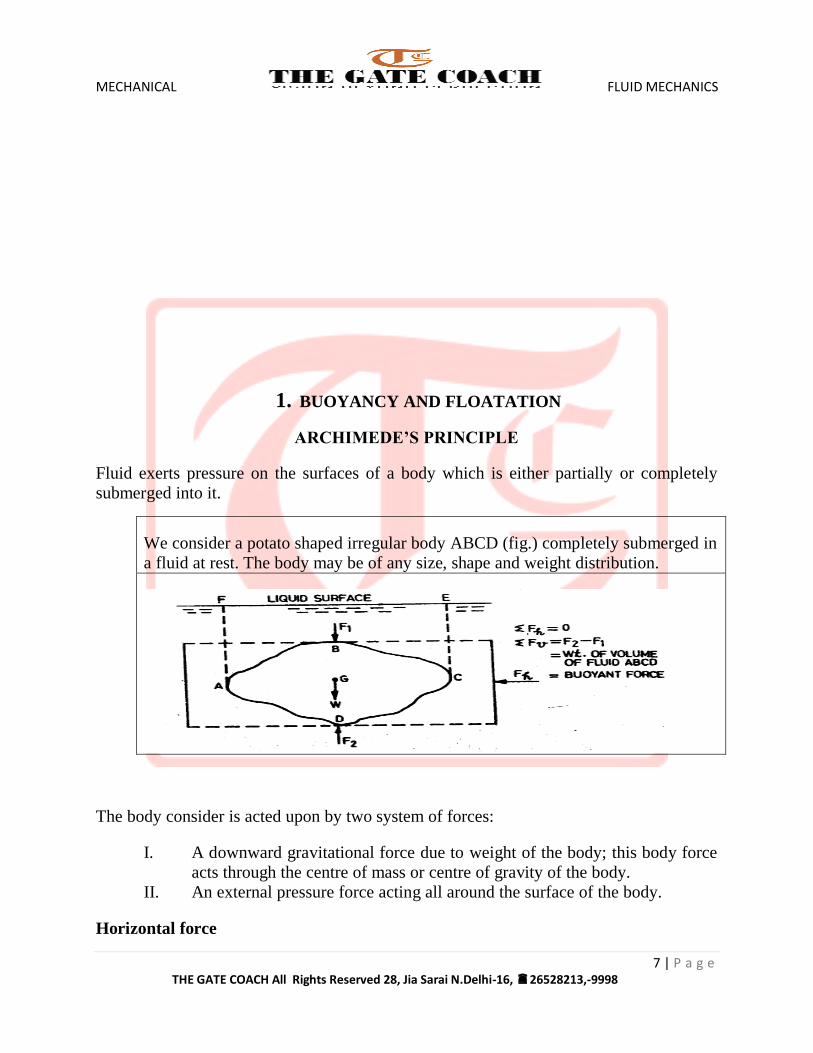
We consider a potato shaped irregular body ABCD (fig.) completely submerged in
a fluid at rest. The body may be of any size, shape and weight distribution.
The body consider is acted upon by two system of forces:
I. A downward gravitational force due to weight of the body; this body force
acts through the centre of mass or centre of gravity of the body.
II. An external pressure force acting all around the surface of the body.
Horizontal force
MECHANICAL FLUID MECHANICS
8 | P a g e THE GATE COACH All Rights Reserved 28, Jia Sarai N.Delhi-16, 26528213,-9998
A horizontal component of force equal to the force on a horizontal projection into a
vertical plane. We consider any vertical plane drawn through the body.
The projected areas of the two sections ABD and BCD of the body onto a vertical plane
are equal.
Consequently the horizontal forces on these two surfaces are equal and opposite, and so the net horizontal force is zero.
Vertical force
A vertical component of force equal to the weight of the fluid vertically above the curved
surface.
For the submerged body under consideration, a vertically downward force F1 acting on
the upper surface equals the weight of volume of fluid ABCEF.
Likewise, a vertically upward force F2 acting on the lower surface equals the weight of volume of fluid ADCEF.
Buoyant force
A body submerged in a fluid experience an upward thrust due to fluid pressure. This force is called buoyant force;
Buoyancy
The tendency of the body to be lifted upward in a fluid due to buoyant force is called buoyancy.
Centre of Buoyancy
The line of action of the buoyant force is vertical and passes through the centre of gravity
of the displaced fluid, i.e. the centroid of the displaced volume. This centroid of the displaced fluid volume is called the centre of buoyancy.
MECHANICAL FLUID MECHANICS
9 | P a g e THE GATE COACH All Rights Reserved 28, Jia Sarai N.Delhi-16, 26528213,-9998
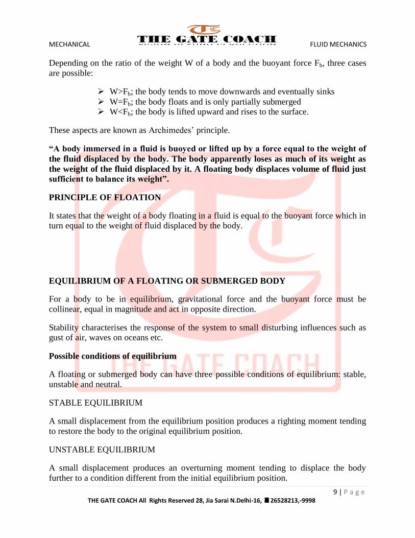
Depending on the ratio of the weight W of a body and the buoyant force Fb, three cases
are possible:
W>Fb; the body tends to move downwards and eventually sinks
W=Fb; the body floats and is only partially submerged W<Fb; the body is lifted upward and rises to the surface.
These aspects are known as Archimedes’ principle.
“A body immersed in a fluid is buoyed or lifted up by a force equal to the weight of
the fluid displaced by the body. The body apparently loses as much of its weight as
the weight of the fluid displaced by it. A floating body displaces volume of fluid just
sufficient to balance its weight”.
PRINCIPLE OF FLOATION
It states that the weight of a body floating in a fluid is equal to the buoyant force which in turn equal to the weight of fluid displaced by the body.
EQUILIBRIUM OF A FLOATING OR SUBMERGED BODY
For a body to be in equilibrium, gravitational force and the buoyant force must be
collinear, equal in magnitude and act in opposite direction.
Stability characterises the response of the system to small disturbing influences such as gust of air, waves on oceans etc.
Possible conditions of equilibrium
A floating or submerged body can have three possible conditions of equilibrium: stable,
unstable and neutral.
STABLE EQUILIBRIUM
A small displacement from the equilibrium position produces a righting moment tending
to restore the body to the original equilibrium position.
UNSTABLE EQUILIBRIUM
A small displacement produces an overturning moment tending to displace the body
further to a condition different from the initial equilibrium position.
MECHANICAL FLUID MECHANICS
10 | P a g e THE GATE COACH All Rights Reserved 28, Jia Sarai N.Delhi-16, 26528213,-9998
NEUTRAL EQUILIBRIUM
The body remains at rest in any position to which it may be displaced. No net force tends
to return the body to its original state or to drive it further away from the original
condition.
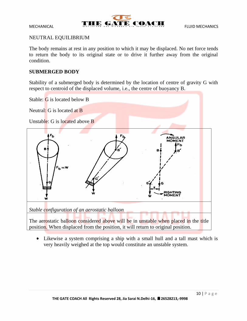
SUBMERGED BODY
Stability of a submerged body is determined by the location of centre of gravity G with respect to centroid of the displaced volume, i.e., the centre of buoyancy B.
Stable: G is located below B
Neutral: G is located at B
Unstable: G is located above B
Stable configuration of an aerostatic balloon
The aerostatic balloon considered above will be in unstable when placed in the title
position. When displaced from the position, it will return to original position.
Likewise a system comprising a ship with a small hull and a tall mast which is
very heavily weighed at the top would constitute an unstable system.
MECHANICAL FLUID MECHANICS
11 | P a g e THE GATE COACH All Rights Reserved 28, Jia Sarai N.Delhi-16, 26528213,-9998
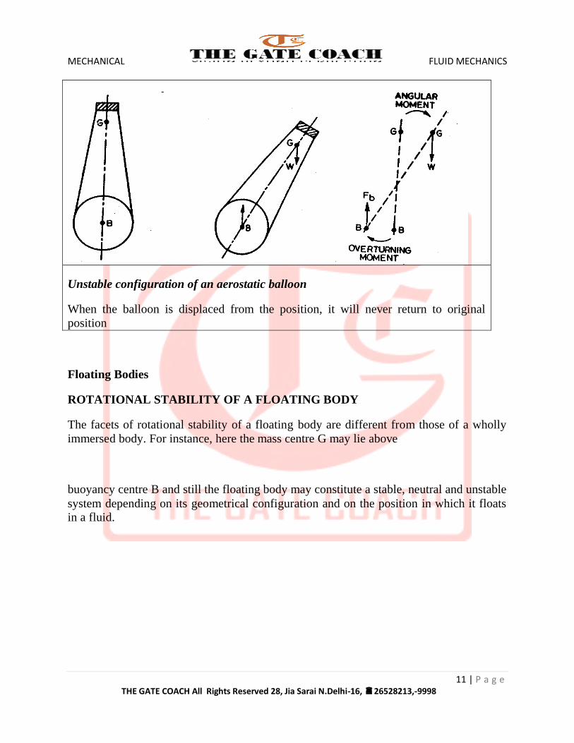
Unstable configuration of an aerostatic balloon
When the balloon is displaced from the position, it will never return to original
position
Floating Bodies
ROTATIONAL STABILITY OF A FLOATING BODY
The facets of rotational stability of a floating body are different from those of a wholly
immersed body. For instance, here the mass centre G may lie above
buoyancy centre B and still the floating body may constitute a stable, neutral and unstable
system depending on its geometrical configuration and on the position in which it floats in a fluid.
MECHANICAL FLUID MECHANICS
12 | P a g e THE GATE COACH All Rights Reserved 28, Jia Sarai N.Delhi-16, 26528213,-9998
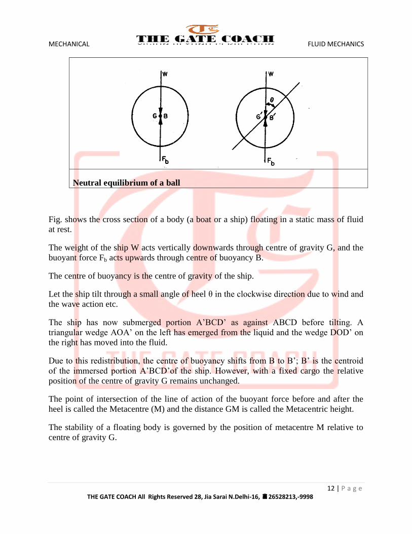
Neutral equilibrium of a ball
Fig. shows the cross section of a body (a boat or a ship) floating in a static mass of fluid at rest.
The weight of the ship W acts vertically downwards through centre of gravity G, and the
buoyant force Fb acts upwards through centre of buoyancy B.
The centre of buoyancy is the centre of gravity of the ship.
Let the ship tilt through a small angle of heel θ in the clockwise direction due to wind and
the wave action etc.
The ship has now submerged portion A’BCD’ as against ABCD before tilting. A
triangular wedge AOA’ on the left has emerged from the liquid and the wedge DOD’ on
the right has moved into the fluid.
Due to this redistribution, the centre of buoyancy shifts from B to B’; B’ is the centroid
of the immersed portion A’BCD’of the ship. However, with a fixed cargo the relative
position of the centre of gravity G remains unchanged.
The point of intersection of the line of action of the buoyant force before and after the
heel is called the Metacentre (M) and the distance GM is called the Metacentric height.
The stability of a floating body is governed by the position of metacentre M relative to
centre of gravity G.
MECHANICAL FLUID MECHANICS
13 | P a g e THE GATE COACH All Rights Reserved 28, Jia Sarai N.Delhi-16, 26528213,-9998
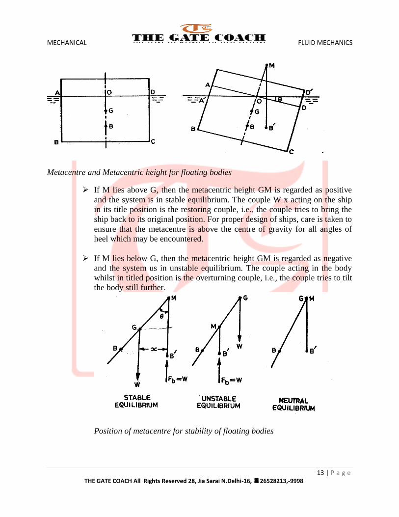
Metacentre and Metacentric height for floating bodies
If M lies above G, then the metacentric height GM is regarded as positive
and the system is in stable equilibrium. The couple W x acting on the ship
in its title position is the restoring couple, i.e., the couple tries to bring the
ship back to its original position. For proper design of ships, care is taken to
ensure that the metacentre is above the centre of gravity for all angles of
heel which may be encountered.
If M lies below G, then the metacentric height GM is regarded as negative
and the system us in unstable equilibrium. The couple acting in the body
whilst in titled position is the overturning couple, i.e., the couple tries to tilt
the body still further.
Position of metacentre for stability of floating bodies
MECHANICAL FLUID MECHANICS
14 | P a g e THE GATE COACH All Rights Reserved 28, Jia Sarai N.Delhi-16, 26528213,-9998
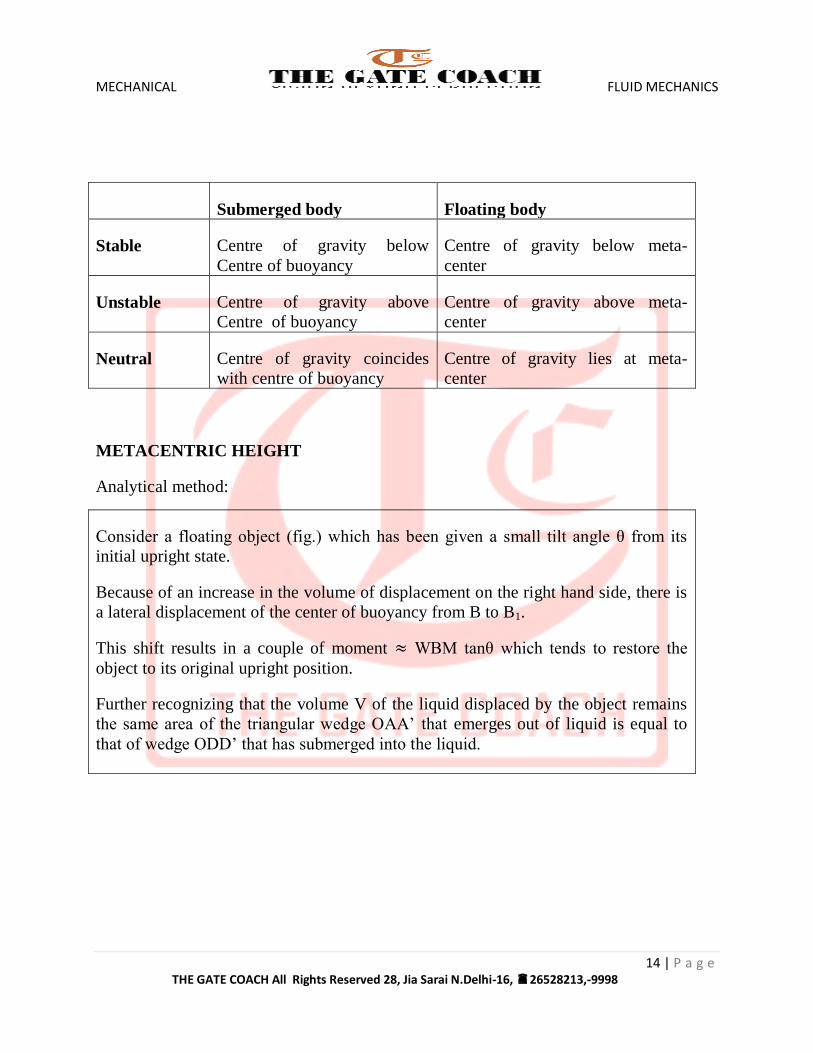
Submerged body Floating body
Stable Centre of gravity below
Centre of buoyancy
Centre of gravity below meta-
center
Unstable Centre of gravity above
Centre of buoyancy
Centre of gravity above meta-
center
Neutral Centre of gravity coincides
with centre of buoyancy
Centre of gravity lies at meta-
center
METACENTRIC HEIGHT
Analytical method:
Consider a floating object (fig.) which has been given a small tilt angle θ from its
initial upright state.
Because of an increase in the volume of displacement on the right hand side, there is
a lateral displacement of the center of buoyancy from B to B1.
This shift results in a couple of moment WBM tanθ which tends to restore the
object to its original upright position.
Further recognizing that the volume V of the liquid displaced by the object remains
the same area of the triangular wedge OAA’ that emerges out of liquid is equal to
that of wedge ODD’ that has submerged into the liquid.
MECHANICAL FLUID MECHANICS
15 | P a g e THE GATE COACH All Rights Reserved 28, Jia Sarai N.Delhi-16, 26528213,-9998
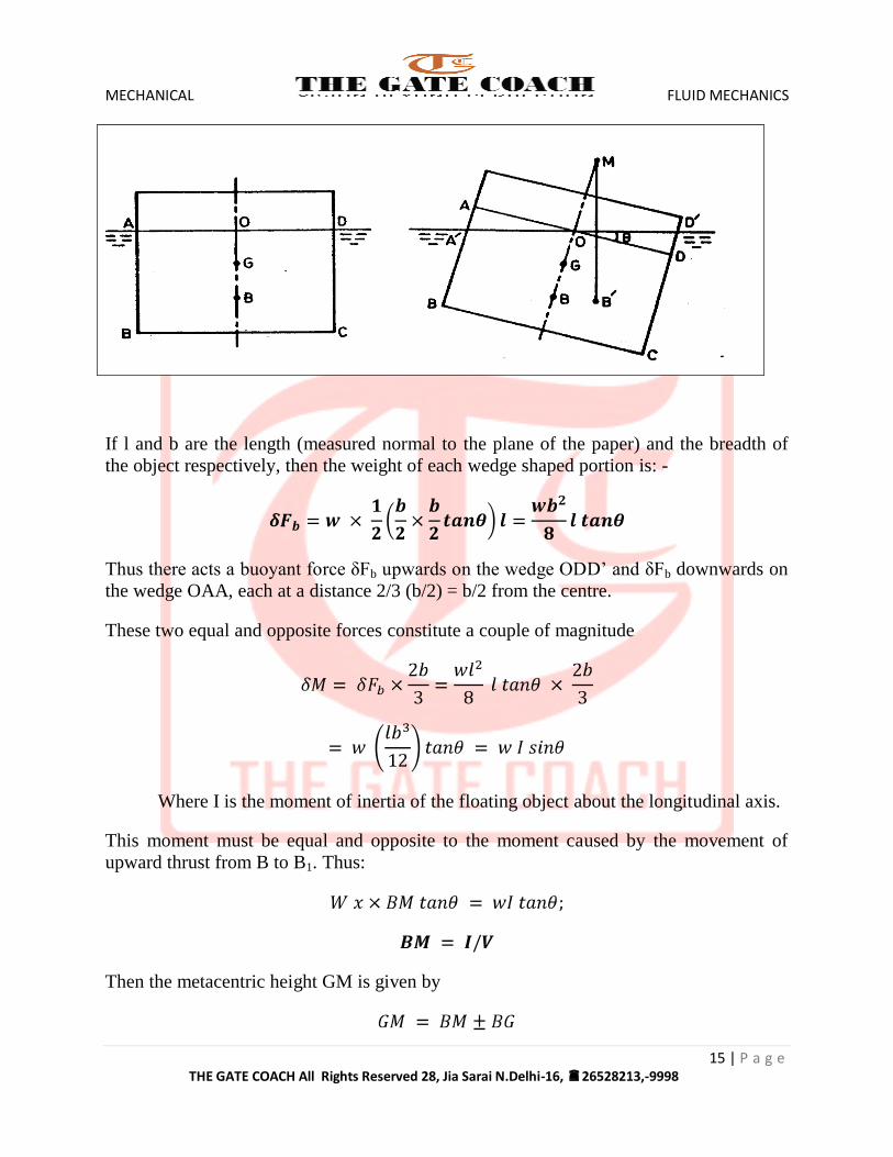
If l and b are the length (measured normal to the plane of the paper) and the breadth of
the object respectively, then the weight of each wedge shaped portion is: -
Thus there acts a buoyant force δFb upwards on the wedge ODD’ and δFb downwards on
the wedge OAA, each at a distance 2/3 (b/2) = b/2 from the centre.
These two equal and opposite forces constitute a couple of magnitude
Where I is the moment of inertia of the floating object about the longitudinal axis.
This moment must be equal and opposite to the moment caused by the movement of
upward thrust from B to B1. Thus:
Then the metacentric height GM is given by
MECHANICAL FLUID MECHANICS
16 | P a g e THE GATE COACH All Rights Reserved 28, Jia Sarai N.Delhi-16, 26528213,-9998
The –ve sign is used when G lies above B and + ve sign when G lies below B.
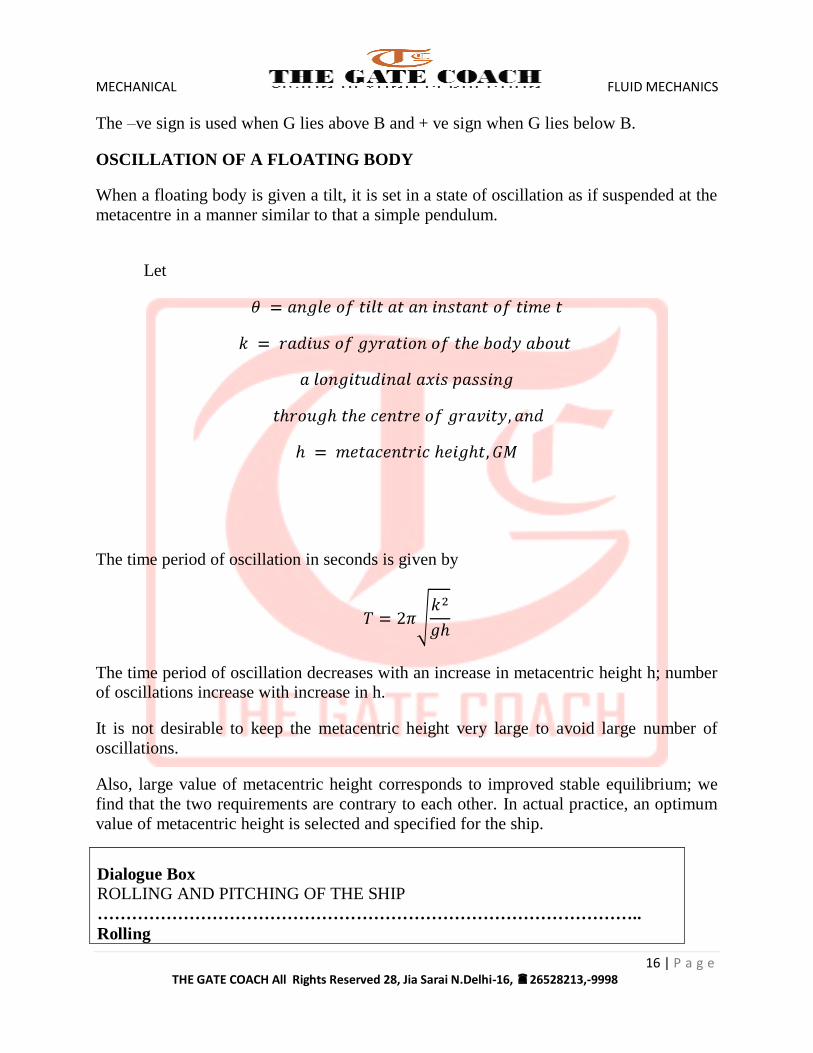
OSCILLATION OF A FLOATING BODY
When a floating body is given a tilt, it is set in a state of oscillation as if suspended at the
metacentre in a manner similar to that a simple pendulum.
Let
The time period of oscillation in seconds is given by
The time period of oscillation decreases with an increase in metacentric height h; number of oscillations increase with increase in h.
It is not desirable to keep the metacentric height very large to avoid large number of
oscillations.
Also, large value of metacentric height corresponds to improved stable equilibrium; we
find that the two requirements are contrary to each other. In actual practice, an optimum
value of metacentric height is selected and specified for the ship.
Dialogue Box
ROLLING AND PITCHING OF THE SHIP
…………………………………………………………………………………..
Rolling
MECHANICAL FLUID MECHANICS
17 | P a g e THE GATE COACH All Rights Reserved 28, Jia Sarai N.Delhi-16, 26528213,-9998
The oscillatory motion of a ship or boat about its longitudinalaxis is known as
rolling.
Pitching
The oscillatory motion of a ship or boat about its transverse axis is known as
pitching.
Dialogue Box
DESIGN CRITERIA OF THE SHIP
………………………………………………………………………………….
Expressions for meta-centric height and the time period of oscillation has
been derived for rolling motion, same may be adopted for pitching motion
also.
Since the moment of inertia of the cross-sectional area of ship or boat at
liquid surface about its transverse axis is much more than the same about
longitudinal axis, hence metacentric height is invariably larger than that for
rolling motion.Hence a ship has a safe metacentric height for rolling motion
then it will be safe in pitching motion also.
Practical Applications
Increase of metacentric height gives
- Greater stability to floating body
- Reduces the time period of rolling of the body.
A smaller value of time period of rolling of a passenger ship is quite
uncomfortable for the passengers and may damage the structure of ship.
In case of warships and racing yachts, the stability is more important than the
comfort, hence have larger metacentric height.
In case of cargo ships, metacentric height varies with loading and hence some
control on the value of metacentric height as well as the time period of rolling
is possible by adjusting the position of cargo.
MECHANICAL FLUID MECHANICS
18 | P a g e THE GATE COACH All Rights Reserved 28, Jia Sarai N.Delhi-16, 26528213,-9998
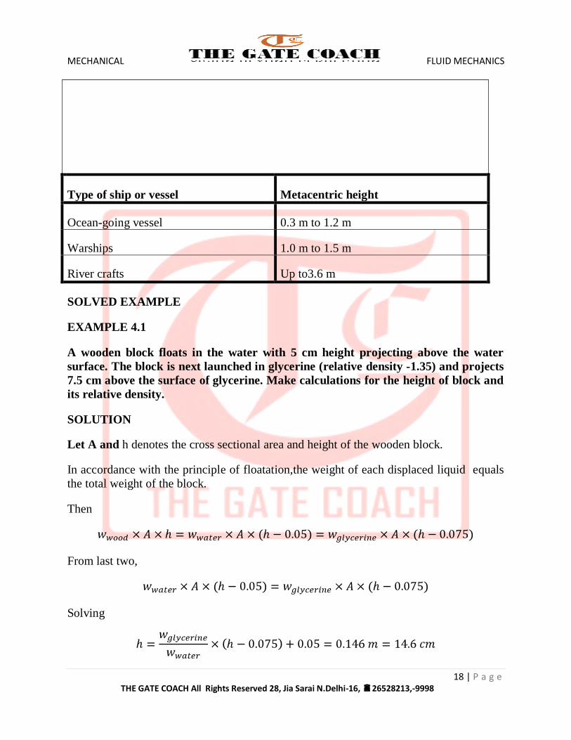
Type of ship or vessel Metacentric height
Ocean-going vessel 0.3 m to 1.2 m
Warships 1.0 m to 1.5 m
River crafts Up to3.6 m
SOLVED EXAMPLE
EXAMPLE 4.1
A wooden block floats in the water with 5 cm height projecting above the water
surface. The block is next launched in glycerine (relative density -1.35) and projects
7.5 cm above the surface of glycerine. Make calculations for the height of block and
its relative density.
SOLUTION
Let A and h denotes the cross sectional area and height of the wooden block.
In accordance with the principle of floatation,the weight of each displaced liquid equals
the total weight of the block.
Then
From last two,
Solving
MECHANICAL FLUID MECHANICS
19 | P a g e THE GATE COACH All Rights Reserved 28, Jia Sarai N.Delhi-16, 26528213,-9998
From first two
Relative density of wood is 0.657
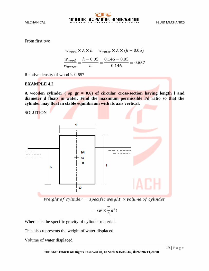
EXAMPLE 4.2
A wooden cylinder ( sp gr = 0.6) of circular cross-section having length l and
diameter d floats in water. Find the maximum permissible l/d ratio so that the
cylinder may float in stable equilibrium with its axis vertical.
SOLUTION
Where s is the specific gravity of cylinder material.
This also represents the weight of water displaced.
Volume of water displaced
MECHANICAL FLUID MECHANICS
20 | P a g e THE GATE COACH All Rights Reserved 28, Jia Sarai N.Delhi-16, 26528213,-9998
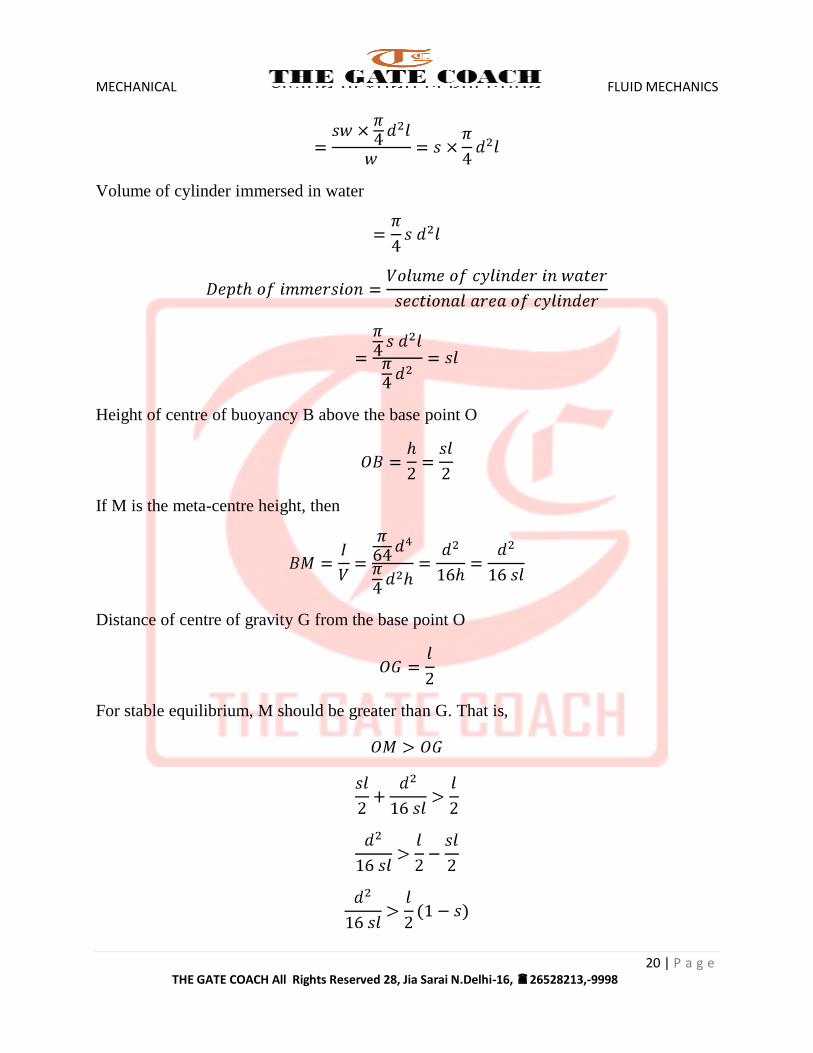
Volume of cylinder immersed in water
Height of centre of buoyancy B above the base point O
If M is the meta-centre height, then
Distance of centre of gravity G from the base point O
For stable equilibrium, M should be greater than G. That is,
MECHANICAL FLUID MECHANICS
21 | P a g e THE GATE COACH All Rights Reserved 28, Jia Sarai N.Delhi-16, 26528213,-9998
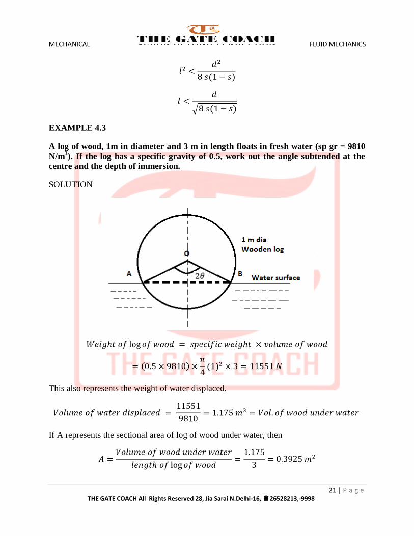
EXAMPLE 4.3
A log of wood, 1m in diameter and 3 m in length floats in fresh water (sp gr = 9810
N/m3). If the log has a specific gravity of 0.5, work out the angle subtended at the
centre and the depth of immersion.
SOLUTION
This also represents the weight of water displaced.
If A represents the sectional area of log of wood under water, then
MECHANICAL FLUID MECHANICS
22 | P a g e THE GATE COACH All Rights Reserved 28, Jia Sarai N.Delhi-16, 26528213,-9998
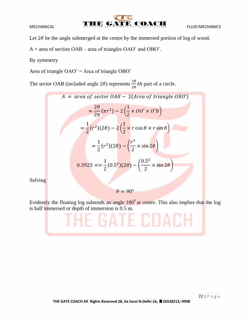
Let 2 be the angle submerged at the centre by the immersed portion of log of wood.
A = area of section OAB – area of triangles OAO’ and OBO’.
By symmetry
Area of triangle OAO’ = Area of triangle OBO’
The sector OAB (included angle 2 ) represents part of a circle.
Solving
Evidently the floating log subtends an angle 1800
at centre. This also implies that the log is half immersed or depth of immersion is 0.5 m.