Fluid Flow Conditioning - VSL · Fluid Flow Conditioning March 2014 ... • Swirl is the rotation...
52
3/29/2014 1 Fluid Flow Conditioning March 2014 CPA Flow Conditioning 2014 March‐29‐14 Flow Conditioning • There is no flow meter on the market that needs flow conditioning. • All flow meters are effective without any type of flow conditioning.
-
Upload
vuongtuyen -
Category
Documents
-
view
214 -
download
0
Transcript of Fluid Flow Conditioning - VSL · Fluid Flow Conditioning March 2014 ... • Swirl is the rotation...

3/29/2014
1
Fluid Flow Conditioning
March 2014
CPA Flow Conditioning 2014March‐29‐14
Flow Conditioning
• There is no flow meter on the market that needs flow conditioning.
• All flow meters are effective without any type of flow conditioning.

3/29/2014
2
CPA Flow Conditioning 2014March‐29‐14
Flow Conditioning
Why do we want to use flow conditioners then?
• Can eliminate up to 80 – 90% of pipeline swirl.
• Restore flow profile symmetry and eliminate distortions.
• Isolates the flow meter from upstream disturbances.
• Allows much shorter meter runs to be used with much higher repeatability.
• Improves the benefits of many USM diagnostics by providing flow stabilty.
• Helps with noise or pulsation problems.
• Helps balance the pressure, velocity and flow rate of meter tubes running in parallel.
• They UNLOAD the flow meter, helping it become even more accurate.
CPA Flow Conditioning 2014March‐29‐14
Flow Conditioning
What if we have debris in our pipe?
• The debris has to go somewhere, ignoring the flow conditioner won’t make it disappear.
• Install a filter (or another flow conditioner UPSTREAM of the meter run to catch the debris).
• Without something to catch debris, we risk damaging or destroying any sample probes, thermo wells or any other equipment in the pipe.
• Better hope there isn’t a compressor or turbine downstream somewhere.
• If the gaskets are unraveling, recommend switching to Flexitallic CGI gaskets with an inner ring to keep the windings intact.
3/29/2014
3
CPA Flow Conditioning 2014March‐29‐14
What is a Flow Conditioner?
CPA Flow Conditioning 2014March‐29‐14
What is a Flow Conditioner?

3/29/2014
4
CPA Flow Conditioning 2014March‐29‐14
What is a Flow Conditioner?
CPA Flow Conditioning 2014March‐29‐14
What is a Flow Conditioner?

3/29/2014
5
CPA Flow Conditioning 2014March‐29‐14
What is a Flow Conditioner?
CPA Flow Conditioning 2014March‐29‐14
Why should we use a Flow Conditioner?
When dealing with flow measurement, we cannot simply stick a flow meter in the pipe, turn it on and expect perfect results.
In the real world, we have to deal with:
• Installation effects
• Swirl
• Flow profile distortion
• Pulsation
• Noise
All of these combine in different ways to generate measurement errors!

3/29/2014
6
CPA Flow Conditioning 2014March‐29‐14
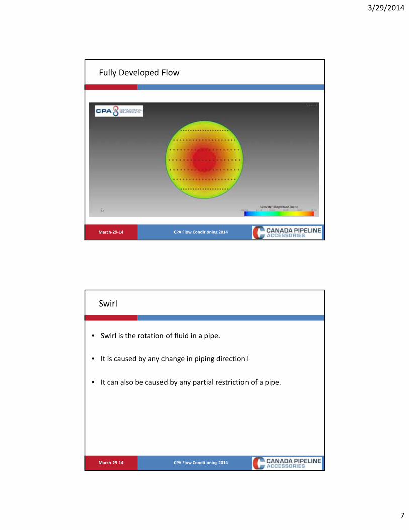
Fully Developed Flow
• Fully developed pipeline flow is the ideal state of a fluid in a pipe.
• If we had an infinitely long pipe, this is the flow we would always see.
• It is mathematically predictable.
• It is perfectly symmetrical around the center of the pipe.
• It has no swirl.
• This *should* guarantee us perfect, error free, repeatable measurement.
• Installation effects take us away from this state.
CPA Flow Conditioning 2014March‐29‐14
Fully Developed Flow
0
0.2
0.4
0.6
0.8
1
1.2
1.4
1.6
0 0.05 0.1 0.15 0.2 0.25 0.3
Norm
alized Flow Velocity (V/V
avg)
Distance Across Pipe (m)
30000000 3000000 300000 30000 15000 10000 6000 1000 300
3/29/2014
7
CPA Flow Conditioning 2014March‐29‐14
Fully Developed Flow
CPA Flow Conditioning 2014March‐29‐14
Swirl
• Swirl is the rotation of fluid in a pipe.
• It is caused by any change in piping direction!
• It can also be caused by any partial restriction of a pipe.

3/29/2014
8
CPA Flow Conditioning 2014March‐29‐14
Swirl
CPA Flow Conditioning 2014March‐29‐14
Swirl

3/29/2014
9
CPA Flow Conditioning 2014March‐29‐14
Swirl
CPA Flow Conditioning 2014March‐29‐14
Swirl

3/29/2014
10
CPA Flow Conditioning 2014March‐29‐14
Swirl
• Swirl causes unpredictable distortions in the flow profile that change over time.
• Swirl flattens and then inverts flow profiles due to centripetal force. The harder the fluid is spinning, the more energy that is pushed to the pipe walls.
• Swirl can cause local effects due to the location of pressure taps (dPmeasurement) or in the case of Ultrasonic Meters (adding to or subtracting to local path velocity).
CPA Flow Conditioning 2014March‐29‐14
Installation Effects
Every pipe fitting generates an installation effect.
• Tees
• Elbows
• Expanders
• Reducers
• Valves
• Probes
All of these objects can combine to create a deviation from perfect fully developed flow.

3/29/2014
11
CPA Flow Conditioning 2014March‐29‐14
Installation Effects ‐ Elbows
CPA Flow Conditioning 2014March‐29‐14
Installation Effects ‐ Tees

3/29/2014
12
CPA Flow Conditioning 2014March‐29‐14
Installation Effects – Tees
CPA Flow Conditioning 2014March‐29‐14
Installation Effects – Tees /w Turbulence

3/29/2014
13
CPA Flow Conditioning 2014March‐29‐14
Installation Effects ‐ Probes
CPA Flow Conditioning 2014March‐29‐14
Installation Effects – Valves

3/29/2014
14
CPA Flow Conditioning 2014March‐29‐14
Installation Effects – Elbows & Orifice Plates
CPA Flow Conditioning 2014March‐29‐14
Installation Effects – Reducers
3/29/2014
15
CPA Flow Conditioning 2014March‐29‐14
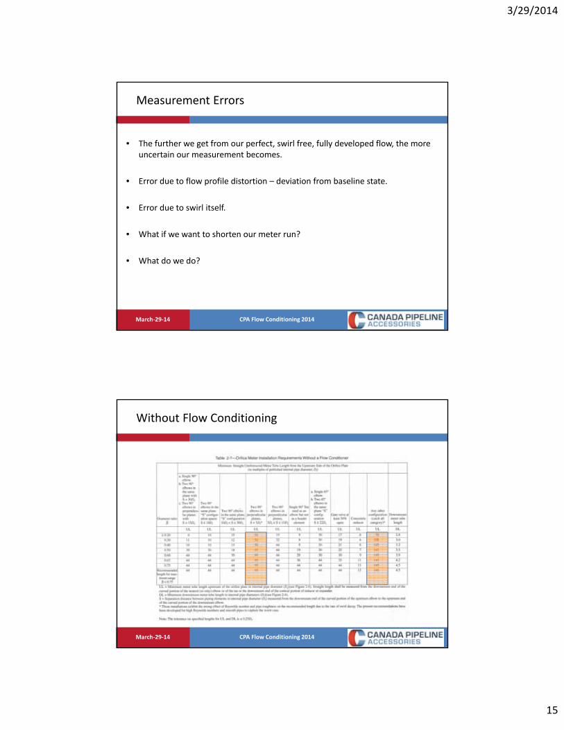
Measurement Errors
• The further we get from our perfect, swirl free, fully developed flow, the more uncertain our measurement becomes.
• Error due to flow profile distortion – deviation from baseline state.
• Error due to swirl itself.
• What if we want to shorten our meter run?
• What do we do?
CPA Flow Conditioning 2014March‐29‐14
Without Flow Conditioning

3/29/2014
16
CPA Flow Conditioning 2014March‐29‐14
Flow Conditioning
A properly designed Flow Conditioner converts this flow....
...Into this.
CPA Flow Conditioning 2014March‐29‐14
Flow Conditioning
A properly designed Flow Conditioner converts this flow....
...Into this.

3/29/2014
17
CPA Flow Conditioning 2014March‐29‐14
Flow Conditioning
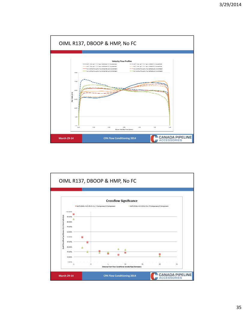
0.00
5.00
10.00
15.00
20.00
25.00
30.00
35.00
40.00
45.00
50.00
‐6.00 ‐4.00 ‐2.00 0.00 2.00 4.00 6.00
Empty 5&5 OIMLR137 25m 15000 Horizontal 2.5D Upstream Empty 5&5 OIMLR137 25m 15000 Vertical 2.5D Upstream
Empty 5&5 OIMLR137 25m 15000 Horizontal 1D Upstream Empty 5&5 OIMLR137 25m 15000 Vertical 1D Upstream
CPA Flow Conditioning 2014March‐29‐14
Flow Conditioning
0.00
5.00
10.00
15.00
20.00
25.00
30.00
‐6.00 ‐4.00 ‐2.00 0.00 2.00 4.00 6.00
CPA50E 10&10 OIMLR137 25m 11500 Horizontal 5D Downstream CPA50E 10&10 OIMLR137 25m 11500 Vertical 5D Downstream
CPA50E 10&10 OIMLR137 25m 11500 Horizontal 8D Downstream CPA50E 10&10 OIMLR137 25m 11500 Vertical 8D Downstream
CPA50E 10&10 OIMLR137 25m 11500 Horizontal 15D Downstream CPA50E 10&10 OIMLR137 25m 11500 Vertical 15D Downstream

3/29/2014
18
CPA Flow Conditioning 2014March‐29‐14
How They Work
• Hole pattern is arranged so that the resulting downstream condition is a fully developed profile, the same as would be achieved by a long length of straight, uniform pipe.
• Stream is forced towards the holes in the plate which forces the pressure field to balance immediately upstream of the flow conditioner.
• Fluid accelerates to over twice its initial velocity where the flow through each hole is roughly proportional to its area.
• If swirl is present, this is cut out by the acceleration of the gas, and the thickness of the plate.
CPA Flow Conditioning 2014March‐29‐14
0
0.2
0.4
0.6
0.8
1
1.2
0 0.05 0.1 0.15 0.2 0.25 0.3 0.35
Fluid Velocity (m/s)
Distance Across Pipe (m)
5 FPS 25 FPS 75 fps 75 FPS. P=52000 Pa 75 FPS, Rough Wall 75 FPS, Smooth Wall
How They Work

3/29/2014
19
CPA Flow Conditioning 2014March‐29‐14
Meter Types
• All volumetric flow meters can be flow conditioned: Orifice, Ultrasonic, Venturi, Coriolis Vortex, Turbine, Cone, Mag, etc.
• Every meter type responds differently to the effects of swirl and flow profile distortion.
• Volumetric flow meters are looking for ‘good flow’. Flow with minimal swirl and good flow profiles.
• A flow conditioner is simply trying to improve the flow that the meter is seeing.
CPA Flow Conditioning 2014March‐29‐14
CPA once said….
• It’s far easier to measure good flow with a bad meter, than trying to measure bad flow with a good meter.

3/29/2014
20
CPA Flow Conditioning 2014March‐29‐14
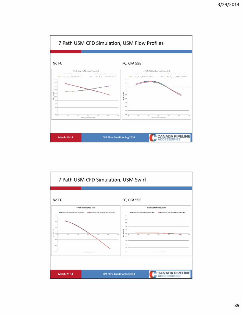
Ultrasonic Meters
• Rely on a noise pulse that is transmitted through the fluid and the flow rate is computed using the transit time.
• Transit time is affected by velocity disturbances within the pipe, slowing or speeding up the pulse.
• Multiple paths help to generate a complete picture of the cross sectional flow within the pipe.
• The meter only knows how long it took for the pulse to travel from point A to point B.
• It cannot guess the state of the flow along the way.
CPA Flow Conditioning 2014March‐29‐14
CFD Ultrasonic Simulation
• SawchukSonic™ CFD Ultrasonic Flow Meter
• 7 path layout (every 1/8 pipe diameter).
• 45 degree path angle.
• Dual, redundant meters (14 paths total).
• Ability to switch paths on and off at will to show effect on final flow meter output.
• Path layout, angle and weighting has not been optimized for accuracy, reynolds number shifts or ability to handle installation effects. Meter is for demonstration purposes only.

3/29/2014
21
CPA Flow Conditioning 2014March‐29‐14
Computational Fluid Dynamics (CFD)
CPA Flow Conditioning 2014March‐29‐14
Computational Fluid Dynamics (CFD)

3/29/2014
22
CPA Flow Conditioning 2014March‐29‐14
Computational Fluid Dynamics (CFD)
CPA Flow Conditioning 2014March‐29‐14
Computational Fluid Dynamics (CFD)

3/29/2014
23
CPA Flow Conditioning 2014March‐29‐14
Computational Fluid Dynamics (CFD)
CPA Flow Conditioning 2014March‐29‐14
Computational Fluid Dynamics (CFD)

3/29/2014
24
CPA Flow Conditioning 2014March‐29‐14
Computational Fluid Dynamics (CFD)
CPA Flow Conditioning 2014March‐29‐14
Computational Fluid Dynamics (CFD)

3/29/2014
25
CPA Flow Conditioning 2014March‐29‐14
Computational Fluid Dynamics (CFD)
CPA Flow Conditioning 2014March‐29‐14
Computational Fluid Dynamics (CFD)

3/29/2014
26
CPA Flow Conditioning 2014March‐29‐14
Computational Fluid Dynamics (CFD)
CPA Flow Conditioning 2014March‐29‐14
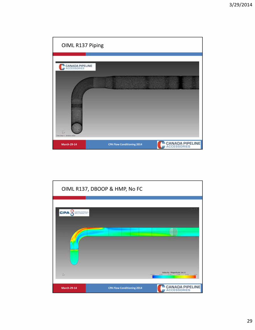
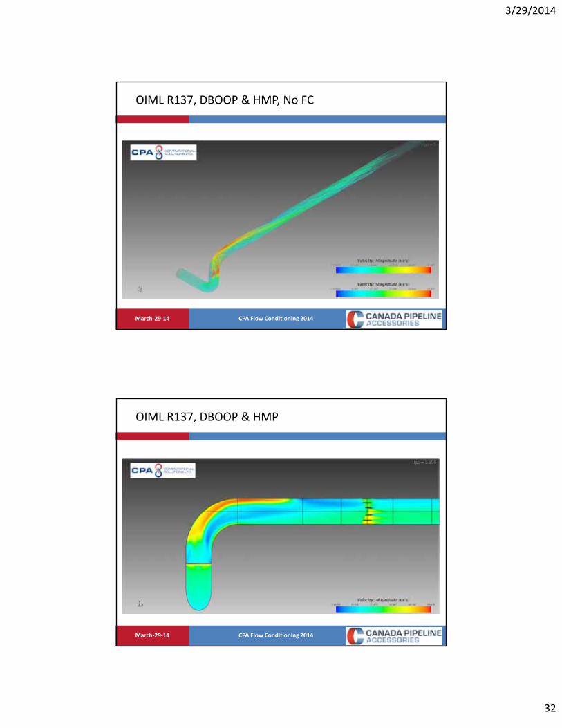
OIML R137 Piping
• Dual elbows/bends out of plane (DBOOP)
• Half moon plate separating the elbows. Opening is towards the outside of the turn radius.
• Expander at the meter run inlet is no longer used; the elbows are the same pipe diameter as the flow meter.

3/29/2014
27
CPA Flow Conditioning 2014March‐29‐14
OIML R137 Piping
CPA Flow Conditioning 2014March‐29‐14
OIML R137 Piping

3/29/2014
28
CPA Flow Conditioning 2014March‐29‐14
OIML R137 Piping
CPA Flow Conditioning 2014March‐29‐14
OIML R137 Piping
3/29/2014
29
CPA Flow Conditioning 2014March‐29‐14
OIML R137 Piping
CPA Flow Conditioning 2014March‐29‐14
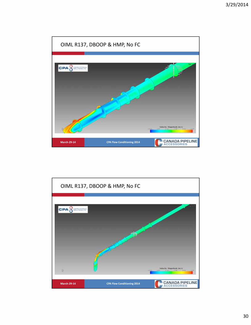
OIML R137, DBOOP & HMP, No FC
3/29/2014
30
CPA Flow Conditioning 2014March‐29‐14
OIML R137, DBOOP & HMP, No FC
CPA Flow Conditioning 2014March‐29‐14
OIML R137, DBOOP & HMP, No FC

3/29/2014
31
CPA Flow Conditioning 2014March‐29‐14
OIML R137, DBOOP & HMP, No FC
CPA Flow Conditioning 2014March‐29‐14
OIML R137, DBOOP & HMP, No FC
3/29/2014
32
CPA Flow Conditioning 2014March‐29‐14
OIML R137, DBOOP & HMP, No FC
CPA Flow Conditioning 2014March‐29‐14
OIML R137, DBOOP & HMP

3/29/2014
33
CPA Flow Conditioning 2014March‐29‐14
OIML R137, DBOOP & HMP
CPA Flow Conditioning 2014March‐29‐14
OIML R137, DBOOP & HMP

3/29/2014
34
CPA Flow Conditioning 2014March‐29‐14
OIML R137, DBOOP & HMP, No FC, 10D Downstream
CPA Flow Conditioning 2014March‐29‐14
OIML R137, DBOOP & HMP, CPA 55E, 10D Downstream
3/29/2014
35
CPA Flow Conditioning 2014March‐29‐14
OIML R137, DBOOP & HMP, No FC
CPA Flow Conditioning 2014March‐29‐14
OIML R137, DBOOP & HMP, No FC

3/29/2014
36
CPA Flow Conditioning 2014March‐29‐14
OIML R137, DBOOP & HMP, No FC
CPA Flow Conditioning 2014March‐29‐14
OIML R137, DBOOP & HMP, CPA 55E

3/29/2014
37
CPA Flow Conditioning 2014March‐29‐14
OIML R137, DBOOP & HMP, CPA 55E
CPA Flow Conditioning 2014March‐29‐14
OIML R137, DBOOP & HMP, CPA 55E

3/29/2014
38
CPA Flow Conditioning 2014March‐29‐14
7 Path USM CFD Simulation, Flow Profiles
No FC FC, CPA 55E
CPA Flow Conditioning 2014March‐29‐14
7 Path USM CFD Simulation, Swirl Profiles
No FC FC, CPA 55E
3/29/2014
39
CPA Flow Conditioning 2014March‐29‐14
7 Path USM CFD Simulation, USM Flow Profiles
No FC FC, CPA 55E
CPA Flow Conditioning 2014March‐29‐14
7 Path USM CFD Simulation, USM Swirl
No FC FC, CPA 55E

3/29/2014
40
CPA Flow Conditioning 2014March‐29‐14
7 Path USM CFD Simulation, 2 Path Error
No FC FC, CPA 55E
No FC, ‐1.29% CPA 55E, ‐2.38%
CPA Flow Conditioning 2014March‐29‐14
7 Path USM CFD Simulation, 3 Path Error
No FC FC, CPA 55E
No FC, ‐3.29% CPA 55E, 0.37%

3/29/2014
41
CPA Flow Conditioning 2014March‐29‐14
7 Path USM CFD Simulation, 4 Path Error
No FC FC, CPA 55E
No FC, 1.86% CPA 55E, ‐0.16%
CPA Flow Conditioning 2014March‐29‐14
7 Path USM CFD Simulation, 7 Path Error
No FC FC, CPA 55E
No FC, ‐0.41% CPA 55E, 0.07%

3/29/2014
42
CPA Flow Conditioning 2014March‐29‐14
USM Results, No FC
CPA Flow Conditioning 2014March‐29‐14
USM Results, CPA 55E

3/29/2014
43
CPA Flow Conditioning 2014March‐29‐14
Ultrasonic Meters
• Since ultrasonic meters cannot actually determine what the transducer pulse is seeing, we want to guarantee the best flow profile possible.
• A flow conditioner helps ensure that this is possible. It helps creates a reference state so that no matter what the upstream conditions are, the ultrasonic meter is measuring a more predictable and repeatable flow profile shape.
• Deviations from this baseline result in errors that add to the complexity of calculating flow rate.
CPA Flow Conditioning 2014March‐29‐14
• A properly designed flow conditioner is recommended for use in a range of Reynolds numbers.
• All fluid flows can improve from some sort of flow conditioning.
• While highly viscous flows are extremely resilient to swirl and flow profile distortions, the use of a flow conditioner quickly eliminates the remaining bulk rotation.
• What is the downside? How much pressure drop are we willing to spend?
Plate Based Isolating Flow Conditioners

3/29/2014
44
CPA Flow Conditioning 2014March‐29‐14
Flow Conditioning Swirl Removal
CPA Flow Conditioning 2014March‐29‐14
Flow Conditioning Swirl Removal

3/29/2014
45
CPA Flow Conditioning 2014March‐29‐14
Pressure Drop
• All fittings, obstructions, even pipe itself has a “k factor”.
• The k factor is the pressure loss coefficient for a particular piece of piping.
• It is experimentally determined using the measured pressure drop.
• K = Pressure loss coefficient.
• ΔP = Pressure drop across a section of pipe or a fitting.
• ρ = Bulk fluid density, kg/m3.
• V = Bulk fluid velocity, m/s.
2
2VkP
CPA Flow Conditioning 2014March‐29‐14
Pressure Drop
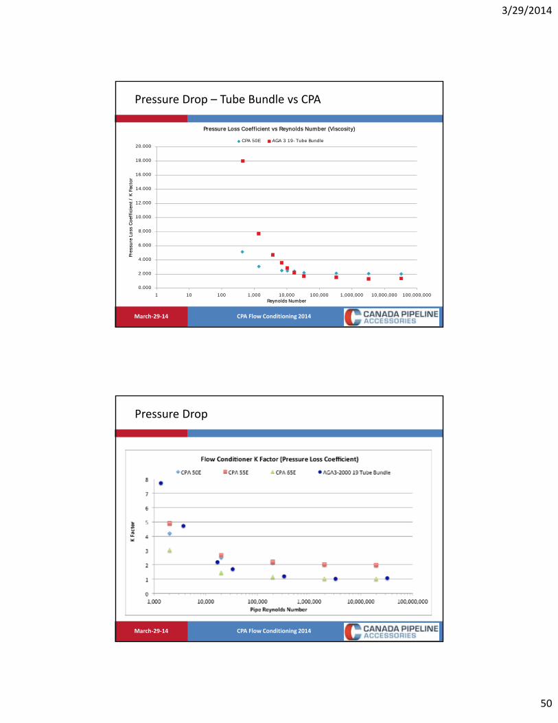
• For natural gas applications, most plate flow conditioners have a K factor of approximately 2.
• Tube bundles are closer to 0.75 – 1.5.
• What if we are worried about the pressure drop across the flow conditioner?

3/29/2014
46
CPA Flow Conditioning 2014March‐29‐14
Pressure Drop
• The CPA 50E K factor ~ 2.0 (dP same as roughly 277 feet of pipe, 12” ID).
• CPA 65E K factor ~ 1.0 (dP same as roughly 140 feet of pipe, 12” ID)
• Long radius Elbow K factor ~ 0.6 – 0.8
• Tee, flowing straight through ~0.5
• Tee, flow turning 90 degrees from inlet to outlet ~ 1.2 – 1.8
• Flow from a inlet header into a meter run ~ 1.0
• Flow from a meter run into an outlet header ~ 0.78
CPA Flow Conditioning 2014March‐29‐14
Pressure Drop
• The uni‐directional meter run on page 27 of AGA9, excluding the flow conditioner, will have a total K factor of at least 3.0 – 4.0.
• This is ignoring the fittings that would be needed to connect up to the tees.
• Adding two additional tees would nearly double the pressure drop.
• This is assuming fully developed flow. Swirl and profile distortion will change the pressure drop!

3/29/2014
47
CPA Flow Conditioning 2014March‐29‐14
Pressure Drop
CPA Flow Conditioning 2014March‐29‐14
Relative Pressure Drop

3/29/2014
48
CPA Flow Conditioning 2014March‐29‐14
Pressure Drop – Tube Bundle vs CPA
19‐Tube Bundle CPA 50E/55E CPA 65E
Wall Thickness (Inches) 0.125 0.25 0.298
Pipe Diameter (Inches) 11.938 11.938 11.938 11.938 11.938
Pipe Area (Inches^2) 111.932 111.932 111.932 111.932 111.938
Flow Area (Inches^2) 94.957 79.848 74.493 53.450 65.206
Porosity (%) 84.84% 71.34% 66.55% 47.75% 58.25%
CPA Flow Conditioning 2014March‐29‐14
• The 19‐Tube Bundle has multiple sets of fluid passages:
Surface Area

3/29/2014
49
CPA Flow Conditioning 2014March‐29‐14
• Per unit length (1”) the 19‐Tube Bundle used has about 287 In2 of wetted surface area.
• A plate flow conditioner such as the CPA 50E has 128 In2
Surface Area
CPA Flow Conditioning 2014March‐29‐14
• Most plate flow conditioners have a thickness of 10 – 20% of the pipe diameter.
• In a 12 Schedule 40 pipe, a 19‐Tube Bundle will have a length of twice the pipe NPS, giving a thickness of 25.5 inches, resulting in a overall wetted surface area of 7322 In2.
• Roughly 34 times the surface
area of a plate flow conditioner!
Surface Area…it gets worse.
3/29/2014
50
CPA Flow Conditioning 2014March‐29‐14
0.000
2.000
4.000
6.000
8.000
10.000
12.000
14.000
16.000
18.000
20.000
1 10 100 1,000 10,000 100,000 1,000,000 10,000,000 100,000,000
Pres
sure
Los
s Co
effic
ient
/ K
Fac
tor
Reynolds Number
Pressure Loss Coefficient vs Reynolds Number (Viscosity)
CPA 50E AGA 3 19-Tube Bundle
Pressure Drop – Tube Bundle vs CPA
CPA Flow Conditioning 2014March‐29‐14
Pressure Drop

3/29/2014
51
CPA Flow Conditioning 2014March‐29‐14
Plate Based Isolating Flow Conditioners
0
500
1000
1500
2000
2500
3000
3500
0 10 20 30 40 50 60 70 80 90 100
Tota
l Life
Cyc
le C
osts
(C
apita
l + O
pera
ting
+ C
ompr
essi
on)
Pipe Porosity or Pipe Open Area (%)
Capital Cost Driven(Longer Meter Stations)
Fuel Gas Driven(Compression Costs To
Overcome Severe PressureDrop)
Optimal Flow Conditioner Porosity
CPA Flow Conditioning 2014March‐29‐14
Measurement Value Graph
3/29/2014
52
CPA Flow Conditioning 2014March‐29‐14
Flow Conditioning Conclusion
• Can eliminate up to 80 – 90% of pipeline swirl.
• Help restore flow profile symmetry and eliminate distortions.
• Isolates the flow meter from upstream disturbances.
• Allows much shorter meter runs to be used with much higher repeatability.
• Are applicable for all liquid or gas flows!
The flow conditioner is merely helping out the meter, providing higher reproducibility and lower uncertainty!
CPA Flow Conditioning 2014March‐29‐14
Thank You
• For Further information
www.flowconditioner.com
www.cpacfd.com
Danny Sawchuk
403.236.4480