THERMOX · wdg-ivc / 0-500 ppm 1 cem/humox wdg-ivc/iq / 0-500 ppm 1 wdg-ivcm/iq / 0-500 ppm 1, ...

- 1 -
FLUE GAS ANALYSIS SYSTEM
CEM-500
USERS MANUAL

- 1 -
1. System Overview
1.1 System introduction
CEM-500 type flue gas emissions on-line monitoring system is a combination of the world's most
advanced online analytical techniques and environmental monitoring special requirements, combined
with my company for many years in the field of industrial processes and environmental monitoring in
the field of accumulated rich experience. It can be applied to the on-line monitoring of gaseous
pollutants (SO2, NOx, CO, CO2, O2) in flue gas as well as temperature, pressure and flow rate (T,P.F are
optional). The data acquisition and processing system can generate diagram curve and environmental
reports (optional), which is fully meet the government standard of Environmental Bureau of
“Specifications and Test Procedures for Continuous Emission Monitoring Systems of Flue Gas Emitted
from Stationary Sources”.
1.2 The scope of application
This system is applicable to thermal power plant boilers, industrial & civil boilers & industrial kilns and
fixed pollution source flue gas CEMS with solid fuel or raw material as fuel or raw material.
1.3 Working environment
Ambient temperature: -5 ℃ ~ 40 ℃, to avoid direct sunlight and close to the heat source;
Air-conditioning from -15 ℃ ~ 40 ℃ or -5 ℃ ~ 50 ℃
Atmospheric pressure: 86 ~ 106KPa
Relative humidity: ≤90%
Flue gas temperature: <500 ℃
There is no strong vibration on site, the maximum vibration does not exceed 100Hz, 0.3m / s2.
1.4 Facilities
Power: 220V AC 50Hz
Startup power: 5KVA (single set, with heating pipe does not exceed 30 meters)
Working power: 3KVA (single set, with heat pipe does not exceed 30 meters)
Gas source: Compressed air , 0.4 ~ 0.8MPa clean, no oil, no water
Compressed air consumption: less than 20L / h (based on the actual dust content of the site
smoke)
Water requirement: None
Others: The equipment room requires the installation of ventilation equipment, dust-proof
facilities, air-conditioning equipment, lighting equipment and so on.
2. System Details
2.1 Working principle
CEM-500 flue gas emissions on-line monitoring system is a combination of heating extraction
sampling + non-dispersive infrared absorption measurement principle. The flue gas collected by the
heated sampling probe goes through heated sampling tube and two dehydrations, then inlet the
analyzer. Stainless steel sampling probe with built-in particles filter (filter element made of titanium
sintered), can remove the diameter of more than 2 m of particles from the sample gas, to avoid
- 2 -
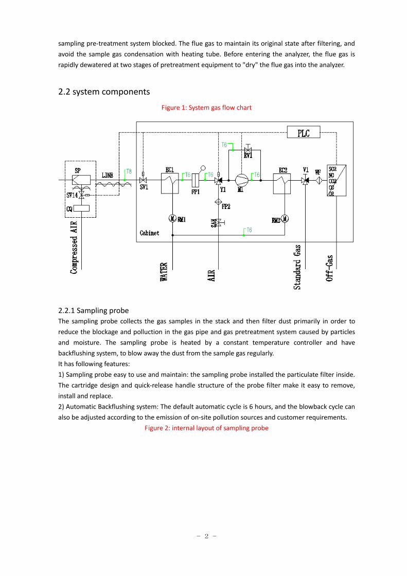
sampling pre-treatment system blocked. The flue gas to maintain its original state after filtering, and
avoid the sample gas condensation with heating tube. Before entering the analyzer, the flue gas is
rapidly dewatered at two stages of pretreatment equipment to "dry" the flue gas into the analyzer.
2.2 system components
Figure 1: System gas flow chart
2.2.1 Sampling probe
The sampling probe collects the gas samples in the stack and then filter dust primarily in order to
reduce the blockage and polluction in the gas pipe and gas pretreatment system caused by particles
and moisture. The sampling probe is heated by a constant temperature controller and have
backflushing system, to blow away the dust from the sample gas regularly.
It has following features:
1) Sampling probe easy to use and maintain: the sampling probe installed the particulate filter inside.
The cartridge design and quick-release handle structure of the probe filter make it easy to remove,
install and replace.
2) Automatic Backflushing system: The default automatic cycle is 6 hours, and the blowback cycle can
also be adjusted according to the emission of on-site pollution sources and customer requirements.
Figure 2: internal layout of sampling probe

- 3 -
1. calibration port
2. filter element handle: anticlockwise rotate it to bring out of the filter element.
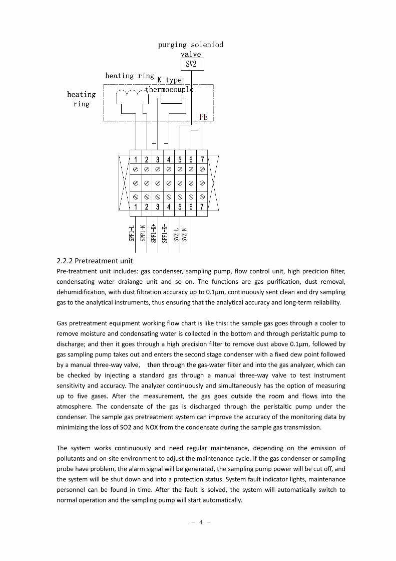
3. purging solenoid valve: DC24V, 6.9W, G1/2 connector
4. Heated tube inlet
5. Wiring terminal
Figure 3: electricity wiring of sampling probe
- 4 -
2.2.2 Pretreatment unit
Pre-treatment unit includes: gas condenser, sampling pump, flow control unit, high precicion filter,
condensating water draiange unit and so on. The functions are gas purification, dust removal,
dehumidification, with dust filtration accuracy up to 0.1μm, continuously sent clean and dry sampling
gas to the analytical instruments, thus ensuring that the analytical accuracy and long-term reliability.
Gas pretreatment equipment working flow chart is like this: the sample gas goes through a cooler to
remove moisture and condensating water is collected in the bottom and through peristaltic pump to
discharge; and then it goes through a high precision filter to remove dust above 0.1μm, followed by
gas sampling pump takes out and enters the second stage condenser with a fixed dew point followed
by a manual three-way valve, then through the gas-water filter and into the gas analyzer, which can
be checked by injecting a standard gas through a manual three-way valve to test instrument
sensitivity and accuracy. The analyzer continuously and simultaneously has the option of measuring
up to five gases. After the measurement, the gas goes outside the room and flows into the
atmosphere. The condensate of the gas is discharged through the peristaltic pump under the
condenser. The sample gas pretreatment system can improve the accuracy of the monitoring data by
minimizing the loss of SO2 and NOX from the condensate during the sample gas transmission.
The system works continuously and need regular maintenance, depending on the emission of
pollutants and on-site environment to adjust the maintenance cycle. If the gas condenser or sampling
probe have problem, the alarm signal will be generated, the sampling pump power will be cut off, and
the system will be shut down and into a protection status. System fault indicator lights, maintenance
personnel can be found in time. After the fault is solved, the system will automatically switch to
normal operation and the sampling pump will start automatically.

- 5 -
Figure 4: Gas pretreatment panel
1. sample gas flow
2. switch valve for meausurement and calibration
3. span point calibration
4. calibration gas flow
5. sample gas bypass adjust
6. calibration gas inlet
7. calibration gas bypass adjust
2.2.3 Control Unit
The system adopts S7-200 PLC module. It can connect DCS systems for monitoring, automated data
processing and remote transfer.
The CEM-500 output signals include: fault, calibration error, power failure, maintenance, range
indication, and calibration. In addition, it has the function of holding data before calibration.
Figure 5: PLC control panel
1. Auto/ maintenance switch
2. sampling pump indication and pumping manually
3. heated tube temperature control
4. sampling probe temperature control
5. Purging indication and purging manually
6. Alarm indication
2.2.4 Analysis Unit
The analysis unit of the CEM-500 is the ZRE infrared analyzer manufactured by Fuji of Japan. The

- 6 -
concentration of SO2, NO, CO and CO2 is determined by non-dispersive infrared absorption technique.
The concentration of O2 is determined by electrochemical technique.
Gas Analyzer
Continuous monitoring of 5 flue gas components in one analyzer.
Human-machine interface friendly: LCD display, adjustable backlight, simple operation, fast
programming, menu operation (programming, testing and calibration, etc.), easy maintenance
and automatic calibration. Two scale ranges can be set in the measurement range which can be
overrun automatic switching.
Sample gas chamber with a unique removable technology, removable cleaning.
It uses zero-point air calibration to reduce zero drift, making long-term operation more stable.
Air can be used as the standard gas for calibration of oxygen.
2.3 System main components
Picture Function
Name: stop valve
Function: stop purging
Parameter:
Valve type: normally closed solenoid valve
Power supply: DC24V, 6W
Interface specification: G1/4.
Name: sampling pump
Function: sampling the gas
Parameter:
Pump type: diaphragm pump
Power supply: AC220, 60W
Flow rate: 5.5L/min
Working pressure: -160mbar~2.5bar
- 7 -
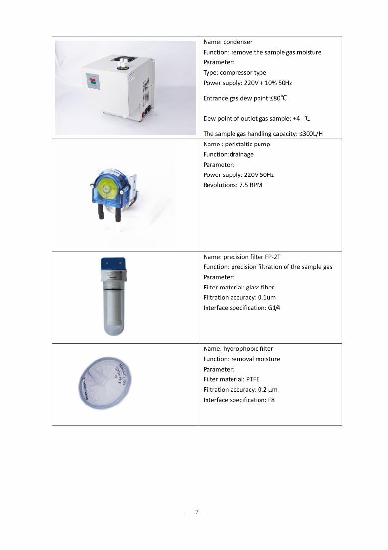
Name: condenser
Function: remove the sample gas moisture
Parameter:
Type: compressor type
Power supply: 220V + 10% 50Hz
Entrance gas dew point:≤80℃
Dew point of outlet gas sample: +4 ℃
The sample gas handling capacity: ≤300L/H
Name : peristaltic pump
Function:drainage
Parameter:
Power supply: 220V 50Hz
Revolutions: 7.5 RPM
Name: precision filter FP-2T
Function: precision filtration of the sample gas
Parameter:
Filter material: glass fiber
Filtration accuracy: 0.1um
Interface specification: G1/4
Name: hydrophobic filter
Function: removal moisture
Parameter:
Filter material: PTFE
Filtration accuracy: 0.2 μm
Interface specification: F8

- 8 -
Name: three-way solenoid valve
Function: air/calibration gas switch
Parameter:
Soleniod material: three way
Power supply: DC24V,6W
Interface specification: G1/4
3. System technical parameters
3.1 Pre-treatment unit technical parameters
Cabinets: size 800 * 600 * 2100, the cabinet is made of 2mm steel electrostatic spraying
Control system: Siemens PLC, automatic backflushing system, sampling, drainage, eliminating
manual maintenance
Sampling pump: The German KNF pump, sample gas extraction volume ≥ 4L / min, stable
operation for a long time to ensure that the system response time
Dust removal: Adopt titanium alloy filter in the sampling probe to remove dust above 2um; then
through the secondary filter, the filtration precision can reach 0.1um to reach the requirement of
gas analyzer, then through the hydrophobic filter (0.2 um) to ensure the stable operation of the
analyzer
Removal moisture: the sample gas into the condenser, the rapid removal of gas in the sample gas,
and the use of peristaltic pump automatic drainage; and then into the condenser secondary
condensation to further ensure the dehydration
Protection: Sampling probe, heating pipe and condenser have alarm function. When the system
heats up and the condenser is in abnormal water removal, the alarm signal will be transmitted to
the PLC to cut off the system operation and ensure the safe use of the analyzer. Alarm signal.
3.2 Gas analyzer specifications
Measurement components: SO2, NO, CO, CO2, O2
Measurement methods: SO2, NO, CO, CO2 --- non-dispersive infrared absorption method (NDIR)
O2 --- electrochemical method
Measuring range: SO2:0-1500mg/m3, NOx:0-400mg/m3, O2:0-25%, CO:0-250mg/3, CO2:0-50%
Measurement accuracy: ≤ 2% FS
Response time: ≤60s
Automatic calibration: The instrument built-in automatic zero adjustment device can be
automatically calibrated without standard gas zero
Power supply: AC180 ~ 240V, 50Hz, 60W
Output signal: standard RS-232/485, DC 4 ~ 20mA current output;
- 9 -
Dimensions: 482.6mm (19 ") * 390mm * 132mm (3U)
Instrument weight: about 12kg
Operating temperature: 5 ℃ ~ 45 ℃
Relative humidity: <90% RH
Atmospheric pressure: 85 ~ 105 Kpa
4. System installation
4.1 Sampling point selection
Monitoring sampling points should be selected downstream of the emission control equipment
of solid pollution source; vertical pipe section and stack negative pressure area should be
selected first; and the location of stack bend and the section with sharp changes should be
avoided. Monitoring sampling points need to build a monitoring platform to facilitate the
installation and maintenance of technical staff, monitoring platform easy to reach, there is
enough space for routine maintenance and comparison monitoring. When the sampling platform
is set at a height of ≥5 meters from the ground, there should be a Z-ladder / escalator / elevator
leading to the platform.
Monitoring sampling points need to open two flange holes (main sampling hole, test comparison
hole). If it is positive pressure, need to install gate valve and sleeve.
Flange welding must coincide with the vertical direction, in accordance with the flue gas flow
Flange welding point in the center of the flue, some flange can be adjusted accordingly. The
distance between the flanges should be greater than 50cm, depending on the site conditions.
Flange welding must be anti-acid corrosion treatment
4.2 Monitoring equipment workshop construction
The equipment should be set up in a safe place close to the sampling points of the monitoring
and shall be built with brick and concrete structures with the indoor area of not less than 10
square meters.
Should install exhaust fan and air-conditioner
Standard security door, the door width of not less than 800mm.
4.3 System of strong electrical installation
The system's strong power requirements for the power supply single-phase 220V, 20A, 5KW
must be equipped with ground protection. Use three-core power cord 4 square cable. Harsh
environment can be laid through the pipe laying, pipe material through the seamless steel pipe,
the size is greater than φ24.
Distribution box selection of well-known brand air switch, and with leakage protector.
The lightning protection device must be installed on site.
Note: The power from the factory to the equipment room, the equipment room must be
installed between the ground protection
4.4 System weak electrical installation

- 10 -
The system uses a structured design, installation of weak systems outside the equipment room
only 4-core shielded cable routing.
The signal input part (referring to the inter-device sampling probe and monitoring host computer
and the communication between the monitoring part): 4-core shielded cable as the transmission
medium from the monitoring platform to the analytical instrument. Specific alignment to be
determined at the scene, should pay attention not to be co-laying with strong electricity, the use
of pipe or bridge laying.
Signal output part: 4-20mA standard current output or RS485 communication interface.
4.5 Clean gas requirement
Flue gas automatic monitoring equipment is a high-precision optical analysis instrument. To
ensure the long-term stable operation of the monitoring instrument, the monitoring and analysis
data are accurate and effective. The instrument must be clean and not contaminated. Therefore,
it is required to provide the gas source for cleaning the instrument.
Compressed gas source is provided by the factory and requires the clean gas source to be
transported to the equipment room by the gas pipe.
Gas source requirements: gas source of oil-free, anhydrous, non-suspended particulate matter,
pressure to the equipment room is not less than 0.4MPa.
If there is no compressed air source in the factory, it is suggested to purchase air compressed air
pump for clean air supply.
Gas source to the equipment room provided by the factory
Request the factory to complete the above five items in the system project before the
installation of the technical requirements.
4.6. System installation
Step 1: Install the sampling probe.
Step 2: The steel pipe or bridge is set up between the work platform and the equipment. The
sample heated tube and the cable are laid through steel pipe or bridge.
Step 3: heated tube connects to sampling probe; the other end should be equipped with exproof
terminal, sampling probe electricity wirings
Step 4: Heat tube goes into the cabinet and use the bracket to fix it throught the inlet of SV1
(stop valve)
Step 5: Connect the heat tube control line and the heat tube belt with 4mm2 wire and connect it
well.
Step 6: Insert the temperature sensor of heat tube and be close to the sampling pipe;
Step 7: All the signal lines enter the cabinet and enter the electrical backplane along the upper
lead frame and connect to the X2 terminal pile according to the label;
Step 8: Connect Power supply of the sampling probetos X3 terminal pile;
Step 9: System cabinet main power cable into the cabinet according to the drawings of X3
wiring pile;
Step 10: Connect the exhaust and drain lines (leading to the outdoors).
4.7 Power on and test
Test sampling probe and the analyzer calibration after 24 hours of stable operation

- 11 -
5. System operation
Instrument operation
After powering on, operate air switch as following.
Step Air switch number Function
Step 1: ZK1 The main power supply in the cabinet
Step 2: ZK9 Power supply of heat tube
Step3: ZK3 Power supply for sampling probe
Step4: ZK8 Power supply for cabinet lights
Step5: ZK2 Power supply of cooler
Step6: ZK4 Power supply for gas analyzer
Step7: ZK5 PLC controller power supply
Step8: ZK6 Power supply for 24V switching power supply
Step9: ZK7 Power supply for inspection power socket
According to the above steps to open the air switch, power on the analyzer, the system enters
into the working state.
The instrument calibration: after the stable operation of the equipment, connect the calibration
gas with instrument interface, using the calibration function (see the operation manual of the
analyzer).
6.Daily inspection, common faults and Solutions
6.1Daily precautions
For the field data timely view, abnormal timely contact with the manufacturer, the manufacturer
will be rushed to the scene within 24 hours of maintenance.
The utility condition to keep the normal indoor instrument (lighting, air conditioning, ventilation
etc.).
The sample gas and standard gas are toxic and harmful gases, beware of leakage!!! When the
standard gas is not used, the main valve of the gas cylinder should be closed. Pay attention to
maintaining a good indoor ventilation environment.
If have not use instrument for a long time, pls use clean air blowing pipe 5 - 10 minutes to ensure
that no corrosive gas in the gas analyzer, and then cut off all power, and careful storage, avoid
sunlight or humidity
Please use the power for the system with rated specifications, otherwise it may cause a fire or
system abnormal work.
Please make sure the system or equipment on the ground according to the provisions of the
construction, otherwise it may cause electric shock or abnormal instrument.
The system for the stack is strictly prohibited without permission to adjust and move.
The operation of the equipment must ensure that the sample gas already removed water, dust
and oil and other pre-processing operation, otherwise affect the accuracy of measurement
instrument. If condensate discharged from the drain pipe is corrosive and should be discharged
to the safety drain.
The equipment in diagnostic or testing condition, please do not turn on or turn off the
- 12 -
instrument power, otherwise it will damage the equipment
The instrument calibration must be in accordance with the instructions, in order to ensure the
accuracy of measurement instrument.
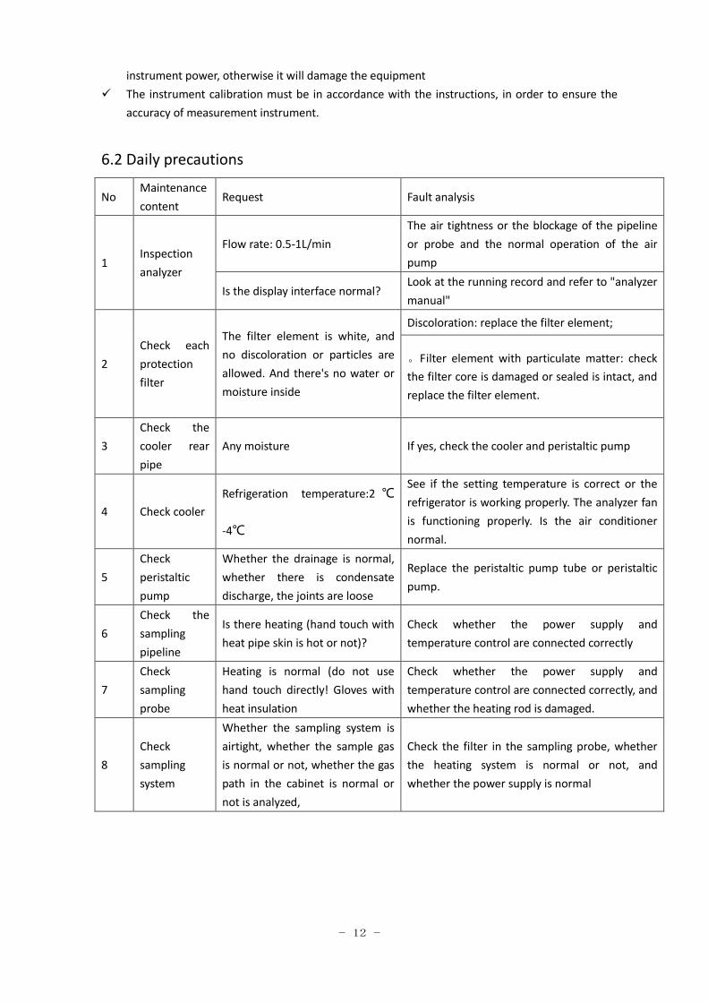
6.2 Daily precautions
No Maintenance
content Request Fault analysis
1 Inspection
analyzer
Flow rate: 0.5-1L/min
The air tightness or the blockage of the pipeline
or probe and the normal operation of the air
pump
Is the display interface normal? Look at the running record and refer to "analyzer
manual"
2
Check each
protection
filter
The filter element is white, and
no discoloration or particles are
allowed. And there's no water or
moisture inside
Discoloration: replace the filter element;
。Filter element with particulate matter: check
the filter core is damaged or sealed is intact, and
replace the filter element.
3
Check the
cooler rear
pipe
Any moisture If yes, check the cooler and peristaltic pump
4 Check cooler
Refrigeration temperature:2 ℃
-4℃
See if the setting temperature is correct or the
refrigerator is working properly. The analyzer fan
is functioning properly. Is the air conditioner
normal.
5
Check
peristaltic
pump
Whether the drainage is normal,
whether there is condensate
discharge, the joints are loose
Replace the peristaltic pump tube or peristaltic
pump.
6
Check the
sampling
pipeline
Is there heating (hand touch with
heat pipe skin is hot or not)?
Check whether the power supply and
temperature control are connected correctly
7
Check
sampling
probe
Heating is normal (do not use
hand touch directly! Gloves with
heat insulation
Check whether the power supply and
temperature control are connected correctly, and
whether the heating rod is damaged.
8
Check
sampling
system
Whether the sampling system is
airtight, whether the sample gas
is normal or not, whether the gas
path in the cabinet is normal or
not is analyzed,
Check the filter in the sampling probe, whether
the heating system is normal or not, and
whether the power supply is normal

- 13 -
6.3 Common faults and treatment methods
Fault phenomenon Fault reason Solutions
no response after
power on
No power supply;
Power line damage;
Fuse tube fuse.
Power supply, replace the power
outlet;
Replace damaged parts (insurance
pipe in the power line below the
socket holder)
After power on
system, the screen
back light, but no
image or image
display screen, white
light
The influence of environmental
temperature on LCD screen (which is
caused by the influence of voltage);
LCD screen contrast setting is not
normal.
After the instrument normally started,
the screen contrast can be adjusted by
left or right key in standby mode until
the best display effect is achieved.
Small flow or no flow
Sampling system fault;
Sampling port leakage;
Blockage of exhaust port or exhaust
pipe.
Check the sampling system and
eliminate external faults;
Tighten the sampling port to connect
the gas pipe and replace the sampling
tube;
Check the exhaust port; replace the
exhaust pipe.
The measured
numerical response is
slow and the
measured values
change little or no
change
Gas leakage of sampling gas path;
Dust filter clogging;
The heat tracing tube is not
accompanied by heat;
The sampling probe does not contain
heat
Check the sampling system and refer
to the "flow less or no flow"
processing method;
Replacing dust filter paper;
Check the heating line and sampling
probe to keep the heat tracing state
The magnitude of the
measured value is
larger than the
allowable error
The instrument is not preheated
enough;
Sampling instability
Normal instruments start and preheat
(15-30 minutes);
Check sampling system.
After measurement,
the value does not
return to zero
The gas circuit with residual gas;
Influence of instrument zero drift.
Perform measurements to remove
residual gas through nitrogen or clean
air; continuous air measurement for 5
minutes.
Perform zero adjustment or (and) user
calibration.
The deviation of
standard gas data is
larger
The analyzer was contaminated;
There is some water content in
sample gas;
Exception of pretreatment system;
Calibration error;
Output port factory error.
Check the condenser for proper
operation;
Each filter is tested for normal or not;
Peristaltic pump detection;
Re calibration;
Re search output port

- 14 -
Fault phenomenon Fault reason Solutions
Water vapor in the
rear pipe of cooler
。The pump is not in the normal
position should be adjusted;
Pump damage should be replaced
The refrigerator and peristaltic pump
should be inspected;
Especially to check the peristaltic
pump pump.
Protection filter dust
accumulation
The main cause of dust accumulation
is the damage of the filter of the
sampling probe
Check, clean or replace in time.
Discoloration of
protective filters
Plugging of sampling
pipeline
Probe heating and abnormal heating
of sampling tube;
Compressor condenser abnormal;
Abnormal operation of peristaltic
pump;
Check the power supply of the probe
and the sample tube;
Check cooler;
Check the peristaltic pump or pump;
Timely replacement.
Refrigerator
temperature
controller abnormal
Cooler damage;
Temperature controller damage;
Damage to the safety pipe;
Cold chamber damage
Replace all instrument fittings.
Trouble light
Check the working temperature of
the refrigerator, such as near the
room temperature, the refrigerator
damage.
Check the probe heating
temperature, such as the
temperature close to the normal
temperature, indicating that the
probe heating failure
Inform Supplier maintenance.
7.Transportation and storage
In the process of transportation and storage, the instrument should be rainproof, shockproof, anti
inversion Spare Parts
Item Name Remark Qty
1 Filter element Precision filter 4pcs
2 (ΦF6×1)PTFE tube tube
tube
Gas Analysis 10m
3 Filter element Sampling Probe 1pc
4 Peristatic pump pipe For persitatic 4pcs