
Flowpoint and SSR DSL Devices (3571) - CA...
54
Flowpoint and SSR DSL Devices Device Management Supports Management Module SM-CSI1096
Transcript of Flowpoint and SSR DSL Devices (3571) - CA...
Flowpoint and SSR DSL Devices
Device Management
Supports Management Module SM-CSI1096
D e v i c e M a n a g e m e n t Page 2 F l o w p o i n t a n d S S R D S L D e v i c e s
Copyright NoticeDocument 3571. Copyright © 2002-present by Aprisma Management Technologies, Inc. All rights reserved worldwide. Use, duplication, or disclosure by the United States government is subject to the restrictions set forth in DFARS 252.227-7013(c)(1)(ii) and FAR 52.227-19.
Liability DisclaimerAprisma Management Technologies, Inc. (“Aprisma”) reserves the right to make changes in specifications and other information contained in this document without prior notice. In all cases, the reader should contact Aprisma to inquire if any changes have been made.The hardware, firmware, or software described in this manual is subject to change without notice.IN NO EVENT SHALL APRISMA, ITS EMPLOYEES, OFFICERS, DIRECTORS, AGENTS, OR AFFILIATES BE LIABLE FOR ANY INCIDENTAL, INDIRECT, SPECIAL, OR CONSEQUENTIAL DAMAGES WHATSOEVER (INCLUDING BUT NOT LIMITED TO LOST PROFITS) ARISING OUT OF OR RELATED TO THIS MANUAL OR THE INFORMATION CONTAINED IN IT, EVEN IF APRISMA HAS BEEN ADVISED OF, HAS KNOWN, OR SHOULD HAVE KNOWN, THE POSSIBILITY OF SUCH DAMAGES.Trademark, Service Mark, and Logo InformationSPECTRUM, IMT, and the SPECTRUM IMT/VNM logo are registered trademarks of Aprisma Management Technologies, Inc., or its affiliates. APRISMA, APRISMA MANAGEMENT TECHNOLOGIES, the APRISMA MANAGEMENT TECHNOLOGIES logo, MANAGE WHAT MATTERS, DCM, VNM, SpectroGRAPH, SpectroSERVER, Inductive Modeling Technology, Device Communications Manager, SPECTRUM Security Manager, and Virtual Network Machine are unregistered trademarks of Aprisma Management Technologies, Inc., or its affiliates. For a complete list of Aprisma trademarks, service marks, and trade names, go tohttp://www.aprisma.com/manuals/trademark-list.htm.All referenced trademarks, service marks, and trade names identified in this document, whether registered or unregistered, are the intellectual property of their respective owners. No rights are granted by Aprisma Management Technologies, Inc., to use such marks, whether by implication, estoppel, or otherwise. If you have comments or concerns
about trademark or copyright references, please send an e-mail to [email protected]; we will do our best to help.Restricted Rights Notice(Applicable to licenses to the United States government only.)
This software and/or user documentation is/are provided with RESTRICTED AND LIMITED RIGHTS. Use, duplication, or disclosure by the government is subject to restrictions as set forth in FAR 52.227-14 (June 1987) Alternate III(g)(3) (June 1987), FAR 52.227-19 (June 1987), or DFARS 52.227-7013(c)(1)(ii) (June 1988), and/or in similar or successor clauses in the FAR or DFARS, or in the DOD or NASA FAR Supplement, as applicable. Contractor/manufacturer is Aprisma Management Technologies, Inc. In the event the government seeks to obtain the software pursuant to standard commercial practice, this software agreement, instead of the noted regulatory clauses, shall control the terms of the government's license.
Virus DisclaimerAprisma makes no representations or warranties to the effect that the licensed software is virus-free.Aprisma has tested its software with current virus-checking technologies. However, because no antivirus system is 100 percent effective, we strongly recommend that you write-protect the licensed software and verify (with an antivirus system in which you have confidence) that the licensed software, prior to installation, is virus-free.Contact InformationAprisma Management Technologies, Inc.273 Corporate DrivePortsmouth, NH 03801Phone: 603-334-2100U.S. toll-free: 877-468-1448Web site: http://www.aprisma.com
D e v i c e M a n a g e m e n t Page 3 F l o w p o i n t a n d S S R D S L D e v i c e s
ContentsINTRODUCTION 5
Purpose and Scope ........................................................5Required Reading ...........................................................5Supported Devices..........................................................6The SPECTRUM Model ..................................................7
TASKS 8
DEVICE VIEWS 10
Interface Device View ...................................................10Interface Icon.............................................................11
Interface Icon Subviews Menu...............................12Interface Status View ....................................................12Secondary Address Panel ............................................13
DEVICE TOPOLOGY VIEWS 14
APPLICATION VIEWS 15
Main Application View...................................................15Common Applications................................................16
Supported Applications .................................................17SSR Download Application ...........................................17
Download/Upload Information View ..........................17SSRetherApp ................................................................20
Ethernet Information View .........................................20Ethernet NAT Information View.................................22
Ethernet IP Translation Information View.................. 22SSRsystemApp............................................................. 23
System Information View...........................................23CallerID/UDP Relay Information View.......................26DHCP Server Option View ........................................ 26DHCP Server Global Option View............................. 27DHCP Server Subnet View ....................................... 27DHCP Server Subnet Option View............................ 28DHCP Server Client View.......................................... 28DHCP Server Client Option View .............................. 29Directory Information View ........................................ 29
SSRwanApp.................................................................. 29WAN Information View .............................................. 30DOD Operation/Bridging View................................... 31Remote IP Network Information View .......................31Phone/Call ID Information View ................................ 31
Phone Information Table ....................................... 32Call ID Table .......................................................... 32
Remote MAC View .................................................... 32Remote IPX Network Table View .............................. 32Remote IPX SAP Table View .................................... 33IP Filter Table View ................................................... 33IPX Filter Table View................................................. 34Callers Table View .................................................... 34Server IP Translation Table View.............................. 34DOD NAT Host Mapping Table View ........................ 34POTS Information View.............................................35
C o n t e n t s C o n t e n t s
D e v i c e M a n a g e m e n t Page 4 F l o w p o i n t a n d S S R D S L D e v i c e s
POTS Interface Information View ..............................36IP Information View ...................................................37Login Information View ..............................................37ISDN Information View ..............................................38
PERFORMANCE VIEWS 41
Device Performance View.............................................42Port Performance View .................................................42
CONFIGURATION VIEWS 43
Device Configuration View............................................43Interface Configuration View.........................................44DOD Configuration View...............................................44
MODEL INFORMATION VIEWS 49
INDEX 50
D e v i c e M a n a g e m e n t Page 5 F l o w p o i n t a n d S S R D S L D e v i c e s
Introduction
This section introduces SPECTRUM Device Management documentation for the FlowPoint and SmartSwitch Router (SSR) Digital Subscriber Line (DSL) devices.
This introduction contains the following topics:
• Purpose and Scope • Required Reading • Supported Devices (Page 6) • The SPECTRUM Model (Page 7)
Purpose and ScopeUse this document as a guide for managing the FlowPoint and SmartSwitch Router (SSR) Digital Subscriber Line (DSL) devices described on Page 6 with SPECTRUM management module SM-CSI1096. This document describes the icons, menus, and views that enable you to remotely monitor, configure, and troubleshoot FlowPoint and SmartSwitch Router (SSR) Digital Subscriber Line (DSL) devices through software models in your SPECTRUM database.
Information specific to SM-CSI1096 is what is primarily included in this document. For general
information about device management using SPECTRUM and explanations of SPECTRUM functionality and navigation techniques, refer to the topics listed under Required Reading
Required ReadingTo use this documentation effectively, you must be familiar with the information covered by the other SPECTRUM online documents listed below.
• Getting Started with SPECTRUM for Operators
• Getting Started with SPECTRUM for Administrators
• How to Manage Your Network with SPECTRUM
• SPECTRUM Views
• SPECTRUM Menus
• SPECTRUM Icons
I n t r o d u c t i o n S u p p o r t e d D e v i c e s
D e v i c e M a n a g e m e n t Page 6 F l o w p o i n t a n d S S R D S L D e v i c e s
• SPECTRUM Software Release Notice
Supported DevicesThe SPECTRUM management module SMCSI1096 currently allows you to model several different types of Flowpoint and SSR devices as described below.
Flowpoint 128 - ISDN/IDSL Router which offers 128Kbps data transfer rates and Mul-tiuser LAN sharing of ISDN services.
Flowpoint 144 - IDSL Router that provides data rates of 128 and 144 Kbps and Multiuser LAN sharing of IDSL services.
Flowpoint 2200 - SDSL Router with data rates up to 1.5 Mbps and multi-user LAN sharing of SDSL services.
Flowpoint 2100 - ADSL CAP Router that pro-vides 6.2 Mbps data transfer rates and mul-tiuser LAN sharing of ADSL CAP services.
Flowpoint 2025 - Ethernet to ATM Router that provides connectivity between your Ethernet LAN and high-speed ATM interface.
SmartSwitch Router 115 - Ethernet to LAN Router, that provides ISDN, S/T, 10BaseT, and a 4-Port Hub.
SmartSwitch Router 130 - Ethernet to LAN Router, that provides ISDN, U, 10BaseT.
SmartSwitch Router 140 - Ethernet to LAN Router, that provides ISDN, S/T, 10BaseT, and dual POTS.
SmartSwitch Router 150 - Ethernet to LAN Router, that provides ISDN, U, 10BaseT, and dual POTS.
SmartSwitch Router 250 - provides 8Mbps data transfer rates and multi-user LAN shar-ing of ADSL services.
SmartSwitch Router 245 - Provides connec-tivity between your office and your cable or wireless modem.
SmartSwitch Router 255 - ADSL modem, that provides 8mbps transfer rates down-stream and 640 kbps upstream.
SmartSwitch Router 265 - Provides high-speed cable access plus a 4 port LAN Hub which can be managed via Telnet or SNMP.
I n t r o d u c t i o n T h e S P E C T R U M M o d e l
D e v i c e M a n a g e m e n t Page 7 F l o w p o i n t a n d S S R D S L D e v i c e s
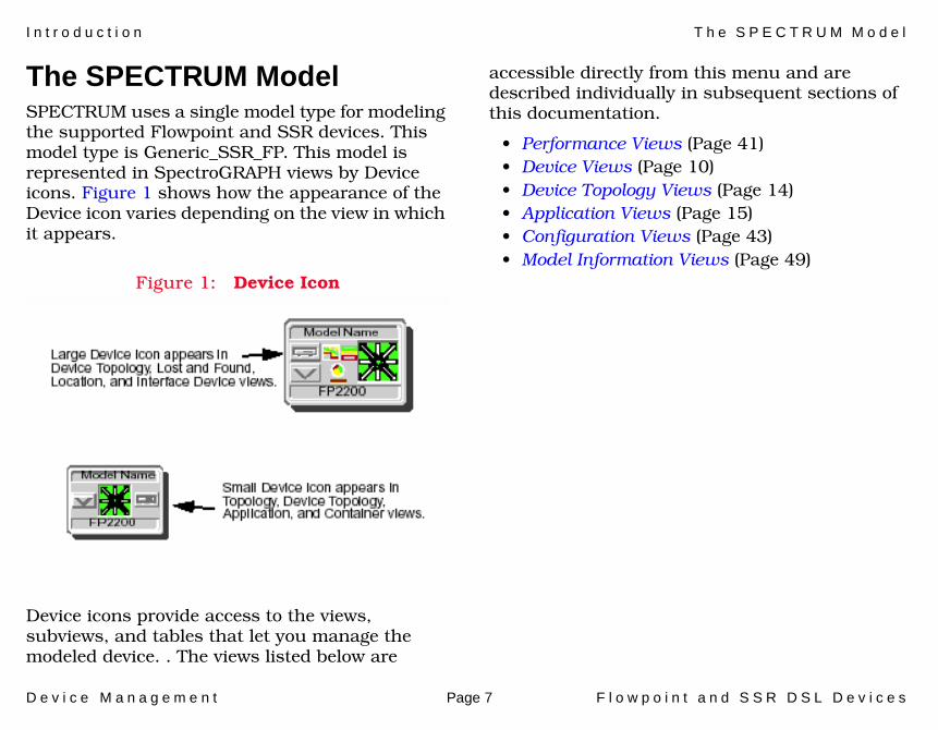
The SPECTRUM ModelSPECTRUM uses a single model type for modeling the supported Flowpoint and SSR devices. This model type is Generic_SSR_FP. This model is represented in SpectroGRAPH views by Device icons. Figure 1 shows how the appearance of the Device icon varies depending on the view in which it appears.
Figure 1: Device Icon
Device icons provide access to the views, subviews, and tables that let you manage the modeled device. . The views listed below are
accessible directly from this menu and are described individually in subsequent sections of this documentation.
• Performance Views (Page 41)• Device Views (Page 10)• Device Topology Views (Page 14)• Application Views (Page 15)• Configuration Views (Page 43)• Model Information Views (Page 49)
D e v i c e M a n a g e m e n t Page 8 F l o w p o i n t a n d S S R D S L D e v i c e s
Tasks
This section identifies various management and troubleshooting tasks that can be performed for models of the Flowpoint and SSR devices using the views, icons, and labels referenced within this document.
Application Information (examine)• Application Views (Page 15)
Device (configure)• Configuration Views (Page 43)
Device Performance (monitor)• Device Views (Page 10)
• Device Performance View (Page 42)
DHCP Client Lease Information (configure)• DHCP Server Client View (Page 28)
DOD Information (configure/examine)• DOD Operation/Bridging View (Page 31)
• DOD Configuration View (Page 44)
File Transfer (initiate/examine)• Download/Upload Information View (Page 17)
Interface Mask and Address (examine)• Secondary Address Panel (Page 13)
LAN Information (configure)• Ethernet Information View (Page 20)
Model Information (examine)• Model Information Views (Page 49)
Network Address Translation (configure)• Ethernet NAT Information View (Page 22)
Port Configuration (examine/modify)• Interface Device View (Page 10)
• Interface Icon (Page 11)
• Device Configuration View (Page 43)
A Port (examine/enable/disable)• Interface Status View (Page 12)
T a s k s T h e S P E C T R U M M o d e l
D e v i c e M a n a g e m e n t Page 9 F l o w p o i n t a n d S S R D S L D e v i c e s
Port Statistics (monitor) • Port Performance View (Page 42)
System Information (configure)• System Information View (Page 23)
WAN Information (examine)• WAN Information View (Page 30)

D e v i c e M a n a g e m e n t Page 10 F l o w p o i n t a n d S S R D S L D e v i c e s
Device Views
This section describes the Device views and subviews available for models of Flowpoint and SSR devices.
This view (Figure 2) uses icons and labels to represent the device and its components, such as modules, ports, and applications. The view provides dynamic configuration and performance information for each of the device’s serial and network I/O ports, which are represented by Interface icons in the bottom panel of the view.
• Interface Device View• Interface Status View (Page 12)• Secondary Address Panel (Page 13)
Interface Device ViewThis view provides dynamic configuration and performance information for each of the device’s interfaces, which are represented by Interface icons in the bottom panel of the view (see Figure 2). The middle panel of the view also displays a Device icon, which allows you to monitor the device operation and access other device-specific views.
Figure 2: Interface Device View
SpectroGRAPH: Router Device: Model Name
File View HelpTools
Model NameContactDescriptionLocation
Sys Up TimeManufacturerDevice TypeSerial Number
Network Address
Interface Description
Filter Physical
Interface Options PanelDevice Icon
XYZ_Mxxx
Model Name
1Ethernet
0:0:1D:F:FD:B6
ei0
0.0.0.0
ON
5SFTWARLPBK
0:0:1D:F:FD:B6
lo0
0.0.0.0
ON
9ATM8023
0:0:1D:F:FD:B6
zn1
0.0.0.0
ON
512AAL5
UAAL5
0.0.0.0
ON
2ATMCPU
0.0.0.0
ON
6ATM portCPU.1
0.0.0.0
ON
ATM7A1
0.0.0.0
ON
ATM7B1
0.0.0.0
ON
ATM7B2
0.0.0.0
ON
ATM7B3
0.0.0.0
ON
ATM8B1
0.0.0.0
ON
ATM8B2
0.0.0.0
ON
ATM8B3
0.0.0.0
ON
ATM8B4
0.0.0.0
ON
10
2783905 2783909
11
7
3 4
8
Interface Icons
Bookmarks
Model Name of type XYZ_Mxxx of Landscape node: Primary
Primary Application Gen Bridge App

D e v i c e V i e w s I n t e r f a c e D e v i c e V i e w
D e v i c e M a n a g e m e n t Page 11 F l o w p o i n t a n d S S R D S L D e v i c e s
Interface IconFigure 3 shows a close-up of a Flowpoint Interface icon from an Interface Device view. Most of the informational labels on the icon also provide double-click access to other views, as explained in the following label descriptions.
Figure 3: Interface Icon
Iterface Number LabelThis label displays the interface (port) number.
IF Status LabelThis label displays the current status of the interface for the primary application selected, e.g., Gen Rtr App or MIB-II App. Table 1 lists the possible label color representations. Note that the color of the label also depends on the interface’s current Administrative Status, which you set in the Interface Status View (Page 12). This view can be accessed by double-clicking the label.
Interface Type LabelThis label identifies the interface type (Ethernet, ATM, etc.). Double-click this label to access the Interface Configuration View (Page 44).
c
f
b
1ethernet
0:0:1D:F:FD:B6
a
a Iterface Number Label
b IF Status Label
c Interface Type Label
d Network Type Label
e Physical Address Label
f IP Address Label
fxp0
0.0.0.0
d
e
ON Table 1: Interface Status Label Colors
Color OperationalStatus
AdministrativeStatus
LabelText
Green up up ON
Blue down down OFF
Yellow down up OFF
Red testing testing TEST
D e v i c e V i e w s I n t e r f a c e S t a t u s V i e w
D e v i c e M a n a g e m e n t Page 12 F l o w p o i n t a n d S S R D S L D e v i c e s
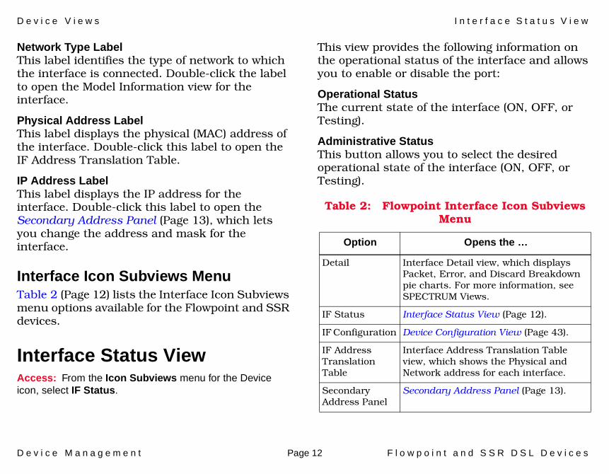
Network Type LabelThis label identifies the type of network to which the interface is connected. Double-click the label to open the Model Information view for the interface.
Physical Address LabelThis label displays the physical (MAC) address of the interface. Double-click this label to open the IF Address Translation Table.
IP Address LabelThis label displays the IP address for the interface. Double-click this label to open the Secondary Address Panel (Page 13), which lets you change the address and mask for the interface.
Interface Icon Subviews MenuTable 2 (Page 12) lists the Interface Icon Subviews menu options available for the Flowpoint and SSR devices.
Interface Status ViewAccess: From the Icon Subviews menu for the Device icon, select IF Status.
This view provides the following information on the operational status of the interface and allows you to enable or disable the port:
Operational StatusThe current state of the interface (ON, OFF, or Testing).
Administrative StatusThis button allows you to select the desired operational state of the interface (ON, OFF, or Testing).
Table 2: Flowpoint Interface Icon Subviews Menu
Option Opens the …
Detail Interface Detail view, which displays Packet, Error, and Discard Breakdown pie charts. For more information, see SPECTRUM Views.
IF Status Interface Status View (Page 12).
IF Configuration Device Configuration View (Page 43).
IF Address Translation Table
Interface Address Translation Table view, which shows the Physical and Network address for each interface.
Secondary Address Panel
Secondary Address Panel (Page 13).
D e v i c e V i e w s S e c o n d a r y A d d r e s s P a n e l
D e v i c e M a n a g e m e n t Page 13 F l o w p o i n t a n d S S R D S L D e v i c e s
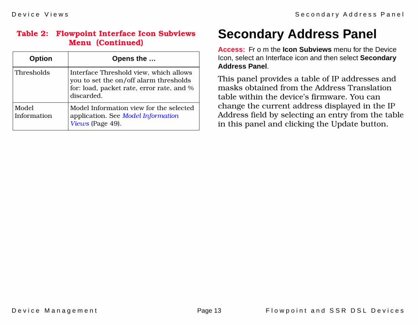
Secondary Address PanelAccess: Fr o m the Icon Subviews menu for the Device Icon, select an Interface icon and then select Secondary Address Panel.
This panel provides a table of IP addresses and masks obtained from the Address Translation table within the device’s firmware. You can change the current address displayed in the IP Address field by selecting an entry from the table in this panel and clicking the Update button.
Thresholds Interface Threshold view, which allows you to set the on/off alarm thresholds for: load, packet rate, error rate, and % discarded.
Model Information
Model Information view for the selected application. See Model Information Views (Page 49).
Table 2: Flowpoint Interface Icon Subviews Menu (Continued)
Option Opens the …

D e v i c e M a n a g e m e n t Page 14 F l o w p o i n t a n d S S R D S L D e v i c e s
Device Topology Views
This section provides brief descriptions of the Device Topology views available for models of Flowpoint and SSR devices.
Access: From the Icon Subviews menu for the Device icon, select Device Topology.
The Device Topology view (Figure 4) shows the connections between a modeled device and other network entities. The lower panel of the view uses Interface icons to represent the device’s serial, network, and I/O ports. These icons provide the same information and menu options as those in the Device Views (Page 10). If a device is connected to a particular interface, a Device icon appears on the vertical bar above the Interface icon along with an icon representing the network group that contains the device.
Refer to the SPECTRUM Views documentation for details on Device Topology view.
Figure 4: Device Topology View
File View HelpTools
1Ethernet
0:0:1D:F:FD:B6ei0
0.0.0.0
ON 2ATM
0:0:1D:F:FD:B6A2
0.0.0.0
ON 3ATM
0:0:1D:F:FD:B6CPU
0.0.0.0
ON
XYZ_Mxxx
Model Name
Bookmarks
SpectroGRAPH: Device Topology: Model Name
Graphic of<manufacturer>
Device
Model Name of type Model Type of Landscape node: Primary

D e v i c e M a n a g e m e n t Page 15 F l o w p o i n t a n d S S R D S L D e v i c e s
Application Views
This section describes the main Application view and the associated application-specific subviews available for models of Flowpoint and SSR devices.
Access: From the Icon Subviews menu for the Device icon, select Application.
Main Application ViewWhen a device model is created, SPECTRUM automatically creates models for each of the major and minor applications supported by the device. The main Application view identifies all of these application models, shows their current condition status, and provides access to application-specific subviews. Figure 5 shows this view in the Icon mode. If you prefer the List mode, which displays applications as text labels, select View > Mode > List.
For more information on this view, refer to the MIBs and the Application View documentation.
Figure 5: Flowpoint Application View
SpectroGRAPH: Application: Model Name
Model Name
Contact
Description
Location
Network Address System Up Time
Manufacturer
Device Type
Serial Number
Model Name
6E132_25
Model Name
Model Type
File View Tools Bookmarks
Model Name of type <model type> of Landscape node: Primary
Help

A p p l i c a t i o n V i e w s M a i n A p p l i c a t i o n V i e w
D e v i c e M a n a g e m e n t Page 16 F l o w p o i n t a n d S S R D S L D e v i c e s
Common ApplicationsFor the most part, these applications represent the non proprietary MIBs supported by your device. Listed below (beneath the title of the SPECTRUM document that describes them) are some of the common applications currently supported by SPECTRUM.
• Routing Applications- Generic Routing- Repeater- AppleTalk- DECnet- OSPF- OSPF2- BGP4- VRRP
• Bridging Applications- Ethernet Special Database- Spanning Tree- Static- Transparent
- PPP Bridging- Source Routing- Translation- QBridge
• MIB II Applications- SNMP- IP- ICMP- TCP- System2- UDP
• Transmission Applications- FDDI- Point to Point- DS1- DS3- RS-232- WAN- Frame Relay- Token Ring- Ethernet- Fast Ethernet- rfc1317App- rfc1285App- rfc1315App- 802.11App- SONET
Note:Note:
The documents listed below (in bold font) are available for viewing at:
www.aprisma.com/manuals/

A p p l i c a t i o n V i e w s S u p p o r t e d A p p l i c a t i o n s
D e v i c e M a n a g e m e n t Page 17 F l o w p o i n t a n d S S R D S L D e v i c e s
• Technology Applications- APPN- ATM Client- DHCP- PNNI- rfc1316App- DLSw
Supported ApplicationsThis device has the followind Device-Specific Applciations;
• SSR Download Application (Page 17)• SSRetherApp (Page 20)• SSRsystemApp (Page 23)• SSRwanApp (Page 29)
SSR Download ApplicationThis major application (model type SSRdownloadApp) provides the following application-specific subview:
• Download/Upload Information View (see below)
Download/Upload Information ViewAccess: From the Icon Subviews menu for the SSRdownloadApp Application icon, select Download/Upload Information.
This view contains the following information:
DL Force On BootWhen set to “1”, the system will request a download during the next system restart.
DL Initiate Cold BootWhen set to “1”, the “boot” software initiates a system reboot.
DL TFTP Request HostThe IP Address of the server used when a network “boot” is requested.
Note:Note:
Aprisma Management Technologies can provide training, technical assistance, and custom engineering support services for creating application models and their associated views.

A p p l i c a t i o n V i e w s S S R D o w n l o a d A p p l i c a t i o n
D e v i c e M a n a g e m e n t Page 18 F l o w p o i n t a n d S S R D S L D e v i c e s
DL TFTP RequestThe filename requested of the server when a network “boot” is requested.
DL Last Image FilenameFilename of the last image successfully loaded into memory.
DL Last Server IP AddressIP Address of the server used to load the present image into flash memory.
TFTP Server Gtway IP AddressThe IP address of the gateway/router that connects this SNMP agent to the TFTP server.
DL Oper StatusThe current status of any upload or download operations. The possible values are listed in Table 3 (Page 18).
DL OnLine DownloadThe value of this field controls an “upload” or “download.” Possible values are listed in Table 4 (Page 19).
Table 3: DL Operational Status Value
Value Description
normalOperation
Download started and finished normally.
downloadActive Download in progress.
download CompleteError
Download was started but an error was detected.
upLoadActive Upload in progress.
upLoadCompleteError
Upload started but an error was detected.
removeActive A local file is being removed.
removeCompleteError
Failed to remove a local file.
unknown Unknown.
other None of the above.
A p p l i c a t i o n V i e w s S S R D o w n l o a d A p p l i c a t i o n
D e v i c e M a n a g e m e n t Page 19 F l o w p o i n t a n d S S R D S L D e v i c e s
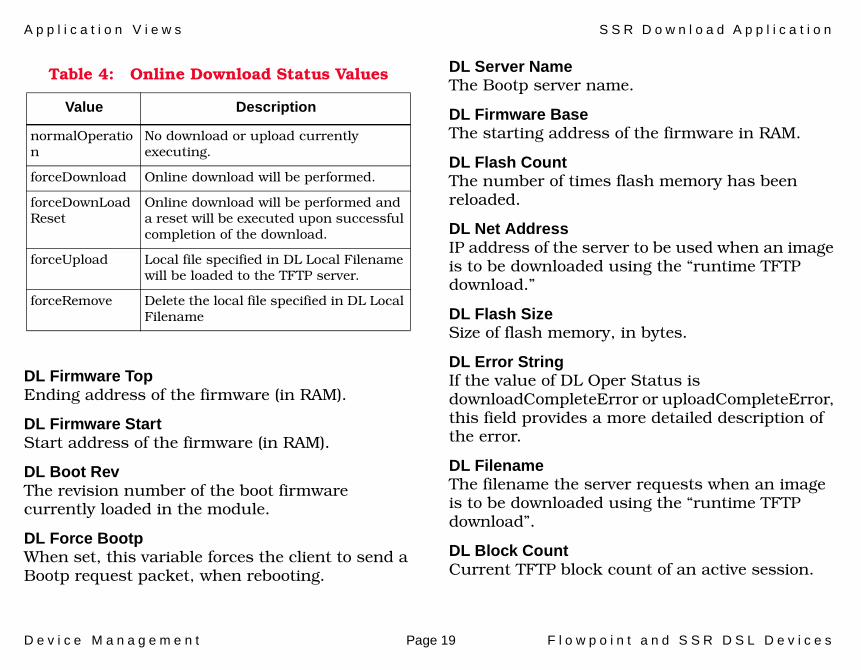
DL Firmware TopEnding address of the firmware (in RAM).
DL Firmware StartStart address of the firmware (in RAM).
DL Boot RevThe revision number of the boot firmware currently loaded in the module.
DL Force BootpWhen set, this variable forces the client to send a Bootp request packet, when rebooting.
DL Server NameThe Bootp server name.
DL Firmware BaseThe starting address of the firmware in RAM.
DL Flash CountThe number of times flash memory has been reloaded.
DL Net AddressIP address of the server to be used when an image is to be downloaded using the “runtime TFTP download.”
DL Flash SizeSize of flash memory, in bytes.
DL Error StringIf the value of DL Oper Status is downloadCompleteError or uploadCompleteError, this field provides a more detailed description of the error.
DL FilenameThe filename the server requests when an image is to be downloaded using the “runtime TFTP download”.
DL Block CountCurrent TFTP block count of an active session.
Table 4: Online Download Status Values
Value Description
normalOperation
No download or upload currently executing.
forceDownload Online download will be performed.
forceDownLoad Reset
Online download will be performed and a reset will be executed upon successful completion of the download.
forceUpload Local file specified in DL Local Filename will be loaded to the TFTP server.
forceRemove Delete the local file specified in DL Local Filename
A p p l i c a t i o n V i e w s S S R e t h e r A p p
D e v i c e M a n a g e m e n t Page 20 F l o w p o i n t a n d S S R D S L D e v i c e s
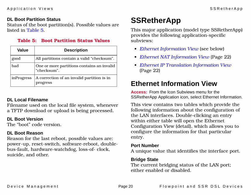
DL Boot Partition StatusStatus of the boot partition(s). Possible values are listed in Table 5.
DL Local FilenameFilename used on the local file system, whenever a TFTP download or upload is being processed.
DL Boot VersionThe “boot” code version.
DL Boot ReasonReason for the last reboot, possible values are: power-up, reset-switch, software-reboot, double-bus-fault, hardware-watchdog, loss-of- clock, suicide, and other.
SSRetherAppThis major application (model type SSRetherApp) provides the following application-specific subviews:
• Ethernet Information View (see below)
• Ethernet NAT Information View (Page 22)
• Ethernet IP Translation Information View (Page 22)
Ethernet Information ViewAccess: From the Icon Subviews menu for the SSRetherApp Application icon, select Ethernet Information.
This view contains two tables which provide the following information about the configuration of the LAN interfaces. Double-clicking an entry within either table will open the Ethernet Configuration View (detail), which allows you to configure the information for that particular entry.
Port NumberA unique value that identifies the interface port.
Bridge StateThe current bridging status of the LAN port; either enabled or disabled.
Table 5: Boot Partition Status Values
Value Description
good All partitions contain a valid “checksum”.
bad One or more partitions contains an invalid “checksum”.
inProgress A correction of an invalid partition is in progress
A p p l i c a t i o n V i e w s S S R e t h e r A p p
D e v i c e M a n a g e m e n t Page 21 F l o w p o i n t a n d S S R D S L D e v i c e s
IP StateDetermines whether the IP protocol is routed via this LAN interface.
IPX StateDetermines whether the IPX protocol is routed via this LAN interface.
IP Net AddressAllows you to set or retrieve the IP address for this LAN interface.
IP Net MaskAllows you to set or retrieve the IP network mask for this LAN interface.
IPX Net AddressAllows you to set or retrieve the IPX external network number for this LAN interface.
Ipx Frame TypeAllows you to set or retrieve the IPX frame type, generated by the router, for this interface.
Ether IP Opt Recv RIPAllows the processing of IP RIP 1 and RIP 2 packets received from this LAN interface.
Ether IP Opt Send RIPAllows sending IP RIP 1 compatible packets to the LAN interface when IP routing is enabled.
Ether IP Opt Recv RIP DefaultWhen routing is enabled, this allows you to update the IP routing table with the default route received on this LAN interface.
Ether IP Opt Send RIP DefaultWhen IP routing is enabled, this allows the system to advertise itself as the default router on this LAN interface.
IPX Str Next AddressAllows you to set or retrieve the IPX external network number for this LAN interface.
IP Default GatewayAllows you to set or retrieve the IP address for the default gateway and assign it to the interface specified in Port Number.
Ether IP Opt Recv RIP1Allows the processing of IP RIP 1 packets received from this LAN interface.
Ether IP Opt Send RIP1Allows sending IP RIP 1 packets to this LAN interface when IP routing is enabled.
Ether IP Opt Recv RIP2Allows the processing of IP RIP 2 packets received from this LAN interface.
Ether IP Opt Send RIP2Allows sending IP RIP 2 packets to this LAN
A p p l i c a t i o n V i e w s S S R e t h e r A p p
D e v i c e M a n a g e m e n t Page 22 F l o w p o i n t a n d S S R D S L D e v i c e s
interface when IP routing is enabled.
IP RIP Multicast AddressAllows you to set or retrieve the RIP 2 Multicast address for this LAN interface.
NAT StateIf IP protocol is routed through this interface, this value determines whether IP address/port translation is performed via this LAN interface.
Ethernet NAT Information ViewAccess: Fr o m the Icon Subviews menu for the SSRetherApp Application icon, select Ethernet NAT Information.
This view contains the Ethernet Network Address Translation (NAT) Host Mapping table which provides the following information:
First Private IP AddressThe first private IP address that begins the range of private IP addresses mapped to public IP addresses.
Last Private IP AddressThe last private IP address that ends the range of private IP addresses mapped to public IP addresses.
First Public AddressThe first public IP address that begins the range of public IP addresses mapped to private IP addresses.
NAT Host Mapping StatusThe value of this field determines whether an object in this table will be created, modified or deleted.
Ethernet IP Translation Information ViewAccess: From t he Icon Subviews menu for the SSRetherApp Application icon, select Ethernet IP Translation.
This view contains the ethernet server IP Translation Server Table which contains the following information about server selection when doing IP address translation:
IP First Private PortFirst private port, in range, used by the server.
IP First Translation PortFirst public port, in range, used by this server.
IP Last Translation PortLast public port, in range, used by this server.

A p p l i c a t i o n V i e w s S S R s y s t e m A p p
D e v i c e M a n a g e m e n t Page 23 F l o w p o i n t a n d S S R D S L D e v i c e s
IP Translation ProtocolThe protocol used by this server.
IP Translation Server IP AddressThe IP address of the server used when doing IP address translation.
IP Translation StatusThe value of this field determines whether an object in this table will be created, modified or deleted.
SSRsystemAppThis major application (SSRsystemApp) has two minor applications: the Dynamic Host Configuration Protocol application (model type dhcpApp) and the Directory application (model type dirApp). The Icon Subviews menus for these applications provide access to the following application-specific subviews:
• System Information View (Page 23)• CallerID/UDP Relay Information View
(Page 26)• DHCP Server Option View (Page 26)• DHCP Server Global Option View (Page 27)• DHCP Server Subnet View (Page 27)• DHCP Server Subnet Option View (Page 28)• DHCP Server Client View (Page 28)
• DHCP Server Client Option View (Page 29)• Directory Information View (Page 29)
System Information ViewAccess: Fr o m the Icon Subviews menu for the SSRsystemApp Application icon, select System Information.
This view provides the following information about the Flowpoint system group:
Sys NameAn administratively-assigned name for this managed node. It will be the same name as the one defined in MIB2.
Sys MessageAn administratively-assigned message for this managed node.
Sys PasswordAn administratively-assigned password for this managed node. The password will be used in the authentication phase of (point-to-point-protocols) PPP.
Sys AuthenAn administratively-assigned authentication override type for this managed node.

A p p l i c a t i o n V i e w s S S R s y s t e m A p p
D e v i c e M a n a g e m e n t Page 24 F l o w p o i n t a n d S S R D S L D e v i c e s
Sys OperationSave or load the system configuration (only what is defined in this group) to/from FLASH memory, or perform other control operations such as reboot. Possible values are listed in Table 6.
Sys Software VersionThe software version run by the system.
Sys Last Log EventThe last system event reported to the console.
Login PasswordAssign or change the administrator’s password for login.
Write TimeoutSets and retrieves a timeout value (in minutes) during which a user logged in can modify objects.
Default -- 10 minutes (until changed).
No security timeout -- set to 0.
Write TimerThis object retrieves the current security timer value. It returns how many minutes are left (if any) before a new login must be performed.
Default Single UserNetwork Address Translation (NAT) has rendered this object obsolete. For backwards compatibility purposes, this object still allows you to set the IP address of the client for which IP address translation is to be performed.
Internet FirewallEnables or disable the internet firewall filter. The filter discards any IP packet arriving from the WAN with a source IP address belonging to the LAN.
IPX SupportedIndicates whether IPX is supported in the router software.
MIB CompatibilityIndicates that this private MIB is fully compatible with RFC 1155.
Table 6: System Operation Values
Value Description
save Save to Flash.
load Load to Flash (not recommended).
erase Erase configuration in Flash.
reboot Reboot after syncing file system.
set-clock Set the RTC with fpSysXXX values.
reboot-likefactory
Erase config files and reboot.
reboot-like-new Erase config/autoexec files and reboot.

A p p l i c a t i o n V i e w s S S R s y s t e m A p p
D e v i c e M a n a g e m e n t Page 25 F l o w p o i n t a n d S S R D S L D e v i c e s
POTS InstalledIndicates whether Plain Old Telephone Service (POTS) hardware is installed and is software supported.
Sys Hardware VersionThe system model number, revision and serial number.
Sys Single UserThis IP address is used to define the single address to which IP translation is to occur.
Bootp RelayAllows you to get or set the IP address of the DHCP/Bootp Server when this router is acting as a Bootp relay agent.
Community NameSets and gets the SNMP community name. The default value is public.
WAN to WAN ForwardingEnables or disables the forwarding of data traffic from one WAN link to another.
Kernel RevisionThe number of times the source code has changed
Sys YearSets the year for the real-time clock.
Sys MonthSets the month for the real-time clock
Sys DaySets the day for the real-time clock.
Sys HourSets the hour for the real-time clock.
Sys MinuteSets the minute for the real-time clock.
Sys SecondSets the second for the real-time clock.
Telnet PortThe TCP port used for reception of Telnet connections to the router. Setting this value to zero disables Telnetting to the router.
SNMP PortThe TCP port used for reception of SNMP requests to the router. Setting this value to zero disables SNMP management of the router.
Sys LogoutWriting to this object prevents any change from an SNMP manager (until logged in again).
A p p l i c a t i o n V i e w s S S R s y s t e m A p p
D e v i c e M a n a g e m e n t Page 26 F l o w p o i n t a n d S S R D S L D e v i c e s
CallerID/UDP Relay Information ViewAccess: From the Icon Subviews menu for the SSRsystemApp Application icon, select CallerID/UDP Information.
This view contains the following information:
UDP Relay First PortFirst UDP port in range of UDP ports which will be relayed.
UDP Relay IP AddressIP address to receive UDP broadcast traffic.
UDP Relay Last PortLast UDP port in range of UDP ports which will be relayed.
UDP Relay StatusThe value of this field determines whether an object in this table will be created, modified or deleted.
Caller ID EnabledEnables or disables directed broadcasts to a directly connected interface.
One WAN ConnectionEnables or disables running more than one WAN link at a time to different destinations.
Sys HTTP PortThe TCP port designated to receive HTTP requests to the router.
DHCP Server Option ViewAccess: From the Icon Subviews menu for the dhcpApp Application icon, select DHCP Server Option.
This view contains the following information:
Option CodeDynamic Host Configuration protocol (DHCP) defined Option Code.
Min CountMinimum allowed number of values for this option.
Max CountMaximum allowed number of values for this option.
Option TypeValues for this option are of this type.
Option Code StatusThis value determines whether an object in this table will be created, modified or deleted.
A p p l i c a t i o n V i e w s S S R s y s t e m A p p
D e v i c e M a n a g e m e n t Page 27 F l o w p o i n t a n d S S R D S L D e v i c e s
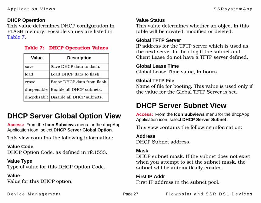
DHCP OperationThis value determines DHCP configuration in FLASH memory. Possible values are listed in Table 7.
DHCP Server Global Option ViewAccess: From the Icon Subviews menu for the dhcpApp Application icon, select DHCP Server Global Option.
This view contains the following information:
Value CodeDHCP Option Code, as defined in rfc1533.
Value TypeType of value for this DHCP Option Code.
ValueValue for this DHCP option.
Value StatusThis value determines whether an object in this table will be created, modified or deleted.
Global TFTP ServerIP address for the TFTP server which is used as the next server for booting if the subnet and Client Lease do not have a TFTP server defined.
Global Lease TimeGlobal Lease Time value, in hours.
Global TFTP FileName of file for booting. This value is used only if the value for the Global TFTP Server is set.
DHCP Server Subnet ViewAccess: From the Icon Subviews menu for the dhcpApp Application icon, select DHCP Server Subnet.
This view contains the following information:
AddressDHCP Subnet address.
MaskDHCP subnet mask. If the subnet does not exist when you attempt to set the subnet mask, the subnet will be automatically created.
First IP AddrFirst IP address in the subnet pool.
Table 7: DHCP Operation Values
Value Description
save Save DHCP data to flash.
load Load DHCP data to flash.
erase Erase DHCP data from flash.
dhcpenable Enable all DHCP subnets.
dhcpdisable Disable all DHCP subnets.
A p p l i c a t i o n V i e w s S S R s y s t e m A p p
D e v i c e M a n a g e m e n t Page 28 F l o w p o i n t a n d S S R D S L D e v i c e s
Last IP AddrLast IP address in the subnet pool.
TFTP ServerIP address for the TFTP server. This subnet value is used as the next server for booting if the Client Lease does not have a TFTP server defined.
TFTP FileName of file for booting. This value is used only if the subnet value for the TFTP server is set.
BootpAllow or disallow servicing of Bootp requests for this Subnet.
Lease TimeSubnet default lease time value, in hours.
StatusThis value determines whether an object in this table will be created, modified or deleted.
Conflict ActionsThe action this DHCP server should take if this subnet is for the local LAN and another DHCP server for the local LAN exists.
DHCP Server Subnet Option ViewAccess: From the Icon Subviews menu for the dhcpApp Application icon, select DHCP Server Subnet Option.
This view contains the following information:
Value CodeDHCP Option Code as defined in rfc1533.
Value TypeType of value for this DHCP Option Code.
ValueValue for this DHCP Option.
Value StatusThis value determines whether an object in this table will be created, modified or deleted.
DHCP Server Client ViewAccess: From the Icon Subviews menu for the dhcpApp Application icon, select DHCP Server Client.
The information in this table is used to set or clear DHCP Client Lease information. It contains the following information:
AddressDHCP Client Lease address.
TFTP ServerIP address for the TFTP server.
TFTP FileName of file for booting.

A p p l i c a t i o n V i e w s S S R w a n A p p
D e v i c e M a n a g e m e n t Page 29 F l o w p o i n t a n d S S R D S L D e v i c e s
BootpAllow or disallow servicing of Bootp requests for this Subnet. Default is disallow.
Lease TimeClient default lease time value in hours.
Expire Time YearThe year of the Client Lease expire time.
Expire Time MonthThe month of the Client Lease expire time.
Expire Time DayThe day of the Client Lease expire time.
Expire Time HourThe hour of the Client Lease expire time.
Expire Time MinuteThe minute of the Client Lease expire time.
Expire Time SecondThe seconds of the Client Lease expire time.
StatusThis value determines whether an object in this table will be created, modified or deleted.
DHCP Server Client Option ViewAccess: From the Icon Subviews menu for the dhcpApp Application icon, select DHCP Server Client Option.
This view is exactly the same as the DHCP Server Subnet Option View (Page 28)
Directory Information ViewAccess: From the Icon Subviews menu for the dirApp Application icon, select Directory Information.
This view contains the following information:
Directory IndexA unique value identifying a file to be read.
Directory NameA description of the file.
Directory SizeThe size of the file, in bytes.
SSRwanAppThis major application (model type SSRwanApp has five minor applications: the Dial on Demand Application (model type dodApp), the Plain Old Telephone System Application (model potsApp), the loginApp, the ipApp, and the isdnApp. The Icon Subviews menus associated with these applications provide access to the following application-specific subviews:
• WAN Information View (Page 30)
A p p l i c a t i o n V i e w s S S R w a n A p p
D e v i c e M a n a g e m e n t Page 30 F l o w p o i n t a n d S S R D S L D e v i c e s
• DOD Operation/Bridging View (Page 31)
• Remote IP Network Information View (Page 31)
• Phone/Call ID Information View (Page 31)
• Remote MAC View (Page 32)
• Remote IPX Network Table View (Page 32)
• Remote IPX SAP Table View (Page 33)
• IP Filter Table View (Page 33)
• IPX Filter Table View (Page 34)
• Callers Table View (Page 34)
• Server IP Translation Table View (Page 34)
• DOD NAT Host Mapping Table View (Page 34)
• POTS Information View (Page 35)
• POTS Interface Information View (Page 36)
• IP Information View (Page 37)
• Login Information View (Page 37)
• ISDN Information View (Page 38)
WAN Information ViewAccess: From the Icon Subviews menu for the SSRwanApp Application icon, select WAN Information.
This view contains the following information:
WAN IndexThe interface index number.
WAN Instant Out UtilInstantaneous output bandwidth utilization.
WAN Instant In UtilInstantaneous input bandwidth utilization.
WAN Avg Out UtilSliding average of output bandwidth utilization
WAN Avg In Util
Sliding average of input bandwidth utilization.WAN Remote Name
Name of the user/destination to which this interface is currently connected.
WAN Remote TimeThe number of seconds that this interface has
been connected.
WAN If IndexThe corresponding MIB-II “ifindex” for this
interface.
WAN Out SpeedThis interface’s current transmit bandwidth speed, in bits per second.

A p p l i c a t i o n V i e w s S S R w a n A p p
D e v i c e M a n a g e m e n t Page 31 F l o w p o i n t a n d S S R D S L D e v i c e s
WAN In SpeedThis interface’s current receive bandwidth speed, in bits per second.
DOD Operation/Bridging ViewAccess: From the Icon Subviews menu for the dodApp Application icon, select DOD Configuration.
This view contains the following information:
DOD OperationSpecifies whether to save, load, or erase Dial On Demand (DOD) configuration in FLASH memory.
Remote MAC DefaultRemote destination name of the default bridge.
Remote IP Network Information ViewAccess: From the Icon Subviews menu for the dodApp Application icon, select Remote Ip Information.
This view contains the following information:
IP Net AddressThe IP network address of an entry of the static IP routing table.
IP Net GatewayThe IP address of the gateway to which packets are sent when the static route is over a broadcast medium.
IP Net HopsThe hop count for the specified IP network address and destination name.
IP Net MaskThe IP network mask of an entry of the static IP
routing table.
IP Net OperationAdds or removes a static IP route to/from the destination.
Phone/Call ID Information ViewAccess: From the Icon Subviews menu for the dodApp Application icon, select Phone Information.
This view contains the Phone Information Table and the Call ID Table which provide the following information:
A p p l i c a t i o n V i e w s S S R w a n A p p
D e v i c e M a n a g e m e n t Page 32 F l o w p o i n t a n d S S R D S L D e v i c e s
Phone Information TablePhone IndexA unique value identifying the phone number in the table containing the specified Call ID Type and Destination Name.
Phone NumberThe phone number.
Phone SpeedThe line speed (in bits per seconds) for asynchronous connections.
Call ID TableCall ID PhonesNumber of entries in the Phone Information Table for this type of connection and this remote.
Call ID TypeThe connection type
Remote MAC ViewFrom the Icon Subviews menu for the dodApp Application icon, select Remote MAC Information.
This view contains the following information:
Remote MAC AddressContains the IEEE unique MAC address of statically configured devices for bridging purposes.
Remote MAC OperationAdds or removes a static address of a bridged destination or a destination to be bridged.
Remote IPX Network Table ViewAccess: From the Icon Subviews menu for the dodApp Application icon, select Remote IPX N/W Information.
This view contains the following information:
IPX Net AddressThe IPX network address of an entry in the static IPX routing table.
IPX Net MetricThe number of hops to reach this IPX network (via this destination).
IPX Net OperationAdds or removes a static IPX route to/from this destination.
IPX Net Str AddressThe IPX network address of an entry in the static IPX routing table.

A p p l i c a t i o n V i e w s S S R w a n A p p
D e v i c e M a n a g e m e n t Page 33 F l o w p o i n t a n d S S R D S L D e v i c e s
IPX Net TicksNumber of ticks (measured in intervals of 1/18th of a second) necessary to reach this IPX network number (via this destination).
Remote IPX SAP Table ViewAccess: From the Icon Subviews menu for the dodApp Application icon, select Remote IPX SAP Information.
This view contains the following information:
IPX SAP NameThe name by which this IPX service is known.
IPX SAP Net AddressThe internal IPX network number of the server providing this particular IPX service.
IPX SAP Node AddressThe node address on the IPX network number from which a server provides this particular IPX service.
IPX SAP SocketThe socket (i.e. internal port number) of the server at which the specified IPX service is provided.
IPX SAP TypeThe type of service (i.e. File Service, Advertising Print Service, etc.).
IPX SAP HopsThe number of hops necessary to reach the provider of this service.
IPX SAP OperationAdds or deletes IPX SAP services to/from this destination.
IPX SAP Str Net AddressThe internal IPX network number of the server providing this particular IPX service. This value is expressed as an ASCII string and converted to
hexadecimal by the firmware.IPX SAP Str Socket
The socket (i.e. internal port number) of the server at which the specified IPX service is provided. This value is expressed as an ASCII string and converted to hexadecimal by the firmware.
IPX SAP Str TypeThe type of service (i.e. File Service, Advertising Print Service, etc.). This value is expressed as an ASCII string and converted to hexadecimal by the firmware.
IP Filter Table ViewAccess: From the Icon Subviews menu for the dodApp Application icon, select IP Filter Information.
A p p l i c a t i o n V i e w s S S R w a n A p p
D e v i c e M a n a g e m e n t Page 34 F l o w p o i n t a n d S S R D S L D e v i c e s
This table provides a set of IP filters for this remote.
IPX Filter Table ViewAccess: From the Icon Subviews menu for the dodApp Application icon, select IPX Filter Information.
This view contains the IPX Filter Table, which provides information about the IPX filters defined for this remote.
Callers Table ViewAccess: From the Icon Subviews menu for the dodApp Application icon, select Callers Information.
This view contains the following information:
Caller NumberThe number against which caller ID verification takes place or is used to find out which peer is calling, before dial-back takes place.
Caller OperationAllows you to add or remove an entry for the specified remote and connection type.
Server IP Translation Table ViewAccess: From the Icon Subviews menu for the dodApp Application icon, select Server IP Translation Server Info.
This view contains the following information:
IP Translation Ser IP AddrThe IP address of the server used for IP address translation.
IP Translation ProtocolThe protocol used by this server.
IP First Translation PortFirst public port in range, used by this server.
IP Last Translation PortLast public port in range, used by this server.
IP First Private PortThis is the first private port in range, as seen by
the server.
IP Translation StatusThis value determines whether an object in this table will be created, modified or deleted.
DOD NAT Host Mapping Table ViewAccess: From the Icon Subviews menu for the dodApp Application icon, select NAT Host Mapping Information.
This table contains the following information which is used to select Network Address
A p p l i c a t i o n V i e w s S S R w a n A p p
D e v i c e M a n a g e m e n t Page 35 F l o w p o i n t a n d S S R D S L D e v i c e s
Translation (NAT) Host Mapping when doing IP address translation.
First Private IP AddressThe first private IP address which starts the range of private IP addresses mapped to public IP addresses.
Last Private IP AddressThe last private IP address which ends the range of private IP addresses mapped to public IP addresses.
First Public IP AddressThe first public IP address which starts the range of public IP Addresses mapped to private IP addresses.
NAT Host Mapping StatusThis value determines whether an object in this table will be created, modified or deleted.
POTS Information ViewAccess: From the Icon Subviews menu for the potsApp Application icon, select POTS Information.
This is the Plain Old Telephone Service (POTS) Information view, which provides the following information:
POTS IndexIndex used to access an entry in this table: maps
to the connectors marked POTS1 and POTS2.
POTS EnabledEnable or disable the POTS functionality at the specified connector.
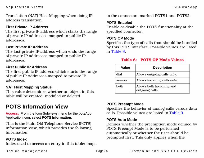
POTS OP ModeSpecifies the type of calls that should be handled by this POTS interface. Possible values are listed in Table 8.
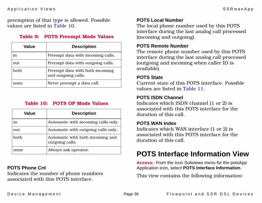
POTS Preempt ModeSpecifies the behavior of analog calls versus data calls. Possible values are listed in Table 9.
POTS Auto ModeDefines whether the preemption mode defined by POTS Preempt Mode is to be performed automatically or whether the user should be prompted first. This only applies when the
Table 8: POTS OP Mode Values
Value Description
dial Allows outgoing calls only.
answer Allows incoming calls only.
both Allows both incoming and outgoing calls.
A p p l i c a t i o n V i e w s S S R w a n A p p
D e v i c e M a n a g e m e n t Page 36 F l o w p o i n t a n d S S R D S L D e v i c e s
preemption of that type is allowed. Possible values are listed in Table 10.
POTS Phone CntIndicates the number of phone numbers associated with this POTS interface.
POTS Local NumberThe local phone number used by this POTS interface during the last analog call processed (incoming and outgoing).
POTS Remote NumberThe remote phone number used by this POTS interface during the last analog call processed (outgoing and incoming when caller ID is available).
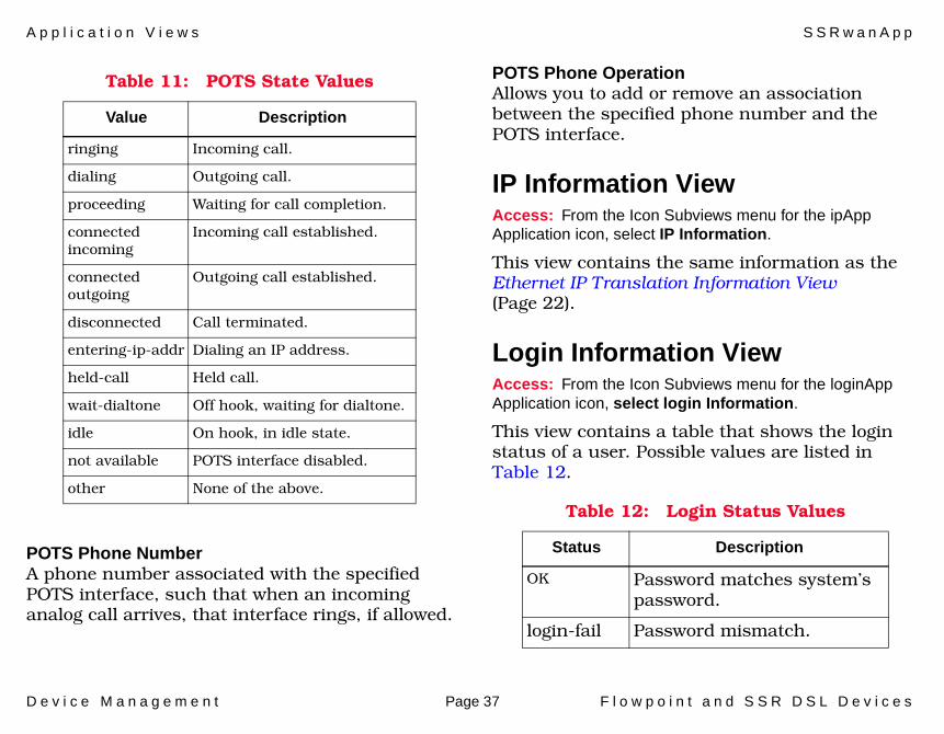
POTS StateCurrent state of this POTS interface. Possible values are listed in Table 11.
POTS ISDN ChannelIndicates which ISDN channel (1 or 2) is associated with this POTS interface for the duration of this call.
POTS WAN IndexIndicates which WAN interface (1 or 2) is associated with this POTS interface for the duration of this call.
POTS Interface Information ViewAccess: From the Icon Subviews menu for the potsApp Application icon, select POTS Interface Information.
This view contains the following information:
Table 9: POTS Preempt Mode Values
Value Description
in Preempt data with incoming calls.
out Preempt data with outgoing calls.
both Preempt data with both incoming and outgoing calls.
none Never preempt a data call.
Table 10: POTS OP Mode Values
Value Description
in Automatic with incoming calls only.
out Automatic with outgoing calls only.
both Automatic with both incoming and outgoing calls.
none Always ask operator.
A p p l i c a t i o n V i e w s S S R w a n A p p
D e v i c e M a n a g e m e n t Page 37 F l o w p o i n t a n d S S R D S L D e v i c e s
POTS Phone NumberA phone number associated with the specified POTS interface, such that when an incoming analog call arrives, that interface rings, if allowed.
POTS Phone OperationAllows you to add or remove an association between the specified phone number and the POTS interface.
IP Information ViewAccess: From the Icon Subviews menu for the ipApp Application icon, select IP Information.
This view contains the same information as the Ethernet IP Translation Information View (Page 22).
Login Information ViewAccess: From the Icon Subviews menu for the loginApp Application icon, select login Information.
This view contains a table that shows the login status of a user. Possible values are listed in Table 12.
Table 11: POTS State Values
Value Description
ringing Incoming call.
dialing Outgoing call.
proceeding Waiting for call completion.
connected incoming
Incoming call established.
connected outgoing
Outgoing call established.
disconnected Call terminated.
entering-ip-addr Dialing an IP address.
held-call Held call.
wait-dialtone Off hook, waiting for dialtone.
idle On hook, in idle state.
not available POTS interface disabled.
other None of the above.
Table 12: Login Status Values
Status Description
OK Password matches system’s password.
login-fail Password mismatch.
A p p l i c a t i o n V i e w s S S R w a n A p p
D e v i c e M a n a g e m e n t Page 38 F l o w p o i n t a n d S S R D S L D e v i c e s
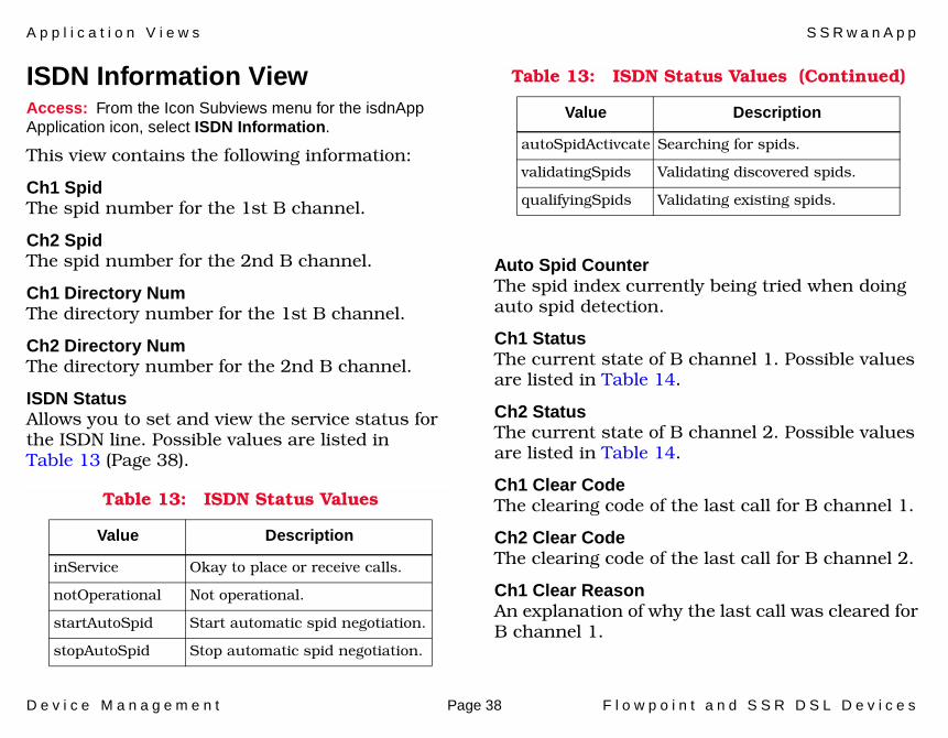
ISDN Information ViewAccess: From the Icon Subviews menu for the isdnApp Application icon, select ISDN Information.
This view contains the following information:
Ch1 SpidThe spid number for the 1st B channel.
Ch2 SpidThe spid number for the 2nd B channel.
Ch1 Directory NumThe directory number for the 1st B channel.
Ch2 Directory NumThe directory number for the 2nd B channel.
ISDN StatusAllows you to set and view the service status for the ISDN line. Possible values are listed in Table 13 (Page 38).
Auto Spid CounterThe spid index currently being tried when doing auto spid detection.
Ch1 StatusThe current state of B channel 1. Possible values are listed in Table 14.
Ch2 StatusThe current state of B channel 2. Possible values are listed in Table 14.
Ch1 Clear CodeThe clearing code of the last call for B channel 1.
Ch2 Clear CodeThe clearing code of the last call for B channel 2.
Ch1 Clear ReasonAn explanation of why the last call was cleared for B channel 1.
Table 13: ISDN Status Values
Value Description
inService Okay to place or receive calls.
notOperational Not operational.
startAutoSpid Start automatic spid negotiation.
stopAutoSpid Stop automatic spid negotiation.
autoSpidActivcate Searching for spids.
validatingSpids Validating discovered spids.
qualifyingSpids Validating existing spids.
Table 13: ISDN Status Values (Continued)
Value Description
A p p l i c a t i o n V i e w s S S R w a n A p p
D e v i c e M a n a g e m e n t Page 39 F l o w p o i n t a n d S S R D S L D e v i c e s
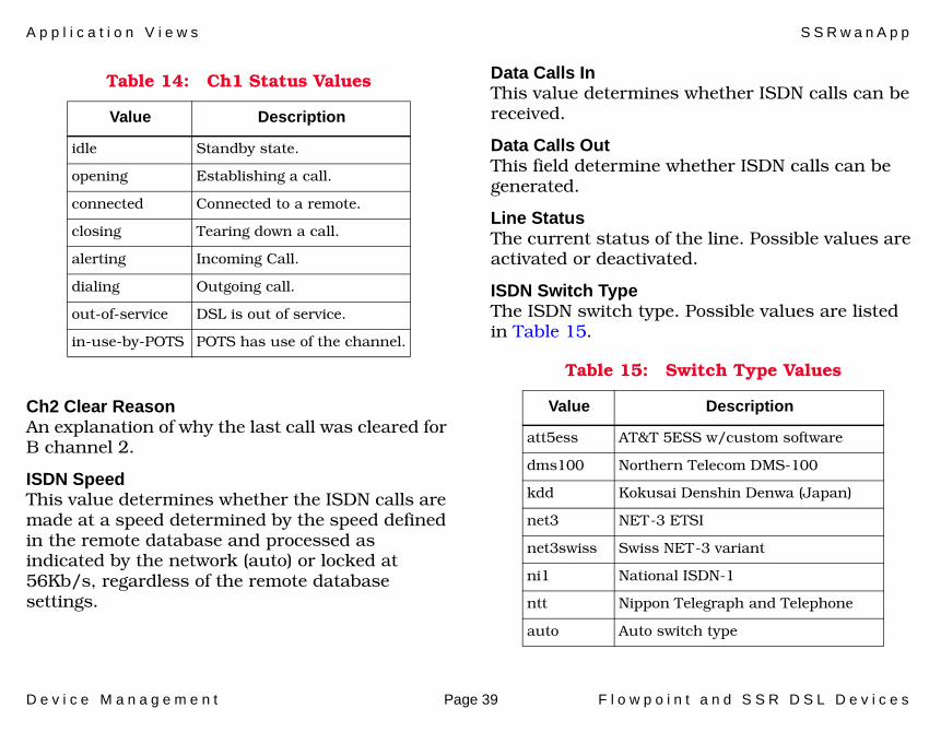
Ch2 Clear ReasonAn explanation of why the last call was cleared for B channel 2.
ISDN SpeedThis value determines whether the ISDN calls are made at a speed determined by the speed defined in the remote database and processed as indicated by the network (auto) or locked at 56Kb/s, regardless of the remote database settings.
Data Calls InThis value determines whether ISDN calls can be received.
Data Calls OutThis field determine whether ISDN calls can be generated.
Line StatusThe current status of the line. Possible values are activated or deactivated.
ISDN Switch TypeThe ISDN switch type. Possible values are listed in Table 15.
Table 14: Ch1 Status Values
Value Description
idle Standby state.
opening Establishing a call.
connected Connected to a remote.
closing Tearing down a call.
alerting Incoming Call.
dialing Outgoing call.
out-of-service DSL is out of service.
in-use-by-POTS POTS has use of the channel.
Table 15: Switch Type Values
Value Description
att5ess AT&T 5ESS w/custom software
dms100 Northern Telecom DMS-100
kdd Kokusai Denshin Denwa (Japan)
net3 NET-3 ETSI
net3swiss Swiss NET-3 variant
ni1 National ISDN-1
ntt Nippon Telegraph and Telephone
auto Auto switch type
A p p l i c a t i o n V i e w s S S R w a n A p p
D e v i c e M a n a g e m e n t Page 40 F l o w p o i n t a n d S S R D S L D e v i c e s
ISDN OperationAllows you to save, load, or erase the ISDN configuration to/from FLASH memory.
D e v i c e M a n a g e m e n t Page 41 F l o w p o i n t a n d S S R D S L D e v i c e s
Performance Views
This section provides brief descriptions of the Performance views available for the Lucent Cajun P330/550/880 devices in SPECTRUM.
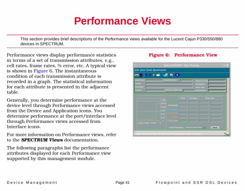
Performance views display performance statistics in terms of a set of transmission attributes, e.g., cell rates, frame rates, % error, etc. A typical view is shown in Figure 6. The instantaneous condition of each transmission attribute is recorded in a graph. The statistical information for each attribute is presented in the adjacent table.
Generally, you determine performance at the device level through Performance views accessed from the Device and Application icons. You determine performance at the port/interface level through Performance views accessed from Interface icons.
For more information on Performance views, refer to the SPECTRUM Views documentation.
The following paragraphs list the performance attributes displayed for each Performance view supported by this management module.
Figure 6: Performance View
SpectroGRAPH: Type Routing
Model Name
Contact
Description
Location
Network Address System Up Time
Manufacturer
Device Type
Serial Number
Log
100.0
10.00
1.00
0.10
0.01
000:40:0 0:30:0 0:20:0
Value Average Peak Value
* Frame Rate
% Delivered
% Forwarded
% Transmit
% Error
DetailGraph Properties Scroll to Date-Time
File View Tools Bookmarks
% Discarded*Frames per second
type routing of type IP Routing of Landscape node: Primary
Primary Application
P e r f o r m a n c e V i e w s D e v i c e P e r f o r m a n c e V i e w
D e v i c e M a n a g e m e n t Page 42 F l o w p o i n t a n d S S R D S L D e v i c e s
Device Performance ViewAccess: From the Icon Subviews menu for the Device icon, select Performance.
Current and historical frame transmission information is provided via the following attributes.
• Load• Packet Rate• % Error• % Discarded
Port Performance ViewAccess: From the Icon Subviews menu for the Device Interface icon, select Performance.
Current and historical packet transmission information is provided via the following attributes.
• Load• Packet Rate• % Error• % Discarded
D e v i c e M a n a g e m e n t Page 43 F l o w p o i n t a n d S S R D S L D e v i c e s
Configuration Views
This section describes the various Configuration views and subviews available for models of the Flowpoint and SSR DSL devices.
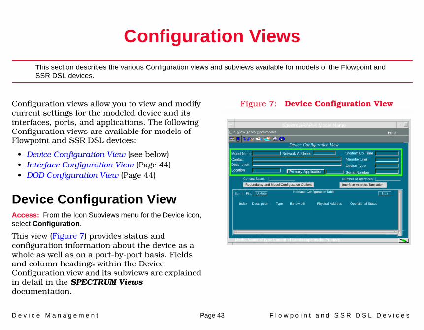
Configuration views allow you to view and modify current settings for the modeled device and its interfaces, ports, and applications. The following Configuration views are available for models of Flowpoint and SSR DSL devices:
• Device Configuration View (see below)• Interface Configuration View (Page 44)• DOD Configuration View (Page 44)
Device Configuration ViewAccess: From the Icon Subviews menu for the Device icon, select Configuration.
This view (Figure 7) provides status and configuration information about the device as a whole as well as on a port-by-port basis. Fields and column headings within the Device Configuration view and its subviews are explained in detail in the SPECTRUM Views documentation.
Figure 7: Device Configuration View
SpectroGRAPH: Model Name
Primary Application
System Up Time
Manufacturer
Device Type
Serial Number
Network AddressModel NameContactDescriptionLocation
Device Configuration View
Interface Configuration TableSort Find Update
File View Tools Bookmarks
Index Description Type Bandwidth Physical Address Operational Status
Model Name of type Lucent of Landscape node: Primary
Help
Redundancy and Model Configuration Options Interface Address Tanslation Contact Status Number of Interfaces
C o n f i g u r a t i o n V i e w s I n t e r f a c e C o n f i g u r a t i o n V i e w
D e v i c e M a n a g e m e n t Page 44 F l o w p o i n t a n d S S R D S L D e v i c e s
Interface Configuration ViewAccess: From the Icon Subviews menu for a selected Interface icon in the Interface Device view, select IF Configuration.
This view provides the following information for the selected interface:
Operation StatusThe current operational state of the interface (On, Off, or Testing).
Admin. StatusThe desired operational state of the interface (On, Off, or Testing).
Last ChangeThe System UpTime value when the interface entered its current operational state.
IP Address/Network MaskThis window provides a list of the user-defined names and IP addresses for the interface.
Physical AddressThe Ethernet (MAC) address of the interface.
BandwidthThe estimated bandwidth of the interface, measured in bits per second. For interfaces that do not vary in bandwidth, or for which no
accurate estimate can be made, a nominal bandwidth is provided.
Packet SizeThe largest packet that can be transmitted or received by the port, displayed in octets.
Queue LengthThe length of the outbound packet queue, in packets.
DOD Configuration ViewAccess: From the Icon Subviews menu for the dodApp Application icon, select DOD Configuration.
This view contains the following information:
Table IDThe identifier number of the remote destination.
Destination NameA description of the remote destination.
Authen ProtocolThe minimum authentication protocol this remote connection is using. Possible values are: chap, pap, and none.
Max LinksThe maximum number of links to be used when the system dials out or accepts incoming calls.
C o n f i g u r a t i o n V i e w s D O D C o n f i g u r a t i o n V i e w
D e v i c e M a n a g e m e n t Page 45 F l o w p o i n t a n d S S R D S L D e v i c e s
BW ThresholdAn established link’s bandwidth utilization. This value (0 - 100) is utilized for triggering additional links. A value of zero means all available links are dialed while 100 means no additional links are used.
Prefer TypeThe preferred type of connection.
Tear Down TimerThe timeout limit (in seconds) to tear down this link when there is no activity for the link.
Source IP AddressThe local IP address of the WAN interface.
Remote IP AddressThe remote IP address of the WAN interface.
Source IP MaskThe local IP net mask of the WAN interface.
Remote IP MaskThe remote IP net mask of the WAN interface.
IPX Net AddressThe IPX net address associated with the WAN link when connected to this remote.
IP FiltersNumber of IP filters currently defined for this remote.
IPX FiltersNumber of IPX filters currently defined for this remote.
Remote IP NetsThe number of static IP routing entries for this Destination Name or connection.
Remote IPX NetsThe number of static IPX routing entries for this Destination Name or connection.
Remote IPX SAPs The number of static IPX SAP entries for this destination.
Remote Mac StateEnables or disables the current bridge state for this destination.
Remote MacsNumber of specific MAC addresses that are statically bridged to this remote.
Last Activity TimeThe last “activity time” with this destination.
Min LinksThe minimum number of links to be used when this system dials out or accepts incoming calls.
C o n f i g u r a t i o n V i e w s D O D C o n f i g u r a t i o n V i e w
D e v i c e M a n a g e m e n t Page 46 F l o w p o i n t a n d S S R D S L D e v i c e s
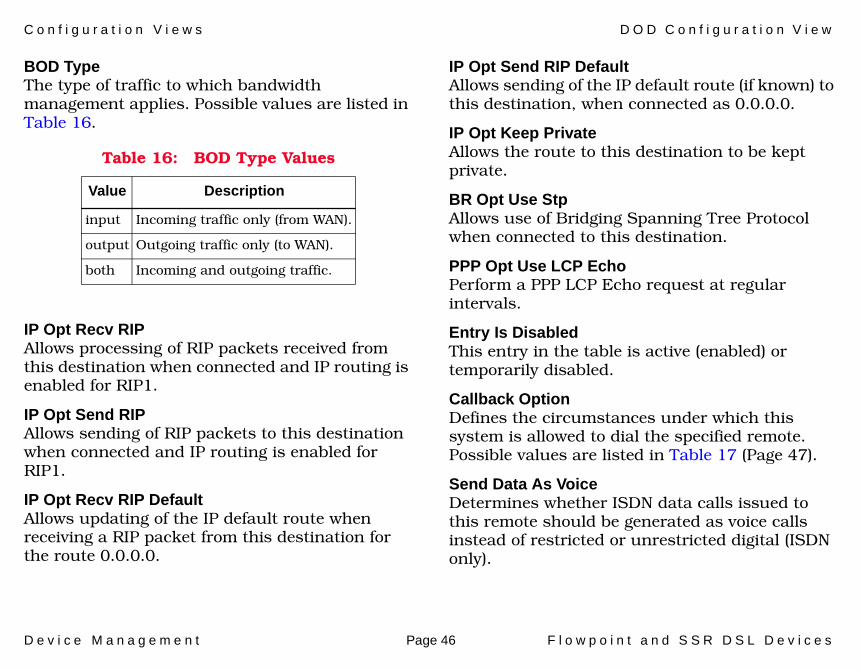
BOD TypeThe type of traffic to which bandwidth management applies. Possible values are listed in Table 16.
IP Opt Recv RIPAllows processing of RIP packets received from this destination when connected and IP routing is enabled for RIP1.
IP Opt Send RIPAllows sending of RIP packets to this destination when connected and IP routing is enabled for RIP1.
IP Opt Recv RIP DefaultAllows updating of the IP default route when receiving a RIP packet from this destination for the route 0.0.0.0.
IP Opt Send RIP Default Allows sending of the IP default route (if known) to this destination, when connected as 0.0.0.0.
IP Opt Keep PrivateAllows the route to this destination to be kept private.
BR Opt Use StpAllows use of Bridging Spanning Tree Protocol when connected to this destination.
PPP Opt Use LCP EchoPerform a PPP LCP Echo request at regular intervals.
Entry Is DisabledThis entry in the table is active (enabled) or temporarily disabled.
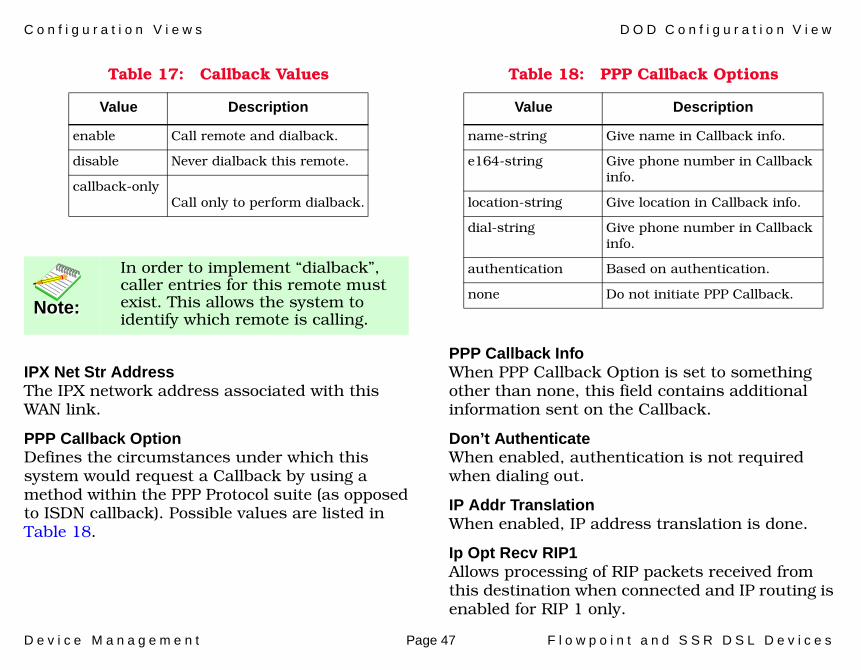
Callback OptionDefines the circumstances under which this system is allowed to dial the specified remote. Possible values are listed in Table 17 (Page 47).
Send Data As VoiceDetermines whether ISDN data calls issued to this remote should be generated as voice calls instead of restricted or unrestricted digital (ISDN only).
Table 16: BOD Type Values
Value Description
input Incoming traffic only (from WAN).
output Outgoing traffic only (to WAN).
both Incoming and outgoing traffic.
C o n f i g u r a t i o n V i e w s D O D C o n f i g u r a t i o n V i e w
D e v i c e M a n a g e m e n t Page 47 F l o w p o i n t a n d S S R D S L D e v i c e s
IPX Net Str AddressThe IPX network address associated with this WAN link.
PPP Callback OptionDefines the circumstances under which this system would request a Callback by using a method within the PPP Protocol suite (as opposed to ISDN callback). Possible values are listed in Table 18.
PPP Callback InfoWhen PPP Callback Option is set to something other than none, this field contains additional information sent on the Callback.
Don’t AuthenticateWhen enabled, authentication is not required when dialing out.
IP Addr TranslationWhen enabled, IP address translation is done.
Ip Opt Recv RIP1Allows processing of RIP packets received from this destination when connected and IP routing is enabled for RIP 1 only.
Table 17: Callback Values
Value Description
enable Call remote and dialback.
disable Never dialback this remote.
callback-only Call only to perform dialback.
Note:Note:
In order to implement “dialback”, caller entries for this remote must exist. This allows the system to identify which remote is calling.
Table 18: PPP Callback Options
Value Description
name-string Give name in Callback info.
e164-string Give phone number in Callback info.
location-string Give location in Callback info.
dial-string Give phone number in Callback info.
authentication Based on authentication.
none Do not initiate PPP Callback.
C o n f i g u r a t i o n V i e w s D O D C o n f i g u r a t i o n V i e w
D e v i c e M a n a g e m e n t Page 48 F l o w p o i n t a n d S S R D S L D e v i c e s
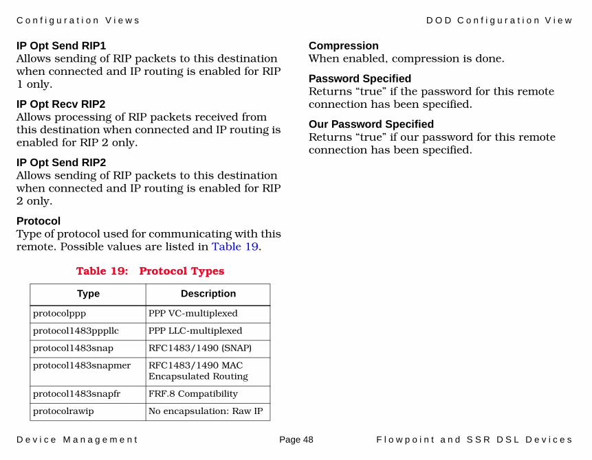
IP Opt Send RIP1Allows sending of RIP packets to this destination when connected and IP routing is enabled for RIP 1 only.
IP Opt Recv RIP2Allows processing of RIP packets received from this destination when connected and IP routing is enabled for RIP 2 only.
IP Opt Send RIP2Allows sending of RIP packets to this destination when connected and IP routing is enabled for RIP 2 only.
ProtocolType of protocol used for communicating with this remote. Possible values are listed in Table 19.
CompressionWhen enabled, compression is done.
Password SpecifiedReturns “true” if the password for this remote connection has been specified.
Our Password SpecifiedReturns “true” if our password for this remote connection has been specified.
Table 19: Protocol Types
Type Description
protocolppp PPP VC-multiplexed
protocol1483pppllc PPP LLC-multiplexed
protocol1483snap RFC1483/1490 (SNAP)
protocol1483snapmer RFC1483/1490 MAC Encapsulated Routing
protocol1483snapfr FRF.8 Compatibility
protocolrawip No encapsulation: Raw IP

D e v i c e M a n a g e m e n t Page 49 F l o w p o i n t a n d S S R D S L D e v i c e s
Model Information Views
This section provides a brief description of the Model Information views available for models of the Flowpoint and SSR devices.
Model Information views provide descriptive and configuration information about models of devices, interfaces, and applications. Figure 8 shows an example of a Model Information view accessed from the Icon Subviews menu for the FP2200 model’s Device icon. Model Information views are also available for each of the Interface icons in the Interface Device and Interface Device Topology views, and for each of the Application icons in the Application view. Although these views may vary slightly, depending on the particular entity being modeled, their basic layout and content are similar for most SPECTRUM management modules. Therefore, these views are described in more detail in SPECTRUM Views.
Figure 8: Model Information View
Primary Application
System Up Time
Manufacturer
Device Type
Serial Number
Network AddressModel Name
ContactDescription
Location
MM Version Number
MM Name
MM Part Number
General Information
Model Created By
Model Type
Model Creation Time
Model State
Security String
Communication Information
Community Name
DCM TimeOut
DCM Retry
Poll/Log Information
Poll Interval
Polling StatusCondition
Condition Value
Contact Status
Lost Child Count
Value When Yellow
Value When Orange
Value When Red
Last Successful Poll
Log Ratio
LOGGED POLLED
Model Information View
SpectroGRAPH: Model Name
File View Tools Bookmarks Help
type Model Type of Landscape: Primary
D e v i c e M a n a g e m e n t Page 50 F l o w p o i n t a n d S S R D S L D e v i c e s
Index
AAddress
Interface IP 12Physical (MAC) 12
Admin Status 11Administrative Status button 12allowing Bridging Spanning Tree
Protocol 46allowing system advertising 21Application view ?? to 40applications
dhcpApp 23dirApp 23dodApp 29ipApp 29isdnApp 29loginApp 29potsApp 29SSRetherApp 20SSRsystemApp 23SSRwanApp 29
authentication override 23
BB channel status 38
boot firmware 19Bootp request packet 19bridge state, enabling/disabling 45Bridging Spanning Tree Protocol 46buttons
Administrative Status 12Update 13
CCall ID Table 32Callback 47CallerID/UDP Relay Information
view 26Callers Table view 34changing interface address 13changing interface mask 13changing IP address 13changing IP address of LAN
interface 21configuration of LAN interfaces 20Configuration views 43 to 48configuring devices
Configuration views 43Interface Device view 10Model Informaiton view 49
configuring DHCP Client Lease information 28
configuring DOD informationDOD Configuration view 44DOD Operation/Bridging view 31
configuring network address translation 22
configuring port informationInterface Device view 10Interface icon 11
configuring system information 23
Ddefining Callback circumstances 47Device Configuration view 43Device icon 10Device icon (described) 7Device views ?? to 13DHCP Server Client Option view 29DHCP Server Client view 28DHCP Server Global Option view 27DHCP Server Option view 26DHCP Server Subnet Option view 28DHCP Server Subnet view 27DHCP/Bootp Server, setting IP
address 25
I n d e x I n d e x
D e v i c e M a n a g e m e n t Page 51 F l o w p o i n t a n d S S R D S L D e v i c e s
dhcpApp application 23dialback 47dirApp application 23Directory Information view 29disabling forwarding of data
traffic 25disabling port 12disabling SNMP management of
router 25disabling Telnet connections to
router 25DOD Configuration view 44DOD NAT Host Mapping Table
view 34DOD Operation/Bridging view 31dodApp application 29download operations, status
values 18download, requesting 17downloadCompleteError value 19downloading information 17Dynamic Host Configuration
protocol (see DHCP) 26
Eenabling Bridging Spanning Tree
Protocol 46enabling port 12enabling/disabling bridge state 45
enabling/disabling internet firewall filter 24
Ethernet Information view 20Ethernet IP Translation Information
view 22Ethernet NAT Information view 22examining DOD information
DOD Configuration view 44DOD Operation/Bridging view 31
examining file transfers 17examining model information
Model Information view 49examining port 12examining port information
Interface Device view 10Interface icon 11
examining system information 23examining WAN information 30
Ffinding bridging status of LAN
port 20finding configuration of LAN
interfaces 20finding operational status of
interface 12finding reason for last reboot 20finding status of download
operations 18Flowpoint 2100 6
Flowpoint model types (differentiated) 6
Flowpoint system group information 23
forcing Bootp request packet 19forwarding data traffic,
setting/disabling 25
GGeneric_SSR_FP model type 7
Iicons
Device (described) 7Interface (described) 11
initiating 17initiating file transfers 17initiating reboot 17Interface
Type, Device 11Interface Configuration view 44Interface Device view 10Interface icon 11Interface Number label 11Interface Status view 12internet firewall filter,
enabling/disabling 24IP address of LAN interface 21
I n d e x I n d e x
D e v i c e M a n a g e m e n t Page 52 F l o w p o i n t a n d S S R D S L D e v i c e s
IP address, changing 13IP default route 46IP Filter Table view 33IP RIP 1 packets, processing 21IP RIP packets 21IP routing table 21ipApp application 29IPX external network number 21IPX Filter Table view 34IPX frame type 21IPX information 32ISDN Information view 38ISDN service status, setting 38isdnApp application 29
Kkeeping destination route private 46
Llabels
Interface Number 11Login Information view 37login password 24loginApp application 29
Mmasking IP network 21Model Information views 49monitoring device performance
Device views 10
NNetwork I/O ports 14Network Type 12
Ooperational status, interface 12
PPerformance Statistics 41Phone Information Table 32Phone/Call ID Information view 31Plain Old Telephone Service (see
POTS) 25port
enabling/disabling 12Port Number, Device 11POTS Information view 35POTS Interface Information view 36POTS ISDN channel 36
POTS Preempt Mode 35POTS state values 36potsApp appliction 29Preempt Mode (of POTS) 35processing IP RIP 1 packets 21processing IP RIP 2 packets 21
Rreal-time clock, setting 25reboot 17Remote IP Network Information
view 31Remote IPX Network Table view 32Remote IPX SAP Table view 33Remote MAC view 32requesting download 17retrieving IPX frame type 21rfc1533 28RIP packets 46running more than one WAN link at
a time 26
SSecondary Address Panel 13selecting operational state of
interface 12sending IP RIP 1 compatible
packet 21

I n d e x I n d e x
D e v i c e M a n a g e m e n t Page 53 F l o w p o i n t a n d S S R D S L D e v i c e s
sending IP RIP 1 packets 21sending IP RIP 2 packets 21sending ISDN data calls as voice 46Serial ports 14Server IP Translation Table view 34setting forwarding of data traffic 25setting IP address for LAN
interface 21setting IP address of client 24setting IP address of DHCP/Bootp
Server 25setting IPX external network
number 21setting IPX frame type 21setting ISDN service status 38setting real-time clock 25setting RIP 2 Multicast address 22setting SNMP community name 25SmartSwitch Router model types
(differentiated) 6SNMP community name 25SNMP management of router,
disabling 25socket (internal port number) 33SPECTRUM modeling 7spid number 38SSRetherApp application 20SSRsystemApp application 23SSRwanApp application 29Statistics
Routing Frame Transmission 42status, B channel 38
subnet pool. 28supported devices 6Sys Op values 23Sys password 23system information
examining applications 29Interface Configuration view 44
System Information view 23system information, examining 23
Ttables
Call ID Table 32Phone Information Table 32
tasks 8Telnet connections to router,
disabling 25type of service 33
UUDP broadcast traffic 26UDP port 26Update button 13updating IP default route 46updating IP routing table 21uploadCompleteError value 19uploading information 17
Vviews
CallerID/UDP Relay Information 26
Callers Table 34Device Configuration 43DHCP Server Client 28DHCP Server Client Option 29DHCP Server Global Option 27DHCP Server Option 26DHCP Server Subnet 27DHCP Server Subnet Option 28Directory Information 29DOD Configuration 44DOD NAT Host Mapping Table 34DOD Operation/Bridging 31Ethernet Information 20Ethernet IP Translation
Information 22Ethernet NAT Information 22Interface Configuration 44Interface Device 10Interface Status 12IP Filter Table 33IPX Filter Table 34ISDN Information 38Login Information 37Model Information 49Phone/Call ID Information 31POTS Information 35POTS Interface Information 36
I n d e x I n d e x
D e v i c e M a n a g e m e n t Page 54 F l o w p o i n t a n d S S R D S L D e v i c e s
Remote IP Network Information 31
Remote IPX Network Table 32Remote IPX SAP Table 33Remote MAC 32Server IP Translation Table 34System Information 23WAN Information 30
WWAN Information view 30