3COM LANPlex Switch - CA...
57
3COM LANPlex Switch Device Management Supports Management Module SM-3CM1006 Titlepae
Transcript of 3COM LANPlex Switch - CA...
3COM LANPlex Switch
Device Management
Supports Management Module SM-3CM1006
Titlep
ae
D e v i c e M a n a g e m e n t Page 2 3 C o m L A N p l e x S w i t c h
Copyright NoticeDocument 9032145-03. Copyright © June 2002 by Aprisma Management Technologies, Inc. All rights reserved worldwide. Use, duplication, or disclosure by the United States government is subject to the restrictions set forth in DFARS 252.227-7013(c)(1)(ii) and FAR 52.227-19.Liability DisclaimerAprisma Management Technologies, Inc. (“Aprisma”) reserves the right to make changes in specifications and other information contained in this document without prior notice. In all cases, the reader should contact Aprisma to inquire if any changes have been made.The hardware, firmware, or software described in this manual is subject to change without notice.IN NO EVENT SHALL APRISMA, ITS EMPLOYEES, OFFICERS, DIRECTORS, AGENTS, OR AFFILIATES BE LIABLE FOR ANY INCIDENTAL, INDIRECT, SPECIAL, OR CONSEQUENTIAL DAMAGES WHATSOEVER (INCLUDING BUT NOT LIMITED TO LOST PROFITS) ARISING OUT OF OR RELATED TO THIS MANUAL OR THE INFORMATION CONTAINED IN IT, EVEN IF APRISMA HAS BEEN ADVISED OF, HAS KNOWN, OR SHOULD HAVE KNOWN, THE POSSIBILITY OF SUCH DAMAGES.Trademark, Service Mark, and Logo InformationSPECTRUM, IMT, and the SPECTRUM IMT/VNM logo are registered trademarks of Aprisma Management Technologies, Inc., or its affiliates. APRISMA, APRISMA MANAGEMENT TECHNOLOGIES, the APRISMA MANAGEMENT TECHNOLOGIES logo, MANAGE WHAT MATTERS, DCM, VNM, SpectroGRAPH, SpectroSERVER, Inductive Modeling Technology, Device Communications Manager, SPECTRUM Security Manager, and Virtual Network Machine are unregistered trademarks of Aprisma Management Technologies, Inc., or its affiliates. For a complete list of Aprisma trademarks, service marks, and trade names, go tohttp://www.aprisma.com/manuals/trademark-list.htm.
All referenced trademarks, service marks, and trade names identified in this document, whether registered or unregistered, are the intellectual property of their respective owners. No rights are granted by Aprisma Management Technologies, Inc., to use such marks, whether by implication, estoppel, or otherwise. If you have comments or concerns
about trademark or copyright references, please send an e-mail to [email protected]; we will do our best to help.Restricted Rights Notice(Applicable to licenses to the United States government only.)
This software and/or user documentation is/are provided with RESTRICTED AND LIMITED RIGHTS. Use, duplication, or disclosure by the government is subject to restrictions as set forth in FAR 52.227-14 (June 1987) Alternate III(g)(3) (June 1987), FAR 52.227-19 (June 1987), or DFARS 52.227-7013(c)(1)(ii) (June 1988), and/or in similar or successor clauses in the FAR or DFARS, or in the DOD or NASA FAR Supplement, as applicable. Contractor/manufacturer is Aprisma Management Technologies, Inc. In the event the government seeks to obtain the software pursuant to standard commercial practice, this software agreement, instead of the noted regulatory clauses, shall control the terms of the government's license.
Virus DisclaimerAprisma makes no representations or warranties to the effect that the licensed software is virus-free.Aprisma has tested its software with current virus-checking technologies. However, because no antivirus system is 100 percent effective, we strongly recommend that you write-protect the licensed software and verify (with an antivirus system in which you have confidence) that the licensed software, prior to installation, is virus-free.Contact InformationAprisma Management Technologies, Inc.273 Corporate DrivePortsmouth, NH 03801Phone: 603-334-2100U.S. toll-free: 877-468-1448Web site: http://www.aprisma.com
D e v i c e M a n a g e m e n t Page 3 3 C O M L A N P l e x S w i t c h
ContentsINTRODUCTION 5
Purpose and Scope ........................................................5Required Reading ...........................................................5Supported Devices..........................................................6The SPECTRUM Model ..................................................7
TASKS 9
DEVICE VIEWS 10
Interface Device View ...................................................10Interface Icons ..............................................................11
Interface Icon Subviews Menu ..................................12Interface Status View.................................................13Secondary Address Panel .........................................13
Chassis Device View ....................................................13Chassis Module Icons ...............................................14
Module Identification Labels ..................................14Interface Label Icon Subviews Menu .....................14
Port Icons ..................................................................15Port Labels.............................................................15
Port Label Icon Subviews Menu.........................15Interface Status View .............................................16Interface Threshold View .......................................16
DEVICE TOPOLOGY VIEW 17
Interface Device Topology View ...................................17
Chassis Device Topology View..................................... 18
APPLICATION VIEWS 19
Supported Applications ................................................. 20Common Applications ............................................... 20Device-Specific MIBs ................................................ 21
Switch 6012 Interface Application (Lp4xIfApp) ............. 22Chassis Configuration View ...................................... 22
Hub Interface Configuration................................... 23Core Builder 2500 Interface Application (Lp4x2IfApp)..23
Chassis Configuration View ...................................... 23Interface Table ................................................... 23
Bridge Port Information View ................................. 24Address Table Size ............................................ 24
Ethernet Port Configuration View .......................... 25Core Builder 3500 Interface Applications (Lp4x3IfApp) 26
QOS Configuration View ...........................................26Class Table ........................................................26Control Table......................................................26
QOS Flow Class View ...........................................27QOS RSVP View ................................................... 28QOS Transmit Statistics View................................ 29QOS Receive Statistics View................................. 30
SMT Port Application (Lp4x2SMTPApp).......................30 Fddi Port Attributes View.......................................... 30
LER Info View ........................................................31
C o n t e n t s C o n t e n t s
D e v i c e M a n a g e m e n t Page 4 3 C O M L A N P l e x S w i t c h
Ring Latency View.....................................................32Ring Op Count View ..................................................32
Virtual LAN Application (3ComVLANApp).....................333COM VLAN MIB View..............................................33
IP VLAN Table .......................................................34Core Builder Chassis Application (CBldr_Chas) ...........34
Chassis Configuration View.......................................34Interface Table ...................................................34
System Information View .......................................35Processor Board Memory...................................36System Revision Levels .....................................36SNMP Mode .......................................................36Environmental Conditions ..................................37System Reset .....................................................37PSU Table ..........................................................37
Agent Information View..........................................37Trap Enterprise Info............................................38Trap Destination Information Table ....................39
Bridge Port Information View .................................39Address Table Size ............................................40Bridge Port Table View.......................................40Bridge Port ‘Forwarded To’ View........................42Bridge Port Address View ..................................42LAN Port Address Detail View............................43LANplex Bridge Port Detail View........................44
IP Interface Information View.................................45Configured IP Interface Table ............................45
Address View .........................................................46Address Table ....................................................46
SWITCH OPTIONS 48
PERFORMANCE VIEWS 49
Device Performance View ............................................ 50Port Performance View ................................................ 50Ethernet Port Performance Summary View ................. 50
CONFIGURATION VIEWS 51
Device Configuration View ........................................... 51Interface Configuration View ........................................ 52Module Configuration View .......................................... 52
MODEL INFORMATION VIEW 54
INDEX 55
D e v i c e M a n a g e m e n t Page 5 3 C O M L A N P l e x S w i t c h
Introduction
This section introduces the SPECTRUM Device Management documentation for the LANplex Switch manufactured by 3COM.
This introduction contains the following topics:
• Purpose and Scope
• Required Reading
• Supported Devices (Page 6)
• The SPECTRUM Model (Page 7)
Purpose and ScopeUse this document as a guide for managing the 3COM LANplex switch devices described on Page 6 with SPECTRUM management module SM-3CM1006. This document describes the icons, menus, and views that enable you to remotely monitor, configure, and troubleshoot 3COM LANplex switch devices through software models in your SPECTRUM database.
Information specific to SM-3CM1006 is what is primarily included in this document. For general information about device management using SPECTRUM and explanations of SPECTRUM
functionality and navigation techniques, refer to the topics listed under Required Reading.
Required ReadingTo use this documentation effectively, you must be familiar with the information covered by the other SPECTRUM online documents listed below.
• Getting Started with SPECTRUM for Operators
• Getting Started with SPECTRUM for Administrators
• How to Manage Your Network with SPECTRUM
• SPECTRUM Views
• SPECTRUM Menus
• SPECTRUM Icons
• SPECTRUM Software Release Notice
I n t r o d u c t i o n S u p p o r t e d D e v i c e s
D e v i c e M a n a g e m e n t Page 6 3 C O M L A N P l e x S w i t c h
Supported DevicesSPECTRUM management module SM-3CM1006 currently lets you model the 3COM LANplex switches. The LANplex family of switches blends high-speed switching and bridging between Ethernet LANs, bridging between Ethernet and Fiber Distributed Data Interface (FDDI) LANs, FDDI concentrators, and FDDI backbone connections - all in one chassis.
SuperStack 3900-24. This switch contains 24 10/100 Mbps Ethernet/Fast Ethernet ports and an integral 1000BASE-SX port and two Gigabit Ethernet expansion slots.
SuperStack 3900-36. This switch contains 36 10/100 Mbps Ethernet/Fast Ethernet ports and an integral 1000BASE-SX port and two Gigabit Ethernet expansion slots.
CoreBuilder 6000. These switches (Lanplex 6012 and 6004) contain 12 and 4 slots respectively. Switching options range from 10 Mbps Ethernet or 16 Mbps Token Ring to dedicated 100 Mbps Fast Ethernet, 100 Mbps FDDI, or 155 Mbps ATM connections.
CoreBuilder 2500. Switching options range from 10 Mbps Ethernet or 16 Mbps Token Ring to dedicated 100 Mbps Fast Ethernet,
100 Mbps FDDI, or 155 Mbps ATM connec-tions.
CoreBuilder 3500. Provides up to 24 Ether-net/Fast Ethernet, up to 4 Gigabit Ethernet, up to 24 FDDI SAS/ 12 FDDI DAS, up to 4 ATM OC3c/ 2 ATM OC12c. Contains an embedded web server for direct management
CoreBuilder 9400. A Gigabit Ethernet full line rate switch among 24 ports with a fixed configuration. Provides 12 1000Base-SX ports 12 1000BaseGBIC that can accept LX or SX transceivers. Ports may be trunked (max 6 ports per trunk).
LinkSwitch 2000. Switching hub which holds up to a maximum of 16-Ethernet ports.
I n t r o d u c t i o n T h e S P E C T R U M M o d e l
D e v i c e M a n a g e m e n t Page 7 3 C O M L A N P l e x S w i t c h
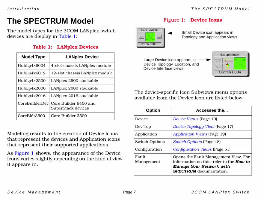
The SPECTRUM ModelThe model types for the 3COM LANplex switch devices are display in Table 1:
Modeling results in the creation of Device icons that represent the devices and Application icons that represent their supported applications.
As Figure 1 shows, the appearance of the Device icons varies slightly depending on the kind of view it appears in.
Figure 1: Device Icons
The device-specific Icon Subviews menu options available from the Device icon are listed below.
Table 1: LANplex Devices
Model Type LANplex Device
HubLp4x6004 4-slot chassis LANplex module
HubLp4x6012 12-slot chassis LANplex module
HubLp4x2500 LANplex 2500 stackable
HubLp4x2000 LANplex 2000 stackable
HubLp4x2016 LANplex 2016 stackable
CoreBuilderDev Core Builder 9400 and SuperStack devices
CoreBldr3500 Core Builder 3500Option Accesses the...
Device Device Views (Page 10)
Dev Top Device Topology View (Page 17)
Application Application Views (Page 19)
Switch Options Switch Options (Page 48)
Configuration Configuration Views (Page 51)
Fault Management
Opens the Fault Management View. For information on this, refer to the How to Manage Your Network with SPECTRUM documentation.
Switch 6004
HubLp4x6004
Switch 6004
Small Device icon appears inTopology and Application views
Large Device icon appears inDevice Topology, Location, andDevice Interface views.
HubLp4x6004
I n t r o d u c t i o n T h e S P E C T R U M M o d e l
D e v i c e M a n a g e m e n t Page 8 3 C O M L A N P l e x S w i t c h
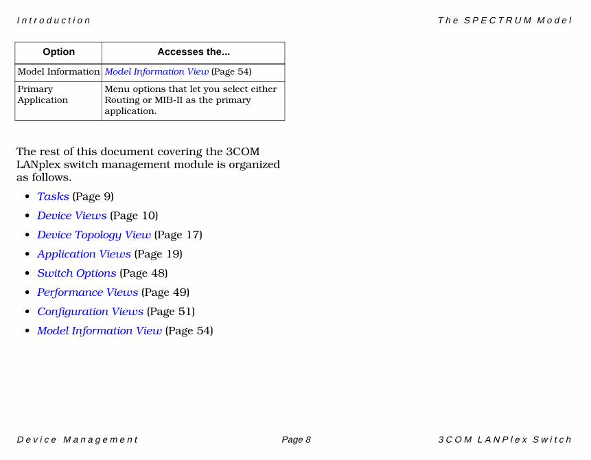
The rest of this document covering the 3COM LANplex switch management module is organized as follows.
• Tasks (Page 9)
• Device Views (Page 10)
• Device Topology View (Page 17)
• Application Views (Page 19)
• Switch Options (Page 48)
• Performance Views (Page 49)
• Configuration Views (Page 51)
• Model Information View (Page 54)
Model Information Model Information View (Page 54)
Primary Application
Menu options that let you select either Routing or MIB-II as the primary application.
Option Accesses the...
D e v i c e M a n a g e m e n t Page 9 3 C O M L A N P l e x S w i t c h
Tasks
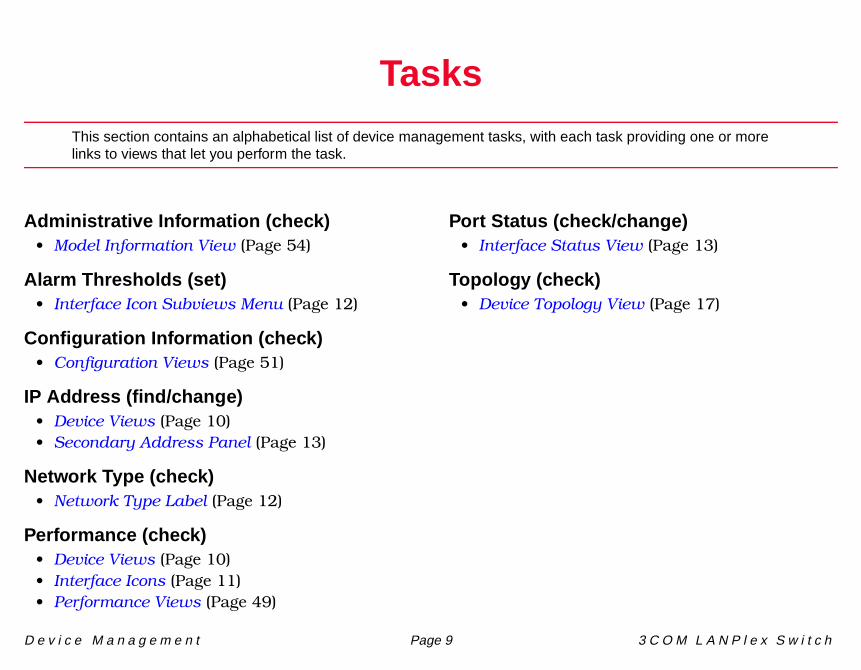
This section contains an alphabetical list of device management tasks, with each task providing one or more links to views that let you perform the task.
Administrative Information (check)• Model Information View (Page 54)
Alarm Thresholds (set)• Interface Icon Subviews Menu (Page 12)
Configuration Information (check)• Configuration Views (Page 51)
IP Address (find/change)• Device Views (Page 10)• Secondary Address Panel (Page 13)
Network Type (check)• Network Type Label (Page 12)
Performance (check)• Device Views (Page 10)• Interface Icons (Page 11)• Performance Views (Page 49)
Port Status (check/change)• Interface Status View (Page 13)
Topology (check)• Device Topology View (Page 17)
D e v i c e M a n a g e m e n t Page 10 3 C O M L A N P l e x S w i t c h
Device Views
This section describes the Device views and subviews available for models of 3COM LANplex switch devices in SPECTRUM.
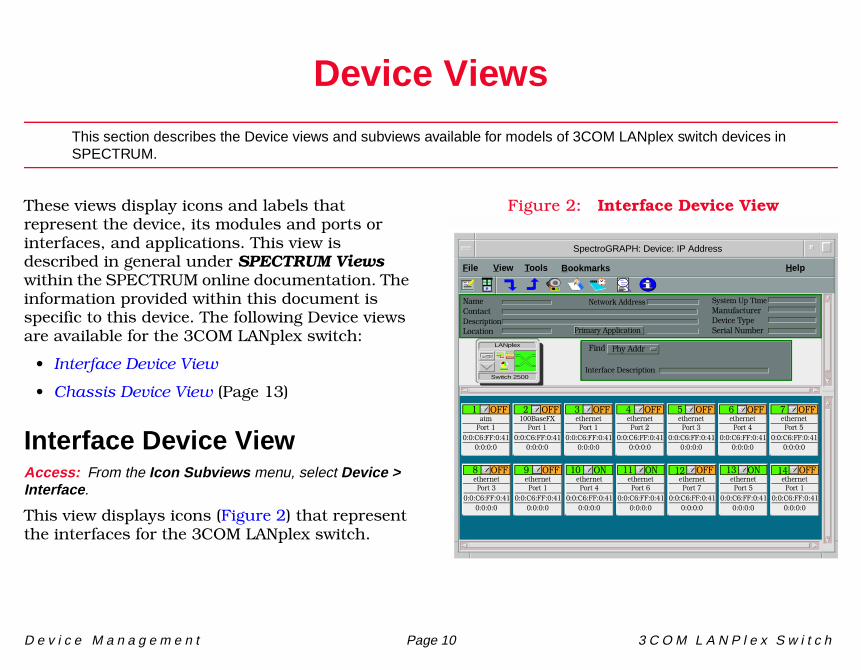
These views display icons and labels that represent the device, its modules and ports or interfaces, and applications. This view is described in general under SPECTRUM Views within the SPECTRUM online documentation. The information provided within this document is specific to this device. The following Device views are available for the 3COM LANplex switch:
• Interface Device View
• Chassis Device View (Page 13)
Interface Device View Access: From the Icon Subviews menu, select Device > Interface.
This view displays icons (Figure 2) that represent the interfaces for the 3COM LANplex switch.
Figure 2: Interface Device View
SpectroGRAPH: Device: IP Address
File View Help Tools
Interface Description
Find Phy AddrLANplex
Switch 2500
Bookmarks
NameContactDescriptionLocation
System Up TimeManufacturerDevice TypeSerial Number
Network Address
Primary Application
1 OFFatm
0:0:C6:FF:0:410:0:0:0
Port 1
2 OFF100BaseFX
0:0:C6:FF:0:410:0:0:0
Port 1
3 OFFethernet
0:0:C6:FF:0:410:0:0:0
Port 1
4 OFFethernet
0:0:C6:FF:0:410:0:0:0
Port 2
5 OFFethernet
0:0:C6:FF:0:410:0:0:0
Port 3
6 OFFethernet
0:0:C6:FF:0:410:0:0:0
Port 4
7 OFFethernet
0:0:C6:FF:0:410:0:0:0
Port 5
8 OFFethernet
0:0:C6:FF:0:410:0:0:0
Port 3
9 OFFethernet
0:0:C6:FF:0:410:0:0:0
Port 1
10 ONethernet
0:0:C6:FF:0:410:0:0:0
Port 4
11 ONethernet
0:0:C6:FF:0:410:0:0:0
Port 6
12 OFFethernet
0:0:C6:FF:0:410:0:0:0
Port 7
13 ONethernet
0:0:C6:FF:0:410:0:0:0
Port 5
14 OFFethernet
0:0:C6:FF:0:410:0:0:0
Port 1
D e v i c e V i e w s I n t e r f a c e I c o n s
D e v i c e M a n a g e m e n t Page 11 3 C O M L A N P l e x S w i t c h
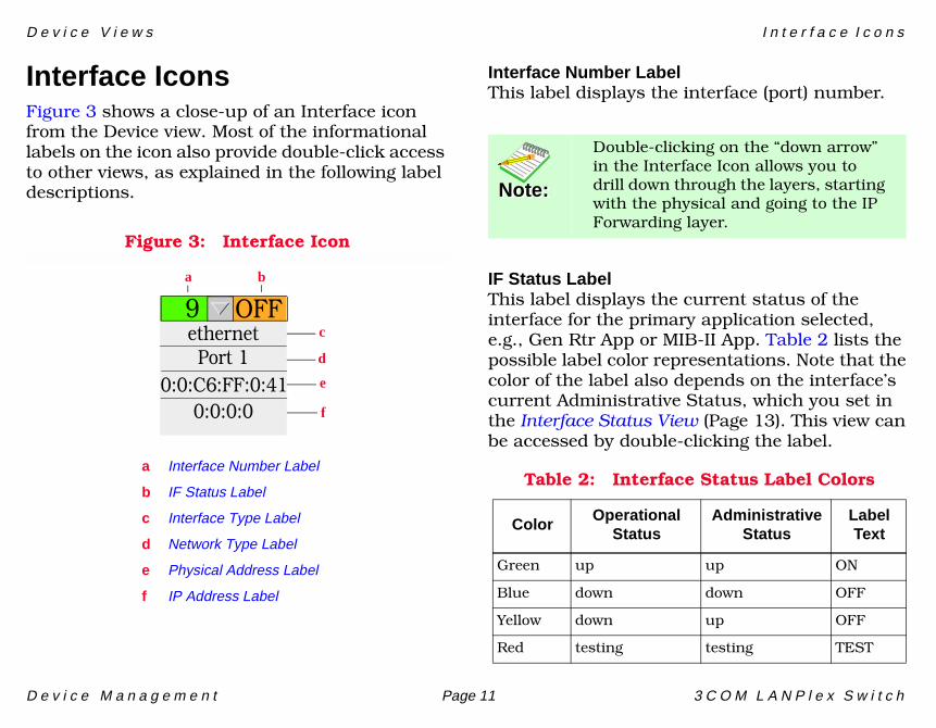
Interface IconsFigure 3 shows a close-up of an Interface icon from the Device view. Most of the informational labels on the icon also provide double-click access to other views, as explained in the following label descriptions.
Figure 3: Interface Icon
Interface Number LabelThis label displays the interface (port) number.
IF Status LabelThis label displays the current status of the interface for the primary application selected, e.g., Gen Rtr App or MIB-II App. Table 2 lists the possible label color representations. Note that the color of the label also depends on the interface’s current Administrative Status, which you set in the Interface Status View (Page 13). This view can be accessed by double-clicking the label.
c
f
ba
a Interface Number Label
b IF Status Label
c Interface Type Label
d Network Type Label
e Physical Address Label
f IP Address Label
d
e
9 OFFethernet
0:0:C6:FF:0:410:0:0:0
Port 1
Note:Note:
Double-clicking on the “down arrow” in the Interface Icon allows you to drill down through the layers, starting with the physical and going to the IP Forwarding layer.
Table 2: Interface Status Label Colors
Color OperationalStatus
AdministrativeStatus
LabelText
Green up up ON
Blue down down OFF
Yellow down up OFF
Red testing testing TEST
D e v i c e V i e w s I n t e r f a c e I c o n s
D e v i c e M a n a g e m e n t Page 12 3 C O M L A N P l e x S w i t c h
Interface Type LabelThis label identifies the interface type (Ethernet, ATM, etc.). Double-click this label to access the Interface Configuration View (Page 52).
Network Type LabelThis label identifies the type of network to which the interface is connected. Double-click the label to open the Model Information view for the interface.
Physical Address LabelThis label displays the physical (MAC) address of the interface. Double-click this label to open the IF Address Translation Table.
IP Address LabelThis label displays the IP address for the interface. Double-click this label to open the Secondary Address Panel (Page 13), which lets you change the address and mask for the interface.
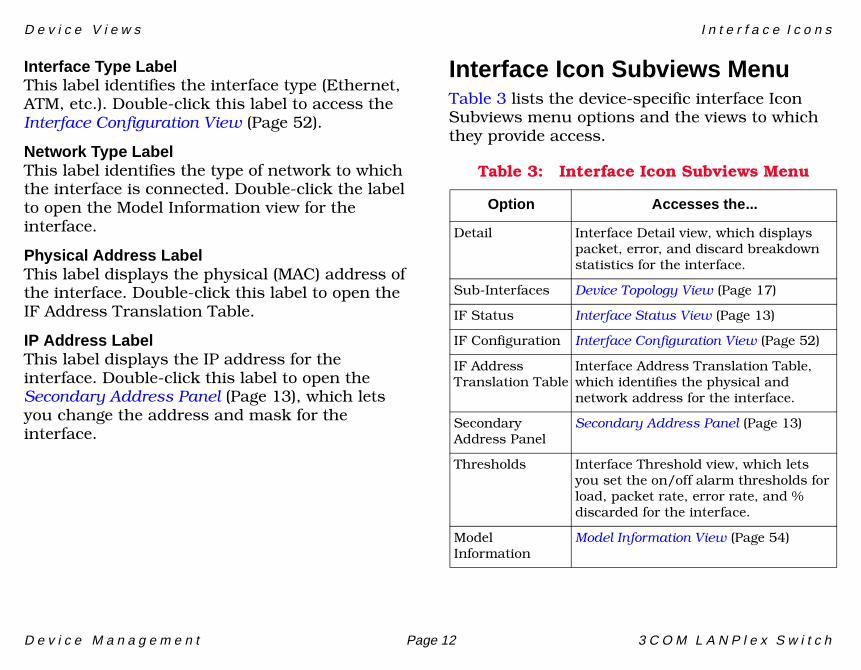
Interface Icon Subviews MenuTable 3 lists the device-specific interface Icon Subviews menu options and the views to which they provide access.
Table 3: Interface Icon Subviews Menu
Option Accesses the...
Detail Interface Detail view, which displays packet, error, and discard breakdown statistics for the interface.
Sub-Interfaces Device Topology View (Page 17)
IF Status Interface Status View (Page 13)
IF Configuration Interface Configuration View (Page 52)
IF Address Translation Table
Interface Address Translation Table, which identifies the physical and network address for the interface.
Secondary Address Panel
Secondary Address Panel (Page 13)
Thresholds Interface Threshold view, which lets you set the on/off alarm thresholds for load, packet rate, error rate, and % discarded for the interface.
Model Information
Model Information View (Page 54)
D e v i c e V i e w s C h a s s i s D e v i c e V i e w
D e v i c e M a n a g e m e n t Page 13 3 C O M L A N P l e x S w i t c h
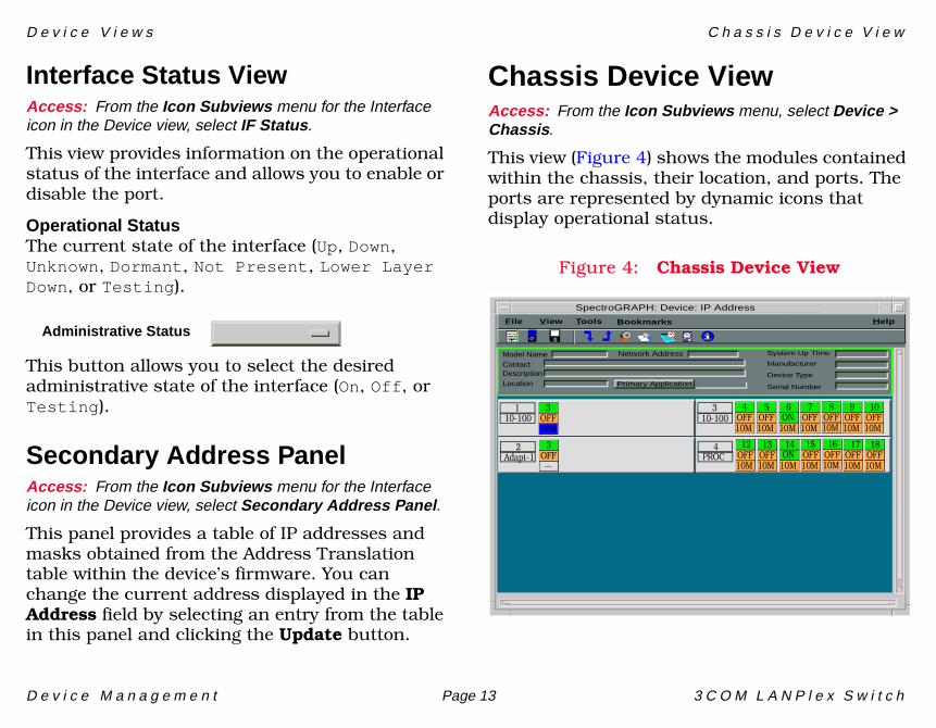
Interface Status ViewAccess: From the Icon Subviews menu for the Interface icon in the Device view, select IF Status.
This view provides information on the operational status of the interface and allows you to enable or disable the port.
Operational StatusThe current state of the interface (Up, Down, Unknown, Dormant, Not Present, Lower Layer Down, or Testing).
This button allows you to select the desired administrative state of the interface (On, Off, or Testing).
Secondary Address PanelAccess: From the Icon Subviews menu for the Interface icon in the Device view, select Secondary Address Panel.
This panel provides a table of IP addresses and masks obtained from the Address Translation table within the device’s firmware. You can change the current address displayed in the IP Address field by selecting an entry from the table in this panel and clicking the Update button.
Chassis Device ViewAccess: From the Icon Subviews menu, select Device > Chassis.
This view (Figure 4) shows the modules contained within the chassis, their location, and ports. The ports are represented by dynamic icons that display operational status.
Figure 4: Chassis Device View
Administrative Status
SpectroGRAPH: Device: IP Address
Primary Application
System Up Time
Manufacturer
Device Type
Serial Number
Network AddressModel NameContactDescriptionLocation
File View HelpTools Bookmarks
110-100
Adapt-12
310-100
PROC4
3OFF100M
3OFF__
4OFF10M
5OFF10M
6ON
10M
7OFF10M
8OFF10M
9OFF10M
10OFF10M
12OFF10M
13OFF10M
14ON
10M
15OFF10M
16OFF10M
17OFF10M
18OFF10M
D e v i c e V i e w s C h a s s i s D e v i c e V i e w
D e v i c e M a n a g e m e n t Page 14 3 C O M L A N P l e x S w i t c h
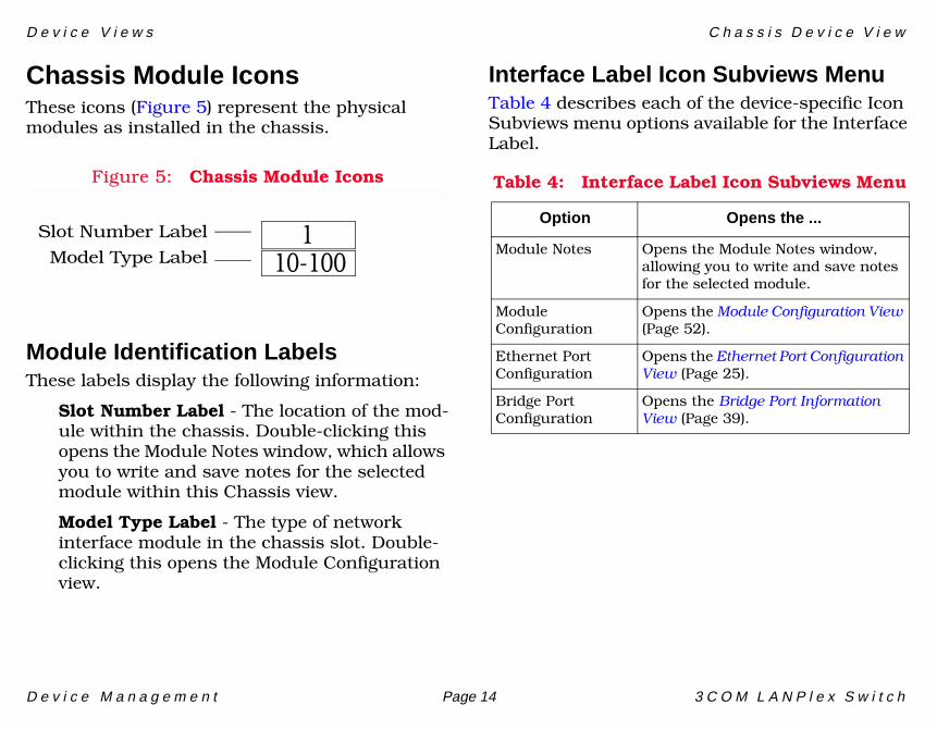
Chassis Module IconsThese icons (Figure 5) represent the physical modules as installed in the chassis.
Figure 5: Chassis Module Icons
Module Identification LabelsThese labels display the following information:
Slot Number Label - The location of the mod-ule within the chassis. Double-clicking this opens the Module Notes window, which allows you to write and save notes for the selected module within this Chassis view.
Model Type Label - The type of network interface module in the chassis slot. Double-clicking this opens the Module Configuration view.
Interface Label Icon Subviews Menu Table 4 describes each of the device-specific Icon Subviews menu options available for the Interface Label.
110-100
Slot Number Label
Model Type Label
Table 4: Interface Label Icon Subviews Menu
Option Opens the ...
Module Notes Opens the Module Notes window, allowing you to write and save notes for the selected module.
Module Configuration
Opens the Module Configuration View (Page 52).
Ethernet Port Configuration
Opens the Ethernet Port Configuration View (Page 25).
Bridge Port Configuration
Opens the Bridge Port Information View (Page 39).
D e v i c e V i e w s C h a s s i s D e v i c e V i e w
D e v i c e M a n a g e m e n t Page 15 3 C O M L A N P l e x S w i t c h
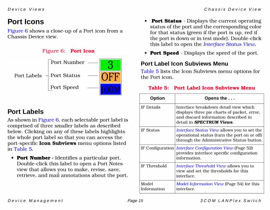
Port IconsFigure 6 shows a close-up of a Port icon from a Chassis Device view.
Figure 6: Port Icon
Port LabelsAs shown in Figure 6, each selectable port label is comprised of three smaller labels as described below. Clicking on any of these labels highlights the whole port label so that you can access the port-specific Icon Subviews menu options listed in Table 5.
• Port Number - Identifies a particular port. Double-click this label to open a Port Notes view that allows you to make, revise, save, retrieve, and mail annotations about the port.
• Port Status - Displays the current operating status of the port and the corresponding color for that status (green if the port is up, red if the port is down or in test mode). Double-click this label to open the Interface Status View.
• Port Speed - Displays the speed of the port.
Port Label Icon Subviews MenuTable 5 lists the Icon Subviews menu options for the Port icon.Port Labels
Port Number
Port Status
Port Speed
3OFF100M Table 5: Port Label Icon Subviews Menu
Option Opens the . . .
IF Details Interface breakdown detail view which displays three pie charts of packet, error, and discard information described in detail in SPECTRUM Views.
IF Status Interface Status View allows you to set the operational status (turn the port on or off) through the Administrative Status button.
IF Configuration Interface Configuration View (Page 52) provides interface specific configuration information.
IF Threshold Interface Threshold View allows you to view and set the thresholds for this interface.
Model Information
Model Information View (Page 54) for this interface.
D e v i c e V i e w s C h a s s i s D e v i c e V i e w
D e v i c e M a n a g e m e n t Page 16 3 C O M L A N P l e x S w i t c h
Interface Status ViewAccess: From the Icon Subviews menu for the Interface icon in the Interface Device view, select IF Status.
The Interface Status view provides the following information on the status of the interface:
Operational StatusDisplays the current operational state of the interface is displayed (On, Off, or Testing).
Administrative StatusAllows you to select the desired operational state of the interface (On, Off, or Testing).
Interface Threshold ViewAccess: From the Icon Subviews menu for the Interface icon in the Interface Device view, select IF Thresholds.
The Interface Threshold view allows a user to set statistical thresholds on a per interface basis with the File > Save All Changes feature.
• Load• Packet Rate• Error Rate• % Discarded
D e v i c e M a n a g e m e n t Page 17 3 C O M L A N P l e x S w i t c h
Device Topology View
This section describes the Device Topology views available for models of the 3COM LANplex switch devices.
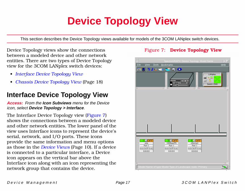
Device Topology views show the connections between a modeled device and other network entities. There are two types of Device Topology view for the 3COM LANplex switch devices:
• Interface Device Topology View
• Chassis Device Topology View (Page 18)
Interface Device Topology ViewAccess: From the Icon Subviews menu for the Device icon, select Device Topology > Interface.
The Interface Device Topology view (Figure 7) shows the connections between a modeled device and other network entities. The lower panel of the view uses Interface icons to represent the device’s serial, network, and I/O ports. These icons provide the same information and menu options as those in the Device Views (Page 10). If a device is connected to a particular interface, a Device icon appears on the vertical bar above the Interface icon along with an icon representing the network group that contains the device.
Figure 7: Device Topology View
File View HelpTools
Switch 2500
LANplex
Bookmarks
SpectroGRAPH: Device Topology: Model Name
Model Name of type Model Type of Landscape node: Primary
1 OFFatm
0:0:C6:FF:0:410:0:0:0
Port 1
3 OFF100BaseFX
0:0:C6:FF:0:410:0:0:0
Port 1
4 OFFethernet
0:0:C6:FF:0:410:0:0:0
Port 1
Switch 2500
D e v i c e T o p o l o g y V i e w C h a s s i s D e v i c e T o p o l o g y V i e w
D e v i c e M a n a g e m e n t Page 18 3 C O M L A N P l e x S w i t c h
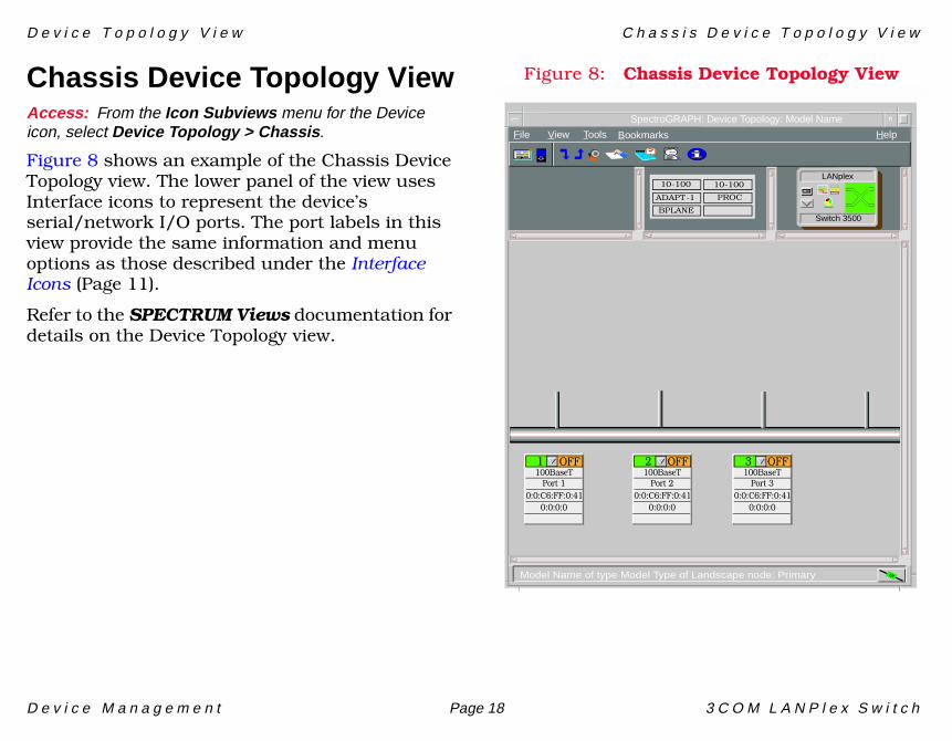
Chassis Device Topology ViewAccess: From the Icon Subviews menu for the Device icon, select Device Topology > Chassis.
Figure 8 shows an example of the Chassis Device Topology view. The lower panel of the view uses Interface icons to represent the device’s serial/network I/O ports. The port labels in this view provide the same information and menu options as those described under the Interface Icons (Page 11).
Refer to the SPECTRUM Views documentation for details on the Device Topology view.
Figure 8: Chassis Device Topology View
File View HelpTools
Switch 3500
LANplex
Bookmarks
SpectroGRAPH: Device Topology: Model Name
Model Name of type Model Type of Landscape node: Primary
1 OFF100BaseT
0:0:C6:FF:0:410:0:0:0
Port 1
2 OFF100BaseT
0:0:C6:FF:0:410:0:0:0
Port 2
3 OFF100BaseT
0:0:C6:FF:0:410:0:0:0
Port 3
10-100
ADAPT-1
BPLANE
10-100
PROC
D e v i c e M a n a g e m e n t Page 19 3 C O M L A N P l e x S w i t c h
Application Views
This section describes the main Application view and the associated application-specific subviews available for models of 3COM LANplex switch devices in SPECTRUM.
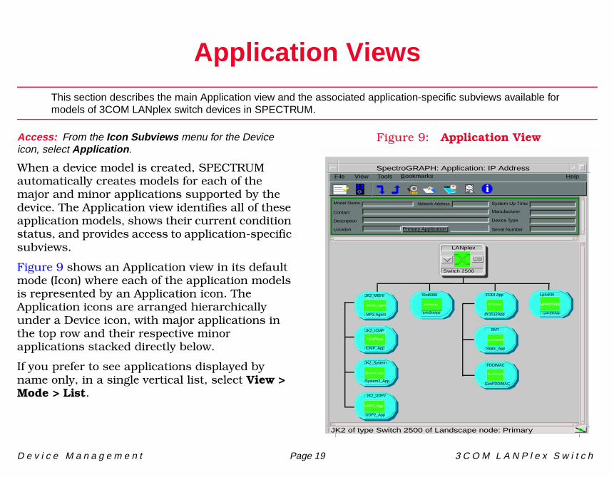
Access: From the Icon Subviews menu for the Device icon, select Application.
When a device model is created, SPECTRUM automatically creates models for each of the major and minor applications supported by the device. The Application view identifies all of these application models, shows their current condition status, and provides access to application-specific subviews.
Figure 9 shows an Application view in its default mode (Icon) where each of the application models is represented by an Application icon. The Application icons are arranged hierarchically under a Device icon, with major applications in the top row and their respective minor applications stacked directly below.
If you prefer to see applications displayed by name only, in a single vertical list, select View > Mode > List.
Figure 9: Application View
JK2 of type Switch 2500 of Landscape node: Primary
Model Name
Contact
Description
Location Primary Application
System Up Time
Manufacturer
Device Type
Serial Number
Network Address
File View HelpTools
LANplex
Switch 2500
JK2_MIB-II
MP2-Agent
JK2_ICMP
ICMP_App
FDDI AppSlot6000
Ip4xSlotApp
Ip4xSlotApp
Lp4xEth
Lp4xEthApp
Lp4xEthApp
SMT
FDDIMAC
rfc1512App
Static_App
GenFDDIMAC
SNMP2_Agent
ICMPApp
System2_App
UDP2_App
JK2_System
JK2_UDP2
System2_App
UDP2_App
Bookmarks
i
SpectroGRAPH: Application: IP Address
rfc1512App
GenFDDISMT
GenFDDIMAC
A p p l i c a t i o n V i e w s S u p p o r t e d A p p l i c a t i o n s
D e v i c e M a n a g e m e n t Page 20 3 C O M L A N P l e x S w i t c h
Supported ApplicationsSPECTRUM’s applications can be grouped within two general categories as follows:
• Applications associated with non proprietary MIBs. See Common Applications below.
• Applications associated with device-specific MIBs. See Device-Specific MIBs (Page 21).
Common ApplicationsFor the most part, these applications represent the non proprietary MIBs supported by your device. Listed below (beneath the title of the document that describes them) are some of the common applications currently supported by SPECTRUM.
• Routing Applications- Generic Routing- Repeater- AppleTalk- DECnet
- OSPF- OSPF2- BGP4- VRRP
• Bridging Applications- Ethernet Special Database- Spanning Tree- Static- Transparent- PPP Bridging- Source Routing- Translation- QBridge
• MIB II Applications- SNMP- IP- ICMP- TCP- System2- UDP
• Transmission Applications- FDDI- Point to Point- DS1- DS3- RS-232
Note:Note:
The documents listed are available for viewing at:
www.aprisma.com/manuals/
A p p l i c a t i o n V i e w s S u p p o r t e d A p p l i c a t i o n s
D e v i c e M a n a g e m e n t Page 21 3 C O M L A N P l e x S w i t c h
- WAN- Frame Relay- Token Ring- Ethernet- Fast Ethernet- rfc1317App- rfc1285App- rfc1315App- 802.11App- SONET
• Technology Applications- APPN- ATM Client- DHCP- PNNI- rfc1316App- DLSw
Device-Specific MIBsSPECTRUM imports the following device-level proprietary MIBs into its database:
• A3COM-SWITCHING-SYSTEMS-MIB • Lanplex Systems Management MIB • Lanplex Optional FDDI MIB for SMT
These MIBs can be used in conjunction with SPECTRUM’s optional customization products
(referred to as the Level I Tool Kits) to create application models and views that display the condition of selected MIB objects.
The following device-specific applications are described in the remainder of this section:
• Switch 6012 Interface Application (Lp4xIfApp) (Page 22)
• Core Builder 2500 Interface Application (Lp4x2IfApp) (Page 23)
• Core Builder 3500 Interface Applications (Lp4x3IfApp) (Page 26)
• SMT Port Application (Lp4x2SMTPApp) (Page 30)
• Virtual LAN Application (3ComVLANApp) (Page 33)
• Core Builder Chassis Application (CBldr_Chas) (Page 34)
Note:Note:
Aprisma Management Technologies can provide training, technical assistance, and custom engineering support services for creating application models and their associated views.
A p p l i c a t i o n V i e w s S w i t c h 6 0 1 2 I n t e r f a c e A p p l i c a t i o n ( L p 4 x I f A p p )
D e v i c e M a n a g e m e n t Page 22 3 C O M L A N P l e x S w i t c h
Switch 6012 Interface Application (Lp4xIfApp)This major application (model type Lp4xIfApp) has a two minor applications: the Ethernet Application (model Lp4xEthApp) and Optimum FDDI Application (model Lp4OptFApp). The Icon Subviews menu for this application provides access to the following application-specific subview:
• Chassis Configuration View
• Ethernet Port Configuration View (Page 25)
• Fddi Port Attributes View (Page 30)
• Ring Latency View (Page 32)
• Ring Op Count View (Page 32)
Chassis Configuration ViewAccess: From the Icon Subviews menu for the Lp4xIfApp Application icon, select Configuration.
This view contains the Interface Table and provides the following information:
IndexThe value of the MIB-II interface index for this entry.
NameA textual name for the class.
AbbrevThe abbreviation used to describe the board occupying this slot.
StatusThe current status of the board. Valid values are: On-line, Off-line, Testing or Empty.
RevisionThe board revision number.
FDDI MacsThe number of FDDI MAC ports on the board occupying this slot.
FDDI PortsThe number of FDDI ports on the board occupying this slot.
A p p l i c a t i o n V i e w s C o r e B u i l d e r 2 5 0 0 I n t e r f a c e A p p l i c a t i o n ( L p 4 x 2 I f A p p )
D e v i c e M a n a g e m e n t Page 23 3 C O M L A N P l e x S w i t c h
Eth PortsThe number of ethernet ports occupying this slot.
Temp StatusThe temperature status of the slot. If the slot does not support a temperature status, the value is False.
Opens the Hub Interface Configuration.
This button will re-configure the chassis.
Hub Interface ConfigurationAccess: From the Chassis Configuration, select the Hub Interfaces Table button.
IndexThe value of the MIB-II interface index for this entry.
Type The physical implementation of the interface is displayed: FDDIMac, Ethernet, or Other.
LocationThe type of location where the interface is physically located. Valid values are: Chassis, Modslot, ModCard, or Other.
Slot LocalThe slot number for this interface.
Core Builder 2500 Interface Application (Lp4x2IfApp)This major application (model type Lp4x2IfApp) has a single minor application: the Ethernet Application (model Lp4xEthApp). The Icon Subviews menu for this application provides access to the following application-specific subview:
• Chassis Configuration View
Chassis Configuration ViewAccess: From the Icon Subviews menu for the Lp4x2IfApp Application icon, select Configuration.
This view contains the Interface Table and provides the following information:
Interface TableThis table provides the following information:
IndexThe value of the MIB-II interface index for this entry.
Hub Interfaces Table
Reconfigure Chassis
A p p l i c a t i o n V i e w s C o r e B u i l d e r 2 5 0 0 I n t e r f a c e A p p l i c a t i o n ( L p 4 x 2 I f A p p )
D e v i c e M a n a g e m e n t Page 24 3 C O M L A N P l e x S w i t c h
TypeThe physical implementation of the interface is displayed: FDDIMac, Ethernet, atmPort, ethernetPort or Other.
LocationThe type of location where the interface is physically located. Values are: Chassis, Modslot, ModCard, or Other.
SlotThe slot number for this interface.
LocalThe local index or port number for this interface.
Opens the Bridge Port Information View.
Opens the Ethernet Port Configuration View (Page 25).
This button will re-configure the chassis.
Bridge Port Information ViewAccess: From the Chassis Configuration View, select Bridge Port Information.
This view shows the Bridge Function table with the following information for each bridge managed by this agent. Double-clicking on an entity in the Bridge or Ports columns displays the LANplex Bridge Port view. Double-clicking on any other entry displays the LANplex Bridge Function Detail view. Fields in this view are updatable.
BridgeThe index for this agent’s bridge. The number of the port selected as the backbone segment port.
PortsThe number of bridge ports controlled by this agent’s bridge.
Address Table SizeThe four columns in this section provide information about the Address Table for each bridge listed.
MaxThe maximum size of the Address Table for the bridge.
ThresholdA reporting threshold for the total number of addresses known for the bridge. When this
Bridge Port Information
Ethernet Port Information
Reconfigure Chassis
A p p l i c a t i o n V i e w s C o r e B u i l d e r 2 5 0 0 I n t e r f a c e A p p l i c a t i o n ( L p 4 x 2 I f A p p )
D e v i c e M a n a g e m e n t Page 25 3 C O M L A N P l e x S w i t c h
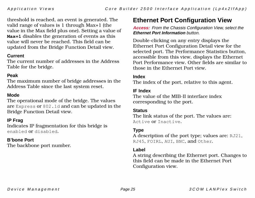
threshold is reached, an event is generated. The valid range of values is 1 through Max+1 (the value in the Max field plus one). Setting a value of Max+1 disables the generation of events as this value will never be reached. This field can be updated from the Bridge Function Detail view.
CurrentThe current number of addresses in the Address Table for the bridge.
PeakThe maximum number of bridge addresses in the Address Table since the last system reset.
ModeThe operational mode of the bridge. The values are Express or 802.1d and can be updated in the Bridge Function Detail view.
IP FragIndicates IP fragmentation for this bridge is enabled or disabled.
B’bone PortThe backbone port number.
Ethernet Port Configuration ViewAccess: From the Chassis Configuration View, select the Ethernet Port Information button.
Double-clicking on any entry displays the Ethernet Port Configuration Detail view for the selected port. The Performance Statistics button, accessible from this view, displays the Ethernet Port Performance view. Other fields are similar to those in the Ethernet Port view.
IndexThe index of the port, relative to this agent.
IF IndexThe value of the MIB-II interface index corresponding to the port.
StatusThe link status of the port. The values are: Active or Inactive.
TypeA description of the port type; values are: RJ21, RJ45, FOIRL, AUI, BNC, and Other.
LabelA string describing the Ethernet port. Changes to this field can be made in the Ethernet Port Configuration view.
A p p l i c a t i o n V i e w s C o r e B u i l d e r 3 5 0 0 I n t e r f a c e A p p l i c a t i o n s ( L p 4 x 3 I f A p p )
D e v i c e M a n a g e m e n t Page 26 3 C O M L A N P l e x S w i t c h
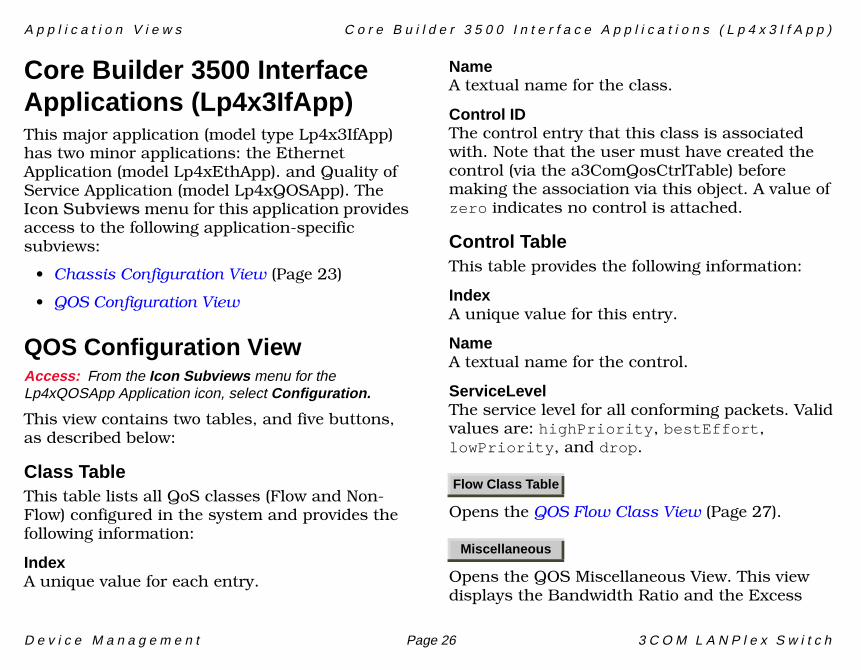
Core Builder 3500 Interface Applications (Lp4x3IfApp)This major application (model type Lp4x3IfApp) has two minor applications: the Ethernet Application (model Lp4xEthApp). and Quality of Service Application (model Lp4xQOSApp). The Icon Subviews menu for this application provides access to the following application-specific subviews:
• Chassis Configuration View (Page 23)
• QOS Configuration View
QOS Configuration ViewAccess: From the Icon Subviews menu for the Lp4xQOSApp Application icon, select Configuration.
This view contains two tables, and five buttons, as described below:
Class TableThis table lists all QoS classes (Flow and Non-Flow) configured in the system and provides the following information:
IndexA unique value for each entry.
NameA textual name for the class.
Control IDThe control entry that this class is associated with. Note that the user must have created the control (via the a3ComQosCtrlTable) before making the association via this object. A value of zero indicates no control is attached.
Control TableThis table provides the following information:
IndexA unique value for this entry.
NameA textual name for the control.
ServiceLevelThe service level for all conforming packets. Valid values are: highPriority, bestEffort, lowPriority, and drop.
Opens the QOS Flow Class View (Page 27).
Opens the QOS Miscellaneous View. This view displays the Bandwidth Ratio and the Excess
Flow Class Table
Miscellaneous

A p p l i c a t i o n V i e w s C o r e B u i l d e r 3 5 0 0 I n t e r f a c e A p p l i c a t i o n s ( L p 4 x 3 I f A p p )
D e v i c e M a n a g e m e n t Page 27 3 C O M L A N P l e x S w i t c h
Traffic Class Tag. Both of these fields can be changed.
Opens the QOS RSVP View (Page 28).
Opens the QOS Transmit Statistics View (Page 29).
Opens the QOS Receive Statistics View (Page 30).
QOS Flow Class ViewAccess: From the QOS Configuration View, select the Flow Class Table button.
This table lists the Flow classes defined in the system. Double-clicking on any entry in this table opens up the QOS Flow Class Detail view, which contains the same fields, and allows you to edit them.
This view provides the following information:
IndexA unique value for each entry. Flow classes use id values between 1-399.
FilterIndThe unique filter index associated with this class. Note that the maximum limit of 100 filters is the aggregate of all the filters defined in the system, not just the number of filters defined for this classifier.
CastThe network layer cast type for this class. Valid values are: unicast, multicast, and both.
IP ProtocolThe IP protocol type for this class. Valid values are: udp, tcp, and both.
Src AddressThe source IP address for this class.
Subnet MaskThe source subnet mask for this class.
Destination AddrThe destination IP address for this class.
Subnet MaskThe destination subnet mask for this class.
Port StartThe starting range of ports associated with this class. The default value is zero.
RSVP Group
Txmt Performance
Rcv Performance
A p p l i c a t i o n V i e w s C o r e B u i l d e r 3 5 0 0 I n t e r f a c e A p p l i c a t i o n s ( L p 4 x 3 I f A p p )
D e v i c e M a n a g e m e n t Page 28 3 C O M L A N P l e x S w i t c h
Port EndThe finishing range of ports associated with this class. The default value is 65535.
StatusThe status column for this entry. This object can be set to: createAndGo and destroy.
The following value may be read: active.
Setting this object to createAndGo creates a row in this table. The agent will allocate the next sequential filter index value for the newly created entry. Setting this object to destroy will remove this entry.
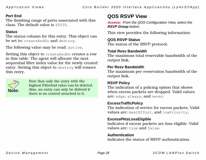
QOS RSVP ViewAccess: From the QOS Configuration View, select the RSVP Group button.
This view provides the following information:
QOS RSVP StatusThe status of the RSVP protocol.
Total Resv BandwidthThe maximum total reservable bandwidth of the output link.
Per Resv BandwidthThe maximum per-reservation bandwidth of the output link.
RSVP PolicyThe indication of a policing option that shows when excess packets are dropped. Valid values are: edge, always, and never.
ExcessTrafficPolicyThe indication of service for excess packets. Valid values are: bestEffort, and lowPriority.
ExcessPktsLossEligibleIndicates if excess packets are loss eligible. Valid values are: true and false.
AuthenticationIndicates the status of RSVP authentication.
Note:Note:
Note that only the entry with the highest FilterInd value can be deleted. Also, an entry can only be deleted if there is no control attached to it.
A p p l i c a t i o n V i e w s C o r e B u i l d e r 3 5 0 0 I n t e r f a c e A p p l i c a t i o n s ( L p 4 x 3 I f A p p )
D e v i c e M a n a g e m e n t Page 29 3 C O M L A N P l e x S w i t c h
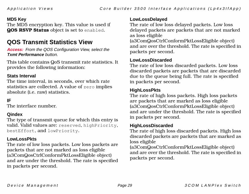
MD5 KeyThe MD5 encryption key. This value is used if QOS RSVP Status object is set to enabled.
QOS Transmit Statistics ViewAccess: From the QOS Configuration View, select the Txmt Performance button.
This table contains QoS transmit rate statistics. It provides the following information:
Stats IntervalThe time interval, in seconds, over which rate statistics are collected. A value of zero implies absolute (i.e. raw) statistics.
IFThe interface number.
QindexThe type of transmit queue for which this entry is valid. Valid values are: reserved, highPriority, bestEffort, and lowPriority.
LowLossPktsThe rate of low loss packets. Low loss packets are packets that are not marked as loss eligible (a3ComQosCtrlConformPktLossEligible object) and are under the threshold. The rate is specified in packets per second.
LowLossDelayedThe rate of low loss delayed packets. Low loss delayed packets are packets that are not marked as loss eligible (a3ComQosCtrlConformPktLossEligible object) and are over the threshold. The rate is specified in packets per second.
LowLossDiscardedThe rate of low loss discarded packets. Low loss discarded packets are packets that are discarded due to the queue being full. The rate is specified in packets per second.
HighLossPktsThe rate of high loss packets. High loss packets are packets that are marked as loss eligible (a3ComQosCtrlConformPktLossEligible object) and are under the threshold. The rate is specified in packets per second.
HighLossDiscardedThe rate of high loss discarded packets. High loss discarded packets are packets that are marked as loss eligible (a3ComQosCtrlConformPktLossEligible object) and are over the threshold. The rate is specified in packets per second.
A p p l i c a t i o n V i e w s S M T P o r t A p p l i c a t i o n ( L p 4 x 2 S M T P A p p )
D e v i c e M a n a g e m e n t Page 30 3 C O M L A N P l e x S w i t c h
QOS Receive Statistics ViewAccess: From the QOS Configuration View, select the Rcv Performance button.
This table contains the QoS receive rate statistics. It provides the following information:
Stats IntervalThe time interval, in seconds, over which rate statistics are collected. A value of zero implies absolute (i.e. raw) statistics.
IFThe interface number.
ConformBytesThe total conforming bytes receive rate. The rate is in bytes per second.
NonConfBytesFlowsThe non-conforming bytes receive rate for flows. The rate is in bytes per second.
NonConfBytesNonFlowsThe non-conforming bytes receive rate for non-flows. The rate is in bytes per second.
Dropped PacketsThe number of packets dropped. The rate is specified in packets per second.
SMT Port Application (Lp4x2SMTPApp)The LANplex SMT Port application has no sub-applications and supports three views:
• Fddi Port Attributes View
• Ring Latency View (Page 32)
• Ring Op Count View (Page 32)
The SMT Port Application views are described below.
Fddi Port Attributes ViewAccess: From the Icon Subviews menu for the Lp4x2SMTPApp Application icon, select Fddi Port Attributes.
Double-clicking on any entry displays the LANplex Fddi Port Attributes view for the selected port. The fields in this view are not updatable. Clicking on the More LER button displays the LER Info view, which is described later in this section.
SMTThe SMT index of the port described by this table entry.
A p p l i c a t i o n V i e w s S M T P o r t A p p l i c a t i o n ( L p 4 x 2 S M T P A p p )
D e v i c e M a n a g e m e n t Page 31 3 C O M L A N P l e x S w i t c h
PortA unique index for the port within a given SMT. This index value remains the same between system resets.
TypeThe type of this FDDI port. The values are: A, B, S, M, or Unknown.
NeighborThe type of this port’s neighbor port. The values are: A, B, S, M, or Unknown.
Connect StateThe Connect_State value for this port. The values are: Disabled, Connecting, Standby, or Active.
Current PathThe path for the port currently being displayed. The values are: Isolated, Local, Secondary, Primary, Concatenated, or Thru.
LER EstimateThe long term average link error rate, which ranges from 10^-4 (10 to the power of -4) through 10^-15.
LEM CountsThe aggregate link error count is displayed. The count is reset to zero only on system initialization.
EB ErrorsThe number of Elasticity Buffer errors.
PC WithholdThe value of PC_Withhold. Valid values are: Not-withheld, M-m, Otherincompatible, or Pathnotavailable.
LER Info ViewAccess: From the LANplex Fddi Port Attributes View, select the MORE LER button.
This view contains the following link error rate information for the selected port.
LER EstimateThis long term average link error rate ranges from 10^-4 (10 to the power of -4) through 10^-15.
LER FlagThis value is set to True when the value of LER Estimate is greater than or equal to the value in LER Alarm.
LER CutoffThe link error rate at which a link connection becomes broken. Updatable field settings range between 10^-4 and 10^-15. The default setting is 10^-7.
LER AlarmThe link error rate at which a link connection generates an alarm. Updatable field settings range between 10^-4 and 10^-15. The default setting is 10^-8.
A p p l i c a t i o n V i e w s S M T P o r t A p p l i c a t i o n ( L p 4 x 2 S M T P A p p )
D e v i c e M a n a g e m e n t Page 32 3 C O M L A N P l e x S w i t c h
Ring Latency ViewAccess: From the Icon Subviews menu for the Lp4xSMTPApp Application icon, select Ring Latency.
The LANplex Ring Latency view contains the following information for each PATH.
SMTThe SMT index number of the path described by this table entry (1 through 65535). The value remains constant between system resets.
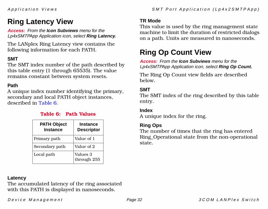
PathA unique index number identifying the primary, secondary and local PATH object instances, described in Table 6.
LatencyThe accumulated latency of the ring associated with this PATH is displayed in nanoseconds.
TR ModeThis value is used by the ring management state machine to limit the duration of restricted dialogs on a path. Units are measured in nanoseconds.
Ring Op Count ViewAccess: From the Icon Subviews menu for the Lp4xSMTPApp Application icon, select Ring Op Count.
The Ring Op Count view fields are described below.
SMTThe SMT index of the ring described by this table entry.
IndexA unique index for the ring.
Ring OpsThe number of times that the ring has entered Ring_Operational state from the non-operational state.
Table 6: Path Values
PATH Object Instance
Instance Descriptor
Primary path Value of 1
Secondary path Value of 2
Local path Values 3 through 255
A p p l i c a t i o n V i e w s V i r t u a l L A N A p p l i c a t i o n ( 3 C o m V L A N A p p )
D e v i c e M a n a g e m e n t Page 33 3 C O M L A N P l e x S w i t c h
Virtual LAN Application (3ComVLANApp)The VLAN application has no sub-applications and supports only one view, the 3COM VLAN MIB view, which is described below.
3COM VLAN MIB ViewAccess: From the Icon Subviews menu for the 3ComVLANApp Application icon, select Configuration.
Double-clicking on an entry in this view brings up the VLAN Detail View for the selected port. This view allows you to change the fields and it will subsequently update the 3COM VLAN MIB View.
IndexThe index value of this row and the VLAN’s ifIndex in the ifTable.
GlobalIDAn administratively assigned global VLAN identifier. For VLAN interfaces, on different network devices, which are part of the same globally identified VLAN, the value of this object will be the same.
The binding between a global identifier and a VLAN interface can be created or removed. To create a binding an NMS must write a non-zero
value to this object. To delete a binding, the NMS must write a zero to this object.
DescriptionThis is a description of the VLAN interface.
TypeThe VLAN interface type.
StatusThe status column for this VLAN interface. This object can be set to: active, createAndGo, createAndWait, and destroy.
The following values may be read: active, notInService, and notReady.
Setting this object to createAndGo causes the agent to attempt to create and commit the row based on the contents of the objects in the row. If all necessary information is present in the row and the values are acceptable to the agent, the agent will change the status to active. If any of the necessary objects are not available, the agent will reject the creation request.
Setting this object to createAndWait causes a row in this table to be created. The agent sets the status to notInService if all of the information is present in the row and the values are acceptable to the agent; otherwise, the agent sets the status to notReady.
A p p l i c a t i o n V i e w s C o r e B u i l d e r C h a s s i s A p p l i c a t i o n ( C B l d r _ C h a s )
D e v i c e M a n a g e m e n t Page 34 3 C O M L A N P l e x S w i t c h
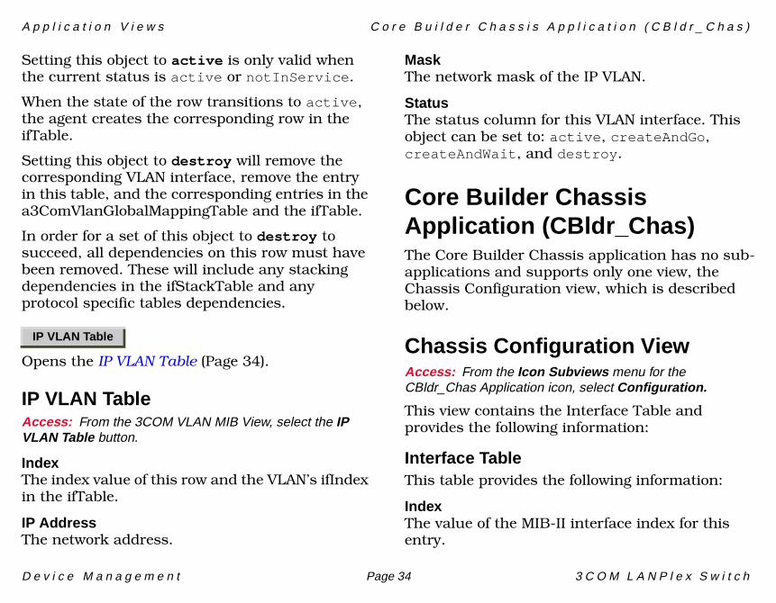
Setting this object to active is only valid when the current status is active or notInService.
When the state of the row transitions to active, the agent creates the corresponding row in the ifTable.
Setting this object to destroy will remove the corresponding VLAN interface, remove the entry in this table, and the corresponding entries in the a3ComVlanGlobalMappingTable and the ifTable.
In order for a set of this object to destroy to succeed, all dependencies on this row must have been removed. These will include any stacking dependencies in the ifStackTable and any protocol specific tables dependencies.
Opens the IP VLAN Table (Page 34).
IP VLAN TableAccess: From the 3COM VLAN MIB View, select the IP VLAN Table button.
IndexThe index value of this row and the VLAN’s ifIndex in the ifTable.
IP AddressThe network address.
MaskThe network mask of the IP VLAN.
StatusThe status column for this VLAN interface. This object can be set to: active, createAndGo, createAndWait, and destroy.
Core Builder Chassis Application (CBldr_Chas)The Core Builder Chassis application has no sub-applications and supports only one view, the Chassis Configuration view, which is described below.
Chassis Configuration ViewAccess: From the Icon Subviews menu for the CBldr_Chas Application icon, select Configuration.
This view contains the Interface Table and provides the following information:
Interface TableThis table provides the following information:
IndexThe value of the MIB-II interface index for this entry.
IP VLAN Table
A p p l i c a t i o n V i e w s C o r e B u i l d e r C h a s s i s A p p l i c a t i o n ( C B l d r _ C h a s )
D e v i c e M a n a g e m e n t Page 35 3 C O M L A N P l e x S w i t c h
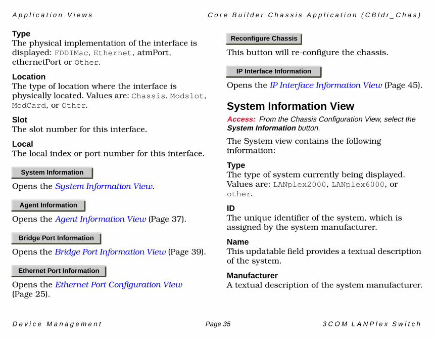
TypeThe physical implementation of the interface is displayed: FDDIMac, Ethernet, atmPort, ethernetPort or Other.
LocationThe type of location where the interface is physically located. Values are: Chassis, Modslot, ModCard, or Other.
SlotThe slot number for this interface.
LocalThe local index or port number for this interface.
Opens the System Information View.
Opens the Agent Information View (Page 37).
Opens the Bridge Port Information View (Page 39).
Opens the Ethernet Port Configuration View (Page 25).
This button will re-configure the chassis.
Opens the IP Interface Information View (Page 45).
System Information ViewAccess: From the Chassis Configuration View, select the System Information button.
The System view contains the following information:
TypeThe type of system currently being displayed. Values are: LANplex2000, LANplex6000, or other.
IDThe unique identifier of the system, which is assigned by the system manufacturer.
NameThis updatable field provides a textual description of the system.
ManufacturerA textual description of the system manufacturer.
System Information
Agent Information
Bridge Port Information
Ethernet Port Information
Reconfigure Chassis
IP Interface Information
A p p l i c a t i o n V i e w s C o r e B u i l d e r C h a s s i s A p p l i c a t i o n ( C B l d r _ C h a s )
D e v i c e M a n a g e m e n t Page 36 3 C O M L A N P l e x S w i t c h
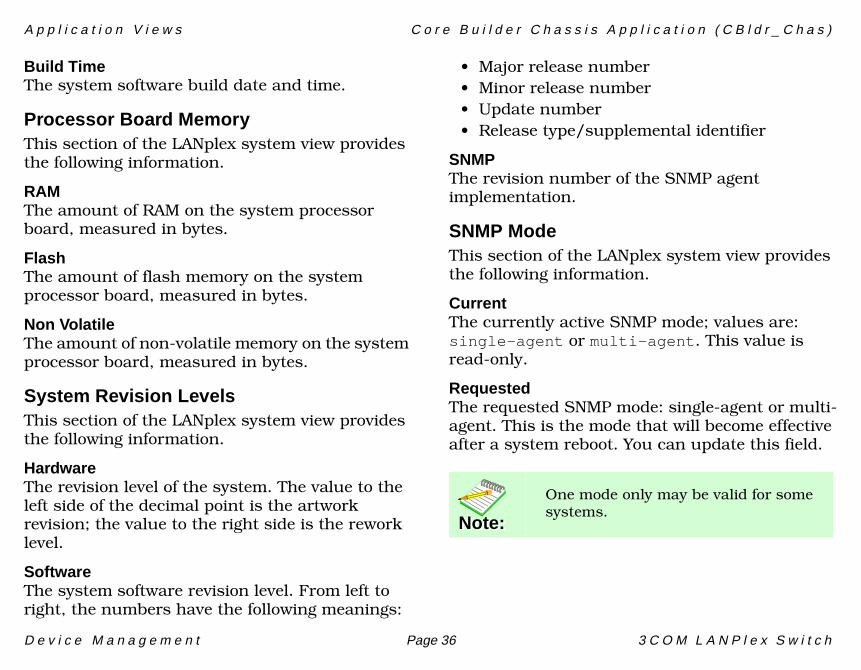
Build TimeThe system software build date and time.
Processor Board MemoryThis section of the LANplex system view provides the following information.
RAMThe amount of RAM on the system processor board, measured in bytes.
FlashThe amount of flash memory on the system processor board, measured in bytes.
Non VolatileThe amount of non-volatile memory on the system processor board, measured in bytes.
System Revision LevelsThis section of the LANplex system view provides the following information.
HardwareThe revision level of the system. The value to the left side of the decimal point is the artwork revision; the value to the right side is the rework level.
SoftwareThe system software revision level. From left to right, the numbers have the following meanings:
• Major release number• Minor release number• Update number• Release type/supplemental identifier
SNMPThe revision number of the SNMP agent implementation.
SNMP ModeThis section of the LANplex system view provides the following information.
CurrentThe currently active SNMP mode; values are: single-agent or multi-agent. This value is read-only.
RequestedThe requested SNMP mode: single-agent or multi-agent. This is the mode that will become effective after a system reboot. You can update this field.
Note:Note:
One mode only may be valid for some systems.
A p p l i c a t i o n V i e w s C o r e B u i l d e r C h a s s i s A p p l i c a t i o n ( C B l d r _ C h a s )
D e v i c e M a n a g e m e n t Page 37 3 C O M L A N P l e x S w i t c h
Environmental ConditionsThis section of the LANplex system view provides the following information.
Fan StatusThe status of the fan. Valid values are: OK, Failed, or NotSupported.
Temperature StatusThis field indicates the system temperature condition.
System ResetThis section of the LANplex system view provides the following information.
Reset ActionThe default system setting is no-reset. Updating the field to reset causes a system reset.
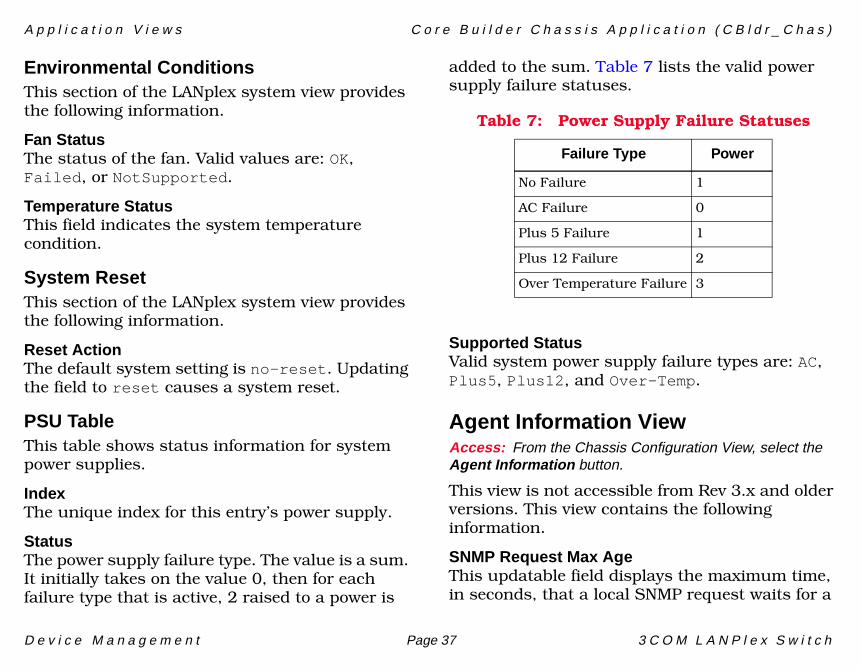
PSU TableThis table shows status information for system power supplies.
IndexThe unique index for this entry’s power supply.
StatusThe power supply failure type. The value is a sum. It initially takes on the value 0, then for each failure type that is active, 2 raised to a power is
added to the sum. Table 7 lists the valid power supply failure statuses.
Supported StatusValid system power supply failure types are: AC, Plus5, Plus12, and Over-Temp.
Agent Information ViewAccess: From the Chassis Configuration View, select the Agent Information button.
This view is not accessible from Rev 3.x and older versions. This view contains the following information.
SNMP Request Max AgeThis updatable field displays the maximum time, in seconds, that a local SNMP request waits for a
Table 7: Power Supply Failure Statuses
Failure Type Power
No Failure 1
AC Failure 0
Plus 5 Failure 1
Plus 12 Failure 2
Over Temperature Failure 3
A p p l i c a t i o n V i e w s C o r e B u i l d e r C h a s s i s A p p l i c a t i o n ( C B l d r _ C h a s )
D e v i c e M a n a g e m e n t Page 38 3 C O M L A N P l e x S w i t c h
response before being discarded. Values range from 1 through 255.
Proxy Remote SMT RequestsThis updatable field shows whether the agent proxies SMT requests to other FDDI stations. Values are: True or False.
Proxy Remote SMT Max AgeThis updatable field displays the maximum time, in seconds, that an SMT proxy request waits for a response before being discarded. Values range from 1 through 255.
Proxy Remote SMT EventsThis updatable field shows whether the agent is generating traps for SMT events occurring at other stations. If set to True, traps are generated for SMT events occurring locally and at other
stations. If this field is set to False, traps are only generated for local SMT events.
Trap Enterprise InfoThis table contains information relating a trap index to a specific trap enterprise OID and trap number. The table contains an entry for every trap supported by the system.
IndexA unique index corresponding to the trap described by this table entry. This value remains constant after system resets.
OIDThe enterprise under which the trap is defined.
Note:Note:
Some systems cannot proxy SMT requests.
Note:Note:
When the Proxy Remote SMT Requests field is set to False, the value in this field is ignored.
Note:Note:
Some systems cannot generate traps for all SMT events.
Note:Note:
In most cases (except for generic MIB-II traps), the enterprise under which a trap is defined is the same as that appearing in the ENTERPRISE portion of the trap.
A p p l i c a t i o n V i e w s C o r e B u i l d e r C h a s s i s A p p l i c a t i o n ( C B l d r _ C h a s )
D e v i c e M a n a g e m e n t Page 39 3 C O M L A N P l e x S w i t c h
NumberThe number of the trap identified by this entry, within the defined enterprise.
Trap Destination Information TableThis table shows all traps being transmitted to a specified destination address. The table is indexed by destination address type and destination address. Each entry with a status of Valid identifies a set of traps which, when generated, are transmitted to the listed destination address.
Double-clicking on any table entry displays the LANplex Trap Destination Detail view. Clicking the table Update button updates the Trap Mask and deletes entries. The Trap Index field refers to the Index in the Trap Enterprise Info table.
Dest AddrThe address for the identified set of traps being transmitted.
TypeThe type of IP address.
MaskThe bit string identifying the set of traps. The string is a 64-bit sum and defaults to 0. For each enabled trap, 2 raised to the value of Index-1 (Index as shown in the Trap Enterprise Info table)
for that trap is added to the sum. The field can be updated in the LANplex Trap Destination Detail view.
StatusShows the status for the set of traps being transmitted.
Clicking on the Add Destination Entry button opens the LANplex Add Trap Destination view and displays instructions for adding entries to the Trap Destination Info table.
Bridge Port Information ViewAccess: From the Chassis Configuration View, select the Bridge Information button.
This view shows the Bridge Function table with the following information for each bridge managed by this agent. Double-clicking on an entity in the Bridge or Ports columns displays the LANplex Bridge Port view. Double-clicking on any
Note:Note:A string of zeroes is NOT a valid value.
Add Destination Entry
A p p l i c a t i o n V i e w s C o r e B u i l d e r C h a s s i s A p p l i c a t i o n ( C B l d r _ C h a s )
D e v i c e M a n a g e m e n t Page 40 3 C O M L A N P l e x S w i t c h
other entry displays the LANplex Bridge Function Detail view. Fields in this view are updatable.
BridgeThe index for this agent’s bridge. The number of the port selected as the backbone segment port.
PortsThe number of bridge ports controlled by this agent’s bridge.
Address Table SizeThe four columns in this section provide information about the Address Table for each bridge listed.
MaxThe maximum size of the Address Table for the bridge.
ThresholdA reporting threshold for the total number of addresses known for the bridge. When this threshold is reached, an event is generated. The valid range of values is 1 through Max+1 (the value in the Max field plus one). Setting a value of Max+1 disables the generation of events as this value will never be reached. This field can be updated from the Bridge Function Detail view.
CurrentThe current number of addresses in the Address Table for the bridge.
PeakThe maximum number of bridge addresses in the Address Table since the last system reset.
ModeThe operational mode of the bridge. The values are Express or 802.1d and can be updated in the Bridge Function Detail view.
IP FragIndicates IP fragmentation for this bridge is enabled or disabled.
Bridge Port Table ViewAccess: By double-clicking a Bridge or Ports entry in the Bridge Function View.
The Bridge Port view contains the following information for each port managed by the selected bridge.
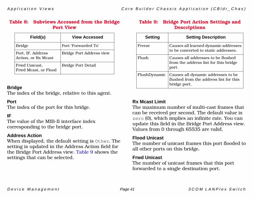
Table 8 shows a description of the sub-views accessible from fields within this view. These sub-views are described later in this chapter.
A p p l i c a t i o n V i e w s C o r e B u i l d e r C h a s s i s A p p l i c a t i o n ( C B l d r _ C h a s )
D e v i c e M a n a g e m e n t Page 41 3 C O M L A N P l e x S w i t c h
BridgeThe index of the bridge, relative to this agent.
PortThe index of the port for this bridge.
IF The value of the MIB-II interface index corresponding to the bridge port.
Address ActionWhen displayed, the default setting is Other. The setting is updated in the Address Action field for the Bridge Port Address view. Table 9 shows the settings that can be selected.
Rx Mcast LimitThe maximum number of multi-cast frames that can be received per second. The default value is zero (0), which implies an infinite rate. You can update this field in the Bridge Port Address view. Values from 0 through 65535 are valid.
Flood UnicastThe number of unicast frames this port flooded to all other ports on this bridge.
Frwd UnicastThe number of unicast frames that this port forwarded to a single destination port.
Table 8: Subviews Accessed from the Bridge Port View
Field(s) View Accessed
Bridge Port ‘Forwarded To’
Port, IF, Address Action, or Rx Mcast
Bridge Port Address view
Frwd Unicast,Frwd Mcast, or Flood
Bridge Port Detail
Table 9: Bridge Port Action Settings and Descriptions
Setting Setting Description
Freeze Causes all learned dynamic addresses to be converted to static addresses.
Flush Causes all addresses to be flushed from the address list for this bridge port.
FlushDynamic Causes all dynamic addresses to be flushed from the address list for this bridge port.
A p p l i c a t i o n V i e w s C o r e B u i l d e r C h a s s i s A p p l i c a t i o n ( C B l d r _ C h a s )
D e v i c e M a n a g e m e n t Page 42 3 C O M L A N P l e x S w i t c h
Frwd McastThe number of multicast frames that this port forwarded.
Bridge Port ‘Forwarded To’ ViewAccess: By double-clicking a Bridge entry in the Bridge Port View.
Statistics are displayed for each port pair combination within the bridge, and cannot be modified in this view.
BridgeThe index of the bridge, relative to this agent.
PortThe index of the receiving bridge port.
Dest PortThe index of the destination bridge port.
FramesThe number of unicast frames forwarded from the receiving port to the destination port is displayed.
OctetsThe number of octets contained in unicast frames forwarded from the receiving port to the destination port is displayed.
Bridge Port Address ViewAccess: By double-clicking a Port, IF, Address Action or RxMcast Limit entry in the Bridge Port View.
The (Bridge Port) Address view contains the Port Address Table, described below.
Port Address TableDouble-clicking on any entry in the Address Table displays the LANplex Port Address Detail view, in which the Learned status and the Type of the selected port can be updated. Setting the Type to Invalid deletes the entry.
BridgeThe index of the bridge, relative to this agent.
PortThe index of the bridge port within this bridge.
Note:Note:
This count only includes frames that were uniquely forwarded: flooded frames are not included.
Note:Note:
This count only includes frames that were uniquely forwarded: flooded frames are not included.
A p p l i c a t i o n V i e w s C o r e B u i l d e r C h a s s i s A p p l i c a t i o n ( C B l d r _ C h a s )
D e v i c e M a n a g e m e n t Page 43 3 C O M L A N P l e x S w i t c h
IndexThe index of this address entry within the bridge Address Table. This value varies from 1 up to the maximum Address Table size.
AddressThe remote MAC address detected on the bridge port.
LearnedThis bridge address can be static or learned dynamically. This field is updated in the LANplex Port Address Detail view. A value of Static is the only valid setting.
Static PortIf the Learned field is “Static,” this field shows the local bridge port index for which this address was statically configured. If the Learned field is “Dynamic,” this field is 0.
Address AgeThe time, in seconds, since a packet containing this address as the source was last seen on the bridge port identified by this address.
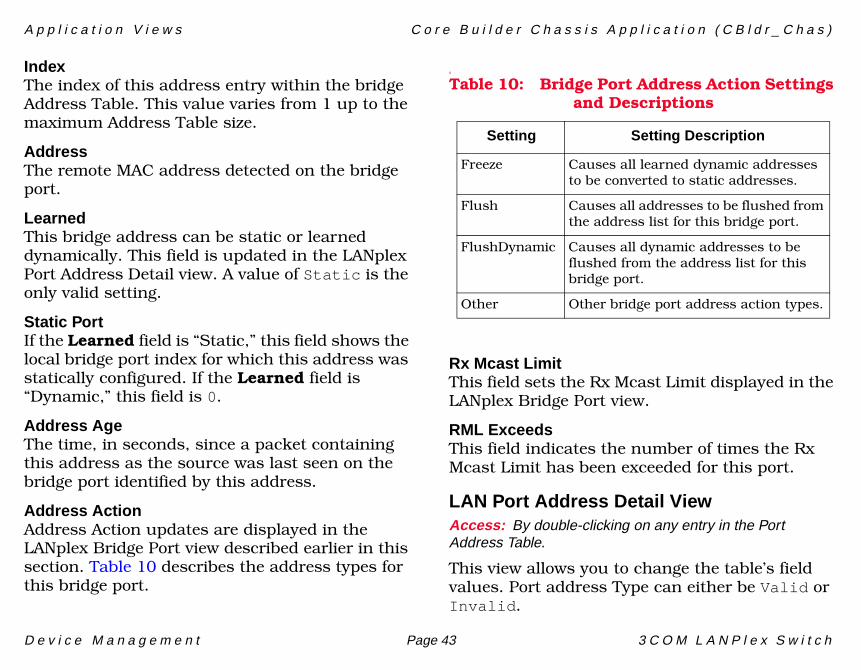
Address ActionAddress Action updates are displayed in the LANplex Bridge Port view described earlier in this section. Table 10 describes the address types for this bridge port.
s
Rx Mcast LimitThis field sets the Rx Mcast Limit displayed in the LANplex Bridge Port view.
RML ExceedsThis field indicates the number of times the Rx Mcast Limit has been exceeded for this port.
LAN Port Address Detail ViewAccess: By double-clicking on any entry in the Port Address Table.
This view allows you to change the table’s field values. Port address Type can either be Valid or Invalid.
Table 10: Bridge Port Address Action Settings and Descriptions
Setting Setting Description
Freeze Causes all learned dynamic addresses to be converted to static addresses.
Flush Causes all addresses to be flushed from the address list for this bridge port.
FlushDynamic Causes all dynamic addresses to be flushed from the address list for this bridge port.
Other Other bridge port address action types.
A p p l i c a t i o n V i e w s C o r e B u i l d e r C h a s s i s A p p l i c a t i o n ( C B l d r _ C h a s )
D e v i c e M a n a g e m e n t Page 44 3 C O M L A N P l e x S w i t c h
LANplex Bridge Port Detail ViewAccess: By double-clicking Frwd Unicast, Frwd Mcast, or Flood Unicast fields in the Bridge Port View.
The Bridge Port Detail view contains three pie charts with the following statistical information for the selected port.
The number of Spanning Tree Frames received is also displayed.
Forwarded UnicastThe number of unicast frames that this port forwarded to a single destination port.
Forwarded MulticastThe number of multicast frames that this port forwarded.
Flooded UnicastThe number of unicast frames that this port flooded to all other ports on this bridge.
Forwarded UnicastThe number of octets displayed in unicast frames that this port forwarded to a single destination port.
Forwarded MulticastThe number of octets in unicast frames that this port forwarded.
Flooded UnicastThe number of octets in unicast frames that this port flooded to all other ports on this bridge.
Rx All Path FilterThe number of frames discarded due to user-defined ‘receive all path’ filters.
Rx BlockedThe number of frames discarded because the receiving port was not in the ‘forwarding’ state.
Rx ErrorThe number of frames discarded because of internal bridge system errors; for example, hardware or software address table discrepancies.
Rx Mcast Path FilterThe number of frames discarded due to user-defined receive multicast path filters.
Invalid AddrThe number of frames discarded with invalid group source addresses or source addresses belonging to this bridge (indicative of network loops).
SecurityThe number of frames discarded with source addresses statically configured on another bridge port. A statically configured station address is not allowed to move or to appear to have moved.
A p p l i c a t i o n V i e w s C o r e B u i l d e r C h a s s i s A p p l i c a t i o n ( C B l d r _ C h a s )
D e v i c e M a n a g e m e n t Page 45 3 C O M L A N P l e x S w i t c h
Dest UnknownThe number of frames discarded because the destination address was unknown.
Same SegmentThe number of frames discarded because the destination address is known on the same network segment as the source address; the frame does not need to be bridged.
Tx All Path FilterThe number of frames discarded due to user-defined ‘transmit all’ path filters.
Tx BlockedThe number of frames discarded; the transmitting port was not in the ‘forwarding’ state.
Tx Mcast Path FilterThe number of frames discarded due to user-defined ‘transmit multicast’ path filters
Tx Mcast ExceedsThe number of frames discarded because the transmit multicast limit was exceeded.
IP Interface Information ViewAccess: From the Chassis Configuration View, select the IP Interface button.
This view contains the Configured IP Interfaces table.
Configured IP Interface TableThis table contains the following information:
StackThe index of the IP stack identified by this entry relative to this agent.
InterfaceThe index of the IP stack identified by this entry relative to this agent.
Interface AddrThe IP address of this entry within the IP stack identified within this entry.
Net MaskThe subnet mask associated with this IP interface. The value of the mask is an IP address with all the network bits set to 1 and all the host bits set to 0.
Default RouteThe IP address of default route of this entry.
Note:Note:
This counter is only valid for backbone ports, and only when the bridge is operating in express mode.
A p p l i c a t i o n V i e w s C o r e B u i l d e r C h a s s i s A p p l i c a t i o n ( C B l d r _ C h a s )
D e v i c e M a n a g e m e n t Page 46 3 C O M L A N P l e x S w i t c h
Proxy ARPThe state of proxy ARP used for this entry. Valid values are: proxyArpDisable, and proxyArpEnable.
ICMP RedirectThe state of ICMP redirect used for this entry.
IP Interface CountThe number of IP interfaces.
Opens the Configured IP Interfaces - Add Entry view, which allows you to add a new entry to the Configured IP Interface Table.
Supported StatusValid system power supply failure types are: AC, Plus5, Plus12, and Over-Temp.
Address ViewAccess: From the Icon Subviews menu for the Lp4xBdgApp Application icon, select Address Table.
This view’s Address table provides access to the Port Address Detail view, described below.
Address TableDouble-clicking on any entry in the Address Table displays the LANplex Port Address Detail view in
which the Learned status of the selected port (Dynamic or Static) and the Type can be updated. Setting the Type to Invalid deletes the entry.
BridgeThe index of the bridge, relative to this agent.
PortThe index of the bridge port within this bridge.
IndexThe index of this address entry within the bridge Address Table. This value varies from 1 up to the maximum Address Table size.
AddressThe remote MAC address detected on the bridge port.
LearnedThis bridge address can be static or learned dynamically. This field is updated in the LANplex Port Address Detail view. A value of Static is the only valid setting when updating this entry; Dynamic can also appear.
Static PortIf the Learned field is “Static,” this field shows the local bridge port index for which this address was statically configured. If the Learned field is “Dynamic,” this field has a value of 0.
Add New Entry
A p p l i c a t i o n V i e w s C o r e B u i l d e r C h a s s i s A p p l i c a t i o n ( C B l d r _ C h a s )
D e v i c e M a n a g e m e n t Page 47 3 C O M L A N P l e x S w i t c h
Address AgeThe time, in seconds, since a packet containing this address as the source existed on the bridge port identified by this address.
Clicking on the Add New Address button displays the LANplex Port Add New Address view. Directions for adding a new address with Instance ID and Remote Address information fields are listed in this view.
Add New Address
D e v i c e M a n a g e m e n t Page 48 3 C O M L A N P l e x S w i t c h
Switch Options
This section provides brief descriptions of the Switch Option views available for the 3COM LANplex switch devices in SPECTRUM.
Access: From the Icon Subviews menu for the Device icon, select Switch Options.
The following options are available from the Switch Options:
• System Information View (Page 35)
• Agent Information View (Page 37)
• Bridge Port Information View (Page 39)
• Ethernet Port Configuration View (Page 25)
• Ethernet Port Performance Summary View (Page 50)
• 3COM VLAN MIB View (Page 33)
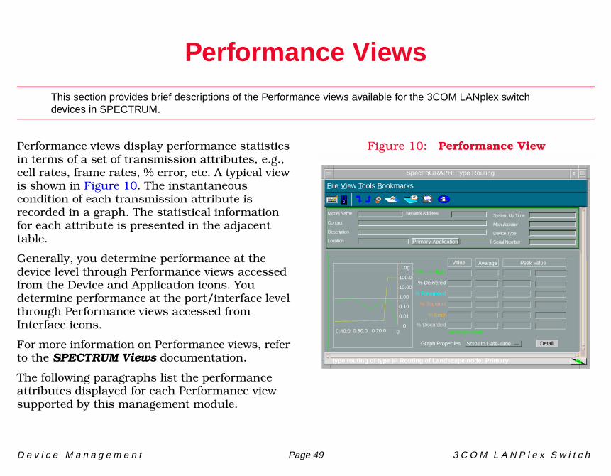
D e v i c e M a n a g e m e n t Page 49 3 C O M L A N P l e x S w i t c h
Performance Views
This section provides brief descriptions of the Performance views available for the 3COM LANplex switch devices in SPECTRUM.
Performance views display performance statistics in terms of a set of transmission attributes, e.g., cell rates, frame rates, % error, etc. A typical view is shown in Figure 10. The instantaneous condition of each transmission attribute is recorded in a graph. The statistical information for each attribute is presented in the adjacent table.
Generally, you determine performance at the device level through Performance views accessed from the Device and Application icons. You determine performance at the port/interface level through Performance views accessed from Interface icons.
For more information on Performance views, refer to the SPECTRUM Views documentation.
The following paragraphs list the performance attributes displayed for each Performance view supported by this management module.
Figure 10: Performance View
SpectroGRAPH: Type Routing
Model Name
Contact
Description
Location
Network Address System Up Time
Manufacturer
Device Type
Serial Number
Log
100.0
10.00
1.00
0.10
0.01
000:40:0 0:30:0 0:20:0
Value Average Peak Value
* Frame Rate
% Delivered
% Forwarded
% Transmit
% Error
DetailGraph Properties Scroll to Date-Time
File View Tools Bookmarks
% Discarded*Frames per second
type routing of type IP Routing of Landscape node: Primary
Primary Application
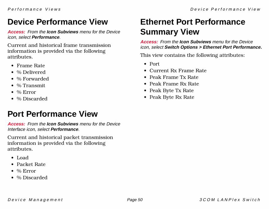
P e r f o r m a n c e V i e w s D e v i c e P e r f o r m a n c e V i e w
D e v i c e M a n a g e m e n t Page 50 3 C O M L A N P l e x S w i t c h
Device Performance ViewAccess: From the Icon Subviews menu for the Device icon, select Performance.
Current and historical frame transmission information is provided via the following attributes.
• Frame Rate• % Delivered• % Forwarded• % Transmit• % Error• % Discarded
Port Performance ViewAccess: From the Icon Subviews menu for the Device Interface icon, select Performance.
Current and historical packet transmission information is provided via the following attributes.
• Load• Packet Rate• % Error• % Discarded
Ethernet Port Performance Summary ViewAccess: From the Icon Subviews menu for the Device icon, select Switch Options > Ethernet Port Performance.
This view contains the following attributes:
• Port• Current Rx Frame Rate• Peak Frame Tx Rate• Peak Frame Rx Rate• Peak Byte Tx Rate• Peak Byte Rx Rate
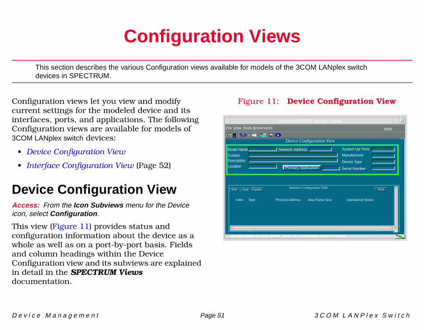
D e v i c e M a n a g e m e n t Page 51 3 C O M L A N P l e x S w i t c h
Configuration Views
This section describes the various Configuration views available for models of the 3COM LANplex switch devices in SPECTRUM.
Configuration views let you view and modify current settings for the modeled device and its interfaces, ports, and applications. The following Configuration views are available for models of 3COM LANplex switch devices:
• Device Configuration View
• Interface Configuration View (Page 52)
Device Configuration ViewAccess: From the Icon Subviews menu for the Device icon, select Configuration.
This view (Figure 11) provides status and configuration information about the device as a whole as well as on a port-by-port basis. Fields and column headings within the Device Configuration view and its subviews are explained in detail in the SPECTRUM Views documentation.
Figure 11: Device Configuration View
SpectroGRAPH: Model Name
Primary Application
System Up Time
Manufacturer
Device Type
Serial Number
Network AddressModel NameContactDescriptionLocation
Device Configuration View
Interface Configuration TableSort Find Update
File View Tools Bookmarks
Index Type Physical Address Max Frame Size Operational Status
Model Name of type JNPR_Mxxx of Landscape node: Primary
Help
C o n f i g u r a t i o n V i e w s I n t e r f a c e C o n f i g u r a t i o n V i e w
D e v i c e M a n a g e m e n t Page 52 3 C O M L A N P l e x S w i t c h
Interface Configuration ViewAccess: From the Icon Subviews menu for an Interface icon in the Device view, select IF Configuration.
This view provides the following information for the selected interface:
Operation StatusThe current operational state of the interface (Up, Down, Unknown, Dormant, Not Present, or Lower Layer Down).
The desired operational state of the interface (up, down, or testing).
Last ChangeThe System UpTime value when the interface entered its current operational state.
IP Address/Network MaskThis window provides a list of the user-defined names and IP addresses for the interface.
Physical AddressThe Ethernet (MAC) address of the interface.
BandwidthThe estimated bandwidth of the interface, measured in bits per second. For interfaces that
do not vary in bandwidth, or no accurate estimate can be made, a nominal bandwidth is provided.
Packet SizeThe largest packet that can be transmitted or received by the port, displayed in octets.
Queue LengthThe length of the outbound packet queue, in packets.
Module Configuration ViewAccess: From the Icon Subviews menu for the Chassis Module icon, select Module Configuration.
This view provides the following information:
Module InstanceThe index of the modular component identified by this entry.
FamilyThe family code for this module.
Generic TypeThe generic type code for this module.
Specific TypeThe specific type code for this module.
Part NumberThe specific part number for this module.
Admin. Status
C o n f i g u r a t i o n V i e w s M o d u l e C o n f i g u r a t i o n V i e w
D e v i c e M a n a g e m e n t Page 53 3 C O M L A N P l e x S w i t c h
Module NumberThe specific part number for this module.
Manufacturing DateThe date that this module was manufactured in the format CCYY-MM-DD. This is the ISO 8601 format.
Module Serial Number3Com serial number.
Top Level Ser NumberTOP level assembly serial number for boards with non-removable daughter cards. Null string for all other board types.
Board RevisionBoard revision code.
Runtime (Hours)A total count of the number of hours this module has been in operation.
ICT Test Status1 equals test passed, or greater than 1 identifies the test number failure (0 or FF indicates field yet not written).
ICT Test RevisionManufacturing ATE test revision number (XX.XX).
System Test Status1 equals test passed, or greater than 1 identifies the test number failure (0 or FF indicates field yet not written).
Functional Test Status1 equals test passed, or greater than 1 identifies the test number failure (0 or FF indicates field yet not written).
Functional Test RevManufacturing functional test revision number (XX.XX).
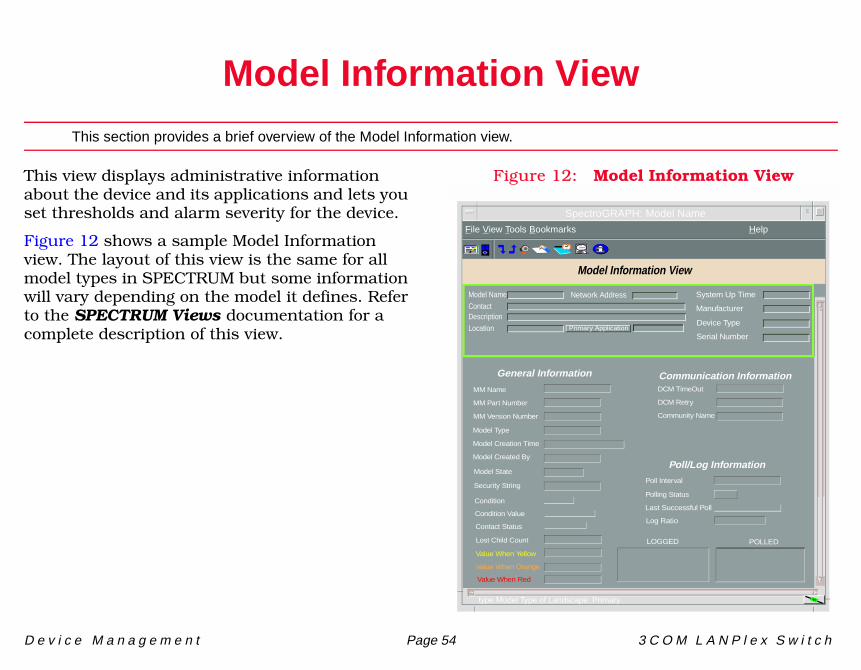
D e v i c e M a n a g e m e n t Page 54 3 C O M L A N P l e x S w i t c h
Model Information View
This section provides a brief overview of the Model Information view.
This view displays administrative information about the device and its applications and lets you set thresholds and alarm severity for the device.
Figure 12 shows a sample Model Information view. The layout of this view is the same for all model types in SPECTRUM but some information will vary depending on the model it defines. Refer to the SPECTRUM Views documentation for a complete description of this view.
Figure 12: Model Information View
Primary Application
System Up Time
Manufacturer
Device Type
Serial Number
Network AddressModel Name
ContactDescription
Location
MM Version Number
MM Name
MM Part Number
General Information
Model Created By
Model Type
Model Creation Time
Model State
Security String
Communication Information
Community Name
DCM TimeOut
DCM Retry
Poll/Log InformationPoll Interval
Polling StatusCondition
Condition Value
Contact Status
Lost Child Count
Value When Yellow
Value When Orange
Value When Red
Last Successful Poll
Log Ratio
LOGGED POLLED
Model Information View
SpectroGRAPH: Model Name
File View Tools Bookmarks Help
type Model Type of Landscape: Primary
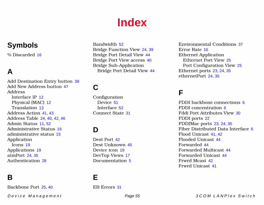
D e v i c e M a n a g e m e n t Page 55 3 C O M L A N P l e x S w i t c h
57
Index
Symbols% Discarded 16
AAdd Destination Entry button 39Add New Address button 47Address
Interface IP 12Physical (MAC) 12Translation 13
Address Action 41, 43Address Table 24, 40, 42, 46Admin Status 11, 52Administrative Status 16administrative status 15Application
Icons 19Applications 19atmPort 24, 35Authentication 28
BBackbone Port 25, 40
Bandwidth 52Bridge Function View 24, 39Bridge Port Detail View 44Bridge Port View access 40Bridge Sub-Application
Bridge Port Detail View 44
CConfiguration
Device 51Interface 52
Connect State 31
DDest Port 42Dest Unknown 45Device icon 19DevTop Views 17Documentation 5
EEB Errors 31
Environmental Conditions 37Error Rate 16Ethernet Application
Ethernet Port View 25Port Configuration View 25
Ethernet ports 23, 24, 35ethernetPort 24, 35
FFDDI backbone connections 6FDDI concentration 6Fddi Port Attributes View 30FDDI ports 22FDDIMac ports 23, 24, 35Fiber Distributed Data Interface 6Flood Unicast 41, 42Flooded Unicast 44Forwarded 44Forwarded Multicast 44Forwarded Unicast 44Frwrd Mcast 42Frwrd Unicast 41
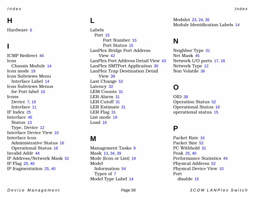
I n d e x I n d e x
D e v i c e M a n a g e m e n t Page 56 3 C O M L A N P l e x S w i t c h
HHardware 6
IICMP Redirect 46Icon
Chassis Module 14Icon mode 19Icon Subviews Menu
Interface Label 14Icon Subviews Menus
for Port label 15Icons
Device 7, 19Interface 11
IF Index 25Interface 45
Status 13Type, Device 12
Interface Device View 10Interface Icon
Administrative Status 16Operational Status 16
Invalid Addr 44IP Address/Network Mask 52IP Flag 25, 40IP fragmentation 25, 40
LLabels
Port 15Port Number 15Port Status 15
LanPlex Bridge Port Address View 42
LanPlex Port Address Detail View 43LanPlex SMTPort Application 30LanPlex Trap Destination Detail
View 39Last Change 52Latency 32LEM Counts 31LER Alarm 31LER Cutoff 31LER Estimate 31LER Flag 31List mode 19Load 16
MManagement Tasks 9Mask 13, 34, 39Mode (Icon or List) 19Model
Information 54Types of 7
Model Type Label 14
Modslot 23, 24, 35Module Identification Labels 14
NNeighbor Type 31Net Mask 45Network I/O ports 17, 18Network Type 12Non Volatile 36
OOID 38Operation Status 52Operational Status 16operational status 15
PPacket Rate 16Packet Size 52PC Withhold 31Peak 25, 40Performance Statistics 49Physical Address 52Physical Device View 10Port
disable 15
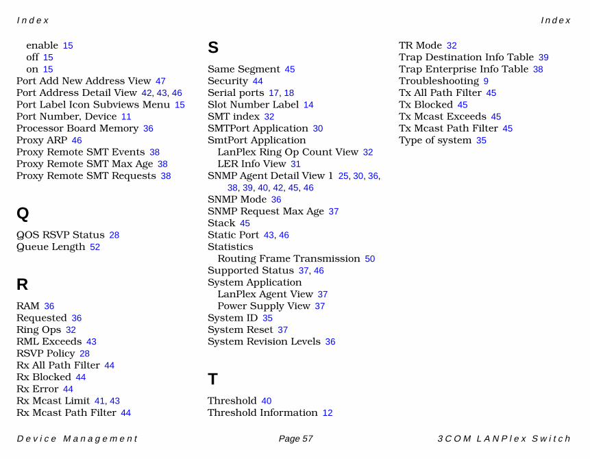
I n d e x I n d e x
D e v i c e M a n a g e m e n t Page 57 3 C O M L A N P l e x S w i t c h
enable 15off 15on 15
Port Add New Address View 47Port Address Detail View 42, 43, 46Port Label Icon Subviews Menu 15Port Number, Device 11Processor Board Memory 36Proxy ARP 46Proxy Remote SMT Events 38Proxy Remote SMT Max Age 38Proxy Remote SMT Requests 38
QQOS RSVP Status 28Queue Length 52
RRAM 36Requested 36Ring Ops 32RML Exceeds 43RSVP Policy 28Rx All Path Filter 44Rx Blocked 44Rx Error 44Rx Mcast Limit 41, 43Rx Mcast Path Filter 44
SSame Segment 45Security 44Serial ports 17, 18Slot Number Label 14SMT index 32SMTPort Application 30SmtPort Application
LanPlex Ring Op Count View 32LER Info View 31
SNMP Agent Detail View 1 25, 30, 36, 38, 39, 40, 42, 45, 46
SNMP Mode 36SNMP Request Max Age 37Stack 45Static Port 43, 46Statistics
Routing Frame Transmission 50Supported Status 37, 46System Application
LanPlex Agent View 37Power Supply View 37
System ID 35System Reset 37System Revision Levels 36
TThreshold 40Threshold Information 12
TR Mode 32Trap Destination Info Table 39Trap Enterprise Info Table 38Troubleshooting 9Tx All Path Filter 45Tx Blocked 45Tx Mcast Exceeds 45Tx Mcast Path Filter 45Type of system 35