Flowmeters - Home - English - Siemens Global Website Flowmeter Application Guidelines 2015 Siemens...
37
Flowmeters
Transcript of Flowmeters - Home - English - Siemens Global Website Flowmeter Application Guidelines 2015 Siemens...

Flowmeters

2
Flowmeter Application Guidelines 2015 Siemens Level and Weighing
Table of Contents
Preface .......................................................................................................................................................... 3
Introduction .................................................................................................................................................. 4
Flowmeter Terminology ................................................................................................................................ 5
Flowmeter Selection ..................................................................................................................................... 6
Flowguide Capacity Charts ............................................................................................................................ 6
Round Flowguide Capacity Chart .............................................................................................................. 7
Rectangular Flowguide Capacity Chart ..................................................................................................... 7
Application and Mounting Guidelines .......................................................................................................... 8
Applications................................................................................................................................................... 9
Screw Conveyor Applications .................................................................................................................... 9
Rotary Feeder Applications ..................................................................................................................... 12
Bucket Elevator Applications .................................................................................................................. 14
Belt Conveyor Applications ..................................................................................................................... 16
Drag Conveyor Applications .................................................................................................................... 18
Aerated Gravity Conveyor Applications .................................................................................................. 20
Vibratory Feeder Applications ................................................................................................................ 22
Knife Gate and Slide Gate Valve Applications ......................................................................................... 23
Chute Applications .................................................................................................................................. 25
Application Considerations ......................................................................................................................... 27
Abrasion .................................................................................................................................................. 27
Temperature ........................................................................................................................................... 29
Adhesion ................................................................................................................................................. 29
Causticity ................................................................................................................................................. 30
Airflow ..................................................................................................................................................... 30
Material Rating Definitions ......................................................................................................................... 31
Rating Chart for Common Materials ........................................................................................................... 32
Product Selection ........................................................................................................................................ 34
Flowmeter ............................................................................................................................................... 34
Notes ........................................................................................................................................................... 35

3
Flowmeter Application Guidelines 2015 Siemens Level and Weighing
Preface The contents of this guide are intended to be used for pre-sales activities when a solids flowmeter solution is being considered. The information required to properly size a flowmeter does not take into consideration many of the other factors that are part of either the environment or the system which can lead to adverse performance if not properly managed or eliminated. Please refer to the appropriate flowmeter operating instructions for full specifications, as well as installation and calibration procedures. Operating Instructions can be downloaded from the Siemens web site at www.siemens.com/weighing. When installed and applied according to the guidelines, flowmeter design and manufacture results in greater accuracy. To help the user maintain the accuracy and performance of the flowmeter, this guideline provides recommendations for the proper application of flowmeters under specific material handling and environmental conditions. The guide is meant to be read chronologically, to both teach and build on the knowledge of how certain aspects of the application can compound with others to create poor performance from the flowmeter.
Note: Other solids flowmeter solutions are available such as Coriolis (measures the change in torque on a motor
driving a van that the material travels through), Flow force (measures the mass and impact velocity of the material at two different points, and integrates them) and Centripetal (measures the centripetal force of material on a curved plate). Users of these mechanical-based solutions can use this guide in the same way as those with impact-based designs can. Non-contact technologies also exist, such as Microwave, Capacitive, and Gamma ray. These technologies do not have the same point of reference as a mechanical-based flowmeter, the basis for this application guideline.
4
Flowmeter Application Guidelines 2015 Siemens Level and Weighing
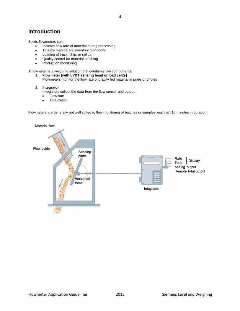
Introduction Solids flowmeters can:
Indicate flow rate of material during processing
Totalize material for inventory monitoring
Loading of truck, ship, or rail car
Quality control for material batching
Production monitoring A flowmeter is a weighing solution that combines two components:
1. Flowmeter (with LVDT sensing head or load cell(s) Flowmeters monitor the flow rate of gravity fed material in pipes or chutes
2. Integrator Integrators collect the data from the flow sensor and output:
Flow rate
Totalization Flowmeters are generally not well suited to flow monitoring of batches or samples less than 10 minutes in duration.

5
Flowmeter Application Guidelines 2015 Siemens Level and Weighing
Flowmeter Terminology
Engineering terms:
Angle of repose The angle of repose is the maximum angle at which an object can rest on an inclined plane without sliding down. It is equal to the arctangent of the coefficient of static friction between the surfaces. When bulk granular materials are poured onto a horizontal surface, a conical pile will form. The internal angle between the surface of the pile and the horizontal surface is known as the angle of repose and is related to the density, surface area, and shapes of the particles, and the coefficient of friction of the material. However the angle of repose is also gravity-dependent. Material with a low angle of repose forms flatter piles than material with a high angle of repose. The angle of repose is the steepest angle of descent or dip relative to the horizontal plane to which a material can be piled without slumping. At this angle, the material on the slope face is on the verge of sliding. The angle of repose can range from 0° to 90°. Smooth, rounded grains cannot be piled as steeply as can rough, interlocking grains. If a small amount of moisture is able to bridge the gaps between particles, electrostatic attraction of the moisture to material surfaces will increase its strength.
Hygroscopic Hygroscopic is the ability of a substance to attract and hold water molecules from the surrounding environment. This is achieved through either absorption or adsorption with the substance becoming physically changed somewhat. This could be by an increase in volume, viscosity or other physical

6
Flowmeter Application Guidelines 2015 Siemens Level and Weighing
characteristic of the substance, as water molecules can become suspended between the substance's molecules in the process.
Flowmeter Selection Choose a flowmeter that best suits your application, based on the following criteria:
Maximum flowrate.
Particle size.
Maximum material temperature.
See page 29 Temperaturefor more information on specifying your flowmeter using temperature.
Bulk density of material.
Use your application criteria to find an appropriate flowmeter. Then, confirm your choice by checking the Material Rating Chart starting on page 32, giving secondary consideration to the following application consequences:
Abrasion Abrasion limits the life of the sensing plate. Also consider wear caused by material direction changes. See page 27 for more information.
Adhesion Material should not stick and build up on the impact area of the sensing plate, as it will cause a calibration shift because of the cushioning effect of the added material. See page 29 for more information.
Causticity Caustic materials can damage flowmeter components. Be aware of caustic vapours as well. See page 30 for more information.
Airflow Inconsistent and unpredictable airflow can cause inaccurate measurement. See page 30 for more information.
Pulsating material flows These are handled well by the LVDT-based models due to the viscous fluid mechanical damper in each sensing head.
Flowguide Capacity Charts The Flowguide Capacity Charts provide guidelines for the selection of the correct flowmeter. To use the graphs, draw a horizontal line from the point on the y-axis that represents the lowest normal bulk density of the weighed material. Similarly, from the x-axis, draw a vertical line from the point that represents the highest normal flowrate. The intersection of these two lines will fall within one of the areas representing a flowguide size. If the point of intersection falls on, or very close to the line dividing two flowguide sizes, select the larger of the two.
Note: The flowguide sizes are based on the sloped flowguides being no more than half full under any condition.
Operating the flowmeters beyond the maximum filling level is not recommended. For vertical flowguides, the maximum design rate should provide one-third to two-thirds filling.

7
Flowmeter Application Guidelines 2015 Siemens Level and Weighing
Round Flowguide Capacity Chart
Rectangular Flowguide Capacity Chart

8
Flowmeter Application Guidelines 2015 Siemens Level and Weighing
Application and Mounting Guidelines In static testing with test weights, the flowmeter performance is repeatable, linear, and reacts minimally to ambient temperature changes. The flowmeters are very accurate instruments in static mode. The flowmeter application will determine how well the flowmeter performs in dynamic mode with material flowing. Follow the guidelines below to reduce the need for modification after the initial installation of your flowmeter.
Use the Flowguide Capacity Chart to ensure you have selected the correct flowmeter model and flowguide size.
Condition the material flow as required to provide repeatable flow patterns for consistent flow from a constant height. The flowmeter’s outputs will only be as repeatable and linear as the flow of the material itself. Linearization of repeatable flow patterns can also be achieved through flowmeter integrator functions.
Ensure that chute-work downstream from the flowmeter will not cause material back up at the sensing plate discharge flange.
The material shape, hardness, and moisture content should remain constant regardless of particle size.
Avoid materials that flow poorly and/or materials that will stick to surfaces of the flowmeter. The material must be self-cleaning in the sensing plate impact area. See Adhesion on page 29 for more information.
Avoid situations that cause air to flow through the flowmeter; this can result in erroneous displays and signals from the flowmeter. Airflow may also be laden with moisture and/or chemical vapors that can cause materials to stick to the impact surfaces of the sensing plate or can cause excess build-up of material on the sensing plate enclosure walls. See Airflow on page 30 for more information.
Protect components of the flowmeter system from damaging, caustic material. Damage can come from the weighed material, as well as from backup air from the downstream process or air flow from the upstream process.
If the material is abrasive, ensure that the sensing plate is properly protected using alumina ceramic tiles, polyurethane, or plasmadized coatings. The transition chutes upstream from the flowmeter’s flowguide, and the flowguide itself may also require protection.
Ensure that the temperature of the material being weighed falls within the flowmeter temperature range. Also ensure that the ambient air temperature is not unreasonably high.
If required, ensure that the flowmeter has the necessary optional equipment for operation within a hazardous environment.
Isolate or remove any influence from vibration
Plan for a method of referencing a known material sample during verification and final calibration of the flowmeter. Two methods are: pre-weighing and running the sample through the flowmeter, or collecting and weighing after the sample has been run through the flowmeter.

9
Flowmeter Application Guidelines 2015 Siemens Level and Weighing
Applications
Screw Conveyor Applications Screw conveyors have a ribbon (or flight) of steel formed and fixed to a shaft. Rotation of the shaft within a tubular structure will convey the material horizontally, or on a slope, from an inlet point to a discharge point. These devices tend to have constant speed with low lineal distance per second values. Screw conveyors provide an inexpensive method of transporting and/or controlling the feed rate of many products. Variable speed screw conveyors are often called screw feeders and typically shear material from a bin or hopper.
Screw Conveyor Application Notes When using a high speed conveyor and/or transporting abrasive materials, a dead box arrangement can limit the impact and wear on the flowguide and sensing plate.
Flighting Normally, the pulsation frequency of material flow from a screw conveyor with standard flighting is acceptable for flowmeters. However, short pitch flighting and double flighting are preferred because they generate a higher pulse frequency and lower magnitude of material pulses.
Constant Speed Conveyors Constant speed conveyors can be applied to maximum speeds of 40 rpm. For abrasive materials, a dead box arrangement is suitable for low and high speed applications.
Variable Speed Conveyors Slower conveyors, with a top speed of up to 20 rpm, can be applied as shown on page 10, although the arrangement shown on page 11 is also applicable. For abrasive materials, a dead box arrangement would be suitable for low and high speed applications.

10
Flowmeter Application Guidelines 2015 Siemens Level and Weighing
Low Speed Screw Conveyors (< 40 rpm)

11
Flowmeter Application Guidelines 2015 Siemens Level and Weighing
High Speed Screw Conveyors (> 40 rpm)

12
Flowmeter Application Guidelines 2015 Siemens Level and Weighing
Rotary Feeder Applications Rotary feeders are generally used for modulating (dosing) material flow or for providing an air seal between processes. The rotary feeder is composed of vanes fixed to a shaft that rotates within a cylindrical structure. The inlet and discharge flanges are normally in-line but can be offset.
In most cases, rotary feeders are designed with minimal clearance between the vanes and the housing, and can be classified as rotary airlock feeders. A reasonably good air seal can be maintained because of the structure and because a pocket can be sealed from both the inlet and the outlet at any given time. This feature allows the device to be applied to situations where the material to be modulated is aerated and free-flowing, as well as in applications where it is desirable to transfer material from one point to another while maintaining an air seal. In applications where there is the possibility of air flow through the flowmeter, a rotary airlock feeder should be considered for installation
above and/or below the solids flowmeter. See Air Flow on page 30 for more information.
Rotary Feeder Application Notes The pockets normally discharge material as a pulse. The LVDT series flowmeters have a viscous fluid damper, which allows them to tolerate the pulse better than a load cell based model. A desirable pulse rate is a minimum of one pulse per second for the LVDT series, and a minimum of two pulses per second for the load cell series. The maximum pulse rate is not a concern because rotary feeders seldom exceed 30 rpm. Worn vanes and housing will contribute to poor modulation control, as well as leakage of both material and air. Rotary feeders often require the vanes and housing to be resurfaced and machined on a regular basis to compensate for wear. Constant speed rotary feeders are generally driven by an AC voltage gear motor/chain drive arrangement. Variable speed rotary feeders tend to be driven by a motor speed controlled DC gear motor/chain drive arrangement, although an AC gear motor can be used with a variable frequency controller.
Constant Speed Rotary Feeders Solids flowmeters can be applied to constant speed rotary feeders, below maximum speeds of 10 rpm, with the rotary feeder having a clockwise rotation. Above that speed, the variation of the trajectory of material from the feeder may cause undesirable flow patterns inside the flowmeter’s flowguide. In such cases, the flowmeter may be best applied with the rotary feeder having a counter-clockwise rotation. For highly abrasive materials, a dead box arrangement would reduce wear to the sensing plate and flowguide.
Variable Speed Rotary Feeders Solids flowmeters can be applied to variable speed rotary feeders with the rotary feeder having a counter-clockwise rotation. If applied with the rotary feeder rotating in the clockwise direction, the variable trajectory of material from the feeder may cause undesirable flow patterns inside the flowmeter’s flowguide, which may cause nonlinearity. For highly abrasive materials, a dead box arrangement would reduce wear to the sensing plate and flowguide.

13
Flowmeter Application Guidelines 2015 Siemens Level and Weighing
Cylindrical Feeders A special version of the rotary air lock feeder has been developed. It uses cylindrical slotting of a solid shaft to create a continuous flow of material through the feeder without creating a pulsating flow. This device is a preferred pre-feeder for solids flowmeters because of the smooth material flow and because a consistent pressure seal can be maintained.

14
Flowmeter Application Guidelines 2015 Siemens Level and Weighing
Bucket Elevator Applications Bucket elevators are conveying devices that elevate material vertically from a lower level to a higher level. Buckets are attached to a chain drive or a reinforced belt. A chain drive is generally slow and material pulsates heavily. A reinforced belt design, sometimes called a leg, is generally used in the grain industry. This belt travels very quickly and creates a high frequency of pulsation. Bucket elevators are constant speed devices that produce constant discharge velocities. Flow pulsation on slower moving elevators will require mechanical damping. Higher speed elevators cause more material abrasion due to higher discharge velocities.
Low Speed Bucket Elevator Knife gate valves can be used effectively to dampen flow pulses. The valve should be mounted at an opening that will provide the most effective damping without causing material plugging and/or backup.
High Speed Bucket Elevator For high discharge velocities, a dead box arrangement can help limit the velocity and reduce wear when required, if the material is abrasive. The use of the gate valve is not required with a high speed bucket elevator.

15
Flowmeter Application Guidelines 2015 Siemens Level and Weighing

16
Flowmeter Application Guidelines 2015 Siemens Level and Weighing
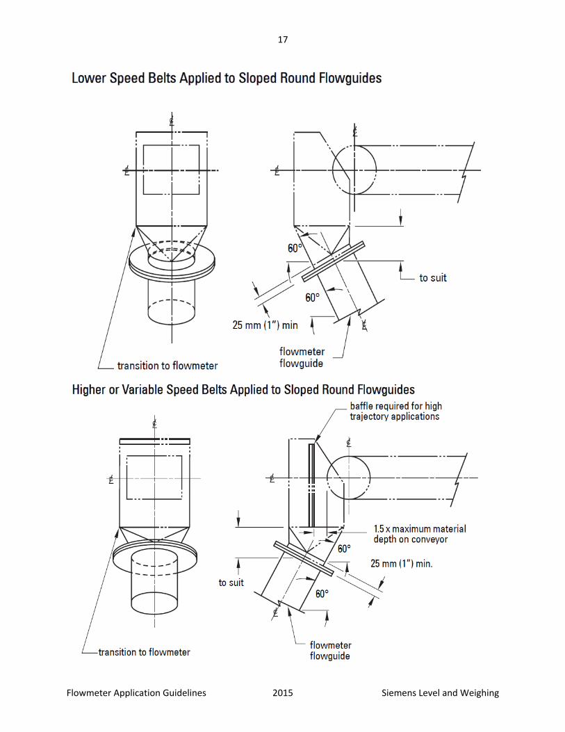
Belt Conveyor Applications Belt conveyors convey dry bulk solids in a horizontal or near-horizontal direction. The belt conveyor has a long moving belt travelling over idlers (rollers). The idlers can be flat (one single horizontal roller) or troughed (combination of three rollers installed at various angles to the horizontal). Belt speeds vary according to the parameters of the conveyor application, from very slow to very fast (refer to the definition of speed below). A belt conveyor that shears material from a bin or hopper at a set belt loading is called a belt feeder. These devices can be constant or variable speed. Solids flowmeters can be used at the discharge of belt conveyors.
Constant Speed Belt Conveyors For slow moving, constant, and variable speed belt conveyors, a simple transition to the flowguide will usually be suitable. A baffle is normally not required. For higher speed belts, a baffle is required.
Variable Speed Belt Conveyors For high velocity, variable speed belts, in applications with little abrasion, a baffle is required. Where abrasion is present, use a dead box arrangement. A dead box arrangement is also suitable for lower speed belts if abrasive materials are being conveyed.
17
Flowmeter Application Guidelines 2015 Siemens Level and Weighing

18
Flowmeter Application Guidelines 2015 Siemens Level and Weighing
Drag Conveyor Applications Drag conveyors move material horizontally along the bottom of an enclosure with chain-driven steel slats. The return strand of the chain rides above the conveying strand. The lower portion of the casing, where the actual conveying takes place, can be tubular or rectangular in design.
Drag conveyors move at a slow, constant speed. These conveyors are wide and have large discharge flanges. Material usually discharges in surges, requiring extensive damping. Modifications can be made to the discharge to reduce the amplitude and increase the duration of the pulses.
If the material being conveyed is abrasive, a dead box will help limit the velocity. See Abrasion on page 27.

19
Flowmeter Application Guidelines 2015 Siemens Level and Weighing

20
Flowmeter Application Guidelines 2015 Siemens Level and Weighing
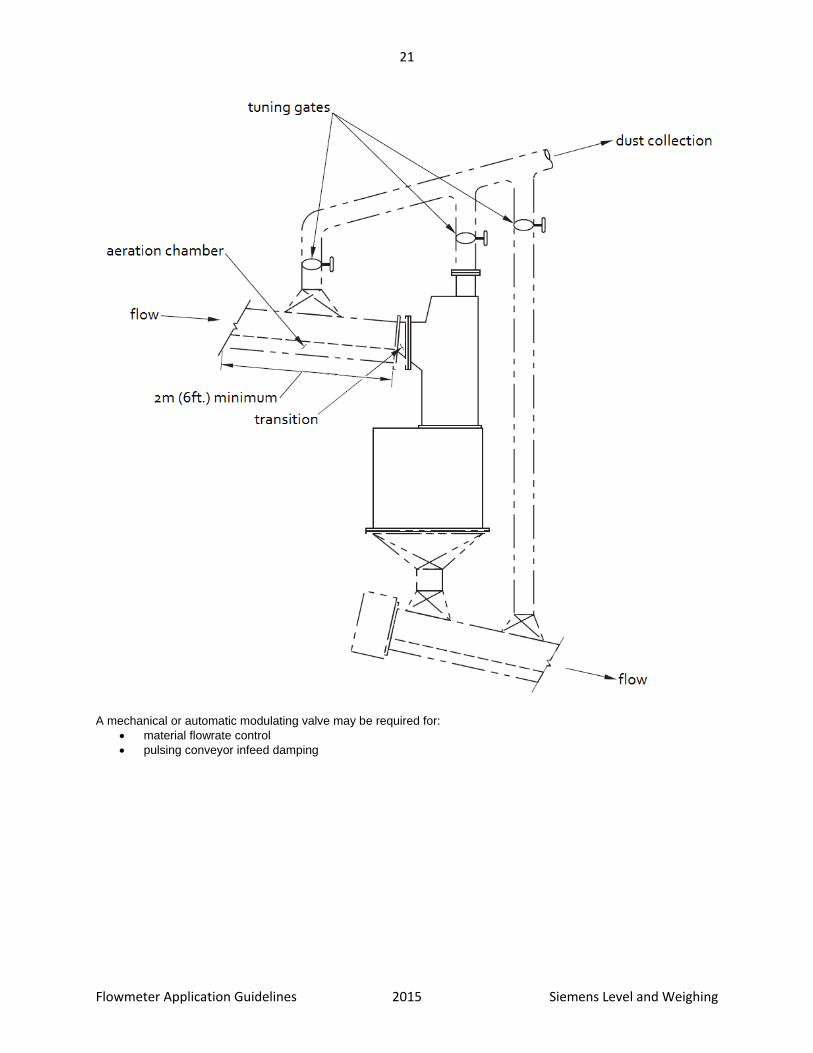
Aerated Gravity Conveyor Applications Aerated gravity conveyors move powdered material in a near horizontal direction. Highly aerated powder enters the conveyor, and the conveyor maintains this aerated condition, and creates a cushion of air above the conveyor’s fabric. This aerated state, along with gravity, allows the material to flow like a fluid. The slope of the conveyor will vary from 5 to 15°, depending on the material being conveyed. The conveyor comprises a rectangular conveying chamber separated from a lower, rectangular aeration chamber by a permeable fabric. Low-pressure, high-volume air is piped into the lower chamber. Air flows through the fabric, aerating the conveyed material and creating a slight cushion of air just above the fabric. The flow of material through an aerated gravity conveyor is usually smooth and consistent. At times, there is some variation in the trajectory of the material from the end of the conveyor.
The biggest concern with an aerated gravity conveyor application is the potential for airflow through the flowmeter. To measure these applications, use special aerated gravity conveyor flowmeters that are designed to allow separate paths for the material being weighed and the airflow.
21
Flowmeter Application Guidelines 2015 Siemens Level and Weighing
A mechanical or automatic modulating valve may be required for:
material flowrate control
pulsing conveyor infeed damping

22
Flowmeter Application Guidelines 2015 Siemens Level and Weighing
Vibratory Feeder Applications The vibratory (or pan) feeder is suitable for use with solids flowmeters. The material is vibrated down a slightly sloped trough, or pan, by a mechanical oscillating drive, making the material flow even and consistent. The feeders can feed at a constant vibration rate, which can be varied by modulating the amplitude of the vibrations to create a variable vibration rate.
When using a constant vibration feeder, the arrangement shown on page 27 is suitable. The flowmeter can also be rotated 180 degrees. In either case, measuring highly abrasive material requires the use of a wear liner or dead box
in the transition chute. See Abrasion on page 27.

23
Flowmeter Application Guidelines 2015 Siemens Level and Weighing
Knife Gate and Slide Gate Valve Applications A knife gate valve has a semi-circular gate sliding inside a circular body. This valve creates a circular aperture when open, while acting as a seal when closed. Knife gate valves are very common in piping systems for fluid flow, but are also used for control of powdered, dry bulk solids. A slide gate valve is the rectangular version of the knife gate valve. It is traditionally used for granular, dry bulk solids and does not use the sealing function that is required for fluids and fine powders. Both devices modulate flow in control systems, and provide on/off control. For modulation applications, the gate and seat should be designed so the opening and closing of the gate maintains a linear opening.
Positioning and Mounting When used with solids flowmeters, knife gate and slide gate valves are usually positioned at the bottom of bins and silos. The slide gate valve is relatively problem-free because the materials being handled are usually free-flowing and granular. In an on/off situation, both valve types should have the opening size fixed and limited so the flow levels do not exceed the capability of the flowmeter and so the flow level remains consistent. Bin aeration and minimum bin levels should be consistently maintained. If the head of the material in the bin becomes a determining factor of flowrate, a special transition chute between the gate valve and the flowmeter may be required to eliminate changing material velocities.
Flow Considerations Normally, material flow problems only occur when the bin level drops below a certain point, or flow conditions within the bin change suddenly, or if the bin runs empty (the flowmeter then receives material from the process without it coming to rest within the bin).

24
Flowmeter Application Guidelines 2015 Siemens Level and Weighing
When measuring granular material using a knife gate valve, a decrease in bin level to low levels or an empty bin can also cause problems. Also, when the knife gate valve is used with powders, inconsistent flows from the bin due to the lack of, or the excess of, flow assistance can cause measuring problems. Flow assistance is usually aeration or vibration to assist the material flow from the bin or hopper.

25
Flowmeter Application Guidelines 2015 Siemens Level and Weighing
Chute Applications
Short Fall Chutes A short fall chute from a prefeeding device or a bin requires minimal monitoring unless the material has exceptionally poor flow characteristics, is abrasive, or the change in level in the bin would cause different discharge velocities.
In general, to ensure a smooth, repeatable flow of material to the flowguide and then to the sensing plate, create a straight run of chute work immediately before the flowguide that is concentric with and at the same angle as the

26
Flowmeter Application Guidelines 2015 Siemens Level and Weighing
flowguide. The material can collect and form a consistent and repeatable flow pattern before entering the flowguide. This is especially important when the chute has a second angle. If the material velocity feeding the flowmeter varies, a dog-leg chute will improve repeatability and linearity.
For highly abrasive material, use a dead box to protect the chute from wear. The dead box may also be used when the material bounces on impact. Allowing the material to pile in the dead box will cushion the impact and allow the
material to quickly establish a desirable flow pattern. See Abrasion on page 27 for more techniques for measuring abrasive material.
Long Fall Chutes A long fall chute from a prefeeding device or bin can create high-impact forces on the flowmeter’s sensing plate. Excessive impact may cause higher than normal abrasion and may limit the range of the flowmeters due to excess movement of the sensing plate within the impact style flowmeters. A chute with the same slope as the flowmeter’s flowguide will not usually need any special modifications before the material enters the flowmeter. However, chutes with slopes different than the flowguide require special attention.

27
Flowmeter Application Guidelines 2015 Siemens Level and Weighing
Higher Sloped Chutes If a chute is 70 to 90° from horizontal, a dead box is often required to limit impact forces and establish repeatable impact points on the sensing plate surface. To limit material velocity, consider a chute that conditions material flow twice, similar to a dog-leg chute.
Lower Sloped Chutes Chutes below 70° from horizontal could be handled with a sloped flowguide to match the chute angle. However, a special sensing plate angle is required as well. Generally, it is preferable to modify the chute work to suit the flowmeter instead of modifying the flowmeter to suit the chutework. If the chute slope is up to 10° greater than the slope of the flowguide, it is necessary to install a short section of chute, with the same slope as the flowguide, immediately before the flowguide. As well, this arrangement will be required if the chute also has a second angle. If the material is particularly abrasive, consider a dead box arrangement. If the chute slope is less than the flowguide slope, install a short chute with the same slope as the flowguide. This arrangement is also be helpful if the chute has a second angle.
Application Considerations
Abrasion Measuring abrasive products reduces the life of the sensing plate. When material changes direction (in the transition chutes before the flowguide), wear is also a concern. Flowguide wear is less of a concern when the material is sliding and not impacting. With some highly abrasive materials, protection against flowguide wear may also be necessary.
To extend the sensing plate’s life, coat or line the plate with abrasion resistant materials or limit the material velocity as it enters the flowguide. Material velocity is limited by allowing the material to impact the surface of the transition chute before the flowguide or against itself in a dead box. A dead box forms a material pile before entering the flowguide, thus dramatically reducing the material velocity while not damaging the chute walls. This arrangement is not suitable for materials that may deteriorate when piled or for sticky materials that will build continuously.

28
Flowmeter Application Guidelines 2015 Siemens Level and Weighing
Sensing plates can be made of abrasion resistant materials or lined with alumina ceramic tiles, abrasion resistant polyurethane, or plasmadized coatings. For selection of the best sensing plate protection, contact your local Siemens
representative. See the Material Rating Charts on page 32. Heavy Duty SS sensing plates can be made without the use of a liner. With larger products, such as 1/2" rock, it is often best to build a heavy duty stainless steel sensing plate which features a greater metal thickness in the product impact area. With the thicker material, there is less chance of metal fatigue due to particle size. The thicker stainless steel will wear harden under these higher impact conditions, which will provide further abrasion resistance. Plasmadizing is the combination of tungsten carbide and PTFE, which provides good protection from abrasion, while also promoting a slick surface that will limit material build-up. The premise of its abrasion resistance is that the surface of the sensing plate is harder than the material impacting upon it. One of the plasmadize advantages is that, because it is applied as a fine layer, it adds limited weight to the sensing plate, which is important with low flow sized series flowmeters. It can be used on most applications, but is not suggested for large particle sizes, since high impact forces can fatigue the metal that the plasmadizing is applied to and reduce the life span of the sensing plate. Also, some products would be better handled with a more resilient liner. Polyurethane is a very resilient product. Rather than meeting the abrasive product head on, this liner will give a little and absorb some of the impact energy thereby reducing the abrasive effect of the impact. Because it is flexible, it can be glued or riveted to a curved surface. If riveted, it can be easily replaced. Polyurethane is particularly useful for the 8, 10, and 12" round flowguide models, but can add too much weight to the sensing plates of the smaller size units. Larger material sizes can tear the polyurethane and thereby limit its life span. Polyurethane has been used mostly with grains such as wheat, corn and soya. Alumina Ceramic applied as tiles meet the granular, or powdered material head on with the tiles being harder than the product being measured. There is only one thing harder than alumina ceramic and that is diamond. Combined with that hardness and the fact that the tiles are 1/4" thick, an alunima ceramic liner generally has a long life span. This is not suggested for larger product sizes, since the tiles will crack and shatter with sharp impact. Single load cell and low flow rate LVDT flowmeters (<2 t/h) cannot tolerate the extra weight that these tiles add to the sensing plate. There are some temperature limitations with the adhesive used to secure the tiles to the sensing plate surface. This liner has been used with products such as grain and alumina powder. In most cases it will outlast the plasmadized and polyurethane liners.
Recommendation This is meant to be a general guideline and may not be completely accurate for some applications. Product Good --------------------------------------->Better Fine Powders Plasmadized Alumina Ceramic Small Granules (-3 mm) Plasmadized Polyurethane Alumina Ceramic, Large Granules (-6 mm) Alumina Ceramic Polyurethane Larger Granules (-13 mm) Polyurethane Heavy Duty SS Very Large Granules (-25 mm) Heavy Duty SS Heavy Duty SS & Polyurethane

29
Flowmeter Application Guidelines 2015 Siemens Level and Weighing
Temperature Flowmeters can accommodate a wide range of product temperatures.
Internally mounted load cell models These designs are mostly limited by temperature because the sensing element (load cell) is integrated as a part of the process. The ambient or product temperature should not exceed the load cell’s compensated temperature of 65
C. However, the load cell can function, on a temporary basis, up to 85 C. The load cell is temperature compensated
to a minimum temperature of -10 C. Operation below or above the rated compensated temperature limits will cause limited measurement inaccuracies.
Externally mounted LVDT models The LVDT series flowmeters are better suited for higher temperature applications because each model’s sensing mechanics are outside the process. Without special features, both models will easily withstand and perform well with
material temperatures as high as 232 C.
Note: The ambient air temperature surrounding the sensing head should not exceed 50 °C in any application.
The sensing head should not be installed as a side mounted device in applications above 140 C process temperature. Above this temperature, the enclosure supporting the side mount unit would distort due to elongation of the metal within its structure. The base mount version of the sensing head should be used instead; it would be supported separately from the enclosure (and the accompanying chute work) and connected by an isolating flexible gasket. The gasket will allow movement of the chute, caused by temperature expansion and contraction, without detrimental effect on the performance of the sensing head.
Externally mounted load cell models These flowmeters will tolerate higher product temperatures than internally mounted load cell models because the sensing elements (load cells) are isolated from the process. The load cells are isolated from the internal enclosure by a high-temperature rated silicone rubber gasket or other means. Since the load cells are supported by the enclosure
structure, material temperatures beyond 100 C would likely cause structural shifting, thereby causing weighing
errors. The ambient temperature around the load cell should not exceed 50 C.
Adhesion Adhesive materials that adhere to the non-impact surfaces of the flowmeter are a concern when this build-up hampers the movement of the sensing plate. If the flowmeter has been properly leveled, there will be no zero shift due to the added mass. It is vital that material not stick and collect on the impact area of the sensing plate. Material build-up will cause a calibration shift due to the cushioning effect of the added material. Material build-up in the flowguide can also cause calibration shift when the coefficient of friction of the flowguide surface will be changed. Most materials will be self-cleaning on the flowguide surfaces and on the impact area of the sensing plate. Some materials will not be self-cleaning and will require anti-stick coatings in the flowguide and/or on the sensing plate surface. However, some materials simply will not be suitable for weighing with an impact flowmeter due to extreme adhesive qualities. See the
Material Rating Chart on page 33 for information. Sensing plates can be lined with non-stick materials such as PTFE, or plasmadized coatings. For selection of the
best sensing plate protection, contact your local Siemens representative. See the Material Rating Chart on page 33. The standard 2B finish of our sensing plates provides the best all-around surface that will allow self-cleaning in the impact area of the sensing plate, which is the most critical part of the sensing plate's surface. Adhesion problems are

30
Flowmeter Application Guidelines 2015 Siemens Level and Weighing
almost always associated with very fine materials such as flour, starch and icing sugar which have high moisture content. Materials which are larger than powder size tend to be self-cleaning in the area of material impingement. In most cases, PTFE coating of the sensing plate will be useful for an adhesive material, but if the particle size is fine enough to lodge itself in a microscopic pore on the surface of the PTFE, material build up can still be a problem. In this case, a mirror finish sensing plate may be the best solution as it is the less costly resolution. So generally, for an adhesive product, PTFE coating is the first solution unless there is prior knowledge of it not being effective with the material in use.
Causticity Materials that have caustic qualities can damage flowmeter components. Sometimes the material being measured is not caustic itself, but caustic vapors may be present from the processes downstream or upstream from the flowmeter.
Load cell model Steel components can be made of stainless steel when the device is to be used with caustic materials. The load cell, the most critical component, is fabricated from stainless steel. The load cell’s encapsulated strain gauges are protected by a gel compound. Some caustic materials can damage the load cell potting gel and eventually the strain gauges, especially where the material has a high moisture content. When there is concern about the suitability of on a caustic material, contact your local Siemens representative.
LVDT model In applications for caustic material, the gaskets of the flowmeters may require special consideration to prevent chemical reaction between the measured material and the gasket. Epoxy paint and synergistic coatings may be required as protection of the aluminum flowmeters castings. The flowmeter’s flowguide and sensing plate enclosure may require special painting or stainless steel construction. The standard type 304 stainless steel sensing plate should be suitable for most caustic material, but some will require type 316, which has a slightly better overall chemical resistance.
Airflow The effects of air flow through a flowmeter can vary from a light constant flow, which can be dynamically zeroed out by the electronics of the flowmeter system, to an air flow that is inconsistent and unpredictable, rendering the flowmeter inaccurate and unreliable. Checking the position of the flowmeter prior to installation can reduce the chances of air flow problems. Placing the flowmeter in a more suitable location is often the only solution. Sometimes, the use of a rotary airlock feeder as a pre-feed device for the flowmeter and/or a rotary airlock feeder after the flowmeter will be sufficient to isolate the flowmeter from excessive air flow. If the flowmeter is installed and air flow creates measurement inaccuracy, reduce the differential pressure across the flowmeter by diverting the air flow around the flowmeter. When a dust collection system is involved, draw air equally from above and below the flowmeter.

31
Flowmeter Application Guidelines 2015 Siemens Level and Weighing
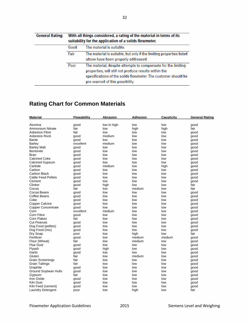
Material Rating Definitions
On page 33, materials that have been successfully weighed with solids flowmeters are listed using the rating criteria defined below.
32
Flowmeter Application Guidelines 2015 Siemens Level and Weighing
Rating Chart for Common Materials
Material Flowability Abrasion Adhesion Causticity General Rating Alumina good low to high low low good Ammonium Nitrate fair low high high fair Asbestos Fibre fair low low low good Asbestos Rock good medium low low good Barite good low low low good Barley excellent medium low low good Barley Malt good low low low good Bentonite good low low low good Bran good low low low good Calcined Coke good low low low good Calcined Gypsum good low low low good Carbide good medium low high good Carbon good low low low good Carbon Black good low low low good Cattle Feed Pellets good low low low good Cement good low low low good Clinker good high low low fair Cocoa fair low medium low fair Cocoa Beans good low low low good Coffee Beans good low low low good Coke good low low low good Copper Calcine good low low low good Copper Concentrate good low low low good Corn excellent medium low low good Corn Fibre good low low low good Corn Flakes fair low low low good Cut Peanuts good low low low good Dog Food (pellets) good low low low good Dog Food (mix) good low low low good Dry Soap poor low high low fair Fertilizer good low medium medium good Flour (Wheat) fair low medium low good Flue Dust good low low low good Flyash good high low low good Garlic good low low low good Gluten fair low medium low good Grain Screenings fair low low low good Grain Tailings fair low low low good Graphite good low low low good Ground Soybean Hulls good low low low good Gypsum fair low low low good Iron Oxide good low low low good Kiln Dust good low low low good Kiln Feed (cement) good low low low good Laundry Detergent poor low high low fair

33
Flowmeter Application Guidelines 2015 Siemens Level and Weighing
Material Flowability Abrasion Adhesion Causticity General Rating Lime (powder) good low low low good Limestone (crushed) good medium low medium good Malt good low low low good Oat Flour good low low low good Oat Groats good low low low good Perlite good low low low good Perlite Ore good high low low fair Petroleum Coke good low low low good Phosphate Rock good low low medium good Plastic Pellets good low low low good Polymer Percol good low low low good Polyethylene Pellets good low low low good Polyethylene Regrind fair low low low good Polystyrene Pellets good low low low good Polymers good low low low good Popping Corn good low low low good Potash good low low medium good Potato Flakes fair low low low good Potato Starch fair low low low good Poultry Feed (mash) good low low low good Precipitator Dust good low low low good Puffed Wheat good low low low good Pulverized Coal good low low low good Resin good low low low good Rice good low low low good Rice Hulls fair low low low good Rye Flour good low low low good Salt good low low medium good Salt Cake poor low medium high fair Sand good medium low low good Sawdust fair low low low good Shorts (wheat) good low low low good Silica Flour good low to med low low good Soap Powder fair low high low fair Soda Ash good low medium medium good Sodium Chloride good low low medium good Sodium Sulphate good low low medium fair Soya Beans good medium low low good Soya Bean Hulls fair low low low good Starch fair low medium low fair Steel Shot good medium low low good Sugar good low medium low good Sunflower Seeds good low low low good Titanium Dioxide good low low low good Unshelled Peanuts good low low low good Uranium Dioxide good low low low good Uranium Trioxide good low low low good Urea fair low high high fair Vermiculite good low low low good Wheat good medium low low good Wheat Fines good low low low good Whole Onions good low low low good Wood Pellets good low low low good Wood Pulp poor low low low fair Zinc Oxide good low low low good

34
Flowmeter Application Guidelines 2015 Siemens Level and Weighing
Product Selection
Flowmeter There are many different styles of flowmeters available such as compact, slanted, and vertical infeeds. Generally there are three drivers to selection of the proper flowmeter:
Application needs Determines the specific selection of models and options. The environment will also play a part; the flowmeter should be stainless in corrosive areas or near sea ports. If the location is considered hazardous, an approved flowmeter will be needed.
Price point Influences the selection of the type of flowmeter. Load cell models by their nature are less expensive, but if the application is not suited to them, they should not be used.
Flowmeter sizing Limitations based on application needs and product features or performance will narrow the selection of the product in most cases. Product size, sensor optimization, and material flow means are all considered when a flowmeter is engineered.

35
Flowmeter Application Guidelines 2015 Siemens Level and Weighing
Notes

36
Flowmeter Application Guidelines 2015 Siemens Level and Weighing

For more information www.siemens.com/weighing