Flow Control For Gigabit Ethernet - IEEE 802 Semiconductor Digital Equipment Corporation (Digital) 2...
31
Digital Semiconductor Digital Semiconductor Digital Equipment Corporation (Digital) 1 Flow Control For Gigabit Ethernet Flow Control For Gigabit Ethernet Moshe De-Leon Digital Equipment Corporation (Digital) IEEE 802.3z Task Force 9-July-1996
Transcript of Flow Control For Gigabit Ethernet - IEEE 802 Semiconductor Digital Equipment Corporation (Digital) 2...
Digital SemiconductorDigital Semiconductor
Digital Equipment Corporation (Digital)
1
Flow Control For Gigabit EthernetFlow Control For Gigabit Ethernet
Moshe De-LeonDigital Equipment Corporation (Digital)
IEEE 802.3z Task Force 9-July-1996
Digital SemiconductorDigital Semiconductor
Digital Equipment Corporation (Digital)
2
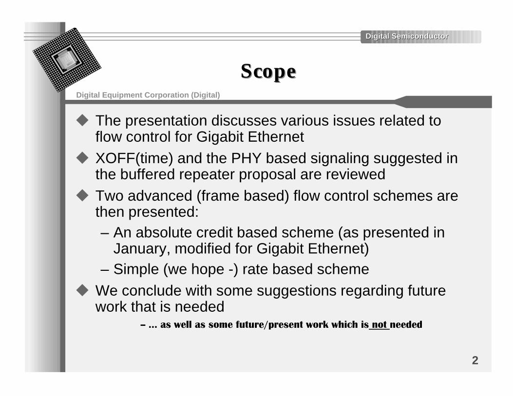
ScopeScope
u The presentation discusses various issues related toflow control for Gigabit Ethernet
u XOFF(time) and the PHY based signaling suggested inthe buffered repeater proposal are reviewed
u Two advanced (frame based) flow control schemes arethen presented:– An absolute credit based scheme (as presented in
January, modified for Gigabit Ethernet)– Simple (we hope -) rate based scheme
u We conclude with some suggestions regarding futurework that is needed
����AS�WELL�AS�SOME�FUTURE�PRESENT�WORK�WHICH�IS�NOT�NEEDED
Digital SemiconductorDigital Semiconductor
Digital Equipment Corporation (Digital)
3
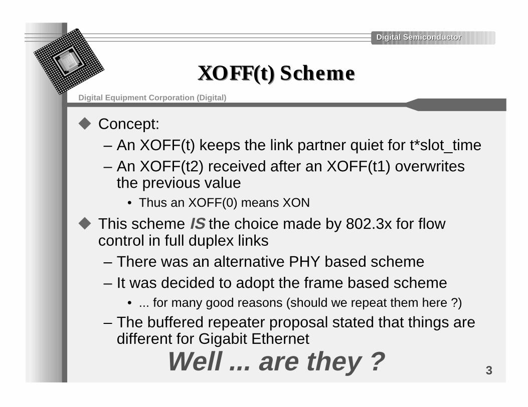
XOFF(t) SchemeXOFF(t) Scheme
u Concept:– An XOFF(t) keeps the link partner quiet for t*slot_time– An XOFF(t2) received after an XOFF(t1) overwrites
the previous value• Thus an XOFF(0) means XON
u This scheme IS the choice made by 802.3x for flowcontrol in full duplex links– There was an alternative PHY based scheme– It was decided to adopt the frame based scheme
• ... for many good reasons (should we repeat them here ?)
– The buffered repeater proposal stated that things aredifferent for Gigabit Ethernet
Well ... are they ?
Digital SemiconductorDigital Semiconductor
Digital Equipment Corporation (Digital)
4
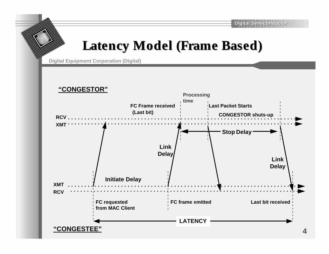
Latency Model (Frame Based)Latency Model (Frame Based)
RCV
XMT
XMT
RCV
“CONGESTOR”
“CONGESTEE”
CONGESTOR shuts-up
FC Frame received
Last bit receivedFC requested from MAC Client
FC frame xmitted
LATENCY
Initiate Delay
LinkDelay
Stop Delay
Last Packet Starts
LinkDelay
(Last bit)
Processing time
Digital SemiconductorDigital Semiconductor
Digital Equipment Corporation (Digital)
5
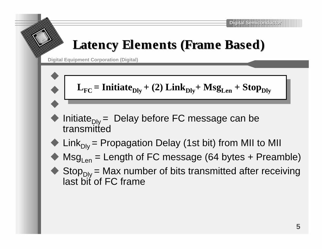
Latency Elements (Frame Based)Latency Elements (Frame Based)
u
u
u
u InitiateDly = Delay before FC message can betransmitted
u LinkDly = Propagation Delay (1st bit) from MII to MIIu MsgLen = Length of FC message (64 bytes + Preamble)u StopDly = Max number of bits transmitted after receiving
last bit of FC frame
LFC = InitiateDly + (2) LinkDly+ MsgLen + StopDly
Digital SemiconductorDigital Semiconductor
Digital Equipment Corporation (Digital)
6
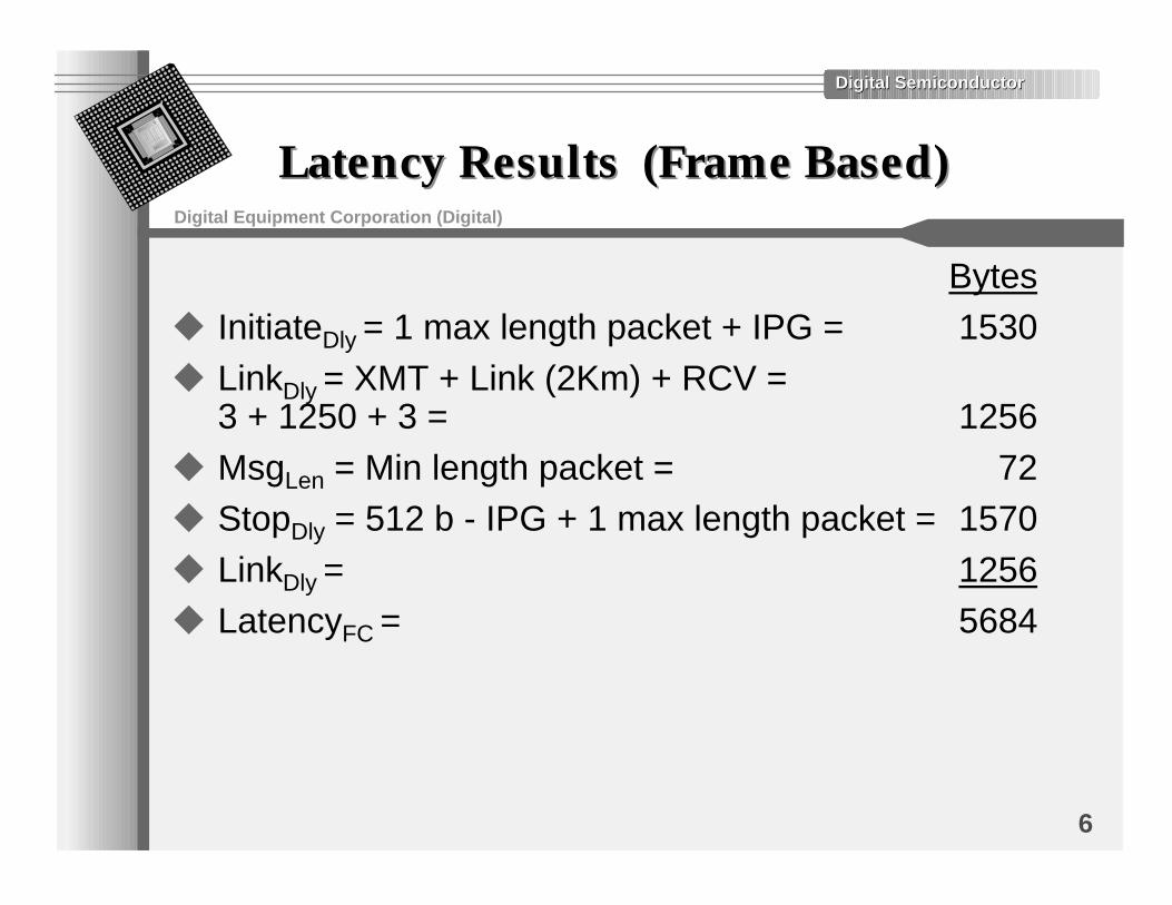
Latency Results (Frame Based)Latency Results (Frame Based)
Bytesu InitiateDly = 1 max length packet + IPG = 1530u LinkDly = XMT + Link (2Km) + RCV =
3 + 1250 + 3 = 1256u MsgLen = Min length packet = 72u StopDly = 512 b - IPG + 1 max length packet = 1570u LinkDly = 1256u LatencyFC = 5684
Digital SemiconductorDigital Semiconductor
Digital Equipment Corporation (Digital)
7
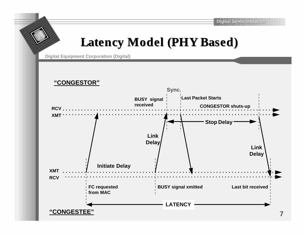
Latency Model (PHY Based)Latency Model (PHY Based)
RCV
XMT
XMT
RCV
“CONGESTOR”
“CONGESTEE”
CONGESTOR shuts-up
Last bit receivedFC requested from MAC
BUSY signal xmitted
LATENCY
Initiate Delay
LinkDelay
Stop Delay
Last Packet Starts
LinkDelay
BUSY signalreceived
Sync.
Digital SemiconductorDigital Semiconductor
Digital Equipment Corporation (Digital)
8
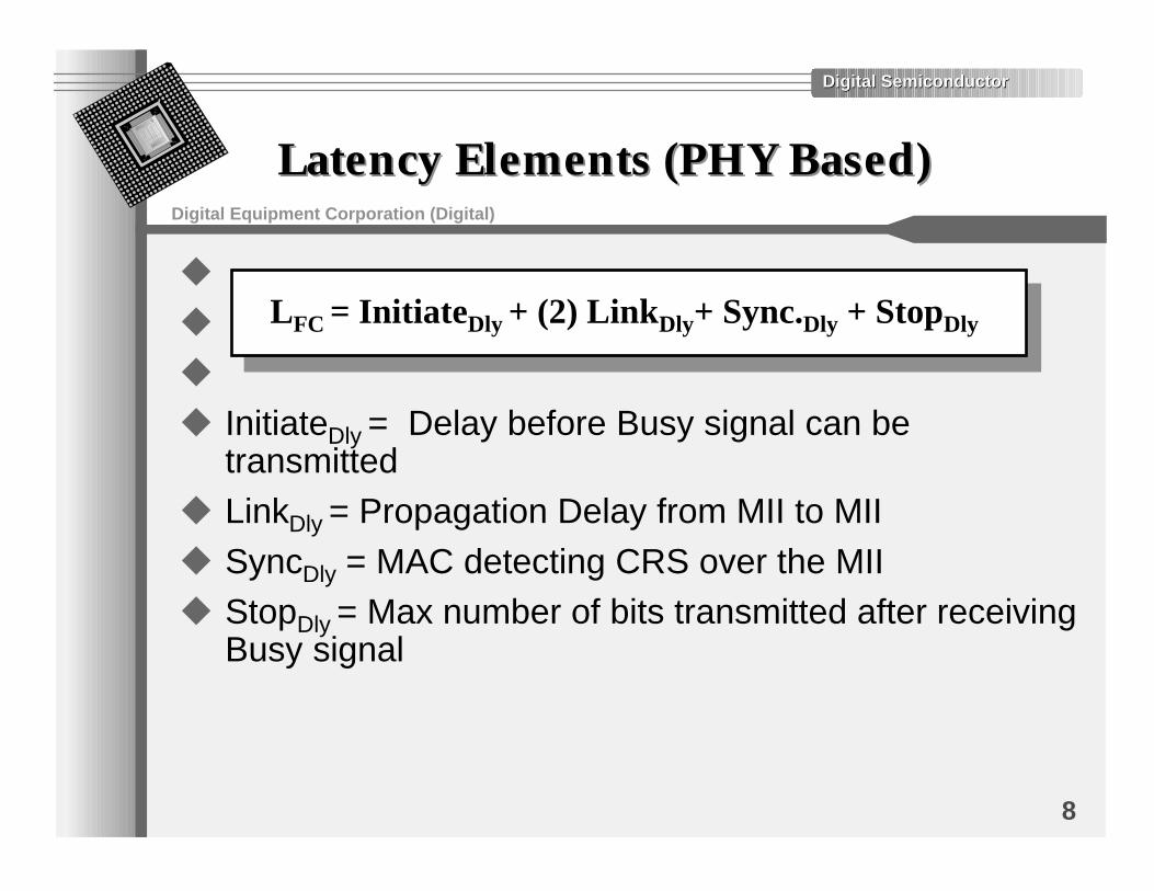
Latency Elements (PHY Based)Latency Elements (PHY Based)
u
u
u
u InitiateDly = Delay before Busy signal can betransmitted
u LinkDly = Propagation Delay from MII to MIIu SyncDly = MAC detecting CRS over the MIIu StopDly = Max number of bits transmitted after receiving
Busy signal
LFC = InitiateDly + (2) LinkDly+ Sync.Dly + StopDly
Digital SemiconductorDigital Semiconductor
Digital Equipment Corporation (Digital)
9
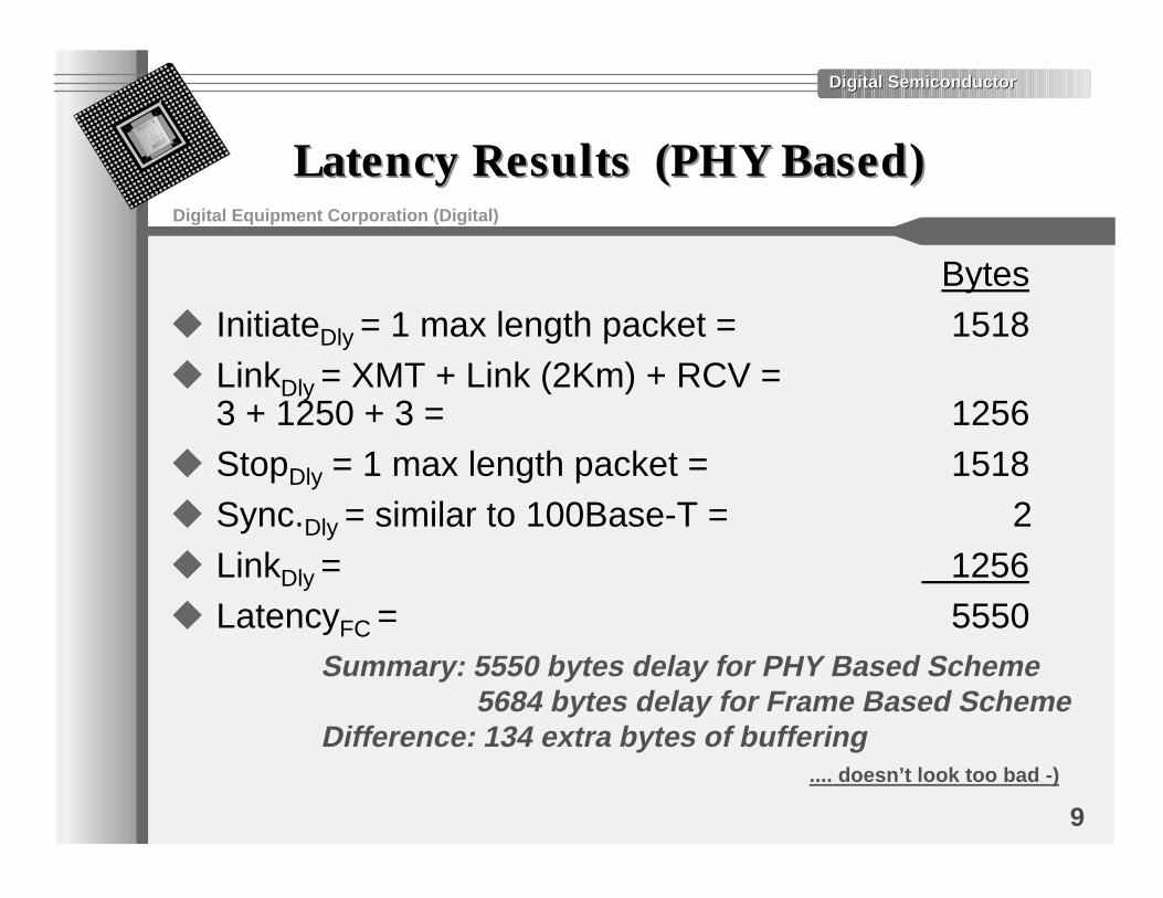
Latency Results (PHY Based)Latency Results (PHY Based)
Bytesu InitiateDly = 1 max length packet = 1518u LinkDly = XMT + Link (2Km) + RCV =
3 + 1250 + 3 = 1256u StopDly = 1 max length packet = 1518u Sync.Dly = similar to 100Base-T = 2u LinkDly = 1256u LatencyFC = 5550
Summary: 5550 bytes delay for PHY Based Scheme 5684 bytes delay for Frame Based SchemeDifference: 134 extra bytes of buffering .... doesn’t look too bad -)
Digital SemiconductorDigital Semiconductor
Digital Equipment Corporation (Digital)
10
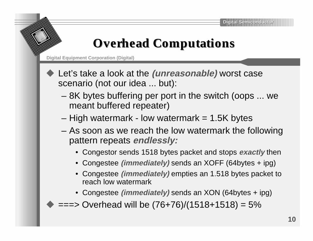
Overhead ComputationsOverhead Computations
u Let’s take a look at the (unreasonable) worst casescenario (not our idea ... but):– 8K bytes buffering per port in the switch (oops ... we
meant buffered repeater)– High watermark - low watermark = 1.5K bytes– As soon as we reach the low watermark the following
pattern repeats endlessly:• Congestor sends 1518 bytes packet and stops exactly then• Congestee (immediately) sends an XOFF (64bytes + ipg)• Congestee (immediately) empties an 1.518 bytes packet to
reach low watermark• Congestee (immediately) sends an XON (64bytes + ipg)
u ===> Overhead will be (76+76)/(1518+1518) = 5%
Digital SemiconductorDigital Semiconductor
Digital Equipment Corporation (Digital)
11
Overhead ConclusionOverhead Conclusion
u This (unreasonably) assumes a worst case conditionfor a long period of time– Congestor pattern is not likely to repeat too often– Congestee is extremely unlucky– All these (immediately)’s are not too likely to ever
happenu It ignores the t in the XOFF(t) commandu Given a more practical buffer size of 16K bytes per port
(not too expensive for Gigabit ...):– High watermark - low water mark = 9.5K bytes– Overhead (yes, in this ... scenario) is less than 0.8%
u ===> In ALL practical scenarios - overhead isnegligible
Digital SemiconductorDigital Semiconductor
Digital Equipment Corporation (Digital)
12
The Issue of RobustnessThe Issue of Robustness
u Given a bit error rate of 10**(-12)– The chances of a corrupted XOFF(t) frame are:
• 1 - ((1- (10**(-12)))**512) = 0.000000000512
• One way to look at it - one flow control frame out of every1953125000 flow control frames is corrupted
• Assuming the worst case scenario of the overheadcomputation above, an XOFF(t) flow control frame istransmitted every 1518+1518+76 +76 bytes or every 25504bits ... or 39210 frames per secondÐ �����WE�WILL�HAVE�AN�8/&&�DROPPED�EVERY�����������������SECONDS���������SECONDS�������MINUTES���EVERY�^���HOURS
Ð 4HIS�MEANS�������TO���PACKETS�ARE�DROPPED��UNTIL�THE�ÕCONGESTEEÖSENDS�ANOTHER�8/&&
Р-ANY�MORE�$!4!�FRAMES�WILL�BE�LOST�SIMPLY�DUE�TO�����BIT�ERROR�RATE
We “think” we can live with 2-5 packets being dropped every 14 hours in this unreasonable worst case scenario -)
Digital SemiconductorDigital Semiconductor
Digital Equipment Corporation (Digital)
13
Other ObservationsOther Observations
u Assuming PHY is full duplex - why stop when receivingor for that matter - why look at CRS at all ?
• ===> The suggested buffered repeater scheme introduces(unnecessary) 50% overhead
• ... But if this is full duplex, then this is no longer a (buffered)repeater ( I guess...)
u And there are “other” issues:• Why have three types of MAC ?• Why have PHY and Frame based flow control ? One of our
(802.3x) goals was to have one flow control for alltechnologies and all speeds
• Why specify the architecture and/or behavior of a switch ?• Why does 802.3 need to discuss products ?• Why make the PHY more complex (even slightly) ?• What does this “thing” buy us if “it does not replace
traditional CSMA/CD ?”
Digital SemiconductorDigital Semiconductor
Digital Equipment Corporation (Digital)
14
On Idle/Busy PHY SignalsOn Idle/Busy PHY Signals
u It can be claimed about Idle/Busy:– “Let’s just define these, maybe someone will use
them some day”u Problem:
– As soon as we define them we have to specify theirsemantics
– As soon as we specify their semantics we have a newflow control scheme
Do we really need two flow control schemes for Ethernet ? When the benefit is so small (i.e. less than 134 bytes of buffering)
Digital SemiconductorDigital Semiconductor
Digital Equipment Corporation (Digital)
15
An Alternative Buffered RepeaterAn Alternative Buffered RepeaterProposalProposal
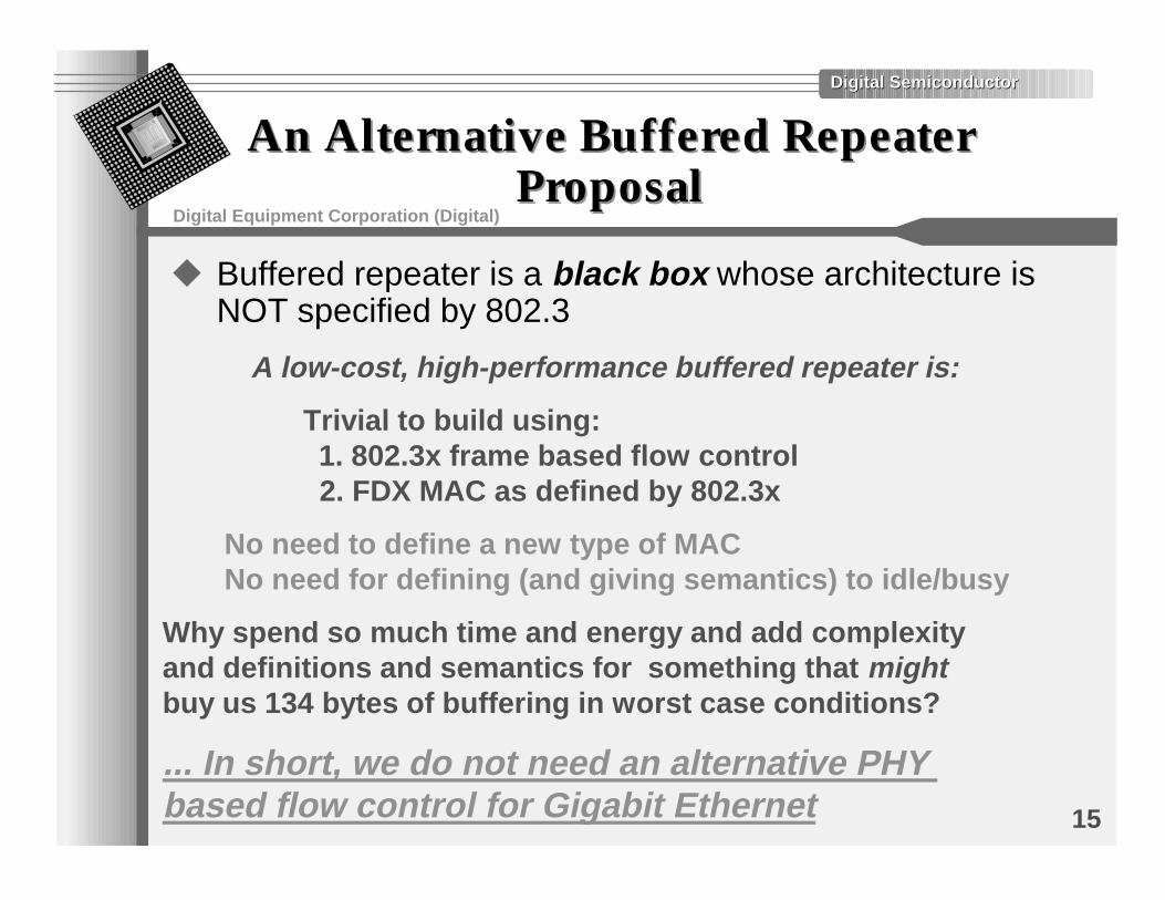
u Buffered repeater is a black box whose architecture isNOT specified by 802.3
A low-cost, high-performance buffered repeater is:
Trivial to build using: 1. 802.3x frame based flow control 2. FDX MAC as defined by 802.3x
Why spend so much time and energy and add complexityand definitions and semantics for something that might buy us 134 bytes of buffering in worst case conditions?
No need to define a new type of MACNo need for defining (and giving semantics) to idle/busy
... In short, we do not need an alternative PHY based flow control for Gigabit Ethernet
Digital SemiconductorDigital Semiconductor
Digital Equipment Corporation (Digital)
16
Buffered Repeater ConclusionBuffered Repeater Conclusion
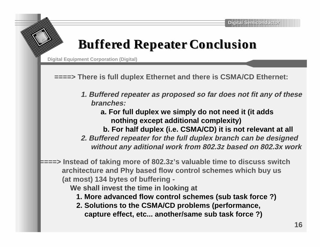
====> Instead of taking more of 802.3z’s valuable time to discuss switch architecture and Phy based flow control schemes which buy us (at most) 134 bytes of buffering - We shall invest the time in looking at 1. More advanced flow control schemes (sub task force ?) 2. Solutions to the CSMA/CD problems (performance, capture effect, etc... another/same sub task force ?)
====> There is full duplex Ethernet and there is CSMA/CD Ethernet: 1. Buffered repeater as proposed so far does not fit any of these branches: a. For full duplex we simply do not need it (it adds nothing except additional complexity) b. For half duplex (i.e. CSMA/CD) it is not relevant at all 2. Buffered repeater for the full duplex branch can be designed without any aditional work from 802.3z based on 802.3x work
Digital SemiconductorDigital Semiconductor
Digital Equipment Corporation (Digital)
17
Credit Based Flow Control ConceptCredit Based Flow Control Concept
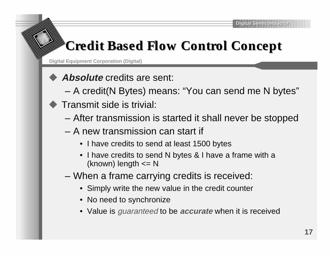
u Absolute credits are sent:– A credit(N Bytes) means: “You can send me N bytes”
u Transmit side is trivial:– After transmission is started it shall never be stopped– A new transmission can start if
• I have credits to send at least 1500 bytes• I have credits to send N bytes & I have a frame with a
(known) length <= N
– When a frame carrying credits is received:• Simply write the new value in the credit counter• No need to synchronize
• Value is guaranteed to be accurate when it is received
Digital SemiconductorDigital Semiconductor
Digital Equipment Corporation (Digital)
18
Credit Based Flow Control ConceptCredit Based Flow Control Concept(cont.)(cont.)
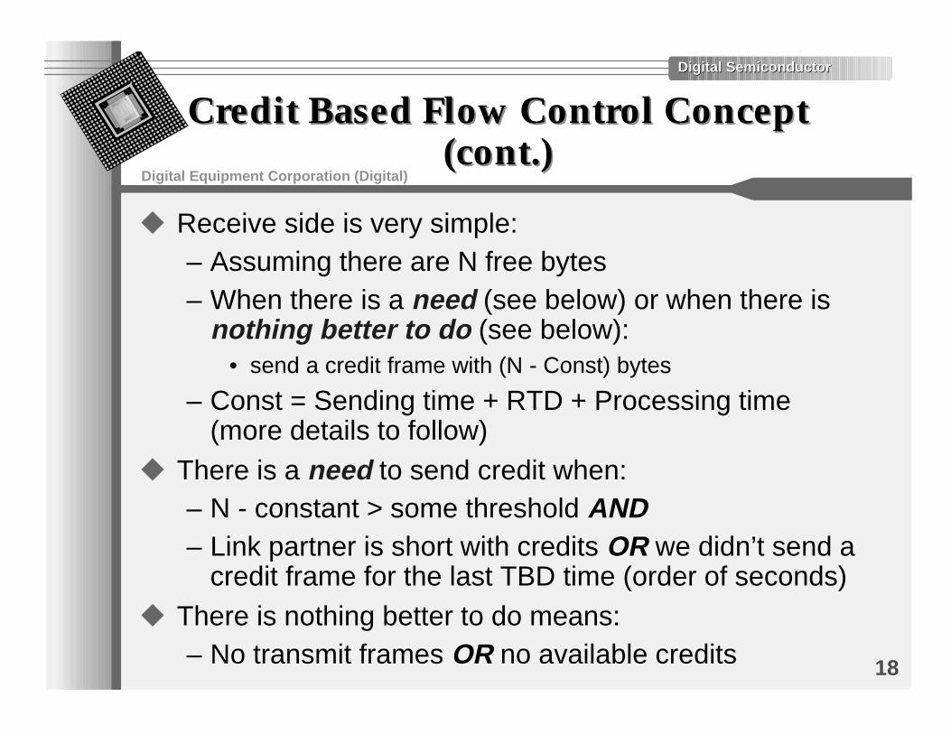
u Receive side is very simple:– Assuming there are N free bytes– When there is a need (see below) or when there is
nothing better to do (see below):• send a credit frame with (N - Const) bytes
– Const = Sending time + RTD + Processing time(more details to follow)
u There is a need to send credit when:– N - constant > some threshold AND– Link partner is short with credits OR we didn’t send a
credit frame for the last TBD time (order of seconds)u There is nothing better to do means:
– No transmit frames OR no available credits
Digital SemiconductorDigital Semiconductor
Digital Equipment Corporation (Digital)
19
Credit Based Flow Control -Credit Based Flow Control -Constant Part CalculationsConstant Part Calculations
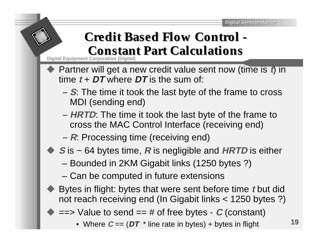
u Partner will get a new credit value sent now (time is t) intime t + DT where DT is the sum of:– S: The time it took the last byte of the frame to cross
MDI (sending end)– HRTD: The time it took the last byte of the frame to
cross the MAC Control Interface (receiving end)– R: Processing time (receiving end)
u S is ~ 64 bytes time, R is negligible and HRTD is either– Bounded in 2KM Gigabit links (1250 bytes ?)– Can be computed in future extensions
u Bytes in flight: bytes that were sent before time t but didnot reach receiving end (In Gigabit links < 1250 bytes ?)
u ==> Value to send == # of free bytes - C (constant)• Where C == (DT * line rate in bytes) + bytes in flight
Digital SemiconductorDigital Semiconductor
Digital Equipment Corporation (Digital)
20
Credit Based Flow Control -Credit Based Flow Control -Intermediate SummaryIntermediate Summary
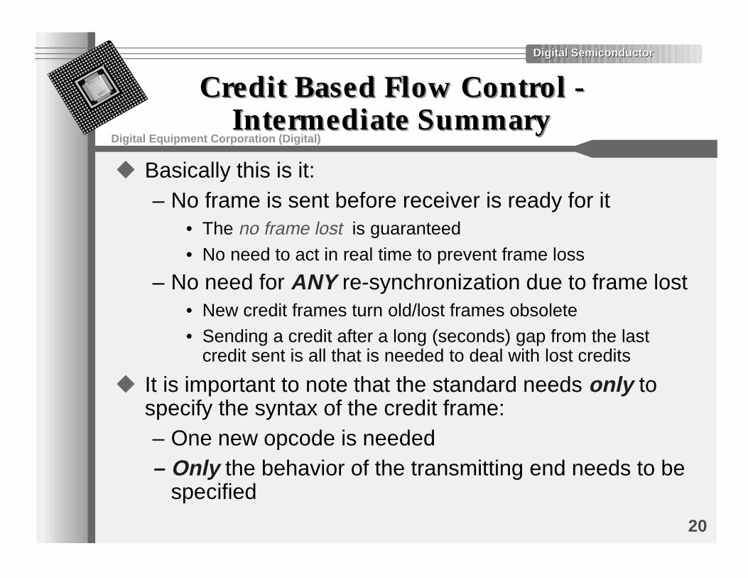
u Basically this is it:– No frame is sent before receiver is ready for it
• The no frame lost is guaranteed
• No need to act in real time to prevent frame loss
– No need for ANY re-synchronization due to frame lost• New credit frames turn old/lost frames obsolete• Sending a credit after a long (seconds) gap from the last
credit sent is all that is needed to deal with lost credits
u It is important to note that the standard needs only tospecify the syntax of the credit frame:– One new opcode is needed– Only the behavior of the transmitting end needs to be
specified
Digital SemiconductorDigital Semiconductor
Digital Equipment Corporation (Digital)
21
Credit Based Flow Control -Credit Based Flow Control -Pseudo CodePseudo Code
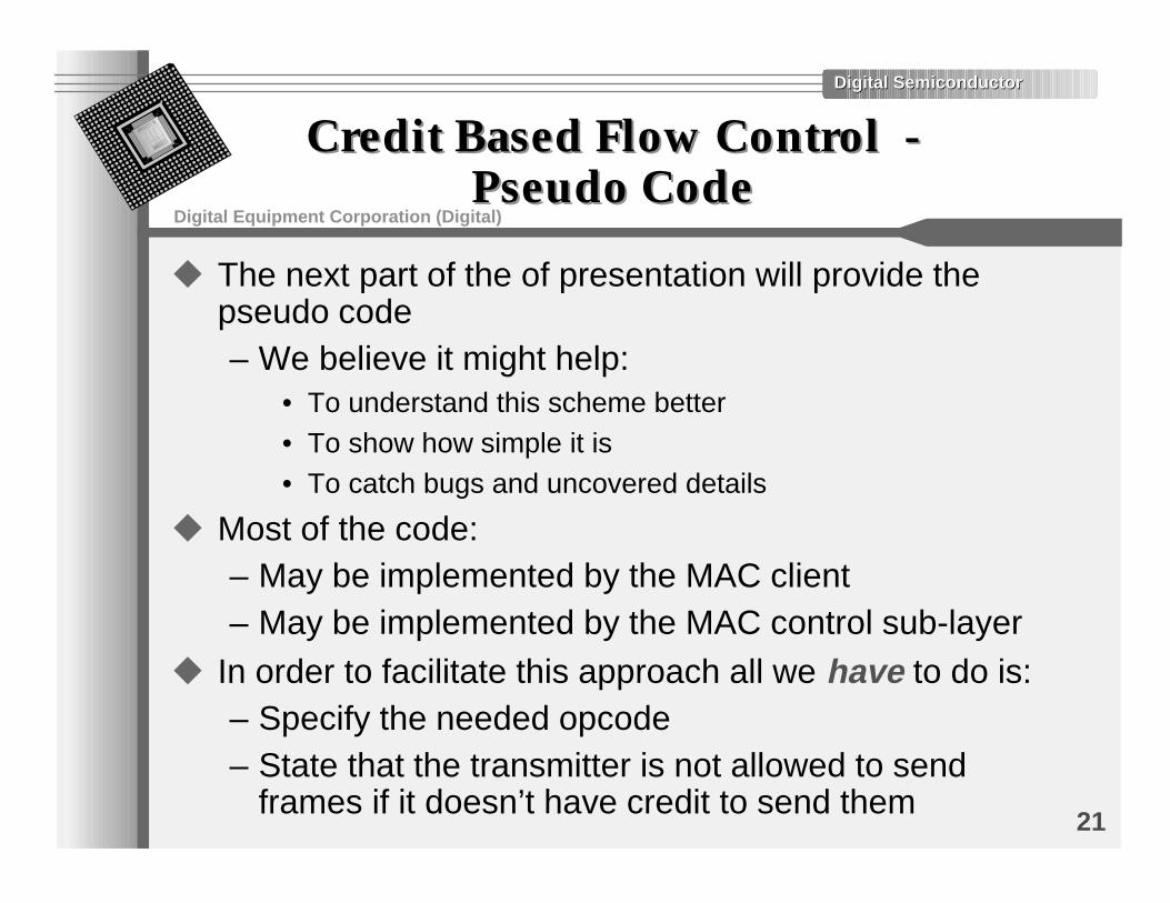
u The next part of the of presentation will provide thepseudo code– We believe it might help:
• To understand this scheme better• To show how simple it is• To catch bugs and uncovered details
u Most of the code:– May be implemented by the MAC client– May be implemented by the MAC control sub-layer
u In order to facilitate this approach all we have to do is:– Specify the needed opcode– State that the transmitter is not allowed to send
frames if it doesn’t have credit to send them
Digital SemiconductorDigital Semiconductor
Digital Equipment Corporation (Digital)
22
Credit Credit BBased Flow Control -ased Flow Control -ConstantsConstants
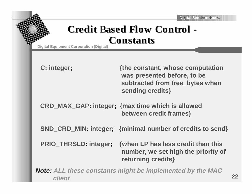
C: integer; {the constant, whose computation was presented before, to be subtracted from free_bytes when sending credits} CRD_MAX_GAP: integer; {max time which is allowed between credit frames} SND_CRD_MIN: integer; {minimal number of credits to send} PRIO_THRSLD: integer; {when LP has less credit than this number, we set high the priority of returning credits}
Note: ALL these constants might be implemented by the MAC client
Digital SemiconductorDigital Semiconductor
Digital Equipment Corporation (Digital)
23
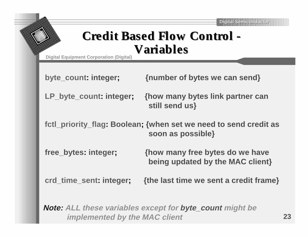
Credit Based Flow Control -Credit Based Flow Control -VariablesVariables
byte_count: integer; {number of bytes we can send}
LP_byte_count: integer; {how many bytes link partner can still send us}
fctl_priority_flag: Boolean; {when set we need to send credit as soon as possible}
free_bytes: integer; {how many free bytes do we have being updated by the MAC client}
crd_time_sent: integer; {the last time we sent a credit frame}
Note: ALL these variables except for byte_count might be implemented by the MAC client
Digital SemiconductorDigital Semiconductor
Digital Equipment Corporation (Digital)
24
Credit Based Flow Control -Credit Based Flow Control -Transmitter ProcessTransmitter Process
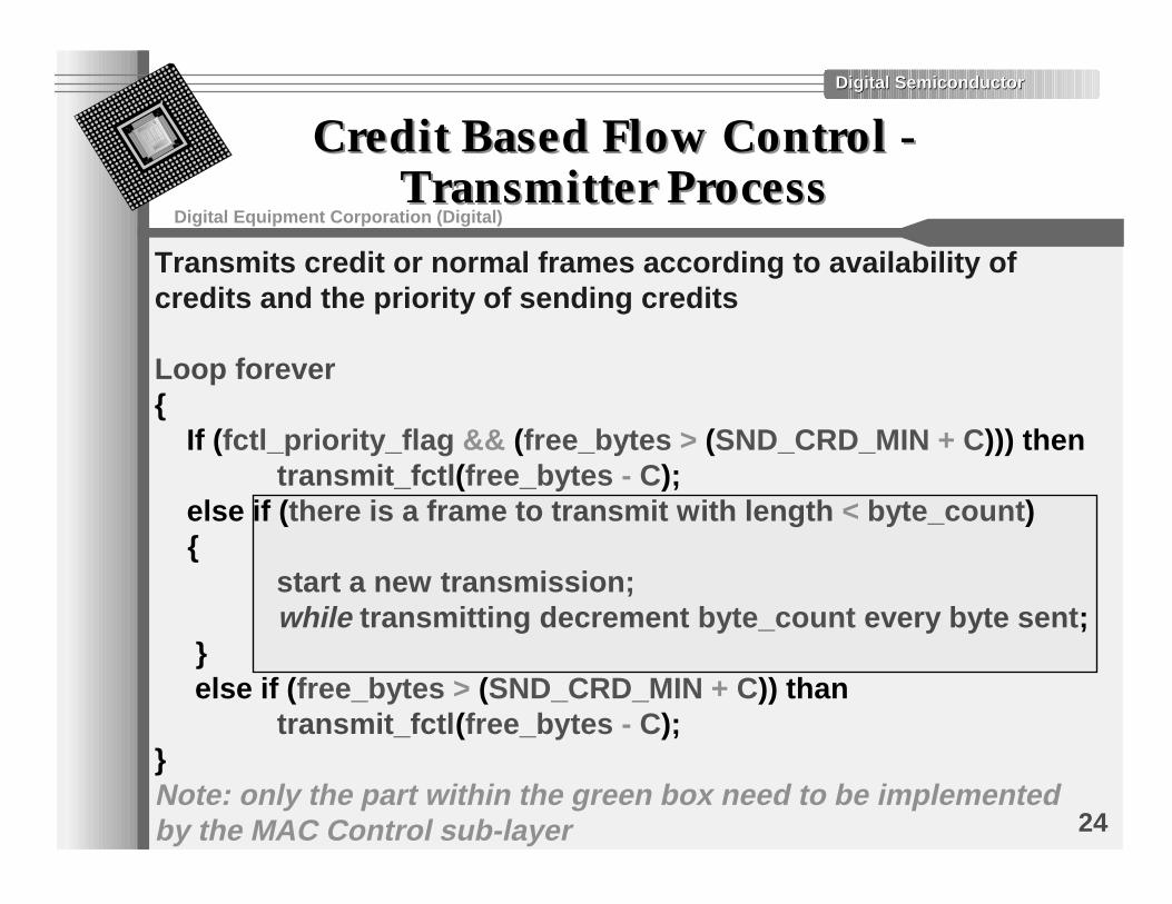
Transmits credit or normal frames according to availability of credits and the priority of sending credits
Loop forever{ If (fctl_priority_flag && (free_bytes > (SND_CRD_MIN + C))) then transmit_fctl(free_bytes - C); else if (there is a frame to transmit with length < byte_count) { start a new transmission; while transmitting decrement byte_count every byte sent; } else if (free_bytes > (SND_CRD_MIN + C)) than transmit_fctl(free_bytes - C);}Note: only the part within the green box need to be implemented by the MAC Control sub-layer
Digital SemiconductorDigital Semiconductor
Digital Equipment Corporation (Digital)
25
Credit Based Flow Control -Credit Based Flow Control -FCTL Processes & ProceduresFCTL Processes & Procedures
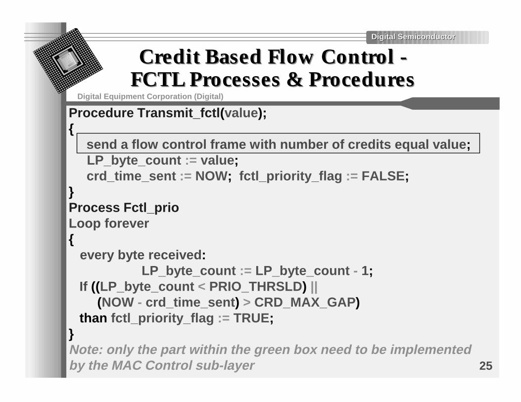
Procedure Transmit_fctl(value);{ send a flow control frame with number of credits equal value; LP_byte_count := value; crd_time_sent := NOW; fctl_priority_flag := FALSE;}Process Fctl_prioLoop forever{ every byte received: LP_byte_count := LP_byte_count - 1; If ((LP_byte_count < PRIO_THRSLD) || (NOW - crd_time_sent) > CRD_MAX_GAP) than fctl_priority_flag := TRUE;}Note: only the part within the green box need to be implemented by the MAC Control sub-layer
Digital SemiconductorDigital Semiconductor
Digital Equipment Corporation (Digital)
26
Credit Based Flow Control -Credit Based Flow Control -SummarySummary
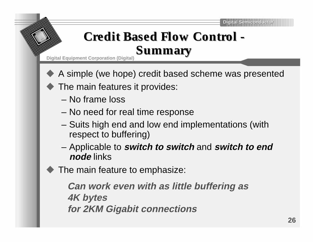
u A simple (we hope) credit based scheme was presentedu The main features it provides:
– No frame loss– No need for real time response– Suits high end and low end implementations (with
respect to buffering)– Applicable to switch to switch and switch to end
node linksu The main feature to emphasize:
Can work even with as little buffering as 4K bytes for 2KM Gigabit connections
Digital SemiconductorDigital Semiconductor
Digital Equipment Corporation (Digital)
27
Simple Rate Based Scheme -Simple Rate Based Scheme -IntroductionIntroduction
u A word of caution:– A rate based scheme can turn into a nightmare with
respect to both implementation and analysis– ... maybe this explains why a rate based scheme was
adopted by “another” technology -)• ==== > the scheme we have in mind is very (too ?) simple
u The main advantages of rate based schemes:– Do not produce the “all or none” behavior– System behavior is smoother– Involve very little computation for ports– Are (somewhat?) less affected by the length of the
linksu Main disadvantage: frames may be lost
Digital SemiconductorDigital Semiconductor
Digital Equipment Corporation (Digital)
28
Rate Based Scheme -Rate Based Scheme -ConceptConcept
u Basic idea - use IPG to control the rateu Three commands in addition to the XOFF(t):
– Set_ipg(n): ipg is set to n– Slow_down(k): ipg is multiplied by 2**k– Speed_up(l): ipg is divided by 2**l (down to current
(minimal) ipg)u Implementation is ... trivial:
– Instead of using a constant IPG use a programmablevalue which may be affected by the flow controlcommands
u An acceptable simplification:– Use only the Set_ipg(n) command
Digital SemiconductorDigital Semiconductor
Digital Equipment Corporation (Digital)
29
Rate Based Scheme -Rate Based Scheme -UsageUsage
u Not as trivial as the XOFF(t) or credit based schemes– However this is NOT the scope of 802.3
• ===> All we have to do is provide the hooks and beconvinced that they are useful
u It does NOT guarantee zero frame lossu Simplest usage:
– Define a series of high watermarks H1...Hn• Whenever we exceed a watermark we send Slow_down(1)
– Define a series of low watermark L1 ... Lk• Whenever we go under a watermark we send Speed_up(1)
– Whenever there is a major change we may use• XOFF command• Set_ipg command to set ipg to a suitable value immediately
Digital SemiconductorDigital Semiconductor
Digital Equipment Corporation (Digital)
30
Rate Based Scheme -Rate Based Scheme -EvaluationEvaluation
u Advantages:• Does not produce the “all or none” behavior• Goes well with the XOFF(t) scheme• Simpler to implement than credit based scheme• Less (directly) affected by RTD• Goes well with flow control of “other technologies”
• Provides more room for clever system design (i.e., is moreflexible) than other schemes
• Better suits Ethernet “philosophy”
u Disadvantages:• Does not guarantee zero frame loss• Usage is less straightforward than in credit based or XOFF
based schemes• More difficult to analyze
Digital SemiconductorDigital Semiconductor
Digital Equipment Corporation (Digital)
31
SummarySummary
u Frame based XOFF flow control scheme was reviewed:– No (new) advantages to PHY based flow control
• We really do not need the PHY vs. Frame based flow controldebate again in 802.3zÐ )T�MIGHT�HAVE�A�SIGNIFICANT�IMPACT�ON�SCHEDULE�AND�WILL�RAISE�ISSUES�OFCOMPATIBILITY�WITH�OTHER�PARS
Ð ����!ND�THERE�ISNÓT�ANY�ADVANTAGE�IN�0HY�BASED�SIGNALING�OVER�THECHOSEN�FRAME�BASED�SIGNALING�IN�THE�FIRST�PLACE
u Buffered repeater concept was reviewed– “Some” concerns were raised– An alternative architecture was provided
• One not involving any more work on 802.3z’s part
u Two alternative flow control schemes for GigabitEthernet were reviewed– More work is needed