FlexPod Datacenter with Microsoft SQL Server … › ... › mssql2016_flexpod_vmware_cvd.pdf1...
67
1 FlexPod Datacenter with Microsoft SQL Server 2016 and VMware vSphere 6.5 Deployment Guide for FlexPod Datacenter with Microsoft SQL Server 2016 and VMware vSphere 6.5 with Cisco UCS Manager 3.2 and ONTAP 9.3 Last Updated: June 26, 2018
Transcript of FlexPod Datacenter with Microsoft SQL Server … › ... › mssql2016_flexpod_vmware_cvd.pdf1...

1
FlexPod Datacenter with
Microsoft SQL Server 2016 and
VMware vSphere 6.5
Deployment Guide for FlexPod Datacenter with
Microsoft SQL Server 2016 and VMware vSphere
6.5 with Cisco UCS Manager 3.2 and ONTAP 9.3
Last Updated: June 26, 2018

2
About the Cisco Validated Design Program
The Cisco Validated Design (CVD) program consists of systems and solutions designed, tested, and documented to facilitate faster, more reliable, and more predictable customer deployments. For more information, visit:
http://www.cisco.com/go/designzone.
ALL DESIGNS, SPECIFICATIONS, STATEMENTS, INFORMATION, AND RECOMMENDATIONS (COLLECTIVELY, "DESIGNS") IN THIS MANUAL ARE PRESENTED "AS IS," WITH ALL FAULTS. CISCO AND ITS SUPPLIERS DISCLAIM ALL WARRANTIES, INCLUDING, WITHOUT LIMITATION, THE WARRANTY OF MERCHANTABILITY, FITNESS FOR A PARTICULAR PURPOSE AND NONINFRINGEMENT OR ARISING FROM A COURSE OF DEALING, USAGE, OR TRADE PRACTICE. IN NO EVENT SHALL CISCO OR ITS SUPPLIERS BE LIABLE FOR ANY INDIRECT, SPECIAL, CONSEQUENTIAL, OR INCIDENTAL DAMAGES, INCLUDING, WITHOUT LIMITATION, LOST PROFITS OR LOSS OR DAMAGE TO DATA ARISING OUT OF THE USE OR INABILITY TO USE THE DESIGNS, EVEN IF CISCO OR ITS SUPPLIERS HAVE BEEN ADVISED OF THE POSSIBILITY OF SUCH DAMAGES.
THE DESIGNS ARE SUBJECT TO CHANGE WITHOUT NOTICE. USERS ARE SOLELY RESPONSIBLE FOR THEIR APPLICATION OF THE DESIGNS. THE DESIGNS DO NOT CONSTITUTE THE TECHNICAL OR OTHER PROFESSIONAL ADVICE OF CISCO, ITS SUPPLIERS OR PARTNERS. USERS SHOULD CONSULT THEIR OWN TECHNICAL ADVISORS BEFORE IMPLEMENTING THE DESIGNS. RESULTS MAY VARY DEPENDING ON FACTORS NOT TESTED BY CISCO.
CCDE, CCENT, Cisco Eos, Cisco Lumin, Cisco Nexus, Cisco StadiumVision, Cisco TelePresence, Cisco WebEx, the Cisco logo, DCE, and Welcome to the Human Network are trademarks; Changing the Way We Work, Live, Play, and Learn and Cisco Store are service marks; and Access Registrar, Aironet, AsyncOS, Bringing the Meeting To You, Catalyst, CCDA, CCDP, CCIE, CCIP, CCNA, CCNP, CCSP, CCVP, Cisco, the Cisco Certified Internetwork Expert logo, Cisco IOS, Cisco Press, Cisco Systems, Cisco Systems Capital, the Cisco Systems logo, Cisco Unified Computing System (Cisco UCS), Cisco UCS B-Series Blade Servers, Cisco UCS C-Series Rack Servers, Cisco UCS S-Series Storage Servers, Cisco UCS Manager, Cisco UCS Management Software, Cisco Unified Fabric, Cisco Application Centric Infrastructure, Cisco Nexus 9000 Series, Cisco Nexus 7000 Series. Cisco Prime Data Center Network Manager, Cisco NX-OS Software, Cisco MDS Series, Cisco Unity, Collaboration Without Limitation, EtherFast, EtherSwitch, Event Center, Fast Step, Follow Me Browsing, FormShare, GigaDrive, HomeLink, Internet Quotient, IOS, iPhone, iQuick Study, LightStream, Linksys, MediaTone, MeetingPlace, MeetingPlace Chime Sound, MGX, Networkers, Networking Academy, Network Registrar, PCNow, PIX, PowerPanels, ProConnect, ScriptShare, SenderBase, SMARTnet, Spectrum Expert, StackWise, The Fastest Way to Increase Your Internet Quotient, TransPath, WebEx, and the WebEx logo are registered trademarks of Cisco Systems, Inc. and/or its affiliates in the United States and certain other countries.
All other trademarks mentioned in this document or website are the property of their respective owners. The use of the word partner does not imply a partnership relationship between Cisco and any other company. (0809R)
© 2018 Cisco Systems, Inc. All rights reserved.

3
Table of Contents
Executive Summary .............................................................................................................................................................................. 5
Solution Overview ................................................................................................................................................................................. 6
Introduction ...................................................................................................................................................................................... 6
Audience .......................................................................................................................................................................................... 6
Purpose of this Document ................................................................................................................................................................ 6
What’s New? .................................................................................................................................................................................... 6
Technology Overview ........................................................................................................................................................................... 7
FlexPod System Overview ............................................................................................................................................................... 7
FlexPod Benefits .............................................................................................................................................................................. 7
FlexPod: Cisco and NetApp Verified and Validated Architecture ..................................................................................................... 7
Integrated System ............................................................................................................................................................................ 8
Out-of-the-Box Infrastructure High Availability ................................................................................................................................. 8
FlexPod Design Principles ............................................................................................................................................................... 8
Cisco Unified Computing System ..................................................................................................................................................... 8
Cisco UCS Manager .................................................................................................................................................................... 9
Cisco UCS Fabric Interconnects ................................................................................................................................................ 10
Cisco UCS 5108 Blade Server Chassis ..................................................................................................................................... 10
Cisco UCS B200 M5 Blade Server ............................................................................................................................................ 10
Cisco UCS Fabric Extenders ..................................................................................................................................................... 11
Cisco VIC Interface Cards ......................................................................................................................................................... 12
Cisco UCS Differentiators .......................................................................................................................................................... 12
Cisco Nexus 9000 Switches ........................................................................................................................................................... 14
NetApp AFF A300 Storage ............................................................................................................................................................. 14
NetApp ONTAP 9.3 .................................................................................................................................................................... 14
NetApp SnapCenter ....................................................................................................................................................................... 15
SnapCenter Server .................................................................................................................................................................... 17
SnapCenter Plug-in for Microsoft SQL Server ........................................................................................................................... 17
SnapCenter Plug-in for Microsoft Windows ............................................................................................................................... 17
SnapCenter Plug-in for VMware vSphere .................................................................................................................................. 18
Support for Virtualized Databases and File Systems ................................................................................................................. 18
VMware vSphere 6.5 ...................................................................................................................................................................... 18
Microsoft Windows 2016 ................................................................................................................................................................ 18
Microsoft SQL Server 2016 ............................................................................................................................................................ 18
Solution Design................................................................................................................................................................................... 19
Configuration Specifications ............................................................................................................................................................... 22
Cisco UCS Manager Configuration ................................................................................................................................................ 22
BIOS Settings ............................................................................................................................................................................ 24

Executive Summary
4
VMware ESXi Host Configuration ................................................................................................................................................... 26
Power Settings ........................................................................................................................................................................... 26
ESXi Host Networking Configuration .............................................................................................................................................. 26
NetApp AFF A300 Storage Layout and Configuration .................................................................................................................... 31
Dedicated Storage Virtual Machines (SVMs) ............................................................................................................................. 31
Volume and LUN Configuration ................................................................................................................................................. 33
Creating and Deploying Virtual Machines for Hosting SQL Server Databases .............................................................................. 35
Cores per Socket ....................................................................................................................................................................... 35
Memory Reservation .................................................................................................................................................................. 35
Network Adapter Type ............................................................................................................................................................... 36
Virtual Disk Settings ................................................................................................................................................................... 36
Installing and Configuring Windows Server 2016 and Storage Configuration ............................................................................ 37
Installing SQL Server and Configuration Recommendations ..................................................................................................... 48
NetApp SnapCenter Installation and Configuration ........................................................................................................................ 51
SnapCenter 4.0 Prerequisites .................................................................................................................................................... 51
Solution Performance Testing and Validation ..................................................................................................................................... 53
Performance Test Methodology and Results ............................................................................................................................. 53
NetApp SnapCenter Validation....................................................................................................................................................... 63
Database Backup ....................................................................................................................................................................... 63
Database Cloning ...................................................................................................................................................................... 64
Database Restore ...................................................................................................................................................................... 64
Summary ............................................................................................................................................................................................ 66
About the Authors ............................................................................................................................................................................... 67
Acknowledgements ........................................................................................................................................................................ 67

Executive Summary
5
Executive Summary
It is important that a datacenter solution embrace technology advancements in various areas, such as compute, network, and storage technologies to efficiently address rapidly changing requirements and challenges of IT organizations.
FlexPod is a popular converged datacenter solution created by Cisco and NetApp. It is designed to incorporate and support a wide variety of technologies and products into the solution portfolio. There have been continuous efforts to incorporate advancements in the technologies into the FlexPod solution. This enables the FlexPod solution to offer a more robust, flexible, and resilient platform to host a wide range of enterprise applications.
This document discusses a FlexPod reference architecture using the latest hardware and software products and provides configuration recommendations for deploying Microsoft SQL Server databases in a virtualized environment.
The recommended solution architecture is built on Cisco Unified Computing System (Cisco UCS) using the unified software release to support the Cisco UCS hardware platforms including Cisco UCS B-Series Blade Servers, Cisco UCS 6300 Fabric Interconnects, Cisco Nexus 9000 Series Switches, and NetApp All Flash Series Storage Arrays. Additionally, this solution includes VMware vSphere 6.5, providing a number of new features to optimize storage utilization and facilitating private cloud.
Solution Overview
6
Solution Overview
Introduction
The current IT industry is witnessing vast transformations in the datacenter solutions. In the recent years, there is a considerable interest towards pre-validated and engineered datacenter solutions. Introduction of virtualization technology in the key areas has impacted the design principles and architectures of these solutions in a big way. It has opened up the doors for many applications running on bare metal systems to migrate to these new virtualized integrated solutions.
FlexPod System is one such pre-validated and engineered datacenter solution designed to address rapidly changing needs of IT organizations. Cisco and NetApp have partnered to deliver FlexPod, which uses best of breed compute, network and storage components to serve as the foundation for a variety of enterprise workloads including databases, ERP, CRM and Web applications, etc.
The consolidation of IT applications, particularly databases, has generated considerable interest in the recent years. Being most widely adopted and deployed database platform over several years, Microsoft SQL Server databases have become the victim of a popularly known IT challenge “Database Sprawl.” Some of the challenges of SQL Server sprawl include underutilized Servers, wrong licensing, security concerns, management concerns, huge operational costs etc. Hence SQL Server databases would be right candidate for migrating and consolidating on to a more robust, flexible and resilient platform. This document discusses a FlexPod reference architecture for deploying and consolidating SQL Server databases.
Audience
The audience for this document includes, but is not limited to; sales engineers, field consultants, professional services, IT managers, partner engineers, and customers who want to take advantage of an infrastructure built to deliver IT efficiency and enable IT innovation.
Purpose of this Document
This document discusses reference architecture and implementation guidelines for deploying and consolidating Microsoft SQL Server 2016 databases on FlexPod system.
The step-by-step process to deploy and configure the FlexPod system is not in the scope of this document.
What’s New?
The following software and hardware products distinguish the reference architecture from others.
Support for Cisco UCS B200 M5 blade servers
Support for latest release of NetApp All Flash A300 storage with Data ONTAP® 9.3 and NetApp SnapCenter 4.0 for database backup and recovery
40G end-to-end networking and storage connectivity
Support for VMWare vSphere 6.5

Technology Overview
7
Technology Overview
FlexPod System Overview
FlexPod is a best practice datacenter architecture that includes these components:
Cisco Unified Computing System (Cisco UCS)
Cisco Nexus switches
NetApp FAS or AFF storage, NetApp E-Series storage systems, and / or NetApp SolidFire
These components are connected and configured according to best practices of both Cisco and NetApp, and provide the ideal platform for running multiple enterprise workloads with confidence. The reference architecture covered in this document leverages the Cisco Nexus 9000 Series switch. One of the key benefits of FlexPod is the ability to maintain consistency at scaling, including scale up and scale out. Each of the component families shown in Figure 7 (Cisco Unified Computing System, Cisco Nexus, and NetApp storage systems) offers platform and resource options to scale the infrastructure up or down, while supporting the same features and functionality that are required under the configuration and connectivity best practices of FlexPod.
FlexPod Benefits
As customers transition toward shared infrastructure or cloud computing they face a number of challenges such as initial transition hiccups, return on investment (ROI) analysis, infrastructure management and future growth plan. The FlexPod architecture is designed to help with proven guidance and measurable value. By introducing standardization, FlexPod helps customers mitigate the risk and uncertainty involved in planning, designing, and implementing a new datacenter infrastructure. The result is a more predictive and adaptable architecture capable of meeting and exceeding customers' IT demands.
The following list provides the unique features and benefits that FlexPod system provides for consolidation SQL Server database deployments.
1. Support for latest Intel® Xeon® processor scalable family CPUs, UCS B200 M5 blades enables consolidating more SQL Server VMs and there by achieving higher consolidation ratios reducing Total Cost of Ownership and achieving quick ROIs.
2. End to End 40 Gbps networking connectivity using Cisco third-generation fabric interconnects, Nexus 9000 se-ries switches and NetApp AFF A300 storage Arrays.
3. Blazing IO performance using NetApp All Flash Storage Arrays and Complete SQL Server database protection using NetApp Snapshots & Direct storage access to SQL VMs using in-guest iSCSI Initiator.
4. Non-disruptive policy based management of infrastructure using Cisco UCS Manager.
FlexPod: Cisco and NetApp Verified and Validated Architecture
Cisco and NetApp have thoroughly validated and verified the FlexPod solution architecture and its many use cases while creating a portfolio of detailed documentation, information, and references to assist customers in transforming their datacenters to this shared infrastructure model. This portfolio includes, but is not limited to the following items:
Best practice architectural design
Workload sizing and scaling guidance

Technology Overview
8
Implementation and deployment instructions
Technical specifications (rules for FlexPod configuration do's and don’ts)
Frequently asked questions (FAQs)
Cisco Validated Designs (CVDs) and NetApp Verified Architectures (NVAs) focused on many use cases
Cisco and NetApp have also built a robust and experienced support team focused on FlexPod solutions, from customer account and technical sales representatives to professional services and technical support engineers. The cooperative support program extended by Cisco and NetApp provides customers and channel service partners with direct access to technical experts who collaborate with cross vendors and have access to shared lab resources to resolve potential issues. FlexPod supports tight integration with virtualized and cloud infrastructures, making it a logical choice for long-term investment. The following IT initiatives are addressed by the FlexPod solution.
Integrated System
FlexPod is a pre-validated infrastructure that brings together compute, storage, and network to simplify, accelerate, and minimize the risk associated with datacenter builds and application rollouts. These integrated systems provide a standardized approach in the datacenter that facilitates staff expertise, application onboarding, and automation as well as operational efficiencies relating to compliance and certification.
Out-of-the-Box Infrastructure High Availability
FlexPod is a highly available and scalable infrastructure that IT can evolve over time to support multiple physical and virtual application workloads. FlexPod has no single point of failure at any level, from the server through the network, to the storage. The fabric is fully redundant and scalable, and provides seamless traffic failover, should any individual component fail at the physical or virtual layer.
FlexPod Design Principles
FlexPod addresses four primary design principles:
Application availability: Makes sure that services are accessible and ready to use.
Scalability: Addresses increasing demands with appropriate resources.
Flexibility: Provides new services or recovers resources without requiring infrastructure modifications.
Manageability: Facilitates efficient infrastructure operations through open standards and APIs.
The following sections provides a brief introduction of the various hardware/ software components used in this solution.
Cisco Unified Computing System
The Cisco Unified Computing System is a next-generation solution for blade and rack server computing. The system integrates a low-latency; lossless 40 Gigabit Ethernet unified network fabric with enterprise-class, x86-architecture servers. The system is an integrated, scalable, multi-chassis platform in which all resources participate in a unified management domain. The Cisco Unified Computing System accelerates the delivery of new services simply, reliably, and securely through end-to-end provisioning and migration support for both virtualized and non-virtualized systems. Cisco Unified Computing System provides:
Comprehensive Management
Radical Simplification
Technology Overview
9
High Performance
The Cisco Unified Computing System consists of the following components:
Compute - The system is based on an entirely new class of computing system that incorporates rack mount and blade servers based on Intel® Xeon® scalable processors product family.
Network - The system is integrated onto a low-latency, lossless, 40-Gbps unified network fabric. This network foundation consolidates Local Area Networks (LAN’s), Storage Area Networks (SANs), and high-performance computing networks which are separate networks today. The unified fabric lowers costs by reducing the number of network adapters, switches, and cables, and by decreasing the power and cooling requirements.
Virtualization - The system unleashes the full potential of virtualization by enhancing the scalability, performance, and operational control of virtual environments. Cisco security, policy enforcement, and diagnostic features are now extended into virtualized environments to better support changing business and IT requirements.
Storage access - The system provides consolidated access to both SAN storage and Network Attached Storage (NAS) over the unified fabric. It is also an ideal system for Software defined Storage (SDS). Combining the benefits of single framework to manage both the compute and Storage servers in a single pane, Quality of Service (QOS) can be implemented if needed to inject IO throttling in the system. In addition, the server administrators can pre-assign storage-access policies to storage resources, for simplified storage connectivity and management leading to increased productivity. In addition to external storage, both rack and blade servers have internal storage which can be accessed through built-in hardware RAID controllers. With storage profile and disk configuration policy configured in Cisco UCS Manager, storage needs for the host OS and application data gets fulfilled by user defined RAID groups for high availability and better performance.
Management - the system uniquely integrates all system components to enable the entire solution to be managed as a single entity by the Cisco UCS Manager. The Cisco UCS Manager has an intuitive graphical user interface (GUI), a command-line interface (CLI), and a powerful scripting library module for Microsoft PowerShell built on a robust application programming interface (API) to manage all system configuration and operations.
Cisco Unified Computing System (Cisco UCS) fuses access layer networking and servers. This high-performance, next-generation server system provides a data center with a high degree of workload agility and scalability.
Cisco UCS Manager
Cisco UCS Manager (UCSM) provides unified, embedded management for all software and hardware components in the Cisco UCS. Using Single Connect technology, it manages, controls, and administers multiple chassis for thousands of virtual machines. Administrators use the software to manage the entire Cisco Unified Computing System as a single logical entity through an intuitive GUI, a command-line interface (CLI), or an XML API. Cisco UCS Manager resides on a pair of Cisco UCS 6300 Series Fabric Interconnects using a clustered, active-standby configuration for high-availability.
Cisco UCS Manager offers unified embedded management interface that integrates server, network, and storage. Cisco UCS Manager performs auto-discovery to detect inventory, manage, and provision system components that are added or changed. It offers comprehensive set of XML API for third part integration, exposes 9000 points of integration and facilitates custom development for automation, orchestration, and to achieve new levels of system visibility and control.
Service profiles benefit both virtualized and non-virtualized environments and increase the mobility of non-virtualized servers, such as when moving workloads from server to server or taking a server offline for service or upgrade. Profiles can also be used in conjunction with virtualization clusters to bring new resources online easily, complementing existing virtual machine mobility.

Technology Overview
10
For more Cisco UCS Manager Information, refer to: http://www.cisco.com/c/en/us/products/servers-unified-computing/ucs-manager/index.html.
Cisco UCS Fabric Interconnects
The Fabric interconnects provide a single point for connectivity and management for the entire system. Typically deployed as an active-active pair, the system’s fabric interconnects integrate all components into a single, highly-available management domain controlled by Cisco UCS Manager. The fabric interconnects manage all I/O efficiently and securely at a single point, resulting in deterministic I/O latency regardless of a server or virtual machine’s topological location in the system.
Cisco UCS 6300 Series Fabric Interconnects support the bandwidth up to 2.43-Tbps unified fabric with low-latency, lossless, cut-through switching that supports IP, storage, and management traffic using a single set of cables. The fabric interconnects feature virtual interfaces that terminate both physical and virtual connections equivalently, establishing a virtualization-aware environment in which blade, rack servers, and virtual machines are interconnected using the same mechanisms. The Cisco UCS 6332-16UP is a 1-RU Fabric Interconnect that features up to 40 universal ports that can support 24 40-Gigabit Ethernet, Fiber Channel over Ethernet, or native Fiber Channel connectivity. In addition to this it supports up to 16 1- and 10-Gbps FCoE or 4-, 8- and 16-Gbps Fibre Channel unified ports.
Figure 1 Cisco UCS Fabric Interconnect 6332-16UP
For more information, refer to: https://www.cisco.com/c/en/us/products/servers-unified-computing/ucs-6332-16up-fabric-interconnect/index.html
Cisco UCS 5108 Blade Server Chassis
The Cisco UCS 5100 Series Blade Server Chassis is a crucial building block of the Cisco Unified Computing System, delivering a scalable and flexible blade server chassis. The Cisco UCS 5108 Blade Server Chassis is six rack units (6RU) high and can mount in an industry-standard 19-inch rack. A single chassis can house up to eight half-width Cisco UCS B-Series Blade Servers and can accommodate both half-width and full-width blade form factors. Four single-phase, hot-swappable power supplies are accessible from the front of the chassis. These power supplies are 92 percent efficient and can be configured to support non-redundant, N+ 1 redundant and grid-redundant configurations. The rear of the chassis contains eight hot-swappable fans, four power connectors (one per power supply), and two I/O bays for Cisco UCS 2304 Fabric Extenders. A passive mid-plane provides multiple 40 Gigabit Ethernet connections between blade serves and fabric interconnects. The Cisco UCS 2304 Fabric Extender has four 40 Gigabit Ethernet, FCoE-capable, Quad Small Form-Factor Pluggable (QSFP+) ports that connect the blade chassis to the fabric interconnect. Each Cisco UCS 2304 can provide one 40 Gigabit Ethernet ports connected through the midplane to each half-width slot in the chassis, giving it a total eight 40G interfaces to the compute. Typically configured in pairs for redundancy, two fabric extenders provide up to 320 Gbps of I/O to the chassis.
For more information, refer to: http://www.cisco.com/c/en/us/products/servers-unified-computing/ucs-5100-series-blade-server-chassis/index.html
Cisco UCS B200 M5 Blade Server
The Cisco UCS B200 M5 Blade Server delivers performance, flexibility, and optimization for deployments in data centers, in the cloud, and at remote sites. This enterprise-class server offers market-leading performance, versatility, and density without compromise for workloads including Virtual Desktop Infrastructure (VDI), web infrastructure, distributed databases, converged infrastructure, and enterprise applications such as Oracle and SAP HANA. The Cisco UCS B200 M5 server can quickly deploy stateless physical and virtual workloads through

Technology Overview
11
programmable, easy-to-use Cisco UCS Manager Software and simplified server access through Cisco SingleConnect technology. The Cisco UCS B200 M5 server is a half-width blade. Up to eight servers can reside in the 6-Rack-Unit (6RU) Cisco UCS 5108 Blade Server Chassis, offering one of the highest densities of servers per rack unit of blade chassis in the industry. You can configure the Cisco UCS B200 M5 to meet your local storage requirements without having to buy, power, and cool components that you do not need. The Cisco UCS B200 M5 blade server provides these main features:
Up to two Intel Xeon Scalable CPUs with up to 28 cores per CPU
24 DIMM slots for industry-standard DDR4 memory at speeds up to 2666 MHz, with up to 3 TB of total memory when using 128-GB DIMMs
Modular LAN On Motherboard (mLOM) card with Cisco UCS Virtual Interface Card (VIC) 1340, a 2-port, 40 Gigabit Ethernet, Fibre Channel over Ethernet (FCoE)–capable mLOM mezzanine adapter
Optional rear mezzanine VIC with two 40-Gbps unified I/O ports or two sets of 4 x 10-Gbps unified I/O ports, delivering 80 Gbps to the server; adapts to either 10- or 40-Gbps fabric connections
Two optional, hot-pluggable, Hard-Disk Drives (HDDs), Solid-State Disks (SSDs), or NVMe 2.5-inch drives with a choice of enterprise-class RAID or pass-through controllers
Figure 2 Cisco UCS B200 M5 Blade Server
For more information, refer to: https://www.cisco.com/c/en/us/products/collateral/servers-unified-computing/ucs-b-series-blade-servers/datasheet-c78-739296.html
Cisco UCS Fabric Extenders
Cisco UCS 2304 Fabric Extender brings the unified fabric into the blade server enclosure, providing multiple 40 Gigabit Ethernet connections between blade servers and the fabric interconnect, simplifying diagnostics, cabling, and management. It is a third-generation I/O Module (IOM) that shares the same form factor as the second-generation Cisco UCS 2200 Series Fabric Extenders and is backward compatible with the shipping Cisco UCS 5108 Blade Server Chassis. The Cisco UCS 2304 connects the I/O fabric between the Cisco UCS 6300 Series Fabric Interconnects and the Cisco UCS 5100 Series Blade Server Chassis, enabling a lossless and deterministic Fibre Channel over Ethernet (FCoE) fabric to connect all blades and chassis together. Because the fabric extender is similar to a distributed line card, it does not perform any switching and is managed as an extension of the fabric interconnects. This approach reduces the overall infrastructure complexity and enabling Cisco UCS to scale to many chassis without multiplying the number of switches needed, reducing TCO and allowing all chassis to be managed as a single, highly available management domain.
The Cisco UCS 2304 Fabric Extender has four 40Gigabit Ethernet, FCoE-capable, Quad Small Form-Factor Pluggable (QSFP+) ports that connect the blade chassis to the fabric interconnect. Each Cisco UCS 2304 can provide one 40 Gigabit Ethernet ports connected through the midplane to each half-width slot in the chassis, giving it a total eight 40G interfaces to the compute. Typically configured in pairs for redundancy, two fabric extenders provide up to 320 Gbps of I/O to the chassis.
! ResetConsole
UCS-HD300G10L12G126bps 10K SAS300GB
!
UCS B200 M5
UCS-HD300G10L12G126bps 10K SAS300GB
!

Technology Overview
12
Figure 3 Cisco UCS 2304 Fabric Extender
For more information, refer to: https://www.cisco.com/c/en/us/products/collateral/servers-unified-computing/ucs-6300-series-fabric-interconnects/datasheet-c78-675243.html
Cisco VIC Interface Cards
The Cisco UCS Virtual Interface Card (VIC) 1340 is a 2-port 40-Gbps Ethernet or dual 4 x 10-Gbps Ethernet, Fiber Channel over Ethernet (FCoE) capable modular LAN on motherboard (mLOM) designed exclusively for the M4 generation of Cisco UCS B-Series Blade Servers. All the blade servers for both Controllers and Computes will have MLOM VIC 1340 card. Each blade will have a capacity of 40Gb of network traffic. The underlying network interfaces will share this MLOM card.
The Cisco UCS VIC 1340 enables a policy-based, stateless, agile server infrastructure that can present over 256 PCIe standards-compliant interfaces to the host that can be dynamically configured as either network interface cards (NICs) or host bus adapters (HBAs).
For more information, refer to: http://www.cisco.com/c/en/us/products/interfaces-modules/ucs-virtual-interface-card-1340/index.html
Cisco UCS Differentiators
Cisco Unified Computing System is revolutionizing the way servers are managed in the data center. The following are the unique differentiators of Cisco UCS and Cisco UCS Manager:
1. Embedded Management —In Cisco UCS, the servers are managed by the embedded firmware in the Fabric Interconnects, eliminating need for any external physical or virtual devices to manage the servers.
2. Unified Fabric —In Cisco UCS, from blade server chassis or rack servers to FI, there is a single Ethernet cable used for LAN, SAN and management traffic. This converged I/O results in reduced cables, SFPs and adapters which in turn reduce capital and operational expenses of the overall solution.
3. Auto Discovery —By simply inserting the blade server in the chassis or connecting rack server to the fabric in-terconnect, discovery and inventory of compute resource occurs automatically without any management inter-vention. The combination of unified fabric and auto-discovery enables the wire-once architecture of Cisco UCS, where its compute capability can be extended easily while keeping the existing external connectivity to LAN, SAN and management networks.
UCS-IOM-2304
1
2
3
4
Technology Overview
13
4. Policy Based Resource Classification —When a compute resource is discovered by Cisco UCS Manager, it can be automatically classified to a given resource pool based on policies defined. This capability is useful in multi-tenant cloud computing. This CVD showcases the policy-based resource classification of Cisco UCS Manager.
5. Combined Rack and Blade Server Management —Cisco UCS Manager can manage B-Series blade servers and C-Series rack server under the same Cisco UCS domain. This feature, along with stateless computing makes compute resources truly hardware form factor agnostic.
6. Model based Management Architecture —Cisco UCS Manager Architecture and management database is model based and data driven. An open XML API is provided to operate on the management model. This ena-bles easy and scalable integration of Cisco UCS Manager with other management systems.
7. Policies, Pools, Templates —The management approach in Cisco UCS Manager is based on defining policies, pools and templates, instead of cluttered configuration, which enables a simple, loosely coupled, data driven approach in managing compute, network and storage resources.
8. Loose Referential Integrity —In Cisco UCS Manager, a service profile, port profile or policies can refer to other policies or logical resources with loose referential integrity. A referred policy cannot exist at the time of author-ing the referring policy or a referred policy can be deleted even though other policies are referring to it. This provides different subject matter experts to work independently from each-other. This provides great flexibility where different experts from different domains, such as network, storage, security, server and virtualization work together to accomplish a complex task.
9. Policy Resolution —In Cisco UCS Manager, a tree structure of organizational unit hierarchy can be created that mimics the real-life tenants and/or organization relationships. Various policies, pools and templates can be defined at different levels of organization hierarchy. A policy referring to another policy by name is resolved in the organization hierarchy with closest policy match. If no policy with specific name is found in the hierarchy of the root organization, then special policy named “default” is searched. This policy resolution practice enables automation friendly management APIs and provides great flexibility to owners of different organizations.
10. Service Profiles and Stateless Computing —a service profile is a logical representation of a server, carrying its various identities and policies. This logical server can be assigned to any physical compute resource as far as it meets the resource requirements. Stateless computing enables procurement of a server within minutes, which used to take days in legacy server management systems.
11. Built-in Multi-Tenancy Support —The combination of policies, pools and templates, loose referential integrity, policy resolution in organization hierarchy and a service profiles based approach to compute resources makes Cisco UCS Manager inherently friendly to multi-tenant environment typically observed in private and public clouds.
12. Extended Memory —the enterprise-class Cisco UCS B200 M5 blade server extends the capabilities of Cisco’s Unified Computing System portfolio in a half-width blade form factor. The Cisco UCS B200 M5 harnesses the power of the latest Intel® Xeon® scalable processors product family CPUs with up to 3 TB of RAM– allowing huge VM to physical server ratio required in many deployments, or allowing large memory operations required by certain architectures like Big-Data.
13. Virtualization Aware Network —VM-FEX technology makes the access network layer aware about host virtual-ization. This prevents domain pollution of compute and network domains with virtualization when virtual net-work is managed by port-profiles defined by the network administrators’ team. VM-FEX also off-loads hypervi-sor CPU by performing switching in the hardware, thus allowing hypervisor CPU to do more virtualization re-lated tasks. VM-FEX technology is well integrated with VMware vCenter, Linux KVM and Hyper-V SR-IOV to simplify cloud management.
14. Simplified QoS —Even though Fiber Channel and Ethernet are converged in Cisco UCS fabric, built-in support for QoS and lossless Ethernet makes it seamless. Network Quality of Service (QoS) is simplified in Cisco UCS Manager by representing all system classes in one GUI panel.

Technology Overview
14
Cisco Nexus 9000 Switches
The Cisco Nexus 9000 Series delivers proven high-performance and density, low latency, and exceptional power efficiency in a broad range of compact form factors. Operating in Cisco NX-OS Software mode or in Application Centric Infrastructure (ACI) mode, these switches are ideal for traditional or fully automated data center deployments.
The Cisco Nexus 9000 Series Switches offer both modular and fixed 10/40/100 Gigabit Ethernet switch configurations with scalability up to 30 Tbps of non-blocking performance with less than five-microsecond latency, 1152 x 10 Gbps or 288 x 40 Gbps non-blocking Layer 2 and Layer 3 Ethernet ports and wire speed VXLAN gateway, bridging, and routing.
Figure 4 Cisco UCS Nexus 9396PX
For more information, refer to: https://www.cisco.com/c/en/us/products/collateral/switches/nexus-9000-series-switches/datasheet-c78-736967.html
NetApp AFF A300 Storage
With the new A-Series All Flash FAS (AFF) controller lineup, NetApp provides industry leading performance while continuing to provide a full suite of enterprise-grade data management and data protection features. The A-Series lineup offers double the IOPS, while decreasing the latency.
This solution utilizes the NetApp AFF A300. This controller provides the high performance benefits of 40GbE and all flash SSDs, while taking up only 5U of rack space. Configured with 24 x 3.8TB SSD, the A300 provides ample performance and over 60TB effective capacity. This makes it an ideal controller for a shared workload converged infrastructure. For situations where more performance is needed, the A700s would be an ideal fit.
Figure 5 NetApp AFF A300 AFFA300
NV
2
10e
0f
e0e
e0f
0g
0h
e0g
e0he0b
e0a
e0d
e0c
0a 0b 0c 0d
LNK ! LNK !LNK ! LNK !
NV
2
10e
0f
e0e
e0f
0g
0h
e0g
e0he0b
e0a
e0d
e0c
0a 0b 0c 0d
LNK ! LNK !LNK ! LNK !
NetApp ONTAP 9.3
ONTAP 9.3 is the latest-generation storage operating system from NetApp that enables businesses to modernize their infrastructure and transition to a cloud-ready data center. Leveraging industry-leading data management

Technology Overview
15
capabilities, ONTAP enables customers to manage and protect data with a single set of tools regardless of where it resides, and freely move data to wherever it’s needed: edge, core and cloud. ONTAP 9.3 includes numerous features that simplify data management, accelerate and protect critical data assets, and future-proof infrastructure across hybrid cloud architectures.
Simplify Data Management
Data management is critical to enterprise IT operations to ensure appropriate resources are used for various applications and data sets. ONTAP includes the following features to streamline and simplify operations and reduce total cost of ownership:
Inline data compaction and expanded deduplication- Data compaction reduces “wasted” space inside storage blocks for small-block data types, and aggregate-level deduplication significantly increases effective capacity by deduplicating blocks across every volume in the aggregate.
QoS Minimum, Maximum and Adaptive- ONTAP now features granular QoS controls, enabling businesses to ensure performance for critical applications in highly shared environments.
ONTAP FabricPool- Customers can now automatically tier cold data to several public and private cloud storage options including AWS, Azure and NetApp StorageGrid, allowing them to reclaim capacity and consolidate more workloads on existing systems.
Support for 15TB SSD and large-scale storage clusters- ONTAP supports the largest SSDs currently available and scales up to 12 nodes in SAN configurations or 24 nodes for NAS to deliver the highest possible capacity as a single managed device.
Accelerate and Protect Data
ONTAP has always delivered the highest levels of performance and data protection, and with several new features ONTAP 9 extends these capabilities even further:
Code-level optimizations for performance and lower latency- NetApp continues to refine ONTAP to ensure the highest possible throughput at the lowest possible latency.
Integrated Data Protection- ONTAP includes built-in data protection capabilities with common management across all platforms, enabling secondary copies of data to be used for DR testing, Backup/Archive, Test/Dev, Analytics/Reporting or any other business use.
Future-proof Infrastructure
ONTAP 9 offers support for the latest features and technologies to help customers meet demanding and constantly changing business needs:
Seamless scale and Non-disruptive operations- ONTAP supports non-disruptive addition of capacity to existing controllers as well as scale-out clusters using a choice of flash and hybrid nodes.
Cloud-connected- ONTAP is the most cloud-connected storage operating system, with options for software-defined storage (ONTAP Select) and cloud-native instances (ONTAP Cloud) in all the public cloud providers, all with consistent data management capabilities that enable true hybrid cloud flexibility.
Integration with emerging applications- ONTAP 9 provides enterprise-grade data services for next-generation platforms and applications such as OpenStack, Docker/Kubernetes, Hadoop and MongoDB using the same infrastructure that supports existing enterprise apps.
NetApp SnapCenter
SnapCenter is a unified, scalable platform for data protection. SnapCenter provides centralized control and oversight, while delegating the ability for users to manage application-consistent, database-consistent, and virtual machines (VMs) backup, restore, and clone operations. With SnapCenter, database, storage, and virtualization

Technology Overview
16
administrators learn a single tool to manage backup, restore, and clone operations for a variety of applications, databases, and VMs.
SnapCenter enables centralized application resource management and easy data protection job execution through the use of resource groups and policy management (including scheduling and retention settings). SnapCenter provides unified reporting through the use of a dashboard, multiple reporting options, job monitoring, and log and event viewers.
SnapCenter includes the following key features:
A unified and scalable platform across applications and database environments, and virtual and non-virtual storage, powered by SnapCenter Server
Role-based access control (RBAC) for security and centralized role delegation
Application-consistent Snapshot copy management, restore, clone, and backup verification support from both primary and secondary destinations (SnapMirror and SnapVault)
Remote plug-in package installation from the SnapCenter graphical user interface
Nondisruptive, remote upgrades
A dedicated SnapCenter repository that provides fast data retrieval
Load balancing implemented using Microsoft Windows Network Load Balancing (NLB) and Application Request Routing (ARR), with support for horizontal scaling
Centralized scheduling and policy management to support backup and clone operations
Centralized reporting, monitoring, and Dashboard views
The SnapCenter platform is based on a multitier architecture that includes a centralized management server (SnapCenter Server) and a SnapCenter host agent.
Figure 6 NetApp SnapCenter deployment

Technology Overview
17
The following SnapCenter components were used in this validation:
SnapCenter Server
The SnapCenter Server(s) includes a web server, a centralized HTML5-based user interface, PowerShell cmdlets, APIs, and the SnapCenter repository. SnapCenter enables load balancing, high availability, and horizontal scaling across multiple SnapCenter Servers within a single user interface. You can accomplish high availability by using Network Load Balancing (NLB) and Application Request Routing (ARR) with SnapCenter. For larger environments with thousands of hosts, adding multiple SnapCenter Servers can help balance the load.
SnapCenter Plug-in for Microsoft SQL Server
The Plug-in for SQL Server is a host-side component of the NetApp storage solution offering application-aware backup management of Microsoft SQL Server databases. With the plug-in installed on your SQL Server host, SnapCenter automates Microsoft SQL Server database backup, restore, and clone operations.
SnapCenter Plug-in for Microsoft Windows
The Plug-in for Windows is a host-side component of the NetApp storage solution that enables application-aware data protection for other plug-ins. The Plug-in for Windows enables storage provisioning, Snapshot copy consistency, and space reclamation for Windows hosts. It also enables application-aware data protection of Microsoft file systems.

Technology Overview
18
SnapCenter Plug-in for VMware vSphere
The Plug-in for VMware vSphere is a host-side component of the NetApp storage solution. It provides a vSphere web client GUI on vCenter to protect VMware virtual machines and datastores, and supports SnapCenter application-specific plug-ins in protecting virtualized databases and file systems.
Support for Virtualized Databases and File Systems
The Plug-in for VMware vSphere provides native backup, recovery, and cloning of virtualized applications (virtualized SQL and Oracle databases and Windows file systems) when using the SnapCenter GUI. SnapCenter natively leverages the Plug-in for VMware vSphere for all SQL, Oracle, and Windows file system data protection operations on virtual machine disks (VMDKs), raw device mappings (RDMs), and NFS datastores.
VMware vSphere 6.5
VMWare vSphere 6.5 is the industry leading virtualization platform. VMware ESXi 6.5 is used to deploy and run the virtual machines. VCenter Server Appliance 6.5 is used to manage the ESXi hosts and virtual machines. Multiple ESXi hosts running on Cisco UCS B200 M5 blades are used form a VMware ESXi cluster. VMware ESXi cluster pool the compute, memory and network resources from all the cluster nodes and provides resilient platform for virtual machines running on the cluster. VMware ESXi cluster features, VSphere High Availability (HA) and Distributed Resources Scheduler (DRS), contribute to the tolerance of the VSphere Cluster withstanding failures as well as distributing the resources across the VMWare ESXi hosts.
Microsoft Windows 2016
Windows Server 2016 is the latest OS platform release from Microsoft. Windows 2016 server provides great platform to run SQL Server 2016 databases. It brings in more features and enhancements around various aspects like security, patching, domains, cluster, storage, and support for various new hardware features etc. This enables windows server to provide best-in-class performance and highly scalable platform for deploying SQL Server databases.
Microsoft SQL Server 2016
Microsoft SQL Server 2016 is the recent relational database engine from Microsoft. It brings in lot of new features and enhancements to the relational and analytical engines. Being most widely adopted and deployed database platform over several years, IT organization facing database sprawl and that would lead to underutilization of hardware resources and datacenter footprint, higher power consumption, uncontrolled licensing, difficulties in managing hundreds or thousands of SQL instances. To avoid, SQL Server sprawl, IT departments are looking for consolidation of SQL Server databases as a solution.
It is recommended to use Microsoft Assessment and Planning (MAP) toolkit when customer are planning for SQL Server database consolidation or migration. MAP toolkit scans existing infrastructure and gets the complete inventory of SQL Server installations in the network. Please read the Microsoft Developer Network article here for additional information about the MAP tool for SQL Server databases.

Solution Design
19
Solution Design
This section provides an overview of the hardware and software components used in this solution, as well as the design factors to be considered in order to make the system work as a single, highly available solution.
FlexPod is a defined set of hardware and software that serves as an integrated foundation for both virtualized and non-virtualized solutions. This FlexPod Datacenter solution includes NetApp All Flash storage, Cisco Nexus® networking, the Cisco Unified Computing System (Cisco UCS®), and VMware vSphere software in a single package. The design is flexible enough that the networking, computing, and storage can fit in one data center rack or be deployed according to a customer's data center design. Port density enables the networking components to accommodate multiple configurations of this kind.
One benefit of the FlexPod architecture is the ability to customize or "flex" the environment to suit a customer's requirements. A FlexPod can easily be scaled as requirements and demand change. The unit can be scaled both up (adding resources to a FlexPod unit) and out (adding more FlexPod units). The reference architecture detailed in this document highlights the resiliency, cost benefit, and ease of deployment of an IP-based storage solution. A storage system capable of serving multiple protocols across a single interface allows for customer choice and investment protection because it truly is a wire-once architecture.
The following figure shows the FlexPod Datacenter components and the network connections for a configuration with the Cisco UCS 6332-16UP Fabric Interconnects. This design has end-to-end 40 Gb Ethernet connections between the Cisco UCS 5108 Blade Chassis and the Cisco UCS Fabric Interconnect, between the Cisco UCS Fabric Interconnect and Cisco Nexus 9000, and between Cisco Nexus 9000 and NetApp AFF A300. This infrastructure is deployed to provide iSCSI-booted hosts with file-level and block-level access to shared storage. The reference architecture reinforces the "wire-once" strategy, because as additional storage is added to the architecture, no re-cabling is required from the hosts to the Cisco UCS fabric interconnect.
It is recommended to deploy infrastructure services such as Active Directory, DNS, NTP and VMWare vCenter outside the FlexPod system. In case if customers have these services already available in their data center, these services can be leveraged to manage the FlexPod system.

Solution Design
20
Figure 7 FlexPod with Cisco UCS B200 M5, Nexus 93180YC, and NetApp AFF A300
Figure 7 illustrates a base design. Each of the components can be scaled easily to support specific business requirements. For example, more (or different) servers or even blade chassis can be deployed to increase compute capacity, additional storage controllers or disk shelves can be deployed to improve I/O capability and throughput, and special hardware or software features can be added to introduce new features.
Table 1 lists the hardware and software components along with image versions used in the solution.
Table 1 Hardware and Software Components Specifications
Component Device Details
Compute 1x Cisco UCS 5108 blade chassis with 2x Cisco UCS 2304 IO
Modules
4x Cisco UCS B200 M5 blades each with one Cisco UCS VIC
1340 adapter
Fabric Interconnects 2x Cisco UCS third-generation 6332-16UP
Cisco UCS Manager Firmware : 3.2(2d)

Solution Design
21
Component Device Details
Network Switches 2x Cisco Nexus 93180YC switches
NX-OS: 7.0(3)I4(5)
Storage Controllers 2x NetApp AFF A300 storage controllers with ONTAP 9.3
NetApp Virtual Storage Console (VSC) 7.1p1
NetApp Host Utilities Kit for Windows 7.1
Hypervisor VMWare vSphere 6.5 Update 1
VMware vCenter Server Appliance (VSA) 6.5 Update 1f
Guest Operating System Windows 2016 Standard Edition
Database software SQL Server 2016 SP1 Enterprise Edition

Configuration Specifications
22
Configuration Specifications
It is important that the configuration best practices are followed in order to achieve optimal performance from the system for a specific workload.
This section focuses on the important configuration aspects specific to database workloads. For detailed deployment information, refer to the FlexPod Datacenter with VMware vSphere 6.5 CVD.
Cisco UCS Manager Configuration
This section discusses only the Cisco UCS Manager policies that are different from the base FlexPod infrastructure. These changes are required for obtaining optimal performance for SQL Server workloads.
For the detailed step-by-step process to configure the FlexPod base infrastructure, refer to the FlexPod Datacenter with VMware vSphere 6.5, NetApp AFF A-Series and IP-Based Storage Deployment Guide.
The Transmit Queues, Receive Queues defined in the default VMware Adapter policy may eventually get exhausted as more SQL Server databases are consolidated on the FlexPod System. It is recommended to use higher queues on the vNICs that are used for iSCSI storage traffic for better storage throughput. Create a new adapter policy with the setting as shown below and apply it on the vNICs that are used for iSCSI guest storage traffic.

Configuration Specifications
23
Figure 8 Adapter Policy for Higher IO Throughput

Configuration Specifications
24
As shown in Figure 9 and Figure 10, using the LAN connectivity policy, the above adapter policy can be applied to vNICs that are created for serving iSCSI storage traffic to the SQL Guest VMs.
Figure 9 LAN Connectivity Policy
Figure 10 Applying Adapter Policy Using LAN Connectivity Policy
BIOS Settings
It is recommended to use appropriate BIOS settings on the servers based on the workload they run. The following BIOS settings are used in our performance tests for obtaining optimal system performance for SQL Server OLTP workloads on Cisco UCS B200 M5 server.

Configuration Specifications
25
Figure 11 Cisco UCS B200 M5 BIOS Setting

Configuration Specifications
26
VMware ESXi Host Configuration
This section discusses the VMWare ESXi host specific configuration which are different from the base FlexPod in-frastructure. These changes are required for achieving optimal system performance for SQL Server workloads.
Power Settings
An ESXi host can take advantage of several power management features that the hardware provides to adjust the trade-off between performance and power use. You can control how ESXi uses these features by selecting a power management policy.
ESXi has been heavily tuned for driving high I/O throughput efficiently by utilizing fewer CPU cycles and conserving power. Hence the Power setting on the ESXi host is set to “Balanced.” However, for critical database deployments, it is recommended to set the power setting to “High Performance.” Selecting “High Performance” causes the physical cores to run at higher frequencies and thereby it will have positive impact on the database performance. ESXi host power setting is shown in Figure 12.
Figure 12 ESXi Host Power Setting
ESXi Host Networking Configuration
It is recommend to use the vSphere Distributed Switches (vDS) to configure the networking in the ESXi cluster. vDS provides centralized management and monitoring of network configuration for all the ESXi hosts that are associated with the Distributed Switch. It also provides more advanced networking and security features. For detailed step-by-step networking configuration on ESXi hosts using VMware vSphere Distributed Switch (vDS), refer to section FlexPod VMware vSphere Distributed Switch in the FlexPod Datacenter with VMware vSphere 6.5, NetApp AFF A-Series and IP-Based Storage CVD.
In order to create the vDS, appropriate vNICs need to be defined in the service profiles or service profile templates. Figure 13 shows the vNICs derived and used in the reference solution.
Figure 13 vNICs Defined for Each ESXi Host for Networking

Configuration Specifications
27
As shown above, four vNICs are used for each ESXi host. vNICs “00-Infra-A” and “01-Infra-B” are used to create a Distributed Switch with appropriate Port Groups for host infrastructure and VMs networking. vNICs “02-iSCSI-Boot-A” and 03-iSCSI-Boot-B” are used to create two different standard switches for ESXi host boot through Fabric A and B respectively. The below figure attempts to represent logical network configuration of ESXi host using vSphere Distributed Switch.
Figure 14 Logical Network Layout
The below table provides more details on the various switches configured for different data traffics.
Table 2 Purpose of Each vNIC
vNICs Configuration Details
00-Infra-A & vDS: FP-SQL-vDS
This vDS is configured to provide all the infrastructure traffic as

Configuration Specifications
28
01-Infra-B well VM traffic.
02-iSCSI-Boot-A vSS :iSCSIBootSwitch-A
This Standard Switch is configured to facilitates ESXi SAN boot
via FI-A
03-iSCSI-Boot-B vSS :iSCSIBootSwitch-B
This Standard Switch is configured to facilitates ESXi SAN boot
via FI-B
Table 3 provides additional details about the FP-SQL-vDS and Port Groups created to facilitate different network traffics.
Table 3 vDS and PortGroup Configuration
Configuration Details
vDS Name FP-SQL-vDS
Number of uplinks 2x 40Gbps vmnics (vmnic0 (00-Infra-A) and vmnic1 (01-infra-B)
MTU Setting 9000
Distributed Port Groups The following Distributed Port Groups are created for different
data traffics:
FP-SQL-IB-MGMT: For ESXi host management and VM public
access.
The uplinks are configured in Active-Standby fashion such that
management traffic will use one uplink only. Other uplink will be-
come active in case of failure of active uplink.
FP-SQL-vMotion: For virtual machine migration.
The uplinks are configured in Active-Standby fashion such that
vMotion traffic will use one uplink only. Other uplink will become
active in case of failure of active uplink.
Make sure the uplinks are configured in reverse order in Active-
Standby fashion for FP-SQL-IB-MGMT and FP-SQL-vMotion
Port groups such that the traffic form these two port groups dis-
tributed across both the uplinks. For instance, choose uplink-1 as
active for FP-SQL-IB-MGMT and choose uplink-2 as active and
for FP-SQL-vMotion.
FP-SQL-iSCSI-DPortGroup: For providing NetApp storage ac-
cess to ESXi hosts using iSCSI Software Adaptor.
It is also used for providing direct storage access to virtual ma-

Configuration Specifications
29
Configuration Details
chines using in guest software iSCSI initiator.
For ESXi host Storage access, Uplinks are configured in Active-
Standby fashion as there is not much IO traffic is being generated
from ESXi hosts.
The uplinks for FP-SQL-iSCSI-DPortGroup are configured in
Active-Active fashion such that iSCSI data traffic of the SQL VMs
will be distributed across both the uplinks. The figure below
shows that uplink 1 and 2 are configured as Active uplinks for this
port group.

Configuration Specifications
30
Figure 15 Uplink Configuration for SQL VM Storage Access
Setting Maximum Transfer Unit (MTU) to 9000 on FP-SQL-vDS Distributed Switch will benefit SQL Server database workloads during large read and write IO operations.
As mentioned in Table 3 , FP-SQL-iSCSI-DPortGroup port group is used to provide NetApp storage to the ESXi hosts using iSCSI software Adaptor. Refer to section Setup iSCSI Multipathing of the FlexPod Datacenter with VMware vSphere 6.5, NetApp AFF A-Series and IP-Based Storage CVD for more information.
The same port group, FP-SQL-iSCSI-DPortGroup , is also used to provide direct NetApp storage access to the SQL Server virtual machines using in guest Microsoft iSCSI software imitator. Configuring storage inside the guest using software initiator is detailed in the upcoming sections.
Figure 16 shows the final networking configuration of a ESXi host.

Configuration Specifications
31
Figure 16 vDS and PortGroups of a ESXi Host
NetApp AFF A300 Storage Layout and Configuration
NetApp AFF A300 storage arrays are used to provide required storage for the whole solution. In this solution, IP-based iSCSI protocol is used to facilitate the data transfer between ESXi hosts and NetApp storage arrays. The following sections provide storage configuration recommendations required for optimal database performance.
For the step-by-step process to configure NetApp storage, including creating SVMs, LIFs, volumes, and LUNs, please refer to section Storage Configuration of the FlexPod Datacenter with VMware vSphere 6.5, NetApp AFF A-Series and IP-Based Storage CVD.
Dedicated Storage Virtual Machines (SVMs)
Storage Virtual Machines contain data volumes and one or more Logical Interfaces (LIFs) through which they serve data to the clients. Having dedicated SVMs created for SQL Server database deployments helps in the fol-lowing ways.
1. Securely isolate database traffic from others.
2. Each SVM appears as a single dedicated server to the clients.
3. Provides more visibility and insights to the storage capacity utilization and storage resource consumption by database clients.
4. Provides better management of database specific volumes and luns.
5. Role based access to SQL server specific storage objects.

Configuration Specifications
32
Figure 17 shows logical design of SVM.
Figure 17 Logical Design of a SVM
Figure 18 shows a dedicated SQL SVM created with the iSCSI protocol enabled and the default FlexVol volume type.

Configuration Specifications
33
Figure 18 Dedicated SVM for SQL Server Database Workloads
Each SVM can have one or more LIFs through which they can serve the data to the clients. For iSCSI data access, NetApp recommends at least 1 LIF on each controller for each SVM to provide high availability. Additional LIFs per controller can be used to increase available bandwidth as needed for application requirements. The AFF A300 storage system in this solution has 80Gb bandwidth per controller, so a single LIF on each controller is sufficient for the workload as validated. Figure 19 shows the 2 iSCSI LIFs configured for SQL data access, with 1 LIF on each controller node.
Figure 19 LIFs Configuration of SVM
Note the iSCSI Target Node Name and iSCSI Target IP addresses of the SVMs as these values will be used in the SQL Server Virtual Machines (VMs) to establish iSCSI connections to the storage using Microsoft Software iSCSI initiator.
Volume and LUN Configuration
This section contains information about the logical storage configuration used in this validation and recommendations for SQL database deployments.

Configuration Specifications
34
ONTAP serves data to clients and hosts from logical containers called FlexVol volumes. Because these volumes are only loosely coupled with their containing aggregate, they offer greater flexibility in managing data than traditional volumes. Multiple FlexVol volumes can be assigned to an aggregate, each dedicated to a different application or service. FlexVol volumes can be dynamically expanded, contracted, or moved to another aggregate or controller, and support space-efficient snapshots and clones for backup and recovery, test/dev, or any other secondary processing use case. Volumes contain file systems in a NAS environment and LUNs in a SAN environment. A LUN (logical unit number) is an identifier for a device called a logical unit addressed by a SAN protocol such as iSCSI.
For this validation, iSCSI LUNs were presented to each SQL database VM. For SQL databases, NetApp recommends one LUN per volume to allow for granular backup and restore operations on each LUN. Both volumes and LUNs are thin-provisioned to provide optimal space efficiency, but the overall storage capacity was not over-provisioned. Snapshots consume additional space inside the volume, so volumes should be sized to include enough snapshot reserve to contain the number of snapshots desired. The actual capacity required for snapshot reserve depends on the overall rate of change of data, the number of snapshots and desired retention period.
In this solution, each SQL database VM was provisioned with four volumes, with one LUN in each volume. All volumes and LUNs for each SQL database were hosted on the same storage controller and aggregate, and all of the SQL instances used in this validation were balanced across the two controllers and aggregates to achieve optimal performance. The tables below show an example of the volumes and LUNs provisioned for 3TB and 1TB database validation.
Table 4 NetApp Volume Distribution for SQL Server VMs – 3TB Database
SVM
Name
Aggregate Volume Name Volume
Size
LUN name LUN
Size
Space
Reservation
SQL Aggr_node01 Sql1_data 4.39TB /sql/sql1_data/sql_data 3.91TB Disabled
SQL Aggr1_node01 Sql1_log 600.00
GB /vol/sql1_log/sql_log
500.07
GB disabled
SQL Aggr1_node01 Sql1_snapinfo 250.00
GB /vol/sql1_snapinfo/sql_snapinfo
200.03
GB disabled
SQL Aggr1_node01 Sql1_tempdb 250.00
GB /vol/sql1_tempdb/sql_tempdb
200.03
GB disabled
SQL Aggr1_node02 Sql2_data 4.39 TB /vol/sql2_data/sql_data 3.91 TB disabled
SQL Aggr1_node02 Sql2_log 600.00
GB /vol/sql2_log/sql_log
500.07
GB disabled
SQL Aggr1_node02 Sql2_snapinfo 250.00
GB /vol/sql2_snapinfo/sql_snapinfo
200.03
GB disabled
SQL Aggr1_node02 Sql2_tempdb 250.00
GB /vol/sql2_tempdb/sql_tempdb
200.03
GB disabled
Table 5 NetApp Volume Distribution for SQL Server VMs – 1TB Database
SVM
Name
Aggregate Volume Name Volume
Size
LUN name LUN
Size
Space
Reservation

Configuration Specifications
35
SQL Aggr_node01 Sql3_data 2TB /sql/sql3_data/sql_data 1.5TB Disabled
SQL Aggr1_node01 Sql3_log 250.00
GB /vol/sql3_log/sql_log 200 GB disabled
SQL Aggr1_node01 Sql3_snapinfo 250.00
GB /vol/sql3_snapinfo/sql_snapinfo 200 GB disabled
SQL Aggr1_node01 Sql3_tempdb 250.00
GB /vol/sql3_tempdb/sql_tempdb 200 GB disabled
SQL Aggr1_node02 Sql4_data 2TB /vol/sql4_data/sql_data 1.5TB disabled
SQL Aggr1_node02 Sql4_log 250.00
GB /vol/sql4_log/sql_log 200 GB disabled
SQL Aggr1_node02 Sql4_snapinfo 250.00
GB /vol/sql4_snapinfo/sql_snapinfo 200 GB disabled
SQL Aggr1_node02 Sql4_tempdb 250.00
GB /vol/sql4_tempdb/sql_tempdb 200 GB disabled
LUNs are allocated to clients using Initiator Groups. An Initiator Group is created for each SQL database VM, using the IQN from the Microsoft iSCSI Initiator to identify each host. The appropriate LUNs are then mapped to each initiator group to enable the client to access the LUNs. The process for create and Initiator Group and mapping a LUN is available in the SQL server VM operating system configuration section below.
Creating and Deploying Virtual Machines for Hosting SQL Server Databases
This section describes the best practices and recommendations to create and deploy SQL Server Virtual Machines on the FlexPod system.
Cores per Socket
By default, when creating Virtual Machine vSphere will create as many virtual sockets as you have requested vCPUs and the cores per socket is set to one. This will enable vNUMA to select and present the best virtual NUMA topology to the guest operating system, which will be optimal on the underlying physical topology. However, there are few scenarios wherein you may want to change the cores per socket. For example, licensing constraints, ensuring vNUMA is aligned with Physical NUMA, in these cases we change the cores per socket as per the requirement. Unless until the changes made to this setting thoroughly tested on given environment, it is recommended to maintain the default settings on cores per socket.
Memory Reservation
SQL Server database transactions are usually CPU and memory intensive. In a heavy OLTP database systems, it is recommended to reverse all the memory assigned to the SQL Virtual Machines. This makes sure that the assigned memory to the SQL VM is committed and will eliminate the possibility of ballooning and swapping from happening memory reservations will have little overhead on the ESXi system. For more information about memory overhead, refer to Understanding Memory Overhead.

Configuration Specifications
36
Figure 20 SQL Server Virtual Machine vCPU and Memory Settings
Network Adapter Type
It is highly recommended to configure virtual machine network adaptors with “VMXNET3”. VMXNET 3 is the latest generation of ParaVirtualized NICs designed for performance. It offers several advanced features including multi-queue support, Receive Side Scaling, IPv4/IPv6 offloads, and MSI/MSI-X interrupt delivery.
For this solution, each is SQL VM is configured with two network adapters with VMXNET3 as adapter type. One adapter is connected to “FP-SQL-IB-MGMT” port group for VM access and other adapter is connected to “FP-SQL-iSCSI-DPortGroup” port group for direct NetApp storage access using software iSCSI initiator.
Virtual Disk Settings
Figure 21 shows the hard disk configuration for virtual machine for installing guest Operating System (OS). The OS hard disk can thin provisioned and it should be attached using SCSI controller 0 of type “LSI Logic SAS.”

Configuration Specifications
37
Figure 21 Hard Disk Settings for Installing Guest OS
Installing and Configuring Windows Server 2016 and Storage Configuration
This section provides the details about the configuration recommendations for Windows Guest Operating System for hosting SQL Server databases.
For a detailed step-by-step process to install Windows Server 2016 guest Operating System in the virtual machine, please refer to the VMWare documentation.
When the Windows Guest Operating System is installed in the virtual machine, it is highly recommended to install VMware tools as explained here.
Guest Power setting
The default power policy option in Windows Server 2016 is “Balanced.” This configuration allows Windows Server OS to save power consumption by periodically throttling power to the CPU and turning off devices such as the network cards in the guest when Windows Server determines that they are idle or unused. This capability is inefficient for critical SQL Server workloads due to the latency and disruption introduced by the act of powering-off and powering-on CPUs and devices.
For SQL Server database deployments it is recommended to set the power management option to “High Performance” for optimal database performance as shown in Figure 22.

Configuration Specifications
38
Figure 22 Power Setting Inside Guest VM
Adding the Guest VM to the Domain
It is recommended to change the default Windows Guest VM name and join it to the domain before proceeding with storage configuration inside the guest virtual machine. For detailed instructions about how to change the Guest name and join the Guest to, click here.
Using the server manager, enable Remote Desktop feature to remotely manage the Guest VM remotely and turn off the firewalls inside the guest VM. Figure 23 shows the final configuration after joining SQLVM03 to sqlfp.local domain, enabling Remote Desktop and turning off the firewall setting.
Figure 23 Adding Windows Guest VM to Domain
Storage Configuration in Side Guest VM
This section details the Guest configuration for jumbo frames, installation and configuration of multipath software, and iSCSI initiator configuration to connect NetApp AFF A300 storage LUNs.
Enabling Jumbo Frames for iSCSI Storage Traffic
Enabling jumbo frames on the storage traffic provides better IO performance for SQL Server databases. In SQL Guest, make sure that jumbo frames is configured on the Ethernet Adapter which is used for in-guest iSCSI storage as shown in Figure 24.

Configuration Specifications
39
Figure 24 Enabling Jumbo Frames for Guest Storage Traffic
When enabling jumbo frames, make sure the VM is able to reach storage with maximum packet size (8972 bytes) without fragmenting the packets as shown in Figure 25.
Figure 25 Jumbo Frames Verification on Guest
Multipath Software Configuration
NetApp recommends using Windows native multipath drivers for managing storage connections inside the Windows Guest VM. Figure 26 shows how to install Multipath IO feature using Windows server manager.

Configuration Specifications
40
Figure 26 Windows Native Multipath Feature Installation
Restart the virtual machine if prompted to reboot. To configure the Multipath driver inside the Guest VM, complete the following steps:
1. Open MPIO tool from Windows Server manager and click on Discover Multi-Paths Tab.
2. Select “Add support for iSCSI device” check box and click on “Add” button. Reboot the VM when prompted.
3. In the MPIO properties dialog box, click on the “MPIO Devices” tab. Click Add.
4. Under “Device Hardware ID” enter NetApp device id which is the device “NETAPP LUN C-Mode” as shown in Figure 27. Reboot the VM when prompted.

Configuration Specifications
41
Figure 27 MPIO Configuration on Windows Guest VM
5. Using Windows Server Manager Tool, open the Microsoft Software iSCSI initiator and note down the Initiator Name of Guest Virtual Machine as shown in Figure 28. This initiator ID will be used for grating LUN access to the Guest VM.

Configuration Specifications
42
Figure 28 iSCSI Initiator ID from Windows Guest VM
6. As shown below, create Initiator group using iSCSI Initiator Name noted in the step above using NetApp Sys-tem Manager UI.
Figure 29 Creating initiator Group for Windows Virtual Machines

Configuration Specifications
43
7. Create a LUN and grant access to the initiator group created in the above step. The below figure shows ac-cess to the “sql_data” LUN has been granted to the “sql3” initiator group. Repeat this step for the other LUNs for storing SQL T-LOG and TempDB files on dedicated volumes.
Figure 30 Granting LUN access to SQL VM
8. Open the iSCSI initiator inside the Guest VM. On the Discovery tab, click the Discover Target Portal. In the discover target portal, add the target IP address. Repeat this step to include all the target IP addresses as shown below.
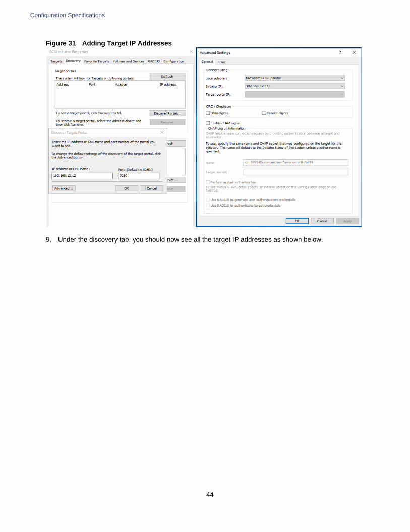
Configuration Specifications
44
Figure 31 Adding Target IP Addresses
9. Under the discovery tab, you should now see all the target IP addresses as shown below.

Configuration Specifications
45
Figure 32 Target IP Address on the iSCSI Initiator
10. Select the target tab. You will see the NetApp device target IQN under Discovered Targets as shown below.

Configuration Specifications
46
Figure 33 Discovered Target Device
11. Click Connect to establish an iSCSI session with the discovered NetApp device. In the Connect to Target di-alog box, select Enable multi-path check box. Click Advanced.
12. In the Advanced Settings dialog box, complete the following steps:
a. On the Local Adapter drop-down list, select Microsoft iSCSI Initiator.
b. On the Initiator IP drop-down list, select the IP address of the host.
c. On the Target Portal IP drop-down list, select the IP of device interface.
d. Click OK to return to the iSCSI Initiator Properties dialog box.
e. Repeat this step for all the initiator and target IPs combination
13. Open the Disk management and initialize and format the disks with NTFS file system and 64K allocation unit size.

Configuration Specifications
47
Figure 34 Disks in Disk-Management
14. Open the Disk management and initialize and format the disks with NTFS file system and 64K allocation unit size.
15. Under Disk Management, right-click the Disk and select Properties.
16. In the NetApp LUN C-Mode Multi-Path Disk Device Properties dialog box, click the MPIO tab. You should see two storage connections being established; one being Active/Optimized and other one is Active/Unoptimized. These represent the path states defined by the SCSI ALUA (Asymmetric Logical Unit Access) protocol, with the Active/Optimized path being the path to the primary storage controller for the LUN and the Ac-tive/Unoptimized being the path to the HA partner controller.

Configuration Specifications
48
Figure 35 NetApp Disk MPIO Settings
17. Install the NetApp Windows Host Utilities package to set all appropriate timeout settings. The host utilities package, along with detailed instructions for installation can be downloaded from the Host Utilities page of the NetApp Support site. This solution was tested using default values, which include lower timeouts than the NetApp recommended values.
Installing SQL Server and Configuration Recommendations
There are many recommendations and best practices guides available for most of SQL Server settings. But relevance of these recommendations may vary from one database deployment to other. It is suggested to thoroughly test and validate critical settings and determine whether or not to implement on the specific database environment. The following sections discuses some of the key aspects of SQL Server installation and configurations, which have been used and tested on the FlexPod system. The rest of SQL Server settings are kept at default and used for performance testing.
SQL Server Installation
For the step-by-step process to install SQL Server 2016 on a Windows Operating system, click here.
On the Server Configuration window of SQL Server installation, make sure that instant file initialization is enabled by enabling check box as shown in Figure 36. This enables the SQL server data files are instantly initialized avowing zeroing operations.

Configuration Specifications
49
Figure 36 Enabling Instance File Initialization During SQL Server Deployment
If the domain account which is used as SQL Server service account is not member of local administrator group, then add SQL Server service account to the “Perform volume maintenance tasks” policy using Local Security Policy editor as shown below.
Figure 37 Granting Volume Maintenance Task Permissions to SQL Server Service Account

Configuration Specifications
50
In the Database Engine Configuration window under the TempDB tab, make sure the number of TempDB data files are equal to 8 when the vCPUs or logical processors of the SQL VM is less than or equal to 8. If the number of logical processors are more than 8, start with 8 data files and try to add data files in the multiple of 4 when the contention is noticed on the TempDB resources. The following diagram shows that there are 8 TempDB files chosen for a SQL virtual machine which has 8 vCPUs. Also, as general best practice, keep the TempDB data and log files are two different volumes.
Figure 38 TempDB Configuration
Lock Pages in Memory
Make sure to add SQL Server service account is added to “Lock Pages in Memory” policy using the Windows Group Policy editor. Granting the Lock Pages in Memory user right to the SQL Server service account prevents SQL Server buffer pool pages from paging out by Windows Server.

Configuration Specifications
51
Figure 39 Adding SQL Server Service Account to Lock Pages in Memory Policy
Max Server Memory Setting
The SQL Server can consume all the memory allocated to the VM. Setting the Maximum Server Memory allows you to reserve sufficient memory for Operating System and other processes running on the VM. Ideally, you should monitor the overall memory consumption of SQL Server under regular business hours and determine the memory requirements. To start, allow the SQL Server to consume about 80 percent of the total memory or leave at least 2-4GB memory for Operating system. The Maximum Server Memory setting can be dynamically adjusted based on the memory requirements.
Number of Data LUNs and Database Data Files
For user databases that have heavy DML operations, it is recommended to create multiple data files of the same size in order to reduce the allocation contention.
If there are high IO demanding workload deployments, use more than one LUN for keeping the database data files. The database performance of such deployments may hit by the queues depths defined at the LUN level both in ESXi environment as well storage level. ONTAP supports a queue depth of 2048 per controller. Queue depths for each client should be configured such that the total possible outstanding commands from all clients does not exceed this limit. For this validation, queue depths were not modified from OS defaults.
For other SQL Server configuration recommendations, refer to the VMware deployment guide for SQL Server here.
NetApp SnapCenter Installation and Configuration
SnapCenter 4.0 Prerequisites
SnapCenter operations on each SQL Server require memory beyond the requirements of the SQL database instances. For SnapCenter processes to operate efficiently, an additional 4GB of memory should be allocated to each SQL Server VM in addition to the memory requirements of the databases and operating system.
Configuration Specifications
52
SnapCenter Server requires at least 4 vCPUs and 8GB RAM. Additional CPU and memory resources can improve performance depending on workload and job schedules. All Microsoft Windows servers should have current patch updates applied.
For this validation, SnapCenter 4.0 was installed and configured per the instructions in the SnapCenter Software 4.0 Installation and Setup Guide. With the exception of site-specific configuration details such as hostnames, IP addresses and database names, no additional changes were made to the default installation process or options.

Solution Performance Testing and Validation
53
Solution Performance Testing and Validation
This section details the solution tests conducted to validate the robustness of the solution. Table 6 lists the complete details of the testbed setup used for conducting various performance tests discussed in the following sections.
Table 6 Hardware and Software Details of Test Bed Configuration
Component Device Details
Compute 1x Cisco UCS 5108 blade chassis with 2x Cisco UCS 2304 IO
Modules
4x Cisco UCS B200 M5 blades each with one Cisco UCS 1340
VIC adapter
Processor Cores per B200 M5 blade 2x Intel® Xeon® Gold 5118 CPUS , 2.3GHz, 16.5MB L3 cache,
12 Cores per CPU
Memory per B200 M5 blade 384GB (12x 32GB DIMMS operating at 2666MHz)
Fabric Interconnects 2x Cisco UCS 3rd
Gen 6332-16UP
Cisco UCS Manager Firmware : 3.2(2d)
Network Switches 2x Cisco Nexus 9000 series switches
Storage Controllers 2x NetApp AFF A300 storage controllers with 36x 800GB SSD
Hypervisor VMWare vSphere 6.5 Update 1
Guest Operating System Windows 2016 Standard Edition
Database software SQL Server 2016 SP1 Enterprise Edition
Performance Test Methodology and Results
The FlexPod system is architected from the ground up to offer great flexibility, scalability and resiliency to cater to various high performance and low latency demanding enterprise workloads such as databases, ERP, CRM and BI system, etc.
In this reference architecture, the FlexPod system is tested and validated with Microsoft SQL Server databases for OLTP (Online Transaction Processing) workloads. Typically, the OLTP workloads are compute intensive and characterized by large number of parallel random reads and writes. The FlexPod system which is built with the combination of Cisco UCS B200 M5 blades powered by the latest Intel scalable processors, 40G Fabric Interconnect and Nexus switches and NetApp All Flash storage, will enable customers to seamlessly consolidate and run many SQL Server databases instances.
This reference architecture aims to demonstrate below three aspects of the FlexPod system by hosting multiple SQL server OLTP-like workloads. The following list provides the tests conducted on the FlexPod system:
Demonstrate database scalability both scale-up and scale-out scenarios using Single Cisco UCS B200 M5 blade and multiple Cisco UCS B200 M5 Blades for database sizes - 1TB and 3TB

Solution Performance Testing and Validation
54
Demonstrate maximum IO capacity of the NetApp AFF A300 storage array
Demonstrate NetApp storage snapshots for data protection and quick recovery of databases.
HammerDB tool is used to simulate OLTP-Like workload at 80:20 read: write ratio on each SQL Server database VM running on the FlexPod system. This tool is installed on a separate client machine and multiple instances of the tool can be started. These multiple instances of the tool are used to stress multiple SQL VMs at the same time. At the end of each test, the tool reports the database performance metrics. The performance of each SQL VM is measured using ‘Transactions Per Minute (TPM)’ reported by the tool.
1TB Database Performance Scalability within Single ESXi Host
The objective of this test is to demonstrate the performance scalability when multiple VMs each with SQL Server databases of 1 TB size, which is typically seen in real-world implementations.
Table 7 lists the virtual machine configuration and database schema details used for this test. Each Virtual Machine is configured with 2 vCPUS and 24GB memory. Dedicated volumes and LUNs are carved out for each VM running single instance of SQL Server. Each SQL VM is stressed about 75 percent of guest CPU utilization generating about 5000 to 5500 total IO operations at 80:20 read: write ratio.
Table 7 Virtual Machine and Database Configuration
Configuration Details
VM Configuration 2 vCPUS, 24GB Memory (20GB allocated for SQL)
Storage Volumes for database 1 x 1.5TB LUN for Data files (2TB volume)
1 x 200GB LUN for T-LOG file (250GB Volume)
1 x 200GB LUN for TempDB files (250GB Volume)
1 x 200GB LUN for SnapInfo files (250GB Volume)
Database SQL Server 2016 SP1 Enterprise Edition
Operating System Windows 2016 Standard Edition
Workload per VM Database Size: 1TB
Targeted total IOPS: 5000 to 5500
Read : Write Ratio: ~80:20
Guest CPU utilization: 70-75%
ESXi Host CPU utilization: 7-8%
Performance Metrics collected:
Transactions Per Minute
Windows Perfmon IO metrics
ESXi ESXTOP metrics

Solution Performance Testing and Validation
55
The graph below shows how multiple SQL Server virtual machines perform on a single ESXi host. In this test, each SQL VM is stressed to generate up to 82,000 Transactions Per Minute (TPM) resulting 600,000 TPMs (approx.) from 8-VMs with 64 percent ESXi host CPU utilization. As we increase the SQL VMs from one to eight, TPM scaled near linear fashion because neither ESXi host CPU nor the underlying storage impose any resource bottleneck.
Figure 40 SQL Server Database Performance Scalability
The graph below shows the disk data transfers (IOPS) and latency details captured using Windows Perfmon tool at Guest OS level for this test. The IOPS scaled linearly with latencies less than 1 millisecond as SQL VMs scaled from one to eight.
0
10
20
30
40
50
60
70
0
100000
200000
300000
400000
500000
600000
700000
1 VM 2 VMs 3 VMs 4 VMs 5 VMs 6 VMs 7 VMs 8 VMs
ESX
i Ho
st C
PU
Uti
lizat
ion
Tran
sact
ion
s P
er
Min
ute
(TP
M)
- O
vera
ll
1TB Database scalability (Single ESXi Host) - TPMs & Host CPU
TPM ESXi Host CPU Utilization

Solution Performance Testing and Validation
56
Figure 41 IOPS Scalability when Consolidating Multiple SQL VMs on Single ESXi Host
The graph below show the NetApp storage system IOPS and CPU utilization for the tests above. As noted in the graph, the storage IOPS scaled near linear fashion as VMs are scaled from one to eight. With eight VMs, the storage controllers are stressed up to 34 percent of CPU utilization only, which clearly indicates that there is enough CPU head room available to take additional workload. The storage IO latencies are stayed less than 0.5 milliseconds for all the above tests.
Figure 42 Storage System IOPS and CPU Utilization During 1TB Single-node Test
1TB Database Performance Scalability Across the ESXi Cluster
The objective of this test is to demonstrate the scalability when multiple SQL VMs deployed across a four-node ESXi cluster, which is typically seen in real-world implementations.
For this multi-hosts ESXi testing, the same Virtual Machine configuration and database schema is used as in the single ESXi Host testing shown in Table 7 .
The graph below shows how multiple SQL Server virtual machines perform on a four node ESXi cluster. In this test, each SQL VM is stressed to generate up to 82,000 Transactions Per Minute (TPM) resulting close to 1 million TPMs (approx.) from 12-VMs with 23 percent ESXi cluster CPU utilization. As we increase the SQL VMs from four
0
0.2
0.4
0.6
0.8
1
1.2
0
5000
10000
15000
20000
25000
30000
35000
40000
45000
1 VM 2 VMs 3 VMs 4 VMs 5 VMs 6 VMs 7 VMs 8 VMs
Avg
IO L
ate
ny
- m
s (G
ue
st O
S)
IOP
S (G
ue
st O
S)
1TB Database scalability (Single ESXi Host) - IOPS & latency
Total IOPS Avg IO Latency(ms)
0
5
10
15
20
25
30
35
40
0
5000
10000
15000
20000
25000
30000
35000
40000
45000
1VM 2VMs 3VMs 4VMs 5VMs 6VMs 7VMs 8VMs
Sto
rage
Co
ntr
olle
r C
PU
uti
lizat
ion
Tota
l IO
PS
(Sto
rage
)
1TB Database scalability (Single ESXi Host) - Storage - IOPS and Controller CPU Utilization
Total IOPs Average CPU Busy

Solution Performance Testing and Validation
57
to twelve, TPM scaled near linear fashion because neither ESXi CPU nor the underlying storage impose any resource bottleneck.
Figure 43 SQL Server Database Performance Scalability on ESXi Cluster
The graph below shows the disk data transfers (IOPS) and latency details captured using Windows Perfmon tool at Guest OS for this test. The IOPS scaled linearly with latencies less than 1 millisecond as SQL VMs scaled from four to twelve.
Figure 44 IOPS Scalability of FlexPod System
The graph below shows that NetApp storage system IOPs and CPU utilization for the tests above. The IOPs scaled near linear fashion as the VMs scaled from four to twelve. With twelve VMs tested, the storage controller’s CPU utilization averaged only 50 percent. The storage latencies for all the above tests are stayed within 0.5 milliseconds. These values indicate that the storage system has not reached the maximum performance threshold and could support additional workloads.
Figure 45 Storage System IOPS and CPU Utilization for 1TB Cluster Test
0
5
10
15
20
25
0
100000
200000
300000
400000
500000
600000
700000
800000
900000
1000000
4 VMs - 1VM per Node 8 VMs - 2VMs per Node 12 VMs - 3VMs per Node
ESX
i Clu
ste
r C
PU
uti
lizat
ion
Tran
sact
ion
Pe
r M
inu
te (
TPM
)
1TB Database scalability (ESXi Cluster) - TPMs & Host CPU
TPM Avg CPU usage of the Cluster
0.93
0.94
0.95
0.96
0.97
0.98
0.99
0
10000
20000
30000
40000
50000
60000
70000
4 VMs - 1VM per Node 8 VMs - 2VMs per Node 12 VMs - 3VMs per Node
Avg
IO L
ate
ny
- m
s (G
ue
st O
S)
Tota
l IO
PS
(Gu
est
)
1TB Database scalability (Across ESXi cluster) - IOPS & latency
Total IOPS Avg IO Latency(ms)
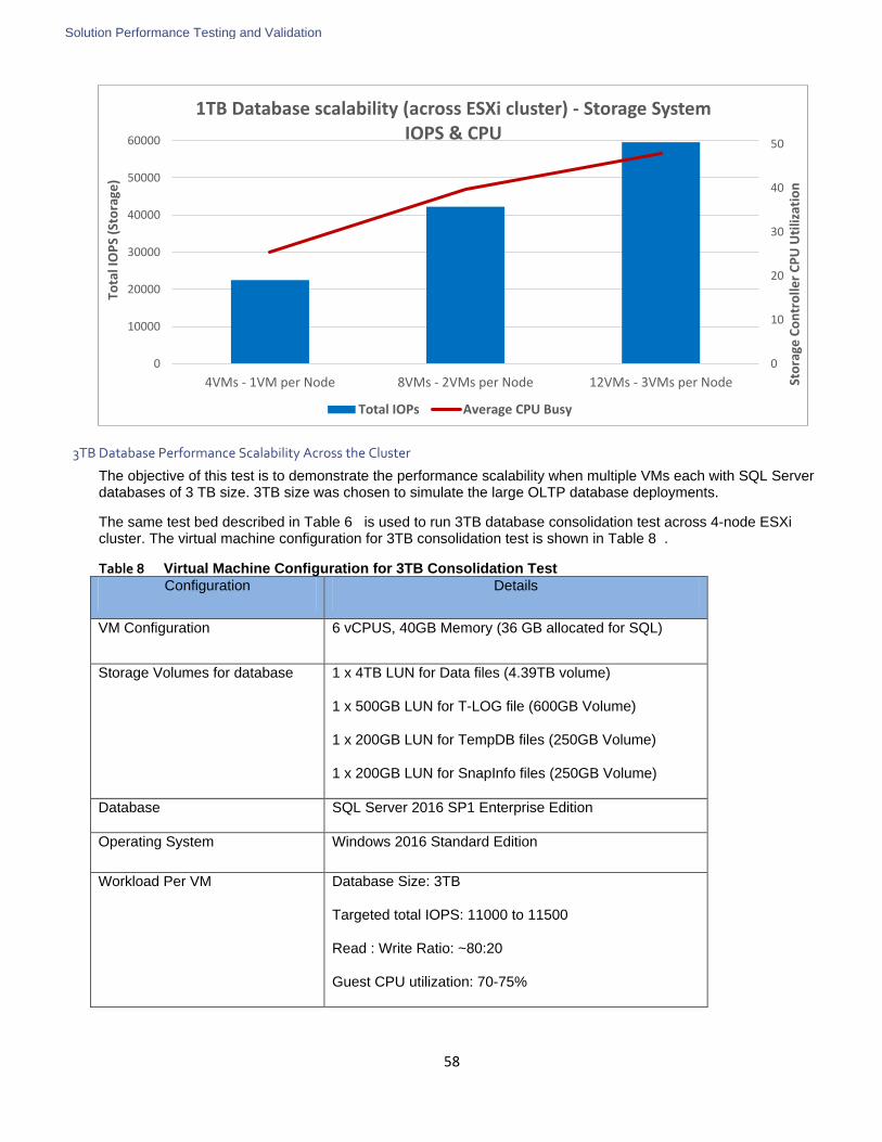
Solution Performance Testing and Validation
58
3TB Database Performance Scalability Across the Cluster
The objective of this test is to demonstrate the performance scalability when multiple VMs each with SQL Server databases of 3 TB size. 3TB size was chosen to simulate the large OLTP database deployments.
The same test bed described in Table 6 is used to run 3TB database consolidation test across 4-node ESXi cluster. The virtual machine configuration for 3TB consolidation test is shown in Table 8 .
Table 8 Virtual Machine Configuration for 3TB Consolidation Test
Configuration Details
VM Configuration 6 vCPUS, 40GB Memory (36 GB allocated for SQL)
Storage Volumes for database 1 x 4TB LUN for Data files (4.39TB volume)
1 x 500GB LUN for T-LOG file (600GB Volume)
1 x 200GB LUN for TempDB files (250GB Volume)
1 x 200GB LUN for SnapInfo files (250GB Volume)
Database SQL Server 2016 SP1 Enterprise Edition
Operating System Windows 2016 Standard Edition
Workload Per VM Database Size: 3TB
Targeted total IOPS: 11000 to 11500
Read : Write Ratio: ~80:20
Guest CPU utilization: 70-75%
0
10
20
30
40
50
0
10000
20000
30000
40000
50000
60000
4VMs - 1VM per Node 8VMs - 2VMs per Node 12VMs - 3VMs per Node Sto
rage
Co
ntr
olle
r C
PU
Uti
lizat
ion
Tota
l IO
PS
(Sto
rage
) 1TB Database scalability (across ESXi cluster) - Storage System
IOPS & CPU
Total IOPs Average CPU Busy

Solution Performance Testing and Validation
59
Configuration Details
Host CPU utilization by each VM : 22%
Performance Metrics collected:
Transactions Per Minute
Windows Perfmon IO metrics
ESXi ESXTOP metrics
The graph below shows how multiple SQL Server virtual machines perform on a four node ESXi cluster. In this test, each SQL VM is stressed to generate up to 125,000 Transactions Per Minute (TPM) resulting close to 1 million TPMs (approx.) from eight-VMs with 43 percent ESXi cluster CPU utilization. As we increase the SQL VMs from one to eight, TPM scaled near linear fashion because neither ESXi CPU nor the underlying storage impose any resource bottleneck.
Figure 46 3TB Database Consolidation on FlexPod System
The graph below shows the disk data transfers (IOPS) and latency details captured using Windows Perfmon tool at Guest OS for this test. The IOPS scaled linearly with latencies less than 2 milliseconds as SQL VMs scaled from one to eight.
This indicates that large working set databases (multiple TB sizes) can be easily consolidated on the FlexPod system built using Cisco UCS B200 M5 blades and NetApp All Flash A300 storage array.
Figure 47 IO Scalability During 3TB DB Consolidation
0
5
10
15
20
25
30
35
40
45
0
100000
200000
300000
400000
500000
600000
700000
800000
900000
1000000
1 VM - Single Node 4VMs - 1VM per Node 8VMs - 2VMs per Node
ESX
i Clu
ste
r C
PU
uti
lizat
ion
Tran
sact
ion
s P
er
Min
ute
(TP
M)
3TB Database scalability (across ESXi cluster) - TPMs & Host CPU
TPM Avg CPU usage of the Cluster

Solution Performance Testing and Validation
60
The graph below show the NetApp storage system IOPs and CPU utilization for the above tests. As shown in the graph, the IOPS scaled near linear fashion as VMs are scaled from one to eight. With eight VMs test across the cluster, storage controller’s CPU utilization averaged roughly 55 percent. The storage latencies are stayed within 1 millisecond. These values indicate that the storage system has not reached the maximum performance threshold and could support additional workloads.
Figure 48 Storage System IOPS and CPU Utilization for 3TB Cluster Test
Maximum IO Capacity of NetApp AFF A300 Storage for SQL Server Workload
The goal of this test is to demonstrate the maximum storage performance that the NetApp AFF A300 storage can deliver for SQL Server database workloads.
During the performance scalability tests discussed in the above sections, the storage subsystem was not stressed to its maximum levels. Hence in order to test and achieve the maximum storage performance, SQL Server memory on each VM has been reduced to 4GB in order to force SQL Server get everything from storage rather than caching the data. Table 9 lists the VM configuring for this test.
0
0.2
0.4
0.6
0.8
1
1.2
1.4
1.6
1.8
0
10000
20000
30000
40000
50000
60000
70000
80000
90000
100000
1 VM - Single Node 4VMs - 1VM per Node 8VMs - 2VMs per Node
Avg
IO L
ate
ny
- m
s (G
ue
st O
S)
IOP
S (G
ue
st O
S)
3TB Database scalability (across ESXi cluster) - IOPS & latency
IOPS Avg IO Latency(ms)
0
10
20
30
40
50
60
0
10000
20000
30000
40000
50000
60000
70000
80000
90000
100000
1VM - Single Node 4VMs - 1VM per Node 8VMs - 2VMs per Node
Sto
rage
Co
ntr
olle
r C
PU
Uti
lizat
ion
IOP
S (S
tora
ge)
Storage System IOPs and CPU Utilization 3TB Cluster test
Total IOPs Average CPU Busy

Solution Performance Testing and Validation
61
Table 9 VM Configuration for Testing Maximum Storage Performance
Configuration Details
VM Configuration 6 vCPUS, 40 GB Memory (4GB GB allocated for SQL)
Storage Volumes for database 1 x 4TB LUN for Data files (4.39TB volume)
1 x 500GB LUN for T-LOG file (600GB Volume)
1 x 200GB LUN for TempDB files (250GB Volume)
1 x 200GB LUN for SnapInfo files (250GB Volume)
Database SQL Server 2016 SP1 Enterprise Edition
Operating System Windows 2016 Standard Edition
Workload Per VM Database Size: 3TB
Targeted total IOPS: ~25,000
Read : Write Ratio: ~85:15
Guest CPU utilization: 70-75%
Host CPU utilization by each VM : 22%
Performance Metrics collected:
Windows Perfmon IO metrics
NetApp storage metrics
The following two graphs show the disk performance metrics captured using Windows Perfmon tool from eight SQL VMs deployed across the four-node ESXi cluster. More than 200,000 IOPS at less than 2ms write latency have been generated by the eight SQL VMs running across the cluster.

Solution Performance Testing and Validation
62
Figure 49 Maximum Storage IOPS
Figure 50 Storage Latencies
The graphs below shows the NetApp storage system performance during the maximum IO test. The total IOPS is over 200,000, with average storage system latency below 1ms is achieved. Storage system CPU averaged over 80 percent, indicating that the storage system is at or near its maximum performance capability. While the system could support additional workload that would drive CPU utilization even higher, but NetApp recommends that storage systems operate below 80 percent utilization during normal operations to prevent significant performance impact during a controller failure scenario.
0
50000
100000
150000
200000
250000IO
PS
(Gu
est
OS)
Maximum IOPS test at <2ms write latency
Total Disk Transfers Total Disk Reads Total Disk Writes
0
1
2
3
Dis
k IO
late
ncy
(m
s) Disk IO Latency : 8-VMs across 4-Node ESXi cluster
Avg Disk Read Latency(ms) Avg Disk Write latency (ms)
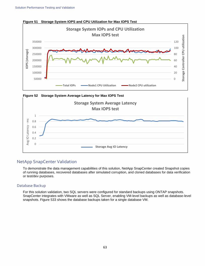
Solution Performance Testing and Validation
63
Figure 51 Storage System IOPS and CPU Utilization for Max IOPS Test
Figure 52 Storage System Average Latency for Max IOPS Test
NetApp SnapCenter Validation
To demonstrate the data management capabilities of this solution, NetApp SnapCenter created Snapshot copies of running databases, recovered databases after simulated corruption, and cloned databases for data verification or test/dev purposes.
Database Backup
For this solution validation, two SQL servers were configured for standard backups using ONTAP snapshots. SnapCenter integrates with VMware as well as SQL Server, enabling VM-level backups as well as database-level snapshots. Figure 533 shows the database backups taken for a single database VM.
0
20
40
60
80
100
120
50000
100000
150000
200000
250000
300000
350000
Sto
rage
Co
ntr
olle
r C
PU
uti
lizat
ion
IOP
S (s
tora
ge)
Storage System IOPs and CPU Utilization Max IOPS test
Total IOPs Node1 CPU Utilization Node2 CPU utilization
0
0.2
0.4
0.6
0.8
1
Avg
IO L
aten
cy -
ms
Storage Avg IO Latency
Storage System Average Latency Max IOPS test

Solution Performance Testing and Validation
64
Figure 53 SQL Server Database Backup using NetApp SnapCenter
Database Cloning
In addition to standard snapshot backups, SnapCenter can create clones of production databases from either an active database or an existing backup snapshot. Cloning of databases provides a means to rapidly provision a copy of production data for further processing in analytics, test, or development environments. Figure 54 shows a clone copy of a single database VM.
Figure 54 SQL Server Database Clone using NetApp SnapCener
Database Restore
SnapCenter 4.0 enables administrators to automatically perform restore operations of specific database files and replay of transaction logs to a specific point it time. This allows granular and time-specific restore of databases without administrative overhead. This is accomplished by using the NORECOVERY option, which simply restores

Solution Performance Testing and Validation
65
the data files but does not replay any existing log files. Once the storage recovery is complete, the database logs from the surviving database instance are replayed to bring the restored copy up to the desired point in time. For this solution validation, a restore operation was performed from a previously taken backup and database operation was confirmed.
Figure 55 shows that a database on SQLVM01 is being restored using a full database backup and then reapplying the transaction log backups one after another until to the point in time mentioned in the screen shot.
Figure 55 Restoring and Recovering SQL Server Database using NetApp SnapCenter
Database restore times can vary significantly depending on several factors including the number of databases per volume, number of databases restored concurrently, and frequency of log backups. Restore operations for the databases used in this validation completed in five minutes or less, which is typical of a configuration with one DB per LUN.
Summary
66
Summary
FlexPod is the optimal shared infrastructure foundation to deploy a variety of IT workloads. It is built on leading computing, networking, storage, and infrastructure software components. This CVD provides detailed production grade Microsoft SQL 2016 deployment supported by industry leaders (Cisco and NetApp) to meet the unique needs of your business.
The performance tests detailed in this document prove the robustness of the solution to host IO sensitive applications like Microsoft SQL Server for database consolidation and/or peak storage IO use cases.

About the Authors
67
About the Authors
Sanjeev Naldurgkar, Cisco Systems, Inc.
Sanjeev Naldurgkar is a Technical Marketing Engineer with Cisco UCS Datacenter Solutions Group. He has been with Cisco for six years focusing on the delivery of customer-driven solutions on Microsoft Hyper-V and VMware vSphere. Sanjeev has over 16 years of experience in the IT Infrastructure, Server virtualization, and Cloud Computing. He holds a Bachelor Degree in Electronics and Communications Engineering, and leading industry certifications from Microsoft and VMware.
Gopu Narasimha Reddy, Cisco Systems, Inc.
Gopu Narasimha Reddy is Technical Marketing Engineer working with Cisco UCS Datacenter Solutions group. He is current focus is Microsoft SQL Server solutions on Microsoft Windows and VMware platforms. His areas of interest include building and validating reference architectures, development of sizing tools in addition to assisting customers in SQL deployments.
David Arnette, NetApp
David Arnette is a Sr. Technical Marketing Engineer for NetApp focused on developing solutions for application deployment on converged infrastructures. He has almost 20 years’ experience designing and implementing storage and virtualization solutions, and holds certifications from NetApp, Cisco, VMware and others. His most recent work is a reference architecture for Virtual Desktop Infrastructure using VMware Horizon on the FlexPod converged infrastructure.
Acknowledgements
The authors would like to thank the following for their contribution to this Cisco Validated Design:
John George, Cisco Systems, Inc.
Pat Sinthusan, NetApp