FlexPod Datacenter with Docker Enterprise Edition for ... · 1 FlexPod Datacenter with Docker...
208
1 FlexPod Datacenter with Docker Enterprise Edition for Container Management Design and Deployment Guide for FlexPod Datacenter with Docker Enterprise Edition for Container Management Last Updated: April 28, 2017
Transcript of FlexPod Datacenter with Docker Enterprise Edition for ... · 1 FlexPod Datacenter with Docker...

1
FlexPod Datacenter with Docker Enterprise
Edition for Container Management Design and Deployment Guide for FlexPod Datacenter with Docker
Enterprise Edition for Container Management Last Updated: April 28, 2017

About the Cisco Validated Design (CVD) Program
The CVD program consists of systems and solutions designed, tested, and documented to facilitate faster,
more reliable, and more predictable customer deployments. For more information visit
http://www.cisco.com/go/designzone.
ALL DESIGNS, SPECIFICATIONS, STATEMENTS, INFORMATION, AND RECOMMENDATIONS
(COLLECTIVELY, "DESIGNS") IN THIS MANUAL ARE PRESENTED "AS IS," WITH ALL FAULTS. CISCO AND
ITS SUPPLIERS DISCLAIM ALL WARRANTIES, INCLUDING, WITHOUT LIMITATION, THE WARRANTY OF
MERCHANTABILITY, FITNESS FOR A PARTICULAR PURPOSE AND NONINFRINGEMENT OR ARISING FROM
A COURSE OF DEALING, USAGE, OR TRADE PRACTICE. IN NO EVENT SHALL CISCO OR ITS SUPPLIERS BE
LIABLE FOR ANY INDIRECT, SPECIAL, CONSEQUENTIAL, OR INCIDENTAL DAMAGES, INCLUDING,
WITHOUT LIMITATION, LOST PROFITS OR LOSS OR DAMAGE TO DATA ARISING OUT OF THE USE OR
INABILITY TO USE THE DESIGNS, EVEN IF CISCO OR ITS SUPPLIERS HAVE BEEN ADVISED OF THE
POSSIBILITY OF SUCH DAMAGES.
THE DESIGNS ARE SUBJECT TO CHANGE WITHOUT NOTICE. USERS ARE SOLELY RESPONSIBLE FOR
THEIR APPLICATION OF THE DESIGNS. THE DESIGNS DO NOT CONSTITUTE THE TECHNICAL OR OTHER
PROFESSIONAL ADVICE OF CISCO, ITS SUPPLIERS OR PARTNERS. USERS SHOULD CONSULT THEIR
OWN TECHNICAL ADVISORS BEFORE IMPLEMENTING THE DESIGNS. RESULTS MAY VARY DEPENDING ON
FACTORS NOT TESTED BY CISCO.
CCDE, CCENT, Cisco Eos, Cisco Lumin, Cisco Nexus, Cisco StadiumVision, Cisco TelePresence, Cisco
WebEx, the Cisco logo, DCE, and Welcome to the Human Network are trademarks; Changing the Way We
Work, Live, Play, and Learn and Cisco Store are service marks; and Access Registrar, Aironet, AsyncOS,
Bringing the Meeting To You, Catalyst, CCDA, CCDP, CCIE, CCIP, CCNA, CCNP, CCSP, CCVP, Cisco, the
Cisco Certified Internetwork Expert logo, Cisco IOS, Cisco Press, Cisco Systems, Cisco Systems Capital, the
Cisco Systems logo, Cisco Unified Computing System (Cisco UCS), Cisco UCS B-Series Blade Servers,
Cisco UCS C-Series Rack Servers, Cisco UCS S-Series Storage Servers, Cisco UCS Manager, Cisco UCS
Management Software, Cisco Unified Fabric, Cisco Application Centric Infrastructure, Cisco Nexus 9000
Series, Cisco Nexus 7000 Series. Cisco Prime Data Center Network Manager, Cisco NX-OS Software, Cisco
MDS Series, Cisco Unity, Collaboration Without Limitation, EtherFast, EtherSwitch, Event Center, Fast Step,
Follow Me Browsing, FormShare, GigaDrive, HomeLink, Internet Quotient, IOS, iPhone, iQuick Study,
LightStream, Linksys, MediaTone, MeetingPlace, MeetingPlace Chime Sound, MGX, Networkers, Networking
Academy, Network Registrar, PCNow, PIX, PowerPanels, ProConnect, ScriptShare, SenderBase, SMARTnet,
Spectrum Expert, StackWise, The Fastest Way to Increase Your Internet Quotient, TransPath, WebEx, and
the WebEx logo are registered trademarks of Cisco Systems, Inc. and/or its affiliates in the United States and
certain other countries.
All other trademarks mentioned in this document or website are the property of their respective owners. The
use of the word partner does not imply a partnership relationship between Cisco and any other company.
(0809R)
© 2017 Cisco Systems, Inc. All rights reserved.

Table of Contents
Executive Summary ................................................................................................................................................................. 8
Business Challenges ............................................................................................................................................................ 9
FlexPod System Overview ................................................................................................................................................... 9
FlexPod Benefits ............................................................................................................................................................ 10
FlexPod: Cisco and NetApp Verified Architecture .......................................................................................................... 10
FlexPod Design Principles ............................................................................................................................................. 11
Implementation Overview .................................................................................................................................................. 11
Highlights .......................................................................................................................................................................... 11
Solution Benefits ................................................................................................................................................................ 12
Audience ........................................................................................................................................................................... 12
Purpose of the Document .................................................................................................................................................. 13
Solution Overview .................................................................................................................................................................. 14
Solution Components ........................................................................................................................................................ 15
Technology Overview ............................................................................................................................................................ 16
Cisco Unified Computing System ....................................................................................................................................... 16
Cisco UCS Manager ...................................................................................................................................................... 17
Cisco UCS Fabric Interconnects .................................................................................................................................... 17
Cisco UCS 5108 Blade Server Chassis .......................................................................................................................... 17
Cisco UCS B200M4 Blade Server .................................................................................................................................. 18
Cisco UCS Fabric Extenders .......................................................................................................................................... 18
Cisco VIC Interface Cards .............................................................................................................................................. 18
Cisco UCS Differentiators .............................................................................................................................................. 18
Cisco Nexus 9000 Switches .............................................................................................................................................. 20
NetApp Storage Controllers ............................................................................................................................................... 20
NetApp All Flash FAS .................................................................................................................................................... 21
NetApp Data ONTAP ......................................................................................................................................................... 21
NetApp Storage Virtual Machines ...................................................................................................................................... 22
NetApp Docker Volume Plugin (nDVP): .............................................................................................................................. 22
Storage Design practices: .................................................................................................................................................. 22
Docker Enterprise Edition ................................................................................................................................................... 23
Docker EE ...................................................................................................................................................................... 25
Docker UCP ................................................................................................................................................................... 25
Docker Trusted Registry ................................................................................................................................................ 28

Solution Design ...................................................................................................................................................................... 31
Architectural Overview ....................................................................................................................................................... 31
Solution Deployment .............................................................................................................................................................. 33
Physical Topology .......................................................................................................................................................... 33
Deployment Hardware and Software ..................................................................................................................................... 34
Deployment Hardware ....................................................................................................................................................... 34
Software Revisions ............................................................................................................................................................ 34
Configuration Guidelines .................................................................................................................................................... 35
Physical Infrastructure ........................................................................................................................................................ 36
FlexPod Cabling ............................................................................................................................................................ 36
FlexPod Cisco Nexus Base ................................................................................................................................................ 40
Set Up Initial Configuration ............................................................................................................................................ 40
FlexPod Cisco Nexus Switch Configuration ........................................................................................................................ 42
Enable Licenses ............................................................................................................................................................. 42
Set Global Configurations .............................................................................................................................................. 43
Create VLANs ................................................................................................................................................................ 43
Add NTP Distribution Interface ....................................................................................................................................... 44
Add Individual Port Descriptions for Troubleshooting ..................................................................................................... 44
Create Port Channels ..................................................................................................................................................... 46
Configure Port Channel Parameters ............................................................................................................................... 47
Configure Virtual Port Channels ..................................................................................................................................... 48
Uplink into Existing Network Infrastructure ..................................................................................................................... 50
NetApp Storage Configuration ........................................................................................................................................... 50
NetApp Hardware Universe ........................................................................................................................................... 50
Controllers ..................................................................................................................................................................... 50
Disk Shelves .................................................................................................................................................................. 50
ONTAP 9.0 ........................................................................................................................................................................ 51
Complete Configuration Worksheet ............................................................................................................................... 51
Configure ONTAP Nodes ............................................................................................................................................... 51
Log In to the Cluster ...................................................................................................................................................... 63
Zero All Spare Disks ...................................................................................................................................................... 63
Set Onboard Unified Target Adapter 2 Port Personality ................................................................................................. 64
Set Auto-Revert on Cluster Management ...................................................................................................................... 65
Set Up Management Broadcast Domain ........................................................................................................................ 65
Set Up Service Processor Network Interface ................................................................................................................. 65

Create Aggregates ........................................................................................................................................................ 65
Verify Storage Failover ................................................................................................................................................... 66
Disable Flow Control on 10GE Ports .............................................................................................................................. 67
Disable Unused FCoE Capability on CNA Ports .............................................................................................................. 67
Configure Network Time Protocol .................................................................................................................................. 68
Configure Simple Network Management Protocol .......................................................................................................... 68
Configure AutoSupport .................................................................................................................................................. 69
Enable Cisco Discovery Protocol ................................................................................................................................... 69
Create Broadcast Domains in Data ONTAP .................................................................................................................... 69
Create Interface Groups ................................................................................................................................................ 69
Create VLANs ................................................................................................................................................................ 69
Create Docker Infrastructure Storage Virtual Machine .................................................................................................... 70
Create Load-Sharing Mirrors of SVM Root Volume ........................................................................................................ 70
Create Block Protocol (FC) Service ................................................................................................................................ 71
Configure HTTPS Access .............................................................................................................................................. 71
Configure NFSv3 ........................................................................................................................................................... 72
Create FlexVol Volumes ................................................................................................................................................. 72
Create Boot LUNs .......................................................................................................................................................... 72
Create Docker Data LUNs .............................................................................................................................................. 73
Schedule Deduplication ................................................................................................................................................. 74
Create FCP LIFs ............................................................................................................................................................. 74
Create NFS LIFs ............................................................................................................................................................. 74
Add Infrastructure SVM Administrator ............................................................................................................................ 75
Create Broadcast Domain for Container Tenant A .......................................................................................................... 75
Create VLAN Interfaces for Container Tenant A ............................................................................................................. 75
Create Docker Tenant Storage Virtual Machine .............................................................................................................. 75
Create Load-Sharing Mirrors of Tenant SVM Root Volume ............................................................................................ 76
Configure Secure Access to Cntr-TNT-A-SVM ............................................................................................................. 76
Configure NFSv3 in Cntr-TNT-A-SVM ........................................................................................................................... 77
Create NFS LIFs in Cntr-TNT-A-SVM ............................................................................................................................ 78
Add Cntr-TNT-A-SVM Administrator and NetApp Volume Plugin (nDVP) User .............................................................. 78
Cisco UCS Direct Storage Connect Base Configuration ..................................................................................................... 79
Perform Initial Setup of Cisco 6248UP Fabric Interconnects for FlexPod Environments .................................................. 79
Cisco UCS Direct Storaqe Connect Setup ..................................................................................................................... 81
Upgrade Cisco UCS Manager Software to Version 3.1(2f) ............................................................................................. 81

Anonymous Reporting ................................................................................................................................................... 81
Configure Cisco UCS Call Home .................................................................................................................................... 82
Place UCS Fabric Interconnects in Fiber Channel Switching Mode ................................................................................ 82
Configure Unified Ports .................................................................................................................................................. 83
Add Block of IP Addresses for KVM Access .................................................................................................................. 85
Synchronize Cisco UCS to NTP ...................................................................................................................................... 85
Edit Chassis Discovery Policy ........................................................................................................................................ 87
Enable Server and Uplink Ports ...................................................................................................................................... 87
Acknowledge Cisco UCS Chassis .................................................................................................................................. 88
Create Uplink Port Channels to Cisco Nexus Switches .................................................................................................. 89
Create a WWNN Pool for FC Boot .................................................................................................................................. 90
Create WWPN Pools ...................................................................................................................................................... 92
Create Storage VSANs .................................................................................................................................................. 95
Assign VSANs to FC Storage Ports ................................................................................................................................ 97
Create vHBA Templates ................................................................................................................................................ 98
Create SAN Connectivity Policy ................................................................................................................................... 100
Create MAC Address Pools ......................................................................................................................................... 102
Create UUID Suffix Pool ............................................................................................................................................... 104
Create Server Pool ...................................................................................................................................................... 105
Create VLANs .............................................................................................................................................................. 105
Modify Default Host Firmware Package ....................................................................................................................... 107
Set Jumbo Frames in Cisco UCS Fabric ....................................................................................................................... 108
Create Local Disk Configuration Policy (Optional) ........................................................................................................ 109
Create Network Control Policy for Cisco Discovery Protocol (CDP) and Link Layer Discovery Protocol (LLDP) ............ 110
Create Power Control Policy ........................................................................................................................................ 111
Create Server Pool Qualification Policy (Optional) ........................................................................................................ 112
Create Server BIOS Policy ........................................................................................................................................... 113
Update the Default Maintenance Policy ........................................................................................................................ 116
Create vNIC Templates ................................................................................................................................................ 117
Create LAN Connectivity Policy ................................................................................................................................... 121
Create Boot Policy (FC Boot) ....................................................................................................................................... 123
Create Service Profile Template (FC Boot) ................................................................................................................... 126
Create Service Profiles ................................................................................................................................................ 133
Gather Necessary Information ...................................................................................................................................... 134
Data ONTAP SAN Storage Setup ..................................................................................................................................... 136

Create Igroups ............................................................................................................................................................. 136
Map LUNs to igroups ................................................................................................................................................... 137
Installation of Red Hat Enterprise Linux Operating System ........................................................................................... 138
Docker Enterprise Edition Installation ............................................................................................................................... 154
Complete Host Networking Setup ................................................................................................................................ 155
Registering Nodes and Updating Host OS ................................................................................................................... 158
Installing and Configuring Ansible ................................................................................................................................ 158
Installing NTP & Configuring Host OS System Clocks .................................................................................................. 163
Installing Cisco Virtual Interface Card (VIC) eNIC (Ethernet Network Interface Card) and fNIC Driver ........................... 165
Configuring Host OS Firewall for required ports ........................................................................................................... 166
Installation of Docker Repo and Docker Engine ............................................................................................................ 168
Configuring Docker CS Engine for Device-Mapper Driver in Direct LVM-Mode ............................................................ 169
Install and Configure Docker UCP Controller Nodes ..................................................................................................... 173
Add UCP Replicas ....................................................................................................................................................... 174
Add UCP Nodes .......................................................................................................................................................... 175
Install and Configure DTR and its Replicas ................................................................................................................... 176
Configure NetApp Docker Volume Plugin (nDVP) ......................................................................................................... 179
Validate Docker UCP and DTR Cluster ......................................................................................................................... 184
Solution Validation ............................................................................................................................................................... 186
Application Container Deployment ................................................................................................................................... 186
Container Networks ......................................................................................................................................................... 188
Deploying container/application container using overlay network ................................................................................ 190
DTR Operations ............................................................................................................................................................... 196
Showing Container Survivability Using Docker Swarm ..................................................................................................... 198
Storage Utilization using a non-admin DDE User .............................................................................................................. 201
Summary ............................................................................................................................................................................. 206
About Authors ..................................................................................................................................................................... 207
Acknowledgements ......................................................................................................................................................... 207

Executive Summary
8
Executive Summary
Docker platform for developers and IT operations to build, ship, and
run distributed applications anywhere. With Microservices architecture shaping the next generation of IT,
enterprises with large investments in monolithic applications are finding ways to adopt Docker as a strategy
for modernizing their application architectures and keeping the organization competitive and cost effective.
Containerization provides the agility, control, and portability that developers and IT operations require to
build and deploy applications across any infrastructure. The Docker platform allows distributed applications
to be easily composed into a lightweight application container that can change dynamically yet non-
disruptively. This capability makes the applications portable across development, test, and production
environments running on physical or virtual machines locally, in data centres, and across the networks of
different cloud service providers.
Cisco Unified Computing System (UCS) is a next-generation Datacenter platform that unifies computing,
networking, storage access, and virtualization into a single cohesive system, which makes Cisco UCS an
ideal platform for Docker Enterprise Edition
In FlexPod with Docker Enterprise Edition, NetApp Docker Volume Plugin (nDVP) provides direct integration
with the Docker ecosystem for NetApp's ONTAP, E-Series, and SolidFire storage platforms. The nDVP
package supports the provisioning and management of storage resources from the storage platform to
Docker hosts, with a robust framework for adding additional platforms in the future.
Figure 1. FlexPod Component Families

Business Challenges
Technological revolution has created new opportunities and challenges for businesses in this digital world.
Many companies small and big, new and old are using disruptive innovations such as Microservices
architecture to quickly develop and deploy applications and services to rapidly adopt to changing markets
and meet customer needs. These innovations also provide a path to modernize traditional business critical
applications providing agility, flexibility and portability to reduce operational and management costs while
improving performance and security. In order to keep up with new technologies or stay one step ahead,
enterprises will have to overcome key challenges to accelerate product development, add value and
compete better at lower cost.
Key Challenges:
Portability: Applications have dependencies around OS versions, libraries, Java versions, etc. Any
changes to these dependencies can break portability which means applications developed on a
specific environment may behave differently on a production environment hosted on-premise or
cloud. Changing code and rebuilding/testing code leads to delay in product or service offering and
loss of market share.
Agility: Enterprises have many legacy applications, tools and complex development process slowing
innovation significantly as product release cycle takes days to weeks due to complex flow from
development to production.
Resource Utilization: Engineering and hardware resources in large enterprises are not used
efficiently due to various organizations operating in silos. These silos that worked in the past are
causing a huge overhead in development/release cycle and resource under-utilization as technology
changes rapidly.
Policy Management: Large enterprises have redundant processes and policies in place, and are
reluctant to adopt new technologies due to fear of breaking compliance causing delays in new
development/release cycle.
FlexPod System Overview
FlexPod is a best practice Datacenter architecture that includes these components:
Cisco Unified Computing System (Cisco UCS)
Cisco Nexus switches
NetApp fabric-attached storage (FAS), AFF, and/or NetApp E-Series storage systems
These components are connected and configured according to best practices of both Cisco and NetApp,
and provide the ideal platform for running a variety of enterprise workloads with confidence. As previously
mentioned, the reference architecture covered in this document leverages the Cisco Nexus 9000 Series
switch. One of the key benefits of FlexPod is the ability to maintain consistency at scaling, including scale up
and scale out. Each of the component families shown in Figure 1 (Cisco Unified Computing System, Cisco
Nexus, and NetApp storage systems) offers platform and resource options to scale the infrastructure up or
down, while supporting the same features and functionality that are required under the configuration and
connectivity best practices of FlexPod.

FlexPod Benefits
As customers transition toward shared infrastructure or cloud computing they face a number of challenges
such as initial transition hiccups, return on investment (ROI) analysis, infrastructure management and future
growth plan. The FlexPod architecture is designed to help with proven guidance and measurable value. By
introducing standardization, FlexPod helps customers mitigate the risk and uncertainty involved in planning,
designing, and implementing a new Datacenter infrastructure. The result is a more predictive and adaptable
architecture capable of meeting and exceeding customers' IT demands.
FlexPod: Cisco and NetApp Verified Architecture
Cisco and NetApp have thoroughly validated and verified the FlexPod solution architecture and its many use
cases while creating a portfolio of detailed documentation, information, and references to assist customers
in transforming their Datacenters to this shared infrastructure model. This portfolio includes, but is not limited
to the following items:
Best practice architectural design
Workload sizing and scaling guidance
Implementation and deployment instructions
Technical specifications (rules for FlexPod
Frequently asked questions (FAQs)
Cisco Validated Designs (CVDs) and NetApp Verified Architectures (NVAs) focused on a variety of
use cases
Cisco and NetApp have also built a robust and experienced support team focused on FlexPod solutions,
from customer account and technical sales representatives to professional services and technical support
engineers. The Co-operative Support Program by NetApp and Cisco, customers and channel service
partners with direct access to technical experts who collaborate with cross vendors and have access to
shared lab resources to resolve potential issues. FlexPod supports tight integration with virtualized and cloud
infrastructures, making it a logical choice for long-term investment. The following IT initiatives are addressed
by the FlexPod solution.
Integrated System
FlexPod is a pre-validated infrastructure that brings together compute, storage, and network to simplify,
accelerate, and minimize the risk associated with Datacenter builds and application rollouts. These
integrated systems provide a standardized approach in the Datacenter that facilitates staff expertise,
application onboarding, and automation as well as operational efficiencies relating to compliance and
certification.
Out of the Box Infrastructure High Availability
FlexPod is a highly available and scalable infrastructure that IT can evolve over time to support multiple
physical and virtual application workloads. FlexPod has no single point of failure at any level, from the server
through the network, to the storage. The fabric is fully redundant and scalable, and provides seamless traffic
failover, should any individual component fail at the physical or virtual layer.

FlexPod Design Principles
FlexPod addresses four primary design principles:
Application availability: Makes sure that services are accessible and ready to use.
Scalability: Addresses increasing demands with appropriate resources.
Flexibility: Provides new services or recovers resources without requiring infrastructure
modifications.
Manageability: Facilitates efficient infrastructure operations through open standards and APIs.
Implementation Overview
Docker Enterprise Edition solution is integrated and validated on Cisco UCS is implemented on Cisco UCS B-
Series server and Cisco Nexus platforms. The NetApp AFF 8040 storage system is integrated with Docker EE
using the NetApp Docker Volume Plugin (nDVP) to provide persistent storage for containers via NFS. Another
NFS volume is mounted on all Docker Trusted Registry(DTR) nodes for storing Docker images in a private
and on-prem trusted repository. To enable stateless computing boot LUNs are provisioned from the NetApp
storage using Fibre Channel, and additional Fibre Channel LUNs are provisioned for container and image
storage management (graph).
The architecture covers step by step install/configuration, provisioning process, and the solution testing
required for CVD. The bare metal is installed manually; OS configuration and Docker EE install is automated
through built-in Docker tools and Ansible. The end-to-end stack is tested for correctness (recommended
software stack), performance, and scalability, high-availability and security policies. The containers will be
deployed and managed by Docker (Universal Control Plane) UCP. This deployment guide contains detailed
step by step instructions on setting up the complete stack and solution validation test results.
Highlights
Industry-Leading Converged Computing Infrastructure: Cisco UCS blade servers enable
customers to rapidly and efficiently deploy and manage compute, network and storage functions for
containers. They enable customers to reduce IT costs through consolidation, manage more
containers per computing node and make better use of infrastructure to provide an application
container environment in real time.
Industry-Leading Container Application Infrastructure: Docker EE brings container orchestration,
management and security to the enterprise. It enables developers and system administrators to
build, ship and run distributed applications anywhere.
Combined Use Cases
Microservice and cloud native application architecture: Enables stateless application
container deployment for specific business use needs
Continuous integration and continuous deployment(CI/CD): Enable developers to develop
and test applications more quickly and within relevant environment
DevOps: Break down barriers between development and operations teams to improve
delivery of applications for the business

Big Data: Empower organizations to use big data analytics using small foot print applications at a
very large scale numbers
Infrastructure optimization: Decrease infrastructure costs while increasing efficiency. The
lightweight nature of containers and the absence of hypervisors and guest operating systems
enables enterprises to optimize resource and eliminate licensing costs
Solution Benefits
The benefits of Docker Enterprise Edition on FlexPod include the following:
Cisco UCS
Simplicity: Reduced Datacenter complexities through Cisco UCS converged infrastructure
with a single management control plane for hardware lifecycle management
Rapid Deployment: Easily deploy and scale the solution
High Availability: Superior scalability and high-availability
Faster ROI: Better response with optimal ROI
NetApp ONTAP
Ease of deployment: Simplified deployment and management across flash, disk, and cloud
Flexibility: Fast and agile solution deployment
Security: Data protection with flexible, built-in encryption
Performance: Leading TCO with flash efficiencies, performance, and scale.
Docker Enterprise Edition
Agility: Gain the freedom to define environments and create and deploy applications quickly
and easily, providing flexibility of IT operations that respond quickly to change
Control: Enable developers to own the code from the infrastructure to the application and
quickly move from the build to the production environment. IT operations manageability
features enable organizations to standardize, secure, and scale the operating environment
Portability: Docker Containers are self-contained and independent units that are portable
between private infrastructure and public cloud environments without complexity or
disruption
Security: Docker EE makes safer applications with usable security features with end to end
encryption, integrated secrets management, image signing, and vulnerability monitoring
Audience
The audience for this document includes, but is not limited to, sales engineers, field consultants, professional
services, IT managers, partner engineers, IT architects, and customers who want to take advantage of an
infrastructure that is built to deliver IT efficiency and enable IT innovation. The reader of this document is

expected to have the necessary training and background to install and configure Red Hat Enterprise Linux,
Cisco Unified Computing System (UCS) and Cisco Nexus Switches, NetApp storage as well as high level
understanding of Docker Container components. External references are provided where applicable and it is
recommended that the reader be familiar with these documents.
Readers are also expected to be familiar with the infrastructure, network and security policies of the
customer installation.
Purpose of the Document
This document highlights the benefits of using Docker Enterprise Edition (EE) on FlexPod comprising of Cisco
UCS infrastructure and NetApp ONTAP storage backend to efficiently deploy, scale, and manage a
production-ready application container environment for enterprise customers. The goal of this document is
to demonstrate the value that Cisco UCS brings to the data center, such as single-point hardware lifecycle
management and highly available converged compute and network infrastructure for application container
deployments using Docker EE.

Solution Overview
FlexPod solutions speed up IT operations today and create the modern technology foundation you need for
initiatives like private cloud, big data, and desktop virtualization. With Cisco UCS Manager and Cisco Single
Connect Technology, hardware is automatically configured by application-centric policies ushering in a new
era of speed, consistency, and simplicity for Datacenter operations. UCS brings the flexibility of virtualized
systems to the physical world in a way no other server architecture can, lowering costs and improving your
ROI.
Leveraging the centralized management of Cisco UCS Manager, this solution provides unified, embedded,
policy-driven management to programmatically control server, network, and storage resources you can
efficiently manage the scale-up/ -out infrastructure. Furthermore, Cisco Nexus - unified Fabric is a holistic
network architecture comprising switching, security, and services that are designed for physical, virtual, and
cloud environments. It uniquely integrates with servers, storage, and orchestration platforms for more
efficient operations and greater scalability.
Cisco has partnered with Docker to provide Container Management solution to accelerate the IT
transformation by enabling easy and faster deployments, greater flexibility of choice, business agility,
efficiency, lower risk.
Docker has become the industry standard for developers and IT operations to build, ship and run distributed
applications in bare-metal, virtualized and cloud environments. As organizations adopt public, private or
Hybrid cloud, Docker makes it easy to move applications between on premise and cloud environments.
Docker can significantly improve hardware resource utilization, accelerate application lifecycle and reduce
overall cost by automating IT processes, and deploying dockerized application on-premise or cloud
environment.
Docker EE delivers an integrated platform for developers and IT operations to collaborate in the enterprise
software supply chain. Bringing security, policy and controls to the application lifecycle without sacrificing
any agility or application portability. Docker EE integrates to enterprise business from on-premises and
VPC deployment models, open APIs and interfaces, to flexibility for supporting a wide variety of workflows.

Figure 2. Docker Enterprise Edition Software Supply Chain Journey to CaaS
Solution Components
The solution offers redundant architecture from a compute, network, and storage perspective. The solution
consists of the following key components:
Cisco Unified Computing System (UCS)
Cisco UCS Manager
Cisco UCS 6248UP Fabric Interconnects
Cisco 2204XP IO Module or Cisco UCS Fabric Extenders
Cisco B200 M4 Servers
Cisco VIC 1340
Cisco Nexus 93180YC-EX Switches
Docker Enterprise Edition (EE)
Docker EE (Basic)
Docker Universal Control Plane (UCP)
Docker Trusted Repository (DTR)
Red Hat Enterprise Linux 7.3
NetApp AFF8040

Technology Overview
This section provides a brief introduction of the various hardware/ software components used in this
solution.
Cisco Unified Computing System
The Cisco Unified Computing System is a next-generation solution for blade and rack server computing. The
system integrates a low-latency; lossless 10 Gigabit Ethernet unified network fabric with enterprise-class,
x86-architecture servers. The system is an integrated, scalable, multi-chassis platform in which all resources
participate in a unified management domain. The Cisco Unified Computing System accelerates the delivery
of new services simply, reliably, and securely through end-to-end provisioning and migration support for
both virtualized and non-virtualized systems. Cisco Unified Computing System provides:
Comprehensive Management
Radical Simplification
High Performance
The Cisco Unified Computing System consists of the following components:
Compute - The system is based on an entirely new class of computing system that incorporates
rack mount and blade servers based on Intel Xeon 2600 v3 Series Processors.
Network - The system is integrated onto a low-latency, lossless, 10-Gbps unified network fabric.
and high-performance computing networks which are separate networks today. The unified fabric
lowers costs by reducing the number of network adapters, switches, and cables, and by decreasing
the power and cooling requirements.
Virtualization - The system unleashes the full potential of virtualization by enhancing the scalability,
performance, and operational control of virtual environments. Cisco security, policy enforcement, and
diagnostic features are now extended into virtualized environments to better support changing
business and IT requirements.
Storage access - The system provides consolidated access to both SAN storage and Network
Attached Storage (NAS) over the unified fabric. It is also an ideal system for Software defined
Storage (SDS). Combining the benefits of single framework to manage both the compute and
Storage servers in a single pane, Quality of Service (QOS) can be implemented if needed to inject IO
throttling in the system. In addition, the server administrators can pre-assign storage-access policies
to storage resources, for simplified storage connectivity and management leading to increased
productivity.
Management - the system uniquely integrates all system components to enable the entire solution
to be managed as a single entity by the Cisco UCS Manager. The Cisco UCS Manager has an
intuitive graphical user interface (GUI), a command-line interface (CLI), and a powerful scripting
library module for Microsoft PowerShell built on a robust application programming interface (API) to
manage all system configuration and operations.

Cisco Unified Computing System (Cisco UCS) fuses access layer networking and servers. This high-
performance, next-generation server system provides a data center with a high degree of workload agility
and scalability.
Cisco UCS Manager
Cisco Unified Computing System (UCS) Manager provides unified, embedded management for all software
and hardware components in the Cisco UCS. Using Single Connect technology, it manages, controls, and
administers multiple chassis for thousands of virtual machines. Administrators use the software to manage
the entire Cisco Unified Computing System as a single logical entity through an intuitive GUI, a command-
line interface (CLI), or an XML API. The Cisco UCS Manager resides on a pair of Cisco UCS 6200 Series
Fabric Interconnects using a clustered, active-standby configuration for high-availability.
UCS Manager offers unified embedded management interface that integrates server, network, and storage.
UCS Manager performs auto-discovery to detect inventory, manage, and provision system components that
are added or changed. It offers comprehensive set of XML API for third part integration, exposes 9000
points of integration and facilitates custom development for automation, orchestration, and to achieve new
levels of system visibility and control.
Service profiles benefit both virtualized and non-virtualized environments and increase the mobility of non-
virtualized servers, such as when moving workloads from server to server or taking a server offline for
service or upgrade. Profiles can also be used in conjunction with virtualization clusters to bring new
resources online easily, complementing existing virtual machine mobility.
For more Cisco UCS Manager Information, refer to: http://www.cisco.com/c/en/us/products/servers-
unified-computing/ucs-manager/index.html
Cisco UCS Fabric Interconnects
The Fabric interconnects provide a single point for connectivity and management for the entire system.
Typically deployed as an active-
single, highly-available management domain controlled by Cisco UCS Manager. The fabric interconnects
manage all I/O efficiently and securely at a single point, resulting in deterministic I/O latency regardless of a
-Gbps unified fabric with low-latency,
lossless, cut-through switching that supports IP, storage, and management traffic using a single set of
cables. The fabric interconnects feature virtual interfaces that terminate both physical and virtual connections
equivalently, establishing a virtualization-aware environment in which blade, rack servers, and virtual
machines are interconnected using the same mechanisms. The Cisco UCS 6248UP is a 1-RU Fabric
Interconnect that features up to 48 universal ports that can support 80 Gigabit Ethernet, Fiber Channel over
Ethernet, or native Fiber Channel connectivity.
For more information, visit the following link: http://www.cisco.com/c/en/us/products/servers-unified-
computing/ucs-6200-series-fabric-interconnects/index.html
Cisco UCS 5108 Blade Server Chassis
The Cisco UCS 5100 Series Blade Server Chassis is a crucial building block of the Cisco Unified Computing
System, delivering a scalable and flexible blade server chassis. The Cisco UCS 5108 Blade Server Chassis is
six rack units (6RU) high and can mount in an industry-standard 19-inch rack. A single chassis can house up
to eight half-width Cisco UCS B-Series Blade Servers and can accommodate both half-width and full-width

blade form factors. Four single-phase, hot-swappable power supplies are accessible from the front of the
chassis. These power supplies are 92 percent efficient and can be configured to support non-redundant, N+
1 redundant and grid-redundant configurations. The rear of the chassis contains eight hot-swappable fans,
four power connectors (one per power supply), and two I/O bays for Cisco UCS 2204XP or 2208XP Fabric
Extenders. A passive mid-plane provides up to 40 Gbps of I/O bandwidth per server slot and up to 80 Gbps
of I/O bandwidth for two slots. The chassis is capable of supporting future 80 Gigabit Ethernet standards.
For more information, please refer to the following link: http://www.cisco.com/c/en/us/products/servers-
unified-computing/ucs-5100-series-blade-server-chassis/index.html
Cisco UCS B200M4 Blade Server
The enterprise-
System portfolio in a half-width blade form factor. The Cisco UCS B200 M4 uses the power of the latest
Intel® Xeon® E5-2600 v3 Series processor family CPUs with up to 768 GB of RAM (using 32 GB DIMMs),
two solid-state drives (SSDs) or hard disk drives (HDDs), and up to 80 Gbps throughput connectivity. The
UCS B200 M4 Blade Server mounts in a Cisco UCS 5100 Series blade server chassis or UCS Mini blade
server chassis. It has 24 total slots for registered ECC DIMMs (RDIMMs) or load-reduced DIMMs (LR DIMMs)
for up to 768 GB total memory capacity (B200 M4 configured with two CPUs using 32 GB DIMMs). It
ter, which provides Ethernet and FCoE.
For more information, see: http://www.cisco.com/c/en/us/products/servers-unified-computing/ucs-b200-
m4-blade-server/index.html
Cisco UCS Fabric Extenders
The Cisco UCS 2204XP Fabric Extender has four 10 Gigabit Ethernet, FCoE-capable, SFP+ ports that
connect the blade chassis to the fabric interconnect. Each Cisco UCS 2204XP has sixteen 10 Gigabit
Ethernet ports connected through the mid-plane to each half-width slot in the chassis. Typically configured
in pairs for redundancy, two fabric extenders provide up to 80 Gbps of I/O to the chassis.
Cisco VIC Interface Cards
The Cisco UCS Virtual Interface Card (VIC) 1340 is a 2-port 40-Gbps Ethernet or dual 4 x 10-Gbps Ethernet,
Fiber Channel over Ethernet (FCoE) capable modular LAN on motherboard (mLOM) designed exclusively for
the M4 generation of Cisco UCS B-Series Blade Servers.
All the blade servers for both Controllers and Computes will have MLOM VIC 1340 card. Each blade will have
a capacity of 40 Gb of network traffic. The underlying network interfaces like will share this MLOM card.
The Cisco UCS VIC 1340 enables a policy-based, stateless, agile server infrastructure that can present over
256 PCIe standards-compliant interfaces to the host that can be dynamically configured as either network
interface cards (NICs) or host bus adapters (HBAs).
For more information, see:
http://www.cisco.com/c/en/us/products/interfaces-modules/ucs-virtual-interface-card-1340/index.html
Cisco UCS Differentiators
-center. Following
are the unique differentiators of UCS and UCS Manager:

1. Embedded Management In UCS, the servers are managed by the embedded firmware in the
Fabric Interconnects, eliminating need for any external physical or virtual devices to manage the
servers.
2. Unified Fabric In UCS, from blade server chassis or rack servers to FI, there is a single Ethernet
cable used for LAN, SAN and management traffic. This converged I/O results in reduced cables,
SFPs and adapters reducing capital and operational expenses of overall solution.
3. Auto Discovery By simply inserting the blade server in the chassis or connecting rack server to
the fabric interconnect, discovery and inventory of compute resource occurs automatically with-
out any management intervention. The combination of unified fabric and auto-discovery enables
the wire-once architecture of UCS, where compute capability of UCS can be extended easily
while keeping the existing external connectivity to LAN, SAN and management networks.
4. Policy Based Resource Classification Once a compute resource is discovered by UCS Manager,
it can be automatically classified to a given resource pool based on policies defined. This capa-
bility is useful in multi-tenant cloud computing. This CVD showcases the policy based resource
classification of UCS Manager.
5. Combined Rack and Blade Server Management UCS Manager can manage B-Series blade
servers and C-Series rack server under the same UCS domain. This feature, along with stateless
computing makes compute resources truly hardware form factor agnostic.
6. Model based Management Architecture UCS Manager Architecture and management database
is model based and data driven. An open XML API is provided to operate on the management
model. This enables easy and scalable integration of UCS Manager with other management sys-
tems.
7. Policies, Pools, Templates The management approach in UCS Manager is based on defining
policies, pools and templates, instead of cluttered configuration, which enables a simple, loosely
coupled, data driven approach in managing compute, network and storage resources.
8. Loose Referential Integrity In UCS Manager, a service profile, port profile or policies can refer to
other policies or logical resources with loose referential integrity. A referred policy cannot exist at
the time of authoring the referring policy or a referred policy can be deleted even though other
policies are referring to it. This provides different subject matter experts to work independently
from each-other. This provides great flexibility where different experts from different domains,
such as network, storage, security, server and virtualization work together to accomplish a com-
plex task.
9. Policy Resolution In UCS Manager, a tree structure of organizational unit hierarchy can be cre-
ated that mimics the real life tenants and/or organization relationships. Various policies, pools
and templates can be defined at different levels of organization hierarchy. A policy referring to
another policy by name is resolved in the organization hierarchy with closest policy match. If no
policy with specific name is found in the hierarchy of the root organization, then special policy
n-
agement APIs and provides great flexibility to owners of different organizations.
10. Service Profiles and Stateless Computing a service profile is a logical representation of a serv-
er, carrying its various identities and policies. This logical server can be assigned to any physical

compute resource as far as it meets the resource requirements. Stateless computing enables
procurement of a server within minutes, which used to take days in legacy server management
systems.
11. Built-in Multi-Tenancy Support The combination of policies, pools and templates, loose refer-
ential integrity, policy resolution in organization hierarchy and a service profiles based approach
to compute resources makes UCS Manager inherently friendly to multi-tenant environment typi-
cally observed in private and public clouds.
12. Extended Memory the enterprise-class Cisco UCS B200 M4 blade server extends the capabili-
ties of Cisc -width blade form factor. The Cisco
UCS B200 M4 harnesses the power of the latest Intel® Xeon® E5-2600 v3 Series processor
family CPUs with up to 1536 GB of RAM (using 64 GB DIMMs) allowing huge VM to physical
server ratio required in many deployments, or allowing large memory operations required by cer-
tain architectures like Big-Data.
13. Virtualization Aware Network VM-FEX technology makes the access network layer aware about
host virtualization. This prevents domain pollution of compute and network domains with virtual-
ization when virtual network is managed by port-
team. VM-FEX also off-loads hypervisor CPU by performing switching in the hardware, thus al-
lowing hypervisor CPU to do more virtualization related tasks. VM-FEX technology is well inte-
grated with VMware vCenter, Linux KVM and Hyper-V SR-IOV to simplify cloud management.
14. Simplified QoS Even though Fiber Channel and Ethernet are converged in UCS fabric, built-in
support for QoS and lossless Ethernet makes it seamless. Network Quality of Service (QoS) is
simplified in UCS Manager by representing all system classes in one GUI panel.
Cisco Nexus 9000 Switches
The Cisco Nexus 9000 Series delivers proven high performance and density, low latency, and exceptional
power efficiency in a broad range of compact form factors. Operating in Cisco NX-OS Software mode or in
Application Centric Infrastructure (ACI) mode, these switches are ideal for traditional or fully automated data
center deployments.
The Cisco Nexus 9000 Series Switches offer both modular and fixed 10/40/100 Gigabit Ethernet switch
configurations with scalability up to 30 Tbps of non-blocking performance with less than five-microsecond
latency, 1152 10 Gbps or 288 40 Gbps non-blocking Layer 2 and Layer 3 Ethernet ports and wire speed
VXLAN gateway, bridging, and routing
NetApp Storage Controllers
A storage system running Data ONTAP (also known as a storage controller) is the hardware device that
receives and sends data from the host. Controller nodes are deployed in HA pairs, with these HA pairs
participating in a single storage domain or cluster. This unit detects and gathers information about its own
hardware configuration, the storage system components, the operational status, hardware failures, and other
error conditions. A storage controller is redundantly connected to storage through disk shelves, which are
the containers or device carriers that hold disks and associated hardware such as power supplies,
connectivity interfaces, and cabling.

NetApp All Flash FAS
NetApp All Flash FAS addresses enterprise storage requirements with high performance, superior flexibility,
and best-in-class data management. Built on the Data ONTAP storage operating system, All Flash FAS
speeds up your business without compromising on efficiency, reliability, or the flexibility of your IT
operations. As true enterprise-class, all-flash arrays, these systems accelerate, manage, and protect your
business-critical data, now and in the future. With All Flash FAS systems, you can:
Accelerate the speed of business
The storage operating system employs the NetApp WAFL® (Write Anywhere File Layout) system,
which is natively enabled for flash media
FlashEssentials enables consistent sub-millisecond latency and up to 4 million IOPS
The All Flash FAS system delivers 4 to 12 times higher IOPS and 20 times faster response for
databases than traditional hard disk drive HDD systems
Reduce costs while simplifying operations
High performance enables server consolidation and can reduce database licensing costs by 50%
-flash storage that supports synchronous replication, All Flash FAS
supports all your backup and recovery needs with a complete suite of integrated data-protection
utilities
Data-reduction technologies can deliver space savings of 5 to 10 times on average
Newly enhanced inline compression delivers near-zero performance effect. Incompressible
data detection eliminates wasted cycles.
Always-on deduplication runs continuously in the background and provides additional space
savings for use cases such as virtual desktop deployments
Inline zero-block deduplication accelerates VM provisioning by 20 to 30%
Advanced SSD partitioning increases usable capacity by almost 20%
Future-proof your investment with deployment flexibility
All Flash FAS systems are ready for the data fabric. Data can move between the performance and
capacity tiers on premises or in the cloud
All Flash FAS offers application and ecosystem integration for virtual desktop integration VDI,
database, and server virtualization
Without silos, you can non-disruptively scale out and move workloads between flash and HDD within
a cluster
NetApp Data ONTAP
With Data ONTAP, NetApp provides enterprise-ready, unified scale-out storage. Developed from a solid
foundation of proven Data ONTAP technology and innovation, Data ONTAP is the basis for large virtualized
shared storage infrastructures that are architected for non-disruptive operations over the system lifetime.
Controller nodes are deployed in HA pairs in a single storage domain or cluster.

Data ONTAP scale-out is a way to respond to growth in a storage environment. As the storage environment
grows, additional controllers are added seamlessly to the resource pool residing on a shared storage
infrastructure. Host and client connections as well as datastores can move seamlessly and non-disruptively
anywhere in the resource pool, so that existing workloads can be easily balanced over the available
resources, and new workloads can be easily deployed. Technology refreshes (replacing disk shelves, adding
or completely replacing storage controllers) are accomplished while the environment remains online and
continues serving data. Data ONTAP is the first product to offer a complete scale-out solution, and it offers
an adaptable, always-available storage infrastructure for today's highly virtualized environment.
NetApp Storage Virtual Machines
A cluster serves data through at least one and possibly multiple storage virtual machines (SVMs; formerly
called vServers). An SVM is a logical abstraction that represents the set of physical resources of the cluster.
Data volumes and network logical interfaces (LIFs) are created and assigned to an SVM and may reside on
any node in the cluster to which the SVM has been given access. An SVM may own resources on multiple
nodes concurrently, and those resources can be moved nondisruptively from one node to another. For
example, a flexible volume can be non-disruptively moved to a new node and aggregate, or a data LIF can
be transparently reassigned to a different physical network port. The SVM abstracts the cluster hardware
and it is not tied to any specific physical hardware.
An SVM is capable of supporting multiple data protocols concurrently. Volumes within the SVM can be
junctioned together to form a single NAS namespace, which makes all of an SVM's data available through a
single share or mount point to NFS and CIFS clients. SVMs also support block-based protocols, and LUNs
can be created and exported using iSCSI, Fiber Channel, or FCoE. Any or all of these data protocols may be
configured for use within a given SVM.
Because it is a secure entity, an SVM is only aware of the resources that are assigned to it and has no
knowledge of other SVMs and their respective resources. Each SVM operates as a separate and distinct
entity with its own security domain. Tenants may manage the resources allocated to them through a
delegated SVM administration account. Each SVM may connect to unique authentication zones such as
Active Directory®, LDAP, or NIS.
NetApp Docker Volume Plugin (nDVP):
NetApp Docker Volume Plugin (nDVP) provides direct integration with Docker ecosy
ONTAP, E-Series and SolidFire storage platforms. nDVP runs like any other service on Docker hosts and
provisions Docker volumes from storage platforms and presents them to Docker hosts. nDVP provisions both
file based(NFS) and block storage(iSCSI) from ONTAP based storage platform. Note that in this
implementation, only NFS provisioning was demonstrated.
With the latest release of Docker Engine (1.13 or 17.03) NetApp Docker Volume Plugin is available as a
certified Docker plugin in the Docker store.
More information on nDVP and associated best practices can be found here
Storage Design practices:
Storage Virtual Machines enable multi-tenancy by providing storage resource isolation. NetApp recommends
that each team in Docker EE uses a separate nDVP instance. The nDVP instance is configured with a
separate SVM and appropriate storagePrefix parameter.

NetApp recommends active monitoring of volume count utilization to ensure that SVM or node volume count
NetApp
OnCommand Unified Manager (OCUM).
When an application is deployed as a service in Docker EE, the resources (volumes etc.) associated with
the service are managed directly through the application service lifecycle. For example, when a service is
created the Docker volumes are created, similarly when a service is destroyed the associated Docker vol-
umes are destroyed. However, Docker EE administrator needs to monitor for any dangling volumes that
might exist. (Docker volumes not associated with any service and are no longer used).
Additionally, nDVP instances corresponding to different storage tiers can be configured. Parameters like
aggregates used, thin provisioning and snapshot policy can be appropriately set in the nDVP configuration
file corresponding to a storage class service.
For example, the following config corresponds a storage class Gold in a certain environment:
{
"version": 1,
"storageDriverName": "ontap-nas",
“storagePrefix”: “finance”,
"managementLIF": "192.168.91.11",
"dataLIF": "192.168.93.11",
"svm": "Cntr-TNT-A-SVM",
"username": "ndvpuser",
"password": "H1ghV0lt",
"aggregate": "aggr1_ssd",
“spaceReserve”: “none”,
“snapshotPolicy”: “gold”
}
The aggr1_ssd contains all SSDs and a snapshot Policy gold already exists on ONTAP with a certain
snapshot schedule
Docker Enterprise Edition
Docker - a containerization platform developed to simplify and standardize deployment in various
environments. It is largely instrumental in spurring the adoption of this style of service design and
management. Docker containers encapsulate all application components, such as dependencies and
services. When all dependencies are encapsulated, applications become portable and can be dependably
moved between development, test, and production environments. Docker makes container creation and
management simple and integrates with many open source projects. Docker EE comprises an enterprise
container orchestration, application management and enterprise-grade security.

Figure 3. Docker Enterprise Edition Platform
Docker EE includes leading Docker open source projects, commercial software, integrations with validated
and supported configurations:
Docker Engine for a robust container runtime
Universal Control Plane (UCP) with embedded Swarm scheduler for integrated management and
orchestration of the Docker environment
Trusted Registry (DTR) for Docker image management, security, and collaboration
Security must be a multi-layered approach; content Trust provides the ability to sign images with
digital keys and then verify the signature of those images
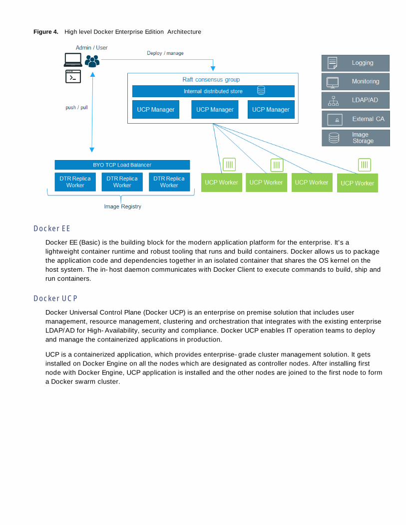
Figure 4. High level Docker Enterprise Edition Architecture
Docker EE
Docker EE (Basic) is the building block for the modern application platform for the enterprise. It's a
lightweight container runtime and robust tooling that runs and build containers. Docker allows us to package
the application code and dependencies together in an isolated container that shares the OS kernel on the
host system. The in-host daemon communicates with Docker Client to execute commands to build, ship and
run containers.
Docker UCP
Docker Universal Control Plane (Docker UCP) is an enterprise on premise solution that includes user
management, resource management, clustering and orchestration that integrates with the existing enterprise
LDAP/AD for High-Availability, security and compliance. Docker UCP enables IT operation teams to deploy
and manage the containerized applications in production.
UCP is a containerized application, which provides enterprise-grade cluster management solution. It gets
installed on Docker Engine on all the nodes which are designated as controller nodes. After installing first
node with Docker Engine, UCP application is installed and the other nodes are joined to the first node to form
a Docker swarm cluster.

Figure 5. Docker EE (Datacenter Cluster)
A Docker UCP cluster has two types of nodes:
UCP Controller Node
UCP Node
UCP Controller Node
Docker UCP controller node manages the cluster and provides persistent cluster configurations. Within
controller nodes there are two categories of nodes Master and Replicas. A first node which gets installed
with UCP is treated as a Master Controller node. And controller nodes joining the master controller node are
termed as Replica nodes. Controller nodes can take up application container workload as well. This is a
configurable option available at the admin and user level.
Figure 6. Docker UCP Controller
Table 1. Docker UCP Controller node containers and their description
Name Description
ucp-proxy A TLS proxy. It allows secure access to the local Docker Engine.
ucp-controller The UCP application. It uses the key-value store for persisting
configurations.
ucp-swarm-
manager
Provides the clustering capabilities. It uses the key-value store for
leader election, and keeping track of cluster members.
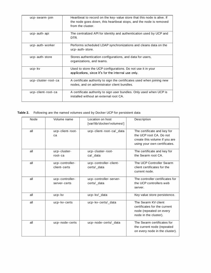
ucp-swarm-join Heartbeat to record on the key-value store that this node is alive. If
the node goes down, this heartbeat stops, and the node is removed
from the cluster.
ucp-auth-api The centralized API for identity and authentication used by UCP and
DTR.
ucp-auth-worker Performs scheduled LDAP synchronizations and cleans data on the
ucp-auth-store.
ucp-auth-store Stores authentication configurations, and data for users,
organizations, and teams.
ucp-kv Used to store the UCP configurations. Do not use it in your
ucp-cluster-root-ca A certificate authority to sign the certificates used when joining new
nodes, and on administrator client bundles.
ucp-client-root-ca A certificate authority to sign user bundles. Only used when UCP is
installed without an external root CA.
Table 2. Following are the named volumes used by Docker UCP for persistent data
Node Volume name Location on host
[var/lib/docker/volumes/]
Description
all ucp-client-root-
ca
ucp-client-root-ca/_data The certificate and key for
the UCP root CA. Do not
create this volume if you are
using your own certificates.
all ucp-cluster-
root-ca
ucp-cluster-root-
ca/_data
The certificate and key for
the Swarm root CA.
all ucp-controller-
client-certs
ucp-controller-client-
certs/_data
The UCP Controller Swarm
client certificates for the
current node.
all ucp-controller-
server-certs
ucp-controller-server-
certs/_data
The controller certificates for
the UCP controllers web
server.
all ucp-kv ucp-kv/_data Key value store persistence.
all ucp-kv-certs ucp-kv-certs/_data The Swarm KV client
certificates for the current
node (repeated on every
node in the cluster).
all ucp-node-certs ucp-node-certs/_data The Swarm certificates for
the current node (repeated
on every node in the cluster).
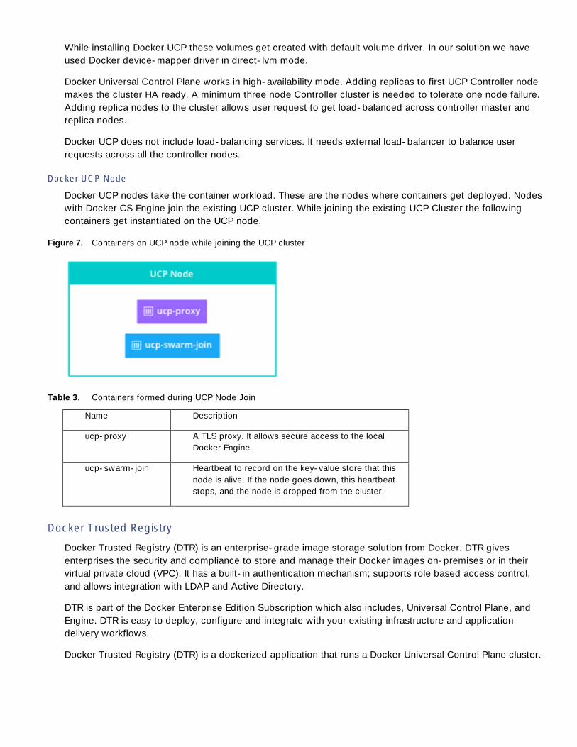
While installing Docker UCP these volumes get created with default volume driver. In our solution we have
used Docker device-mapper driver in direct-lvm mode.
Docker Universal Control Plane works in high-availability mode. Adding replicas to first UCP Controller node
makes the cluster HA ready. A minimum three node Controller cluster is needed to tolerate one node failure.
Adding replica nodes to the cluster allows user request to get load-balanced across controller master and
replica nodes.
Docker UCP does not include load-balancing services. It needs external load-balancer to balance user
requests across all the controller nodes.
Docker UCP Node
Docker UCP nodes take the container workload. These are the nodes where containers get deployed. Nodes
with Docker CS Engine join the existing UCP cluster. While joining the existing UCP Cluster the following
containers get instantiated on the UCP node.
Figure 7. Containers on UCP node while joining the UCP cluster
Table 3. Containers formed during UCP Node Join
Name Description
ucp-proxy A TLS proxy. It allows secure access to the local
Docker Engine.
ucp-swarm-join Heartbeat to record on the key-value store that this
node is alive. If the node goes down, this heartbeat
stops, and the node is dropped from the cluster.
Docker Trusted Registry
Docker Trusted Registry (DTR) is an enterprise-grade image storage solution from Docker. DTR gives
enterprises the security and compliance to store and manage their Docker images on-premises or in their
virtual private cloud (VPC). It has a built-in authentication mechanism; supports role based access control,
and allows integration with LDAP and Active Directory.
DTR is part of the Docker Enterprise Edition Subscription which also includes, Universal Control Plane, and
Engine. DTR is easy to deploy, configure and integrate with your existing infrastructure and application
delivery workflows.
Docker Trusted Registry (DTR) is a dockerized application that runs a Docker Universal Control Plane cluster.

Table 4. With DTR installation the following containers are started
Name Description
dtr-nginx-<replica_id> Receives http and https requests and proxies them to
other DTR components. By default it listens to ports 80
and 443 of the host.
dtr-api-<replica_id> Executes the DTR business logic. It serves the DTR web
application, and API.
dtr-registry-
<replica_id>
Implements the functionality for pulling and pushing
Docker images. It also handles how images are stored.
dtr-etcd-<replica_id> A key-value store for persisting DTR configuration
internal use only.
dtr-rethinkdb-
<replica_id>
dtr-jobrunner-
<replica_id>
Runs cleanup jobs in the background
dtr-notary-signer-
<replica_id>
Performs server-side timestamp and snapshot signing
for content trust metadata
dtr-notary-server-
<replica_id>
Receives, validates, and serves content trust metadata,
and is consulted when pushing or pulling to DTR with
content trust enabled
The communication between all DTR components is secured using TLS. Also, when installing DTR, two
certificate authority (CA) are created. These CAs are used to create the certificates used by etcd and
rethinkDB when communicating across nodes.
Table 5. Following networking gets created when DTR containers communicate with each other
Name Type Description
dtr-br bridge Allows containers on the same node to
communicate with each other in a secure
way.
dtr-ol overlay Allows containers running on different
nodes to communicate. This network is
used in high-availability installations, to
allow etcd and rethinkDB containers to
replicate their data.
Table 6. DTR uses following named volumes for persistent data
Volume name Description

dtr-ca-<replica_id> The volume where the private keys and certificates are
stored so that containers can use TLS to communicate.
dtr-etcd-<replica_id> The volume used by etcd to persist DTR configurations.
dtr-registry-<replica_id> The volume where images are stored, if DTR is configured to
store images on the local filesystem.
dtr-rethink-<replica_id> The volume used by RethinkDB to persist DTR data, like
users and repositories.
dtr-nfs-registry-<replica_id> Docker images data, if DTR is configured to store images on
NFS
dtr-notary-<replica_id> Certificate and keys for the Notary components
- -
availability.
For load balancing and high-availability, multiple replicas of DTR are installed and get joined to form a cluster, within
Docker EE UCP cluster. When joining new replicas to the cluster, we create new DTR instances that are running the
same set of services. Any change to the state of an instance is replicated across all the other instances.
Figure 8. DTR Cluster behind load balancer
Having a DTR cluster with multiple replicas, allows us to:
Load-balance user requests across the DTR replicas
Keep the DTR cluster up and running when a replica fails
DTR does not provide a load balancing service. An on-premises or cloud-based load balancer is required to
balance requests across multiple DTR replicas. Load balancer is required to be configured:
On TCP ports 80 and 443
On a TCP load balancer which does not terminates the HTTPS connections

Solution Design
This section provides an overview of the hardware and software components used in this solution, as well as
the design factors to be considered in order to make the system work as a single, highly available solution
Architectural Overview
This solution consists of Cisco UCS B-Series servers, Cisco UCS Fabric Interconnects, Cisco Nexus TOR
switches, and NetApp AFF8040 storage. The Docker Enterprise Edition is certified on Red Hat Enterprise
Linux Operating System. Cisco UCS servers provide converged and highly available hardware platform
centrally managed by Cisco UCS Manager software residing on Cisco Fabric Interconnects. As an important
component of the Docker Enterprise Edition, Docker Universal Control Plane provides the redundancy and
high-availability of the Docker Engine and management control plane. This solution holistically offers
Container management for diverse application environment to be deployed in DevOps and Production use
cases.
Compute nodes for Docker are configured to run on Cisco B-Series servers. In some cases, compute node
resources could be shared between the control plane software stack and the container engine. Docker
Universal Control Plane services are spread over three B-Series servers for providing management control
plane redundancy and high-availability. DTR services and its replicas are configured to run on three
dedicated B-Series servers as part of Docker EE.
The following figure illustrates the physical backend connectivity of the hardware components.

Figure 9. Cabling Diagram
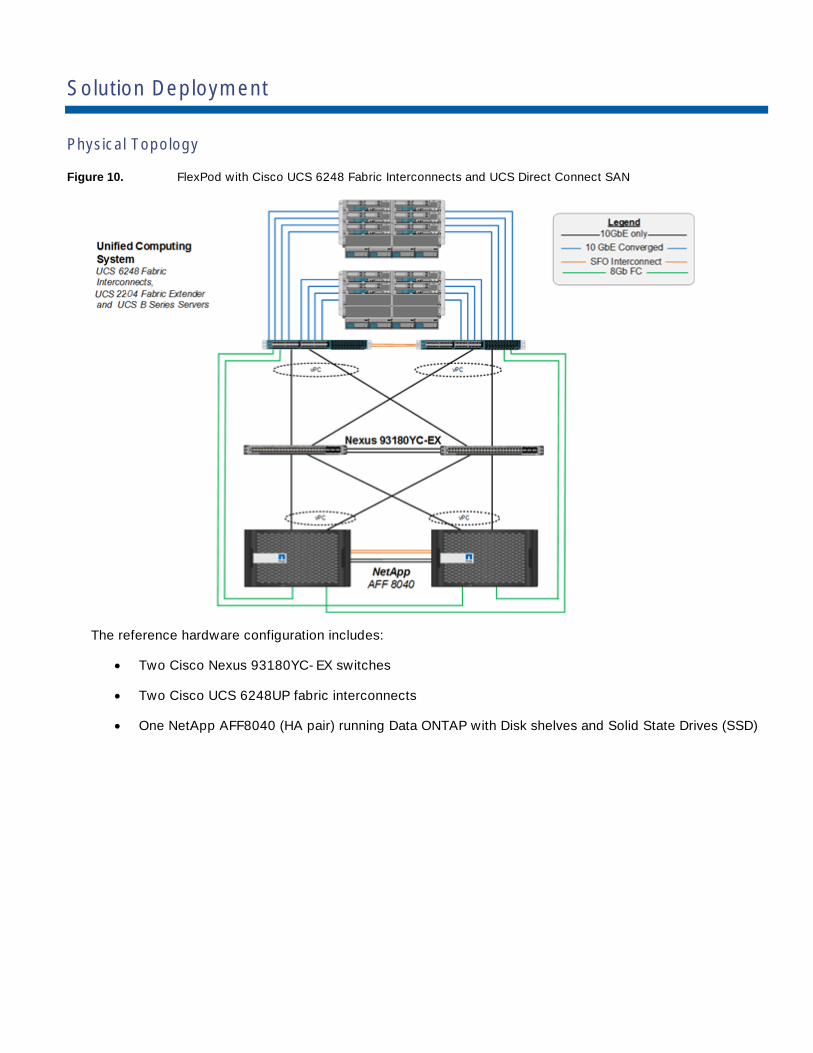
Solution Deployment
Physical Topology
Figure 10. FlexPod with Cisco UCS 6248 Fabric Interconnects and UCS Direct Connect SAN
The reference hardware configuration includes:
Two Cisco Nexus 93180YC-EX switches
Two Cisco UCS 6248UP fabric interconnects
One NetApp AFF8040 (HA pair) running Data ONTAP with Disk shelves and Solid State Drives (SSD)

Deployment Hardware and Software
Deployment Hardware
Table 7. Solution Component Details
Component Model Quantity Comments
UCP Controller,
UCP and DTR
nodes
Cisco UCS B200
M4 Servers
10 CPU 2 x E5-2660 V4
Memory 16 x 16GB 2133 DIMM total of 256G
Network Card 1x1340 VIC + Port Expander
Chassis Cisco UCS 5108
Chassis
2
IO Modules Cisco UCS
2204XP Fabric
Extenders
4
Fabric
Interconnects
Cisco UCS
6248UP Fabric
Interconnects
2
ToR Switches Cisco Nexus
93180YC-EX
Switches
2
Software Revisions
Table 8 lists the software revisions for this solution.
Table 8. Software Revisions
Layer Device Image Comments
Compute Cisco UCS Fabric
Interconnects 6200 and
6300 Series, UCS B-200
M4
3.1(2f) Includes the Cisco UCS
IOM-2208XP, and 2204XP
Cisco UCS Manager, and
Cisco UCS VIC 1340
Cisco eNIC 2.3.0.30
Cisco fNIC 1.6.0.30
Network Cisco Nexus 9000 NX-OS 7.0(3)I4(5)
Storage NetApp AFF 8040 Data ONTAP 9.0
Software Cisco UCS Manager 3.1(2f)

Red Hat Enterprise Linux 7.3
Docker Universal Control
Plane (UCP)
2.1.2
Docker Trusted Registry
(DTR)
2.2.3
Docker EE (Basic) 17.03.1-ee-3
NetApp Docker Volume
Plugin
1.4
Configuration Guidelines
This document provides details for configuring a fully redundant, highly available configuration for a FlexPod
unit with clustered Data ONTAP storage. Therefore, reference is made to which component is being
configured with each step, either 01 or 02 or A and B. For example, node01 and node02 are used to identify
the two NetApp storage controllers that are provisioned with this document, and Cisco Nexus A or Cisco
Nexus B identifies the pair of Cisco Nexus switches that are configured. The Cisco UCS fabric interconnects
are similarly configured. Additionally, this document details the steps for provisioning multiple Cisco UCS
hosts, and these examples are identified as: Docker-Host-01, Docker-Host-02 to represent infrastructure
and production hosts deployed to each of the fabric interconnects in this document. Finally, to indicate that
you should include information pertinent to your environment in a given step, <text> appears as part of the
command structure. See the following example for the network port vlan create command:
Usage:
network port vlan create ?
[-node] <nodename> Node
{ [-vlan-name] {<netport>|<ifgrp>} VLAN Name
| -port {<netport>|<ifgrp>} Associated Network Port
[-vlan-id] <integer> } Network Switch VLAN Identifier
Example:
network port vlan -node <node01> -vlan-name i0a-<vlan id>
This document is intended to enable you to fully configure the customer environment. In this process, various
steps require you to insert customer-specific naming conventions, IP addresses, and VLAN schemes, as well
as to record appropriate MAC addresses. Table 3 lists the virtual machines (VMs) necessary for deployment
as outlined in this guide. Table 9 describes the VLANs necessary for deployment as outlined in this guide.
Table 9. Necessary VLANs
VLAN Name VLAN Purpose ID Used in Validating This
Document
Out of Band Mgmt VLAN for out-of-band management interfaces 13
VLAN Name VLAN Purpose ID Used in Validating This
Document
Container Mgmt VLAN for in-band Container management interfaces 901
Native VLAN to which untagged frames are assigned 2
Container Mgmt
NFS VLAN for Container Management NFS traffic 902
Container Tenant A
NFS
VLAN for First Container Tenant NFS traffic 903
Table 9 lists the VLANs necessary for deployment as outlined in this document.
Physical Infrastructure
FlexPod Cabling
The information in this section is provided as a reference for cabling the physical equipment in a FlexPod
environment. To simplify cabling requirements, the tables include both local and remote device and port
locations.
The tables in this section contain the details for the prescribed and supported configuration of the NetApp
AFF8040 running Data ONTAP 9.0
For any modifications of this prescribed architecture, consult the NetApp Interoperability Matrix Tool (IMT).
This document assumes that out-of-band management ports are plugged into an existing management
infrastructure at the deployment site. These interfaces will be used in various configuration steps
Be sure to use the cabling directions in this section as a guide.
The NetApp storage controller and disk shelves should be connected according to best practices for the
specific storage controller and disk shelves. For disk shelf cabling, refer to the Universal SAS and ACP
Cabling Guide: https://library.netapp.com/ecm/ecm_get_file/ECMM1280392.
Table 10 through Table 15 provide the details of all the connections in use in the validation lab. Please use
these tables as a reference.
In the lab used for this validation, both UCS 6248UP and UCS 6332-16UP Fabric Interconnects were used
as noted in these tables.
Table 10. Cisco Nexus 9372-A Cabling Information
Local Device Local Port Connection Remote Device Remote
Port
Cisco Nexus 93180YC-EX A
Eth1/1 10GbE NetApp Controller 1 e0b
Eth1/2 10GbE NetApp Controller 2 e0b

Local Device Local Port Connection Remote Device Remote
Port
Eth1/9 10GbE Cisco UCS 6248UP FI A Eth1/27
Eth1/10 10GbE Cisco UCS 6248UP FI B Eth1/27
Eth1/45 10GbE Cisco Nexus 93180 B Eth1/45
Eth1/46 10GbE Cisco Nexus 93180 B Eth1/46
MGMT0 GbE GbE management switch Any
The vPC peer link shown here on 40 GbE ports 1/49 and 1/50 could also be placed on 10 GbE ports. It is
recommended to make the total bandwidth of the vPC peer link at least 40 Gb/s if using 40 GbE ports in
this architecture.
Table 11. Cisco Nexus 9372-B Cabling Information
Local Device Local Port Connection Remote Device Remote Port
Cisco Nexus 93180YC-EX
B
Eth1/1 10GbE NetApp Controller 1 e0d
Eth1/2 10GbE NetApp Controller 2 e0d
Eth1/9 10GbE Cisco UCS 6248UP FI A Eth1/28
Eth1/10 10GbE Cisco UCS 6248UP FI B Eth1/28
Eth1/44 10GbE Cisco Nexus 93180 A Eth1/45
Eth1/46 10GbE Cisco Nexus 93180 A Eth1/46
MGMT0 GbE GbE management switch Any
Table 12. NetApp Controller-1 Cabling Information
Local Device Local Port Connection Remote Device Remote
Port
NetApp controller 1 e0M GbE GbE management switch Any
Local Device Local Port Connection Remote Device Remote
Port
e0i GbE GbE management switch Any
e0P GbE SAS shelves ACP port
e0a 10GbE NetApp Controller 2 e0a
e0b 10GbE Cisco Nexus 93180 A Eth1/1
e0c 10GbE NetApp Controller 2 e0c
e0d 10GbE Cisco Nexus 93180 B Eth1/1
0g 8Gb FC For Direct Connect to UCS FI FC1/29
0h 8Gb FC For Direct Connect to UCS FI FC1/30
When the term e0M is used, the physical Ethernet port to which the table is referring is the port indicated by
a wrench icon on the rear of the chassis.
Table 13. NetApp Controller-2 Cabling Information
Local Device Local Port Connection Remote Device Remote
Port
NetApp controller 2 e0M GbE GbE management switch Any
e0i GbE GbE management switch Any
e0P GbE SAS shelves ACP port
e0a 10GbE NetApp Controller 1 e0a
e0b 10GbE Cisco Nexus 93180 A Eth1/2
e0c 10GbE NetApp Controller 1 e0c
e0d 10GbE Cisco Nexus 93180 B Eth1/2
0g 8Gb FC For Direct Connect to UCS FI FC1/29
0h 8Gb FC For Direct Connect to UCS FI FC1/30

Table 14. Cisco UCS 6248UP Fabric Interconnect A Cabling Information
Local Device Local Port Connection Remote Device Remote
Port
Cisco UCS fabric interconnect A
FC 1/29 8Gb FC NetApp Controller 1 0g
FC 1/30 8Gb FC NetApp Controller 2 0g
Eth1/1 10GbE Cisco UCS Chassis 1 2204 FEX A IOM 1/1
Eth1/2 10GbE Cisco UCS Chassis 1 2204 FEX A IOM 1/2
Eth1/3 10GbE Cisco UCS Chassis 1 2204 FEX A IOM 1/3
Eth1/4 10GbE Cisco UCS Chassis 1 2204 FEX A IOM 1/4
Eth1/5 10GbE Cisco UCS Chassis 2 2208 FEX A IOM 1/1
Eth1/6 10GbE Cisco UCS Chassis 2 2208 FEX A IOM 1/2
Eth1/7 10GbE Cisco UCS Chassis 2 2208FEX A IOM 1/3
Eth1/8 10GbE Cisco UCS Chassis 2 2208 FEX A IOM 1/4
Eth1/27 10GbE Cisco Nexus 93180 A Eth1/9
Eth1/28 10GbE Cisco Nexus 93180 B Eth1/9
MGMT0 GbE GbE management switch Any
L1 GbE Cisco UCS 6248UP FI B L1
L2 GbE Cisco UCS 6248UP FI B L2
Table 15. Cisco UCS 6248UP Fabric Interconnect B Cabling Information
Local Device Local Port Connection Remote Device Remote
Port
Cisco UCS fabric interconnect B
FC 1/29 8Gb FC NetApp Controller 1 0h
FC 1/30 8Gb FC NetApp Controller 2 0h
Eth1/1 10GbE Cisco UCS Chassis 1 2204 FEX B IOM 1/1
Eth1/2 10GbE Cisco UCS Chassis 1 2204 FEX B IOM 1/2
Eth1/3 10GbE Cisco UCS Chassis 1 2204 FEX B IOM 1/3

Local Device Local Port Connection Remote Device Remote
Port
Eth1/4 10GbE Cisco UCS Chassis 1 2204 FEX B IOM 1/4
Eth1/5 10GbE Cisco UCS Chassis 2 2208 FEX B IOM 1/1
Eth1/6 10GbE Cisco UCS Chassis 2 2208 FEX B IOM 1/2
Eth1/7 10GbE Cisco UCS Chassis 2 2208FEX B IOM 1/3
Eth1/8 10GbE Cisco UCS Chassis 2 2208 FEX B IOM 1/4
Eth1/27 10GbE Cisco Nexus 93180 A Eth1/10
Eth1/28 10GbE Cisco Nexus 93180 B Eth1/10
MGMT0 GbE GbE management switch Any
L1 GbE Cisco UCS 6248UP FI B L1
L2 GbE Cisco UCS 6248UP FI B L2
FlexPod Cisco Nexus Base
The following procedures describe how to configure the Cisco Nexus switches for use in a base FlexPod
environment. This procedure assumes the use of Nexus 9000 7.0(3)I4(5).
The following procedure includes setup of NTP distribution on the Container Management VLAN. The in-
terface-vlan feature and ntp commands are used to set this up. This procedure also assumes the default
VRF will be used to route the Container Management VLAN.
Set Up Initial Configuration
Cisco Nexus 93180YC-EX A
To set up the initial configuration for the Cisco Nexus A switch on <nexus-A-hostname>, complete the
following steps:
1. Configure the switch.
On initial boot and connection to the serial or console port of the switch, the NX-OS setup should
automatically start and attempt to enter Power on Auto Provisioning.
Abort Power on Auto Provisioning and continue with normal setup? (yes/no) [n]: yes
Do you want to enforce secure password standard (yes/no): yes
Enter the password for "admin": <password>
Confirm the password for "admin": <password>

Would you like to enter the basic configuration dialog (yes/no): yes
Create another login account (yes/no) [n]: Enter
Configure read-only SNMP community string (yes/no) [n]: Enter
Configure read-write SNMP community string (yes/no) [n]: Enter
Enter the switch name: <nexus-A-hostname>
Continue with Out-of-band (mgmt0) management configuration? (yes/no) [y]: Enter
Mgmt0 IPv4 address: <nexus-A-mgmt0-ip>
Mgmt0 IPv4 netmask: <nexus-A-mgmt0-netmask>
Configure the default gateway? (yes/no) [y]: Enter
IPv4 address of the default gateway: <nexus-A-mgmt0-gw>
Configure advanced IP options? (yes/no) [n]: Enter
Enable the telnet service? (yes/no) [n]: Enter
Enable the ssh service? (yes/no) [y]: Enter
Type of ssh key you would like to generate (dsa/rsa) [rsa]: Enter
Number of rsa key bits <1024-2048> [1024]: Enter
Configure the ntp server? (yes/no) [n]: y
NTP server IPv4 address: <global-ntp-server-ip>
Configure default interface layer (L3/L2) [L2]: Enter
Configure default switchport interface state (shut/noshut) [noshut]: shut
Configure CoPP system profile (strict/moderate/lenient/dense/skip) [strict]: Enter
Would you like to edit the configuration? (yes/no) [n]: Enter
2. Review the configuration summary before enabling the configuration.
Use this configuration and save it? (yes/no) [y]: Enter
Cisco Nexus 93180YC-EX B
To set up the initial configuration for the Cisco Nexus B switch on <nexus-B-hostname>, complete the
following steps:
1. Configure the switch.
On initial boot and connection to the serial or console port of the switch, the NX-OS setup should
automatically start and attempt to enter Power on Auto Provisioning.
Abort Power on Auto Provisioning and continue with normal setup? (yes/no) [n]: yes
Do you want to enforce secure password standard (yes/no): yes
Enter the password for "admin": <password>

Confirm the password for "admin": <password>
Would you like to enter the basic configuration dialog (yes/no): yes
Create another login account (yes/no) [n]: Enter
Configure read-only SNMP community string (yes/no) [n]: Enter
Configure read-write SNMP community string (yes/no) [n]: Enter
Enter the switch name: <nexus-B-hostname>
Continue with Out-of-band (mgmt0) management configuration? (yes/no) [y]: Enter
Mgmt0 IPv4 address: <nexus-B-mgmt0-ip>
Mgmt0 IPv4 netmask: <nexus-B-mgmt0-netmask>
Configure the default gateway? (yes/no) [y]: Enter
IPv4 address of the default gateway: <nexus-B-mgmt0-gw>
Configure advanced IP options? (yes/no) [n]: Enter
Enable the telnet service? (yes/no) [n]: Enter
Enable the ssh service? (yes/no) [y]: Enter
Type of ssh key you would like to generate (dsa/rsa) [rsa]: Enter
Number of rsa key bits <1024-2048> [1024]: Enter
Configure the ntp server? (yes/no) [n]: y
NTP server IPv4 address: <global-ntp-server-ip>
Configure default interface layer (L3/L2) [L2]: Enter
Configure default switchport interface state (shut/noshut) [noshut]: shut
Configure CoPP system profile (strict/moderate/lenient/dense/skip) [strict]: Enter
Would you like to edit the configuration? (yes/no) [n]: Enter
2. Review the configuration summary before enabling the configuration.
Use this configuration and save it? (yes/no) [y]: Enter
FlexPod Cisco Nexus Switch Configuration
Enable Licenses
Cisco Nexus 93180YC-EX A and Cisco Nexus 93180YC-EX B
To license the Cisco Nexus switches, complete the following steps:
1. Log in as admin.
2. Run the following commands:

config t
feature interface-vlan
feature lacp
feature vpc
feature lldp
feature nxapi
Set Global Configurations
Cisco Nexus 93180YC-EX A and Cisco Nexus 93180YC-EX B
To set global configurations, complete the following step on both switches:
Run the following commands to set global configurations:
spanning-tree port type network default
spanning-tree port type edge bpduguard default
spanning-tree port type edge bpdufilter default
port-channel load-balance src-dst l4port
ntp server <global-ntp-server-ip> use-vrf management
ntp master 3
ip route 0.0.0.0/0 <docker-vlan-gateway>
copy run start
Create VLANs
Cisco Nexus 93180YC-EX A and Cisco Nexus 93180YC-EX B
To create the necessary virtual local area networks (VLANs), complete the following step on both switches:
From the global configuration mode, run the following commands:
vlan <cntr-mgmt-vlan-id>
name Container-VLAN
exit
vlan <native-vlan-id>
name Native-VLAN
exit
vlan <cntr-mgmt-nfs-vlan-id>
name Cntr-MGMT-NFS-VLAN
exit
vlan <cntr-tnt-a-nfs-vlan-id>

name Cntr-TNT-A-NFS-VLAN
exit
Add NTP Distribution Interface
Cisco Nexus 93180YC-EX A
From the global configuration mode, run the following commands to add the NTP distribution IP in the
Container Management VLAN:
ntp source <switch-a-ntp-ip>
interface Vlan<cntr-mgmt-vlan-id>
ip address <switch-a-ntp-ip>/<cntr-mgmt-vlan-netmask-length>
no shutdown
exit
Cisco Nexus 93180YC-EX B
From the global configuration mode, run the following commands to add the NTP distribution IP in the
Container Management VLAN:
ntp source <switch-b-ntp-ip>
interface Vlan<cntr-mgmt-vlan-id>
ip address <switch-b-ntp-ip>/<cntr-mgmt-vlan-netmask-length>
no shutdown
exit
Add Individual Port Descriptions for Troubleshooting
Cisco Nexus 93180YC-EX A
To add individual port descriptions for troubleshooting activity and verification for switch A, complete the
following step:
In this step and in further sections, configure the <ucs-6248-clustername> interface as appropriate to your
deployment.
From the global configuration mode, run the following commands:
interface Eth1/1
description <st-node01>:e0b
exit
interface Eth1/2
description <st-node02>:e0b
exit

interface Eth1/9
description <ucs-6248-clustername>-a:1/27
exit
interface Eth1/10
description <ucs-6248-clustername>-b:1/27
exit
interface Eth1/45
description <nexus-B-hostname>:1/45
exit
interface Eth1/46
description <nexus-B-hostname>:1/46
exit
Cisco Nexus 93180YC-EX B
To add individual port descriptions for troubleshooting activity and verification for switch B, complete the
following step:
From the global configuration mode, run the following commands:
interface Eth1/1
description <st-node01>:e0d
exit
interface Eth1/2
description <st-node02>:e0d
exit
interface Eth1/9
description <ucs-6248-clustername>-a:1/28
exit
interface Eth1/10
description <ucs-6248-clustername>-b:1/28
exit
interface Eth1/45
description <nexus-A-hostname>:1/45
exit
interface Eth1/46
description <nexus-A-hostname>:1/46
exit

Create Port Channels
Cisco Nexus 93180YC-EX A and Cisco Nexus 93180YC-EX B
To create the necessary port channels between devices, complete the following step on both switches:
From the global configuration mode, run the following commands:
interface Po10
description vPC peer-link
exit
interface Eth1/45-46
channel-group 10 mode active
no shutdown
exit
interface Po11
description <st-node01>
exit
interface Eth1/1
channel-group 11 mode active
no shutdown
exit
interface Po12
description <st-node02>
exit
interface Eth1/2
channel-group 12 mode active
no shutdown
exit
interface Po19
description <ucs-6248-clustername>-a
exit
interface Eth1/9
channel-group 19 mode active
no shutdown
exit
interface Po110

description <ucs-6248-clustername>-b
exit
interface Eth1/10
channel-group 110 mode active
no shutdown
exit
copy run start
Configure Port Channel Parameters
Cisco Nexus 93180YC-EX A and Cisco Nexus 93180YC-EX B
To configure port channel parameters, complete the following step on both switches:
From the global configuration mode, run the following commands:
interface Po10
switchport mode trunk
switchport trunk native vlan 2
switchport trunk allowed vlan <cntr-mgmt-vlan-id>,<cntr-mgmt-nfs-vlan-id>,<cntr-tnt-a-nfs-vlan-id>
spanning-tree port type network
exit
interface Po11
switchport mode trunk
switchport trunk native vlan 2
switchport trunk allowed vlan <cntr-mgmt-vlan-id>,<cntr-mgmt-nfs-vlan-id>,<cntr-tnt-a-nfs-vlan-id>
spanning-tree port type edge trunk
mtu 9216
exit
interface Po12
switchport mode trunk
switchport trunk native vlan 2
switchport trunk allowed vlan <cntr-mgmt-vlan-id>,<cntr-mgmt-nfs-vlan-id>,<cntr-tnt-a-nfs-vlan-id>
spanning-tree port type edge trunk
mtu 9216
exit
interface Po19
switchport mode trunk

switchport trunk native vlan 2
switchport trunk allowed vlan <cntr-mgmt-vlan-id>,<cntr-mgmt-nfs-vlan-id>,<cntr-tnt-a-nfs-vlan-id>
spanning-tree port type edge trunk
mtu 9216
exit
interface Po110
switchport mode trunk
switchport trunk native vlan 2
switchport trunk allowed vlan <cntr-mgmt-vlan-id>,<cntr-mgmt-nfs-vlan-id>,<cntr-tnt-a-nfs-vlan-id>
spanning-tree port type edge trunk
mtu 9216
exit
copy run start
Configure Virtual Port Channels
Cisco Nexus 93180YC-EX A
To configure virtual port channels (vPCs) for switch A, complete the following step:
From the global configuration mode, run the following commands:
vpc domain <nexus-vpc-domain-id>
role priority 10
peer-keepalive destination <nexus-B-mgmt0-ip> source <nexus-A-mgmt0-ip>
peer-switch
peer-gateway
auto-recovery
delay restore 150
exit
interface Po10
vpc peer-link
exit
interface Po11
vpc 11
exit
interface Po12
vpc 12

exit
interface Po19
vpc 19
exit
interface Po110
vpc 110
exit
copy run start
Cisco Nexus 93180YC-EX B
To configure vPCs for switch B, complete the following step:
From the global configuration mode, run the following commands.
vpc domain <nexus-vpc-domain-id>
role priority 20
peer-keepalive destination <nexus-A-mgmt0-ip> source <nexus-B-mgmt0-ip>
peer-switch
peer-gateway
auto-recovery
delay restore 150
exit
interface Po10
vpc peer-link
exit
interface Po11
vpc 11
exit
interface Po12
vpc 12
exit
interface Po19
vpc 19
exit
interface Po110
vpc 110
exit
copy run start
Uplink into Existing Network Infrastructure
Depending on the available network infrastructure, several methods and features can be used to uplink the
FlexPod environment. If an existing Cisco Nexus environment is present, NetApp recommends using vPCs to
uplink the Cisco Nexus 93190YC-EX switches included in the FlexPod environment into the infrastructure.
The previously described procedures can be used to create an uplink vPC to the existing environment. Make
sure to run copy run start to save the configuration on each switch after the configuration is completed.
NetApp Storage Configuration
See the following sections in the Site Requirements Guide for planning the physical location of the storage
systems:
Site Preparation
System Connectivity Requirements
Circuit Breaker, Power Outlet Balancing, System Cabinet Power Cord Plugs, and Console Pinout
Requirements
NetApp 80xx Series Systems
NetApp Hardware Universe
The NetApp Hardware Universe (HWU) application provides supported hardware and software components
for any specific ONTAP version. It provides configuration information for all the NetApp storage appliances
currently supported by ONTAP software. It also provides a table of component compatibilities.
Confirm that the hardware and software components that you would like to use are supported with the
version of ONTAP that you plan to install by using the HWU application at the NetApp Support site. Access
the HWU application to view the system configuration guides. Click the Controllers tab to view the
compatibility between different version of ONTAP software and the NetApp storage appliances with your
desired specifications. Alternatively, to compare components by storage appliance, click Compare Storage
Systems.
Controllers
Follow the physical installation procedures for the controllers found in the AFF8000 Series product
documentation at the NetApp Support site.
Disk Shelves
NetApp storage systems support a wide variety of disk shelves and disk drives. The complete list of disk
shelves that are supported by the AFF 80xx is available at the NetApp Support site.
To use SAS disk shelves with NetApp storage controllers, refer to the SAS Disk Shelves Universal SAS and
ACP Cabling Guide for proper cabling guidelines.

ONTAP 9.0
Complete Configuration Worksheet
Before running the setup script, complete the cluster setup worksheet from the ONTAP 9 Software Setup
Guide. You must have access to the NetApp Support site to open the cluster setup worksheet.
Configure ONTAP Nodes
Before running the setup script, review the configuration worksheets in the ONTAP 9 Software Setup Guide
to learn about configuring ONTAP. Table 16 lists the information needed to configure two ONTAP nodes.
Customize the cluster detail values with the information applicable to your deployment.
Table 16. ONTAP software installation prerequisites
Cluster Detail Cluster Detail Value
Cluster Node01 IP address <node01-mgmt-ip>
Cluster Node01 netmask <node01-mgmt-mask>
Cluster Node01 gateway <node01-mgmt-gateway>
Cluster Node02 IP address <node02-mgmt-ip>
Cluster Node02 netmask <node02-mgmt-mask>
Cluster Node02 gateway <node02-mgmt-gateway>
Data ONTAP 9.0 URL <url-boot-software>
Configure Node 01
To configure node 01, complete the following steps:
1. Connect to the storage system console port. You should see a Loader-A prompt. However, if the
storage system is in a reboot loop, press Ctrl-C to exit the autoboot loop when you see this
message:
Starting AUTOBOOT press Ctrl-C to abort…
2. Allow the system to boot up.
autoboot
3. Press Ctrl-C when prompted.
If ONTAP 9 is not the version of software being booted, continue with the following steps to install
new software. If ONTAP 9 is the version being booted, select option 8 and y to reboot the node.
Then continue with step 14.

4. To install new software, select option 7.
7
5. Enter y to perform an upgrade.
y
6. Select e0M for the network port you want to use for the download.
e0M
7. Enter y to reboot now.
y
8. Enter the IP address, netmask, and default gateway for e0M in their respective places.
<node01-mgmt-ip> <node01-mgmt-mask> <node01-mgmt-gateway>
9. Enter the URL where the software can be found.
This web server must be pingable.
<url-boot-software>
10. Press Enter for the user name, indicating no user name.
11. Enter y to set the newly installed software as the default to be used for subsequent reboots.
y
12. Enter y to reboot the node.
y
When installing new software, the system might perform firmware upgrades to the BIOS and adapter cards, caus-
ing reboots and possible stops at the Loader-A prompt. If these actions occur, the system might deviate
from this procedure.
13. Press Ctrl-C when you see this message:
Press Ctrl-C for Boot Menu
14. Select option 4 for Clean Configuration and Initialize All Disks.
4
15. Enter y to zero disks, reset config, and install a new file system.
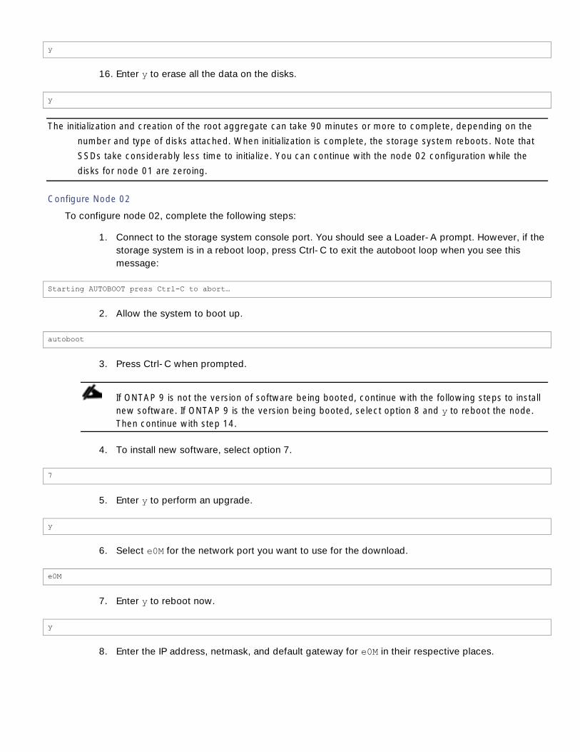
y
16. Enter y to erase all the data on the disks.
y
The initialization and creation of the root aggregate can take 90 minutes or more to complete, depending on the
number and type of disks attached. When initialization is complete, the storage system reboots. Note that
SSDs take considerably less time to initialize. You can continue with the node 02 configuration while the
disks for node 01 are zeroing.
Configure Node 02
To configure node 02, complete the following steps:
1. Connect to the storage system console port. You should see a Loader-A prompt. However, if the
storage system is in a reboot loop, press Ctrl-C to exit the autoboot loop when you see this
message:
Starting AUTOBOOT press Ctrl-C to abort…
2. Allow the system to boot up.
autoboot
3. Press Ctrl-C when prompted.
If ONTAP 9 is not the version of software being booted, continue with the following steps to install
new software. If ONTAP 9 is the version being booted, select option 8 and y to reboot the node.
Then continue with step 14.
4. To install new software, select option 7.
7
5. Enter y to perform an upgrade.
y
6. Select e0M for the network port you want to use for the download.
e0M
7. Enter y to reboot now.
y
8. Enter the IP address, netmask, and default gateway for e0M in their respective places.
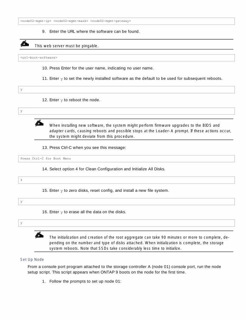
<node02-mgmt-ip> <node02-mgmt-mask> <node02-mgmt-gateway>
9. Enter the URL where the software can be found.
This web server must be pingable.
<url-boot-software>
10. Press Enter for the user name, indicating no user name.
11. Enter y to set the newly installed software as the default to be used for subsequent reboots.
y
12. Enter y to reboot the node.
y
When installing new software, the system might perform firmware upgrades to the BIOS and
adapter cards, causing reboots and possible stops at the Loader-A prompt. If these actions occur,
the system might deviate from this procedure.
13. Press Ctrl-C when you see this message:
Press Ctrl-C for Boot Menu
14. Select option 4 for Clean Configuration and Initialize All Disks.
4
15. Enter y to zero disks, reset config, and install a new file system.
y
16. Enter y to erase all the data on the disks.
y
The initialization and creation of the root aggregate can take 90 minutes or more to complete, de-
pending on the number and type of disks attached. When initialization is complete, the storage
system reboots. Note that SSDs take considerably less time to initialize.
Set Up Node
From a console port program attached to the storage controller A (node 01) console port, run the node
setup script. This script appears when ONTAP 9 boots on the node for the first time.
1. Follow the prompts to set up node 01:

Welcome to node setup.
You can enter the following commands at any time:
"help" or "?" - if you want to have a question clarified,
"back" - if you want to change previously answered questions, and
"exit" or "quit" - if you want to quit the setup wizard.
Any changes you made before quitting will be saved.
To accept a default or omit a question, do not enter a value.
This system will send event messages and weekly reports to NetApp Technical Support.
To disable this feature, enter "autosupport modify -support disable" within 24 hours.
Enabling AutoSupport can significantly speed problem determination and resolution should a problem occur on
your system.
For further information on AutoSupport, see:
http://support.netapp.com/autosupport/
Type yes to confirm and continue {yes}: yes
Enter the node management interface port [e0M]: Enter
Enter the node management interface IP address: <node01-mgmt-ip>
Enter the node management interface netmask: <node01-mgmt-mask>
Enter the node management interface default gateway: <node01-mgmt-gateway>
A node management interface on port e0M with IP address <node01-mgmt-ip> has been created
This node has its management address assigned and is ready for cluster setup.
To complete cluster setup after all nodes are ready, download and run the System Setup utility from the
NetApp Support Site and use it to discover the configured nodes.
For System Setup, this node's management address is: <node01-mgmt-ip>.
Alternatively, you can use the "cluster setup" command to configure the cluster.
2. Press Enter and log in to the node with the admin user ID and no password.

3. At the node command prompt, enter the following commands to set HA mode for storage failo-
ver.
If the node responds that the HA mode was already set, then proceed with step 4.
::> storage failover modify -mode ha
Mode set to HA. Reboot node to activate HA.
::> system node reboot
Warning: Are you sure you want to reboot node "localhost"? {y|n}: y
4. After reboot, set up the node with the preassigned values.
Welcome to node setup.
You can enter the following commands at any time:
"help" or "?" - if you want to have a question clarified,
"back" - if you want to change previously answered questions, and
"exit" or "quit" - if you want to quit the setup wizard.
Any changes you made before quitting will be saved.
To accept a default or omit a question, do not enter a value.
Enter the node management interface port [e0M]: Enter
Enter the node management interface IP address [<node01-mgmt-ip>]: Enter
Enter the node management interface netmask [<node01-mgmt-mask>]: Enter
Enter the node management interface default gateway [<node01-mgmt-gateway>]: Enter
This node has its management address assigned and is ready for cluster setup.
To complete cluster setup after all nodes are ready, download and run the System Setup utility from the
NetApp Support Site and use it to discover the configured nodes.
For System Setup, this node's management address is: <node01-mgmt-ip>.
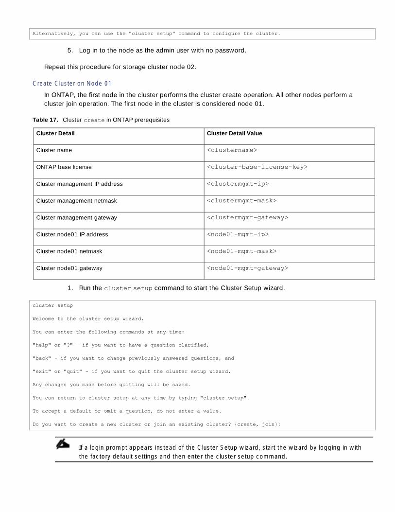
Alternatively, you can use the "cluster setup" command to configure the cluster.
5. Log in to the node as the admin user with no password.
Repeat this procedure for storage cluster node 02.
Create Cluster on Node 01
In ONTAP, the first node in the cluster performs the cluster create operation. All other nodes perform a
cluster join operation. The first node in the cluster is considered node 01.
Table 17. Cluster create in ONTAP prerequisites
Cluster Detail Cluster Detail Value
Cluster name <clustername>
ONTAP base license <cluster-base-license-key>
Cluster management IP address <clustermgmt-ip>
Cluster management netmask <clustermgmt-mask>
Cluster management gateway <clustermgmt-gateway>
Cluster node01 IP address <node01-mgmt-ip>
Cluster node01 netmask <node01-mgmt-mask>
Cluster node01 gateway <node01-mgmt-gateway>
1. Run the cluster setup command to start the Cluster Setup wizard.
cluster setup
Welcome to the cluster setup wizard.
You can enter the following commands at any time:
"help" or "?" - if you want to have a question clarified,
"back" - if you want to change previously answered questions, and
"exit" or "quit" - if you want to quit the cluster setup wizard.
Any changes you made before quitting will be saved.
You can return to cluster setup at any time by typing "cluster setup".
To accept a default or omit a question, do not enter a value.
Do you want to create a new cluster or join an existing cluster? {create, join}:
If a login prompt appears instead of the Cluster Setup wizard, start the wizard by logging in with
the factory default settings and then enter the cluster setup command.

2. Run the following command to create a new cluster:
create
3. Enter no for the single-node cluster option.
Do you intend for this node to be used as a single node cluster? {yes, no} [no]: no
4. Enter no for a cluster network using network switches.
Will the cluster network be configured to use network switches? [yes]:no
5. The system defaults are displayed. Enter yes to use the system defaults. Use the following
prompts to configure the cluster ports.
Existing cluster interface configuration found:
Port MTU IP Netmask
e0a 9000 169.254.118.102 255.255.0.0
e0c 9000 169.254.191.92 255.255.0.0
Do you want to use this configuration? {yes, no} [yes]: no
System Defaults:
Private cluster network ports [e0a,e0c].
Cluster port MTU values will be set to 9000.
Cluster interface IP addresses will be automatically generated.
Do you want to use these defaults? {yes, no} [yes]: yes
If four ports are being used for the switchless cluster interconnect, enter e0a, e0b, e0c, and e0d
for the private cluster network ports above.
6. The steps to create a cluster are displayed.
Enter the cluster administrators (username “admin”) password: <password>
Retype the password: <password>
It can take several minutes to create cluster interfaces...
Step 1 of 5: Create a Cluster

You can type "back", "exit", or "help" at any question.
Enter the cluster name: <clustername>
Enter the cluster base license key: <cluster-base-license-key>
Creating cluster <clustername>
Enter an additional license key []:<var-fcp-license>
The cluster is created. This can take a few minutes.
For this validated architecture, NetApp recommends installing license keys for NetApp SnapRestore® data
recovery software, NetApp FlexClone® data replication technology, and the NetApp SnapManager® suite.
In addition, install all required storage protocol licenses and all licenses that came with the AFF bundle. Af-
ter you finish entering the license keys, press Enter.
Enter the cluster management interface port [e0e]: e0i
Enter the cluster management interface IP address: <clustermgmt-ip>
Enter the cluster management interface netmask: <clustermgmt-mask>
Enter the cluster management interface default gateway: <clustermgmt-gateway>
7. Enter the DNS domain name.
Enter the DNS domain names:<dns-domain-name>
Enter the name server IP addresses:<nameserver-ip>
If you have more than one name server IP address, separate the IP addresses with a comma.
8. Set up the node.
Where is the controller located []:<node-location>
Enter the node management interface port [e0M]: e0M
Enter the node management interface IP address [<node01-mgmt-ip>]: Enter
Enter the node management interface netmask [<node01-mgmt-mask>]: Enter
Enter the node management interface default gateway [<node01-mgmt-gateway>]: Enter
The node management interface has been modified to use port e0M with IP address <node01-mgmt-ip>.
This system will send event messages and weekly reports to NetApp Technical Support.
To disable this feature, enter "autosupport modify -support disable" within 24 hours.
Enabling AutoSupport can significantly speed problem determination and resolution should a problem occur on
your system.
For further information on AutoSupport, please see: http://support.netapp.com/autosupport/
Press enter to continue: Enter
Cluster "<<var_clustername>>" has been created.
To complete cluster setup, you must join each additional node to the cluster by running "cluster setup" on
each node.

Once all nodes have been joined to the cluster, see the Clustered Data ONTAP Software Setup Guide for
information about additional system configuration tasks. You can find the Software Setup Guide on the NetApp
Support Site.
To complete system configuration, you can use either OnCommand System Manager or the Data ONTAP command-line
interface.
To access OnCommand System Manager, point your web browser to the cluster management IP address
(<clustermgmt-ip>).
To access the command-line interface, connect to the cluster management IP address (for example, ssh
admin@<clustermgmt-ip>).
<clustername>::>
The node management interface can be on the same subnet as the cluster management interface, or it
can be on a different subnet. In this document, we assume that it is on the same subnet.
Join Node 02 to Cluster
The first node in the cluster performs the cluster create operation. All other nodes perform a cluster
join operation. The first node in the cluster is considered node 01, and the node joining the cluster in this
example is node 02.
Cluster join in ONTAP prerequisites
Cluster Detail Cluster Detail Value
Cluster name <clustername>
Cluster management IP address <clustermgmt-ip>
Cluster node02 IP address <node02-mgmt-ip>
Cluster node02 netmask <node02-mgmt-mask>
Cluster node02 gateway <node02-mgmt-gateway>
To join node 02 to the existing cluster, complete the following steps:
1. If prompted, enter admin in the login prompt.
admin
2. Run the cluster setup command to start the Cluster Setup wizard.
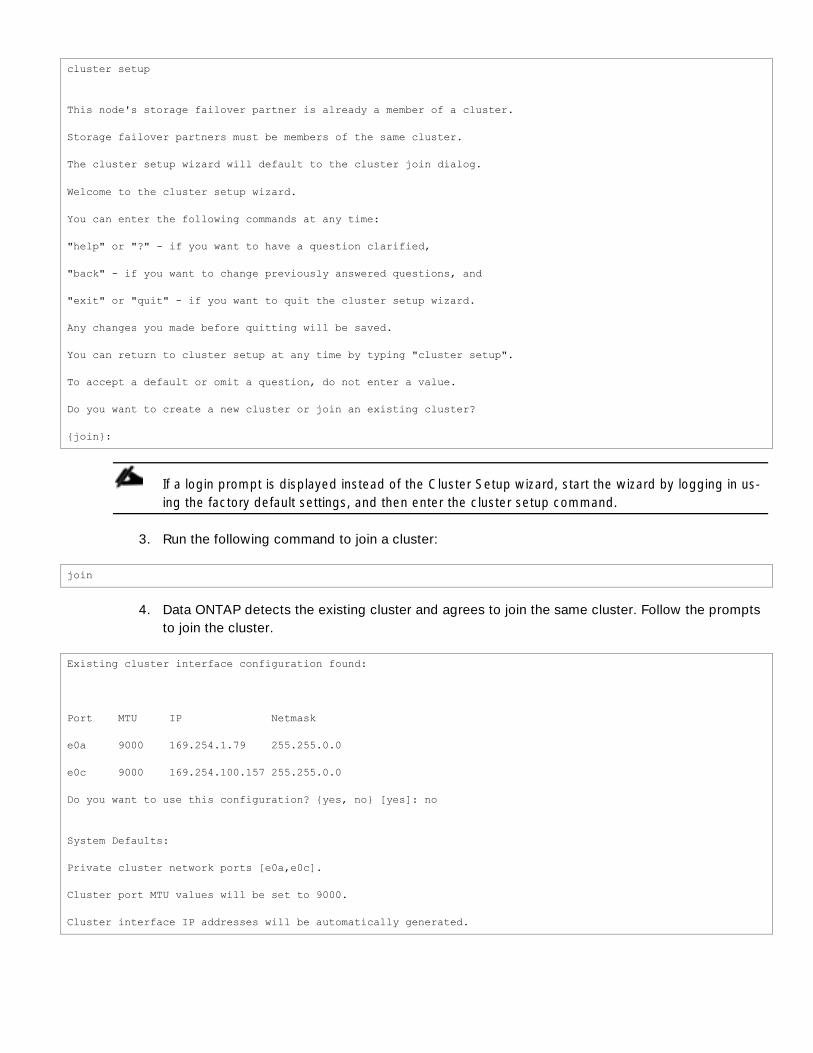
cluster setup
This node's storage failover partner is already a member of a cluster.
Storage failover partners must be members of the same cluster.
The cluster setup wizard will default to the cluster join dialog.
Welcome to the cluster setup wizard.
You can enter the following commands at any time:
"help" or "?" - if you want to have a question clarified,
"back" - if you want to change previously answered questions, and
"exit" or "quit" - if you want to quit the cluster setup wizard.
Any changes you made before quitting will be saved.
You can return to cluster setup at any time by typing "cluster setup".
To accept a default or omit a question, do not enter a value.
Do you want to create a new cluster or join an existing cluster?
{join}:
If a login prompt is displayed instead of the Cluster Setup wizard, start the wizard by logging in us-
ing the factory default settings, and then enter the cluster setup command.
3. Run the following command to join a cluster:
join
4. Data ONTAP detects the existing cluster and agrees to join the same cluster. Follow the prompts
to join the cluster.
Existing cluster interface configuration found:
Port MTU IP Netmask
e0a 9000 169.254.1.79 255.255.0.0
e0c 9000 169.254.100.157 255.255.0.0
Do you want to use this configuration? {yes, no} [yes]: no
System Defaults:
Private cluster network ports [e0a,e0c].
Cluster port MTU values will be set to 9000.
Cluster interface IP addresses will be automatically generated.

If four ports are being used for the switchless cluster interconnect, enter e0a, e0b, e0c, and e0d
for the private cluster network ports above.
Do you want to use these defaults? {yes, no} [yes]:Enter
It can take several minutes to create cluster interfaces...
5. The steps to join a cluster are displayed.
Step 1 of 3: Join an Existing Cluster
You can type "back", "exit", or "help" at any question.
Enter the name of the cluster you would like to join [<clustername>]:Enter
Joining cluster <clustername>
Starting cluster support services ..
This node has joined the cluster <<var_clustername>>.
Step 2 of 3: Configure Storage Failover (SFO)
You can type "back", "exit", or "help" at any question.
SFO is enabled.
Step 3 of 3: Set Up the Node
You can type "back", "exit", or "help" at any question.
Notice: HA is configured in management.
The node should find the cluster name. Cluster joining can take a few minutes.
6. Set up the node.
Enter the node management interface port [e0M]: e0M
Enter the node management interface IP address [<node02-mgmt-ip>]: Enter
Enter the node management interface netmask [<node02-netmask>]: Enter
Enter the node management interface default gateway [<node02-gw>]: Enter
The node management interface has been modified to use port e0M with IP address <node02-mgmt-ip>.

This system will send event messages and weekly reports to NetApp Technical Support.
To disable this feature, enter "autosupport modify -support disable" within 24 hours.
Enabling AutoSupport can significantly speed problem determination and resolution should a problem occur on
your system.
For further information on AutoSupport, please see: http://support.netapp.com/autosupport/
Press enter to continue: Enter
This node has been joined to cluster "<clustername>".
To complete cluster setup, you must join each additional node to the cluster by running "cluster setup" on
each node.
Once all nodes have been joined to the cluster, see the Clustered Data ONTAP Software Setup Guide for
information about additional system configuration tasks. You can find the Software Setup Guide on the NetApp
Support Site.
To complete system configuration, you can use either OnCommand System Manager or the Data ONTAP command-line
interface.
To access OnCommand System Manager, point your web browser to the cluster management IP address
(<clustermgmt-ip>).
To access the command-line interface, connect to the cluster management IP address (for example, ssh
admin@<clustermgmt-ip>).
The node management interface can be on the same subnet as the cluster management interface,
or it can be on a different subnet. In this document, we assume that it is on the same subnet.
Log In to the Cluster
To log in to the cluster, complete the following steps:
1. Open an SSH connection to either the cluster IP or host name.
2. Log in to the admin user with the password you provided earlier.
Zero All Spare Disks
To zero all spare disks in the cluster, run the following command:
disk zerospares
Advanced Data Partitioning should have created a root partition and two data partitions on each SSD drive
in an All Flash FAS configuration. Disk autoassign should have assigned one data partition to each node in
an HA Pair. If a different disk assignment is required, disk autoassignment must be disabled on both nodes
in the HA pair by running the disk option modify command. Spare partitions can then be moved from
one node to another by running the disk removeowner and disk assign commands.

Set Onboard Unified Target Adapter 2 Port Personality
To set the personality of the onboard unified target adapter 2 (UTA2), complete the following steps:
1. Verify the Current Mode and Current Type properties of the ports by running the ucadmin show
command.
ucadmin show
Current Current Pending Pending Admin
Node Adapter Mode Type Mode Type Status
------------ ------- ------- --------- ------- --------- -----------
<st-node01>
0e fc target - - online
<st-node01>
0f fc target - - online
<st-node01>
0g cna target - - online
<st-node01>
0h cna target - - online
<st-node02>
0e fc target - - online
<st-node02>
0f fc target - - online
<st-node02>
0g cna target - - online
<st-node02>
0h cna target - - online
8 entries were displayed.
2. Verify that the Current Mode and Current Type properties for all ports are set properly. Set ports
used for Fibre Channel (FC) connectivity to mode fc; otherwise, set them to the mode cna. That
includes FCoE ports, which should be set to the mode cna. The port type for all protocols should
be set to target. Change the port personality with the following command:
ucadmin modify -node <home-node-of-the-port> -adapter <port-name> -mode {fc|cna} -type target
The ports must be offline to run this command. To take an adapter offline, run the fcp adapter
modify –node <home-node-of-the-port> -adapter <port-name> -state down com-

mand. Ports must be converted in pairs (for example, 0e and 0f). After conversion, a reboot is re-
quired, and the ports must be brought back to the up state.
Set Auto-Revert on Cluster Management
To set the auto-revert parameter on the cluster management interface, complete the following step:
A storage virtual machine (SVM) is referred to as a Vserver (or vserver) in the GUI and CLI.
Run the following command:
network interface modify –vserver <clustername> -lif cluster_mgmt –auto-revert true
Set Up Management Broadcast Domain
By default, all network ports are included in the default broadcast domain. Network ports used for data
services (for example, e0b, e0d, e0g, e0h, e0j, e0k, and e0l) should be removed from the default
broadcast domain, leaving just the management network ports (e0i and e0M). To perform this task, run the
following commands:
broadcast-domain remove-ports –broadcast-domain Default –ports <st-node01>:e0b,<st-node01>:e0d, <st-
node01>:e0g,<st-node01>:e0h,<st-node01>:e0j,<st-node01>:e0k,<st-node01>:e0l,<st-node02>:e0b,<st-
node02>:e0d,<st-node02>:e0g,<st-node02>:e0h,<st-node02>:e0j,<st-node02>:e0k,<st-node02>:e0l
broadcast-domain show
Set Up Service Processor Network Interface
To assign a static IPv4 address to the service processor on each node, run the following commands:
system service-processor network modify –node <st-node01> -address-family IPv4 –enable true –dhcp none –ip-
address <node01-sp-ip> -netmask <node01-sp-mask> -gateway <node01-sp-gateway>
system service-processor network modify –node <st-node02> -address-family IPv4 –enable true –dhcp none –ip-
address <node02-sp-ip> -netmask <node02-sp-mask> -gateway <node02-sp-gateway>
The service processor IP addresses should be in the same subnet as the node management IP addresses.
Create Aggregates
An aggregate containing the root volume is created during the ONTAP setup process. To create additional
aggregates, determine the aggregate name, the node on which to create it, and the number of disks it
contains.
To create new aggregates, complete the following steps:
1. Run the following commands:
aggr create -aggregate aggr1_node01 -node <st-node01> -diskcount <num-disks>
aggr create -aggregate aggr1_node02 -node <st-node02> -diskcount <num-disks>

You should have the minimum number of hot spare disks for hot spare disk partitions recommend-
ed for your aggregate
For all flash aggregates, you should have a minimum of one hot spare disk or disk partition. For
nonflash homogenous aggregates, you should have a minimum of two hot spare disks or disk par-
titions. For Flash Pool aggregates, you should have a minimum of two hot spare disks or disk parti-
tions for each disk type.
Start with five disks initially; you can add disks to an aggregate when additional storage is required.
In an AFF configuration with a small number of SSDs, you might want to create an aggregate with
all but one remaining disk (spare) assigned to the controller.
The aggregate cannot be created until disk zeroing completes. Run the aggr show command to
display aggregate creation status. Do not proceed until both aggr1_node1 and aggr1_node2 are
online.
2. Rename the root aggregate on node 01 to match the naming convention for this aggregate on
node 02.
aggr show
aggr rename –aggregate aggr0 –newname <node01-rootaggrname>
Verify Storage Failover
To confirm that storage failover is enabled, run the following commands for a failover pair:
1. Verify the status of storage failover.
storage failover show
Both <st-node01> and <st-node02> must be capable of performing a takeover. Continue with
step 3 if the nodes are capable of performing a takeover.
2. Enable failover on one of the two nodes.
storage failover modify -node <st-node01> -enabled true
Enabling failover on one node enables it for both nodes.
3. Verify the HA status for a two-node cluster.
This step is not applicable for clusters with more than two nodes.
cluster ha show

4. Continue with step 6 if high availability is configured.
5. Only enable HA mode for two-node clusters. Do not run this command for clusters with more
than two nodes because it causes problems with failover.
cluster ha modify -configured true
Do you want to continue? {y|n}: y
6. Verify that hardware assist is correctly configured and, if needed, modify the partner IP address.
storage failover hwassist show
storage failover modify –hwassist-partner-ip <node02-mgmt-ip> -node <st-node01>
storage failover modify –hwassist-partner-ip <node01-mgmt-ip> -node <st-node02>
Disable Flow Control on 10GE Ports
NetApp recommends disabling flow control on all of the 10GbE and UTA2 ports that are connected to
external devices. To disable flow control, complete the following steps:
1. Run the following commands to configure node 01:
network port modify -node <st-node01> -port e0b,e0d,e0e,e0f,e0g,e0h -flowcontrol-admin none
Warning: Changing the network port settings will cause a several second interruption in carrier.
Do you want to continue? {y|n}: y
2. Run the following commands to configure node 02:
network port modify -node <st-node02> -port e0b,e0d,e0e,e0f,e0g,e0h -flowcontrol-admin none
Warning: Changing the network port settings will cause a several second interruption in carrier.
Do you want to continue? {y|n}: y
network port show –fields flowcontrol-admin
Disable Unused FCoE Capability on CNA Ports
If a UTA2 port is set to CNA mode and is only expected to handle Ethernet data traffic (for example NFS),
then the unused FCoE capability of the port should be disabled by setting the corresponding FCP adapter to
state down with the fcp adapter modify command. Here are some examples:
fcp adapter modify -node <st-node01> -adapter 0g –state down
fcp adapter modify -node <st-node01> -adapter 0h –state down
fcp adapter modify -node <st-node02> -adapter 0g –state down
fcp adapter modify -node <st-node02> -adapter 0h –state down
fcp adapter show –fields state

Configure Network Time Protocol
To configure time synchronization on the cluster, complete the following steps:
1. Set the time zone for the cluster.
timezone <timezone>
For example, in the eastern United States, the time zone is America/New_York.
2. Set the date for the cluster.
date <ccyymmddhhmm.ss>
The format for the date is <[Century][Year][Month][Day][Hour][Minute].[Second]> (for example,
201309081735.17).
3. Configure the Network Time Protocol (NTP) servers for the cluster.
cluster time-service ntp server create -server <switch-a-ntp-ip>
cluster time-service ntp server create -server <switch-b-ntp-ip>
Configure Simple Network Management Protocol
To configure the Simple Network Management Protocol (SNMP), complete the following steps:
1. Configure basic SNMP information, such as the location and contact. When polled, this infor-
mation is visible as the sysLocation and sysContact variables in SNMP.
snmp contact <snmp-contact>
snmp location “<snmp-location>”
snmp init 1
options snmp.enable on
2. Configure SNMP traps to send to remote hosts, such as a DFM server or another fault manage-
ment system.
snmp traphost add <oncommand-um-server-fqdn>
Configure SNMPv1 Access
To configure SNMPv1 access, set the shared, secret plain-text password (called a community):
snmp community add ro <snmp-community>

Configure AutoSupport
NetApp AutoSupport® sends support summary information to NetApp through HTTPS. To configure
AutoSupport, run the following command:
system node autosupport modify -node * -state enable –mail-hosts <mailhost> -transport https -support enable
-noteto <storage-admin-email>
Enable Cisco Discovery Protocol
To enable the Cisco Discovery Protocol (CDP) on the NetApp storage controllers, run the following
command to enable CDP on ONTAP:
node run -node * options cdpd.enable on
To be effective, CDP must also be enabled on directly connected networking equipment such as switches
and routers.
Create Broadcast Domains in Data ONTAP
To create a data broadcast domains for Container Management and NFS on ONTAP:
broadcast-domain create –broadcast-domain Cntr-MGMT –mtu 1500
broadcast-domain create -broadcast-domain Cntr-MGMT-NFS -mtu 9000
Create Interface Groups
To create the LACP interface groups for the 10GbE data interfaces, run the following commands:
ifgrp create -node <st-node01> -ifgrp a0a -distr-func port -mode multimode_lacp
ifgrp add-port -node <st-node01> -ifgrp a0a -port e0b
ifgrp add-port -node <st-node01> -ifgrp a0a -port e0d
ifgrp create -node <st-node02> -ifgrp a0a -distr-func port -mode multimode_lacp
ifgrp add-port -node <st-node02> -ifgrp a0a -port e0b
ifgrp add-port -node <st-node02> -ifgrp a0a -port e0d
ifgrp show
Create VLANs
To create VLANs, create Container Management and NFS VLAN ports and add them to the appropriate
broadcast domain:
network port modify –node <st-node01> -port a0a –mtu 9000
network port modify –node <st-node02> -port a0a –mtu 9000
network port vlan create –node <st-node01> -vlan-name a0a-<ctnr-mgmt-vlan-id>
network port vlan create –node <st-node02> -vlan-name a0a-<ctnr-mgmt-vlan-id>
network port vlan create –node <st-node01> -vlan-name a0a-<ctnr-mgmt-nfs-vlan-id>
network port vlan create –node <st-node02> -vlan-name a0a-<ctnr-mgmt-nfs-vlan-id>

broadcast-domain add-ports -broadcast-domain Cntr-MGMT -ports <st-node01>:a0a-<ctnr-mgmt-vlan-id>, <st-
node02>:a0a-<ctnr-mgmt-vlan-id>
broadcast-domain add-ports -broadcast-domain Cntr-NFS -ports <st-node01>:a0a-<ctnr-mgmt-nfs-vlan-id>, <st-
node02>:a0a-<ctnr-mgmt-nfs-vlan-id>
Create Docker Infrastructure Storage Virtual Machine
To create an infrastructure SVM, complete the following steps:
1. Run the vserver create command.
vserver create –vserver Container-SVM –rootvolume rootvol –aggregate aggr1_node01 –rootvolume-security-style
unix
2. Select the SVM data protocols to configure, keeping fcp and nfs.
vserver remove-protocols –vserver Container-SVM -protocols iscsi,cifs,ndmp
3. Add the two data aggregates to the Container-SVM aggregate list.
vserver modify –vserver Container-SVM –aggr-list aggr1_node01,aggr1_node02
4. Enable and run the NFS protocol in the Container-SVM.
nfs create -vserver Container-SVM -udp disabled
Create Load-Sharing Mirrors of SVM Root Volume
To create a load-sharing mirror of an SVM root volume, complete the following steps:
1. Create a volume to be the load-sharing mirror of the infrastructure SVM root volume on each
node.
volume create –vserver Container-SVM –volume rootvol_m01 –aggregate aggr1_node01 –size 1GB –type DP
volume create –vserver Container-SVM –volume rootvol_m02 –aggregate aggr1_node02 –size 1GB –type DP
2. Create a job schedule to update the root volume mirror relationships every 15 minutes.
job schedule interval create -name 15min -minutes 15
3. Create the mirroring relationships.
snapmirror create –source-path Container-SVM:rootvol –destination-path Container-SVM:rootvol_m01 –type LS -
schedule 15min
snapmirror create –source-path Container-SVM:rootvol –destination-path Container-SVM:rootvol_m02 –type LS -
schedule 15min
4. Initialize the mirroring relationship.
snapmirror initialize-ls-set –source-path Container-SVM:rootvol
snapmirror show
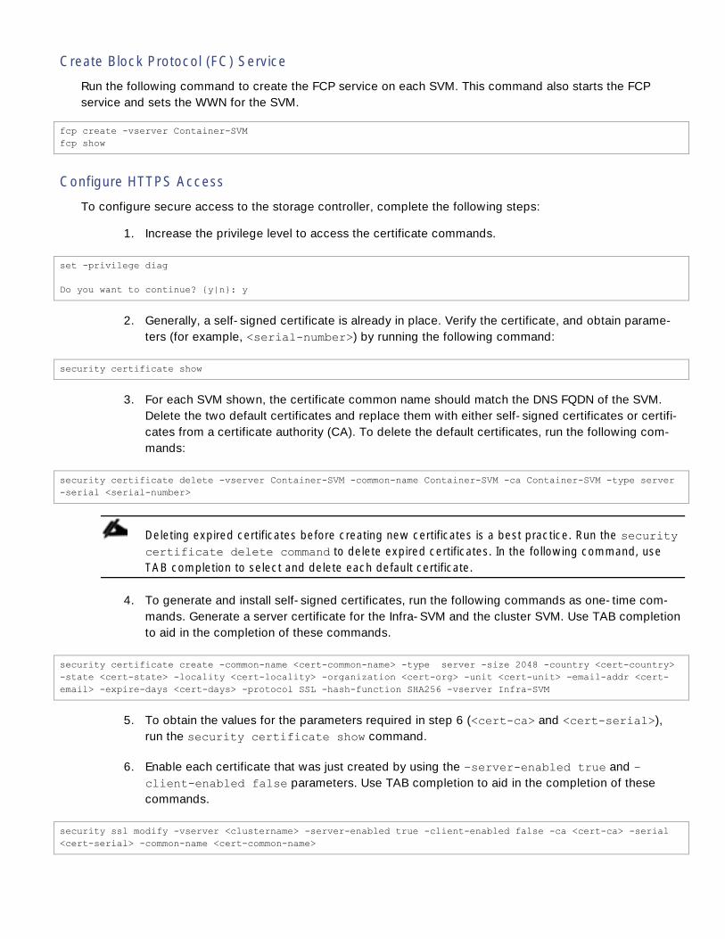
Create Block Protocol (FC) Service
Run the following command to create the FCP service on each SVM. This command also starts the FCP
service and sets the WWN for the SVM.
fcp create -vserver Container-SVM
fcp show
Configure HTTPS Access
To configure secure access to the storage controller, complete the following steps:
1. Increase the privilege level to access the certificate commands.
set -privilege diag
Do you want to continue? {y|n}: y
2. Generally, a self-signed certificate is already in place. Verify the certificate, and obtain parame-
ters (for example, <serial-number>) by running the following command:
security certificate show
3. For each SVM shown, the certificate common name should match the DNS FQDN of the SVM.
Delete the two default certificates and replace them with either self-signed certificates or certifi-
cates from a certificate authority (CA). To delete the default certificates, run the following com-
mands:
security certificate delete -vserver Container-SVM -common-name Container-SVM -ca Container-SVM -type server
-serial <serial-number>
Deleting expired certificates before creating new certificates is a best practice. Run the security
certificate delete command to delete expired certificates. In the following command, use
TAB completion to select and delete each default certificate.
4. To generate and install self-signed certificates, run the following commands as one-time com-
mands. Generate a server certificate for the Infra-SVM and the cluster SVM. Use TAB completion
to aid in the completion of these commands.
security certificate create -common-name <cert-common-name> -type server -size 2048 -country <cert-country>
-state <cert-state> -locality <cert-locality> -organization <cert-org> -unit <cert-unit> -email-addr <cert-
email> -expire-days <cert-days> -protocol SSL -hash-function SHA256 -vserver Infra-SVM
5. To obtain the values for the parameters required in step 6 (<cert-ca> and <cert-serial>),
run the security certificate show command.
6. Enable each certificate that was just created by using the –server-enabled true and –
client-enabled false parameters. Use TAB completion to aid in the completion of these
commands.
security ssl modify -vserver <clustername> -server-enabled true -client-enabled false -ca <cert-ca> -serial
<cert-serial> -common-name <cert-common-name>

It is normal for some of these commands to return an error message stating that the entry does not
exist.
7. Change back to the normal admin privilege level and set up the system to allow SVM logs to be
available by web.
set –privilege admin
vserver services web modify –name spi|ontapi|compat –vserver * -enabled true
Configure NFSv3
To configure NFSv3 on the SVM, complete the following steps:
1. Create a new rule for the infrastructure NFS subnet in the default export policy.
vserver export-policy rule create –vserver Container-SVM -policyname default –ruleindex 1 –protocol nfs -
clientmatch <cntr-nfs-subnet-cidr> -rorule sys –rwrule sys -superuser sys –allow-suid false
2. Assign the FlexPod export policy to the infrastructure SVM root volume.
volume modify –vserver Container-SVM –volume rootvol –policy default
Create FlexVol Volumes
The following information is required to create a NetApp FlexVol® volume:
The volume name
The volume size
The aggregate on which the volume exists
To create a FlexVol volume, run the following commands:
volume create -vserver Container-SVM -volume Linux_Boot -aggregate aggr1_node01 -size 1200GB -state online -
policy default -space-guarantee none -percent-snapshot-space 0
volume create -vserver Container-SVM -volume Docker_Data_LUNs -aggregate aggr1_node02 -size 3TB -state online
-policy default -space-guarantee none -percent-snapshot-space 0
volume create -vserver Container-SVM -volume DTR_NFS -aggregate aggr1_node01 -size 1TB -state online -policy
default -junction-path /DTR-NFS -space-guarantee none -percent-snapshot-space 0
snapmirror update-ls-set -source-path Container-SVM:rootvol
Create Boot LUNs
To create ten boot LUNs, run the following commands:

lun create -vserver Container-SVM -volume Linux_Boot -lun Docker_Host_01 -size 60GB -ostype linux -space-
reserve disabled
lun create -vserver Container-SVM -volume Linux_Boot -lun Docker_Host_02 -size 60GB -ostype linux -space-
reserve disabled
lun create -vserver Container-SVM -volume Linux_Boot -lun Docker_Host_03 -size 60GB -ostype linux -space-
reserve disabled
lun create -vserver Container-SVM -volume Linux_Boot -lun Docker_Host_04 -size 60GB -ostype linux -space-
reserve disabled
lun create -vserver Container-SVM -volume Linux_Boot -lun Docker_Host_05 -size 60GB -ostype linux -space-
reserve disabled
lun create -vserver Container-SVM -volume Linux_Boot -lun Docker_Host_06 -size 60GB -ostype linux -space-
reserve disabled
lun create -vserver Container-SVM -volume Linux_Boot -lun Docker_Host_07 -size 60GB -ostype linux -space-
reserve disabled
lun create -vserver Container-SVM -volume Linux_Boot -lun Docker_Host_08 -size 60GB -ostype linux -space-
reserve disabled
lun create -vserver Container-SVM -volume Linux_Boot -lun Docker_Host_09 -size 60GB -ostype linux -space-
reserve disabled
lun create -vserver Container-SVM -volume Linux_Boot -lun Docker_Host_10 -size 60GB -ostype linux -space-
reserve disabled
Create Docker Data LUNs
To create ten boot LUNs, run the following commands:
lun create -vserver Container-SVM -volume Docker_Data_LUNs -lun Docker_Host_01 -size 300GB -ostype linux -
space-reserve disabled
lun create -vserver Container-SVM -volume Docker_Data_LUNs -lun Docker_Host_02 -size 300GB -ostype linux -
space-reserve disabled
lun create -vserver Container-SVM -volume Docker_Data_LUNs -lun Docker_Host_03 -size 300GB -ostype linux -
space-reserve disabled
lun create -vserver Container-SVM -volume Docker_Data_LUNs -lun Docker_Host_04 -size 300GB -ostype linux -
space-reserve disabled
lun create -vserver Container-SVM -volume Docker_Data_LUNs -lun Docker_Host_05 -size 300GB -ostype linux -
space-reserve disabled
lun create -vserver Container-SVM -volume Docker_Data_LUNs -lun Docker_Host_06 -size 300GB -ostype linux -
space-reserve disabled
lun create -vserver Container-SVM -volume Docker_Data_LUNs -lun Docker_Host_07 -size 300GB -ostype linux -
space-reserve disabled
lun create -vserver Container-SVM -volume Docker_Data_LUNs -lun Docker_Host_08 -size 300GB -ostype linux -
space-reserve disabled
lun create -vserver Container-SVM -volume Docker_Data_LUNs -lun Docker_Host_09 -size 300GB -ostype linux -
space-reserve disabled
lun create -vserver Container-SVM -volume Docker_Data_LUNs -lun Docker_Host_10 -size 300GB -ostype linux -
space-reserve disabled

Schedule Deduplication
On NetApp All Flash FAS systems, deduplication is enabled by default. To schedule deduplication, complete
the following steps:
After the volumes are created, assign a once-a-day deduplication schedule to all volumes.
efficiency modify –vserver Container-SVM –volume Linux_Boot –schedule sun-sat@0
efficiency modify –vserver Container-SVM –volume Docker_Data_LUNs –schedule sun-sat@0
efficiency modify –vserver Container-SVM –volume DTR_NFS –schedule sun-sat@0
Create FCP LIFs
Run the following commands to create four FCP LIFs (two on each node) per attached fabric interconnect:
network interface create -vserver Container-SVM -lif fcp_lif01a -role data -data-protocol fcp -home-node <st-
node01> -home-port 0e –status-admin up
network interface create -vserver Container-SVM -lif fcp_lif01b -role data -data-protocol fcp -home-node <st-
node01> -home-port 0f –status-admin up
network interface create -vserver Container-SVM -lif fcp_lif02a -role data -data-protocol fcp -home-node <st-
node02> -home-port 0e –status-admin up
network interface create -vserver Container-SVM -lif fcp_lif02b -role data -data-protocol fcp -home-node <st-
node02> -home-port 0f –status-admin up
network interface show
Create NFS LIFs
To create NFS LIFs, run the following commands:
network interface create -vserver Container-SVM -lif nfs_lif01 -role data -data-protocol nfs -home-node <st-
node01> -home-port a0a-<cntr-mgmt-nfs-vlan-id> –address <node01-cntr-mgmt-nfs-ip> -netmask <node01-cntr-mgmt-
nfs-mask> -status-admin up –failover-policy broadcast-domain-wide –firewall-policy data –auto-revert true
network interface create -vserver Container-SVM -lif nfs_lif02 -role data -data-protocol nfs -home-node <st-
node02> -home-port a0a-<cntr-mgmt-nfs-vlan-id> –address <node02-cntr-mgmt-nfs-ip> -netmask <node02-cntr-mgmt-
nfs-mask> -status-admin up –failover-policy broadcast-domain-wide –firewall-policy data –auto-revert true
network interface show

Add Infrastructure SVM Administrator
To add the infrastructure SVM administrator and SVM administration LIF in the out-of-band management
network, complete the following steps:
1. Run the following commands:
network interface create –vserver Container-SVM –lif svm-mgmt –role data –data-protocol none –home-node <st-
node02> -home-port a0a-<cntr-mgmt-vlan-id> –address <svm-mgmt-ip> -netmask <svm-mgmt-mask> -status-admin up
–failover-policy broadcast-domain-wide –firewall-policy mgmt –auto-revert true
2. Create a default route to allow the SVM management interface to reach the outside world.
network route create –vserver Container-SVM -destination 0.0.0.0/0 –gateway <svm-mgmt-gateway>
network route show
3. Set a password for the SVM vsadmin user and unlock the user.
security login password –username vsadmin –vserver Container-SVM
Enter a new password: <password>
Enter it again: <password>
security login unlock –username vsadmin –vserver Container-SVM
Create Broadcast Domain for Container Tenant A
To create a data broadcast domain for the first Container Tenant and NFS on ONTAP:
broadcast-domain create -broadcast-domain Cntr-TNT-A-NFS -mtu 9000
Create VLAN Interfaces for Container Tenant A
To create VLAN interfaces for Container Tenant A and add them to the appropriate broadcast domain:
network port vlan create –node <st-node01> -vlan-name a0a-<ctnr-tnt-a-nfs-vlan-id>
network port vlan create –node <st-node02> -vlan-name a0a-<ctnr-tnt-a-nfs-vlan-id>
broadcast-domain add-ports -broadcast-domain Cntr-TNT-A-NFS -ports <st-node01>:a0a-<ctnr-tnt-a-nfs-vlan-id>,
<st-node02>:a0a-<ctnr-tnt-a-nfs-vlan-id>
Create Docker Tenant Storage Virtual Machine
To create a tenant SVM, complete the following steps:
1. Run the vserver create command.
vserver create –vserver Cntr-TNT-A-SVM –rootvolume rootvol –aggregate aggr1_node02 –rootvolume-security-style
unix

2. Create a max volume limit on the tenant SVM (optional)
vserver modify –vserver Cntr-TNT-A-SVM –max-volumes 50
3. Select the SVM data protocols to configure, keeping only nfs.
vserver remove-protocols –vserver Cntr-TNT-A-SVM -protocols iscsi,fcp,cifs,ndmp
4. Add the two data aggregates to the Container-SVM aggregate list.
vserver modify –vserver Cntr-TNT-A-SVM –aggr-list aggr1_node01,aggr1_node02
5. Enable and run the NFS protocol in the Cntr-TNT-A-SVM.
nfs create -vserver Cntr-TNT-A-SVM -udp disabled
Create Load-Sharing Mirrors of Tenant SVM Root Volume
To create a load-sharing mirror of an SVM root volume, complete the following steps:
1. Create a volume to be the load-sharing mirror of the infrastructure SVM root volume on each
node.
volume create –vserver Cntr-TNT-A-SVM –volume rootvol_m01 –aggregate aggr1_node01 –size 1GB –type DP
volume create –vserver Cntr-TNT-A-SVM –volume rootvol_m02 –aggregate aggr1_node02 –size 1GB –type DP
2. Create the mirroring relationships.
snapmirror create –source-path Cntr-TNT-A-SVM:rootvol –destination-path Cntr-TNT-A-SVM:rootvol_m01 –type LS -
schedule 15min
snapmirror create –source-path Container-SVM:rootvol –destination-path Cntr-TNT-A-SVM:rootvol_m02 –type LS -
schedule 15min
3. Initialize the mirroring relationship.
snapmirror initialize-ls-set –source-path Cntr-TNT-A-SVM:rootvol
snapmirror show
Configure Secure Access to Cntr-TNT-A-SVM
To configure secure access to the storage controller, complete the following steps:
1. Increase the privilege level to access the certificate commands.
set -privilege diag
Do you want to continue? {y|n}: y

2. Generally, a self-signed certificate is already in place. Verify the certificate, and obtain parame-
ters (for example, <serial-number>) by running the following command:
security certificate show
3. For each SVM shown, the certificate common name should match the DNS FQDN of the SVM.
Delete the two default certificates and replace them with either self-signed certificates or certifi-
cates from a certificate authority (CA). To delete the default certificates, run the following com-
mands:
security certificate delete -vserver Cntr-TNT-A-SVM -common-name <cert-common-name> -ca <cert-common-name>-
type server -serial <serial-number>
Deleting expired certificates before creating new certificates is a best practice. Run the security
certificate delete command to delete expired certificates. In the following command, use
TAB completion to select and delete each default certificate.
4. To generate and install self-signed certificates, run the following commands as one-time com-
mands. Generate a server certificate for the Infra-SVM and the cluster SVM. Use TAB completion
to aid in the completion of these commands.
security certificate create -common-name <cert-common-name> -type server -size 2048 -country <cert-country>
-state <cert-state> -locality <cert-locality> -organization <cert-org> -unit <cert-unit> -email-addr <cert-
email> -expire-days <cert-days> -protocol SSL -hash-function SHA256 -vserver Cntr-TNT-A-SVM
5. To obtain the values for the parameters required in step 6 (<cert-ca> and <cert-serial>),
run the security certificate show command.
6. Enable each certificate that was just created by using the –server-enabled true and –
client-enabled false parameters. Use TAB completion to aid in the completion of these
commands.
security ssl modify -vserver Cntr-TNT-A-SVM -server-enabled true -client-enabled false -ca <cert-ca> -serial
<cert-serial> -common-name <cert-common-name>
It is normal for some of these commands to return an error message stating that the entry does not
exist.
7. Change back to the normal admin privilege level and set up the system to allow SVM logs to be
available by web.
set –privilege admin
vserver services web modify –name spi|ontapi|compat –vserver * -enabled true
Configure NFSv3 in Cntr-TNT-A-SVM
To configure NFSv3 on the SVM, complete the following steps:
1. Create a new rule for the infrastructure NFS subnet in the default export policy.

vserver export-policy rule create –vserver Cntr-TNT-A-SVM -policyname default –ruleindex 1 –protocol nfs -
clientmatch <cntr-tnt-a-nfs-subnet-cidr> -rorule sys –rwrule sys -superuser sys –allow-suid false
2. Assign the FlexPod export policy to the infrastructure SVM root volume.
volume modify –vserver Cntr-TNT-A-SVM –volume rootvol –policy default
Create NFS LIFs in Cntr-TNT-A-SVM
To create NFS LIFs, run the following commands:
network interface create -vserver Cntr-TNT-A-SVM -lif nfs_lif01 -role data -data-protocol nfs -home-node <st-
node01> -home-port a0a-<cntr-tnt-a-nfs-vlan-id> –address <node01-cntr-tnt-a-nfs-ip> -netmask <node01-cntr-
tnt-a-nfs-mask> -status-admin up –failover-policy broadcast-domain-wide –firewall-policy data –auto-revert
true
network interface create -vserver Cntr-TNT-A-SVM -lif nfs_lif02 -role data -data-protocol nfs -home-node <st-
node02> -home-port a0a-<cntr-tnt-a-nfs-vlan-id> –address <node02-cntr-tnt-a-nfs-ip> -netmask <node02-cntr-
tnt-a-nfs-mask> -status-admin up –failover-policy broadcast-domain-wide –firewall-policy data –auto-revert
true
network interface show
Add Cntr-TNT-A-SVM Administrator and NetApp Volume Plugin (nDVP) User
To add the Cntr-TNT-A-SVM administrator, nDCP user, and SVM administration LIF in the Container
management network, complete the following steps:
1. Run the following commands:
network interface create –vserver Cntr-TNT-A-SVM –lif svm-mgmt –role data –data-protocol none –home-node <st-
node02> -home-port a0a-<cntr-mgmt-vlan-id> –address <svm-mgmt-ip> -netmask <svm-mgmt-mask> -status-admin up
–failover-policy broadcast-domain-wide –firewall-policy mgmt –auto-revert true
2. Create a default route to allow the SVM management interface to reach the outside world.
network route create –vserver Cntr-TNT-A-SVM -destination 0.0.0.0/0 –gateway <svm-mgmt-gateway>
network route show
3. Create a nDVP role
#Create a new nDVP role
security login role create –vserver Cntr-TNT-A-SVM –role ndvp_role –cmddirname DEFAULT –access none
#Grant nDVP persmissions
security login role create -vserver Cntr-TNT-A-SVM -role ndvp_role -cmddirname "event generate-autosupport-
log" -access all
security login role create -vserver Cntr-TNT-A-SVM -role ndvp_role -cmddirname "network interface" -access
readonly
security login role create -vserver Cntr-TNT-A-SVM -role ndvp_role -cmddirname "version" -access readonly
security login role create -vserver Cntr-TNT-A-SVM -role ndvp_role -cmddirname "vserver" -access readonly
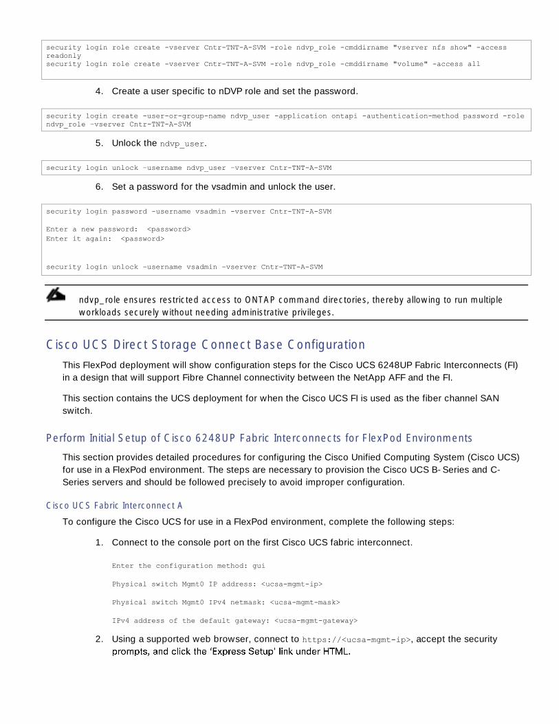
security login role create -vserver Cntr-TNT-A-SVM -role ndvp_role -cmddirname "vserver nfs show" -access
readonly
security login role create -vserver Cntr-TNT-A-SVM -role ndvp_role -cmddirname "volume" -access all
4. Create a user specific to nDVP role and set the password.
security login create -user-or-group-name ndvp_user -application ontapi -authentication-method password -role
ndvp_role –vserver Cntr-TNT-A-SVM
5. Unlock the ndvp_user.
security login unlock –username ndvp_user –vserver Cntr-TNT-A-SVM
6. Set a password for the vsadmin and unlock the user.
security login password –username vsadmin -vserver Cntr-TNT-A-SVM
Enter a new password: <password>
Enter it again: <password>
security login unlock –username vsadmin –vserver Cntr-TNT-A-SVM
ndvp_role ensures restricted access to ONTAP command directories, thereby allowing to run multiple
workloads securely without needing administrative privileges.
Cisco UCS Direct Storage Connect Base Configuration
This FlexPod deployment will show configuration steps for the Cisco UCS 6248UP Fabric Interconnects (FI)
in a design that will support Fibre Channel connectivity between the NetApp AFF and the FI.
This section contains the UCS deployment for when the Cisco UCS FI is used as the fiber channel SAN
switch.
Perform Initial Setup of Cisco 6248UP Fabric Interconnects for FlexPod Environments
This section provides detailed procedures for configuring the Cisco Unified Computing System (Cisco UCS)
for use in a FlexPod environment. The steps are necessary to provision the Cisco UCS B-Series and C-
Series servers and should be followed precisely to avoid improper configuration.
Cisco UCS Fabric Interconnect A
To configure the Cisco UCS for use in a FlexPod environment, complete the following steps:
1. Connect to the console port on the first Cisco UCS fabric interconnect.
Enter the configuration method: gui
Physical switch Mgmt0 IP address: <ucsa-mgmt-ip>
Physical switch Mgmt0 IPv4 netmask: <ucsa-mgmt-mask>
IPv4 address of the default gateway: <ucsa-mgmt-gateway>
2. Using a supported web browser, connect to https://<ucsa-mgmt-ip>, accept the security

3. Select Initial Setup and click Submit.
4. Select Enable clustering, Fabric A, and IPv4.
5. Fill in the Virtual IP Address with the UCS cluster IP.
6. Completely fill in the System setup section. For system name, use the overall UCS system name.
For the Mgmt IP Address, use <ucsa-mgmt-ip>.
7. Click Submit.
Cisco UCS Fabric Interconnect B
To configure the Cisco UCS for use in a FlexPod environment, complete the following steps:
1. Connect to the console port on the second Cisco UCS fabric interconnect.
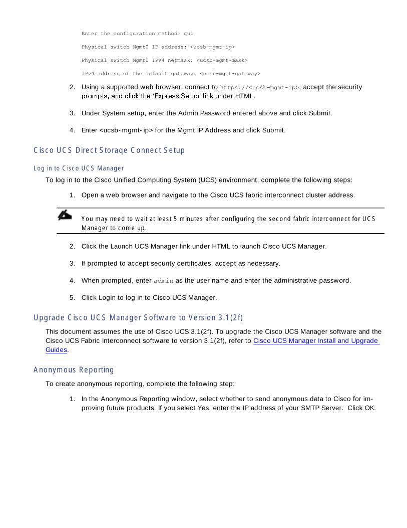
Enter the configuration method: gui
Physical switch Mgmt0 IP address: <ucsb-mgmt-ip>
Physical switch Mgmt0 IPv4 netmask: <ucsb-mgmt-mask>
IPv4 address of the default gateway: <ucsb-mgmt-gateway>
2. Using a supported web browser, connect to https://<ucsb-mgmt-ip>, accept the security
der HTML.
3. Under System setup, enter the Admin Password entered above and click Submit.
4. Enter <ucsb-mgmt-ip> for the Mgmt IP Address and click Submit.
Cisco UCS Direct Storaqe Connect Setup
Log in to Cisco UCS Manager
To log in to the Cisco Unified Computing System (UCS) environment, complete the following steps:
1. Open a web browser and navigate to the Cisco UCS fabric interconnect cluster address.
You may need to wait at least 5 minutes after configuring the second fabric interconnect for UCS
Manager to come up.
2. Click the Launch UCS Manager link under HTML to launch Cisco UCS Manager.
3. If prompted to accept security certificates, accept as necessary.
4. When prompted, enter admin as the user name and enter the administrative password.
5. Click Login to log in to Cisco UCS Manager.
Upgrade Cisco UCS Manager Software to Version 3.1(2f)
This document assumes the use of Cisco UCS 3.1(2f). To upgrade the Cisco UCS Manager software and the
Cisco UCS Fabric Interconnect software to version 3.1(2f), refer to Cisco UCS Manager Install and Upgrade
Guides.
Anonymous Reporting
To create anonymous reporting, complete the following step:
1. In the Anonymous Reporting window, select whether to send anonymous data to Cisco for im-
proving future products. If you select Yes, enter the IP address of your SMTP Server. Click OK.

Configure Cisco UCS Call Home
It is highly recommended by Cisco to configure Call Home in UCSM. Configuring Call Home will accelerate
resolution of support cases. To configure Call Home, complete the following steps:
1. In Cisco UCS Manager, click Admin on the left.
2. Select All > Communication Management > Call Home.
3. Change the State to On.
4. Fill in all the fields according to your Management preferences and click Save Changes and OK
to complete configuring Call Home.
Place UCS Fabric Interconnects in Fiber Channel Switching Mode
In order to use Fiber Channel Storage Ports for storage directly connected to the UCS fabric interconnects,
the fabric interconnects must be changed from fiber channel end host mode to fiber channel switching
mode.
To place the fabric interconnects in fiber channel switching mode, complete the following steps:
1. In Cisco UCS Manager, click Equipment on the left.
2. Select Equipment > Fabric Interconnects > Fabric Interconnect A (primary).
3. In the center pane, select Set FC Switching Mode. Click Yes and OK for the confirmation mes-
sage.

4. Wait for both Fabric Interconnects to reboot by monitoring the console ports and log back into
Cisco UCS Manager.
Configure Unified Ports
To set Unified Ports as FIbre Channel ports, the UCS Fabric Interconnects have a slider mechanism within
the UCSM GUI interface. With the 6248UP, the port selection options will start from the right of the 32 fixed
ports, or the right of the 16 ports of the expansion module, going down in contiguous increments of 2.
To enable the fiber channel ports, complete the following steps for the 6248UP:
1. In Cisco UCS Manager, click Equipment on the left.
2. Select Equipment > Fabric Interconnects > Fabric Interconnect A (primary)
3. Select Configure Unified Ports.
4. Click Yes on the pop-up window warning that changes to the fixed module will require a reboot
of the fabric interconnect and changes to the expansion module will require a reboot of that
module.
5. Configure the Fixed Module Ports from the subsequent Configure Fixed Module Ports pop-up
window, or click on the Configure Expansion Module Ports button to select from expansion mod-
ule ports.
6. Within either option, move the gray slider bar from the right to the left selecting ports in incre-
ments of two to set as FC ports.

7. Click Finish. Click Yes on the confirmation. Click OK.
8. Select Equipment > Fabric Interconnects > Fabric Interconnect B (subordinate)
9. Select Configure Unified Ports.
10. Click Yes on the pop-up window warning that changes to the fixed module will require a reboot
of the fabric interconnect and changes to the expansion module will require a reboot of that
module.
11. Configure the Fixed Module Ports from the subsequent Configure Fixed Module Ports pop-up
window, or click on the Configure Expansion Module Ports button to select from expansion mod-
ule ports.
12. Within either option move the gray slider bar from the right to the left selecting ports in incre-
ments of two to set as FC Uplinks.
13. Click Finish. Click Yes on the confirmation. Click OK.

14. If you reconfigured ports in the fixed module, wait for both the Fabric Interconnects to reboot by
monitoring the console ports.
15. Log back into UCS Manager.
Add Block of IP Addresses for KVM Access
To create a block of IP addresses for in band server Keyboard, Video, Mouse (KVM) access in the Cisco UCS
environment, complete the following steps:
1. In Cisco UCS Manager, click LAN on the left.
2. Expand Pools > root > IP Pools.
3. Right-click IP Pool ext-mgmt and select Create Block of IPv4 Addresses.
4. Enter the starting IP address of the block, number of IP addresses required, and the subnet mask
and gateway information.
5. Click OK to create the block.
6. Click OK in the confirmation message.
Synchronize Cisco UCS to NTP
To synchronize the Cisco UCS environment to the NTP servers in the Nexus 9372 switches, complete the
following steps:
1. In Cisco UCS Manager, click Admin on the left.

2. Expand All > Time Zone Management.
3. Select Timezone.
4. In the Properties pane, select the appropriate time zone in the Time Zone pulldown.
5. Click Save Changes, and then click OK.
6. Click Add NTP Server.
7. Enter <switch-a-ntp-ip> and click OK. Click OK on the confirmation.
8. Click Add NTP Server.
9. Enter <switch-b-ntp-ip> and click OK. Click OK on the confirmation.
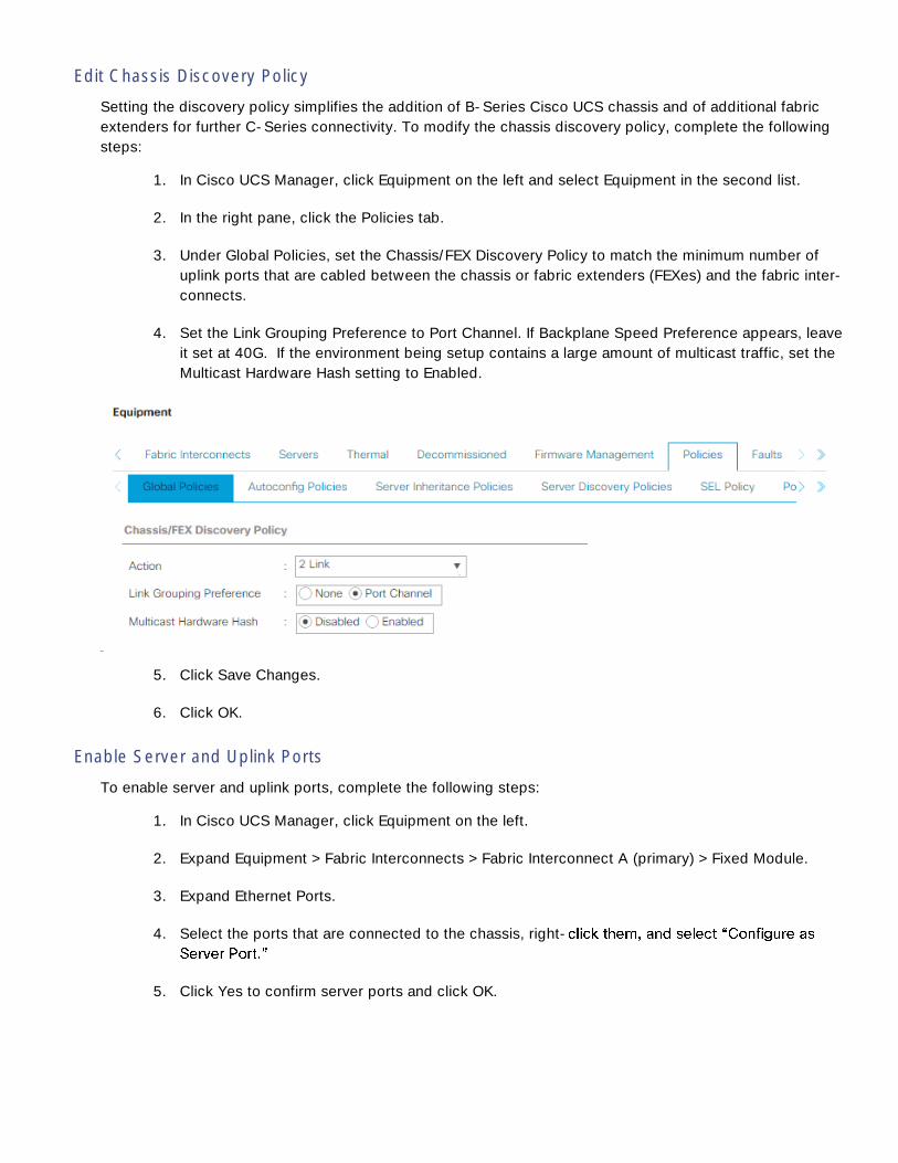
Edit Chassis Discovery Policy
Setting the discovery policy simplifies the addition of B-Series Cisco UCS chassis and of additional fabric
extenders for further C-Series connectivity. To modify the chassis discovery policy, complete the following
steps:
1. In Cisco UCS Manager, click Equipment on the left and select Equipment in the second list.
2. In the right pane, click the Policies tab.
3. Under Global Policies, set the Chassis/FEX Discovery Policy to match the minimum number of
uplink ports that are cabled between the chassis or fabric extenders (FEXes) and the fabric inter-
connects.
4. Set the Link Grouping Preference to Port Channel. If Backplane Speed Preference appears, leave
it set at 40G. If the environment being setup contains a large amount of multicast traffic, set the
Multicast Hardware Hash setting to Enabled.
5. Click Save Changes.
6. Click OK.
Enable Server and Uplink Ports
To enable server and uplink ports, complete the following steps:
1. In Cisco UCS Manager, click Equipment on the left.
2. Expand Equipment > Fabric Interconnects > Fabric Interconnect A (primary) > Fixed Module.
3. Expand Ethernet Ports.
4. Select the ports that are connected to the chassis, right-
5. Click Yes to confirm server ports and click OK.

6. Verify that the ports connected to the chassis are now configured as server ports and are in the
Up state.
7. Select the ports that are connected to the Cisco Nexus switches, right-click them, and select
Configure as Uplink Port.
8. Click Yes to confirm uplink ports and click OK.
9. Expand FC Ports under Fabric Interconnect A.
10. Select the ports that are connected to the NetApp storage controllers, right-click them, and se-
lect Configure as FC Storage Port.
11. Click Yes to confirm FC Storage ports and click OK.
12. Select any unused FC ports, right-click and select Disable. Select Yes and OK.
13. Select Equipment > Fabric Interconnects > Fabric Interconnect B (subordinate) > Fixed Module.
14. Expand Ethernet Ports.
15. Select the ports that are connected to the chassis, right-click them, and select Configure as
Server Port.
16. Click Yes to confirm server ports and click OK.
17. Verify that the ports connected to the chassis are now configured as server ports and are in the
Up state.
18. Select the ports that are connected to the Cisco Nexus switches, right-click them, and select
Configure as Uplink Port.
19. Click Yes to confirm the uplink ports and click OK.
20. Expand FC Ports under Fabric Interconnect A.
21. Select the ports that are connected to the NetApp storage controllers, right-click them, and se-
lect Configure as FC Storage Port.
22. Click Yes to confirm FC Storage ports and click OK.
23. Select any unused FC ports, right-click and select Disable. Select Yes and OK.
Acknowledge Cisco UCS Chassis
To acknowledge all Cisco UCS chassis, complete the following steps:
1. In Cisco UCS Manager, click Equipment on the left.
2. Expand Chassis and select each chassis that is listed.
3. Right-click each chassis and select Acknowledge Chassis.

4. Click Yes and then click OK to complete acknowledging the chassis.
Create Uplink Port Channels to Cisco Nexus Switches
To configure the necessary port channels out of the Cisco UCS environment, complete the following steps:
1. In Cisco UCS Manager, click LAN on the left.
In this procedure, two port channels are created: one from fabric A to both Cisco Nexus switches
and one from fabric B to both Cisco Nexus switches.
2. Under LAN > LAN Cloud, expand the Fabric A tree.
3. Right-click Port Channels.
4. Select Create Port Channel.
5. Enter a unique ID number for the port channel.
6. Enter vPC-Nexus as the name of the port channel.
7. Click Next.
8. Select the ports connected to the Nexus switches to be added to the port channel:
9. Click >> to add the ports to the port channel.
10. Click Finish to create the port channel.

11. Click OK.
12. In the navigation pane, under LAN > LAN Cloud, expand the fabric B tree.
13. Right-click Port Channels.
14. Select Create Port Channel.
15. Enter aunique ID fot the port channel.
16. Enter vPC-Nexus as the name of the port channel.
17. Click Next.
18. Select the ports connected to the Nexus switches to be added to the port channel:
19. Click >> to add the ports to the port channel.
20. Click Finish to create the port channel.
21. Click OK.
Create a WWNN Pool for FC Boot
To configure the necessary WWNN pool for the Cisco UCS environment, complete the following steps on
Cisco UCS Manager.
1. Select SAN on the left.
2. Select Pools > root.
3. Right-click WWNN Pools under the root organization.
4. Select Create WWNN Pool to create the WWNN pool.
5. Enter WWNN-Pool for the name of the WWNN pool.
6. Optional: Enter a description for the WWNN pool.
7. Select Sequential for Assignment Order.

8. Click Next.
9. Click Add.
10. Modify the From field as necessary for the UCS Environment.
Modifications of the WWNN block, as well as the WWPN and MAC Addresses, can convey identi-
fying information for the UCS domain. Within the From field in our example, the 6th octet was
changed from 00 to 48 to represent as identifying information for this being in the UCS 6248 in the
4th cabinet.
Also, when having multiple UCS domains sitting in adjacency, it is important that these blocks, the
WWNN, WWPN, and MAC hold differing values between each set.
11. Specify a size of the WWNN block sufficient to support the available server resources.

12. Click OK.
13. Click Finish and OK to complete creating the WWNN pool.
Create WWPN Pools
To configure the necessary WWPN pools for the Cisco UCS environment, complete the following steps:
1. In Cisco UCS Manager, click SAN on the left.
2. Select Pools > root.
3. In this procedure, two WWPN pools are created, one for each switching fabric.
4. Right-click WWPN Pools under the root organization.
5. Select Create WWPN Pool to create the WWPN pool.
6. Enter WWPN-Pool-A as the name of the WWPN pool.
7. Optional: Enter a description for the WWPN pool.
8. Select Sequential for Assignment Order.

9. Click Next.
10. Click Add.
11. Specify a starting WWPN.
For the FlexPod solution, the recommendation is to place 0A in the next-to-last octet of the start-
ing WWPN to identify all of the WWPNs as fabric A addresses. Merging this with the pattern we
used for the WWNN we see a WWPN block starting with 20:00:00:25:B5:48:0A:00.
12. Specify a size for the WWPN pool that is sufficient to support the available blade or server re-
sources.
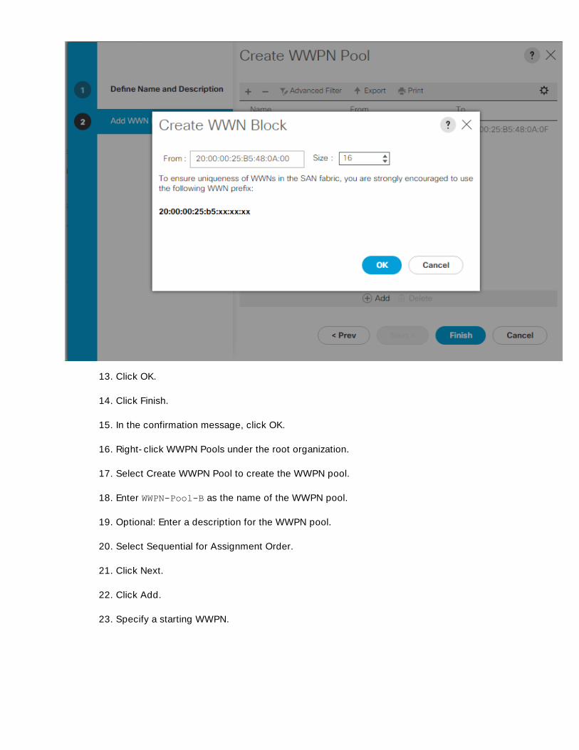
13. Click OK.
14. Click Finish.
15. In the confirmation message, click OK.
16. Right-click WWPN Pools under the root organization.
17. Select Create WWPN Pool to create the WWPN pool.
18. Enter WWPN-Pool-B as the name of the WWPN pool.
19. Optional: Enter a description for the WWPN pool.
20. Select Sequential for Assignment Order.
21. Click Next.
22. Click Add.
23. Specify a starting WWPN.

For the FlexPod solution, the recommendation is to place 0B in the next-to-last octet of the start-
ing WWPN to identify all of the WWPNs as fabric A addresses. Merging this with the pattern we
used for the WWNN we see a WWPN block starting with 20:00:00:25:B5:48:0B:00.
24. Specify a size for the WWPN address pool that is sufficient to support the available blade or
server resources.
25. Click OK.
26. Click Finish.
27. In the confirmation message, click OK.
Create Storage VSANs
To configure the necessary virtual storage area networks (VSANs) for the Cisco UCS environment, complete
the following steps:
1. In Cisco UCS Manager, click the SAN on the left.
In this procedure, two VSANs are created.
2. Select SAN > Storage Cloud.
3. Right-click VSANs.
4. Select Create Storage VSAN.
5. Enter VSAN-A as the name of the VSAN to be used for Fabric A
6. Set FC Zoning to Enabled.
7. Select Fabric A.
8. Enter a unique VSAN ID and a corresponding FCoE VLAN ID for Fabric A. It is recommended to
use the same ID for both parameters and to use something other than 1.

9. Click OK, and then click OK again.
10. Under Storage Cloud, right-click VSANs.
11. Select Create Storage VSAN.
12. Enter VSAN-B as the name of the VSAN to be used for Fabric B.
13. Set FC Zoning to Enabled.
14. Select Fabric B.
15. Enter a unique VSAN ID and a corresponding FCoE VLAN ID for Fabric B. It is recommended use
the same ID for both parameters and to use something other than 1.
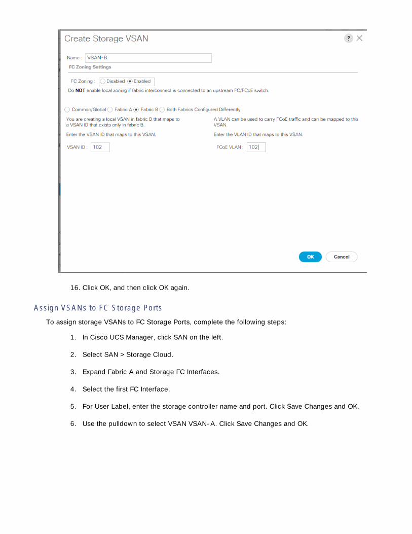
16. Click OK, and then click OK again.
Assign VSANs to FC Storage Ports
To assign storage VSANs to FC Storage Ports, complete the following steps:
1. In Cisco UCS Manager, click SAN on the left.
2. Select SAN > Storage Cloud.
3. Expand Fabric A and Storage FC Interfaces.
4. Select the first FC Interface.
5. For User Label, enter the storage controller name and port. Click Save Changes and OK.
6. Use the pulldown to select VSAN VSAN-A. Click Save Changes and OK.
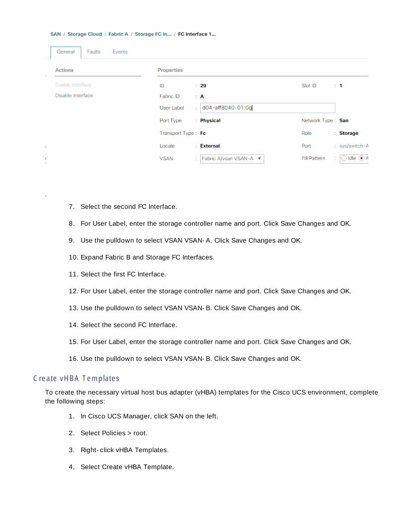
7. Select the second FC Interface.
8. For User Label, enter the storage controller name and port. Click Save Changes and OK.
9. Use the pulldown to select VSAN VSAN-A. Click Save Changes and OK.
10. Expand Fabric B and Storage FC Interfaces.
11. Select the first FC Interface.
12. For User Label, enter the storage controller name and port. Click Save Changes and OK.
13. Use the pulldown to select VSAN VSAN-B. Click Save Changes and OK.
14. Select the second FC Interface.
15. For User Label, enter the storage controller name and port. Click Save Changes and OK.
16. Use the pulldown to select VSAN VSAN-B. Click Save Changes and OK.
Create vHBA Templates
To create the necessary virtual host bus adapter (vHBA) templates for the Cisco UCS environment, complete
the following steps:
1. In Cisco UCS Manager, click SAN on the left.
2. Select Policies > root.
3. Right-click vHBA Templates.
4. Select Create vHBA Template.
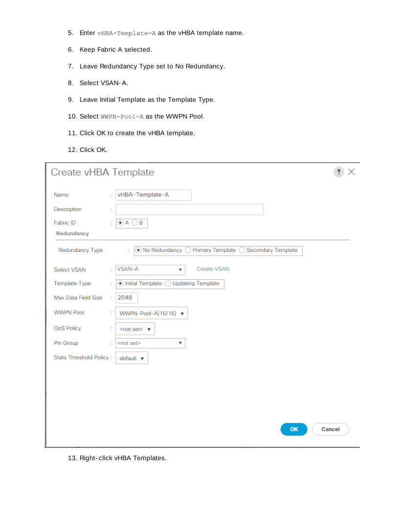
5. Enter vHBA-Template-A as the vHBA template name.
6. Keep Fabric A selected.
7. Leave Redundancy Type set to No Redundancy.
8. Select VSAN-A.
9. Leave Initial Template as the Template Type.
10. Select WWPN-Pool-A as the WWPN Pool.
11. Click OK to create the vHBA template.
12. Click OK.
13. Right-click vHBA Templates.

14. Select Create vHBA Template.
15. Enter vHBA-Template-B as the vHBA template name.
16. Leave Redundancy Type set to No Redundancy.
17. Select Fabric B as the Fabric ID.
18. Select VSAN-B.
19. Leave Initial Template as the Template Type.
20. Select WWPN-Pool-B as the WWPN Pool.
21. Click OK to create the vHBA template.
22. Click OK.
Create SAN Connectivity Policy
To configure the necessary Infrastructure SAN Connectivity Policy, complete the following steps:
1. In Cisco UCS Manager, click SAN on the left.
2. Select SAN > Policies > root.
3. Right-click SAN Connectivity Policies.
4. Select Create SAN Connectivity Policy.
5. Enter Cntr-FC-Boot as the name of the policy.
6. Select the previously created WWNN-Pool for the WWNN Assignment.
7. Click the Add button at the bottom to add a vHBA.
8. In the Create vHBA dialog box, enter Fabric-A as the name of the vHBA.
9. Select the Use vHBA Template checkbox.
10. In the vHBA Template list, select vHBA-Template-A.
11. In the Adapter Policy list, select Linux.

12. Click OK.
13. Click the Add button at the bottom to add a second vHBA.
14. In the Create vHBA dialog box, enter Fabric-B as the name of the vHBA.
15. Select the Use vHBA Template checkbox.
16. In the vHBA Template list, select vHBA-Template-B.
17. In the Adapter Policy list, select Linux
18. Click OK.

19. Click OK to create the SAN Connectivity Policy.
20. Click OK to confirm creation.
Create MAC Address Pools
To configure the necessary MAC address pools for the Cisco UCS environment, complete the following
steps:
1. In Cisco UCS Manager, click LAN on the left.
2. Select Pools > root.
In this procedure, two MAC address pools are created, one for each switching fabric.
3. Right-click MAC Pools under the root organization.
4. Select Create MAC Pool to create the MAC address pool.
5. Enter MAC-Pool-A as the name of the MAC pool.
6. Optional: Enter a description for the MAC pool.
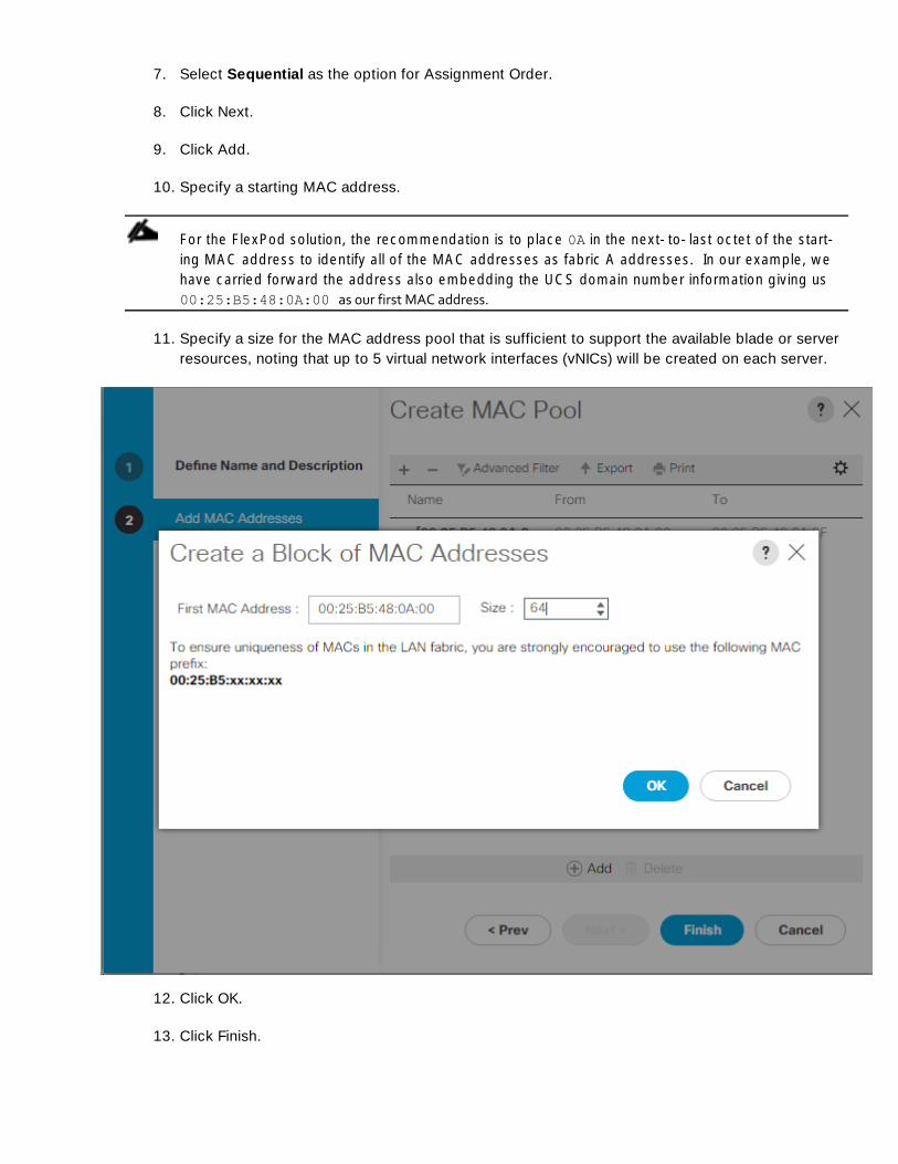
7. Select Sequential as the option for Assignment Order.
8. Click Next.
9. Click Add.
10. Specify a starting MAC address.
For the FlexPod solution, the recommendation is to place 0A in the next-to-last octet of the start-
ing MAC address to identify all of the MAC addresses as fabric A addresses. In our example, we
have carried forward the address also embedding the UCS domain number information giving us
00:25:B5:48:0A:00 as our first MAC address.
11. Specify a size for the MAC address pool that is sufficient to support the available blade or server
resources, noting that up to 5 virtual network interfaces (vNICs) will be created on each server.
12. Click OK.
13. Click Finish.

14. In the confirmation message, click OK.
15. Right-click MAC Pools under the root organization.
16. Select Create MAC Pool to create the MAC address pool.
17. Enter MAC-Pool-B as the name of the MAC pool.
18. Optional: Enter a description for the MAC pool.
19. Select Sequential as the option for Assignment Order.
20. Click Next.
21. Click Add.
22. Specify a starting MAC address.
For the FlexPod solution, it is recommended to place 0B in the next to last octet of the starting
MAC address to identify all the MAC addresses in this pool as fabric B addresses. Once again, we
have carried forward in our example of also embedding the UCS domain number information giving
us 00:25:B5:48:0B:00 as our first MAC address.
23. Specify a size for the MAC address pool that is sufficient to support the available blade or server
resources.
24. Click OK.
25. Click Finish.
26. In the confirmation message, click OK.
Create UUID Suffix Pool
To configure the necessary universally unique identifier (UUID) suffix pool for the Cisco UCS environment,
complete the following steps:
1. In Cisco UCS Manager, click Servers on the left.
2. Select Pools > root.
3. Right-click UUID Suffix Pools.
4. Select Create UUID Suffix Pool.
5. Enter UUID-Pool as the name of the UUID suffix pool.
6. Optional: Enter a description for the UUID suffix pool.
7. Keep the prefix at the derived option.

8. Select Sequential for the Assignment Order.
9. Click Next.
10. Click Add to add a block of UUIDs.
11. Keep the From field at the default setting.
12. Specify a size for the UUID block that is sufficient to support the available blade or server re-
sources.
13. Click OK.
14. Click Finish.
15. Click OK.
Create Server Pool
To configure the necessary server pool for the Cisco UCS environment, complete the following steps:
Consider creating unique server pools to achieve the granularity that is required in your environ-
ment.
1. In Cisco UCS Manager, click Servers on the left.
2. Select Pools > root.
3. Right-click Server Pools.
4. Select Create Server Pool.
5. Enter Container-Pool as the name of the server pool.
6. Optional: Enter a description for the server pool.
7. Click Next.
8. Select ten (or more) servers to be used for this solution and click >> to add them to the Con-
tainer-Pool server pool.
9. Click Finish.
10. Click OK.
Create VLANs
To configure the necessary virtual local area networks (VLANs) for the Cisco UCS environment, complete the
following steps:
1. In Cisco UCS Manager, click LAN on the left.

In this procedure, four unique VLANs are created.
2. Select LAN > LAN Cloud.
3. Right-click VLANs.
4. Select Create VLANs.
5. Enter Native-VLAN as the name of the VLAN to be used as the native VLAN.
6. Keep the Common/Global option selected for the scope of the VLAN.
7. Enter the native VLAN ID.
8. Keep the Sharing Type as None.
9. Click OK, and then click OK again.
10. Expand the list of VLANs in the navigation pane, right-click the newly created Native-VLAN and
select Set as Native VLAN.
11. Click Yes, and then click OK.
12. Right-click VLANs.
13. Select Create VLANs
14. Enter Container-MGMT-VLAN as the name of the VLAN to be used for management traffic.
15. Keep the Common/Global option selected for the scope of the VLAN.
16. Enter the Container management VLAN ID.
17. Keep the Sharing Type as None.
18. Click OK, and then click OK again.
19. Right-click VLANs.
20. Select Create VLANs.
21. Enter Container-MGMT-NFS as the name of the VLAN to be used for NFS.
22. Keep the Common/Global option selected for the scope of the VLAN.
23. Enter the Container MGMT NFS VLAN ID.
24. Keep the Sharing Type as None.
25. Click OK, and then click OK again.
26. Select Create VLANs.
27. Enter Container-TNT-A-NFS as the name of the VLAN to be used for NFS.
28. Keep the Common/Global option selected for the scope of the VLAN.
29. Enter the Container Tenant A NFS VLAN ID.
30. Keep the Sharing Type as None.
31. Click OK, and then click OK again.
Modify Default Host Firmware Package
Firmware management policies allow the administrator to select the corresponding packages for a given
server configuration. These policies often include packages for adapter, BIOS, board controller, FC adapters,
host bus adapter (HBA) option ROM, and storage controller properties.
To create a firmware management policy for a given server configuration in the Cisco UCS environment,
complete the following steps:
1. In Cisco UCS Manager, click Servers on the left.
2. Select Policies > root.

3. Expand Host Firmware Packages.
4. Select default.
5. In the Actions pane, select Modify Package Versions.
6. Select the version 3.1(2e) for both the Blade and Rack Packages.
7. Click OK then OK again to modify the host firmware package.
Set Jumbo Frames in Cisco UCS Fabric
To configure jumbo frames and enable quality of service in the Cisco UCS fabric, complete the following
steps:

1. In Cisco UCS Manager, click LAN on the left.
2. Select LAN > LAN Cloud > QoS System Class.
3. In the right pane, click the General tab.
4. On the Best Effort row, enter 9216 in the box under the MTU column.
5. Click Save Changes in the bottom of the window.
6. Click OK
Create Local Disk Configuration Policy (Optional)
A local disk configuration for the Cisco UCS environment is necessary if the servers in the environment do
not have a local disk.
This policy should not be used on servers that contain local disks.
To create a local disk configuration policy, complete the following steps:
1. In Cisco UCS Manager, click Servers on the left.
2. Select Policies > root.
3. Right-click Local Disk Config Policies.
4. Select Create Local Disk Configuration Policy.
5. Enter SAN-Boot as the local disk configuration policy name.
6. Change the mode to No Local Storage.
7. Click OK to create the local disk configuration policy.

8. Click OK.
Create Network Control Policy for Cisco Discovery Protocol (CDP) and Link Layer Discovery
Protocol (LLDP)
To create a network control policy that enables CDP and LLDP on virtual network ports, complete the
following steps:
1. In Cisco UCS Manager, click LAN on the left.
2. Select Policies > root.
3. Right-click Network Control Policies.
4. Select Create Network Control Policy.

5. Enter Enable-CDP-LLDP as the policy name.
6. For CDP, select the Enabled option.
7. For LLDP, scroll down and select Enabled for both Transmit and Receive.
8. Click OK to create the network control policy.
9. Click OK.
Create Power Control Policy
To create a power control policy for the Cisco UCS environment, complete the following steps:
1. In Cisco UCS Manager, click Servers tab on the left.
2. Select Policies > root.
3. Right-click Power Control Policies.
4. Select Create Power Control Policy.
5. Enter No-Power-Cap as the power control policy name.
6. Change the power capping setting to No Cap.
7. Click OK to create the power control policy.
8. Click OK.
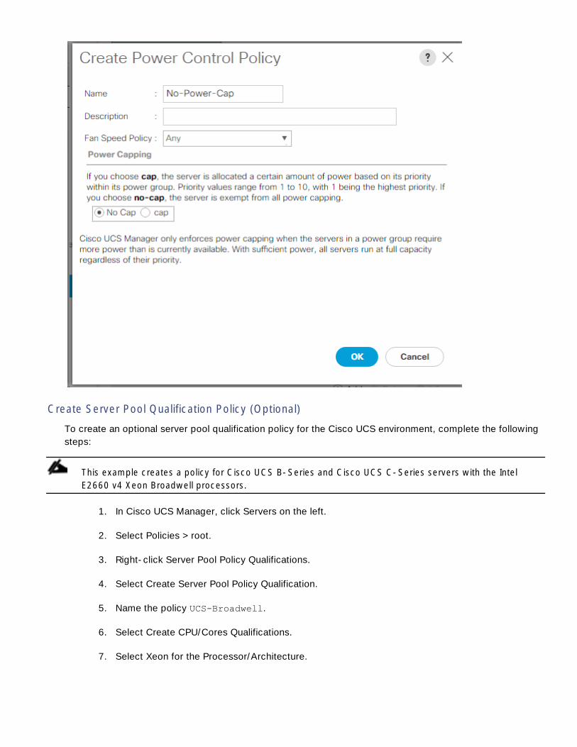
Create Server Pool Qualification Policy (Optional)
To create an optional server pool qualification policy for the Cisco UCS environment, complete the following
steps:
This example creates a policy for Cisco UCS B-Series and Cisco UCS C-Series servers with the Intel
E2660 v4 Xeon Broadwell processors.
1. In Cisco UCS Manager, click Servers on the left.
2. Select Policies > root.
3. Right-click Server Pool Policy Qualifications.
4. Select Create Server Pool Policy Qualification.
5. Name the policy UCS-Broadwell.
6. Select Create CPU/Cores Qualifications.
7. Select Xeon for the Processor/Architecture.

8. Enter UCS-CPU-E52660E as the PID.
9. Click OK to create the CPU/Core qualification.
10. Click OK to create the policy then OK for the confirmation.
Create Server BIOS Policy
To create a server BIOS policy for the Cisco UCS environment, complete the following steps:
1. In Cisco UCS Manager, click Servers on the left.
2. Select Policies > root.
3. Right-click BIOS Policies.
4. Select Create BIOS Policy.
5. Enter Cntr-Host as the BIOS policy name.
6. Change the Quiet Boot setting to disabled.

7. Change Consistent Device Naming to enabled.
8. Click on the Processor tab on the left pane.
9. Set the following within the Processor tab.
10. Processor C state disabled
11. Processor C1E disabled
12. Processor C3 Report disabled
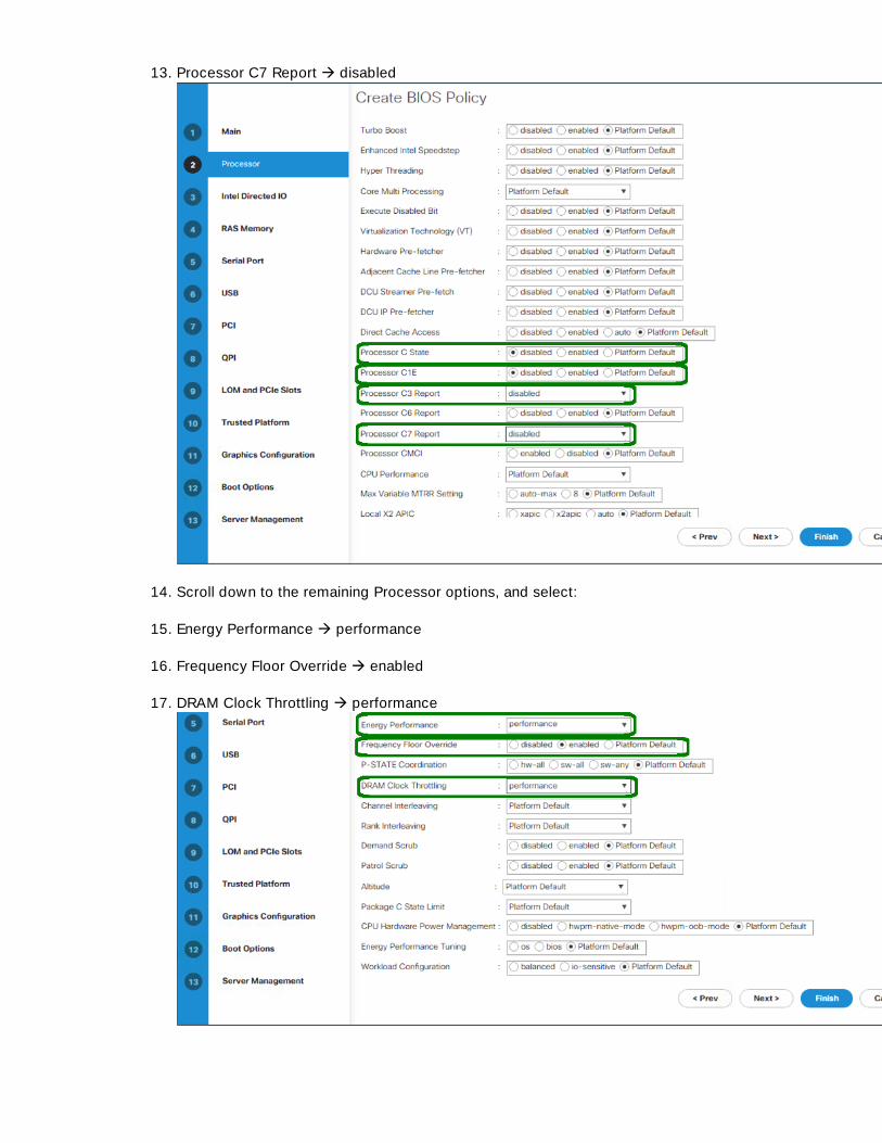
13. Processor C7 Report disabled
14. Scroll down to the remaining Processor options, and select:
15. Energy Performance performance
16. Frequency Floor Override enabled
17. DRAM Clock Throttling performance

18. Click on the RAS memory option, and select:
19. LV DDR Mode performance-mode
20. Click Finish to create the BIOS policy
21. Click OK.
Update the Default Maintenance Policy
To update the default Maintenance Policy, complete the following steps:
1. In Cisco UCS Manager, click Servers on the left.
2. Select Policies > root.
3. Select Maintenance Policies > default.
4. Change the Reboot Policy to User Ack.
5.

6. Click Save Changes.
7. Click OK to accept the change.
Create vNIC Templates
To create multiple virtual network interface card (vNIC) templates for the Cisco UCS environment, complete
the following steps. A total of 3 vNIC Templates will be created.
Create Container Management vNIC
1. In Cisco UCS Manager, click LAN on the left.
2. Select Policies > root.
3. Right-click vNIC Templates.
4. Select Create vNIC Template.
5. Enter Cntr-Template as the vNIC template name.
6. Keep Fabric A selected.
7. Select the Enable Failover checkbox.
8. Leave Redundancy Type set at No Redundancy.
9. Under Target, make sure that only the Adapter checkbox is selected.
10. Select Updating Template as the Template Type.
11. Under VLANs, select the checkbox for Container-MGMT-VLAN.
12. Set Container-MGMT-VLAN as the native VLAN.
13. Select vNIC Name for the CDN Source.

14. For MTU, enter 1500.
15. In the MAC Pool list, select MAC-Pool-A.
16. In the Network Control Policy list, select Enable-CDP-LLDP.
17. Click OK to create the vNIC template.
18. Click OK.
Create NFS vNICs
1. In Cisco UCS Manager, click LAN on the left.
2. Select Policies > root.

3. Right-click vNIC Templates.
4. Select Create vNIC Template.
5. Enter Container-NFS-A as the vNIC template name.
6. Keep Fabric A selected.
7. Do not select the Enable Failover checkbox.
8. Select Primary Template for Redundancy Type.
9. Leave the Peer Redundancy Template set to <not set>.
10. Under Target, make sure that only the Adapter checkbox is selected.
11. Select Updating Template as the Template Type.
12. Under VLANs, select the checkboxes for the Container-MGMT-NFS and Container-TNT-A-NFS
VLANs.
13. Set the Container-MGMT-NFS VLAN as the Native VLAN.
14. Select vNIC Name for the CDN Source.
15. For MTU, enter 9000.
16. In the MAC Pool list, select MAC-Pool-A.
17. In the Network Control Policy list, select Enable-CDP-LLDP.

18. Click OK to create the vNIC template.
19. Click OK.
Repeat these equivalent steps for template Container-NFS-B:
1. Select LAN on the left.
2. Select Policies > root.
3. Right-click vNIC Templates.
4. Select Create vNIC Template

5. Enter Container-NFS-B as the vNIC template name.
6. Select Fabric B.
7. Do not select the Enable Failover checkbox.
8. Set Redundancy Type to Secondary Template.
9. Select Container-NFA-A for the Peer Redundancy Template.
10. In the MAC Pool list, select MAC-Pool-B. The MAC Pool is all that needs to be selected for the
Secondary Template.
11. Click OK to create the vNIC template.
12. Click OK.
Create LAN Connectivity Policy
To configure the necessary Container LAN Connectivity Policy, complete the following steps:
1. In Cisco UCS Manager, click LAN on the left.
2. Select LAN > Policies > root.
3. Right-click LAN Connectivity Policies.
4. Select Create LAN Connectivity Policy.
5. Enter Cntr-FC-Boot as the name of the policy.
6. Click the upper Add button to add a vNIC.
7. In the Create vNIC dialog box, enter eno1 as the name of the vNIC.
8. Select the Use vNIC Template checkbox.
9. In the vNIC Template list, select Cntr-Template.
10. In the Adapter Policy list, select Linux.
11. Click OK to add this vNIC to the policy.
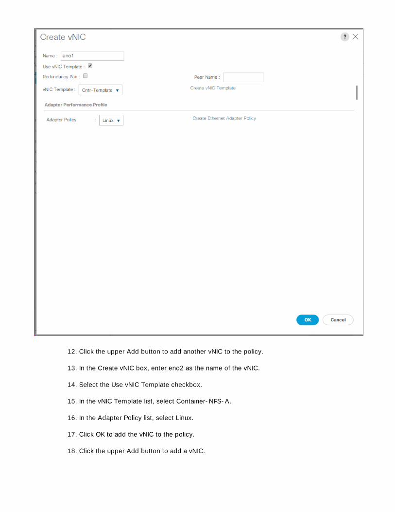
12. Click the upper Add button to add another vNIC to the policy.
13. In the Create vNIC box, enter eno2 as the name of the vNIC.
14. Select the Use vNIC Template checkbox.
15. In the vNIC Template list, select Container-NFS-A.
16. In the Adapter Policy list, select Linux.
17. Click OK to add the vNIC to the policy.
18. Click the upper Add button to add a vNIC.
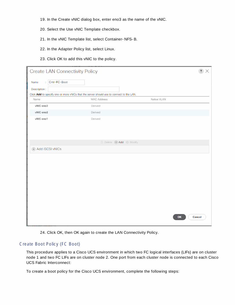
19. In the Create vNIC dialog box, enter eno3 as the name of the vNIC.
20. Select the Use vNIC Template checkbox.
21. In the vNIC Template list, select Container-NFS-B.
22. In the Adapter Policy list, select Linux.
23. Click OK to add this vNIC to the policy.
24. Click OK, then OK again to create the LAN Connectivity Policy.
Create Boot Policy (FC Boot)
This procedure applies to a Cisco UCS environment in which two FC logical interfaces (LIFs) are on cluster
node 1 and two FC LIFs are on cluster node 2. One port from each cluster node is connected to each Cisco
UCS Fabric Interconnect:
To create a boot policy for the Cisco UCS environment, complete the following steps:

1. In Cisco UCS Manager, click Servers on the left.
2. Select Policies > root.
3. Right-click Boot Policies.
4. Select Create Boot Policy.
5. Enter Boot-FC-Cntr as the name of the boot policy.
6. Optional: Enter a description for the boot policy.
Do not select the Reboot on Boot Order Change checkbox.
7. Keep the Reboot on Boot Order Change option cleared.
8. Expand the Local Devices drop-down menu and select Add Remote CD/DVD.
9. Expand the vHBAs drop-down menu and select Add SAN Boot.
10. Select the Primary Type.
11. Enter Fabric-A in the vHBA field.
12. Confirm that Primary is selected for the Type option.
13. Click OK to add the SAN boot initiator.
14. From the vHBA expanded menu, select Add SAN Boot Target.
15. Keep 0 as the value for Boot Target LUN.

16. Enter the WWPN for fcp_lif01a from the Container-SVM on the storage cluster.
To obtain this information, log in to the storage cluster and run the network interface show –
vserver Container-SVM command.
17. Select Primary for the SAN boot target type.
18. Click OK to add the SAN boot target.
19. From the vHBA drop-down menu, select Add SAN Boot Target.
20. Enter 0 as the value for Boot Target LUN.
21. Enter the WWPN for fcp_lif02a from the Container-SVM on the storage cluster.
22. Click OK to add the SAN boot target.
23. From the vHBA expanded menu, select Add SAN Boot.
24. In the Add SAN Boot dialog box, enter Fabric-B in the vHBA box.
25. The SAN boot type should automatically be set to Secondary.
26. Click OK to add the SAN boot initiator.
27. From the vHBA drop-down menu, select Add SAN Boot Target.
28. Keep 0 as the value for Boot Target LUN.
29. Enter the WWPN for fcp_lif01b from the Container-SVM on the storage cluster.

30. Select Primary for the SAN boot target type.
31. Click OK to add the SAN boot target.
32. From the vHBA drop-down menu, select Add SAN Boot Target.
33. Keep 0 as the value for Boot Target LUN.
34. Enter the WWPN for fcp_lif02b from the Container-SVM on the storage cluster.
35. Click OK to add the SAN boot target.
36. Click OK, then click OK again to create the boot policy.
Create Service Profile Template (FC Boot)
In this procedure, one service profile template for Docker Container hosts is created for Fabric A boot.
To create the service profile template, complete the following steps:
1. In Cisco UCS Manager, click Servers on the left.
2. Select Service Profile Templates > root.

3. Right-click root.
4. Select Create Service Profile Template to open the Create Service Profile Template wizard.
5. Enter Docker-Host-FC-A as the name of the service profile template. This service profile tem-
plate is configured to boot from storage node 1 on fabric A.
6.
7. Under UUID, select UUID_Pool as the UUID pool.
8. Click Next.
Configure Storage Provisioning
1. If you have servers with no physical disks, click on the Local Disk Configuration Policy and select
the SAN-Boot Local Storage Policy. Otherwise, select the default Local Storage Policy.
2. Click Next.
Configure Networking Options
1. Keep the default setting for Dynamic vNIC Connection Policy.
2.

3. Select Cntr-FC-Boot from the LAN Connectivity Policy pull-down.
4. Leave Initiator Name Assignment at <not set>.
5. Click Next.
Configure SAN Connectivity
1. c-
2. Pick the Cntr-FC-Boot option from the SAN Connectivity Policy pull-down.
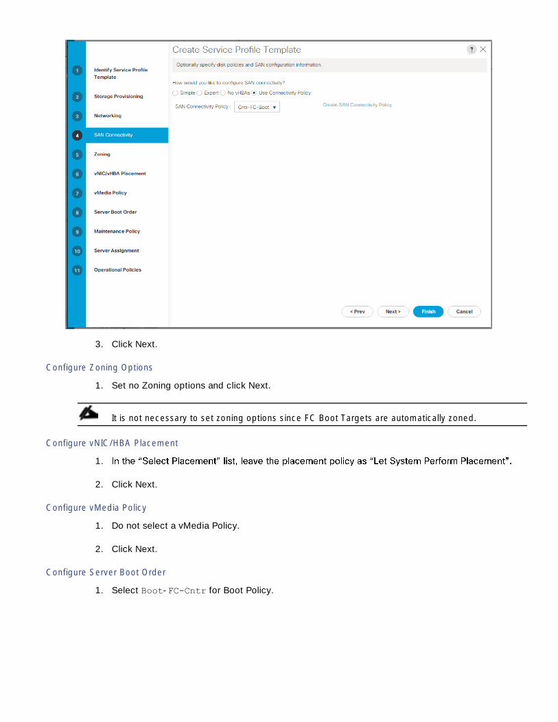
3. Click Next.
Configure Zoning Options
1. Set no Zoning options and click Next.
It is not necessary to set zoning options since FC Boot Targets are automatically zoned.
Configure vNIC/HBA Placement
1.
2. Click Next.
Configure vMedia Policy
1. Do not select a vMedia Policy.
2. Click Next.
Configure Server Boot Order
1. Select Boot-FC-Cntr for Boot Policy.

2. Click Next to continue to the next section.
Configure Maintenance Policy
1. Change the Maintenance Policy to default.
2. Click Next.
Configure Server Assignment
To configure server assignment, complete the following steps:
1. In the Pool Assignment list, select Container-Pool.
2. Select Down as the power state to be applied when the profile is associated with the server.
3. -
4. Expand Firmware Management at the bottom of the page and select the default policy

5. Click Next.
Configure Operational Policies
To configure the operational policies, complete the following steps:
1. In the BIOS Policy list, select Cntr-Host.
2. Expand Power Control Policy Configuration and select No-Power-Cap in the Power Control Policy
list.
3. Click Finish to create the service profile template.
4. Click OK in the confirmation message.
Create Service Profiles
To create service profiles from the service profile template, complete the following steps:
1. Connect to UCS Manager, click Servers on the left.
2. Select Service Profile Templates > root > Service Template Docker-Host-FC-A.
3. Right-click Docker-Host-FC-A-and select Create Service Profiles from Template.
4. Enter Docker-Host-0 as the service profile prefix.
5.
6. Enter 9
7. Click OK to create the service profiles.

8. Click OK in the confirmation message.
9. Right-click Docker-Host-FC-A-and select Create Service Profiles from Template.
10. Enter Docker-Host- as the service profile prefix.
11. Enter 10
12. Enter 1
13. Click OK to create the service profiles.
14. Click OK in the confirmation message.
15. m-
ple, UCP-Ctrl-1.
Gather Necessary Information
After the Cisco UCS service profiles have been created, each infrastructure server in the environment will
have a unique configuration. To proceed with the FlexPod deployment, specific information must be
gathered from each Cisco UCS server and from the NetApp controllers. Insert the required information into
Table 18 and Table 19.
Table 18. WWPNs from NetApp Storage
SVM Target LIF WWPN (FC)
Container-SVM fcp_lif01a

SVM Target LIF WWPN (FC)
fcp_lif01b
fcp_lif02a
fcp_lif02b
To obtain the FC WWPNs, run the network interface show command on the storage cluster management
interface.
Table 19. FC WWPNs for fabric A and fabric B
Cisco UCS Service Profile Name Initiator: WWPNs (FC) Variables
Docker-Host-01 <docker-host-01-wwpna>
<docker-host-01-wwpnb>
Docker-Host- 02 <docker-host-02-wwpna>
<docker-host-02-wwpnb>
Docker-Host-03 <docker-host-03-wwpna>
<docker-host-03-wwpnb>
Docker-Host-04 <docker-host-04-wwpna>
<docker-host-04-wwpnb>
Docker-Host-05 <docker-host-05-wwpna>
<docker-host-05-wwpnb>
Docker-Host-06 <docker-host-06-wwpna>
<docker-host-06-wwpnb>
Docker-Host-07 <docker-host-07-wwpna>
<docker-host-07-wwpnb>
Docker-Host-08 <docker-host-08-wwpna>
<docker-host-08-wwpnb>
Docker-Host-09 <docker-host-09-wwpna>
<docker-host-09-wwpnb>

Cisco UCS Service Profile Name Initiator: WWPNs (FC) Variables
Docker-Host-10 <docker-host-10-wwpna>
<docker-host-10-wwpnb>
To obtain the information on FC vHBA WWPN in Cisco UCS Manager GUI, go to Servers > Service Profiles
> root. Click each service profile and
WWPNs are displayed in the table at the bottom of the page.
Data ONTAP SAN Storage Setup
Create Igroups
Create igroups by entering the following commands from the cluster management node SSH connection:
igroup create –vserver Container-SVM –igroup Docker-Host-01 –protocol fcp –ostype linux –initiator <docker-
host-01-wwpna>, <docker-host-01-wwpnb>
igroup create –vserver Container-SVM –igroup Docker-Host-02 –protocol fcp –ostype linux –initiator <docker-
host-02-wwpna>, <docker-host-02-wwpnb>
igroup create –vserver Container-SVM –igroup Docker-Host-03 –protocol fcp –ostype linux –initiator <docker-
host-03-wwpna>, <docker-host-03-wwpnb>
igroup create –vserver Container-SVM –igroup Docker-Host-04 –protocol fcp –ostype linux –initiator <docker-
host-04-wwpna>, <docker-host-04-wwpnb>
igroup create –vserver Container-SVM –igroup Docker-Host-05 –protocol fcp –ostype linux –initiator <docker-
host-05-wwpna>, <docker-host-05-wwpnb>
igroup create –vserver Container-SVM –igroup Docker-Host-06 –protocol fcp –ostype linux –initiator <docker-
host-06-wwpna>, <docker-host-06-wwpnb>
igroup create –vserver Container-SVM –igroup Docker-Host-07 –protocol fcp –ostype linux –initiator <docker-
host-07-wwpna>, <docker-host-07-wwpnb>
igroup create –vserver Container-SVM –igroup Docker-Host-08 –protocol fcp –ostype linux –initiator <docker-
host-08-wwpna>, <docker-host-08-wwpnb>
igroup create –vserver Container-SVM –igroup Docker-Host-09 –protocol fcp –ostype linux –initiator <docker-
host-09-wwpna>, <docker-host-09-wwpnb>

igroup create –vserver Container-SVM –igroup Docker-Host-10 –protocol fcp –ostype linux –initiator <docker-
host-10-wwpna>, <docker-host-10-wwpnb>
Use the values listed in Table12 and Table 13 for the WWPN information.
To view the igroups that were just created, type igroup show.
Map LUNs to igroups
From the storage cluster management SSH connection, enter the following commands:
lun map –vserver Container-SVM –volume Linux_Boot –lun Docker-Host-01 –igroup Docker-Host-01 –lun-id 0
lun map –vserver Container-SVM –volume Docker_Data_LUNs –lun Docker-Host-01 –igroup Docker-Host-01 –lun-id 1
lun map –vserver Container-SVM –volume Linux_Boot –lun Docker-Host-02 –igroup Docker-Host-02 –lun-id 0
lun map –vserver Container-SVM –volume Docker_Data_LUNs –lun Docker-Host-02 –igroup Docker-Host-02 –lun-id 1
lun map –vserver Container-SVM –volume Linux_Boot –lun Docker-Host-03 –igroup Docker-Host-03 –lun-id 0
lun map –vserver Container-SVM –volume Docker_Data_LUNs –lun Docker-Host-03 –igroup Docker-Host-03 –lun-id 1
lun map –vserver Container-SVM –volume Linux_Boot –lun Docker-Host-04 –igroup Docker-Host-04 –lun-id 0
lun map –vserver Container-SVM –volume Docker_Data_LUNs –lun Docker-Host-04 –igroup Docker-Host-04 –lun-id 1
lun map –vserver Container-SVM –volume Linux_Boot –lun Docker-Host-05 –igroup Docker-Host-05 –lun-id 0
lun map –vserver Container-SVM –volume Docker_Data_LUNs –lun Docker-Host-05 –igroup Docker-Host-05 –lun-id 1
lun map –vserver Container-SVM –volume Linux_Boot –lun Docker-Host-06 –igroup Docker-Host-06 –lun-id 0
lun map –vserver Container-SVM –volume Docker_Data_LUNs –lun Docker-Host-06 –igroup Docker-Host-06 –lun-id 1
lun map –vserver Container-SVM –volume Linux_Boot –lun Docker-Host-07 –igroup Docker-Host-07 –lun-id 0
lun map –vserver Container-SVM –volume Docker_Data_LUNs –lun Docker-Host-07 –igroup Docker-Host-07 –lun-id 1
lun map –vserver Container-SVM –volume Linux_Boot –lun Docker-Host-08 –igroup Docker-Host-08 –lun-id 0
lun map –vserver Container-SVM –volume Docker_Data_LUNs –lun Docker-Host-08 –igroup Docker-Host-08 –lun-id 1
lun map –vserver Container-SVM –volume Linux_Boot –lun Docker-Host-09 –igroup Docker-Host-09 –lun-id 0
lun map –vserver Container-SVM –volume Docker_Data_LUNs –lun Docker-Host-09 –igroup Docker-Host-09 –lun-id 1

lun map –vserver Container-SVM –volume Linux_Boot –lun Docker-Host-10 –igroup Docker-Host-10 –lun-id 0
lun map –vserver Container-SVM –volume Docker_Data_LUNs –lun Docker-Host-10 –igroup Docker-Host-10 –lun-id 1
Installation of Red Hat Enterprise Linux Operating System
After the service profile association, Red Hat Enterprise Linux 7.3 Operating System is installed on all the
blade servers. The following section provides detailed procedure for installing Red Hat Linux 7.3 OS on the
Boot-Lun created using UCSM Storage Profile.
Complete the following to install Red Hat Enterprise Linux 7.3 OS.
1. From Cisco UCS Manager, click Servers Service Profiles
2. Select a node (for example, UCP-Ctrl-1) and click KVM Console.
3. In the KVM Console select Virtual Media tab. From the drop-down menu select Activate Virtual
Devices.

4. Once the virtual devices get activated, select Map CD/DVD option.
5. Click Browse to locate the Red Hat Enterprise Linux Server 7.3 installer ISO image file.

6. The image gets mapped to CD/DVD.
7. In the KVM window, select the KVM tab to monitor during boot.
8. In the KVM window, select the Macros > Static Macros > Ctrl-Alt-Del button in the upper left
corner.
9. Click OK.
10. Click OK to reboot the system.
11. Select the option - Install Red Hat Enterprise Linux 7.3.

12. Select Language and Click Continue.

13. Click DATE & TIME.

14. Select Region and City in DATE & TIME screen and Click Done.

15. Click SOFTWARE SELECTION, select the option Server with GUI. Select the necessary add-ons
for the selected environment. Click Done.
16. Select Server with GUI and check box Java Platform, Network File System Client, Compatibility
Libraries, and Development Tools as shown below. Click Done.

17. Click INSTALLATION DESTINATION.

18. Under Specialized & Network Disks, select Add a disk.
19. Click Multipath Devices on INSTALLATION DESTINATION screen. Select 60 GiB LUN as shown.
Click Done.

20. Click Done on device selection for installation destination.

21. Click NETWORK & HOSTNAME. Select the Ethernet interface eno1 and enter the host name (for
example, UCP-Ctrl-1.vikings.cisco.com). Click Configure. Enter an MTU of 1500. Select the IPv4
Settings tab, then the Manual Method. Click Add and enter the IPv4 address, subnet mask, gate-
way, DNS server IP, and the Search domain. Click Save. On the upper right, turn the connection
on.


22. Click Done. And click Begin Installation.
23. While the installation in is progress, click Root Password to assert a password and then click Us-
er Creation to set user credentials. Click Done.

24. Once the installation is complete, upon prompting click Reboot.

After the reboot, verify that interfaces are up and IP addresses are configured by running # cat
/etc/sysconfig/network-scripts/ifcfg-eno1. If not configured, configure it either in RHEL GUI or via CLI in
/etc/sysconfig/network-scripts/ifcfg-eno1
Docker Enterprise Edition Installation
Docker EE is a software subscription that includes 3 products:
Docker EE (Basic)
Docker Trusted Registry
Docker Universal Control Plane
Both Docker UCP and DTR can be installed on-premises or on cloud as part of the installation of Docker EE
on Cisco UCS blades running on a bare metal operating system. Operating system does not need any
additional libraries or software stack. RHEL OS is sufficient to start and all the required software bits get
installed as part of Docker Engine installation.

There are mainly 3 steps to bring up the entire DDC on a cluster of bare metal hosts. We are required to
install OS followed by Docker Enterprise Edition. Support matrix for Docker EE includes RHEL 7.3 release.
We have used the same in this solution.
We have used root login for the entire workflow for Docker EE platform bring-up. This can also be done
Complete Host Networking Setup
1. The network devices and IP network need to be setup on each Docker host. The can be done
from the KVM console or from an ssh session as root, provided that the eno1 network interface
was set up correctly during setup. Each node was equipped with three Cisco UCS virtual net-
work interfaces (vNICs) in the UCS Service profile. The three vNICs are eno1, eno2, and eno3.
Eno1 is connected to the Docker management network and is configured on Fabric A in the UCS
with failover. Eno2 and eno3 are configured on Fabric A and Fabric B respectively and do not
have failover configured. These interfaces are bonded to the bond0 interface. Bond0 uses
adaptive load balancing (ALB) for non-switch aware link aggregation.
2. Log into each Docker host and setup up network configuration files in /etc/sysconfig/network-
scripts for bond0 (the bonded Docker Management NFS interface), bond0.<cntr-tnt-a-nfs-vlan-
the hardware address (MAC) to the eno1, eno2, and eno3 interface files. The MAC address can
-tnt-a-nfs-vlan-
id>, eno2, and eno3 are configured with Jumbo frames (MTU 9000). Sample network files are
shown below:
[root@ucp-ctrl-1 /]# ifconfig -a
eno1: flags=4163<UP,BROADCAST,RUNNING,MULTICAST> mtu 1500
inet 192.168.91.21 netmask 255.255.255.0 broadcast 192.168.91.255
inet6 fe80::1d27:1769:aeb2:7dfb prefixlen 64 scopeid 0x20<link>
ether 00:25:b5:48:0a:0a txqueuelen 1000 (Ethernet)
RX packets 578 bytes 56248 (54.9 KiB)
RX errors 0 dropped 52 overruns 0 frame 0
TX packets 143 bytes 19216 (18.7 KiB)
TX errors 0 dropped 0 overruns 0 carrier 0 collisions 0
eno2: flags=4163<UP,BROADCAST,RUNNING,MULTICAST> mtu 9000
ether 00:25:b5:48:0a:19 txqueuelen 1000 (Ethernet)
RX packets 31 bytes 8369 (8.1 KiB)
RX errors 0 dropped 27 overruns 0 frame 0
TX packets 0 bytes 0 (0.0 B)
TX errors 0 dropped 0 overruns 0 carrier 0 collisions 0
eno3: flags=4163<UP,BROADCAST,RUNNING,MULTICAST> mtu 9000
ether 00:25:b5:48:0b:0f txqueuelen 1000 (Ethernet)
RX packets 31 bytes 8369 (8.1 KiB)
RX errors 0 dropped 27 overruns 0 frame 0
TX packets 0 bytes 0 (0.0 B)
TX errors 0 dropped 0 overruns 0 carrier 0 collisions 0
lo: flags=73<UP,LOOPBACK,RUNNING> mtu 65536
inet 127.0.0.1 netmask 255.0.0.0
inet6 ::1 prefixlen 128 scopeid 0x10<host>
loop txqueuelen 1 (Local Loopback)
RX packets 4 bytes 340 (340.0 B)
RX errors 0 dropped 0 overruns 0 frame 0
TX packets 4 bytes 340 (340.0 B)
TX errors 0 dropped 0 overruns 0 carrier 0 collisions 0
[root@ucp-ctrl-1 /]# cat /etc/sysconfig/network-scripts/ifcfg-eno1

HWADDR="00:25:b5:48:0a:0a"
TYPE="Ethernet"
BOOTPROTO="none"
DEFROUTE="yes"
IPV4_FAILURE_FATAL="no"
IPV6INIT="no"
IPV6_AUTOCONF="yes"
IPV6_DEFROUTE="yes"
IPV6_FAILURE_FATAL="no"
IPV6_ADDR_GEN_MODE="stable-privacy"
NAME="eno1"
DEVICE="eno1"
ONBOOT="yes"
MTU="1500"
IPADDR="192.168.91.21"
PREFIX="24"
GATEWAY="192.168.91.254"
DNS1="10.1.156.9"
DOMAIN="vikings.cisco.com"
IPV6_PEERDNS="yes"
IPV6_PEERROUTES="yes"
IPV6_PRIVACY="no"
USERCTL="no"
NM_CONTROLLED="no"
[root@ucp-ctrl-1 /]# cat /etc/sysconfig/network-scripts/ifcfg-bond0
DEVICE="bond0"
NAME="bond0"
TYPE="bond"
BONDING_MASTER="yes"
BONDING_OPTS="mode=6 miimon=100"
USERCTL="no"
NM_CONTROLLED="no"
BOOTPROTO="none"
ONBOOT="yes"
IPADDR="192.168.92.21"
PREFIX="24"
IPV4_FAILURE_FATAL="no"
IPV6INIT="no"
MTU="9000"
[root@ucp-ctrl-1 /]# cat /etc/sysconfig/network-scripts/ifcfg-eno2
HWADDR="00:25:b5:48:0a:19"
DEVICE="eno2"
NAME="bond0-slave"
MASTER="bond0"
TYPE="Ethernet"
BOOTPROTO="none"
ONBOOT="yes"
NM_CONTROLLED="no"
SLAVE="yes"
MTU="9000"
[root@ucp-ctrl-1 /]# cat /etc/sysconfig/network-scripts/ifcfg-eno3
HWADDR="00:25:b5:48:0b:0f"
DEVICE="eno3"
NAME="bond0-slave"
MASTER="bond0"
TYPE="Ethernet"
BOOTPROTO="none"
ONBOOT="yes"
NM_CONTROLLED="no"
SLAVE="yes"
MTU="9000"
[root@ucp-ctrl-1 ~]# cat /etc/sysconfig/network-scripts/ifcfg-bond0.903
DEVICE="bond0.903"
BOOTPROTO="none"
ONPARENT="yes"
IPADDR="192.168.93.21"
PREFIX="24"
NETWORK="192.168.93.0"
VLAN="yes"
MTU="9000"

NM_CONTROLLED="no"
3. After the node networking files have been configured on each node, restart networking on the
node:
service network restart
4. Verify that networking, including the bond0 interface is up and running:
[root@ucp-ctrl-1 /]# ifconfig -a
bond0: flags=5187<UP,BROADCAST,RUNNING,MASTER,MULTICAST> mtu 9000
inet 192.168.92.21 netmask 255.255.255.0 broadcast 192.168.92.255
inet6 fe80::225:b5ff:fe48:a19 prefixlen 64 scopeid 0x20<link>
ether 00:25:b5:48:0a:19 txqueuelen 1000 (Ethernet)
RX packets 1231 bytes 301590 (294.5 KiB)
RX errors 0 dropped 285 overruns 0 frame 0
TX packets 34128 bytes 2257106 (2.1 MiB)
TX errors 0 dropped 0 overruns 0 carrier 0 collisions 0
bond0.903: flags=4163<UP,BROADCAST,RUNNING,MULTICAST> mtu 9000
inet 192.168.93.21 netmask 255.255.255.0 broadcast 192.168.93.255
inet6 fe80::225:b5ff:fe48:a19 prefixlen 64 scopeid 0x20<link>
ether 00:25:b5:48:0a:19 txqueuelen 1000 (Ethernet)
RX packets 43 bytes 7492 (7.3 KiB)
RX errors 0 dropped 1 overruns 0 frame 0
TX packets 25 bytes 3703 (3.6 KiB)
TX errors 0 dropped 0 overruns 0 carrier 0 collisions 0
eno1: flags=4163<UP,BROADCAST,RUNNING,MULTICAST> mtu 1500
inet 192.168.91.21 netmask 255.255.255.0 broadcast 192.168.91.255
inet6 fe80::225:b5ff:fe48:a0a prefixlen 64 scopeid 0x20<link>
ether 00:25:b5:48:0a:0a txqueuelen 1000 (Ethernet)
RX packets 435014 bytes 36191755 (34.5 MiB)
RX errors 0 dropped 580 overruns 0 frame 0
TX packets 428348 bytes 28919792 (27.5 MiB)
TX errors 0 dropped 0 overruns 0 carrier 0 collisions 0
eno2: flags=6211<UP,BROADCAST,RUNNING,SLAVE,MULTICAST> mtu 9000
ether 00:25:b5:48:0a:19 txqueuelen 1000 (Ethernet)
RX packets 615 bytes 151372 (147.8 KiB)
RX errors 0 dropped 7 overruns 0 frame 0
TX packets 17073 bytes 1129229 (1.0 MiB)
TX errors 0 dropped 0 overruns 0 carrier 0 collisions 0
eno3: flags=6211<UP,BROADCAST,RUNNING,SLAVE,MULTICAST> mtu 9000
ether 00:25:b5:48:0b:0f txqueuelen 1000 (Ethernet)
RX packets 616 bytes 150338 (146.8 KiB)
RX errors 0 dropped 8 overruns 0 frame 0
TX packets 17055 bytes 1127877 (1.0 MiB)
TX errors 0 dropped 0 overruns 0 carrier 0 collisions 0
lo: flags=73<UP,LOOPBACK,RUNNING> mtu 65536
inet 127.0.0.1 netmask 255.0.0.0
inet6 ::1 prefixlen 128 scopeid 0x10<host>
loop txqueuelen 1 (Local Loopback)
RX packets 331 bytes 181776 (177.5 KiB)
RX errors 0 dropped 0 overruns 0 frame 0
TX packets 331 bytes 181776 (177.5 KiB)
TX errors 0 dropped 0 overruns 0 carrier 0 collisions 0
The virbr0 and virbr0-nic interfaces were present but were not shown in these illustrations.

Registering Nodes and Updating Host OS
1. After the first reboot of the nodes we need to subscribe the nodes to Red Hat Subscription Man-
ager (RHSM) for getting the latest operating system software updates. This step requires a valid
subscription license with Red Hat. These steps are to be performed on all the cluster nodes.
# subscription-manager register
2. Attach nodes to Red Hat Enterprise Linux Server product pool. You can also find the pools con-
taining the required channels.
# subscription-manager list --available
# subscription-manager attach --pool=<pool_id>
3. Set the RHEL release to 7.3 and verify it. All available releases can be found by running the fol-
lowing commands.
# subscription-manager release --list
# subscription-manager release --set=7.3
# subscription-manager release --show
In order to fix the updates of the operating system software to 7.3 release, we need to configure
subscription-manager release set to 7.3, as noted above.
4. Disable all the software repos that gets attached automatically as part of system subscription.
We need to enable only a specific set of repos for the stack by running the following:
# subscription-manager repos --disable=*
# subscription-manager repos --enable rhel-7-server-rpms –enable rhel-7-server-optional-rpms –enable rhel-7-
server-extras-rpms
5. Perform yum update on all the nodes:
# yum update -y
6. Reboot all the nodes.
Installing and Configuring Ansible
In order to speed up post installation tasks on a cluster consisting of 10 nodes, we have used an open
source automation tool called Ansible. This powerful tool needs very few steps to configure nodes and get
up and runni -
can be installed through EPEL (Extra Packages for Enterprise Linux) repos.
Ansible does not require a build host, any host with in a group of hosts subjected for post install
configuration can take a role of Ansible controller node. Ansible controller node does not require any
additional software or packages. It's the node from where we run Ansible commands/playbook for
automated configuration of all the nodes including the controller nodes itself. Note that the controller node is
also part of Docker EE. Steps to install and configure Ansible are listed below:
1. Generate and populate ssh key of the Ansible controller node to itself and rest of the nodes in the
cluster. This is required for password-less ssh login to all the nodes in order to execute configu-
ration tasks.

# ssh-keygen
2. -copy-
# ssh-copy-id root@UCP-Ctrl-1
3. Install epel
all the cluster nodes:

# wget https://dl.fedoraproject.org/pub/epel/epel-release-latest-7.noarch.rpm
epel rpm can be downloaded from - https://fedoraproject.org/wiki/EPEL
4. Copy the rpms on the remaining nodes and install:
# for i in 22 23 24 25 26 27 28 29 30;do echo 192.168.91.$i;scp epel-release-latest-7.noarch.rpm
192.168.91.$i:/root;done
5. Check for the available Ansible version, we have used version 2.2:
# rpm -i epel-release-latest-7.noarch.rpm
# yum info ansible

6. Install Ansible using yum on all the nodes as below:
# yum install –y ansible
7.
all cluster node entries:
If the host name is added in DNS server, this step can be skipped. Try pinging server using their hostname
to verify
8. Ansible relies on the concept of host groups, all the configuration tasks are targeted to specific
group of hosts. Since all our nodes are similar in nature for software stack deployment, we creat-
# cat /etc/ansible/hosts | grep -A 23 Docker

Note that in the Docker and UCP groups that ucp-ctrl-1 is listed last. This is done because most Ansible
tasks are run from this node and it can run the commands on all the other nodes before running them on
that node.
To run the other tasks specific to DTR nodes we created a host group for DTR nodes, as shown above.
1.
nodes are reachable:
# ansible Docker –m “ping”
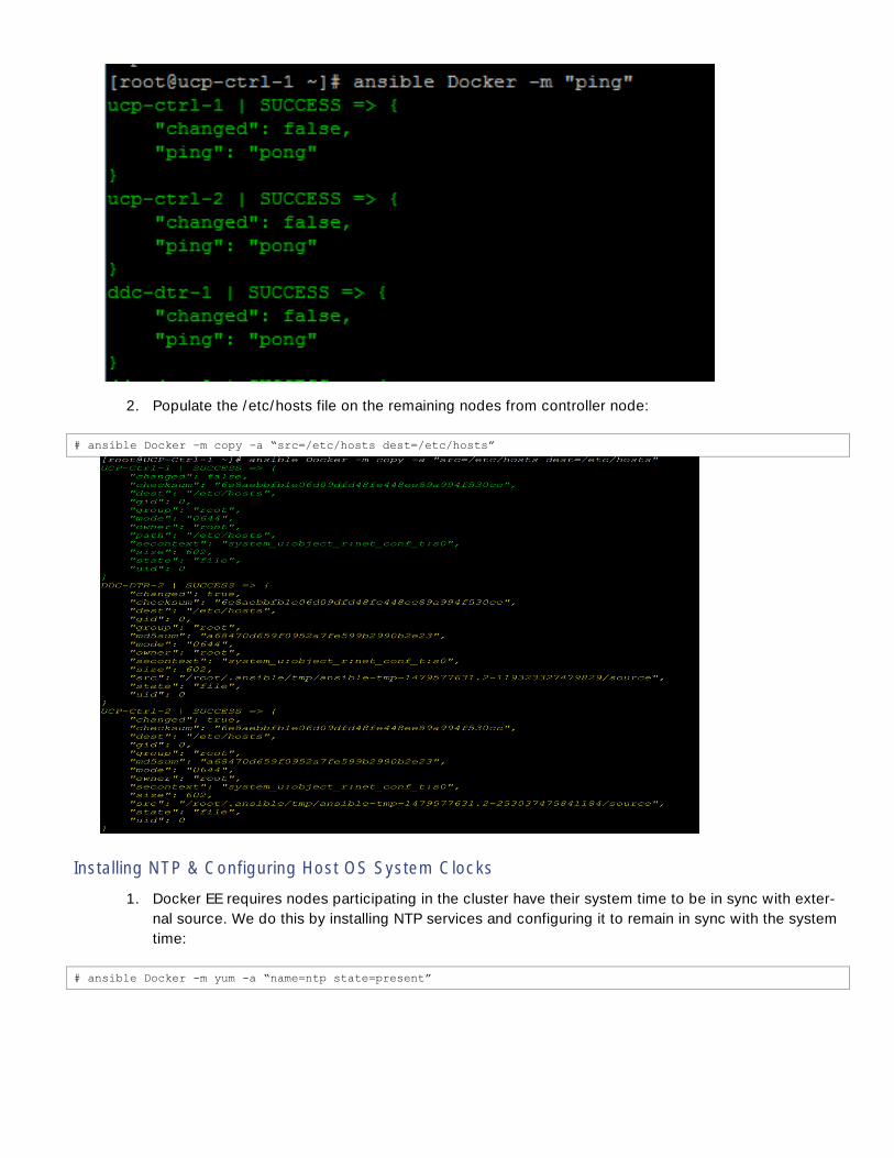
2. Populate the /etc/hosts file on the remaining nodes from controller node:
# ansible Docker –m copy –a “src=/etc/hosts dest=/etc/hosts”
Installing NTP & Configuring Host OS System Clocks
1. Docker EE requires nodes participating in the cluster have their system time to be in sync with exter-
nal source. We do this by installing NTP services and configuring it to remain in sync with the system
time:
# ansible Docker -m yum -a “name=ntp state=present”

2. Add your NTP source in /etc/ntp.conf file and copy the file to all other nodes:
3. Copy the conf file to all the other nodes:
[root@UCP-Ctrl-1 ~]# ansible Docker -m copy -a “src=/etc/ntp.conf dest=/etc/ntp.conf”
4. Enable NTPD and start the service on the all the nodes, followed by status check to make sure sys-
tem clocks are in sync on all the nodes:
[root@UCP-Ctrl-1 ~]# ansible Docker -a “/usr/bin/systemctl enable ntpd.service”
[root@UCP-Ctrl-1 ~]# ansible Docker -a “/usr/bin/systemctl start ntpd.service”
[root@UCP-Ctrl-1 ~]# ansible Docker -a “/usr/bin/systemctl status ntpd.service”
5. Querying the NTP source to check on the clock-skew if any:
[root@UCP-Ctrl-1 ~]# ansible Docker -a “/usr/sbin/ntpdate -q 10.1.156.4”

Installing Cisco Virtual Interface Card (VIC) eNIC (Ethernet Network Interface Card) and fNIC
Driver
RHEL 7.3 comes with inbox eNIC and fNIC drivers for the Cisco VIC, but we need to update them to the
latest corresponding versions for the UCS Manager release used in the solution. RPMs needs to be extracted
from the appropriate downloaded Cisco UCS B-Series Server Software bundle from cisco.com.
1. Installing of eNIC and fnic drivers can be done through rpm install and this requires host reboot.
2. Copy the two rpm files to the /tmp directory on UCP Controller 1.
3. Copy the rpm files to all the nodes using Ansible:
[root@UCP-Ctrl-1 ~]# ansible Docker -m copy -a "src=/tmp/kmod-enic-2.3.0.30-rhel7u3.el7.x86_64.rpm
dest=/root/kmod-enic-2.3.0.30-rhel7u3.el7.x86_64.rpm"
[root@UCP-Ctrl-1 ~]# ansible Docker -m copy -a "src=/tmp/kmod-fnic-1.6.0.30-rhel7u3.el7.x86_64.rpm
dest=/root/kmod-fnic-1.6.0.30-rhel7u3.el7.x86_64.rpm”
4. Use the yum module to install the eNIC and fnic driver rpm file on all node through Ansible:
[root@UCP-Ctrl-1 ~]# ansible Docker –m yum –a “name=/root/kmod-enic-2.3.0.30-rhel7u3.el7.x86_64.rpm
state=present”
[root@UCP-Ctrl-1 ~]# ansible Docker –m yum –a “name=/root/kmod-fnic-1.6.0.27-rhel7u3.el7.x86_64.rpm
state=present”

5. Reboot all the nodes after installing the latest enic and fnic drivers:
[root@UCP-Ctrl-1 ~]# ansible Docker –a “/usr/sbin/shutdown –r +1”
Configuring Host OS Firewall for required ports
Docker EE requires some TCP and UDP ports to be opened to facilitate communication between its container
infrastructure services running on cluster nodes. This needs to be done before installing Docker CS Engine
and the Docker UCP. - -
shown below. For every port type such as TCP and UDP, refer the table below to see the specific ports to be
opened and then making them permanent on the host.
Table 20. TCP and UDP ports to be opened on hosts for Docker UCP
Hosts Direction Port Purpose
controllers, nodes in TCP 443 (configurable) Web app and CLI client
access to UCP.
controllers, nodes in TCP 2375 Heartbeat for nodes, to
ensure they are running.
controllers in TCP 2376 (configurable) Swarm manager accepts
requests from UCP
controller.
controllers, nodes in, out TCP + UDP 4789 Overlay networking.
controllers, nodes in, out TCP + UDP 7946 Overlay networking.

controllers, nodes in TCP 12376 Proxy for TLS, provides
access to UCP, Swarm, and
Engine.
controller in TCP 12379 Internal node configuration,
cluster configuration, and
HA.
controller in TCP 12380 Internal node configuration,
cluster configuration, and
HA.
controller in TCP 12381 Proxy for TLS, provides
access to UCP.
controller in TCP 12382 Manages TLS and requests
from swarm manager.
controller in TCP 12383 Used by the authentication
storage backend.
controller in TCP 12384 Used by authentication
storage backend for
replication across controllers.
controller in TCP 12385 The port where the
authentication API is
exposed.
controller in TCP 12386 Used by the authentication
worker.
1. Run the following linux command to open firewall using ansible in all the hosts.
[root@UCP-Ctrl-1 ~]# ansible Docker -a "/usr/bin/firewall-cmd --permanent --zone=public --add-port=443/tcp"
[root@UCP-Ctrl-1 ~]# ansible Docker -a "/usr/bin/firewall-cmd --permanent --zone=public --add-port=2375-
2376/tcp"
[root@UCP-Ctrl-1 ~]# ansible Docker -a "/usr/bin/firewall-cmd --permanent --zone=public --add-port=4789/udp"
[root@UCP-Ctrl-1 ~]# ansible Docker -a "/usr/bin/firewall-cmd --permanent --zone=public --add-port=4789/tcp"
[root@UCP-Ctrl-1 ~]# ansible Docker -a "/usr/bin/firewall-cmd --permanent --zone=public --add-port=12379-
12385/tcp"
# ansible Docker -a "/usr/bin/firewall-cmd --permanent --zone=public --add-port=2377/tcp"
# ansible Docker -a "/usr/bin/firewall-cmd --permanent --zone=public --add-port=7946/tcp"
# ansible Docker -a "/usr/bin/firewall-cmd --permanent --zone=public --add-port=7946/udp"
# ansible Docker -a "/usr/bin/firewall-cmd --permanent --zone=public --add-port=12386/tcp"
# ansible Docker -a "/usr/bin/firewall-cmd --permanent --zone=public --add-port=12387/tcp"
# ansible Docker -a "/usr/bin/firewall-cmd --permanent --zone=public --add-port=12376/tcp"
2. Restart the firewall service as below:
[root@UCP-Ctrl-1 ~]# ansible Docker -a "/usr/bin/systemctl restart firewalld.service"
3. To confirm the list of ports opened run the following command as shown below:
[root@UCP-Ctrl-1 ~]# ansible Docker -a "/usr/bin/firewall-cmd --zone=public --list-all"

Installation of Docker Repo and Docker Engine
Perform following steps to install Docker engine
Docker EE is supported on RHEL 7.2 or 7.3 64 bit.
1. Visit https://store.docker.com/search?offering=enterprise&type=edition and click Docker Enterprise
Edition for Red Hat Enterprise Linux. Copy the URL to download your Edition.
2. Setup two yum repositories in /etc/yum/vars. Store your EE repository URL in
/etc/yum/vars/dockerurl in all the hosts as below using ansible. Replace <DOCKER-EE-URL> with
the URL you copied in the above step
[root@UCP-Ctrl-1 ~]# ansible Docker -a "sh -c 'echo "<DOCKER-EE-URL>" > /etc/yum/vars/dockerurl'"
3. Store your RHEL version in /etc/yum/vars/dockerosversion. Replace the <RHEL VERSION> with
appropriate RHEL version string. For example, 7.3 in this case.
[root@UCP-Ctrl-1 ~]# ansible Docker -a "sh -c 'echo "<RHEL VERSION>" > /etc/yum/vars/dockerosversion'"
4. - -config-manager utility:
[root@UCP-Ctrl-1 ~]# ansible Docker -m yum -a "name=yum-utils state=present"
5. Use the following command to add the stable repository. Replace the <DOCKER-EE-URL>
[root@UCP-Ctrl-1 ~]# ansible Docker -a "yum-config-manager --add-repo <DOCKER-EE-URL>/docker-ee.repo"
6. Update the yum cache
[root@UCP-Ctrl-1 ~]# ansible Docker -a "yum makecache fast"
7. Install the Docker EE
[root@UCP-Ctrl-1 ~]# ansible Docker -a "yum -y install docker-ee"
8. Verify that all the nodes have Docker Engine installed successfully
[root@UCP-Ctrl-1 ~]# ansible Docker -a "/usr/bin/yum info docker-ee"
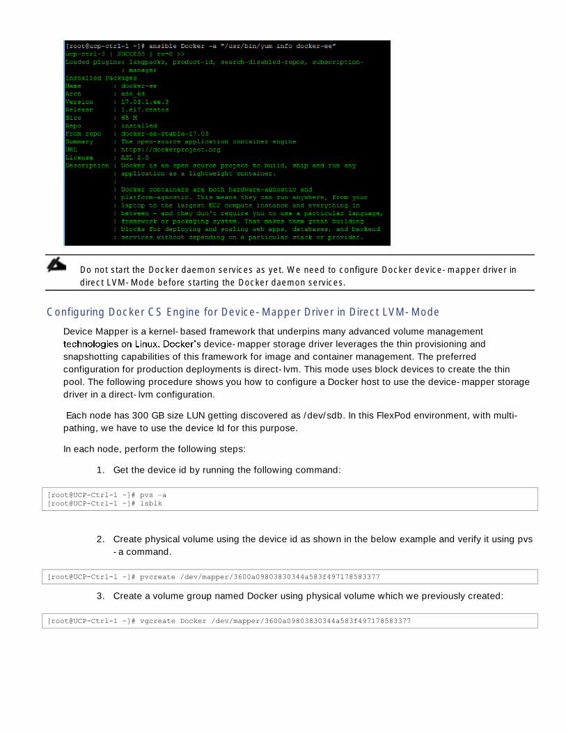
Do not start the Docker daemon services as yet. We need to configure Docker device-mapper driver in
direct LVM-Mode before starting the Docker daemon services.
Configuring Docker CS Engine for Device-Mapper Driver in Direct LVM-Mode
Device Mapper is a kernel-based framework that underpins many advanced volume management
device-mapper storage driver leverages the thin provisioning and
snapshotting capabilities of this framework for image and container management. The preferred
configuration for production deployments is direct-lvm. This mode uses block devices to create the thin
pool. The following procedure shows you how to configure a Docker host to use the device-mapper storage
driver in a direct-lvm configuration.
Each node has 300 GB size LUN getting discovered as /dev/sdb. In this FlexPod environment, with multi-
pathing, we have to use the device Id for this purpose.
In each node, perform the following steps:
1. Get the device id by running the following command:
[root@UCP-Ctrl-1 ~]# pvs –a
[root@UCP-Ctrl-1 ~]# lsblk
2. Create physical volume using the device id as shown in the below example and verify it using pvs
-a command.
[root@UCP-Ctrl-1 ~]# pvcreate /dev/mapper/3600a09803830344a583f497178583377
3. Create a volume group named Docker using physical volume which we previously created:
[root@UCP-Ctrl-1 ~]# vgcreate Docker /dev/mapper/3600a09803830344a583f497178583377
4. Create a logical volume named thinpool and thinpoolmeta. In this example, the logical data is
i-
ther the data or metadata if space runs low.
[root@UCP-Ctrl-1 ~]# ansible Docker -a "/usr/sbin/lvcreate --wipesignatures y -n thinpool Docker -l 95%VG" [root@UCP-Ctrl-1 ~]# ansible Docker -a "/usr/sbin/lvcreate --wipesignatures y -n thinpoolmeta Docker -l 1%VG"
5. Convert the pool to a thinpool:
[root@UCP-Ctrl-1 ~]# ansible Docker -a "/usr/sbin/lvconvert -y --zero n -c 512K --thinpool Docker/thinpool -
-poolmetadata Docker/thinpoolmeta"
6. Configure auto-execution of thin pool via lvm profile.
value.The value should be the percentage of space used before lvm attempts to autoextend the
available space (100 = disabled). Modify the thin_pool_autoextend_percent for when thin pool
autoextension occurs.
(100 = disabled). Docker-thinpool.profile should appear as below
[root@UCP-Ctrl-1 ~]# vi /etc/lvm/profile/docker-thinpool.profile
activation {
thin_pool_autoextend_threshold=80
thin_pool_autoextend_percent=20
}
7. Copy the docker-thinpool.profile to all the hosts.
# ansible Docker -m copy -a “src=/etc/lvm/profile/docker-thinpool.profile dest=/etc/lvm/profile/docker-
thinpool.profile”
8. Apply the newly created lvm-profile
[root@UCP-Ctrl-1 ~]# ansible Docker -a "/usr/sbin/lvchange --metadataprofile docker-thinpool Docker/thinpool"
9. Verify lv is monitored in all the nodes through ansible
[root@UCP-Ctrl-1 ~]# ansible Docker -a "/usr/sbin/lvs -o+seg_monitor"
10. Configure Docker daemon with specific device-mapper options. Now that storage is configured
we need to tell Docker daemon to use it. We do this by creating daemon.jason file with the fol-
lowing configuration parameters and place it as /etc/docker/daemon.json. create a directory if
/etc/docker does not exists.
# vi /etc/docker/daemon.json
{
"storage-driver": "devicemapper",
"storage-opts": [
"dm.thinpooldev=/dev/mapper/Docker-thinpool",
"dm.use_deferred_removal=true",
"dm.use_deferred_deletion=true"
]

}
11. If /etc/docker does not exist, create it before-hand on all the nodes and copy the daemon.json:
[root@UCP-Ctrl-1 ~]# ansible Docker -a "/usr/bin/mkdir /etc/docker"
12. Copy /etc/docker/daemon.json to all the nodes using ansible as below:
[root@UCP-Ctrl-1 ~]# ansible Docker -m copy -a "src=/etc/docker/daemon.json dest=/etc/docker/daemon.json"
13. Enable Docker service and start the service on all the nodes:
[root@UCP-Ctrl-1 ~]# ansible Docker -a "/usr/bin/systemctl enable docker.service"
[root@UCP-Ctrl-1 ~]# ansible Docker -a "/usr/bin/systemctl start docker.service"
14. Verify that Docker service is up and running on all the nodes:
[root@UCP-Ctrl-1 ~]# ansible Docker -a "/usr/bin/systemctl status docker.service"
15. Verify that the Docker service is running with storage driver set to device-mapper:
[root@UCP-Ctrl-1 ~]# ansible Docker -a "/usr/bin/docker info"

16. Check that the LVs are monitored as configured:
[root@UCP-Ctrl-1 ~]# journalctl -fu dm-event.service
17. s-
ter nodes:
[root@UCP-Ctrl-1 ~]# ansible Docker -a "/usr/bin/docker ps"

18. With this all the cluster nodes are installed with Docker CS Engine and they are configured for in-
stalling Docker UCP and DTR services.
Install and Configure Docker UCP Controller Nodes
1. Docker UCP is a containerized application that requires Docker CS Engine 1.10.0 or above to run.
Installation work flow is split into two steps. We identify the first UCP Controller node, install UCP
on it and then start adding UCP Controller replicas and UCP Nodes. This way they form a large
cluster running Docker EE. Docker Trusted Registry is again a containerized application running
on one of the UCP nodes.
2. Docker UCP installation is one single command as shown below:
[root@UCP-Ctrl-1 ~]# docker run --rm -it --name ucp -v /var/run/docker.sock:/var/run/docker.sock docker/ucp
install -i --host-address 192.168.91.21
3. This command takes the following parameters:
Container name: --name ucp
UCP version tag: docker/ucp:<VERSION>
UCP release tagging is important, as we are specifically saying what version needed to be in-
s
UCP URL/Host address: --host-addres <ip-address of the 1st Controller Node>
License file can also be specified with the v parameter during install time such as -v <path>/docker_subscription.lic:/docker_subscription.lic
4. Check that the UCP web application is running. Open the browser and navigate to the address
where UCP is installed

5. Now that UCP is installed. It is important to license it.
6.
of how to license your installation, please visit:
https://store.docker.com/editions/enterprise/docker-ee-server-rhel/purchase
Add UCP Replicas
1. Login to UCP controller GUI
2. Click ResourceNodesAdd Node
3. Pop-
4. Copy docker swarm join command in the clip board as shown in Figure

5. Login to the UCP Controller node and execute the docker swarm join command from the Clip-
board to add the second UCP node
6. Repeat to add third UCP controller replica.
7. After the third node has joined we need to restart the Docker services on controller nodes one by
one, starting from the first UCP controller node.
8. All the three nodes joins to form a cluster, Docker UCP dashboard will show three active manag-
ers.
Add UCP Nodes
In this step we will now continue to add rest of the 7 hosts to the newly formed cluster. Even the DTR nodes
will be added as UCP worker nodes first. For all the remaining nodes, command will be same.
Perform the following steps to add worker nodes:
1. Login UCP controller
2. Click ResourcesNodes+ Add Node
3. Leave everything unchecked.
4. Copy docker swarm join command to the Clipboard by clicking
shown

5. Login to the UCP node and execute the docker swarm join command from the Clipboard to add
worker node.
6. Repeat the same for all the seven worker nodes.
7. After all the nodes join the cluster, the UCP Dash board should look as shown in the screenshot
below:
Install and Configure DTR and its Replicas
1. Install DTR application on the designated DTR nodes such as DTR1, DTR2 and DTR3.
2. Open port 80 on all cluster nodes and restart firewalld service as below.
[root@UCP-Ctrl-1 ~]# ansible Docker -a "/usr/bin/firewall-cmd --permanent --zone=public –add-port=80/tcp"

[root@UCP-Ctrl-1 ~]# ansible Docker -a "/usr/bin/systemctl restart firewalld.service"
3. Execute the following on the first UCP controller node to install the DTR node
[root@UCP-Ctrl-1 ~]# docker run --rm -it docker/dtr install --ucp-url https://192.168.91.21:443 --ucp-node
DDC-DTR-1.vikings.cisco.com --dtr-external-url 192.168.91.24 --ucp-username <UCP-USERNAME> --ucp-password
<UCP-PASSWORD> --ucp-insecure-tls --nfs-storage-url nfs://192.168.92.11/DTR-NFS
4. Following parameters are used in the command
Specific DTR versioning tag docker/dtr:<VERSION>. Specify docker/dtr for latest version
UCP URL 1st UCP Controller URL --ucp-url https://<ip-address>
UCP Node - --ucp-node <1st DTR Node FQDN>
DTR External URL - --dtr-external-url <ip address of the 1st DTR Node>
UCP CA Certs - --ucp-ca <cert file with path where we downloaded certs using curl>
UCP Insecure Tls --ucp-insecure-tls <tells the installer to trust the certificates used by the
UCP>
NFS Storage URL
5. Join other DTR Nodes as DTR replicas by using the replica id from the outcome of first DTR
node. Run the following command in the UCP controller node. Nfs tag is not required for joining
nodes.
[root@UCP-Ctrl-1 ~]# docker run --rm -it docker/dtr join --ucp-url https://192.168.91.21:443 --ucp-node DDC-
DTR-2.vikings.cisco.com --existing-replica-id 75180d732196 --ucp-username <UCP-USERNAME> --ucp-password
<UCP-PASSWORD> --ucp-insecure-tls
Here we added --existing-replica-id <id as provided at the of the first DTR Node addition>
6. We will now add the DTR application to the third DTR Node:
[root@UCP-Ctrl-1 ~]# docker run --rm -it docker/dtr join --ucp-url https://192.168.91.21:443 --ucp-node DDC-
DTR-3.vikings.cisco.com --existing-replica-id 75180d732196 --ucp-username <UCP_USERNAME> --ucp-password
<UCP-PASSWORD> --ucp-insecure-tls
7. Check that DTR containers running on DTR Nodes in UCP GUI.

8. Login to DTR URL (which is the first DTR Node ip address):
Docker recommends using external load balancer VIP address in Domain section shown in Figure.
ip address.
9. Next step is to configure NFS file system on all three DTR Nodes to have the shared access.
a. Check nfs-utils is installed in DTR nodes. If not install nfs-utils using # yum install nfs-utils
b. Open firewall ports for NFS services on DTR nodes only and restart firewalld service:
[root@UCP-Ctrl-1 ~]# ansible DTR -a "firewall-cmd --permanent --zone=public --add-service=nfs"
[root@UCP-Ctrl-1 ~]# ansible DTR -a "firewall-cmd --permanent --zone=public --add-service=mountd"

[root@UCP-Ctrl-1 ~]# ansible DTR -a "firewall-cmd --permanent --zone=public --add-service=rpc-bind"
[root@UCP-Ctrl-1 ~]# ansible DTR -a "systemctl restart firewalld.service"
10. NFS share is setup during DTR install and join commands. verify external NFS file share on all the
three DTR Nodes as shown below:
[root@DDC-DTR-1 ~]# mount | grep DTR
NFS mount point should be /var/lib/docker/volumes/dtr-registry-nfs-<DTR Replica id>/_data
11. NFS storage back-end can also be verified in DTR GUI by clicking SettingsStorage as shown
Configure NetApp Docker Volume Plugin (nDVP)
1. Perform the following steps to setup the NetApp Docker Volume Plugin (nDVP)
2. Verify that Docker version is 17.03 or above.
# docker --version

3. Create a location for the config files
[root@UCP-Ctrl-1 ~]# ansible Docker -a "mkdir -p /etc/netappdvp"
4. Create a configuration files
[root@UCP-Ctrl-1 netappdvp]# vi /etc/netappdvp/netapp-nas-tnt-a-01.json
{
"version": 1,
"storageDriverName": "ontap-nas",
"storagePrefix": "netappdvp",
"managementLIF": "192.168.91.11",
"dataLIF": "192.168.93.11",
"svm": "Cntr-TNT-A-SVM",
"username": "ndvp_user",
"password": "H1ghV0lt",
"aggregate": "aggr1_node01"
[root@UCP-Ctrl-1 netappdvp]# vi /etc/netappdvp/netapp-nas-tnt-a-02.json
{
"version": 1,
"storageDriverName": "ontap-nas",
"storagePrefix": "netappdvp",
"managementLIF": "192.168.91.11",
"dataLIF": "192.168.93.12",
"svm": "Cntr-TNT-A-SVM",
"username": "ndvp_user",
"password": "H1ghV0lt",
"aggregate": "aggr1_node02"
}
The above config creates nDVP instances using the default storage prefix name. The storagePrefix
parameter in the configuration file can be modified as needed for monitoring and reporting. For ex-
FlexVols corresponding to the Docker volumes created using this nDVP instance would then have a
5. Copy the .json configuration files to all the hosts as below
# ansible Docker -m copy -a "src=/etc/netappdvp/netapp-nas-tnt-a-01.json dest=/etc/netappdvp/netapp-nas-tnt-
a-01.json"
# ansible Docker -m copy -a "src=/etc/netappdvp/netapp-nas-tnt-a-02.json dest=/etc/netappdvp/netapp-nas-tnt-
a-02.json"
6. Start nDVP using the managed plugin system
# ansible Docker -a "docker plugin install store/netapp/ndvp-plugin:1.4.0 --alias netapp-nas-tnt-a-01
config=netapp-nas-tnt-a-01.json --grant-all-permissions" # ansible Docker -a "docker plugin install store/netapp/ndvp-plugin:1.4.0 --alias netapp-nas-tnt-a-02
config=netapp-nas-tnt-a-02.json --grant-all-permissions"

7. Verify that plugin has been install by the running the following command.
# docker plugin ls
8. After the service is started, volumes can be created and managed via Docker CLI
# docker volume create -d netapp-nas-tnt-a-01 --name demo_vol
# docker volume ls | grep demo_vol
# docker volume inspect demo_vol

9. Below figure shows that volume is mounted in all the hosts and its mount point can be verified in
the hosts at /var/lib/docker-volumes directory.
10. verify that the volume is provisioned on
NetApp storage through the plugin as shown in the figure.
# ssh [email protected] volume show -volume *demo_vol* -fields volume,size
For more information about NetApp Docker Volume Plugin (ndvp) visit here. nDVP will also be
covered as part of FlexPod Cooperative Support at a future date. Until then, please redirect any
issues to the project GitHub page / the Slack channels for nDVP
Now create a container using the volume created above and place a data file in the volume

# docker run -itd --name demo-container --volume-driver netapp-nas-tnt-a-01 --volume demo_vol:/vol_01 busybox
# docker ps | grep demo
# docker exec demo-container touch /vol_01/Persistent-Data.txt
# docker exec demo-container ls /vol_01
11. Using an external, enterprise class, storage array for the application data is important for a num-
ber of reasons, not the least of which is data protection. Storage arrays are designed for high
availability and to assure the integrity of the data being stored. The volume can also be cloned to
setup development environment as mentioned in the following steps.
12. Clone the volume and mount it in all the host by running the following docker commands.
# docker volume create -d netapp-nas-tnt-a-01 --name demo_vol_clone -o from=demo_vol
# docker volume ls | grep demo_vol_clone
13. Notice that the cloned volume only appears once, this is intended behaviour. Once the volume is
created and mounted, it can also be verified in storage array as shown below.
# ssh [email protected] volume show -volume *demo_vol* -fields volume,clone-parent-name
14. Now create a container from the cloned volume and look for the added data in the cloned vol-
ume.
# docker run -itd --name demo-container-clone --volume-driver netapp-nas-tnt-a-01 --volume
demo_vol_clone:/vol_0 busybox
# docker ps | grep demo-container-clone
# docker exec demo-container-clone ls /vol_0
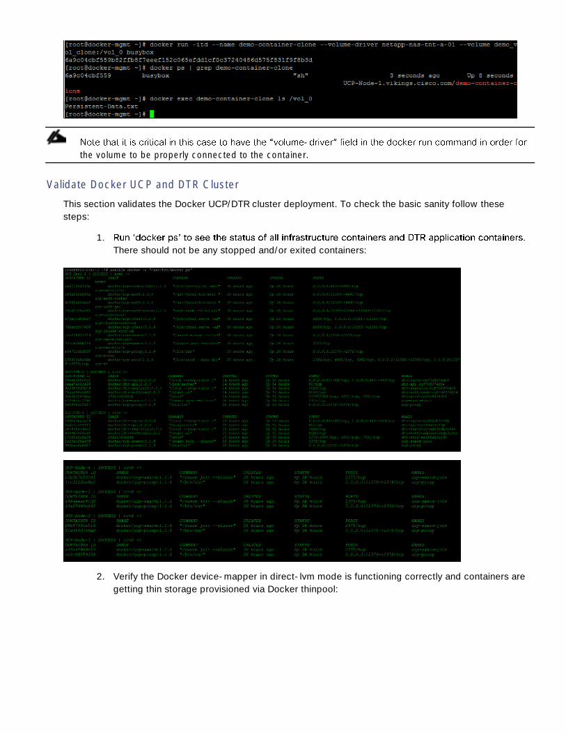
-
the volume to be properly connected to the container.
Validate Docker UCP and DTR Cluster
This section validates the Docker UCP/DTR cluster deployment. To check the basic sanity follow these
steps:
1.
There should not be any stopped and/or exited containers:
2. Verify the Docker device-mapper in direct-lvm mode is functioning correctly and containers are
getting thin storage provisioned via Docker thinpool:


Solution Validation
Application Container Deployment
To validate this solution we have performed some feature functional tests, high-availability tests, stack
scale-up and scale-down tests. Feature functional tests included routine container life-cycle management
operations through Docker UCP client bundle and GUI. Basic operation covers, creating containers,
start/stop of containers, killing containers, creating network, and using the created networks for running
containers. Docker UCP client requires Docker Toolbox to be installed on mac or windows client machine.
Docker Toolbox provides tools such as Docker Compose, Docker command line environment along with the
others. The following test validation tasks were accomplished using these tools whenever required. Docker
Toolbox can be obtained from below URLs:
Docker Toolbox Overview - https://docs.docker.com/toolbox/overview/
Docker for Mac or Windows - https://www.docker.com/products/docker-toolbox
Docker client bundle can be installed on a mac or windows box where Docker Toolbox has been installed. It
can also be run on any of the UCP Controller, DTR or UCP nodes, without having to install the Docker
Toolbox.
Procedure to install Docker client bundle is simple. Follow these steps to download the client bundle:
1. Download the client bundle from Docker UCP GUI by navigating to admin > Profile > Create a Cli-
ent Bundle.
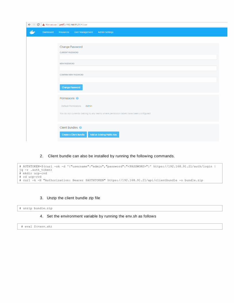
2. Client bundle can also be installed by running the following commands.
# AUTHTOKEN=$(curl -sk -d '{"username":"admin","password":"<PASSWORD>"}' https://192.168.91.21/auth/login |
jq -r .auth_token)
# mkdir ucp-cvd
# cd ucp-cvd
# curl -k -H "Authorization: Bearer $AUTHTOKEN" https://192.168.91.21/api/clientbundle -o bundle.zip
3. Unzip the client bundle zip file
# unzip bundle.zip
4. Set the environment variable by running the env.sh as follows
# eval $(<env.sh)

5. Run docker info to see if client bundle is working.
# docker info
6. Now you are good to use the client, as shown in above example. Setting up environment variable
enables you to use your admin credential to connect to your deployed Docker EE. Once the envi-
ronment is set, you can do all container management operations through Docker shell commands
sitting outside the Docker UCP cluster itself.
Container Networks
There are various ways in which container-to-container and container-to-host connectivity is provided. This
sub-section provides details on the container networking types supported for Docker containers:

None None is a simple mode of container networking. In this the deployed container receives a
network stack, which lacks an external network interface; but does receive a loopback interface. This
mode of container networking is mainly used for testing and staging a container and where container
does not need external communications.
Bridge A Linux bridge provides a host internal network in which containers on the same host may
communicate, but the IP address assigned to them are not accessible from outside of the host.
Bridge networking leverages iptables for NAT and port-mapping thus providing single host
networking. Bridge network is a default Docker network type, for example, docker0 is a bridge name
where one end of a virtual network interface pair is connected between the bridge and the container.
NAT is used to provide communication beyond the host. Bridge networking solves the problems of
port-conflict and also solves performance over head associated using NAT. It also provides isolation
to containers running on one host.
Figure 11. Bridge Network
The first image in the figure shows how a bridge network communicates and the adjacent images
shows how a service on Container-2 gets exposed to outside world via host port 8080 mapped to
port 80 on the container.
Host In this type of network, a newly created container shares its network namespace with the
host, providing higher performance and eliminating the need for NAT. The bottle-neck in this type of
network is port-conflicts and since container has full-access to hosts interfaces it run into security
risks.

Figure 12. Host Network
Overlay It uses networking tunnels to deliver communication across hosts. This allows containers
to behave as if they are on the same host by tunneling network subnets from one host to the other.
Essentially, it is like spanning one network across multiple hosts. VxLAN encapsulation is the
tunneling choice for Docker libnetworks. Multi-host networking requires additional parameters when
launching Docker daemon, as well as a key-value store. Overlay networks focus on the cross-host
communication challenge. Containers on the same host that are connected to two different overlay
networks cannot communicate with each other via local bridge they are segmented from one
another.
Figure 13. Overlay Network
Deploying container/application container using overlay network
Follow these steps to deploy container/application container using overlay network:

1. Log in to any Linux machine with Docker UCP client bundle installed. To list out existing available
networks, run the
# docker network ls
2. For creating an overlay network, we need to specify the overlay driver and the network name as
shown below:
# docker network create --driver overlay --subnet 10.0.2.0/24 my-multi-host-network --attachable
Docker Engine running in Swarm mode, you can create overlay attachable network on a manager node. -
attachable option is not available in Docker client.
creating the network we can verify its successful creation by listing available networks. The last column
as shown in the screenshot above lists the scope of the network cr
cluster.
3.
# docker network inspect my-multi-host-network

4. Deploy a container by running the following command
# docker volume create -d netapp-nas-tnt-a-01 --name my_busybox
# docker run -itd --name my-busybox-c1 --volume-driver netapp-nas-tnt-a-01 --volume my_busybox:/disk_01 --
network my-multi-host-network busybox
Above command will provision container with the volume in NetApp NFS backend and attached it to the
overlay network. Container volume specified in the docker run command can be verified in NetApp
OnCommand System Manager as shown in the Figure by running the following command.
ssh [email protected] volume show -volume *my_busybox -fields volume,clone-parent-name
5. Create another container in different host to establish container communication.
# docker volume create -d netapp-nas-tnt-a-01 --name my_busybox_vol2
# docker run -itd --name my-busybox-c2 --volume-driver netapp-nas-tnt-a-01 --volume my_busybox_vol2:/disk_01
--network my-multi-host-network busybox
6. Run the docker ps command to see if the two containers are created in two different nodes as
shown.
# docker ps | grep my-busybox

7. Let us check the network stack created inside the container to verify that the interface is
plumbed correctly and it gets the ip address from the subnet we have specified earlier and the
docker exec my-busybox-c1 ifconfig
8. i-
fy its reachability and make sure that it can ping the external gateway which is 10.0.2.2 from
docker network inspect my-multi-host-network output.
# docker exec my-busybox-c1 ping 10.0.2.2

9. Now look at the ip address of the second container by running the following command.
# docker exec my-busybox-c2 ifconfig
10. To verify if both the container communicates on an overlay network, run ping from container 1 to
container 2 IP address which is 10.0.2.4. A successful ping is observed between the containers
running in different hosts connected via overlay network.
# docker exec my-busybox-c1 ping 10.0.2.4
11. -mapping done for httpd services, in
order to access its web-service from the upstream network:

# docker volume create -d netapp-nas-tnt-a-01 --name nginx_vol_01
# docker run -itd --name Nginx-Overlay --volume-driver netapp-nas-tnt-a-01 --volume nginx_vol_01:/disk_01 --
network my-multi-host-network -p 5555:80 nginx
# docker ps | grep Nginx
We have - port-mapper switch to deploy an
-Node-3 host.
12. Open https://192.168.91.21 in a web browser to login to the Docker UCP. The Resources tab
13. Open 192.168.91.30:5555 in a web browser. With the port-mapping in place, we can reach our
nginx web-server from outside world, by accessing the port#5555 as shown below:

DTR Operations
This section details about validating the Docker Trusted Registry workflow. As mentioned earlier, DTR
provides a way to create a repository of Docker images used for container deployment locally for the
enterprise. This eliminates the need for accessing external repos in public domain for downloading images
for the containers. This option provides a better control on deploying images for the enterprise and secures
application container environment.
1.
repository:
2.
download the image from the Docker public repo:
# docker pull busybox
The downloaded image gets pulled to all our cluster nodes as shown in the screenshot above. This ena-
bles us to run the container using this image on any of the host.
3. To list all the images that we have on
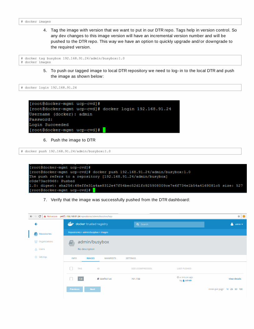
# docker images
4. Tag the image with version that we want to put in our DTR repo. Tags help in version control. So
any dev changes to this image version will have an incremental version number and will be
pushed to the DTR repo. This way we have an option to quickly upgrade and/or downgrade to
the required version.
# docker tag busybox 192.168.91.24/admin/busybox:1.0
# docker images
5. To push our tagged image to local DTR repository we need to log-in to the local DTR and push
the image as shown below:
# docker login 192.168.91.24
6. Push the image to DTR
# docker push 192.168.91.24/admin/busybox:1.0
7. Verify that the image was successfully pushed from the DTR dashboard:

8. Click INFO tab to get the command to pull this image from the local repo for deployment:
9. Now validate the container deployment using local DTR image repo:
# docker run -it --name dtr-test-busybox 192.168.91.24/admin/busybox:1.0
Showing Container Survivability Using Docker Swarm
If a container is cre
container has High Availability. If the node that the container is running on fails, the container and its
persistent data volumes mapped with the NetApp Docker Volume Plugin will immediately be brought up on
another node in the Swarm.
1. Return to the demo-container created with docker volume demo_vol created earlier, and stop
and remove the container.
# docker ps | grep demo-container
# docker stop demo-container
# docker rm demo-container
2. Create a docker service with one replica and with demo_vol mapped into anNGINX instance.
Check for the launch of the service.

# docker service create -p 5915:80 --name demo-svc --mount volume-driver=netapp-nas-tnt-a-
01,source=demo_vol,destination=/usr/share/nginx/html/data nginx
# docker service ls
# docker ps | grep demo-svc
3. Make sure the file added earlier is still in demo_vol.
# docker exec <container-id> ls /usr/share/nginx/html/data
4. Reboot the host the container is running on and verify that the container is brought up on another
node.
# ssh root@ucp-node-1 reboot
# docker ps | grep demo-svc – Run this repeatibly until you see the second container running.

5. Verify the persistent data in the new container.
# docker exec <new-container-id> ls /usr/share/nginx/html/data

Storage Utilization using a non-admin DDE User
Storage level isolation among multiple tenants is achieved through dedicated SVM associated per tenant.
This allows us to limit the number of volumes, storage tiers, QoS on a per-tenant basis.
Create a following nDVP instance for a CRM team.
[root@ucp-ctrl-1 netappdvp]# vi netapp-nas-tnt-a-crm.json
{
"version": 1,
"storageDriverName": "ontap-nas",
"storagePrefix": "crm",
"managementLIF": "192.168.91.11",
"dataLIF": "192.168.93.12",
"svm": "Cntr-TNT-A-SVM",
"username": "ndvp_user",
"password": "H1ghV0lt",
"aggregate": "aggr1_node02"
}
1. Copy the .json file to all the hosts using ansible as shown
# ansible Docker -m copy -a "src=/etc/netappdvp/netapp-nas-tnt-a-crm.json dest=/etc/netappdvp/netapp-nas-tnt-
a-crm.json"
2. Include the nDVP instance into service file.
# ansible Docker -a "docker plugin install store/netapp/ndvp-plugin:1.4.0 --alias netapp-nas-tnt-a-crm
config=netapp-nas-tnt-a-crm.json --grant-all-permissions"
3. John Doe .
To create a new user, go to the UCP web UI, and navigate to the User Management page.

1.
We later create com.docker.ucp.access.label associ-
ated with different privileges in the team
2. Create a team CRM and add users
To create a new user, go to the UCP web UI, and navigate to the User Management page.

1. Add John Doe user to the CRM team.
2.

The restricted control permission allows the user to view and create resources with this label.
3. Log in into UCP Control Plane as Jon Doe user and create a volume.

4. Verify that the volume crmbilling is created on ONTAP.

Summary
The emergence of the Docker platform and the underlying support in the Linux and Windows has enabled a
shift in the way that traditional applications are managed and new applications are designed and built,
moving to more efficient micro services architectures. Microservices architectures are an approach to
modernizing and building complex applications through small, independent components that communicate
with each other over language-independent APIs.
The integration of Docker Enterprise Edition with the FlexPod converged infrastructure enabled through
automation tools like UCS Python SDK and Ansible provides container application platform to get deployed
and managed quickly at scale. It also provides a very good starting point for enterprise IT to make in-roads
into DevOps and CI/CD model for application environment for quick business need turn around. By
combining Docker setup with NetApp Clustered Data ONTAP, applications are robustly protected.
Furthermore, NetApp Snapshot copies, Snap Mirror software, and FlexClone platform can also be leverage
along with application integrated data protection and data management features.
FlexPod converged infrastructure and Docker Enterprise Edition container management solution can
accelerate your IT transformation by enabling easier and faster deployments, greater flexibility, heightened
business agility, increased efficiency with lowered risk and higher ROI for enterprise customers.

About Authors
Muhammad Afzal, Engineering Architect, Cisco Systems Inc.
Muhammad Afzal is an Engineering Architect and Technical Marketing Engineer at Cisco Systems in Cisco
UCS Product Management and Datacenter Solutions Engineering. He is currently responsible for designing,
developing, and producing validated converged architectures while working collaboratively with product
partners. Previously, Afzal had been a lead architect for various cloud and data center solutions in Solution
group, where he worked closely with Cisco's large enterprise and service provider customers delivering data
center and cloud solutions. Afzal holds an MBA in finance and a BS in computer engineering.
John George, Technical Marketing Engineer, Cisco Systems, Inc.
As part of the Cisco UCS team, John George is focused on designing, developing, and validating the
FlexPod Integrated Infrastructure solution. John has worked on FlexPod for both Cisco and NetApp for over
six years. John holds a Master's degree in computer engineering from Clemson University.
Amit Borulkar, Technical Marketing Engineer, NetApp, Inc.
Amit is a Technical Marketing Engineer with Converged Infrastructure Solutions at NetApp. He has a Master s
degree in Computer Science from North Carolina State University. At NetApp, he focusses on OpenStack
reference architectures, container orchestration and infrastructure automation with open source tools on
FlexPod. While at NC State, his research interests included distributed systems and cloud computing.
Uday Shetty, Senior Software Engineer, Strategic Development, Docker, Inc.
Uday Shetty has more than 25+ years of experience in Enterprise Applications at Sun/Oracle and Docker,
working with ISVs and Strategic Partners on new technology adoptions and Refer
expertise includes C/C++, Java, J2EE, Docker Enterprise Edition for on-premise and Docker EE templates for
Cloud providers.
Acknowledgements
Rajesh Kharya, Technical Leader, Cisco Systems, Inc.
David Arnette, Sr. Technical Marketing Engineer, NetApp, Inc.
Andrew Sullivan, Technical Marketing Engineer, NetApp, Inc.

208