CVD: FlexPod Datacenter with Citrix XenDesktop 7.1 and VMware ...
276
FlexPod Datacenter with Citrix XenDesktop 7.1 and VMware vSphere 5.1 Cisco Validated Design for a 2000-Seat Virtual Desktop Infrastructure Using Citrix XenDesktop 7 .1 Built on Cisco UCS B200 M3 Blade Servers with NetApp FAS3200-Series and the VMware vSphere ESXi 5.1 Hypervisor Platform Last Updated: March 5, 2014 Building Architectures to Solve Business Problems
Transcript of CVD: FlexPod Datacenter with Citrix XenDesktop 7.1 and VMware ...
FlexPod Datacenter with Citrix XenDesktop 7.1 and VMware vSphere 5.1Cisco Validated Design for a 2000-Seat Virtual Desktop Infrastructure Using Citrix XenDesktop 7.1 Built on Cisco UCS B200 M3 Blade Servers with NetApp FAS3200-Series and the VMware vSphere ESXi 5.1 Hypervisor PlatformLast Updated: March 5, 2014
Building Architectures to Solve Business Problems
Cisco Validated Design2

4
About the Authors
n is a Principal Solutions Architect at Citrix, focusing on Desktop and Application Responsibilities include solutions validation, strategic alliances, technical content esting/benchmarking.
Reference Architect, Infrastructure and Cloud Engineering, NetApp
a Reference Architect in the NetApp Infrastructure and Cloud Engineering team and is eloping, validating, and supporting cloud infrastructure solutions that include NetApp re his current role, he supported and administered Nortel's worldwide training network structure. John holds a Master's degree in Computer Engineering from Clemson
r. Reference Architect, End User Computing, NetApp
a virtualization architect at NetApp. She designs and implements virtualization solutions gration between storage and virtualization platforms. She authors many virtualization best ployment technical papers for NetApp Solutions. Before joining NetApp, she was a
e engineer for Nortel and HP Canada. Rachel received her Doctor of Medicine (M.D.) University medical school in China and a Master Degree of Computer Science from State University in US.
x, Technical Alliance Manager, NetApp
, Senior Product Manager, NetApp
a, Technical Marketing Engineer, NetApp
ez, Technical Marketing Engineer, NetApp
, Platform Integrations Engineering Manager, NetApp
nior Solution Program Manager, NetApp
About the AuthorsMike Brennan, Sr. Technical Marketing Engineer, VDI Performance and Solutions Team Lead, Cisco Systems
Mike Brennan is a Cisco Unified Computing System architect, focusing on Virtual Desktop Infrastructure solutions with extensive experience with EMC VNX, VMware ESX/ESXi, XenDesktop and Provisioning Services. He has expert product knowledge in application and desktop virtualization across all three major hypervisor platforms, both major desktop brokers, Microsoft Windows Active Directory, User Profile Management, DNS, DHCP and Cisco networking technologies.
Frank Anderson, Principal Solutions Architect, Strategic Alliance at Citrix Systems
Frank AndersoVirtualization.creation, and t
John George,
John George isfocused on devproducts. Befoand VPN infraUniversity.
Rachel Zhu, S
Rachel Zhu is and drives intepractice and desenior softwarfrom Jiao TongNorth Carolina
Acknowledgments
Cedric Courtei
Abhinav Joshi
David La Mott
Chris Rodrigu
Troy Mangum
Kim White, Se
About the Authors
About Cisco Validated Design (CVD) Program
IM ALL WARRANTIES, INCLUDING, WITHOUT LIMITATION, THE WARRANTY OF
ILITY, FITNESS FOR A PARTICULAR PURPOSE AND NONINFRINGEMENT OR ARISING
SE OF DEALING, USAGE, OR TRADE PRACTICE. IN NO EVENT SHALL CISCO OR ITS
LIABLE FOR ANY INDIRECT, SPECIAL, CONSEQUENTIAL, OR INCIDENTAL DAMAGES,
ITHOUT LIMITATION, LOST PROFITS OR LOSS OR DAMAGE TO DATA ARISING OUT OF
ABILITY TO USE THE DESIGNS, EVEN IF CISCO OR ITS SUPPLIERS HAVE BEEN ADVISED
IBILITY OF SUCH DAMAGES.
ARE SUBJECT TO CHANGE WITHOUT NOTICE. USERS ARE SOLELY RESPONSIBLE FOR
TION OF THE DESIGNS. THE DESIGNS DO NOT CONSTITUTE THE TECHNICAL OR
SSIONAL ADVICE OF CISCO, ITS SUPPLIERS OR PARTNERS. USERS SHOULD CONSULT
CHNICAL ADVISORS BEFORE IMPLEMENTING THE DESIGNS. RESULTS MAY VARY
N FACTORS NOT TESTED BY CISCO.
Cisco Eos, Cisco Lumin, Cisco Nexus, Cisco StadiumVision, Cisco TelePresence, Cisco
co logo, DCE, and Welcome to the Human Network are trademarks; Changing the Way We
y, and Learn and Cisco Store are service marks; and Access Registrar, Aironet, AsyncOS,
eeting To You, Catalyst, CCDA, CCDP, CCIE, CCIP, CCNA, CCNP, CCSP, CCVP, Cisco, the
Internetwork Expert logo, Cisco IOS, Cisco Press, Cisco Systems, Cisco Systems Capital,
ems logo, Cisco Unity, Collaboration Without Limitation, EtherFast, EtherSwitch, Event Cen-
ollow Me Browsing, FormShare, GigaDrive, HomeLink, Internet Quotient, IOS, iPhone,
onPort, the IronPort logo, LightStream, Linksys, MediaTone, MeetingPlace, MeetingPlace
MGX, Networkers, Networking Academy, Network Registrar, PCNow, PIX, PowerPanels,
criptShare, SenderBase, SMARTnet, Spectrum Expert, StackWise, The Fastest Way to
nternet Quotient, TransPath, WebEx, and the WebEx logo are registered trademarks of
, Inc. and/or its affiliates in the United States and certain other countries.
arks mentioned in this document or website are the property of their respective owners.
word partner does not imply a partnership relationship between Cisco and any other com-
Systems, Inc. All rights reserved
About Cisco Validated Design (CVD) Program
The CVD program consists of systems and solutions designed, tested, and documented to facilitate
faster, more reliable, and more predictable customer deployments. For more information visit
http://www.cisco.com/go/designzone.
ALL DESIGNS, SPECIFICATIONS, STATEMENTS, INFORMATION, AND RECOMMENDATIONS (COLLEC-
TIVELY, "DESIGNS") IN THIS MANUAL ARE PRESENTED "AS IS," WITH ALL FAULTS. CISCO AND ITS SUP-
PLIERS DISCLA
MERCHANTAB
FROM A COUR
SUPPLIERS BE
INCLUDING, W
THE USE OR IN
OF THE POSS
THE DESIGNS
THEIR APPLICA
OTHER PROFE
THEIR OWN TE
DEPENDING O
CCDE, CCENT,
WebEx, the Cis
Work, Live, Pla
Bringing the M
Cisco Certified
the Cisco Syst
ter, Fast Step, F
iQuick Study, Ir
Chime Sound,
ProConnect, S
Increase Your I
Cisco Systems
All other tradem
The use of the
pany. (0809R)
© 2014 Cisco
5
FlexPod Datacenter for 2000 Seats of Citrix XenDesktop 7.1 on VMware vSphere 5.1
Overview
About this Document
This document provides a Cisco Validated Design (CVD) for a 2000-Seat Virtual Desktop Infrastructure using Citrix XenDesktop 7.1 built on Cisco UCS B200-M3 Blade Servers with NetApp FAS3200-series and the VMware vSphere ESXi 5.1 hypervisor platform.
The landscape of desktop virtualization is changing constantly. New, high performance Cisco UCS Blade Servers and Cisco UCS unified fabric combined with the latest generation storage system NetApp Clustered Data ONTAP® 8.2 results in a compact, powerful, reliable and efficient platform.
In addition, the advances in the Citrix XenDesktop 7.1 system, which now incorporates both traditional hosted virtual Windows 7 or Windows 8 desktops, hosted applications and hosted shared Server 2008 R2 or Server 2012 R2 server desktops (formerly delivered by Citrix XenApp), provides unparalleled scale and management simplicity while extending the Citrix HDX FlexCast models to additional mobile devices
This document provides the architecture, design and performance validation of a virtual desktop infrastructure for 2000 mixed use-case (hosted shared desktops and pooled hosted desktops) users. The infrastructure is 100 percent virtualized on VMware ESXi 5.1 with third-generation Cisco UCS B-Series B200 M3 blade servers booting through FCoE from a clustered NetApp FAS3200-series storage array. The virtual desktops are powered using Citrix Provisioning Server 7.1 and Citrix XenDesktop 7.1, with a mix of hosted shared desktops (1450) and pooled hosted virtual Windows 7 desktops (550) to support the user population. Where applicable, this document provides best practice recommendations and sizing guidelines for customer deployments of XenDesktop 7.1 on the Cisco Unified Computing System.
Corporate Headquarters:
Copyright © 2013 Cisco Systems, Inc. All rights reserv
Cisco Systems, Inc., 170 West Tasman Drive, San Jose, CA 95134-1706 USA
Overview
Audience
This document describes the architecture and deployment procedures of an infrastructure comprised of Cisco, NetApp, and VMware hypervisor and Citrix desktop virtualization products. The intended audience of this document includes, but is not limited to, sales engineers, field consultants, professional services, IT managers, partner engineering, and customers who want to deploy the solution described in this document.
Summary of Main Findings
The combination of technologies from Cisco Systems, Inc., Citrix Systems, Inc., NetApp, and VMware Inc. produced a highly efficient, robust and affordable desktop virtualization solution for a hosted virtual desktop and hosted shared desktop mixed deployment supporting different use cases. Key components of the solution included:
• This solution is Cisco's Desktop Virtualization Converged Design with FlexPod providing our customers with a turnkey physical and virtual infrastructure specifically designed to support 2000 desktop users in a highly available proven design. This architecture is well suited for large departmental and enterprise deployments of virtual desktop infrastructure.
• More power, same size. Cisco UCS B200 M3 half-width blade with dual 12-core 2.7 GHz Intel Ivy Bridge (E5-2680v2) processors and 384GB of memory supports ~25% more virtual desktop workloads than the previously released Sandy Bridge processors on the same hardware. The Intel Xeon E5-2680 v2 10-core processors used in this study provided a balance between increased per-blade capacity and cost.
• Fault-tolerance with high availability built into the design. The 2000-user design is based on using two Cisco Unified Computing System chassis with twelve Cisco UCS B200 M3 blade servers for virtualized desktop workloads and two Cisco UCS B200 M3 blades for virtualized infrastructure workloads. The design provides N+1 Server fault tolerance for hosted virtual desktops, hosted shared desktops and infrastructure services.
• Stress-tested to the limits during aggressive boot scenario. The 2000-user mixed hosted virtual desktop and hosted shared desktop environment booted and registered with the XenDesktop 7.1 Delivery Controllers in under 15 minutes, providing our customers with an extremely fast, reliable cold-start desktop virtualization system.
• Stress-tested to the limits during simulated login storms. All 2000 simulated users logged in and started running workloads up to steady state in 30-minutes without overwhelming the processors, exhausting memory or exhausting the storage subsystems, providing customers with a desktop virtualization system that can easily handle the most demanding login and startup storms.
• Ultra-condensed computing for the datacenter. The rack space required to support the 2000-user system is a single rack of approximately 32 rack units, conserving valuable data center floor space.
• Pure Virtualization: This CVD presents a validated design that is 100% virtualized on VMware ESXi 5.1. All of the virtual desktops, user data, profiles, and supporting infrastructure components, including Active Directory, Provisioning Servers, SQL Servers, XenDesktop Delivery Controllers, and XenDesktop RDS (XenApp) servers were hosted as virtual machines. This allows customers complete flexibility for maintenance and capacity additions because the entire system runs on the FlexPod converged infrastructure with stateless Cisco UCS blade servers, and NetApp unified storage with Clustered Data ONTAP.
• Cisco maintains industry leadership with the new Cisco UCS Manager 2.1.3(a) software that simplifies scaling, guarantees consistency, and eases maintenance. Cisco's ongoing development efforts with Cisco UCS Manager, Cisco UCS Central, and Cisco UCS Director helps ensure that
7FlexPod Datacenter for 2000 Seats of Citrix XenDesktop 7.1 on VMware vSphere 5.1
Overview
customer environments are consistent locally, across Cisco UCS Domains and across the globe, our software suite offers increasingly simplified operational and deployment management, and it continues to widen the span of control for customer organizations' subject matter experts in compute, storage and network.
• Our 10G unified fabric story gets additional validation on second generation 6200 Series Fabric Interconnects as Cisco runs more challenging workload testing, while maintaining unsurpassed user response times.
• NetApp FAS with Clustered Data ONTAP provides industry-leading storage solutions that efficiently handle the most demanding IO bursts (for example, login storms), profile management, and user data management, provide VM backup and restores, deliver simple and flexible business continuance, and help reduce storage cost per desktop.
• NetApp FAS provides a simple storage architecture for hosting all user data components (VMs, profiles, user data) on the same storage array.
• NetApp Clustered Data ONTAP system enables seamlessly add, upgrade or remove storage infrastructure to meet the needs of the virtual desktops.
• NetApp Virtual Storage Console for VMware (VSC) has deep integration with VMware vSphere provides easy button automation for key storage tasks like datastore provisioning, storage resize, data deduplication, backup and recovery, etc. directly from within vCenter server.
• NetApp Cluster ONTAP offers a seamless and reliable user experience during the storage node failover test.
• Latest and greatest virtual desktop and application product. Citrix XenDesktop™ 7.1 follows a new unified product architecture that supports both hosted-shared desktops and applications (RDS) and complete virtual desktops (VDI). This new XenDesktop release simplifies tasks associated with large-scale VDI management. This modular solution supports seamless delivery of Windows apps and desktops as the number of users increase. In addition, HDX enhancements help to optimize performance and improve the user experience across a variety of endpoint device types, from workstations to mobile devices including laptops, tablets, and smartphones.
• Optimized to achieve the best possible performance and scale. For hosted shared desktop sessions, the best performance was achieved when the number of vCPUs assigned to the XenDesktop 7 RDS virtual machines did not exceed the number of hyper-threaded cores available on the server. In other words, maximum performance is obtained when not over committing the CPU resources for the virtual machines running RDS.
• Provisioning desktop machines made easy. Citrix Provisioning Services created hosted virtual desktops as well as hosted shared desktops for this solution using a single method for both, the “PVS XenDesktop Setup Wizard.”
Solution Component Benefits
Each of the components of the overall solution materially contributes to the value of functional design contained in this document.
8FlexPod Datacenter for 2000 Seats of Citrix XenDesktop 7.1 on VMware vSphere 5.1
Overview
Benefits of Cisco Unified Computing System
Cisco Unified Computing System™ (UCS) is the first converged data center platform that combines industry-standard, x86-architecture servers with networking and storage access into a single converged system. The system is entirely programmable using unified, model-based management to simplify and speed deployment of enterprise-class applications and services running in bare-metal, virtualized, and cloud computing environments.
Benefits of the Cisco Unified Computing System include:
Architectural Flexibility
• Cisco UCS B-Series blade servers for infrastructure and virtual workload hosting
• Cisco UCS C-Series rack-mount servers for infrastructure and virtual workload Hosting
• Cisco UCS 6200 Series second generation fabric interconnects provide unified blade, network and storage connectivity
• Cisco UCS 5108 Blade Chassis provide the perfect environment for multi-server type, multi-purpose workloads in a single containment
Infrastructure Simplicity
• Converged, simplified architecture drives increased IT productivity
• Cisco UCS management results in flexible, agile, high performance, self-integrating information technology with faster ROI
• Fabric Extender technology reduces the number of system components to purchase, configure and maintain
• Standards-based, high bandwidth, low latency virtualization-aware unified fabric delivers high density, excellent virtual desktop user-experience
Business Agility
• Model-based management means faster deployment of new capacity for rapid and accurate scalability
• Scale up to 20 Chassis and up to 160 blades in a single Cisco UCS management domain
• Scale to multiple Cisco UCS Domains with Cisco UCS Central within and across data centers globally
• Leverage Cisco UCS Management Packs for VMware vCenter 5.1 for integrated management
Benefits of Cisco Nexus Physical Switching
The Cisco Nexus product family includes lines of physical unified port layer 2, 10 GB switches, fabric extenders, and virtual distributed switching technologies. In our study, we utilized Cisco Nexus 5548UP physical switches, Cisco Nexus 1000V distributed virtual switches and Cisco VM-FEX technology to deliver amazing end user experience.
Cisco Nexus 5548UP Unified Port Layer 2 Switches
The Cisco Nexus 5548UP Switch delivers innovative architectural flexibility, infrastructure simplicity, and business agility, with support for networking standards. For traditional, virtualized, unified, and high-performance computing (HPC) environments, it offers a long list of IT and business advantages, including:
9FlexPod Datacenter for 2000 Seats of Citrix XenDesktop 7.1 on VMware vSphere 5.1
Overview
Architectural Flexibility
• Unified ports that support traditional Ethernet, Fiber Channel (FC), and Fiber Channel over Ethernet (FCoE)
• Synchronizes system clocks with accuracy of less than one microsecond, based on IEEE 1588
• Offers converged Fabric extensibility, based on emerging standard IEEE 802.1BR, with Fabric Extender (FEX) Technology portfolio, including the Nexus 1000V Virtual Distributed Switch
Infrastructure Simplicity
• Common high-density, high-performance, data-center-class, fixed-form-factor platform
• Consolidates LAN and storage
• Supports any transport over an Ethernet-based fabric, including Layer 2 and Layer 3 traffic
• Supports storage traffic, including iSCSI, NAS, FC, RoE, and IBoE
• Reduces management points with FEX Technology
Business Agility
• Meets diverse data center deployments on one platform
• Provides rapid migration and transition for traditional and evolving technologies
• Offers performance and scalability to meet growing business needs
Specifications At-a-Glance
• A 1 -rack-unit, 1/10 Gigabit Ethernet switch
• 32 fixed Unified Ports on base chassis and one expansion slot totaling 48 ports
• The slot can support any of the three modules: Unified Ports, 1/2/4/8 native Fiber Channel, and Ethernet or FCoE
• Throughput of up to 960 Gbps
Cisco Nexus 1000V Distributed Virtual Switch
Get highly secure, multitenant services by adding virtualization intelligence to your data center network with the Cisco Nexus 1000V Switch for VMware vSphere. This switch does the following:
• Extends the network edge to the hypervisor and virtual machines
• Is built to scale for cloud networks
• Forms the foundation of virtual network overlays for the Cisco Open Network Environment and Software Defined Networking (SDN)
Important differentiators for the Cisco Nexus 1000V for VMware vSphere include:
• Extensive virtual network services built on Cisco advanced service insertion and routing technology
• Support for vCloud Director and vSphere hypervisor
• Feature and management consistency for easy integration with the physical infrastructure
• Exceptional policy and control features for comprehensive networking functionality
• Policy management and control by the networking team instead of the server virtualization team (separation of duties
10FlexPod Datacenter for 2000 Seats of Citrix XenDesktop 7.1 on VMware vSphere 5.1
Overview
Virtual Networking Services
The Cisco Nexus 1000V Switch optimizes the use of Layer 4 - 7 virtual networking services in virtual machine and cloud environments through Cisco vPath architecture services.
Cisco vPath 2.0 supports service chaining so you can use multiple virtual network services as part of a single traffic flow. For example, you can specify the network policy and vPath 2.0 can direct traffic:
• Through the Cisco ASA1000V Cloud Firewall for tenant edge security
• Through the Cisco Virtual Security Gateway for Nexus 1000V Switch for a zoning firewall
In addition, Cisco vPath works on VXLAN to support movement between servers in different Layer 2 domains. Together, these features promote highly secure policy, application, and service delivery in the cloud.
Cisco Virtual Machine Fabric Extender (VM-FEX)
Cisco Virtual Machine Fabric Extender (VM-FEX) collapses virtual and physical networking into a single infrastructure. Data center administrators can now provision, configure, manage, monitor, and diagnose virtual machine network traffic and bare metal network traffic within a unified infrastructure.
The VM-FEX software extends Cisco fabric extender technology to the virtual machine with the following capabilities:
• Each virtual machine includes a dedicated interface on the parent switch
• All virtual machine traffic is sent directly to the dedicated interface on the switch
• The software-based switch in the hypervisor is eliminated
Benefits of NetApp Clustered Data ONTAP Storage Controllers
With the release of NetApp clustered Data ONTAP, NetApp was the first to market with enterprise-ready, unified scale-out storage. Developed from a solid foundation of proven Data ONTAP technology and innovation, clustered Data ONTAP is the basis for virtualized shared storage infrastructures that are architected for nondisruptive operations over the lifetime of the system. For details on how to configure clustered Data ONTAP with VMware® vSphere™, refer to TR-4068: VMware vSphere 5 on NetApp Data ONTAP 8.x Operating in Cluster-Mode.
All clustering technologies follow a common set of guiding principles. These principles include the following:
• Nondisruptive operation. The key to efficiency and the basis of clustering is the ability to make sure that the cluster does not fail-ever.
• Virtualized access is the managed entity. Direct interaction with the nodes that make up the cluster is in and of itself a violation of the term cluster. During the initial configuration of the cluster, direct node access is a necessity; however, steady-state operations are abstracted from the nodes as the user interacts with the cluster as a single entity.
• Data mobility and container transparency. The end result of clustering-that is, the nondisruptive collection of independent nodes working together and presented as one holistic solution-is the ability of data to move freely within the boundaries of the cluster.
11FlexPod Datacenter for 2000 Seats of Citrix XenDesktop 7.1 on VMware vSphere 5.1
Overview
• Delegated management and ubiquitous access. In large complex clusters, the ability to delegate or segment features and functions into containers that can be acted upon independently of the cluster means the workload can be isolated; it is important to note that the cluster architecture itself must not place these isolations. This should not be confused with security concerns around the content being accessed.
Scale-Out
Data centers require agility. In a data center, each storage controller has CPU, memory, and disk shelves limits. Scale-out means that as the storage environment grows, additional controllers can be added seamlessly to the resource pool residing on a shared storage infrastructure. Host and client connections as well as datastores can be moved seamlessly and non-disruptively anywhere within the resource pool.
The benefits of scale-out are as follows:
• Nondisruptive operations
• Ability to keep adding thousands of users to virtual desktop environment without downtime
• Offers operational simplicity and flexibility
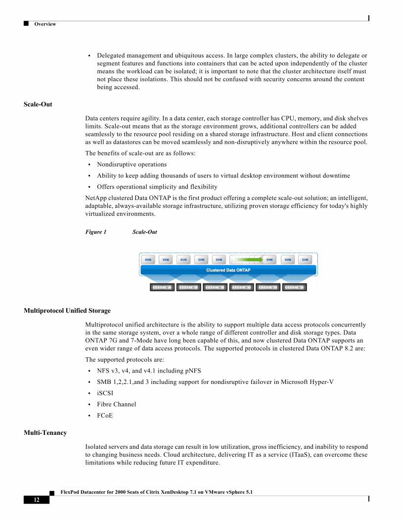
NetApp clustered Data ONTAP is the first product offering a complete scale-out solution; an intelligent, adaptable, always-available storage infrastructure, utilizing proven storage efficiency for today's highly virtualized environments.
Figure 1 Scale-Out
Multiprotocol Unified Storage
Multiprotocol unified architecture is the ability to support multiple data access protocols concurrently in the same storage system, over a whole range of different controller and disk storage types. Data ONTAP 7G and 7-Mode have long been capable of this, and now clustered Data ONTAP supports an even wider range of data access protocols. The supported protocols in clustered Data ONTAP 8.2 are:
The supported protocols are:
• NFS v3, v4, and v4.1 including pNFS
• SMB 1,2,2.1,and 3 including support for nondisruptive failover in Microsoft Hyper-V
• iSCSI
• Fibre Channel
• FCoE
Multi-Tenancy
Isolated servers and data storage can result in low utilization, gross inefficiency, and inability to respond to changing business needs. Cloud architecture, delivering IT as a service (ITaaS), can overcome these limitations while reducing future IT expenditure.
12FlexPod Datacenter for 2000 Seats of Citrix XenDesktop 7.1 on VMware vSphere 5.1
Overview
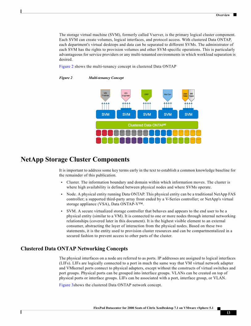
The storage virtual machine (SVM), formerly called Vserver, is the primary logical cluster component. Each SVM can create volumes, logical interfaces, and protocol access. With clustered Data ONTAP, each department's virtual desktops and data can be separated to different SVMs. The administrator of each SVM has the rights to provision volumes and other SVM-specific operations. This is particularly advantageous for service providers or any multi-tenanted environments in which workload separation is desired.
Figure 2 shows the multi-tenancy concept in clustered Data ONTAP
Figure 2 Multi-tenancy Concept
NetApp Storage Cluster Components
It is important to address some key terms early in the text to establish a common knowledge baseline for the remainder of this publication.
• Cluster. The information boundary and domain within which information moves. The cluster is where high availability is defined between physical nodes and where SVMs operate.
• Node. A physical entity running Data ONTAP. This physical entity can be a traditional NetApp FAS controller; a supported third-party array front ended by a V-Series controller; or NetApp's virtual storage appliance (VSA), Data ONTAP-V™.
• SVM. A secure virtualized storage controller that behaves and appears to the end user to be a physical entity (similar to a VM). It is connected to one or more nodes through internal networking relationships (covered later in this document). It is the highest visible element to an external consumer, abstracting the layer of interaction from the physical nodes. Based on these two statements, it is the entity used to provision cluster resources and can be compartmentalized in a secured fashion to prevent access to other parts of the cluster.
Clustered Data ONTAP Networking Concepts
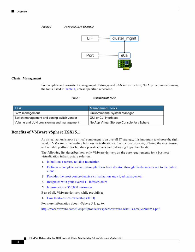
The physical interfaces on a node are referred to as ports. IP addresses are assigned to logical interfaces (LIFs). LIFs are logically connected to a port in much the same way that VM virtual network adapter and VMkernel ports connect to physical adapters, except without the constructs of virtual switches and port groups. Physical ports can be grouped into interface groups. VLANs can be created on top of physical ports or interface groups. LIFs can be associated with a port, interface group, or VLAN.
Figure 3shows the clustered Data ONTAP network concept.
13FlexPod Datacenter for 2000 Seats of Citrix XenDesktop 7.1 on VMware vSphere 5.1
Overview
Figure 3 Ports and LIFs Example
Cluster Management
For complete and consistent management of storage and SAN infrastructure, NetApp recommends using the tools listed in Table 1, unless specified otherwise.
Table 1 Management Tools
Benefits of VMware vSphere ESXi 5.1
As virtualization is now a critical component to an overall IT strategy, it is important to choose the right vendor. VMware is the leading business virtualization infrastructure provider, offering the most trusted and reliable platform for building private clouds and federating to public clouds.
The following list describes how only VMware delivers on the core requirements for a business virtualization infrastructure solution.
1. Is built on a robust, reliable foundation
2. Delivers a complete virtualization platform from desktop through the datacenter out to the public cloud
3. Provides the most comprehensive virtualization and cloud management
4. Integrates with your overall IT infrastructure
5. Is proven over 350,000 customers
Best of all, VMware delivers while providing:
6. Low total-cost-of-ownership (TCO)
For more information about vSphere 5.1, go to:
http://www.vmware.com/files/pdf/products/vsphere/vmware-what-is-new-vsphere51.pdf
Task Management Tools
SVM management OnCommand® System Manager
Switch management and zoning switch vendor GUI or CLI interfaces
Volume and LUN provisioning and management NetApp Virtual Storage Console for vSphere
14FlexPod Datacenter for 2000 Seats of Citrix XenDesktop 7.1 on VMware vSphere 5.1
Architecture
Benefits of Citrix XenDesktop 7
There are many reasons to consider a virtual desktop solution. An ever growing and diverse base of users, an expanding number of traditional desktops, an increase in security mandates and government regulations, and the introduction of Bring Your Own Device (BYOD) initiatives are factors that add to the cost and complexity of delivering and managing desktop and application services.
Citrix XenDesktop™ 7 transforms the delivery of Microsoft Windows apps and desktops into a secure, centrally managed service that users can access on any device, anywhere. The release focuses on delivering these benefits:
• Mobilizing Microsoft Windows application delivery, bringing thousands of corporate applications to mobile devices with a native-touch experience and high performance
• Reducing costs with simplified and centralized management and automated operations
• Securing data by centralizing information and effectively controlling access
Citrix XenDesktop 7 promotes mobility, allowing users to search for and subscribe to published resources, enabling a service delivery model that is cloud-ready.
The release follows a new unified FlexCast 2.0 architecture for provisioning all Windows apps and desktops either on hosted-shared RDS servers or VDI-based virtual machines. The new architecture combines simplified and integrated provisioning with personalization tools. Whether a customer is creating a system to deliver just apps or complete desktops, Citrix XenDesktop 7 leverages common policies and cohesive tools to govern infrastructure resources and access.
Architecture
Hardware Deployed
The architecture deployed is highly modular. While each customer's environment might vary in its exact configuration, when the reference architecture contained in this document is built, it can easily be scaled as requirements and demands change. This includes scaling both up (adding additional resources within a Cisco UCS Domain) and out (adding additional Cisco UCS Domains and NetApp FAS Storage arrays).
The 2000-user XenDesktop 7 solution includes Cisco networking, Cisco Unified Computing System and NetApp FAS storage, which fits into a single data center rack, including the access layer network switches.
This validated design document details the deployment of the 2000-user configurations for a mixed XenDesktop workload featuring the following software:
• Citrix XenDesktop 7.1 Pooled Hosted Virtual Desktops with PVS write cache on NFS storage
• Citrix XenDesktop 7.1 Shared Hosted Virtual Desktops with PVS write cache on NFS storage
• Citrix Provisioning Server 7.1
• Citrix User Profile Manager
• Citrix StoreFront 2.1
• Cisco Nexus 1000V Distributed Virtual Switch
• Cisco Virtual Machine Fabric Extender (VM-FEX)
• VMware vSphere ESXi 5.1 Hypervisor
• Microsoft Windows Server 2012 and Windows 7 32-bit virtual machine Operating Systems
15FlexPod Datacenter for 2000 Seats of Citrix XenDesktop 7.1 on VMware vSphere 5.1
Architecture
• Microsoft SQL Server 2012 SP1
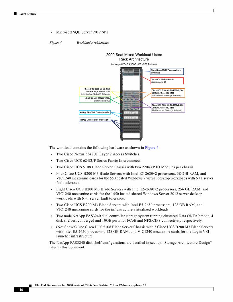
Figure 4 Workload Architecture
The workload contains the following hardware as shown in Figure 4:
• Two Cisco Nexus 5548UP Layer 2 Access Switches
• Two Cisco UCS 6248UP Series Fabric Interconnects
• Two Cisco UCS 5108 Blade Server Chassis with two 2204XP IO Modules per chassis
• Four Cisco UCS B200 M3 Blade Servers with Intel E5-2680v2 processors, 384GB RAM, and VIC1240 mezzanine cards for the 550 hosted Windows 7 virtual desktop workloads with N+1 server fault tolerance.
• Eight Cisco UCS B200 M3 Blade Servers with Intel E5-2680v2 processors, 256 GB RAM, and VIC1240 mezzanine cards for the 1450 hosted shared Windows Server 2012 server desktop workloads with N+1 server fault tolerance.
• Two Cisco UCS B200 M3 Blade Servers with Intel E5-2650 processors, 128 GB RAM, and VIC1240 mezzanine cards for the infrastructure virtualized workloads
• Two node NetApp FAS3240 dual controller storage system running clustered Data ONTAP mode, 4 disk shelves, converged and 10GE ports for FCoE and NFS/CIFS connectivity respectively.
• (Not Shown) One Cisco UCS 5108 Blade Server Chassis with 3 Cisco UCS B200 M3 Blade Servers with Intel E5-2650 processors, 128 GB RAM, and VIC1240 mezzanine cards for the Login VSI launcher infrastructure
The NetApp FAS3240 disk shelf configurations are detailed in section “Storage Architecture Design” later in this document.
16FlexPod Datacenter for 2000 Seats of Citrix XenDesktop 7.1 on VMware vSphere 5.1
Architecture
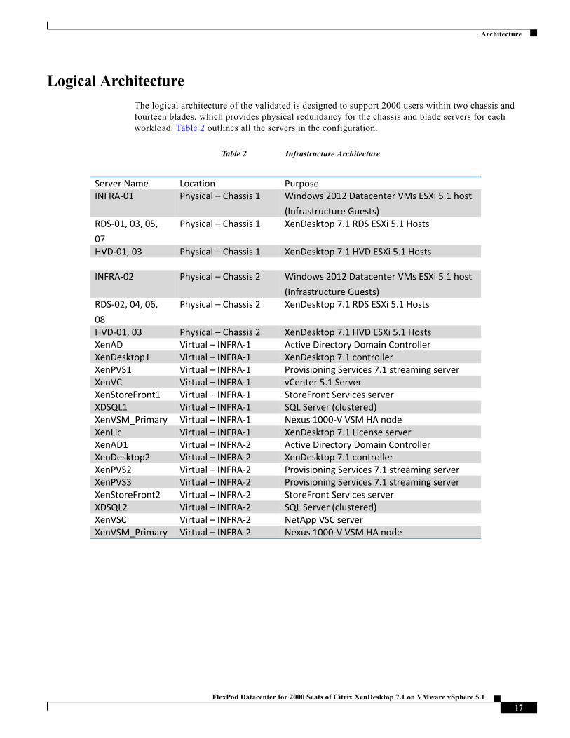
Logical Architecture
The logical architecture of the validated is designed to support 2000 users within two chassis and fourteen blades, which provides physical redundancy for the chassis and blade servers for each workload. Table 2 outlines all the servers in the configuration.
Table 2 Infrastructure Architecture
Server Name Location PurposeINFRA‐01 Physical – Chassis 1 Windows 2012 Datacenter VMs ESXi 5.1 host
(Infrastructure Guests)RDS‐01, 03, 05,
07
Physical – Chassis 1 XenDesktop 7.1 RDS ESXi 5.1 Hosts
HVD‐01, 03 Physical – Chassis 1 XenDesktop 7.1 HVD ESXi 5.1 Hosts
INFRA‐02 Physical – Chassis 2 Windows 2012 Datacenter VMs ESXi 5.1 host
(Infrastructure Guests)RDS‐02, 04, 06,
08
Physical – Chassis 2 XenDesktop 7.1 RDS ESXi 5.1 Hosts
HVD‐01, 03 Physical – Chassis 2 XenDesktop 7.1 HVD ESXi 5.1 HostsXenAD Virtual – INFRA‐1 Active Directory Domain ControllerXenDesktop1 Virtual – INFRA‐1 XenDesktop 7.1 controllerXenPVS1 Virtual – INFRA‐1 Provisioning Services 7.1 streaming serverXenVC Virtual – INFRA‐1 vCenter 5.1 ServerXenStoreFront1 Virtual – INFRA‐1 StoreFront Services serverXDSQL1 Virtual – INFRA‐1 SQL Server (clustered)XenVSM_Primary Virtual – INFRA‐1 Nexus 1000‐V VSM HA nodeXenLic Virtual – INFRA‐1 XenDesktop 7.1 License serverXenAD1 Virtual – INFRA‐2 Active Directory Domain ControllerXenDesktop2 Virtual – INFRA‐2 XenDesktop 7.1 controllerXenPVS2 Virtual – INFRA‐2 Provisioning Services 7.1 streaming serverXenPVS3 Virtual – INFRA‐2 Provisioning Services 7.1 streaming serverXenStoreFront2 Virtual – INFRA‐2 StoreFront Services serverXDSQL2 Virtual – INFRA‐2 SQL Server (clustered)XenVSC Virtual – INFRA‐2 NetApp VSC serverXenVSM_Primary Virtual – INFRA‐2 Nexus 1000‐V VSM HA node
17FlexPod Datacenter for 2000 Seats of Citrix XenDesktop 7.1 on VMware vSphere 5.1
Architecture
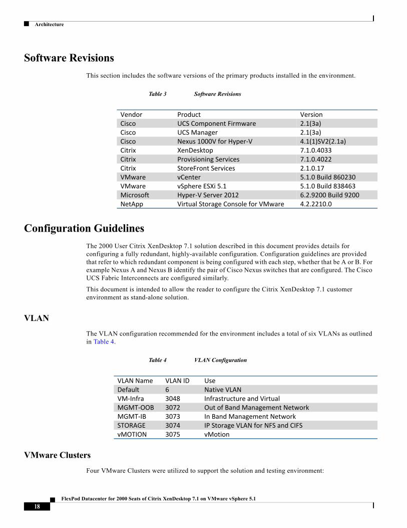
Software Revisions
This section includes the software versions of the primary products installed in the environment.
Table 3 Software Revisions
Configuration Guidelines
The 2000 User Citrix XenDesktop 7.1 solution described in this document provides details for configuring a fully redundant, highly-available configuration. Configuration guidelines are provided that refer to which redundant component is being configured with each step, whether that be A or B. For example Nexus A and Nexus B identify the pair of Cisco Nexus switches that are configured. The Cisco UCS Fabric Interconnects are configured similarly.
This document is intended to allow the reader to configure the Citrix XenDesktop 7.1 customer environment as stand-alone solution.
VLAN
The VLAN configuration recommended for the environment includes a total of six VLANs as outlined in Table 4.
Table 4 VLAN Configuration
VMware Clusters
Four VMware Clusters were utilized to support the solution and testing environment:
Vendor Product VersionCisco UCS Component Firmware 2.1(3a)Cisco UCS Manager 2.1(3a)Cisco Nexus 1000V for Hyper‐V 4.1(1)SV2(2.1a)Citrix XenDesktop 7.1.0.4033Citrix Provisioning Services 7.1.0.4022Citrix StoreFront Services 2.1.0.17VMware vCenter 5.1.0 Build 860230VMware vSphere ESXi 5.1 5.1.0 Build 838463Microsoft Hyper‐V Server 2012 6.2.9200 Build 9200NetApp Virtual Storage Console for VMware 4.2.2210.0
VLAN Name VLAN ID UseDefault 6 Native VLANVM‐Infra 3048 Infrastructure and VirtualMGMT‐OOB 3072 Out of Band Management NetworkMGMT‐IB 3073 In Band Management NetworkSTORAGE 3074 IP Storage VLAN for NFS and CIFSvMOTION 3075 vMotion
18FlexPod Datacenter for 2000 Seats of Citrix XenDesktop 7.1 on VMware vSphere 5.1
Infrastructure Components
• Infrastructure Cluster (vCenter, Active Directory, DNS, DHCP, SQL Clusters, XenDesktop Controllers, Provisioning Servers, and Cisco Nexus 1000V Virtual Switch Manager appliances, etc.)
• XenDesktop RDS Clusters (Windows Server 2012 hosted shared desktops)
• XenDesktop Hosted Virtual Desktop Cluster (Windows 7 SP1 32-bit pooled virtual desktops)
• Launcher Cluster (The Login Consultants Login VSI launcher infrastructure was hosted on the same Cisco UCS Domain sharing switching, but running on separate storage.)
Infrastructure ComponentsThis section describes the infrastructure components used in the solution outlined in this study.
Cisco Unified Computing System
Cisco Unified Computing System is a set of pre-integrated data center components that comprises blade servers, adapters, fabric interconnects, and extenders that are integrated under a common embedded management system. This approach results in far fewer system components and much better manageability, operational efficiencies, and flexibility than comparable data center platforms.
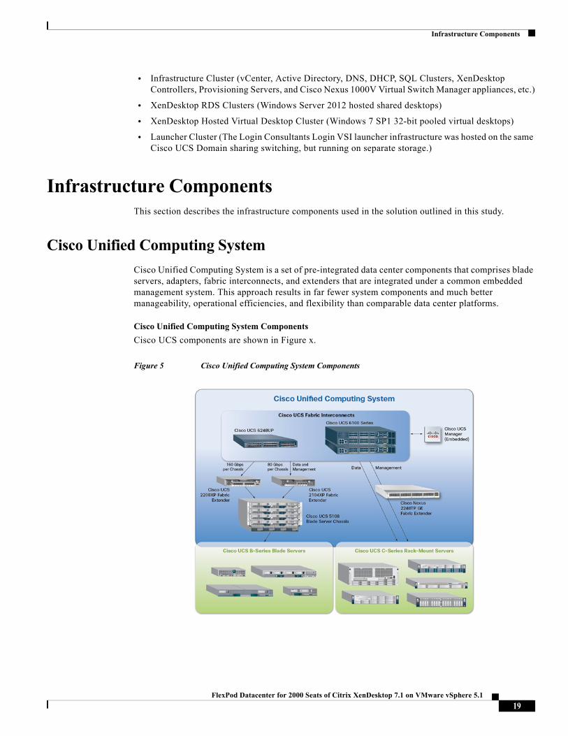
Cisco Unified Computing System Components
Cisco UCS components are shown in Figure x.
Figure 5 Cisco Unified Computing System Components
19FlexPod Datacenter for 2000 Seats of Citrix XenDesktop 7.1 on VMware vSphere 5.1

Infrastructure Components
Cisco Unified Computing System is designed to be programmable and self-integrating. A server's entire hardware stack, ranging from server firmware and settings to network profiles, is configured through model-based management. With Cisco virtual interface cards, even the number and type of I/O interfaces is programmed dynamically, making every server ready to power any workload at any time.
With model-based management, administrators manipulate a model of a desired system configuration, associate a model's service profile with hardware resources and the system configures itself to match the model. This automation speeds provisioning and workload migration with accurate and rapid scalability. The result is increased IT staff productivity, improved compliance, and reduced risk of failures due to inconsistent configurations.
Cisco Fabric Extender technology reduces the number of system components to purchase, configure, manage, and maintain by condensing three network layers into one. It eliminates both blade server and hypervisor-based switches by connecting fabric interconnect ports directly to individual blade servers and virtual machines. Virtual networks are now managed exactly as physical networks are, but with massive scalability. This represents a radical simplification over traditional systems, reducing capital and operating costs while increasing business agility, simplifying and speeding deployment, and improving performance.
Fabric Interconnect
Cisco UCS Fabric Interconnects create a unified network fabric throughout Cisco Unified Computing System. They provide uniform access to both networks and storage, eliminating the barriers to deploying a fully virtualized environment based on a flexible, programmable pool of resources.
Cisco Fabric Interconnects comprise a family of line-rate, low-latency, lossless 10-GE, Cisco Data Center Ethernet, and FCoE interconnect switches. Based on the same switching technology as the Cisco Nexus 5000 Series, Cisco UCS 6000 Series Fabric Interconnects provide the additional features and management capabilities that make them the central nervous system of Cisco Unified Computing System.
The Cisco UCS Manager software runs inside the Cisco UCS Fabric Interconnects. The Cisco UCS 6000 Series Fabric Interconnects expand the UCS networking portfolio and offer higher capacity, higher port density, and lower power consumption. These interconnects provide the management and communication backbone for the Cisco UCS B-Series Blades and Cisco UCS Blade Server Chassis.
All chassis and all blades that are attached to the Fabric Interconnects are part of a single, highly available management domain. By supporting unified fabric, the Cisco UCS 6200 Series provides the flexibility to support LAN and SAN connectivity for all blades within its domain right at configuration time. Typically deployed in redundant pairs, the Cisco UCS Fabric Interconnect provides uniform access to both networks and storage, facilitating a fully virtualized environment.
The Cisco UCS Fabric Interconnect family is currently comprised of the Cisco 6100 Series and Cisco 6200 Series of Fabric Interconnects.
Cisco UCS 6248UP 48-Port Fabric Interconnect
The Cisco UCS 6248UP 48-Port Fabric Interconnect is a 1 RU, 10-GE, Cisco Data Center Ethernet, FCoE interconnect providing more than 1Tbps throughput with low latency. It has 32 fixed ports of Fibre Channel, 10-GE, Cisco Data Center Ethernet, and FCoE SFP+ ports.
One expansion module slot can be up to sixteen additional ports of Fibre Channel, 10-GE, Cisco Data Center Ethernet, and FCoE SFP+.
Note Cisco UCS 6248UP 48-Port Fabric Interconnects were used in this study.
20FlexPod Datacenter for 2000 Seats of Citrix XenDesktop 7.1 on VMware vSphere 5.1
Infrastructure Components
Cisco UCS 2200 Series IO Module
The Cisco UCS 2100/2200 Series FEX multiplexes and forwards all traffic from blade servers in a chassis to a parent Cisco UCS Fabric Interconnect over from 10-Gbps unified fabric links. All traffic, even traffic between blades on the same chassis, or VMs on the same blade, is forwarded to the parent interconnect, where network profiles are managed efficiently and effectively by the Fabric Interconnect. At the core of the Cisco UCS Fabric Extender are ASIC processors developed by Cisco that multiplex all traffic.
Note Up to two fabric extenders can be placed in a blade chassis.
Cisco UCS 2104 has eight 10GBASE-KR connections to the blade chassis mid-plane, with one connection per fabric extender for each of the chassis' eight half slots. This gives each half-slot blade server access to each of two 10-Gbps unified fabric-based networks through SFP+ sockets for both throughput and redundancy. It has 4 ports connecting up the fabric interconnect.
Cisco UCS 2208 has thirty-two 10GBASE-KR connections to the blade chassis midplane, with one connection per fabric extender for each of the chassis' eight half slots. This gives each half-slot blade server access to each of two 4x10-Gbps unified fabric-based networks through SFP+ sockets for both throughput and redundancy. It has 8 ports connecting up the fabric interconnect.
Note Cisco UCS 2208 fabric extenders were utilized in this study.
Cisco UCS Chassis
The Cisco UCS 5108 Series Blade Server Chassis is a 6 RU blade chassis that will accept up to eight half-width Cisco UCS B-Series Blade Servers or up to four full-width Cisco UCS B-Series Blade Servers, or a combination of the two. The UCS 5108 Series Blade Server Chassis can accept four redundant power supplies with automatic load-sharing and failover and two Cisco UCS (either 2100 or 2200 series ) Fabric Extenders. The chassis is managed by Cisco UCS Chassis Management Controllers, which are mounted in the Cisco UCS Fabric Extenders and work in conjunction with the Cisco UCS Manager to control the chassis and its components.
A single Cisco UCS managed domain can theoretically scale to up to 40 individual chassis and 320 blade servers. At this time Cisco supports up to 20 individual chassis and 160 blade servers.
Basing the I/O infrastructure on a 10-Gbps unified network fabric allows the Cisco UCS to have a streamlined chassis with a simple yet comprehensive set of I/O options. The result is a chassis that has only five basic components:
• The physical chassis with passive midplane and active environmental monitoring circuitry
• Four power supply bays with power entry in the rear, and hot-swappable power supply units accessible from the front panel
• Eight hot-swappable fan trays, each with two fans
• Two fabric extender slots accessible from the back panel
• Eight blade server slots accessible from the front panel
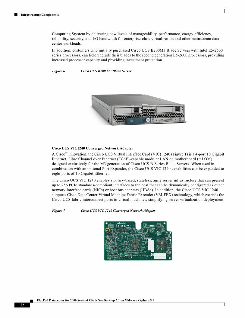
Cisco UCS B200 M3 Blade Server
Cisco UCS B200 M3 Blade Server is a third generation half-slot, two-socket blade server. The Cisco UCS B200 M3 Blade Server harnesses the power of the latest Intel® Xeon® processor E5-2600 v2 product family, with up to 768 GB of RAM (using 32GB DIMMs), two optional SAS/SATA/SSD disk drives, and up to dual 4x 10 Gigabit Ethernet throughput, utilizing our VIC 1240 LAN on motherboard (LOM) design. The Cisco UCS B200 M3 Blade Server further extends the capabilities of Cisco Unified
21FlexPod Datacenter for 2000 Seats of Citrix XenDesktop 7.1 on VMware vSphere 5.1
Infrastructure Components
Computing Stystem by delivering new levels of manageability, performance, energy efficiency, reliability, security, and I/O bandwidth for enterprise-class virtualization and other mainstream data center workloads.
In addition, customers who initially purchased Cisco UCS B200M3 Blade Servers with Intel E5-2600 series processors, can field upgrade their blades to the second generation E5-2600 processors, providing increased processor capacity and providing investment protection
Figure 6 Cisco UCS B200 M3 Blade Server
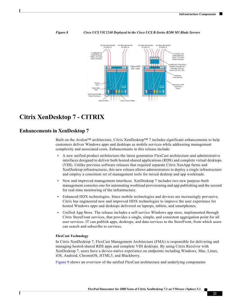
Cisco UCS VIC1240 Converged Network Adapter
A Cisco® innovation, the Cisco UCS Virtual Interface Card (VIC) 1240 (Figure 1) is a 4-port 10 Gigabit Ethernet, Fibre Channel over Ethernet (FCoE)-capable modular LAN on motherboard (mLOM) designed exclusively for the M3 generation of Cisco UCS B-Series Blade Servers. When used in combination with an optional Port Expander, the Cisco UCS VIC 1240 capabilities can be expanded to eight ports of 10 Gigabit Ethernet.
The Cisco UCS VIC 1240 enables a policy-based, stateless, agile server infrastructure that can present up to 256 PCIe standards-compliant interfaces to the host that can be dynamically configured as either network interface cards (NICs) or host bus adapters (HBAs). In addition, the Cisco UCS VIC 1240 supports Cisco Data Center Virtual Machine Fabric Extender (VM-FEX) technology, which extends the Cisco UCS fabric interconnect ports to virtual machines, simplifying server virtualization deployment.
Figure 7 Cisco UCS VIC 1240 Converged Network Adapter
22FlexPod Datacenter for 2000 Seats of Citrix XenDesktop 7.1 on VMware vSphere 5.1
Infrastructure Components
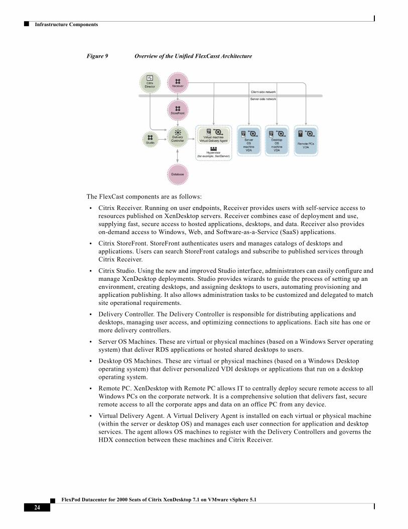
Figure 8 Cisco UCS VIC1240 Deployed in the Cisco UCS B-Series B200 M3 Blade Servers
Citrix XenDesktop 7 - CITRIX
Enhancements in XenDesktop 7
Built on the Avalon™ architecture, Citrix XenDesktop™ 7 includes significant enhancements to help customers deliver Windows apps and desktops as mobile services while addressing management complexity and associated costs. Enhancements in this release include:
• A new unified product architecture-the latest generation FlexCast architecture-and administrative interfaces designed to deliver both hosted-shared applications (RDS) and complete virtual desktops (VDI). Unlike previous software releases that required separate Citrix XenApp farms and XenDesktop infrastructures, this new release allows administrators to deploy a single infrastructure and employ a consistent set of management tools for mixed desktop and app workloads.
• New and improved management interfaces. XenDesktop 7 includes two new purpose-built management consoles-one for automating workload provisioning and app publishing and the second for real-time monitoring of the infrastructure.
• Enhanced HDX technologies. Since mobile technologies and devices are increasingly pervasive, Citrix has engineered new and improved HDX technologies to improve the user experience for hosted Windows apps and desktops delivered on laptops, tablets, and smartphones.
• Unified App Store. The release includes a self-service Windows app store, implemented through Citrix StoreFront services, that provides a single, simple, and consistent aggregation point for all user services. IT can publish apps, desktops, and data services to the StoreFront, from which users can search and subscribe to services.
FlexCast Technology
In Citrix XenDesktop 7, FlexCast Management Architecture (FMA) is responsible for delivering and managing hosted-shared RDS apps and complete VDI desktops. By using Citrix Receiver with XenDesktop 7, users have a device-native experience on endpoints including Windows, Mac, Linux, iOS, Android, ChromeOS, HTML5, and Blackberry.
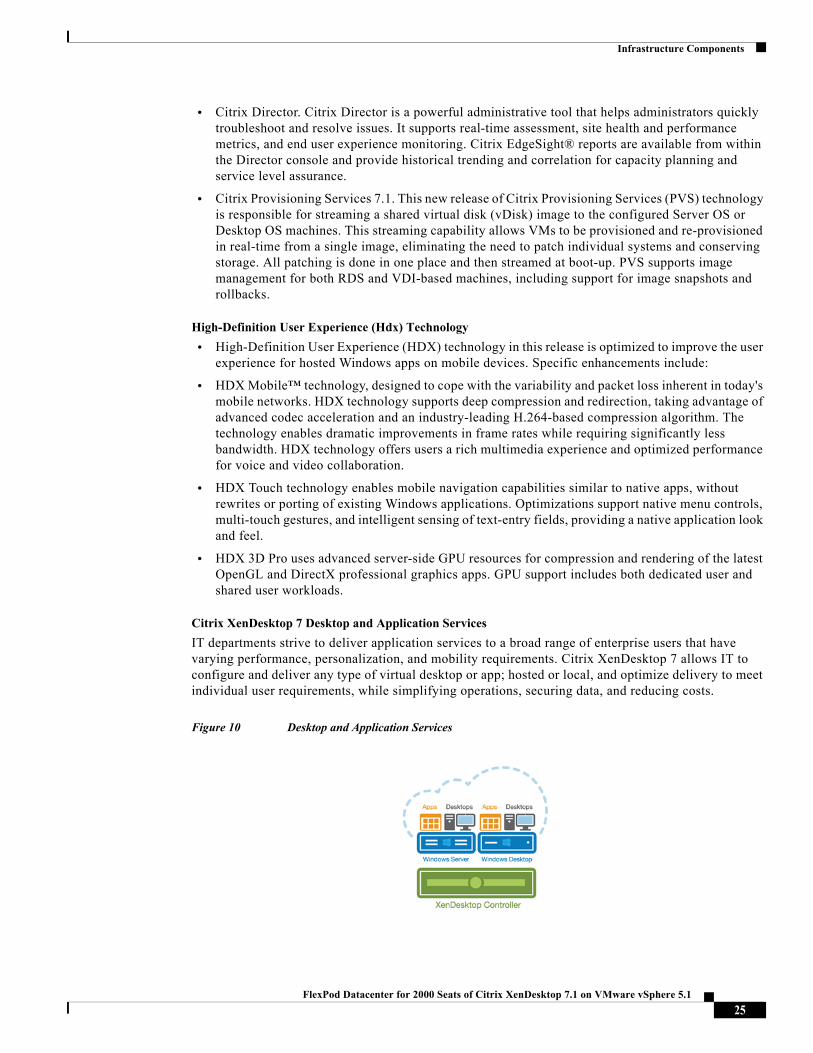
Figure 9 shows an overview of the unified FlexCast architecture and underlying components
23FlexPod Datacenter for 2000 Seats of Citrix XenDesktop 7.1 on VMware vSphere 5.1
Infrastructure Components
Figure 9 Overview of the Unified FlexCasst Architecture
The FlexCast components are as follows:
• Citrix Receiver. Running on user endpoints, Receiver provides users with self-service access to resources published on XenDesktop servers. Receiver combines ease of deployment and use, supplying fast, secure access to hosted applications, desktops, and data. Receiver also provides on-demand access to Windows, Web, and Software-as-a-Service (SaaS) applications.
• Citrix StoreFront. StoreFront authenticates users and manages catalogs of desktops and applications. Users can search StoreFront catalogs and subscribe to published services through Citrix Receiver.
• Citrix Studio. Using the new and improved Studio interface, administrators can easily configure and manage XenDesktop deployments. Studio provides wizards to guide the process of setting up an environment, creating desktops, and assigning desktops to users, automating provisioning and application publishing. It also allows administration tasks to be customized and delegated to match site operational requirements.
• Delivery Controller. The Delivery Controller is responsible for distributing applications and desktops, managing user access, and optimizing connections to applications. Each site has one or more delivery controllers.
• Server OS Machines. These are virtual or physical machines (based on a Windows Server operating system) that deliver RDS applications or hosted shared desktops to users.
• Desktop OS Machines. These are virtual or physical machines (based on a Windows Desktop operating system) that deliver personalized VDI desktops or applications that run on a desktop operating system.
• Remote PC. XenDesktop with Remote PC allows IT to centrally deploy secure remote access to all Windows PCs on the corporate network. It is a comprehensive solution that delivers fast, secure remote access to all the corporate apps and data on an office PC from any device.
• Virtual Delivery Agent. A Virtual Delivery Agent is installed on each virtual or physical machine (within the server or desktop OS) and manages each user connection for application and desktop services. The agent allows OS machines to register with the Delivery Controllers and governs the HDX connection between these machines and Citrix Receiver.
24FlexPod Datacenter for 2000 Seats of Citrix XenDesktop 7.1 on VMware vSphere 5.1
Infrastructure Components
• Citrix Director. Citrix Director is a powerful administrative tool that helps administrators quickly troubleshoot and resolve issues. It supports real-time assessment, site health and performance metrics, and end user experience monitoring. Citrix EdgeSight® reports are available from within the Director console and provide historical trending and correlation for capacity planning and service level assurance.
• Citrix Provisioning Services 7.1. This new release of Citrix Provisioning Services (PVS) technology is responsible for streaming a shared virtual disk (vDisk) image to the configured Server OS or Desktop OS machines. This streaming capability allows VMs to be provisioned and re-provisioned in real-time from a single image, eliminating the need to patch individual systems and conserving storage. All patching is done in one place and then streamed at boot-up. PVS supports image management for both RDS and VDI-based machines, including support for image snapshots and rollbacks.
High-Definition User Experience (Hdx) Technology
• High-Definition User Experience (HDX) technology in this release is optimized to improve the user experience for hosted Windows apps on mobile devices. Specific enhancements include:
• HDX Mobile™ technology, designed to cope with the variability and packet loss inherent in today's mobile networks. HDX technology supports deep compression and redirection, taking advantage of advanced codec acceleration and an industry-leading H.264-based compression algorithm. The technology enables dramatic improvements in frame rates while requiring significantly less bandwidth. HDX technology offers users a rich multimedia experience and optimized performance for voice and video collaboration.
• HDX Touch technology enables mobile navigation capabilities similar to native apps, without rewrites or porting of existing Windows applications. Optimizations support native menu controls, multi-touch gestures, and intelligent sensing of text-entry fields, providing a native application look and feel.
• HDX 3D Pro uses advanced server-side GPU resources for compression and rendering of the latest OpenGL and DirectX professional graphics apps. GPU support includes both dedicated user and shared user workloads.
Citrix XenDesktop 7 Desktop and Application Services
IT departments strive to deliver application services to a broad range of enterprise users that have varying performance, personalization, and mobility requirements. Citrix XenDesktop 7 allows IT to configure and deliver any type of virtual desktop or app; hosted or local, and optimize delivery to meet individual user requirements, while simplifying operations, securing data, and reducing costs.
Figure 10 Desktop and Application Services
25FlexPod Datacenter for 2000 Seats of Citrix XenDesktop 7.1 on VMware vSphere 5.1
Infrastructure Components
With previous product releases, administrators had to deploy separate XenApp farms and XenDesktop sites to support both hosted shared RDS and VDI desktops. As shown above, the new XenDesktop 7 release allows administrators to create a single infrastructure that supports multiple modes of service delivery, including:
• Application Virtualization and Hosting (RDS). Applications are installed on or streamed to Windows servers in the data center and remotely displayed to users' desktops and devices.
• Hosted Shared Desktops (RDS). Multiple user sessions share a single, locked-down Windows Server environment running in the datacenter and accessing a core set of apps. This model of service delivery is ideal for task workers using low intensity applications, and enables more desktops per host compared to VDI.
• Pooled VDI Desktops. This approach leverages a single desktop OS image to create multiple thinly provisioned or streamed desktops. Optionally, desktops can be configured with a Personal vDisk to maintain user application, profile and data differences that are not part of the base image. This approach replaces the need for dedicated desktops, and is generally deployed to address the desktop needs of knowledge workers that run more intensive application workloads.
• VM Hosted Apps (16 bit, 32 bit, or 64 bit Windows apps). Applications are hosted on virtual desktops running Windows 7, XP, or Vista and then remotely displayed to users' physical or virtual desktops and devices.
This CVD focuses on delivering a mixed workload consisting of hosted shared desktops (HSD or RDS) and hosted virtual desktops (HVD or VDI).
Citrix Provisioning Services
One significant advantage to service delivery through RDS and VDI is how these technologies simplify desktop administration and management. Citrix Provisioning Services (PVS) takes the approach of streaming a single shared virtual disk (vDisk) image rather than provisioning and distributing multiple OS image copies across multiple virtual machines. One advantage of this approach is that it constrains the number of disk images that must be managed, even as the number of desktops grows, ensuring image consistency. At the same time, using a single shared image (rather than hundreds or thousands of desktop images) significantly reduces the required storage footprint and dramatically simplifies image management.
Since there is a single master image, patch management is simple and reliable. All patching is done on the master image, which is then streamed as needed. When an updated image is ready for production, the administrator simply reboots to deploy the new image. Rolling back to a previous image is done in the same manner. Local hard disk drives in user systems can be used for runtime data caching or, in some scenarios, removed entirely, lowering power usage, system failure rates, and security risks.
After installing and configuring PVS components, a vDisk is created from a device's hard drive by taking a snapshot of the OS and application image, and then storing that image as a vDisk file on the network. vDisks can exist on a Provisioning Server, file share, or in larger deployments (as in this CVD), on a storage system with which the Provisioning Server can communicate (through iSCSI, SAN, NAS, and CIFS). vDisks can be assigned to a single target device in Private Image Mode, or to multiple target devices in Standard Image Mode.
When a user device boots, the appropriate vDisk is located based on the boot configuration and mounted on the Provisioning Server. The software on that vDisk is then streamed to the target device and appears like a regular hard drive to the system. Instead of pulling all the vDisk contents down to the target device (as is done with some imaging deployment solutions), the data is brought across the network in real time, as needed. This greatly improves the overall user experience since it minimizes desktop startup time.
26FlexPod Datacenter for 2000 Seats of Citrix XenDesktop 7.1 on VMware vSphere 5.1
Infrastructure Components
This release of PVS extends built-in administrator roles to support delegated administration based on groups that already exist within the network (Windows or Active Directory Groups). All group members share the same administrative privileges within a farm. An administrator may have multiple roles if they belong to more than one group.
NetApp FAS3200-Series
The FAS3200-series delivers leading performance and scale for SAN and NAS workloads in the midrange storage market. The new FAS3200 systems offer up to 80% more performance and 100% more capacity than previous systems, raising the bar for value in the midrange.
Benefits
• .Designed for agility, providing intelligent management, immortal operations, and infinite scaling
• .Flash optimized with more choices and flexibility for application acceleration
• .Cluster enabled to offer nondisruptive operations, eliminating planned and unplanned downtime
• .Industry-leading storage efficiency lowers storage costs on day one and over time
Target Customers and Environment
• Medium to large enterprises
• Regional data centers, replicated sites, and ?departmental systems
• Midsize businesses that need full-featured and efficient storage with advanced availability and performance
• FAS3200-series is an ideal solution for high-capacity environments, server and desktop virtualization, Windows storage consolidation, data protection, and disaster recovery for midsized businesses and distributed enterprise.
The FAS3200-series continues the tradition of NetApp price/performance leadership in the midrange family while introducing new features and capabilities needed by enterprises making long-term storage investments with today's budget. Key FAS/V3200 innovations include an I/O expansion module (IOXM) that provides configuration flexibility for enabling HA configurations in either 3U or 6U footprints, with the 6U configuration offering 50% more slot density than that of previous-generation FAS3100 systems. In addition to better performance and slot density, FAS/V3200 also offers reliability, availability, serviceability, and manageability (RASM) with the integrated service processor (SP), the next generation of remote management in the NetApp storage family. Key FAS3200-series features include:
• Higher performance versus that of the FAS/V3100 series
• Two PCIe v2.0 (Gen 2) PCIe slots in the controller
• I/O expansion module (IOXM) that provides 50% more expansion slots than the FAS3100
• Onboard SAS ports for DS2246, DS4243, DS4246, and DS4486 shelves or tape connectivity
• Integrated SP, next-generation RLM and BMC, which increase FAS/V3200 RASM
27FlexPod Datacenter for 2000 Seats of Citrix XenDesktop 7.1 on VMware vSphere 5.1
Infrastructure Components
NetApp FAS3240 Clustered Data ONTAP Used in Testing
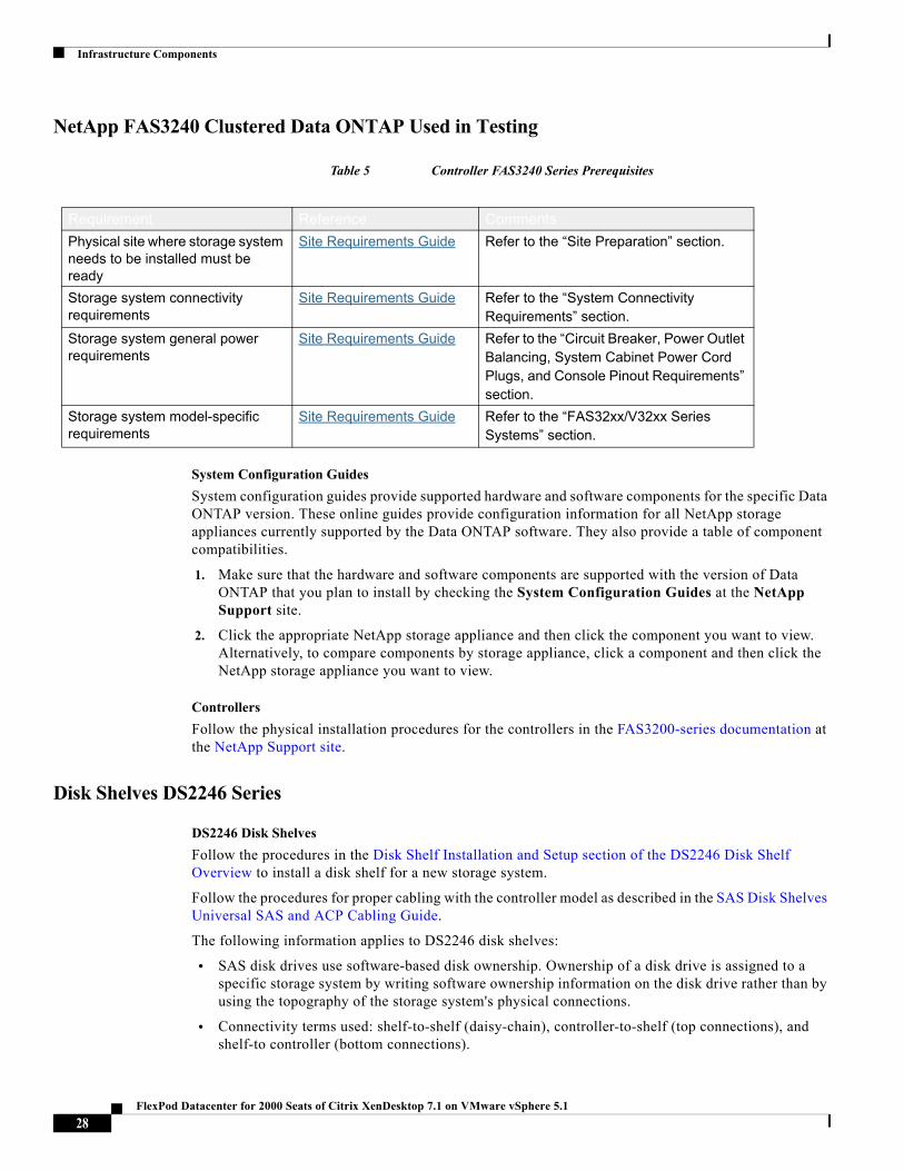
Table 5 Controller FAS3240 Series Prerequisites
System Configuration Guides
System configuration guides provide supported hardware and software components for the specific Data ONTAP version. These online guides provide configuration information for all NetApp storage appliances currently supported by the Data ONTAP software. They also provide a table of component compatibilities.
1. Make sure that the hardware and software components are supported with the version of Data ONTAP that you plan to install by checking the System Configuration Guides at the NetApp Support site.
2. Click the appropriate NetApp storage appliance and then click the component you want to view. Alternatively, to compare components by storage appliance, click a component and then click the NetApp storage appliance you want to view.
Controllers
Follow the physical installation procedures for the controllers in the FAS3200-series documentation at the NetApp Support site.
Disk Shelves DS2246 Series
DS2246 Disk Shelves
Follow the procedures in the Disk Shelf Installation and Setup section of the DS2246 Disk Shelf Overview to install a disk shelf for a new storage system.
Follow the procedures for proper cabling with the controller model as described in the SAS Disk Shelves Universal SAS and ACP Cabling Guide.
The following information applies to DS2246 disk shelves:
• SAS disk drives use software-based disk ownership. Ownership of a disk drive is assigned to a specific storage system by writing software ownership information on the disk drive rather than by using the topography of the storage system's physical connections.
• Connectivity terms used: shelf-to-shelf (daisy-chain), controller-to-shelf (top connections), and shelf-to controller (bottom connections).
Requirement Reference Comments
Physical site where storage system needs to be installed must be ready
Site Requirements Guide Refer to the “Site Preparation” section.
Storage system connectivity requirements
Site Requirements Guide Refer to the “System Connectivity Requirements” section.
Storage system general power requirements
Site Requirements Guide Refer to the “Circuit Breaker, Power Outlet Balancing, System Cabinet Power Cord Plugs, and Console Pinout Requirements” section.
Storage system model-specific requirements
Site Requirements Guide Refer to the “FAS32xx/V32xx Series Systems” section.
28FlexPod Datacenter for 2000 Seats of Citrix XenDesktop 7.1 on VMware vSphere 5.1
Infrastructure Components
• Unique disk shelf IDs must be set per storage system (a number from 0 through 98).
• Disk shelf power must be turned on to change the digital display shelf ID. The digital display is on the front of the disk shelf.
• Disk shelves must be power-cycled after the shelf ID is changed for it to take effect.
• Changing the shelf ID on a disk shelf that is part of an existing storage system running Data ONTAP requires that you wait at least 30 seconds before turning the power back on so that Data ONTAP can properly delete the old disk shelf address and update the copy of the new disk shelf address.
• Changing the shelf ID on a disk shelf that is part of a new storage system installation (the disk shelf is not yet running Data ONTAP) requires no wait; you can immediately power-cycle the disk shelf.
VMware ESXi 5.1
VMware vSphere® virtualizes and aggregates the underlying physical hardware resources across multiple systems and provides pools of virtual resources to the data center.
vSphere is a "bare-metal" hypervisor, meaning it installs directly on top of the physical server and partitions it into multiple virtual machines that can run simultaneously, sharing the physical resources of the underlying server. vSphere delivers industry-leading performance and scalability while setting a new bar for reliability, security and hypervisor management efficiency.
In the vSphere 5.1 release, VMware has added several significant enhancements to ESXi:
• NEW Improved Security - There is no longer a dependency on a shared root account when working from the ESXi Shell. Local users assigned administrative privileges automatically get full shell access. With full shell access local users no longer need to "su" to root in order to run privileged commands.
• NEW Improved Logging and Auditing - In vSphere 5.1 all host activity, from both the Shell and the Direct Console User Interface (DCUI), are now logged under the account of the logged in user. This ensures user accountability, making it easy to monitor and audit activity on the host.
• NEW Enhanced SNMPv3 Support - VSphere 5.1 adds support for SNMP v.3 to include both SNMP authentication and SSL encryption.
• NEW Enhanced vMotion - vSphere 5.1 provide a new level of ease and flexibility for live virtual machine migrations. vSphere 5.1 now allows combining vMotion and Storage vMotion into one operation. The combined migration copies both the virtual machine memory and its disk over the network to the destination host. In smaller environments the ability to simultaneously migrate both memory and storage allows virtual machines to be migrated between hosts that do not have shared storage. In larger environments this capability allows virtual machines to be migrated between clusters that do not have a common set of datastores.
• NEW vShield Endpoint Bundling - Now included in vSphere 5.1, vShield Endpoint offloads antivirus and anti-malware agent processing inside guest virtual machines to a dedicated secure virtual appliance delivered by VMware partners.
• NEW Virtual Hardware - VSphere 5.1 introduces a new generation of virtual hardware with virtual machine hardware version 9, which includes the following new features:
– 64-way virtual SMP. vSphere 5.1 supports virtual machines with up to 64 virtual CPUs, which lets you run larger CPU-intensive workloads on the VMware vSphere platform.
– 1TB virtual machine RAM. You can assign up to 1TB of RAM to VSphere 5.1 virtual machines.
– Hardware accelerated 3D graphics support for Windows Aero. vSphere 5.1 supports 3D graphics to run Windows Aero and Basic 3D applications in virtual machines.
29FlexPod Datacenter for 2000 Seats of Citrix XenDesktop 7.1 on VMware vSphere 5.1
Infrastructure Components
– Guest OS Storage Reclamation. With Guest OS Storage Reclamation, when files are removed from inside the guest OS the size of the VMDK file can be reduced and the de-allocated storage space returned to the storage array's free pool. Guest OS Storage Reclamation utilizes a new SE Sparse VMDK format available with Horizon View.
– Improved CPU virtualization. In vSphere 5.1 the vSphere host is better able to virtualize the physical CPU and thus expose more information about the CPU architecture to the virtual machine. vSphere 5.1 also adds the ability to exposes additional low-level CPU counters to the guest OS. Exposing the low-level CPU counter information allows for improved debugging, tuning and troubleshooting of operating systems and applications running inside the virtual machine.
Modular Virtual Desktop Infrastructure Technical Overview
Modular Architecture
Today's IT departments are facing a rapidly-evolving workplace environment. The workforce is becoming increasingly diverse and geographically distributed and includes offshore contractors, distributed call center operations, knowledge and task workers, partners, consultants, and executives connecting from locations around the globe at all times.
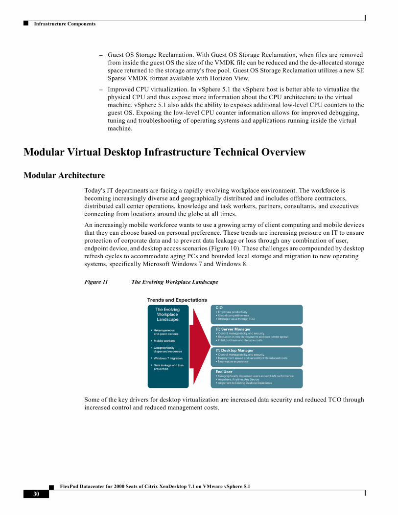
An increasingly mobile workforce wants to use a growing array of client computing and mobile devices that they can choose based on personal preference. These trends are increasing pressure on IT to ensure protection of corporate data and to prevent data leakage or loss through any combination of user, endpoint device, and desktop access scenarios (Figure 10). These challenges are compounded by desktop refresh cycles to accommodate aging PCs and bounded local storage and migration to new operating systems, specifically Microsoft Windows 7 and Windows 8.
Figure 11 The Evolving Workplace Landscape
Some of the key drivers for desktop virtualization are increased data security and reduced TCO through increased control and reduced management costs.
30FlexPod Datacenter for 2000 Seats of Citrix XenDesktop 7.1 on VMware vSphere 5.1
Infrastructure Components
Cisco Data Center Infrastructure for Desktop Virtualization
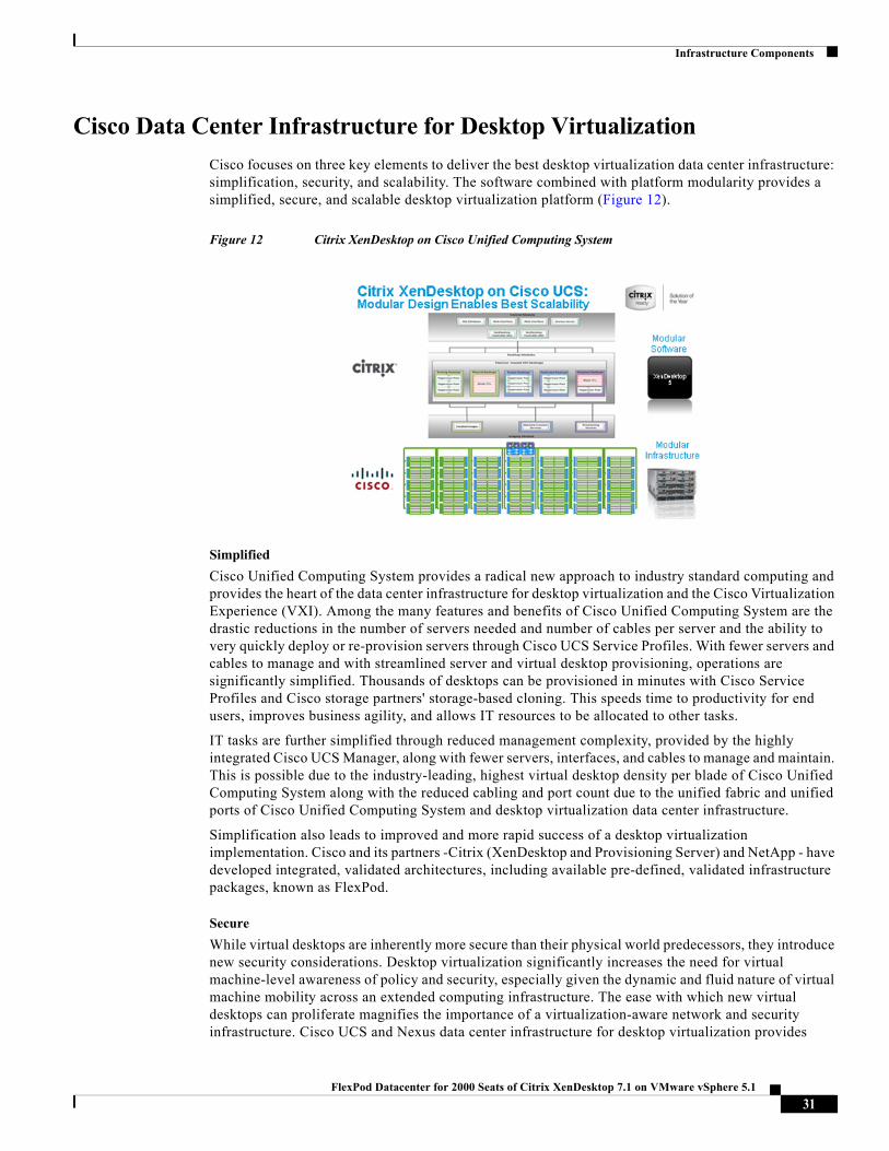
Cisco focuses on three key elements to deliver the best desktop virtualization data center infrastructure: simplification, security, and scalability. The software combined with platform modularity provides a simplified, secure, and scalable desktop virtualization platform (Figure 12).
Figure 12 Citrix XenDesktop on Cisco Unified Computing System
Simplified
Cisco Unified Computing System provides a radical new approach to industry standard computing and provides the heart of the data center infrastructure for desktop virtualization and the Cisco Virtualization Experience (VXI). Among the many features and benefits of Cisco Unified Computing System are the drastic reductions in the number of servers needed and number of cables per server and the ability to very quickly deploy or re-provision servers through Cisco UCS Service Profiles. With fewer servers and cables to manage and with streamlined server and virtual desktop provisioning, operations are significantly simplified. Thousands of desktops can be provisioned in minutes with Cisco Service Profiles and Cisco storage partners' storage-based cloning. This speeds time to productivity for end users, improves business agility, and allows IT resources to be allocated to other tasks.
IT tasks are further simplified through reduced management complexity, provided by the highly integrated Cisco UCS Manager, along with fewer servers, interfaces, and cables to manage and maintain. This is possible due to the industry-leading, highest virtual desktop density per blade of Cisco Unified Computing System along with the reduced cabling and port count due to the unified fabric and unified ports of Cisco Unified Computing System and desktop virtualization data center infrastructure.
Simplification also leads to improved and more rapid success of a desktop virtualization implementation. Cisco and its partners -Citrix (XenDesktop and Provisioning Server) and NetApp - have developed integrated, validated architectures, including available pre-defined, validated infrastructure packages, known as FlexPod.
Secure
While virtual desktops are inherently more secure than their physical world predecessors, they introduce new security considerations. Desktop virtualization significantly increases the need for virtual machine-level awareness of policy and security, especially given the dynamic and fluid nature of virtual machine mobility across an extended computing infrastructure. The ease with which new virtual desktops can proliferate magnifies the importance of a virtualization-aware network and security infrastructure. Cisco UCS and Nexus data center infrastructure for desktop virtualization provides
31FlexPod Datacenter for 2000 Seats of Citrix XenDesktop 7.1 on VMware vSphere 5.1
Infrastructure Components
stronger data center, network, and desktop security with comprehensive security from the desktop to the hypervisor. Security is enhanced with segmentation of virtual desktops, virtual machine-aware policies and administration, and network security across the LAN and WAN infrastructure.
Scalable
Growth of a desktop virtualization solution is all but inevitable and it is critical to have a solution that can scale predictably with that growth. The Cisco solution supports more virtual desktops per server and additional servers scale with near linear performance. Cisco data center infrastructure provides a flexible platform for growth and improves business agility. Cisco UCS Service Profiles allow for on-demand desktop provisioning, making it easy to deploy dozens or thousands of additional desktops.
Each additional Cisco UCS bladevserver provides near linear performance and utilizes Cisco's dense memory servers and unified fabric to avoid desktop virtualization bottlenecks. The high performance, low latency network supports high volumes of virtual desktop traffic, including high resolution video and communications.
Cisco UCS and Nexus data center infrastructure is an ideal platform for growth, with transparent scaling of server, network, and storage resources to support desktop virtualization.
Savings and Success
As demonstrated above, the simplified, secure, scalable Cisco data center infrastructure solution for desktop virtualization will save time and cost. There will be faster payback, better ROI, and lower TCO with the industry's highest virtual desktop density per server, meaning there will be fewer servers needed, reducing both capital expenditures (CapEx) and operating expenditures (OpEx). There will also be much lower network infrastructure costs, with fewer cables per server and fewer ports required, through the Cisco UCS architecture and unified fabric.
The simplified deployment of Cisco Unified Computing System for desktop virtualization speeds up time to productivity and enhances business agility. IT staff and end users are more productive more quickly and the business can react to new opportunities by simply deploying virtual desktops whenever and wherever they are needed. The high performance Cisco systems and network deliver a near-native end-user experience, allowing users to be productive anytime, anywhere.
Cisco Services
Cisco offers assistance for customers in the analysis, planning, implementation, and support phases of the VDI lifecycle. These services are provided by the Cisco Advanced Services group. Some examples of Cisco services include:
• Cisco VXI Unified Solution Support
• Cisco VXI Desktop Virtualization Strategy Service
• Cisco VXI Desktop Virtualization Planning and Design Service
The Solution: A Unified, Pre-Tested and Validated Infrastructure
To meet the challenges of designing and implementing a modular desktop infrastructure, Cisco, Citrix, NetApp and Microsoft have collaborated to create the data center solution for virtual desktops outlined in this document.
Key elements of the solution include:
• A shared infrastructure that can scale easily
• A shared infrastructure that can accommodate a variety of virtual desktop workloads
32FlexPod Datacenter for 2000 Seats of Citrix XenDesktop 7.1 on VMware vSphere 5.1
Infrastructure Components
Cisco Networking Infrastructure
This section describes the Cisco networking infrastructure components used in the configuration.
Cisco Nexus 5548 Switch
The Cisco Nexus 5548 Switch is a 1RU, 10 Gigabit Ethernet, FCoE access-layer switch built to provide more than 500 Gbps throughput with very low latency. It has 20 fixed 10 Gigabit Ethernet and FCoE ports that accept modules and cables meeting the Small Form-Factor Pluggable Plus (SFP+) form factor. One expansion module slot can be configured to support up to six additional 10 Gigabit Ethernet and FCoE ports, up to eight FC ports, or a combination of both. The switch has a single serial console port and a single out-of-band 10/100/1000-Mbps Ethernet management port. Two N+1 redundant, hot-pluggable power supplies and five N+1 redundant, hot-pluggable fan modules provide highly reliable front-to-back cooling.
Figure 13 Cisco Nexus 5548UP Unified Port Switch
Cisco Nexus 5500 Series Feature Highlights
The switch family's rich feature set makes the series ideal for rack-level, access-layer applications. It protects investments in data center racks with standards-based Ethernet and FCoE features that allow IT departments to consolidate networks based on their own requirements and timing.
• The combination of high port density, wire-speed performance, and extremely low latency makes the switch an ideal product to meet the growing demand for 10 Gigabit Ethernet at the rack level. The switch family has sufficient port density to support single or multiple racks fully populated with blade and rack-mount servers.
• Built for today's data centers, the switches are designed just like the servers they support. Ports and power connections are at the rear, closer to server ports, helping keep cable lengths as short and efficient as possible. Hot-swappable power and cooling modules can be accessed from the front panel, where status lights offer an at-a-glance view of switch operation. Front-to-back cooling is consistent with server designs, supporting efficient data center hot-aisle and cold-aisle designs. Serviceability is enhanced with all customer replaceable units accessible from the front panel. The use of SFP+ ports offers increased flexibility to use a range of interconnect solutions, including copper for short runs and fibre for long runs.
• FCoE and IEEE data center bridging features support I/O consolidation, ease management of multiple traffic flows, and optimize performance. Although implementing SAN consolidation requires only the lossless fabric provided by the Ethernet pause mechanism, the Cisco Nexus 5500 Series switches provide additional features that create an even more easily managed, high-performance, unified network fabric.
Features and Benefits
Specific features and benefits provided by the Cisco Nexus 5500 Series follow.
10GB Ethernet, FCoE, and Unified Fabric Features
33FlexPod Datacenter for 2000 Seats of Citrix XenDesktop 7.1 on VMware vSphere 5.1
Architecture and Design of XenDesktop 7.1 on Cisco Unified Computing System and NetApp FAS Storage
The Cisco Nexus 5500 Series is first and foremost a family of outstanding access switches for 10 Gigabit Ethernet connectivity. Most of the features on the switches are designed for high performance with 10 Gigabit Ethernet. The Cisco Nexus 5500 Series also supports FCoE on each 10 Gigabit Ethernet port that can be used to implement a unified data center fabric, consolidating LAN, SAN, and server clustering traffic.
Low Latency
The cut-through switching technology used in the Cisco Nexus 5500 Series ASICs enables the product to offer a low latency of 3.2 microseconds, which remains constant regardless of the size of the packet being switched. This latency was measured on fully configured interfaces, with access control lists (ACLs), QoS, and all other data path features turned on. The low latency on the Cisco Nexus 5500 Series enables application-to-application latency on the order of 10 microseconds (depending on the NIC). These numbers, together with the congestion management features described in the next section, make the Cisco Nexus 5500 Series a great choice for latency-sensitive environments.
Other features include: Nonblocking Line-Rate Performance, Single-Stage Fabric, Congestion Management, Virtual Output Queues, Lossless Ethernet (Priority Flow Control), Delayed Drop FC over Ethernet, Hardware-Level I/O Consolidation, and End-Port Virtualization.
Architecture and Design of XenDesktop 7.1 on Cisco Unified Computing System and NetApp FAS Storage
Design Fundamentals
There are many reasons to consider a virtual desktop solution such as an ever growing and diverse base of user devices, complexity in management of traditional desktops, security, and even Bring Your Own Computer (BYOC) to work programs. The first step in designing a virtual desktop solution is to understand the user community and the type of tasks that are required to successfully execute their role. The following user classifications are provided:
• Knowledge Workers today do not just work in their offices all day - they attend meetings, visit branch offices, work from home, and even coffee shops. These anywhere workers expect access to all of their same applications and data wherever they are.
• External Contractors are increasingly part of your everyday business. They need access to certain portions of your applications and data, yet administrators still have little control over the devices they use and the locations they work from. Consequently, IT is stuck making trade-offs on the cost of providing these workers a device vs. the security risk of allowing them access from their own devices.
• Task Workers perform a set of well-defined tasks. These workers access a small set of applications and have limited requirements from their PCs. However, since these workers are interacting with your customers, partners, and employees, they have access to your most critical data.
• Mobile Workers need access to their virtual desktop from everywhere, regardless of their ability to connect to a network. In addition, these workers expect the ability to personalize their PCs, by installing their own applications and storing their own data, such as photos and music, on these devices.
34FlexPod Datacenter for 2000 Seats of Citrix XenDesktop 7.1 on VMware vSphere 5.1
Architecture and Design of XenDesktop 7.1 on Cisco Unified Computing System and NetApp FAS Storage
• Shared Workstation users are often found in state-of-the-art university and business computer labs, conference rooms or training centers. Shared workstation environments have the constant requirement to re-provision desktops with the latest operating systems and applications as the needs of the organization change, tops the list.
After the user classifications have been identified and the business requirements for each user classification have been defined, it becomes essential to evaluate the types of virtual desktops that are needed based on user requirements. There are essentially five potential desktops environments for each user:
• Traditional PC: A traditional PC is what ?typically? constituted a desktop environment: physical device with a locally installed operating system.
• Hosted Shared Desktop: A hosted, server-based desktop is a desktop where the user interacts through a delivery protocol. With hosted, server-based desktops, a single installed instance of a server operating system, such as Microsoft Windows Server 2012, is shared by multiple users simultaneously. Each user receives a desktop "session" and works in an isolated memory space. Changes made by one user could impact the other users.
• Hosted Virtual Desktop: A hosted virtual desktop is a virtual desktop running either on virtualization layer (ESX) or on bare metal hardware. The user does not work with and sit in front of the desktop, but instead the user interacts through a delivery protocol.
• Published Applications: Published applications run entirely on the XenApp RDS server and the user interacts through a delivery protocol. With published applications, a single installed instance of an application, such as Microsoft Office 2012, is shared by multiple users simultaneously. Each user receives an application "session" and works in an isolated memory space.
• Streamed Applications: Streamed desktops and applications run entirely on the user's local client device and are sent from a server on demand. The user interacts with the application or desktop directly but the resources may only available while they are connected to the network.
• Local Virtual Desktop: A local virtual desktop is a desktop running entirely on the user's local device and continues to operate when disconnected from the network. In this case, the user's local device is used as a type 1 hypervisor and is synced with the data center when the device is connected to the network.
For the purposes of the validation represented in this document both XenDesktop 7.1 hosted virtual desktops and hosted shared server desktops were validated. Each of the sections provides some fundamental design decisions for this environment.
Understanding Applications and Data
When the desktop user groups and sub-groups have been identified, the next task is to catalog group application and data requirements. This can be one of the most time-consuming processes in the VDI planning exercise, but is essential for the VDI project's success. If the applications and data are not identified and co-located, performance will be negatively affected.
The process of analyzing the variety of application and data pairs for an organization will likely be complicated by the inclusion cloud applications, like SalesForce.com. This application and data analysis is beyond the scope of this Cisco Validated Design, but should not be omitted from the planning process. There are a variety of third party tools available to assist organizations with this crucial exercise.
Project Planning and Solution Sizing Sample Questions
Now that user groups, their applications and their data requirements are understood, some key project and solution sizing questions may be considered.
35FlexPod Datacenter for 2000 Seats of Citrix XenDesktop 7.1 on VMware vSphere 5.1
Architecture and Design of XenDesktop 7.1 on Cisco Unified Computing System and NetApp FAS Storage
General project questions should be addressed at the outset, including:
• Has a VDI pilot plan been created based on the business analysis of the desktop groups, applications and data?
• Is there infrastructure and budget in place to run the pilot program?
• Are the required skill sets to execute the VDI project available? Can we hire or contract for them?
• Do we have end user experience performance metrics identified for each desktop sub-group?
• How will we measure success or failure?
• What is the future implication of success or failure?
Provided below is a short, non-exhaustive list of sizing questions that should be addressed for each user sub-group:
• What is the desktop OS planned? Windows 7 or Windows 8?
• 32 bit or 64 bit desktop OS?
• How many virtual desktops will be deployed in the pilot? In production? All Windows 7/8?
• How much memory per target desktop group desktop?
• Are there any rich media, Flash, or graphics-intensive workloads?
• What is the end point graphics processing capability?
• Will XenDesktop RDS be used for Hosted Shared Server Desktops or exclusively XenDesktop HVD?
• Are there XenDesktop hosted applications planned? Are they packaged or installed?
• Will Provisioning Server or Machine Creation Services be used for virtual desktop deployment?
• What is the hypervisor for the solution?
• What is the storage configuration in the existing environment?
• Are there sufficient IOPS available for the write-intensive VDI workload?
• Will there be storage dedicated and tuned for VDI service?
• Is there a voice component to the desktop?
• Is anti-virus a part of the image?
• Is user profile management (e.g., non-roaming profile based) part of the solution?
• What is the fault tolerance, failover, disaster recovery plan?
• Are there additional desktop sub-group specific questions?
Desktop Virtualization Design Fundamentals
An ever growing and diverse base of user devices, complexity in management of traditional desktops, security, and even Bring Your Own Device (BYOD) to work programs are prime reasons for moving to a virtual desktop solution. This section describes the fundamentals to consider when evaluating a desktop virtualization deployment.
36FlexPod Datacenter for 2000 Seats of Citrix XenDesktop 7.1 on VMware vSphere 5.1
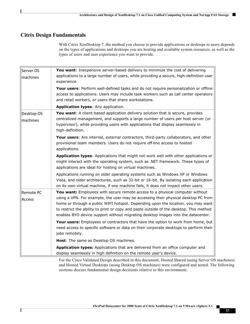
Architecture and Design of XenDesktop 7.1 on Cisco Unified Computing System and NetApp FAS Storage
Citrix Design Fundamentals
With Citrix XenDesktop 7, the method you choose to provide applications or desktops to users depends on the types of applications and desktops you are hosting and available system resources, as well as the types of users and user experience you want to provide.
For the Cisco Validated Design described in this document, Hosted Shared (using Server OS machines) and Hosted Virtual Desktops (using Desktop OS machines) were configured and tested. The following sections discuss fundamental design decisions relative to this environment.
Server OS
machines
You want: Inexpensive server-based delivery to minimize the cost of delivering applications to a large number of users, while providing a secure, high-definition user experience.
Your users: Perform well-defined tasks and do not require personalization or offline access to applications. Users may include task workers such as call center operators and retail workers, or users that share workstations.
Application types: Any application.
Desktop OS
machines
You want: A client-based application delivery solution that is secure, provides centralized management, and supports a large number of users per host server (or hypervisor), while providing users with applications that display seamlessly in high-definition.
Your users: Are internal, external contractors, third-party collaborators, and other provisional team members. Users do not require off‐line access to hosted applications.
Application types: Applications that might not work well with other applications or might interact with the operating system, such as .NET framework. These types of applications are ideal for hosting on virtual machines.
Applications running on older operating systems such as Windows XP or Windows Vista, and older architectures, such as 32-bit or 16-bit. By isolating each application on its own virtual machine, if one machine fails, it does not impact other users.
Remote PC
Access
You want: Employees with secure remote access to a physical computer without using a VPN. For example, the user may be accessing their physical desktop PC from home or through a public WIFI hotspot. Depending upon the location, you may want to restrict the ability to print or copy and paste outside of the desktop. This method enables BYO device support without migrating desktop images into the datacenter.
Your users: Employees or contractors that have the option to work from home, but need access to specific software or data on their corporate desktops to perform their jobs remotely.
Host: The same as Desktop OS machines.
Application types: Applications that are delivered from an office computer and display seamlessly in high definition on the remote user's device.
37FlexPod Datacenter for 2000 Seats of Citrix XenDesktop 7.1 on VMware vSphere 5.1
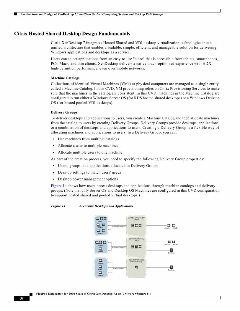
Architecture and Design of XenDesktop 7.1 on Cisco Unified Computing System and NetApp FAS Storage
Citrix Hosted Shared Desktop Design Fundamentals
Citrix XenDesktop 7 integrates Hosted Shared and VDI desktop virtualization technologies into a unified architecture that enables a scalable, simple, efficient, and manageable solution for delivering Windows applications and desktops as a service.
Users can select applications from an easy-to-use "store" that is accessible from tablets, smartphones, PCs, Macs, and thin clients. XenDesktop delivers a native touch-optimized experience with HDX high-definition performance, even over mobile networks.
Machine Catalogs
Collections of identical Virtual Machines (VMs) or physical computers are managed as a single entity called a Machine Catalog. In this CVD, VM provisioning relies on Citrix Provisioning Services to make sure that the machines in the catalog are consistent. In this CVD, machines in the Machine Catalog are configured to run either a Windows Server OS (for RDS hosted shared desktops) or a Windows Desktop OS (for hosted pooled VDI desktops).
Delivery Groups
To deliver desktops and applications to users, you create a Machine Catalog and then allocate machines from the catalog to users by creating Delivery Groups. Delivery Groups provide desktops, applications, or a combination of desktops and applications to users. Creating a Delivery Group is a flexible way of allocating machines and applications to users. In a Delivery Group, you can:
• Use machines from multiple catalogs
• Allocate a user to multiple machines
• Allocate multiple users to one machine
As part of the creation process, you need to specify the following Delivery Group properties:
• Users, groups, and applications allocated to Delivery Groups
• Desktop settings to match users' needs
• Desktop power management options
Figure 14 shows how users access desktops and applications through machine catalogs and delivery groups. (Note that only Server OS and Desktop OS Machines are configured in this CVD configuration to support hosted shared and pooled virtual desktops.)
Figure 14 Accessing Desktops and Applications
38FlexPod Datacenter for 2000 Seats of Citrix XenDesktop 7.1 on VMware vSphere 5.1
Architecture and Design of XenDesktop 7.1 on Cisco Unified Computing System and NetApp FAS Storage
Hypervisor Selection
Citrix XenDesktop is hypervisor-agnostic, so any of the following three hypervisors can be used to host RDS- and VDI-based desktops:
• VMware vSphere: VMware vSphere comprises the management infrastructure or virtual center server software and the hypervisor software that virtualizes the hardware resources on the servers. It offers features like Distributed Resource Scheduler, vMotion, high availability, Storage vMotion, VMFS, and a multipathing storage layer. More information on vSphere can be obtained at the VMware web site: http://www.vmware.com/products/datacenter-virtualization/vsphere/overview.html.
• Hyper-V: Microsoft Windows Server with Hyper-V is available in a Standard, Server Core and free Hyper-V Server versions. More information on Hyper-V can be obtained at the Microsoft web site: http://www.microsoft.com/en-us/server-cloud/windows-server/default.aspx.
• XenServer: Citrix® XenServer® is a complete, managed server virtualization platform built on the powerful Xen® hypervisor. Xen technology is widely acknowledged as the fastest and most secure virtualization software in the industry. XenServer is designed for efficient management of Windows and Linux virtual servers and delivers cost-effective server consolidation and business continuity. More information on XenServer can be obtained at the web site: http://www.citrix.com/products/xenserver/overview.html.
Note For this CVD, the hypervisor used was VMware ESXi 5.1.
Citrix Provisioning Services
Citrix XenDesktop 7.1 can be deployed with or without Citrix Provisioning Services (PVS). The advantage of using Citrix PVS is that it allows computers to be provisioned and re-provisioned in real-time from a single shared-disk image. In this way Citrix PVS greatly reduces the amount of storage required in comparison to other methods of provisioning virtual desktops.
Citrix PVS can create desktops as Pooled or Private:
• Private Desktop: A private desktop is a single desktop assigned to one distinct user.
• Pooled Desktop: A pooled virtual desktop uses Citrix PVS to stream a standard desktop image to multiple desktop instances upon boot.
When considering a PVS deployment, there are some design decisions that need to be made regarding the write cache for the virtual desktop devices that leverage provisioning services. The write cache is a cache of all data that the target device has written. If data is written to the PVS vDisk in a caching mode, the data is not written back to the base vDisk. Instead it is written to a write cache file in one of the following locations:
• Cache on device hard drive. Write cache exists as a file in NTFS format, located on the target-device's hard drive. This write cache option frees up the Provisioning Server since it does not have to process write requests and does not have the finite limitation of RAM.
• Cache on device hard drive persisted. (Experimental Phase) This is the same as "Cache on device hard drive", except that the cache persists. At this time, this method is an experimental feature only, and is only supported for NT6.1 or later (Windows 7 and Windows 2008 R2 and later). This method also requires a different bootstrap.
• Cache in device RAM. Write cache can exist as a temporary file in the target device's RAM. This provides the fastest method of disk access since memory access is always faster than disk access.
39FlexPod Datacenter for 2000 Seats of Citrix XenDesktop 7.1 on VMware vSphere 5.1
Architecture and Design of XenDesktop 7.1 on Cisco Unified Computing System and NetApp FAS Storage
• Cache in device RAM with overflow on hard disk. This method uses VHDX differencing format and is only available for Windows 7 and Server 2008 R2 and later. When RAM is zero, the target device write cache is only written to the local disk. When RAM is not zero, the target device write cache is written to RAM first. When RAM is full, the least recently used block of data is written to the local differencing disk to accommodate newer data on RAM. The amount of RAM specified is the non-paged kernel memory that the target device will consume.
• Cache on a server. Write cache can exist as a temporary file on a Provisioning Server. In this configuration, all writes are handled by the Provisioning Server, which can increase disk I/O and network traffic. For additional security, the Provisioning Server can be configured to encrypt write cache files. Since the write-cache file persists on the hard drive between reboots, encrypted data provides data protection in the event a hard drive is stolen.
• Cache on server persisted. This cache option allows for the saving of changes between reboots. Using this option, after rebooting, a target device is able to retrieve changes made from previous sessions that differ from the read only vDisk image. If a vDisk is set to this method of caching, each target device that accesses the vDisk automatically has a device-specific, writable disk file created. Any changes made to the vDisk image are written to that file, which is not automatically deleted upon shutdown.
The alternative to Citrix Provisioning Services for pooled desktop deployments is Citrix Machine Creation Services (MCS), which is integrated directly with the XenDesktop Studio console.
For this study, we used PVS 7.1 for managing Pooled Desktops with cache on device storage for each virtual machine so that the design would scale to many thousands of desktops. Provisioning Server 7.1 was used for Active Directory machine account creation and management as well as for streaming the shared disk to the hypervisor hosts.
Citrix XenDesktop 7.1 Deployment Examples
You can distribute the components of your deployment among a greater number of servers, or provide greater scalability and failover by increasing the number of controllers in your site. You can install management consoles on separate computers to manage the deployment remotely. A distributed deployment is necessary for an infrastructure based on remote access through NetScaler Gateway (formerly called Access Gateway).
The diagram below shows an example of a distributed components configuration. A simplified version of this configuration is often deployed for an initial proof-of-concept (POC) deployment. The CVD described in this document deploys Citrix XenDesktop in a configuration that resembles this distributed components configuration shown in Figure 15.
40FlexPod Datacenter for 2000 Seats of Citrix XenDesktop 7.1 on VMware vSphere 5.1
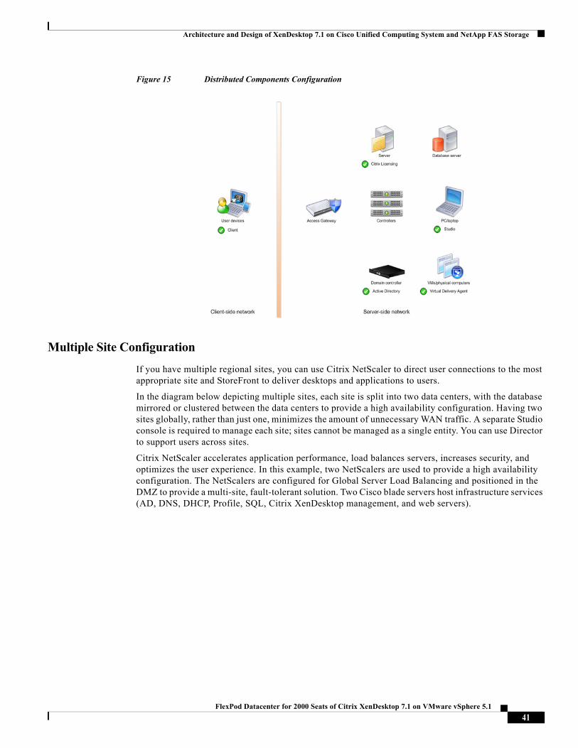
Architecture and Design of XenDesktop 7.1 on Cisco Unified Computing System and NetApp FAS Storage
Figure 15 Distributed Components Configuration
Multiple Site Configuration
If you have multiple regional sites, you can use Citrix NetScaler to direct user connections to the most appropriate site and StoreFront to deliver desktops and applications to users.
In the diagram below depicting multiple sites, each site is split into two data centers, with the database mirrored or clustered between the data centers to provide a high availability configuration. Having two sites globally, rather than just one, minimizes the amount of unnecessary WAN traffic. A separate Studio console is required to manage each site; sites cannot be managed as a single entity. You can use Director to support users across sites.
Citrix NetScaler accelerates application performance, load balances servers, increases security, and optimizes the user experience. In this example, two NetScalers are used to provide a high availability configuration. The NetScalers are configured for Global Server Load Balancing and positioned in the DMZ to provide a multi-site, fault-tolerant solution. Two Cisco blade servers host infrastructure services (AD, DNS, DHCP, Profile, SQL, Citrix XenDesktop management, and web servers).
41FlexPod Datacenter for 2000 Seats of Citrix XenDesktop 7.1 on VMware vSphere 5.1
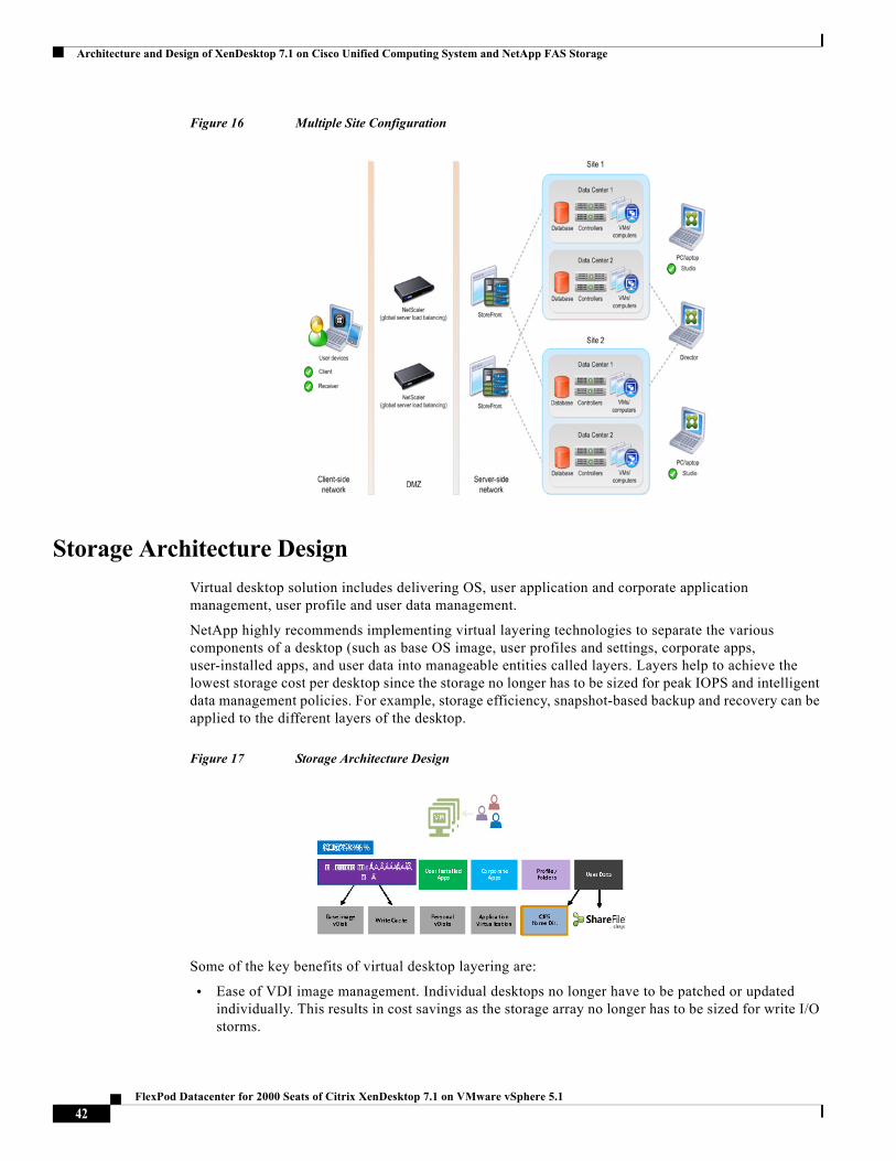
Architecture and Design of XenDesktop 7.1 on Cisco Unified Computing System and NetApp FAS Storage
Figure 16 Multiple Site Configuration
Storage Architecture Design
Virtual desktop solution includes delivering OS, user application and corporate application management, user profile and user data management.
NetApp highly recommends implementing virtual layering technologies to separate the various components of a desktop (such as base OS image, user profiles and settings, corporate apps, user-installed apps, and user data into manageable entities called layers. Layers help to achieve the lowest storage cost per desktop since the storage no longer has to be sized for peak IOPS and intelligent data management policies. For example, storage efficiency, snapshot-based backup and recovery can be applied to the different layers of the desktop.
Figure 17 Storage Architecture Design
Some of the key benefits of virtual desktop layering are:
• Ease of VDI image management. Individual desktops no longer have to be patched or updated individually. This results in cost savings as the storage array no longer has to be sized for write I/O storms.
42FlexPod Datacenter for 2000 Seats of Citrix XenDesktop 7.1 on VMware vSphere 5.1
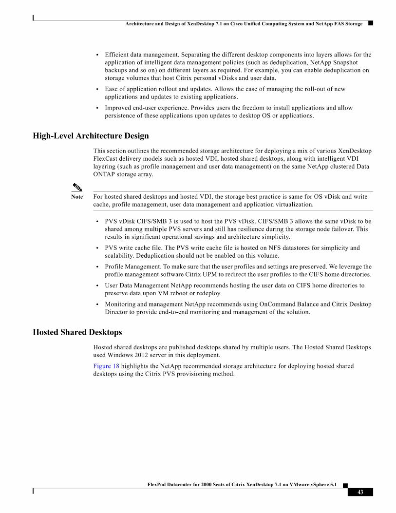
Architecture and Design of XenDesktop 7.1 on Cisco Unified Computing System and NetApp FAS Storage
• Efficient data management. Separating the different desktop components into layers allows for the application of intelligent data management policies (such as deduplication, NetApp Snapshot backups and so on) on different layers as required. For example, you can enable deduplication on storage volumes that host Citrix personal vDisks and user data.
• Ease of application rollout and updates. Allows the ease of managing the roll-out of new applications and updates to existing applications.
• Improved end-user experience. Provides users the freedom to install applications and allow persistence of these applications upon updates to desktop OS or applications.
High-Level Architecture Design
This section outlines the recommended storage architecture for deploying a mix of various XenDesktop FlexCast delivery models such as hosted VDI, hosted shared desktops, along with intelligent VDI layering (such as profile management and user data management) on the same NetApp clustered Data ONTAP storage array.
Note For hosted shared desktops and hosted VDI, the storage best practice is same for OS vDisk and write cache, profile management, user data management and application virtualization.
• PVS vDisk CIFS/SMB 3 is used to host the PVS vDisk. CIFS/SMB 3 allows the same vDisk to be shared among multiple PVS servers and still has resilience during the storage node failover. This results in significant operational savings and architecture simplicity.
• PVS write cache file. The PVS write cache file is hosted on NFS datastores for simplicity and scalability. Deduplication should not be enabled on this volume.
• Profile Management. To make sure that the user profiles and settings are preserved. We leverage the profile management software Citrix UPM to redirect the user profiles to the CIFS home directories.
• User Data Management NetApp recommends hosting the user data on CIFS home directories to preserve data upon VM reboot or redeploy.
• Monitoring and management NetApp recommends using OnCommand Balance and Citrix Desktop Director to provide end-to-end monitoring and management of the solution.
Hosted Shared Desktops
Hosted shared desktops are published desktops shared by multiple users. The Hosted Shared Desktops used Windows 2012 server in this deployment.
Figure 18 highlights the NetApp recommended storage architecture for deploying hosted shared desktops using the Citrix PVS provisioning method.
43FlexPod Datacenter for 2000 Seats of Citrix XenDesktop 7.1 on VMware vSphere 5.1
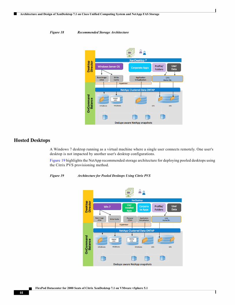
Architecture and Design of XenDesktop 7.1 on Cisco Unified Computing System and NetApp FAS Storage
Figure 18 Recommended Storage Architecture
Hosted Desktops
A Windows 7 desktop running as a virtual machine where a single user connects remotely. One user's desktop is not impacted by another user's desktop configurations.
Figure 19 highlights the NetApp recommended storage architecture for deploying pooled desktops using the Citrix PVS provisioning method.
Figure 19 Architecture for Pooled Desktops Using Citrix PVS
44FlexPod Datacenter for 2000 Seats of Citrix XenDesktop 7.1 on VMware vSphere 5.1
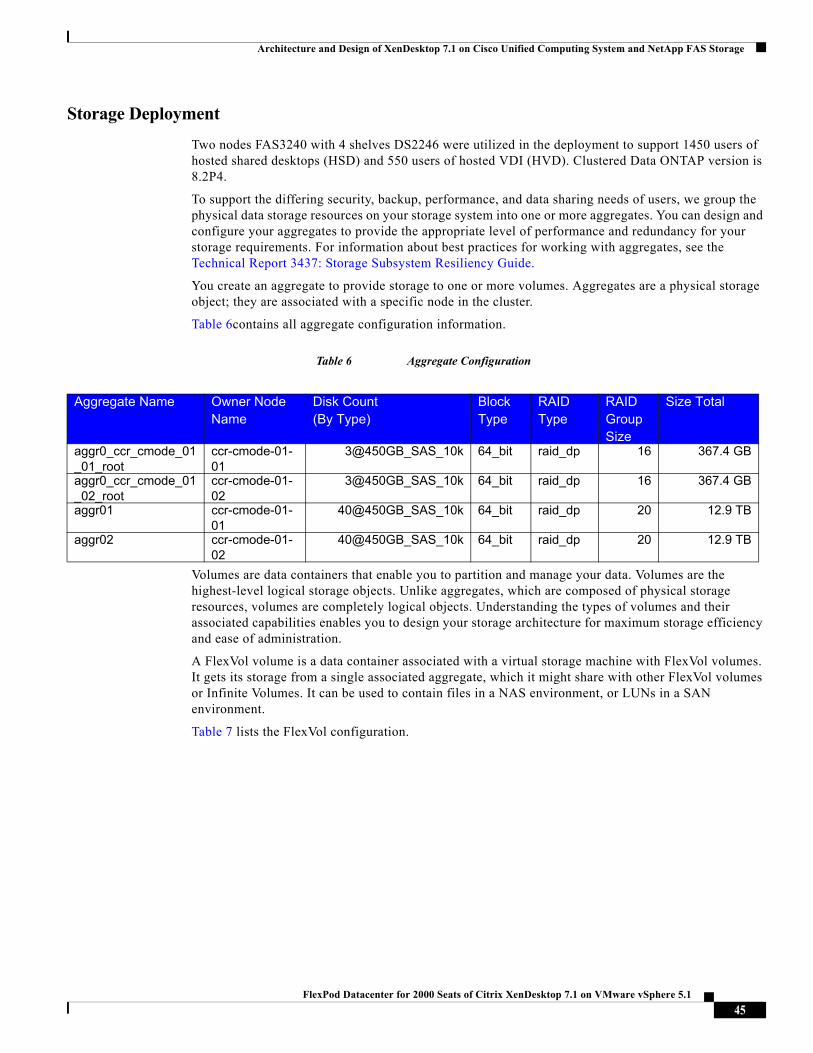
Architecture and Design of XenDesktop 7.1 on Cisco Unified Computing System and NetApp FAS Storage
Storage Deployment
Two nodes FAS3240 with 4 shelves DS2246 were utilized in the deployment to support 1450 users of hosted shared desktops (HSD) and 550 users of hosted VDI (HVD). Clustered Data ONTAP version is 8.2P4.
To support the differing security, backup, performance, and data sharing needs of users, we group the physical data storage resources on your storage system into one or more aggregates. You can design and configure your aggregates to provide the appropriate level of performance and redundancy for your storage requirements. For information about best practices for working with aggregates, see the Technical Report 3437: Storage Subsystem Resiliency Guide.
You create an aggregate to provide storage to one or more volumes. Aggregates are a physical storage object; they are associated with a specific node in the cluster.
Table 6contains all aggregate configuration information.
Table 6 Aggregate Configuration
Volumes are data containers that enable you to partition and manage your data. Volumes are the highest-level logical storage objects. Unlike aggregates, which are composed of physical storage resources, volumes are completely logical objects. Understanding the types of volumes and their associated capabilities enables you to design your storage architecture for maximum storage efficiency and ease of administration.
A FlexVol volume is a data container associated with a virtual storage machine with FlexVol volumes. It gets its storage from a single associated aggregate, which it might share with other FlexVol volumes or Infinite Volumes. It can be used to contain files in a NAS environment, or LUNs in a SAN environment.
Table 7 lists the FlexVol configuration.
Aggregate Name Owner Node Name
Disk Count(By Type)
Block Type
RAID Type
RAID Group Size
Size Total
aggr0_ccr_cmode_01_01_root
ccr-cmode-01-01
3@450GB_SAS_10k 64_bit raid_dp 16 367.4 GB
aggr0_ccr_cmode_01_02_root
ccr-cmode-01-02
3@450GB_SAS_10k 64_bit raid_dp 16 367.4 GB
aggr01 ccr-cmode-01-01
40@450GB_SAS_10k 64_bit raid_dp 20 12.9 TB
aggr02 ccr-cmode-01-02
40@450GB_SAS_10k 64_bit raid_dp 20 12.9 TB
45FlexPod Datacenter for 2000 Seats of Citrix XenDesktop 7.1 on VMware vSphere 5.1
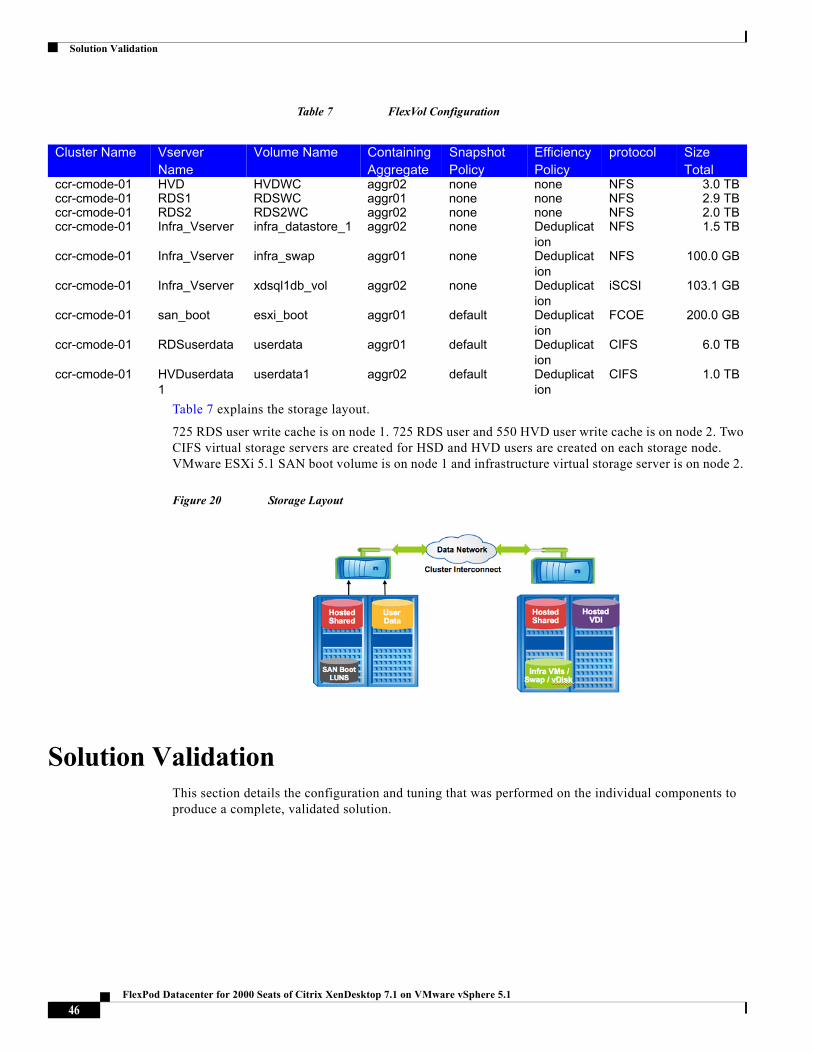
Solution Validation
Table 7 FlexVol Configuration
Table 7 explains the storage layout.
725 RDS user write cache is on node 1. 725 RDS user and 550 HVD user write cache is on node 2. Two CIFS virtual storage servers are created for HSD and HVD users are created on each storage node. VMware ESXi 5.1 SAN boot volume is on node 1 and infrastructure virtual storage server is on node 2.
Figure 20 Storage Layout
Solution ValidationThis section details the configuration and tuning that was performed on the individual components to produce a complete, validated solution.
Cluster Name Vserver Name
Volume Name Containing Aggregate
Snapshot Policy
Efficiency Policy
protocol Size Total
ccr-cmode-01 HVD HVDWC aggr02 none none NFS 3.0 TBccr-cmode-01 RDS1 RDSWC aggr01 none none NFS 2.9 TBccr-cmode-01 RDS2 RDS2WC aggr02 none none NFS 2.0 TBccr-cmode-01 Infra_Vserver infra_datastore_1 aggr02 none Deduplicat
ionNFS 1.5 TB
ccr-cmode-01 Infra_Vserver infra_swap aggr01 none Deduplication
NFS 100.0 GB
ccr-cmode-01 Infra_Vserver xdsql1db_vol aggr02 none Deduplication
iSCSI 103.1 GB
ccr-cmode-01 san_boot esxi_boot aggr01 default Deduplication
FCOE 200.0 GB
ccr-cmode-01 RDSuserdata userdata aggr01 default Deduplication
CIFS 6.0 TB
ccr-cmode-01 HVDuserdata1
userdata1 aggr02 default Deduplication
CIFS 1.0 TB
46FlexPod Datacenter for 2000 Seats of Citrix XenDesktop 7.1 on VMware vSphere 5.1
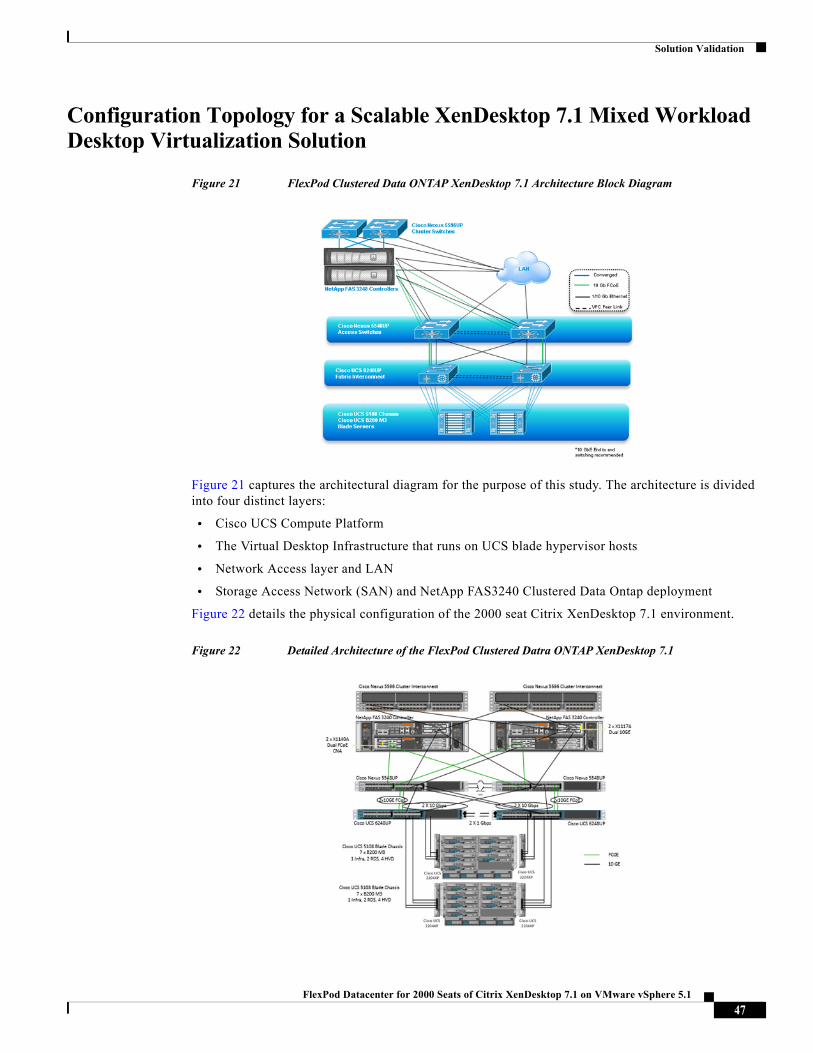
Solution Validation
Configuration Topology for a Scalable XenDesktop 7.1 Mixed Workload Desktop Virtualization Solution
Figure 21 FlexPod Clustered Data ONTAP XenDesktop 7.1 Architecture Block Diagram
Figure 21 captures the architectural diagram for the purpose of this study. The architecture is divided into four distinct layers:
• Cisco UCS Compute Platform
• The Virtual Desktop Infrastructure that runs on UCS blade hypervisor hosts
• Network Access layer and LAN
• Storage Access Network (SAN) and NetApp FAS3240 Clustered Data Ontap deployment
Figure 22 details the physical configuration of the 2000 seat Citrix XenDesktop 7.1 environment.
Figure 22 Detailed Architecture of the FlexPod Clustered Datra ONTAP XenDesktop 7.1
47FlexPod Datacenter for 2000 Seats of Citrix XenDesktop 7.1 on VMware vSphere 5.1
Solution Validation
Cisco Unified Computing System Configuration
This section talks about the Cisco UCS configuration that was done as part of the infrastructure build out. The racking, power and installation of the chassis are described in the install guide (see http://www.cisco.com/en/US/docs/unified_computing/ucs/hw/chassis/install/ucs5108_install.html) and it is beyond the scope of this document. More details about each step can be found in the following documents:
• Cisco UCS Manager Configuration Guides
http://www.cisco.com/en/US/partner/products/ps10281/products_installation_and_configuration_guides_list.html
• Cisco UCS CLI Configuration Guide http://www.cisco.com/en/US/docs/unified_computing/ucs/sw/cli/config/guide/2.1/b_UCSM_CLI_Configuration_Guide_2_1.pdf
• Cisco UCS-M GUI Configuration Guide http://www.cisco.com/en/US/partner/docs/unified_computing/ucs/sw/gui/config/guide/2.1/b_UCSM_GUI_Configuration_Guide_2_1.html
Base Cisco UCS System Configuration
To configure the Cisco Unified Computing System, perform the following steps:
1 Bring up the Fabric Interconnect (FI) and from a serial console connection set the IP address, gateway,
and the hostname of the primary fabric interconnect. Now bring up the second fabric interconnect after
connecting the dual cables between them. The second fabric interconnect automatically recognizes the
primary and ask if you want to be part of the cluster, answer yes and set the IP address, gateway and the
hostname. When this is done all access to the FI can be done remotely. You will also configure the virtual
IP address to connect to the FI, you need a total of three IP address to bring it online. You can also wire up
the chassis to the FI, using either 1, 2, 4 or 8 links per IO Module, depending on your application
bandwidth requirement. We connected four links to each module.
2 Now connect using your favorite browser to the Virtual IP and launch the UCS-Manager. The Java based
UCSM will let you do everything that you could do from the CLI. We will highlight the GUI methodology
here.
48FlexPod Datacenter for 2000 Seats of Citrix XenDesktop 7.1 on VMware vSphere 5.1
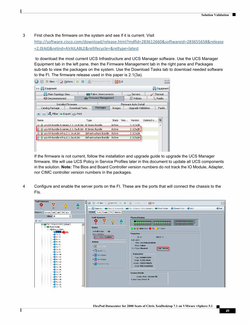
Solution Validation
3 First check the firmware on the system and see if it is current. Visit
http://software.cisco.com/download/release.html?mdfid=283612660&softwareid=283655658&release
=2.0(4d)&relind=AVAILABLE&rellifecycle=&reltype=latest
to download the most current UCS Infrastructure and UCS Manager software. Use the UCS Manager Equipment tab in the left pane, then the Firmware Management tab in the right pane and Packages sub-tab to view the packages on the system. Use the Download Tasks tab to download needed software to the FI. The firmware release used in this paper is 2.1(3a).
If the firmware is not current, follow the installation and upgrade guide to upgrade the UCS Manager firmware. We will use UCS Policy in Service Profiles later in this document to update all UCS components in the solution. Note: The Bios and Board Controller version numbers do not track the IO Module, Adapter, nor CIMC controller version numbers in the packages.
4 Configure and enable the server ports on the FI. These are the ports that will connect the chassis to the
FIs.
49FlexPod Datacenter for 2000 Seats of Citrix XenDesktop 7.1 on VMware vSphere 5.1
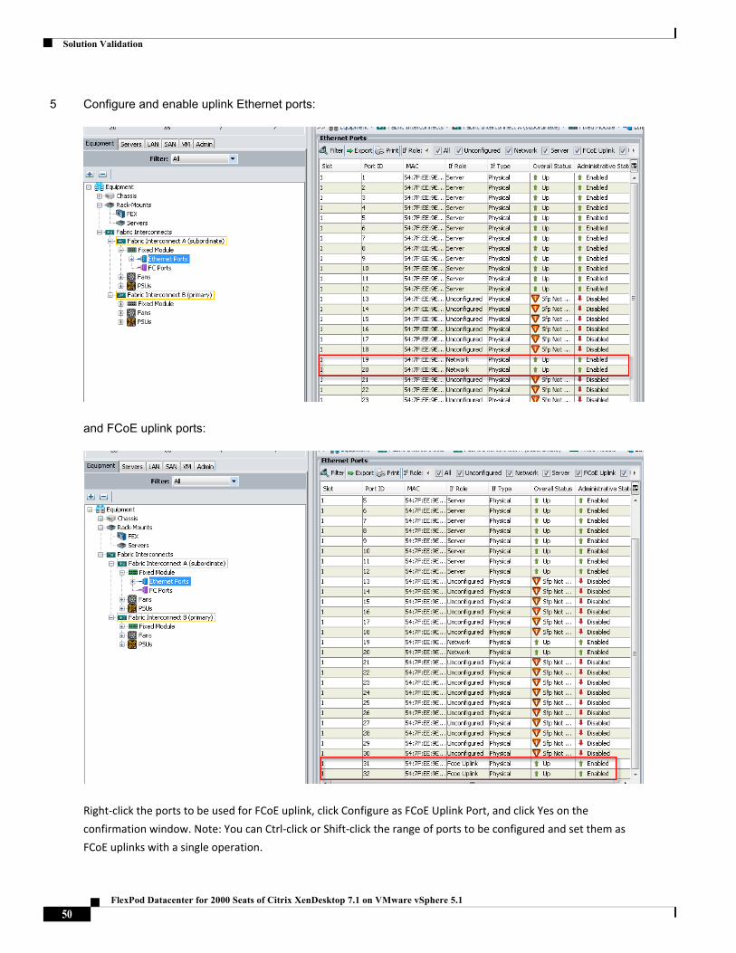
Solution Validation
5 Configure and enable uplink Ethernet ports:
and FCoE uplink ports:
Right‐click the ports to be used for FCoE uplink, click Configure as FCoE Uplink Port, and click Yes on the
confirmation window. Note: You can Ctrl‐click or Shift‐click the range of ports to be configured and set them as
FCoE uplinks with a single operation.
50FlexPod Datacenter for 2000 Seats of Citrix XenDesktop 7.1 on VMware vSphere 5.1
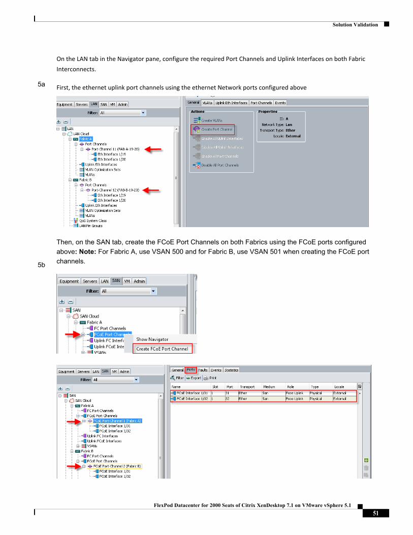
Solution Validation
5a
5b
On the LAN tab in the Navigator pane, configure the required Port Channels and Uplink Interfaces on both Fabric
Interconnects.
First, the ethernet uplink port channels using the ethernet Network ports configured above
Then, on the SAN tab, create the FCoE Port Channels on both Fabrics using the FCoE ports configured
above: Note: For Fabric A, use VSAN 500 and for Fabric B, use VSAN 501 when creating the FCoE port
channels.
51FlexPod Datacenter for 2000 Seats of Citrix XenDesktop 7.1 on VMware vSphere 5.1
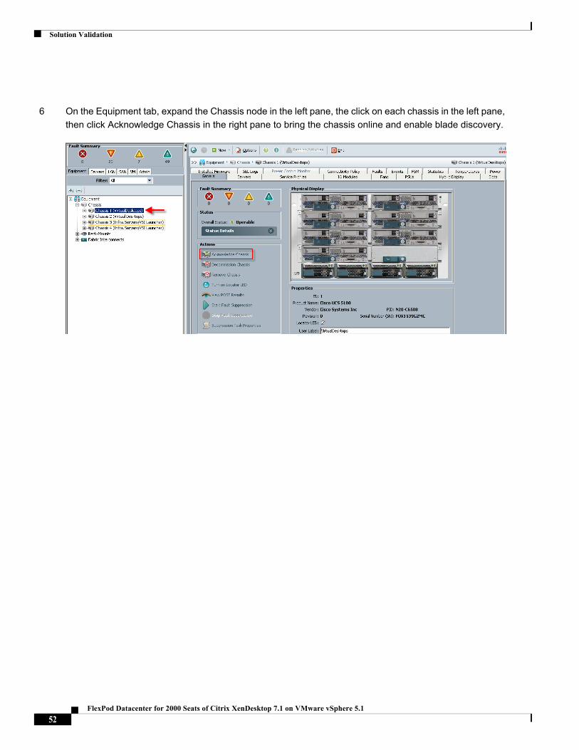
Solution Validation
6 On the Equipment tab, expand the Chassis node in the left pane, the click on each chassis in the left pane,
then click Acknowledge Chassis in the right pane to bring the chassis online and enable blade discovery.
52FlexPod Datacenter for 2000 Seats of Citrix XenDesktop 7.1 on VMware vSphere 5.1
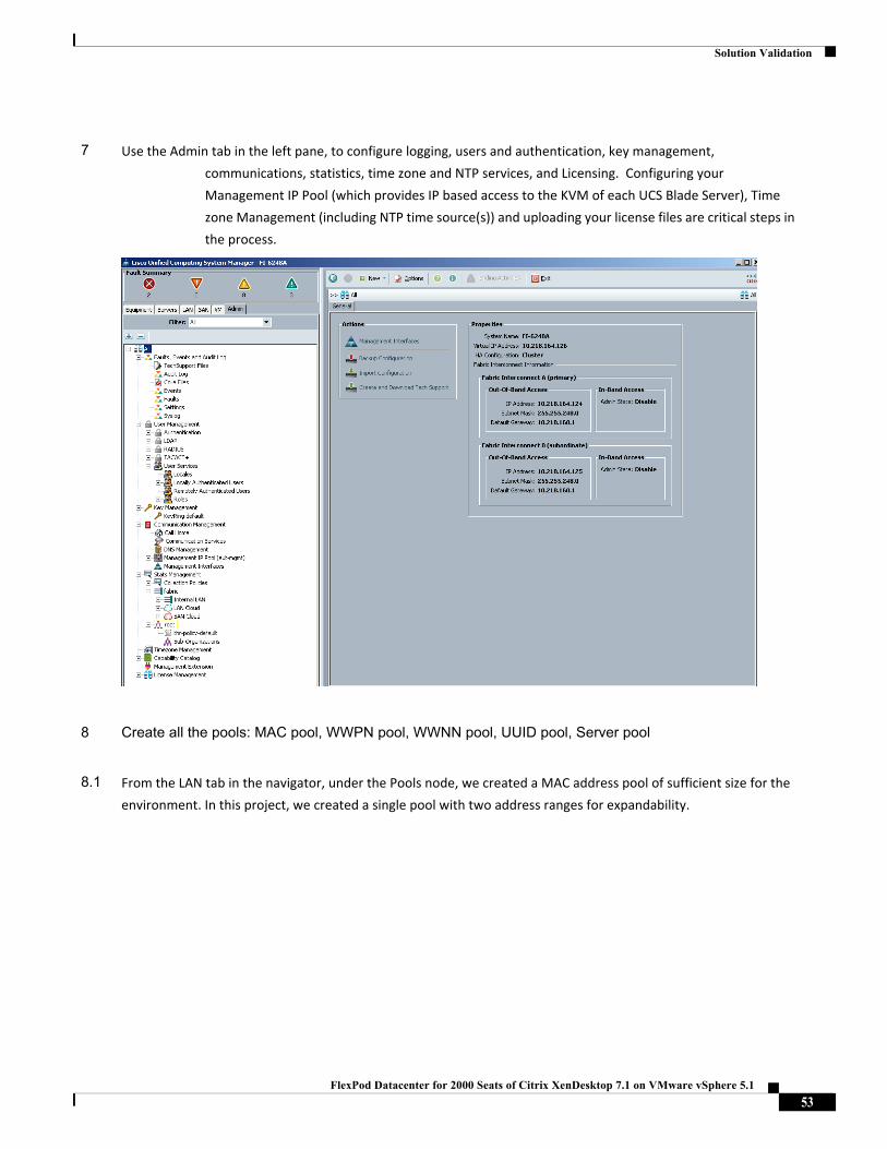
Solution Validation
7 Use the Admin tab in the left pane, to configure logging, users and authentication, key management,
communications, statistics, time zone and NTP services, and Licensing. Configuring your
Management IP Pool (which provides IP based access to the KVM of each UCS Blade Server), Time
zone Management (including NTP time source(s)) and uploading your license files are critical steps in
the process.
8 Create all the pools: MAC pool, WWPN pool, WWNN pool, UUID pool, Server pool
8.1 From the LAN tab in the navigator, under the Pools node, we created a MAC address pool of sufficient size for the
environment. In this project, we created a single pool with two address ranges for expandability.
53FlexPod Datacenter for 2000 Seats of Citrix XenDesktop 7.1 on VMware vSphere 5.1
Solution Validation
8.2 For FCoE and FC connectivity , WWNN and WWPN pools must be created from the SAN tab in the navigator pane, in
the Pools node:
54FlexPod Datacenter for 2000 Seats of Citrix XenDesktop 7.1 on VMware vSphere 5.1
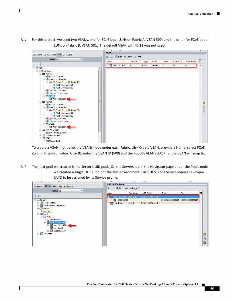
Solution Validation
8.3 For this project, we used two VSANs, one for FCoE boot LUNs on Fabric A, VSAN 500, and the other for FCoE boot
LUNs on Fabric B, VSAN 501. The default VSAN with ID 11 was not used.
To create a VSAN, right‐click the VSANs node under each Fabric, click Create VSAN, provide a Name, select FCoE
Zoning: Disabled, Fabric A (or B), enter the VSAN ID (500) and the FCoE0E VLAN (500) that the VSAN will map to.
8.4 The next pool we created is the Server UUID pool. On the Servers tab in the Navigator page under the Pools node
we created a single UUID Pool for the test environment. Each UCS Blade Server requires a unique
UUID to be assigned by its Service profile.
55FlexPod Datacenter for 2000 Seats of Citrix XenDesktop 7.1 on VMware vSphere 5.1
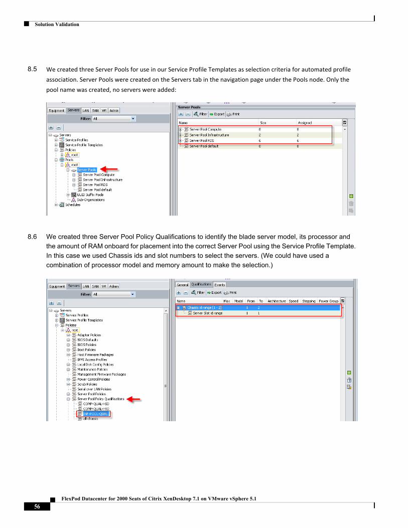
Solution Validation
8.5 We created three Server Pools for use in our Service Profile Templates as selection criteria for automated profile
association. Server Pools were created on the Servers tab in the navigation page under the Pools node. Only the
pool name was created, no servers were added:
8.6 We created three Server Pool Policy Qualifications to identify the blade server model, its processor and
the amount of RAM onboard for placement into the correct Server Pool using the Service Profile Template.
In this case we used Chassis ids and slot numbers to select the servers. (We could have used a
combination of processor model and memory amount to make the selection.)
56FlexPod Datacenter for 2000 Seats of Citrix XenDesktop 7.1 on VMware vSphere 5.1
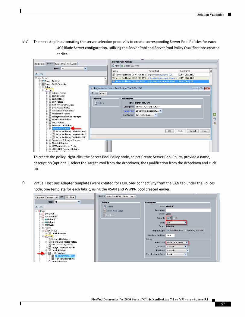
Solution Validation
8.7 The next step in automating the server selection process is to create corresponding Server Pool Policies for each
UCS Blade Server configuration, utilizing the Server Pool and Server Pool Policy Qualifications created
earlier.
To create the policy, right‐click the Server Pool Policy node, select Create Server Pool Policy, provide a name,
description (optional), select the Target Pool from the dropdown, the Qualification from the dropdown and click
OK.
9 Virtual Host Bus Adapter templates were created for FCoE SAN connectivity from the SAN tab under the Polices
node, one template for each fabric, using the VSAN and WWPN pool created earlier:
57FlexPod Datacenter for 2000 Seats of Citrix XenDesktop 7.1 on VMware vSphere 5.1
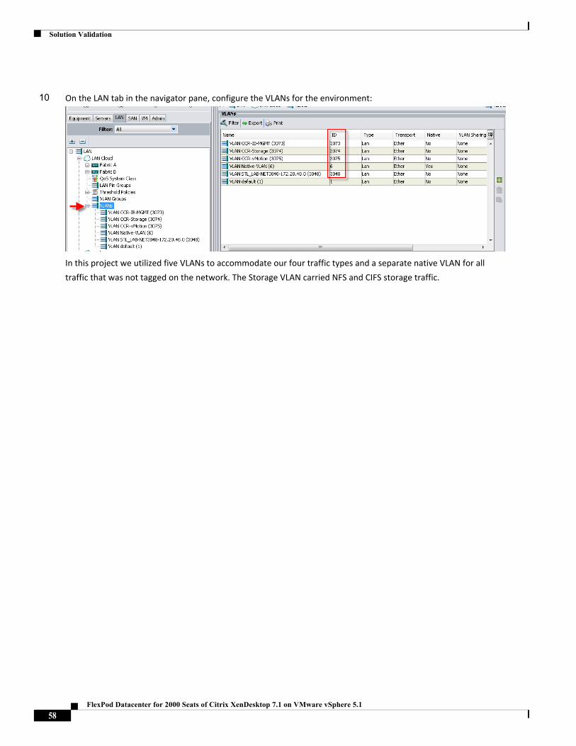
Solution Validation
10 On the LAN tab in the navigator pane, configure the VLANs for the environment:
In this project we utilized five VLANs to accommodate our four traffic types and a separate native VLAN for all
traffic that was not tagged on the network. The Storage VLAN carried NFS and CIFS storage traffic.
58FlexPod Datacenter for 2000 Seats of Citrix XenDesktop 7.1 on VMware vSphere 5.1
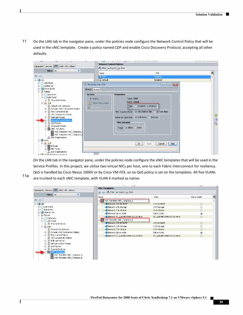
Solution Validation
11
11a
On the LAN tab in the navigator pane, under the policies node configure the Network Control Policy that will be
used in the vNIC template. Create a policy named CDP and enable Cisco Discovery Protocol, accepting all other
defaults.
On the LAN tab in the navigator pane, under the policies node configure the vNIC templates that will be used in the
Service Profiles. In this project, we utilize two virtual NICs per host, one to each Fabric Interconnect for resiliency.
QoS is handled by Cisco Nexus 1000V or by Cisco VM‐FEX, so no QoS policy is set on the templates. All five VLANs
are trunked to each vNIC template, with VLAN 6 marked as native.
59FlexPod Datacenter for 2000 Seats of Citrix XenDesktop 7.1 on VMware vSphere 5.1
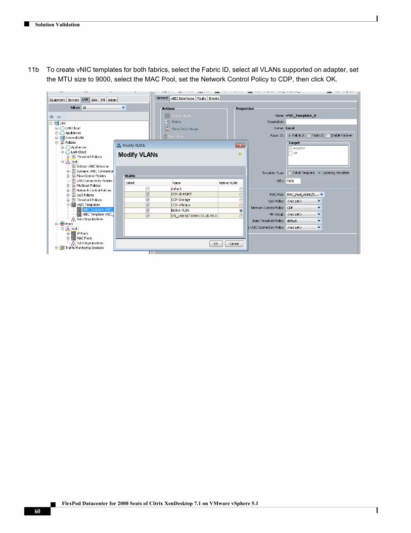
Solution Validation
11b To create vNIC templates for both fabrics, select the Fabric ID, select all VLANs supported on adapter, set
the MTU size to 9000, select the MAC Pool, set the Network Control Policy to CDP, then click OK.
60FlexPod Datacenter for 2000 Seats of Citrix XenDesktop 7.1 on VMware vSphere 5.1
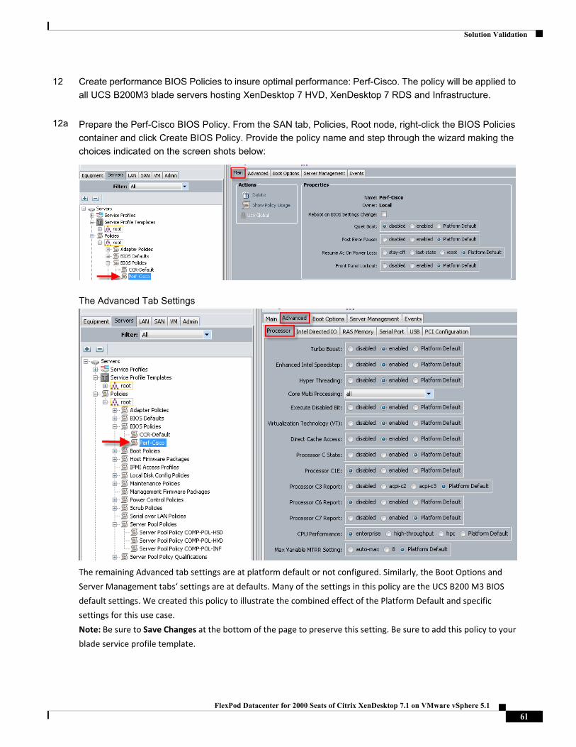
Solution Validation
12
12a
Create performance BIOS Policies to insure optimal performance: Perf-Cisco. The policy will be applied to
all UCS B200M3 blade servers hosting XenDesktop 7 HVD, XenDesktop 7 RDS and Infrastructure.
Prepare the Perf-Cisco BIOS Policy. From the SAN tab, Policies, Root node, right-click the BIOS Policies
container and click Create BIOS Policy. Provide the policy name and step through the wizard making the
choices indicated on the screen shots below:
The Advanced Tab Settings
The remaining Advanced tab settings are at platform default or not configured. Similarly, the Boot Options and
Server Management tabs‘ settings are at defaults. Many of the settings in this policy are the UCS B200 M3 BIOS
default settings. We created this policy to illustrate the combined effect of the Platform Default and specific
settings for this use case.
Note: Be sure to Save Changes at the bottom of the page to preserve this setting. Be sure to add this policy to your
blade service profile template.
61FlexPod Datacenter for 2000 Seats of Citrix XenDesktop 7.1 on VMware vSphere 5.1
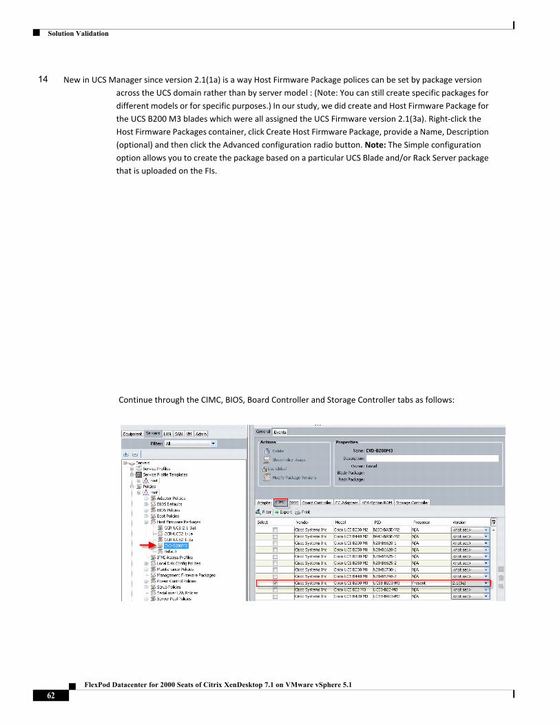
Solution Validation
Continue through the CIMC, BIOS, Board Controller and Storage Controller tabs as follows:
14 New in UCS Manager since version 2.1(1a) is a way Host Firmware Package polices can be set by package version
across the UCS domain rather than by server model : (Note: You can still create specific packages for
different models or for specific purposes.) In our study, we did create and Host Firmware Package for
the UCS B200 M3 blades which were all assigned the UCS Firmware version 2.1(3a). Right‐click the
Host Firmware Packages container, click Create Host Firmware Package, provide a Name, Description
(optional) and then click the Advanced configuration radio button. Note: The Simple configuration
option allows you to create the package based on a particular UCS Blade and/or Rack Server package
that is uploaded on the FIs.
62FlexPod Datacenter for 2000 Seats of Citrix XenDesktop 7.1 on VMware vSphere 5.1
Solution Validation
63FlexPod Datacenter for 2000 Seats of Citrix XenDesktop 7.1 on VMware vSphere 5.1
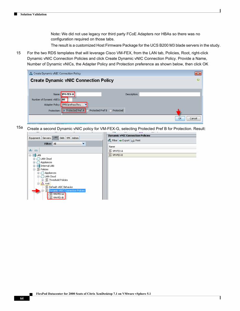
Solution Validation
Note: We did not use legacy nor third party FCoE Adapters nor HBAs so there was no configuration required on those tabs.
The result is a customized Host Firmware Package for the UCS B200 M3 blade servers in the study.
15
15a
For the two RDS templates that will leverage Cisco VM-FEX, from the LAN tab, Policies, Root, right-click
Dynamic vNIC Connection Policies and click Create Dynamic vNIC Connection Policy. Provide a Name,
Number of Dynamic vNICs, the Adapter Policy and Protection preference as shown below, then click OK
Create a second Dynamic vNIC policy for VM-FEX-G, selecting Protected Pref B for Protection. Result:
64FlexPod Datacenter for 2000 Seats of Citrix XenDesktop 7.1 on VMware vSphere 5.1
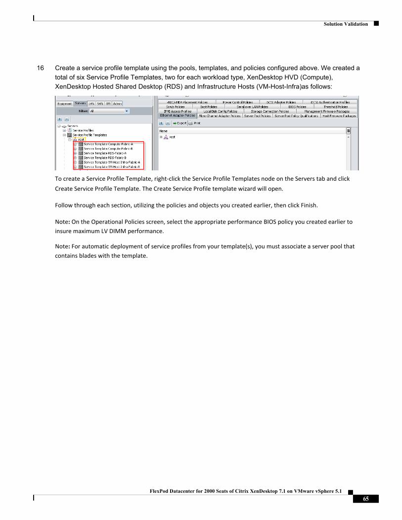
Solution Validation
16 Create a service profile template using the pools, templates, and policies configured above. We created a
total of six Service Profile Templates, two for each workload type, XenDesktop HVD (Compute),
XenDesktop Hosted Shared Desktop (RDS) and Infrastructure Hosts (VM-Host-Infra)as follows:
To create a Service Profile Template, right‐click the Service Profile Templates node on the Servers tab and click
Create Service Profile Template. The Create Service Profile template wizard will open.
Follow through each section, utilizing the policies and objects you created earlier, then click Finish.
Note: On the Operational Policies screen, select the appropriate performance BIOS policy you created earlier to
insure maximum LV DIMM performance.
Note: For automatic deployment of service profiles from your template(s), you must associate a server pool that
contains blades with the template.
65FlexPod Datacenter for 2000 Seats of Citrix XenDesktop 7.1 on VMware vSphere 5.1
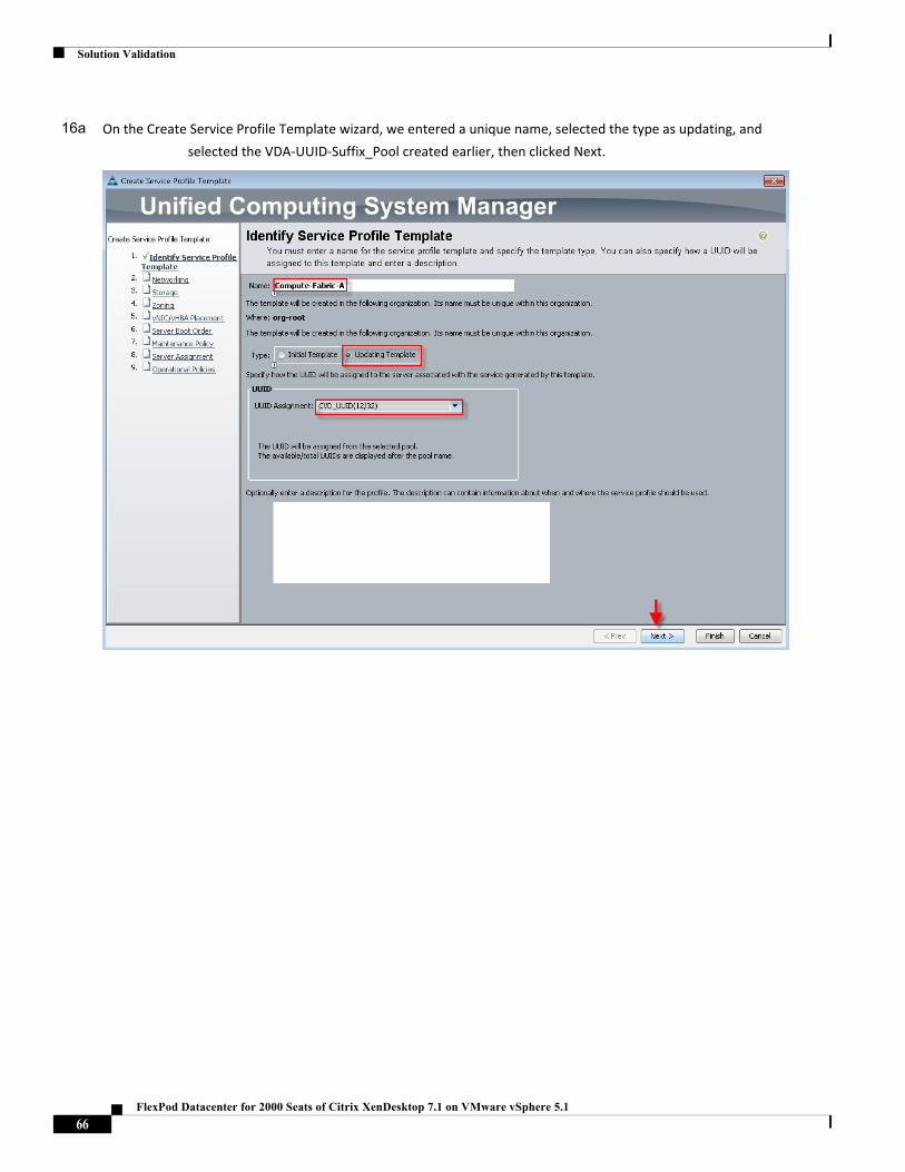
Solution Validation
16a On the Create Service Profile Template wizard, we entered a unique name, selected the type as updating, and
selected the VDA‐UUID‐Suffix_Pool created earlier, then clicked Next.
66FlexPod Datacenter for 2000 Seats of Citrix XenDesktop 7.1 on VMware vSphere 5.1
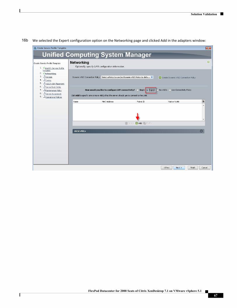
Solution Validation
16b We selected the Expert configuration option on the Networking page and clicked Add in the adapters window:
67FlexPod Datacenter for 2000 Seats of Citrix XenDesktop 7.1 on VMware vSphere 5.1
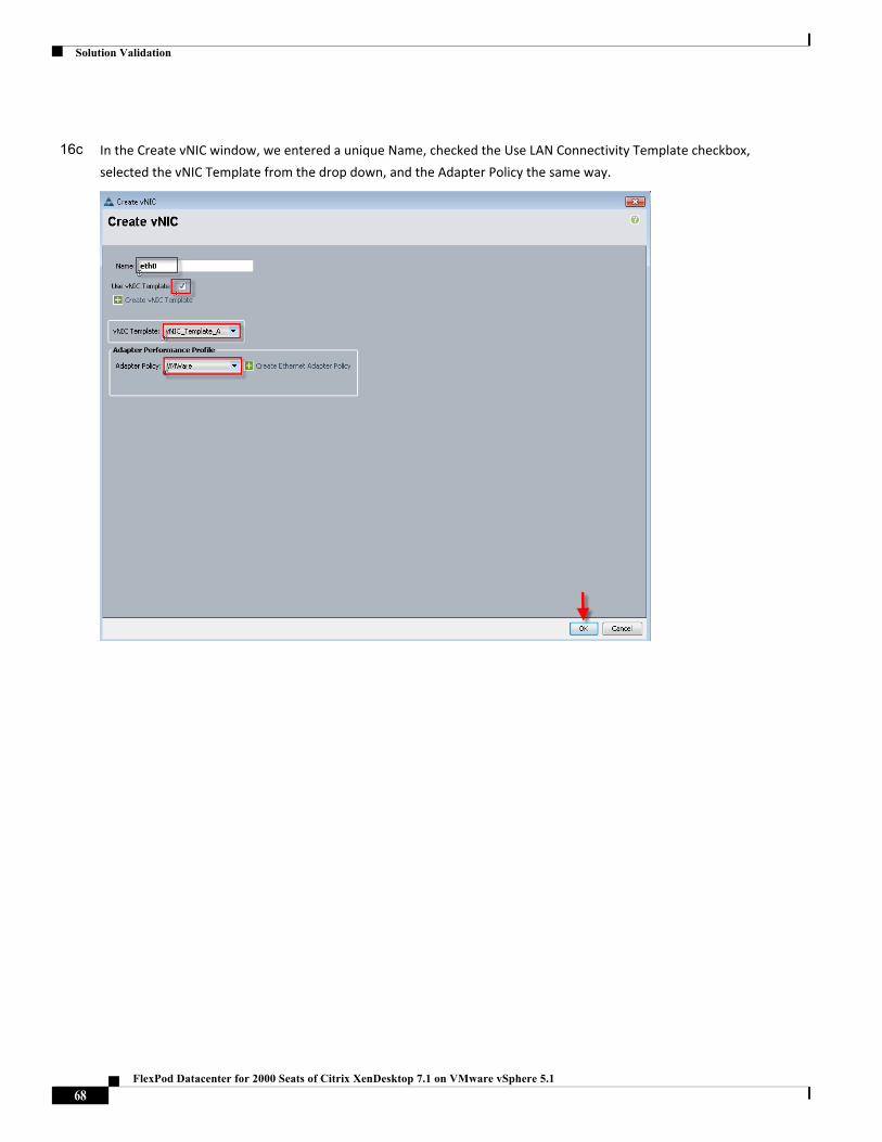
Solution Validation
16c In the Create vNIC window, we entered a unique Name, checked the Use LAN Connectivity Template checkbox,
selected the vNIC Template from the drop down, and the Adapter Policy the same way.
68FlexPod Datacenter for 2000 Seats of Citrix XenDesktop 7.1 on VMware vSphere 5.1
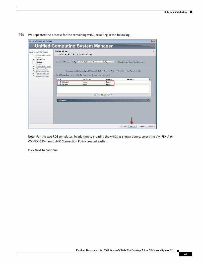
Solution Validation
16d We repeated the process for the remaining vNIC , resulting in the following:
Note: For the two RDS templates, in addition to creating the vNICs as shown above, select the VM‐FEX‐A or
VM‐FEX‐B Dynamic vNIC Connection Policy created earlier.
Click Next to continue.
69FlexPod Datacenter for 2000 Seats of Citrix XenDesktop 7.1 on VMware vSphere 5.1
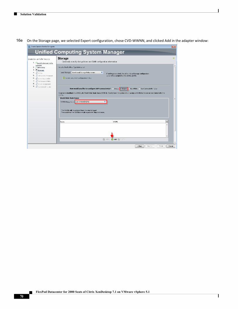
Solution Validation
16e On the Storage page, we selected Expert configuration, chose CVD‐WWNN, and clicked Add in the adapter window:
70FlexPod Datacenter for 2000 Seats of Citrix XenDesktop 7.1 on VMware vSphere 5.1
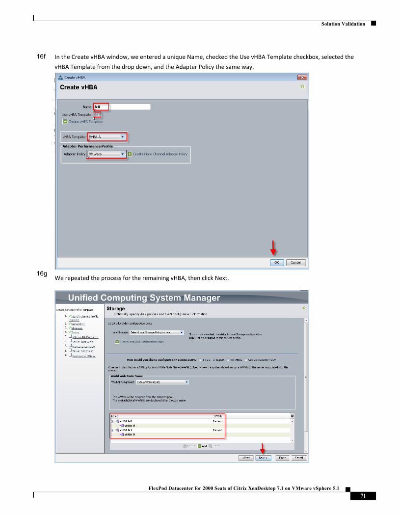
Solution Validation
16f
16g
In the Create vHBA window, we entered a unique Name, checked the Use vHBA Template checkbox, selected the
vHBA Template from the drop down, and the Adapter Policy the same way.
We repeated the process for the remaining vHBA, then click Next.
71FlexPod Datacenter for 2000 Seats of Citrix XenDesktop 7.1 on VMware vSphere 5.1
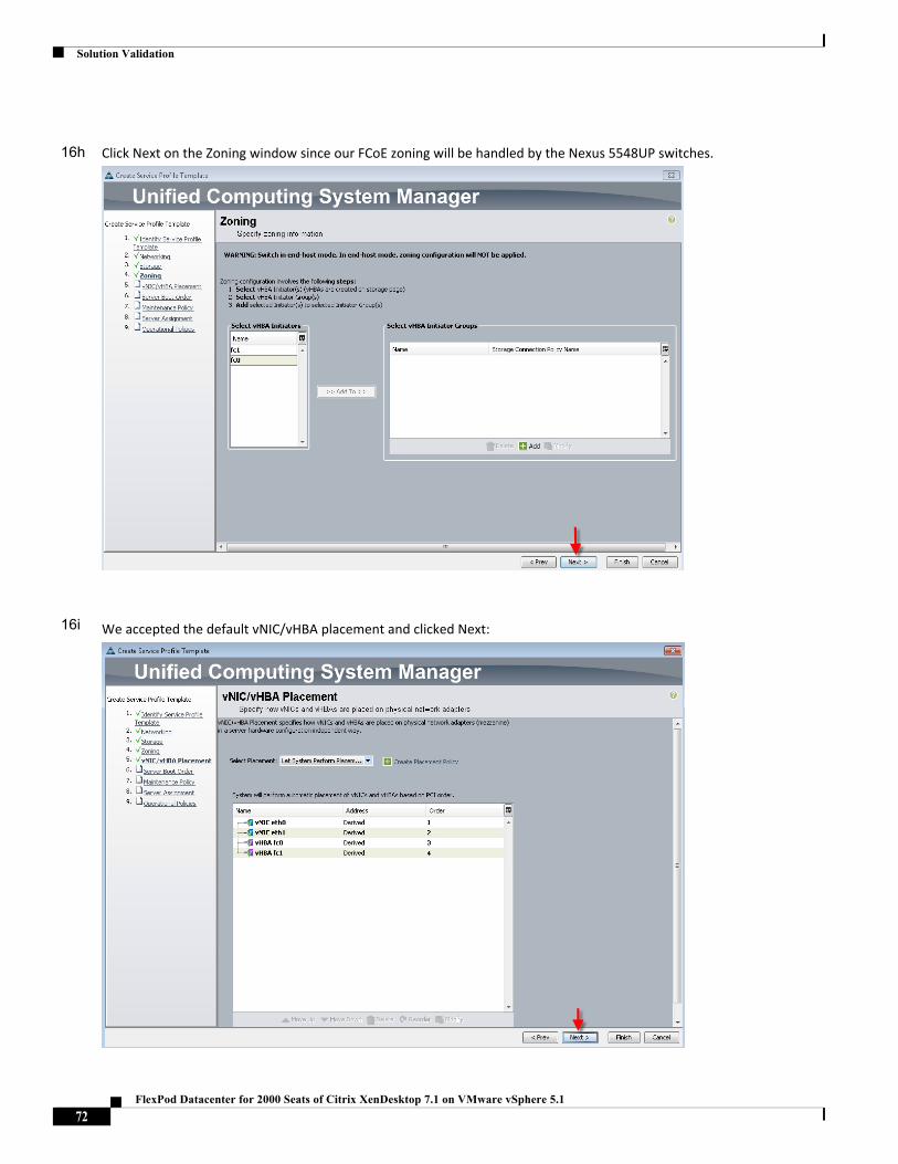
Solution Validation
16h
16i
Click Next on the Zoning window since our FCoE zoning will be handled by the Nexus 5548UP switches.
We accepted the default vNIC/vHBA placement and clicked Next:
72FlexPod Datacenter for 2000 Seats of Citrix XenDesktop 7.1 on VMware vSphere 5.1
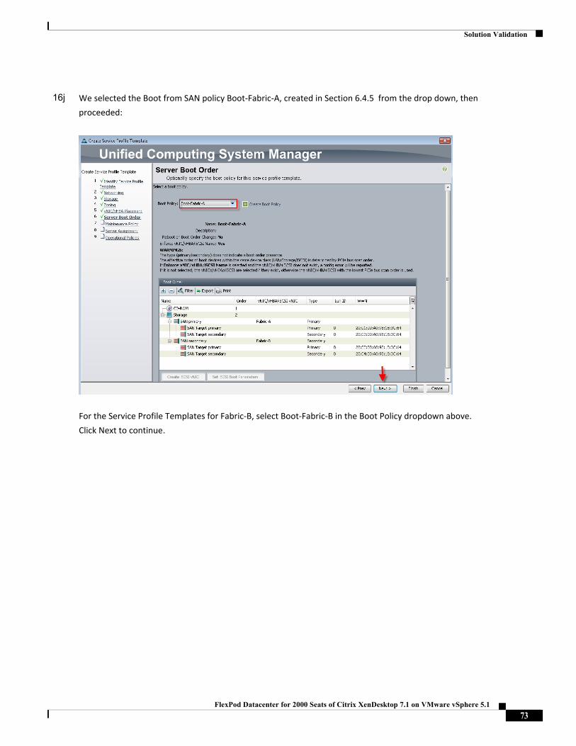
Solution Validation
16j We selected the Boot from SAN policy Boot‐Fabric‐A, created in Section 6.4.5 from the drop down, then
proceeded:
For the Service Profile Templates for Fabric‐B, select Boot‐Fabric‐B in the Boot Policy dropdown above.
Click Next to continue.
73FlexPod Datacenter for 2000 Seats of Citrix XenDesktop 7.1 on VMware vSphere 5.1
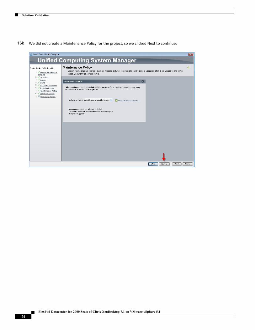
Solution Validation
16k We did not create a Maintenance Policy for the project, so we clicked Next to continue:
74FlexPod Datacenter for 2000 Seats of Citrix XenDesktop 7.1 on VMware vSphere 5.1
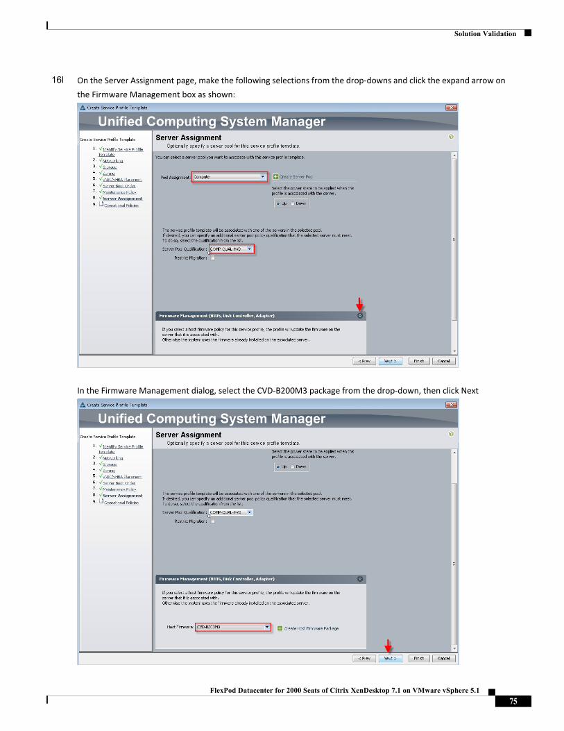
Solution Validation
16l On the Server Assignment page, make the following selections from the drop‐downs and click the expand arrow on
the Firmware Management box as shown:
In the Firmware Management dialog, select the CVD‐B200M3 package from the drop‐down, then click Next
75FlexPod Datacenter for 2000 Seats of Citrix XenDesktop 7.1 on VMware vSphere 5.1
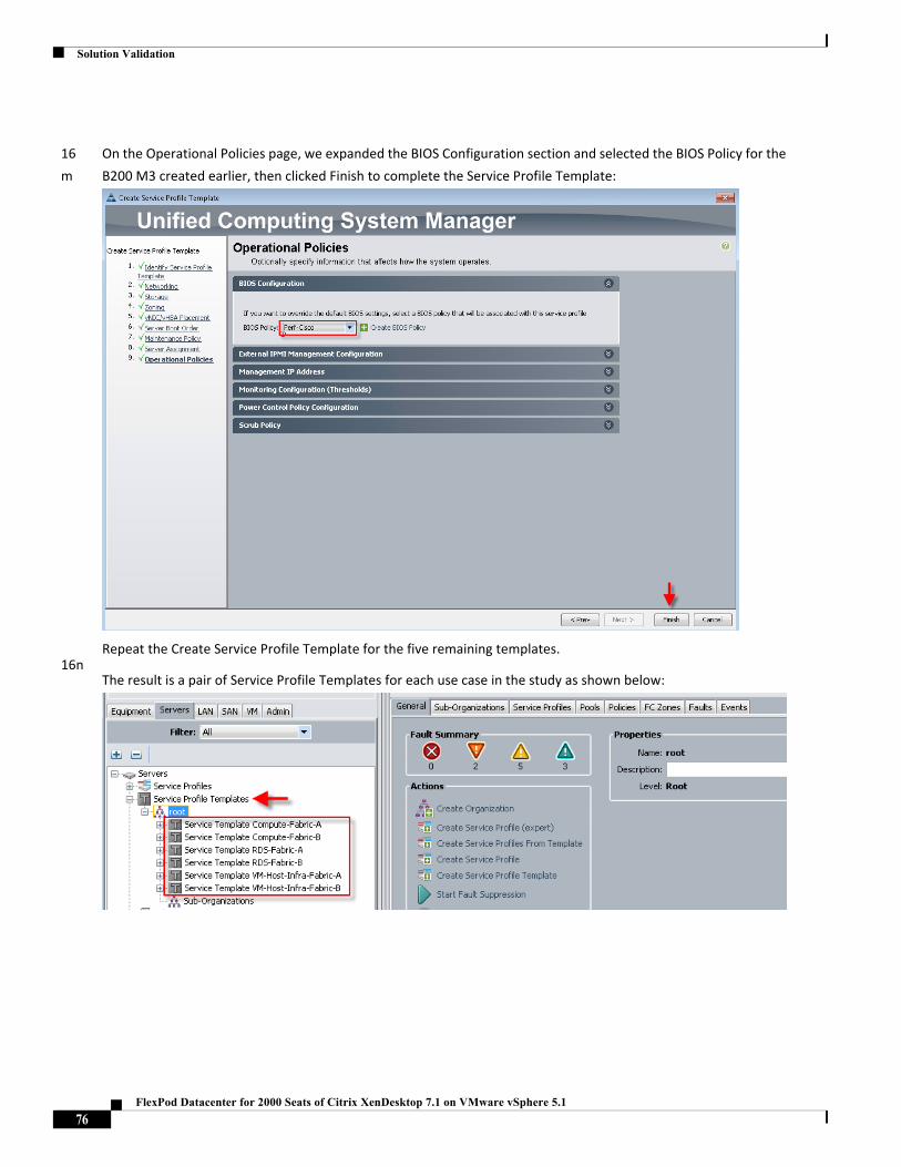
Solution Validation
16
m
16n
On the Operational Policies page, we expanded the BIOS Configuration section and selected the BIOS Policy for the
B200 M3 created earlier, then clicked Finish to complete the Service Profile Template:
Repeat the Create Service Profile Template for the five remaining templates.
The result is a pair of Service Profile Templates for each use case in the study as shown below:
76FlexPod Datacenter for 2000 Seats of Citrix XenDesktop 7.1 on VMware vSphere 5.1
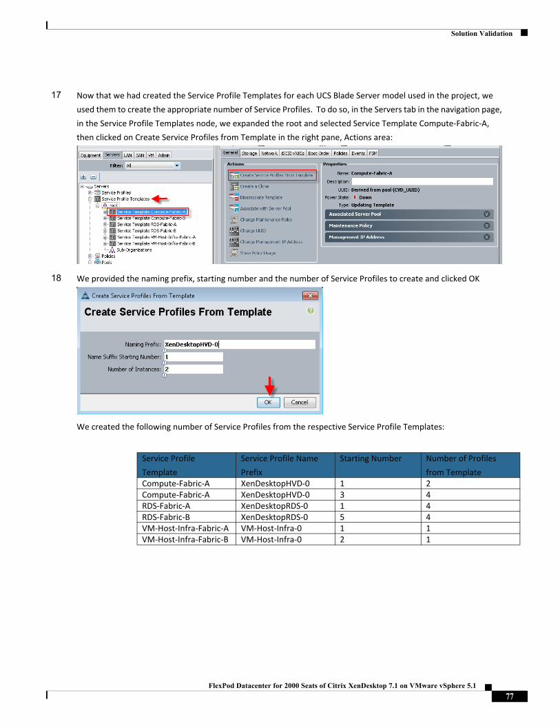
Solution Validation
17 Now that we had created the Service Profile Templates for each UCS Blade Server model used in the project, we
used them to create the appropriate number of Service Profiles. To do so, in the Servers tab in the navigation page,
in the Service Profile Templates node, we expanded the root and selected Service Template Compute‐Fabric‐A,
then clicked on Create Service Profiles from Template in the right pane, Actions area:
18 We provided the naming prefix, starting number and the number of Service Profiles to create and clicked OK
We created the following number of Service Profiles from the respective Service Profile Templates:
Service Profile
Template
Service Profile Name
Prefix
Starting Number Number of Profiles
from TemplateCompute‐Fabric‐A XenDesktopHVD‐0 1 2Compute‐Fabric‐A XenDesktopHVD‐0 3 4RDS‐Fabric‐A XenDesktopRDS‐0 1 4RDS‐Fabric‐B XenDesktopRDS‐0 5 4VM‐Host‐Infra‐Fabric‐A VM‐Host‐Infra‐0 1 1VM‐Host‐Infra‐Fabric‐B VM‐Host‐Infra‐0 2 1
77FlexPod Datacenter for 2000 Seats of Citrix XenDesktop 7.1 on VMware vSphere 5.1
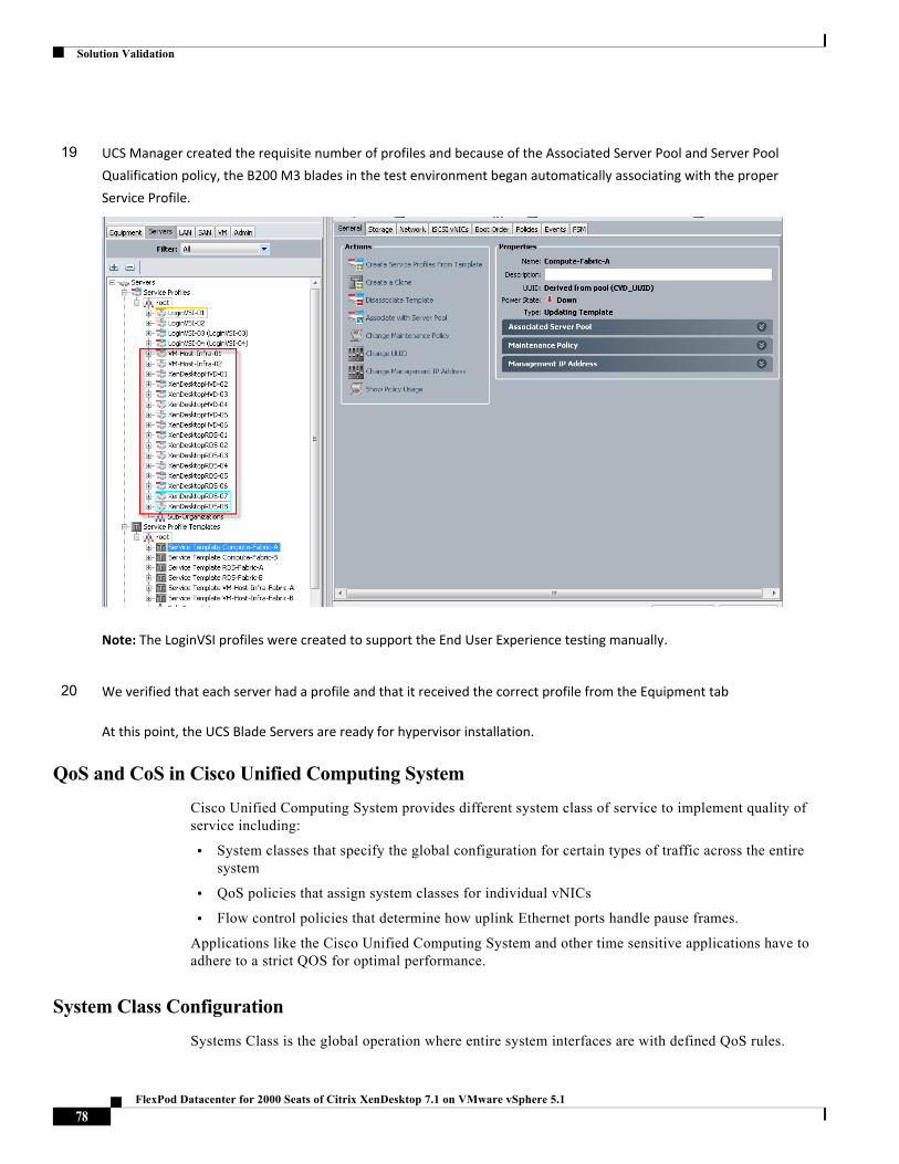
Solution Validation
QoS and CoS in Cisco Unified Computing System
Cisco Unified Computing System provides different system class of service to implement quality of service including:
• System classes that specify the global configuration for certain types of traffic across the entire system
• QoS policies that assign system classes for individual vNICs
• Flow control policies that determine how uplink Ethernet ports handle pause frames.
Applications like the Cisco Unified Computing System and other time sensitive applications have to adhere to a strict QOS for optimal performance.
System Class Configuration
Systems Class is the global operation where entire system interfaces are with defined QoS rules.
19 UCS Manager created the requisite number of profiles and because of the Associated Server Pool and Server Pool
Qualification policy, the B200 M3 blades in the test environment began automatically associating with the proper
Service Profile.
Note: The LoginVSI profiles were created to support the End User Experience testing manually.
20 We verified that each server had a profile and that it received the correct profile from the Equipment tab
At this point, the UCS Blade Servers are ready for hypervisor installation.
78FlexPod Datacenter for 2000 Seats of Citrix XenDesktop 7.1 on VMware vSphere 5.1
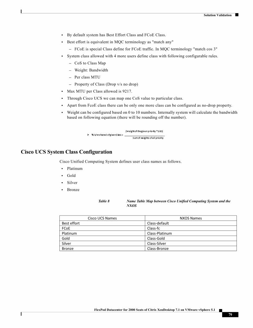
Solution Validation
• By default system has Best Effort Class and FCoE Class.
• Best effort is equivalent in MQC terminology as "match any"
– FCoE is special Class define for FCoE traffic. In MQC terminology "match cos 3"
• System class allowed with 4 more users define class with following configurable rules.
– CoS to Class Map
– Weight: Bandwidth
– Per class MTU
– Property of Class (Drop v/s no drop)
• Max MTU per Class allowed is 9217.
• Through Cisco UCS we can map one CoS value to particular class.
• Apart from FcoE class there can be only one more class can be configured as no-drop property.
• Weight can be configured based on 0 to 10 numbers. Internally system will calculate the bandwidth based on following equation (there will be rounding off the number).
Cisco UCS System Class Configuration
Cisco Unified Computing System defines user class names as follows.
• Platinum
• Gold
• Silver
• Bronze
Table 8 Name Table Map between Cisco Unified Computing System and the NXOS
Cisco UCS Names NXOS NamesBest effort Class‐defaultFCoE Class‐fcPlatinum Class‐PlatinumGold Class‐GoldSilver Class‐SilverBronze Class‐Bronze
79FlexPod Datacenter for 2000 Seats of Citrix XenDesktop 7.1 on VMware vSphere 5.1
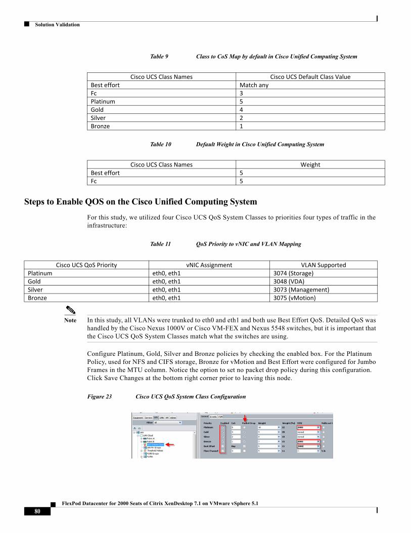
Solution Validation
Table 9 Class to CoS Map by default in Cisco Unified Computing System
Table 10 Default Weight in Cisco Unified Computing System
Steps to Enable QOS on the Cisco Unified Computing System
For this study, we utilized four Cisco UCS QoS System Classes to priorities four types of traffic in the infrastructure:
Table 11 QoS Priority to vNIC and VLAN Mapping
Note In this study, all VLANs were trunked to eth0 and eth1 and both use Best Effort QoS. Detailed QoS was handled by the Cisco Nexus 1000V or Cisco VM-FEX and Nexus 5548 switches, but it is important that the Cisco UCS QoS System Classes match what the switches are using.
Configure Platinum, Gold, Silver and Bronze policies by checking the enabled box. For the Platinum Policy, used for NFS and CIFS storage, Bronze for vMotion and Best Effort were configured for Jumbo Frames in the MTU column. Notice the option to set no packet drop policy during this configuration. Click Save Changes at the bottom right corner prior to leaving this node.
Figure 23 Cisco UCS QoS System Class Configuration
Cisco UCS Class Names Cisco UCS Default Class ValueBest effort Match anyFc 3Platinum 5Gold 4Silver 2Bronze 1
Cisco UCS Class Names WeightBest effort 5Fc 5
Cisco UCS QoS Priority vNIC Assignment VLAN SupportedPlatinum eth0, eth1 3074 (Storage)Gold eth0, eth1 3048 (VDA)Silver eth0, eth1 3073 (Management)Bronze eth0, eth1 3075 (vMotion)
80FlexPod Datacenter for 2000 Seats of Citrix XenDesktop 7.1 on VMware vSphere 5.1
Solution Validation
This is a unique value proposition for Cisco UCS with respect to end-to-end QOS. For example, we have a VLAN for the NetApp storage, configured Platinum policy with Jumbo frames and get an end-to-end QOS and performance guarantees from the blade servers running the Cisco Nexus 1000V virtual distributed switches or Cisco VM-FEX through the Nexus 5548UP access layer switches.
LAN Configuration
The access layer LAN configuration consists of a pair of Cisco Nexus 5548s (N5Ks), a family member of our low-latency, line-rate, 10 Gigabit Ethernet and FCoE switches for our VDI deployment.
Cisco UCS and NetApp Ethernet Connectivity
Two 10 Gigabit Ethernet uplink ports are configured on each of the Cisco UCS 6248 fabric interconnects, and they are connected to the Cisco Nexus 5548 pair in a bow tie manner as shown below in a port channel.
The 6248 Fabric Interconnect is in End host mode, as we are doing both FCoE Over Ethernet (FCoE) as well as Ethernet (NAS) data access as per the recommended best practice of the Cisco Unified Computing System. We built this out for scale and have provisioned 20 GB per Fabric Interconnect for ethernet (Figure 32) and 20 GB per Fabric Interconnect for FCoE (Figure 33).
The FAS3240s are also equipped with two dual-port 10G X1117A adapters which are connected to the pair of N5Ks downstream. Both paths are active providing failover capability. This allows end-to-end 10G access for file-based storage traffic. We have implemented jumbo frames on the ports and have priority flow control on, with Platinum CoS and QoS assigned to the vNICs carrying the storage data access on the Fabric Interconnects.
Note The upstream configuration is beyond the scope of this document; there are some good reference document [4] that talks about best practices of using the Cisco Nexus 5000 and 7000 Series Switches. New with the Cisco Nexus 5500 series is an available Layer 3 module that was not used in these tests and that will not be covered in this document.
81FlexPod Datacenter for 2000 Seats of Citrix XenDesktop 7.1 on VMware vSphere 5.1
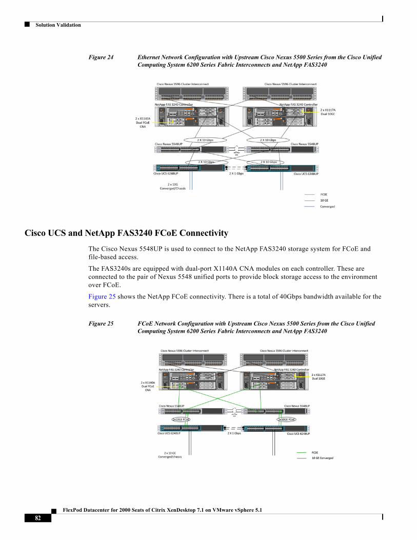
Solution Validation
Figure 24 Ethernet Network Configuration with Upstream Cisco Nexus 5500 Series from the Cisco Unified Computing System 6200 Series Fabric Interconnects and NetApp FAS3240
Cisco UCS and NetApp FAS3240 FCoE Connectivity
The Cisco Nexus 5548UP is used to connect to the NetApp FAS3240 storage system for FCoE and file-based access.
The FAS3240s are equipped with dual-port X1140A CNA modules on each controller. These are connected to the pair of Nexus 5548 unified ports to provide block storage access to the environment over FCoE.
Figure 25 shows the NetApp FCoE connectivity. There is a total of 40Gbps bandwidth available for the servers.
Figure 25 FCoE Network Configuration with Upstream Cisco Nexus 5500 Series from the Cisco Unified Computing System 6200 Series Fabric Interconnects and NetApp FAS3240
82FlexPod Datacenter for 2000 Seats of Citrix XenDesktop 7.1 on VMware vSphere 5.1
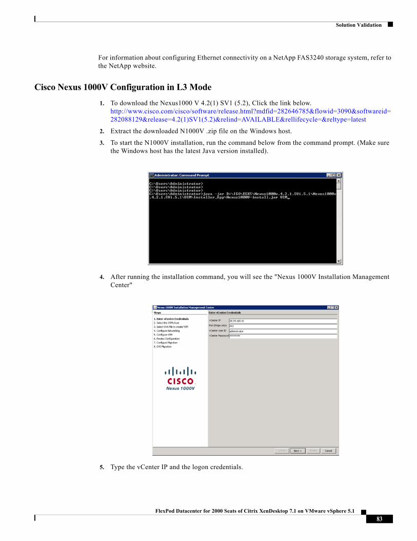
Solution Validation
For information about configuring Ethernet connectivity on a NetApp FAS3240 storage system, refer to the NetApp website.
Cisco Nexus 1000V Configuration in L3 Mode
1. To download the Nexus1000 V 4.2(1) SV1 (5.2), Click the link below. http://www.cisco.com/cisco/software/release.html?mdfid=282646785&flowid=3090&softwareid=282088129&release=4.2(1)SV1(5.2)&relind=AVAILABLE&rellifecycle=&reltype=latest
2. Extract the downloaded N1000V .zip file on the Windows host.
3. To start the N1000V installation, run the command below from the command prompt. (Make sure the Windows host has the latest Java version installed).
4. After running the installation command, you will see the "Nexus 1000V Installation Management Center"
5. Type the vCenter IP and the logon credentials.
83FlexPod Datacenter for 2000 Seats of Citrix XenDesktop 7.1 on VMware vSphere 5.1
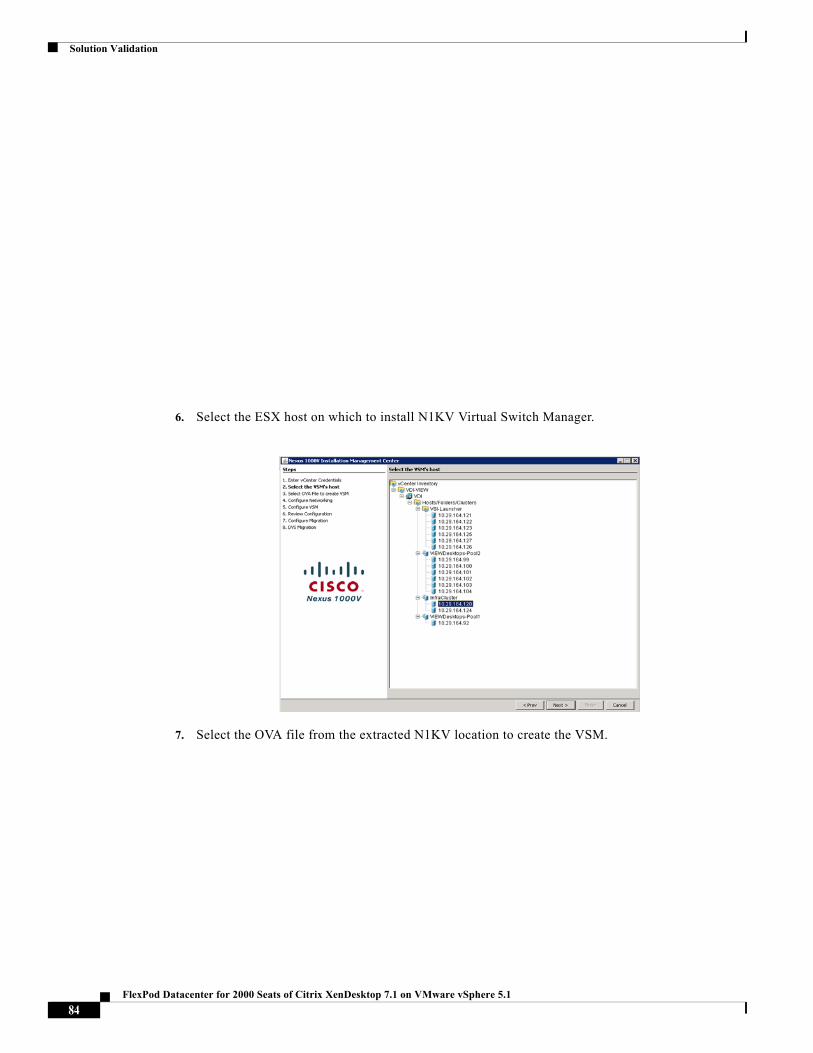
Solution Validation
6. Select the ESX host on which to install N1KV Virtual Switch Manager.
7. Select the OVA file from the extracted N1KV location to create the VSM.
84FlexPod Datacenter for 2000 Seats of Citrix XenDesktop 7.1 on VMware vSphere 5.1
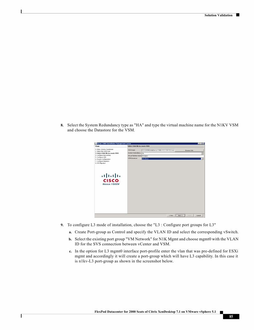
Solution Validation
8. Select the System Redundancy type as "HA" and type the virtual machine name for the N1KV VSM and choose the Datastore for the VSM.
9. To configure L3 mode of installation, choose the "L3 : Configure port groups for L3"
a. Create Port-group as Control and specify the VLAN ID and select the corresponding vSwitch.
b. Select the existing port group "VM Network" for N1K Mgmt and choose mgmt0 with the VLAN ID for the SVS connection between vCenter and VSM.
c. In the option for L3 mgmt0 interface port-profile enter the vlan that was pre-defined for ESXi mgmt and accordingly it will create a port-group which will have L3 capability. In this case it is n1kv-L3 port-group as shown in the screenshot below.
85FlexPod Datacenter for 2000 Seats of Citrix XenDesktop 7.1 on VMware vSphere 5.1
Solution Validation
To Configure VSM, Type the Switch Name and Enter the admin password for the VSM. Type the IP address, subnet mask, Gateway, Domain ID and select the SVS datacenter Name and Type the vSwitch0 Native vlan ID. (Make sure the Native VLAN ID specified should match the Native VLAN ID of Cisco Unified Computing System and Cisco Nexus 5k)
Note If there are multiple instances of N1KV VSM that need to be installed, make sure they are configured with different Domain IDs.
86FlexPod Datacenter for 2000 Seats of Citrix XenDesktop 7.1 on VMware vSphere 5.1
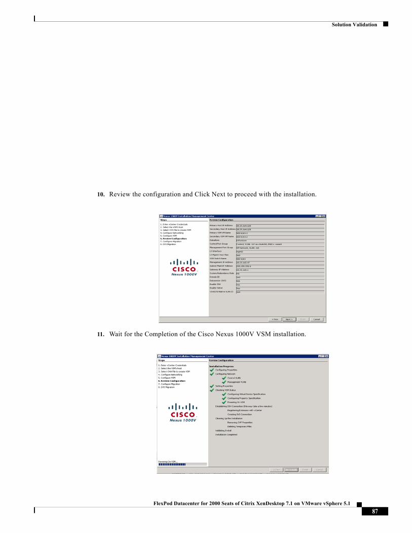
Solution Validation
10. Review the configuration and Click Next to proceed with the installation.
11. Wait for the Completion of the Cisco Nexus 1000V VSM installation.
87FlexPod Datacenter for 2000 Seats of Citrix XenDesktop 7.1 on VMware vSphere 5.1
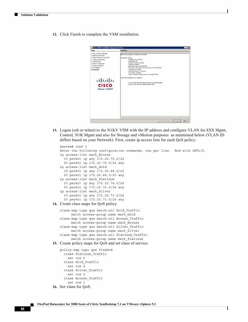
Solution Validation
12. Click Finish to complete the VSM installation.
13. Logon (ssh or telnet) to the N1KV VSM with the IP address and configure VLAN for ESX Mgmt, Control, N1K Mgmt and also for Storage and vMotion purposes as mentioned below (VLAN ID differs based on your Network). First, create ip access lists for each QoS policy:
xenvsm# conf tEnter the following configuration commands, one per line. End with CNTL/Z.ip access-list mark_Bronze 10 permit ip any 172.20.75.0/24 20 permit ip 172.20.75.0/24 anyip access-list mark_Gold 10 permit ip any 172.20.48.0/20 20 permit ip 172.20.48.0/20 anyip access-list mark_Platinum 10 permit ip any 172.20.74.0/24 20 permit ip 172.20.74.0/24 anyip access-list mark_Silver 10 permit ip any 172.20.73.0/24 20 permit ip 172.20.73.0/24 any
14. Create class maps for QoS policy.
class-map type qos match-all Gold_Traffic match access-group name mark_Goldclass-map type qos match-all Bronze_Traffic match access-group name mark_Bronzeclass-map type qos match-all Silver_Traffic match access-group name mark_Silverclass-map type qos match-all Platinum_Traffic match access-group name mark_Platinum
15. Create policy maps for QoS and set class of service.
policy-map type qos FlexPod class Platinum_Traffic set cos 5 class Gold_Traffic set cos 4 class Silver_Traffic set cos 2 class Bronze_Traffic set cos 1
16. Set vlans for QoS.
88FlexPod Datacenter for 2000 Seats of Citrix XenDesktop 7.1 on VMware vSphere 5.1
Solution Validation
vlan 1,6,3048,3073-3075vlan 6 name Native-VLANvlan 3048 name VM-Networkvlan 3073 name IB-MGMT-VLANvlan 3074 name Storage-VLANvlan 3075 name vMotion-VLAN
17. Create port profile for system uplinks and vethernet port groups. Note: There are existing port profiles created during the install. Do not modify or delete these port profiles.
port-profile type ethernet system-uplink vmware port-group switchport mode trunk switchport trunk native vlan 6 switchport trunk allowed vlan 3048,3073-3075 system mtu 9000 channel-group auto mode on mac-pinning no shutdown system vlan 3048,3073-3075 state enabledport-profile type vethernet IB-MGMT-VLAN vmware port-group switchport mode access switchport access vlan 3073 service-policy type qos input FlexPod no shutdown system vlan 3073 max-ports 254 state enabledport-profile type vethernet Storage-VLAN vmware port-group switchport mode access switchport access vlan 3074 service-policy type qos input FlexPod no shutdown system vlan 3074 state enabledport-profile type vethernet vMotion-VLAN vmware port-group switchport mode access switchport access vlan 3075 service-policy type qos input FlexPod no shutdown system vlan 3075 state enabledport-profile type vethernet VM-Network vmware port-group port-binding static auto expand switchport mode access switchport access vlan 3048 service-policy type qos input FlexPod no shutdown system vlan 3048 state enabledport-profile type vethernet n1k-L3 capability l3control vmware port-group switchport mode access switchport access vlan 3073 service-policy type qos input FlexPod
89FlexPod Datacenter for 2000 Seats of Citrix XenDesktop 7.1 on VMware vSphere 5.1
Solution Validation
no shutdown system vlan 3073 state enabled
18. Set the MTU size to 9000 on the Virtual Ethernet Modules.
interface port-channel1 inherit port-profile system-uplink vem 3 mtu 9000interface port-channel2 inherit port-profile system-uplink vem 5 mtu 9000interface port-channel3 inherit port-profile system-uplink vem 6 mtu 9000interface port-channel4 inherit port-profile system-uplink vem 4 mtu 9000interface port-channel5 inherit port-profile system-uplink vem 7 mtu 9000interface port-channel6 inherit port-profile system-uplink vem 8 mtu 9000interface port-channel7 inherit port-profile system-uplink vem 9 mtu 9000interface port-channel8 inherit port-profile system-uplink vem 10 mtu 9000interface port-channel9 inherit port-profile system-uplink vem 12 mtu 9000interface port-channel10 inherit port-profile system-uplink vem 11 mtu 9000interface port-channel11 inherit port-profile system-uplink vem 13 mtu 9000
interface port-channel12 inherit port-profile system-uplink vem 14 mtu 9000interface port-channel13 inherit port-profile system-uplink vem 15 mtu 9000interface port-channel14 inherit port-profile system-uplink vem 17 mtu 9000interface port-channel15 inherit port-profile system-uplink
90FlexPod Datacenter for 2000 Seats of Citrix XenDesktop 7.1 on VMware vSphere 5.1
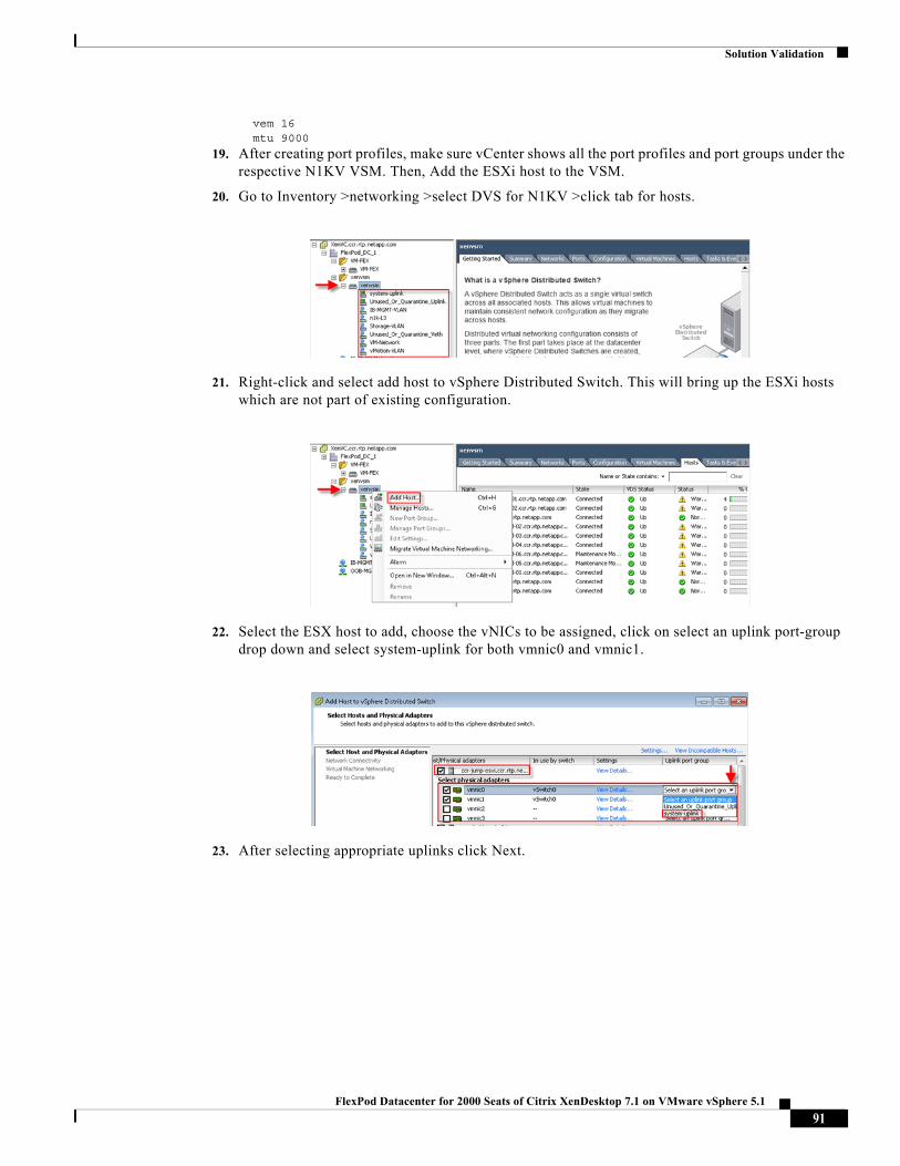
Solution Validation
vem 16 mtu 9000
19. After creating port profiles, make sure vCenter shows all the port profiles and port groups under the respective N1KV VSM. Then, Add the ESXi host to the VSM.
20. Go to Inventory >networking >select DVS for N1KV >click tab for hosts.
21. Right-click and select add host to vSphere Distributed Switch. This will bring up the ESXi hosts which are not part of existing configuration.
22. Select the ESX host to add, choose the vNICs to be assigned, click on select an uplink port-group drop down and select system-uplink for both vmnic0 and vmnic1.
23. After selecting appropriate uplinks click Next.
91FlexPod Datacenter for 2000 Seats of Citrix XenDesktop 7.1 on VMware vSphere 5.1
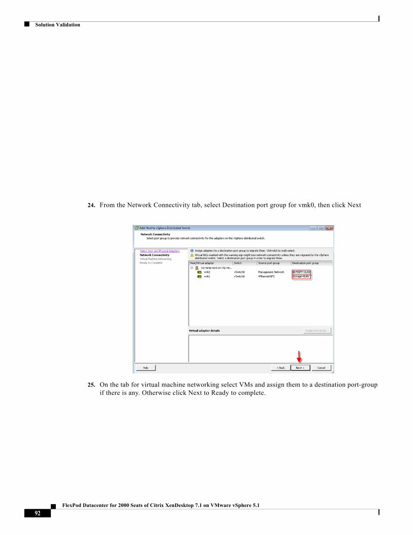
Solution Validation
24. From the Network Connectivity tab, select Destination port group for vmk0, then click Next
25. On the tab for virtual machine networking select VMs and assign them to a destination port-group if there is any. Otherwise click Next to Ready to complete.
92FlexPod Datacenter for 2000 Seats of Citrix XenDesktop 7.1 on VMware vSphere 5.1
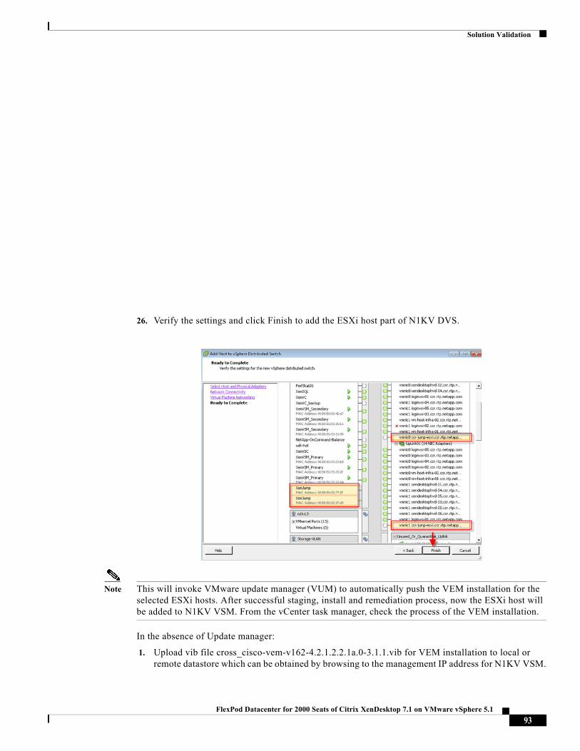
Solution Validation
26. Verify the settings and click Finish to add the ESXi host part of N1KV DVS.
Note This will invoke VMware update manager (VUM) to automatically push the VEM installation for the selected ESXi hosts. After successful staging, install and remediation process, now the ESXi host will be added to N1KV VSM. From the vCenter task manager, check the process of the VEM installation.
In the absence of Update manager:
1. Upload vib file cross_cisco-vem-v162-4.2.1.2.2.1a.0-3.1.1.vib for VEM installation to local or remote datastore which can be obtained by browsing to the management IP address for N1KV VSM.
93FlexPod Datacenter for 2000 Seats of Citrix XenDesktop 7.1 on VMware vSphere 5.1
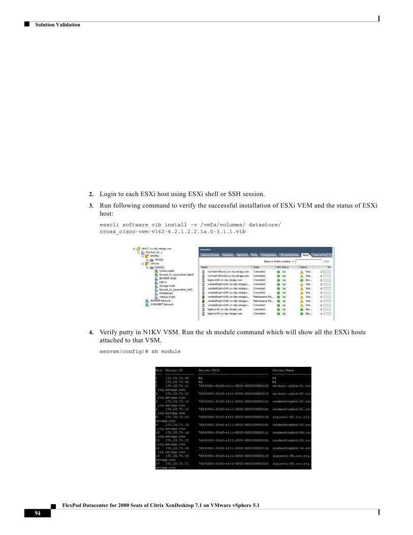
Solution Validation
2. Login to each ESXi host using ESXi shell or SSH session.
3. Run following command to verify the successful installation of ESXi VEM and the status of ESXi host:
esxcli software vib install -v /vmfs/volumes/ datastore/ cross_cisco-vem-v162-4.2.1.2.2.1a.0-3.1.1.vib
4. Verify putty in N1KV VSM. Run the sh module command which will show all the ESXi hosts attached to that VSM.
xenvsm(config)# sh module
94FlexPod Datacenter for 2000 Seats of Citrix XenDesktop 7.1 on VMware vSphere 5.1
Solution Validation
SAN Configuration
The same pair of Cisco Nexus 5548UP switches were used in the configuration to connect between the FCoE ports on the NetApp FAS3240 and the FCoE ports of the Cisco UCS 6248 Fabric Interconnects.
Boot from SAN Benefits
Booting from SAN is another key feature which helps in moving towards stateless computing in which there is no static binding between a physical server and the OS/applications it is tasked to run. The OS is installed on a SAN LUN and boot from SAN policy is applied to the service profile template or the service profile. If the service profile were to be moved to another server, the pwwn of the HBAs and the Boot from SAN (BFS) policy also moves along with it. The new server now takes the same exact character of the old server, providing the true unique stateless nature of the Cisco UCS Blade Server.
The key benefits of booting from the network:
• Reduce Server Footprints: Boot from SAN alleviates the necessity for each server to have its own direct-attached disk, eliminating internal disks as a potential point of failure. Thin diskless servers also take up less facility space, require less power, and are generally less expensive because they have fewer hardware components.
• Disaster and Server Failure Recovery: All the boot information and production data stored on a local SAN can be replicated to a SAN at a remote disaster recovery site. If a disaster destroys functionality of the servers at the primary site, the remote site can take over with minimal downtime.
• Recovery from server failures is simplified in a SAN environment. With the help of snapshots, mirrors of a failed server can be recovered quickly by booting from the original copy of its image. As a result, boot from SAN can greatly reduce the time required for server recovery.
• High Availability: A typical data center is highly redundant in nature - redundant paths, redundant disks and redundant storage controllers. When operating system images are stored on disks in the SAN, it supports high availability and eliminates the potential for mechanical failure of a local disk.
• Rapid Redeployment: Businesses that experience temporary high production workloads can take advantage of SAN technologies to clone the boot image and distribute the image to multiple servers for rapid deployment. Such servers may only need to be in production for hours or days and can be readily removed when the production need has been met. Highly efficient deployment of boot images makes temporary server usage a cost effective endeavor.
• Centralized Image Management: When operating system images are stored on networked disks, all upgrades and fixes can be managed at a centralized location. Changes made to disks in a storage array are readily accessible by each server.
• With Boot from SAN, the image resides on a SAN LUN and the server communicates with the SAN through a host bus adapter (HBA). The HBAs BIOS contain the instructions that enable the server to find the boot disk. All FCoE-capable Converged Network Adapter (CNA) cards supported on Cisco UCS B-Series Blade Servers support Boot from SAN.
• After power on self-test (POST), the server hardware component fetches the boot device that is designated as the boot device in the hardware BOIS settings. When the hardware detects the boot device, it follows the regular boot process.
Configuring Boot from SAN Overview
There are three distinct phases during the configuration of Boot from SAN. The high level procedures are:
95FlexPod Datacenter for 2000 Seats of Citrix XenDesktop 7.1 on VMware vSphere 5.1
Solution Validation
• SAN configuration on the Nexus 5548UPs
• Storage array host initiator configuration
• Cisco UCS configuration of Boot from SAN policy in the service profile
In each of the following sections, each high-level phase will be discussed.
SAN Configuration on Cisco Nexus 5548UP
The FCoE and NPIV features have to be turned on in the Nexus 5500 series switch. Make sure you have 10 GB SFP+ modules connected to the Cisco Nexus 5548UP ports. The port mode is set to AUTO as well as the speed is set to AUTO. Rate mode is "dedicated" and when everything is configured correctly you should see something like the output below on a Nexus 5500 series switch for a given port (for example, Fc1/17).
Note A Cisco Nexus 5500 series switch supports multiple VSAN configurations. Two VSANs were deployed in this study: VSAN 500 on Fabric A and VSAN 501 on Fabric B.
Cisco Fabric Manager can also be used to get a overall picture of the SAN configuration and zoning information. As discussed earlier, the SAN zoning is done upfront for all the pwwns of the initiators with the NetApp FAS3240 target pwwns.
The steps to prepare the Nexus 5548UPs for boot from SAN follow. We show only the configuration on Fabric A. The same commands are used to configure the Cisco Nexus 5548UP for Fabric B, but are not shown here. The complete configuration for both Cisco Nexus 5548UP switches are contained in the Appendix to this document.
1. Enter configuration mode on each switch:
config t
2. Start by adding the npiv and fcoe features to both Cisco Nexus 5548UP switches:
feature npivfeature fcoe
3. Verify that the feature is enabled on both switches:
show feature | grep npiv npiv 1 enabled
show feature | grep fcoe fcoe 1 enabled fcoe-npv 1 disabled
4. Configure the FCoE VLAN on both switches (500 for Fabric A and 501 for Fabric B)
vlan 500 fcoe vsan 500 name FCoE_Fabric_A
5. Configure the vsan database(500 for Fabric A and 501 for Fabric B)
vsan database vsan 500 name "Fabric_A"
6. Configure the port channel for fcoe traffic (vlan 500 for Fabric A and 501 for Fabric B)
interface port-channel500 description stl6248-I5-2-cluster-A:FCoE switchport mode trunk switchport trunk native vlan 6 switchport trunk allowed vlan 500 spanning-tree port type edge trunk
7. Configure the virtual fiber channel interfaces used by fcoe (vlan 500 for Fabric A and 501 for Fabric B)
96FlexPod Datacenter for 2000 Seats of Citrix XenDesktop 7.1 on VMware vSphere 5.1
Solution Validation
interface vfc1 bind interface Ethernet1/1 switchport trunk allowed vsan 500 switchport description ccr-cmode-1-01:3a no shutdown
interface vfc2 bind interface Ethernet1/2 switchport trunk allowed vsan 500 switchport description ccr-cmode-1-02:3a no shutdown
interface vfc3 bind interface Ethernet1/3 switchport trunk allowed vsan 500 switchport description ccr-cmode-1-03:3a no shutdown
interface vfc4 bind interface Ethernet1/4 switchport trunk allowed vsan 500 switchport description ccr-cmode-1-04:3a no shutdown interface vfc500 bind interface port-channel500 switchport trunk allowed vsan 500 switchport description stl6248-I5-2-cluster-A:FCoE no shutdown
8. Configure the vsan database with the virtual fiber channel ports created above. (vlan 500 for Fabric A and 501 for Fabric B)
vsan database vsan 500 interface vfc1 vsan 500 interface vfc2 vsan 500 interface vfc3 vsan 500 interface vfc4 vsan 500 interface vfc500
9. Configure the ethernet interfaces used for fcoe traffic. (vlan 500 for Fabric A and 501 for Fabric B)
interface Ethernet1/1 description ccr-cmode-1-01:e3a switchport mode trunk switchport trunk native vlan 6 switchport trunk allowed vlan 500 spanning-tree port type edge trunk
interface Ethernet1/2 description ccr-cmode-1-02:e3a switchport mode trunk switchport trunk native vlan 6 switchport trunk allowed vlan 500 spanning-tree port type edge trunk
interface Ethernet1/3 description ccr-cmode-1-03:e3a switchport mode trunk switchport trunk native vlan 6 switchport trunk allowed vlan 500 spanning-tree port type edge trunk
interface Ethernet1/4 description ccr-cmode-1-04:e3a switchport mode trunk switchport trunk native vlan 6
97FlexPod Datacenter for 2000 Seats of Citrix XenDesktop 7.1 on VMware vSphere 5.1
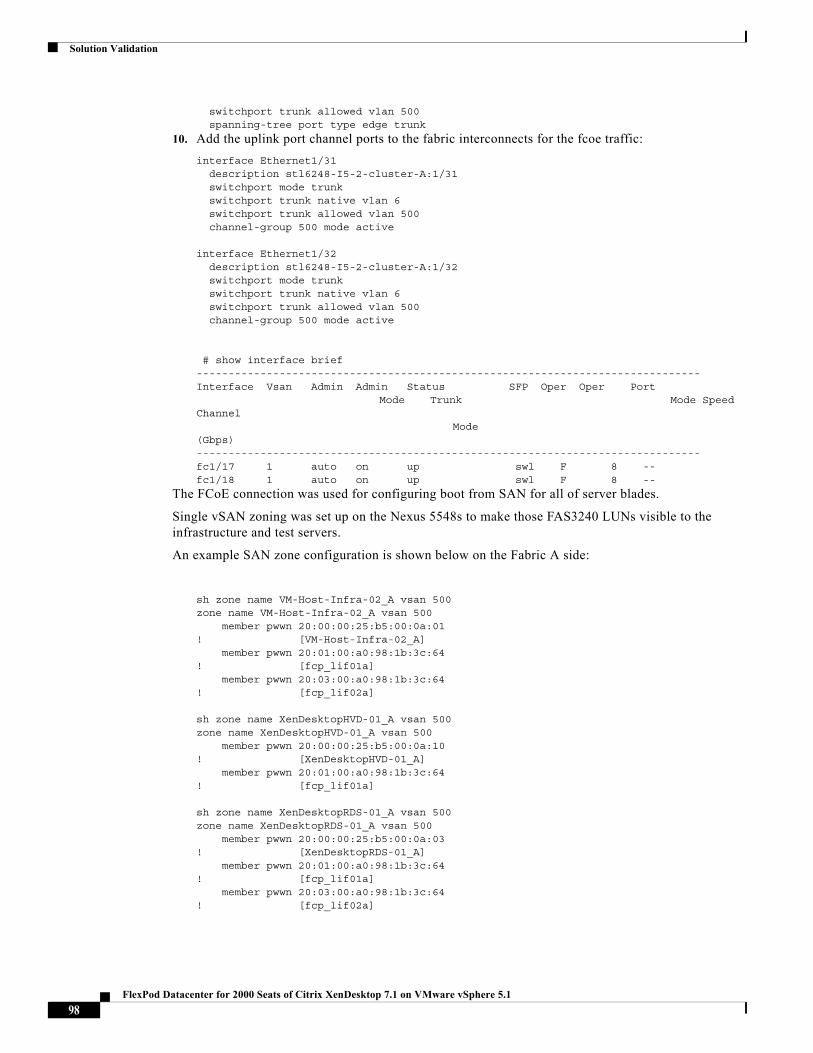
Solution Validation
switchport trunk allowed vlan 500 spanning-tree port type edge trunk
10. Add the uplink port channel ports to the fabric interconnects for the fcoe traffic:
interface Ethernet1/31 description stl6248-I5-2-cluster-A:1/31 switchport mode trunk switchport trunk native vlan 6 switchport trunk allowed vlan 500 channel-group 500 mode active
interface Ethernet1/32 description stl6248-I5-2-cluster-A:1/32 switchport mode trunk switchport trunk native vlan 6 switchport trunk allowed vlan 500 channel-group 500 mode active
# show interface brief-------------------------------------------------------------------------------Interface Vsan Admin Admin Status SFP Oper Oper Port Mode Trunk Mode Speed Channel Mode (Gbps)-------------------------------------------------------------------------------fc1/17 1 auto on up swl F 8 --fc1/18 1 auto on up swl F 8 --
The FCoE connection was used for configuring boot from SAN for all of server blades.
Single vSAN zoning was set up on the Nexus 5548s to make those FAS3240 LUNs visible to the infrastructure and test servers.
An example SAN zone configuration is shown below on the Fabric A side:
sh zone name VM-Host-Infra-02_A vsan 500zone name VM-Host-Infra-02_A vsan 500 member pwwn 20:00:00:25:b5:00:0a:01! [VM-Host-Infra-02_A] member pwwn 20:01:00:a0:98:1b:3c:64! [fcp_lif01a] member pwwn 20:03:00:a0:98:1b:3c:64! [fcp_lif02a]
sh zone name XenDesktopHVD-01_A vsan 500zone name XenDesktopHVD-01_A vsan 500 member pwwn 20:00:00:25:b5:00:0a:10! [XenDesktopHVD-01_A] member pwwn 20:01:00:a0:98:1b:3c:64! [fcp_lif01a]
sh zone name XenDesktopRDS-01_A vsan 500zone name XenDesktopRDS-01_A vsan 500 member pwwn 20:00:00:25:b5:00:0a:03! [XenDesktopRDS-01_A] member pwwn 20:01:00:a0:98:1b:3c:64! [fcp_lif01a] member pwwn 20:03:00:a0:98:1b:3c:64! [fcp_lif02a]
98FlexPod Datacenter for 2000 Seats of Citrix XenDesktop 7.1 on VMware vSphere 5.1
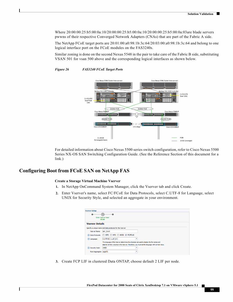
Solution Validation
Where 20:00:00:25:b5:00:0a:10/20:00:00:25:b5:00:0a:10/20:00:00:25:b5:00:0a:03are blade servers pwwns of their respective Converged Network Adapters (CNAs) that are part of the Fabric A side.
The NetApp FCoE target ports are 20:01:00:a0:98:1b:3c:64/20:03:00:a0:98:1b:3c:64 and belong to one logical interface port on the FCoE modules on the FAS3240s.
Similar zoning is done on the second Nexus 5548 in the pair to take care of the Fabric B side, substituting VSAN 501 for vsan 500 above and the corresponding logical interfaces as shown below.
Figure 26 FAS3240 FCoE Target Ports
For detailed information about Cisco Nexus 5500 series switch configuration, refer to Cisco Nexus 5500 Series NX-OS SAN Switching Configuration Guide. (See the Reference Section of this document for a link.)
Configuring Boot from FCoE SAN on NetApp FAS
Create a Storage Virtual Machine Vserver
1. In NetApp OnCommand System Manager, click the Vserver tab and click Create.
2. Enter Vserver's name, select FC/FCoE for Data Protocols, select C.UTF-8 for Language, select UNIX for Security Style, and selected an aggregate in your environment.
3. Create FCP LIF in clustered Data ONTAP, choose default 2 LIF per node.
99FlexPod Datacenter for 2000 Seats of Citrix XenDesktop 7.1 on VMware vSphere 5.1
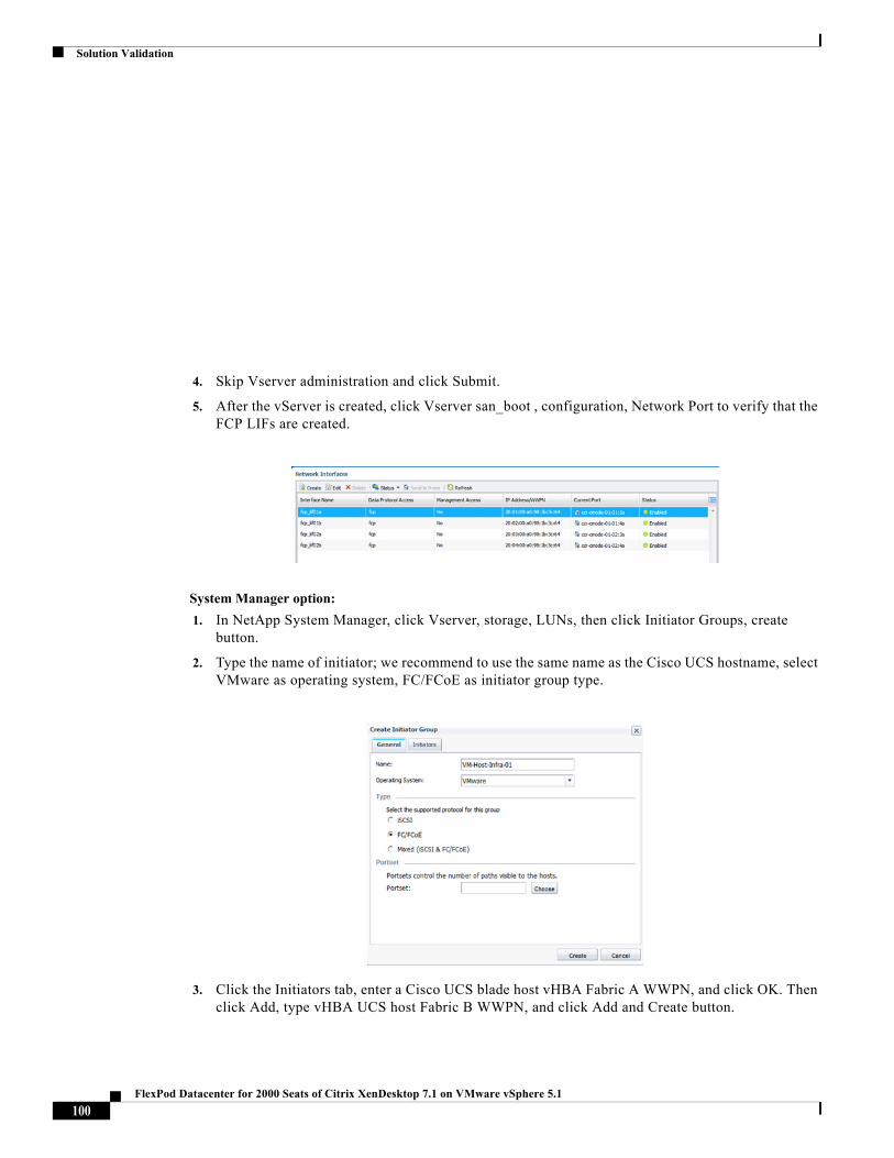
Solution Validation
4. Skip Vserver administration and click Submit.
5. After the vServer is created, click Vserver san_boot , configuration, Network Port to verify that the FCP LIFs are created.
System Manager option:
1. In NetApp System Manager, click Vserver, storage, LUNs, then click Initiator Groups, create button.
2. Type the name of initiator; we recommend to use the same name as the Cisco UCS hostname, select VMware as operating system, FC/FCoE as initiator group type.
3. Click the Initiators tab, enter a Cisco UCS blade host vHBA Fabric A WWPN, and click OK. Then click Add, type vHBA UCS host Fabric B WWPN, and click Add and Create button.
100FlexPod Datacenter for 2000 Seats of Citrix XenDesktop 7.1 on VMware vSphere 5.1
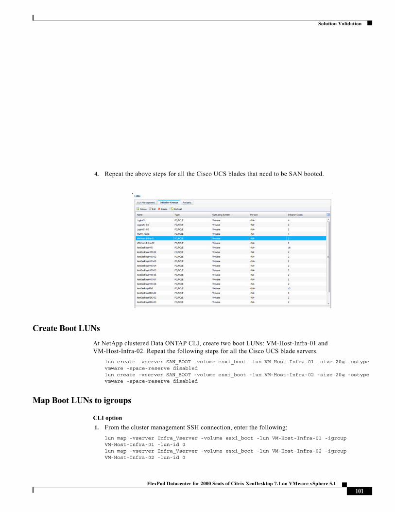
Solution Validation
4. Repeat the above steps for all the Cisco UCS blades that need to be SAN booted.
Create Boot LUNs
At NetApp clustered Data ONTAP CLI, create two boot LUNs: VM-Host-Infra-01 and VM-Host-Infra-02. Repeat the following steps for all the Cisco UCS blade servers.
lun create -vserver SAN_BOOT -volume esxi_boot -lun VM-Host-Infra-01 -size 20g -ostype vmware -space-reserve disabled lun create -vserver SAN_BOOT -volume esxi_boot -lun VM-Host-Infra-02 -size 20g -ostype vmware -space-reserve disabled
Map Boot LUNs to igroups
CLI option
1. From the cluster management SSH connection, enter the following:
lun map -vserver Infra_Vserver -volume esxi_boot -lun VM-Host-Infra-01 -igroup VM-Host-Infra-01 -lun-id 0lun map -vserver Infra_Vserver -volume esxi_boot -lun VM-Host-Infra-02 -igroup VM-Host-Infra-02 -lun-id 0
101FlexPod Datacenter for 2000 Seats of Citrix XenDesktop 7.1 on VMware vSphere 5.1
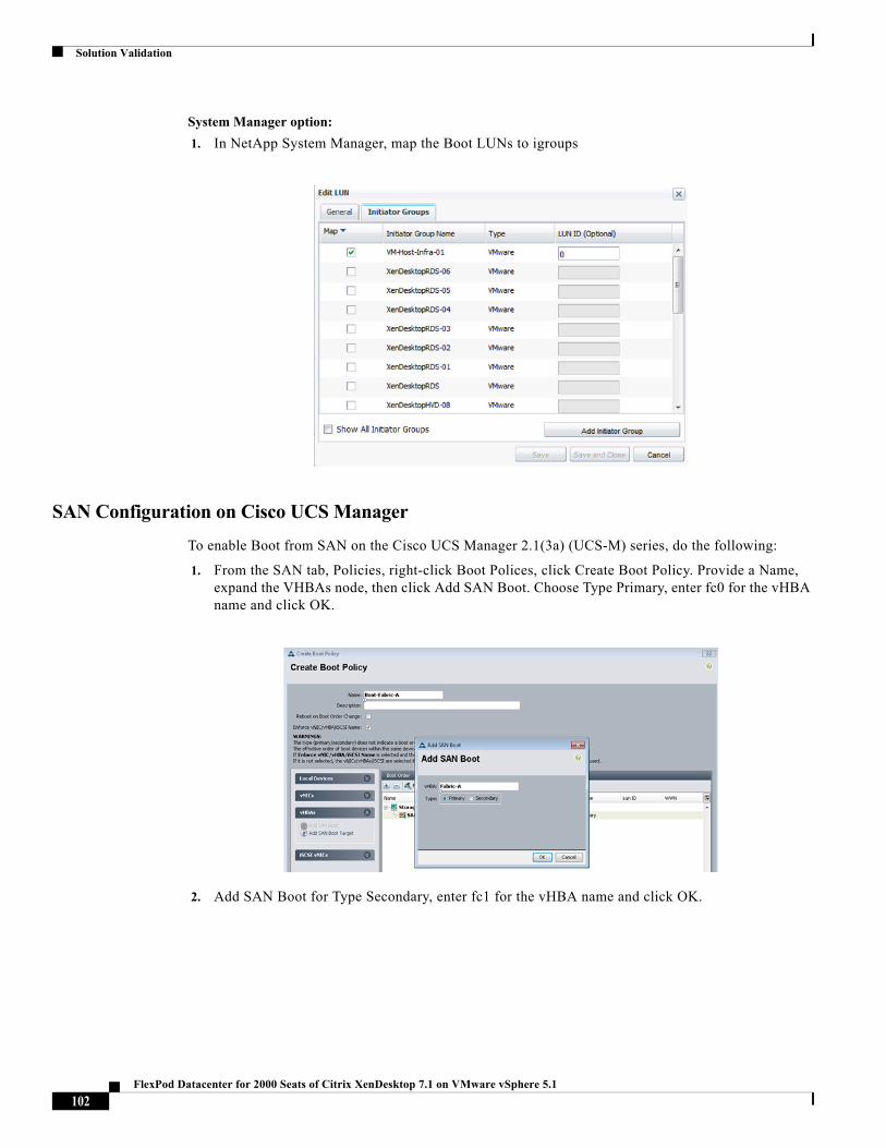
Solution Validation
System Manager option:
1. In NetApp System Manager, map the Boot LUNs to igroups
SAN Configuration on Cisco UCS Manager
To enable Boot from SAN on the Cisco UCS Manager 2.1(3a) (UCS-M) series, do the following:
1. From the SAN tab, Policies, right-click Boot Polices, click Create Boot Policy. Provide a Name, expand the VHBAs node, then click Add SAN Boot. Choose Type Primary, enter fc0 for the vHBA name and click OK.
2. Add SAN Boot for Type Secondary, enter fc1 for the vHBA name and click OK.
102FlexPod Datacenter for 2000 Seats of Citrix XenDesktop 7.1 on VMware vSphere 5.1
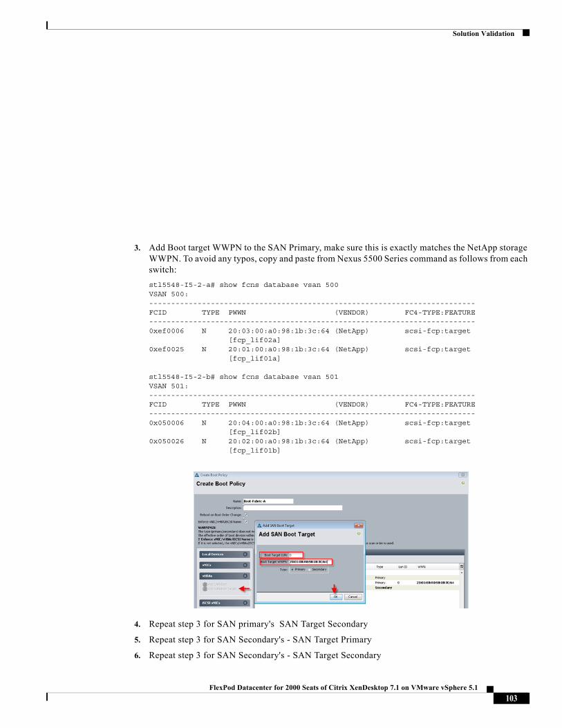
Solution Validation
3. Add Boot target WWPN to the SAN Primary, make sure this is exactly matches the NetApp storage WWPN. To avoid any typos, copy and paste from Nexus 5500 Series command as follows from each switch:
stl5548-I5-2-a# show fcns database vsan 500VSAN 500:--------------------------------------------------------------------------FCID TYPE PWWN (VENDOR) FC4-TYPE:FEATURE--------------------------------------------------------------------------0xef0006 N 20:03:00:a0:98:1b:3c:64 (NetApp) scsi-fcp:target [fcp_lif02a]0xef0025 N 20:01:00:a0:98:1b:3c:64 (NetApp) scsi-fcp:target [fcp_lif01a]
stl5548-I5-2-b# show fcns database vsan 501VSAN 501:--------------------------------------------------------------------------FCID TYPE PWWN (VENDOR) FC4-TYPE:FEATURE--------------------------------------------------------------------------0x050006 N 20:04:00:a0:98:1b:3c:64 (NetApp) scsi-fcp:target [fcp_lif02b]0x050026 N 20:02:00:a0:98:1b:3c:64 (NetApp) scsi-fcp:target [fcp_lif01b]
4. Repeat step 3 for SAN primary's SAN Target Secondary
5. Repeat step 3 for SAN Secondary's - SAN Target Primary
6. Repeat step 3 for SAN Secondary's - SAN Target Secondary
103FlexPod Datacenter for 2000 Seats of Citrix XenDesktop 7.1 on VMware vSphere 5.1
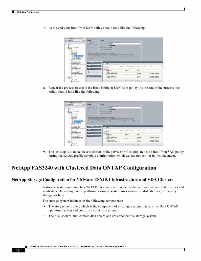
Solution Validation
7. At the end your Boot from SAN policy should look like the following:
8. Repeat the process to create the Boot-Fabric-B SAN Boot policy. At the end of the process, the policy should look like the following:
9. The last step is to make the association of the service profile template to the Boot from SAN policy during the service profile template configuration which we covered earlier in this document.
NetApp FAS3240 with Clustered Data ONTAP Configuration
NetApp Storage Configuration for VMware ESXi 5.1 Infrastructure and VDA Clusters
A storage system running Data ONTAP has a main unit, which is the hardware device that receives and sends data. Depending on the platform, a storage system uses storage on disk shelves, third-party storage, or both.
The storage system includes of the following components:
• The storage controller, which is the component of a storage system that runs the Data ONTAP operating system and controls its disk subsystem.
• The disk shelves, that contain disk drives and are attached to a storage system.
104FlexPod Datacenter for 2000 Seats of Citrix XenDesktop 7.1 on VMware vSphere 5.1
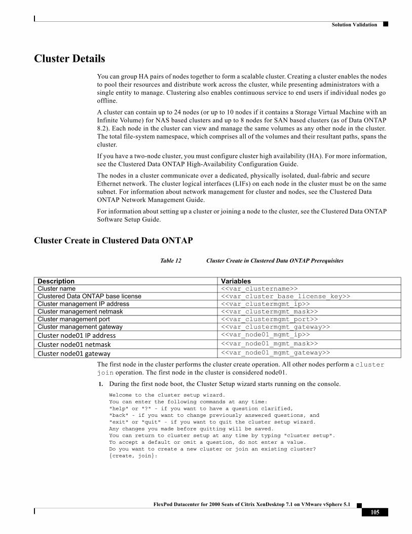
Solution Validation
Cluster Details
You can group HA pairs of nodes together to form a scalable cluster. Creating a cluster enables the nodes to pool their resources and distribute work across the cluster, while presenting administrators with a single entity to manage. Clustering also enables continuous service to end users if individual nodes go offline.
A cluster can contain up to 24 nodes (or up to 10 nodes if it contains a Storage Virtual Machine with an Infinite Volume) for NAS based clusters and up to 8 nodes for SAN based clusters (as of Data ONTAP 8.2). Each node in the cluster can view and manage the same volumes as any other node in the cluster. The total file-system namespace, which comprises all of the volumes and their resultant paths, spans the cluster.
If you have a two-node cluster, you must configure cluster high availability (HA). For more information, see the Clustered Data ONTAP High-Availability Configuration Guide.
The nodes in a cluster communicate over a dedicated, physically isolated, dual-fabric and secure Ethernet network. The cluster logical interfaces (LIFs) on each node in the cluster must be on the same subnet. For information about network management for cluster and nodes, see the Clustered Data ONTAP Network Management Guide.
For information about setting up a cluster or joining a node to the cluster, see the Clustered Data ONTAP Software Setup Guide.
Cluster Create in Clustered Data ONTAP
Table 12 Cluster Create in Clustered Data ONTAP Prerequisites
The first node in the cluster performs the cluster create operation. All other nodes perform a cluster join operation. The first node in the cluster is considered node01.
1. During the first node boot, the Cluster Setup wizard starts running on the console.
Welcome to the cluster setup wizard.You can enter the following commands at any time:"help" or "?" - if you want to have a question clarified,"back" - if you want to change previously answered questions, and"exit" or "quit" - if you want to quit the cluster setup wizard.Any changes you made before quitting will be saved.You can return to cluster setup at any time by typing "cluster setup".To accept a default or omit a question, do not enter a value.Do you want to create a new cluster or join an existing cluster?{create, join}:
Description VariablesCluster name <<var_clustername>>Clustered Data ONTAP base license <<var_cluster_base_license_key>>Cluster management IP address <<var_clustermgmt_ip>>Cluster management netmask <<var_clustermgmt_mask>>Cluster management port <<var_clustermgmt_port>>Cluster management gateway <<var_clustermgmt_gateway>>Cluster node01 IP address <<var_node01_mgmt_ip>>
Cluster node01 netmask <<var_node01_mgmt_mask>>
Cluster node01 gateway <<var_node01_mgmt_gateway>>
105FlexPod Datacenter for 2000 Seats of Citrix XenDesktop 7.1 on VMware vSphere 5.1
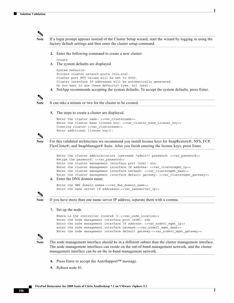
Solution Validation
Note If a login prompt appears instead of the Cluster Setup wizard, start the wizard by logging in using the factory default settings and then enter the cluster setup command.
2. Enter the following command to create a new cluster:
create
3. The system defaults are displayed.
System Defaults:Private cluster network ports [e1a,e2a].Cluster port MTU values will be set to 9000.Cluster interface IP addresses will be automatically generated.Do you want to use these defaults? {yes, no} [yes]:
4. NetApp recommends accepting the system defaults. To accept the system defaults, press Enter.
Note It can take a minute or two for the cluster to be created.
5. The steps to create a cluster are displayed.
Enter the cluster name: <<var_clustername>>Enter the cluster base license key: <<var_cluster_base_license_key>>Creating cluster <<var_clustername>>Enter additional license key[]:
Note For this validated architecture we recommend you install license keys for SnapRestore®, NFS, FCP, FlexClone®, and SnapManager® Suite. After you finish entering the license keys, press Enter.
Enter the cluster administrators (username "admin") password: <<var_password>>Retype the password: <<var_password>>Enter the cluster management interface port [e0a]: e0aEnter the cluster management interface IP address: <<var_clustermgmt_ip>>Enter the cluster management interface netmask: <<var_clustermgmt_mask>>Enter the cluster management interface default gateway: <<var_clustermgmt_gateway>>
6. Enter the DNS domain name.
Enter the DNS domain names:<<var_dns_domain_name>>Enter the name server IP addresses:<<var_nameserver_ip>>
Note If you have more than one name server IP address, separate them with a comma.
7. Set up the node.
Where is the controller located []:<<var_node_location>>Enter the node management interface port [e0M]: e0bEnter the node management interface IP address: <<var_node01_mgmt_ip>>enter the node management interface netmask:<<var_node01_mgmt_mask>>Enter the node management interface default gateway:<<var_node01_mgmt_gateway>>
Note The node management interface should be in a different subnet than the cluster management interface. The node management interfaces can reside on the out-of-band management network, and the cluster management interface can be on the in-band management network.
8. Press Enter to accept the AutoSupport™ message.
9. Reboot node 01.
106FlexPod Datacenter for 2000 Seats of Citrix XenDesktop 7.1 on VMware vSphere 5.1
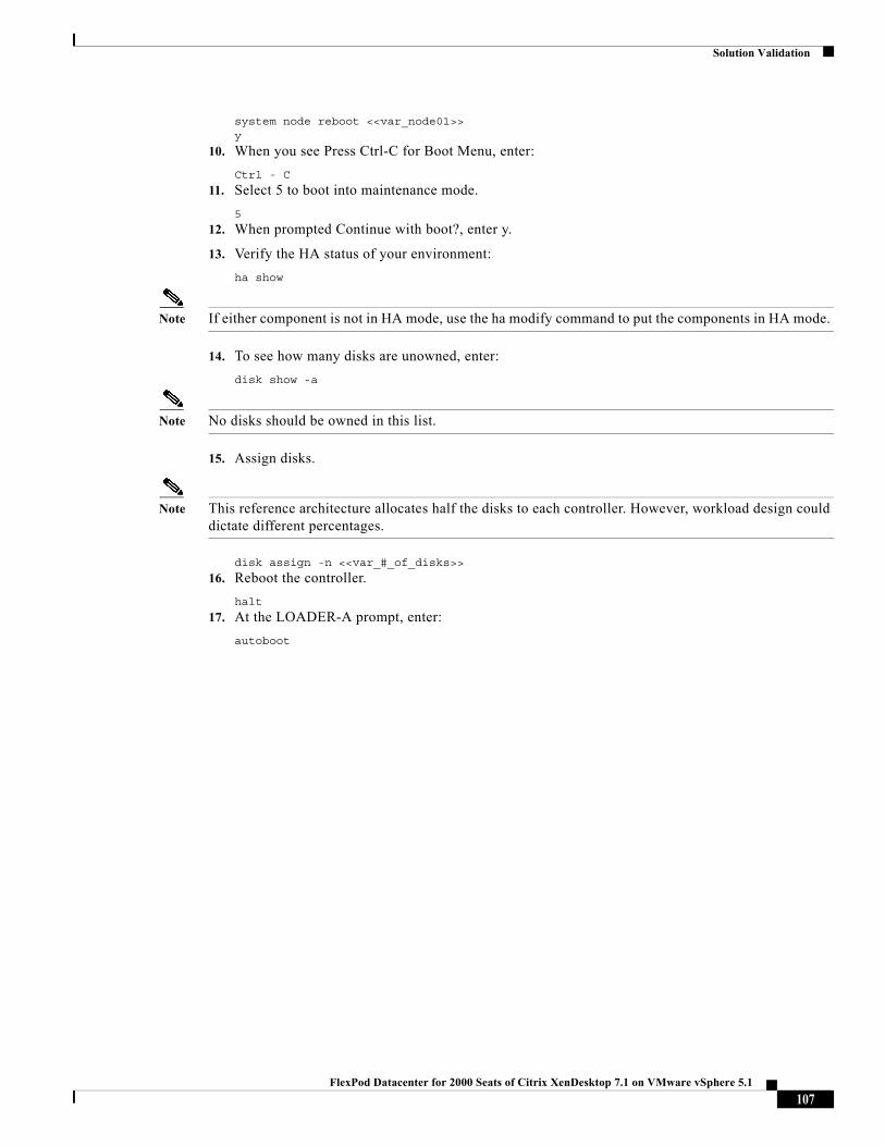
Solution Validation
system node reboot <<var_node01>>y
10. When you see Press Ctrl-C for Boot Menu, enter:
Ctrl - C
11. Select 5 to boot into maintenance mode.
5
12. When prompted Continue with boot?, enter y.
13. Verify the HA status of your environment:
ha show
Note If either component is not in HA mode, use the ha modify command to put the components in HA mode.
14. To see how many disks are unowned, enter:
disk show -a
Note No disks should be owned in this list.
15. Assign disks.
Note This reference architecture allocates half the disks to each controller. However, workload design could dictate different percentages.
disk assign -n <<var_#_of_disks>>
16. Reboot the controller.
halt
17. At the LOADER-A prompt, enter:
autoboot
107FlexPod Datacenter for 2000 Seats of Citrix XenDesktop 7.1 on VMware vSphere 5.1
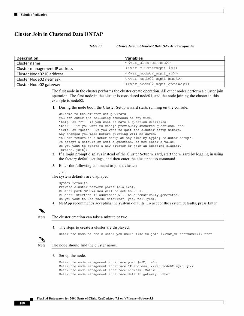
Solution Validation
Cluster Join in Clustered Data ONTAP
Table 13 Cluster Join in Clustered Data ONTAP Prerequisites
The first node in the cluster performs the cluster create operation. All other nodes perform a cluster join operation. The first node in the cluster is considered node01, and the node joining the cluster in this example is node02.
1. During the node boot, the Cluster Setup wizard starts running on the console.
Welcome to the cluster setup wizard.You can enter the following commands at any time:"help" or "?" - if you want to have a question clarified,"back" - if you want to change previously answered questions, and"exit" or "quit" - if you want to quit the cluster setup wizard.Any changes you made before quitting will be saved.You can return to cluster setup at any time by typing "cluster setup".To accept a default or omit a question, do not enter a value.Do you want to create a new cluster or join an existing cluster?{create, join}:
2. If a login prompt displays instead of the Cluster Setup wizard, start the wizard by logging in using the factory default settings, and then enter the cluster setup command.
3. Enter the following command to join a cluster:
join
The system defaults are displayed.
System Defaults:Private cluster network ports [e1a,e2a].Cluster port MTU values will be set to 9000.Cluster interface IP addresses will be automatically generated.Do you want to use these defaults? {yes, no} [yes]:
4. NetApp recommends accepting the system defaults. To accept the system defaults, press Enter.
Note The cluster creation can take a minute or two.
5. The steps to create a cluster are displayed.
Enter the name of the cluster you would like to join [<<var_clustername>>]:Enter
Note The node should find the cluster name.
6. Set up the node.
Enter the node management interface port [e0M]: e0bEnter the node management interface IP address: <<var_node02_mgmt_ip>>Enter the node management interface netmask: EnterEnter the node management interface default gateway: Enter
Description VariablesCluster name <<var_clustername>>
Cluster management IP address <<var_clustermgmt_ip>>
Cluster Node02 IP address <<var_node02_mgmt_ip>>
Cluster Node02 netmask <<var_node02_mgmt_mask>>
Cluster Node02 gateway <<var_node02_mgmt_gateway>>
108FlexPod Datacenter for 2000 Seats of Citrix XenDesktop 7.1 on VMware vSphere 5.1

Solution Validation
7. The node management interface should be in a subnet different from the cluster management interface. The node management interfaces can reside on the out-of-band management network, and the cluster management interface can be on the in-band management network.
8. Press Enter to accept the AutoSupport message.
9. Log in to the Cluster Interface with the admin user id and <<var_password>>.
10. Reboot node 02.
system node reboot <<var_node02>>y
11. When you see Press Ctrl-C for Boot Menu, enter:
Ctrl - C
12. Select 5 to boot into maintenance mode.
5
13. At the question, Continue with boot? enter:
y
14. To verify the HA status of your environment, enter:
Note If either component is not in HA mode, use the ha modify command to put the components in HA mode.
ha show
15. To see how many disks are unowned, enter:
disk show -a
16. Assign disks.
17. This reference architecture allocates half the disks to each controller. Workload design could dictate different percentages, however. Assign all remaining disks to node 02.
disk assign -n <<var_#_of_disks>>
18. Reboot the controller:
halt
19. At the LOADER-A prompt, enter:
autoboot
20. Press Ctrl-C for boot menu when prompted.
Ctrl-C
Login in to the Cluster
21. Open an SSH connection to cluster IP or host name and log in to the admin user with the password you provided earlier.
Table 14 shows the cluster details.
Table 14 Node Details
Cluster Name Node Name System Model Serial Number HA Partner Node Name
Data ONTAP Version
ccr-cmode-01 ccr-cmode-01-01 FAS3240 700000875853 ccr-cmode-01-02 8.2P4ccr-cmode-01 ccr-cmode-01-02 FAS3240 700000875877 ccr-cmode-01-01 8.2P4
109FlexPod Datacenter for 2000 Seats of Citrix XenDesktop 7.1 on VMware vSphere 5.1
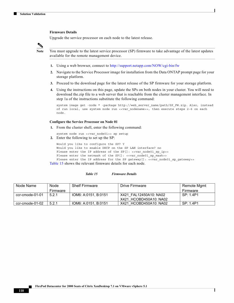
Solution Validation
Firmware Details
Upgrade the service processor on each node to the latest release.
Note You must upgrade to the latest service processor (SP) firmware to take advantage of the latest updates available for the remote management device.
1. Using a web browser, connect to http://support.netapp.com/NOW/cgi-bin/fw
2. Navigate to the Service Processor image for installation from the Data ONTAP prompt page for your storage platform.
3. Proceed to the download page for the latest release of the SP firmware for your storage platform.
4. Using the instructions on this page, update the SPs on both nodes in your cluster. You will need to download the.zip file to a web server that is reachable from the cluster management interface. In step 1a of the instructions substitute the following command:
system image get -node * -package http://web_server_name/path/SP_FW.zip. Also, instead of run local, use system node run <<var_nodename>>, then execute steps 2-6 on each node.
Configure the Service Processor on Node 01
1. From the cluster shell, enter the following command:
system node run <<var_node01>> sp setup
2. Enter the following to set up the SP:
Would you like to configure the SP? YWould you like to enable DHCP on the SP LAN interface? noPlease enter the IP address of the SP[]: <<var_node01_sp_ip>>Please enter the netmask of the SP[]: <<var_node01_sp_mask>>Please enter the IP address for the SP gateway[]: <<var_node01_sp_gateway>>
Table 15 shows the relevant firmware details for each node.
Table 15 Firmware Details
Node Name Node Firmware
Shelf Firmware Drive Firmware Remote Mgmt Firmware
ccr-cmode-01-01 5.2.1 IOM6: A:0151, B:0151 X421_FAL12450A10: NA02X421_HCOBD450A10: NA02
SP: 1.4P1
ccr-cmode-01-02 5.2.1 IOM6: A:0151, B:0151 X421_HCOBD450A10: NA02 SP: 1.4P1
110FlexPod Datacenter for 2000 Seats of Citrix XenDesktop 7.1 on VMware vSphere 5.1
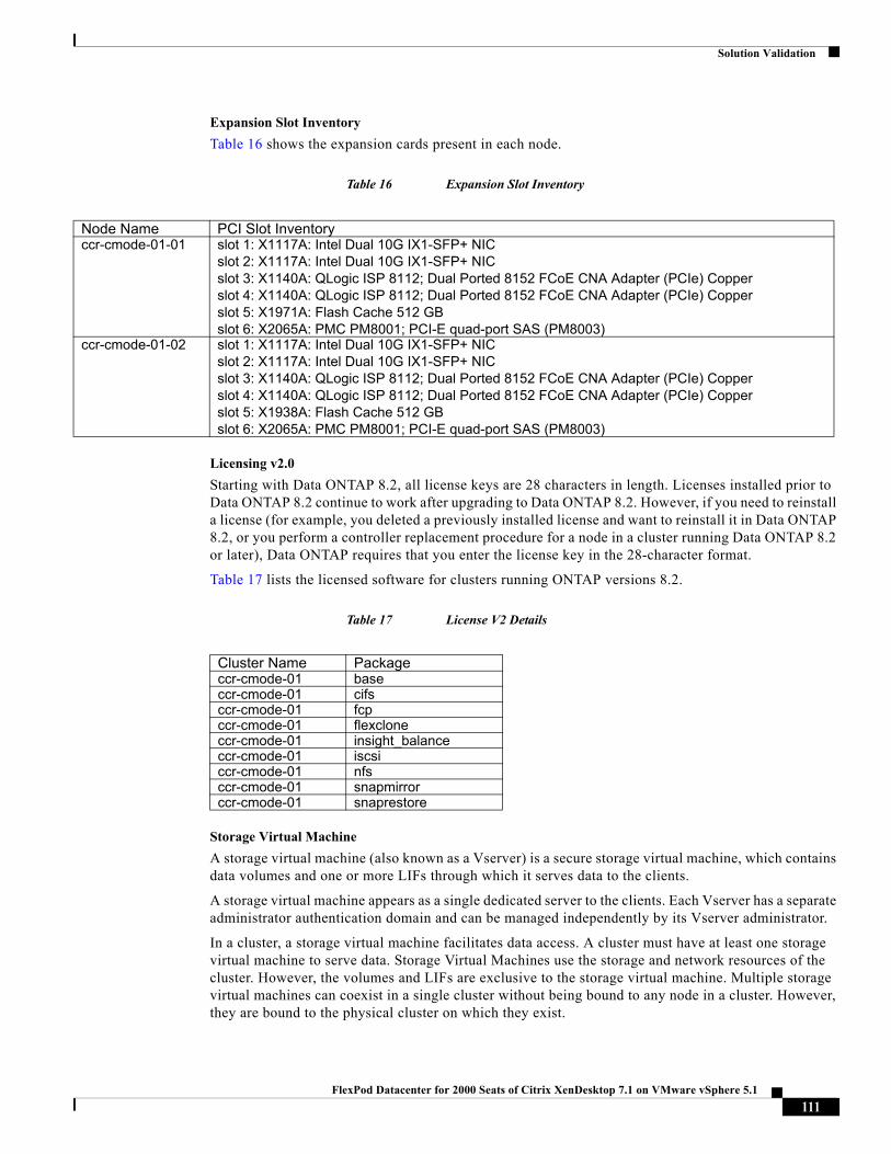
Solution Validation
Expansion Slot Inventory
Table 16 shows the expansion cards present in each node.
Table 16 Expansion Slot Inventory
Licensing v2.0
Starting with Data ONTAP 8.2, all license keys are 28 characters in length. Licenses installed prior to Data ONTAP 8.2 continue to work after upgrading to Data ONTAP 8.2. However, if you need to reinstall a license (for example, you deleted a previously installed license and want to reinstall it in Data ONTAP 8.2, or you perform a controller replacement procedure for a node in a cluster running Data ONTAP 8.2 or later), Data ONTAP requires that you enter the license key in the 28-character format.
Table 17 lists the licensed software for clusters running ONTAP versions 8.2.
Table 17 License V2 Details
Storage Virtual Machine
A storage virtual machine (also known as a Vserver) is a secure storage virtual machine, which contains data volumes and one or more LIFs through which it serves data to the clients.
A storage virtual machine appears as a single dedicated server to the clients. Each Vserver has a separate administrator authentication domain and can be managed independently by its Vserver administrator.
In a cluster, a storage virtual machine facilitates data access. A cluster must have at least one storage virtual machine to serve data. Storage Virtual Machines use the storage and network resources of the cluster. However, the volumes and LIFs are exclusive to the storage virtual machine. Multiple storage virtual machines can coexist in a single cluster without being bound to any node in a cluster. However, they are bound to the physical cluster on which they exist.
Node Name PCI Slot Inventoryccr-cmode-01-01 slot 1: X1117A: Intel Dual 10G IX1-SFP+ NIC
slot 2: X1117A: Intel Dual 10G IX1-SFP+ NICslot 3: X1140A: QLogic ISP 8112; Dual Ported 8152 FCoE CNA Adapter (PCIe) Copperslot 4: X1140A: QLogic ISP 8112; Dual Ported 8152 FCoE CNA Adapter (PCIe) Copperslot 5: X1971A: Flash Cache 512 GBslot 6: X2065A: PMC PM8001; PCI-E quad-port SAS (PM8003)
ccr-cmode-01-02 slot 1: X1117A: Intel Dual 10G IX1-SFP+ NICslot 2: X1117A: Intel Dual 10G IX1-SFP+ NICslot 3: X1140A: QLogic ISP 8112; Dual Ported 8152 FCoE CNA Adapter (PCIe) Copperslot 4: X1140A: QLogic ISP 8112; Dual Ported 8152 FCoE CNA Adapter (PCIe) Copperslot 5: X1938A: Flash Cache 512 GBslot 6: X2065A: PMC PM8001; PCI-E quad-port SAS (PM8003)
Cluster Name Packageccr-cmode-01 baseccr-cmode-01 cifsccr-cmode-01 fcpccr-cmode-01 flexcloneccr-cmode-01 insight_balanceccr-cmode-01 iscsiccr-cmode-01 nfsccr-cmode-01 snapmirrorccr-cmode-01 snaprestore
111FlexPod Datacenter for 2000 Seats of Citrix XenDesktop 7.1 on VMware vSphere 5.1
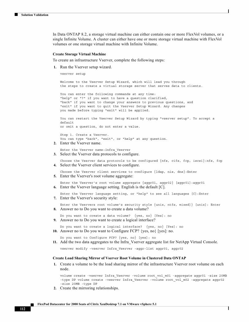
Solution Validation
In Data ONTAP 8.2, a storage virtual machine can either contain one or more FlexVol volumes, or a single Infinite Volume. A cluster can either have one or more storage virtual machine with FlexVol volumes or one storage virtual machine with Infinite Volume.
Create Storage Virtual Machine
To create an infrastructure Vserver, complete the following steps:
1. Run the Vserver setup wizard.
vserver setup
Welcome to the Vserver Setup Wizard, which will lead you throughthe steps to create a virtual storage server that serves data to clients. You can enter the following commands at any time:"help" or "?" if you want to have a question clarified,"back" if you want to change your answers to previous questions, and"exit" if you want to quit the Vserver Setup Wizard. Any changesyou made before typing "exit" will be applied. You can restart the Vserver Setup Wizard by typing "vserver setup". To accept a defaultor omit a question, do not enter a value. Step 1. Create a Vserver.You can type "back", "exit", or "help" at any question.
2. Enter the Vserver name.
Enter the Vserver name:Infra_Vserver
3. Select the Vserver data protocols to configure.
Choose the Vserver data protocols to be configured {nfs, cifs, fcp, iscsi}:nfs, fcp
4. Select the Vserver client services to configure.
Choose the Vserver client services to configure {ldap, nis, dns}:Enter
5. Enter the Vserver's root volume aggregate:
Enter the Vserver's root volume aggregate {aggr01, aggr02} [aggr01]:aggr01
6. Enter the Vserver language setting. English is the default [C].
Enter the Vserver language setting, or "help" to see all languages [C]:Enter
7. Enter the Vserver's security style:
Enter the Vservers root volume's security style {unix, ntfs, mixed]} [unix]: Enter
8. Answer no to Do you want to create a data volume?
Do you want to create a data volume? {yes, no} [Yes]: no
9. Answer no to Do you want to create a logical interface?
Do you want to create a logical interface? {yes, no} [Yes]: no
10. Answer no to Do you want to Configure FCP? {yes, no} [yes]: no.
Do you want to Configure FCP? {yes, no} [yes]: no
11. Add the two data aggregates to the Infra_Vserver aggregate list for NetApp Virtual Console.
vserver modify -vserver Infra_Vserver -aggr-list aggr01, aggr02
Create Load Sharing Mirror of Vserver Root Volume in Clustered Data ONTAP
1. Create a volume to be the load sharing mirror of the infrastructure Vserver root volume on each node.
volume create -vserver Infra_Vserver -volume root_vol_m01 -aggregate aggr01 -size 20MB -type DP volume create -vserver Infra_Vserver -volume root_vol_m02 -aggregate aggr02 -size 20MB -type DP
2. Create the mirroring relationships.
112FlexPod Datacenter for 2000 Seats of Citrix XenDesktop 7.1 on VMware vSphere 5.1
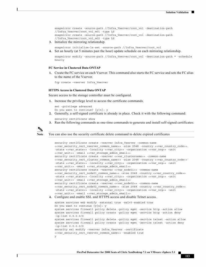
Solution Validation
snapmirror create -source-path //Infra_Vserver/root_vol -destination-path //Infra_Vserver/root_vol_m01 -type LS snapmirror create -source-path //Infra_Vserver/root_vol -destination-path //Infra_Vserver/root_vol_m02 -type LS
3. Initialize the mirroring relationship.
snapmirror initialize-ls-set -source-path //Infra_Vserver/root_vol
4. Set an hourly (at 5 minutes past the hour) update schedule on each mirroring relationship.
snapmirror modify -source-path //Infra_Vserver/root_vol -destination-path * -schedule hourly
FC Service in Clustered Data ONTAP
1. Create the FC service on each Vserver. This command also starts the FC service and sets the FC alias to the name of the Vserver.
fcp create -vserver Infra_Vserver
HTTPS Access in Clustered Data ONTAP
Secure access to the storage controller must be configured.
1. Increase the privilege level to access the certificate commands.
set -privilege advancedDo you want to continue? {y|n}: y
2. Generally, a self-signed certificate is already in place. Check it with the following command:
security certificate show
3. Run the following commands as one-time commands to generate and install self-signed certificates:
Note You can also use the security certificate delete command to delete expired certificates
security certificate create -vserver Infra_Vserver -common-name <<var_security_cert_vserver_common_name>> -size 2048 -country <<var_country_code>> -state <<var_state>> -locality <<var_city>> -organization <<var_org>> -unit <<var_unit>> -email <<var_storage_admin_email>>security certificate create -vserver <<var_clustername>> -common-name <<var_security_cert_cluster_common_name>> -size 2048 -country <<var_country_code>> -state <<var_state>> -locality <<var_city>> -organization <<var_org>> -unit <<var_unit>> -email <<var_storage_admin_email>>security certificate create -vserver <<var_node01>> -common-name <<var_security_cert_node01_common_name>> -size 2048 -country <<var_country_code>> -state <<var_state>> -locality <<var_city>> -organization <<var_org>> -unit <<var_unit>> -email <<var_storage_admin_email>>security certificate create -vserver <<var_node02>> -common-name <<var_security_cert_node02_common_name>> -size 2048 -country <<var_country_code>> -state <<var_state>> -locality <<var_city>> -organization <<var_org>> -unit <<var_unit>> -email <<var_storage_admin_email>>
4. Configure and enable SSL and HTTPS access and disable Telnet access.
system services web modify -external true -sslv3-enabled trueDo you want to continue {y|n}: ysystem services firewall policy delete -policy mgmt -service http -action allowsystem services firewall policy create -policy mgmt -service http -action deny -ip-list 0.0.0.0/0system services firewall policy delete -policy mgmt -service telnet -action allowsystem services firewall policy create -policy mgmt -service telnet -action deny -ip-list 0.0.0.0/0security ssl modify -vserver Infra_Vserver -certificate <<var_security_cert_vserver_common_name>> -enabled truey
113FlexPod Datacenter for 2000 Seats of Citrix XenDesktop 7.1 on VMware vSphere 5.1
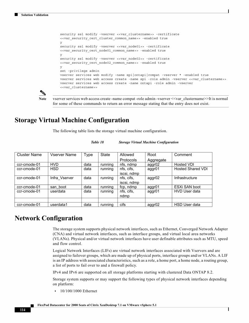
Solution Validation
security ssl modify -vserver <<var_clustername>> -certificate <<var_security_cert_cluster_common_name>> -enabled trueysecurity ssl modify -vserver <<var_node01>> -certificate <<var_security_cert_node01_common_name>> -enabled trueysecurity ssl modify -vserver <<var_node02>> -certificate <<var_security_cert_node02_common_name>> -enabled trueyset -privilege adminvserver services web modify -name spi|ontapi|compat -vserver * -enabled truevserver services web access create -name spi -role admin -vserver <<var_clustername>>vserver services web access create -name ontapi -role admin -vserver <<var_clustername>>
Note vserver services web access create -name compat -role admin -vserver <<var_clustername>>It is normal for some of these commands to return an error message stating that the entry does not exist.
Storage Virtual Machine Configuration
The following table lists the storage virtual machine configuration.
Table 18 Storage Virtual Machine Configuration
Network Configuration
The storage system supports physical network interfaces, such as Ethernet, Converged Network Adapter (CNA) and virtual network interfaces, such as interface groups, and virtual local area networks (VLANs). Physical and/or virtual network interfaces have user definable attributes such as MTU, speed and flow control.
Logical Network Interfaces (LIFs) are virtual network interfaces associated with Vservers and are assigned to failover groups, which are made up of physical ports, interface groups and/or VLANs. A LIF is an IP address with associated characteristics, such as a role, a home port, a home node, a routing group, a list of ports to fail over to and a firewall policy.
IPv4 and IPv6 are supported on all storage platforms starting with clustered Data ONTAP 8.2.
Storage system supports or may support the following types of physical network interfaces depending on platform:
• 10/100/1000 Ethernet
Cluster Name Vserver Name Type State Allowed Protocols
Root Aggregate
Comment
ccr-cmode-01 HVD data running nfs, ndmp aggr02 Hosted VDIccr-cmode-01 HSD data running nfs, cifs,
iscsi, ndmpaggr01 Hosted Shared VDI
ccr-cmode-01 Infra_Vserver data running nfs, cifs, iscsi, ndmp
aggr02 Infrastructure
ccr-cmode-01 san_boot data running fcp, ndmp aggr01 ESXi SAN bootccr-cmode-01 userdata data running nfs, cifs,
ndmpaggr01 HVD User data
ccr-cmode-01 userdata1 data running cifs aggr02 HSD User data
114FlexPod Datacenter for 2000 Seats of Citrix XenDesktop 7.1 on VMware vSphere 5.1
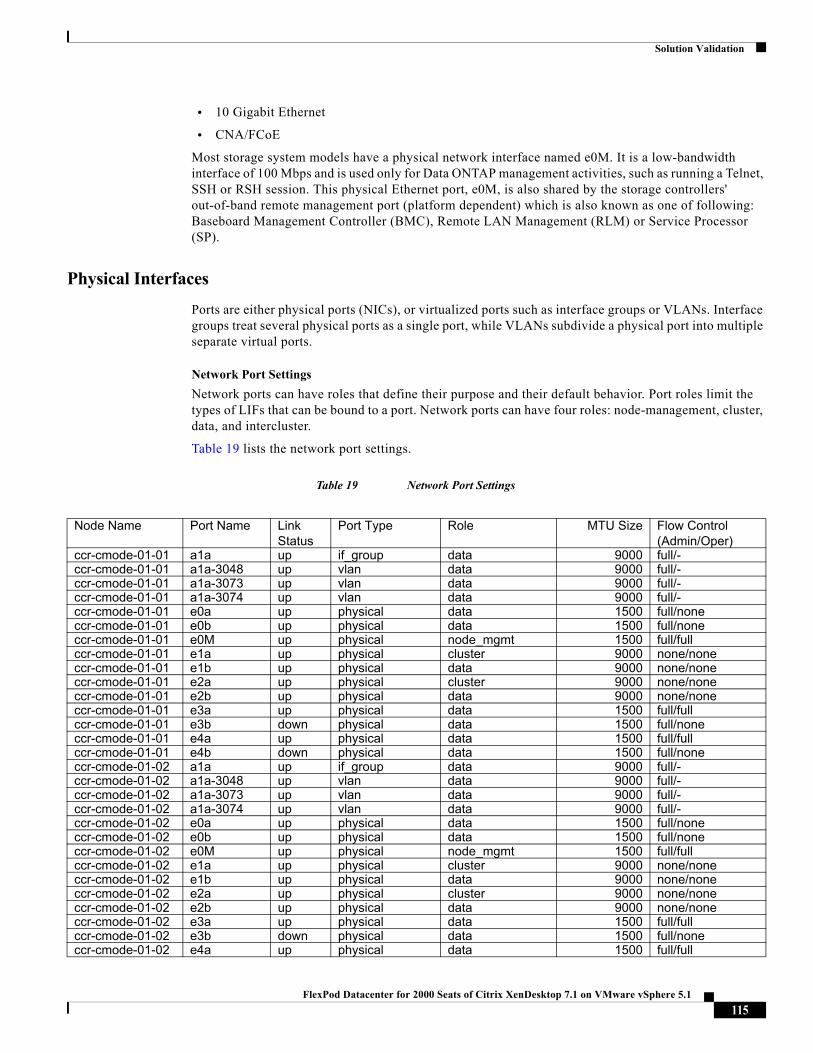
Solution Validation
• 10 Gigabit Ethernet
• CNA/FCoE
Most storage system models have a physical network interface named e0M. It is a low-bandwidth interface of 100 Mbps and is used only for Data ONTAP management activities, such as running a Telnet, SSH or RSH session. This physical Ethernet port, e0M, is also shared by the storage controllers' out-of-band remote management port (platform dependent) which is also known as one of following: Baseboard Management Controller (BMC), Remote LAN Management (RLM) or Service Processor (SP).
Physical Interfaces
Ports are either physical ports (NICs), or virtualized ports such as interface groups or VLANs. Interface groups treat several physical ports as a single port, while VLANs subdivide a physical port into multiple separate virtual ports.
Network Port Settings
Network ports can have roles that define their purpose and their default behavior. Port roles limit the types of LIFs that can be bound to a port. Network ports can have four roles: node-management, cluster, data, and intercluster.
Table 19 lists the network port settings.
Table 19 Network Port Settings
Node Name Port Name Link Status
Port Type Role MTU Size Flow Control (Admin/Oper)
ccr-cmode-01-01 a1a up if_group data 9000 full/-ccr-cmode-01-01 a1a-3048 up vlan data 9000 full/-ccr-cmode-01-01 a1a-3073 up vlan data 9000 full/-ccr-cmode-01-01 a1a-3074 up vlan data 9000 full/-ccr-cmode-01-01 e0a up physical data 1500 full/noneccr-cmode-01-01 e0b up physical data 1500 full/noneccr-cmode-01-01 e0M up physical node_mgmt 1500 full/fullccr-cmode-01-01 e1a up physical cluster 9000 none/noneccr-cmode-01-01 e1b up physical data 9000 none/noneccr-cmode-01-01 e2a up physical cluster 9000 none/noneccr-cmode-01-01 e2b up physical data 9000 none/noneccr-cmode-01-01 e3a up physical data 1500 full/fullccr-cmode-01-01 e3b down physical data 1500 full/noneccr-cmode-01-01 e4a up physical data 1500 full/fullccr-cmode-01-01 e4b down physical data 1500 full/noneccr-cmode-01-02 a1a up if_group data 9000 full/-ccr-cmode-01-02 a1a-3048 up vlan data 9000 full/-ccr-cmode-01-02 a1a-3073 up vlan data 9000 full/-ccr-cmode-01-02 a1a-3074 up vlan data 9000 full/-ccr-cmode-01-02 e0a up physical data 1500 full/noneccr-cmode-01-02 e0b up physical data 1500 full/noneccr-cmode-01-02 e0M up physical node_mgmt 1500 full/fullccr-cmode-01-02 e1a up physical cluster 9000 none/noneccr-cmode-01-02 e1b up physical data 9000 none/noneccr-cmode-01-02 e2a up physical cluster 9000 none/noneccr-cmode-01-02 e2b up physical data 9000 none/noneccr-cmode-01-02 e3a up physical data 1500 full/fullccr-cmode-01-02 e3b down physical data 1500 full/noneccr-cmode-01-02 e4a up physical data 1500 full/full
115FlexPod Datacenter for 2000 Seats of Citrix XenDesktop 7.1 on VMware vSphere 5.1
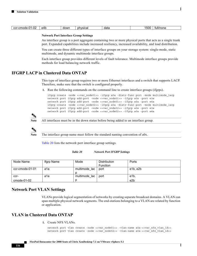
Solution Validation
Network Port Interface Group Settings
An interface group is a port aggregate containing two or more physical ports that acts as a single trunk port. Expanded capabilities include increased resiliency, increased availability, and load distribution.
You can create three different types of interface groups on your storage system: single-mode, static multimode, and dynamic multimode interface groups.
Each interface group provides different levels of fault tolerance. Multimode interface groups provide methods for load balancing network traffic.
IFGRP LACP in Clustered Data ONTAP
This type of interface group requires two or more Ethernet interfaces and a switch that supports LACP. Therefore, make sure that the switch is configured properly.
1. Run the following commands on the command line to create interface groups (ifgrps).
ifgrp create -node <<var_node01>> -ifgrp a0a -distr-func port -mode multimode_lacpnetwork port ifgrp add-port -node <<var_node01>> -ifgrp a0a -port e3anetwork port ifgrp add-port -node <<var_node01>> -ifgrp a0a -port e4aifgrp create -node <<var_node02>> -ifgrp a0a -distr-func port -mode multimode_lacpnetwork port ifgrp add-port -node <<var_node02>> -ifgrp a0a -port e3anetwork port ifgrp add-port -node <<var_node02>> -ifgrp a0a -port e4a
Note All interfaces must be in the down status before being added to an interface group.
Note The interface group name must follow the standard naming convention of a0x.
Table 20 lists the network port interface group settings.
Table 20 Network Port IFGRP Settings
Network Port VLAN Settings
VLANs provide logical segmentation of networks by creating separate broadcast domains. A VLAN can span multiple physical network segments. The end-stations belonging to a VLAN are related by function or application.
VLAN in Clustered Data ONTAP
1. Create NFS VLANs.
network port vlan create -node <<var_node01>> -vlan-name a0a-<<var_nfs_vlan_id>>network port vlan create -node <<var_node02>> -vlan-name a0a-<<var_nfs_vlan_id>>
ccr-cmode-01-02 e4b down physical data 1500 full/none
Node Name Ifgrp Name Mode Distribution Function
Ports
ccr-cmode-01-01 a1a multimode_lacp
port e1b, e2b
ccr-
cmode-01-02
a1a multimode_lacp
port e1b,
e2b
116FlexPod Datacenter for 2000 Seats of Citrix XenDesktop 7.1 on VMware vSphere 5.1
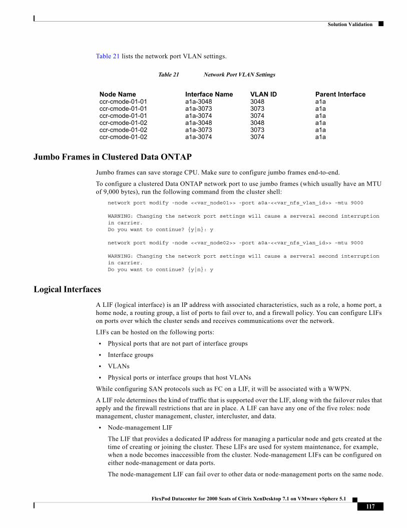
Solution Validation
Table 21 lists the network port VLAN settings.
Table 21 Network Port VLAN Settings
Jumbo Frames in Clustered Data ONTAP
Jumbo frames can save storage CPU. Make sure to configure jumbo frames end-to-end.
To configure a clustered Data ONTAP network port to use jumbo frames (which usually have an MTU of 9,000 bytes), run the following command from the cluster shell:
network port modify -node <<var_node01>> -port a0a-<<var_nfs_vlan_id>> -mtu 9000
WARNING: Changing the network port settings will cause a serveral second interruption in carrier.Do you want to continue? {y|n}: y
network port modify -node <<var_node02>> -port a0a-<<var_nfs_vlan_id>> -mtu 9000
WARNING: Changing the network port settings will cause a serveral second interruption in carrier.Do you want to continue? {y|n}: y
Logical Interfaces
A LIF (logical interface) is an IP address with associated characteristics, such as a role, a home port, a home node, a routing group, a list of ports to fail over to, and a firewall policy. You can configure LIFs on ports over which the cluster sends and receives communications over the network.
LIFs can be hosted on the following ports:
• Physical ports that are not part of interface groups
• Interface groups
• VLANs
• Physical ports or interface groups that host VLANs
While configuring SAN protocols such as FC on a LIF, it will be associated with a WWPN.
A LIF role determines the kind of traffic that is supported over the LIF, along with the failover rules that apply and the firewall restrictions that are in place. A LIF can have any one of the five roles: node management, cluster management, cluster, intercluster, and data.
• Node-management LIF
The LIF that provides a dedicated IP address for managing a particular node and gets created at the time of creating or joining the cluster. These LIFs are used for system maintenance, for example, when a node becomes inaccessible from the cluster. Node-management LIFs can be configured on either node-management or data ports.
The node-management LIF can fail over to other data or node-management ports on the same node.
Node Name Interface Name VLAN ID Parent Interfaceccr-cmode-01-01 a1a-3048 3048 a1accr-cmode-01-01 a1a-3073 3073 a1accr-cmode-01-01 a1a-3074 3074 a1accr-cmode-01-02 a1a-3048 3048 a1accr-cmode-01-02 a1a-3073 3073 a1accr-cmode-01-02 a1a-3074 3074 a1a
117FlexPod Datacenter for 2000 Seats of Citrix XenDesktop 7.1 on VMware vSphere 5.1
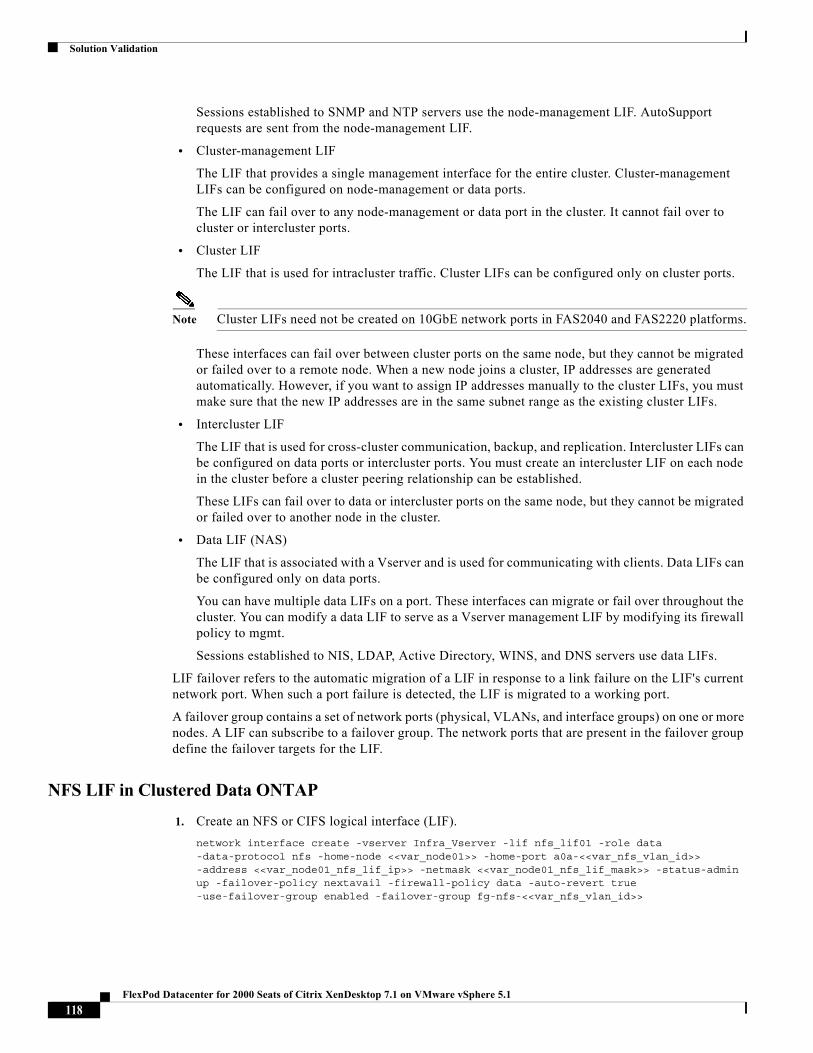
Solution Validation
Sessions established to SNMP and NTP servers use the node-management LIF. AutoSupport requests are sent from the node-management LIF.
• Cluster-management LIF
The LIF that provides a single management interface for the entire cluster. Cluster-management LIFs can be configured on node-management or data ports.
The LIF can fail over to any node-management or data port in the cluster. It cannot fail over to cluster or intercluster ports.
• Cluster LIF
The LIF that is used for intracluster traffic. Cluster LIFs can be configured only on cluster ports.
Note Cluster LIFs need not be created on 10GbE network ports in FAS2040 and FAS2220 platforms.
These interfaces can fail over between cluster ports on the same node, but they cannot be migrated or failed over to a remote node. When a new node joins a cluster, IP addresses are generated automatically. However, if you want to assign IP addresses manually to the cluster LIFs, you must make sure that the new IP addresses are in the same subnet range as the existing cluster LIFs.
• Intercluster LIF
The LIF that is used for cross-cluster communication, backup, and replication. Intercluster LIFs can be configured on data ports or intercluster ports. You must create an intercluster LIF on each node in the cluster before a cluster peering relationship can be established.
These LIFs can fail over to data or intercluster ports on the same node, but they cannot be migrated or failed over to another node in the cluster.
• Data LIF (NAS)
The LIF that is associated with a Vserver and is used for communicating with clients. Data LIFs can be configured only on data ports.
You can have multiple data LIFs on a port. These interfaces can migrate or fail over throughout the cluster. You can modify a data LIF to serve as a Vserver management LIF by modifying its firewall policy to mgmt.
Sessions established to NIS, LDAP, Active Directory, WINS, and DNS servers use data LIFs.
LIF failover refers to the automatic migration of a LIF in response to a link failure on the LIF's current network port. When such a port failure is detected, the LIF is migrated to a working port.
A failover group contains a set of network ports (physical, VLANs, and interface groups) on one or more nodes. A LIF can subscribe to a failover group. The network ports that are present in the failover group define the failover targets for the LIF.
NFS LIF in Clustered Data ONTAP
1. Create an NFS or CIFS logical interface (LIF).
network interface create -vserver Infra_Vserver -lif nfs_lif01 -role data -data-protocol nfs -home-node <<var_node01>> -home-port a0a-<<var_nfs_vlan_id>> -address <<var_node01_nfs_lif_ip>> -netmask <<var_node01_nfs_lif_mask>> -status-admin up -failover-policy nextavail -firewall-policy data -auto-revert true -use-failover-group enabled -failover-group fg-nfs-<<var_nfs_vlan_id>>
118FlexPod Datacenter for 2000 Seats of Citrix XenDesktop 7.1 on VMware vSphere 5.1
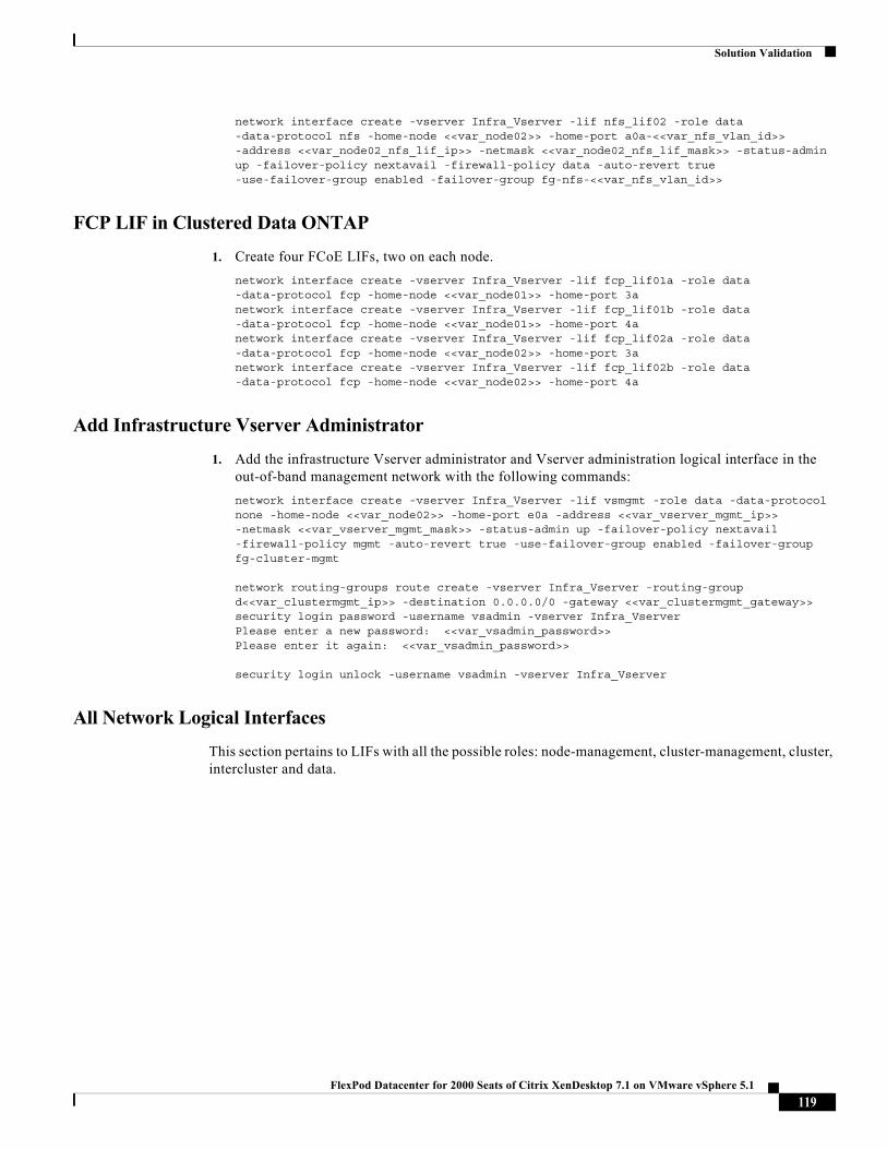
Solution Validation
network interface create -vserver Infra_Vserver -lif nfs_lif02 -role data -data-protocol nfs -home-node <<var_node02>> -home-port a0a-<<var_nfs_vlan_id>> -address <<var_node02_nfs_lif_ip>> -netmask <<var_node02_nfs_lif_mask>> -status-admin up -failover-policy nextavail -firewall-policy data -auto-revert true -use-failover-group enabled -failover-group fg-nfs-<<var_nfs_vlan_id>>
FCP LIF in Clustered Data ONTAP
1. Create four FCoE LIFs, two on each node.
network interface create -vserver Infra_Vserver -lif fcp_lif01a -role data -data-protocol fcp -home-node <<var_node01>> -home-port 3anetwork interface create -vserver Infra_Vserver -lif fcp_lif01b -role data -data-protocol fcp -home-node <<var_node01>> -home-port 4anetwork interface create -vserver Infra_Vserver -lif fcp_lif02a -role data -data-protocol fcp -home-node <<var_node02>> -home-port 3anetwork interface create -vserver Infra_Vserver -lif fcp_lif02b -role data -data-protocol fcp -home-node <<var_node02>> -home-port 4a
Add Infrastructure Vserver Administrator
1. Add the infrastructure Vserver administrator and Vserver administration logical interface in the out-of-band management network with the following commands:
network interface create -vserver Infra_Vserver -lif vsmgmt -role data -data-protocol none -home-node <<var_node02>> -home-port e0a -address <<var_vserver_mgmt_ip>> -netmask <<var_vserver_mgmt_mask>> -status-admin up -failover-policy nextavail -firewall-policy mgmt -auto-revert true -use-failover-group enabled -failover-group fg-cluster-mgmt
network routing-groups route create -vserver Infra_Vserver -routing-group d<<var_clustermgmt_ip>> -destination 0.0.0.0/0 -gateway <<var_clustermgmt_gateway>>security login password -username vsadmin -vserver Infra_VserverPlease enter a new password: <<var_vsadmin_password>>Please enter it again: <<var_vsadmin_password>>
security login unlock -username vsadmin -vserver Infra_Vserver
All Network Logical Interfaces
This section pertains to LIFs with all the possible roles: node-management, cluster-management, cluster, intercluster and data.
119FlexPod Datacenter for 2000 Seats of Citrix XenDesktop 7.1 on VMware vSphere 5.1
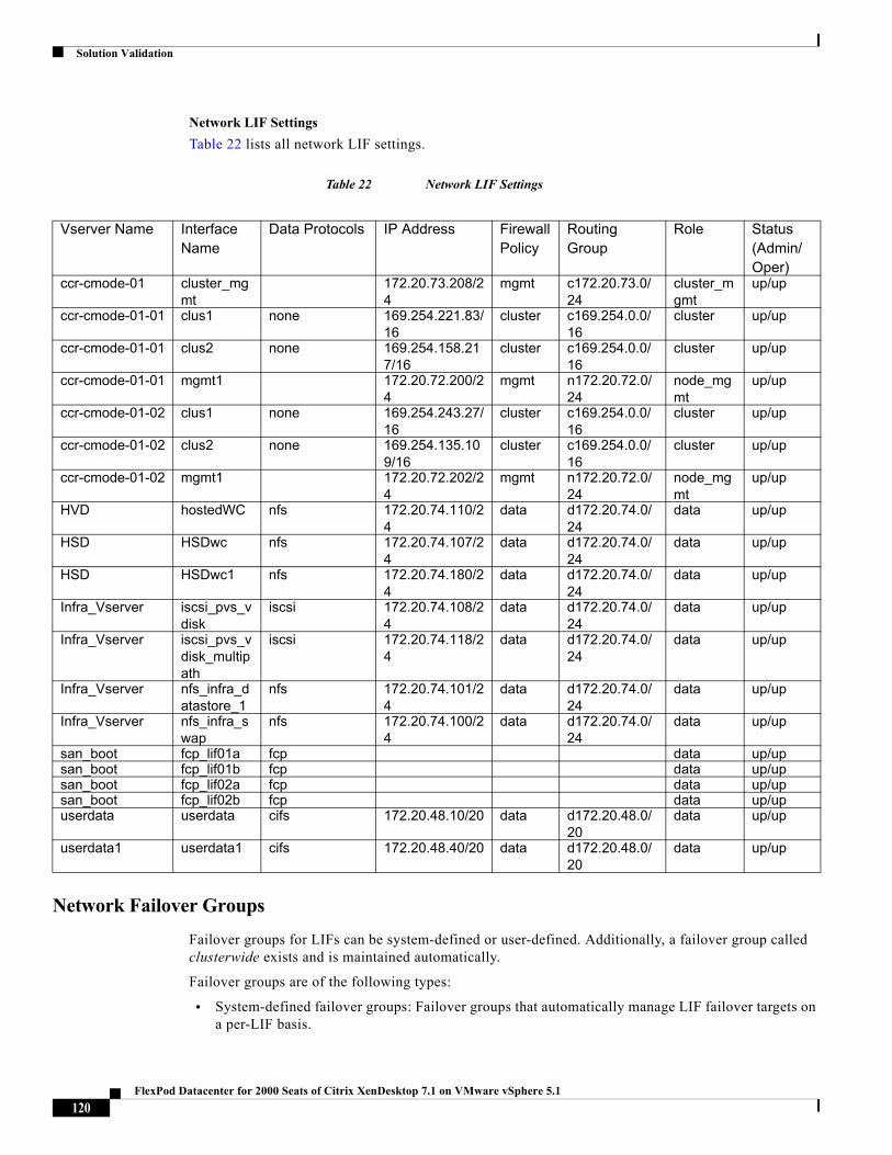
Solution Validation
Network LIF Settings
Table 22 lists all network LIF settings.
Table 22 Network LIF Settings
Network Failover Groups
Failover groups for LIFs can be system-defined or user-defined. Additionally, a failover group called clusterwide exists and is maintained automatically.
Failover groups are of the following types:
• System-defined failover groups: Failover groups that automatically manage LIF failover targets on a per-LIF basis.
Vserver Name Interface Name
Data Protocols IP Address Firewall Policy
Routing Group
Role Status(Admin/Oper)
ccr-cmode-01 cluster_mgmt
172.20.73.208/24
mgmt c172.20.73.0/24
cluster_mgmt
up/up
ccr-cmode-01-01 clus1 none 169.254.221.83/16
cluster c169.254.0.0/16
cluster up/up
ccr-cmode-01-01 clus2 none 169.254.158.217/16
cluster c169.254.0.0/16
cluster up/up
ccr-cmode-01-01 mgmt1 172.20.72.200/24
mgmt n172.20.72.0/24
node_mgmt
up/up
ccr-cmode-01-02 clus1 none 169.254.243.27/16
cluster c169.254.0.0/16
cluster up/up
ccr-cmode-01-02 clus2 none 169.254.135.109/16
cluster c169.254.0.0/16
cluster up/up
ccr-cmode-01-02 mgmt1 172.20.72.202/24
mgmt n172.20.72.0/24
node_mgmt
up/up
HVD hostedWC nfs 172.20.74.110/24
data d172.20.74.0/24
data up/up
HSD HSDwc nfs 172.20.74.107/24
data d172.20.74.0/24
data up/up
HSD HSDwc1 nfs 172.20.74.180/24
data d172.20.74.0/24
data up/up
Infra_Vserver iscsi_pvs_vdisk
iscsi 172.20.74.108/24
data d172.20.74.0/24
data up/up
Infra_Vserver iscsi_pvs_vdisk_multipath
iscsi 172.20.74.118/24
data d172.20.74.0/24
data up/up
Infra_Vserver nfs_infra_datastore_1
nfs 172.20.74.101/24
data d172.20.74.0/24
data up/up
Infra_Vserver nfs_infra_swap
nfs 172.20.74.100/24
data d172.20.74.0/24
data up/up
san_boot fcp_lif01a fcp data up/upsan_boot fcp_lif01b fcp data up/upsan_boot fcp_lif02a fcp data up/upsan_boot fcp_lif02b fcp data up/upuserdata userdata cifs 172.20.48.10/20 data d172.20.48.0/
20data up/up
userdata1 userdata1 cifs 172.20.48.40/20 data d172.20.48.0/20
data up/up
120FlexPod Datacenter for 2000 Seats of Citrix XenDesktop 7.1 on VMware vSphere 5.1
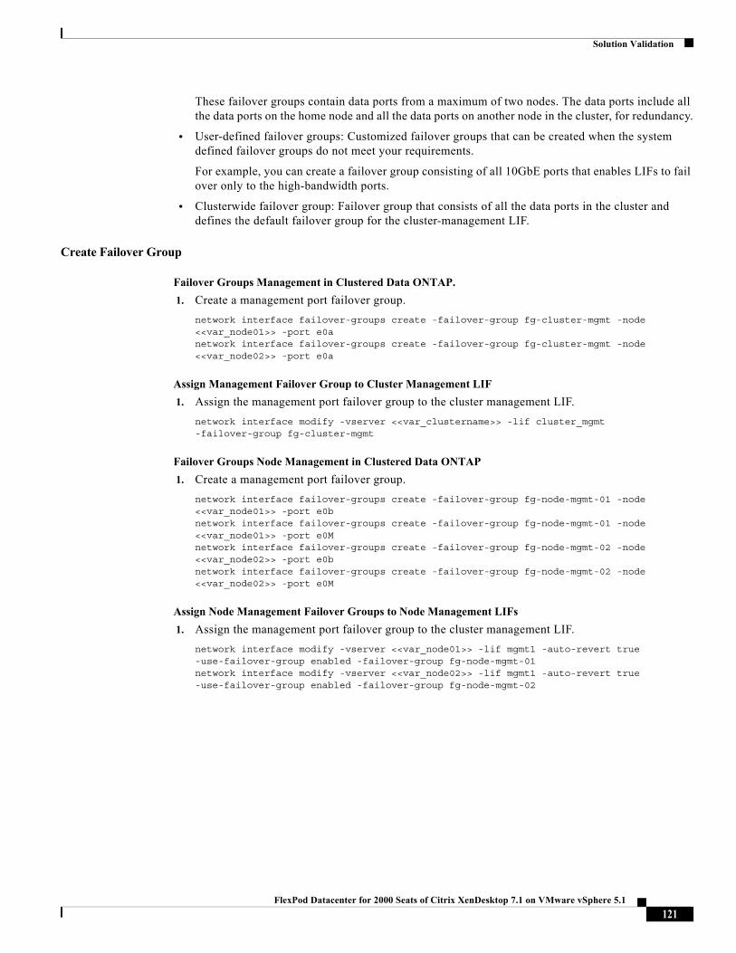
Solution Validation
These failover groups contain data ports from a maximum of two nodes. The data ports include all the data ports on the home node and all the data ports on another node in the cluster, for redundancy.
• User-defined failover groups: Customized failover groups that can be created when the system defined failover groups do not meet your requirements.
For example, you can create a failover group consisting of all 10GbE ports that enables LIFs to fail over only to the high-bandwidth ports.
• Clusterwide failover group: Failover group that consists of all the data ports in the cluster and defines the default failover group for the cluster-management LIF.
Create Failover Group
Failover Groups Management in Clustered Data ONTAP.
1. Create a management port failover group.
network interface failover-groups create -failover-group fg-cluster-mgmt -node <<var_node01>> -port e0anetwork interface failover-groups create -failover-group fg-cluster-mgmt -node <<var_node02>> -port e0a
Assign Management Failover Group to Cluster Management LIF
1. Assign the management port failover group to the cluster management LIF.
network interface modify -vserver <<var_clustername>> -lif cluster_mgmt -failover-group fg-cluster-mgmt
Failover Groups Node Management in Clustered Data ONTAP
1. Create a management port failover group.
network interface failover-groups create -failover-group fg-node-mgmt-01 -node <<var_node01>> -port e0bnetwork interface failover-groups create -failover-group fg-node-mgmt-01 -node <<var_node01>> -port e0Mnetwork interface failover-groups create -failover-group fg-node-mgmt-02 -node <<var_node02>> -port e0bnetwork interface failover-groups create -failover-group fg-node-mgmt-02 -node <<var_node02>> -port e0M
Assign Node Management Failover Groups to Node Management LIFs
1. Assign the management port failover group to the cluster management LIF.
network interface modify -vserver <<var_node01>> -lif mgmt1 -auto-revert true -use-failover-group enabled -failover-group fg-node-mgmt-01network interface modify -vserver <<var_node02>> -lif mgmt1 -auto-revert true -use-failover-group enabled -failover-group fg-node-mgmt-02
121FlexPod Datacenter for 2000 Seats of Citrix XenDesktop 7.1 on VMware vSphere 5.1
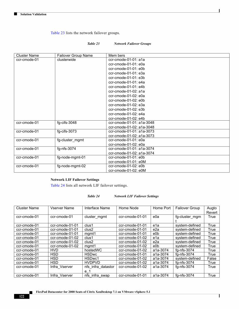
Solution Validation
Table 23 lists the network failover groups.
Table 23 Network Failover Groups
Network LIF Failover Settings
Table 24 lists all network LIF failover settings.
Table 24 Network LIF Failover Settings
Cluster Name Failover Group Name Mem bersccr-cmode-01 clusterwide ccr-cmode-01-01: a1a
ccr-cmode-01-01: e0accr-cmode-01-01: e0bccr-cmode-01-01: e3accr-cmode-01-01: e3bccr-cmode-01-01: e4accr-cmode-01-01: e4bccr-cmode-01-02: a1accr-cmode-01-02: e0accr-cmode-01-02: e0bccr-cmode-01-02: e3accr-cmode-01-02: e3bccr-cmode-01-02: e4accr-cmode-01-02: e4b
ccr-cmode-01 fg-cifs-3048 ccr-cmode-01-01: a1a-3048ccr-cmode-01-02: a1a-3048
ccr-cmode-01 fg-cifs-3073 ccr-cmode-01-01: a1a-3073ccr-cmode-01-02: a1a-3073
ccr-cmode-01 fg-cluster_mgmt ccr-cmode-01-01: e0accr-cmode-01-02: e0a
ccr-cmode-01 fg-nfs-3074 ccr-cmode-01-01: a1a-3074ccr-cmode-01-02: a1a-3074
ccr-cmode-01 fg-node-mgmt-01 ccr-cmode-01-01: e0bccr-cmode-01-01: e0M
ccr-cmode-01 fg-node-mgmt-02 ccr-cmode-01-02: e0bccr-cmode-01-02: e0M
Cluster Name Vserver Name Interface Name Home Node Home Port Failover Group Augto Revert
ccr-cmode-01 ccr-cmode-01 cluster_mgmt ccr-cmode-01-01 e0a fg-cluster_mgmt
True
ccr-cmode-01 ccr-cmode-01-01 clus1 ccr-cmode-01-01 e1a system-defined Trueccr-cmode-01 ccr-cmode-01-01 clus2 ccr-cmode-01-01 e2a system-defined Trueccr-cmode-01 ccr-cmode-01-01 mgmt1 ccr-cmode-01-01 e0b system-defined Trueccr-cmode-01 ccr-cmode-01-02 clus1 ccr-cmode-01-02 e1a system-defined Trueccr-cmode-01 ccr-cmode-01-02 clus2 ccr-cmode-01-02 e2a system-defined Trueccr-cmode-01 ccr-cmode-01-02 mgmt1 ccr-cmode-01-02 e0b system-defined Trueccr-cmode-01 HVD hostedWC ccr-cmode-01-02 a1a-3074 fg-nfs-3074 Trueccr-cmode-01 HSD HSDwc ccr-cmode-01-01 a1a-3074 fg-nfs-3074 Trueccr-cmode-01 HSD HSDwc1 ccr-cmode-01-02 a1a-3074 system-defined Falseccr-cmode-01 HSD HVDPVD ccr-cmode-01-02 a1a-3074 fg-nfs-3074 Trueccr-cmode-01 Infra_Vserver nfs_infra_datastor
e_1ccr-cmode-01-02 a1a-3074 fg-nfs-3074 True
ccr-cmode-01 Infra_Vserver nfs_infra_swap ccr-cmode-01-01 a1a-3074 fg-nfs-3074 True
122FlexPod Datacenter for 2000 Seats of Citrix XenDesktop 7.1 on VMware vSphere 5.1
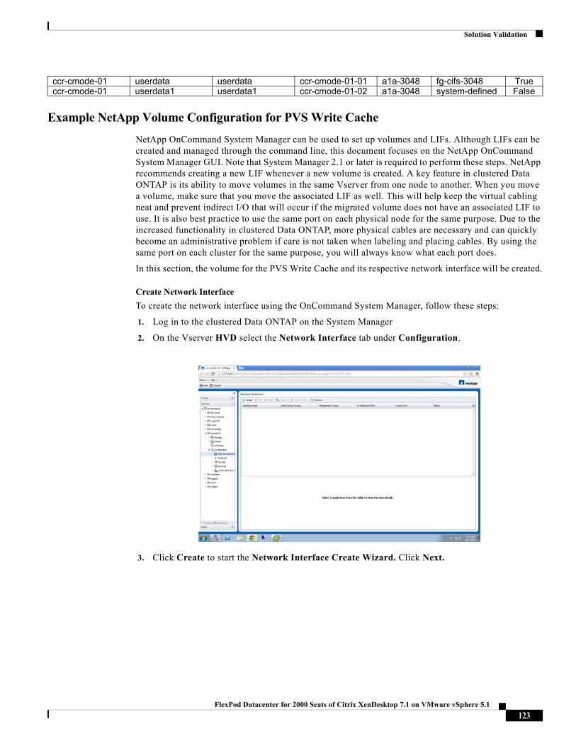
Solution Validation
Example NetApp Volume Configuration for PVS Write Cache
NetApp OnCommand System Manager can be used to set up volumes and LIFs. Although LIFs can be created and managed through the command line, this document focuses on the NetApp OnCommand System Manager GUI. Note that System Manager 2.1 or later is required to perform these steps. NetApp recommends creating a new LIF whenever a new volume is created. A key feature in clustered Data ONTAP is its ability to move volumes in the same Vserver from one node to another. When you move a volume, make sure that you move the associated LIF as well. This will help keep the virtual cabling neat and prevent indirect I/O that will occur if the migrated volume does not have an associated LIF to use. It is also best practice to use the same port on each physical node for the same purpose. Due to the increased functionality in clustered Data ONTAP, more physical cables are necessary and can quickly become an administrative problem if care is not taken when labeling and placing cables. By using the same port on each cluster for the same purpose, you will always know what each port does.
In this section, the volume for the PVS Write Cache and its respective network interface will be created.
Create Network Interface
To create the network interface using the OnCommand System Manager, follow these steps:
1. Log in to the clustered Data ONTAP on the System Manager
2. On the Vserver HVD select the Network Interface tab under Configuration.
3. Click Create to start the Network Interface Create Wizard. Click Next.
ccr-cmode-01 userdata userdata ccr-cmode-01-01 a1a-3048 fg-cifs-3048 Trueccr-cmode-01 userdata1 userdata1 ccr-cmode-01-02 a1a-3048 system-defined False
123FlexPod Datacenter for 2000 Seats of Citrix XenDesktop 7.1 on VMware vSphere 5.1
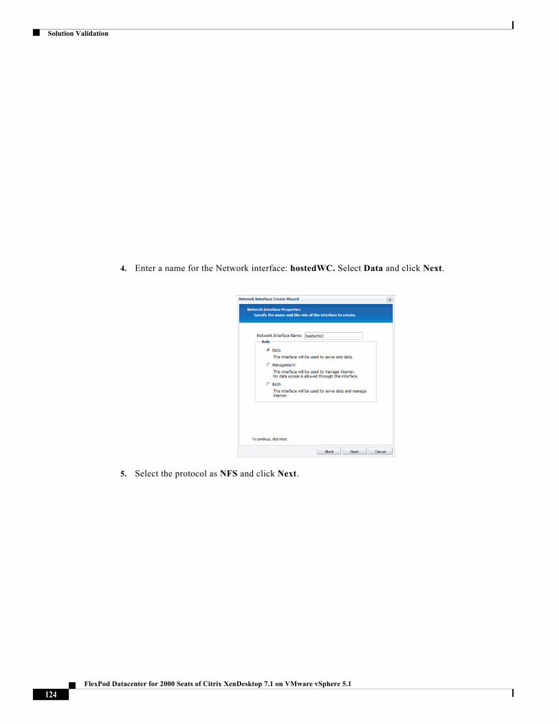
Solution Validation
4. Enter a name for the Network interface: hostedWC. Select Data and click Next.
5. Select the protocol as NFS and click Next.
124FlexPod Datacenter for 2000 Seats of Citrix XenDesktop 7.1 on VMware vSphere 5.1
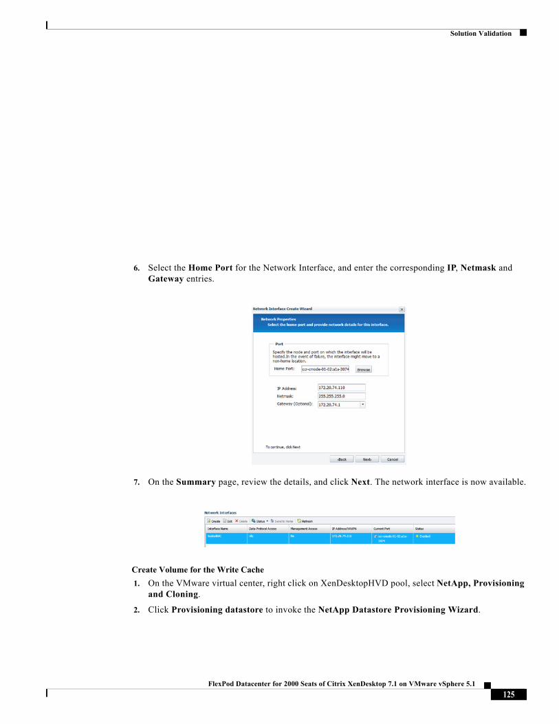
Solution Validation
6. Select the Home Port for the Network Interface, and enter the corresponding IP, Netmask and Gateway entries.
7. On the Summary page, review the details, and click Next. The network interface is now available.
Create Volume for the Write Cache
1. On the VMware virtual center, right click on XenDesktopHVD pool, select NetApp, Provisioning and Cloning.
2. Click Provisioning datastore to invoke the NetApp Datastore Provisioning Wizard.
125FlexPod Datacenter for 2000 Seats of Citrix XenDesktop 7.1 on VMware vSphere 5.1
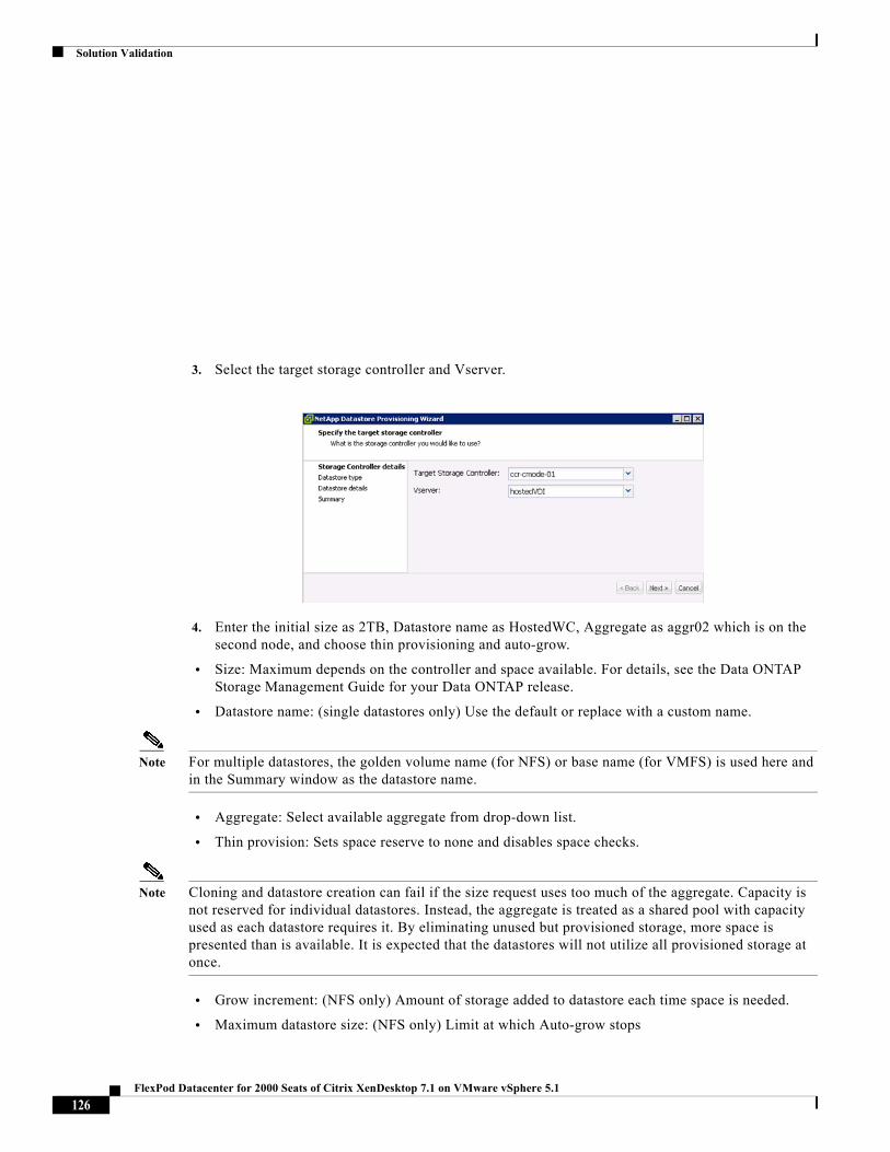
Solution Validation
3. Select the target storage controller and Vserver.
4. Enter the initial size as 2TB, Datastore name as HostedWC, Aggregate as aggr02 which is on the second node, and choose thin provisioning and auto-grow.
• Size: Maximum depends on the controller and space available. For details, see the Data ONTAP Storage Management Guide for your Data ONTAP release.
• Datastore name: (single datastores only) Use the default or replace with a custom name.
Note For multiple datastores, the golden volume name (for NFS) or base name (for VMFS) is used here and in the Summary window as the datastore name.
• Aggregate: Select available aggregate from drop-down list.
• Thin provision: Sets space reserve to none and disables space checks.
Note Cloning and datastore creation can fail if the size request uses too much of the aggregate. Capacity is not reserved for individual datastores. Instead, the aggregate is treated as a shared pool with capacity used as each datastore requires it. By eliminating unused but provisioned storage, more space is presented than is available. It is expected that the datastores will not utilize all provisioned storage at once.
• Grow increment: (NFS only) Amount of storage added to datastore each time space is needed.
• Maximum datastore size: (NFS only) Limit at which Auto-grow stops
126FlexPod Datacenter for 2000 Seats of Citrix XenDesktop 7.1 on VMware vSphere 5.1
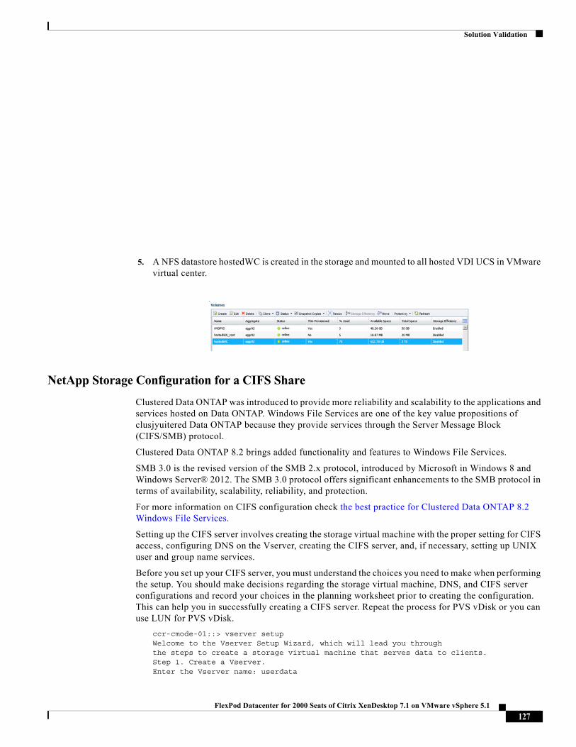
Solution Validation
5. A NFS datastore hostedWC is created in the storage and mounted to all hosted VDI UCS in VMware virtual center.
NetApp Storage Configuration for a CIFS Share
Clustered Data ONTAP was introduced to provide more reliability and scalability to the applications and services hosted on Data ONTAP. Windows File Services are one of the key value propositions of clusjyuitered Data ONTAP because they provide services through the Server Message Block (CIFS/SMB) protocol.
Clustered Data ONTAP 8.2 brings added functionality and features to Windows File Services.
SMB 3.0 is the revised version of the SMB 2.x protocol, introduced by Microsoft in Windows 8 and Windows Server® 2012. The SMB 3.0 protocol offers significant enhancements to the SMB protocol in terms of availability, scalability, reliability, and protection.
For more information on CIFS configuration check the best practice for Clustered Data ONTAP 8.2 Windows File Services.
Setting up the CIFS server involves creating the storage virtual machine with the proper setting for CIFS access, configuring DNS on the Vserver, creating the CIFS server, and, if necessary, setting up UNIX user and group name services.
Before you set up your CIFS server, you must understand the choices you need to make when performing the setup. You should make decisions regarding the storage virtual machine, DNS, and CIFS server configurations and record your choices in the planning worksheet prior to creating the configuration. This can help you in successfully creating a CIFS server. Repeat the process for PVS vDisk or you can use LUN for PVS vDisk.
ccr-cmode-01::> vserver setupWelcome to the Vserver Setup Wizard, which will lead you throughthe steps to create a storage virtual machine that serves data to clients.Step 1. Create a Vserver.Enter the Vserver name: userdata
127FlexPod Datacenter for 2000 Seats of Citrix XenDesktop 7.1 on VMware vSphere 5.1
Solution Validation
Choose the Vserver data protocols to be configured {nfs, cifs, fcp, iscsi}:cifsChoose the Vserver client services to be configured {ldap, nis, dns}:dns
Enter the Vserver's root volume aggregate {aggr01, aggr02}[aggr01]: aggr01Enter the Vserver language setting, or "help" to see all languages [C]: C <-- Notice it has to be C ( not US-English)
Enter the Vserver root volume's security style {unix, ntfs, mixed} [unix]:ntfsVserver creation might take some time to finish….Vserver vDisk with language set to C created. The permitted protocols are cifs.
Step 2: Create a data volumeYou can type "back", "exit", or "help" at any question.Do you want to create a data volume? {yes, no} [yes]: yesEnter the volume name [vol1]: userdataEnter the name of the aggregate to contain this volume {aggr01, aggr02} [aggr01]: aggr01Enter the volume size: 1TBEnter the volume junction path [/vol/userdata]:It can take up to a minute to create a volume…Volume userdata of size 1TB created on aggregate aggr02 successfully.
Step 3: Create a logical interface.You can type "back", "exit", or "help" at any question.Do you want to create a logical interface? {yes, no} [yes]: yesEnter the LIF name [lif1]: userdataWhich protocols can use this interface [cifs]:Enter the home node {ccr-cmode-01-01, ccr-cmode-01-02} [ccr-cmode-01-01]: ccr-cmode-01-01Enter the home port {a0a, a0a-3048, a0a-3073, a0a-3074, e0a, e0b} [a0a]:a0a-3048Enter the IP address: 172.20.48.10Enter the network mask: 255.255.240.0Enter the default gateway IP address: 172.20.48.1LIF userdata on node ccr-cmode-01-02, on port a0a-3073 with IP address172.20.48.10 was created.Do you want to create an additional LIF now? {yes, no} [no]: no
Step 4: Configure DNS (Domain Name Service).You can type "back", "exit", or "help" at any question.Do you want to configure DNS? {yes, no} [yes]:Enter the comma separated DNS domain names: ccr.rtp.netapp.comEnter the comma separated DNS server IP addresses: 172.20.48.15DNS for Vserver userdata is configured.
Step 5: Configure CIFS.You can type "back", "exit", or "help" at any question.Do you want to configure CIFS? {yes, no} [yes]:Enter the CIFS server name [USERDATA-CCR-]: userdataEnter the Active Directory domain name: ccr.rtp.netapp.comIn order to create an Active Directory machine account for the CIFS server, youmust supply the name and password of a Windows account with sufficientprivileges to add computers to the "CN=Computers" container within the"ccr.rtp.netapp.com" domain.Enter the user name [administrato]: administratorEnter the password:CIFS server "USERDATA" created and successfully joined the domain.Do you want to share a data volume with CIFS clients? {yes, no} [yes]:yes
128FlexPod Datacenter for 2000 Seats of Citrix XenDesktop 7.1 on VMware vSphere 5.1
Solution Validation
Enter the CIFS share name [userdata]:Enter the CIFS share path [/vol/userdata]:Select the initial level of access that the group "Everyone" has to the share{No_access, Read, Change, Full_Control} [No_access]: Full_ControlThe CIFS share "userdata" created successfully.Default UNIX users and groups created successfully.UNIX user "pcuser" set as the default UNIX user for unmapped CIFS users.Default export policy rule created successfully.Vserver userdata, with protocol(s) cifs, and service(s) dns has beenconfigured successfully.
Configuring Boot from FCoE SAN on NetApp FAS
LUN in Clustered Data ONTAP
1. Create a boot LUN: VM-Host-Infra-01
lun create -vserver Infra_Vserver -volume esxi_boot -lun VM-Host-Infra-01 -size 10g -ostype vmware -space-reserve disabled
Deduplication in Clustered Data ONTAP
1. Enable deduplication on appropriate volumes.
volume efficiency on -vserver Infra_Vserver -volume infra_datastore_1volume efficiency on -vserver Infra_Vserver -volume esxi_bootvolume efficiency on -vserver Infra_Vserver -volume OnCommandDB
Failover Groups NAS in Clustered Data ONTAP
1. Create an NFS port failover group.
network interface failover-groups create -failover-group fg-nfs-<<var_nfs_vlan_id>> -node <<var_node01>> -port a0a-<<var_nfs_vlan_id>>
NFS LIF in Clustered Data ONTAP
Note Create an NFS logical interface (LIF).
network interface create -vserver Infra_Vserver -lif nfs_lif01 -role data -data-protocol nfs -home-node <<var_node01>> -home-port a0a-<<var_nfs_vlan_id>> -address <<var_node01_nfs_lif_ip>> -netmask <<var_node01_nfs_lif_mask>> -status-admin up -failover-policy nextavail -firewall-policy data -auto-revert true -use-failover-group enabled -failover-group fg-nfs-<<var_nfs_vlan_id>>
FCP LIF in Clustered Data ONTAP
1. Create FCoE LIFs, two on each node.
network interface create -vserver Infra_Vserver -lif fcp_lif01a -role data -data-protocol fcp -home-node <<var_node01>> -home-port 3anetwork interface create -vserver Infra_Vserver -lif fcp_lif01b -role data -data-protocol fcp -home-node <<var_node01>> -home-port 4anetwork interface create -vserver Infra_Vserver -lif fcp_lif02a -role data -data-protocol
Add Infrastructure Vserver Administrator
Note Add the infrastructure storage virtual machine administrator and storage virtual machine administration logical interface in the out-of-band management network with the following commands:
129FlexPod Datacenter for 2000 Seats of Citrix XenDesktop 7.1 on VMware vSphere 5.1
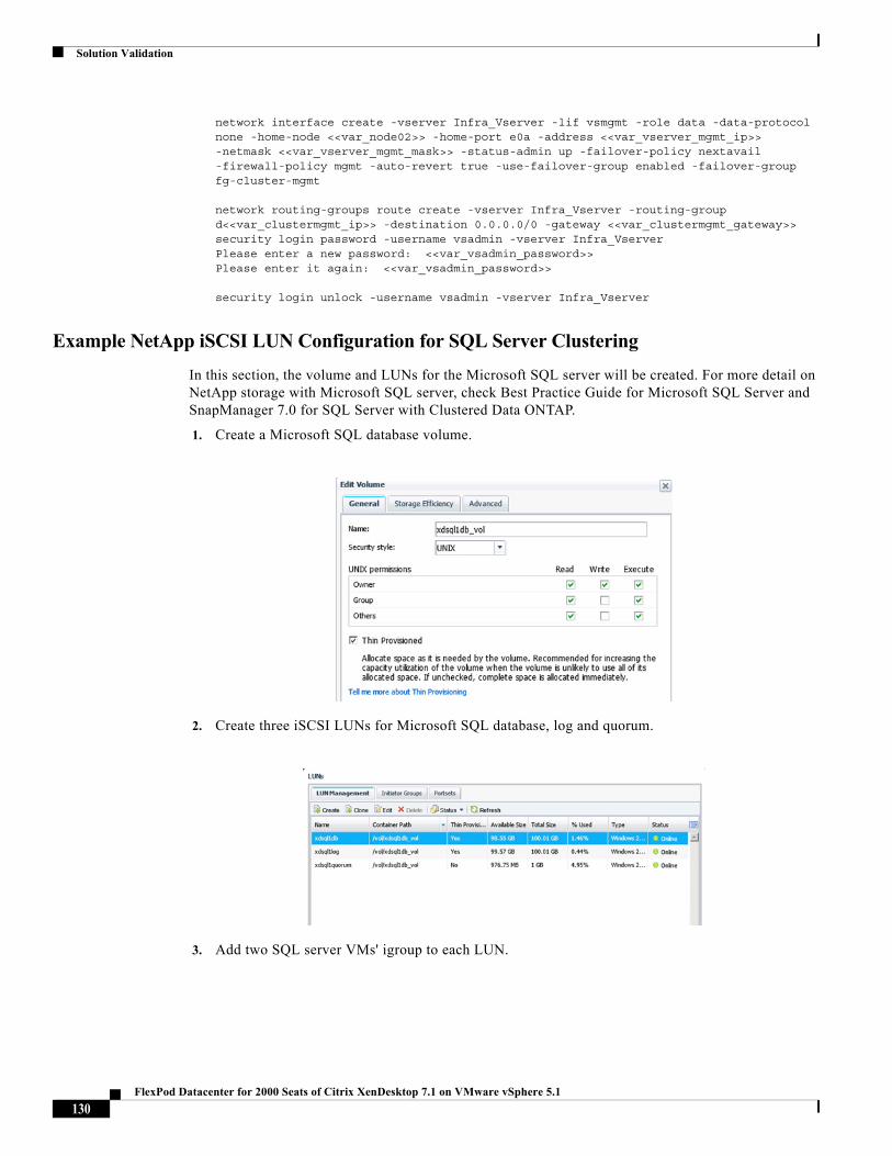
Solution Validation
network interface create -vserver Infra_Vserver -lif vsmgmt -role data -data-protocol none -home-node <<var_node02>> -home-port e0a -address <<var_vserver_mgmt_ip>> -netmask <<var_vserver_mgmt_mask>> -status-admin up -failover-policy nextavail -firewall-policy mgmt -auto-revert true -use-failover-group enabled -failover-group fg-cluster-mgmt
network routing-groups route create -vserver Infra_Vserver -routing-group d<<var_clustermgmt_ip>> -destination 0.0.0.0/0 -gateway <<var_clustermgmt_gateway>>security login password -username vsadmin -vserver Infra_VserverPlease enter a new password: <<var_vsadmin_password>>Please enter it again: <<var_vsadmin_password>>
security login unlock -username vsadmin -vserver Infra_Vserver
Example NetApp iSCSI LUN Configuration for SQL Server Clustering
In this section, the volume and LUNs for the Microsoft SQL server will be created. For more detail on NetApp storage with Microsoft SQL server, check Best Practice Guide for Microsoft SQL Server and SnapManager 7.0 for SQL Server with Clustered Data ONTAP.
1. Create a Microsoft SQL database volume.
2. Create three iSCSI LUNs for Microsoft SQL database, log and quorum.
3. Add two SQL server VMs' igroup to each LUN.
130FlexPod Datacenter for 2000 Seats of Citrix XenDesktop 7.1 on VMware vSphere 5.1
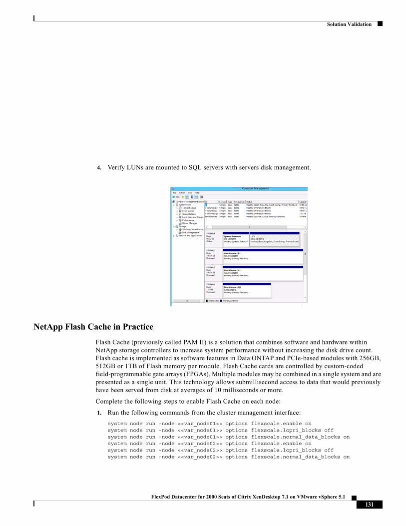
Solution Validation
4. Verify LUNs are mounted to SQL servers with servers disk management.
NetApp Flash Cache in Practice
Flash Cache (previously called PAM II) is a solution that combines software and hardware within NetApp storage controllers to increase system performance without increasing the disk drive count. Flash cache is implemented as software features in Data ONTAP and PCIe-based modules with 256GB, 512GB or 1TB of Flash memory per module. Flash Cache cards are controlled by custom-coded field-programmable gate arrays (FPGAs). Multiple modules may be combined in a single system and are presented as a single unit. This technology allows submillisecond access to data that would previously have been served from disk at averages of 10 milliseconds or more.
Complete the following steps to enable Flash Cache on each node:
1. Run the following commands from the cluster management interface:
system node run -node <<var_node01>> options flexscale.enable onsystem node run -node <<var_node01>> options flexscale.lopri_blocks offsystem node run -node <<var_node01>> options flexscale.normal_data_blocks onsystem node run -node <<var_node02>> options flexscale.enable onsystem node run -node <<var_node02>> options flexscale.lopri_blocks offsystem node run -node <<var_node02>> options flexscale.normal_data_blocks on
131FlexPod Datacenter for 2000 Seats of Citrix XenDesktop 7.1 on VMware vSphere 5.1
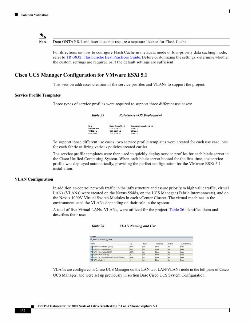
Solution Validation
Note Data ONTAP 8.1 and later does not require a separate license for Flash Cache.
For directions on how to configure Flash Cache in metadata mode or low-priority data caching mode, refer to TR-3832: Flash Cache Best Practices Guide. Before customizing the settings, determine whether the custom settings are required or if the default settings are sufficient.
Cisco UCS Manager Configuration for VMware ESXi 5.1
This section addresses creation of the service profiles and VLANs to support the project.
Service Profile Templates
Three types of service profiles were required to support three different use cases:
Table 25 Role/Server/OS Deployment
To support those different use cases, two service profile templates were created for each use case, one for each fabric utilizing various policies created earlier.
The service profile templates were then used to quickly deploy service profiles for each blade server in the Cisco Unified Computing System. When each blade server booted for the first time, the service profile was deployed automatically, providing the perfect configuration for the VMware ESXi 5.1 installation.
VLAN Configuration
In addition, to control network traffic in the infrastructure and assure priority to high value traffic, virtual LANs (VLANs) were created on the Nexus 5548s, on the UCS Manager (Fabric Interconnects), and on the Nexus 1000V Virtual Switch Modules in each vCenter Cluster. The virtual machines in the environment used the VLANs depending on their role in the system.
A total of five Virtual LANs, VLANs, were utilized for the project. Table 26 identifies them and describes their use:
Table 26 VLAN Naming and Use
VLANs are configured in Cisco UCS Manager on the LAN tab; LAN\VLANs node in the left pane of Cisco
UCS Manager, and were set up previously in section Base Cisco UCS System Configuration.
132FlexPod Datacenter for 2000 Seats of Citrix XenDesktop 7.1 on VMware vSphere 5.1
Solution Validation
Installing and Configuring ESXi 5.1
This section provides detailed instructions for installing VMware ESXi 5.1 in a FlexPod environment. After the procedures are completed, two FCP-booted ESXi hosts will be provisioned. These deployment procedures are customized to include the environment variables.
Note Several methods exist for installing ESXi in a VMware environment. These procedures focus on how to use the built-in Keyboard, Video, Mouse (KVM) console and virtual media features in Cisco UCS Manager to map remote installation media to individual servers and connect to their Fibre Channel Protocol (FCP) boot logical unit numbers (LUNs).
InstallingandConfiguringESXi5.1
Log in to Cisco UCS 6200 Fabric Interconnect
Cisco UCS Manager
The IP KVM enables the administrator to begin the installation of the operating system (OS) through remote
media. It is necessary to log in to the Cisco UCS environment to run the IP KVM.
To log in to the Cisco UCS environment, complete the following steps:
1. Open a Web browser and enter the IP address for the Cisco UCS cluster address. This step launches the Cisco UCS Manager application.
2. Log in to Cisco UCS Manager by using the admin user name and password.
3. From the main menu, click the Servers tab.
4. Select Servers > Service Profiles > root > VM-Host-Infra-01.
5. Right-click VM-Host-Infra-01 and select KVM Console.
6. Select Servers > Service Profiles > root > VM-Host-Infra-02.
7. Right-click VM-Host-Infra-02 and select KVM Console Actions > KVM Console.
Set Up VMware ESXi Installation
ESXi Hosts VM-Host-Infra-01 and VM-Host-Infra-02
To prepare the server for the OS installation, complete the following steps on each ESXi host:
1. In the KVM window, click the Virtual Media tab.
2. Click Add Image.
3. Browse to the ESXi installer ISO image file and click Open.
4. Select the Mapped checkbox to map the newly added image.
5. Click the KVM tab to monitor the server boot.
6. Boot the server by selecting Boot Server and clicking OK. Click OK.
133FlexPod Datacenter for 2000 Seats of Citrix XenDesktop 7.1 on VMware vSphere 5.1
Solution Validation
Install ESXi
To install VMware ESXi to the SAN-bootable LUN of the hosts, complete the following steps on each host:
1. On reboot, the machine detects the presence of the ESXi installation media. Select the ESXi installer from the menu that is displayed.
2. After the installer is finished loading, press Enter to continue with the installation.
3. Read and accept the end-user license agreement (EULA). Press F11 to accept and continue.
4. Select the NetApp LUN that was previously set up as the installation disk for ESXi and press Enter to continue with the installation.
5. Select the appropriate keyboard layout and press Enter.
6. Enter and confirm the root password and press Enter.
7. The installer issues a warning that existing partitions will be removed from the volume. Press F11 to continue with the installation.
8. After the installation is complete, clear the Mapped checkbox (located in the Virtual Media tab of the KVM console) to unmap the ESXi installation image.
Note The ESXi installation image must be unmapped to make sure that the server reboots into ESXi and not into the installer.
9. The Virtual Media window might issue a warning stating that it is preferable to eject the media from the guest. Because the media cannot be ejected and it is read-only, simply click Yes to unmap the image.
10. From the KVM tab, press Enter to reboot the server.
Set Up Management Networking for ESXi Hosts
Adding a management network for each VMware host is necessary for managing the host.
To configure the ESXi host with access to the management network, complete the following steps:
1. After the server has finished rebooting, press F2 to customize the system.
2. Log in as root and enter the corresponding password.
3. Select the Configure the Management Network option and press Enter.
4. Select the VLAN (Optional) option and press Enter.
5. Enter the <<var_ib-mgmt_vlan_id>> and press Enter.
6. From the Configure Management Network menu, select IP Configuration and press Enter.
7. Select the Set Static IP Address and Network Configuration option by using the space bar.
8. Enter the IP address for managing the first ESXi host: <<var_vm_host_infra_01_ip>>.
9. Enter the subnet mask for the first ESXi host.
10. Enter the default gateway for the first ESXi host.
11. Press Enter to accept the changes to the IP configuration.
12. Select the IPv6 Configuration option and press Enter.
13. Using the spacebar, unselect Enable IPv6 (restart required) and press Enter.
134FlexPod Datacenter for 2000 Seats of Citrix XenDesktop 7.1 on VMware vSphere 5.1
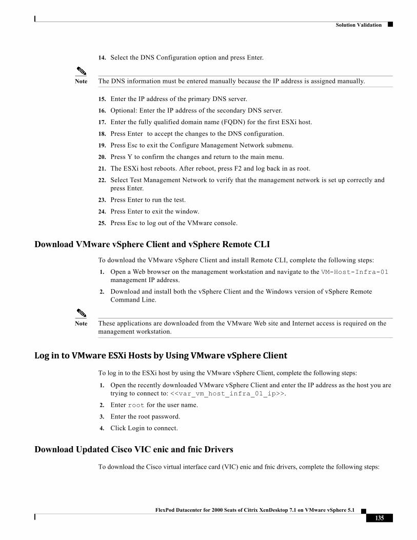
Solution Validation
14. Select the DNS Configuration option and press Enter.
Note The DNS information must be entered manually because the IP address is assigned manually.
15. Enter the IP address of the primary DNS server.
16. Optional: Enter the IP address of the secondary DNS server.
17. Enter the fully qualified domain name (FQDN) for the first ESXi host.
18. Press Enter to accept the changes to the DNS configuration.
19. Press Esc to exit the Configure Management Network submenu.
20. Press Y to confirm the changes and return to the main menu.
21. The ESXi host reboots. After reboot, press F2 and log back in as root.
22. Select Test Management Network to verify that the management network is set up correctly and press Enter.
23. Press Enter to run the test.
24. Press Enter to exit the window.
25. Press Esc to log out of the VMware console.
Download VMware vSphere Client and vSphere Remote CLI
To download the VMware vSphere Client and install Remote CLI, complete the following steps:
1. Open a Web browser on the management workstation and navigate to the VM-Host-Infra-01 management IP address.
2. Download and install both the vSphere Client and the Windows version of vSphere Remote Command Line.
Note These applications are downloaded from the VMware Web site and Internet access is required on the management workstation.
LogintoVMwareESXiHostsbyUsingVMwarevSphereClient
To log in to the ESXi host by using the VMware vSphere Client, complete the following steps:
1. Open the recently downloaded VMware vSphere Client and enter the IP address as the host you are trying to connect to: <<var_vm_host_infra_01_ip>>.
2. Enter root for the user name.
3. Enter the root password.
4. Click Login to connect.
Download Updated Cisco VIC enic and fnic Drivers
To download the Cisco virtual interface card (VIC) enic and fnic drivers, complete the following steps:
135FlexPod Datacenter for 2000 Seats of Citrix XenDesktop 7.1 on VMware vSphere 5.1
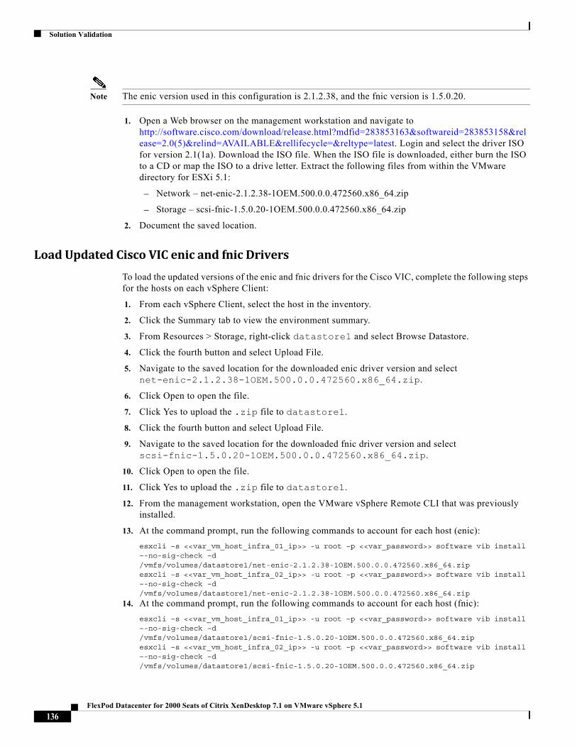
Solution Validation
Note The enic version used in this configuration is 2.1.2.38, and the fnic version is 1.5.0.20.
1. Open a Web browser on the management workstation and navigate to http://software.cisco.com/download/release.html?mdfid=283853163&softwareid=283853158&release=2.0(5)&relind=AVAILABLE&rellifecycle=&reltype=latest. Login and select the driver ISO for version 2.1(1a). Download the ISO file. When the ISO file is downloaded, either burn the ISO to a CD or map the ISO to a drive letter. Extract the following files from within the VMware directory for ESXi 5.1:
– Network – net-enic-2.1.2.38-1OEM.500.0.0.472560.x86_64.zip
– Storage – scsi-fnic-1.5.0.20-1OEM.500.0.0.472560.x86_64.zip
2. Document the saved location.
LoadUpdatedCiscoVICenicandfnicDrivers
To load the updated versions of the enic and fnic drivers for the Cisco VIC, complete the following steps for the hosts on each vSphere Client:
1. From each vSphere Client, select the host in the inventory.
2. Click the Summary tab to view the environment summary.
3. From Resources > Storage, right-click datastore1 and select Browse Datastore.
4. Click the fourth button and select Upload File.
5. Navigate to the saved location for the downloaded enic driver version and select net-enic-2.1.2.38-1OEM.500.0.0.472560.x86_64.zip.
6. Click Open to open the file.
7. Click Yes to upload the .zip file to datastore1.
8. Click the fourth button and select Upload File.
9. Navigate to the saved location for the downloaded fnic driver version and select scsi-fnic-1.5.0.20-1OEM.500.0.0.472560.x86_64.zip.
10. Click Open to open the file.
11. Click Yes to upload the .zip file to datastore1.
12. From the management workstation, open the VMware vSphere Remote CLI that was previously installed.
13. At the command prompt, run the following commands to account for each host (enic):
esxcli –s <<var_vm_host_infra_01_ip>> -u root –p <<var_password>> software vib install –-no-sig-check –d /vmfs/volumes/datastore1/net-enic-2.1.2.38-1OEM.500.0.0.472560.x86_64.zipesxcli –s <<var_vm_host_infra_02_ip>> -u root –p <<var_password>> software vib install –-no-sig-check –d /vmfs/volumes/datastore1/net-enic-2.1.2.38-1OEM.500.0.0.472560.x86_64.zip
14. At the command prompt, run the following commands to account for each host (fnic):
esxcli –s <<var_vm_host_infra_01_ip>> -u root –p <<var_password>> software vib install –-no-sig-check –d /vmfs/volumes/datastore1/scsi-fnic-1.5.0.20-1OEM.500.0.0.472560.x86_64.zipesxcli –s <<var_vm_host_infra_02_ip>> -u root –p <<var_password>> software vib install –-no-sig-check –d /vmfs/volumes/datastore1/scsi-fnic-1.5.0.20-1OEM.500.0.0.472560.x86_64.zip
136FlexPod Datacenter for 2000 Seats of Citrix XenDesktop 7.1 on VMware vSphere 5.1
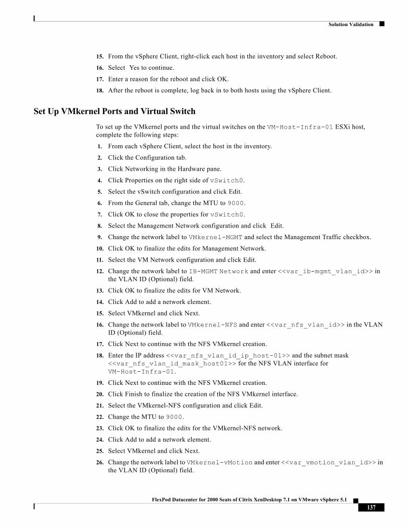
Solution Validation
15. From the vSphere Client, right-click each host in the inventory and select Reboot.
16. Select Yes to continue.
17. Enter a reason for the reboot and click OK.
18. After the reboot is complete, log back in to both hosts using the vSphere Client.
Set Up VMkernel Ports and Virtual Switch
To set up the VMkernel ports and the virtual switches on the VM-Host-Infra-01 ESXi host, complete the following steps:
1. From each vSphere Client, select the host in the inventory.
2. Click the Configuration tab.
3. Click Networking in the Hardware pane.
4. Click Properties on the right side of vSwitch0.
5. Select the vSwitch configuration and click Edit.
6. From the General tab, change the MTU to 9000.
7. Click OK to close the properties for vSwitch0.
8. Select the Management Network configuration and click Edit.
9. Change the network label to VMkernel-MGMT and select the Management Traffic checkbox.
10. Click OK to finalize the edits for Management Network.
11. Select the VM Network configuration and click Edit.
12. Change the network label to IB-MGMT Network and enter <<var_ib-mgmt_vlan_id>> in the VLAN ID (Optional) field.
13. Click OK to finalize the edits for VM Network.
14. Click Add to add a network element.
15. Select VMkernel and click Next.
16. Change the network label to VMkernel-NFS and enter <<var_nfs_vlan_id>> in the VLAN ID (Optional) field.
17. Click Next to continue with the NFS VMkernel creation.
18. Enter the IP address <<var_nfs_vlan_id_ip_host-01>> and the subnet mask <<var_nfs_vlan_id_mask_host01>> for the NFS VLAN interface for VM-Host-Infra-01.
19. Click Next to continue with the NFS VMkernel creation.
20. Click Finish to finalize the creation of the NFS VMkernel interface.
21. Select the VMkernel-NFS configuration and click Edit.
22. Change the MTU to 9000.
23. Click OK to finalize the edits for the VMkernel-NFS network.
24. Click Add to add a network element.
25. Select VMkernel and click Next.
26. Change the network label to VMkernel-vMotion and enter <<var_vmotion_vlan_id>> in the VLAN ID (Optional) field.
137FlexPod Datacenter for 2000 Seats of Citrix XenDesktop 7.1 on VMware vSphere 5.1
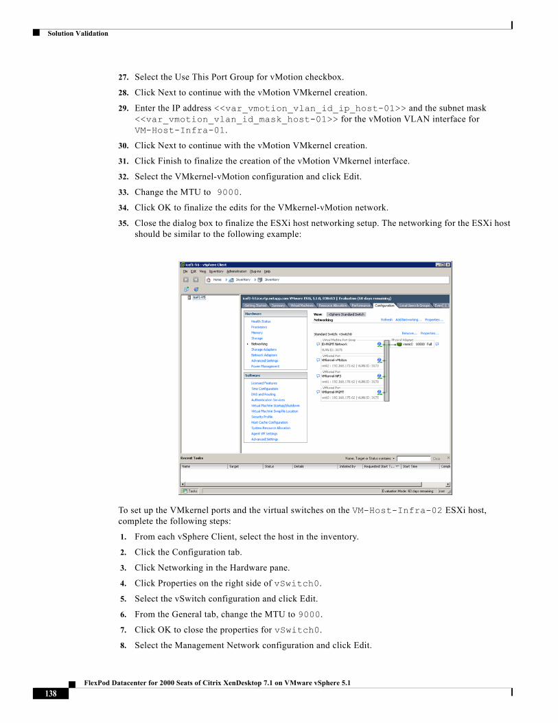
Solution Validation
27. Select the Use This Port Group for vMotion checkbox.
28. Click Next to continue with the vMotion VMkernel creation.
29. Enter the IP address <<var_vmotion_vlan_id_ip_host-01>> and the subnet mask <<var_vmotion_vlan_id_mask_host-01>> for the vMotion VLAN interface for VM-Host-Infra-01.
30. Click Next to continue with the vMotion VMkernel creation.
31. Click Finish to finalize the creation of the vMotion VMkernel interface.
32. Select the VMkernel-vMotion configuration and click Edit.
33. Change the MTU to 9000.
34. Click OK to finalize the edits for the VMkernel-vMotion network.
35. Close the dialog box to finalize the ESXi host networking setup. The networking for the ESXi host should be similar to the following example:
To set up the VMkernel ports and the virtual switches on the VM-Host-Infra-02 ESXi host, complete the following steps:
1. From each vSphere Client, select the host in the inventory.
2. Click the Configuration tab.
3. Click Networking in the Hardware pane.
4. Click Properties on the right side of vSwitch0.
5. Select the vSwitch configuration and click Edit.
6. From the General tab, change the MTU to 9000.
7. Click OK to close the properties for vSwitch0.
8. Select the Management Network configuration and click Edit.
138FlexPod Datacenter for 2000 Seats of Citrix XenDesktop 7.1 on VMware vSphere 5.1
Solution Validation
9. Change the network label to VMkernel-MGMT and select the Management Traffic checkbox.
10. Click OK to finalize the edits for the Management Network.
11. Select the VM Network configuration and click Edit.
12. Change the network label to IB-MGMT Network and enter <<var_ib-mgmt_vlan_id>> in the VLAN ID (Optional) field.
13. Click OK to finalize the edits for the VM Network.
14. Click Add to add a network element.
15. Select VMkernel and click Next.
16. Change the network label to VMkernel-NFS and enter <<var_nfs_vlan_id>> in the VLAN ID (Optional) field.
17. Click Next to continue with the NFS VMkernel creation.
18. Enter the IP address <<var_nfs_vlan_id_ip_host-02>> and the subnet mask <<var_nfs_vlan_id_mask_host-02>> for the NFS VLAN interface for VM-Host-Infra-02.
19. Click Next to continue with the NFS VMkernel creation.
20. Click Finish to finalize the creation of the NFS VMkernel interface.
21. Select the VMkernel-NFS configuration and click Edit.
22. Change the MTU to 9000.
23. Click OK to finalize the edits for the VMkernel-NFS network.
24. Click Add to add a network element.
25. Select VMkernel and click Next.
26. Change the network label to VMkernel-vMotion and enter <<var_vmotion_vlan_id>> in the VLAN ID (Optional) field.
27. Select the Use This Port Group for vMotion checkbox.
28. Click Next to continue with the vMotion VMkernel creation.
29. Enter the IP address <<var_vmotion_vlan_id_ip_host-02>> and the subnet mask <<var_vmotion_vlan_id_mask_host-02>> for the vMotion VLAN interface for VM-Host-Infra-02.
30. Click Next to continue with the vMotion VMkernel creation.
31. Click Finish to finalize the creation of the vMotion VMkernel interface.
32. Select the VMkernel-vMotion configuration and click Edit.
33. Change the MTU to 9000.
34. Click OK to finalize the edits for the VMkernel-vMotion network.
35. Close the dialog box to finalize the ESXi host networking setup. The networking for the ESXi host should be similar to the following example:
139FlexPod Datacenter for 2000 Seats of Citrix XenDesktop 7.1 on VMware vSphere 5.1
Solution Validation
Mount Required Datastores
To mount the required datastores, complete the following steps on each ESXi host:
1. From each vSphere Client, select the host in the inventory.
2. Click the Configuration tab to enable configurations.
3. Click Storage in the Hardware pane.
4. From the Datastore area, click Add Storage to open the Add Storage wizard.
5. Select Network File System and click Next.
6. The wizard prompts for the location of the NFS export. Enter <<var_nfs_lif02_ip>> as the IP address for nfs_lif02.
7. Enter /infra_datastore_1 as the path for the NFS export.
8. Make sure that the Mount NFS read only checkbox is NOT selected.
9. Enter infra_datastore_1 as the datastore name.
10. Click Next to continue with the NFS datastore creation.
11. Click Finish to finalize the creation of the NFS datastore.
12. From the Datastore area, click Add Storage to open the Add Storage wizard.
13. Select Network File System and click Next.
14. The wizard prompts for the location of the NFS export. Enter <<var_nfs_lif01_ip>> as the IP address for nfs_lif01.
15. Enter /infra_swap as the path for the NFS export.
16. Make sure that the Mount NFS read only checkbox is NOT selected.
140FlexPod Datacenter for 2000 Seats of Citrix XenDesktop 7.1 on VMware vSphere 5.1
Solution Validation
17. Enter infra_swap as the datastore name.
18. Click Next to continue with the NFS datastore creation.
19. Click Finish to finalize the creation of the NFS datastore.
ConfigureNTPonESXiHosts
To configure Network Time Protocol (NTP) on the ESXi hosts, complete the following steps on each host:
1. From each vSphere Client, select the host in the inventory.
2. Click the Configuration tab to enable configurations.
3. Click Time Configuration in the Software pane.
4. Click Properties at the upper right side of the window.
5. At the bottom of the Time Configuration dialog box, click Options.
6. In the NTP Daemon Options dialog box, complete the following steps:
– Click General in the left pane and select Start and stop with host.
– Click NTP Settings in the left pane and click Add.
7. In the Add NTP Server dialog box, enter <<var_global_ntp_server_ip>> as the IP address of the NTP server and click OK.
8. In the NTP Daemon Options dialog box, select the Restart NTP Service to Apply Changes checkbox and click OK.
9. In the Time Configuration dialog box, complete the following steps:
– Select the NTP Client Enabled checkbox and click OK.
– Verify that the clock is now set to approximately the correct time.
Note The NTP server time may vary slightly from the host time.
Move VM Swap File Location
To move the VM swap file location, complete the following steps on each ESXi host:
1. From each vSphere Client, select the host in the inventory.
2. Click the Configuration tab to enable configurations.
3. Click Virtual Machine Swapfile Location in the Software pane.
4. Click Edit at the upper right side of the window.
5. Select Store the swapfile in a swapfile datastore selected below.
6. Select infra_swap as the datastore in which to house the swap files.
7. Click OK to finalize moving the swap file location.
141FlexPod Datacenter for 2000 Seats of Citrix XenDesktop 7.1 on VMware vSphere 5.1
Solution Validation
Install and Configure Virtual Center 5.1
The procedures in the following subsections provide detailed instructions for installing VMware vCenter 5.1 in a FlexPod environment. After the procedures are completed, a VMware vCenter Server will be configured along with a Microsoft SQL Server database to provide database support to vCenter. These deployment procedures are customized to include the environment variables.
Note This procedure focuses on the installation and configuration of an external Microsoft SQL Server 2008 R2 database, but other types of external databases are also supported by vCenter. To use an alternative database, refer to the VMware vSphere 5.1 documentation for information about how to configure the database and integrate it into vCenter.
To install VMware vCenter 5.1, an accessible Windows Active Directory® (AD) Domain is necessary. If an existing AD Domain is not available, an AD virtual machine, or AD pair, can be set up in this FlexPod environment.
Build Microsoft SQL Server VM
To build a SQL Server virtual machine (VM) for the VM-Host-Infra-01 ESXi host, complete the following steps:
1. Log in to the host by using the VMware vSphere Client.
2. In the vSphere Client, select the host in the inventory pane.
3. Right-click the host and select New Virtual Machine.
4. Select Custom and click Next.
5. Enter a name for the VM. Click Next.
6. Select infra_datastore_1. Click Next.
7. Select Virtual Machine Version: 8. Click Next.
8. Verify that the Windows option and the Microsoft Windows Server 2008 R2 (64-bit) version are selected. Click Next.
9. Select two virtual sockets and one core per virtual socket. Click Next.
10. Select 4GB of memory. Click Next.
11. Select one network interface card (NIC).
12. For NIC 1, select the IB-MGMT Network option and the VMXNET 3 adapter. Click Next.
13. Keep the LSI Logic SAS option for the SCSI controller selected. Click Next.
14. Keep the Create a New Virtual Disk option selected. Click Next.
15. Make the disk size at least 60GB. Click Next.
16. Click Next.
17. Select the checkbox for Edit the Virtual Machine Settings Before Completion. Click Continue.
18. Click the Options tab.
19. Select Boot Options.
20. Select the Force BIOS Setup checkbox.
21. Click Finish.
142FlexPod Datacenter for 2000 Seats of Citrix XenDesktop 7.1 on VMware vSphere 5.1
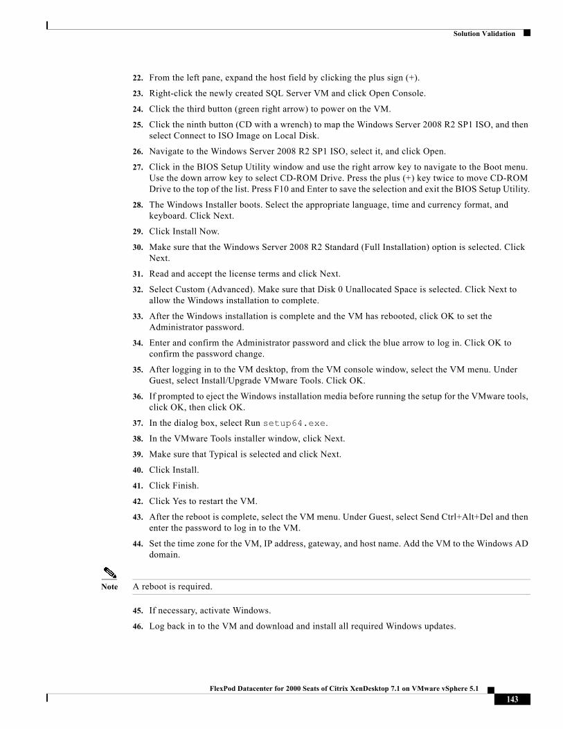
Solution Validation
22. From the left pane, expand the host field by clicking the plus sign (+).
23. Right-click the newly created SQL Server VM and click Open Console.
24. Click the third button (green right arrow) to power on the VM.
25. Click the ninth button (CD with a wrench) to map the Windows Server 2008 R2 SP1 ISO, and then select Connect to ISO Image on Local Disk.
26. Navigate to the Windows Server 2008 R2 SP1 ISO, select it, and click Open.
27. Click in the BIOS Setup Utility window and use the right arrow key to navigate to the Boot menu. Use the down arrow key to select CD-ROM Drive. Press the plus (+) key twice to move CD-ROM Drive to the top of the list. Press F10 and Enter to save the selection and exit the BIOS Setup Utility.
28. The Windows Installer boots. Select the appropriate language, time and currency format, and keyboard. Click Next.
29. Click Install Now.
30. Make sure that the Windows Server 2008 R2 Standard (Full Installation) option is selected. Click Next.
31. Read and accept the license terms and click Next.
32. Select Custom (Advanced). Make sure that Disk 0 Unallocated Space is selected. Click Next to allow the Windows installation to complete.
33. After the Windows installation is complete and the VM has rebooted, click OK to set the Administrator password.
34. Enter and confirm the Administrator password and click the blue arrow to log in. Click OK to confirm the password change.
35. After logging in to the VM desktop, from the VM console window, select the VM menu. Under Guest, select Install/Upgrade VMware Tools. Click OK.
36. If prompted to eject the Windows installation media before running the setup for the VMware tools, click OK, then click OK.
37. In the dialog box, select Run setup64.exe.
38. In the VMware Tools installer window, click Next.
39. Make sure that Typical is selected and click Next.
40. Click Install.
41. Click Finish.
42. Click Yes to restart the VM.
43. After the reboot is complete, select the VM menu. Under Guest, select Send Ctrl+Alt+Del and then enter the password to log in to the VM.
44. Set the time zone for the VM, IP address, gateway, and host name. Add the VM to the Windows AD domain.
Note A reboot is required.
45. If necessary, activate Windows.
46. Log back in to the VM and download and install all required Windows updates.
143FlexPod Datacenter for 2000 Seats of Citrix XenDesktop 7.1 on VMware vSphere 5.1
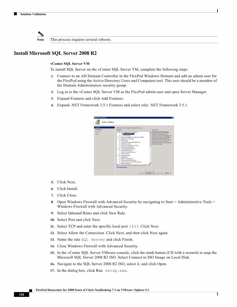
Solution Validation
Note This process requires several reboots.
Install Microsoft SQL Server 2008 R2
vCenter SQL Server VM
To install SQL Server on the vCenter SQL Server VM, complete the following steps:
1. Connect to an AD Domain Controller in the FlexPod Windows Domain and add an admin user for the FlexPod using the Active Directory Users and Computers tool. This user should be a member of the Domain Administrators security group.
2. Log in to the vCenter SQL Server VM as the FlexPod admin user and open Server Manager.
3. Expand Features and click Add Features.
4. Expand .NET Framework 3.5.1 Features and select only .NET Framework 3.5.1.
5. Click Next.
6. Click Install.
7. Click Close.
8. Open Windows Firewall with Advanced Security by navigating to Start > Administrative Tools > Windows Firewall with Advanced Security.
9. Select Inbound Rules and click New Rule.
10. Select Port and click Next.
11. Select TCP and enter the specific local port 1433. Click Next.
12. Select Allow the Connection. Click Next, and then click Next again.
13. Name the rule SQL Server and click Finish.
14. Close Windows Firewall with Advanced Security.
15. In the vCenter SQL Server VMware console, click the ninth button (CD with a wrench) to map the Microsoft SQL Server 2008 R2 ISO. Select Connect to ISO Image on Local Disk.
16. Navigate to the SQL Server 2008 R2 ISO, select it, and click Open.
17. In the dialog box, click Run setup.exe.
144FlexPod Datacenter for 2000 Seats of Citrix XenDesktop 7.1 on VMware vSphere 5.1
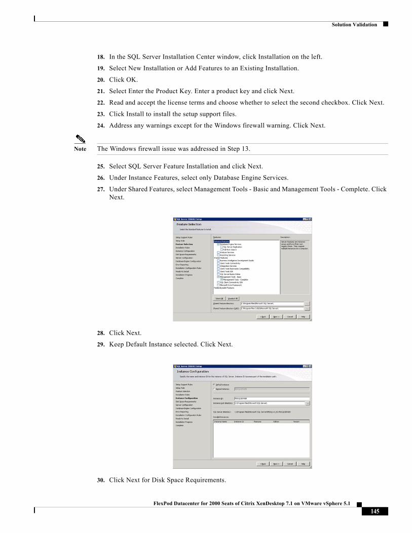
Solution Validation
18. In the SQL Server Installation Center window, click Installation on the left.
19. Select New Installation or Add Features to an Existing Installation.
20. Click OK.
21. Select Enter the Product Key. Enter a product key and click Next.
22. Read and accept the license terms and choose whether to select the second checkbox. Click Next.
23. Click Install to install the setup support files.
24. Address any warnings except for the Windows firewall warning. Click Next.
Note The Windows firewall issue was addressed in Step 13.
25. Select SQL Server Feature Installation and click Next.
26. Under Instance Features, select only Database Engine Services.
27. Under Shared Features, select Management Tools - Basic and Management Tools - Complete. Click Next.
28. Click Next.
29. Keep Default Instance selected. Click Next.
30. Click Next for Disk Space Requirements.
145FlexPod Datacenter for 2000 Seats of Citrix XenDesktop 7.1 on VMware vSphere 5.1
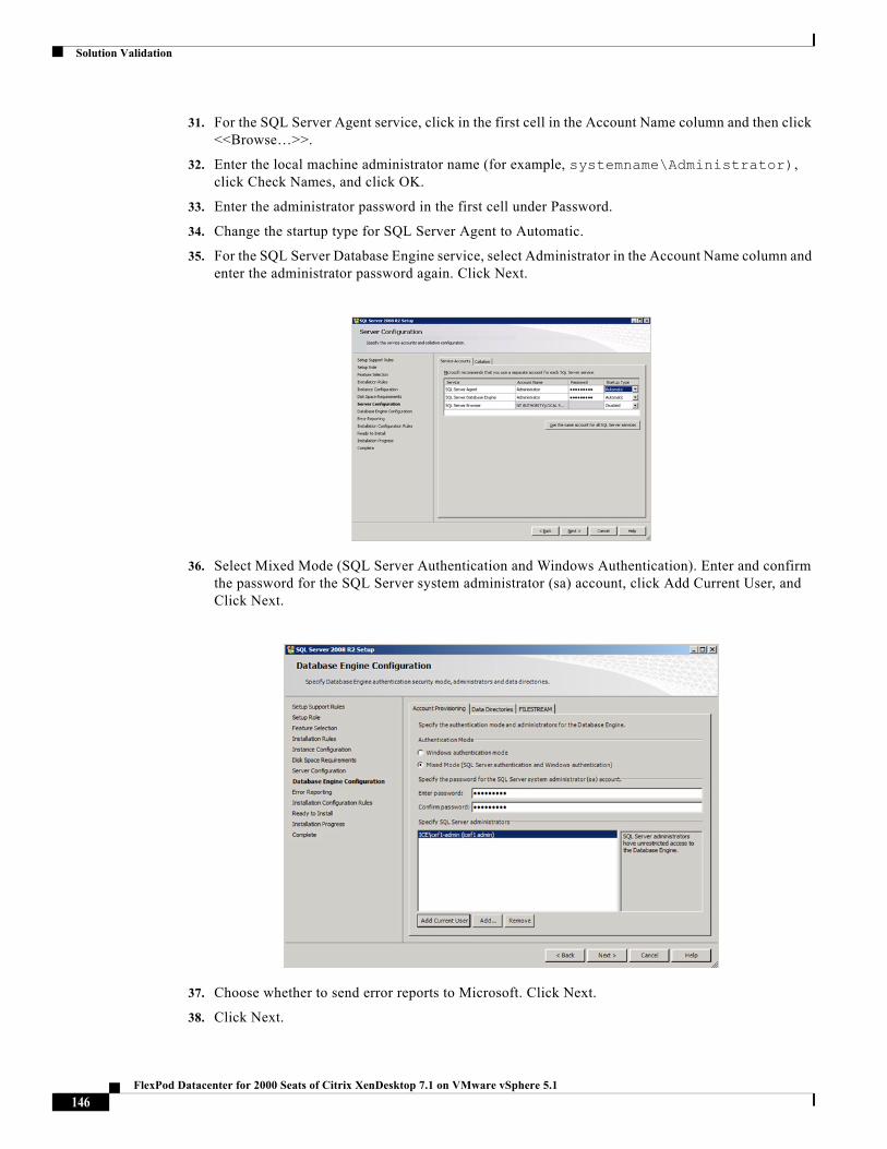
Solution Validation
31. For the SQL Server Agent service, click in the first cell in the Account Name column and then click <<Browse…>>.
32. Enter the local machine administrator name (for example, systemname\Administrator), click Check Names, and click OK.
33. Enter the administrator password in the first cell under Password.
34. Change the startup type for SQL Server Agent to Automatic.
35. For the SQL Server Database Engine service, select Administrator in the Account Name column and enter the administrator password again. Click Next.
36. Select Mixed Mode (SQL Server Authentication and Windows Authentication). Enter and confirm the password for the SQL Server system administrator (sa) account, click Add Current User, and Click Next.
37. Choose whether to send error reports to Microsoft. Click Next.
38. Click Next.
146FlexPod Datacenter for 2000 Seats of Citrix XenDesktop 7.1 on VMware vSphere 5.1
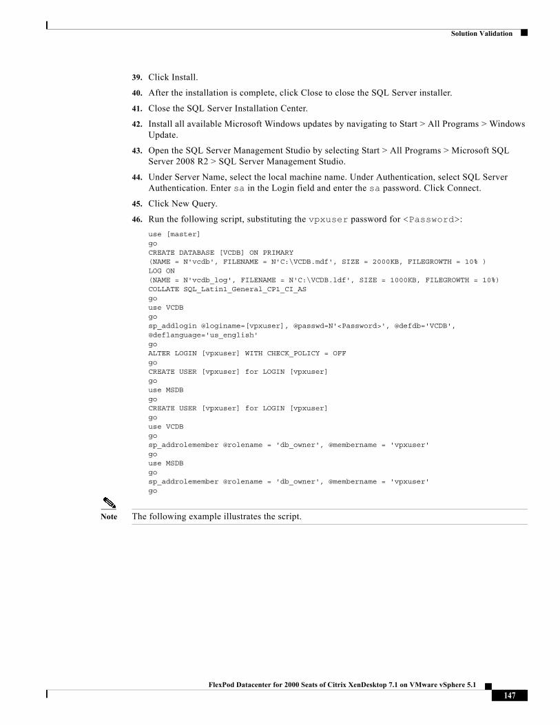
Solution Validation
39. Click Install.
40. After the installation is complete, click Close to close the SQL Server installer.
41. Close the SQL Server Installation Center.
42. Install all available Microsoft Windows updates by navigating to Start > All Programs > Windows Update.
43. Open the SQL Server Management Studio by selecting Start > All Programs > Microsoft SQL Server 2008 R2 > SQL Server Management Studio.
44. Under Server Name, select the local machine name. Under Authentication, select SQL Server Authentication. Enter sa in the Login field and enter the sa password. Click Connect.
45. Click New Query.
46. Run the following script, substituting the vpxuser password for <Password>:
use [master]goCREATE DATABASE [VCDB] ON PRIMARY(NAME = N'vcdb', FILENAME = N'C:\VCDB.mdf', SIZE = 2000KB, FILEGROWTH = 10% )LOG ON(NAME = N'vcdb_log', FILENAME = N'C:\VCDB.ldf', SIZE = 1000KB, FILEGROWTH = 10%)COLLATE SQL_Latin1_General_CP1_CI_ASgouse VCDBgosp_addlogin @loginame=[vpxuser], @passwd=N'<Password>', @defdb='VCDB',@deflanguage='us_english'goALTER LOGIN [vpxuser] WITH CHECK_POLICY = OFFgoCREATE USER [vpxuser] for LOGIN [vpxuser]gouse MSDBgoCREATE USER [vpxuser] for LOGIN [vpxuser]gouse VCDBgosp_addrolemember @rolename = 'db_owner', @membername = 'vpxuser'gouse MSDBgosp_addrolemember @rolename = 'db_owner', @membername = 'vpxuser'go
Note The following example illustrates the script.
147FlexPod Datacenter for 2000 Seats of Citrix XenDesktop 7.1 on VMware vSphere 5.1
Solution Validation
47. Click Execute and verify that the query executes successfully.
48. Close Microsoft SQL Server Management Studio.
49. Disconnect the Microsoft SQL Server 2008 R2 ISO from the SQL Server VM.
Build and Set Up VMware vCenter VM
Build VMware vCenter VM
To build the VMware vCenter VM, complete the following steps:
1. Build a VMware vCenter VM with the following configuration in the <<var_ib-mgmt_vlan_id>> VLAN:
– 4GB RAM
– Two CPUs
– One virtual network interface
2. Start the VM, install VMware Tools, and assign an IP address and host name to it in the Active Directory domain.
Set Up VMware vCenter VM
To set up the newly built VMware vCenter VM, complete the following steps:
1. Log in to the vCenter VM as the FlexPod admin user and open Server Manager.
2. Expand Features and click Add Features.
3. Expand .NET Framework 3.5.1 Features and select only .NET Framework 3.5.1.
4. Click Next.
5. Click Install.
6. Click Close to close the Add Features wizard.
7. Close Server Manager.
8. Download and install the client components of the Microsoft SQL Server 2008 R2 Native Client from the Microsoft Download Center.
148FlexPod Datacenter for 2000 Seats of Citrix XenDesktop 7.1 on VMware vSphere 5.1
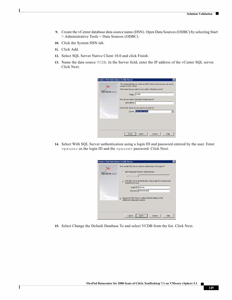
Solution Validation
9. Create the vCenter database data source name (DSN). Open Data Sources (ODBC) by selecting Start > Administrative Tools > Data Sources (ODBC).
10. Click the System DSN tab.
11. Click Add.
12. Select SQL Server Native Client 10.0 and click Finish.
13. Name the data source VCDB. In the Server field, enter the IP address of the vCenter SQL server. Click Next.
14. Select With SQL Server authentication using a login ID and password entered by the user. Enter vpxuser as the login ID and the vpxuser password. Click Next.
15. Select Change the Default Database To and select VCDB from the list. Click Next.
149FlexPod Datacenter for 2000 Seats of Citrix XenDesktop 7.1 on VMware vSphere 5.1
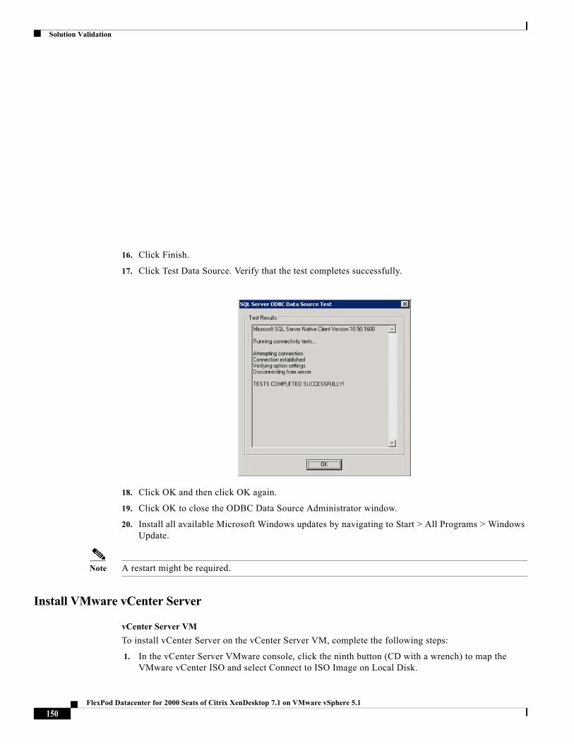
Solution Validation
16. Click Finish.
17. Click Test Data Source. Verify that the test completes successfully.
18. Click OK and then click OK again.
19. Click OK to close the ODBC Data Source Administrator window.
20. Install all available Microsoft Windows updates by navigating to Start > All Programs > Windows Update.
Note A restart might be required.
Install VMware vCenter Server
vCenter Server VM
To install vCenter Server on the vCenter Server VM, complete the following steps:
1. In the vCenter Server VMware console, click the ninth button (CD with a wrench) to map the VMware vCenter ISO and select Connect to ISO Image on Local Disk.
150FlexPod Datacenter for 2000 Seats of Citrix XenDesktop 7.1 on VMware vSphere 5.1
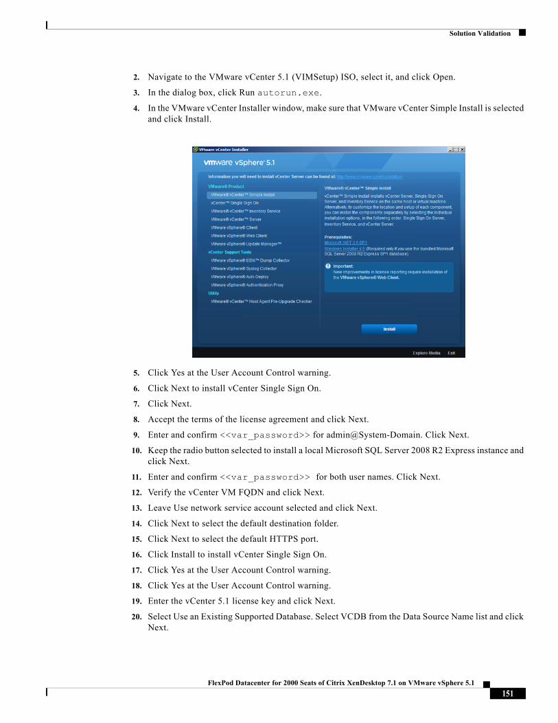
Solution Validation
2. Navigate to the VMware vCenter 5.1 (VIMSetup) ISO, select it, and click Open.
3. In the dialog box, click Run autorun.exe.
4. In the VMware vCenter Installer window, make sure that VMware vCenter Simple Install is selected and click Install.
5. Click Yes at the User Account Control warning.
6. Click Next to install vCenter Single Sign On.
7. Click Next.
8. Accept the terms of the license agreement and click Next.
9. Enter and confirm <<var_password>> for admin@System-Domain. Click Next.
10. Keep the radio button selected to install a local Microsoft SQL Server 2008 R2 Express instance and click Next.
11. Enter and confirm <<var_password>> for both user names. Click Next.
12. Verify the vCenter VM FQDN and click Next.
13. Leave Use network service account selected and click Next.
14. Click Next to select the default destination folder.
15. Click Next to select the default HTTPS port.
16. Click Install to install vCenter Single Sign On.
17. Click Yes at the User Account Control warning.
18. Click Yes at the User Account Control warning.
19. Enter the vCenter 5.1 license key and click Next.
20. Select Use an Existing Supported Database. Select VCDB from the Data Source Name list and click Next.
151FlexPod Datacenter for 2000 Seats of Citrix XenDesktop 7.1 on VMware vSphere 5.1
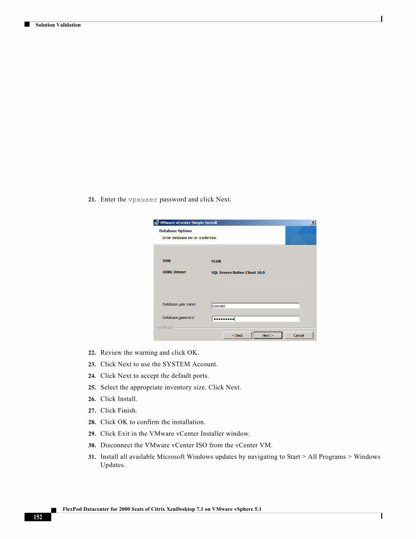
Solution Validation
21. Enter the vpxuser password and click Next.
22. Review the warning and click OK.
23. Click Next to use the SYSTEM Account.
24. Click Next to accept the default ports.
25. Select the appropriate inventory size. Click Next.
26. Click Install.
27. Click Finish.
28. Click OK to confirm the installation.
29. Click Exit in the VMware vCenter Installer window.
30. Disconnect the VMware vCenter ISO from the vCenter VM.
31. Install all available Microsoft Windows updates by navigating to Start > All Programs > Windows Updates.
152FlexPod Datacenter for 2000 Seats of Citrix XenDesktop 7.1 on VMware vSphere 5.1
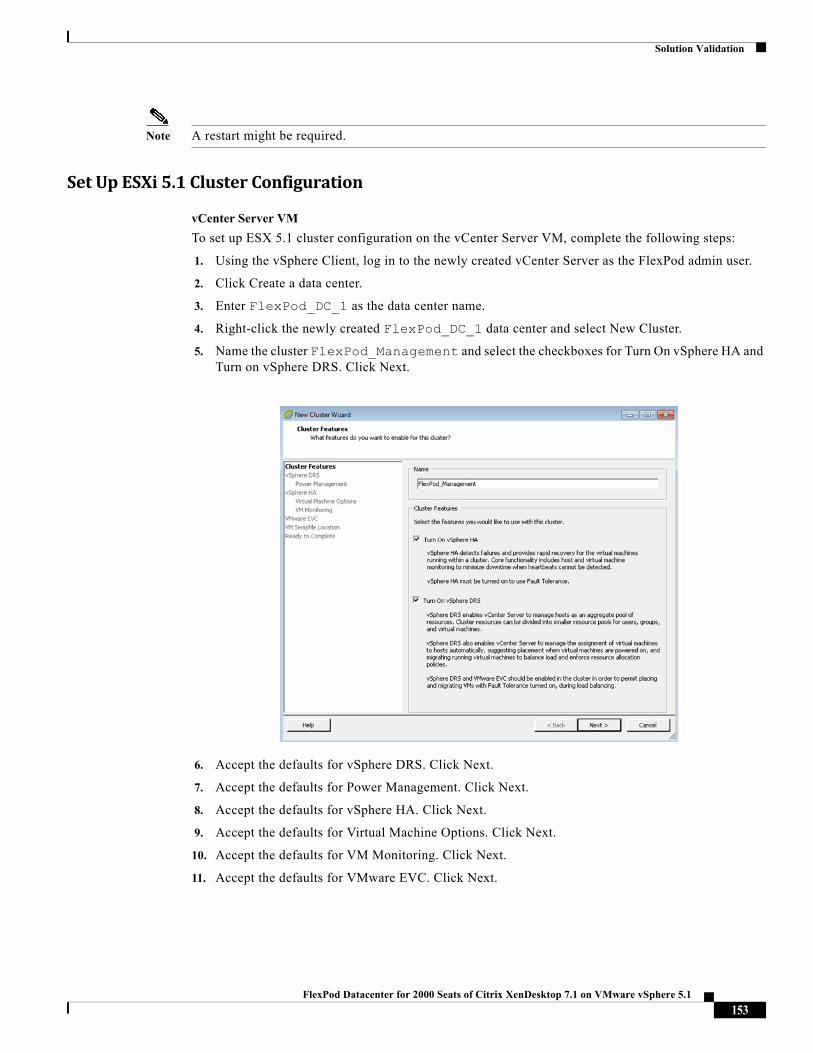
Solution Validation
Note A restart might be required.
SetUpESXi5.1ClusterConfiguration
vCenter Server VM
To set up ESX 5.1 cluster configuration on the vCenter Server VM, complete the following steps:
1. Using the vSphere Client, log in to the newly created vCenter Server as the FlexPod admin user.
2. Click Create a data center.
3. Enter FlexPod_DC_1 as the data center name.
4. Right-click the newly created FlexPod_DC_1 data center and select New Cluster.
5. Name the cluster FlexPod_Management and select the checkboxes for Turn On vSphere HA and Turn on vSphere DRS. Click Next.
6. Accept the defaults for vSphere DRS. Click Next.
7. Accept the defaults for Power Management. Click Next.
8. Accept the defaults for vSphere HA. Click Next.
9. Accept the defaults for Virtual Machine Options. Click Next.
10. Accept the defaults for VM Monitoring. Click Next.
11. Accept the defaults for VMware EVC. Click Next.
153FlexPod Datacenter for 2000 Seats of Citrix XenDesktop 7.1 on VMware vSphere 5.1
Solution Validation
Note If mixing Cisco UCS B or C-Series M2 and M3 servers within a vCenter cluster, it is necessary to enable VMware Enhanced vMotion Compatibility (EVC) mode. For more information about setting up EVC mode, refer to Enhanced vMotion Compatibility (EVC) Processor Support.
12. Select Store the swapfile in the datastore specified by the host. Click Next.
13. Click Finish.
14. Right-click the newly created FlexPod_Management cluster and select Add Host.
15. In the Host field, enter either the IP address or the host name of the VM-Host-Infra_01 host. Enter root as the user name and the root password for this host. Click Next.
16. Click Yes.
17. Click Next.
18. Select Assign a New License Key to the Host. Click Enter Key and enter a vSphere license key. Click OK, and then click Next.
19. Click Next.
20. Click Next.
21. Click Finish. VM-Host-Infra-01 is added to the cluster.
22. Repeat this procedure to add VM-Host-Infra-02 to the cluster.
23. Create two additional clusters named XenDesktopHVD and XenDesktopRDS.
24. Add hosts XenDesktopHVD-01 thru XenDesktopHVD-04 to the XenDesktopHVD cluster.
25. Add hosts XenDesktopRDS-01 thru XenDesktopRDS-08 to the XenDesktopRDS cluster.
Installing and Configuring Citrix XenDesktop and Provisioning Components
To prepare the required infrastructure to support the Citrix XenDesktop Hosted Virtual Desktop and Hosted Shared Desktop environment, the following procedures were followed.
Installing Citrix License Server
XenDesktop requires Citrix licensing to be installed. For this CVD, we implemented a dedicated server for licensing. If you already have an existing license server, then Citrix recommends that you upgrade it to the latest version when you upgrade or install new Citrix products. New license servers are backwards compatible and work with older products and license files. New products often require the newest license server to check out licenses correctly.
154FlexPod Datacenter for 2000 Seats of Citrix XenDesktop 7.1 on VMware vSphere 5.1
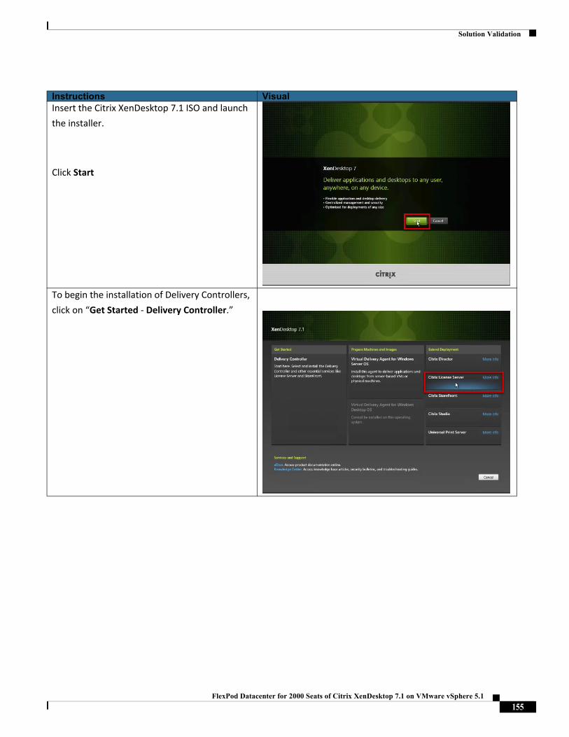
Solution Validation
Instructions VisualInsert the Citrix XenDesktop 7.1 ISO and launch
the installer.
Click Start
To begin the installation of Delivery Controllers,
click on “Get Started ‐ Delivery Controller.”
155FlexPod Datacenter for 2000 Seats of Citrix XenDesktop 7.1 on VMware vSphere 5.1
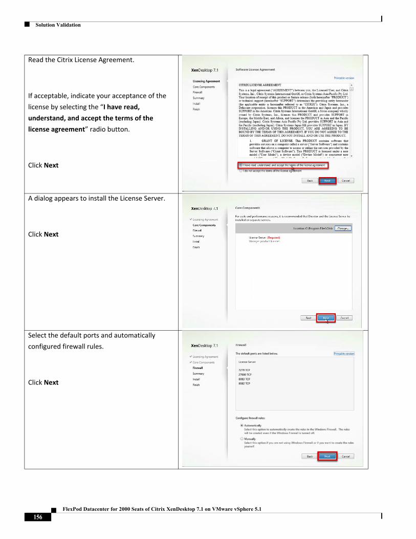
Solution Validation
Read the Citrix License Agreement.
If acceptable, indicate your acceptance of the
license by selecting the “I have read,
understand, and accept the terms of the
license agreement” radio button.
Click Next
A dialog appears to install the License Server.
Click Next
Select the default ports and automatically
configured firewall rules.
Click Next
156FlexPod Datacenter for 2000 Seats of Citrix XenDesktop 7.1 on VMware vSphere 5.1
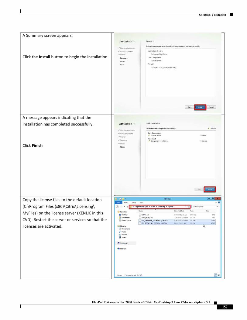
Solution Validation
A Summary screen appears.
Click the Install button to begin the installation.
A message appears indicating that the
installation has completed successfully.
Click Finish
Copy the license files to the default location
(C:\Program Files (x86)\Citrix\Licensing\
MyFiles) on the license server (XENLIC in this
CVD). Restart the server or services so that the
licenses are activated.
157FlexPod Datacenter for 2000 Seats of Citrix XenDesktop 7.1 on VMware vSphere 5.1
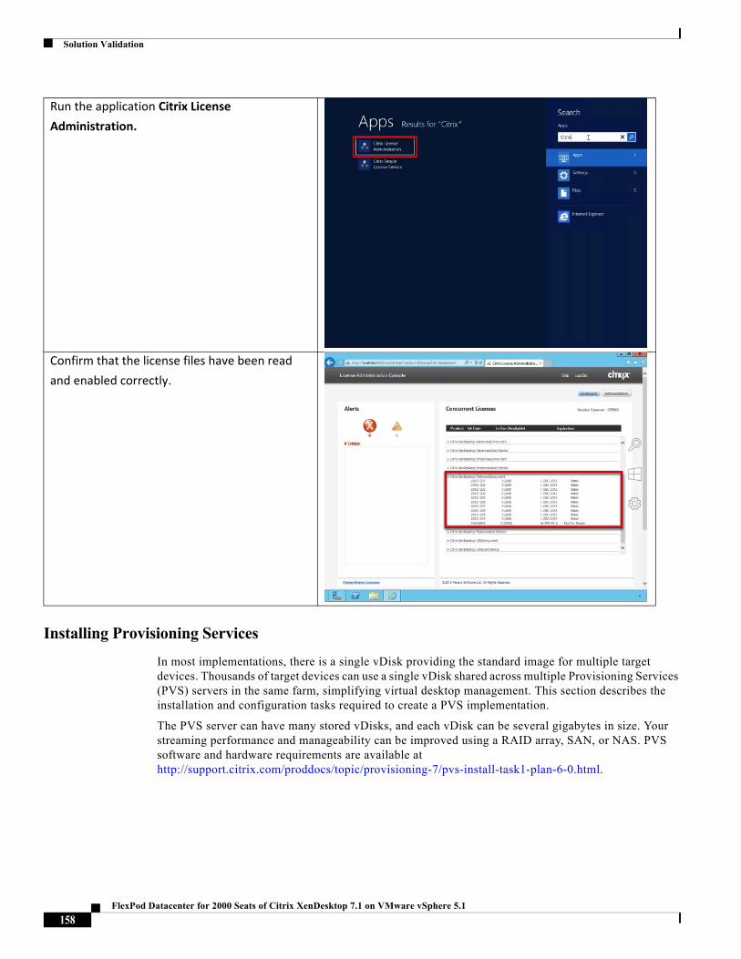
Solution Validation
Installing Provisioning Services
In most implementations, there is a single vDisk providing the standard image for multiple target devices. Thousands of target devices can use a single vDisk shared across multiple Provisioning Services (PVS) servers in the same farm, simplifying virtual desktop management. This section describes the installation and configuration tasks required to create a PVS implementation.
The PVS server can have many stored vDisks, and each vDisk can be several gigabytes in size. Your streaming performance and manageability can be improved using a RAID array, SAN, or NAS. PVS software and hardware requirements are available at http://support.citrix.com/proddocs/topic/provisioning-7/pvs-install-task1-plan-6-0.html.
Run the application Citrix License
Administration.
Confirm that the license files have been read
and enabled correctly.
158FlexPod Datacenter for 2000 Seats of Citrix XenDesktop 7.1 on VMware vSphere 5.1
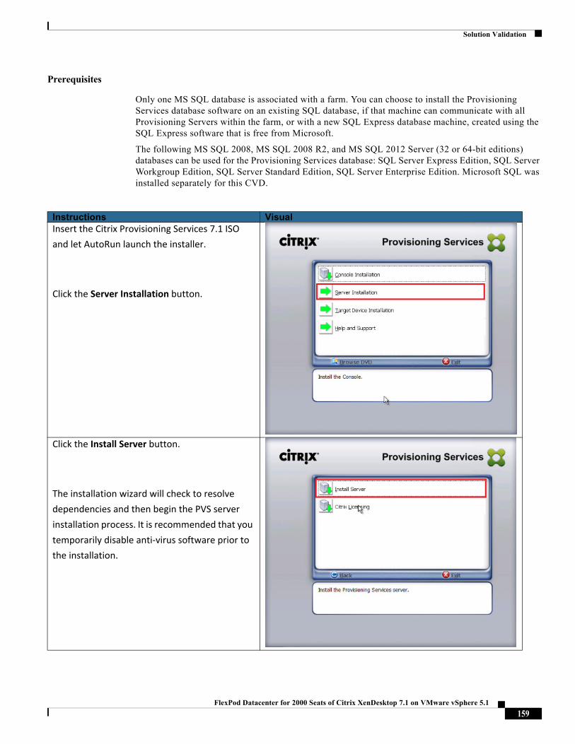
Solution Validation
Prerequisites
Only one MS SQL database is associated with a farm. You can choose to install the Provisioning Services database software on an existing SQL database, if that machine can communicate with all Provisioning Servers within the farm, or with a new SQL Express database machine, created using the SQL Express software that is free from Microsoft.
The following MS SQL 2008, MS SQL 2008 R2, and MS SQL 2012 Server (32 or 64-bit editions) databases can be used for the Provisioning Services database: SQL Server Express Edition, SQL Server Workgroup Edition, SQL Server Standard Edition, SQL Server Enterprise Edition. Microsoft SQL was installed separately for this CVD.
Instructions VisualInsert the Citrix Provisioning Services 7.1 ISO
and let AutoRun launch the installer.
Click the Server Installation button.
Click the Install Server button.
The installation wizard will check to resolve
dependencies and then begin the PVS server
installation process. It is recommended that you
temporarily disable anti‐virus software prior to
the installation.
159FlexPod Datacenter for 2000 Seats of Citrix XenDesktop 7.1 on VMware vSphere 5.1
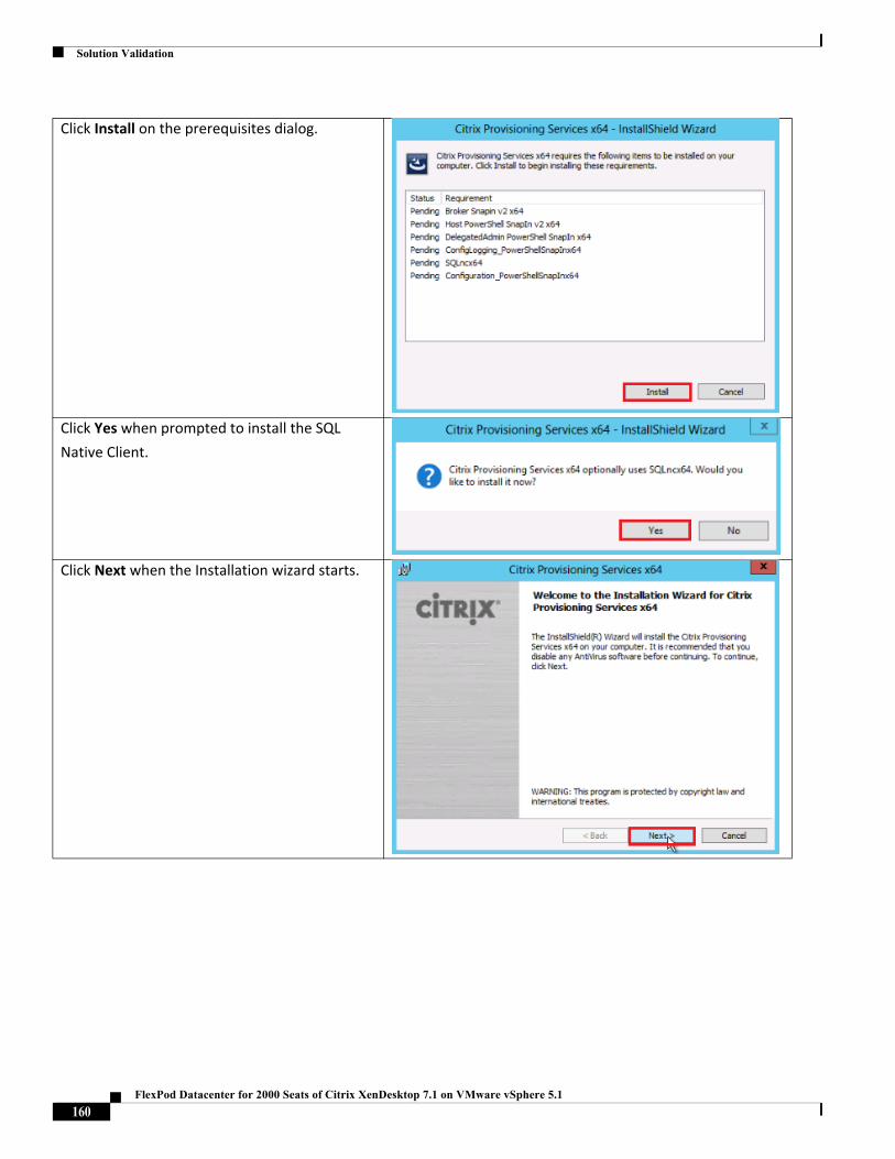
Solution Validation
Click Install on the prerequisites dialog.
Click Yes when prompted to install the SQL
Native Client.
Click Next when the Installation wizard starts.
160FlexPod Datacenter for 2000 Seats of Citrix XenDesktop 7.1 on VMware vSphere 5.1
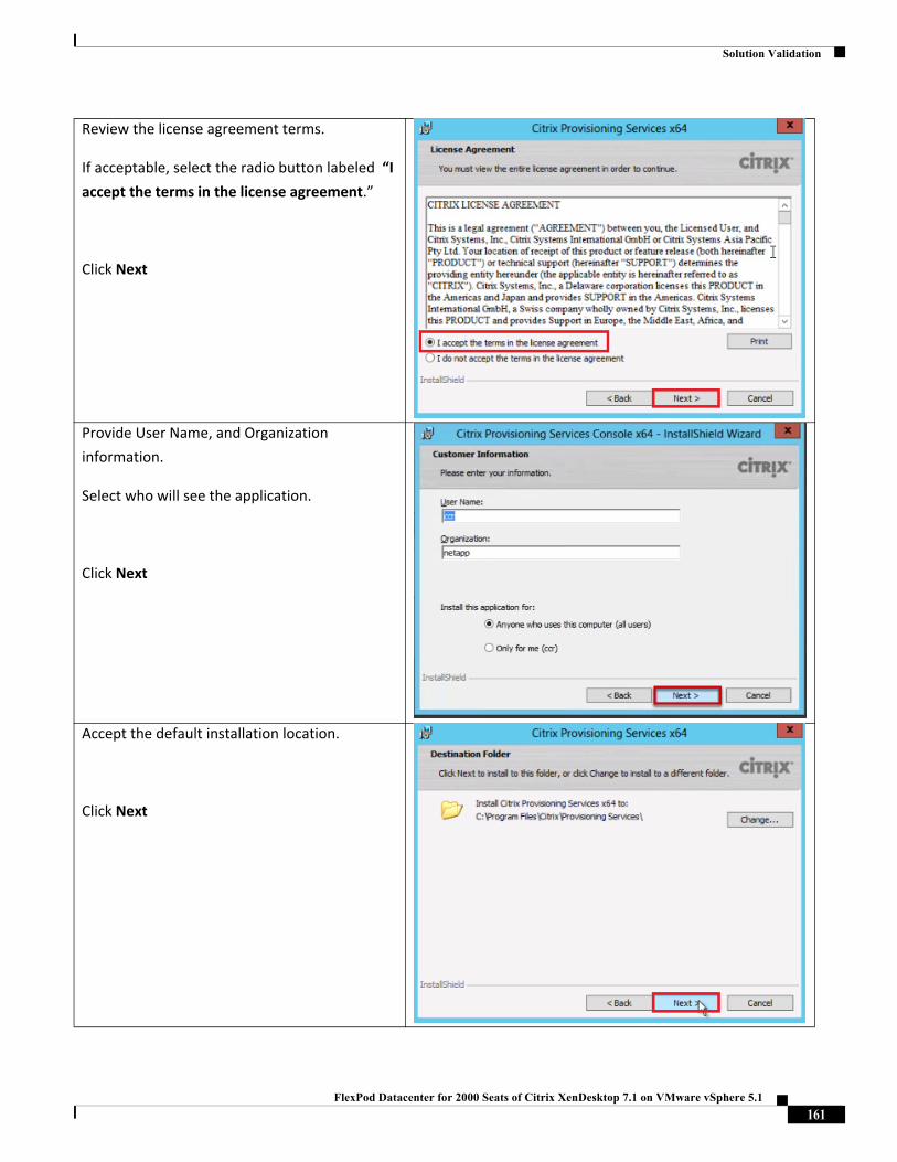
Solution Validation
Review the license agreement terms.
If acceptable, select the radio button labeled “I
accept the terms in the license agreement.”
Click Next
Provide User Name, and Organization
information.
Select who will see the application.
Click Next
Accept the default installation location.
Click Next
161FlexPod Datacenter for 2000 Seats of Citrix XenDesktop 7.1 on VMware vSphere 5.1
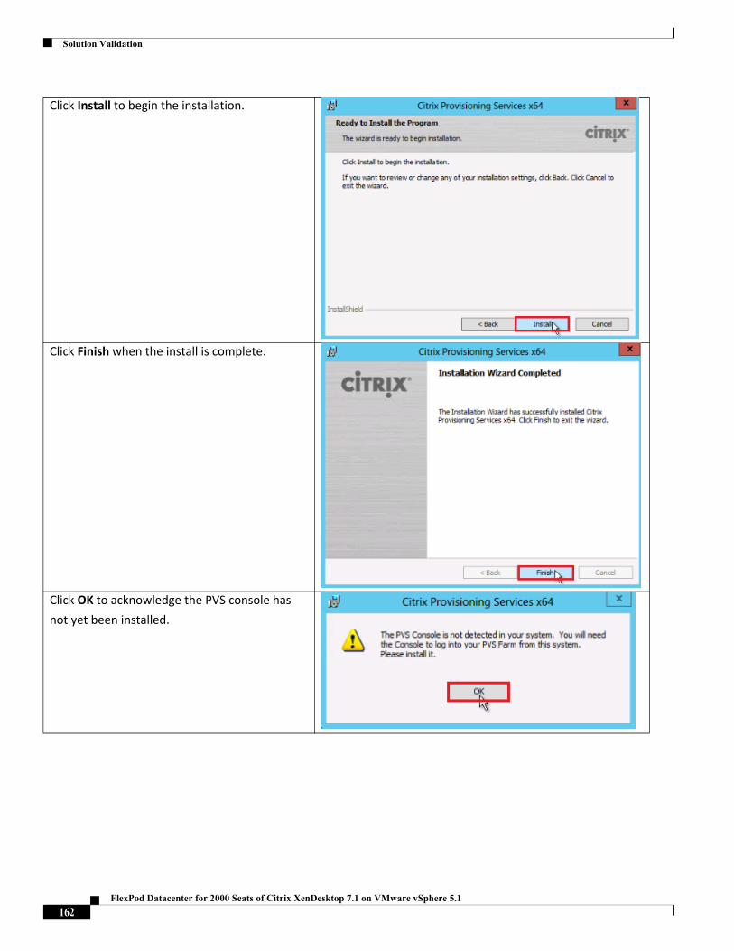
Solution Validation
Click Install to begin the installation.
Click Finish when the install is complete.
Click OK to acknowledge the PVS console has
not yet been installed.
162FlexPod Datacenter for 2000 Seats of Citrix XenDesktop 7.1 on VMware vSphere 5.1
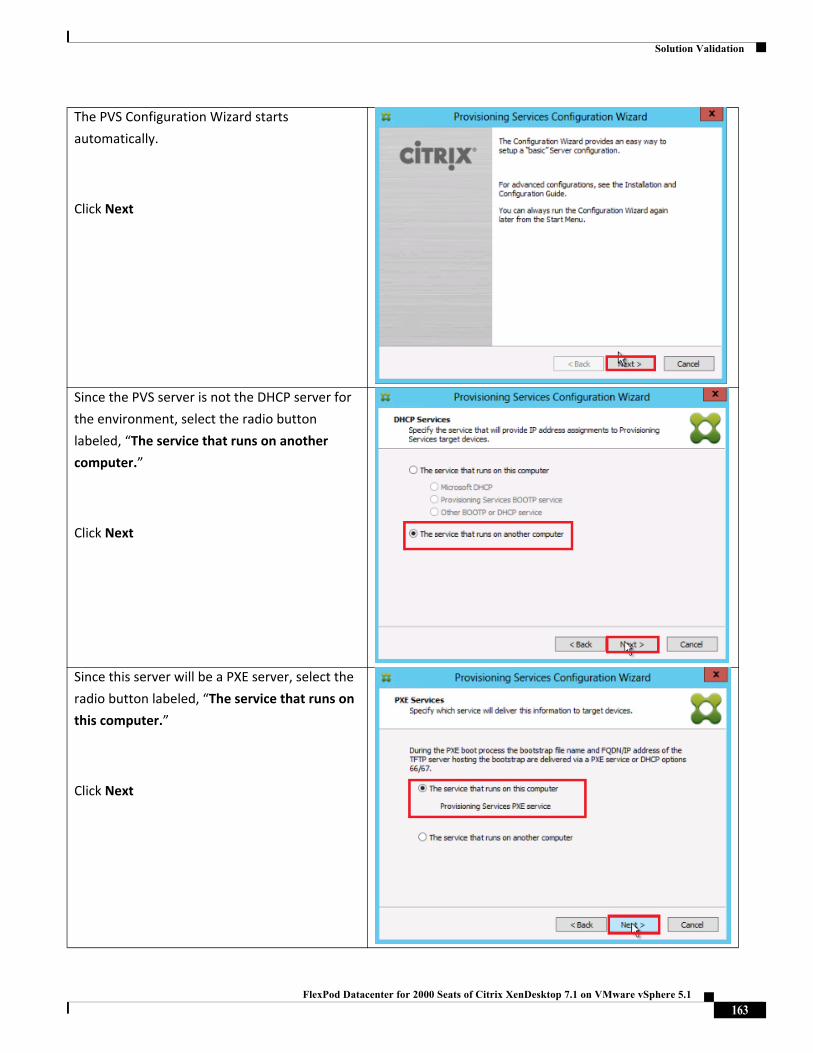
Solution Validation
The PVS Configuration Wizard starts
automatically.
Click Next
Since the PVS server is not the DHCP server for
the environment, select the radio button
labeled, “The service that runs on another
computer.”
Click Next
Since this server will be a PXE server, select the
radio button labeled, “The service that runs on
this computer.”
Click Next
163FlexPod Datacenter for 2000 Seats of Citrix XenDesktop 7.1 on VMware vSphere 5.1
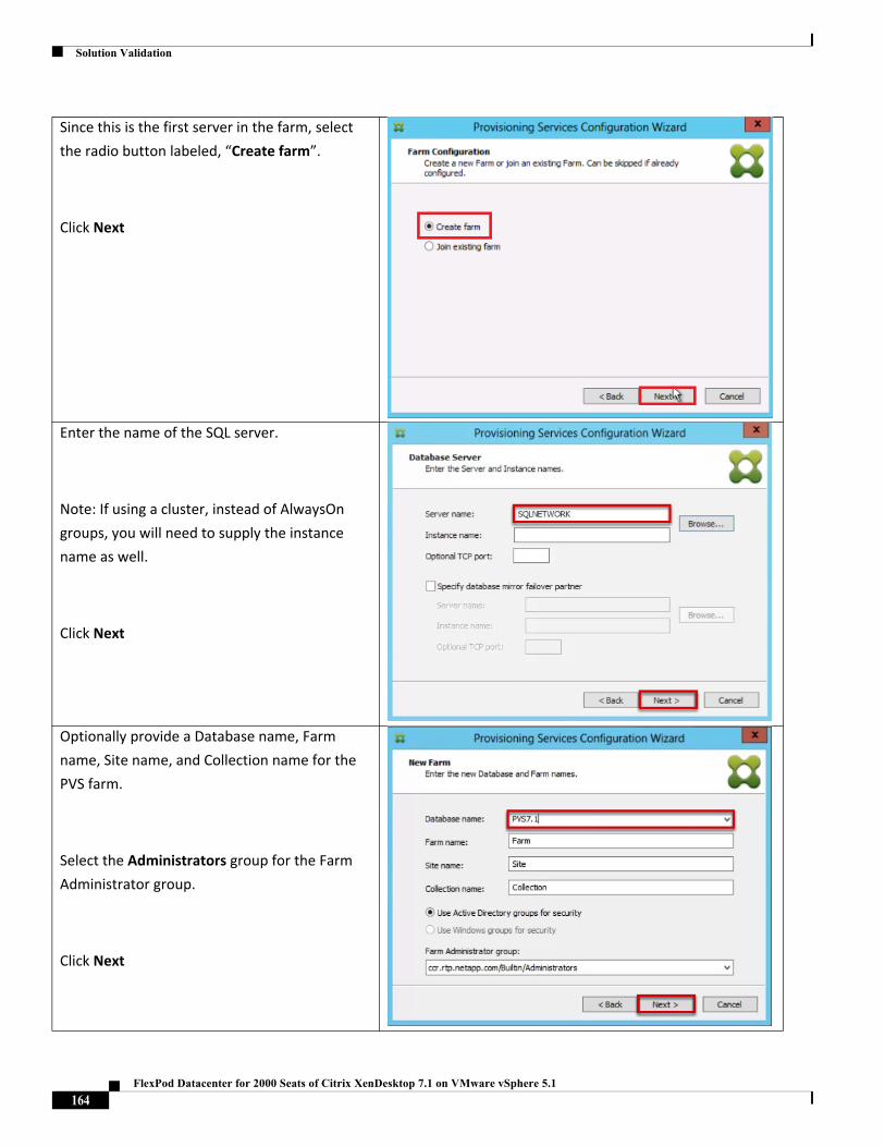
Solution Validation
Since this is the first server in the farm, select
the radio button labeled, “Create farm”.
Click Next
Enter the name of the SQL server.
Note: If using a cluster, instead of AlwaysOn
groups, you will need to supply the instance
name as well.
Click Next
Optionally provide a Database name, Farm
name, Site name, and Collection name for the
PVS farm.
Select the Administrators group for the Farm
Administrator group.
Click Next
164FlexPod Datacenter for 2000 Seats of Citrix XenDesktop 7.1 on VMware vSphere 5.1
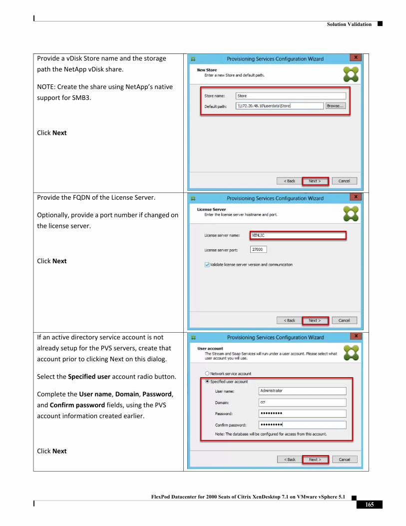
Solution Validation
Provide a vDisk Store name and the storage
path the NetApp vDisk share.
NOTE: Create the share using NetApp’s native
support for SMB3.
Click Next
Provide the FQDN of the License Server.
Optionally, provide a port number if changed on
the license server.
Click Next
If an active directory service account is not
already setup for the PVS servers, create that
account prior to clicking Next on this dialog.
Select the Specified user account radio button.
Complete the User name, Domain, Password,
and Confirm password fields, using the PVS
account information created earlier.
Click Next
165FlexPod Datacenter for 2000 Seats of Citrix XenDesktop 7.1 on VMware vSphere 5.1
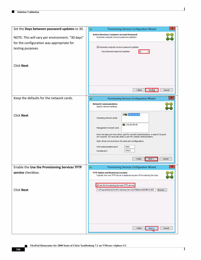
Solution Validation
Set the Days between password updates to 30.
NOTE: This will vary per environment. “30 days”
for the configuration was appropriate for
testing purposes.
Click Next
Keep the defaults for the network cards.
Click Next
Enable the Use the Provisioning Services TFTP
service checkbox.
Click Next
166FlexPod Datacenter for 2000 Seats of Citrix XenDesktop 7.1 on VMware vSphere 5.1
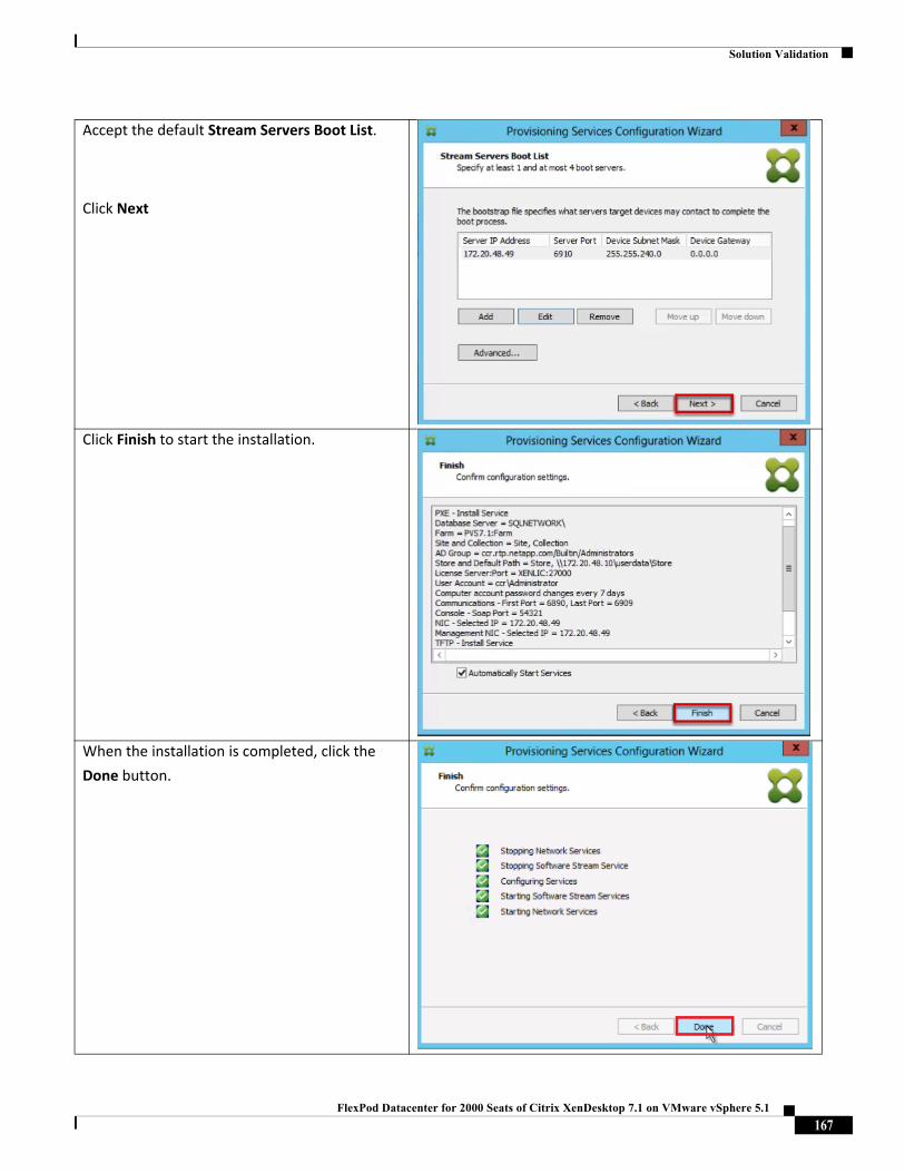
Solution Validation
Accept the default Stream Servers Boot List.
Click Next
Click Finish to start the installation.
When the installation is completed, click the
Done button.
167FlexPod Datacenter for 2000 Seats of Citrix XenDesktop 7.1 on VMware vSphere 5.1
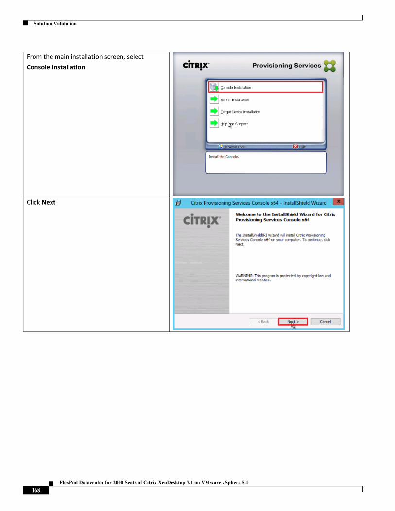
Solution Validation
From the main installation screen, select
Console Installation.
Click Next
168FlexPod Datacenter for 2000 Seats of Citrix XenDesktop 7.1 on VMware vSphere 5.1
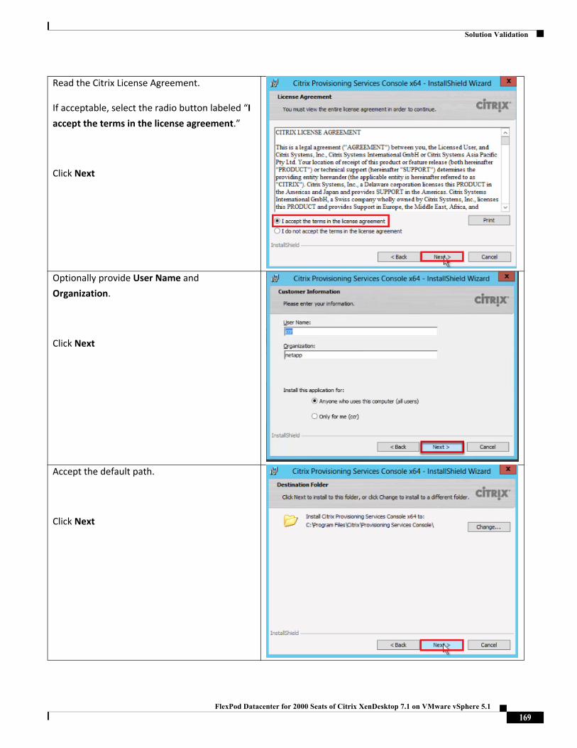
Solution Validation
Read the Citrix License Agreement.
If acceptable, select the radio button labeled “I
accept the terms in the license agreement.”
Click Next
Optionally provide User Name and
Organization.
Click Next
Accept the default path.
Click Next
169FlexPod Datacenter for 2000 Seats of Citrix XenDesktop 7.1 on VMware vSphere 5.1
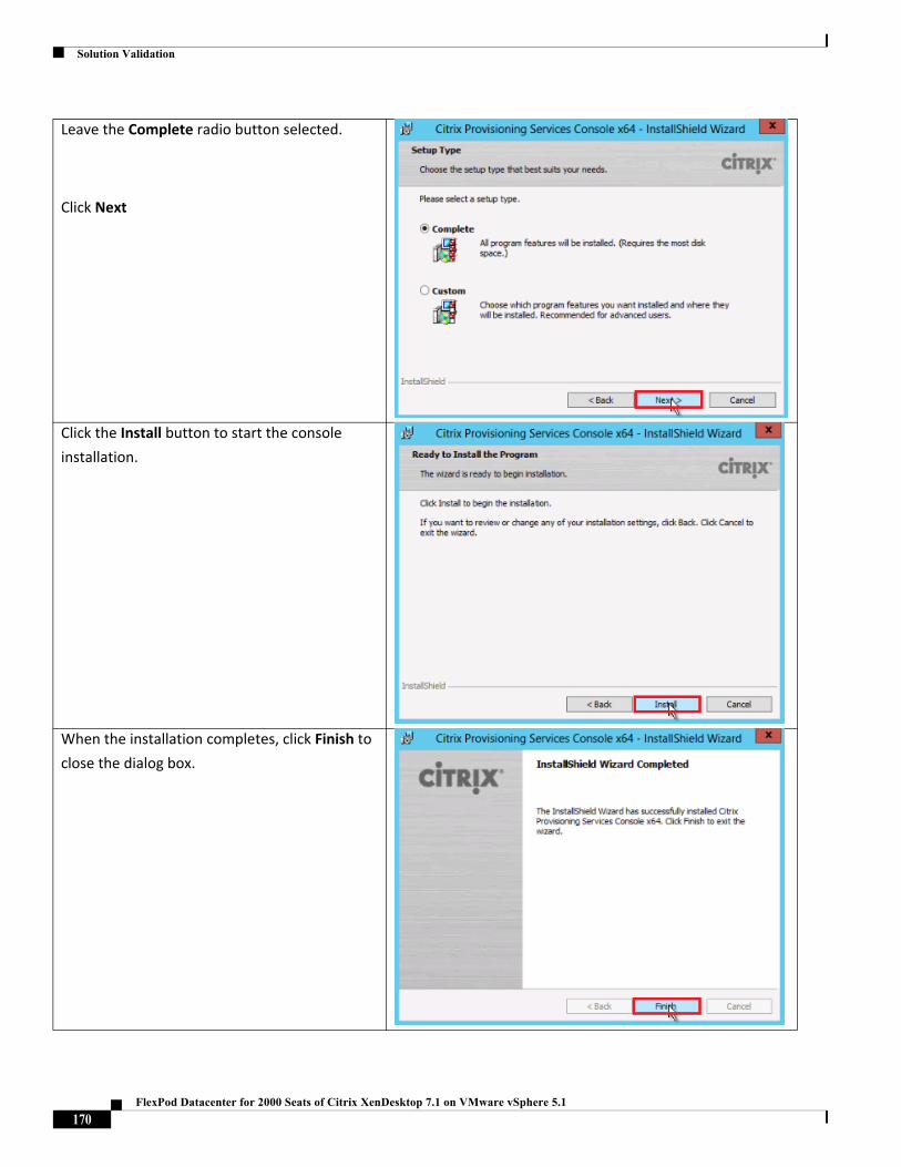
Solution Validation
Leave the Complete radio button selected.
Click Next
Click the Install button to start the console
installation.
When the installation completes, click Finish to
close the dialog box.
170FlexPod Datacenter for 2000 Seats of Citrix XenDesktop 7.1 on VMware vSphere 5.1
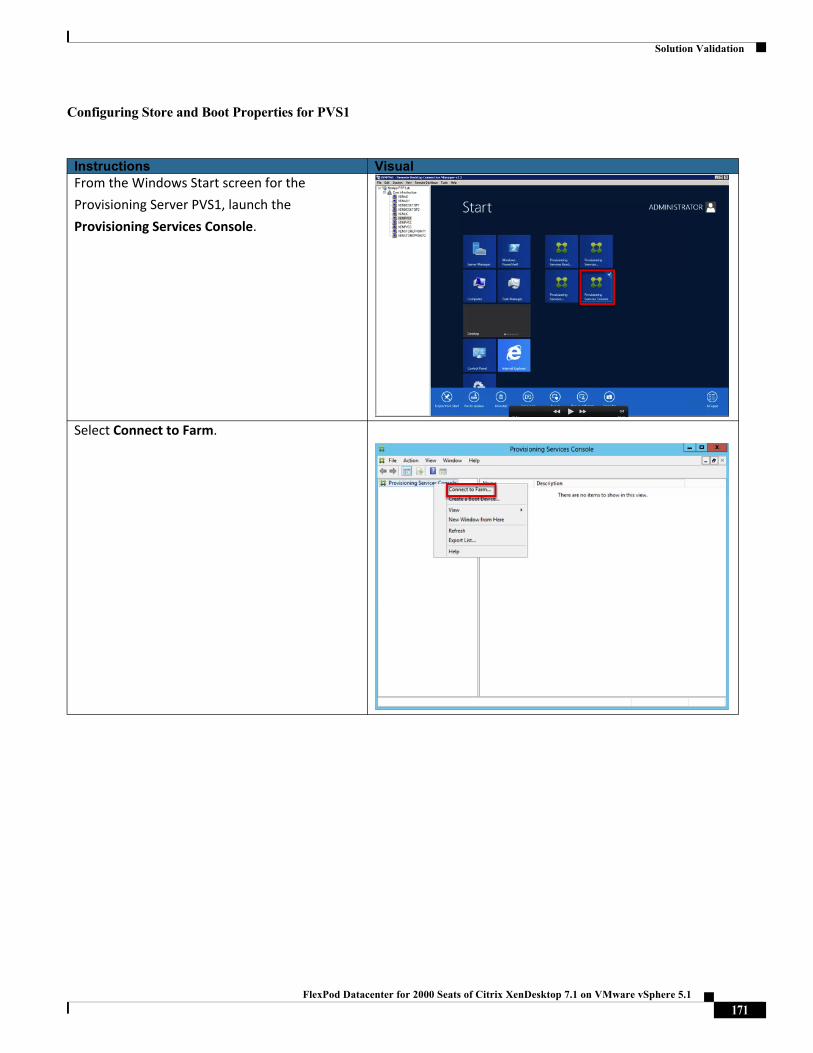
Solution Validation
Configuring Store and Boot Properties for PVS1
Instructions VisualFrom the Windows Start screen for the
Provisioning Server PVS1, launch the
Provisioning Services Console.
Select Connect to Farm.
171FlexPod Datacenter for 2000 Seats of Citrix XenDesktop 7.1 on VMware vSphere 5.1
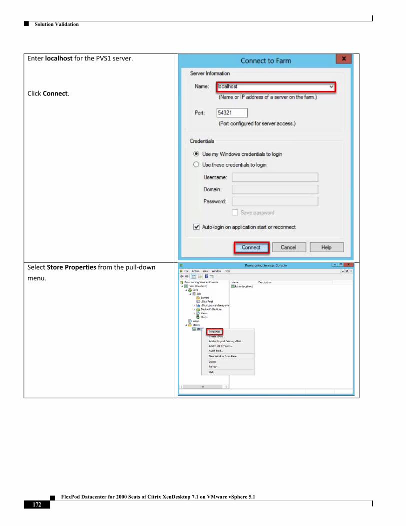
Solution Validation
Enter localhost for the PVS1 server.
Click Connect.
Select Store Properties from the pull‐down
menu.
172FlexPod Datacenter for 2000 Seats of Citrix XenDesktop 7.1 on VMware vSphere 5.1
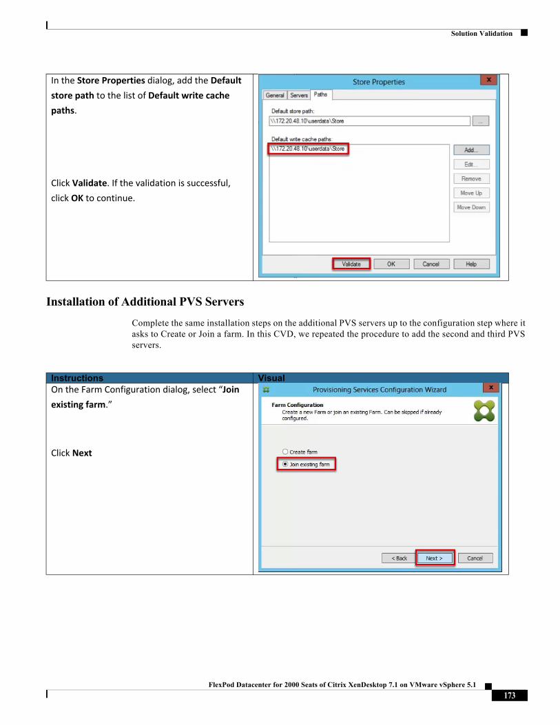
Solution Validation
Installation of Additional PVS Servers
Complete the same installation steps on the additional PVS servers up to the configuration step where it asks to Create or Join a farm. In this CVD, we repeated the procedure to add the second and third PVS servers.
In the Store Properties dialog, add the Default
store path to the list of Default write cache
paths.
Click Validate. If the validation is successful,
click OK to continue.
Instructions VisualOn the Farm Configuration dialog, select “Join
existing farm.”
Click Next
173FlexPod Datacenter for 2000 Seats of Citrix XenDesktop 7.1 on VMware vSphere 5.1
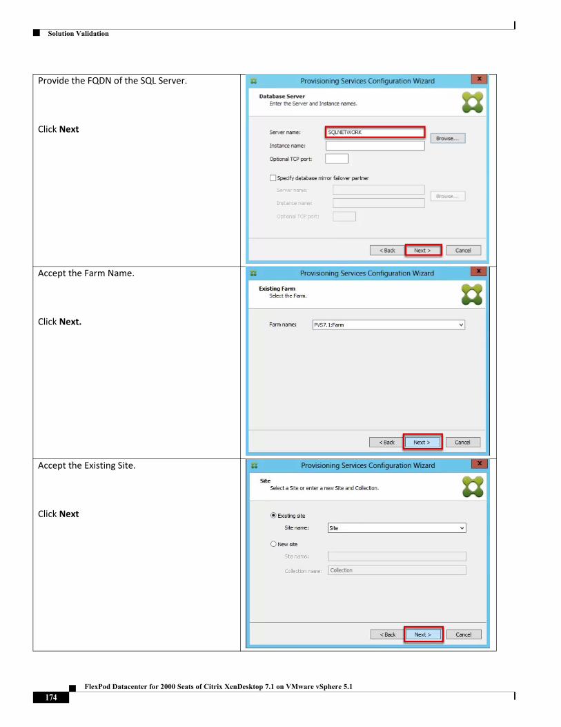
Solution Validation
Provide the FQDN of the SQL Server.
Click Next
Accept the Farm Name.
Click Next.
Accept the Existing Site.
Click Next
174FlexPod Datacenter for 2000 Seats of Citrix XenDesktop 7.1 on VMware vSphere 5.1
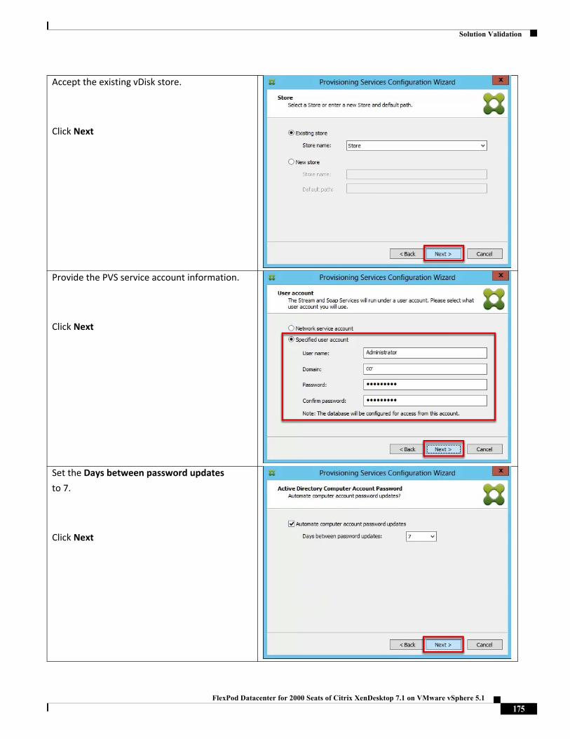
Solution Validation
Accept the existing vDisk store.
Click Next
Provide the PVS service account information.
Click Next
Set the Days between password updates to 7.
Click Next
175FlexPod Datacenter for 2000 Seats of Citrix XenDesktop 7.1 on VMware vSphere 5.1
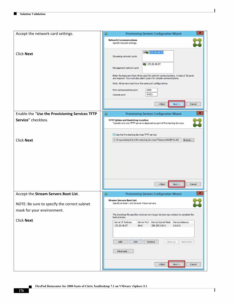
Solution Validation
Accept the network card settings.
Click Next
Enable the “Use the Provisioning Services TFTP
Service” checkbox.
Click Next
Accept the Stream Servers Boot List.
NOTE: Be sure to specify the correct subnet
mask for your environment.
Click Next
176FlexPod Datacenter for 2000 Seats of Citrix XenDesktop 7.1 on VMware vSphere 5.1
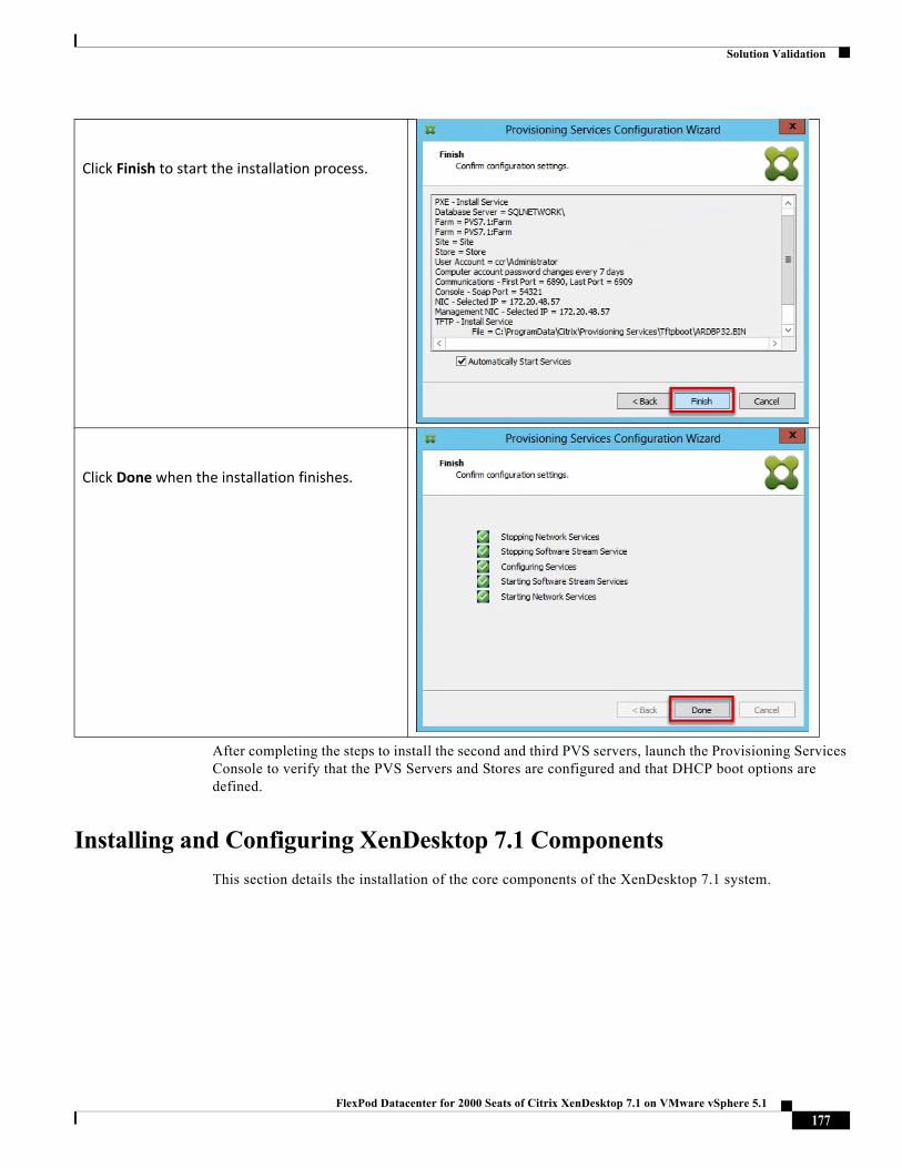
Solution Validation
After completing the steps to install the second and third PVS servers, launch the Provisioning Services Console to verify that the PVS Servers and Stores are configured and that DHCP boot options are defined.
Installing and Configuring XenDesktop 7.1 Components
This section details the installation of the core components of the XenDesktop 7.1 system.
Click Finish to start the installation process.
Click Done when the installation finishes.
177FlexPod Datacenter for 2000 Seats of Citrix XenDesktop 7.1 on VMware vSphere 5.1
Solution Validation
Installing the XenDesktop Delivery Controllers
This CVD installs two XenDesktop Delivery Controllers to support both hosted shared desktops (RDS) and pooled virtual desktops (VDI).
Installing the XenDesktop Delivery Controller and Other Software Components
The process of installing the XenDesktop Delivery Controller also installs other key XenDesktop software components, including Studio, which is used to create and manage infrastructure components, and Director, which is used to monitor performance and troubleshoot problems.
Instructions Visual
178FlexPod Datacenter for 2000 Seats of Citrix XenDesktop 7.1 on VMware vSphere 5.1
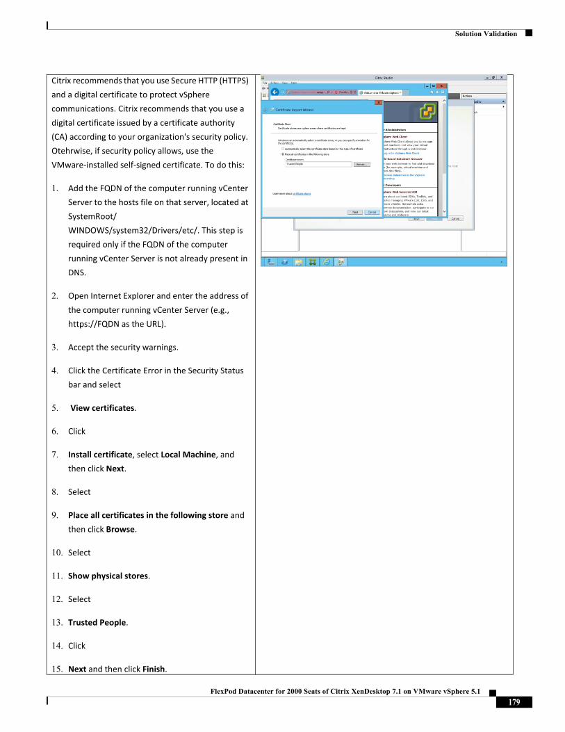
Solution Validation
Citrix recommends that you use Secure HTTP (HTTPS)
and a digital certificate to protect vSphere
communications. Citrix recommends that you use a
digital certificate issued by a certificate authority
(CA) according to your organization's security policy.
Otehrwise, if security policy allows, use the
VMware‐installed self‐signed certificate. To do this:
1. Add the FQDN of the computer running vCenter
Server to the hosts file on that server, located at
SystemRoot/WINDOWS/system32/Drivers/etc/. This step is
required only if the FQDN of the computer
running vCenter Server is not already present in
DNS.
2. Open Internet Explorer and enter the address of
the computer running vCenter Server (e.g.,
https://FQDN as the URL).
3. Accept the security warnings.
4. Click the Certificate Error in the Security Status
bar and select
5. View certificates.
6. Click
7. Install certificate, select Local Machine, and
then click Next.
8. Select
9. Place all certificates in the following store and
then click Browse.
10. Select
11. Show physical stores.
12. Select
13. Trusted People.
14. Click
15. Next and then click Finish.
179FlexPod Datacenter for 2000 Seats of Citrix XenDesktop 7.1 on VMware vSphere 5.1
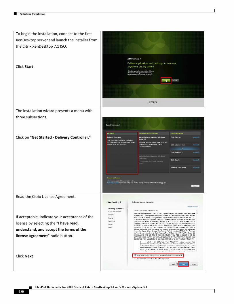
Solution Validation
To begin the installation, connect to the first
XenDesktop server and launch the installer from
the Citrix XenDesktop 7.1 ISO.
Click Start
The installation wizard presents a menu with
three subsections.
Click on “Get Started ‐ Delivery Controller.”
Read the Citrix License Agreement.
If acceptable, indicate your acceptance of the
license by selecting the “I have read,
understand, and accept the terms of the
license agreement” radio button.
Click Next
180FlexPod Datacenter for 2000 Seats of Citrix XenDesktop 7.1 on VMware vSphere 5.1
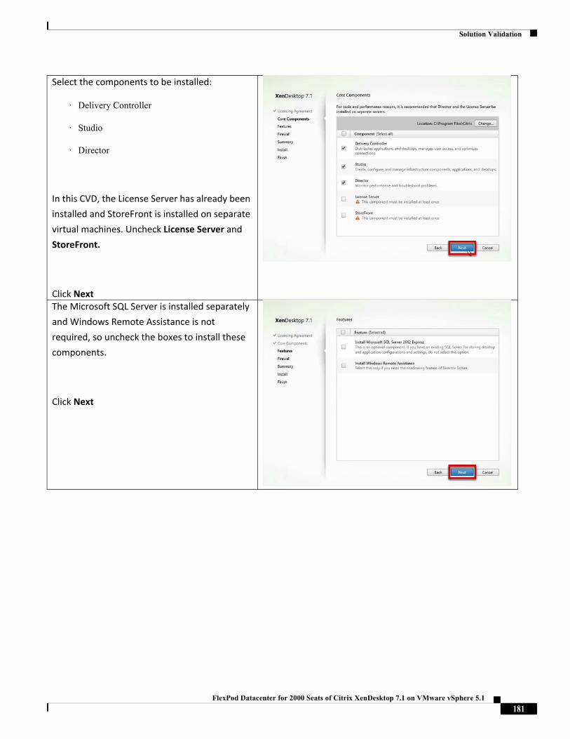
Solution Validation
Select the components to be installed:
· Delivery Controller
· Studio
· Director
In this CVD, the License Server has already been
installed and StoreFront is installed on separate
virtual machines. Uncheck License Server and
StoreFront.
Click NextThe Microsoft SQL Server is installed separately
and Windows Remote Assistance is not
required, so uncheck the boxes to install these
components.
Click Next
181FlexPod Datacenter for 2000 Seats of Citrix XenDesktop 7.1 on VMware vSphere 5.1
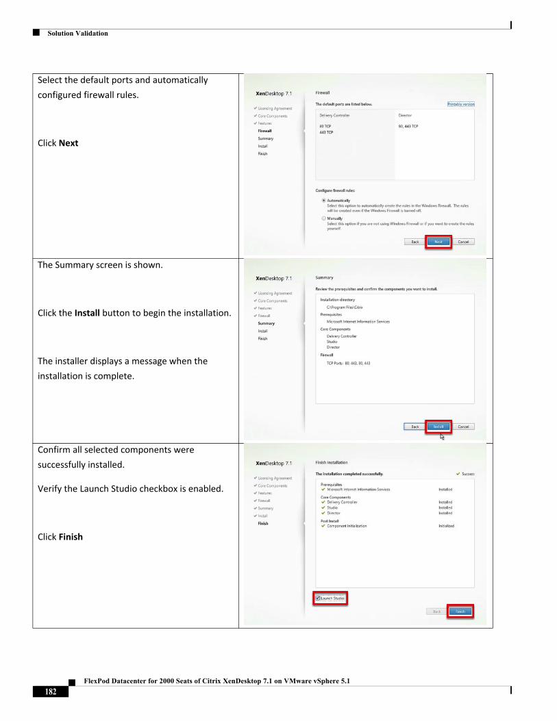
Solution Validation
Select the default ports and automatically
configured firewall rules.
Click Next
The Summary screen is shown.
Click the Install button to begin the installation.
The installer displays a message when the
installation is complete.
Confirm all selected components were
successfully installed.
Verify the Launch Studio checkbox is enabled.
Click Finish
182FlexPod Datacenter for 2000 Seats of Citrix XenDesktop 7.1 on VMware vSphere 5.1
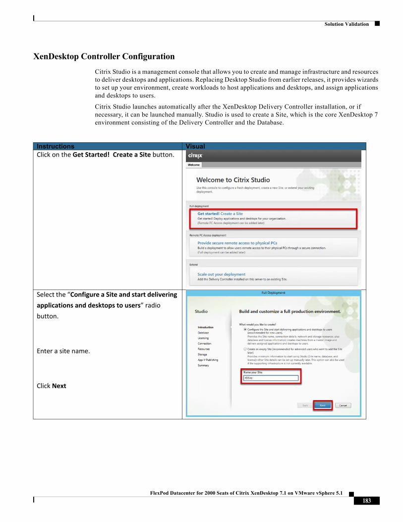
Solution Validation
XenDesktop Controller Configuration
Citrix Studio is a management console that allows you to create and manage infrastructure and resources to deliver desktops and applications. Replacing Desktop Studio from earlier releases, it provides wizards to set up your environment, create workloads to host applications and desktops, and assign applications and desktops to users.
Citrix Studio launches automatically after the XenDesktop Delivery Controller installation, or if necessary, it can be launched manually. Studio is used to create a Site, which is the core XenDesktop 7 environment consisting of the Delivery Controller and the Database.
Instructions VisualClick on the Get Started! Create a Site button.
Select the “Configure a Site and start delivering
applications and desktops to users” radio
button.
Enter a site name.
Click Next
183FlexPod Datacenter for 2000 Seats of Citrix XenDesktop 7.1 on VMware vSphere 5.1
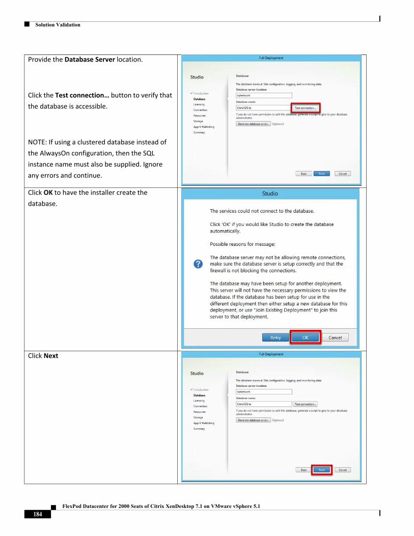
Solution Validation
Provide the Database Server location.
Click the Test connection… button to verify that
the database is accessible.
NOTE: If using a clustered database instead of
the AlwaysOn configuration, then the SQL
instance name must also be supplied. Ignore
any errors and continue.
Click OK to have the installer create the
database.
Click Next
184FlexPod Datacenter for 2000 Seats of Citrix XenDesktop 7.1 on VMware vSphere 5.1
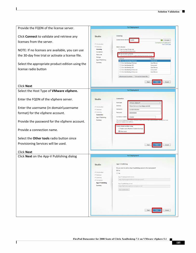
Solution Validation
Provide the FQDN of the license server.
Click Connect to validate and retrieve any
licenses from the server.
NOTE: If no licenses are available, you can use
the 30‐day free trial or activate a license file.
Select the appropriate product edition using the
license radio button
Click Next
Select the Host Type of VMware vSphere.
Enter the FQDN of the vSphere server.
Enter the username (in domain\username
format) for the vSphere account.
Provide the password for the vSphere account.
Provide a connection name.
Select the Other tools radio button since
Provisioning Services will be used.
Click NextClick Next on the App‐V Publishing dialog
185FlexPod Datacenter for 2000 Seats of Citrix XenDesktop 7.1 on VMware vSphere 5.1
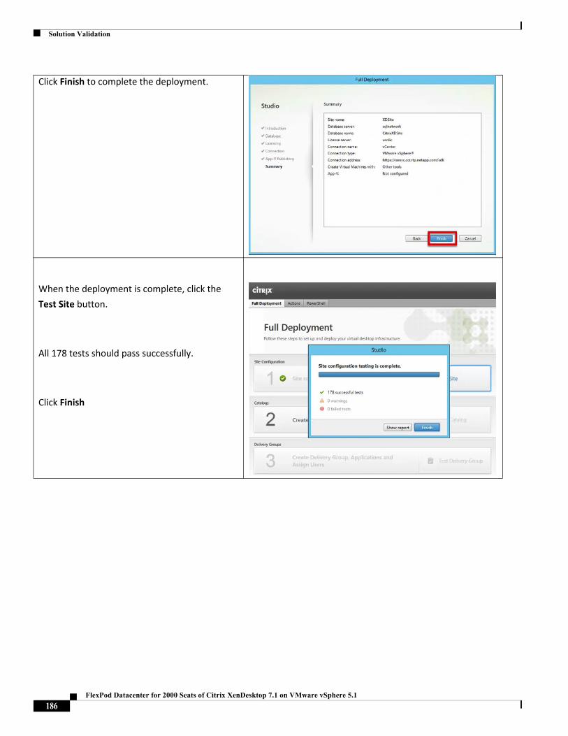
Solution Validation
Click Finish to complete the deployment.
When the deployment is complete, click the
Test Site button.
All 178 tests should pass successfully.
Click Finish
186FlexPod Datacenter for 2000 Seats of Citrix XenDesktop 7.1 on VMware vSphere 5.1
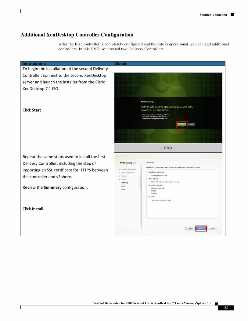
Solution Validation
Additional XenDesktop Controller Configuration
After the first controller is completely configured and the Site is operational, you can add additional controllers. In this CVD, we created two Delivery Controllers.
Instructions VisualTo begin the installation of the second Delivery
Controller, connect to the second XenDesktop
server and launch the installer from the Citrix
XenDesktop 7.1 ISO.
Click Start
Repeat the same steps used to install the first
Delivery Controller, including the step of
importing an SSL certificate for HTTPS between
the controller and vSphere.
Review the Summary configuration.
Click Install
187FlexPod Datacenter for 2000 Seats of Citrix XenDesktop 7.1 on VMware vSphere 5.1
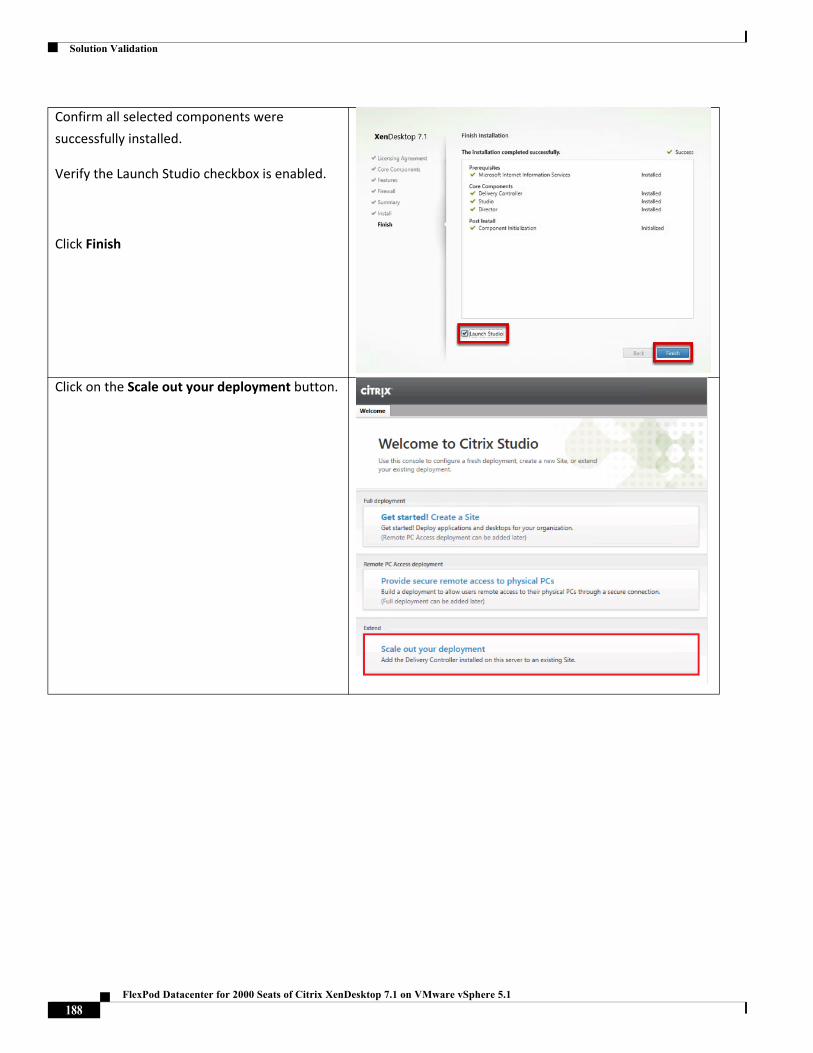
Solution Validation
Confirm all selected components were
successfully installed.
Verify the Launch Studio checkbox is enabled.
Click Finish
Click on the Scale out your deployment button.
188FlexPod Datacenter for 2000 Seats of Citrix XenDesktop 7.1 on VMware vSphere 5.1
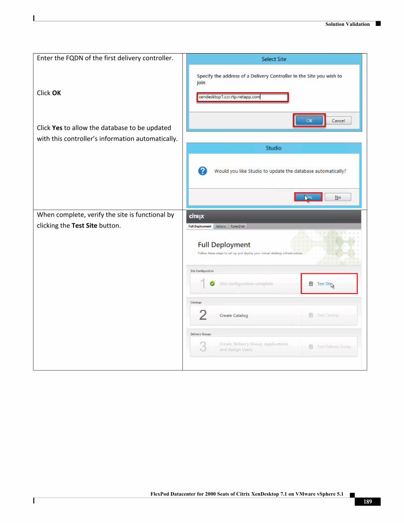
Solution Validation
Enter the FQDN of the first delivery controller.
Click OK
Click Yes to allow the database to be updated
with this controller’s information automatically.
When complete, verify the site is functional by
clicking the Test Site button.
189FlexPod Datacenter for 2000 Seats of Citrix XenDesktop 7.1 on VMware vSphere 5.1
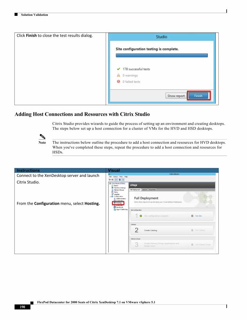
Solution Validation
Adding Host Connections and Resources with Citrix Studio
Citrix Studio provides wizards to guide the process of setting up an environment and creating desktops. The steps below set up a host connection for a cluster of VMs for the HVD and HSD desktops.
Note The instructions below outline the procedure to add a host connection and resources for HVD desktops. When you've completed these steps, repeat the procedure to add a host connection and resources for HSDs.
Click Finish to close the test results dialog.
Instructions VisualConnect to the XenDesktop server and launch
Citrix Studio.
From the Configuration menu, select Hosting.
190FlexPod Datacenter for 2000 Seats of Citrix XenDesktop 7.1 on VMware vSphere 5.1
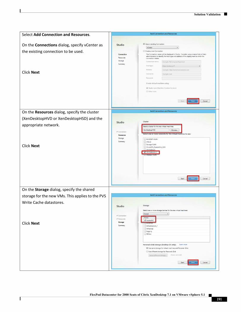
Solution Validation
Select Add Connection and Resources.
On the Connections dialog, specify vCenter as
the existing connection to be used.
Click Next
On the Resources dialog, specify the cluster
(XenDesktopHVD or XenDesktopHSD) and the
appropriate network.
Click Next
On the Storage dialog, specify the shared
storage for the new VMs. This applies to the PVS
Write Cache datastores.
Click Next
191FlexPod Datacenter for 2000 Seats of Citrix XenDesktop 7.1 on VMware vSphere 5.1
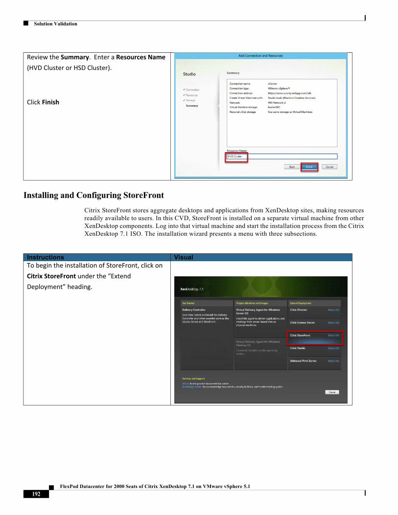
Solution Validation
Installing and Configuring StoreFront
Citrix StoreFront stores aggregate desktops and applications from XenDesktop sites, making resources readily available to users. In this CVD, StoreFront is installed on a separate virtual machine from other XenDesktop components. Log into that virtual machine and start the installation process from the Citrix XenDesktop 7.1 ISO. The installation wizard presents a menu with three subsections.
Review the Summary. Enter a Resources Name
(HVD Cluster or HSD Cluster).
Click Finish
Instructions VisualTo begin the installation of StoreFront, click on
Citrix StoreFront under the “Extend
Deployment” heading.
192FlexPod Datacenter for 2000 Seats of Citrix XenDesktop 7.1 on VMware vSphere 5.1
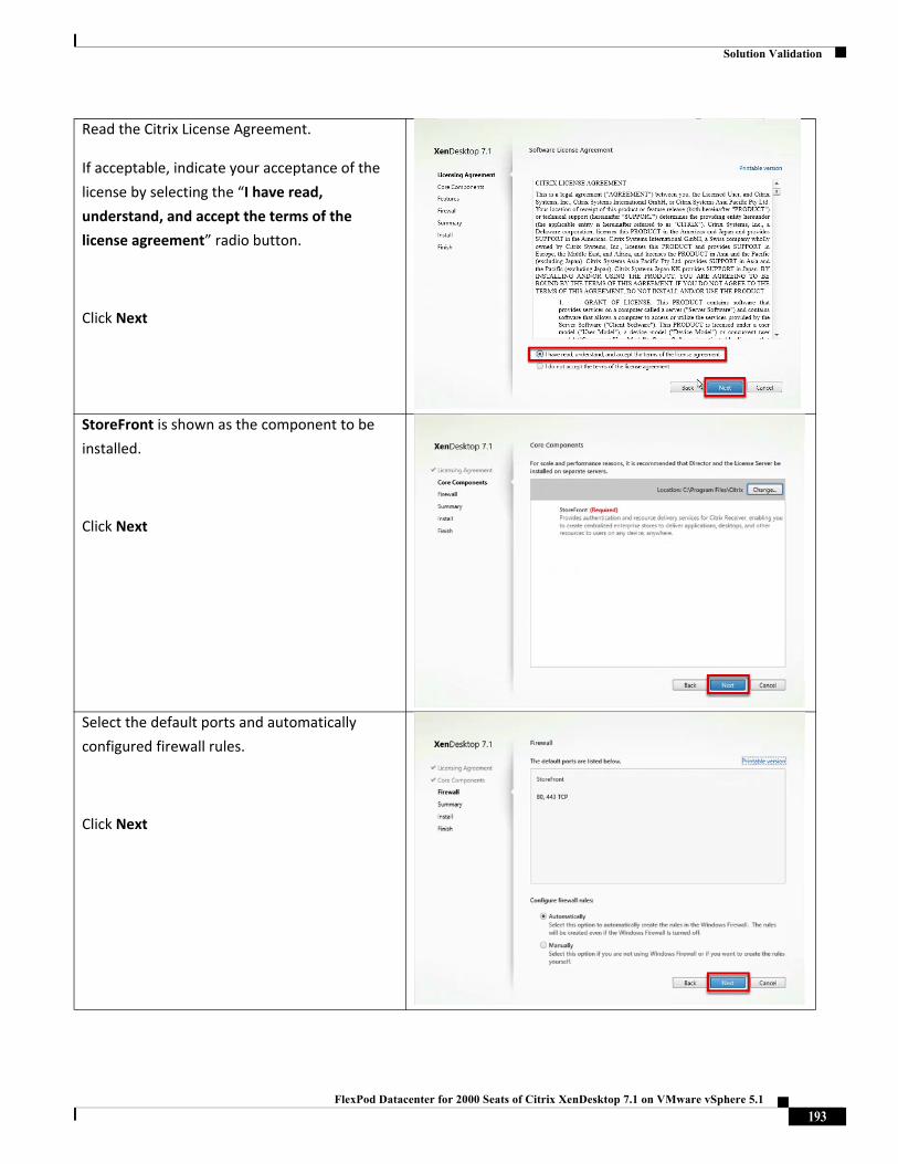
Solution Validation
Read the Citrix License Agreement.
If acceptable, indicate your acceptance of the
license by selecting the “I have read,
understand, and accept the terms of the
license agreement” radio button.
Click Next
StoreFront is shown as the component to be
installed.
Click Next
Select the default ports and automatically
configured firewall rules.
Click Next
193FlexPod Datacenter for 2000 Seats of Citrix XenDesktop 7.1 on VMware vSphere 5.1
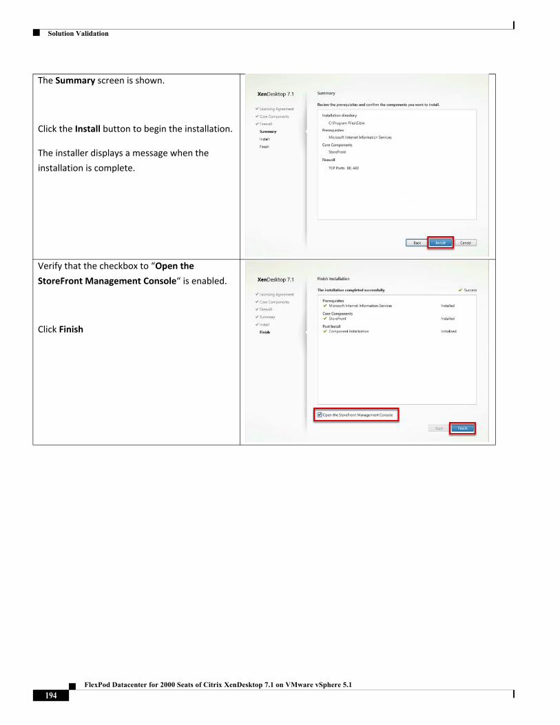
Solution Validation
The Summary screen is shown.
Click the Install button to begin the installation.
The installer displays a message when the
installation is complete.
Verify that the checkbox to “Open the
StoreFront Management Console“ is enabled.
Click Finish
194FlexPod Datacenter for 2000 Seats of Citrix XenDesktop 7.1 on VMware vSphere 5.1
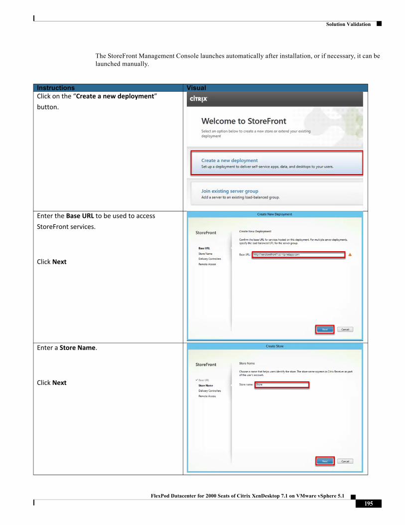
Solution Validation
The StoreFront Management Console launches automatically after installation, or if necessary, it can be launched manually.
Instructions VisualClick on the “Create a new deployment”
button.
Enter the Base URL to be used to access
StoreFront services.
Click Next
Enter a Store Name.
Click Next
195FlexPod Datacenter for 2000 Seats of Citrix XenDesktop 7.1 on VMware vSphere 5.1
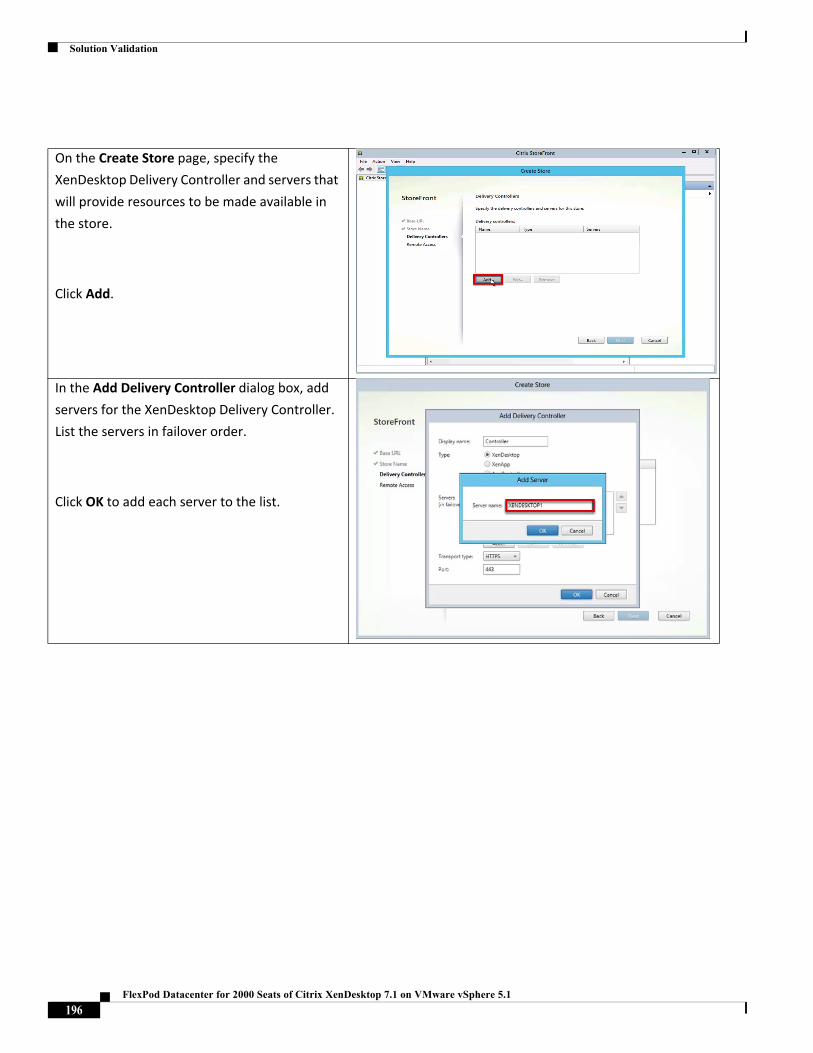
Solution Validation
On the Create Store page, specify the
XenDesktop Delivery Controller and servers that
will provide resources to be made available in
the store.
Click Add.
In the Add Delivery Controller dialog box, add
servers for the XenDesktop Delivery Controller.
List the servers in failover order.
Click OK to add each server to the list.
196FlexPod Datacenter for 2000 Seats of Citrix XenDesktop 7.1 on VMware vSphere 5.1
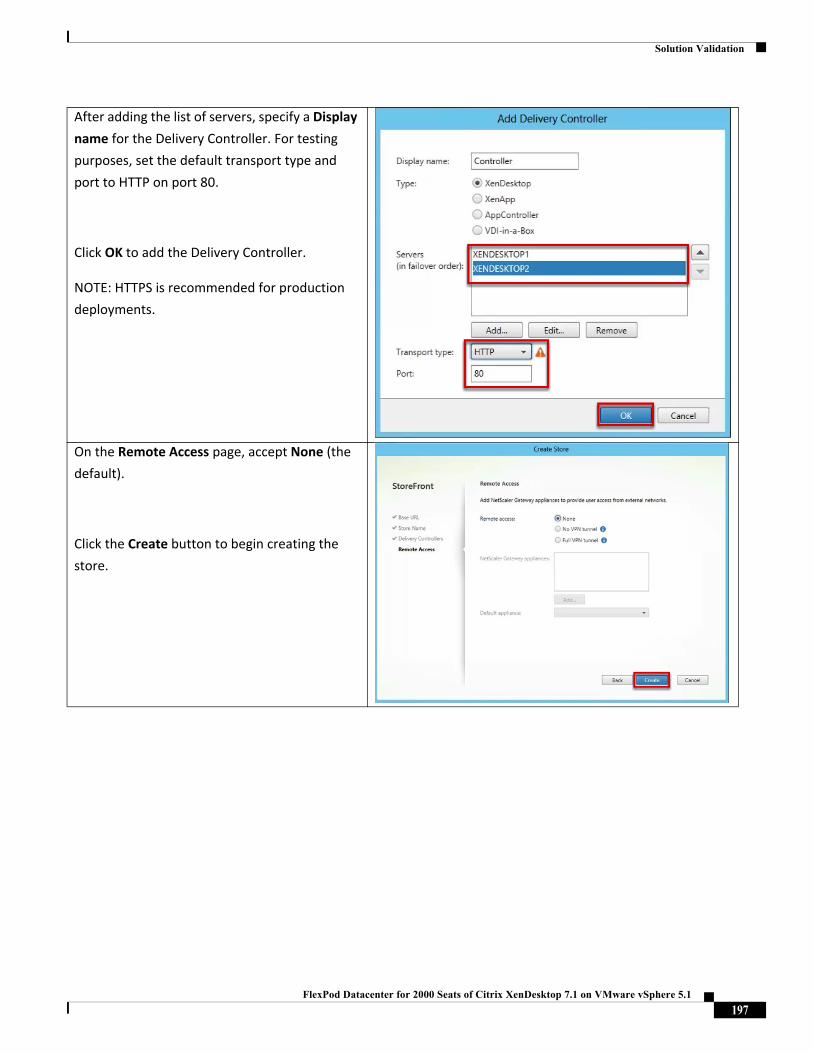
Solution Validation
After adding the list of servers, specify a Display
name for the Delivery Controller. For testing
purposes, set the default transport type and
port to HTTP on port 80.
Click OK to add the Delivery Controller.
NOTE: HTTPS is recommended for production
deployments.
On the Remote Access page, accept None (the
default).
Click the Create button to begin creating the
store.
197FlexPod Datacenter for 2000 Seats of Citrix XenDesktop 7.1 on VMware vSphere 5.1
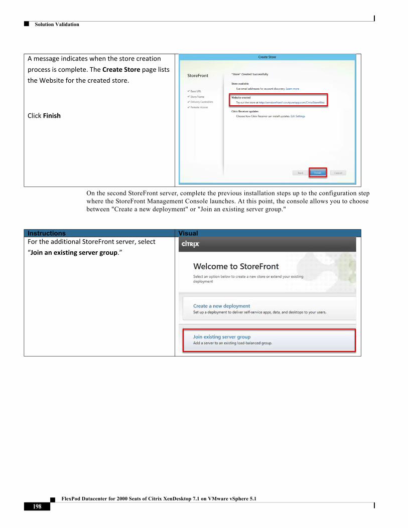
Solution Validation
On the second StoreFront server, complete the previous installation steps up to the configuration step where the StoreFront Management Console launches. At this point, the console allows you to choose between "Create a new deployment" or "Join an existing server group."
A message indicates when the store creation
process is complete. The Create Store page lists
the Website for the created store.
Click Finish
Instructions VisualFor the additional StoreFront server, select
“Join an existing server group.”
198FlexPod Datacenter for 2000 Seats of Citrix XenDesktop 7.1 on VMware vSphere 5.1
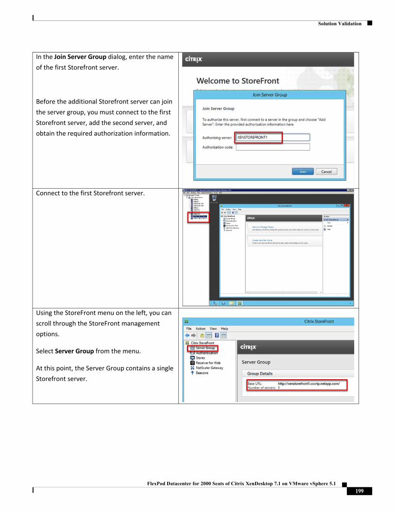
Solution Validation
In the Join Server Group dialog, enter the name
of the first Storefront server.
Before the additional Storefront server can join
the server group, you must connect to the first
Storefront server, add the second server, and
obtain the required authorization information.
Connect to the first Storefront server.
Using the StoreFront menu on the left, you can
scroll through the StoreFront management
options.
Select Server Group from the menu.
At this point, the Server Group contains a single
Storefront server.
199FlexPod Datacenter for 2000 Seats of Citrix XenDesktop 7.1 on VMware vSphere 5.1
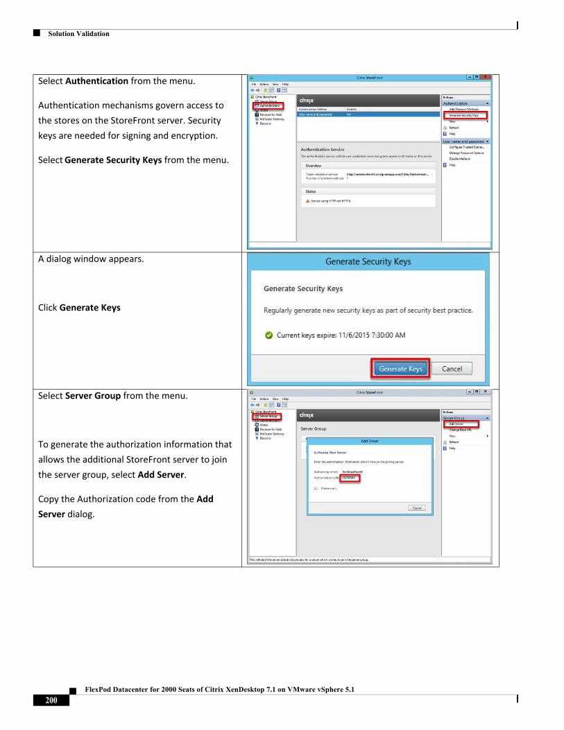
Solution Validation
Select Authentication from the menu.
Authentication mechanisms govern access to
the stores on the StoreFront server. Security
keys are needed for signing and encryption.
Select Generate Security Keys from the menu.
A dialog window appears.
Click Generate Keys
Select Server Group from the menu.
To generate the authorization information that
allows the additional StoreFront server to join
the server group, select Add Server.
Copy the Authorization code from the Add
Server dialog.
200FlexPod Datacenter for 2000 Seats of Citrix XenDesktop 7.1 on VMware vSphere 5.1
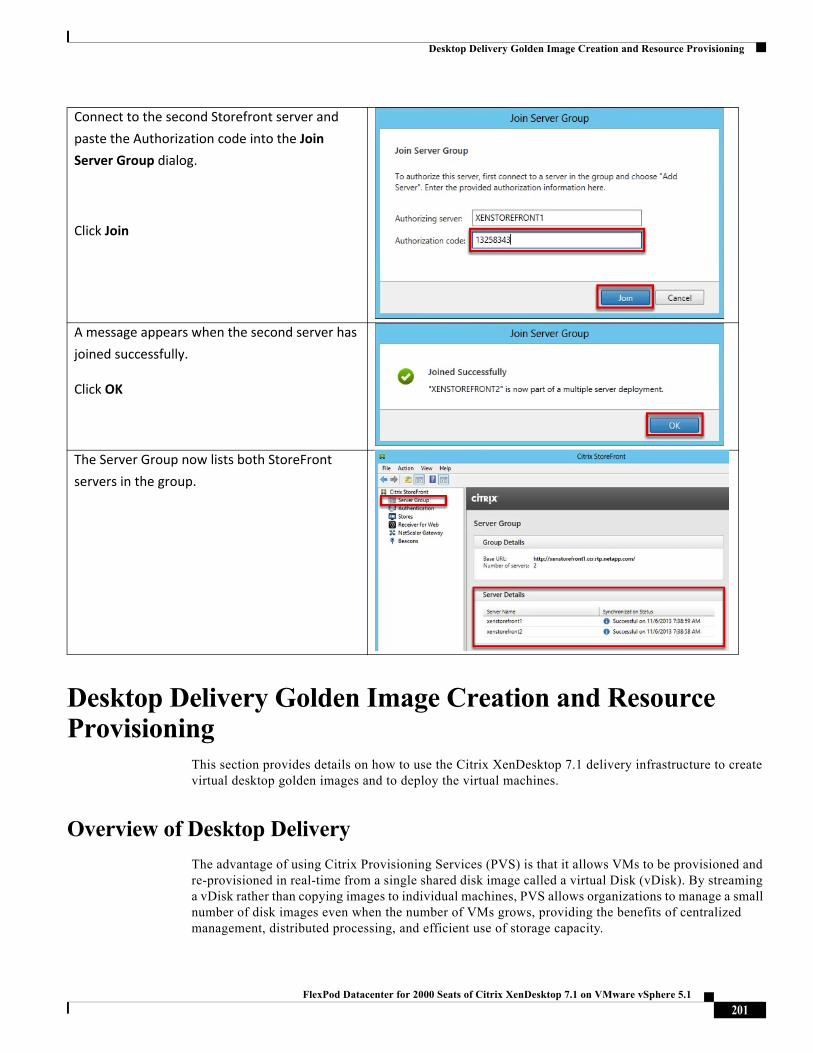
Desktop Delivery Golden Image Creation and Resource Provisioning
Desktop Delivery Golden Image Creation and Resource Provisioning
This section provides details on how to use the Citrix XenDesktop 7.1 delivery infrastructure to create virtual desktop golden images and to deploy the virtual machines.
Overview of Desktop Delivery
The advantage of using Citrix Provisioning Services (PVS) is that it allows VMs to be provisioned and re-provisioned in real-time from a single shared disk image called a virtual Disk (vDisk). By streaming a vDisk rather than copying images to individual machines, PVS allows organizations to manage a small number of disk images even when the number of VMs grows, providing the benefits of centralized management, distributed processing, and efficient use of storage capacity.
Connect to the second Storefront server and
paste the Authorization code into the Join
Server Group dialog.
Click Join
A message appears when the second server has
joined successfully.
Click OK
The Server Group now lists both StoreFront
servers in the group.
201FlexPod Datacenter for 2000 Seats of Citrix XenDesktop 7.1 on VMware vSphere 5.1
Desktop Delivery Golden Image Creation and Resource Provisioning
In most implementations, a single vDisk provides a standardized image to multiple target devices. Multiple PVS servers in the same farm can stream the same vDisk image to thousands of target devices. Virtual desktop environments can be customized through the use of write caches and by personalizing user settings though Citrix User Profile Management.
This section describes the installation and configuration tasks required to create standardized master vDisk images using PVS. This section also discusses write cache sizing and placement considerations, and how policies in Citrix User Profile Management can be configured to further personalize user desktops.
Overview of PVS vDisk Image Management
After installing and configuring PVS components, a vDisk is created from a device's hard drive by taking a snapshot of the OS and application image, and then storing that image as a vDisk file on the network. vDisks can exist on a Provisioning Server, file share, or in larger deployments (as in this CVD) on a storage system with which the Provisioning Server can communicate (through iSCSI, SAN, NAS, and CIFS). A PVS server can access many stored vDisks, and each vDisk can be several gigabytes in size. For this solution, the vDisk was stored on a CIFS share located on the NetApp storage.
vDisks can be assigned to a single target device in Private Image Mode, or to multiple target devices in Standard Image Mode. In Standard Image mode, the vDisk is read-only, which means that multiple target devices can stream from a single vDisk image simultaneously. Standard Image mode reduces the complexity of vDisk management and the amount of storage required since images are shared. In contrast, when a vDisk is configured to use Private Image Mode, the vDisk is read/write and only one target device can access the vDisk at a time.
When a vDisk is configured in Standard Image mode, each time a target device boots, it always boots from a "clean" vDisk image. Each target device then maintains a Write Cache to store any writes that the operating system needs to make, such as the installation of user-specific data or applications. Each virtual desktop is assigned a Write Cache disk (a differencing disk) where changes to the default image are recorded. Used by the virtual Windows operating system throughout its working life cycle, the Write Cache is written to a dedicated virtual hard disk created by thin provisioning and attached to each new virtual desktop.
Overview - Golden Image Creation
For this CVD, PVS supplies these master (or "golden") vDisk images to the target devices:
Table 27 Golden Image Description
To build the vDisk images, OS images of Microsoft Windows 7 and Windows Server 2012, along with additional software, were initially installed and prepared as standard virtual machines on vSphere. These master target VMs (called XENHVD and XENHDS) were then converted into a separate Citrix PVS vDisk files. Citrix PVS and the XenDesktop Delivery Controllers use the golden vDisk images to instantiate new desktop virtual machines on vSphere.
vDisk Name vDisk Location DescriptionXenHVD \\172.20.48.10\userdata\Store The PVS golden image of Microsoft Windows 7 for
Hosted Virtual Desktops.XenHSD \\172.20.48.10\userdata\Store The PVS golden image of Microsoft Windows Server
2012 for Hosted Shared Desktops.
202FlexPod Datacenter for 2000 Seats of Citrix XenDesktop 7.1 on VMware vSphere 5.1
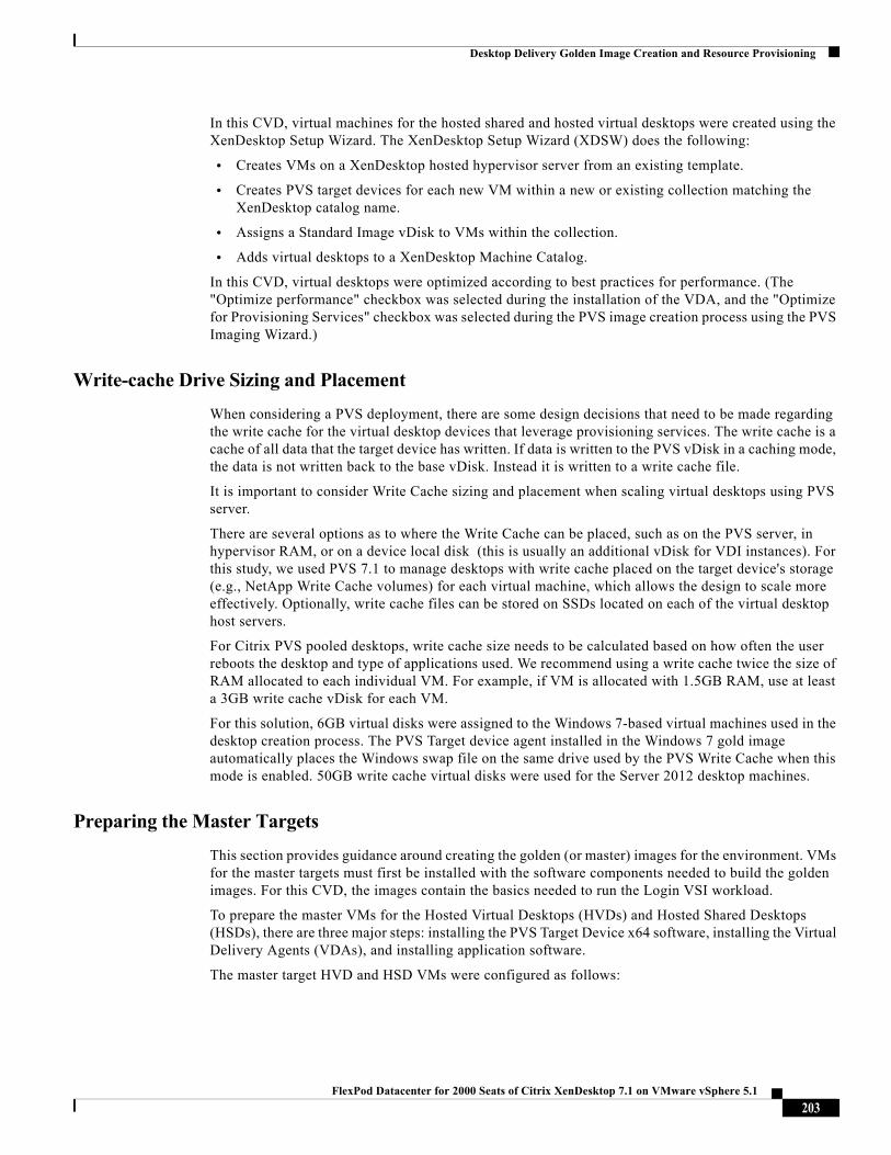
Desktop Delivery Golden Image Creation and Resource Provisioning
In this CVD, virtual machines for the hosted shared and hosted virtual desktops were created using the XenDesktop Setup Wizard. The XenDesktop Setup Wizard (XDSW) does the following:
• Creates VMs on a XenDesktop hosted hypervisor server from an existing template.
• Creates PVS target devices for each new VM within a new or existing collection matching the XenDesktop catalog name.
• Assigns a Standard Image vDisk to VMs within the collection.
• Adds virtual desktops to a XenDesktop Machine Catalog.
In this CVD, virtual desktops were optimized according to best practices for performance. (The "Optimize performance" checkbox was selected during the installation of the VDA, and the "Optimize for Provisioning Services" checkbox was selected during the PVS image creation process using the PVS Imaging Wizard.)
Write-cache Drive Sizing and Placement
When considering a PVS deployment, there are some design decisions that need to be made regarding the write cache for the virtual desktop devices that leverage provisioning services. The write cache is a cache of all data that the target device has written. If data is written to the PVS vDisk in a caching mode, the data is not written back to the base vDisk. Instead it is written to a write cache file.
It is important to consider Write Cache sizing and placement when scaling virtual desktops using PVS server.
There are several options as to where the Write Cache can be placed, such as on the PVS server, in hypervisor RAM, or on a device local disk (this is usually an additional vDisk for VDI instances). For this study, we used PVS 7.1 to manage desktops with write cache placed on the target device's storage (e.g., NetApp Write Cache volumes) for each virtual machine, which allows the design to scale more effectively. Optionally, write cache files can be stored on SSDs located on each of the virtual desktop host servers.
For Citrix PVS pooled desktops, write cache size needs to be calculated based on how often the user reboots the desktop and type of applications used. We recommend using a write cache twice the size of RAM allocated to each individual VM. For example, if VM is allocated with 1.5GB RAM, use at least a 3GB write cache vDisk for each VM.
For this solution, 6GB virtual disks were assigned to the Windows 7-based virtual machines used in the desktop creation process. The PVS Target device agent installed in the Windows 7 gold image automatically places the Windows swap file on the same drive used by the PVS Write Cache when this mode is enabled. 50GB write cache virtual disks were used for the Server 2012 desktop machines.
Preparing the Master Targets
This section provides guidance around creating the golden (or master) images for the environment. VMs for the master targets must first be installed with the software components needed to build the golden images. For this CVD, the images contain the basics needed to run the Login VSI workload.
To prepare the master VMs for the Hosted Virtual Desktops (HVDs) and Hosted Shared Desktops (HSDs), there are three major steps: installing the PVS Target Device x64 software, installing the Virtual Delivery Agents (VDAs), and installing application software.
The master target HVD and HSD VMs were configured as follows:
203FlexPod Datacenter for 2000 Seats of Citrix XenDesktop 7.1 on VMware vSphere 5.1
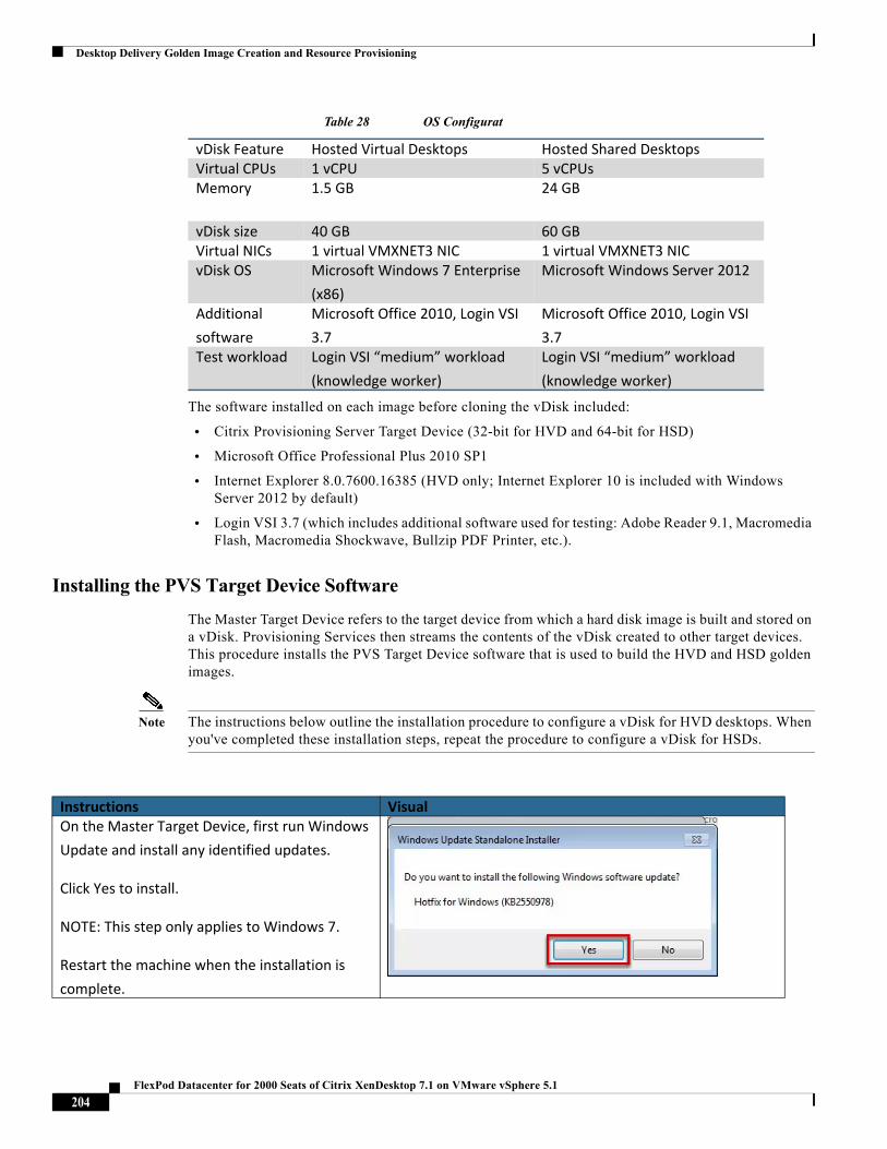
Desktop Delivery Golden Image Creation and Resource Provisioning
Table 28 OS Configurat
The software installed on each image before cloning the vDisk included:
• Citrix Provisioning Server Target Device (32-bit for HVD and 64-bit for HSD)
• Microsoft Office Professional Plus 2010 SP1
• Internet Explorer 8.0.7600.16385 (HVD only; Internet Explorer 10 is included with Windows Server 2012 by default)
• Login VSI 3.7 (which includes additional software used for testing: Adobe Reader 9.1, Macromedia Flash, Macromedia Shockwave, Bullzip PDF Printer, etc.).
Installing the PVS Target Device Software
The Master Target Device refers to the target device from which a hard disk image is built and stored on a vDisk. Provisioning Services then streams the contents of the vDisk created to other target devices. This procedure installs the PVS Target Device software that is used to build the HVD and HSD golden images.
Note The instructions below outline the installation procedure to configure a vDisk for HVD desktops. When you've completed these installation steps, repeat the procedure to configure a vDisk for HSDs.
vDisk Feature Hosted Virtual Desktops Hosted Shared DesktopsVirtual CPUs 1 vCPU 5 vCPUsMemory 1.5 GB 24 GB
vDisk size 40 GB 60 GBVirtual NICs 1 virtual VMXNET3 NIC 1 virtual VMXNET3 NICvDisk OS Microsoft Windows 7 Enterprise
(x86)
Microsoft Windows Server 2012
Additional
software
Microsoft Office 2010, Login VSI
3.7
Microsoft Office 2010, Login VSI
3.7Test workload Login VSI “medium” workload
(knowledge worker)
Login VSI “medium” workload
(knowledge worker)
Instructions VisualOn the Master Target Device, first run Windows
Update and install any identified updates.
Click Yes to install.
NOTE: This step only applies to Windows 7.
Restart the machine when the installation is
complete.
204FlexPod Datacenter for 2000 Seats of Citrix XenDesktop 7.1 on VMware vSphere 5.1
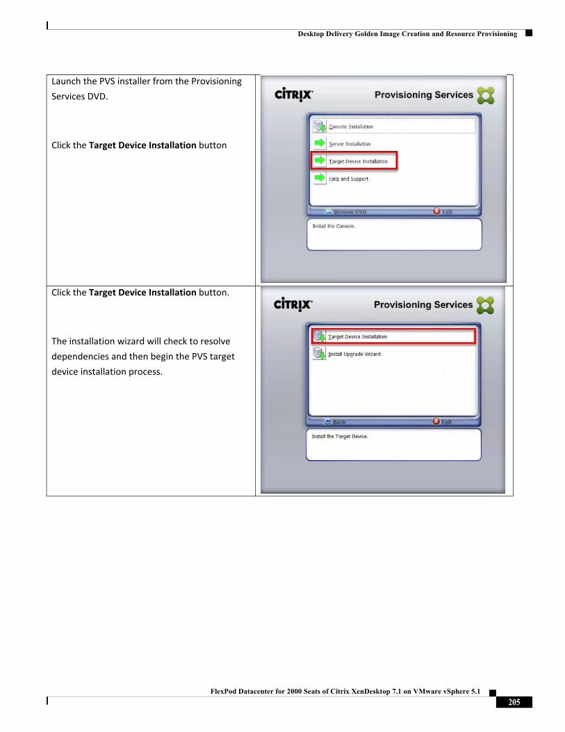
Desktop Delivery Golden Image Creation and Resource Provisioning
Launch the PVS installer from the Provisioning
Services DVD.
Click the Target Device Installation button
Click the Target Device Installation button.
The installation wizard will check to resolve
dependencies and then begin the PVS target
device installation process.
205FlexPod Datacenter for 2000 Seats of Citrix XenDesktop 7.1 on VMware vSphere 5.1
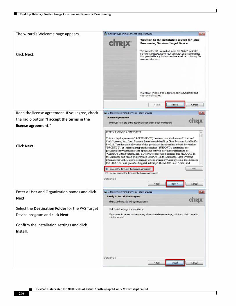
Desktop Delivery Golden Image Creation and Resource Provisioning
The wizard's Welcome page appears.
Click Next.
Read the license agreement. If you agree, check
the radio button “I accept the terms in the
license agreement.”
Click Next
Enter a User and Organization names and click
Next.
Select the Destination Folder for the PVS Target
Device program and click Next.
Confirm the installation settings and click
Install.
206FlexPod Datacenter for 2000 Seats of Citrix XenDesktop 7.1 on VMware vSphere 5.1
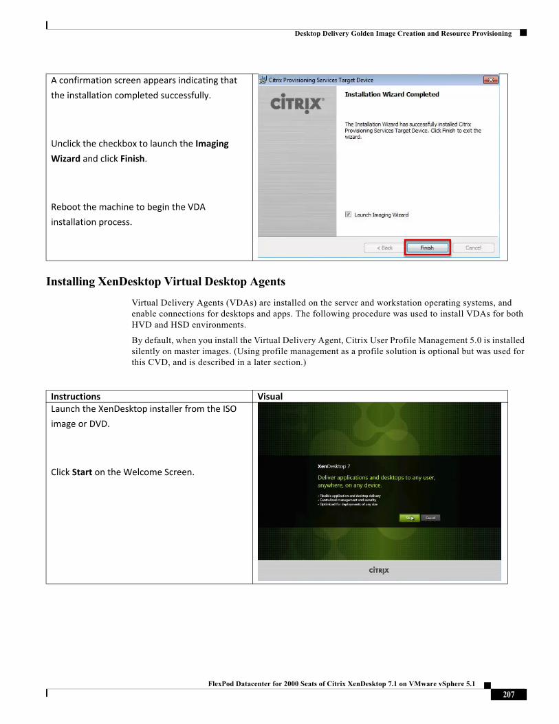
Desktop Delivery Golden Image Creation and Resource Provisioning
Installing XenDesktop Virtual Desktop Agents
Virtual Delivery Agents (VDAs) are installed on the server and workstation operating systems, and enable connections for desktops and apps. The following procedure was used to install VDAs for both HVD and HSD environments.
By default, when you install the Virtual Delivery Agent, Citrix User Profile Management 5.0 is installed silently on master images. (Using profile management as a profile solution is optional but was used for this CVD, and is described in a later section.)
A confirmation screen appears indicating that
the installation completed successfully.
Unclick the checkbox to launch the Imaging
Wizard and click Finish.
Reboot the machine to begin the VDA
installation process.
Instructions VisualLaunch the XenDesktop installer from the ISO
image or DVD.
Click Start on the Welcome Screen.
207FlexPod Datacenter for 2000 Seats of Citrix XenDesktop 7.1 on VMware vSphere 5.1
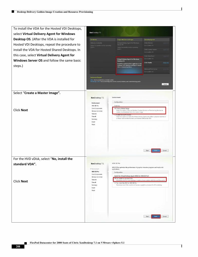
Desktop Delivery Golden Image Creation and Resource Provisioning
To install the VDA for the Hosted VDI Desktops,
select Virtual Delivery Agent for Windows
Desktop OS. (After the VDA is installed for
Hosted VDI Desktops, repeat the procedure to
install the VDA for Hosted Shared Desktops. In
this case, select Virtual Delivery Agent for
Windows Server OS and follow the same basic
steps.)
Select “Create a Master Image”.
Click Next
For the HVD vDisk, select “No, install the
standard VDA”.
Click Next
208FlexPod Datacenter for 2000 Seats of Citrix XenDesktop 7.1 on VMware vSphere 5.1
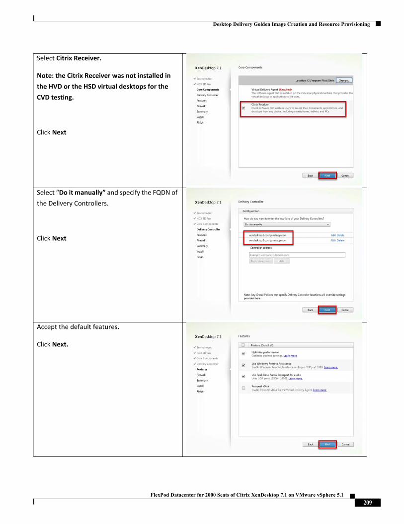
Desktop Delivery Golden Image Creation and Resource Provisioning
Select Citrix Receiver.
Note: the Citrix Receiver was not installed in
the HVD or the HSD virtual desktops for the
CVD testing.
Click Next
Select “Do it manually” and specify the FQDN of
the Delivery Controllers.
Click Next
Accept the default features.
Click Next.
209FlexPod Datacenter for 2000 Seats of Citrix XenDesktop 7.1 on VMware vSphere 5.1
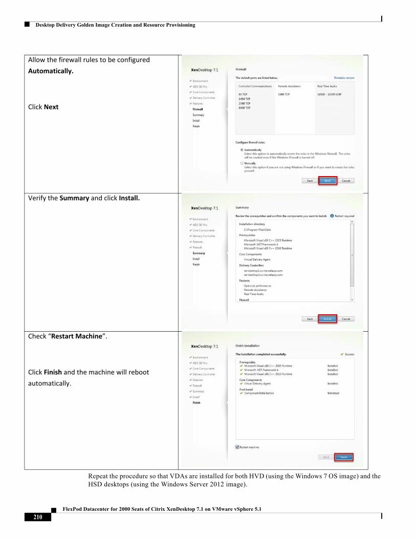
Desktop Delivery Golden Image Creation and Resource Provisioning
Repeat the procedure so that VDAs are installed for both HVD (using the Windows 7 OS image) and the HSD desktops (using the Windows Server 2012 image).
Allow the firewall rules to be configured
Automatically.
Click Next
Verify the Summary and click Install.
Check “Restart Machine”.
Click Finish and the machine will reboot
automatically.
210FlexPod Datacenter for 2000 Seats of Citrix XenDesktop 7.1 on VMware vSphere 5.1
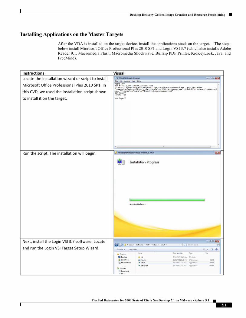
Desktop Delivery Golden Image Creation and Resource Provisioning
Installing Applications on the Master Targets
After the VDA is installed on the target device, install the applications stack on the target. The steps below install Microsoft Office Professional Plus 2010 SP1 and Login VSI 3.7 (which also installs Adobe Reader 9.1, Macromedia Flash, Macromedia Shockwave, Bullzip PDF Printer, KidKeyLock, Java, and FreeMind).
Instructions VisualLocate the installation wizard or script to install
Microsoft Office Professional Plus 2010 SP1. In
this CVD, we used the installation script shown
to install it on the target.
Run the script. The installation will begin.
Next, install the Login VSI 3.7 software. Locate
and run the Login VSI Target Setup Wizard.
211FlexPod Datacenter for 2000 Seats of Citrix XenDesktop 7.1 on VMware vSphere 5.1
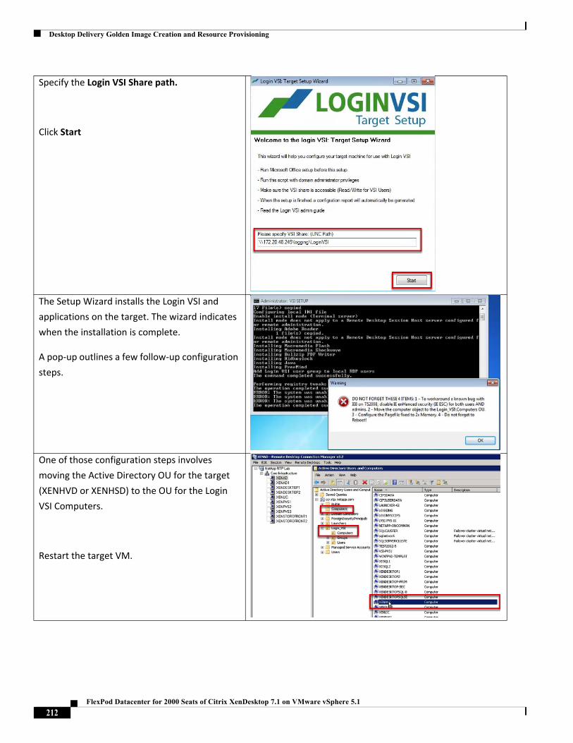
Desktop Delivery Golden Image Creation and Resource Provisioning
Specify the Login VSI Share path.
Click Start
The Setup Wizard installs the Login VSI and
applications on the target. The wizard indicates
when the installation is complete.
A pop‐up outlines a few follow‐up configuration
steps.
One of those configuration steps involves
moving the Active Directory OU for the target
(XENHVD or XENHSD) to the OU for the Login
VSI Computers.
Restart the target VM.
212FlexPod Datacenter for 2000 Seats of Citrix XenDesktop 7.1 on VMware vSphere 5.1
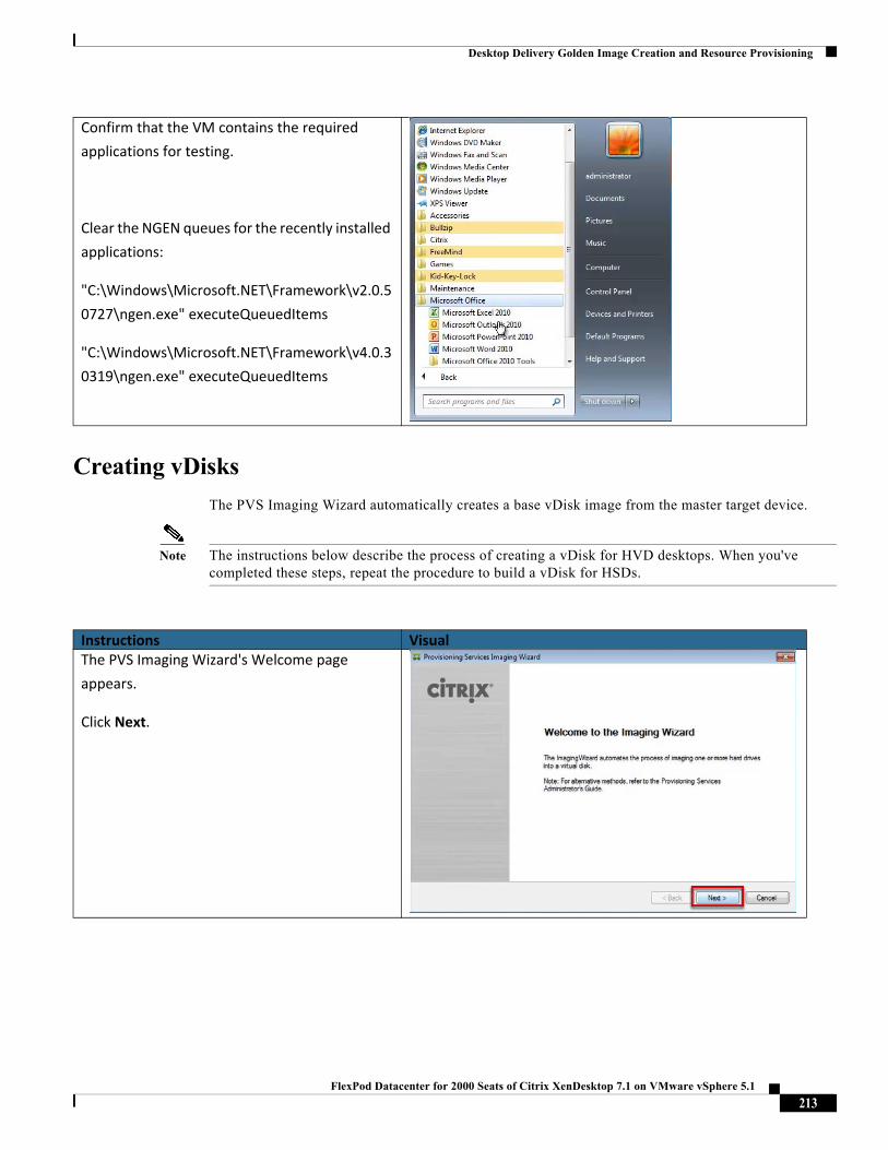
Desktop Delivery Golden Image Creation and Resource Provisioning
Creating vDisks
The PVS Imaging Wizard automatically creates a base vDisk image from the master target device.
Note The instructions below describe the process of creating a vDisk for HVD desktops. When you've completed these steps, repeat the procedure to build a vDisk for HSDs.
Confirm that the VM contains the required
applications for testing.
Clear the NGEN queues for the recently installed
applications:
"C:\Windows\Microsoft.NET\Framework\v2.0.5
0727\ngen.exe" executeQueuedItems
"C:\Windows\Microsoft.NET\Framework\v4.0.3
0319\ngen.exe" executeQueuedItems
Instructions VisualThe PVS Imaging Wizard's Welcome page
appears.
Click Next.
213FlexPod Datacenter for 2000 Seats of Citrix XenDesktop 7.1 on VMware vSphere 5.1
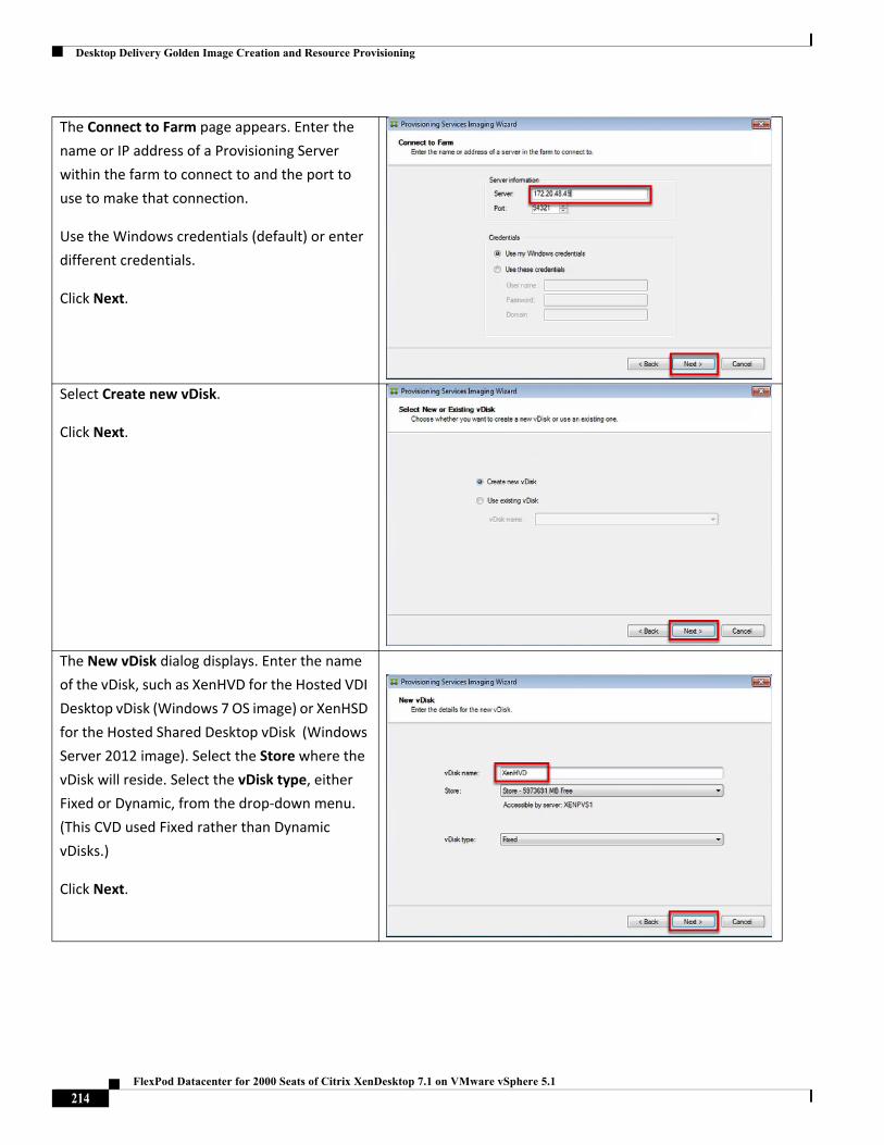
Desktop Delivery Golden Image Creation and Resource Provisioning
The Connect to Farm page appears. Enter the
name or IP address of a Provisioning Server
within the farm to connect to and the port to
use to make that connection.
Use the Windows credentials (default) or enter
different credentials.
Click Next.
Select Create new vDisk.
Click Next.
The New vDisk dialog displays. Enter the name
of the vDisk, such as XenHVD for the Hosted VDI
Desktop vDisk (Windows 7 OS image) or XenHSD
for the Hosted Shared Desktop vDisk (Windows
Server 2012 image). Select the Store where the
vDisk will reside. Select the vDisk type, either
Fixed or Dynamic, from the drop‐down menu.
(This CVD used Fixed rather than Dynamic
vDisks.)
Click Next.
214FlexPod Datacenter for 2000 Seats of Citrix XenDesktop 7.1 on VMware vSphere 5.1
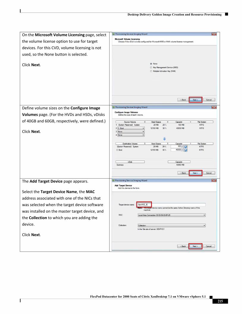
Desktop Delivery Golden Image Creation and Resource Provisioning
On the Microsoft Volume Licensing page, select
the volume license option to use for target
devices. For this CVD, volume licensing is not
used, so the None button is selected.
Click Next.
Define volume sizes on the Configure Image
Volumes page. (For the HVDs and HSDs, vDisks
of 40GB and 60GB, respectively, were defined.)
Click Next.
The Add Target Device page appears.
Select the Target Device Name, the MAC
address associated with one of the NICs that
was selected when the target device software
was installed on the master target device, and
the Collection to which you are adding the
device.
Click Next.
215FlexPod Datacenter for 2000 Seats of Citrix XenDesktop 7.1 on VMware vSphere 5.1
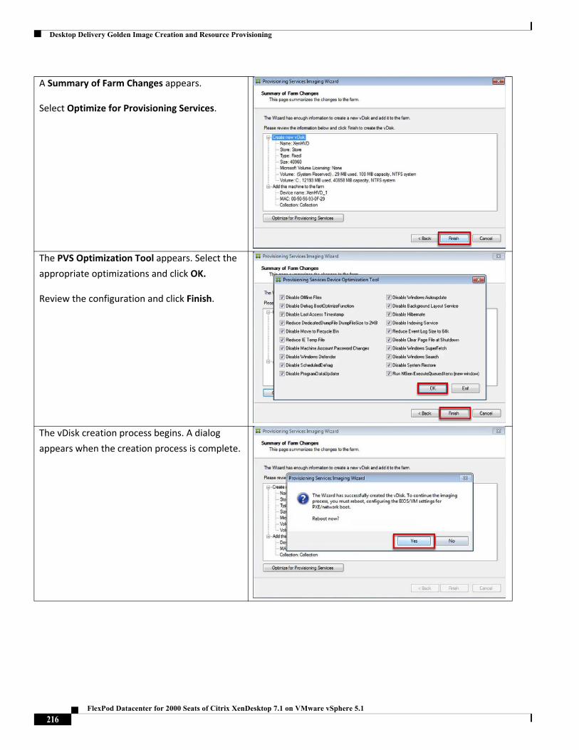
Desktop Delivery Golden Image Creation and Resource Provisioning
A Summary of Farm Changes appears.
Select Optimize for Provisioning Services.
The PVS Optimization Tool appears. Select the
appropriate optimizations and click OK.
Review the configuration and click Finish.
The vDisk creation process begins. A dialog
appears when the creation process is complete.
216FlexPod Datacenter for 2000 Seats of Citrix XenDesktop 7.1 on VMware vSphere 5.1
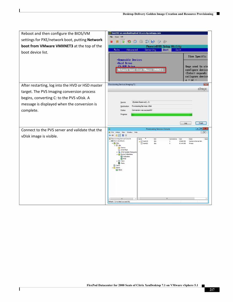
Desktop Delivery Golden Image Creation and Resource Provisioning
Reboot and then configure the BIOS/VM
settings for PXE/network boot, putting Network
boot from VMware VMXNET3 at the top of the
boot device list.
After restarting, log into the HVD or HSD master
target. The PVS Imaging conversion process
begins, converting C: to the PVS vDisk. A
message is displayed when the conversion is
complete.
Connect to the PVS server and validate that the
vDisk image is visible.
217FlexPod Datacenter for 2000 Seats of Citrix XenDesktop 7.1 on VMware vSphere 5.1
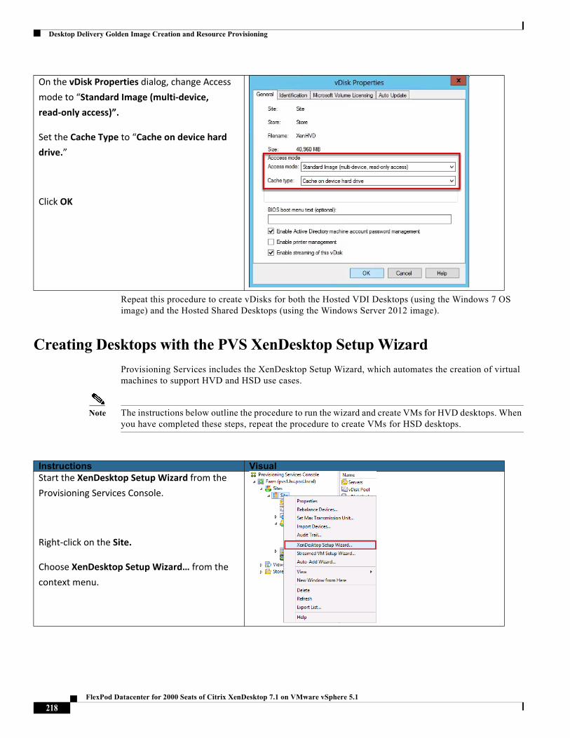
Desktop Delivery Golden Image Creation and Resource Provisioning
Repeat this procedure to create vDisks for both the Hosted VDI Desktops (using the Windows 7 OS image) and the Hosted Shared Desktops (using the Windows Server 2012 image).
Creating Desktops with the PVS XenDesktop Setup Wizard
Provisioning Services includes the XenDesktop Setup Wizard, which automates the creation of virtual machines to support HVD and HSD use cases.
Note The instructions below outline the procedure to run the wizard and create VMs for HVD desktops. When you have completed these steps, repeat the procedure to create VMs for HSD desktops.
On the vDisk Properties dialog, change Access
mode to “Standard Image (multi‐device,
read‐only access)”.
Set the Cache Type to “Cache on device hard
drive.”
Click OK
Instructions VisualStart the XenDesktop Setup Wizard from the
Provisioning Services Console.
Right‐click on the Site.
Choose XenDesktop Setup Wizard… from the
context menu.
218FlexPod Datacenter for 2000 Seats of Citrix XenDesktop 7.1 on VMware vSphere 5.1
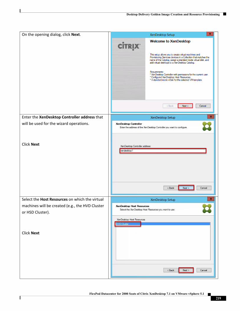
Desktop Delivery Golden Image Creation and Resource Provisioning
On the opening dialog, click Next.
Enter the XenDesktop Controller address that
will be used for the wizard operations.
Click Next
Select the Host Resources on which the virtual
machines will be created (e.g., the HVD Cluster
or HSD Cluster).
Click Next
219FlexPod Datacenter for 2000 Seats of Citrix XenDesktop 7.1 on VMware vSphere 5.1
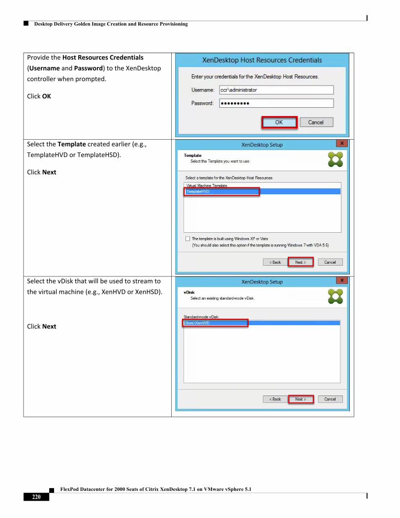
Desktop Delivery Golden Image Creation and Resource Provisioning
Provide the Host Resources Credentials
(Username and Password) to the XenDesktop
controller when prompted.
Click OK
Select the Template created earlier (e.g.,
TemplateHVD or TemplateHSD).
Click Next
Select the vDisk that will be used to stream to
the virtual machine (e.g., XenHVD or XenHSD).
Click Next
220FlexPod Datacenter for 2000 Seats of Citrix XenDesktop 7.1 on VMware vSphere 5.1
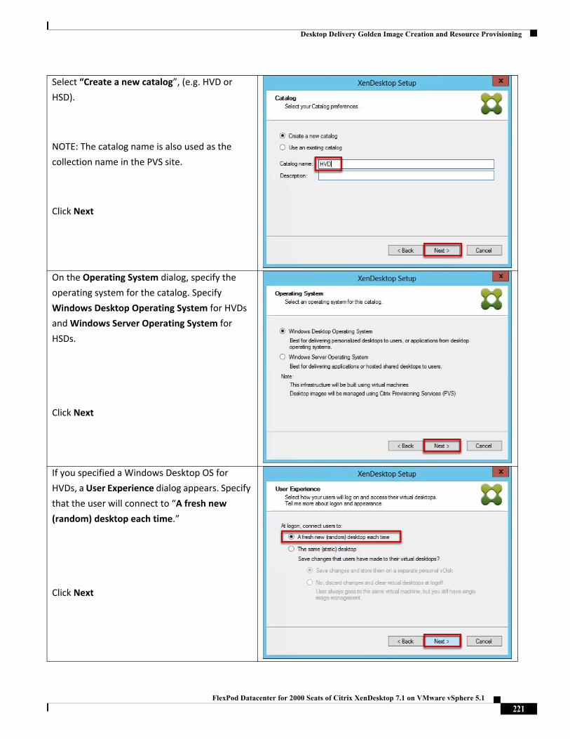
Desktop Delivery Golden Image Creation and Resource Provisioning
Select “Create a new catalog”, (e.g. HVD or
HSD).
NOTE: The catalog name is also used as the
collection name in the PVS site.
Click Next
On the Operating System dialog, specify the
operating system for the catalog. Specify
Windows Desktop Operating System for HVDs
and Windows Server Operating System for
HSDs.
Click Next
If you specified a Windows Desktop OS for
HVDs, a User Experience dialog appears. Specify
that the user will connect to “A fresh new
(random) desktop each time.”
Click Next
221FlexPod Datacenter for 2000 Seats of Citrix XenDesktop 7.1 on VMware vSphere 5.1
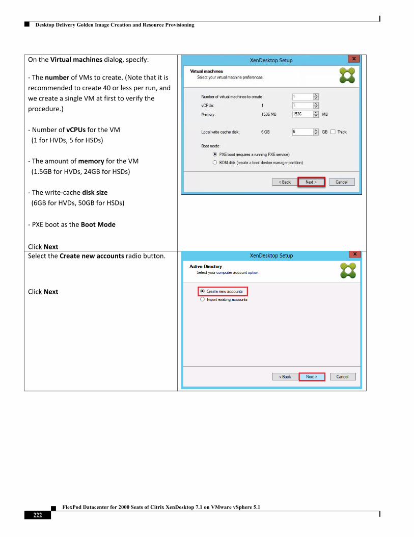
Desktop Delivery Golden Image Creation and Resource Provisioning
On the Virtual machines dialog, specify:
‐ The number of VMs to create. (Note that it is
recommended to create 40 or less per run, and
we create a single VM at first to verify the
procedure.)
‐ Number of vCPUs for the VM
(1 for HVDs, 5 for HSDs)
‐ The amount of memory for the VM
(1.5GB for HVDs, 24GB for HSDs)
‐ The write‐cache disk size
(6GB for HVDs, 50GB for HSDs)
‐ PXE boot as the Boot Mode
Click NextSelect the Create new accounts radio button.
Click Next
222FlexPod Datacenter for 2000 Seats of Citrix XenDesktop 7.1 on VMware vSphere 5.1
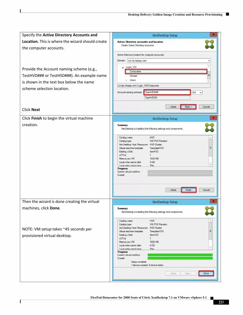
Desktop Delivery Golden Image Creation and Resource Provisioning
Specify the Active Directory Accounts and
Location. This is where the wizard should create
the computer accounts.
Provide the Account naming scheme (e.g.,
TestHVD### or TestHSD###). An example name
is shown in the text box below the name
scheme selection location.
Click Next
Click Finish to begin the virtual machine
creation.
Then the wizard is done creating the virtual
machines, click Done.
NOTE: VM setup takes ~45 seconds per
provisioned virtual desktop.
223FlexPod Datacenter for 2000 Seats of Citrix XenDesktop 7.1 on VMware vSphere 5.1
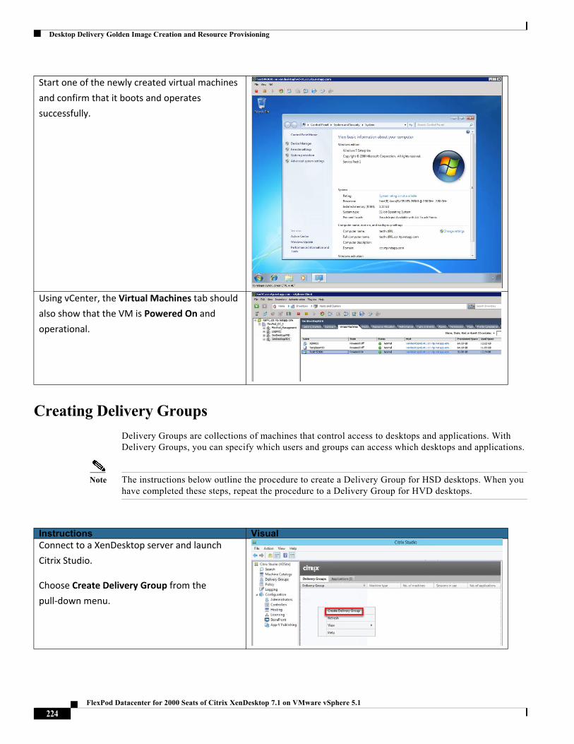
Desktop Delivery Golden Image Creation and Resource Provisioning
Creating Delivery Groups
Delivery Groups are collections of machines that control access to desktops and applications. With Delivery Groups, you can specify which users and groups can access which desktops and applications.
Note The instructions below outline the procedure to create a Delivery Group for HSD desktops. When you have completed these steps, repeat the procedure to a Delivery Group for HVD desktops.
Start one of the newly created virtual machines
and confirm that it boots and operates
successfully.
Using vCenter, the Virtual Machines tab should
also show that the VM is Powered On and
operational.
Instructions VisualConnect to a XenDesktop server and launch
Citrix Studio.
Choose Create Delivery Group from the
pull‐down menu.
224FlexPod Datacenter for 2000 Seats of Citrix XenDesktop 7.1 on VMware vSphere 5.1
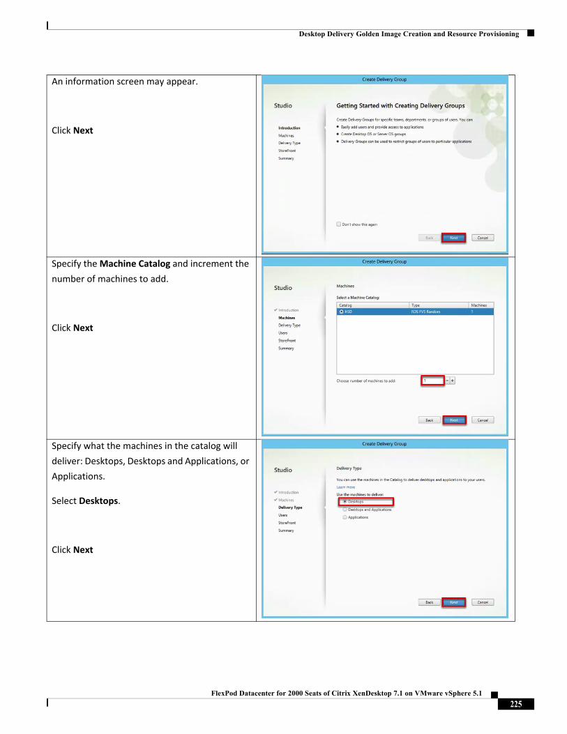
Desktop Delivery Golden Image Creation and Resource Provisioning
An information screen may appear.
Click Next
Specify the Machine Catalog and increment the
number of machines to add.
Click Next
Specify what the machines in the catalog will
deliver: Desktops, Desktops and Applications, or
Applications.
Select Desktops.
Click Next
225FlexPod Datacenter for 2000 Seats of Citrix XenDesktop 7.1 on VMware vSphere 5.1
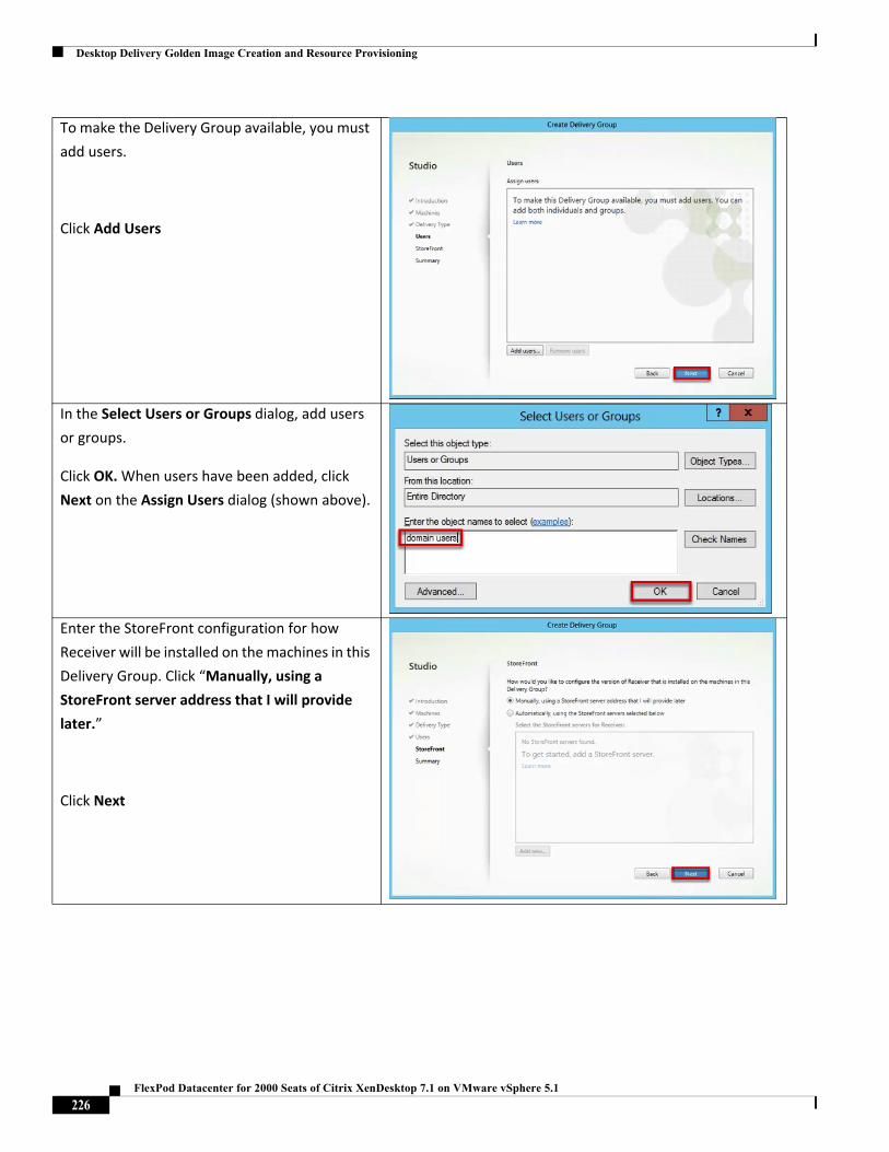
Desktop Delivery Golden Image Creation and Resource Provisioning
To make the Delivery Group available, you must
add users.
Click Add Users
In the Select Users or Groups dialog, add users
or groups.
Click OK. When users have been added, click
Next on the Assign Users dialog (shown above).
Enter the StoreFront configuration for how
Receiver will be installed on the machines in this
Delivery Group. Click “Manually, using a
StoreFront server address that I will provide
later.”
Click Next
226FlexPod Datacenter for 2000 Seats of Citrix XenDesktop 7.1 on VMware vSphere 5.1
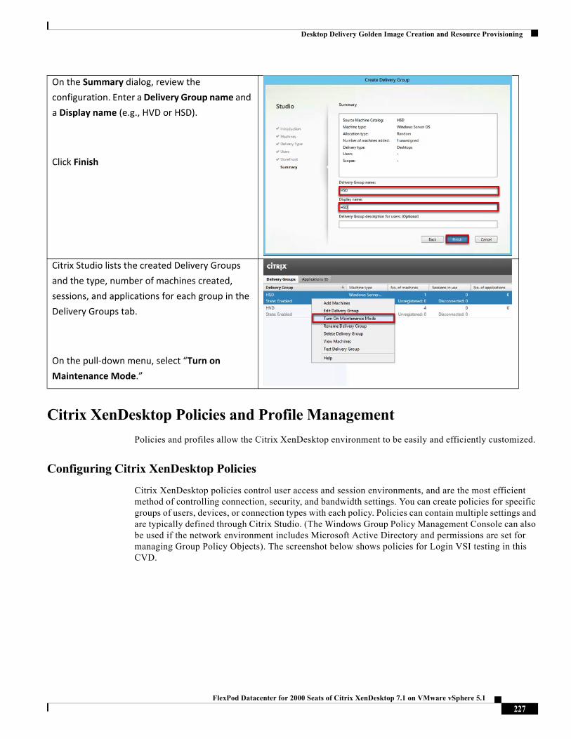
Desktop Delivery Golden Image Creation and Resource Provisioning
Citrix XenDesktop Policies and Profile Management
Policies and profiles allow the Citrix XenDesktop environment to be easily and efficiently customized.
Configuring Citrix XenDesktop Policies
Citrix XenDesktop policies control user access and session environments, and are the most efficient method of controlling connection, security, and bandwidth settings. You can create policies for specific groups of users, devices, or connection types with each policy. Policies can contain multiple settings and are typically defined through Citrix Studio. (The Windows Group Policy Management Console can also be used if the network environment includes Microsoft Active Directory and permissions are set for managing Group Policy Objects). The screenshot below shows policies for Login VSI testing in this CVD.
On the Summary dialog, review the
configuration. Enter a Delivery Group name and
a Display name (e.g., HVD or HSD).
Click Finish
Citrix Studio lists the created Delivery Groups
and the type, number of machines created,
sessions, and applications for each group in the
Delivery Groups tab.
On the pull‐down menu, select “Turn on
Maintenance Mode.”
227FlexPod Datacenter for 2000 Seats of Citrix XenDesktop 7.1 on VMware vSphere 5.1
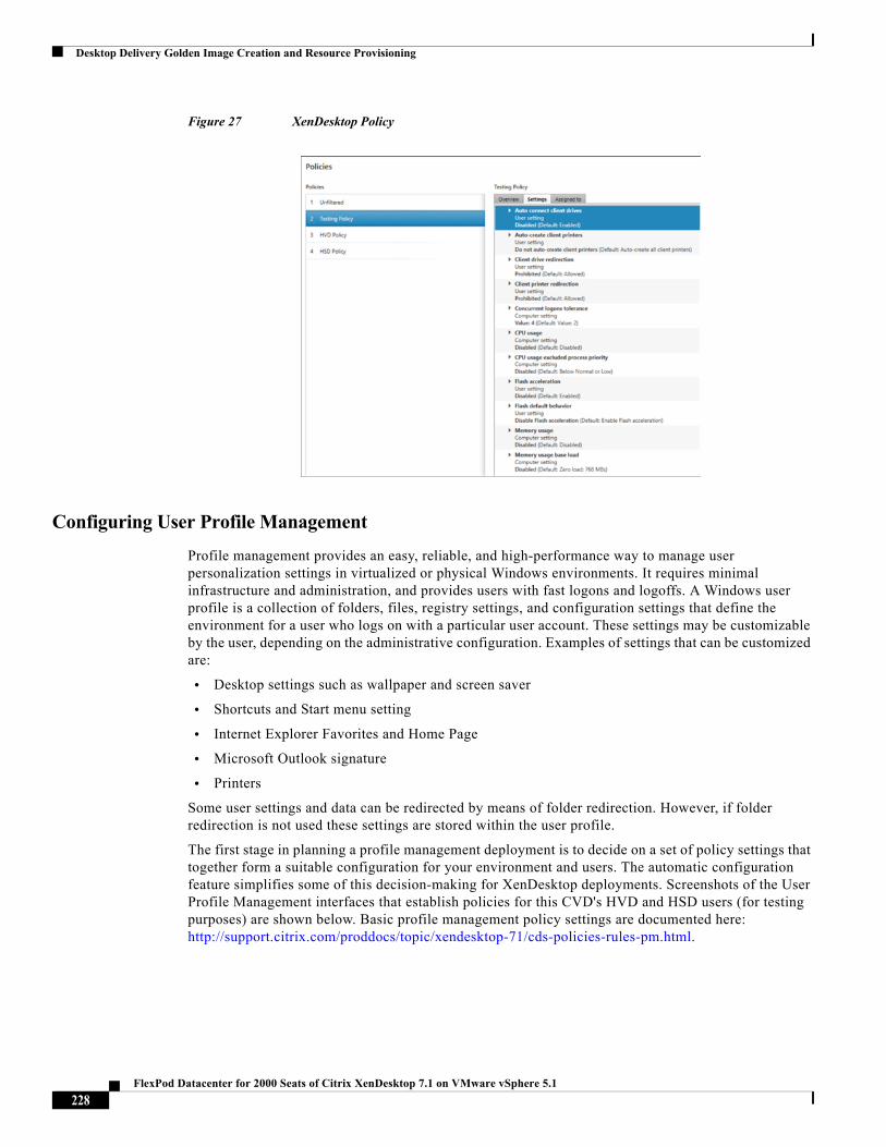
Desktop Delivery Golden Image Creation and Resource Provisioning
Figure 27 XenDesktop Policy
Configuring User Profile Management
Profile management provides an easy, reliable, and high-performance way to manage user personalization settings in virtualized or physical Windows environments. It requires minimal infrastructure and administration, and provides users with fast logons and logoffs. A Windows user profile is a collection of folders, files, registry settings, and configuration settings that define the environment for a user who logs on with a particular user account. These settings may be customizable by the user, depending on the administrative configuration. Examples of settings that can be customized are:
• Desktop settings such as wallpaper and screen saver
• Shortcuts and Start menu setting
• Internet Explorer Favorites and Home Page
• Microsoft Outlook signature
• Printers
Some user settings and data can be redirected by means of folder redirection. However, if folder redirection is not used these settings are stored within the user profile.
The first stage in planning a profile management deployment is to decide on a set of policy settings that together form a suitable configuration for your environment and users. The automatic configuration feature simplifies some of this decision-making for XenDesktop deployments. Screenshots of the User Profile Management interfaces that establish policies for this CVD's HVD and HSD users (for testing purposes) are shown below. Basic profile management policy settings are documented here: http://support.citrix.com/proddocs/topic/xendesktop-71/cds-policies-rules-pm.html.
228FlexPod Datacenter for 2000 Seats of Citrix XenDesktop 7.1 on VMware vSphere 5.1
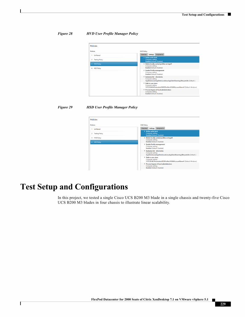
Test Setup and Configurations
Figure 28 HVD User Profile Manager Policy
Figure 29 HSD User Profile Manager Policy
Test Setup and ConfigurationsIn this project, we tested a single Cisco UCS B200 M3 blade in a single chassis and twenty-five Cisco UCS B200 M3 blades in four chassis to illustrate linear scalability.
229FlexPod Datacenter for 2000 Seats of Citrix XenDesktop 7.1 on VMware vSphere 5.1
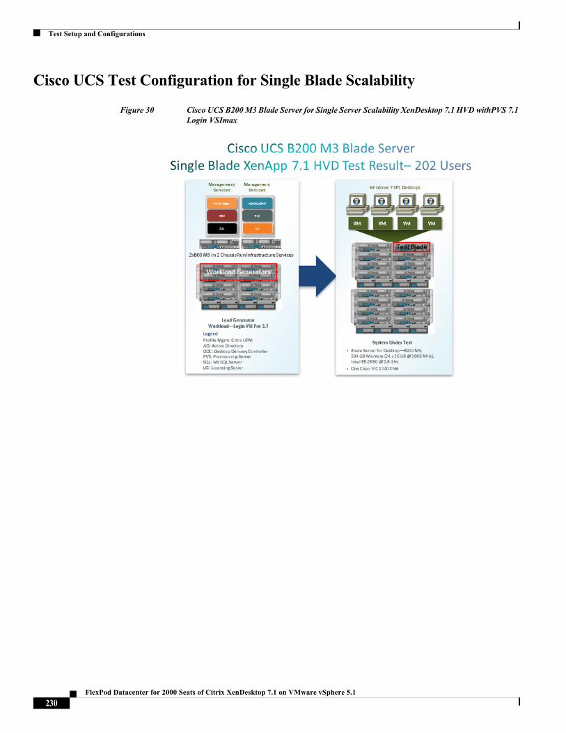
Test Setup and Configurations
Cisco UCS Test Configuration for Single Blade Scalability
Figure 30 Cisco UCS B200 M3 Blade Server for Single Server Scalability XenDesktop 7.1 HVD withPVS 7.1 Login VSImax
230FlexPod Datacenter for 2000 Seats of Citrix XenDesktop 7.1 on VMware vSphere 5.1
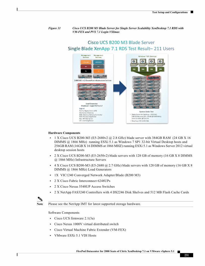
Test Setup and Configurations
Figure 31 Cisco UCS B200 M3 Blade Server for Single Server Scalability XenDesktop 7.1 RDS with VM-FEX and PVS 7.1 Login VSImax
Hardware Components
• 1 X Cisco UCS B200-M3 (E5-2680v2 @ 2.8 GHz) blade server with 384GB RAM (24 GB X 16 DIMMS @ 1866 MHz) running ESXi 5.1 as Windows 7 SP1 32-bit Virtual Desktop hosts and 256GB RAM (16GB X 16 DIMMS at 1866 MHZ) running ESXi 5.1 as Windows Server 2012 virtual desktop session hosts
• 2 X Cisco UCS B200-M3 (E5-2650v2) blade servers with 128 GB of memory (16 GB X 8 DIMMS @ 1866 MHz) Infrastructure Servers
• 4 X Cisco UCS B200-M3 (E5-2680 @ 2.7 GHz) blade servers with 128 GB of memory (16 GB X 8 DIMMS @ 1866 MHz) Load Generators
• 1X VIC1240 Converged Network Adapter/Blade (B200 M3)
• 2 X Cisco Fabric Interconnect 6248UPs
• 2 X Cisco Nexus 5548UP Access Switches
• 2 X NetApp FAS3240 Controllers with 4 DS2246 Disk Shelves and 512 MB Flash Cache Cards
Note Please see the NetApp IMT for latest supported storage hardware.
Software Components
• Cisco UCS firmware 2.1(3a)
• Cisco Nexus 1000V virtual distributed switch
• Cisco Virtual Machine Fabric Extender (VM-FEX)
• VMware ESXi 5.1 VDI Hosts
231FlexPod Datacenter for 2000 Seats of Citrix XenDesktop 7.1 on VMware vSphere 5.1
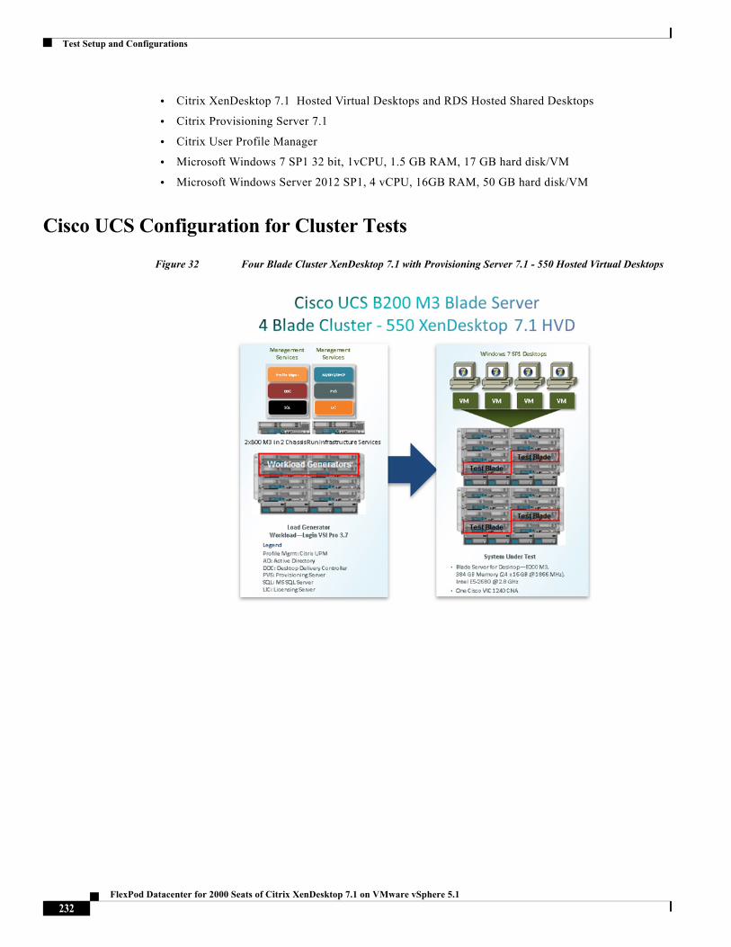
Test Setup and Configurations
• Citrix XenDesktop 7.1 Hosted Virtual Desktops and RDS Hosted Shared Desktops
• Citrix Provisioning Server 7.1
• Citrix User Profile Manager
• Microsoft Windows 7 SP1 32 bit, 1vCPU, 1.5 GB RAM, 17 GB hard disk/VM
• Microsoft Windows Server 2012 SP1, 4 vCPU, 16GB RAM, 50 GB hard disk/VM
Cisco UCS Configuration for Cluster Tests
Figure 32 Four Blade Cluster XenDesktop 7.1 with Provisioning Server 7.1 - 550 Hosted Virtual Desktops
232FlexPod Datacenter for 2000 Seats of Citrix XenDesktop 7.1 on VMware vSphere 5.1
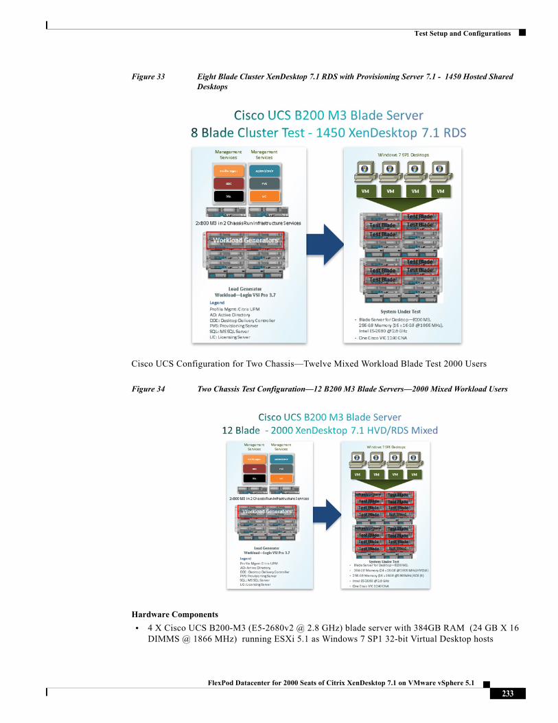
Test Setup and Configurations
Figure 33 Eight Blade Cluster XenDesktop 7.1 RDS with Provisioning Server 7.1 - 1450 Hosted Shared Desktops
Cisco UCS Configuration for Two Chassis—Twelve Mixed Workload Blade Test 2000 Users
Figure 34 Two Chassis Test Configuration—12 B200 M3 Blade Servers—2000 Mixed Workload Users
Hardware Components
• 4 X Cisco UCS B200-M3 (E5-2680v2 @ 2.8 GHz) blade server with 384GB RAM (24 GB X 16 DIMMS @ 1866 MHz) running ESXi 5.1 as Windows 7 SP1 32-bit Virtual Desktop hosts
233FlexPod Datacenter for 2000 Seats of Citrix XenDesktop 7.1 on VMware vSphere 5.1
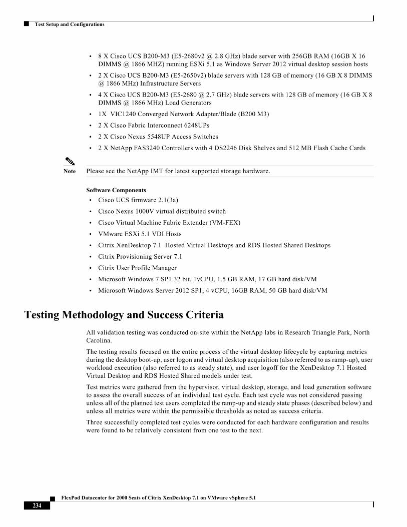
Test Setup and Configurations
• 8 X Cisco UCS B200-M3 (E5-2680v2 @ 2.8 GHz) blade server with 256GB RAM (16GB X 16 DIMMS @ 1866 MHZ) running ESXi 5.1 as Windows Server 2012 virtual desktop session hosts
• 2 X Cisco UCS B200-M3 (E5-2650v2) blade servers with 128 GB of memory (16 GB X 8 DIMMS @ 1866 MHz) Infrastructure Servers
• 4 X Cisco UCS B200-M3 (E5-2680 @ 2.7 GHz) blade servers with 128 GB of memory (16 GB X 8 DIMMS @ 1866 MHz) Load Generators
• 1X VIC1240 Converged Network Adapter/Blade (B200 M3)
• 2 X Cisco Fabric Interconnect 6248UPs
• 2 X Cisco Nexus 5548UP Access Switches
• 2 X NetApp FAS3240 Controllers with 4 DS2246 Disk Shelves and 512 MB Flash Cache Cards
Note Please see the NetApp IMT for latest supported storage hardware.
Software Components
• Cisco UCS firmware 2.1(3a)
• Cisco Nexus 1000V virtual distributed switch
• Cisco Virtual Machine Fabric Extender (VM-FEX)
• VMware ESXi 5.1 VDI Hosts
• Citrix XenDesktop 7.1 Hosted Virtual Desktops and RDS Hosted Shared Desktops
• Citrix Provisioning Server 7.1
• Citrix User Profile Manager
• Microsoft Windows 7 SP1 32 bit, 1vCPU, 1.5 GB RAM, 17 GB hard disk/VM
• Microsoft Windows Server 2012 SP1, 4 vCPU, 16GB RAM, 50 GB hard disk/VM
Testing Methodology and Success Criteria
All validation testing was conducted on-site within the NetApp labs in Research Triangle Park, North Carolina.
The testing results focused on the entire process of the virtual desktop lifecycle by capturing metrics during the desktop boot-up, user logon and virtual desktop acquisition (also referred to as ramp-up), user workload execution (also referred to as steady state), and user logoff for the XenDesktop 7.1 Hosted Virtual Desktop and RDS Hosted Shared models under test.
Test metrics were gathered from the hypervisor, virtual desktop, storage, and load generation software to assess the overall success of an individual test cycle. Each test cycle was not considered passing unless all of the planned test users completed the ramp-up and steady state phases (described below) and unless all metrics were within the permissible thresholds as noted as success criteria.
Three successfully completed test cycles were conducted for each hardware configuration and results were found to be relatively consistent from one test to the next.
234FlexPod Datacenter for 2000 Seats of Citrix XenDesktop 7.1 on VMware vSphere 5.1
Test Setup and Configurations
Load Generation
Within each test environment, load generators were utilized to put demand on the system to simulate multiple users accessing the XenDesktop 7.1 environment and executing a typical end-user workflow. To generate load within the environment, an auxiliary software application was required to generate the end user connection to the XenDesktop 7.1 environment, to provide unique user credentials, to initiate the workload, and to evaluate the end user experience.
In the Hosted VDI test environment, sessions launchers were used simulate multiple users making a direct connection to XenDesktop 7.1 through a Citrix HDX protocol connection.
User Workload Simulation - LoginVSI From Login VSI Inc.
One of the most critical factors of validating a desktop virtualization deployment is identifying a real-world user workload that is easy for customers to replicate and standardized across platforms to allow customers to realistically test the impact of a variety of worker tasks. To accurately represent a real-world user workload, a third-party tool from Login VSI Inc was used throughout the Hosted VDI testing.
The tool has the benefit of taking measurements of the in-session response time, providing an objective way to measure the expected user experience for individual desktop throughout large scale testing, including login storms.
The Login Virtual Session Indexer (Login VSI Inc' Login VSI 3.7) methodology, designed for benchmarking Server Based Computing (SBC) and Virtual Desktop Infrastructure (VDI) environments is completely platform and protocol independent and hence allows customers to easily replicate the testing results in their environment. NOTE: In this testing, we utilized the tool to benchmark our VDI environment only.
Login VSI calculates an index based on the amount of simultaneous sessions that can be run on a single machine.
Login VSI simulates a medium workload user (also known as knowledge worker) running generic applications such as: Microsoft Office 2007 or 2010, Internet Explorer 8 including a Flash video applet and Adobe Acrobat Reader (Note: For the purposes of this test, applications were installed locally, not streamed by ThinApp).
Like real users, the scripted Login VSI session will leave multiple applications open at the same time. The medium workload is the default workload in Login VSI and was used for this testing. This workload emulated a medium knowledge working using Office, IE, printing and PDF viewing.
• When a session has been started the medium workload will repeat every 12 minutes.
• During each loop the response time is measured every 2 minutes.
• The medium workload opens up to 5 apps simultaneously.
• The type rate is 160ms for each character.
• Approximately 2 minutes of idle time is included to simulate real-world users.
Each loop will open and use:
• Outlook 2007/2010, browse 10 messages.
• Internet Explorer, one instance is left open (BBC.co.uk), one instance is browsed to Wired.com, Lonelyplanet.com and heavy
• 480 p Flash application gettheglass.com.
• Word 2007/2010, one instance to measure response time, one instance to review and edit document.
235FlexPod Datacenter for 2000 Seats of Citrix XenDesktop 7.1 on VMware vSphere 5.1
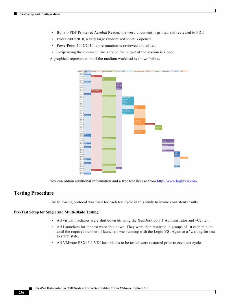
Test Setup and Configurations
• Bullzip PDF Printer & Acrobat Reader, the word document is printed and reviewed to PDF.
• Excel 2007/2010, a very large randomized sheet is opened.
• PowerPoint 2007/2010, a presentation is reviewed and edited.
• 7-zip: using the command line version the output of the session is zipped.
A graphical representation of the medium workload is shown below.
You can obtain additional information and a free test license from http://www.loginvsi.com.
Testing Procedure
The following protocol was used for each test cycle in this study to insure consistent results.
Pre-Test Setup for Single and Multi-Blade Testing
• All virtual machines were shut down utilizing the XenDesktop 7.1 Administrator and vCenter.
• All Launchers for the test were shut down. They were then restarted in groups of 10 each minute until the required number of launchers was running with the Login VSI Agent at a "waiting for test to start" state.
• All VMware ESXi 5.1 VDI host blades to be tested were restarted prior to each test cycle.
236FlexPod Datacenter for 2000 Seats of Citrix XenDesktop 7.1 on VMware vSphere 5.1
Test Setup and Configurations
Test Run Protocol
To simulate severe, real-world environments, Cisco requires the log-on and start-work sequence, known as Ramp Up, to complete in 30 minutes. Additionally, we require all sessions started, whether 195 single server users or 600 full scale test users to become active within 2 minutes after the last session is launched.
In addition, Cisco requires that the Login VSI Parallel Launching method is used for all single server and scale testing. This assures that our tests represent real-world scenarios.
Note The Login VSI Sequential Launching method allows the CPU, storage and network components to rest between each logins. This does not produce results that are consistent with the real-world scenarios that our Customers run in.
For each of the three consecutive runs on single server (195 User) and 4 and 5 server (500 and 600 User) tests, the same process was followed:
1. Time 0:00:00 Started ESXTOP Logging on the following systems:
VDI Host Blades used in test run
DDCs used in test run
Profile Server(s) used in test run
SQL Server(s) used in test run
3 Launcher VMs
2. Time 0:00:10 Started NetApp IOStats Logging on the controllers
3. Time 0:00:15 Started Perfmon logging on key infrastructure VMs
4. Time 0:05 Take test desktop Delivery Group(s) out of maintenance mode on XenDesktop 7.1 Studio
5. Time 0:06 First machines boot
6. Time 0:26 Test desktops or RDS servers booted
7. Time 0:28 Test desktops or RDS servers registered with XenDesktop 7.1 Studio
8. Time 1:28 Start Login VSI 3.6 Test with test desktops utilizing Login VSI Launchers (25 Sessions per)
9. Time 1:58 All test sessions launched
10. Time 2:00 All test sessions active
11. Time 2:15 Login VSI Test Ends
12. Time 2:30 All test sessions logged off
13. Time 2:35 All logging terminated
Success Criteria
There were multiple metrics that were captured during each test run, but the success criteria for considering a single test run as pass or fail was based on the key metric, VSImax. The Login VSImax evaluates the user response time during increasing user load and assesses the successful start-to-finish execution of all the initiated virtual desktop sessions.
237FlexPod Datacenter for 2000 Seats of Citrix XenDesktop 7.1 on VMware vSphere 5.1
Test Setup and Configurations
Login VSImax
VSImax represents the maximum number of users the environment can handle before serious performance degradation occurs. VSImax is calculated based on the response times of individual users as indicated during the workload execution. The user response time has a threshold of 4000ms and all users response times are expected to be less than 4000ms in order to assume that the user interaction with the virtual desktop is at a functional level. VSImax is reached when the response times reaches or exceeds 4000ms for 6 consecutive occurrences. If VSImax is reached, that indicates the point at which the user experience has significantly degraded. The response time is generally an indicator of the host CPU resources, but this specific method of analyzing the user experience provides an objective method of comparison that can be aligned to host CPU performance.
Note In the prior version of Login VSI, the threshold for response time was 2000ms. The workloads and the analysis have been upgraded in Login VSI 3 to make the testing more aligned to real-world use. In the medium workload in Login VSI 3.0, a CPU intensive 480p flash movie is incorporated in each test loop. In general, the redesigned workload would result in an approximate 20% decrease in the number of users passing the test versus Login VSI 2.0 on the same server and storage hardware.
Calculating VSIMax
Typically the desktop workload is scripted in a 12-14 minute loop when a simulated Login VSI user is logged on. After the loop is finished it will restart automatically. Within each loop the response times of seven specific operations is measured in a regular interval: six times in within each loop. The response times if these seven operations are used to establish VSImax.
The seven operations from which the response times are measured are:
• Copy new document from the document pool in the home drive
This operation will refresh a new document to be used for measuring the response time. This activity is mostly a file-system operation.
• Starting Microsoft Word with a document
This operation will measure the responsiveness of the Operating System and the file system. Microsoft Word is started and loaded into memory, also the new document is automatically loaded into Microsoft Word. When the disk I/O is extensive or even saturated, this will impact the file open dialogue considerably.
• Starting the "File Open" dialogue
This operation is handled for small part by Word and a large part by the operating system. The file open dialogue uses generic subsystems and interface components of the OS. The OS provides the contents of this dialogue.
• Starting "Notepad"
This operation is handled by the OS (loading and initiating notepad.exe) and by the Notepad.exe itself through execution. This operation seems instant from an end-user's point of view.
• Starting the "Print" dialogue
This operation is handled for a large part by the OS subsystems, as the print dialogue is provided by the OS. This dialogue loads the print-subsystem and the drivers of the selected printer. As a result, this dialogue is also dependent on disk performance.
• Starting the "Search and Replace" dialogue
This operation is handled within the application completely; the presentation of the dialogue is almost instant. Serious bottlenecks on application level will impact the speed of this dialogue.
238FlexPod Datacenter for 2000 Seats of Citrix XenDesktop 7.1 on VMware vSphere 5.1
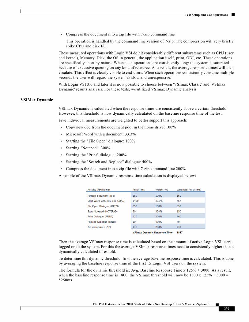
Test Setup and Configurations
• Compress the document into a zip file with 7-zip command line
This operation is handled by the command line version of 7-zip. The compression will very briefly spike CPU and disk I/O.
These measured operations with Login VSI do hit considerably different subsystems such as CPU (user and kernel), Memory, Disk, the OS in general, the application itself, print, GDI, etc. These operations are specifically short by nature. When such operations are consistently long: the system is saturated because of excessive queuing on any kind of resource. As a result, the average response times will then escalate. This effect is clearly visible to end-users. When such operations consistently consume multiple seconds the user will regard the system as slow and unresponsive.
With Login VSI 3.0 and later it is now possible to choose between 'VSImax Classic' and 'VSImax Dynamic' results analysis. For these tests, we utilized VSImax Dynamic analysis.
VSIMax Dynamic
VSImax Dynamic is calculated when the response times are consistently above a certain threshold. However, this threshold is now dynamically calculated on the baseline response time of the test.
Five individual measurements are weighted to better support this approach:
• Copy new doc from the document pool in the home drive: 100%
• Microsoft Word with a document: 33.3%
• Starting the "File Open" dialogue: 100%
• Starting "Notepad": 300%
• Starting the "Print" dialogue: 200%
• Starting the "Search and Replace" dialogue: 400%
• Compress the document into a zip file with 7-zip command line 200%
A sample of the VSImax Dynamic response time calculation is displayed below:
Then the average VSImax response time is calculated based on the amount of active Login VSI users logged on to the system. For this the average VSImax response times need to consistently higher than a dynamically calculated threshold.
To determine this dynamic threshold, first the average baseline response time is calculated. This is done by averaging the baseline response time of the first 15 Login VSI users on the system.
The formula for the dynamic threshold is: Avg. Baseline Response Time x 125% + 3000. As a result, when the baseline response time is 1800, the VSImax threshold will now be 1800 x 125% + 3000 = 5250ms.
239FlexPod Datacenter for 2000 Seats of Citrix XenDesktop 7.1 on VMware vSphere 5.1
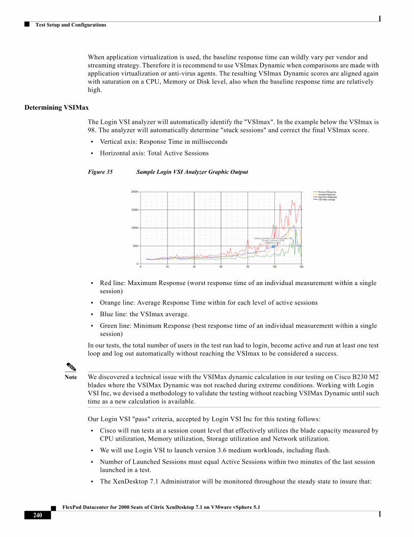
Test Setup and Configurations
When application virtualization is used, the baseline response time can wildly vary per vendor and streaming strategy. Therefore it is recommend to use VSImax Dynamic when comparisons are made with application virtualization or anti-virus agents. The resulting VSImax Dynamic scores are aligned again with saturation on a CPU, Memory or Disk level, also when the baseline response time are relatively high.
Determining VSIMax
The Login VSI analyzer will automatically identify the "VSImax". In the example below the VSImax is 98. The analyzer will automatically determine "stuck sessions" and correct the final VSImax score.
• Vertical axis: Response Time in milliseconds
• Horizontal axis: Total Active Sessions
Figure 35 Sample Login VSI Analyzer Graphic Output
• Red line: Maximum Response (worst response time of an individual measurement within a single session)
• Orange line: Average Response Time within for each level of active sessions
• Blue line: the VSImax average.
• Green line: Minimum Response (best response time of an individual measurement within a single session)
In our tests, the total number of users in the test run had to login, become active and run at least one test loop and log out automatically without reaching the VSImax to be considered a success.
Note We discovered a technical issue with the VSIMax dynamic calculation in our testing on Cisco B230 M2 blades where the VSIMax Dynamic was not reached during extreme conditions. Working with Login VSI Inc, we devised a methodology to validate the testing without reaching VSIMax Dynamic until such time as a new calculation is available.
Our Login VSI "pass" criteria, accepted by Login VSI Inc for this testing follows:
• Cisco will run tests at a session count level that effectively utilizes the blade capacity measured by CPU utilization, Memory utilization, Storage utilization and Network utilization.
• We will use Login VSI to launch version 3.6 medium workloads, including flash.
• Number of Launched Sessions must equal Active Sessions within two minutes of the last session launched in a test.
• The XenDesktop 7.1 Administrator will be monitored throughout the steady state to insure that:
240FlexPod Datacenter for 2000 Seats of Citrix XenDesktop 7.1 on VMware vSphere 5.1
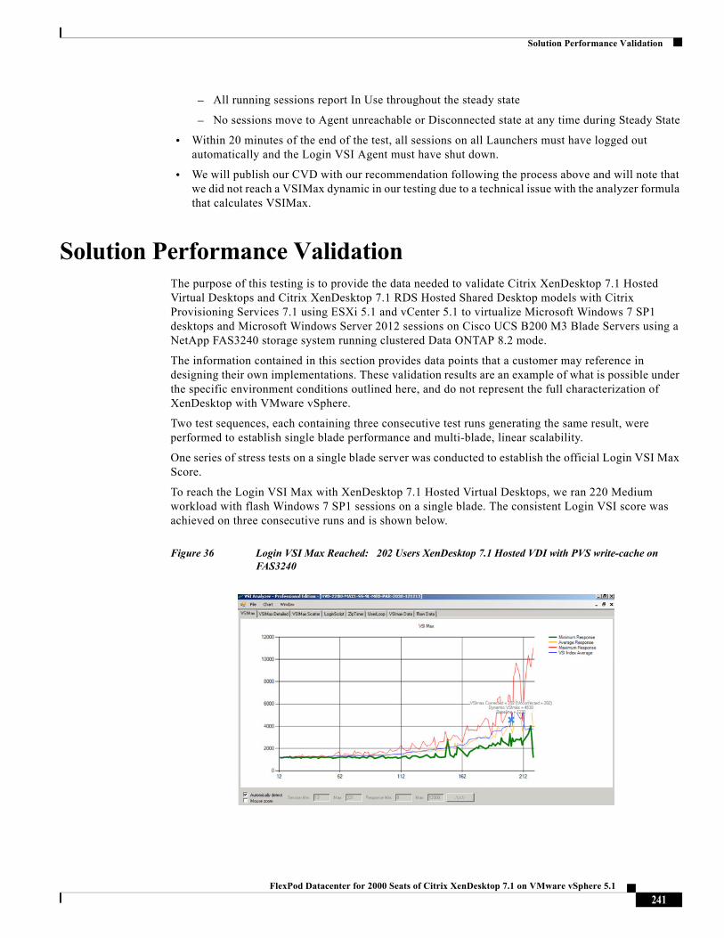
Solution Performance Validation
– All running sessions report In Use throughout the steady state
– No sessions move to Agent unreachable or Disconnected state at any time during Steady State
• Within 20 minutes of the end of the test, all sessions on all Launchers must have logged out automatically and the Login VSI Agent must have shut down.
• We will publish our CVD with our recommendation following the process above and will note that we did not reach a VSIMax dynamic in our testing due to a technical issue with the analyzer formula that calculates VSIMax.
Solution Performance ValidationThe purpose of this testing is to provide the data needed to validate Citrix XenDesktop 7.1 Hosted Virtual Desktops and Citrix XenDesktop 7.1 RDS Hosted Shared Desktop models with Citrix Provisioning Services 7.1 using ESXi 5.1 and vCenter 5.1 to virtualize Microsoft Windows 7 SP1 desktops and Microsoft Windows Server 2012 sessions on Cisco UCS B200 M3 Blade Servers using a NetApp FAS3240 storage system running clustered Data ONTAP 8.2 mode.
The information contained in this section provides data points that a customer may reference in designing their own implementations. These validation results are an example of what is possible under the specific environment conditions outlined here, and do not represent the full characterization of XenDesktop with VMware vSphere.
Two test sequences, each containing three consecutive test runs generating the same result, were performed to establish single blade performance and multi-blade, linear scalability.
One series of stress tests on a single blade server was conducted to establish the official Login VSI Max Score.
To reach the Login VSI Max with XenDesktop 7.1 Hosted Virtual Desktops, we ran 220 Medium workload with flash Windows 7 SP1 sessions on a single blade. The consistent Login VSI score was achieved on three consecutive runs and is shown below.
Figure 36 Login VSI Max Reached: 202 Users XenDesktop 7.1 Hosted VDI with PVS write-cache on FAS3240
241FlexPod Datacenter for 2000 Seats of Citrix XenDesktop 7.1 on VMware vSphere 5.1
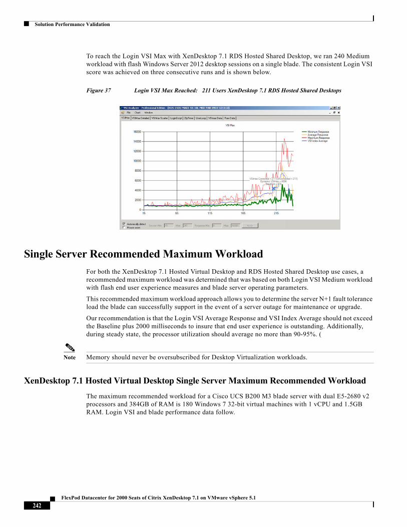
Solution Performance Validation
To reach the Login VSI Max with XenDesktop 7.1 RDS Hosted Shared Desktop, we ran 240 Medium workload with flash Windows Server 2012 desktop sessions on a single blade. The consistent Login VSI score was achieved on three consecutive runs and is shown below.
Figure 37 Login VSI Max Reached: 211 Users XenDesktop 7.1 RDS Hosted Shared Desktops
Single Server Recommended Maximum Workload
For both the XenDesktop 7.1 Hosted Virtual Desktop and RDS Hosted Shared Desktop use cases, a recommended maximum workload was determined that was based on both Login VSI Medium workload with flash end user experience measures and blade server operating parameters.
This recommended maximum workload approach allows you to determine the server N+1 fault tolerance load the blade can successfully support in the event of a server outage for maintenance or upgrade.
Our recommendation is that the Login VSI Average Response and VSI Index Average should not exceed the Baseline plus 2000 milliseconds to insure that end user experience is outstanding. Additionally, during steady state, the processor utilization should average no more than 90-95%. (
Note Memory should never be oversubscribed for Desktop Virtualization workloads.
XenDesktop 7.1 Hosted Virtual Desktop Single Server Maximum Recommended Workload
The maximum recommended workload for a Cisco UCS B200 M3 blade server with dual E5-2680 v2 processors and 384GB of RAM is 180 Windows 7 32-bit virtual machines with 1 vCPU and 1.5GB RAM. Login VSI and blade performance data follow.
242FlexPod Datacenter for 2000 Seats of Citrix XenDesktop 7.1 on VMware vSphere 5.1
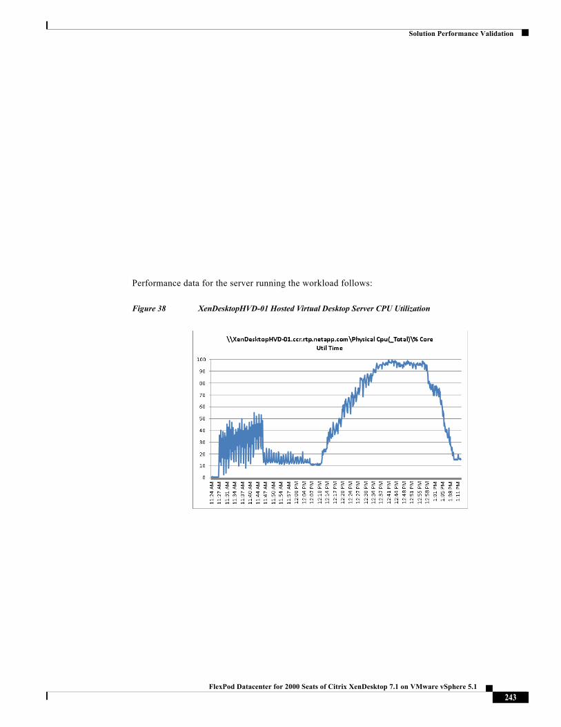
Solution Performance Validation
Performance data for the server running the workload follows:
Figure 38 XenDesktopHVD-01 Hosted Virtual Desktop Server CPU Utilization
243FlexPod Datacenter for 2000 Seats of Citrix XenDesktop 7.1 on VMware vSphere 5.1
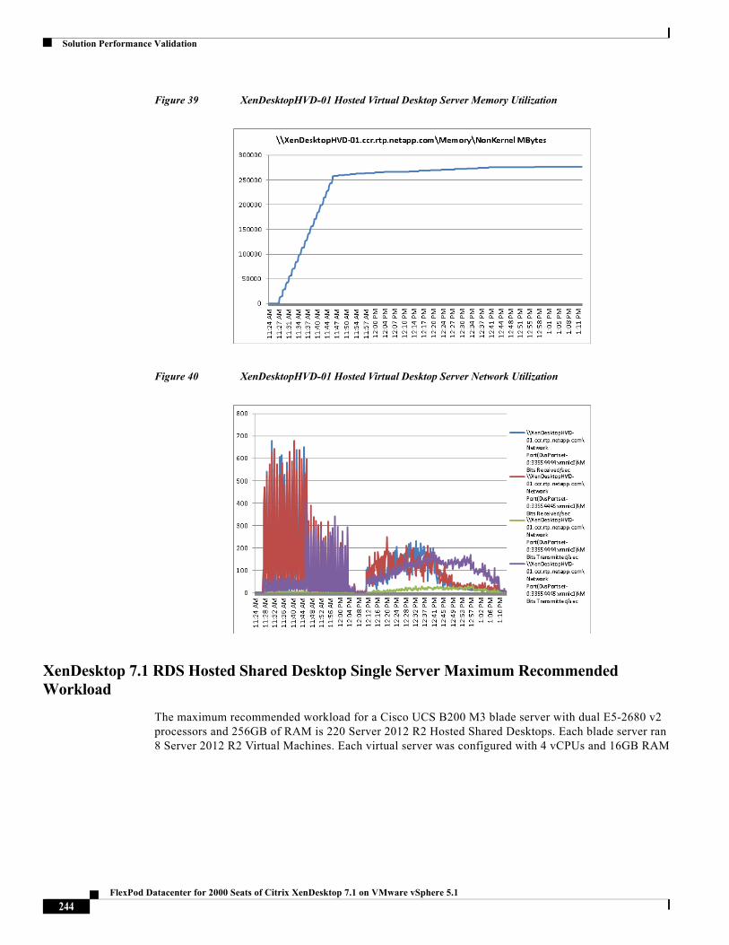
Solution Performance Validation
Figure 39 XenDesktopHVD-01 Hosted Virtual Desktop Server Memory Utilization
Figure 40 XenDesktopHVD-01 Hosted Virtual Desktop Server Network Utilization
XenDesktop 7.1 RDS Hosted Shared Desktop Single Server Maximum Recommended Workload
The maximum recommended workload for a Cisco UCS B200 M3 blade server with dual E5-2680 v2 processors and 256GB of RAM is 220 Server 2012 R2 Hosted Shared Desktops. Each blade server ran 8 Server 2012 R2 Virtual Machines. Each virtual server was configured with 4 vCPUs and 16GB RAM
244FlexPod Datacenter for 2000 Seats of Citrix XenDesktop 7.1 on VMware vSphere 5.1
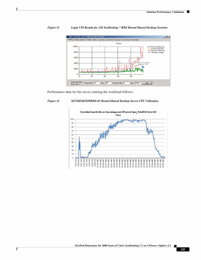
Solution Performance Validation
Figure 41 Login VSI Results for 220 XenDesktop 7 RDS Hosted Shared Desktop Sessions
Performance data for the server running the workload follows:
Figure 42 XENDESKTOPRDS-01 Hosted Shared Desktop Server CPU Utilization
245FlexPod Datacenter for 2000 Seats of Citrix XenDesktop 7.1 on VMware vSphere 5.1
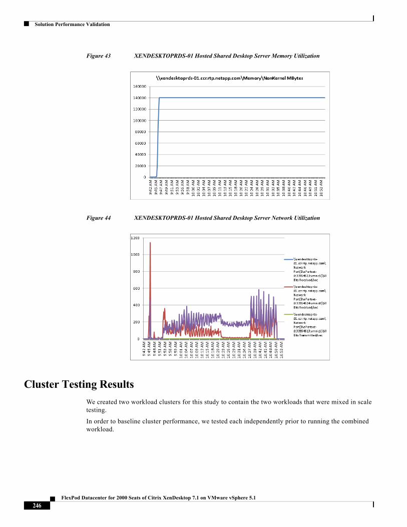
Solution Performance Validation
Figure 43 XENDESKTOPRDS-01 Hosted Shared Desktop Server Memory Utilization
Figure 44 XENDESKTOPRDS-01 Hosted Shared Desktop Server Network Utilization
Cluster Testing Results
We created two workload clusters for this study to contain the two workloads that were mixed in scale testing.
In order to baseline cluster performance, we tested each independently prior to running the combined workload.
246FlexPod Datacenter for 2000 Seats of Citrix XenDesktop 7.1 on VMware vSphere 5.1
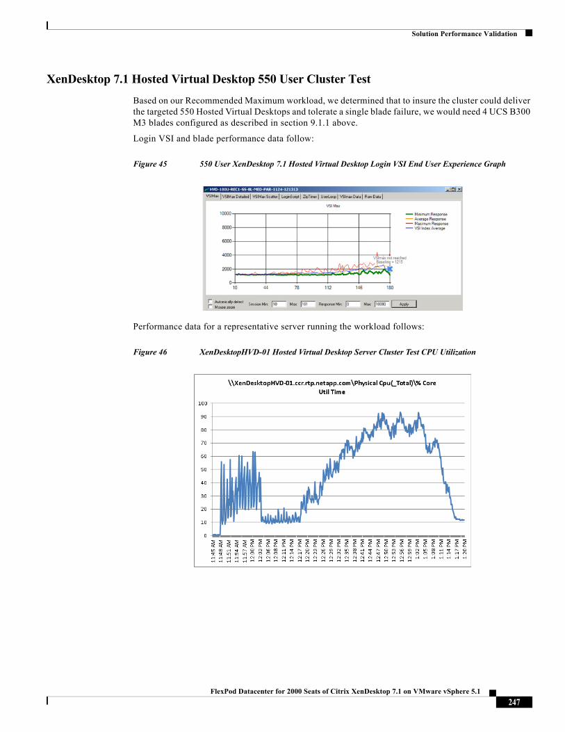
Solution Performance Validation
XenDesktop 7.1 Hosted Virtual Desktop 550 User Cluster Test
Based on our Recommended Maximum workload, we determined that to insure the cluster could deliver the targeted 550 Hosted Virtual Desktops and tolerate a single blade failure, we would need 4 UCS B300 M3 blades configured as described in section 9.1.1 above.
Login VSI and blade performance data follow:
Figure 45 550 User XenDesktop 7.1 Hosted Virtual Desktop Login VSI End User Experience Graph
Performance data for a representative server running the workload follows:
Figure 46 XenDesktopHVD-01 Hosted Virtual Desktop Server Cluster Test CPU Utilization
247FlexPod Datacenter for 2000 Seats of Citrix XenDesktop 7.1 on VMware vSphere 5.1
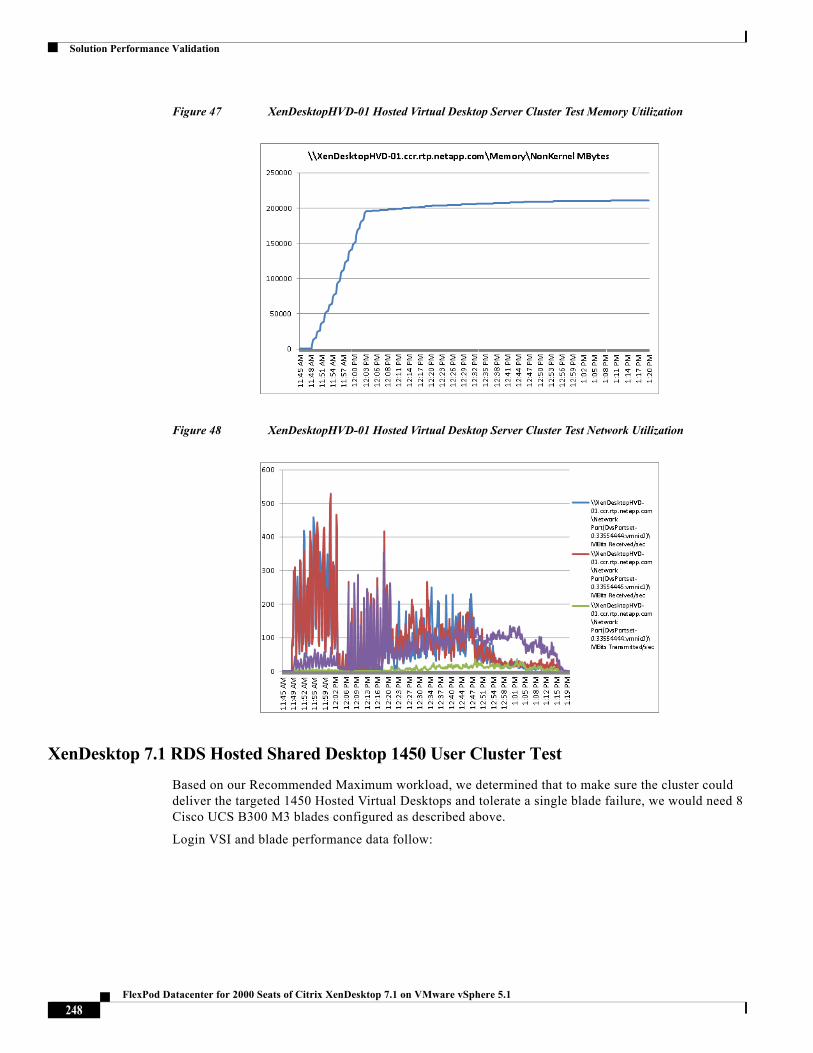
Solution Performance Validation
Figure 47 XenDesktopHVD-01 Hosted Virtual Desktop Server Cluster Test Memory Utilization
Figure 48 XenDesktopHVD-01 Hosted Virtual Desktop Server Cluster Test Network Utilization
XenDesktop 7.1 RDS Hosted Shared Desktop 1450 User Cluster Test
Based on our Recommended Maximum workload, we determined that to make sure the cluster could deliver the targeted 1450 Hosted Virtual Desktops and tolerate a single blade failure, we would need 8 Cisco UCS B300 M3 blades configured as described above.
Login VSI and blade performance data follow:
248FlexPod Datacenter for 2000 Seats of Citrix XenDesktop 7.1 on VMware vSphere 5.1
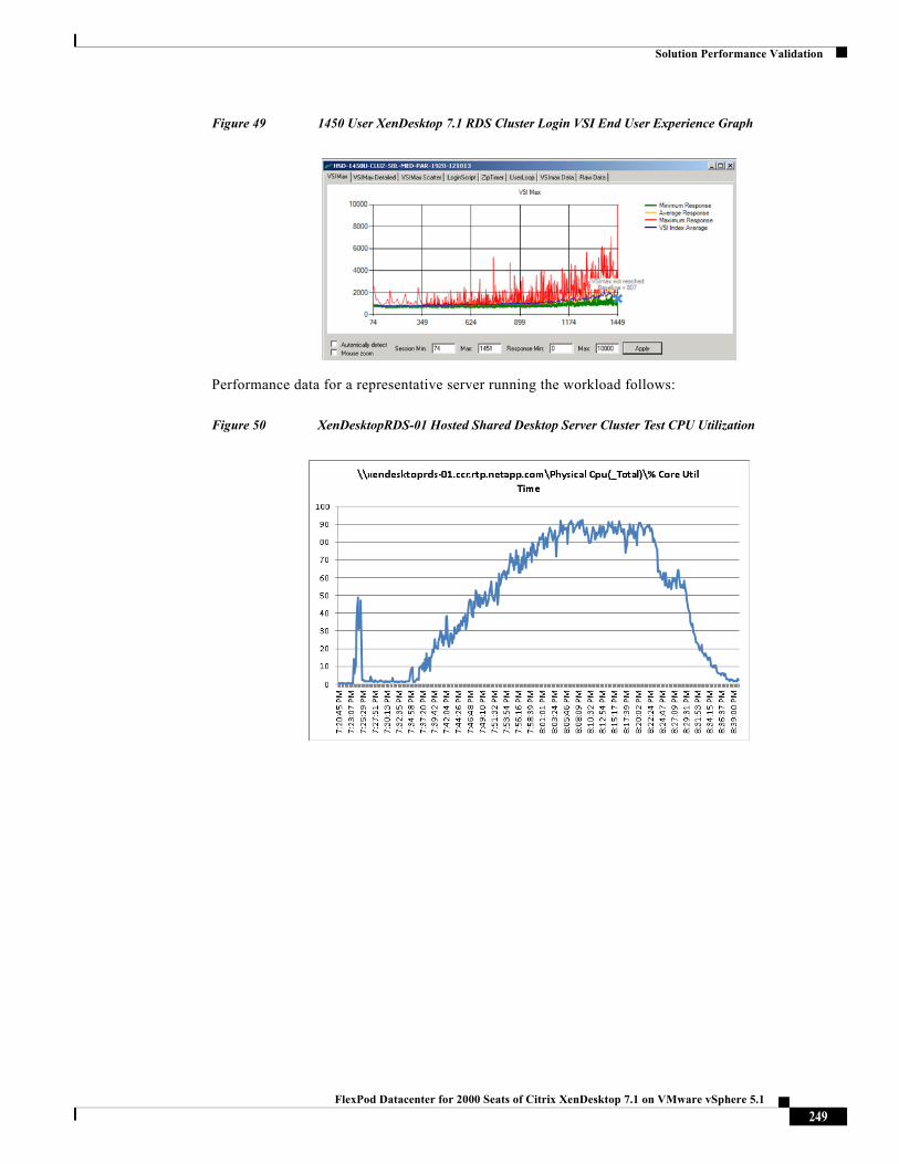
Solution Performance Validation
Figure 49 1450 User XenDesktop 7.1 RDS Cluster Login VSI End User Experience Graph
Performance data for a representative server running the workload follows:
Figure 50 XenDesktopRDS-01 Hosted Shared Desktop Server Cluster Test CPU Utilization
249FlexPod Datacenter for 2000 Seats of Citrix XenDesktop 7.1 on VMware vSphere 5.1
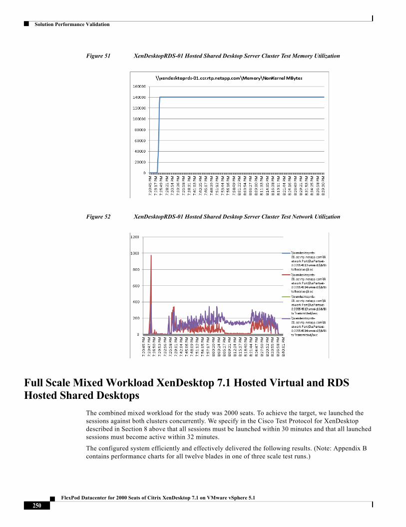
Solution Performance Validation
Figure 51 XenDesktopRDS-01 Hosted Shared Desktop Server Cluster Test Memory Utilization
Figure 52 XenDesktopRDS-01 Hosted Shared Desktop Server Cluster Test Network Utilization
Full Scale Mixed Workload XenDesktop 7.1 Hosted Virtual and RDS Hosted Shared Desktops
The combined mixed workload for the study was 2000 seats. To achieve the target, we launched the sessions against both clusters concurrently. We specify in the Cisco Test Protocol for XenDesktop described in Section 8 above that all sessions must be launched within 30 minutes and that all launched sessions must become active within 32 minutes.
The configured system efficiently and effectively delivered the following results. (Note: Appendix B contains performance charts for all twelve blades in one of three scale test runs.)
250FlexPod Datacenter for 2000 Seats of Citrix XenDesktop 7.1 on VMware vSphere 5.1
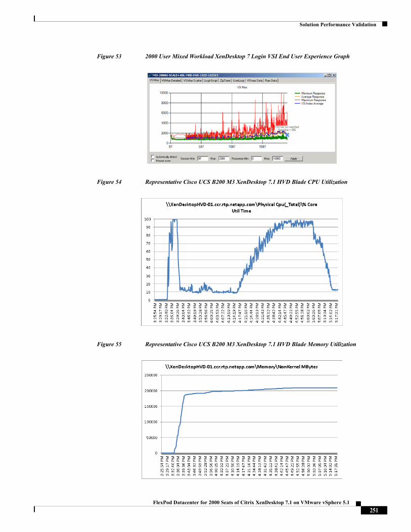
Solution Performance Validation
Figure 53 2000 User Mixed Workload XenDesktop 7 Login VSI End User Experience Graph
Figure 54 Representative Cisco UCS B200 M3 XenDesktop 7.1 HVD Blade CPU Utilization
Figure 55 Representative Cisco UCS B200 M3 XenDesktop 7.1 HVD Blade Memory Utilization
251FlexPod Datacenter for 2000 Seats of Citrix XenDesktop 7.1 on VMware vSphere 5.1
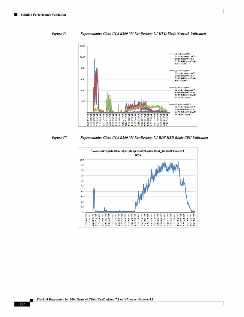
Solution Performance Validation
Figure 56 Representative Cisco UCS B200 M3 XenDesktop 7.1 HVD Blade Network Utilization
Figure 57 Representative Cisco UCS B200 M3 XenDesktop 7.1 RDS HSD Blade CPU Utilization
252FlexPod Datacenter for 2000 Seats of Citrix XenDesktop 7.1 on VMware vSphere 5.1
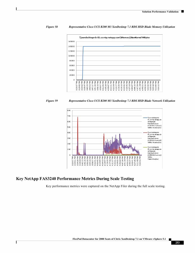
Solution Performance Validation
Figure 58 Representative Cisco UCS B200 M3 XenDesktop 7.1 RDS HSD Blade Memory Utilization
Figure 59 Representative Cisco UCS B200 M3 XenDesktop 7.1 RDS HSD Blade Network Utilization
Key NetApp FAS3240 Performance Metrics During Scale Testing
Key performance metrics were captured on the NetApp Filer during the full scale testing.
253FlexPod Datacenter for 2000 Seats of Citrix XenDesktop 7.1 on VMware vSphere 5.1
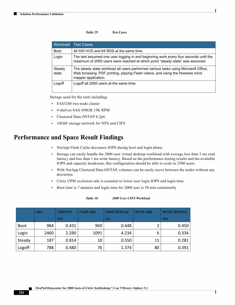
Solution Performance Validation
Table 29 Test Cases
Storage used for the tests including:
• FAS3240 two-node cluster
• 4 shelves SAS 450GB 15K RPM
• Clustered Data ONTAP 8.2p4.
• 10GbE storage network for NFS and CIFS
Performance and Space Result Findings
• NetApp Flash Cache decreases IOPS during boot and login phase
• Storage can easily handle the 2000 user virtual desktop workload with average less than 3 ms read latency and less than 1 ms write latency. Based on the performance testing results and the available IOPS and capacity headroom, this configuration should be able to scale to 2500 users.
• With NetApp Clustered Data ONTAP, volumes can be easily move between the nodes without any downtime.
• Citrix UPM exclusion rule is essential to lower user login IOPS and login time
• Boot time is 7 minutes and login time for 2000 user is 30 min consistently
Table 30 2000 User CIFS Workload
Workload Test Cases
Boot All 550 HVD and 64 RDS at the same time.
Login The test assumed one user logging in and beginning work every four seconds until the maximum of 2000 users were reached at which point “steady state” was assumed.
Steady state
The steady state workload all users performed various tasks using Microsoft Office, Web browsing, PDF printing, playing Flash videos, and using the freeware mind mapper application.
Logoff Logoff all 2000 users at the same time.
ops Latency
ms
read ops read latency
us
write ops write latency
ms
Boot 984 0.431 969 0.448 2 0.450
Login 2460 2.290 1091 4.234 6 0.334
Steady 187 0.814 10 0.550 11 0.281
Logoff 788 0.480 76 1.374 80 0.391
254FlexPod Datacenter for 2000 Seats of Citrix XenDesktop 7.1 on VMware vSphere 5.1
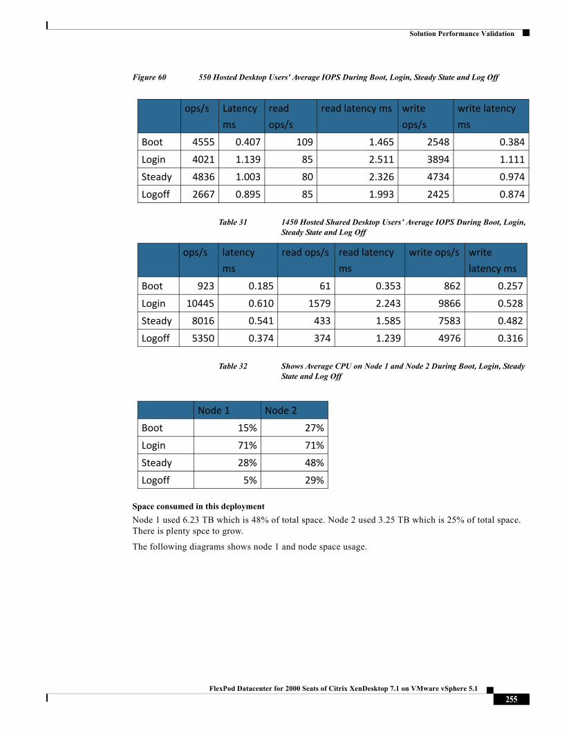
Solution Performance Validation
Figure 60 550 Hosted Desktop Users' Average IOPS During Boot, Login, Steady State and Log Off
Table 31 1450 Hosted Shared Desktop Users’ Average IOPS During Boot, Login, Steady State and Log Off
Table 32 Shows Average CPU on Node 1 and Node 2 During Boot, Login, Steady State and Log Off
Space consumed in this deployment
Node 1 used 6.23 TB which is 48% of total space. Node 2 used 3.25 TB which is 25% of total space. There is plenty spce to grow.
The following diagrams shows node 1 and node space usage.
ops/s Latency
ms
read
ops/s
read latency ms write
ops/s
write latency
ms
Boot 4555 0.407 109 1.465 2548 0.384
Login 4021 1.139 85 2.511 3894 1.111
Steady 4836 1.003 80 2.326 4734 0.974
Logoff 2667 0.895 85 1.993 2425 0.874
ops/s latency
ms
read ops/s read latency
ms
write ops/s write
latency ms
Boot 923 0.185 61 0.353 862 0.257
Login 10445 0.610 1579 2.243 9866 0.528
Steady 8016 0.541 433 1.585 7583 0.482
Logoff 5350 0.374 374 1.239 4976 0.316
Node 1 Node 2
Boot 15% 27%
Login 71% 71%
Steady 28% 48%
Logoff 5% 29%
255FlexPod Datacenter for 2000 Seats of Citrix XenDesktop 7.1 on VMware vSphere 5.1
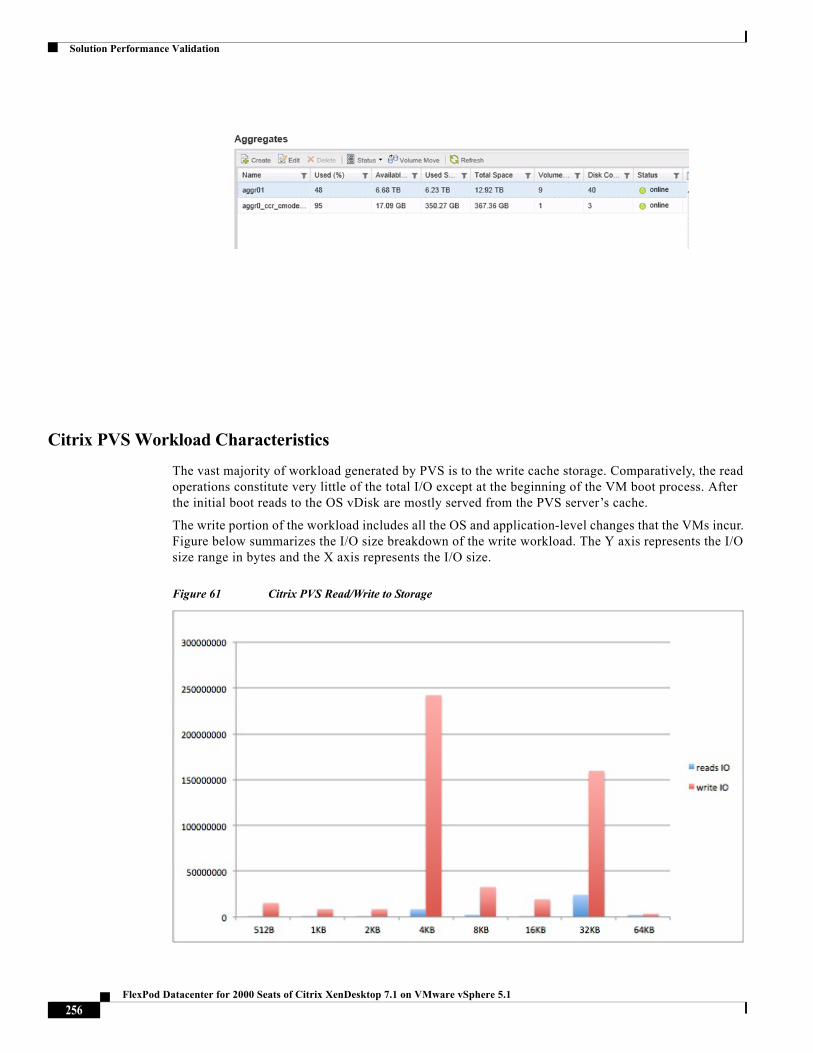
Solution Performance Validation
Citrix PVS Workload Characteristics
The vast majority of workload generated by PVS is to the write cache storage. Comparatively, the read operations constitute very little of the total I/O except at the beginning of the VM boot process. After the initial boot reads to the OS vDisk are mostly served from the PVS server’s cache.
The write portion of the workload includes all the OS and application-level changes that the VMs incur. Figure below summarizes the I/O size breakdown of the write workload. The Y axis represents the I/O size range in bytes and the X axis represents the I/O size.
Figure 61 Citrix PVS Read/Write to Storage
256FlexPod Datacenter for 2000 Seats of Citrix XenDesktop 7.1 on VMware vSphere 5.1
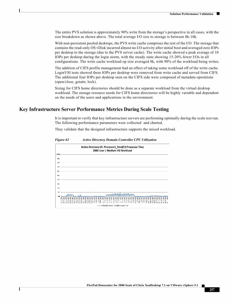
Solution Performance Validation
The entire PVS solution is approximately 90% write from the storage’s perspective in all cases, with the size breakdown as shown above. The total average I/O size to storage is between 8k-10k.
With non-persistent pooled desktops, the PVS write cache comprises the rest of the I/O. The storage that contains the read-only OS vDisk incurred almost no I/O activity after initial boot and averaged zero IOPs per desktop to the storage (due to the PVS server cache). The write cache showed a peak average of 10 IOPs per desktop during the login storm, with the steady state showing 15-20% fewer I/Os in all configurations. The write cache workload op size averaged 8k, with 90% of the workload being writes.
The addition of CIFS profile management had an effect of taking some workload off of the write cache. LoginVSI tests showed three IOPs per desktop were removed from write cache and served from CIFS. The additional four IOPs per desktop seen on the CIFS side were composed of metadata operations (open/close, getattr, lock).
Sizing for CIFS home directories should be done as a separate workload from the virtual desktop workload. The storage resource needs for CIFS home directories will be highly variable and dependent on the needs of the users and applications in the environment.
Key Infrastructure Server Performance Metrics During Scale Testing
It is important to verify that key infrastructure servers are performing optimally during the scale test run. The following performance parameters were collected and charted.
They validate that the designed infrastructure supports the mixed workload.
Figure 62 Active Directory Domain Controller CPU Utilization
257FlexPod Datacenter for 2000 Seats of Citrix XenDesktop 7.1 on VMware vSphere 5.1
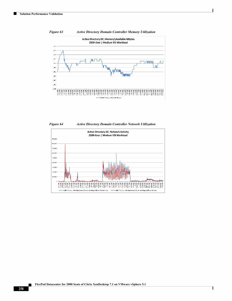
Solution Performance Validation
Figure 63 Active Directory Domain Controller Memory Utilization
Figure 64 Active Directory Domain Controller Network Utilization
258FlexPod Datacenter for 2000 Seats of Citrix XenDesktop 7.1 on VMware vSphere 5.1
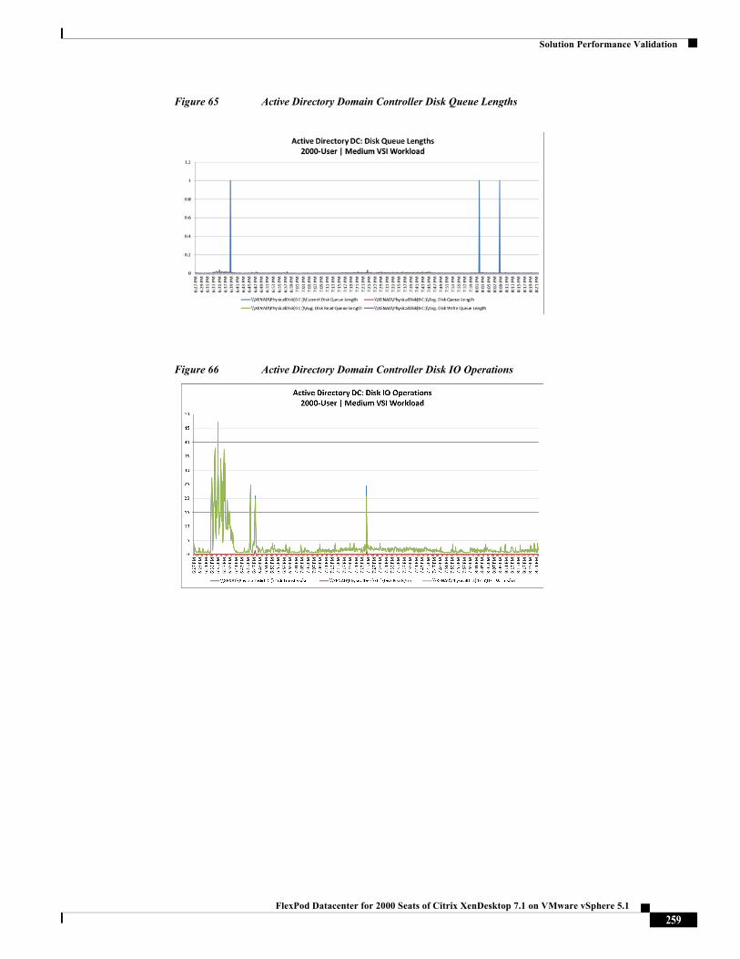
Solution Performance Validation
Figure 65 Active Directory Domain Controller Disk Queue Lengths
Figure 66 Active Directory Domain Controller Disk IO Operations
259FlexPod Datacenter for 2000 Seats of Citrix XenDesktop 7.1 on VMware vSphere 5.1
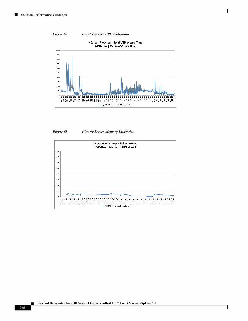
Solution Performance Validation
Figure 67 vCenter Server CPU Utilization
Figure 68 vCenter Server Memory Utilization
260FlexPod Datacenter for 2000 Seats of Citrix XenDesktop 7.1 on VMware vSphere 5.1
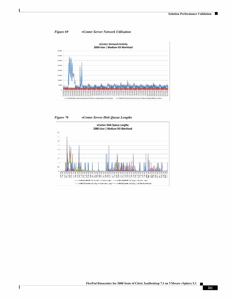
Solution Performance Validation
Figure 69 vCenter Server Network Utilization
Figure 70 vCenter Server Disk Queue Lengths
261FlexPod Datacenter for 2000 Seats of Citrix XenDesktop 7.1 on VMware vSphere 5.1
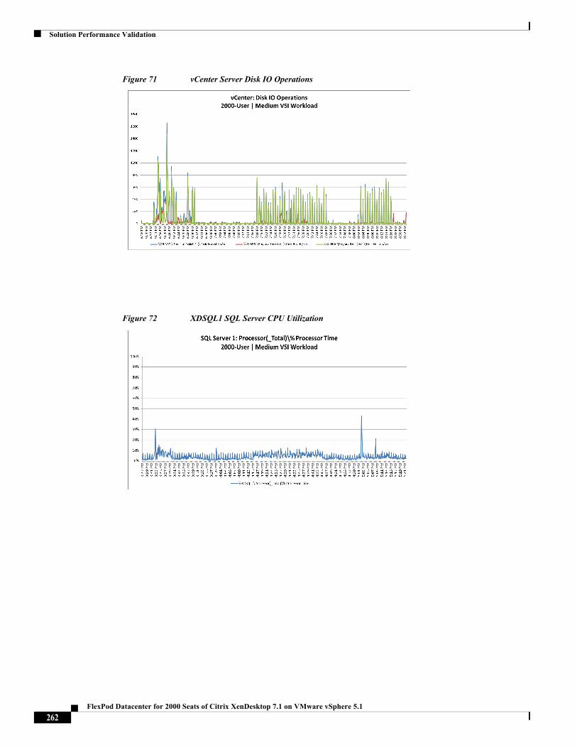
Solution Performance Validation
Figure 71 vCenter Server Disk IO Operations
Figure 72 XDSQL1 SQL Server CPU Utilization
262FlexPod Datacenter for 2000 Seats of Citrix XenDesktop 7.1 on VMware vSphere 5.1
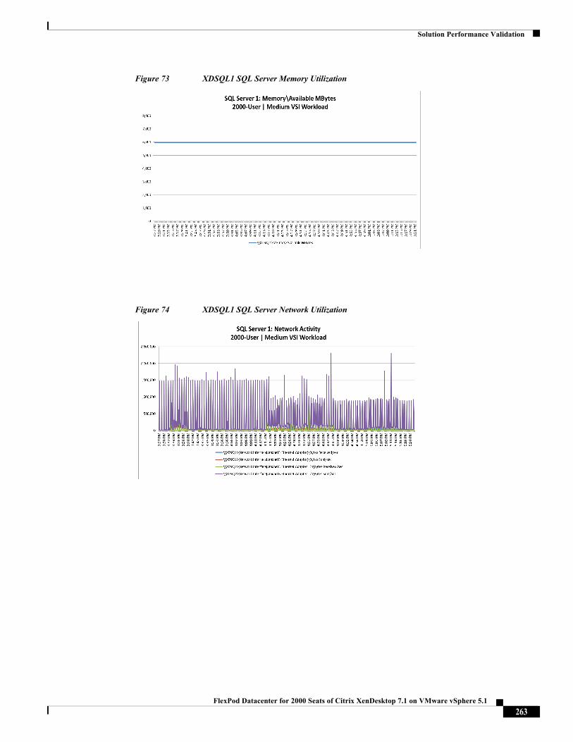
Solution Performance Validation
Figure 73 XDSQL1 SQL Server Memory Utilization
Figure 74 XDSQL1 SQL Server Network Utilization
263FlexPod Datacenter for 2000 Seats of Citrix XenDesktop 7.1 on VMware vSphere 5.1
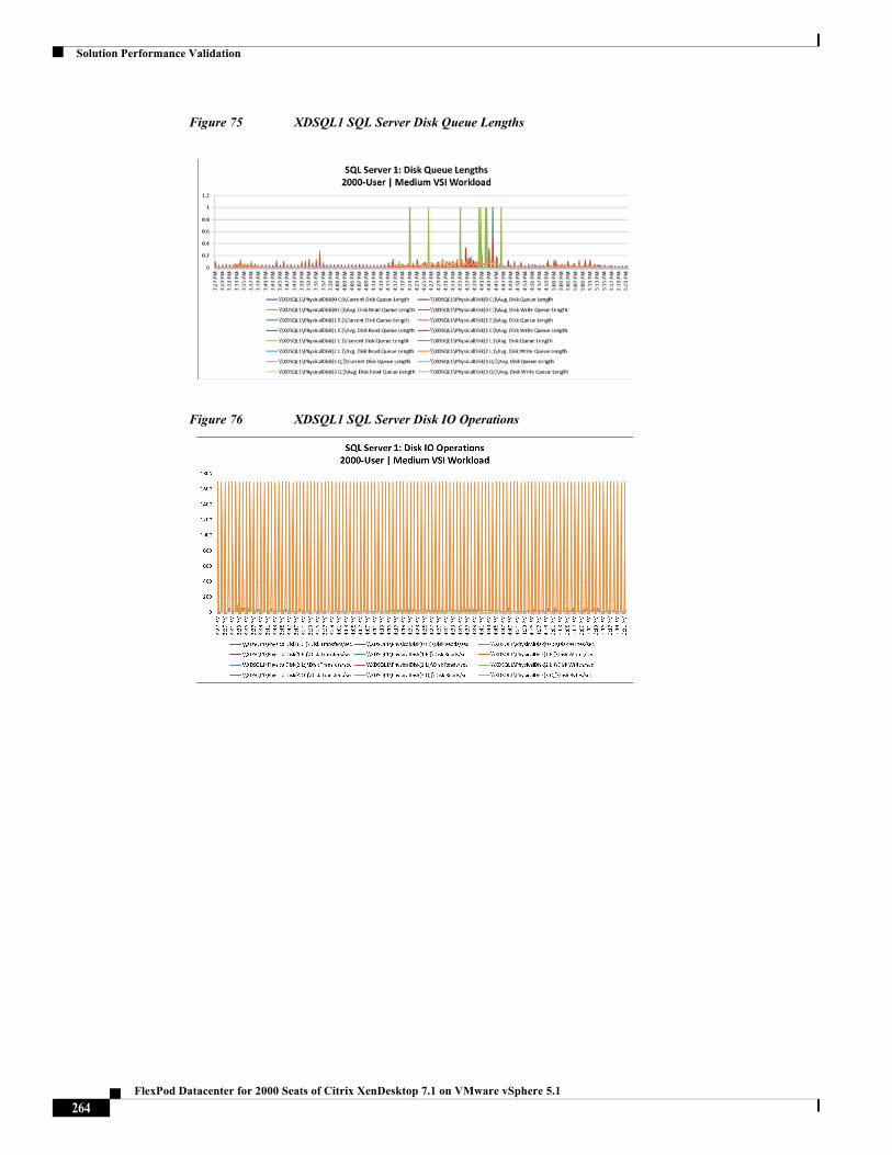
Solution Performance Validation
Figure 75 XDSQL1 SQL Server Disk Queue Lengths
Figure 76 XDSQL1 SQL Server Disk IO Operations
264FlexPod Datacenter for 2000 Seats of Citrix XenDesktop 7.1 on VMware vSphere 5.1
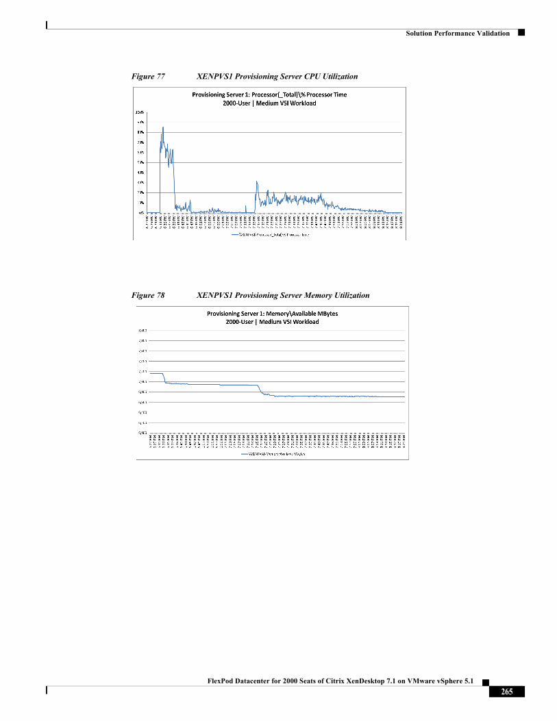
Solution Performance Validation
Figure 77 XENPVS1 Provisioning Server CPU Utilization
Figure 78 XENPVS1 Provisioning Server Memory Utilization
265FlexPod Datacenter for 2000 Seats of Citrix XenDesktop 7.1 on VMware vSphere 5.1
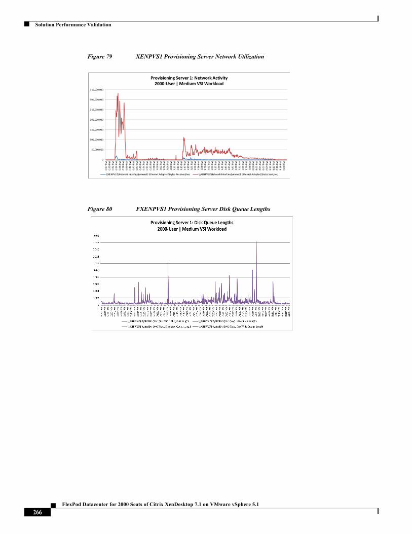
Solution Performance Validation
Figure 79 XENPVS1 Provisioning Server Network Utilization
Figure 80 FXENPVS1 Provisioning Server Disk Queue Lengths
266FlexPod Datacenter for 2000 Seats of Citrix XenDesktop 7.1 on VMware vSphere 5.1
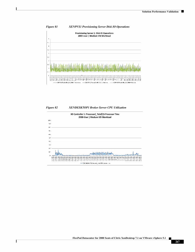
Solution Performance Validation
Figure 81 XENPVS1 Provisioning Server Disk IO Operations
Figure 82 XENDESKTOP1 Broker Server CPU Utilization
267FlexPod Datacenter for 2000 Seats of Citrix XenDesktop 7.1 on VMware vSphere 5.1
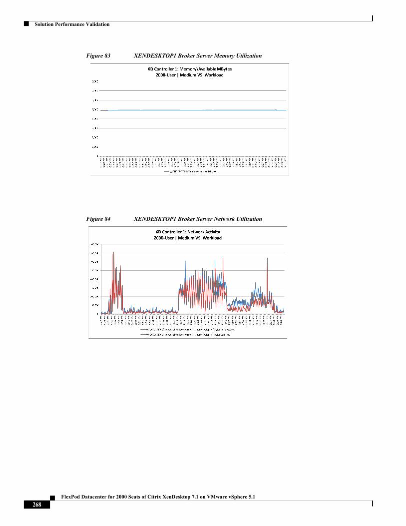
Solution Performance Validation
Figure 83 XENDESKTOP1 Broker Server Memory Utilization
Figure 84 XENDESKTOP1 Broker Server Network Utilization
268FlexPod Datacenter for 2000 Seats of Citrix XenDesktop 7.1 on VMware vSphere 5.1
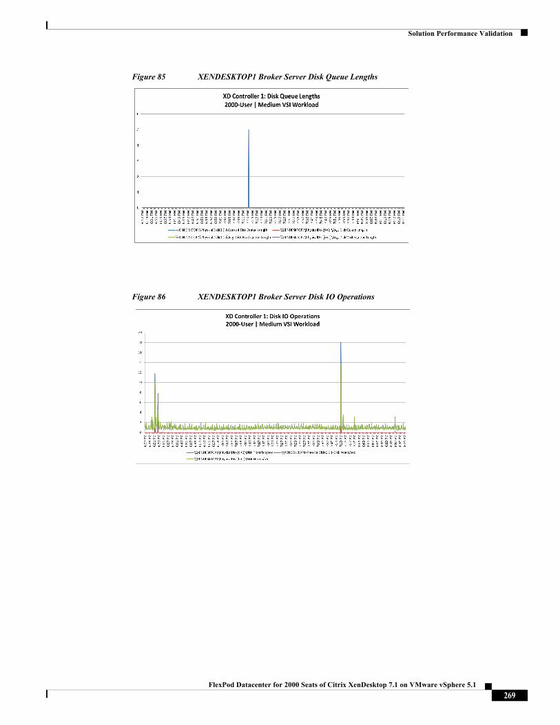
Solution Performance Validation
Figure 85 XENDESKTOP1 Broker Server Disk Queue Lengths
Figure 86 XENDESKTOP1 Broker Server Disk IO Operations
269FlexPod Datacenter for 2000 Seats of Citrix XenDesktop 7.1 on VMware vSphere 5.1
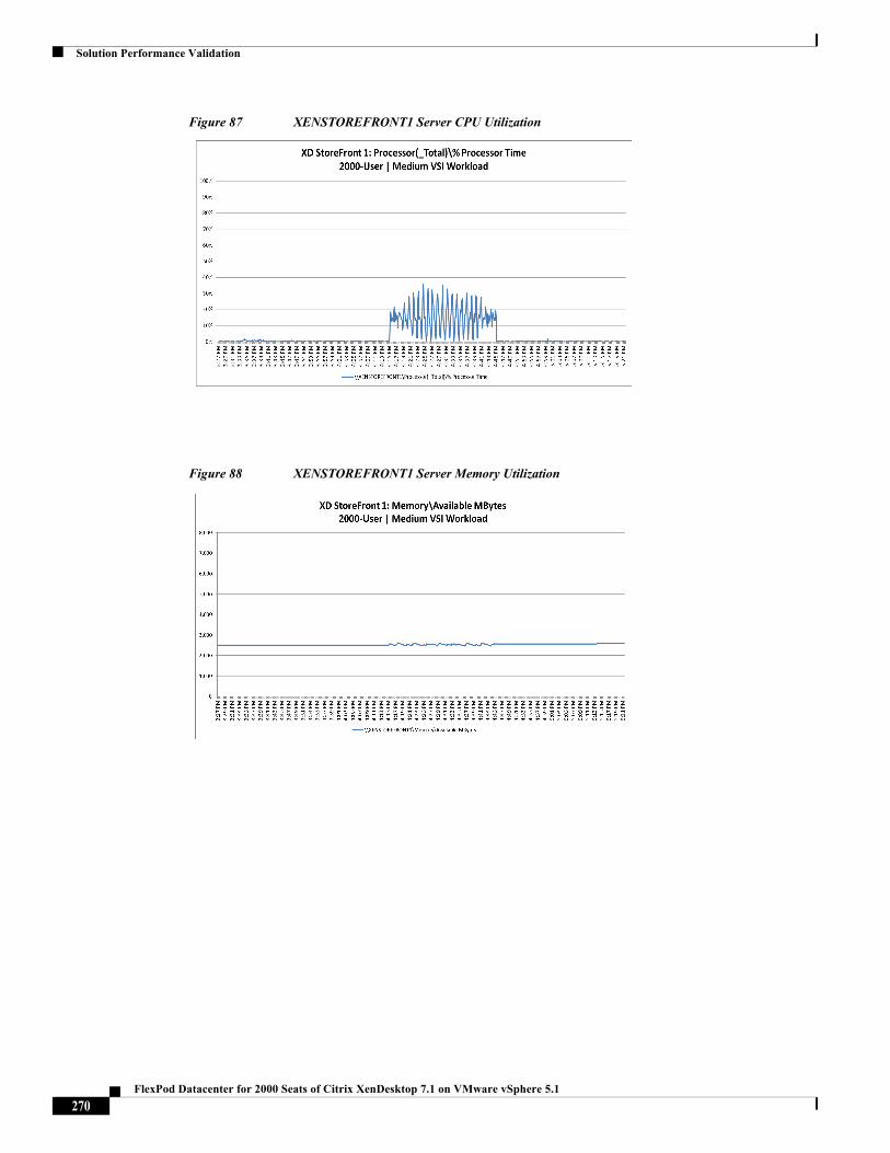
Solution Performance Validation
Figure 87 XENSTOREFRONT1 Server CPU Utilization
Figure 88 XENSTOREFRONT1 Server Memory Utilization
270FlexPod Datacenter for 2000 Seats of Citrix XenDesktop 7.1 on VMware vSphere 5.1
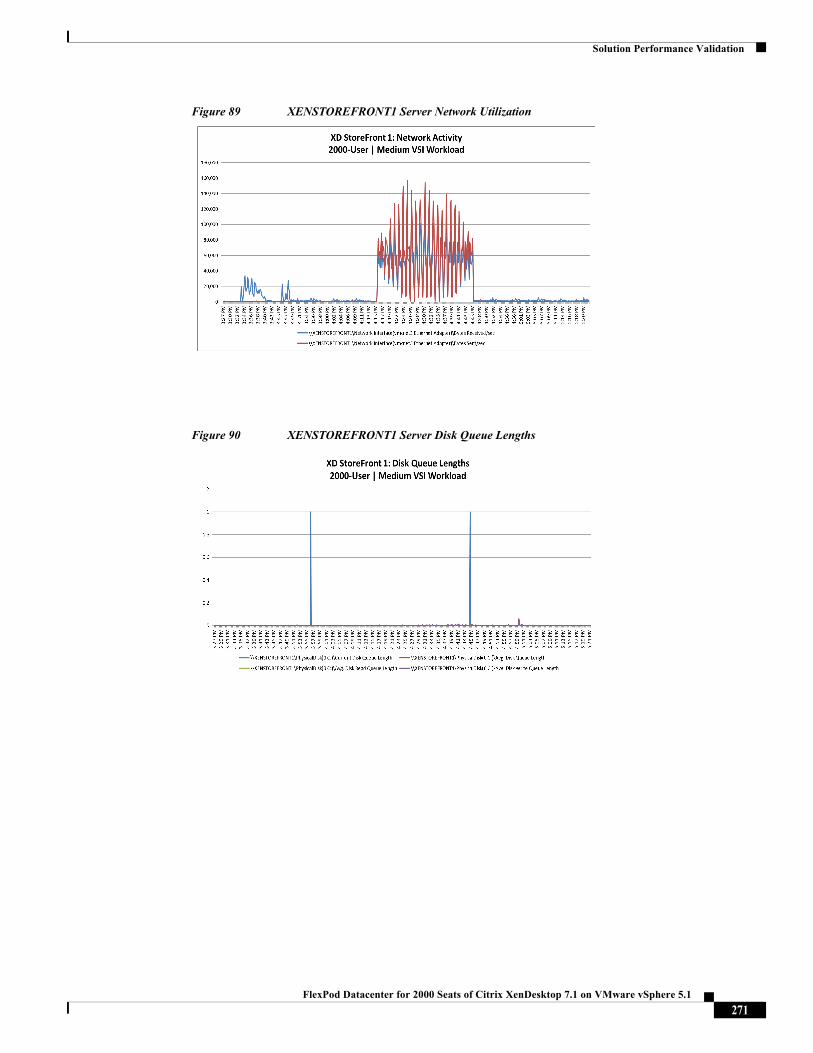
Solution Performance Validation
Figure 89 XENSTOREFRONT1 Server Network Utilization
Figure 90 XENSTOREFRONT1 Server Disk Queue Lengths
271FlexPod Datacenter for 2000 Seats of Citrix XenDesktop 7.1 on VMware vSphere 5.1
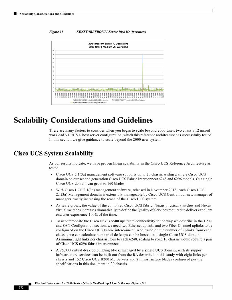
Scalability Considerations and Guidelines
Figure 91 XENSTOREFRONT1 Server Disk IO Operations
Scalability Considerations and GuidelinesThere are many factors to consider when you begin to scale beyond 2000 User, two chassis 12 mixed workload VDI/HVD host server configuration, which this reference architecture has successfully tested. In this section we give guidance to scale beyond the 2000 user system.
Cisco UCS System Scalability
As our results indicate, we have proven linear scalability in the Cisco UCS Reference Architecture as tested.
• Cisco UCS 2.1(3a) management software supports up to 20 chassis within a single Cisco UCS domain on our second generation Cisco UCS Fabric Interconnect 6248 and 6296 models. Our single Cisco UCS domain can grow to 160 blades.
• With Cisco UCS 2.1(3a) management software, released in November 2013, each Cisco UCS 2.1(3a) Management domain is extensibly manageable by Cisco UCS Central, our new manager of managers, vastly increasing the reach of the Cisco UCS system.
• As scale grows, the value of the combined Cisco UCS fabric, Nexus physical switches and Nexus virtual switches increases dramatically to define the Quality of Services required to deliver excellent end user experience 100% of the time.
• To accommodate the Cisco Nexus 5500 upstream connectivity in the way we describe in the LAN and SAN Configuration section, we need two Ethernet uplinks and two Fiber Channel uplinks to be configured on the Cisco UCS Fabric interconnect. And based on the number of uplinks from each chassis, we can calculate number of desktops can be hosted in a single Cisco UCS domain. Assuming eight links per chassis, four to each 6248, scaling beyond 10 chassis would require a pair of Cisco UCS 6296 fabric interconnects.
• A 25,000 virtual desktop building block, managed by a single UCS domain, with its support infrastructure services can be built out from the RA described in this study with eight links per chassis and 152 Cisco UCS B200 M3 Servers and 8 infrastructure blades configured per the specifications in this document in 20 chassis.
272FlexPod Datacenter for 2000 Seats of Citrix XenDesktop 7.1 on VMware vSphere 5.1
Scalability Considerations and Guidelines
The backend storage has to be scaled accordingly, based on the IOP considerations as described in the NetApp scaling section. Please refer the NetApp section that follows this one for scalability guidelines.
Scalability of Citrix XenDesktop 7.1 Configuration
XenDesktop environments can scale to large numbers. When implementing Citrix XenDesktop, consider the following in scaling the number of hosted shared and hosted virtual desktops:
• Types of storage in your environment
• Types of desktops that will be deployed
• Data protection requirements
• For Citrix Provisioning Server pooled desktops, the write cache sizing and placement
These and other various aspects of scalability considerations are described in greater detail in "XenDesktop - Modular Reference Architecture" document and should be a part of any XenDesktop design.
When designing and deploying this CVD environment, best practices were followed including the following:
• Citrix recommends using N+1 schema for virtualization host servers to accommodate resiliency. In all Reference Architectures (such as this CVD), this recommendation is applied to all host servers.
• All Provisioning Server Network Adapters are configured to have a static IP and management.
• We used the XenDesktop Setup Wizard in PVS. Wizard does an excellent job of creating the desktops automatically and it's possible to run multiple instances of the wizard, provided the deployed desktops are placed in different catalogs and have different naming conventions. To use the PVS XenDesktop Setup Wizard, at a minimum you need to install the Provisioning Server, the XenDesktop Controller, and configure hosts, as well as create VM templates on all datastores where desktops will be deployed.
NetApp FAS Storage Guidelines for Mixed Desktops Virtualization Workload
Storage sizing has three steps:
1. Gathering solution requirements.
2. Estimating storage capacity and performance.
3. Obtaining recommendations for storage configuration.
Solution Assessment
Assessment is an important first step. Liquidware Labs Stratusphere FIT and Lakeside VDI Assessment are recommended to collect network, server, and storage requirements. NetApp has contracted with Liquidware Labs to provide free licenses to NetApp employees and channel partners. For information on how to obtain software and licenses, refer to this FAQ. Liquidware Labs also provides a storage template fits NetApp system performance modeler. For guidelines on how to use Stratusphere FIT and the NetApp custom report template, refer to TR-3902: Guidelines for Virtual Desktop Storage Profiling.
Virtual desktop sizing varies depends on:
273FlexPod Datacenter for 2000 Seats of Citrix XenDesktop 7.1 on VMware vSphere 5.1
Scalability Considerations and Guidelines
• Number of the seats
• VM workload (applications, VM size, VM OS)
• Connection broker ( VMware View™ or Citrix XenDesktop)
• Hypervisor type (vSphere, XenServer, or Hyper-V)
• Provisioning method (NetApp clone, Linked clone, PVS, MCS)
• Storage future growth
• Disaster recovery requirements
• User home directories
There are many factors that affect storage sizing. NetApp has developed a sizing tool System Performance Modeler (SPM) to simplify the process of performance sizing for NetApp systems. It has a step-by-step wizard to support varied workload requirements and provide recommendations to meet the customers' performance needs.
Storage sizing has two factors: capacity and performance.
Capacity Considerations
Deploying XenDesktop with PVS has the following capacity considerations:
• vDisk. The size of the vDisk depends greatly on the operating system and the number of applications to be installed on the vDisk. It is a best practice to create vDisks larger than necessary in order to leave room for any additional application installations or patches. Each organization should determine the space requirements for its vDisk images.
• 20GB vDisk with a Windows 7 image is used as an example. NetApp deduplication can be used for space saving.
• Write cache file. NetApp recommends the size range for each user to be 4-18GB. Write cache size is based on what type of workload and how often the VM is rebooted. 4GB is used in this example for the write-back cache. Since NFS is thin provisioned by default, only the space currently used by the virtual machine will be consumed on the NetApp storage. If iSCSI or FCP is used, N x 4GB would be consumed as soon as a new virtual machine is created.
• PvDisk. Normally 5-10GB depending on the application and the size of the profile. Use 20% of the master image as the starting point. It is recommended to run NetApp deduplication.
• CIFS home directory. Various factors must be considered for each home directory deployment. The key considerations for architecting and sizing a CIFS home directory solution include the number of users, the number of concurrent users, the space requirement for each user, and the network load. Run deduplication and obtain space saving.
• vSwap. VMware ESXi and Hyper-V both require 1GB per VM.
• Infrastructure. Host XenDesktop, PVS, SQL Server, DNS, DHCP
Best PracticeNetApp recommends using the NetApp SPM tool to size the virtual desktop solution. Contact NetApp partners and
NetApp Sales Engineers who have the access to SPM. When using the NetApp SPM to size a solution, it is
recommended to separately size the VDI workload (including write cache and personal vDisk if used), and the
CIFS profile/home directory workload. When sizing CIFS, NetApp recommends sizing with CIFS heavy user
workload. 80% concurrency was assumed. It was also assumed that 10GB per user for home directory space with
35% deduplication space savings. Each VM used 2GB of RAM. PVS write cache is sized at 5GB per desktop for
nonpersistent/pooled, and 2GB for persistent desktops with personal vDisk.
274FlexPod Datacenter for 2000 Seats of Citrix XenDesktop 7.1 on VMware vSphere 5.1
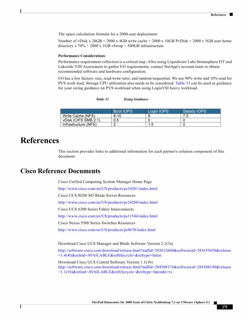
References
The space calculation formula for a 2000-seat deployment:
Number of vDisk x 20GB + 2000 x 4GB write cache + 2000 x 10GB PvDisk + 2000 x 5GB user home directory x 70% + 2000 x 1GB vSwap + 500GB infrastructure
Performance Considerations
Performance requirement collection is a critical step. After using Liquidware Labs Stratusphere FIT and Lakeside VDI Assessment to gather I/O requirements, contact NetApp's account team to obtain recommended software and hardware configuration.
I/O has a few factors: size, read/write ratio, and random/sequential. We use 90% write and 10% read for PVS work load. Storage CPU utilization also needs to be considered. Table 33 can be used as guidance for your sizing guidance on PVS workload when using LoginVSI heavy workload.
Table 33 Sizing Guidance
ReferencesThis section provides links to additional information for each partner's solution component of this document.
Cisco Reference Documents
Cisco Unified Computing System Manager Home Page
http://www.cisco.com/en/US/products/ps10281/index.html
Cisco UCS B200 M3 Blade Server Resources
http://www.cisco.com/en/US/products/ps10280/index.html
Cisco UCS 6200 Series Fabric Interconnects
http://www.cisco.com/en/US/products/ps11544/index.html
Cisco Nexus 5500 Series Switches Resources
http://www.cisco.com/en/US/products/ps9670/index.html
Download Cisco UCS Manager and Blade Software Version 2.1(3a)
http://software.cisco.com/download/release.html?mdfid=283612660&softwareid=283655658&release=1.4(4l)&relind=AVAILABLE&rellifecycle=&reltype=latest
Download Cisco UCS Central Software Version 1.1(1b) http://software.cisco.com/download/release.html?mdfid=284308174&softwareid=284308194&release=1.1(1b)&relind=AVAILABLE&rellifecycle=&reltype=latest&i=rs
Boot IOPS Login IOPS Steady IOPSWrite Cache (NFS) 8-10 9 7.5vDisk (CIFS SMB 2.1) 0.5 0 0Infrastructure (NFS) 2 1.5 0
275FlexPod Datacenter for 2000 Seats of Citrix XenDesktop 7.1 on VMware vSphere 5.1
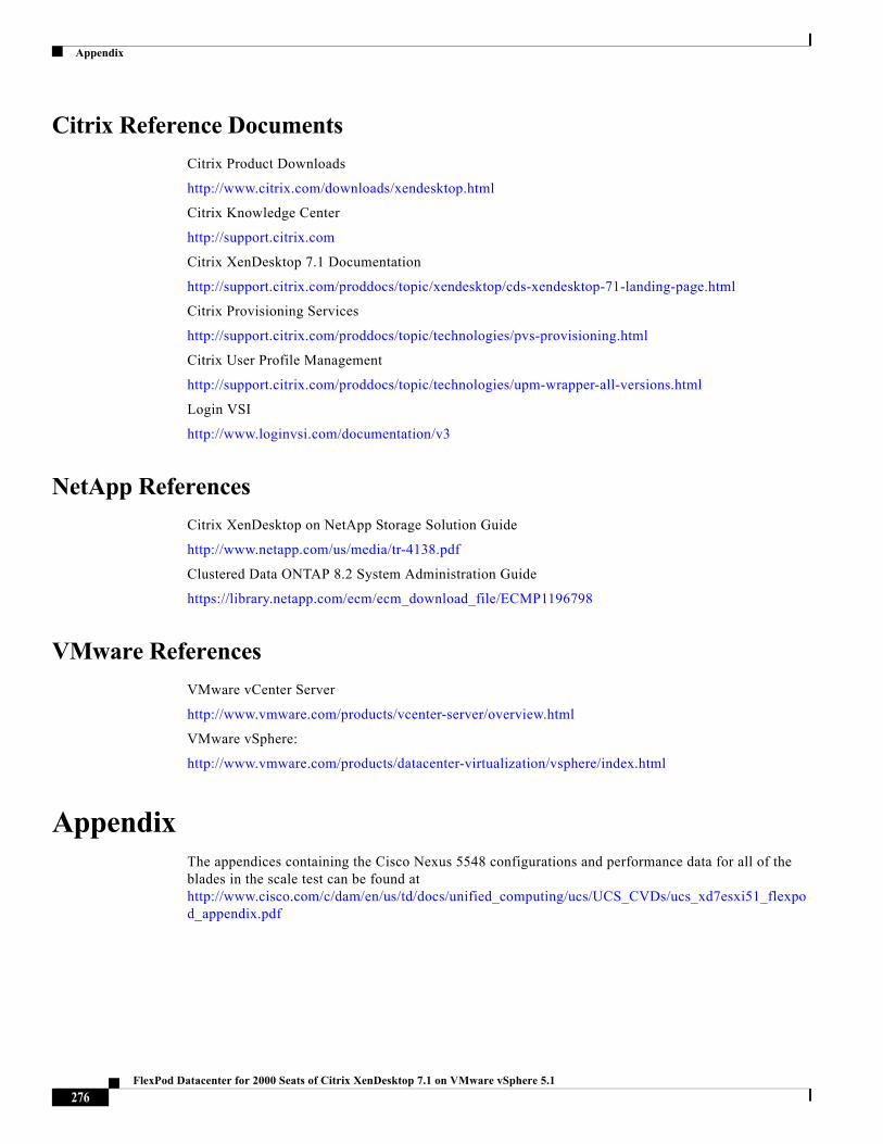
Appendix
Citrix Reference Documents
Citrix Product Downloads
http://www.citrix.com/downloads/xendesktop.html
Citrix Knowledge Center
http://support.citrix.com
Citrix XenDesktop 7.1 Documentation
http://support.citrix.com/proddocs/topic/xendesktop/cds-xendesktop-71-landing-page.html
Citrix Provisioning Services
http://support.citrix.com/proddocs/topic/technologies/pvs-provisioning.html
Citrix User Profile Management
http://support.citrix.com/proddocs/topic/technologies/upm-wrapper-all-versions.html
Login VSI
http://www.loginvsi.com/documentation/v3
NetApp References
Citrix XenDesktop on NetApp Storage Solution Guide
http://www.netapp.com/us/media/tr-4138.pdf
Clustered Data ONTAP 8.2 System Administration Guide
https://library.netapp.com/ecm/ecm_download_file/ECMP1196798
VMware References
VMware vCenter Server
http://www.vmware.com/products/vcenter-server/overview.html
VMware vSphere:
http://www.vmware.com/products/datacenter-virtualization/vsphere/index.html
AppendixThe appendices containing the Cisco Nexus 5548 configurations and performance data for all of the blades in the scale test can be found at http://www.cisco.com/c/dam/en/us/td/docs/unified_computing/ucs/UCS_CVDs/ucs_xd7esxi51_flexpod_appendix.pdf
276FlexPod Datacenter for 2000 Seats of Citrix XenDesktop 7.1 on VMware vSphere 5.1