Flatness characteristics for diagonal scans from Varian and Siemens linear accelerators
3
rL ADIOTHERAPY & ONCOLOGY ELSEVIER Radiotherapy and Oncology 40 (1996) 281-283 Technical Note Flatness characteristics for diagonal scans from Varian and Siemens linear accelerators Julie Dawsona’*, Darren Kahler”, Jean Gu”, Bob McDonald”, Fred Abrath”, Walter Kopeckyb “Radiation Oncology Department, Saint Louis University Health Sciences Center, 3635 Vista Avenue at Grand Boulevard, St. Louis, MO 63110-0250, USA bMedical Physics Associates, 342 Royal Valley, St. Louis, MO 63141, USA Received 8 August 1995; revised 15 March 1996; accepted 25 April 1996 Abstract The advent of 3D treatment planning systems whose algorithms utilize diagonal scan data to perform dose calculations has made the collection of diagonal profile data essential. Manufacturers’ specifications (MS) on beam flatness and symmetry apply to both the radial and transverse axes of all square field sizes from 10 X 10 cm* to the largest field available. Beam profile measurements were obtained for both diagonal axes over a range of field sizes and depths for two units, a Varian 2100C and a Siemens KD. In this note the International Electrotechnical Commission (IEC) flatness definition was used to characterize the diagonal flatness of each beam. Keywords: Diagonal scans; Flatness characteristics; Machine comparison 1. Introduction The advent of 3D treatment planning systems whose algorithms utilize diagonal scan data to perform dose calculations has made the collection of diagonal profile data necessary. Flatness (F) and symmetry (S) specifica- tions for radial and transverse X-ray beam profiles are provided by the machine manufacturer. Typical specifica- tions are 23% on F and k 1% to 22% on S over the central 80% of the beam for profiles taken in principal transverse or radial planes. The machine manufacturer does not routinely provide F and S specifications for diagonal scans. Little exists in the literature on the collection and analysis of diagonal scan data. Different definitions exist for F and S, so manufacturer specifications may refer to the limits on F and S with respect to the central axis value, or with respect to an average profile value. The manufacturers of the units presented in this study (Varian and Siemens) define F as the variation of X-ray dose, with respect to the mean dose, delivered within the central 80% of the field as measured *Corresponding author. Radiation Oncology Department, Saint Louis University Health Sciences Center, 3635 Vista Avenue at Grand Boulevard, St. Louis, MO 63110-0250, USA. at the nominal SSD for a selected depth. The mean dose is the average of the maximum and minimum points within the central 80% of the beam. Khan [3] discusses the need for standard criteria on flatness and symmetry. Boyer [l] suggests a criterion for F on diagonal scans of +4% to -6% within a region extending up to 2.8 cm from the field edge defined by the 50% isodose curve at a depth of 10 cm. Palta [4] states manufacturer specifications for diagonal scans in accordance with criteria recommended by the International Electrotechnical Commission (IEC). The IEC defines flatness for diagonal scans as the ratio of maximum absorbed dose to minimum absorbed dose over 60% of the field dimension along the diagonal at 10 cm depth. Here we report the results of field flatness for diagonal scans obtained for a number of field sizes and depths on two machines; a Varian 21OOC, and a Siemens KD. We have used the IEC definition to evaluate diagonal flatness over a range of depths of clinical interest. 2. Methods and materials Beam profile measurements were obtained for both diagonal axes over a range of field sizes and depths for two 0167-8140/96/$15.00 0 1996 Elsevier Science Ireland Ltd. All rights reserved PIZ SO167-8140(96)01794-X
-
Upload
julie-dawson -
Category
Documents
-
view
216 -
download
0
Transcript of Flatness characteristics for diagonal scans from Varian and Siemens linear accelerators

rL ADIOTHERAPY & ONCOLOGY
ELSEVIER Radiotherapy and Oncology 40 (1996) 281-283
Technical Note
Flatness characteristics for diagonal scans from Varian and Siemens linear accelerators
Julie Dawsona’*, Darren Kahler”, Jean Gu”, Bob McDonald”, Fred Abrath”, Walter Kopeckyb
“Radiation Oncology Department, Saint Louis University Health Sciences Center, 3635 Vista Avenue at Grand Boulevard, St. Louis, MO 63110-0250, USA
bMedical Physics Associates, 342 Royal Valley, St. Louis, MO 63141, USA
Received 8 August 1995; revised 15 March 1996; accepted 25 April 1996
Abstract
The advent of 3D treatment planning systems whose algorithms utilize diagonal scan data to perform dose calculations has made the collection of diagonal profile data essential. Manufacturers’ specifications (MS) on beam flatness and symmetry apply to both the radial and transverse axes of all square field sizes from 10 X 10 cm* to the largest field available. Beam profile measurements were obtained for both diagonal axes over a range of field sizes and depths for two units, a Varian 2100C and a Siemens KD. In this note the International Electrotechnical Commission (IEC) flatness definition was used to characterize the diagonal flatness of each beam.
Keywords: Diagonal scans; Flatness characteristics; Machine comparison
1. Introduction
The advent of 3D treatment planning systems whose algorithms utilize diagonal scan data to perform dose calculations has made the collection of diagonal profile data necessary. Flatness (F) and symmetry (S) specifica- tions for radial and transverse X-ray beam profiles are provided by the machine manufacturer. Typical specifica- tions are 23% on F and k 1% to 22% on S over the central 80% of the beam for profiles taken in principal transverse or radial planes. The machine manufacturer does not routinely provide F and S specifications for diagonal scans. Little exists in the literature on the collection and analysis of diagonal scan data.
Different definitions exist for F and S, so manufacturer specifications may refer to the limits on F and S with respect to the central axis value, or with respect to an average profile value. The manufacturers of the units presented in this study (Varian and Siemens) define F as the variation of X-ray dose, with respect to the mean dose, delivered within the central 80% of the field as measured
*Corresponding author. Radiation Oncology Department, Saint Louis University Health Sciences Center, 3635 Vista Avenue at Grand Boulevard, St. Louis, MO 63110-0250, USA.
at the nominal SSD for a selected depth. The mean dose is the average of the maximum and minimum points within the central 80% of the beam. Khan [3] discusses the need for standard criteria on flatness and symmetry.
Boyer [l] suggests a criterion for F on diagonal scans of +4% to -6% within a region extending up to 2.8 cm from the field edge defined by the 50% isodose curve at a depth of 10 cm. Palta [4] states manufacturer specifications for diagonal scans in accordance with criteria recommended by the International Electrotechnical Commission (IEC). The IEC defines flatness for diagonal scans as the ratio of maximum absorbed dose to minimum absorbed dose over 60% of the field dimension along the diagonal at 10 cm depth.
Here we report the results of field flatness for diagonal scans obtained for a number of field sizes and depths on two machines; a Varian 21OOC, and a Siemens KD. We have used the IEC definition to evaluate diagonal flatness over a range of depths of clinical interest.
2. Methods and materials
Beam profile measurements were obtained for both diagonal axes over a range of field sizes and depths for two
0167-8140/96/$15.00 0 1996 Elsevier Science Ireland Ltd. All rights reserved PIZ SO167-8140(96)01794-X
282 J. Dawson et al. I Radiotherapy and Oncology 40 (1996) 281-283
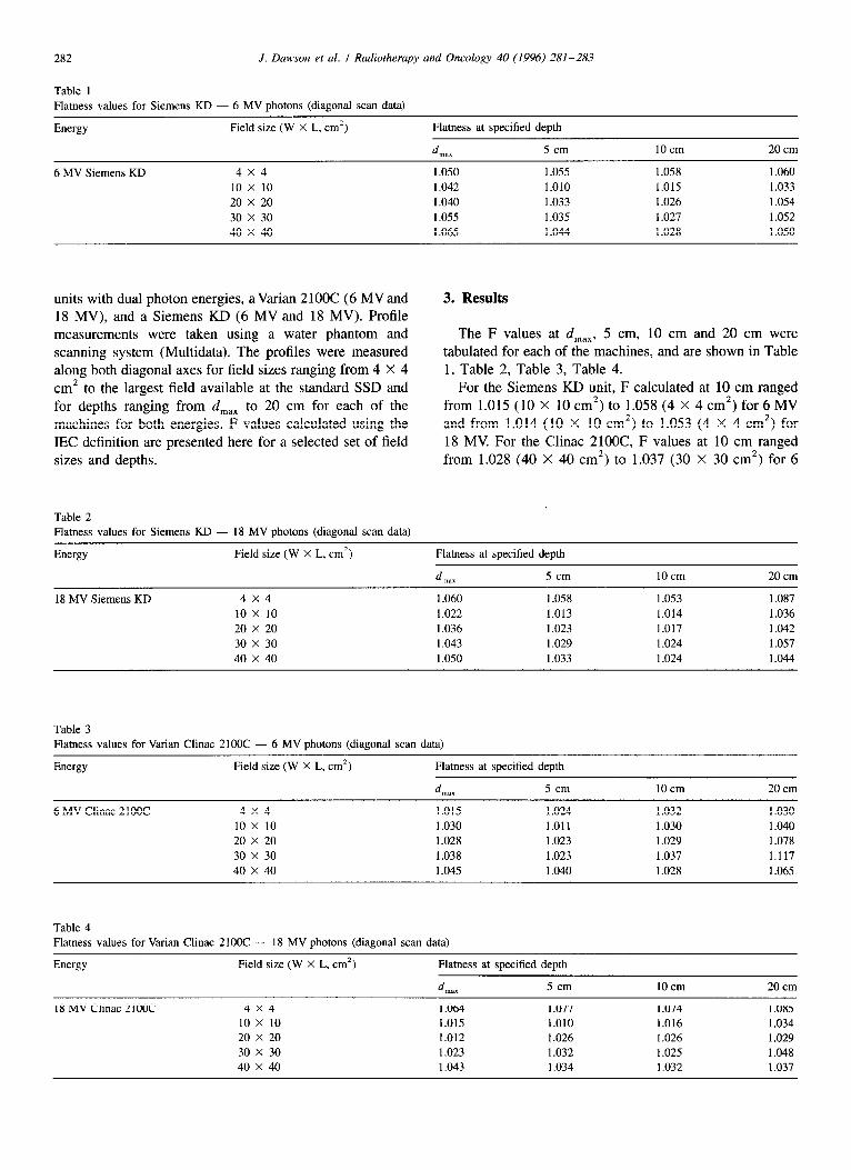
Table 1 Flatness values for Siemens KD - 6 MV photons (diagonal scan data)
Energy Field size (W X L, cm2)
6 MV Siemens KD 4X4 10 x 10 20 x 20 30 x 30 40 x 40
Flatness at specified depth
d max 5 cm
1.050 1.055 1.042 1.010 1.040 1.033 1.055 1.035 1.065 1.044
10 cm 20 cm
1.058 1.060 1.015 1.033 1.026 1.054 1.027 1.052 1.028 1.050
units with dual photon energies, a Varian 2100C (6 MV and 18 MV), and a Siemens KD (6 MV and 18 MV). Profile measurements were taken using a water phantom and scanning system (Multidata). The profiles were measured along both diagonal axes for field sizes ranging from 4 X 4 cm* to the largest field available at the standard SSD and for depths ranging from d,,, to 20 cm for each of the machines for both energies. F values calculated using the IEC definition are presented here for a selected set of field sizes and depths.
3. Results
The F values at d,,,, 5 cm, 10 cm and 20 cm were tabulated for each of the machines, and are shown in Table 1, Table 2, Table 3, Table 4.
For the Siemens KD unit, F calculated at 10 cm ranged from 1.015 (10 X 10 cm*) to 1.058 (4 X 4 cm*) for 6 MV and from 1.014 (10 X 10 cm*) to 1.053 (4 X 4 cm’) for 18 MV. For the Clinac 21OOC, F values at 10 cm ranged from 1.028 (40 X 40 cm2) to 1.037 (30 X 30 cm*) for 6
Table 2 Flatness values for Siemens KD - 18 MV photons (diagonal scan data)
Energy Field size (W X L, cm’) Flatness at specified depth
d Illax 5 cm 10 cm 20 cm
18 MV Siemens KD 4x4 1.060 1.058 1.053 1.087 10 x 10 1.022 1.013 1.014 1.036 20 x 20 1.036 1.023 1.017 1.042 30 x 30 1.043 1.029 1.024 1.057 40 x 40 1.050 1.033 1.024 1.044
Table 3 Flatness values for Varian Clinac 21OOC - 6 MV photons (diagonal scan data)
Energy Field size (W X L, cm’) Flatness at specified depth
d max 5 cm 1Ocm 20 cm
6 MV Clinac 21OOC 4x4 1.015 1.024 1.032 1.030 10 x 10 1.030 1.011 1.030 1.040 20 x 20 1.028 1.023 1.029 1.078 30 x 30 1.038 1.023 1.037 1.117 40 x 40 1.045 1.040 1.028 1.065
Table 4 Flatness values for Varian Clinac 2100C - 18 MV photons (diagonal scan data)
Energy Field size (W X L, cm*) Flatness at specified depth
d max 5 cm 10 cm 20 cm
18 MV Clinac 2100C 4x4 1.064 1.077 1.074 1.085 10 x 10 1.015 1.010 1.016 1.034 20 x 20 1.012 1.026 1.026 1.029 30 x 30 1.023 1.032 1.025 1.048 40 x 40 1.043 1.034 1.032 1.037

J. Dawson et al. I Radiotherapy and Oncology 40 (1996) 281-28.3 283
MV and from 1.016 (10 X 10 cm’) to 1.074 (4 X 4 cm’) for 18 MV. The IEC recommends that F (calculated at 10 cm) should be less or equal to 1.06. If the smallest field size studied (4 X 4 cm*) is excluded, F values at 10 cm depth were less than 1.04 for all energies studied. At depths other than 10 cm, F values were less than 1.09.
onal scan data from the largest field to construct a computational matrix that is used by the dose calculation algorithm to compute the dose. The variation in F with field size observed here suggests that using data for the largest scan only will result in dose computations that may be unrealistic for smaller fields (4 X 4 cm*).
4. Conclusions References
The IEC recommendation for F of 1.06 at 10 cm depth is met for all field sizes and energies studied with the exception of one case (F = 1.074). At other depths, F values range from 1.01 to 1.09.
3D-treatment planning systems (3D-TPS) utilizing diag-
[ 11 Boyer A.L. QA foundations in equipment specifications, acceptance testing and commissioning. In: Quality Assurance in Radiotherapy Physics, pp. 14-18. Medical Physics Publishing, Madison, 1991,
[2] C.M.S. FOCUS Release 1.1.0 Reference Guide, 1995. [3] Khan F.M. The Physics of Radiation Therapy, 2nd edn., pp. 524-
526. Williams & Wilkins. Baltimore. 1994. onal scan data require data for the largest field size for each SSD of the machine. The 3D-TPS acquired by our institution [2] interpolates and extrapolates the raw diag-
[4] Palta, J.R., Ayyangar, K., Daftari, I. and Suntharalingam, N. Characteristics of photon beams from Philips SL25 linear accelerators. Med. Phys. 17: 106-I 16, 1990.