
Firmware Loading Instructions · MX, MXa, QX and UEX actuator, including CPLD and bootloader...
22
Firmware Loading Instructions Purpose To provide the end user with a comprehensive, step-by-step guide for verifying and uploading firmware into the Flowserve MX, MXa, QX and UEX actuator, including CPLD and bootloader upgrades. Hardware Requirements Personal Laptop Computer with Windows 2000/XP (or later) Operating System WITH a functioning serial port. (This is the preferred configuration. If the platform does not have a functioning serial port, then a Sealevel 2105 USB to RS-232 DB9 Serial Interface Adapter is required) Actisys IR Computer Link, P/N: ACT-IR220LN19 Software Requirements Flowserve SMT and/or MXa Downloader Software Appropriate MX, MXa, QX or UEX Firmware files Flowserve ModTest Utility Software NOTE Before updating any firmware or bootloader file, insure you are using the latest version released. This can be accomplished by either contacting your Flowserve Service Coordinator directly for a copy of the files or requesting to be put on the distribution list. If requesting to be put on the distribution, a valid e-mail address is required. NOTE Before performing any maintenance or service action on an actuator (including firmware upgrade), ALWAYS record ALL operational and configuration data. Optional Equipment Local Port adapter cable Rev_July_2015
Transcript of Firmware Loading Instructions · MX, MXa, QX and UEX actuator, including CPLD and bootloader...

Firmware Loading Instructions Purpose To provide the end user with a comprehensive, step-by-step guide for verifying and uploading firmware into the Flowserve MX, MXa, QX and UEX actuator, including CPLD and bootloader upgrades. Hardware Requirements Personal Laptop Computer with Windows 2000/XP (or later) Operating System WITH a functioning serial port. (This is the preferred configuration. If the platform does not have a functioning serial port, then a Sealevel 2105 USB to RS-232 DB9 Serial Interface Adapter is required) Actisys IR Computer Link, P/N: ACT-IR220LN19 Software Requirements Flowserve SMT and/or MXa Downloader Software Appropriate MX, MXa, QX or UEX Firmware files Flowserve ModTest Utility Software
NOTE Before updating any firmware or bootloader file, insure you are using the latest version released. This can be accomplished by either contacting your Flowserve Service Coordinator directly for a copy of the files or requesting to be put on the distribution list. If requesting to be put on the distribution, a valid e-mail address is required.
NOTE Before performing any maintenance or service action on an actuator (including firmware upgrade), ALWAYS record ALL
operational and configuration data. Optional Equipment Local Port adapter cable
Rev_July_2015

SerialComm TTL-232-5P (includes TTL converter and terminal interface)
12
34
5N
CIN TT
LO
UT
TTL
NC
GN
D
SerialCommTTL-232-5P
RS-232 5V
TTL
5
32
Interface Terminal MX (old) MX (new) MXa QX UEX
2 27 11 39 3 26 10 38 5 28 19 37
NOTE Read the complete procedure before attempting to update any firmware. When running the downloader, close all other programs that could potentially utilize the Com port resources. Once all of the basic requirements are in place, you can begin to configure the computer to utilize the IR Computer Link to interface with the IRDA Port on the actuator. Follow the supplied instructions for the IR Link (and Sealevel Interface, if necessary) installation and the appropriate drivers which are available from the Actisys website (and delivered with the Sealevel Interface device). When you have the IR Link and drivers installed, load the downloader software and save the firmware files on your computer. Once all files, software and hardware have been installed and configured, it is time to start the firmware upgrade process. If using the Local Port adapter, connect the terminals according to the wiring chart IR Port Activation Enter the SETUP Menu Toggle “NO” to all menu options until “CHANGE PORT” is displayed, then toggle “YES” Enable the IRDA port, and then exit SETUP
Rev_July_2015
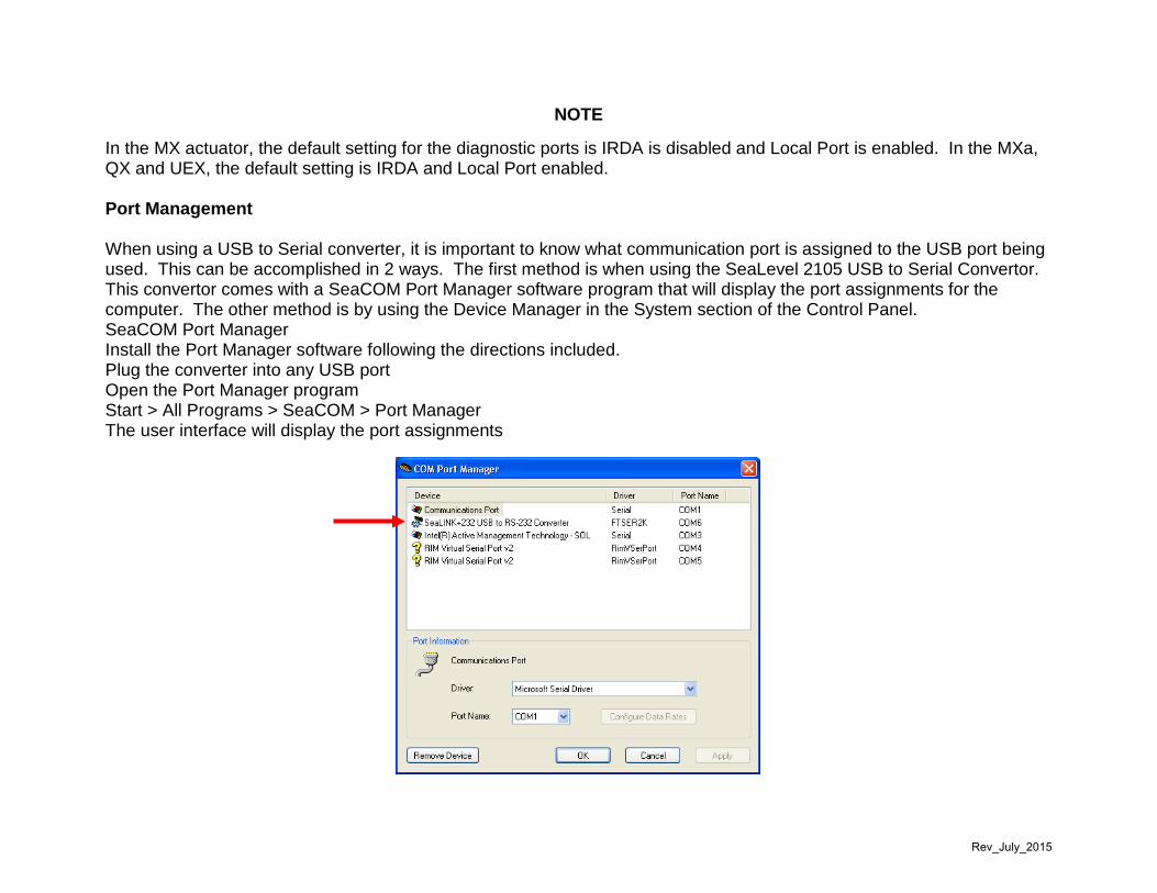
NOTE In the MX actuator, the default setting for the diagnostic ports is IRDA is disabled and Local Port is enabled. In the MXa, QX and UEX, the default setting is IRDA and Local Port enabled. Port Management When using a USB to Serial converter, it is important to know what communication port is assigned to the USB port being used. This can be accomplished in 2 ways. The first method is when using the SeaLevel 2105 USB to Serial Convertor. This convertor comes with a SeaCOM Port Manager software program that will display the port assignments for the computer. The other method is by using the Device Manager in the System section of the Control Panel. SeaCOM Port Manager Install the Port Manager software following the directions included. Plug the converter into any USB port Open the Port Manager program Start > All Programs > SeaCOM > Port Manager The user interface will display the port assignments
Rev_July_2015
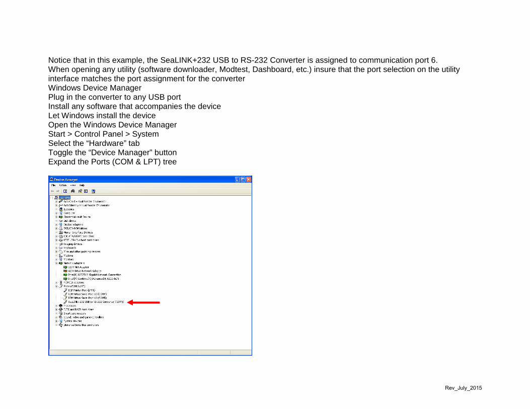
Notice that in this example, the SeaLINK+232 USB to RS-232 Converter is assigned to communication port 6. When opening any utility (software downloader, Modtest, Dashboard, etc.) insure that the port selection on the utility interface matches the port assignment for the converter Windows Device Manager Plug in the converter to any USB port Install any software that accompanies the device Let Windows install the device Open the Windows Device Manager Start > Control Panel > System Select the “Hardware” tab Toggle the “Device Manager” button Expand the Ports (COM & LPT) tree
Rev_July_2015

The port assignments are displayed Notice that in this example, the SeaLINK+232 USB to RS-232 Converter is assigned to communication port 6. When opening any utility (software downloader, Modtest, Dashboard, etc.) insure that the port selection on the utility interface matches the port assignment for the converter Verifying the Firmware Version Methods for verifying firmware versions and the data available to the user vary depending on the model of the actuator. The data available to the user in the MX-SMT differs from that of the MXa, as well as the information available from the QX and QXM. There are also similarities in the information available since the MXa, QX and QXM share identical hardware. Verifying MX-SMT Firmware The firmware version of the MX-SMT is accessed through the View Diagnostics menu
1. “SETUP?” > Toggle YES 2. “SETUP IN ENGLISH?” > Toggle YES 3. “CHANGE SETTINGS?” > Toggle NO 4. “VIEW SETTINGS?” > Toggle NO 5. “VIEW DIAGNOSTICS?” > Toggle YES 6. “VIEW HARDWARE?” > Toggle NO 7. “VIEW MOTOR STATUS?” > Toggle NO 8. “VIEW POWER SUPPLY?” > Toggle NO 9. “VIEW IDENTIFICATION?” > Toggle YES 10. “SERIAL # (NEXT)” > Toggle YES 11. “ORDER # (NEXT)” > Toggle YES 12. “FIRMWARE (NEXT)” XX/XX.XX
a. This is the current version of firmware loaded in the actuator Verifying MXa Firmware and Option Board Software Versions The firmware version of the MXa is accessed through the View Diagnostics menu. In firmware version 12M05.00 and later, the bootloader, CPLD and software revision of any option boards installed will be available to the user also.
1. “SETUP?” > Toggle YES
Rev_July_2015

2. “SETUP IN ENGLISH?” > Toggle YES 3. “CHANGE SETTINGS?” > Toggle NO 4. “VIEW SETTINGS?” > Toggle NO 5. “VIEW DIAGNOSTICS?” > Toggle YES 6. “VIEW HARDWARE?” > Toggle NO 7. “VIEW ERROR CODE?” > Toggle NO 8. “VIEW MOTOR STATUS?” > Toggle NO 9. “VIEW POWER SUPPLY?” > Toggle NO 10. “VIEW IDENTIFICATION?” > Toggle YES 11. “TAG (OK?)” > Toggle YES 12. “SERIAL # (OK?)” > Toggle YES 13. “ORDER # (OK?)” > Toggle YES 14. “FIRMWARE (OK?)” XXMXX.XX > Toggle YES 15. “BOOTLOADER FIRMWARE Ref XX” > Toggle YES 16. “CPLD FIRMWARE REV. XX” > Toggle YES 17. “ANALOG 1 FIRMWARE REV. XX” > Toggle YES
a. Will display the software revision number if the option board is installed and communicating with the main board
b. Will display NOT AVAILABLE if the option is not installed or the option board is not communicating with the main board.
18. “ANALOG 2 FIRMWARE REV. XX” > Toggle YES a. Will display the software revision number if the option board is installed and communicating with the main
board b. Will display NOT AVAILABLE if the option is not installed or the option board is not communicating with the
main board. 19. “R1 – R4RM FIRMWARE REV. XX” > Toggle YES
a. Will display the software revision number if the option board is installed and communicating with the main board
b. Will display NOT AVAILABLE if the option is not installed or the option board is not communicating with the main board.
20. “R5 – R8 FIRMWARE REV. XX” > Toggle YES a. Will display the software revision number if the option board is installed and communicating with the main
board
Rev_July_2015

b. Will display NOT AVAILABLE if the option is not installed or the option board is not communicating with the main board.
21. Network option revisions a. If a network option is installed in the actuator, the software will call out the actual protocol (DDC, FF, PB-DP,
PB-PA or DNET) and the software revision for Network A and B if installed b. If no network option is installed
i. “NETWORK A NOT AVAILABLE” ii. “NETWORK B NOT AVAILABLE”
Verifying QX and QXM Firmware and Option Board Software Versions The firmware version of the QX and QXM is accessed through the View Diagnostics menu. In firmware versions 12Q04.00 (for the QX) and 12Z04.00 (for the QXM) and later versions, the bootloader, CPLD and software revision of any option boards installed will be available to the user also.
1. “SETUP?” > Toggle YES 2. “SETUP IN ENGLISH?” > Toggle YES 3. “CHANGE SETTINGS?” > Toggle NO 4. “VIEW SETTINGS?” > Toggle NO 5. “VIEW DIAGNOSTICS?” > Toggle YES 6. “VIEW HARDWARE?” > Toggle NO 7. “VIEW ERROR CODE?” > Toggle NO 8. “VIEW MOTOR STATUS?” > Toggle NO 9. “VIEW POWER SUPPLY?” > Toggle NO 10. “VIEW IDENTIFICATION?” > Toggle YES 11. “TAG (OK?)” > Toggle YES 12. “SERIAL # (OK?)” > Toggle YES 13. “ORDER # (OK?)” > Toggle YES 14. “FIRMWARE (OK?)” XXMXX.XX > Toggle YES 15. “BOOTLOADER FIRMWARE Ref XX” > Toggle YES 16. “CPLD FIRMWARE REV. XX” > Toggle YES 17. “MC FIRMWARE REV. XX.XX.XX” Toggle YES 18. “ANALOG 1 FIRMWARE REV. XX” > Toggle YES
Rev_July_2015

a. Will display the software revision number if the option board is installed and communicating with the main board
b. Will display NOT AVAILABLE if the option is not installed or the option board is not communicating with the main board.
19. “ANALOG 2 FIRMWARE REV. XX” > Toggle YES a. Will display the software revision number if the option board is installed and communicating with the main
board b. Will display NOT AVAILABLE if the option is not installed or the option board is not communicating with the
main board. 20. “R1 – R4RM FIRMWARE REV. XX” > Toggle YES
a. Will display the software revision number if the option board is installed and communicating with the main board
b. Will display NOT AVAILABLE if the option is not installed or the option board is not communicating with the main board.
21. “R5 – R8 FIRMWARE REV. XX” > Toggle YES a. Will display the software revision number if the option board is installed and communicating with the main
board b. Will display NOT AVAILABLE if the option is not installed or the option board is not communicating with the
main board. 22. Network option revisions
a. If a network option is installed in the actuator, the software will call out the actual protocol (DDC, FF, PB-DP, PB-PA or DNET) and the software revision for Network A and B if installed
b. If no network option is installed i. “NETWORK A NOT AVAILABLE” ii. “NETWORK B NOT AVAILABLE”
Downloading MX-SMT Firmware When updating older versions of firmware to 10.12.02, the following steps MUST be taken: Background Firmware version 10.12.02 addresses the MX-SMT main board failure that was attributed to ROM Error events. Since this version of firmware utilizes different sections of the EEPROM than previous versions, once the firmware upload is
Rev_July_2015

complete the actuator will go into a re-initialization routine. This re-initialization routine will set all operating parameters to factory defaults. This includes the OPEN and CLOSE limits. It is incumbent upon the technician to record ALL operating parameters before performing this update procedure in order to return the actuator to the customer’s settings. If communication with the actuator cannot be maintained or the actuator main board is in a loop that prevents the operating parameters from being accessed, the customer must provide the operating parameters to the technician before performing this procedure. At this time, any follow-on versions of MX-SMT firmware will not require a re-initialization of the actuator.
NOTE The technician must record or obtain the operating parameters for the actuator before performing this procedure.
NOTE This firmware update (10.12.02) will re-initialize the actuator setting all parameters to factory default. This includes the OPEN and CLOSE limits. It is the technician’s responsibility to insure that the actuator/valve can be stroked to reset the OPEN and CLOSE limits before updating the firmware. Procedure
1. Record nameplate data a. MX Model b. Serial Number c. Order Number d. Voltage e. Frequency f. RPM
2. Record actuator operating parameters a. Enter the SETUP Mode
i. “SETUP?” > Toggle YES ii. “SETUP IN ENGLISH?” > Toggle YES iii. “CHANGE SETTINGS?” > Toggle NO iv. “VIEW SETTINGS?” > Toggle YES
b. Toggle YES to view the parameters for each menu option
Rev_July_2015
c. Toggle NO to select the next menu option d. Record ALL operating parameters and settings
NOTE
If the actuator main board is in a state that prevents the technician from accessing actuator operating parameters, the customer must provide the necessary information in order to return the actuator to normal operation and customer requirements.
3. Update the firmware in accordance with normal firmware updating procedures insuring that the actuator
REMOTE/STOP/LOCAL knob is in the STOP position
NOTE If the actuator main board is in a state that IR communication cannot be established, take the following steps:
1. Power the actuator OFF 2. Start the downloader process 3. Power the actuator ON 4. During the boot up sequence, the IR port will come on for a short period. During this time the IR
communication will synchronize and the upload process will continue
4. If the download process fails at this point, the alternative method of programming through the Local Port may be attempted
a. Connect the Local Port adapter harness in accordance with the Firmware Loading Procedure b. Continue with the download procedure c. If communication cannot be established and maintained, the Main Board must be replaced
5. When the upload is completed, the actuator will be in a re-initialized state 6. Answer the prompts with the data collected from Step 1
a. Actuator Model b. Voltage c. Frequency d. RPM e. Serial Number
i. This data is not required for operational functionality
Rev_July_2015

ii. The 8 characters can be accepted by toggling YES to all of them or toggling NO until the desired character is displayed and then toggling YES to accept
7. “COLD (-50C) UNIT? NO – OK” > Toggle YES a. Toggle NO only if the actuator is an Arctic duty unit
8. “INITIALIZE?” > Toggle YES a. After the actuator has re-booted, set the CLOSE and OPEN limits to meet the customer requirements
9. If the technician is prompted for a network address, enter any arbitrary number. The correct network address will be entered during the actual setup of the actuator
10. “SETUP?” > Toggle NO a. Toggling YES to this prompt will put the actuator back into the setting of OPEN and CLOSE limits
11. “EXIT SETUP?” > Toggle YES a. The actuator will go through the boot-up process then the normal display will appear indicating the position
and status of the actuator 12. Enter the SETUP Mode
a. “SETUP?” > Toggle YES b. “SETUP IN ENGLISH?” > Toggle YES c. “CHANGE SETTINGS?” > Toggle YES
13. Configure the actuator with the operating parameters recorded in Step 2 14. Return the actuator to service
Rev_July_2015

Firmware Downloading Procedure
Open downloader utility. The user interface should appear on your screen.
Click on the “Download Application” button The computer will point to a file that may or may not have the proper file for downloading. If not, then the user must browse for the location where the firmware file was stored.
NOTE
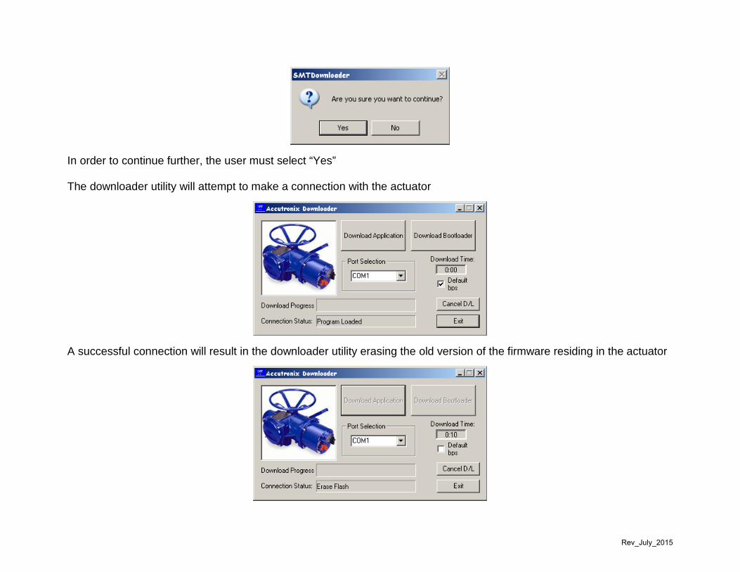
MX firmware files are designated with a “.bin” file extension. Make sure that when loading the MX actuator with firmware, you are using the file with the “.bin” file extension. Example: 10.12.01.bin. Once the file is located, double click on the file The user will then be prompted to decide whether or not they will continue
In order to continue further, the user must select “Yes” The downloader utility will attempt to make a connection with the actuator
Rev_July_2015

A successful connection will result in the downloader utility erasing the old version of the firmware residing in the actuator An unsuccessful connection will result in the Connection Status remaining in the “Attempting to Connect” state Once the connection has been established and the old application has been erased, the downloader utility will begin to write the new firmware to the actuator
When the downloader utility has successfully written the new firmware version to the actuator, the Connection Status will display “Download Complete”
Rev_July_2015

Downloading MXa Firmware Downloading firmware to the MXa actuator is performed in the same basic manner as loading firmware in the MX with some minor additions. Connectivity and manipulation of the downloader utility is identical. Open downloader utility. The user interface should appear on your screen.
Rev_July_2015

Before performing any function with the downloader interface, the user MUST check the “Default bps” block.
NOTE This is necessary when using the IR dongle to communicate with the actuator. If the user is using the Local Port Adapter cable, this step is NOT required.
Click on the “Download Application” button The computer will point to a file that may or may not have the proper file for downloading. If not, then the user must browse for the location where the firmware file was stored.
NOTE MXa firmware files are designated with a “.S19” file extension. Make sure that when loading the MXa actuator with firmware, you are using the file with the “.S19” file extension. Example: 09M02.01.s19. Once the file is located, double click on the file The user will then be prompted to decide whether or not they will continue
Rev_July_2015
In order to continue further, the user must select “Yes” The downloader utility will attempt to make a connection with the actuator
A successful connection will result in the downloader utility erasing the old version of the firmware residing in the actuator
Rev_July_2015

An unsuccessful connection will result in the Connection Status remaining in the “Attempting to Connect” state Once the connection has been established and the old application has been erased, the downloader utility will begin to write the new firmware to the actuator
When the downloader utility has successfully written the new firmware version to the actuator, the Connection Status will display “Download Complete”
Rev_July_2015

To complete the MXa firmware upgrade, other steps may be involved depending on several factors. If the Main Board P/N is 64-825-0100-4 or greater, the following upgrades must be performed. If the bootloader version is not the latest version (at the time of this document, the latest version is 8f) then, the bootloader must be updated. This is achieved in much the same manner as loading firmware. The first step is to open the downloader utility and check the “Default bps” block The next step is to select the “Download Bootloader” button. The utility will then point to the location where the bootloader file is stored (normally this is in the same location as the firmware file). If the computer does not automatically locate the file location, the user must browse for the location. Select the bootloader file. As with all MXa files, this will be identified by the “.S19” file extension. For example; “mxa_bootloader_8f.s19”. Double click on the file. A user prompt will be displayed asking the user to enter a password.
The password is: thisisdangerous Enter the password (all lower case, all one word) then select “OK” The download will proceed in the same manner as firmware, except the file is considerably smaller. If the firmware version before updating is version 09.05.05 or earlier, then the CPLD must also be updated. The CPLD code resides within the firmware code; however, in order to activate the new version of CPLD code, the user must issue a Modbus 08-328 command. If the user is not familiar with this function, they should inquire about Flowserve training to familiarize themselves with this particular utility. Upon receiving the 08-328 command, the actuator will go through a loading process that will result in abnormal screen displays
Rev_July_2015

Once the CPLD update is completed, the user must issue a Modbus 08-169 command. This command will perform a factory re-initialization of the actuator without clearing the open and close limits. The user must insure that all configuration parameters are recorded before performing this function. After the 08-169 command is issued and the unit re-boots, a 08-51 command must be issued to reload the torque parameters for the actuator. This is required for all MXa, QX and QXM actuators.
NOTE
When upgrading an actuator from a version later than 09.05.05, it is not necessary to issue the 08-328 command. For example, if updating an actuator from 09.08.01(a version later than 09.05.05) to 10.03.03, it is not necessary to perform the 08-328 step. However it is vital that the CPLD is verified. Once all configuration parameters have been returned to the customer’s settings, return the actuator to service. Loading QX and QXM Firmware QX (Quarter Turn) firmware is identified by the “.S19” file extension and the letter “Q” in the file name. For example; 10Q03.03.s19. QXM (Multi Turn) firmware is also identified by the “.S19” file extension, but it’s identifier in the code is the letter “Z”. For example 10Z03.03.
All lights on with flat line on blank display
Blue light steady on, green light blinking with
no display
MAIN 09M05.05
All lights off with firmware version
displayed
Rev_July_2015
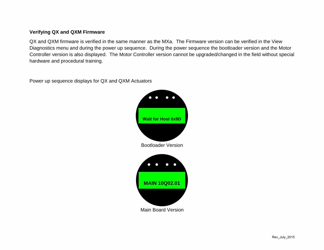
Verifying QX and QXM Firmware QX and QXM firmware is verified in the same manner as the MXa. The Firmware version can be verified in the View Diagnostics menu and during the power up sequence. During the power sequence the bootloader version and the Motor Controller version is also displayed. The Motor Controller version cannot be upgraded/changed in the field without special hardware and procedural training.
Power up sequence displays for QX and QXM Actuators
Bootloader Version
MAIN 10Q02.01
Main Board Version
Wait for Host 0x8D
Rev_July_2015
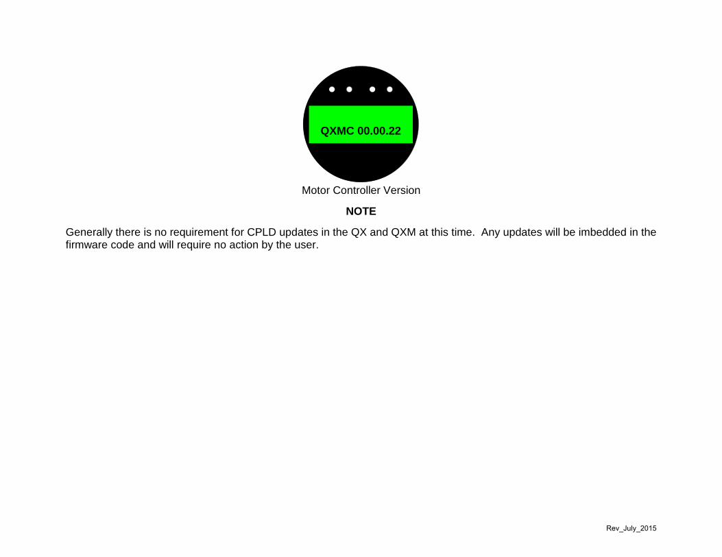
QXMC 00.00.22
Motor Controller Version
NOTE
Generally there is no requirement for CPLD updates in the QX and QXM at this time. Any updates will be imbedded in the firmware code and will require no action by the user.
Rev_July_2015

UEX (under development) Firmware The UEX control package is comprised of MXa components and as far as firmware loading is performed in the same manner as the MXa, QX and QXM. UEX firmware is identified with the “.S19” file extension and the identifying feature in the code name is the letter “U”. For example; 10U03.03. At this time, there are no special instructions for loading firmware in the UEX.
Rev_July_2015