fire and Sound ratings - National Gypsum · 2017-07-28 · 32 Rev. 07/2017 National Gypsum Company...
35
Rev. 07/2017 National Gypsum Company Construction Guide 32 NATIONAL GYPSUM ® COMPANY Fire / Sound Selector Fire And Sound Selector Fire and Sound Ratings FIRE RATINGS Fire resistance is the ability of an assembly constructed in a laboratory to contain a fire in a carefully controlled test setting for a specified period of time. ASTM E119, Standard Test Methods for Fire Tests of Building Construction and Materials, is the test standard for determining the fire-resistance rating of partitions, floor-ceiling assemblies, roof-ceiling assemblies, beams and columns. Fire tests may be conducted at any one of several recognized facilities. Fire-resistance ratings represent the results of tests on assemblies made up of specific materials in a specific configuration. When selecting construction designs to meet certain fire-resistance require- ments, caution must be used to ensure that each component of the assembly is the one specified in the test. Further, precaution should be taken that assembly procedures are in accordance with those of the tested assembly. For copies of specific tests, call 1-800-NATIONAL. SOUND RATINGS Gypsum board assemblies are laboratory tested to establish their sound insulation characteristics. Airborne sound insulation is reported as the Sound Transmission Class (STC). Impact noise, tested on floor-ceiling systems only, is reported as the Impact Insulation Class (IIC). ASTM E90, Standard Test Method for Laboratory Measurement of Airborne Sound Transmission Loss of Building Partitions and Elements, is the test standard for airborne sound reduction. The test measures the sound transmission loss at 16 one-third octave frequencies to generate a single-number acoustical rating. When selecting systems based on laboratory performance ratings, it should be understood that field conditions such as flanking paths or air leaks caused by design or workmanship can reduce acoustical performance. For this reason, National Gypsum Company cannot guarantee the performance ratings of specific assemblies in the field. To achieve maximum sound isolation from an assembly, follow published construction details completely. Use non-hardening acoustical sealant at penetrations and floor, ceiling and wall intersections to prevent flanking paths for sound.
Transcript of fire and Sound ratings - National Gypsum · 2017-07-28 · 32 Rev. 07/2017 National Gypsum Company...
Rev. 07/2017 National Gypsum Company Construction Guide32
NATIONAL GYPSUM® COMPANY
fire / S
ou
nd
Sele
ctor
Fire And Sound Selector
fire and Sound ratings
fIre raTINGS
Fire resistance is the ability of an assembly constructed in a laboratory to contain a fire in a carefully
controlled test setting for a specified period of time. ASTM E119, Standard Test Methods for Fire
Tests of Building Construction and Materials, is the test standard for determining the fire-resistance
rating of partitions, floor-ceiling assemblies, roof-ceiling assemblies, beams and columns. Fire tests
may be conducted at any one of several recognized facilities.
Fire-resistance ratings represent the results of tests on assemblies made up of specific materials in a
specific configuration. When selecting construction designs to meet certain fire-resistance require-
ments, caution must be used to ensure that each component of the assembly is the one specified
in the test. Further, precaution should be taken that assembly procedures are in accordance with
those of the tested assembly. For copies of specific tests, call 1-800-NATIONAL.
SouNd raTINGS
Gypsum board assemblies are laboratory tested to establish their sound insulation characteristics.
Airborne sound insulation is reported as the Sound Transmission Class (STC). Impact noise, tested on
floor-ceiling systems only, is reported as the Impact Insulation Class (IIC). ASTM E90, Standard Test
Method for Laboratory Measurement of Airborne Sound Transmission Loss of Building Partitions
and Elements, is the test standard for airborne sound reduction. The test measures the sound
transmission loss at 16 one-third octave frequencies to generate a single-number acoustical rating.
When selecting systems based on laboratory performance ratings, it should be understood that
field conditions such as flanking paths or air leaks caused by design or workmanship can reduce
acoustical performance. For this reason, National Gypsum Company cannot guarantee the
performance ratings of specific assemblies in the field.
To achieve maximum sound isolation from an assembly, follow published construction details
completely. Use non-hardening acoustical sealant at penetrations and floor, ceiling and wall
intersections to prevent flanking paths for sound.
National Gypsum Company Construction Guide Rev. 07/2017 33
fire
/ S
ou
nd
Sele
cto
r
General Notes Regarding Fire-Rated Assemblies
1. Unless otherwise specified, the face layers of all assemblies,
except those with predecorated surfaces or exterior gypsum
sheathing, shall have joints taped and fastener heads treated
(minimum Level 1 as specified in GA-214, Recommended Levels
of Finish for Gypsum Board, Glass Mat and Fiber-Reinforced
Gypsum Panels). Base layers in multi-layer assemblies shall not
be required to have joints or fasteners taped or covered with
joint compound.
2. When not specified as a component of a fire-tested wall or
partition assembly, mineral fiber, glass fiber, or cellulose fiber
insulation of a thickness not exceeding that of the stud depth
shall be permitted to be added within the stud cavity.
3. In floor-ceiling or roof-ceiling assemblies, the addition or deletion
of mineral wool or glass fiber insulation in the concealed space
between the ceiling membrane and the floor or roof structure
could possibly reduce the fire-resistance rating. The addition
of insulation to any one- or two-hour fire-resistance rated
floor-ceiling or roof-ceiling assembly is permitted provided
that one additional layer of gypsum board of the same type
specified in the design is added to the ceiling.
4. Additional layers of gypsum board are permitted to be added
to any assembly.
5. Stud sizes specified in wood- or steel-stud assemblies are
minimums.
6. Stud spacings specified in wood- or steel-stud assemblies are
maximums.
7. Beam, joist and truss dimensions specified in floor-ceiling or
roof-ceiling assemblies are minimums.
8. Beam, joist and truss spacings specified in floor-ceiling or
roof-ceiling assemblies are maximums.
9. The distance between parallel rows of studs in wood- or
steel-stud assemblies are minimums.
10. Ceilings supported directly from structural members are
permitted to be suspended provided the in place stiffness is
equivalent to the tested assembly.
The following gypsum board system details are intended solely
as technical support incident to the sale and use of National
Gypsum Company products. They may be used as a reference
by architects, engineers, other design professionals, contractors,
building code officials, or other competent construction industry
trade personnel considering the selection, specification and use
of National Gypsum Company products in these systems.
Architects, engineers, designers or contractors involved should
review these details with the governing code or inspection official
at the time of the job submittal to determine if there are any
discrepancies with local code or regulatory requirements. In any
event, they must NOT be used without a complete evaluation
by the owner's design professional to verify the suitability of the
system for a given application.
These system details may be printed and/or transferred electroni-
cally as needed by the user, subject to terms and limitations of
any applicable license agreement. Any unauthorized duplication
or reuse of the material contained herein is a violation of law.
For fire-safety information relating to certain systems
described in this guide, please refer to the information on
National Gypsum Company's website at:
http://nationalgypsum.com/ng/resources/fire-safety.htm.
NATIONAL GYPSUM® COMPANY
Fire And Sound Selector
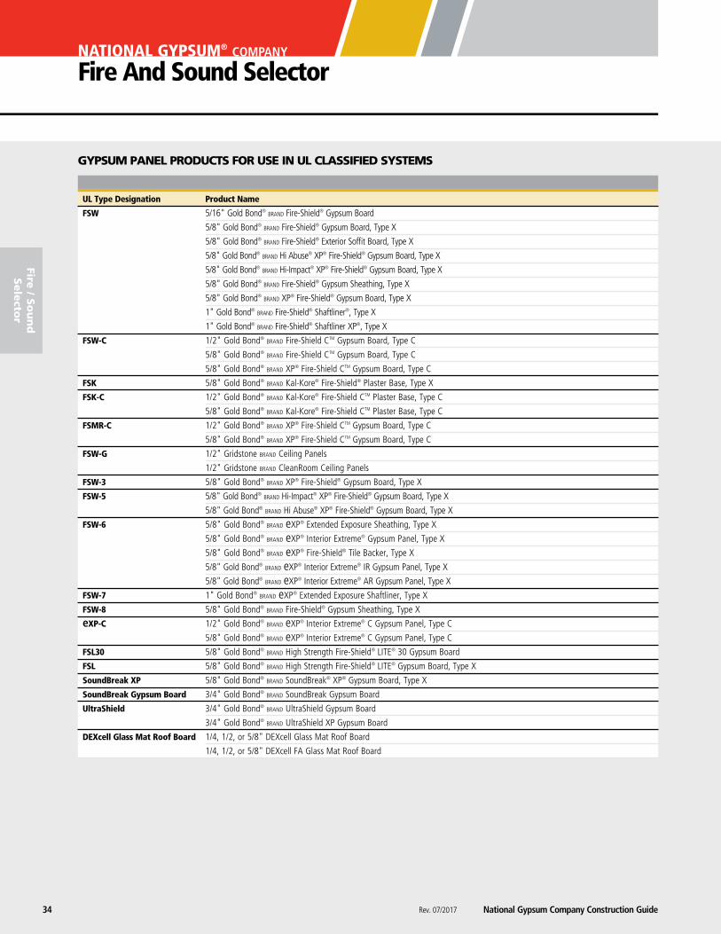
UL Type Designation Product Name
FSW 5/16" Gold Bond® brand Fire-Shield® Gypsum Board
5/8" Gold Bond® brand Fire-Shield® Gypsum Board, Type X
5/8" Gold Bond® brand Fire-Shield® Exterior Soffit Board, Type X
5/8" Gold Bond® brand Hi Abuse® XP® Fire-Shield® Gypsum Board, Type X
5/8" Gold Bond® brand Hi-Impact® XP® Fire-Shield® Gypsum Board, Type X
5/8" Gold Bond® brand Fire-Shield® Gypsum Sheathing, Type X
5/8" Gold Bond® brand XP® Fire-Shield® Gypsum Board, Type X
1" Gold Bond® brand Fire-Shield® Shaftliner®, Type X
1" Gold Bond® brand Fire-Shield® Shaftliner XP®, Type X
FSW-C 1/2" Gold Bond® brand Fire-Shield CTM Gypsum Board, Type C
5/8" Gold Bond® brand Fire-Shield CTM Gypsum Board, Type C
5/8" Gold Bond® brand XP® Fire-Shield CTM Gypsum Board, Type C
FSK 5/8" Gold Bond® brand Kal-Kore® Fire-Shield® Plaster Base, Type X
FSK-C 1/2" Gold Bond® brand Kal-Kore® Fire-Shield CTM Plaster Base, Type C
5/8" Gold Bond® brand Kal-Kore® Fire-Shield CTM Plaster Base, Type C
FSMR-C 1/2" Gold Bond® brand XP® Fire-Shield CTM Gypsum Board, Type C
5/8" Gold Bond® brand XP® Fire-Shield CTM Gypsum Board, Type C
FSW-G 1/2" Gridstone brand Ceiling Panels
1/2" Gridstone brand CleanRoom Ceiling Panels
FSW-3 5/8" Gold Bond® brand XP® Fire-Shield® Gypsum Board, Type X
FSW-5 5/8" Gold Bond® brand Hi-Impact® XP® Fire-Shield® Gypsum Board, Type X
5/8" Gold Bond® brand Hi Abuse® XP® Fire-Shield® Gypsum Board, Type X
FSW-6 5/8" Gold Bond® brand eXP® Extended Exposure Sheathing, Type X
5/8" Gold Bond® brand eXP® Interior Extreme® Gypsum Panel, Type X
5/8" Gold Bond® brand eXP® Fire-Shield® Tile Backer, Type X
5/8" Gold Bond® brand eXP® Interior Extreme® IR Gypsum Panel, Type X
5/8" Gold Bond® brand eXP® Interior Extreme® AR Gypsum Panel, Type X
FSW-7 1" Gold Bond® brand eXP® Extended Exposure Shaftliner, Type X
FSW-8 5/8" Gold Bond® brand Fire-Shield® Gypsum Sheathing, Type X
eXP-C 1/2" Gold Bond® brand eXP® Interior Extreme® C Gypsum Panel, Type C
5/8" Gold Bond® brand eXP® Interior Extreme® C Gypsum Panel, Type C
FSL30 5/8" Gold Bond® brand High Strength Fire-Shield® LITE® 30 Gypsum Board
FSL 5/8" Gold Bond® brand High Strength Fire-Shield® LITE® Gypsum Board, Type X
SoundBreak XP 5/8" Gold Bond® brand SoundBreak® XP® Gypsum Board, Type X
SoundBreak Gypsum Board 3/4" Gold Bond® brand SoundBreak Gypsum Board
UltraShield 3/4" Gold Bond® brand UltraShield Gypsum Board
3/4" Gold Bond® brand UltraShield XP Gypsum Board
DEXcell Glass Mat Roof Board 1/4, 1/2, or 5/8" DEXcell Glass Mat Roof Board
1/4, 1/2, or 5/8" DEXcell FA Glass Mat Roof Board
GypSum paNel produCTS for uSe IN ul ClaSSIfIed SySTemS
Rev. 07/2017 National Gypsum Company Construction Guide34
fire / S
ou
nd
Sele
ctor
National Gypsum Company Construction Guide Rev. 07/2017 35
09 29 00/NGC
fire
/ S
ou
nd
Sele
cto
r
Fire UL/GA Item No. Rating Design Description STC Test No.
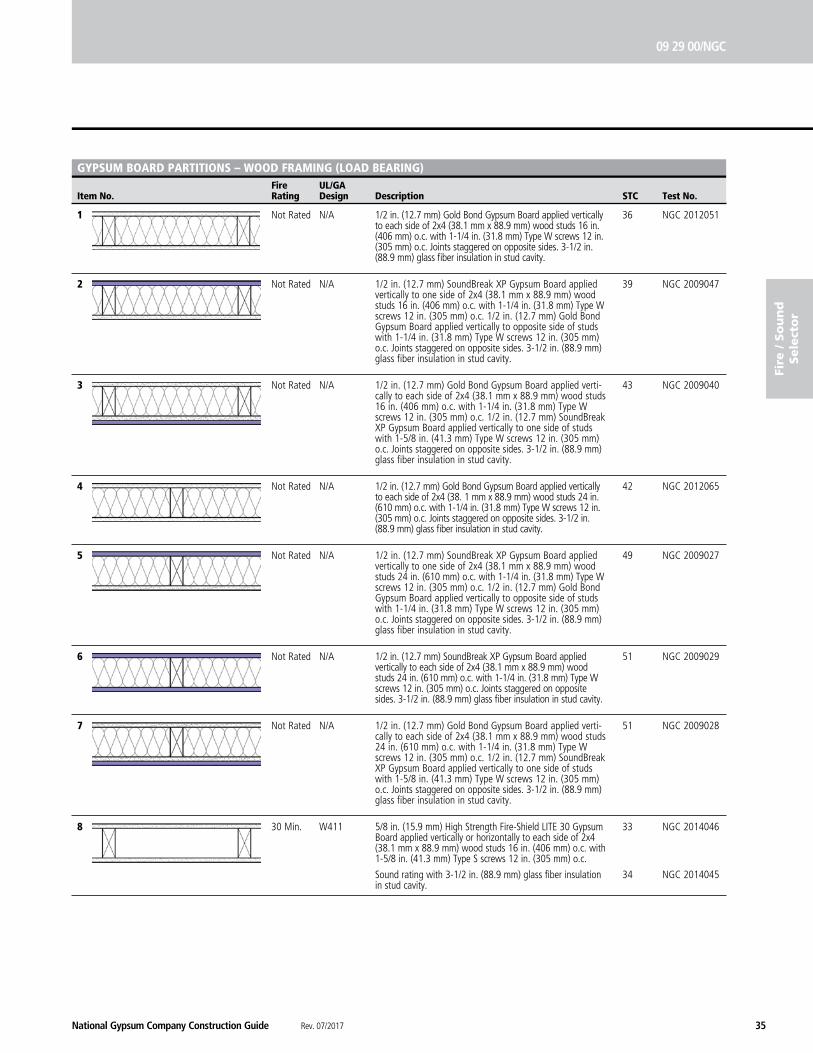
GYPSUM BOARD PARTITIONS – WOOD FRAMING (LOAD BEARING)
1 Not Rated N/A 36 NGC 2012051
2 Not Rated N/A 39 NGC 2009047
3 Not Rated N/A 43 NGC 2009040
4 Not Rated N/A 42 NGC 2012065
5 Not Rated N/A 49 NGC 2009027
6 Not Rated N/A 51 NGC 2009029
7 Not Rated N/A 51 NGC 2009028
8 30 Min. W411 33 NGC 2014046 34 NGC 2014045
1/2 in. (12.7 mm) SoundBreak XP Gypsum Board applied vertically to each side of 2x4 (38.1 mm x 88.9 mm) wood studs 24 in. (610 mm) o.c. with 1-1/4 in. (31.8 mm) Type W screws 12 in. (305 mm) o.c. Joints staggered on opposite sides. 3-1/2 in. (88.9 mm) glass fiber insulation in stud cavity.
1/2 in. (12.7 mm) Gold Bond Gypsum Board applied verti-cally to each side of 2x4 (38.1 mm x 88.9 mm) wood studs 24 in. (610 mm) o.c. with 1-1/4 in. (31.8 mm) Type W screws 12 in. (305 mm) o.c. 1/2 in. (12.7 mm) SoundBreak XP Gypsum Board applied vertically to one side of studs with 1-5/8 in. (41.3 mm) Type W screws 12 in. (305 mm) o.c. Joints staggered on opposite sides. 3-1/2 in. (88.9 mm) glass fiber insulation in stud cavity.
5/8 in. (15.9 mm) High Strength Fire-Shield LITE 30 Gypsum Board applied vertically or horizontally to each side of 2x4 (38.1 mm x 88.9 mm) wood studs 16 in. (406 mm) o.c. with 1-5/8 in. (41.3 mm) Type S screws 12 in. (305 mm) o.c.
Sound rating with 3-1/2 in. (88.9 mm) glass fiber insulation in stud cavity.
1/2 in. (12.7 mm) SoundBreak XP Gypsum Board applied vertically to one side of 2x4 (38.1 mm x 88.9 mm) wood studs 24 in. (610 mm) o.c. with 1-1/4 in. (31.8 mm) Type W screws 12 in. (305 mm) o.c. 1/2 in. (12.7 mm) Gold Bond Gypsum Board applied vertically to opposite side of studs with 1-1/4 in. (31.8 mm) Type W screws 12 in. (305 mm) o.c. Joints staggered on opposite sides. 3-1/2 in. (88.9 mm) glass fiber insulation in stud cavity.
1/2 in. (12.7 mm) Gold Bond Gypsum Board applied vertically to each side of 2x4 (38. 1 mm x 88.9 mm) wood studs 24 in. (610 mm) o.c. with 1-1/4 in. (31.8 mm) Type W screws 12 in. (305 mm) o.c. Joints staggered on opposite sides. 3-1/2 in. (88.9 mm) glass fiber insulation in stud cavity.
1/2 in. (12.7 mm) Gold Bond Gypsum Board applied verti-cally to each side of 2x4 (38.1 mm x 88.9 mm) wood studs 16 in. (406 mm) o.c. with 1-1/4 in. (31.8 mm) Type W screws 12 in. (305 mm) o.c. 1/2 in. (12.7 mm) SoundBreak XP Gypsum Board applied vertically to one side of studs with 1-5/8 in. (41.3 mm) Type W screws 12 in. (305 mm) o.c. Joints staggered on opposite sides. 3-1/2 in. (88.9 mm) glass fiber insulation in stud cavity.
1/2 in. (12.7 mm) SoundBreak XP Gypsum Board applied vertically to one side of 2x4 (38.1 mm x 88.9 mm) wood studs 16 in. (406 mm) o.c. with 1-1/4 in. (31.8 mm) Type W screws 12 in. (305 mm) o.c. 1/2 in. (12.7 mm) Gold Bond Gypsum Board applied vertically to opposite side of studs with 1-1/4 in. (31.8 mm) Type W screws 12 in. (305 mm) o.c. Joints staggered on opposite sides. 3-1/2 in. (88.9 mm) glass fiber insulation in stud cavity.
1/2 in. (12.7 mm) Gold Bond Gypsum Board applied vertically to each side of 2x4 (38.1 mm x 88.9 mm) wood studs 16 in. (406 mm) o.c. with 1-1/4 in. (31.8 mm) Type W screws 12 in. (305 mm) o.c. Joints staggered on opposite sides. 3-1/2 in. (88.9 mm) glass fiber insulation in stud cavity.
Rev. 07/2017 National Gypsum Company Construction Guide36
NATIONAL GYPSUM® COMPANY
Fire And Sound Selector
Fire UL/GA Item No. Rating Design Description STC Test No.
fire / S
ou
nd
Sele
ctor
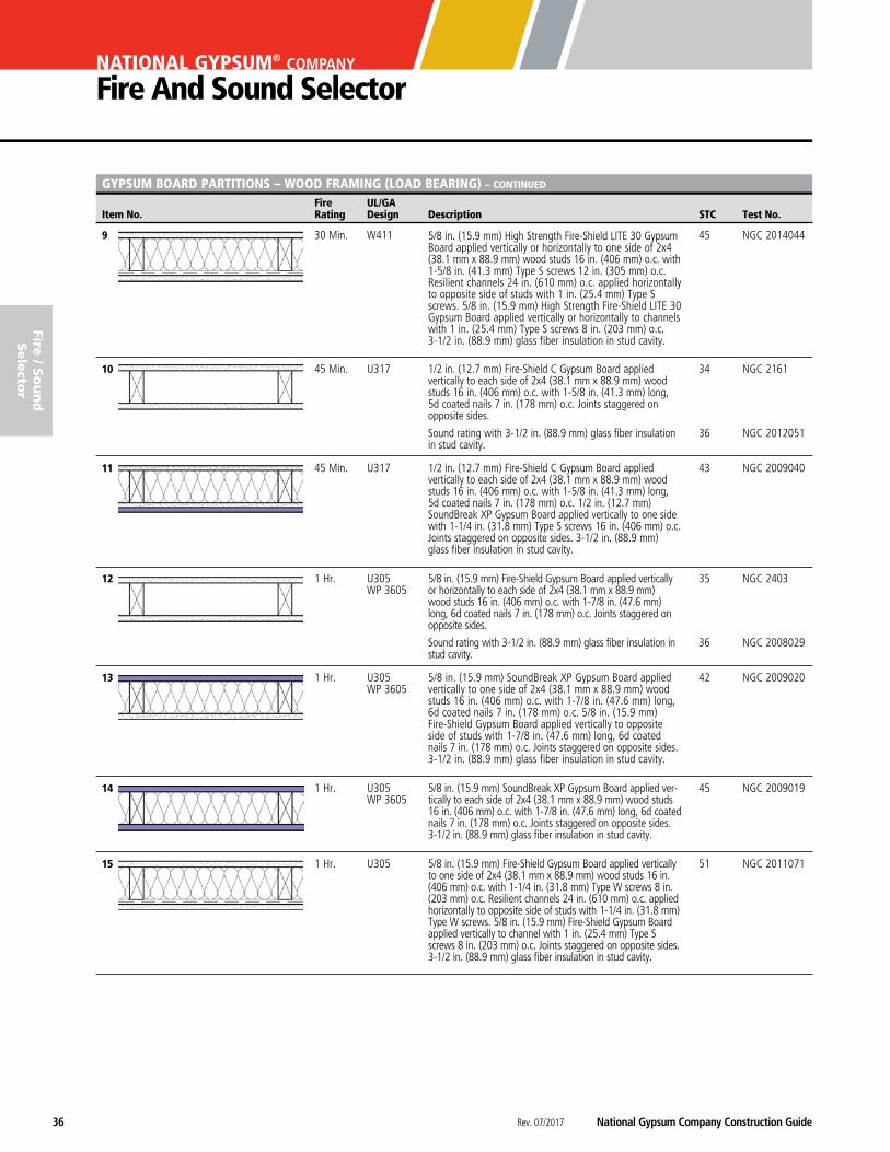
GYPSUM BOARD PARTITIONS – WOOD FRAMING (LOAD BEARING) – CONTINUED
9 30 Min. W411 45 NGC 2014044
10 45 Min. U317 34 NGC 2161 36 NGC 2012051
11 45 Min. U317 43 NGC 2009040
12 1 Hr. U305 35 NGC 2403 WP 3605
36 NGC 2008029
13 1 Hr. U305 42 NGC 2009020 WP 3605
14 1 Hr. U305 45 NGC 2009019 WP 3605
15 1 Hr. U305 51 NGC 2011071
5/8 in. (15.9 mm) High Strength Fire-Shield LITE 30 Gypsum Board applied vertically or horizontally to one side of 2x4 (38.1 mm x 88.9 mm) wood studs 16 in. (406 mm) o.c. with 1-5/8 in. (41.3 mm) Type S screws 12 in. (305 mm) o.c. Resilient channels 24 in. (610 mm) o.c. applied horizontally to opposite side of studs with 1 in. (25.4 mm) Type S screws. 5/8 in. (15.9 mm) High Strength Fire-Shield LITE 30 Gypsum Board applied vertically or horizontally to channels with 1 in. (25.4 mm) Type S screws 8 in. (203 mm) o.c. 3-1/2 in. (88.9 mm) glass fiber insulation in stud cavity.
1/2 in. (12.7 mm) Fire-Shield C Gypsum Board applied vertically to each side of 2x4 (38.1 mm x 88.9 mm) wood studs 16 in. (406 mm) o.c. with 1-5/8 in. (41.3 mm) long, 5d coated nails 7 in. (178 mm) o.c. Joints staggered on opposite sides.
Sound rating with 3-1/2 in. (88.9 mm) glass fiber insulation in stud cavity.
1/2 in. (12.7 mm) Fire-Shield C Gypsum Board applied vertically to each side of 2x4 (38.1 mm x 88.9 mm) wood studs 16 in. (406 mm) o.c. with 1-5/8 in. (41.3 mm) long, 5d coated nails 7 in. (178 mm) o.c. 1/2 in. (12.7 mm) SoundBreak XP Gypsum Board applied vertically to one side with 1-1/4 in. (31.8 mm) Type S screws 16 in. (406 mm) o.c. Joints staggered on opposite sides. 3-1/2 in. (88.9 mm) glass fiber insulation in stud cavity.
5/8 in. (15.9 mm) Fire-Shield Gypsum Board applied vertically or horizontally to each side of 2x4 (38.1 mm x 88.9 mm) wood studs 16 in. (406 mm) o.c. with 1-7/8 in. (47.6 mm) long, 6d coated nails 7 in. (178 mm) o.c. Joints staggered on opposite sides.
Sound rating with 3-1/2 in. (88.9 mm) glass fiber insulation in stud cavity.
5/8 in. (15.9 mm) SoundBreak XP Gypsum Board applied vertically to one side of 2x4 (38.1 mm x 88.9 mm) wood studs 16 in. (406 mm) o.c. with 1-7/8 in. (47.6 mm) long, 6d coated nails 7 in. (178 mm) o.c. 5/8 in. (15.9 mm) Fire-Shield Gypsum Board applied vertically to opposite side of studs with 1-7/8 in. (47.6 mm) long, 6d coated nails 7 in. (178 mm) o.c. Joints staggered on opposite sides. 3-1/2 in. (88.9 mm) glass fiber insulation in stud cavity.
5/8 in. (15.9 mm) SoundBreak XP Gypsum Board applied ver-tically to each side of 2x4 (38.1 mm x 88.9 mm) wood studs 16 in. (406 mm) o.c. with 1-7/8 in. (47.6 mm) long, 6d coated nails 7 in. (178 mm) o.c. Joints staggered on opposite sides. 3-1/2 in. (88.9 mm) glass fiber insulation in stud cavity.
5/8 in. (15.9 mm) Fire-Shield Gypsum Board applied vertically to one side of 2x4 (38.1 mm x 88.9 mm) wood studs 16 in. (406 mm) o.c. with 1-1/4 in. (31.8 mm) Type W screws 8 in. (203 mm) o.c. Resilient channels 24 in. (610 mm) o.c. applied horizontally to opposite side of studs with 1-1/4 in. (31.8 mm) Type W screws. 5/8 in. (15.9 mm) Fire-Shield Gypsum Board applied vertically to channel with 1 in. (25.4 mm) Type S screws 8 in. (203 mm) o.c. Joints staggered on opposite sides. 3-1/2 in. (88.9 mm) glass fiber insulation in stud cavity.
National Gypsum Company Construction Guide Rev. 07/2017 37
fire
/ S
ou
nd
Sele
cto
r
Fire UL/GA Item No. Rating Design Description STC Test No.
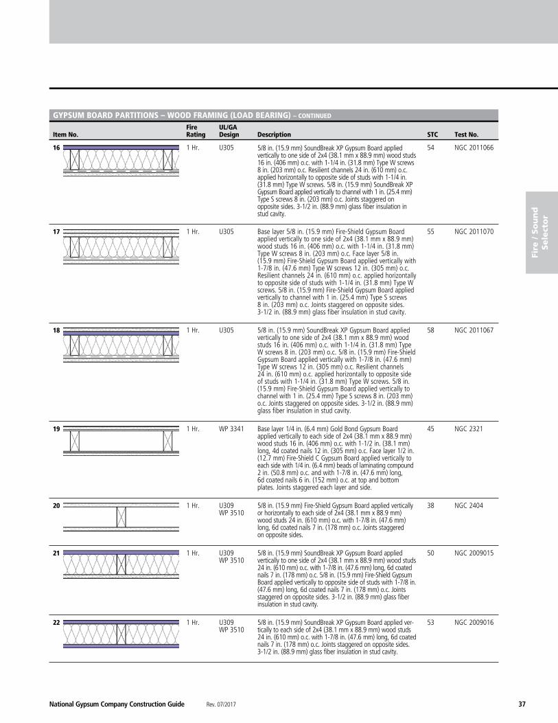
GYPSUM BOARD PARTITIONS – WOOD FRAMING (LOAD BEARING) – CONTINUED
16 1 Hr. U305 54 NGC 2011066
17 1 Hr. U305 55 NGC 2011070
18 1 Hr. U305 58 NGC 2011067
19 1 Hr. WP 3341 45 NGC 2321
20 1 Hr. U309 38 NGC 2404 WP 3510
21 1 Hr. U309 50 NGC 2009015 WP 3510
22 1 Hr. U309 53 NGC 2009016 WP 3510
5/8 in. (15.9 mm) SoundBreak XP Gypsum Board applied vertically to one side of 2x4 (38.1 mm x 88.9 mm) wood studs 16 in. (406 mm) o.c. with 1-1/4 in. (31.8 mm) Type W screws 8 in. (203 mm) o.c. Resilient channels 24 in. (610 mm) o.c. applied horizontally to opposite side of studs with 1-1/4 in. (31.8 mm) Type W screws. 5/8 in. (15.9 mm) SoundBreak XP Gypsum Board applied vertically to channel with 1 in. (25.4 mm) Type S screws 8 in. (203 mm) o.c. Joints staggered on opposite sides. 3-1/2 in. (88.9 mm) glass fiber insulation in stud cavity.
Base layer 5/8 in. (15.9 mm) Fire-Shield Gypsum Board applied vertically to one side of 2x4 (38.1 mm x 88.9 mm) wood studs 16 in. (406 mm) o.c. with 1-1/4 in. (31.8 mm) Type W screws 8 in. (203 mm) o.c. Face layer 5/8 in. (15.9 mm) Fire-Shield Gypsum Board applied vertically with 1-7/8 in. (47.6 mm) Type W screws 12 in. (305 mm) o.c. Resilient channels 24 in. (610 mm) o.c. applied horizontally to opposite side of studs with 1-1/4 in. (31.8 mm) Type W screws. 5/8 in. (15.9 mm) Fire-Shield Gypsum Board applied vertically to channel with 1 in. (25.4 mm) Type S screws 8 in. (203 mm) o.c. Joints staggered on opposite sides. 3-1/2 in. (88.9 mm) glass fiber insulation in stud cavity.
5/8 in. (15.9 mm) SoundBreak XP Gypsum Board applied vertically to one side of 2x4 (38.1 mm x 88.9 mm) wood studs 16 in. (406 mm) o.c. with 1-1/4 in. (31.8 mm) Type W screws 8 in. (203 mm) o.c. 5/8 in. (15.9 mm) Fire-Shield Gypsum Board applied vertically with 1-7/8 in. (47.6 mm) Type W screws 12 in. (305 mm) o.c. Resilient channels 24 in. (610 mm) o.c. applied horizontally to opposite side of studs with 1-1/4 in. (31.8 mm) Type W screws. 5/8 in. (15.9 mm) Fire-Shield Gypsum Board applied vertically to channel with 1 in. (25.4 mm) Type S screws 8 in. (203 mm) o.c. Joints staggered on opposite sides. 3-1/2 in. (88.9 mm) glass fiber insulation in stud cavity.
Base layer 1/4 in. (6.4 mm) Gold Bond Gypsum Board applied vertically to each side of 2x4 (38.1 mm x 88.9 mm) wood studs 16 in. (406 mm) o.c. with 1-1/2 in. (38.1 mm) long, 4d coated nails 12 in. (305 mm) o.c. Face layer 1/2 in. (12.7 mm) Fire-Shield C Gypsum Board applied vertically to each side with 1/4 in. (6.4 mm) beads of laminating compound 2 in. (50.8 mm) o.c. and with 1-7/8 in. (47.6 mm) long, 6d coated nails 6 in. (152 mm) o.c. at top and bottom plates. Joints staggered each layer and side.
5/8 in. (15.9 mm) Fire-Shield Gypsum Board applied vertically or horizontally to each side of 2x4 (38.1 mm x 88.9 mm) wood studs 24 in. (610 mm) o.c. with 1-7/8 in. (47.6 mm) long, 6d coated nails 7 in. (178 mm) o.c. Joints staggered on opposite sides.
5/8 in. (15.9 mm) SoundBreak XP Gypsum Board applied vertically to one side of 2x4 (38.1 mm x 88.9 mm) wood studs 24 in. (610 mm) o.c. with 1-7/8 in. (47.6 mm) long, 6d coated nails 7 in. (178 mm) o.c. 5/8 in. (15.9 mm) Fire-Shield Gypsum Board applied vertically to opposite side of studs with 1-7/8 in. (47.6 mm) long, 6d coated nails 7 in. (178 mm) o.c. Joints staggered on opposite sides. 3-1/2 in. (88.9 mm) glass fiber insulation in stud cavity.
5/8 in. (15.9 mm) SoundBreak XP Gypsum Board applied ver-tically to each side of 2x4 (38.1 mm x 88.9 mm) wood studs 24 in. (610 mm) o.c. with 1-7/8 in. (47.6 mm) long, 6d coated nails 7 in. (178 mm) o.c. Joints staggered on opposite sides. 3-1/2 in. (88.9 mm) glass fiber insulation in stud cavity.
Rev. 07/2017 National Gypsum Company Construction Guide38
NATIONAL GYPSUM® COMPANY
Fire And Sound Selector
Fire UL/GA Item No. Rating Design Description STC Test No.
fire / S
ou
nd
Sele
ctor
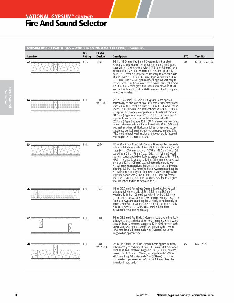
GYPSUM BOARD PARTITIONS – WOOD FRAMING (LOAD BEARING) – CONTINUED
23 1 Hr. U309 50 NRCC TL-93-196
24 1 Hr. U311 WP 3241
25 1 Hr. U344
26 1 Hr. U392
27 1 Hr. U340
28 1 Hr. U340 45 NGC 2375 WP 5513
1/2 in. (12.7 mm) PermaBase Cement Board applied vertically or horizontally to one side of 2x4 (38.1 mm x 88.9 mm) wood studs 16 in. (406 mm) o.c. with 1-1/4 in. (31.8 mm) cement board screws at 8 in. (203 mm) o.c. 5/8 in. (15.9 mm) Fire-Shield Gypsum Board applied vertically or horizontally to opposite side with 1-7/8 in. (47.6 mm) long, 6d coated nails 7 in. (178 mm) o.c. 3 1/2 in. (88.9 mm) mineral fiber insulation friction fit in stud cavity.
5/8 in. (15.9 mm) Fire-Shield C Gypsum Board applied vertically or horizontally to each side of 2x4 (38.1 mm x 88.9 mm) wood studs 24 in. (610 mm) o.c. staggered 12 in. (305 mm) on each side of 2x6 (38.1 mm x 140 mm) wood plate with 1-7/8 in. (47.6 mm) long, 6d coated nails 7 in. (178 mm) o.c. Joints staggered on opposite sides.
5/8 in. (15.9 mm) Fire-Shield Gypsum Board applied vertically or horizontally to each side of 2x4 (38.1 mm x 88.9 mm) wood studs 16 in. (406 mm) o.c. staggered 8 in. (203 mm) on each side of 2x6 (38.1 mm x 140 mm) wood plate with 1-7/8 in. (47.6 mm) long, 6d coated nails 7 in. (178 mm) o.c. Joints staggered on opposite sides. 3-1/2 in. (88.9 mm) glass fiber insulation in stud cavity.
5/8 in. (15.9 mm) Fire-Shield Gypsum Board applied vertically or horizontally to one side of 2x4 (38.1 mm x 88.9 mm) wood studs 24 in. (610 mm) o.c. with 1-7/8 in. (47.6 mm) long, 6d coated nails 7 in. (178 mm) o.c. 15/32 in. (11.9 mm) wood structural panels applied vertically to opposite side with 1-7/8 in. (47.6 mm) long, 6d coated nails 6 in. (152 mm) o.c. at vertical joints and 12 in. (305 mm) o.c. at intermediate studs with vertical joints staggered and horizontal joints backed by wood blocking. 5/8 in. (15.9 mm) Fire-Shield Gypsum Board applied vertically or horizontally and fastened to studs through wood structural panels with 2-3/8 in. (60.3 mm) long, 8d coated nails 7 in. (178 mm) o.c. 3-1/2 in. (88.9 mm) foil-faced glass fiber insulation friction fit between studs.
5/8 in. (15.9 mm) Fire-Shield C Gypsum Board applied horizontally to one side of 2x4 (38.1 mm x 88.9 mm) wood studs 24 in. (610 mm) o.c. with 1-1/4 in. (31.8 mm) Type W screws 12 in. (305 mm) o.c. Resilient channels 24 in. (610 mm) o.c. applied horizontally to opposite side of studs with 1-1/4 in. (31.8 mm) Type W screws. 5/8 in. (15.9 mm) Fire-Shield C Gypsum Board applied horizontally to channel with 1 in. (25.4 mm) Type S screws 12 in. (305 mm) o.c. Vertical joints located between studs and back-blocked with 20 in. (508 mm) long resilient channel. Horizontal joints not required to be staggered. Vertical joints staggered on opposite sides. 3 in. (76.2 mm) mineral wool insulation between studs fastened with staples 24 in. (610 mm) o.c.
5/8 in. (15.9 mm) Fire-Shield Gypsum Board applied vertically to one side of 2x4 (38.1 mm x 88.9 mm) wood studs 24 in. (610 mm) o.c. with 1-7/8 in. (47.6 mm) long, 6d coated nails 7 in. (178 mm) o.c. Resilient channels 24 in. (610 mm) o.c. applied horizontally to opposite side of studs with 1-1/4 in. (31.8 mm) Type W screws. 5/8 in. (15.9 mm) Fire-Shield Gypsum Board applied vertically to channel with 1 in. (25.4 mm) Type S screws 8 in. (203 mm) o.c. 3 in. (76.2 mm) glass fiber insulation between studs fastened with staples 24 in. (610 mm) o.c. Joints staggered on opposite sides.
National Gypsum Company Construction Guide Rev. 07/2017 39
fire
/ S
ou
nd
Sele
cto
r
Fire UL/GA Item No. Rating Design Description STC Test No.
GYPSUM BOARD PARTITIONS – WOOD FRAMING (LOAD BEARING) – CONTINUED
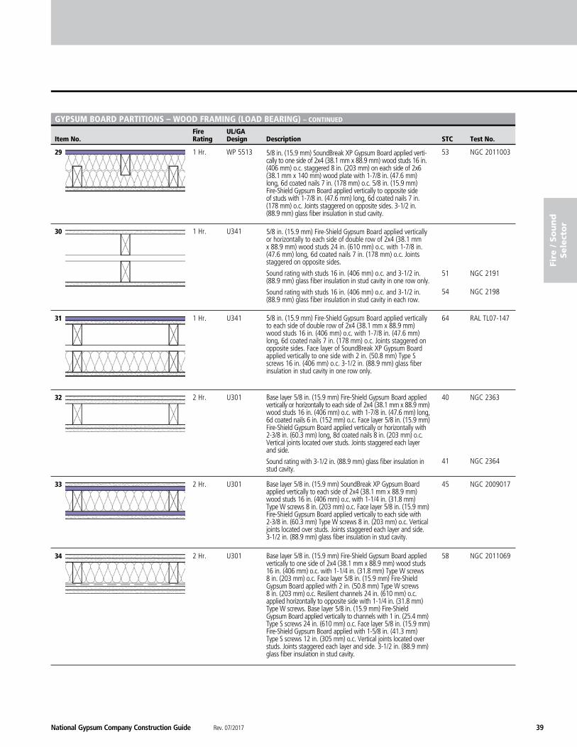
29 1 Hr. WP 5513 53 NGC 2011003
30 1 Hr. U341
51 NGC 2191 54 NGC 2198
31 1 Hr. U341 64 RAL TL07-147
32 2 Hr. U301 40 NGC 2363 41 NGC 2364
33 2 Hr. U301 45 NGC 2009017
34 2 Hr. U301 58 NGC 2011069
5/8 in. (15.9 mm) SoundBreak XP Gypsum Board applied verti-cally to one side of 2x4 (38.1 mm x 88.9 mm) wood studs 16 in. (406 mm) o.c. staggered 8 in. (203 mm) on each side of 2x6 (38.1 mm x 140 mm) wood plate with 1-7/8 in. (47.6 mm) long, 6d coated nails 7 in. (178 mm) o.c. 5/8 in. (15.9 mm) Fire-Shield Gypsum Board applied vertically to opposite side of studs with 1-7/8 in. (47.6 mm) long, 6d coated nails 7 in. (178 mm) o.c. Joints staggered on opposite sides. 3-1/2 in. (88.9 mm) glass fiber insulation in stud cavity.
5/8 in. (15.9 mm) Fire-Shield Gypsum Board applied vertically or horizontally to each side of double row of 2x4 (38.1 mm x 88.9 mm) wood studs 24 in. (610 mm) o.c. with 1-7/8 in. (47.6 mm) long, 6d coated nails 7 in. (178 mm) o.c. Joints staggered on opposite sides.
Sound rating with studs 16 in. (406 mm) o.c. and 3-1/2 in. (88.9 mm) glass fiber insulation in stud cavity in one row only.
Sound rating with studs 16 in. (406 mm) o.c. and 3-1/2 in. (88.9 mm) glass fiber insulation in stud cavity in each row.
5/8 in. (15.9 mm) Fire-Shield Gypsum Board applied vertically to each side of double row of 2x4 (38.1 mm x 88.9 mm) wood studs 16 in. (406 mm) o.c. with 1-7/8 in. (47.6 mm) long, 6d coated nails 7 in. (178 mm) o.c. Joints staggered on opposite sides. Face layer of SoundBreak XP Gypsum Board applied vertically to one side with 2 in. (50.8 mm) Type S screws 16 in. (406 mm) o.c. 3-1/2 in. (88.9 mm) glass fiber insulation in stud cavity in one row only.
Base layer 5/8 in. (15.9 mm) Fire-Shield Gypsum Board applied vertically or horizontally to each side of 2x4 (38.1 mm x 88.9 mm) wood studs 16 in. (406 mm) o.c. with 1-7/8 in. (47.6 mm) long, 6d coated nails 6 in. (152 mm) o.c. Face layer 5/8 in. (15.9 mm) Fire-Shield Gypsum Board applied vertically or horizontally with 2-3/8 in. (60.3 mm) long, 8d coated nails 8 in. (203 mm) o.c. Vertical joints located over studs. Joints staggered each layer and side.
Sound rating with 3-1/2 in. (88.9 mm) glass fiber insulation in stud cavity.
Base layer 5/8 in. (15.9 mm) SoundBreak XP Gypsum Board applied vertically to each side of 2x4 (38.1 mm x 88.9 mm) wood studs 16 in. (406 mm) o.c. with 1-1/4 in. (31.8 mm) Type W screws 8 in. (203 mm) o.c. Face layer 5/8 in. (15.9 mm) Fire-Shield Gypsum Board applied vertically to each side with 2-3/8 in. (60.3 mm) Type W screws 8 in. (203 mm) o.c. Vertical joints located over studs. Joints staggered each layer and side. 3-1/2 in. (88.9 mm) glass fiber insulation in stud cavity.
Base layer 5/8 in. (15.9 mm) Fire-Shield Gypsum Board applied vertically to one side of 2x4 (38.1 mm x 88.9 mm) wood studs 16 in. (406 mm) o.c. with 1-1/4 in. (31.8 mm) Type W screws 8 in. (203 mm) o.c. Face layer 5/8 in. (15.9 mm) Fire-Shield Gypsum Board applied with 2 in. (50.8 mm) Type W screws 8 in. (203 mm) o.c. Resilient channels 24 in. (610 mm) o.c. applied horizontally to opposite side with 1-1/4 in. (31.8 mm) Type W screws. Base layer 5/8 in. (15.9 mm) Fire-Shield Gypsum Board applied vertically to channels with 1 in. (25.4 mm) Type S screws 24 in. (610 mm) o.c. Face layer 5/8 in. (15.9 mm) Fire-Shield Gypsum Board applied with 1-5/8 in. (41.3 mm) Type S screws 12 in. (305 mm) o.c. Vertical joints located over studs. Joints staggered each layer and side. 3-1/2 in. (88.9 mm) glass fiber insulation in stud cavity.
Rev. 07/2017 National Gypsum Company Construction Guide40
NATIONAL GYPSUM® COMPANY
Fire And Sound Selector
Fire UL/GA Item No. Rating Design Description STC Test No.
fire / S
ou
nd
Sele
ctor
GYPSUM BOARD PARTITIONS – WOOD FRAMING (LOAD BEARING) – CONTINUED
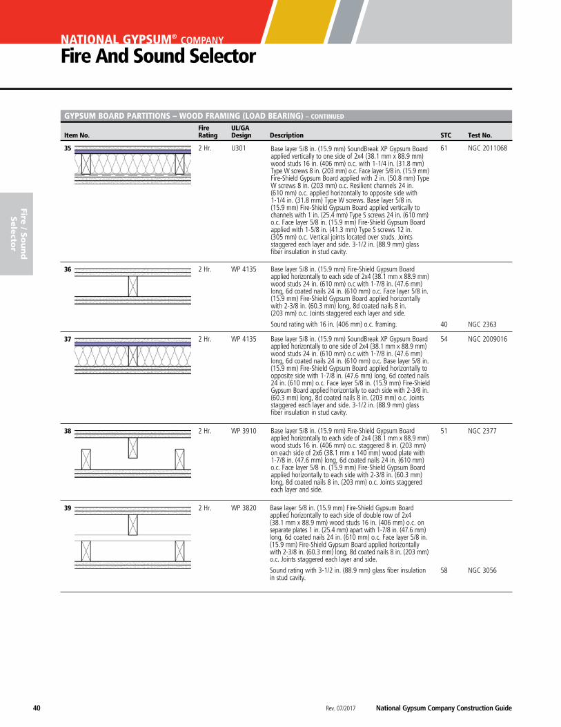
35 2 Hr. U301 61 NGC 2011068
36 2 Hr. WP 4135
40 NGC 2363
37 2 Hr. WP 4135 54 NGC 2009016
38 2 Hr. WP 3910 51 NGC 2377
39 2 Hr. WP 3820
58 NGC 3056
Base layer 5/8 in. (15.9 mm) SoundBreak XP Gypsum Board applied vertically to one side of 2x4 (38.1 mm x 88.9 mm) wood studs 16 in. (406 mm) o.c. with 1-1/4 in. (31.8 mm) Type W screws 8 in. (203 mm) o.c. Face layer 5/8 in. (15.9 mm) Fire-Shield Gypsum Board applied with 2 in. (50.8 mm) Type W screws 8 in. (203 mm) o.c. Resilient channels 24 in. (610 mm) o.c. applied horizontally to opposite side with 1-1/4 in. (31.8 mm) Type W screws. Base layer 5/8 in. (15.9 mm) Fire-Shield Gypsum Board applied vertically to channels with 1 in. (25.4 mm) Type S screws 24 in. (610 mm) o.c. Face layer 5/8 in. (15.9 mm) Fire-Shield Gypsum Board applied with 1-5/8 in. (41.3 mm) Type S screws 12 in. (305 mm) o.c. Vertical joints located over studs. Joints staggered each layer and side. 3-1/2 in. (88.9 mm) glass fiber insulation in stud cavity.
Base layer 5/8 in. (15.9 mm) Fire-Shield Gypsum Board applied horizontally to each side of 2x4 (38.1 mm x 88.9 mm) wood studs 24 in. (610 mm) o.c with 1-7/8 in. (47.6 mm) long, 6d coated nails 24 in. (610 mm) o.c. Face layer 5/8 in. (15.9 mm) Fire-Shield Gypsum Board applied horizontally with 2-3/8 in. (60.3 mm) long, 8d coated nails 8 in. (203 mm) o.c. Joints staggered each layer and side.
Sound rating with 16 in. (406 mm) o.c. framing.
Base layer 5/8 in. (15.9 mm) SoundBreak XP Gypsum Board applied horizontally to one side of 2x4 (38.1 mm x 88.9 mm) wood studs 24 in. (610 mm) o.c with 1-7/8 in. (47.6 mm) long, 6d coated nails 24 in. (610 mm) o.c. Base layer 5/8 in. (15.9 mm) Fire-Shield Gypsum Board applied horizontally to opposite side with 1-7/8 in. (47.6 mm) long, 6d coated nails 24 in. (610 mm) o.c. Face layer 5/8 in. (15.9 mm) Fire-Shield Gypsum Board applied horizontally to each side with 2-3/8 in. (60.3 mm) long, 8d coated nails 8 in. (203 mm) o.c. Joints staggered each layer and side. 3-1/2 in. (88.9 mm) glass fiber insulation in stud cavity.
Base layer 5/8 in. (15.9 mm) Fire-Shield Gypsum Board applied horizontally to each side of 2x4 (38.1 mm x 88.9 mm) wood studs 16 in. (406 mm) o.c. staggered 8 in. (203 mm) on each side of 2x6 (38.1 mm x 140 mm) wood plate with 1-7/8 in. (47.6 mm) long, 6d coated nails 24 in. (610 mm) o.c. Face layer 5/8 in. (15.9 mm) Fire-Shield Gypsum Board applied horizontally to each side with 2-3/8 in. (60.3 mm) long, 8d coated nails 8 in. (203 mm) o.c. Joints staggered each layer and side.
Base layer 5/8 in. (15.9 mm) Fire-Shield Gypsum Board applied horizontally to each side of double row of 2x4 (38.1 mm x 88.9 mm) wood studs 16 in. (406 mm) o.c. on separate plates 1 in. (25.4 mm) apart with 1-7/8 in. (47.6 mm) long, 6d coated nails 24 in. (610 mm) o.c. Face layer 5/8 in. (15.9 mm) Fire-Shield Gypsum Board applied horizontally with 2-3/8 in. (60.3 mm) long, 8d coated nails 8 in. (203 mm) o.c. Joints staggered each layer and side.
Sound rating with 3-1/2 in. (88.9 mm) glass fiber insulation in stud cavity.
National Gypsum Company Construction Guide Rev. 07/2017 41
fire
/ S
ou
nd
Sele
cto
r
Fire UL/GA Item No. Rating Design Description STC Test No.
GYPSUM BOARD PARTITIONS – WOOD FRAMING (LOAD BEARING) – EXTERIOR WALLS
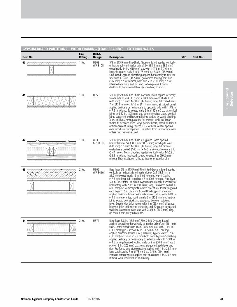
40 1 Hr. U309 WP 8105
41 1 Hr. U356
42 1 Hr. WHI 651-0319
43 2 Hr. U302 WP 8410
44 2 Hr. U371
5/8 in. (15.9 mm) Fire-Shield Gypsum Board applied vertically or horizontally to interior side of 2x4 (38.1 mm x 88.9 mm) wood studs 24 in. (610 mm) o.c. with 1-7/8 in. (47.6 mm) long, 6d coated nails 7 in. (178 mm) o.c. 5/8 in. (15.9 mm) Gold Bond Gypsum Sheathing applied horizontally to exterior side with 1-3/4 in. (44.5 mm) galvanized roofing nails 4 in. (102 mm) o.c. at vertical joints and 7 in. (178 mm) o.c. at intermediate studs and top and bottom plates. Exterior cladding to be fastened through sheathing to studs.
5/8 in. (15.9 mm) Fire-Shield Gypsum Board applied vertically to one side of 2x4 (38.1 mm x 88.9 mm) wood studs 16 in. (406 mm) o.c. with 1-7/8 in. (47.6 mm) long, 6d coated nails 7 in. (178 mm) o.c. 7/16 in. (11.1 mm) wood structural panels applied vertically or horizontally to opposite side with 1-7/8 in. (47.6 mm) long, 6d coated nails 6 in. (152 mm) o.c. at vertical joints and 12 in. (305 mm) o.c. at intermediate studs. Vertical joints staggered and horizontal joints backed by wood blocking. 3-1/2 in. (88.9 mm) glass fiber or mineral wool insulation friction fit between studs. Vinyl, particle board, wood, aluminum or fiber-cement siding, stucco, EIFS, or brick veneer applied over wood structural panels. Fire rating from interior side only unless brick veneer is used.
5/8 in. (15.9 mm) Fire-Shield C Gypsum Board applied horizontally to 2x4 (38.1 mm x 88.9 mm) wood girts 24 in. (610 mm) o.c. with 1-7/8 in. (47.6 mm) long, 6d cement-coated nails on 6x6 (140 mm x 140 mm) wood columns 8 ft. (2.44 m) o.c. Metal cladding applied vertically with 1-1/2 in. (38.1 mm) long hex-head screws to girts. 3 in. (76.2 mm) mineral fiber insulation nailed to interior of exterior girts.
Base layer 5/8 in. (15.9 mm) Fire-Shield Gypsum Board applied vertically or horizontally to interior side of 2x4 (38.1 mm x 88.9 mm) wood studs 16 in. (406 mm) o.c. with 1-7/8 in. (47.6 mm) long, 6d coated nails 8 in. (203 mm) o.c. Face layer 5/8 in. (15.9 mm) Fire-Shield Gypsum Board applied vertically or horizontally with 2-3/8 in. (60.3 mm) long, 8d coated nails 8 in. (203 mm) o.c. Vertical joints located over studs. Joints staggered each layer. 1/2 in. (12.7 mm) Gold Bond Gypsum Sheathing applied horizontally to exterior side of wood studs with 1-3/4 in. (44.5 mm) galvanized roofing nails 6 in. (152 mm) o.c. Vertical joints located over studs and staggered between adjacent rows. Exterior clay brick veneer with 1 in. (25.4 mm) air space between brick and exterior sheathing and 20-gauge corrugated wall ties fastened to each stud with 2-3/8 in. (60.3 mm) long, 8d coated nails every 6th course.
Base layer 5/8 in. (15.9 mm) Fire-Shield Gypsum Board applied vertically or horizontally to interior side of 2x4 (38.1 mm x 88.9 mm) wood studs 16 in. (406 mm) o.c. with 1-1/4 in. (31.8 mm) type S screws 12 in. (305 mm) o.c. Face layer applied horizontally with 2 in. (50.8 mm) Type S screws 12 in. (305 mm) o.c. 5/8 in. (15.9 mm) Gold Bond Gypsum Sheathing applied vertically or horizontally to exterior side with 1-3/4 in. (44.5 mm) galvanized roofing nails or 2 in. (50.8 mm) Type S screws, 8 in. (203 mm) o.c. Joints staggered each layer and side. Pre-furred wire stucco netting applied with 1 in. (25.4 mm) long steel staples 7 in. (178 mm) o.c. 3/4 in. (19.1 mm) Portland cement stucco applied over stucco net. 3 in. (76.2 mm) mineral wool insulation in stud cavity.
Rev. 07/2017 National Gypsum Company Construction Guide42
NATIONAL GYPSUM® COMPANY
Fire And Sound Selector
Fire UL/GA Item No. Rating Design Description STC Test No.
fire / S
ou
nd
Sele
ctor
GYPSUM BOARD PARTITIONS – STEEL FRAMING (NON-LOAD BEARING)
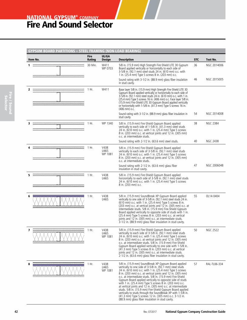
1 30 Min. W411 36 NGC 2014006 WP 0703 46 NGC 2015005
2 1 Hr. W411 54 NGC 2014008
3 1 Hr. WP 1340 38 NGC 2384
40 NGC 2438
4 1 Hr. V438 U465 WP 1081
47 NGC 2006048
5 1 Hr. V438 U465
6 1 Hr. V438 55 OL14-0404 U465
7 1 Hr. V438 50 NGC 2522 U465 WP 1081
8 1 Hr. V438 57 RAL-TL06-334 U465 WP 1081
5/8 in. (15.9 mm) High Strength Fire-Shield LITE 30 Gypsum Board applied vertically or horizontally to each side of 3-5/8 in. (92.1 mm) steel studs 24 in. (610 mm) o.c. with 1 in. (25.4 mm) Type S screws 8 in. (203 mm) o.c.
Sound rating with 3-1/2 in. (88.9 mm) glass fiber insulation in stud cavity.
Base layer 5/8 in. (15.9 mm) High Strength Fire-Shield LITE 30 Gypsum Board applied vertically or horizontally to each side of 3-5/8 in. (92.1 mm) steel studs 24 in. (610 mm) o.c. with 1 in. (25.4 mm) Type S screws 16 in. (406 mm) o.c. Face layer 5/8 in. (15.9 mm) Fire-Shield LITE 30 Gypsum Board applied vertically or horizontally with 1-5/8 in. (41.3 mm) Type S screws 16 in. (406 mm) o.c.
Sound rating with 3-1/2 in. (88.9 mm) glass fiber insulation in stud cavity.
5/8 in. (15.9 mm) Fire-Shield Gypsum Board applied vertically to each side of 1-5/8 in. (41.3 mm) steel studs 24 in. (610 mm) o.c. with 1 in. (25.4 mm) Type S screws 8 in. (203 mm) o.c. at vertical joints and 12 in. (305 mm) o.c. at intermediate studs.
Sound rating with 2-1/2 in. (63.6 mm) steel studs.
5/8 in. (15.9 mm) Fire-Shield Gypsum Board applied vertically to each side of 3-5/8 in. (92.1 mm) steel studs 24 in. (610 mm) o.c. with 1 in. (25.4 mm) Type S screws 8 in. (203 mm) o.c. at vertical joints and 12 in. (305 mm) o.c. at intermediate studs.
Sound rating with 2-1/2 in. (63.6 mm) glass fiber insulation in stud cavity.
5/8 in. (15.9 mm) Fire-Shield Gypsum Board applied horizontally to each side of 3-5/8 in. (92.1 mm) steel studs 24 in. (610 mm) o.c. with 1 in. (25.4 mm) Type S screws 8 in. (203 mm) o.c.
5/8 in. (15.9 mm) SoundBreak XP Gypsum Board applied vertically to one side of 3-5/8 in. (92.1 mm) steel studs 24 in. (610 mm) o.c. with 1 in. (25.4 mm) Type S screws 8 in. (203 mm) o.c. at vertical joints and 12 in. (305 mm) o.c. at intermediate studs. 5/8 in. (15.9 mm) Fire-Shield Gypsum Board applied vertically to opposite side of studs with 1 in. (25.4 mm) Type S screws 8 in. (203 mm) o.c. at vertical joints and 12 in. (305 mm) o.c. at intermediate studs. 3-1/2 in. (88.9 mm) glass fiber insulation in stud cavity.
5/8 in. (15.9 mm) Fire-Shield Gypsum Board applied vertically to each side of 3-5/8 in. (92.1 mm) steel studs 24 in. (610 mm) o.c. with 1 in. (25.4 mm) Type S screws 8 in. (203 mm) o.c. at vertical joints and 12 in. (305 mm) o.c. at intermediate studs. 5/8 in. (15.9 mm) Fire-Shield Gypsum Board applied vertically to one side with 1-5/8 in. (41.3 mm) Type S screws 8 in. (203 mm) o.c. at vertical joints and 12 in. (305 mm) o.c. at intermediate studs. 2-1/2 in. (63.6 mm) glass fiber insulation in stud cavity.
5/8 in. (15.9 mm) SoundBreak XP Gypsum Board applied vertically to one side of 3-5/8 in. (92.1 mm) steel studs 24 in. (610 mm) o.c. with 1 in. (25.4 mm) Type S screws 8 in. (203 mm) o.c. at vertical joints and 12 in. (305 mm) o.c. at intermediate studs. 5/8 in. (15.9 mm) Fire-Shield Gypsum Board applied vertically to opposite side of studs with 1 in. (25.4 mm) Type S screws 8 in. (203 mm) o.c. at vertical joints and 12 in. (305 mm) o.c. at intermediate studs. 5/8 in. (15.9 mm) Fire-Shield Gypsum Board applied vertically to studs through the SoundBreak XP with 1-5/8 in. (41.3 mm) Type S screws 12 in. (305 mm) o.c. 3-1/2 in. (88.9 mm) glass fiber insulation in stud cavity.
National Gypsum Company Construction Guide Rev. 07/2017 43
fire
/ S
ou
nd
Sele
cto
r
Fire UL/GA Item No. Rating Design Description STC Test No.
GYPSUM BOARD PARTITIONS – STEEL FRAMING (NON-LOAD BEARING) – CONTINUED
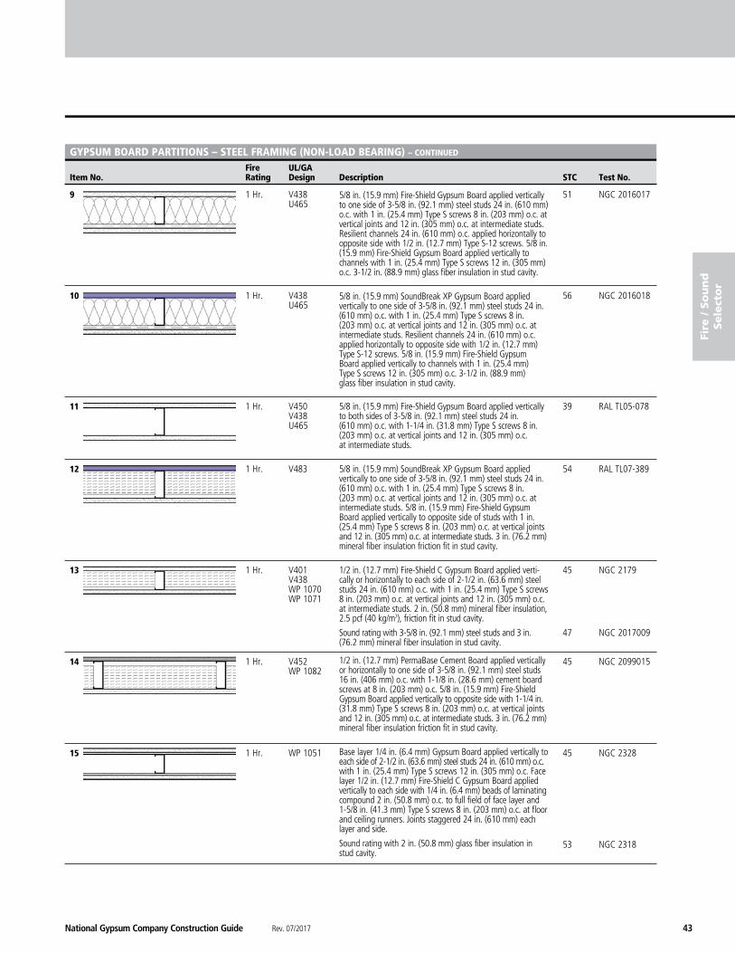
9 1 Hr. V438 51 NGC 2016017 U465
10 1 Hr. V438 56 NGC 2016018 U465
11 1 Hr. V450 39 RAL TL05-078 V438 U465
12 1 Hr. V483 54 RAL TL07-389
13 1 Hr. V401 45 NGC 2179 V438 WP 1070 WP 1071 47 NGC 2017009
14 1 Hr. V452 45 NGC 2099015 WP 1082
15 1 Hr. WP 1051 45 NGC 2328
53 NGC 2318
5/8 in. (15.9 mm) Fire-Shield Gypsum Board applied vertically to one side of 3-5/8 in. (92.1 mm) steel studs 24 in. (610 mm) o.c. with 1 in. (25.4 mm) Type S screws 8 in. (203 mm) o.c. at vertical joints and 12 in. (305 mm) o.c. at intermediate studs. Resilient channels 24 in. (610 mm) o.c. applied horizontally to opposite side with 1/2 in. (12.7 mm) Type S-12 screws. 5/8 in. (15.9 mm) Fire-Shield Gypsum Board applied vertically to channels with 1 in. (25.4 mm) Type S screws 12 in. (305 mm) o.c. 3-1/2 in. (88.9 mm) glass fiber insulation in stud cavity.
5/8 in. (15.9 mm) SoundBreak XP Gypsum Board applied vertically to one side of 3-5/8 in. (92.1 mm) steel studs 24 in. (610 mm) o.c. with 1 in. (25.4 mm) Type S screws 8 in. (203 mm) o.c. at vertical joints and 12 in. (305 mm) o.c. at intermediate studs. Resilient channels 24 in. (610 mm) o.c. applied horizontally to opposite side with 1/2 in. (12.7 mm) Type S-12 screws. 5/8 in. (15.9 mm) Fire-Shield Gypsum Board applied vertically to channels with 1 in. (25.4 mm) Type S screws 12 in. (305 mm) o.c. 3-1/2 in. (88.9 mm) glass fiber insulation in stud cavity.
5/8 in. (15.9 mm) Fire-Shield Gypsum Board applied vertically to both sides of 3-5/8 in. (92.1 mm) steel studs 24 in. (610 mm) o.c. with 1-1/4 in. (31.8 mm) Type S screws 8 in. (203 mm) o.c. at vertical joints and 12 in. (305 mm) o.c. at intermediate studs.
5/8 in. (15.9 mm) SoundBreak XP Gypsum Board applied vertically to one side of 3-5/8 in. (92.1 mm) steel studs 24 in. (610 mm) o.c. with 1 in. (25.4 mm) Type S screws 8 in. (203 mm) o.c. at vertical joints and 12 in. (305 mm) o.c. at intermediate studs. 5/8 in. (15.9 mm) Fire-Shield Gypsum Board applied vertically to opposite side of studs with 1 in. (25.4 mm) Type S screws 8 in. (203 mm) o.c. at vertical joints and 12 in. (305 mm) o.c. at intermediate studs. 3 in. (76.2 mm) mineral fiber insulation friction fit in stud cavity.
1/2 in. (12.7 mm) Fire-Shield C Gypsum Board applied verti-cally or horizontally to each side of 2-1/2 in. (63.6 mm) steel studs 24 in. (610 mm) o.c. with 1 in. (25.4 mm) Type S screws 8 in. (203 mm) o.c. at vertical joints and 12 in. (305 mm) o.c. at intermediate studs. 2 in. (50.8 mm) mineral fiber insulation, 2.5 pcf (40 kg/m3), friction fit in stud cavity.
Sound rating with 3-5/8 in. (92.1 mm) steel studs and 3 in. (76.2 mm) mineral fiber insulation in stud cavity.
1/2 in. (12.7 mm) PermaBase Cement Board applied vertically or horizontally to one side of 3-5/8 in. (92.1 mm) steel studs 16 in. (406 mm) o.c. with 1-1/8 in. (28.6 mm) cement board screws at 8 in. (203 mm) o.c. 5/8 in. (15.9 mm) Fire-Shield Gypsum Board applied vertically to opposite side with 1-1/4 in. (31.8 mm) Type S screws 8 in. (203 mm) o.c. at vertical joints and 12 in. (305 mm) o.c. at intermediate studs. 3 in. (76.2 mm) mineral fiber insulation friction fit in stud cavity.
Base layer 1/4 in. (6.4 mm) Gypsum Board applied vertically to each side of 2-1/2 in. (63.6 mm) steel studs 24 in. (610 mm) o.c. with 1 in. (25.4 mm) Type S screws 12 in. (305 mm) o.c. Face layer 1/2 in. (12.7 mm) Fire-Shield C Gypsum Board applied vertically to each side with 1/4 in. (6.4 mm) beads of laminating compound 2 in. (50.8 mm) o.c. to full field of face layer and 1-5/8 in. (41.3 mm) Type S screws 8 in. (203 mm) o.c. at floor and ceiling runners. Joints staggered 24 in. (610 mm) each layer and side.
Sound rating with 2 in. (50.8 mm) glass fiber insulation in stud cavity.
Rev. 07/2017 National Gypsum Company Construction Guide44
NATIONAL GYPSUM® COMPANY
Fire And Sound Selector
Fire UL/GA Item No. Rating Design Description STC Test No.
fire / S
ou
nd
Sele
ctor
GYPSUM BOARD PARTITIONS – STEEL FRAMING (NON-LOAD BEARING) – CONTINUED
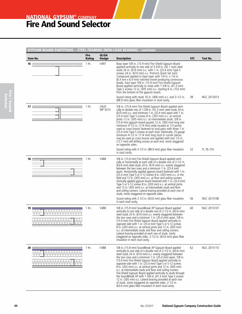
16 1 Hr. V497
38 NGC 2013013
17 1 Hr. U420 WP 5015
52 TL 76-155
18 1 Hr. V488
56 NGC 2015108
19 1 Hr. V488 60 NGC 2015107
20 1 Hr. V488 62 NGC 2015110
Base layer 5/8 in. (15.9 mm) Fire Shield Gypsum Board applied vertically to one side of 3-5/8 in. (92.1 mm) steel studs 24 in. (610 mm) o.c. with 1 in. (25.4 mm) Type S screws 24 in. (610 mm) o.c. ProForm Quick Set Joint Compound applied to base layer with 1/4 in. x 1/4 in. (6.4 mm x 6.4 mm) notched trowel producing continuous beads. Face layer 5/8 in. (15.9 mm) Fire-Shield Gypsum Board applied vertically to studs with 1-5/8 in. (41.3 mm) Type S screws 12 in. (305 mm) o.c. starting 6 in. (152 mm) from the bottom of the gypsum board.
Sound rating with studs 16 in. (406 mm) o.c. and 3-1/2 in. (88.9 mm) glass fiber insulation in stud cavity.
5/8 in. (15.9 mm) Fire-Shield Gypsum Board applied verti-cally to double row of 1-5/8 in. (41.3 mm) steel studs 24 in. (610 mm) o.c. and minimum 1 in. (25.4 mm) apart with 1 in. (25.4 mm) Type S screws 8 in. (203 mm) o.c. at vertical joints 12 in. (305 mm) o.c. at intermediate studs. 5/8 in. (15.9 mm) gypsum board gussets 12 in. (305 mm) long and minimum 4-1/2 in. (114 mm) wide located at 1/3 points used as cross braces fastened to stud pairs with three 1 in. (25.4 mm) Type S screws at each stud. Optionally, 25-gauge minimum 4-1/2 in. (114 mm) long stud or runner pieces may be used as cross braces and applied with two 1/2 in. (12.7 mm) self-drilling screws at each end. Joints staggered on opposite sides.
Sound rating with 3-1/2 in. (88.9 mm) glass fiber insulation in stud cavity.
5/8 in. (15.9 mm) Fire-Shield Gypsum Board applied verti-cally or horizontally to each side of a double row of 2-1/2 in. (63.6 mm) steel studs 24 in. (610 mm) o.c. evenly staggered between the two rows and a minimum 1 in. (25.4 mm) apart. Horizontally applied gypsum board fastened with 1 in. (25.4 mm) Type S or S-12 screws 8 in. (203 mm) o.c. in the field and 12 in. (305 mm) o.c. at floor and ceiling runners. Vertically applied gypsum board fastened with 1 in. (25.4 mm) Type S or S-12 screws 8 in. (203 mm) o.c. at vertical joints and 12 in. (305 mm) o.c. at intermediate studs and floor and ceiling runners. Lateral bracing provided at each row of studs. Joints staggered on opposite sides.
Sound rating with 2-1/2 in. (63.6 mm) glass fiber insulation in each stud cavity.
5/8 in. (15.9 mm) SoundBreak XP Gypsum Board applied vertically to one side of a double row of 2-1/2 in. (63.6 mm) steel studs 24 in. (610 mm) o.c. evenly staggered between the two rows and a minimum 1 in. (25.4 mm) apart. 5/8 in. (15.9 mm) Fire-Shield Gypsum Board applied vertically to opposite side with 1 in. (25.4 mm) Type S or S-12 screws 8 in. (203 mm) o.c. at vertical joints and 12 in. (305 mm) o.c. at intermediate studs and floor and ceiling runners. Lateral bracing provided at each row of studs. Joints staggered on opposite sides. 2-1/2 in. (63.6 mm) glass fiber insulation in each stud cavity.
5/8 in. (15.9 mm) SoundBreak XP Gypsum Board applied vertically to one side of a double row of 2-1/2 in. (63.6 mm) steel studs 24 in. (610 mm) o.c. evenly staggered between the two rows and a minimum 1 in. (25.4 mm) apart. 5/8 in. (15.9 mm) Fire-Shield Gypsum Board applied vertically to opposite side with 1 in. (25.4 mm) Type S or S-12 screws 8 in. (203 mm) o.c. at vertical joints and 12 in. (305 mm) o.c. at intermediate studs and floor and ceiling runners. Fire-Shield Gypsum Board applied vertically to studs through the SoundBreak XP with 1-5/8 in. (41.3 mm) Type S screws 12 in. (305 mm) o.c. Lateral bracing provided at each row of studs. Joints staggered on opposite sides. 2-1/2 in. (63.6 mm) glass fiber insulation in each stud cavity.
National Gypsum Company Construction Guide Rev. 07/2017 45
fire
/ S
ou
nd
Sele
cto
r
Fire UL/GA Item No. Rating Design Description STC Test No.
GYPSUM BOARD PARTITIONS – STEEL FRAMING (NON-LOAD BEARING) – CONTINUED
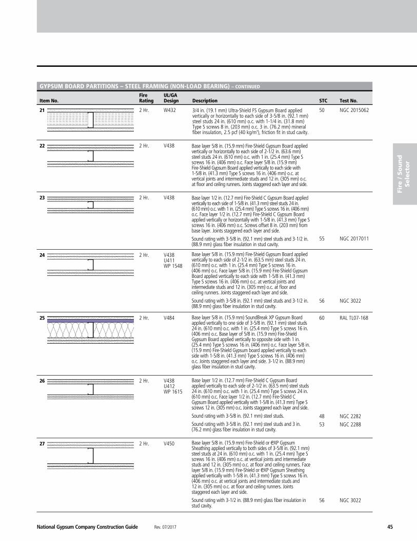
21 2 Hr. W432 50 NGC 2015062
22 2 Hr. V438
23 2 Hr. V438 55 NGC 2017011
24 2 Hr. V438 U411 WP 1548 56 NGC 3022
25 2 Hr. V484 60 RAL TL07-168
26 2 Hr. V438 U412 WP 1615
48 NGC 2282 53 NGC 2288
27 2 Hr. V450 56 NGC 3022
3/4 in. (19.1 mm) Ultra-Shield FS Gypsum Board applied vertically or horizontally to each side of 3-5/8 in. (92.1 mm) steel studs 24 in. (610 mm) o.c. with 1-1/4 in. (31.8 mm) Type S screws 8 in. (203 mm) o.c. 3 in. (76.2 mm) mineral fiber insulation, 2.5 pcf (40 kg/m3), friction fit in stud cavity.
Base layer 5/8 in. (15.9 mm) Fire-Shield Gypsum Board applied vertically or horizontally to each side of 2-1/2 in. (63.6 mm) steel studs 24 in. (610 mm) o.c. with 1 in. (25.4 mm) Type S screws 16 in. (406 mm) o.c. Face layer 5/8 in. (15.9 mm) Fire-Shield Gypsum Board applied vertically to each side with 1-5/8 in. (41.3 mm) Type S screws 16 in. (406 mm) o.c. at vertical joints and intermediate studs and 12 in. (305 mm) o.c. at floor and ceiling runners. Joints staggered each layer and side.
Base layer 1/2 in. (12.7 mm) Fire-Shield C Gypsum Board applied vertically to each side of 1-5/8 in. (41.3 mm) steel studs 24 in. (610 mm) o.c. with 1 in. (25.4 mm) Type S screws 16 in. (406 mm) o.c. Face layer 1/2 in. (12.7 mm) Fire-Shield C Gypsum Board applied vertically or horizontally with 1-5/8 in. (41.3 mm) Type S screws 16 in. (406 mm) o.c. Screws offset 8 in. (203 mm) from base layer. Joints staggered each layer and side.
Sound rating with 3-5/8 in. (92.1 mm) steel studs and 3-1/2 in. (88.9 mm) glass fiber insulation in stud cavity.
Base layer 5/8 in. (15.9 mm) Fire-Shield Gypsum Board applied vertically to each side of 2-1/2 in. (63.5 mm) steel studs 24 in. (610 mm) o.c. with 1 in. (25.4 mm) Type S screws 16 in. (406 mm) o.c. Face layer 5/8 in. (15.9 mm) Fire-Shield Gypsum Board applied vertically to each side with 1-5/8 in. (41.3 mm) Type S screws 16 in. (406 mm) o.c. at vertical joints and intermediate studs and 12 in. (305 mm) o.c. at floor and ceiling runners. Joints staggered each layer and side.
Sound rating with 3-5/8 in. (92.1 mm) steel studs and 3-1/2 in. (88.9 mm) glass fiber insulation in stud cavity.
Base layer 5/8 in. (15.9 mm) SoundBreak XP Gypsum Board applied vertically to one side of 3-5/8 in. (92.1 mm) steel studs 24 in. (610 mm) o.c. with 1 in. (25.4 mm) Type S screws 16 in. (406 mm) o.c. Base layer of 5/8 in. (15.9 mm) Fire-Shield Gypsum Board applied vertically to opposite side with 1 in. (25.4 mm) Type S screws 16 in. (406 mm) o.c. Face layer 5/8 in. (15.9 mm) Fire-Shield Gypsum board applied vertically to each side with 1-5/8 in. (41.3 mm) Type S screws 16 in. (406 mm) o.c. Joints staggered each layer and side. 3-1/2 in. (88.9 mm) glass fiber insulation in stud cavity.
Base layer 1/2 in. (12.7 mm) Fire-Shield C Gypsum Board applied vertically to each side of 2-1/2 in. (63.5 mm) steel studs 24 in. (610 mm) o.c. with 1 in. (25.4 mm) Type S screws 24 in. (610 mm) o.c. Face layer 1/2 in. (12.7 mm) Fire-Shield C Gypsum Board applied vertically with 1-5/8 in. (41.3 mm) Type S screws 12 in. (305 mm) o.c. Joints staggered each layer and side.
Sound rating with 3-5/8 in. (92.1 mm) steel studs.
Sound rating with 3-5/8 in. (92.1 mm) steel studs and 3 in. (76.2 mm) glass fiber insulation in stud cavity.
Base layer 5/8 in. (15.9 mm) Fire-Shield or eXP Gypsum Sheathing applied vertically to both sides of 3-5/8 in. (92.1 mm) steel studs at 24 in. (610 mm) o.c. with 1 in. (25.4 mm) Type S screws 16 in. (406 mm) o.c. at vertical joints and intermediate studs and 12 in. (305 mm) o.c. at floor and ceiling runners. Face layer 5/8 in. (15.9 mm) Fire-Shield or eXP Gypsum Sheathing applied vertically with 1-5/8 in. (41.3 mm) Type S screws 16 in. (406 mm) o.c. at vertical joints and intermediate studs and 12 in. (305 mm) o.c. at floor and ceiling runners. Joints staggered each layer and side.
Sound rating with 3-1/2 in. (88.9 mm) glass fiber insulation in stud cavity.
Rev. 07/2017 National Gypsum Company Construction Guide46
NATIONAL GYPSUM® COMPANY
Fire And Sound Selector
Fire UL/GA Item No. Rating Design Description STC Test No.
fire / S
ou
nd
Sele
ctor
GYPSUM BOARD PARTITIONS – STEEL FRAMING (NON-LOAD BEARING) – CONTINUED
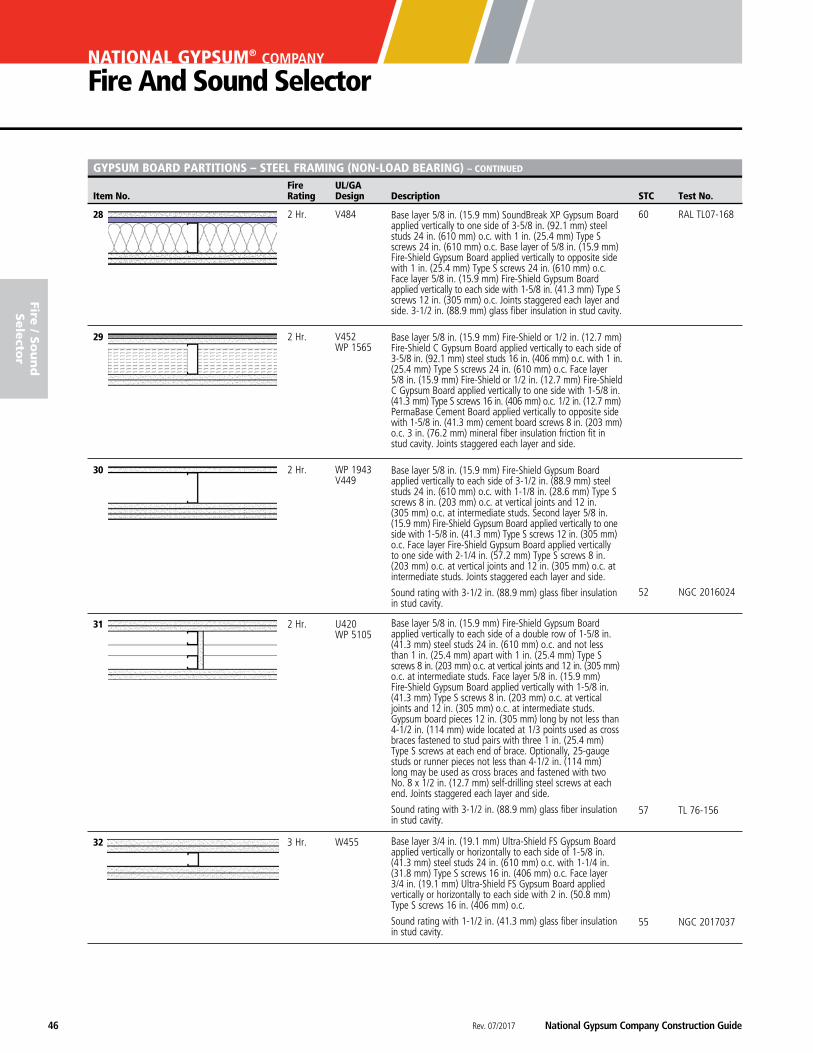
28 2 Hr. V484 60 RAL TL07-168
29 2 Hr. V452 WP 1565
30 2 Hr. WP 1943 V449
52 NGC 2016024
31 2 Hr. U420 WP 5105
57 TL 76-156
32 3 Hr. W455
55 NGC 2017037
Base layer 5/8 in. (15.9 mm) SoundBreak XP Gypsum Board applied vertically to one side of 3-5/8 in. (92.1 mm) steel studs 24 in. (610 mm) o.c. with 1 in. (25.4 mm) Type S screws 24 in. (610 mm) o.c. Base layer of 5/8 in. (15.9 mm) Fire-Shield Gypsum Board applied vertically to opposite side with 1 in. (25.4 mm) Type S screws 24 in. (610 mm) o.c. Face layer 5/8 in. (15.9 mm) Fire-Shield Gypsum Board applied vertically to each side with 1-5/8 in. (41.3 mm) Type S screws 12 in. (305 mm) o.c. Joints staggered each layer and side. 3-1/2 in. (88.9 mm) glass fiber insulation in stud cavity.
Base layer 5/8 in. (15.9 mm) Fire-Shield or 1/2 in. (12.7 mm) Fire-Shield C Gypsum Board applied vertically to each side of 3-5/8 in. (92.1 mm) steel studs 16 in. (406 mm) o.c. with 1 in. (25.4 mm) Type S screws 24 in. (610 mm) o.c. Face layer 5/8 in. (15.9 mm) Fire-Shield or 1/2 in. (12.7 mm) Fire-Shield C Gypsum Board applied vertically to one side with 1-5/8 in. (41.3 mm) Type S screws 16 in. (406 mm) o.c. 1/2 in. (12.7 mm) PermaBase Cement Board applied vertically to opposite side with 1-5/8 in. (41.3 mm) cement board screws 8 in. (203 mm) o.c. 3 in. (76.2 mm) mineral fiber insulation friction fit in stud cavity. Joints staggered each layer and side.
Base layer 5/8 in. (15.9 mm) Fire-Shield Gypsum Board applied vertically to each side of 3-1/2 in. (88.9 mm) steel studs 24 in. (610 mm) o.c. with 1-1/8 in. (28.6 mm) Type S screws 8 in. (203 mm) o.c. at vertical joints and 12 in. (305 mm) o.c. at intermediate studs. Second layer 5/8 in. (15.9 mm) Fire-Shield Gypsum Board applied vertically to one side with 1-5/8 in. (41.3 mm) Type S screws 12 in. (305 mm) o.c. Face layer Fire-Shield Gypsum Board applied vertically to one side with 2-1/4 in. (57.2 mm) Type S screws 8 in. (203 mm) o.c. at vertical joints and 12 in. (305 mm) o.c. at intermediate studs. Joints staggered each layer and side.
Sound rating with 3-1/2 in. (88.9 mm) glass fiber insulation in stud cavity.
Base layer 5/8 in. (15.9 mm) Fire-Shield Gypsum Board applied vertically to each side of a double row of 1-5/8 in. (41.3 mm) steel studs 24 in. (610 mm) o.c. and not less than 1 in. (25.4 mm) apart with 1 in. (25.4 mm) Type S screws 8 in. (203 mm) o.c. at vertical joints and 12 in. (305 mm) o.c. at intermediate studs. Face layer 5/8 in. (15.9 mm) Fire-Shield Gypsum Board applied vertically with 1-5/8 in. (41.3 mm) Type S screws 8 in. (203 mm) o.c. at vertical joints and 12 in. (305 mm) o.c. at intermediate studs. Gypsum board pieces 12 in. (305 mm) long by not less than 4-1/2 in. (114 mm) wide located at 1/3 points used as cross braces fastened to stud pairs with three 1 in. (25.4 mm) Type S screws at each end of brace. Optionally, 25-gauge studs or runner pieces not less than 4-1/2 in. (114 mm) long may be used as cross braces and fastened with two No. 8 x 1/2 in. (12.7 mm) self-drilling steel screws at each end. Joints staggered each layer and side.
Sound rating with 3-1/2 in. (88.9 mm) glass fiber insulation in stud cavity.
Base layer 3/4 in. (19.1 mm) Ultra-Shield FS Gypsum Board applied vertically or horizontally to each side of 1-5/8 in. (41.3 mm) steel studs 24 in. (610 mm) o.c. with 1-1/4 in. (31.8 mm) Type S screws 16 in. (406 mm) o.c. Face layer 3/4 in. (19.1 mm) Ultra-Shield FS Gypsum Board applied vertically or horizontally to each side with 2 in. (50.8 mm) Type S screws 16 in. (406 mm) o.c.
Sound rating with 1-1/2 in. (41.3 mm) glass fiber insulation in stud cavity.
National Gypsum Company Construction Guide Rev. 07/2017 47
fire
/ S
ou
nd
Sele
cto
r
Fire UL/GA Item No. Rating Design Description STC Test No.
GYPSUM BOARD PARTITIONS – STEEL FRAMING (NON-LOAD BEARING) – CONTINUED
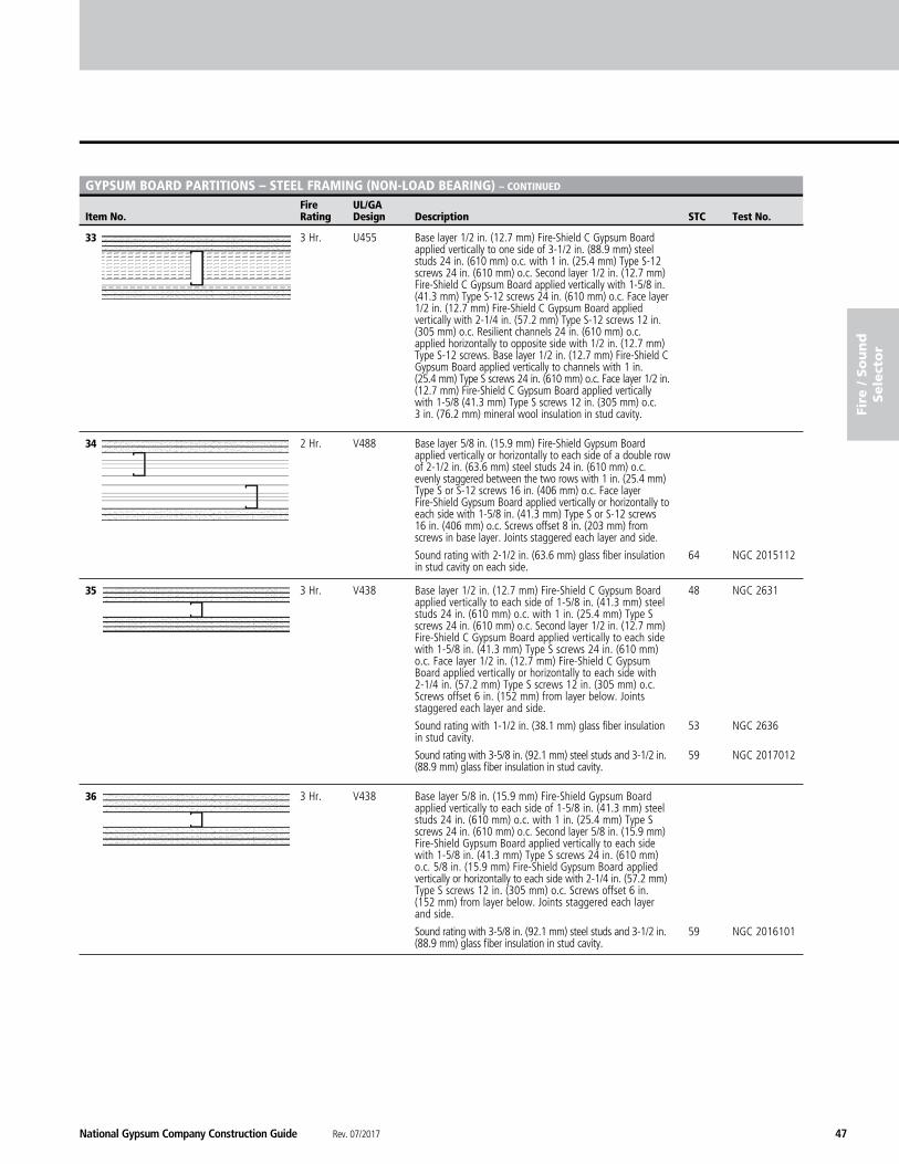
33 3 Hr. U455
34 2 Hr. V488
64 NGC 2015112
35 3 Hr. V438 48 NGC 2631 53 NGC 2636 59 NGC 2017012
36 3 Hr. V438 59 NGC 2016101
Base layer 1/2 in. (12.7 mm) Fire-Shield C Gypsum Board applied vertically to each side of 1-5/8 in. (41.3 mm) steel studs 24 in. (610 mm) o.c. with 1 in. (25.4 mm) Type S screws 24 in. (610 mm) o.c. Second layer 1/2 in. (12.7 mm) Fire-Shield C Gypsum Board applied vertically to each side with 1-5/8 in. (41.3 mm) Type S screws 24 in. (610 mm) o.c. Face layer 1/2 in. (12.7 mm) Fire-Shield C Gypsum Board applied vertically or horizontally to each side with 2-1/4 in. (57.2 mm) Type S screws 12 in. (305 mm) o.c. Screws offset 6 in. (152 mm) from layer below. Joints staggered each layer and side.
Sound rating with 1-1/2 in. (38.1 mm) glass fiber insulation in stud cavity.
Sound rating with 3-5/8 in. (92.1 mm) steel studs and 3-1/2 in. (88.9 mm) glass fiber insulation in stud cavity.
Base layer 5/8 in. (15.9 mm) Fire-Shield Gypsum Board applied vertically to each side of 1-5/8 in. (41.3 mm) steel studs 24 in. (610 mm) o.c. with 1 in. (25.4 mm) Type S screws 24 in. (610 mm) o.c. Second layer 5/8 in. (15.9 mm) Fire-Shield Gypsum Board applied vertically to each side with 1-5/8 in. (41.3 mm) Type S screws 24 in. (610 mm) o.c. 5/8 in. (15.9 mm) Fire-Shield Gypsum Board applied vertically or horizontally to each side with 2-1/4 in. (57.2 mm) Type S screws 12 in. (305 mm) o.c. Screws offset 6 in. (152 mm) from layer below. Joints staggered each layer and side.
Sound rating with 3-5/8 in. (92.1 mm) steel studs and 3-1/2 in. (88.9 mm) glass fiber insulation in stud cavity.
Base layer 5/8 in. (15.9 mm) Fire-Shield Gypsum Board applied vertically or horizontally to each side of a double row of 2-1/2 in. (63.6 mm) steel studs 24 in. (610 mm) o.c. evenly staggered between the two rows with 1 in. (25.4 mm) Type S or S-12 screws 16 in. (406 mm) o.c. Face layer Fire-Shield Gypsum Board applied vertically or horizontally to each side with 1-5/8 in. (41.3 mm) Type S or S-12 screws 16 in. (406 mm) o.c. Screws offset 8 in. (203 mm) from screws in base layer. Joints staggered each layer and side.
Sound rating with 2-1/2 in. (63.6 mm) glass fiber insulation in stud cavity on each side.
Base layer 1/2 in. (12.7 mm) Fire-Shield C Gypsum Board applied vertically to one side of 3-1/2 in. (88.9 mm) steel studs 24 in. (610 mm) o.c. with 1 in. (25.4 mm) Type S-12 screws 24 in. (610 mm) o.c. Second layer 1/2 in. (12.7 mm) Fire-Shield C Gypsum Board applied vertically with 1-5/8 in. (41.3 mm) Type S-12 screws 24 in. (610 mm) o.c. Face layer 1/2 in. (12.7 mm) Fire-Shield C Gypsum Board applied vertically with 2-1/4 in. (57.2 mm) Type S-12 screws 12 in. (305 mm) o.c. Resilient channels 24 in. (610 mm) o.c. applied horizontally to opposite side with 1/2 in. (12.7 mm) Type S-12 screws. Base layer 1/2 in. (12.7 mm) Fire-Shield C Gypsum Board applied vertically to channels with 1 in. (25.4 mm) Type S screws 24 in. (610 mm) o.c. Face layer 1/2 in. (12.7 mm) Fire-Shield C Gypsum Board applied vertically with 1-5/8 (41.3 mm) Type S screws 12 in. (305 mm) o.c. 3 in. (76.2 mm) mineral wool insulation in stud cavity.
Rev. 07/2017 National Gypsum Company Construction Guide48
NATIONAL GYPSUM® COMPANY
Fire And Sound Selector
fire / S
ou
nd
Sele
ctor
Fire UL/GA Item No. Rating Design Description STC Test No.
GYPSUM BOARD PARTITIONS – STEEL FRAMING (NON-LOAD BEARING) – CONTINUED
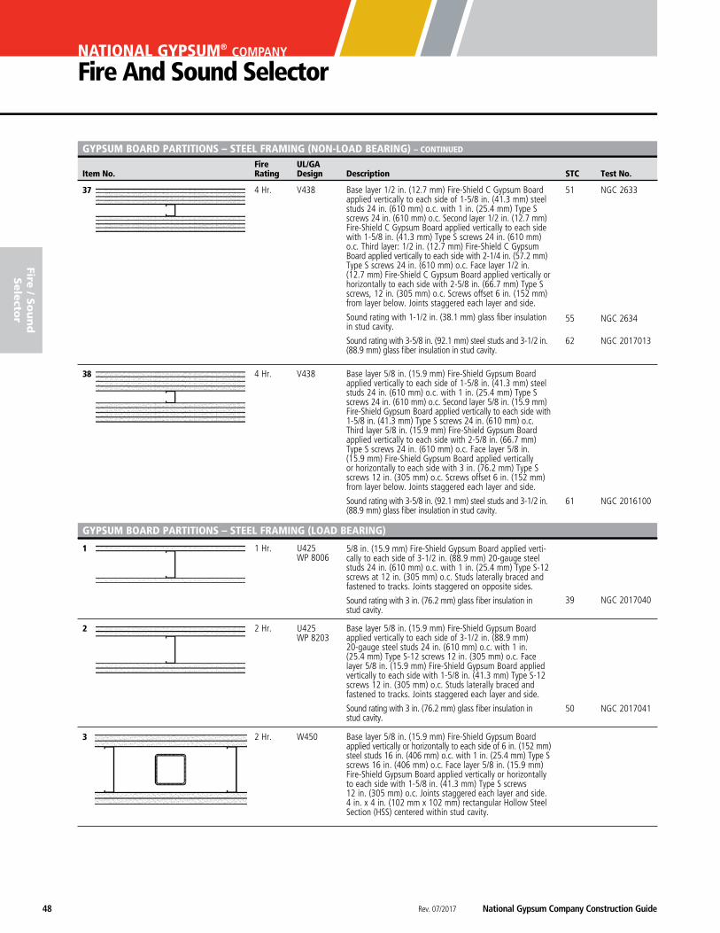
37 4 Hr. V438 51 NGC 2633
55 NGC 2634 62 NGC 2017013
38 4 Hr. V438
61 NGC 2016100
1 1 Hr. U425 WP 8006
39 NGC 2017040
2 2 Hr. U425 WP 8203
50 NGC 2017041
3 2 Hr. W450
5/8 in. (15.9 mm) Fire-Shield Gypsum Board applied verti-cally to each side of 3-1/2 in. (88.9 mm) 20-gauge steel studs 24 in. (610 mm) o.c. with 1 in. (25.4 mm) Type S-12 screws at 12 in. (305 mm) o.c. Studs laterally braced and fastened to tracks. Joints staggered on opposite sides.
Sound rating with 3 in. (76.2 mm) glass fiber insulation in stud cavity.
Base layer 5/8 in. (15.9 mm) Fire-Shield Gypsum Board applied vertically to each side of 3-1/2 in. (88.9 mm) 20-gauge steel studs 24 in. (610 mm) o.c. with 1 in. (25.4 mm) Type S-12 screws 12 in. (305 mm) o.c. Face layer 5/8 in. (15.9 mm) Fire-Shield Gypsum Board applied vertically to each side with 1-5/8 in. (41.3 mm) Type S-12 screws 12 in. (305 mm) o.c. Studs laterally braced and fastened to tracks. Joints staggered each layer and side.
Sound rating with 3 in. (76.2 mm) glass fiber insulation in stud cavity.
Base layer 5/8 in. (15.9 mm) Fire-Shield Gypsum Board applied vertically or horizontally to each side of 6 in. (152 mm) steel studs 16 in. (406 mm) o.c. with 1 in. (25.4 mm) Type S screws 16 in. (406 mm) o.c. Face layer 5/8 in. (15.9 mm) Fire-Shield Gypsum Board applied vertically or horizontally to each side with 1-5/8 in. (41.3 mm) Type S screws 12 in. (305 mm) o.c. Joints staggered each layer and side. 4 in. x 4 in. (102 mm x 102 mm) rectangular Hollow Steel Section (HSS) centered within stud cavity.
Base layer 5/8 in. (15.9 mm) Fire-Shield Gypsum Board applied vertically to each side of 1-5/8 in. (41.3 mm) steel studs 24 in. (610 mm) o.c. with 1 in. (25.4 mm) Type S screws 24 in. (610 mm) o.c. Second layer 5/8 in. (15.9 mm) Fire-Shield Gypsum Board applied vertically to each side with 1-5/8 in. (41.3 mm) Type S screws 24 in. (610 mm) o.c. Third layer 5/8 in. (15.9 mm) Fire-Shield Gypsum Board applied vertically to each side with 2-5/8 in. (66.7 mm) Type S screws 24 in. (610 mm) o.c. Face layer 5/8 in. (15.9 mm) Fire-Shield Gypsum Board applied vertically or horizontally to each side with 3 in. (76.2 mm) Type S screws 12 in. (305 mm) o.c. Screws offset 6 in. (152 mm) from layer below. Joints staggered each layer and side.
Sound rating with 3-5/8 in. (92.1 mm) steel studs and 3-1/2 in. (88.9 mm) glass fiber insulation in stud cavity.
Base layer 1/2 in. (12.7 mm) Fire-Shield C Gypsum Board applied vertically to each side of 1-5/8 in. (41.3 mm) steel studs 24 in. (610 mm) o.c. with 1 in. (25.4 mm) Type S screws 24 in. (610 mm) o.c. Second layer 1/2 in. (12.7 mm) Fire-Shield C Gypsum Board applied vertically to each side with 1-5/8 in. (41.3 mm) Type S screws 24 in. (610 mm) o.c. Third layer: 1/2 in. (12.7 mm) Fire-Shield C Gypsum Board applied vertically to each side with 2-1/4 in. (57.2 mm) Type S screws 24 in. (610 mm) o.c. Face layer 1/2 in. (12.7 mm) Fire-Shield C Gypsum Board applied vertically or horizontally to each side with 2-5/8 in. (66.7 mm) Type S screws, 12 in. (305 mm) o.c. Screws offset 6 in. (152 mm) from layer below. Joints staggered each layer and side.
Sound rating with 1-1/2 in. (38.1 mm) glass fiber insulation in stud cavity.
Sound rating with 3-5/8 in. (92.1 mm) steel studs and 3-1/2 in. (88.9 mm) glass fiber insulation in stud cavity.
GYPSUM BOARD PARTITIONS – STEEL FRAMING (LOAD BEARING)
National Gypsum Company Construction Guide Rev. 07/2017 49
fire
/ S
ou
nd
Sele
cto
r
Fire UL/GA Item No. Rating Design Description STC Test No.
GYPSUM BOARD PARTITIONS – STEEL FRAMING (LOAD BEARING) – CONTINUED
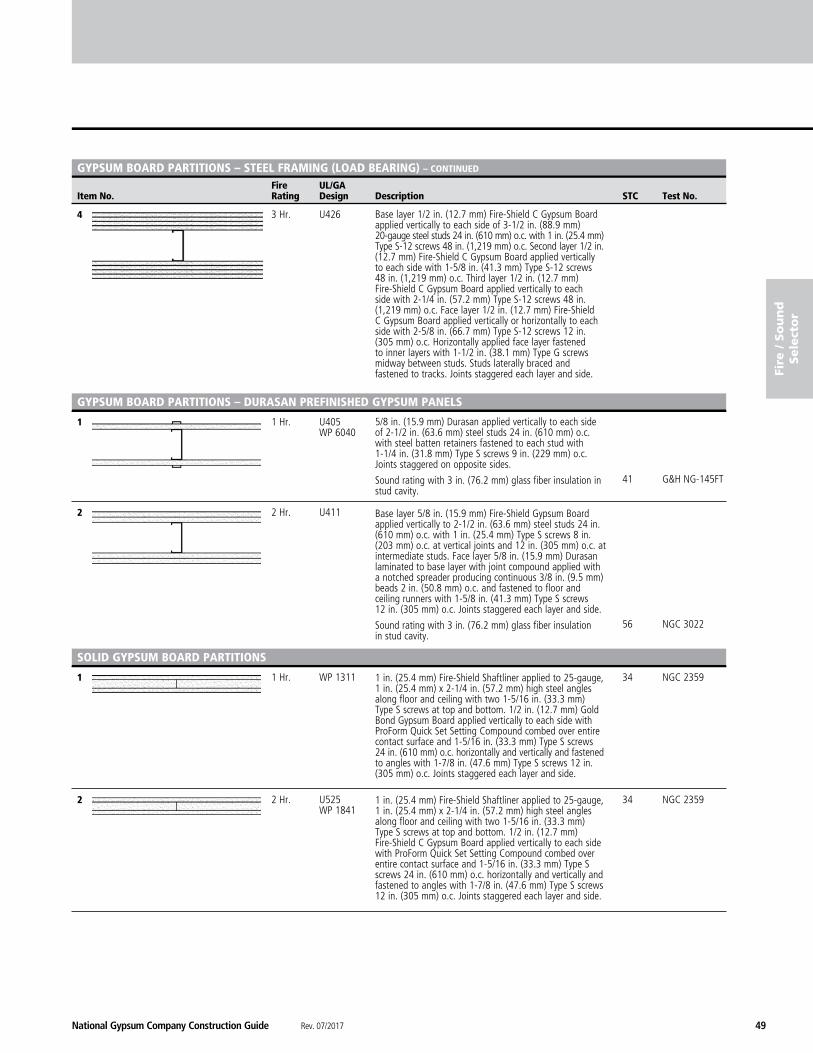
4 3 Hr. U426
1 1 Hr. U405 WP 6040 41 G&H NG-145FT
2 2 Hr. U411 56 NGC 3022
1 1 Hr. WP 1311 34 NGC 2359
2 2 Hr. U525 34 NGC 2359 WP 1841
1 in. (25.4 mm) Fire-Shield Shaftliner applied to 25-gauge, 1 in. (25.4 mm) x 2-1/4 in. (57.2 mm) high steel angles along floor and ceiling with two 1-5/16 in. (33.3 mm) Type S screws at top and bottom. 1/2 in. (12.7 mm) Gold Bond Gypsum Board applied vertically to each side with ProForm Quick Set Setting Compound combed over entire contact surface and 1-5/16 in. (33.3 mm) Type S screws 24 in. (610 mm) o.c. horizontally and vertically and fastened to angles with 1-7/8 in. (47.6 mm) Type S screws 12 in. (305 mm) o.c. Joints staggered each layer and side.
1 in. (25.4 mm) Fire-Shield Shaftliner applied to 25-gauge, 1 in. (25.4 mm) x 2-1/4 in. (57.2 mm) high steel angles along floor and ceiling with two 1-5/16 in. (33.3 mm) Type S screws at top and bottom. 1/2 in. (12.7 mm) Fire-Shield C Gypsum Board applied vertically to each side with ProForm Quick Set Setting Compound combed over entire contact surface and 1-5/16 in. (33.3 mm) Type S screws 24 in. (610 mm) o.c. horizontally and vertically and fastened to angles with 1-7/8 in. (47.6 mm) Type S screws 12 in. (305 mm) o.c. Joints staggered each layer and side.
Base layer 1/2 in. (12.7 mm) Fire-Shield C Gypsum Board applied vertically to each side of 3-1/2 in. (88.9 mm) 20-gauge steel studs 24 in. (610 mm) o.c. with 1 in. (25.4 mm) Type S-12 screws 48 in. (1,219 mm) o.c. Second layer 1/2 in. (12.7 mm) Fire-Shield C Gypsum Board applied vertically to each side with 1-5/8 in. (41.3 mm) Type S-12 screws 48 in. (1,219 mm) o.c. Third layer 1/2 in. (12.7 mm) Fire-Shield C Gypsum Board applied vertically to each side with 2-1/4 in. (57.2 mm) Type S-12 screws 48 in. (1,219 mm) o.c. Face layer 1/2 in. (12.7 mm) Fire-Shield C Gypsum Board applied vertically or horizontally to each side with 2-5/8 in. (66.7 mm) Type S-12 screws 12 in. (305 mm) o.c. Horizontally applied face layer fastened to inner layers with 1-1/2 in. (38.1 mm) Type G screws midway between studs. Studs laterally braced and fastened to tracks. Joints staggered each layer and side.
5/8 in. (15.9 mm) Durasan applied vertically to each side of 2-1/2 in. (63.6 mm) steel studs 24 in. (610 mm) o.c. with steel batten retainers fastened to each stud with 1-1/4 in. (31.8 mm) Type S screws 9 in. (229 mm) o.c. Joints staggered on opposite sides.
Sound rating with 3 in. (76.2 mm) glass fiber insulation in stud cavity.
Base layer 5/8 in. (15.9 mm) Fire-Shield Gypsum Board applied vertically to 2-1/2 in. (63.6 mm) steel studs 24 in. (610 mm) o.c. with 1 in. (25.4 mm) Type S screws 8 in. (203 mm) o.c. at vertical joints and 12 in. (305 mm) o.c. at intermediate studs. Face layer 5/8 in. (15.9 mm) Durasan laminated to base layer with joint compound applied with a notched spreader producing continuous 3/8 in. (9.5 mm) beads 2 in. (50.8 mm) o.c. and fastened to floor and ceiling runners with 1-5/8 in. (41.3 mm) Type S screws 12 in. (305 mm) o.c. Joints staggered each layer and side.
Sound rating with 3 in. (76.2 mm) glass fiber insulation in stud cavity.
GYPSUM BOARD PARTITIONS – DURASAN PREFINIShED GYPSUM PANELS
SOLID GYPSUM BOARD PARTITIONS

Rev. 07/2017 National Gypsum Company Construction Guide50
NATIONAL GYPSUM® COMPANY
Fire And Sound Selector
Fire UL/GA Item No. Rating Design Description STC Test No.
fire / S
ou
nd
Sele
ctor
SOLID GYPSUM BOARD PARTITIONS – CONTINUED
3 2 Hr. U505 WP 7210
4 2 Hr. U529
1 1 Hr. W419 37 NGC 2001003 U499 WP 6905
42 NGC 2016033
2 1 Hr. W419 44 NGC 2015035 U499
3 1 Hr. W419 48 NGC 2541 U499
22-gauge, 3/4 in. (19.1 mm) x 1-1/4 in. (31.8 mm) high steel angle along floor and 22-gauge, 3/4 in. (19.1 mm) x 1-1/4 in. (31.8 mm) x 30 in. (762 mm) long steel angles fastened to end walls and spaced maximum 5 ft. (1,524 mm) o.c. 25-gauge, 1 in. (25.4 mm) x 1-5/8 in. (41.3 mm) steel channel fastened to ceiling with one leg aligned with wall angles and oriented so the first two layers of gypsum board can be inserted into the channel. 25-gauge, 3/4 in. (19.1 mm) x 1-1/4 in. (31.8 mm) horizontal bracing angles spaced 5 ft. (1,524 mm) o.c. with 1-1/4 in. (31.8 mm) leg fastened to 1-1/4 in. (31.8 mm) leg of wall angles. Base layer 5/8 in. (15.9 mm) Fire-Shield Gypsum Board applied vertically with top edge inserted into ceiling channel to floor, wall, and bracing angles with 1 in. (25.4 mm) Type S screws 16 in. (406 mm) o.c. Second layer 1 in. (25.4 mm) Fire-Shield Shaftliner applied vertically with top edge inserted into ceiling channel with ProForm Quick Set Setting Compound combed over entire contact surface and to floor, wall and bracing angles with 2-1/4 in. (57.2 mm) Type S-12 screws 12 in. (305 mm) o.c. Additional angles fastened to floor and end walls with 1-1/4 in. (31.8 mm) leg flat against the shaftliner panel. Face layer 5/8 in. (15.9 mm) Fire-Shield Gypsum Board applied vertically with ProForm Quick Set Setting Compound combed over entire contact surface and to ceiling channel and floor and wall angles with 1 in. (25.4 mm) Type S screws 16 in. (406 mm) o.c. Joints staggered each layer and side.
25-gauge 1 in. (25.4 mm) x 2 in. (50.8 mm) steel angles fastened to floor, ceiling and end walls. Base layer 1/2 in. (12.7 mm) Fire-Shield C Gypsum Board applied vertically to angles with 1 in. (25.4 mm) Type S screws 12 in. (305 mm) o.c. Second layer 1 in. (25.4 mm) Fire-Shield Shaftliner applied vertically with ProForm Quick Set Setting Compound combed over entire contact surface and 1-1/2 in. (38.1 mm) Type G screws 24 in. (610 mm) o.c. vertically and horizontally. Face layer 1/2 in. (12.7 mm) Fire-Shield C Gypsum Board applied vertically with ProForm Quick Set Setting Compound combed over entire contact surface and 1-1/2 in. (38.1 mm) Type G screws 24 in. (610 mm) o.c. vertically and horizontally. Joints staggered each layer and side.
GYPSUM BOARD PARTITIONS – ShAFTWALL SYSTEMS
1 in. (25.4 mm) Fire-Shield Shaftliner inserted between flanges of 2-1/2 in. (63.6 mm) steel C-T, C-H or I studs 24 in. (610 mm) o.c. 5/8 in. (15.9 mm) Fire-Shield Gypsum Board applied vertically or horizontally to studs with 1 in. (25.4 mm) Type S screws 12 in. (305 mm) o.c. on side opposite shaftliner panel.
Sound rating with 1-1/2 in. (38.1 mm) glass fiber insulation in stud cavity.
1 in. (25.4 mm) Fire-Shield Shaftliner inserted between flanges of 2-1/2 in. (63.6 mm) steel C-T, C-H or I studs 24 in. (610 mm) o.c. 5/8 in. (15.9 mm) SoundBreak XP Gypsum Board applied vertically to studs with 1 in. (25.4 mm) Type S screws 12 in. (305 mm) o.c. on side opposite shaftliner panel. 1-1/2 in. (38.1 mm) glass fiber insulation in stud cavity.
1 in. (25.4 mm) Fire-Shield Shaftliner inserted between flanges of 2-1/2 in. (63.6 mm) steel C-T, C-H or I studs 24 in. (610 mm) o.c. Resilient channels applied horizontally to studs 24 in. (610 mm) o.c. with 1/2 in. (12.7 mm) pan-head screws on side opposite shaftliner panel. 5/8 in. (19.1 mm) Fire-Shield Gypsum Board applied vertically to channels with 1 in. (25.4 mm) Type S screws 12 in. (305 mm) o.c. 1-1/2 in. (38.1 mm) glass fiber insulation in stud cavity.
National Gypsum Company Construction Guide Rev. 07/2017 51
fire
/ S
ou
nd
Sele
cto
r
Fire UL/GA Item No. Rating Design Description STC Test No.
GYPSUM BOARD PARTITIONS – ShAFTWALL SYSTEMS – CONTINUED
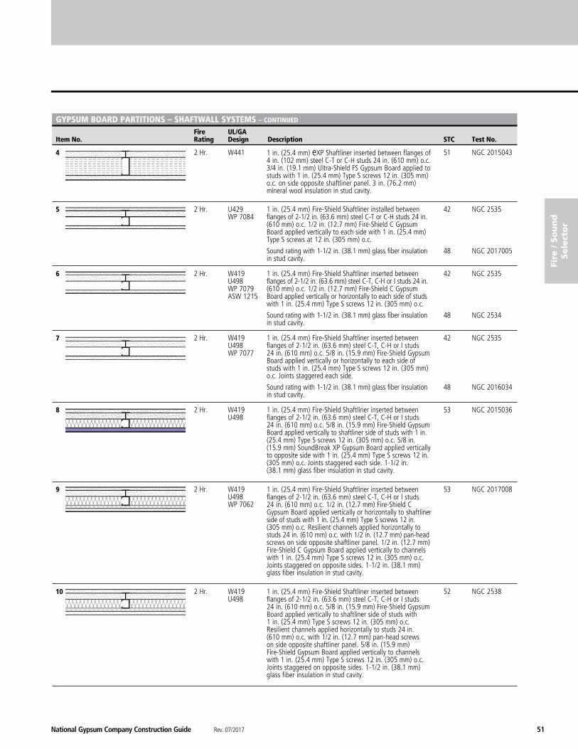
4 2 Hr. W441 51 NGC 2015043
5 2 Hr. U429 42 NGC 2535 WP 7084
48 NGC 2017005
6 2 Hr. W419 42 NGC 2535 U498 WP 7079 ASW 1215
48 NGC 2534
7 2 Hr. W419 42 NGC 2535 U498 WP 7077
48 NGC 2016034
8 2 Hr. W419 53 NGC 2015036 U498
9 2 Hr. W419 53 NGC 2017008 U498 WP 7062
10 2 Hr. W419 52 NGC 2538 U498
1 in. (25.4 mm) eXP Shaftliner inserted between flanges of 4 in. (102 mm) steel C-T or C-H studs 24 in. (610 mm) o.c. 3/4 in. (19.1 mm) Ultra-Shield FS Gypsum Board applied to studs with 1 in. (25.4 mm) Type S screws 12 in. (305 mm) o.c. on side opposite shaftliner panel. 3 in. (76.2 mm) mineral wool insulation in stud cavity.
1 in. (25.4 mm) Fire-Shield Shaftliner installed between flanges of 2-1/2 in. (63.6 mm) steel C-T or C-H studs 24 in. (610 mm) o.c. 1/2 in. (12.7 mm) Fire-Shield C Gypsum Board applied vertically to each side with 1 in. (25.4 mm) Type S screws at 12 in. (305 mm) o.c.
Sound rating with 1-1/2 in. (38.1 mm) glass fiber insulation in stud cavity.
1 in. (25.4 mm) Fire-Shield Shaftliner inserted between flanges of 2-1/2 in. (63.6 mm) steel C-T, C-H or I studs 24 in. (610 mm) o.c. 1/2 in. (12.7 mm) Fire-Shield C Gypsum Board applied vertically or horizontally to each side of studs with 1 in. (25.4 mm) Type S screws 12 in. (305 mm) o.c.
Sound rating with 1-1/2 in. (38.1 mm) glass fiber insulation in stud cavity.
1 in. (25.4 mm) Fire-Shield Shaftliner inserted between flanges of 2-1/2 in. (63.6 mm) steel C-T, C-H or I studs 24 in. (610 mm) o.c. 5/8 in. (15.9 mm) Fire-Shield Gypsum Board applied vertically or horizontally to each side of studs with 1 in. (25.4 mm) Type S screws 12 in. (305 mm) o.c. Joints staggered each side.
Sound rating with 1-1/2 in. (38.1 mm) glass fiber insulation in stud cavity.
1 in. (25.4 mm) Fire-Shield Shaftliner inserted between flanges of 2-1/2 in. (63.6 mm) steel C-T, C-H or I studs 24 in. (610 mm) o.c. 5/8 in. (15.9 mm) Fire-Shield Gypsum Board applied vertically to shaftliner side of studs with 1 in. (25.4 mm) Type S screws 12 in. (305 mm) o.c. 5/8 in. (15.9 mm) SoundBreak XP Gypsum Board applied vertically to opposite side with 1 in. (25.4 mm) Type S screws 12 in. (305 mm) o.c. Joints staggered each side. 1-1/2 in. (38.1 mm) glass fiber insulation in stud cavity.
1 in. (25.4 mm) Fire-Shield Shaftliner inserted between flanges of 2-1/2 in. (63.6 mm) steel C-T, C-H or I studs 24 in. (610 mm) o.c. 1/2 in. (12.7 mm) Fire-Shield C Gypsum Board applied vertically or horizontally to shaftliner side of studs with 1 in. (25.4 mm) Type S screws 12 in. (305 mm) o.c. Resilient channels applied horizontally to studs 24 in. (610 mm) o.c. with 1/2 in. (12.7 mm) pan-head screws on side opposite shaftliner panel. 1/2 in. (12.7 mm) Fire-Shield C Gypsum Board applied vertically to channels with 1 in. (25.4 mm) Type S screws 12 in. (305 mm) o.c. Joints staggered on opposite sides. 1-1/2 in. (38.1 mm) glass fiber insulation in stud cavity.
1 in. (25.4 mm) Fire-Shield Shaftliner inserted between flanges of 2-1/2 in. (63.6 mm) steel C-T, C-H or I studs 24 in. (610 mm) o.c. 5/8 in. (15.9 mm) Fire-Shield Gypsum Board applied vertically to shaftliner side of studs with 1 in. (25.4 mm) Type S screws 12 in. (305 mm) o.c. Resilient channels applied horizontally to studs 24 in. (610 mm) o.c. with 1/2 in. (12.7 mm) pan-head screws on side opposite shaftliner panel. 5/8 in. (15.9 mm) Fire-Shield Gypsum Board applied vertically to channels with 1 in. (25.4 mm) Type S screws 12 in. (305 mm) o.c. Joints staggered on opposite sides. 1-1/2 in. (38.1 mm) glass fiber insulation in stud cavity.
Rev. 07/2017 National Gypsum Company Construction Guide52
NATIONAL GYPSUM® COMPANY
Fire And Sound Selector
Fire UL/GA Item No. Rating Design Description STC Test No.
fire / S
ou
nd
Sele
ctor
GYPSUM BOARD PARTITIONS – ShAFTWALL SYSTEMS – CONTINUED
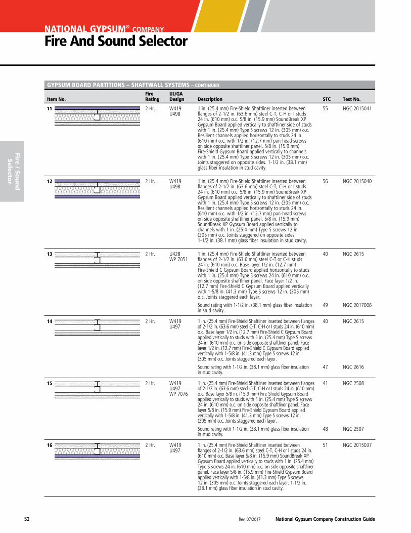
11 2 Hr. W419 55 NGC 2015041 U498
12 2 Hr. W419 56 NGC 2015040 U498
13 2 Hr. U428 40 NGC 2615 WP 7051
49 NGC 2017006
14 2 Hr. W419 40 NGC 2615 U497
47 NGC 2616
15 2 Hr. W419 41 NGC 2508 U497 WP 7076
48 NGC 2507
16 2 Hr. W419 51 NGC 2015037 U497
1 in. (25.4 mm) Fire-Shield Shaftliner inserted between flanges of 2-1/2 in. (63.6 mm) steel C-T, C-H or I studs 24 in. (610 mm) o.c. Base layer 1/2 in. (12.7 mm) Fire-Shield C Gypsum Board applied vertically to studs with 1 in. (25.4 mm) Type S screws 24 in. (610 mm) o.c. on side opposite shaftliner panel. Face layer 1/2 in. (12.7 mm) Fire-Shield C Gypsum Board applied vertically with 1-5/8 in. (41.3 mm) Type S screws 12 in. (305 mm) o.c. Joints staggered each layer.
Sound rating with 1-1/2 in. (38.1 mm) glass fiber insulation in stud cavity.
1 in. (25.4 mm) Fire-Shield Shaftliner inserted between flanges of 2-1/2 in. (63.6 mm) steel C-T, C-H or I studs 24 in. (610 mm) o.c. Base layer 5/8 in. (15.9 mm) Fire-Shield Gypsum Board applied vertically to studs with 1 in. (25.4 mm) Type S screws 24 in. (610 mm) o.c. on side opposite shaftliner panel. Face layer 5/8 in. (15.9 mm) Fire-Shield Gypsum Board applied vertically with 1-5/8 in. (41.3 mm) Type S screws 12 in. (305 mm) o.c. Joints staggered each layer.
Sound rating with 1-1/2 in. (38.1 mm) glass fiber insulation in stud cavity.
1 in. (25.4 mm) Fire-Shield Shaftliner inserted between flanges of 2-1/2 in. (63.6 mm) steel C-T, C-H or I studs 24 in. (610 mm) o.c. Base layer 5/8 in. (15.9 mm) SoundBreak XP Gypsum Board applied vertically to studs with 1 in. (25.4 mm) Type S screws 24 in. (610 mm) o.c. on side opposite shaftliner panel. Face layer 5/8 in. (15.9 mm) Fire-Shield Gypsum Board applied vertically with 1-5/8 in. (41.3 mm) Type S screws 12 in. (305 mm) o.c. Joints staggered each layer. 1-1/2 in. (38.1 mm) glass fiber insulation in stud cavity.
1 in. (25.4 mm) Fire-Shield Shaftliner inserted between flanges of 2-1/2 in. (63.6 mm) steel C-T, C-H or I studs 24 in. (610 mm) o.c. 5/8 in. (15.9 mm) SoundBreak XP Gypsum Board applied vertically to shaftliner side of studs with 1 in. (25.4 mm) Type S screws 12 in. (305 mm) o.c. Resilient channels applied horizontally to studs 24 in. (610 mm) o.c. with 1/2 in. (12.7 mm) pan-head screws on side opposite shaftliner panel. 5/8 in. (15.9 mm) Fire-Shield Gypsum Board applied vertically to channels with 1 in. (25.4 mm) Type S screws 12 in. (305 mm) o.c. Joints staggered on opposite sides. 1-1/2 in. (38.1 mm) glass fiber insulation in stud cavity.
1 in. (25.4 mm) Fire-Shield Shaftliner inserted between flanges of 2-1/2 in. (63.6 mm) steel C-T, C-H or I studs 24 in. (610 mm) o.c. 5/8 in. (15.9 mm) SoundBreak XP Gypsum Board applied vertically to shaftliner side of studs with 1 in. (25.4 mm) Type S screws 12 in. (305 mm) o.c. Resilient channels applied horizontally to studs 24 in. (610 mm) o.c. with 1/2 in. (12.7 mm) pan-head screws on side opposite shaftliner panel. 5/8 in. (15.9 mm) SoundBreak XP Gypsum Board applied vertically to channels with 1 in. (25.4 mm) Type S screws 12 in. (305 mm) o.c. Joints staggered on opposite sides. 1-1/2 in. (38.1 mm) glass fiber insulation in stud cavity.
1 in. (25.4 mm) Fire-Shield Shaftliner inserted between flanges of 2-1/2 in. (63.6 mm) steel C-T or C-H studs 24 in. (610 mm) o.c. Base layer 1/2 in. (12.7 mm) Fire-Shield C Gypsum Board applied horizontally to studs with 1 in. (25.4 mm) Type S screws 24 in. (610 mm) o.c. on side opposite shaftliner panel. Face layer 1/2 in. (12.7 mm) Fire-Shield C Gypsum Board applied vertically with 1-5/8 in. (41.3 mm) Type S screws 12 in. (305 mm) o.c. Joints staggered each layer.
Sound rating with 1-1/2 in. (38.1 mm) glass fiber insulation in stud cavity.
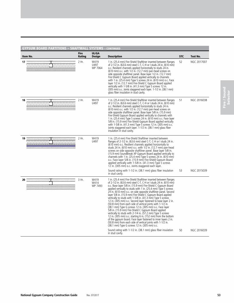
National Gypsum Company Construction Guide Rev. 07/2017 53
fire
/ S
ou
nd
Sele
cto
r
Fire UL/GA Item No. Rating Design Description STC Test No.
GYPSUM BOARD PARTITIONS – ShAFTWALL SYSTEMS – CONTINUED
17 2 Hr. W419 52 NGC 2017007 U497 WP 7064
18 2 Hr. W419 51 NGC 2016038 U497
19 2 Hr. W419 U497
53 NGC 2015039
20 3 Hr. W419 W414 WP 7493 50 NGC 2016039
1 in. (25.4 mm) Fire-Shield Shaftliner inserted between flanges of 2-1/2 in. (63.6 mm) steel C-T, C-H or I studs 24 in. (610 mm) o.c. Resilient channels applied horizontally to studs 24 in. (610 mm) o.c. with 1/2 in. (12.7 mm) pan-head screws on side opposite shaftliner panel. Base layer 1/2 in. (12.7 mm) Fire-Shield C Gypsum Board applied vertically to channels with 1 in. (25.4 mm) Type S screws 24 in. (610 mm) o.c. Face layer 1/2 in. (12.7 mm) Fire-Shield C Gypsum Board applied vertically with 1-5/8 in. (41.3 mm) Type S screws 12 in. (305 mm) o.c. Joints staggered each layer. 1-1/2 in. (38.1 mm) glass fiber insulation in stud cavity.
1 in. (25.4 mm) Fire-Shield Shaftliner inserted between flanges of 2-1/2 in. (63.6 mm) steel C-T, C-H or I studs 24 in. (610 mm) o.c. Resilient channels applied horizontally to studs 24 in. (610 mm) o.c. with 1/2 in. (12.7 mm) pan-head screws on side opposite shaftliner panel. Base layer 5/8 in. (15.9 mm) Fire-Shield Gypsum Board applied vertically to channels with 1 in. (25.4 mm) Type S screws 24 in. (610 mm) o.c. Face layer 5/8 in. (15.9 mm) Fire-Shield Gypsum Board applied vertically with 1-5/8 in. (41.3 mm) Type S screws 12 in. (305 mm) o.c. Joints staggered each layer. 1-1/2 in. (38.1 mm) glass fiber insulation in stud cavity.
1 in. (25.4 mm) Fire-Shield Shaftliner inserted between flanges of 2-1/2 in. (63.6 mm) steel C-T, C-H or I studs 24 in. (610 mm) o.c. Resilient channels applied horizontally to studs 24 in. (610 mm) o.c. with 1/2 in. (12.7 mm) pan-head screws on side opposite shaftliner panel. Base layer 5/8 in. (15.9 mm) SoundBreak XP Gypsum Board applied vertically to channels with 1 in. (25.4 mm) Type S screws 24 in. (610 mm) o.c. Face layer 5/8 in. (15.9 mm) Fire-Shield Gypsum Board applied vertically with 1-5/8 in. (41.3 mm) Type S screws 12 in. (305 mm) o.c. Joints staggered each layer.
Sound rating with 1-1/2 in. (38.1 mm) glass fiber insulation in stud cavity.
1 in. (25.4 mm) Fire-Shield Shaftliner inserted between flanges of 2-1/2 in. (63.6 mm) steel C-T, C-H or I studs 24 in. (610 mm) o.c. Base layer 5/8 in. (15.9 mm) Fire-Shield C Gypsum Board applied vertically to studs with 1 in. (25.4 mm) Type S screws 24 in. (610 mm) o.c. on side opposite shaftliner panel. Second layer 5/8 in. (15.9 mm) Fire-Shield C Gypsum Board applied vertically to studs with 1-5/8 in. (41.3 mm) Type S screws 12 in. (305 mm) o.c. Second layer fastened to base layer 2 in. (50.8 mm) from each side of vertical joints with 1-1/2 in. (38.1 mm) Type G screws 12 in. (305 mm) o.c. Face layer 5/8 in. (15.9 mm) Fire-Shield C Gypsum Board applied vertically to studs with 2-1/4 in. (57.2 mm) Type S screws 12 in. (305 mm) o.c. starting 6 in. (152 mm) from the bottom of the gypsum board. Face layer fastened to inner layers 2 in. (50.8 mm) from each side of vertical joints with 1-1/2 in. (38.1 mm) Type G screws 12 in. (305 mm) o.c.
Sound rating with 1-1/2 in. (38.1 mm) glass fiber insulation in stud cavity.
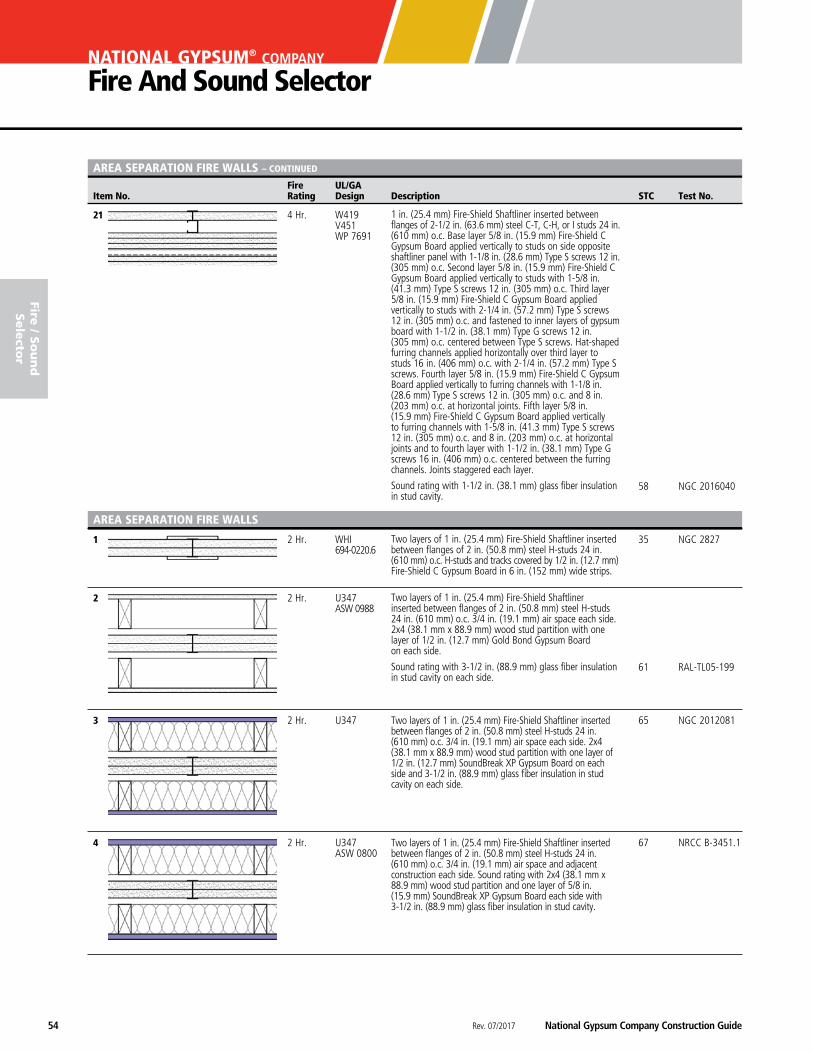
Rev. 07/2017 National Gypsum Company Construction Guide54
NATIONAL GYPSUM® COMPANY
Fire And Sound Selector
Fire UL/GA Item No. Rating Design Description STC Test No.
fire / S
ou
nd
Sele
ctor
AREA SEPARATION FIRE WALLS – CONTINUED
21 4 Hr. W419 V451 WP 7691 58 NGC 2016040
1 2 Hr. WHI 35 NGC 2827 694-0220.6
2 2 Hr. U347 ASW 0988
61 RAL-TL05-199
3 2 Hr. U347 65 NGC 2012081
4 2 Hr. U347 67 NRCC B-3451.1 ASW 0800
Two layers of 1 in. (25.4 mm) Fire-Shield Shaftliner inserted between flanges of 2 in. (50.8 mm) steel H-studs 24 in. (610 mm) o.c. 3/4 in. (19.1 mm) air space each side. 2x4 (38.1 mm x 88.9 mm) wood stud partition with one layer of 1/2 in. (12.7 mm) SoundBreak XP Gypsum Board on each side and 3-1/2 in. (88.9 mm) glass fiber insulation in stud cavity on each side.
Two layers of 1 in. (25.4 mm) Fire-Shield Shaftliner inserted between flanges of 2 in. (50.8 mm) steel H-studs 24 in. (610 mm) o.c. 3/4 in. (19.1 mm) air space and adjacent construction each side. Sound rating with 2x4 (38.1 mm x 88.9 mm) wood stud partition and one layer of 5/8 in. (15.9 mm) SoundBreak XP Gypsum Board each side with 3-1/2 in. (88.9 mm) glass fiber insulation in stud cavity.
1 in. (25.4 mm) Fire-Shield Shaftliner inserted between flanges of 2-1/2 in. (63.6 mm) steel C-T, C-H, or I studs 24 in. (610 mm) o.c. Base layer 5/8 in. (15.9 mm) Fire-Shield C Gypsum Board applied vertically to studs on side opposite shaftliner panel with 1-1/8 in. (28.6 mm) Type S screws 12 in. (305 mm) o.c. Second layer 5/8 in. (15.9 mm) Fire-Shield C Gypsum Board applied vertically to studs with 1-5/8 in. (41.3 mm) Type S screws 12 in. (305 mm) o.c. Third layer 5/8 in. (15.9 mm) Fire-Shield C Gypsum Board applied vertically to studs with 2-1/4 in. (57.2 mm) Type S screws 12 in. (305 mm) o.c. and fastened to inner layers of gypsum board with 1-1/2 in. (38.1 mm) Type G screws 12 in. (305 mm) o.c. centered between Type S screws. Hat-shaped furring channels applied horizontally over third layer to studs 16 in. (406 mm) o.c. with 2-1/4 in. (57.2 mm) Type S screws. Fourth layer 5/8 in. (15.9 mm) Fire-Shield C Gypsum Board applied vertically to furring channels with 1-1/8 in. (28.6 mm) Type S screws 12 in. (305 mm) o.c. and 8 in. (203 mm) o.c. at horizontal joints. Fifth layer 5/8 in. (15.9 mm) Fire-Shield C Gypsum Board applied vertically to furring channels with 1-5/8 in. (41.3 mm) Type S screws 12 in. (305 mm) o.c. and 8 in. (203 mm) o.c. at horizontal joints and to fourth layer with 1-1/2 in. (38.1 mm) Type G screws 16 in. (406 mm) o.c. centered between the furring channels. Joints staggered each layer.
Sound rating with 1-1/2 in. (38.1 mm) glass fiber insulation in stud cavity.
Two layers of 1 in. (25.4 mm) Fire-Shield Shaftliner inserted between flanges of 2 in. (50.8 mm) steel H-studs 24 in. (610 mm) o.c. H-studs and tracks covered by 1/2 in. (12.7 mm) Fire-Shield C Gypsum Board in 6 in. (152 mm) wide strips.
Two layers of 1 in. (25.4 mm) Fire-Shield Shaftliner inserted between flanges of 2 in. (50.8 mm) steel H-studs 24 in. (610 mm) o.c. 3/4 in. (19.1 mm) air space each side. 2x4 (38.1 mm x 88.9 mm) wood stud partition with one layer of 1/2 in. (12.7 mm) Gold Bond Gypsum Board on each side.
Sound rating with 3-1/2 in. (88.9 mm) glass fiber insulation in stud cavity on each side.
AREA SEPARATION FIRE WALLS
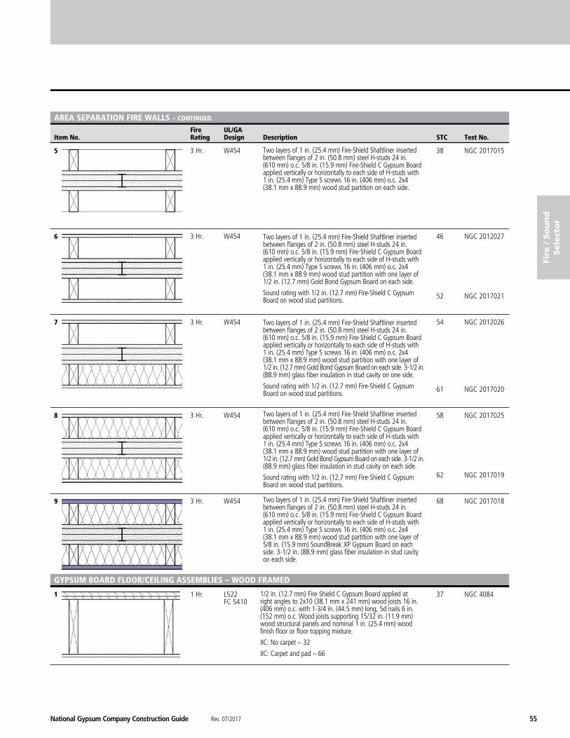
National Gypsum Company Construction Guide Rev. 07/2017 55
fire
/ S
ou
nd
Sele
cto
r
Fire UL/GA Item No. Rating Design Description STC Test No.
AREA SEPARATION FIRE WALLS – CONTINUED
5 3 Hr. W454 38 NGC 2017015
6 3 Hr. W454 46 NGC 2012027 52 NGC 2017021
7 3 Hr. W454 54 NGC 2012026 61 NGC 2017020
8 3 Hr. W454 58 NGC 2017025 62 NGC 2017019
9 3 Hr. W454 68 NGC 2017018
1 1 Hr. L522 37 NGC 4084 FC 5410
GYPSUM BOARD FLOOR/CEILING ASSEMBLIES – WOOD FRAMED
1/2 in. (12.7 mm) Fire-Shield C Gypsum Board applied at right angles to 2x10 (38.1 mm x 241 mm) wood joists 16 in. (406 mm) o.c. with 1-3/4 in. (44.5 mm) long, 5d nails 6 in. (152 mm) o.c. Wood joists supporting 15/32 in. (11.9 mm) wood structural panels and nominal 1 in. (25.4 mm) wood finish floor or floor topping mixture.
IIC: No carpet – 32
IIC: Carpet and pad – 66
Two layers of 1 in. (25.4 mm) Fire-Shield Shaftliner inserted between flanges of 2 in. (50.8 mm) steel H-studs 24 in. (610 mm) o.c. 5/8 in. (15.9 mm) Fire-Shield C Gypsum Board applied vertically or horizontally to each side of H-studs with 1 in. (25.4 mm) Type S screws 16 in. (406 mm) o.c. 2x4 (38.1 mm x 88.9 mm) wood stud partition on each side.
Two layers of 1 in. (25.4 mm) Fire-Shield Shaftliner inserted between flanges of 2 in. (50.8 mm) steel H-studs 24 in. (610 mm) o.c. 5/8 in. (15.9 mm) Fire-Shield C Gypsum Board applied vertically or horizontally to each side of H-studs with 1 in. (25.4 mm) Type S screws 16 in. (406 mm) o.c. 2x4 (38.1 mm x 88.9 mm) wood stud partition with one layer of 1/2 in. (12.7 mm) Gold Bond Gypsum Board on each side.
Sound rating with 1/2 in. (12.7 mm) Fire-Shield C Gypsum Board on wood stud partitions.
Two layers of 1 in. (25.4 mm) Fire-Shield Shaftliner inserted between flanges of 2 in. (50.8 mm) steel H-studs 24 in. (610 mm) o.c. 5/8 in. (15.9 mm) Fire-Shield C Gypsum Board applied vertically or horizontally to each side of H-studs with 1 in. (25.4 mm) Type S screws 16 in. (406 mm) o.c. 2x4 (38.1 mm x 88.9 mm) wood stud partition with one layer of 1/2 in. (12.7 mm) Gold Bond Gypsum Board on each side. 3-1/2 in. (88.9 mm) glass fiber insulation in stud cavity on one side.
Sound rating with 1/2 in. (12.7 mm) Fire-Shield C Gypsum Board on wood stud partitions.
Two layers of 1 in. (25.4 mm) Fire-Shield Shaftliner inserted between flanges of 2 in. (50.8 mm) steel H-studs 24 in. (610 mm) o.c. 5/8 in. (15.9 mm) Fire-Shield C Gypsum Board applied vertically or horizontally to each side of H-studs with 1 in. (25.4 mm) Type S screws 16 in. (406 mm) o.c. 2x4 (38.1 mm x 88.9 mm) wood stud partition with one layer of 1/2 in. (12.7 mm) Gold Bond Gypsum Board on each side. 3-1/2 in. (88.9 mm) glass fiber insulation in stud cavity on each side.
Sound rating with 1/2 in. (12.7 mm) Fire-Shield C Gypsum Board on wood stud partitions.
Two layers of 1 in. (25.4 mm) Fire-Shield Shaftliner inserted between flanges of 2 in. (50.8 mm) steel H-studs 24 in. (610 mm) o.c. 5/8 in. (15.9 mm) Fire-Shield C Gypsum Board applied vertically or horizontally to each side of H-studs with 1 in. (25.4 mm) Type S screws 16 in. (406 mm) o.c. 2x4 (38.1 mm x 88.9 mm) wood stud partition with one layer of 5/8 in. (15.9 mm) SoundBreak XP Gypsum Board on each side. 3-1/2 in. (88.9 mm) glass fiber insulation in stud cavity on each side.
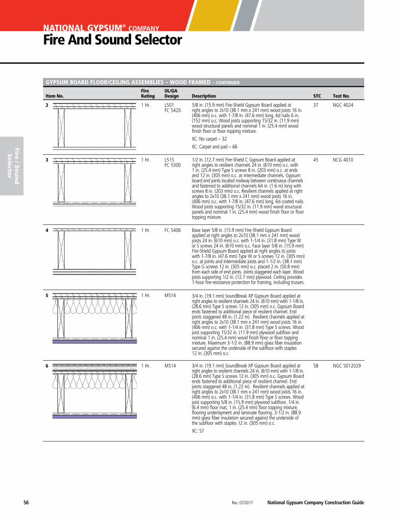
Rev. 07/2017 National Gypsum Company Construction Guide56
NATIONAL GYPSUM® COMPANY
Fire And Sound Selector
Fire UL/GA Item No. Rating Design Description STC Test No.
fire / S
ou
nd
Sele
ctor
GYPSUM BOARD FLOOR/CEILING ASSEMBLIES – WOOD FRAMED – CONTINUED
2 1 Hr. L501 37 NGC 4024 FC 5420
3 1 Hr. L515 45 NCG 4010 FC 5300
4 1 Hr. FC 5406
5 1 Hr. M514
6 1 Hr. M514 58 NGC 5012029
5/8 in. (15.9 mm) Fire-Shield Gypsum Board applied at right angles to 2x10 (38.1 mm x 241 mm) wood joists 16 in. (406 mm) o.c. with 1-7/8 in. (47.6 mm) long, 6d nails 6 in. (152 mm) o.c. Wood joists supporting 15/32 in. (11.9 mm) wood structural panels and nominal 1 in. (25.4 mm) wood finish floor or floor topping mixture.
IIC: No carpet – 32
IIC: Carpet and pad – 66
1/2 in. (12.7 mm) Fire-Shield C Gypsum Board applied at right angles to resilient channels 24 in. (610 mm) o.c. with 1 in. (25.4 mm) Type S screws 8 in. (203 mm) o.c. at ends and 12 in. (305 mm) o.c. at intermediate channels. Gypsum board end joints located midway between continuous channels and fastened to additional channels 64 in. (1.6 m) long with screws 8 in. (203 mm) o.c. Resilient channels applied at right angles to 2x10 (38.1 mm x 241 mm) wood joists 16 in. (406 mm) o.c. with 1-7/8 in. (47.6 mm) long, 6d coated nails. Wood joists supporting 15/32 in. (11.9 mm) wood structural panels and nominal 1 in. (25.4 mm) wood finish floor or floor topping mixture.
3/4 in. (19.1 mm) SoundBreak XP Gypsum Board applied at right angles to resilient channels 24 in. (610 mm) with 1-1/8 in. (28.6 mm) Type S screws 12 in. (305 mm) o.c. Gypsum Board ends fastened to additional piece of resilient channel. End joints staggered 48 in. (1.22 m). Resilient channels applied at right angles to 2x10 (38.1 mm x 241 mm) wood joists 16 in. (406 mm) o.c. with 1-1/4 in. (31.8 mm) Type S screws. Wood joist supporting 15/32 in. (11.9 mm) plywood subfloor and nominal 1 in. (25.4 mm) wood finish floor or floor topping mixture. Maximum 3-1/2 in. (88.9 mm) glass fiber insulation secured against the underside of the subfloor with staples 12 in. (305 mm) o.c.
3/4 in. (19.1 mm) SoundBreak XP Gypsum Board applied at right angles to resilient channels 24 in. (610 mm) with 1-1/8 in. (28.6 mm) Type S screws 12 in. (305 mm) o.c. Gypsum Board ends fastened to additional piece of resilient channel. End joints staggered 48 in. (1.22 m). Resilient channels applied at right angles to 2x10 (38.1 mm x 241 mm) wood joists 16 in. (406 mm) o.c. with 1-1/4 in. (31.8 mm) Type S screws. Wood joist supporting 5/8 in. (15.9 mm) plywood subfloor, 1/4 in. (6.4 mm) floor mat, 1 in. (25.4 mm) floor topping mixture, flooring underlayment and laminate flooring. 3-1/2 in. (88.9 mm) glass fiber insulation secured against the underside of the subfloor with staples 12 in. (305 mm) o.c.
IIC: 57
Base layer 5/8 in. (15.9 mm) Fire-Shield Gypsum Board applied at right angles to 2x10 (38.1 mm x 241 mm) wood joists 24 in. (610 mm) o.c. with 1-1/4 in. (31.8 mm) Type W or S screws 24 in. (610 mm) o.c. Face layer 5/8 in. (15.9 mm) Fire-Shield Gypsum Board applied at right angles to joists with 1-7/8 in. (47.6 mm) Type W or S screws 12 in. (305 mm) o.c. at joints and intermediate joists and 1-1/2 in. (38.1 mm) Type G screws 12 in. (305 mm) o.c. placed 2 in. (50.8 mm) from each side of end joints. Joints staggered each layer. Wood joists supporting 1/2 in. (12.7 mm) plywood. Ceiling provides 1-hour fire-resistance protection for framing, including trusses.
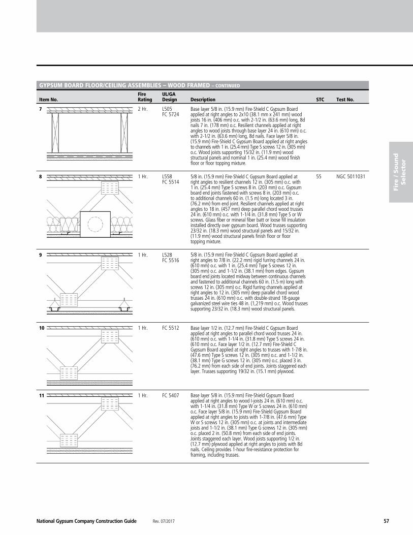
National Gypsum Company Construction Guide Rev. 07/2017 57
fire
/ S
ou
nd
Sele
cto
r
Fire UL/GA Item No. Rating Design Description STC Test No.
GYPSUM BOARD FLOOR/CEILING ASSEMBLIES – WOOD FRAMED – CONTINUED
7 2 Hr. L505 FC 5724
8 1 Hr. L558 55 NGC 5011031 FC 5514
9 1 Hr. L528 FC 5516
10 1 Hr. FC 5512
11 1 Hr. FC 5407
Base layer 5/8 in. (15.9 mm) Fire-Shield Gypsum Board applied at right angles to wood I-joists 24 in. (610 mm) o.c. with 1-1/4 in. (31.8 mm) Type W or S screws 24 in. (610 mm) o.c. Face layer 5/8 in. (15.9 mm) Fire-Shield Gypsum Board applied at right angles to joists with 1-7/8 in. (47.6 mm) Type W or S screws 12 in. (305 mm) o.c. at joints and intermediate joists and 1-1/2 in. (38.1 mm) Type G screws 12 in. (305 mm) o.c. placed 2 in. (50.8 mm) from each side of end joints. Joints staggered each layer. Wood joists supporting 1/2 in. (12.7 mm) plywood applied at right angles to joists with 8d nails. Ceiling provides 1-hour fire-resistance protection for framing, including trusses.
Base layer 5/8 in. (15.9 mm) Fire-Shield C Gypsum Board applied at right angles to 2x10 (38.1 mm x 241 mm) wood joists 16 in. (406 mm) o.c. with 2-1/2 in. (63.6 mm) long, 8d nails 7 in. (178 mm) o.c. Resilient channels applied at right angles to wood joists through base layer 24 in. (610 mm) o.c. with 2-1/2 in. (63.6 mm) long, 8d nails. Face layer 5/8 in. (15.9 mm) Fire-Shield C Gypsum Board applied at right angles to channels with 1 in. (25.4 mm) Type S screws 12 in. (305 mm) o.c. Wood joists supporting 15/32 in. (11.9 mm) wood structural panels and nominal 1 in. (25.4 mm) wood finish floor or floor topping mixture.
5/8 in. (15.9 mm) Fire-Shield C Gypsum Board applied at right angles to resilient channels 12 in. (305 mm) o.c. with 1 in. (25.4 mm) Type S screws 8 in. (203 mm) o.c. Gypsum board end joints fastened with screws 8 in. (203 mm) o.c. to additional channels 60 in. (1.5 m) long located 3 in. (76.2 mm) from end joint. Resilient channels applied at right angles to 18 in. (457 mm) deep parallel chord wood trusses 24 in. (610 mm) o.c. with 1-1/4 in. (31.8 mm) Type S or W screws. Glass fiber or mineral fiber batt or loose fill insulation installed directly over gypsum board. Wood trusses supporting 23/32 in. (18.3 mm) wood structural panels and 15/32 in. (11.9 mm) wood structural panels finish floor or floor topping mixture.
Base layer 1/2 in. (12.7 mm) Fire-Shield C Gypsum Board applied at right angles to parallel chord wood trusses 24 in. (610 mm) o.c. with 1-1/4 in. (31.8 mm) Type S screws 24 in. (610 mm) o.c. Face layer 1/2 in. (12.7 mm) Fire-Shield C Gypsum Board applied at right angles to trusses with 1-7/8 in. (47.6 mm) Type S screws 12 in. (305 mm) o.c. and 1-1/2 in. (38.1 mm) Type G screws 12 in. (305 mm) o.c. placed 3 in. (76.2 mm) from each side of end joints. Joints staggered each layer. Trusses supporting 19/32 in. (15.1 mm) plywood.
5/8 in. (15.9 mm) Fire-Shield C Gypsum Board applied at right angles to 7/8 in. (22.2 mm) rigid furring channels 24 in. (610 mm) o.c. with 1 in. (25.4 mm) Type S screws 12 in. (305 mm) o.c. and 1-1/2 in. (38.1 mm) from edges. Gypsum board end joints located midway between continuous channels and fastened to additional channels 60 in. (1.5 m) long with screws 12 in. (305 mm) o.c. Rigid furring channels applied at right angles to 12 in. (305 mm) deep parallel chord wood trusses 24 in. (610 mm) o.c. with double-strand 18-gauge galvanized steel wire ties 48 in. (1,219 mm) o.c. Wood trusses supporting 23/32 in. (18.3 mm) wood structural panels.

Rev. 07/2017 National Gypsum Company Construction Guide58
NATIONAL GYPSUM® COMPANY
Fire And Sound Selector
Fire UL/GA Item No. Rating Design Description STC Test No.
fire / S
ou
nd
Sele
ctor
GYPSUM BOARD FLOOR/CEILING ASSEMBLIES – WOOD FRAMED – CONTINUED
12 2 Hr. M500
13 2 Hr. L556 FC 5751
14 2 Hr. L538
15 2 Hr. L556 FC 5750
Base layer 5/8 in. (15.9 mm) Fire-Shield C Gypsum Board applied at right angles to 12 in. (305 mm) deep parallel chord wood trusses with 1-5/8 in. (41.3 mm) Type S screws 8 in. (203 mm) o.c. Resilient furring channels 12 in. (305 mm) o.c. applied at right angles to wood trusses through base layer with 1-7/8 in. (47.6 mm) Type S screws. Second layer 5/8 in. (15.9 mm) Fire-Shield C Gypsum Board applied at right angles to resilient channels with 1 in. (25.4 mm) Type S-12 screws 8 in. (203 mm) o.c. Face layer 5/8 in. (15.9 mm) Fire-Shield C Gypsum Board applied at right angles to resilient channels through second layer with 1-5/8 in. (41.3 mm) Type S-12 screws 8 in. (203 mm) o.c. Joints staggered each layer. Mineral wool or glass fiber insulation draped over gypsum board. Trusses supporting 23/32 in. (18.3 mm) wood structural panels and floor topping mixture.
Base layer 5/8 in. (15.9 mm) Fire-Shield Gypsum Board applied at right angles to 18 in. (457 mm) deep parallel chord wood trusses 24 in. (610 mm) o.c. with 1-1/4 in. (31.8 mm) Type W screws 12 in. (305 mm) o.c. Second layer 5/8 in. (15.9 mm) Fire-Shield Gypsum Board applied at right angles to trusses with 2 in. (50.8 mm) Type W screws 12 in. (305 mm) o.c. Joints staggered 24 in. (610 mm) from base layer. Third layer 5/8 in. (15.9 mm) Fire-Shield Gypsum Board applied at right angles to trusses with 2-1/2 in. (63.6 mm) Type W screws 12 in. (305 mm) o.c. Joints staggered 12 in. (50.8 mm) from second layer. 7/8 in. (22.2 mm) rigid furring channels 24 in. (610 mm) o.c. applied at right angles to trusses over third layer with two 2-1/2 in. (63.6 mm) Type W screws at each truss. Face layer 5/8 in. (15.9 mm) Fire-Shield Gypsum Board applied at right angles to furring channels with 1-1/8 in. (28.6 mm) Type S screws 12 in. (305 mm) o.c. Trusses supporting 3/4 in. (19.1 mm) plywood.
Base layer 5/8 in. (15.9 mm) Fire-Shield C Gypsum Board applied at right angles to 9-1/2 in. (241 mm) wood I-joists 19.2 in. (488 mm) o.c. with 1-5/8 in. (41.3 mm) Type S screws 8 in. (203 mm) o.c. Resilient channels 16 in. (406 mm) o.c. applied at right angles to wood joists through base layer with 1-7/8 in. (47.6 mm) Type S screws at each joist. Second layer 5/8 in. (15.9 mm) Fire-Shield C Gypsum Board applied at right angles to resilient channels with 1 in. (25.4 mm) Type S-12 screws 8 in. (203 mm) o.c. Face layer 5/8 in. (15.9 mm) Fire-Shield C Gypsum Board applied at right angles to resilient channels through second layer with 1-5/8 in. (41.3 mm) Type S-12 screws 8 in. (203 mm) o.c. Joints staggered minimum 16 in. (406 mm) from second layer. I-joists supporting 5/8 in. (15.9 mm) wood structural panel floor applied at right angle to joists.
Base layer 5/8 in. (15.9 mm) Fire-Shield Gypsum Board applied at right angles to 9-1/2 in. (241 mm) wood I-joists 24 in. (610 mm) o.c. with 1-1/4 in. (31.8 mm) Type W screws 12 in. (305 mm) o.c. Second layer 5/8 in. (15.9 mm) Fire-Shield Gypsum Board applied at right angles to I-joists with 2 in. (50.8 mm) Type W screws 12 in. (305 mm) o.c. Joints staggered 24 in. (610 mm) from base layer. Third layer 5/8 in. (15.9 mm) Fire-Shield Gypsum Board applied at right angles to I-joists with 2-1/2 in. (63.6 mm) Type W screws 12 in. (305 mm) o.c. Joints staggered 12 in. (305 mm) from second layer. 7/8 in. (22.2 mm) rigid furring channels 24 in. (610 mm) o.c. applied at right angles to I-joists over third layer with two 2-1/2 in. (63.6 mm) Type W screws at each truss. Face layer 5/8 in. (15.9 mm) Fire-Shield Gypsum Board applied at right angles to furring channels with 1-1/8 in. (28.6 mm) Type S screws 12 in. (305 mm) o.c. I-joists supporting 3/4 in. (19.1 mm) plywood.
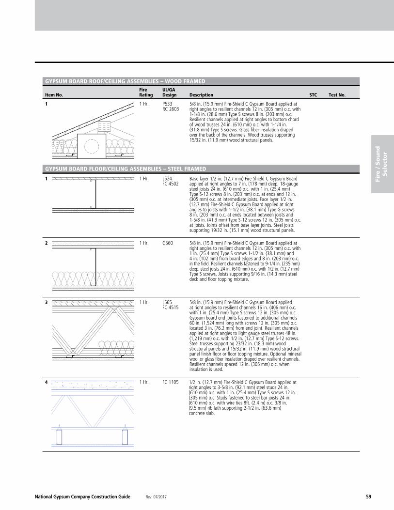
National Gypsum Company Construction Guide Rev. 07/2017 59
fire
/ S
ou
nd
Sele
cto
r
Fire UL/GA Item No. Rating Design Description STC Test No.
GYPSUM BOARD ROOF/CEILING ASSEMBLIES – WOOD FRAMED
1 1 Hr. P533 RC 2603
1 1 Hr. L524 FC 4502
2 1 Hr. G560
3 1 Hr. L565 FC 4515
4 1 Hr. FC 1105
GYPSUM BOARD FLOOR/CEILING ASSEMBLIES – STEEL FRAMED
1/2 in. (12.7 mm) Fire-Shield C Gypsum Board applied at right angles to 3-5/8 in. (92.1 mm) steel studs 24 in. (610 mm) o.c. with 1 in. (25.4 mm) Type S screws 12 in. (305 mm) o.c. Studs fastened to steel bar joists 24 in. (610 mm) o.c. with wire ties 8ft. (2.4 m) o.c. 3/8 in. (9.5 mm) rib lath supporting 2-1/2 in. (63.6 mm) concrete slab.
5/8 in. (15.9 mm) Fire-Shield C Gypsum Board applied at right angles to resilient channels 12 in. (305 mm) o.c. with 1-1/8 in. (28.6 mm) Type S screws 8 in. (203 mm) o.c. Resilient channels applied at right angles to bottom chord of wood trusses 24 in. (610 mm) o.c. with 1-1/4 in. (31.8 mm) Type S screws. Glass fiber insulation draped over the back of the channels. Wood trusses supporting 15/32 in. (11.9 mm) wood structural panels.
Base layer 1/2 in. (12.7 mm) Fire-Shield C Gypsum Board applied at right angles to 7 in. (178 mm) deep, 18-gauge steel joists 24 in. (610 mm) o.c. with 1 in. (25.4 mm) Type S-12 screws 8 in. (203 mm) o.c. at ends and 12 in. (305 mm) o.c. at intermediate joists. Face layer 1/2 in. (12.7 mm) Fire-Shield C Gypsum Board applied at right angles to joists with 1-1/2 in. (38.1 mm) Type G screws 8 in. (203 mm) o.c. at ends located between joists and 1-5/8 in. (41.3 mm) Type S-12 screws 12 in. (305 mm) o.c. at joists. Joints offset from base layer joints. Steel joists supporting 19/32 in. (15.1 mm) wood structural panels.
5/8 in. (15.9 mm) Fire-Shield C Gypsum Board applied at right angles to resilient channels 12 in. (305 mm) o.c. with 1 in. (25.4 mm) Type S screws 1-1/2 in. (38.1 mm) and 4 in. (102 mm) from board edges and 8 in. (203 mm) o.c. in the field. Resilient channels fastened to 9-1/4 in. (235 mm) deep, steel joists 24 in. (610 mm) o.c. with 1/2 in. (12.7 mm) Type S screws. Joists supporting 9/16 in. (14.3 mm) steel deck and floor topping mixture.
5/8 in. (15.9 mm) Fire-Shield C Gypsum Board applied at right angles to resilient channels 16 in. (406 mm) o.c. with 1 in. (25.4 mm) Type S screws 12 in. (305 mm) o.c. Gypsum board end joints fastened to additional channels 60 in. (1,524 mm) long with screws 12 in. (305 mm) o.c. located 3 in. (76.2 mm) from end joint. Resilient channels applied at right angles to light gauge steel trusses 48 in. (1,219 mm) o.c. with 1/2 in. (12.7 mm) Type S-12 screws. Steel trusses supporting 23/32 in. (18.3 mm) wood structural panels and 15/32 in. (11.9 mm) wood structural panel finish floor or floor topping mixture. Optional mineral wool or glass fiber insulation draped over resilient channels. Resilient channels spaced 12 in. (305 mm) o.c. when insulation is used.
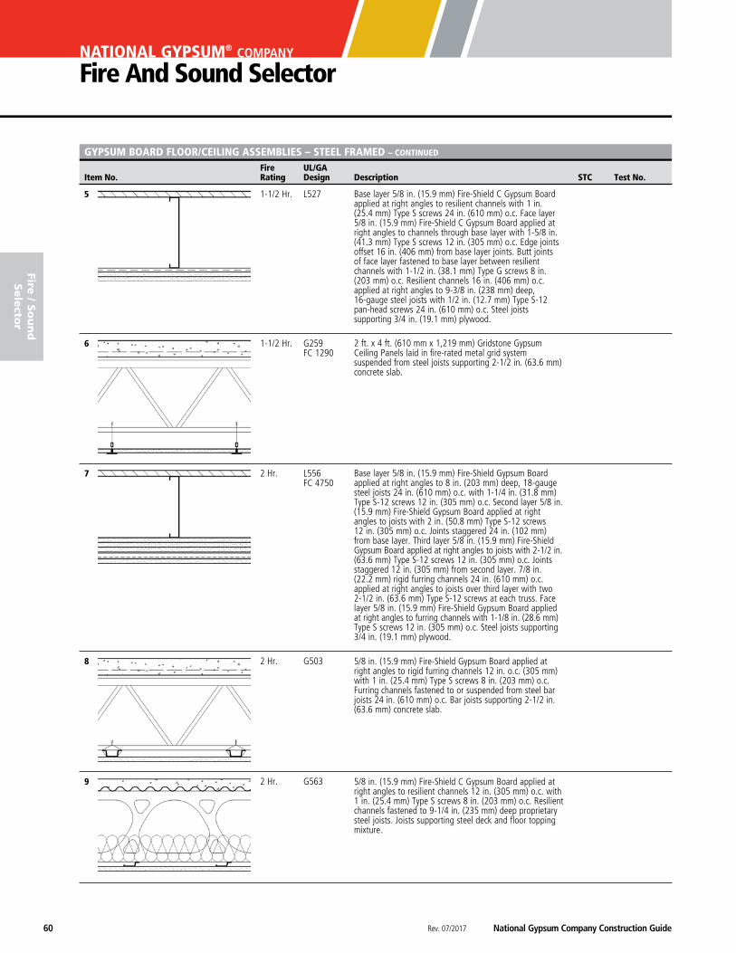
Rev. 07/2017 National Gypsum Company Construction Guide60
NATIONAL GYPSUM® COMPANY
Fire And Sound Selector
Fire UL/GA Item No. Rating Design Description STC Test No.
fire / S
ou
nd
Sele
ctor
GYPSUM BOARD FLOOR/CEILING ASSEMBLIES – STEEL FRAMED – CONTINUED
5 1-1/2 Hr. L527
6 1-1/2 Hr. G259 FC 1290
7 2 Hr. L556 FC 4750
8 2 Hr. G503
9 2 Hr. G563
Base layer 5/8 in. (15.9 mm) Fire-Shield C Gypsum Board applied at right angles to resilient channels with 1 in. (25.4 mm) Type S screws 24 in. (610 mm) o.c. Face layer 5/8 in. (15.9 mm) Fire-Shield C Gypsum Board applied at right angles to channels through base layer with 1-5/8 in. (41.3 mm) Type S screws 12 in. (305 mm) o.c. Edge joints offset 16 in. (406 mm) from base layer joints. Butt joints of face layer fastened to base layer between resilient channels with 1-1/2 in. (38.1 mm) Type G screws 8 in. (203 mm) o.c. Resilient channels 16 in. (406 mm) o.c. applied at right angles to 9-3/8 in. (238 mm) deep, 16-gauge steel joists with 1/2 in. (12.7 mm) Type S-12 pan-head screws 24 in. (610 mm) o.c. Steel joists supporting 3/4 in. (19.1 mm) plywood.
2 ft. x 4 ft. (610 mm x 1,219 mm) Gridstone Gypsum Ceiling Panels laid in fire-rated metal grid system suspended from steel joists supporting 2-1/2 in. (63.6 mm) concrete slab.
Base layer 5/8 in. (15.9 mm) Fire-Shield Gypsum Board applied at right angles to 8 in. (203 mm) deep, 18-gauge steel joists 24 in. (610 mm) o.c. with 1-1/4 in. (31.8 mm) Type S-12 screws 12 in. (305 mm) o.c. Second layer 5/8 in. (15.9 mm) Fire-Shield Gypsum Board applied at right angles to joists with 2 in. (50.8 mm) Type S-12 screws 12 in. (305 mm) o.c. Joints staggered 24 in. (102 mm) from base layer. Third layer 5/8 in. (15.9 mm) Fire-Shield Gypsum Board applied at right angles to joists with 2-1/2 in. (63.6 mm) Type S-12 screws 12 in. (305 mm) o.c. Joints staggered 12 in. (305 mm) from second layer. 7/8 in. (22.2 mm) rigid furring channels 24 in. (610 mm) o.c. applied at right angles to joists over third layer with two 2-1/2 in. (63.6 mm) Type S-12 screws at each truss. Face layer 5/8 in. (15.9 mm) Fire-Shield Gypsum Board applied at right angles to furring channels with 1-1/8 in. (28.6 mm) Type S screws 12 in. (305 mm) o.c. Steel joists supporting 3/4 in. (19.1 mm) plywood.
5/8 in. (15.9 mm) Fire-Shield Gypsum Board applied at right angles to rigid furring channels 12 in. o.c. (305 mm) with 1 in. (25.4 mm) Type S screws 8 in. (203 mm) o.c. Furring channels fastened to or suspended from steel bar joists 24 in. (610 mm) o.c. Bar joists supporting 2-1/2 in. (63.6 mm) concrete slab.
5/8 in. (15.9 mm) Fire-Shield C Gypsum Board applied at right angles to resilient channels 12 in. (305 mm) o.c. with 1 in. (25.4 mm) Type S screws 8 in. (203 mm) o.c. Resilient channels fastened to 9-1/4 in. (235 mm) deep proprietary steel joists. Joists supporting steel deck and floor topping mixture.
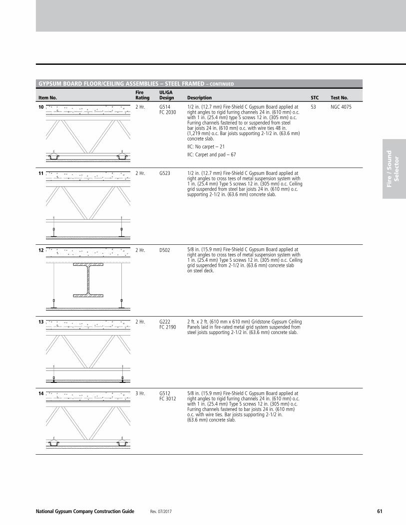
National Gypsum Company Construction Guide Rev. 07/2017 61
fire
/ S
ou
nd
Sele
cto
r
Fire UL/GA Item No. Rating Design Description STC Test No.
GYPSUM BOARD FLOOR/CEILING ASSEMBLIES – STEEL FRAMED – CONTINUED
10 2 Hr. G514 53 NGC 4075 FC 2030
11 2 Hr. G523
12 2 Hr. D502
13 2 Hr. G222 FC 2190
14 3 Hr. G512 FC 3012
2 ft. x 2 ft. (610 mm x 610 mm) Gridstone Gypsum Ceiling Panels laid in fire-rated metal grid system suspended from steel joists supporting 2-1/2 in. (63.6 mm) concrete slab.
5/8 in. (15.9 mm) Fire-Shield C Gypsum Board applied at right angles to rigid furring channels 24 in. (610 mm) o.c. with 1 in. (25.4 mm) Type S screws 12 in. (305 mm) o.c. Furring channels fastened to bar joists 24 in. (610 mm) o.c. with wire ties. Bar joists supporting 2-1/2 in. (63.6 mm) concrete slab.
1/2 in. (12.7 mm) Fire-Shield C Gypsum Board applied at right angles to rigid furring channels 24 in. (610 mm) o.c. with 1 in. (25.4 mm) type S screws 12 in. (305 mm) o.c. Furring channels fastened to or suspended from steel bar joists 24 in. (610 mm) o.c. with wire ties 48 in. (1,219 mm) o.c. Bar joists supporting 2-1/2 in. (63.6 mm) concrete slab.
IIC: No carpet – 21
IIC: Carpet and pad – 67
1/2 in. (12.7 mm) Fire-Shield C Gypsum Board applied at right angles to cross tees of metal suspension system with 1 in. (25.4 mm) Type S screws 12 in. (305 mm) o.c. Ceiling grid suspended from steel bar joists 24 in. (610 mm) o.c. supporting 2-1/2 in. (63.6 mm) concrete slab.
5/8 in. (15.9 mm) Fire-Shield C Gypsum Board applied at right angles to cross tees of metal suspension system with 1 in. (25.4 mm) Type S screws 12 in. (305 mm) o.c. Ceiling grid suspended from 2-1/2 in. (63.6 mm) concrete slab on steel deck.
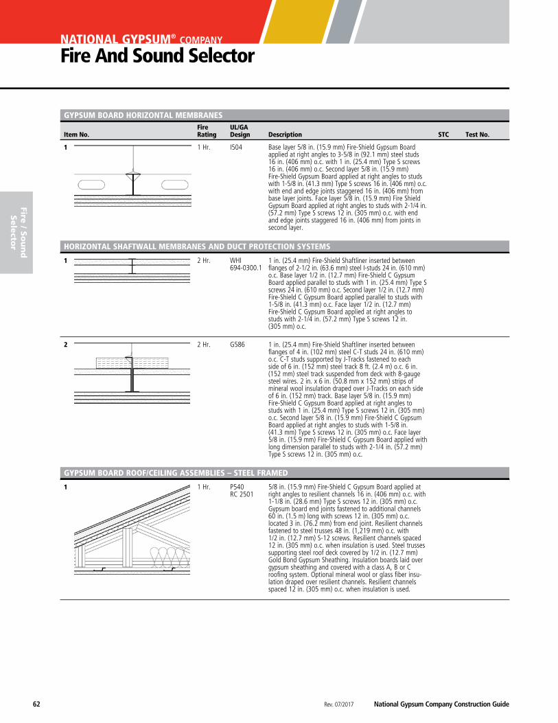
Rev. 07/2017 National Gypsum Company Construction Guide62
NATIONAL GYPSUM® COMPANY
Fire And Sound Selector
Fire UL/GA Item No. Rating Design Description STC Test No.
fire / S
ou
nd
Sele
ctor
GYPSUM BOARD hORIzONTAL MEMBRANES
1 1 Hr. I504
1 2 Hr. WHI 694-0300.1
2 2 Hr. G586
1 1 Hr. P540 RC 2501
Base layer 5/8 in. (15.9 mm) Fire-Shield Gypsum Board applied at right angles to 3-5/8 in (92.1 mm) steel studs 16 in. (406 mm) o.c. with 1 in. (25.4 mm) Type S screws 16 in. (406 mm) o.c. Second layer 5/8 in. (15.9 mm) Fire-Shield Gypsum Board applied at right angles to studs with 1-5/8 in. (41.3 mm) Type S screws 16 in. (406 mm) o.c. with end and edge joints staggered 16 in. (406 mm) from base layer joints. Face layer 5/8 in. (15.9 mm) Fire Shield Gypsum Board applied at right angles to studs with 2-1/4 in. (57.2 mm) Type S screws 12 in. (305 mm) o.c. with end and edge joints staggered 16 in. (406 mm) from joints in second layer.
hORIzONTAL ShAFTWALL MEMBRANES AND DUCT PROTECTION SYSTEMS
1 in. (25.4 mm) Fire-Shield Shaftliner inserted between flanges of 2-1/2 in. (63.6 mm) steel I-studs 24 in. (610 mm) o.c. Base layer 1/2 in. (12.7 mm) Fire-Shield C Gypsum Board applied parallel to studs with 1 in. (25.4 mm) Type S screws 24 in. (610 mm) o.c. Second layer 1/2 in. (12.7 mm) Fire-Shield C Gypsum Board applied parallel to studs with 1-5/8 in. (41.3 mm) o.c. Face layer 1/2 in. (12.7 mm) Fire-Shield C Gypsum Board applied at right angles to studs with 2-1/4 in. (57.2 mm) Type S screws 12 in. (305 mm) o.c.
1 in. (25.4 mm) Fire-Shield Shaftliner inserted between flanges of 4 in. (102 mm) steel C-T studs 24 in. (610 mm) o.c. C-T studs supported by J-Tracks fastened to each side of 6 in. (152 mm) steel track 8 ft. (2.4 m) o.c. 6 in. (152 mm) steel track suspended from deck with 8-gauge steel wires. 2 in. x 6 in. (50.8 mm x 152 mm) strips of mineral wool insulation draped over J-Tracks on each side of 6 in. (152 mm) track. Base layer 5/8 in. (15.9 mm) Fire-Shield C Gypsum Board applied at right angles to studs with 1 in. (25.4 mm) Type S screws 12 in. (305 mm) o.c. Second layer 5/8 in. (15.9 mm) Fire-Shield C Gypsum Board applied at right angles to studs with 1-5/8 in. (41.3 mm) Type S screws 12 in. (305 mm) o.c. Face layer 5/8 in. (15.9 mm) Fire-Shield C Gypsum Board applied with long dimension parallel to studs with 2-1/4 in. (57.2 mm) Type S screws 12 in. (305 mm) o.c.
GYPSUM BOARD ROOF/CEILING ASSEMBLIES – STEEL FRAMED
5/8 in. (15.9 mm) Fire-Shield C Gypsum Board applied at right angles to resilient channels 16 in. (406 mm) o.c. with 1-1/8 in. (28.6 mm) Type S screws 12 in. (305 mm) o.c. Gypsum board end joints fastened to additional channels 60 in. (1.5 m) long with screws 12 in. (305 mm) o.c. located 3 in. (76.2 mm) from end joint. Resilient channels fastened to steel trusses 48 in. (1,219 mm) o.c. with 1/2 in. (12.7 mm) S-12 screws. Resilient channels spaced 12 in. (305 mm) o.c. when insulation is used. Steel trusses supporting steel roof deck covered by 1/2 in. (12.7 mm) Gold Bond Gypsum Sheathing. Insulation boards laid over gypsum sheathing and covered with a class A, B or C roofing system. Optional mineral wool or glass fiber insu-lation draped over resilient channels. Resilient channels spaced 12 in. (305 mm) o.c. when insulation is used.
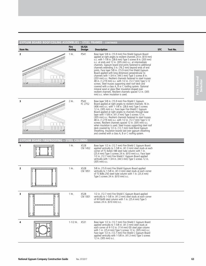
National Gypsum Company Construction Guide Rev. 07/2017 63
fire
/ S
ou
nd
Sele
cto
r
Fire UL/GA Item No. Rating Design Description STC Test No.
GYPSUM BOARD ROOF/CEILING ASSEMBLIES – STEEL FRAMED – CONTINUED
2 1 Hr. P541
3 2 Hr. P543 FC 2752
1 1 Hr. X528 CM 1452
2 1 Hr. X528 CM 1851
3 1 Hr. X528 CM 1001
4 1-1/2 Hr. X531
GYPSUM BOARD FIREPROOFING – STEEL COLUMNS
Base layer 1/2 in. (12.7 mm) Fire-Shield C Gypsum Board applied vertically to 1-5/8 in. (41.3 mm) steel studs at each corner of TS 4x4x0.188 steel tube column with 1 in. (25.4 mm) Type S screws 24 in. (610 mm) o.c. Face layer 1/2 in. (12.7 mm) Fire-Shield C Gypsum Board applied vertically with 1-3/4 in. (44.5 mm) Type S screws 12 in. (305 mm) o.c.
5/8 in. (15.9 mm) Fire-Shield Gypsum Board applied vertically to 1-5/8 in. (41.3 mm) steel studs at each corner of TS 8x8x.250 steel tube column with 1 in. (25.4 mm) Type S screws 24 in. (610 mm) o.c.
1/2 in. (12.7 mm) Fire-Shield C Gypsum Board applied vertically to 1-5/8 in. (41.3 mm) steel studs at each corner of W10x49 steel column with 1 in. (25.4 mm) Type S screws 24 in. (610 mm) o.c.
Base layer 1/2 in. (12.7 mm) Fire-Shield C Gypsum Board applied vertically to 1-5/8 in. (41.3 mm) steel studs at each corner of 4-1/2 in. (114 mm) OD steel pipe column with 1 in. (25.4 mm) Type S screws 12 in. (305 mm) o.c. Face layer 1/2 in. (12.7 mm) Fire-Shield C Gypsum Board applied vertically with 1-5/8 in. (41.3 mm) Type S screws 12 in. (305 mm) o.c.
Base layer 5/8 in. (15.9 mm) Fire-Shield Gypsum Board applied at right angles to resilient channels 24 in. (610 mm) o.c. with 1-1/8 in. (28.6 mm) Type S screws 8 in. (203 mm) o.c. at ends and 12 in. (305 mm) o.c. at intermediate channels. Gypsum board end joints fastened to additional channels extending 3 in. (76.2 mm) beyond ends of end joints. Face layer 5/8 in. (15.9 mm) Fire-Shield Gypsum Board applied with long dimension perpendicular to channels with 1-3/4 in. (44.5 mm) Type S screws 8 in. (203 mm) o.c. Resilient channels fastened to steel trusses 48 in. (1,219 mm) o.c. with 1/2 in. (12.7 mm) Type S-12 screws. Steel trusses supporting steel roof deck and covered with a class A, B or C roofing system. Optional mineral wool or glass fiber insulation draped over resilient channels. Resilient channels spaced 12 in. (305 mm) o.c. when insulation is used.
Base layer 5/8 in. (15.9 mm) Fire-Shield C Gypsum Board applied at right angles to resilient channels 16 in. (406 mm) o.c. with 1-1/8 in. (28.6 mm) Type S screws 12 in. (305 mm) o.c. Face layer Fire-Shield C Gypsum Board applied at right angles to channels through base layer with 1-5/8 in. (41.3 mm) Type S screws 12 in. (305 mm) o.c. Resilient channels fastened to steel trusses 48 in. (1,219 mm) o.c. with 1/2 in. (12.7 mm) Type S-12 screws. Resilient channels spaced 12 in. (305 mm) o.c. when insulation is used. Steel trusses supporting steel roof deck covered by 1/2 in. (12.7 mm) Gold Bond Gypsum Sheathing. Insulation boards laid over gypsum sheathing and covered with a class A, B or C roofing system.
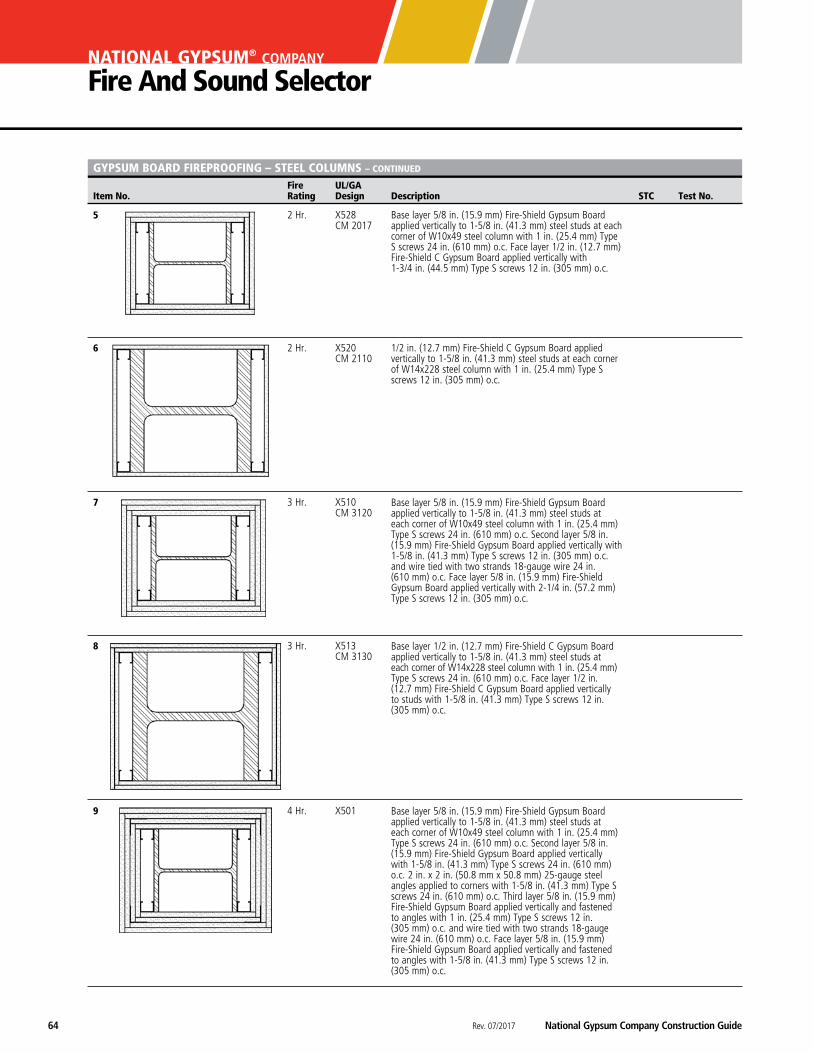
Rev. 07/2017 National Gypsum Company Construction Guide64
NATIONAL GYPSUM® COMPANY
Fire And Sound Selector
Fire UL/GA Item No. Rating Design Description STC Test No.
GYPSUM BOARD FIREPROOFING – STEEL COLUMNS – CONTINUED
5 2 Hr. X528 CM 2017
6 2 Hr. X520 CM 2110
7 3 Hr. X510 CM 3120
8 3 Hr. X513 CM 3130
9 4 Hr. X501
Base layer 5/8 in. (15.9 mm) Fire-Shield Gypsum Board applied vertically to 1-5/8 in. (41.3 mm) steel studs at each corner of W10x49 steel column with 1 in. (25.4 mm) Type S screws 24 in. (610 mm) o.c. Face layer 1/2 in. (12.7 mm) Fire-Shield C Gypsum Board applied vertically with 1-3/4 in. (44.5 mm) Type S screws 12 in. (305 mm) o.c.
1/2 in. (12.7 mm) Fire-Shield C Gypsum Board applied vertically to 1-5/8 in. (41.3 mm) steel studs at each corner of W14x228 steel column with 1 in. (25.4 mm) Type S screws 12 in. (305 mm) o.c.
Base layer 5/8 in. (15.9 mm) Fire-Shield Gypsum Board applied vertically to 1-5/8 in. (41.3 mm) steel studs at each corner of W10x49 steel column with 1 in. (25.4 mm) Type S screws 24 in. (610 mm) o.c. Second layer 5/8 in. (15.9 mm) Fire-Shield Gypsum Board applied vertically with 1-5/8 in. (41.3 mm) Type S screws 12 in. (305 mm) o.c. and wire tied with two strands 18-gauge wire 24 in. (610 mm) o.c. Face layer 5/8 in. (15.9 mm) Fire-Shield Gypsum Board applied vertically with 2-1/4 in. (57.2 mm) Type S screws 12 in. (305 mm) o.c.
Base layer 1/2 in. (12.7 mm) Fire-Shield C Gypsum Board applied vertically to 1-5/8 in. (41.3 mm) steel studs at each corner of W14x228 steel column with 1 in. (25.4 mm) Type S screws 24 in. (610 mm) o.c. Face layer 1/2 in. (12.7 mm) Fire-Shield C Gypsum Board applied vertically to studs with 1-5/8 in. (41.3 mm) Type S screws 12 in. (305 mm) o.c.
Base layer 5/8 in. (15.9 mm) Fire-Shield Gypsum Board applied vertically to 1-5/8 in. (41.3 mm) steel studs at each corner of W10x49 steel column with 1 in. (25.4 mm) Type S screws 24 in. (610 mm) o.c. Second layer 5/8 in. (15.9 mm) Fire-Shield Gypsum Board applied vertically with 1-5/8 in. (41.3 mm) Type S screws 24 in. (610 mm) o.c. 2 in. x 2 in. (50.8 mm x 50.8 mm) 25-gauge steel angles applied to corners with 1-5/8 in. (41.3 mm) Type S screws 24 in. (610 mm) o.c. Third layer 5/8 in. (15.9 mm) Fire-Shield Gypsum Board applied vertically and fastened to angles with 1 in. (25.4 mm) Type S screws 12 in. (305 mm) o.c. and wire tied with two strands 18-gauge wire 24 in. (610 mm) o.c. Face layer 5/8 in. (15.9 mm) Fire-Shield Gypsum Board applied vertically and fastened to angles with 1-5/8 in. (41.3 mm) Type S screws 12 in. (305 mm) o.c.
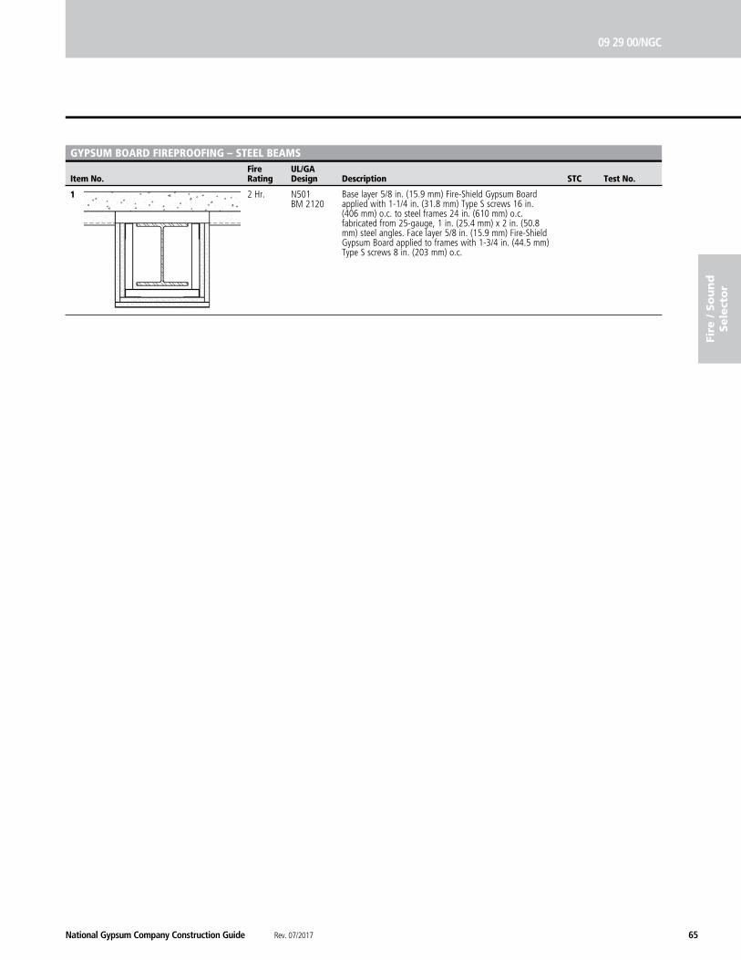
National Gypsum Company Construction Guide Rev. 07/2017 65
09 29 00/NGC
fire
/ S
ou
nd
Sele
cto
r
1 2 Hr. N501 BM 2120
Fire UL/GA Item No. Rating Design Description STC Test No.
GYPSUM BOARD FIREPROOFING – STEEL BEAMS
Base layer 5/8 in. (15.9 mm) Fire-Shield Gypsum Board applied with 1-1/4 in. (31.8 mm) Type S screws 16 in. (406 mm) o.c. to steel frames 24 in. (610 mm) o.c. fabricated from 25-gauge, 1 in. (25.4 mm) x 2 in. (50.8 mm) steel angles. Face layer 5/8 in. (15.9 mm) Fire-Shield Gypsum Board applied to frames with 1-3/4 in. (44.5 mm) Type S screws 8 in. (203 mm) o.c.
Rev. 07/2017 National Gypsum Company Construction Guide66
NATIONAL GYPSUM® COMPANY
Fire And Sound Selector
fire / S
ou
nd
Sele
ctor
NoTeS:
_________________________________________________________________________________________________________________
__________________________________________________________________________________________________________________________________________________________________________________________________________________________________________________________________________________________________________________________________________________________________________________________________________________________________________________________________________________________________________________________________________________________________________________________________________________________________________________________________________________________________________________________________________________________________________________________________________________________________________________________________________________________________________________________________________________________________________________________________________________________________________________________________________________________________________________________________________________________________________________________________________________________________________________________________________________________________________________________________________________________________________________________________________________________________________________________________________________________________________________________________________________________________________________________________________________________________________________________________________________________________________________________________________________________________________________________________________________________________________________________________________________________________________________________________________________________________________________________________________________________________________________________________________________________________________________________________________________________________________________________________________________________________________________________________________________________________________________________________________________________________________________________________________________________________________________________________________________________________________________________________________________________________________________________________________________________________________________________________________________________________________________________________________________________________________________________________________________________________________________________________