Finite Element Analysis of Horizontal ... · PDF fileFinite Element Analysis of Horizontal...
7
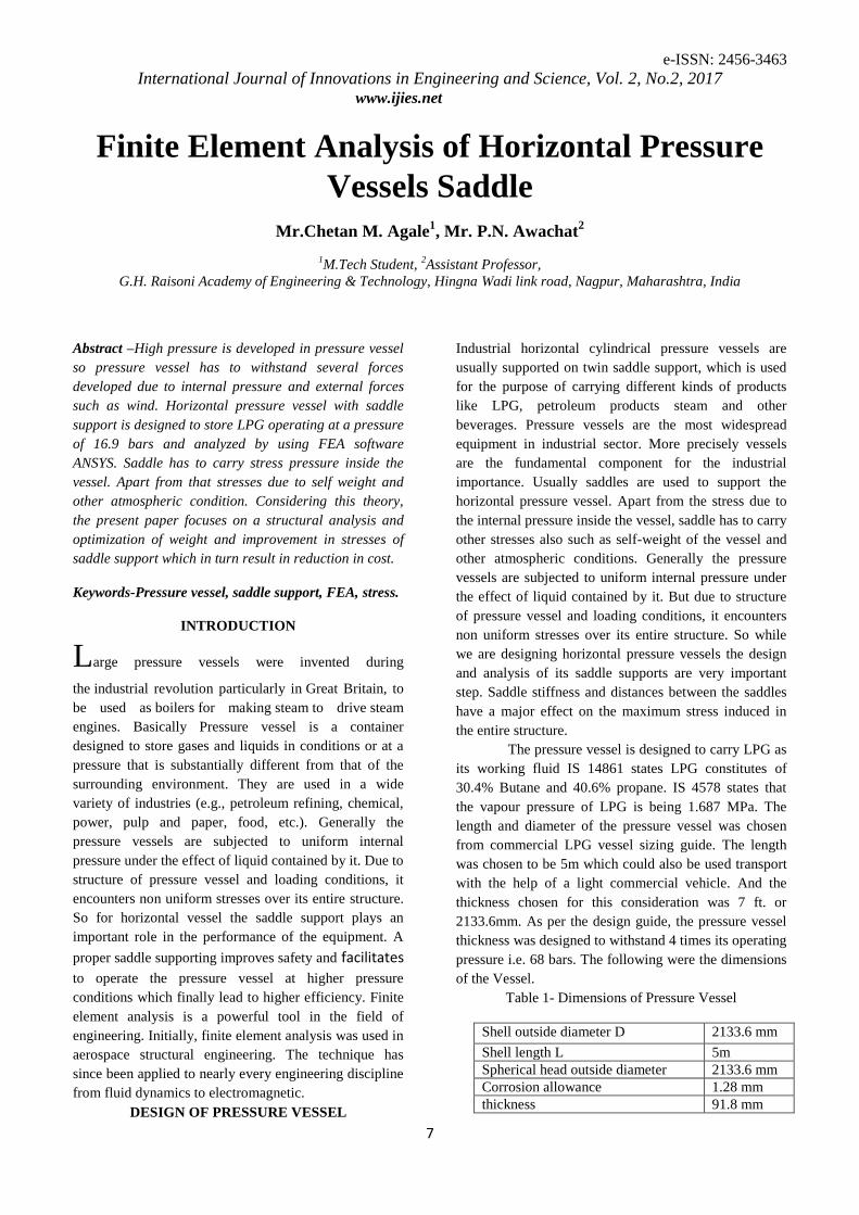
e-ISSN: 2456-3463 International Journal of Innovations in Engineering and Science, Vol. 2, No.2, 2017 www.ijies.net 7 Finite Element Analysis of Horizontal Pressure Vessels Saddle Mr.Chetan M. Agale 1 , Mr. P.N. Awachat 2 1 M.Tech Student, 2 Assistant Professor, G.H. Raisoni Academy of Engineering & Technology, Hingna Wadi link road, Nagpur, Maharashtra, India Abstract –High pressure is developed in pressure vessel so pressure vessel has to withstand several forces developed due to internal pressure and external forces such as wind. Horizontal pressure vessel with saddle support is designed to store LPG operating at a pressure of 16.9 bars and analyzed by using FEA software ANSYS. Saddle has to carry stress pressure inside the vessel. Apart from that stresses due to self weight and other atmospheric condition. Considering this theory, the present paper focuses on a structural analysis and optimization of weight and improvement in stresses of saddle support which in turn result in reduction in cost. Keywords-Pressure vessel, saddle support, FEA, stress. INTRODUCTION Large pressure vessels were invented during the industrial revolution particularly in Great Britain, to be used as boilers for making steam to drive steam engines. Basically Pressure vessel is a container designed to store gases and liquids in conditions or at a pressure that is substantially different from that of the surrounding environment. They are used in a wide variety of industries (e.g., petroleum refining, chemical, power, pulp and paper, food, etc.). Generally the pressure vessels are subjected to uniform internal pressure under the effect of liquid contained by it. Due to structure of pressure vessel and loading conditions, it encounters non uniform stresses over its entire structure. So for horizontal vessel the saddle support plays an important role in the performance of the equipment. A proper saddle supporting improves safety and facilitates to operate the pressure vessel at higher pressure conditions which finally lead to higher efficiency. Finite element analysis is a powerful tool in the field of engineering. Initially, finite element analysis was used in aerospace structural engineering. The technique has since been applied to nearly every engineering discipline from fluid dynamics to electromagnetic. DESIGN OF PRESSURE VESSEL Industrial horizontal cylindrical pressure vessels are usually supported on twin saddle support, which is used for the purpose of carrying different kinds of products like LPG, petroleum products steam and other beverages. Pressure vessels are the most widespread equipment in industrial sector. More precisely vessels are the fundamental component for the industrial importance. Usually saddles are used to support the horizontal pressure vessel. Apart from the stress due to the internal pressure inside the vessel, saddle has to carry other stresses also such as self-weight of the vessel and other atmospheric conditions. Generally the pressure vessels are subjected to uniform internal pressure under the effect of liquid contained by it. But due to structure of pressure vessel and loading conditions, it encounters non uniform stresses over its entire structure. So while we are designing horizontal pressure vessels the design and analysis of its saddle supports are very important step. Saddle stiffness and distances between the saddles have a major effect on the maximum stress induced in the entire structure. The pressure vessel is designed to carry LPG as its working fluid IS 14861 states LPG constitutes of 30.4% Butane and 40.6% propane. IS 4578 states that the vapour pressure of LPG is being 1.687 MPa. The length and diameter of the pressure vessel was chosen from commercial LPG vessel sizing guide. The length was chosen to be 5m which could also be used transport with the help of a light commercial vehicle. And the thickness chosen for this consideration was 7 ft. or 2133.6mm. As per the design guide, the pressure vessel thickness was designed to withstand 4 times its operating pressure i.e. 68 bars. The following were the dimensions of the Vessel. Table 1- Dimensions of Pressure Vessel Shell outside diameter D 2133.6 mm Shell length L 5m Spherical head outside diameter 2133.6 mm Corrosion allowance 1.28 mm thickness 91.8 mm
-
Upload
phungtuong -
Category
Documents
-
view
259 -
download
1
Transcript of Finite Element Analysis of Horizontal ... · PDF fileFinite Element Analysis of Horizontal...
e-ISSN: 2456-3463 International Journal of Innovations in Engineering and Science, Vol. 2, No.2, 2017
www.ijies.net
7
Finite Element Analysis of Horizontal Pressure
Vessels Saddle
Mr.Chetan M. Agale1, Mr. P.N. Awachat
2
1M.Tech Student,
2Assistant Professor,
G.H. Raisoni Academy of Engineering & Technology, Hingna Wadi link road, Nagpur, Maharashtra, India
Abstract –High pressure is developed in pressure vessel
so pressure vessel has to withstand several forces
developed due to internal pressure and external forces
such as wind. Horizontal pressure vessel with saddle
support is designed to store LPG operating at a pressure
of 16.9 bars and analyzed by using FEA software
ANSYS. Saddle has to carry stress pressure inside the
vessel. Apart from that stresses due to self weight and
other atmospheric condition. Considering this theory,
the present paper focuses on a structural analysis and
optimization of weight and improvement in stresses of
saddle support which in turn result in reduction in cost.
Keywords-Pressure vessel, saddle support, FEA, stress.
INTRODUCTION
Large pressure vessels were invented during
the industrial revolution particularly in Great Britain, to
be used as boilers for making steam to drive steam
engines. Basically Pressure vessel is a container
designed to store gases and liquids in conditions or at a
pressure that is substantially different from that of the
surrounding environment. They are used in a wide
variety of industries (e.g., petroleum refining, chemical,
power, pulp and paper, food, etc.). Generally the
pressure vessels are subjected to uniform internal
pressure under the effect of liquid contained by it. Due to
structure of pressure vessel and loading conditions, it
encounters non uniform stresses over its entire structure.
So for horizontal vessel the saddle support plays an
important role in the performance of the equipment. A
proper saddle supporting improves safety and facilitates
to operate the pressure vessel at higher pressure
conditions which finally lead to higher efficiency. Finite
element analysis is a powerful tool in the field of
engineering. Initially, finite element analysis was used in
aerospace structural engineering. The technique has
since been applied to nearly every engineering discipline
from fluid dynamics to electromagnetic.
DESIGN OF PRESSURE VESSEL
Industrial horizontal cylindrical pressure vessels are
usually supported on twin saddle support, which is used
for the purpose of carrying different kinds of products
like LPG, petroleum products steam and other
beverages. Pressure vessels are the most widespread
equipment in industrial sector. More precisely vessels
are the fundamental component for the industrial
importance. Usually saddles are used to support the
horizontal pressure vessel. Apart from the stress due to
the internal pressure inside the vessel, saddle has to carry
other stresses also such as self-weight of the vessel and
other atmospheric conditions. Generally the pressure
vessels are subjected to uniform internal pressure under
the effect of liquid contained by it. But due to structure
of pressure vessel and loading conditions, it encounters
non uniform stresses over its entire structure. So while
we are designing horizontal pressure vessels the design
and analysis of its saddle supports are very important
step. Saddle stiffness and distances between the saddles
have a major effect on the maximum stress induced in
the entire structure.
The pressure vessel is designed to carry LPG as
its working fluid IS 14861 states LPG constitutes of
30.4% Butane and 40.6% propane. IS 4578 states that
the vapour pressure of LPG is being 1.687 MPa. The
length and diameter of the pressure vessel was chosen
from commercial LPG vessel sizing guide. The length
was chosen to be 5m which could also be used transport
with the help of a light commercial vehicle. And the
thickness chosen for this consideration was 7 ft. or
2133.6mm. As per the design guide, the pressure vessel
thickness was designed to withstand 4 times its operating
pressure i.e. 68 bars. The following were the dimensions
of the Vessel.
Table 1- Dimensions of Pressure Vessel
Shell outside diameter D 2133.6 mm
Shell length L 5m
Spherical head outside diameter 2133.6 mm
Corrosion allowance 1.28 mm
thickness 91.8 mm

e-ISSN: 2456-3463 International Journal of Innovations in Engineering and Science, Vol. 2, No.2, 2017
www.ijies.net
8
Table 2- Material Properties
Property SA-516 GR.70
Density 7750 Kg/m3
Modulus of Elasticity 1.92E+11 N/m2
Poison ratio 0.3
Yield Strength 260 MPa
Operating pressure 1.69 MPa
Design Pressure 6.8 MPa
Operating temperature 297K
The vessel was modeled in CAD software as per the
design and the following figures show its modeling.
Fig 1.- CAD model dimensions
Fig. 2- CAD modeling
Now the saddle was designed for the loads applied by
the pressure vessel and the external environment such as
Wind loads. The baseline pressure vessel was designed
with the help of pressure vessel design manual and the
following are the parameter for the saddle.
Fig. 3- Saddle Dimensions
Table 3- Typical Saddle Dimensions
The baseline saddle was designed from the above table
and was designed in CAD with the following dimension
of the saddle.
Fig. 4- Dimension of the saddle
FORCES AND BOUNDARY CONDITIONS
The pressure vessel and saddle were designed to bear the
following loads:
A. Gravitational Forces:
The primary force which the saddle had to bear was the
gravitational forces arising due to the mass of pressure
vessel and LPG. The total mass carried by the saddles
was 42.25x10³ Kilograms
Fig. 5- Boundary Condition (Gravitational force)
e-ISSN: 2456-3463 International Journal of Innovations in Engineering and Science, Vol. 2, No.2, 2017
www.ijies.net
9
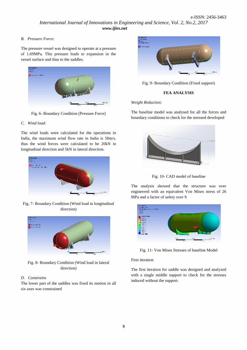
B. Pressure Force:
The pressure vessel was designed to operate at a pressure
of 1.69MPa. This pressure leads to expansion in the
vessel surface and thus to the saddles.
Fig. 6- Boundary Condition (Pressure Force)
C. Wind load:
The wind loads were calculated for the operations in
India, the maximum wind flow rate in India is 50m/s.
thus the wind forces were calculated to be 20kN in
longitudinal direction and 5kN in lateral direction.
Fig. 7- Boundary Condition (Wind load in longitudinal
direction)
Fig. 8- Boundary Condition (Wind load in lateral
direction)
D. Constrains
The lower part of the saddles was fixed its motion in all
six axes was constrained
Fig. 9- Boundary Condition (Fixed support)
FEA ANALYSIS
Weight Reduction:
The baseline model was analysed for all the forces and
boundary conditions to check for the stressed developed
Fig. 10- CAD model of baseline
The analysis showed that the structure was over
engineered with an equivalent Von Mises stress of 26
MPa and a factor of safety over 9
Fig. 11- Von Mises Stresses of baseline Model
First iteration
The first iteration for saddle was designed and analyzed
with a single middle support to check for the stresses
induced without the support.

e-ISSN: 2456-3463 International Journal of Innovations in Engineering and Science, Vol. 2, No.2, 2017
www.ijies.net
10
Fig. 12- CAD model of first iteration
Anequivalent Von Mises stress of 25 MPa and a factor
of safety over 9.5 suggested that the saddle was still over
engineered.
Fig. 13- Von Mises Stresses of first iteration
Second Iteration
The second iteration involved reduction of Saddle
support plates thickness from 9.53mm to 8.47mm to
check for the stresses induced.
Fig. 14- CAD model of second iteration
Anequivalent Von Mises stress of 25.4 MPa and a factor
of safety over 9.4 suggested that the saddle was still over
engineered to be used with the pressure vessel.
Fig.15- Von Mises Stresses of Second iteration
Third Iteration
Weight was reduced from the saddle by material
removal and optimization by slotting on the side
supports as they were carrying the minimum stresses.
Fig. 16- CAD model of third iteration
Anequivalent Von Mises stress of 39.5 MPa and a factor
of safety over 6 was obtained but the design was still
over engineered.
Fig. 17- Von Mises Stresses of third iteration
Fourth Iteration
Weight was again reduced from the saddle bymaterial
removal optimization by slotting on the side supports as
well as the main support where the stresses were
minimum.
Fig. 18- CAD model of fourth iteration
Anequivalent Von Mises stress of 39.7 MPa and a factor
of safety over 6 was obtained but the design was still
over engineered. So new approach was used in the
subsequent iterations for optimization.

e-ISSN: 2456-3463 International Journal of Innovations in Engineering and Science, Vol. 2, No.2, 2017
www.ijies.net
11
Fig. 19- Von Mises Stresses of fourth iteration
Shape optimization
The saddle was tried with some additional changes with
drastic reduction in the thickness of the side supports and
main support from 8.47mm to 6.35mm. The Baseline
model was formed with the following geometry.
Fig. 20- Dimension of the saddle for shape optimization
Baseline-
Fig. 21- CAD model of baseline
An equivalent Von Mises stress of 28 MPa and a factor
of safety over 8.4 was obtained but as the design was
still over engineered new iterations were again tried.
Fig. 22- Von Mises Stresses of baseline Model
First Iteration-
The saddle was tested with the 3 middle support to
improve the load carrying capacity and check the
stresses on the central column.
Fig. 23- CAD model of first iteration
Anequivalent Von Mises stress of 30.83 MPa and a
factor of safety about 7.8 was obtained but as the design
was still over engineered new iterations were again tried.
Fig. 24- Von Mises Stresses of first iteration
Second Iteration-
For the second iteration, saddle was tested with the
single middle support as shown in the below figure.
Fig. 25- CAD model of Second iteration
Anequivalent Von Mises stress of 32.1 MPa and a factor
of safety about 7.5 was obtained but as the design was
still over engineered new iterations were again tried.
Fig. 26- Von Mises Stresses of second iteration
e-ISSN: 2456-3463 International Journal of Innovations in Engineering and Science, Vol. 2, No.2, 2017
www.ijies.net
12
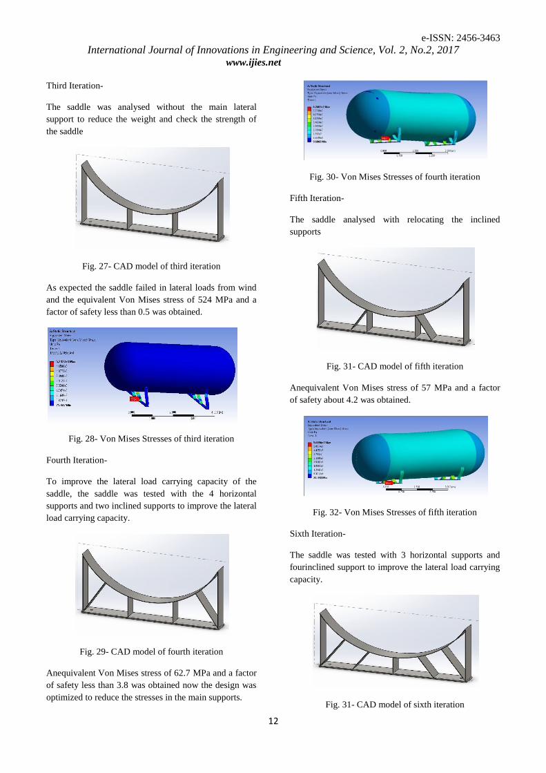
Third Iteration-
The saddle was analysed without the main lateral
support to reduce the weight and check the strength of
the saddle
Fig. 27- CAD model of third iteration
As expected the saddle failed in lateral loads from wind
and the equivalent Von Mises stress of 524 MPa and a
factor of safety less than 0.5 was obtained.
Fig. 28- Von Mises Stresses of third iteration
Fourth Iteration-
To improve the lateral load carrying capacity of the
saddle, the saddle was tested with the 4 horizontal
supports and two inclined supports to improve the lateral
load carrying capacity.
Fig. 29- CAD model of fourth iteration
Anequivalent Von Mises stress of 62.7 MPa and a factor
of safety less than 3.8 was obtained now the design was
optimized to reduce the stresses in the main supports.
Fig. 30- Von Mises Stresses of fourth iteration
Fifth Iteration-
The saddle analysed with relocating the inclined
supports
Fig. 31- CAD model of fifth iteration
Anequivalent Von Mises stress of 57 MPa and a factor
of safety about 4.2 was obtained.
Fig. 32- Von Mises Stresses of fifth iteration
Sixth Iteration-
The saddle was tested with 3 horizontal supports and
fourinclined support to improve the lateral load carrying
capacity.
Fig. 31- CAD model of sixth iteration

e-ISSN: 2456-3463 International Journal of Innovations in Engineering and Science, Vol. 2, No.2, 2017
www.ijies.net
13
An equivalent Von Mises stress of 49.2 MPa and a factor
of safety about 4.9 was obtained but and the design was
chosen as the best design in terms of weight and stress
characteristics to be used for this application.
Fig. 33- Von Mises Stresses of sixth iteration
CONCLUSION
The following pattern was observed from the Finite
element Analysis of the different saddles shapes.
Table 4- Saddle Weight reduction
Iteration Weight
( Kg)
Stress
( MPa) Factor of Safety
Baseline 172.5 26.07 9.20598389
1 168.3 24.80 9.677419355
2 165.9 25.39 9.45254037
3 164.0 39.45 6.08365019
4 161.8 39.70 6.04534005
The initial design from the design guide was quite
overdesigned having a factor of safety more than 6, so in
the subsequent designs the thickness of the plates used to
manufacture the saddle was reduced to 6.35mm and also
the main saddle plate was removed for further analysis.
Table 5- Saddle Topology optimization
Iteration Weight
( Kg)
Stress
(MPa)
Factor of Safety
Baseline 134.2 28.57 8.400420021
1 136.2 30.83 7.784625365
2 131.4 32.11 7.474307069
3 986.3 524.22 0.457823051
4 108.0 62.68 3.828972559
5 104.8 56.89 4.218667604
6 111.2 49.16 4.882017901
The final design provided a stress level of 49.2 MN/m2
with a factor of safety of 4.9, the weight was reduced
from 172.5 kg to 111.2 kg which corresponds to 35.5%
reduction in weight of the saddle.
REFERENCES
[1] Dennis R. Moss, Michael Basi, Pressure Vessel Design Manual
fourth edition, 2013.
[2] G. Ghanbari, M.A. Liaghat, Pressure Vessel Design, Guides and Procedures.
[3] SomnathChattopadhyay, Pressure Vessels Design and
Practice,CRC Press. [4] ASME Boiler and Pressure Vessel Code. Section VIII. Pressure
Vessels Division, 2. New York: ASME; (1989).
[5] Zick, L. P. "Stresses in large horizontal cylindrical pressure vessels on two saddle supports." Welding Journal Research
Supplement 30, no. 9 (1951): 435-445.
[6] Yang, L., C. Weinberger, and Y. T. Shah. "Finite element analysis on horizontal vessels with saddle supports." Computers &
structures 52, no. 3 (1994): 387-395.
[7] Aggarwal, S. K., and G. C. Nayak. "Elasto-plastic analysis as a basis for design of cylindrical pressure vessels with different end
closures." International Journal of Pressure Vessels and
Piping 10, no. 4 (1982): 271-296. [8] Tooth, Alwyn S., John ST Cheung, Heong W. Ng, Lin S. Ong, and
ChithranjanNadarajah. "An alternative way to support horizontal
pressure vessels subject to thermal loading." International journal of pressure vessels and piping 75, no. 8 (1998): 617-623.
[9] Khan, Shafique. "Stress distributions in a horizontal pressure
vessel and the saddle supports." International Journal of Pressure Vessels and Piping 87, no. 5 (2010): 239-244.
[10] Ong, L. S., and G. Lu. "Stress reduction factor associated with
saddle support with extended top plate." International journal of pressure vessels and piping62, no. 2 (1995): 205-208.
[11] Nash, D. H., and W. M. Banks. "Numerical analysis of a sling
support arrangement for GRP composite pressure vessels." Composite structures 38, no. 1 (1997): 679-687.
[12] Wang, Zhanghai, Daryl Bast, and David Shen. "Butane Storage Bullet Calculation and FEA Verification." In ASME 2005
Pressure Vessels and Piping Conference, pp. 307-313. American
Society of Mechanical Engineers, 2005.
DETAILS OF ALL AUTHORS
Sr.No Photo Details
1
M.Tech Student,
Department of Mechanical
Engineering, G.H. Raisoni
Academy of Engineering &
Technology, HingnaWadi
link road, Nagpur,
Maharashtra, India,
2
Assistant Professor,
Department of Mechanical
Engineering, G.H. Raisoni
Academy of Engineering &
Technology, HingnaWadi
link road, Nagpur,
Maharashtra, India,