Fielding DIXI - a new x-ray framing camera for the NIF - at JLF · 2013-04-05 · S.R. Nagel –...
30
Fielding DIXI - a new x-ray framing camera for the NIF - at JLF S.R. Nagel, P.M. Bell, D.K. Bradley, M.J. Ayers, B. Felker, K. Piston, J. Holder, G.W. Collins Lawrence Livermore National Laboratory T.J. Hilsabeck, J.D. Kilkenny, T. Chung General Atomics J.D. Hares, A.K.L. Dymoke-Bradshaw Kentech Instruments Ltd. J. Park, G.J. Williams, E.V. Marley, A.U. Hazi, H. Chen Lawrence Livermore National Laboratory S.M. Kerr University of Alberta Collaborators on TITAN experiment
Transcript of Fielding DIXI - a new x-ray framing camera for the NIF - at JLF · 2013-04-05 · S.R. Nagel –...

Fielding DIXI - a new x-ray framing camera for the NIF - at JLF
S.R. Nagel, P.M. Bell, D.K. Bradley, M.J. Ayers, B. Felker, K. Piston, J. Holder, G.W. Collins
Lawrence Livermore National Laboratory T.J. Hilsabeck, J.D. Kilkenny, T. Chung
General Atomics J.D. Hares, A.K.L. Dymoke-Bradshaw
Kentech Instruments Ltd.
J. Park, G.J. Williams, E.V. Marley, A.U. Hazi, H. Chen
Lawrence Livermore National Laboratory S.M. Kerr
University of Alberta
Collaborators on TITAN experiment
loredo1
Typewritten Text
LLNL-PRES-617852

S.R. Nagel – NIF and JLF User Group Meeting – February 2013
2
Summary
• Currently available x-ray framing cameras achieve gate times between 35 – 100 ps
• DIXI (Dilation x-ray imager) — is the fastest x-ray framing camera built to date (< 10ps) — DIXI achieves a higher temporal resolution by using the time
dilation concept — scheduled to be installed on NIF at the end of the summer
• Here we present — test and calibration measurements of the instrument taken at
the COMET laser — as well as data from a recent TITAN experiment, where we
have taken the first 2D time resolved (~ 7 ps) x-ray images of a target front surface during relativistic laser plasma interactions

S.R. Nagel – NIF and JLF User Group Meeting – February 2013
3
Outline
• NIF intended use • DIXI working principle • COMET testing
— Instrument characterization measurements • TITAN experiment
— The first 2D time resolved x-ray imaging of a target front surface during relativistic laser plasma interactions
• Summary
• JLF comments – improvement suggestions

S.R. Nagel – NIF and JLF User Group Meeting – February 2013
4
Currently gated imagers are used to show the shape of implosion and measure bang time (peak x-ray emission) on NIF
GXD1 0-0 Corrected Image
Obviously there are many other applications for framing cameras
S.R. Nagel – NIF and JLF User Group Meeting – February 2013
5
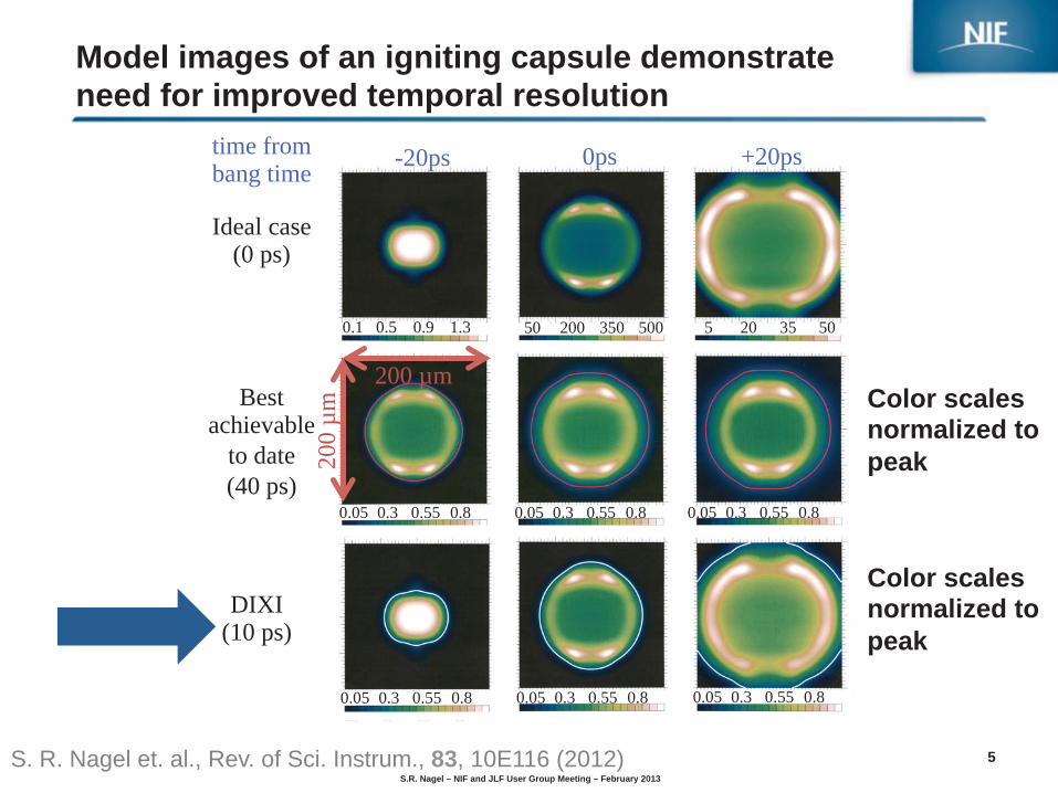
Model images of an igniting capsule demonstrate need for improved temporal resolution
S. R. Nagel et. al., Rev. of Sci. Instrum., 83, 10E116 (2012)
-20ps 0ps +20ps
DIXI (10 ps)
Best achievable
to date (40 ps)
Ideal case (0 ps)
time from bang time
200
µm
0.8 0.55 0.3 0.05 0.8 0.55 0.3 0.05 0.8 0.55 0.3 0.05
0.8 0.55 0.3 0.05 0.8 0.55 0.3 0.05 0.8 0.55 0.3 0.05
500 350 200 50 50 35 20 5 1.3 0.9 0.5 0.1
200 µm Color scales normalized to peak
Color scales normalized to peak

S.R. Nagel – NIF and JLF User Group Meeting – February 2013
6
Dilation x-ray imager (DIXI) uses pulse-dilation to provide better temporal resolution than currently available
Photoelectrons accelerated by a time varying electric field energy dispersion signal stretches as it traverses the drift region sampled by gated mcp
anode mesh
photo cathode
hv pulser
x-rays electrons
drift space
~ 50 × pulse dilation
incoming photon signal
gated mcp 200ps
Initial signal width dilated signal width
B-field lines
ga
2
S. R. Nagel et. al., Rev. of Sci. Instrum., 83, 10E116 (2012) T.J. Hilsabeck et al., Rev. of Sci. Instrum., 81, 10E317 (2010)

S.R. Nagel – NIF and JLF User Group Meeting – February 2013
7
Four parameters determine the effective shutter speed of DIXI
mcp gate
anode mesh
photo cathode
hv pulser
incoming photon signal
m
dilated signal width
~ 50 × pulse dilation
Initial signal width
x-rays electrons B-field lines
esh
drift space
Parameter Determines 1. PC bias voltage “mean” velocity of electrons 2. Gradient of fast PC pulse Electron dispersion 3. Drift length time for pulse dilation 4. MCP gate width how much is collected
rayyyyyyyyyyyyyyyyssssssssssss eeeele1 d
3 4
2

S.R. Nagel – NIF and JLF User Group Meeting – February 2013
8
DIXI – dilation x-ray imager consists of photocathode, drift space and back end (mcp and phosphor)
4 strips on PC strip length ~400ps
12cm long, 15.5mm wide
active area 12 cm
drift length 50 cm
magnet coils
mcp detector and
phosphor window ccd
photocathode (PC)
B-field reduces image 3x

S.R. Nagel – NIF and JLF User Group Meeting – February 2013
9
Planned operation on the NIF puts DIXI outside the target chamber
• This leads to a large magnification of the images
• As well as a low photon flux at the detector
ebruary 2013

S.R. Nagel – NIF and JLF User Group Meeting – February 2013
10
We have tested the DIXI using a short x-ray pulse, which was produced using the COMET laser
τ
• The x-ray source had an unobstructed path to the instruments. • Strips were co-timed
S.R. Nagel – NIF and JLF User Group Meeting – February 2013
11
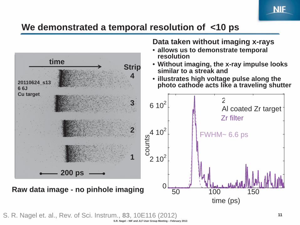
We demonstrated a temporal resolution of <10 ps
Raw data image - no pinhole imaging
20110624_s13 6 6J Cu target
Strip 4 3 2
1
time
200 ps
0
2 102
4 102
6 102
50 100 150
coun
ts
time (ps)
Zr filter
20110802_s4Al coated Zr target
FWHM~ 6.6 ps
S. R. Nagel et. al., Rev. of Sci. Instrum., 83, 10E116 (2012)
Data taken without imaging x-rays • allows us to demonstrate temporal
resolution • Without imaging, the x-ray impulse looks
similar to a streak and • illustrates high voltage pulse along the
photo cathode acts like a traveling shutter

S.R. Nagel – NIF and JLF User Group Meeting – February 2013
12
103
104
1 103 2 103 3 103 4 103 5 103
DIX
I am
plitu
de (c
nts)
GXD amplitude (cnts)
0.001
0.01
0.1
1
10
-200 -100 0 100 200S
igna
l (a.
u.)
mcp bias (V)
GXD was used as a reference detector at COMET and the two cameras show a linear correlation
∝ V 23.7
The Signal level can be varied by three orders of magnitude by varying the MCP gain
Linear correlation between GXD and DIXI signal with DIXI showing a higher signal level
Instrument comparison Gain – Voltage relation
DIXI=GXD
linear fit

S.R. Nagel – NIF and JLF User Group Meeting – February 2013
13
We can easily adjust the effective gate time of DIXI and optimize the gain if signal starved
PC bias1530 V750 V
Expected change with increasing PC bias due to effect on dilation: • Increase in signal level ~2.8 • Broadening of signal
Higher PC Voltage – longer gate – more signal
0
0.2
0.4
0.6
0.8
1
140 160 180 200 220no
rmal
ized
cou
nts
time (ps)
15.3 ps8.1 ps
FWHM
0
1
2
3
4
140 160 180 200 220
Sig
nal (
a.u.
)ad
just
ed fo
r ref
eren
ce d
iagn
ostic
an
d M
CP
bia
s of
fset
time (ps)

S.R. Nagel – NIF and JLF User Group Meeting – February 2013
14
No observed droop along strips – significant improvement vs. MCP based gated x-ray imagers
012345678
0 50 100 150 200 250 300 350
Sig
nal (
a.u.
)
position (ps)
strip 4 + offset
strip 3 + offset
strip 2 + offset
strip 1
No droop due to separation into PC and a single strip MCP with wide gate
GXD – example droop
0
1 103
2 103
3 103
4 103
5 103
-50 0 50 100 150 200 250 300
GX
D s
igna
l (a.
u.)
time (ps)
strip 4
strip 3
strip 2
strip 1
DIXI – signal walked along strips

S.R. Nagel – NIF and JLF User Group Meeting – February 2013
15
Spatial resolution of DIXI is a function of the B-field and the spatial resolutions of the PC & MCP
• δPC depends on the material of the PC and the magnetic field
strength at its position
• Secondary photoelectrons are ejected with a characteristic energy spread depending on the PC material
• CsI has a characteristic energy spread of 1.7 eV, compared to Au at 3.5 eV
δinstr =√
δ2PC + (δmcp ×MagB)2
4rL[μm] = 95000
√Te[eV ]
B[Gauss]
T.J. Hilsabeck et al., Rev. of Sci. Instrum., 81, 10E317 (2010)

S.R. Nagel – NIF and JLF User Group Meeting – February 2013
16
We can meet the spatial resolution requirements for operation on the NIF
200
250
300
350
400
450
500
550
300 400 500 600 700 800
δ inst
r at P
C (µ
m)
Magnetic field at PC (Gauss)
Au
CsI
TheoryMeasurements
Comparing measured with theoretical δinstr shows good agreement

S.R. Nagel – NIF and JLF User Group Meeting – February 2013
17
DIXI is fastest x-ray framing camera with improved performance compared to existing diagnostics
• DIXI has a temporal resolution <10 ps • Control over effective shutter speed and
signal amplitude • Brighter than GXD at same conditions • Similar mcp gain factor – 3x for 50 V bias
change • No systematic signal droop along PC strips • Using CsI not only gives a better QE but also
results in a better spatial resolution of the instrument
0
2 102
4 102
6 102
50 100 150
coun
ts
time (ps)
Zr filter
20110802_s4Al coated Zr target
FWHM~ 6.6 ps
so
0.001
0.01
0.1
1
10
-200 -100 0 100 200
Sig
nal (
a.u.
)
mcp bias (V)
∝ V 23.7
012345678
0 50 100 150 200 250 300 350
Sig
nal (
a.u.
)position (ps)
strip 4 + offset
strip 3 + offset
strip 2 + offset
strip 1
Summary – COMET data
We have now started taking real data on TITAN experiment(s)

S.R. Nagel – NIF and JLF User Group Meeting – February 2013
18
Pinhole at 4.8 cm from tcc
TITAN laser 0.5-1 ps 100 J 20 µm FWHM
Target
At TITAN we are imaging the x-ray emission from the front side of short pulse laser plasma interactions
DC image of PH array Mag ~40x
77 µm 67 µm
pinhole imaging with • magnification of ~ 40 x and • temporal gate width of 7ps
DIXI ~2 m from tcc

S.R. Nagel – NIF and JLF User Group Meeting – February 2013
19
0
0.2
0.4
0.6
0.8
1
0
0.2
0.4
0.6
0.8
1
0 5 10 15 20
QE
Transmission of filter
keV
effect of TITAN filtering
0
0.2
0.4
0.6
0.8
1
0
0.2
0.4
0.6
0.8
1
0 5 10 15 20
QE
Transmission of filter
keV
effect of TITAN filtering
TiKαHeα
Lα1Lα2Lβ1
KβLyα
0
0.2
0.4
0.6
0.8
1
0
0.2
0.4
0.6
0.8
1
0 5 10 15 20
QE
Transmission of filter
keV
effect of TITAN filtering
Au
Lα1Lα2
Lβ2Lβ1 Lγ2
Ll
Mα
Our filtering picks out different features for different target materials

S.R. Nagel – NIF and JLF User Group Meeting – February 2013
20
500 1000 1500 2000 2500 3000 3500 4000
500
1000
1500
2000
2500
3000
3500
4000
Strip 1Strip 4 Strip 2Strip 3
time
19 ps
Example image showing evolution of x-ray emission with 7 ps temporal resolution
pix
pix
μm
μm
100 200 300 400 500 600 700
100
200
300
400
500
600
700
800
12 ps
31 ps
50 ps
69 ps
Cropped image and parallax taken out
88 ps
Ti target
0 ps

S.R. Nagel – NIF and JLF User Group Meeting – February 2013
21
Ti – no injection
s29, q13, strip2 dt=12ps
50 100 150 200 250
50
100
150
1 2 3 4 5 6
x 104
t = 12 ps
μm
s29, q20, strip2 dt=71ps
50 100 150 200 250
50
100
150
1000 1500 2000 2500 3000
t = 71 ps
μm
s26, q6, strip2 dt=18ps
50 100 150 200 250
50
100
150
1000 2000 3000 4000 5000 6000 7000
s26, q4, strip2 dt=3ps
50 100 150 200 250
50
100
150
0.5 1 1.5 2 2.5 3
x 104
t = 3 ps
μm
t = 18 ps
μm
Au – no injection
Note: Au emission also does not last as long
observations At the start the Au emission is similar in shape and size, compared to Ti, but later emission is larger and non-symmetric

S.R. Nagel – NIF and JLF User Group Meeting – February 2013
22
Injection of 3 ns pre-pulse changed x-ray emission characteristics – shown here for Au target
s41, q7, strip2 dt=5ps
50 100 150 200 250
50
100
150
1000 2000 3000 4000 5000 6000 7000
s41, q8, strip2 dt=22ps
50 100 150 200 250
50
100
150
500 1000 1500 2000
s26, q6, strip2 dt=18ps
50 100 150 200 250
50
100
150
1000 2000 3000 4000 5000 6000 7000
s26, q4, strip2 dt=3ps
50 100 150 200 250
50
100
150
0.5 1 1.5 2 2.5 3
x 104
t = 3 ps
μm
t = 5 ps
μm
t = 22 ps
μm
t = 18 ps
μm
50 mJ, 3 ns pre-pulse injected No injected pre-pulse – only ASE
/ ~1.8
/ ~1.8
observations

S.R. Nagel – NIF and JLF User Group Meeting – February 2013
23
Injection of 3 ns pre-pulse also changed x-ray emission characteristics – for Titanium target
s29, q13, strip2 dt=12ps
50 100 150 200 250
50
100
150
1 2 3 4 5 6
x 104
t = 12 ps
μm
s33, q5, strip3 dt=15ps
50 100 150 200 250
50
100
150
2000 4000 6000 8000
x ~2
t = 15 ps
μm
s33, q11, strip2 dt=41ps
50 100 150 200 250
50
100
150
600 800 1000 1200 1400 1600 1800
t = 41 ps
μm
s29, q20, strip2 dt=71ps
50 100 150 200 250
50
100
150
1000 1500 2000 2500 3000
t = 71 ps
μm
50 mJ, 3 ns pre-pulse injected No injected pre-pulse – only ASE
observations

S.R. Nagel – NIF and JLF User Group Meeting – February 2013
24
Magnetic fields are under investigation as a possible cause for the observed change in x-ray emission shape
• 50 mJ 3ns injected pulse — Channel formation in pre-plasma — Magnetic field inside channel from
electrons moving with laser — Magnetic field outside the channel
due to grad Te x grad ne — Channel expansion after laser turn
off
• No injection — no significant channel formation
and expansion
[1]
[1] Borghesi et al., PRL, 80, 5137 (1998), Figure 1
50 100 150 200 250
50
100
150
q p p
50 100 150 200 250
50
100
150

S.R. Nagel – NIF and JLF User Group Meeting – February 2013
25
s29, q23, strip2 dt=92ps
50 100 150 200 250
50
100
150
500 1000 1500 2000
s29, q20, strip2 dt=71ps
50 100 150 200 250
50
100
150
1000 1500 2000 2500 3000
s29, q13, strip2 dt=12ps
50 100 150 200 250
50
100
150
1 2 3 4 5 6
x 104
s29, q1, strip1 dt=4ps
50 100 150 200 250
50
100
150
1 2 3 4 5 6
x 104
No injection emission for Titanium target is very long and stays very round and confined
s29, q22, strip2 dt=−6ps
50 100 150 200 250
50
100
150
600 800 1000 1200 1400 1600
s29, q17, strip2 dt=33ps
50 100 150 200 250
50
100
150
500 1000 1500 2000 2500 3000
t = -6 ps t = 4 ps
t = 33 ps t = 71 ps
t = 12 ps
t = 92 ps
μm
μmμm μm
μm μm
observations

S.R. Nagel – NIF and JLF User Group Meeting – February 2013
26
s33, q11, strip2 dt=41ps
50 100 150 200 250
50
100
150
600 800 1000 1200 1400 1600 1800
s33, q6, strip1 dt=34ps
50 100 150 200 250
50
100
150
500 1000 1500 2000 2500 3000
s33, q5, strip3 dt=15ps
50 100 150 200 250
50
100
150
2000 4000 6000 8000
s33, q7, strip2 dt=2ps
50 100 150 200 250
50
100
150
1 2 3 4 5
x 104
50 mJ 3 ns injected pre-pulse shot shows shows larger, less defined spot and less emission
s33, q4, strip3 dt=−1ps
50 100 150 200 250
50
100
150
500 1000 1500 2000 2500 3000 3500
s33, q9, strip2 dt=19ps
50 100 150 200 250
50
100
150
2000 4000 6000 8000
x ~2 x ~2
t = -1 ps t = 2 ps
t = 19 ps t = 34 ps
t = 15 ps
t = 41 ps
μm
μmμm μm
μm μm
observations

S.R. Nagel – NIF and JLF User Group Meeting – February 2013
27
Injected pre-pulse does not affect the time of integrated peak emission per frame
Preliminary analysis suggests:
• Emission peaks at
the same time • With injection the
peak emission is not as bright but longer
• However, extended measurable emission for “clean” case (may be due to long lived He-alpha emission)
• Could be due to magnetic field effects and electron dynamics changing due to pre-plasma effects
Next experiment, we will use a tighter spaced pinhole set to obtain more frames with less temporal separation and gather more insight.
0
1 103
2 103
3 103
-20 0 20 40 60 80 100inte
grat
ed c
ount
s no
rm to
win
dow
siz
e
time (ps)
with injected pre-pulse
s29 Ti no injections33 Ti 50 mJ injection
S.R. Nagel – NIF and JLF User Group Meeting – February 2013
28
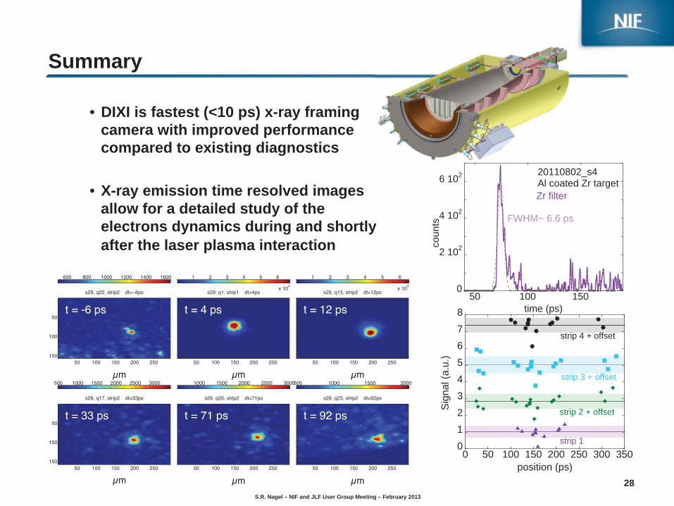
Summary
• DIXI is fastest (<10 ps) x-ray framing camera with improved performance compared to existing diagnostics
• X-ray emission time resolved images allow for a detailed study of the electrons dynamics during and shortly after the laser plasma interaction
s29, q23, strip2 dt=92ps
50 100 150 200 250
50
100
150
500 1000 1500 2000
s29, q20, strip2 dt=71ps
50 100 150 200 250
50
100
150
1000 1500 2000 2500 3000
s29, q13, strip2 dt=12ps
50 100 150 200 250
50
100
150
1 2 3 4 5 6
x 104
s29, q1, strip1 dt=4ps
50 100 150 200 250
50
100
150
1 2 3 4 5 6
x 104
s29, q22, strip2 dt=−6ps
50 100 150 200 250
50
100
150
600 800 1000 1200 1400 1600
s29, q17, strip2 dt=33ps
50 100 150 200 250
50
100
150
500 1000 1500 2000 2500 3000
t = -6 ps t = 4 ps
t = 33 ps t = 71 ps
t = 12 ps
t = 92 ps
μm
μmμm μm
μm μm
0
2 102
4 102
6 102
50 100 150
coun
ts
time (ps)
Zr filter
20110802_s4Al coated Zr target
FWHM~ 6.6 ps
012345678
0 50 100 150 200 250 300 350S
igna
l (a.
u.)
position (ps)
strip 4 + offset
strip 3 + offset
strip 2 + offset
strip 1
S.R. Nagel – NIF and JLF User Group Meeting – February 2013
29
Improvement suggestions for JLF
• Pre-pulse improvement esp. for TITAN • Laser diagnostics installation and maintenance as standard in all
TA. — Monitoring pulse duration, near and far field, pre-pulse, energy
• 2nd near PW short pulse beam capability for TITAN
• Everyone is working really hard for the users, and we are aware that the facility is understaffed! Ideally more staff would be available to for example support during maintenance periods, or to prepare equipment for maintenance periods.