Fieldbus Isolating Repeater - r-stahl.com · 2 Fieldbus Isolating Repeater Series 9185 EN EN EN EN...
26
EN EN EN EN EN EN EN EN EN EN EN EN EN EN EN EN EN EN EN EN EN EN EN EN EN Manual Additional languages www.stahl-ex.com EN Fieldbus Isolating Repeater Series 9185
Transcript of Fieldbus Isolating Repeater - r-stahl.com · 2 Fieldbus Isolating Repeater Series 9185 EN EN EN EN...

ENENENENENENENENENENENENENENENENEN
ManualAdditional languages www.stahl-ex.com
EN
ENENENENENENENEN
Fieldbus Isolating Repeater
Series 9185

ENENENENENENENENENENENENENENENENENENENENENENENENEN
Contents1 General Information ............................................................................................31.1 Manufacturer .......................................................................................................31.2 Information about the manual .............................................................................31.3 Further documents ..............................................................................................31.4 Conformity with standards and regulations .........................................................32 Explanation of the symbols .................................................................................32.1 Symbols used in this manual ..............................................................................32.2 Warning notes .....................................................................................................42.3 Symbols on the device ........................................................................................43 Safety notes ........................................................................................................53.1 Storage of the manual .........................................................................................53.2 Safe use ..............................................................................................................53.3 Modifications and alterations ..............................................................................64 Function and device design ................................................................................64.1 Function ..............................................................................................................64.2 Device design .....................................................................................................75 Technical data .....................................................................................................96 Engineering .......................................................................................................147 Transport and storage .......................................................................................148 Mounting and installation ..................................................................................158.1 Dimensions / fastening dimensions ..................................................................158.2 Mounting / dismounting, operating position ......................................................168.3 Installation .........................................................................................................169 Parameterization and commissioning ...............................................................209.1 Replacement of the device ...............................................................................219.2 Overview of functions ........................................................................................219.3 DIP switch settings 9185/11-35-10 ...................................................................219.4 DIP switch settings 9185/11-45-10 ...................................................................229.5 DIP switch settings 9185/12-45-10 ...................................................................239.6 "BAUD" decode switch for setting the transmission speed ...............................2310 Operation ..........................................................................................................2410.1 Operation ..........................................................................................................2410.2 Indications .........................................................................................................2410.3 Troubleshooting ................................................................................................2511 Maintenance and repair ....................................................................................2511.1 Maintenance .....................................................................................................2511.2 Maintenance .....................................................................................................2611.3 Repair ...............................................................................................................2611.4 Returning the device .........................................................................................2612 Cleaning ............................................................................................................2613 Disposal ............................................................................................................2614 Accessories and Spare parts ...........................................................................26
2 Fieldbus Isolating RepeaterSeries 9185

General Information ENENENENENENENENENENENENENENENENENENENENENENENENEN
1 General Information
1.1 ManufacturerR. STAHL Schaltgeräte GmbHAm Bahnhof 3074638 Waldenburg Germany
Phone: +49 7942 943-0Fax: +49 7942 943-4333Internet: www.stahl-ex.comE-Mail: [email protected]
1.2 Information about the manualID-No.: 9185602330Publication Code: 2016-04-15·HB00·III·en·03Hardware version: ESoftware version: 01-04
1.3 Further documents• Data sheet 9185• Operating instructions 9185For documents in further languages, see www.stahl-ex.com.
1.4 Conformity with standards and regulationsSee certificates and EU Declaration of Conformity: www.stahl-ex.com.The device has IECEx approval. See IECEx homepage: http://iecex.iec.ch/Further national certificates can be downloaded via the following link: http://www.r-stahl.com/downloads/certificates.html.
2 Explanation of the symbols
2.1 Symbols used in this manualSymbol Meaning
Tips and recommendations on the use of the device
Danger due to explosive atmosphere
91856023302016-04-15·HB00·III·en·03
3Fieldbus Isolating RepeaterSeries 9185
Explanation of the symbolsENENENENENENENENENENENENENENENENENENENENENENENENEN
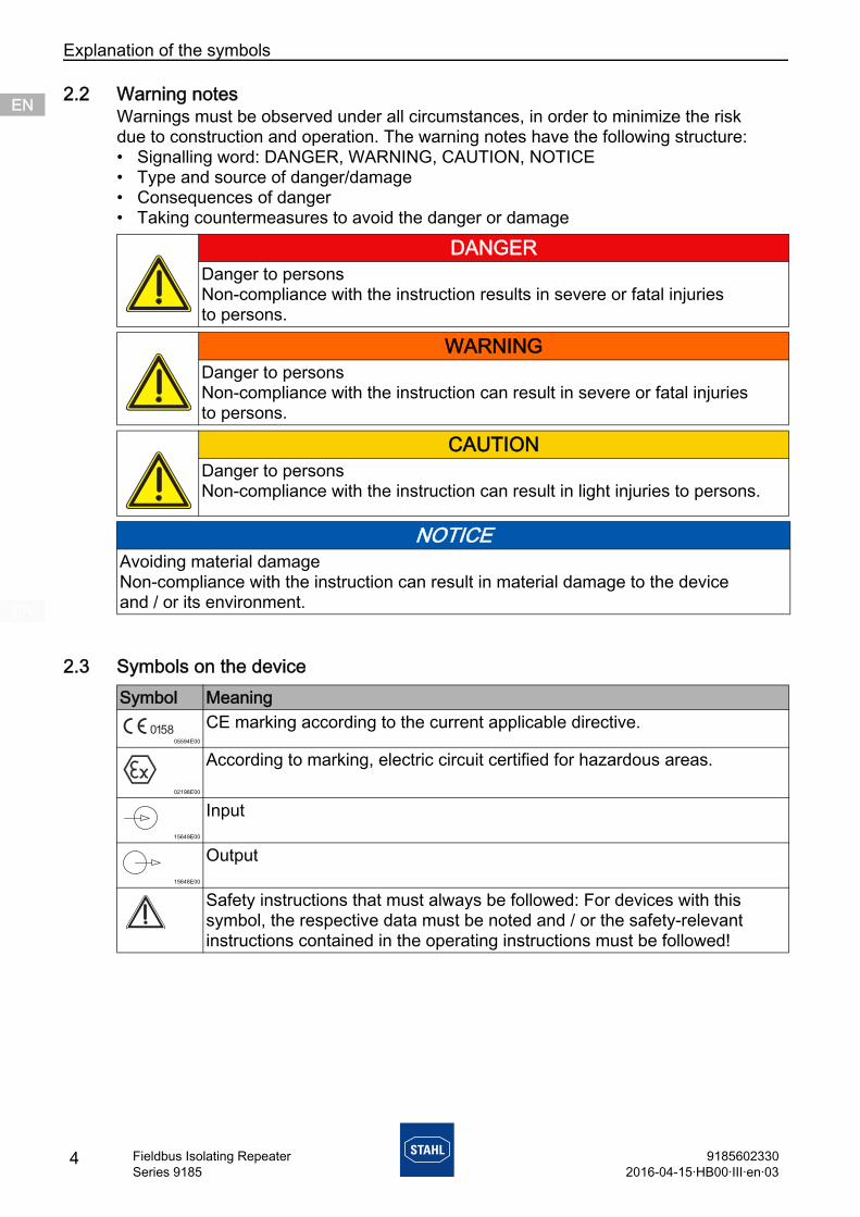
2.2 Warning notesWarnings must be observed under all circumstances, in order to minimize the risk due to construction and operation. The warning notes have the following structure:• Signalling word: DANGER, WARNING, CAUTION, NOTICE• Type and source of danger/damage• Consequences of danger• Taking countermeasures to avoid the danger or damage
2.3 Symbols on the device
DANGERDanger to personsNon-compliance with the instruction results in severe or fatal injuries to persons.
WARNINGDanger to personsNon-compliance with the instruction can result in severe or fatal injuries to persons.
CAUTIONDanger to personsNon-compliance with the instruction can result in light injuries to persons.
NOTICEAvoiding material damageNon-compliance with the instruction can result in material damage to the device and / or its environment.
Symbol Meaning
05594E00
CE marking according to the current applicable directive.
02198E00
According to marking, electric circuit certified for hazardous areas.
15649E00
Input
15648E00
Output
Safety instructions that must always be followed: For devices with this symbol, the respective data must be noted and / or the safety-relevant instructions contained in the operating instructions must be followed!
4 91856023302016-04-15·HB00·III·en·03
Fieldbus Isolating RepeaterSeries 9185

Safety notes ENENENENENENENENENENENENENENENENENENENENENENENENEN
3 Safety notes
3.1 Storage of the manual• Read the manual carefully.• Store the manual at the mounting location of the device.• Observe applicable documents and operating instructions of the devices
to be connected.
3.2 Safe useBefore mounting• Read and observe the safety notes in this manual.• Ensure that the contents of this manual are fully understood by the personnel
in charge.• Use the device in accordance with its intended and approved purpose only.• Always consult with R. STAHL Schaltgeräte GmbH if using the device under operating
conditions which are not covered by the technical data.• Observe the document "Cabinet installation guide" for engineering (download from
www.stahl-ex.com, product documentation, subitem "Engineering").• Before installation, make sure that the device is not damaged.• We cannot be held liable for damage caused by incorrect or unauthorised use
of the device or by non-compliance with this manual.
For assembly and installation• Observe national assembly and installation regulations (e.g. IEC/EN 60079-14).• Observe national safety and accident prevention regulations.• During installation and operation, observe the information (characteristic values and
rated operating conditions) on the type plates and data plates and information signs located on the device.
• Install the device in Zones 2, 22 or outside of hazardous areas.• When used in Zones 2 or 22, the device must be built into an enclosure which
corresponds to the requirements of IEC/EN 60079-15 or IEC/EN 60079-31.• Electric circuits with the "Ex i" type of protection operated with circuits with other types
of protection can no longer be operated as circuits with the "Ex i" type of protection after this stage.
• Connect the device only to equipment which does not carry voltages higher than 253 V AC (50 Hz).
• The safety characteristic values of the connected field devices must correspond to the specifications in the data sheet or in the EC Type Examination Certificate.
• Interconnecting several devices in a single intrinsically safe circuit can result in different safety characteristic values. This may impair intrinsic safety!
91856023302016-04-15·HB00·III·en·03
5Fieldbus Isolating RepeaterSeries 9185
Function and device designENENENENENENENENENENENENENENENENENENENENENENENENEN
Maintenance, repair, commissioning• Before commissioning, make sure that the device is not damaged.• Work on the device, such as installation, maintenance, overhaul, repair,
may only be carried out by appropriately authorised and trained personnel.• Perform only maintenance work or repair described in this manual.• Changing the DIP switch settings is also permitted during operation in Zone 2
and with connected intrinsically safe input signals.• Set up the power supply for 24 V DC so that it can so bridge interruptions of 20 ms
(power failure bridging in accordance with EN 61326-3-2 and NE 21).• The devices must be installed in enclosures which comply with the requirements
of the installation location.• 9185/11 only: Intrinsically safe Zone 1 devices can be connected to the intrinsically
safe signal circuits.• Intrinsically safe signal circuits must not be connected to the fieldbus isolating repeater
9185/12.
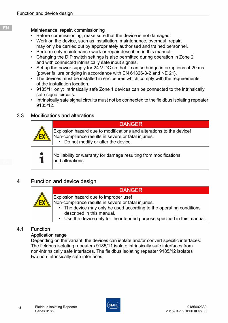
3.3 Modifications and alterations
4 Function and device design
4.1 FunctionApplication rangeDepending on the variant, the devices can isolate and/or convert specific interfaces. The fieldbus isolating repeaters 9185/11 isolate intrinsically safe interfaces from non-intrinsically safe interfaces. The fieldbus isolating repeater 9185/12 isolates two non-intrinsically safe interfaces.
DANGERExplosion hazard due to modifications and alterations to the device! Non-compliance results in severe or fatal injuries.
• Do not modify or alter the device.
No liability or warranty for damage resulting from modifications and alterations.
DANGERExplosion hazard due to improper use!Non-compliance results in severe or fatal injuries.
• The device may only be used according to the operating conditions described in this manual.
• Use the device only for the intended purpose specified in this manual.
6 91856023302016-04-15·HB00·III·en·03
Fieldbus Isolating RepeaterSeries 9185

Function and device design ENENENENENENENENENENENENENENENENENENENENENENENENEN
VariantsThe fieldbus isolating repeater 9185/11-35-10 is used to isolate an intrinsically safe RS-485 interface from a non-intrinsically safe RS-232, RS-422 or RS-485. The device is suitable for the operation of intrinsically safe PROFIBUS DP or Modbus RTU. Using galvanic isolation and the "bit refresh" function, the isolating repeater 9185/12-4.-10 ensures the interference-free transmission of Profibus, Modbus and R. STAHL ServiceBus signals.
Mode of operationThe isolating repeater blocks any equalisation currents and protects sensitive devices against transient noise. The device supports both RS-485 and RS-422 systems. In addition, it can adapt RS-232 interfaces to RS-485 or RS-422. This enables standard PCs to be connected to RS-485 or RS-422 interfaces. Converting to RS-485 or RS-422 means that transmission systems connected to RS-232 can achieve larger transmission distances.
4.2 Device designType 9185/11-35-10# # Device component Description
08624E00
1 Safe area interface
X1: RS-232X2: RS-422, RS-4857 (+), 9 (-): Auxiliary power connection¿: equipotential bonding connection
2 "BAUD" decode switch
Setting the baud rate for the bus interface
3 "SCAN" DIP switch
ON: RS-422 spring returnOFF: RS-422 permanently ON
4 "RS2" DIP switch ON: X2 = RS-422OFF: X2 = RS-485
5 "PNO" DIP switch ON: Signal Level PNOOFF: Signal Level STAHL
6 Field-side interface
X3: RS-485 IS
7 "RxD3" LED, green
Reception interface X3
8 "RxD2" LED, green
Reception interface X2
9 "RxD1" LED, green
Reception interface X1
10 "ERR" LED, red Error message/baud rate search11 "PWR" LED, green Auxiliary power display
1110
987
345
6
1
2
91856023302016-04-15·HB00·III·en·03
7Fieldbus Isolating RepeaterSeries 9185

Function and device designENENENENENENENENENENENENENENENENENENENENENENENENEN
Type 9185/11-45-10
Type 9185/12-45-10
# # Device component Description
15722E00
1 Safe area interface
X1: RS-232X2: RS-422, RS-4857 (+), 9 (-): Auxiliary power connection¿: Equipotential bonding connection
2 "BAUD" decode switch
Setting the baud rate for the bus interface
3 "SCAN" DIP switch
ON: RS-422 spring returnOFF: RS-422 permanently ON
4 "RS2" DIP switch ON: X2 = RS-422OFF: X2 = RS-485
5 "RS3" DIP switch ON: X3 = RS-422 Ex iOFF: X3 = RS-485 Ex i
6 Field-side interface
X3: RS-485 Ex i / RS-422 Ex i
7 "RxD3" LED, green
Reception interface X3
8 "RxD2" LED, green
Reception interface X2
9 "RxD1" LED, green
Reception interface X1
10 "ERR" LED, red Error message/baud rate search11 "PWR" LED, green Auxiliary power display
# # Device component Description
15721E00
1 Safe area interface
X1: RS-232X2: RS-422, RS-4857 (+), 9 (-): Auxiliary power connection¿: Equipotential bonding connection
2 "BAUD" decode switch
Setting the baud rate for the bus interface
3 "SCAN" DIP switch
ON: RS-422 spring returnOFF: RS-422 permanently ON
4 "RS2" DIP switch ON: X2 = RS-422OFF: X2 = RS-485
5 "RS3" DIP switch ON: X3 = RS-422OFF: X3 = RS-485
6 Field-side interface
X3: RS-485 / RS-422
7 "RxD3" LED, green
Reception interface X3
8 "RxD2" LED, green
Reception interface X2
9 "RxD1" LED, green
Reception interface X1
10 "ERR" LED, red Error message/baud rate search11 "PWR" LED, green Auxiliary power display
1110
98
7
34
5
6
1
2
11
10
9
8
7
3
4
5
6
1
2
8 91856023302016-04-15·HB00·III·en·03
Fieldbus Isolating RepeaterSeries 9185
Technical data ENENENENENENENENENENENENENENENENENENENENENENENENEN
5 Technical data
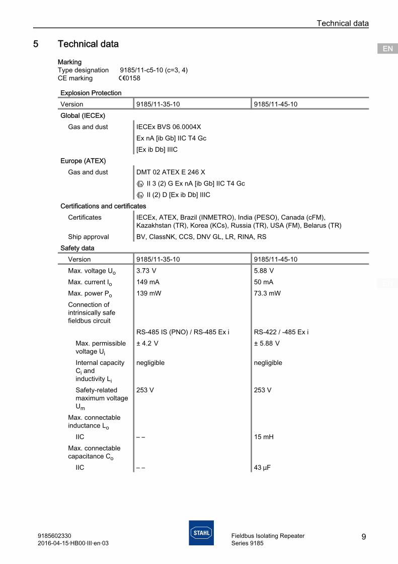
MarkingType designation 9185/11-c5-10 (c=3, 4)CE marking C0158
Explosion ProtectionVersion 9185/11-35-10 9185/11-45-10Global (IECEx)
Gas and dust IECEx BVS 06.0004XEx nA [ib Gb] IIC T4 Gc[Ex ib Db] IIIC
Europe (ATEX)Gas and dust DMT 02 ATEX E 246 X
E II 3 (2) G Ex nA [ib Gb] IIC T4 GcE II (2) D [Ex ib Db] IIIC
Certifications and certificatesCertificates IECEx, ATEX, Brazil (INMETRO), India (PESO), Canada (cFM),
Kazakhstan (TR), Korea (KCs), Russia (TR), USA (FM), Belarus (TR)Ship approval BV, ClassNK, CCS, DNV GL, LR, RINA, RS
Safety dataVersion 9185/11-35-10 9185/11-45-10Max. voltage Uo 3.73 V 5.88 V Max. current Io 149 mA 50 mAMax. power Po 139 mW 73.3 mWConnection of intrinsically safe fieldbus circuit
RS-485 IS (PNO) / RS-485 Ex i RS-422 / -485 Ex iMax. permissible voltage Ui
± 4.2 V ± 5.88 V
Internal capacity Ci and inductivity Li
negligible negligible
Safety-related maximum voltage Um
253 V 253 V
Max. connectable inductance Lo
IIC – – 15 mHMax. connectable capacitance Co
IIC – – 43 mF
91856023302016-04-15·HB00·III·en·03
9Fieldbus Isolating RepeaterSeries 9185

Technical dataENENENENENENENENENENENENENENENENENENENENENENENENEN
Technical DataElectrical data
Auxiliary powerNominal voltage UN
24 V UC
DC voltage range 18 ... 31.2 VAC voltage range 24 V ± 15 %Residual ripple within DC voltage range
( 3.6 VSS
Nominal current (24 V)
66 mA
Power input 1.6 WField side interface (X3)
Version RS-485 IS intrinsically safe, RS-422/RS-485Level setting: RS-485 IS (PNO specification) and RS-485 Ex i
(R. STAHL specification)Connections Sub-D socket X3, 9-poleTransmission rate 1.2 kBit/s ... 1.5 MBit/sSettings fixed transmission speed or automatic detection > 9.6 kBit/s
(only with Profibus DP)Conductor length depends on transmission rate and cableTerminating resistor
to be set in external plug
Data transmission indication
LED green "RxD3"
Safe area interface (X1)
Version RS-232 CConnection Sub-D plug X1, 9-poleLevel EIA RS-232 CTransmission rate 1.2 ... 93.75 kBit/sSettings fixed transmission speed or automatic detection > 9.6 kBit/s
(only with Profibus DP)Conductor length ( 20 mData reception indication
"RxD1" LED, green
10 91856023302016-04-15·HB00·III·en·03
Fieldbus Isolating RepeaterSeries 9185

Technical data ENENENENENENENENENENENENENENENENENENENENENENENENEN
Safe area interface (X2)
Version RS-485/RS-422Connection Sub-D plug X2, 9-poleLevel EIA RS-485, EIA RS-422Transmission rate 1.2 kBit/s ... 1.5 MBit/sSettings Keying RS-422 transmitter on/offConductor length depends on transmission rate and cableTerminating resistor
to be connected in external plug
Data reception indication
"RxD2" LED, green
Mounting / InstallationConnection diagram
Technical Data
for types9185/11-35-10.
09816E02
for types9185/11-45-10.
18110E00
Hazardous area Safe area
X3 485 ISRS8365
A-B+ISP (+)ISGND
X2 485RS8365
A-B+U+GND
9 1
7+
1 9
1
9- -
+24V UC
9 94 -
-
422RSA-B+
B+A-
TxD
RxD
X1 232RS235
RxDTxDGND
78
RTSCTS
GND
Division 1 Division 2
Zone 1 Zone 2
91856023302016-04-15·HB00·III·en·03
11Fieldbus Isolating RepeaterSeries 9185

Technical dataENENENENENENENENENENENENENENENENENENENENENENENENEN
MarkingType designation 9185/12-45-10CE marking C0158
Explosion ProtectionVersion 9185/12-45-10Global (IECEx)
Gas IECEx BVS 06.0004XEx nA IIC T4 Gc
Europe (ATEX)Gas BVS 10 ATEX E 105 X
E II 3 G Ex nA IIC T4 GcCertifications and certificates
Certificates IECEx, ATEX, Brazil (INMETRO), India (PESO), Canada (cFM), Kazakhstan (TR), Korea (KCs), Russia (TR), USA (FM), Belarus (TR)
Ship approval BV, ClassNK, CCS, DNV GL, LR, RINA, RS
Technical DataElectrical data
Auxiliary powerNominal voltage UN
24 V UC
DC voltage range 18 ... 31.2 VAC voltage range 24 V ± 15 %Residual ripple within DC voltage range
( 3.6 VSS
Nominal current (24 V)
66 mA
Power input 1.6 WOperation indication
LED green "PWR"
Undervoltage monitoring
yes
Field side interface (X3)
Version RS-485/RS-422Level EIA RS 485, EIA RS 422Connections Sub-D socket X3, 9-poleTransmission rate 1.2 kBit/s ... 1.5 MBit/sSettings fixed transmission speed or automatic detection > 9.6 kBit/s
(only with Profibus DP)Conductor length depends on transmission rate and cableTerminating resistor
to be set in external plug
Data transmission indication
LED green "RxD3"
12 91856023302016-04-15·HB00·III·en·03
Fieldbus Isolating RepeaterSeries 9185

Technical data ENENENENENENENENENENENENENENENENENENENENENENENENEN
System side interface (X1)
Version RS-232 CConnection Sub-D plug X1, 9-poleLevel EIA RS-232 CTransmission rate 1.2 ... 93.75 kBit/sSettings fixed transmission speed or automatic detection > 9.6 kBit/s
(only with Profibus DP)Conductor length ( 20 mTerminating resistor
– –
Data reception indication
"RxD1" LED, green
System side interface (X2)
Version RS-485/RS-422(switchable)
Connection Sub-D plug X2, 9-poleLevel EIA RS-485, EIA RS-422Transmission rate 1.2 kBit/s ... 1.5 MBit/sSettings Keying RS-422 transmitter on/offConductor length depends on transmission rate and cableEOL resistor to be connected in external plugData reception indication
"RxD2" LED, green
Mounting / InstallationConnection diagram
Technical Data
for types9185/12-45-10
18111E00
91856023302016-04-15·HB00·III·en·03
13Fieldbus Isolating RepeaterSeries 9185

EngineeringENENENENENENENENENENENENENENENENENENENENENENENENEN
For further technical data, see www.stahl-ex.com.
6 Engineering
7 Transport and storage• Transport and store the device only in the original packaging.• Store the device in a dry place (no condensation) and vibration-free.• Do not drop the device.• Comply with storage and transport temperatures.
Technical DataAmbient conditions
Ambient temperatureSingle device -20 ... +70 °CGroup assembly -20 ... +60 °C
The installation conditions affect the ambient temperature.Storage temperature -40 ... +80 °C Relative humidity (no condensation)
( 95 %
Use at the height of < 2000 m Mechanical data
Connection
NOTEDevice failure due to high ambient temperature.Non-compliance can result in damage to the device.
• Make sure that operation of the device is possible within the permissible temperature range.
Screw terminals Spring clamp terminalsSingle-wire connection- rigid- flexible- flexible with core end sleeves (without / with plastic sleeve)
0.2 ... 2.5 mm2
0.2 ... 2.5 mm2
0.25 ... 2.5 mm2
0.2 ... 2.5 mm2
0.2 ... 2.5 mm2
0.25 ... 2.5 mm2
two-wire connection- rigid- flexible- flexible with core end sleeves
0.2 ... 1 mm2
0.2 ... 1.5 mm2
0.25 ... 1 mm2
–
–
0.5 ... 1 mm2
14 91856023302016-04-15·HB00·III·en·03
Fieldbus Isolating RepeaterSeries 9185

Mounting and installation ENENENENENENENENENENENENENENENENENENENENENENENENEN
8 Mounting and installationThe device is approved for use in gas explosion hazardous areas of Zone 2 and dust explosion hazardous area of Zone 22 and in safe areas.
8.1 Dimensions / fastening dimensions
DANGERExplosion hazard due to installation without approved field enclosure!Non-compliance results in severe or fatal injuries!
• In hazardous areas Zone 2 or 22, the device must be installed in an enclosure which fulfils the requirements of IEC/EN 60079-15 or IEC/EN 60079-31.
DANGERExplosion hazard due to incorrect installation of the device! Non-compliance results in severe or fatal injuries.
• Carry out installation strictly according to the instructions and national safety and accident prevention regulations to maintain the explosion protection.
• Select and install the electrical device so that explosion protection is not affected due to external influences, i.e. pressure conditions, chemical, mechanical, thermal and electric impact such as vibration, humidity and corrosion (see IEC/EN 60079-14).
• The device must only be installed by trained qualified personnel who is familiar with the relevant standards.
Dimensional Drawing (All Dimensions in mm / inches) – Subject to Alterations
09820E00
X
99 mm / 3.90 "35,2 mm / 1.39 "
122 m
m / 4
.80 "
114,5
mm
/ 4
.51 "
Dimension XScrew terminals 108 mm / 4.25 inSpring cage terminals
118 mm / 4.66 in
91856023302016-04-15·HB00·III·en·03
15Fieldbus Isolating RepeaterSeries 9185

Mounting and installationENENENENENENENENENENENENENENENENENENENENENENENENEN
8.2 Mounting / dismounting, operating position
8.2.1 Mounting / dismounting on top hat railMounting
Dismounting
8.2.2 Mounting / dismounting pluggable terminalsAll devices are equipped with pluggable terminals.
Mounting• Plug the terminal into the device until the terminal engages.
Dismounting
8.3 Installation
15764E00
• Position the device on the top hat rail. Position the cut-out of the enclosure on the outside edge of the top hat rail.
• Engage the device on the top hat rail.• When swivelling the device onto the top hat rail,
make sure that it is not set at an angle.
15766E00
• Pull out the base bolt slightly using a screwdriver.• Swivel out the device.
10859E00
• Position the screwdriver behind the terminal.• Push out the terminal.
Operation under difficult conditions, such as, in particular, on ships, requires additional measures to be taken for correct installation, depending on the place of use. Further information and instructions on this can be obtained from your regional sales contact on request.
16 91856023302016-04-15·HB00·III·en·03
Fieldbus Isolating RepeaterSeries 9185

Mounting and installation ENENENENENENENENENENENENENENENENENENENENENENENENEN
8.3.1 Electrical connections• Follow the information provided in the section on "Technical Data".• The conductor must be connected carefully.• The conductor insulation must reach the clamping units.• Do not damage the conductor (nicking) when stripping it.• Ensure that the maximum permissible conductor temperatures and the maximum
permissible surface temperature are not exceeded by selecting suitable electric lines and means of running them.
• Avoid mechanical damage to the conductor insulation due to rubbing against sharp-edged or moving metal parts.
• Make sure that the correct tightening torque is used (0.5 to 0.6 Nm).
8.3.2 Schematic diagram
X1: Service and programming interfaceEx i = Intrinsically safe interface
Type 9185/11-c5-10, c=3,4 Type 9185/12-45-10
09816E00
15725E00
9185/11-35-10 9185/11-45-10 9185/12-45-10InterfaceDivision 1 and Zone 1, 21Safe area
xx
xx x
Field-side interfaceX3 RS-485 IS RS-485 Ex i
RS-422 Ex iRS-485RS-422
Safe area interfaceX1X2
RS-232RS-485RS-422
RS-232RS-485RS-422
RS-232RS-485RS-422
Hazardous area Safe area
X3 485 ISRS8365
A-B+ISP (+)ISGND
X2 485RS8365
A-B+U+GND
9 1
7+
1 9
1
9- -
+24V UC
9 94 -
-
422RSA-B+
B+A-
TxD
RxD
X1 232RS235
RxDTxDGND
78
RTSCTS
GND
Division 1 Division 2
Zone 1 Zone 2
Safe area
GND
X1 232RS235
RxDTxDGND
78
RTSCTS
X28365
A-B+U+GND
94 -
-
485RS
99
X3 422RS8394
A-B+A-B+
1
9
9-
7+24V UC
-
+
1
TxD
RxD
1
Division 2
Zone 2
91856023302016-04-15·HB00·III·en·03
17Fieldbus Isolating RepeaterSeries 9185

Mounting and installationENENENENENENENENENENENENENENENENENENENENENENENENEN
8.3.3 Compatibility at the PROFIBUS DP Ex i (9185/11-35-10)
When engineering a PROFIBUS DP Ex i segment, the specification according to which the segment will be structured must be defined (see the section on "Operation of devices at PROFIBUS DP Ex i").A DIP switch can be used to adapt the fieldbus isolating repeater 9185/11-35-10 to both bus specifications.
8.3.4 Compatibility at the PROFIBUS RS-485 IS (PNO) and RS-485 Ex i (STAHL) (9185/11-35-10)Operation of devices at the PROFIBUS DP Ex i (plug X3, RS-485 IS)
Components of PROFIBUS DP Ex i bus topology according to the specification of R. STAHL and components according to "PROFIBUS RS-485 IS" of PNO specification cannot be combined in a bus segment because of their different functional characteristics.
according to "PROFIBUS RS-485 IS" (PNO specification)
according to "R. STAHL specification"
Only devices according to "PROFIBUS RS-485 IS" specification may be connected to a bus segment.
Only devices according to "R. STAHL specification" may be connected to a bus segment.
Combination with devices according to "R. STAHL specification" is not permissible.
Combination with devices according to "PROFIBUS RS-485 IS" (PNO specification) is not permissible.
Switchable devices such as the fieldbus isolating repeater 9185/11-35-10 must be adapted to the DP bus topology according to "PROFIBUS RS-485 IS".
Switchable devices such as the fieldbus isolating repeater 9185/11-35-10 must be adapted to the DP bus topology according to "R. STAHL specification".
Bus termination according to "PROFIBUS RS-485 IS" specification, for example,
• with Sub-D PROFIBUS plug order number: 201805 (angled)
• with Sub-D PROFIBUS plug order number: 162693
For bus termination according to "R. STAHL specification", see the "Engineering, Installation and Commissioning of the RS-485 Fieldbus System from R. STAHL for Safe and Hazardous Areas" manual, for example,
• with R. STAHL PROFIBUS plug order number: 162699
Non-Ex PROFIBUS plugs must not be used in the Ex i segment.Ex PROFIBUS plugs must not be used in non-Ex segments.
18 91856023302016-04-15·HB00·III·en·03
Fieldbus Isolating RepeaterSeries 9185

Mounting and installation ENENENENENENENENENENENENENENENENENENENENENENENENEN
Bus connection to devices with PROFIBUS plug connectors from R. STAHL
Plug for X3 (RS-485 IS or RS-485 Exi)
DeviceBus topology according toRS-485 IS PNO RS-485 Ex i
(R. STAHL specification)Fieldbus isolating repeater Interface X3
162693 (straight)201805 (angled)
162699
CPM 9440/12-.... (24V Z1) -CPM 9440/22-.... (230V Z1) 162693 (straight)
Combination of several PROFIBUS segments with different specifications in one PROFIBUS network is permissible.
RS-485 IS PNO RS-485 Ex i(R. STAHL specification)
Termination Both bus ends of a segment actively terminated with 200 Ω
Ex i segment terminated with 120 Ω active EOL resistor.
Plug 162693 (straight) or 201805 (angled) 162699Wiring R = 200 Ω R = 120 Ω
08998E00
91856023302016-04-15·HB00·III·en·03
19Fieldbus Isolating RepeaterSeries 9185

Parameterization and commissioningENENENENENENENENENENENENENENENENENENENENENENENENEN
8.3.5 Connection and plug assignment overview
9 Parameterization and commissioningBefore commissioning, ensure the following:• Installation of the device according to regulations.• Correct connection of the cables.• No damage at the device and connection cables.• Tight seat of the screws at the terminals. Correct tightening torque: 0.5 ... 0.6 Nm.
Fieldbus isolating repeater 9185/11-35-10 Fieldbus isolating repeater 9185/1.-45-10
Connection (pin)
Designation Connection (pin)
Designation
X1: RS-232 (system side) X1: RS-232 (system side)
23578
RxDTxDGNDRTSCTS
23578
RxDTxDGNDRTSCTS
X2: RS-485 (system side)
RS-422 (system side)
X2: RS-485 (system side)
RS-422 (system side)
836594
A-B+U+GND––
A- (TxD)B+ (TxD)––A- (RxD)B+ (RxD)
836594
A-B+U+GND––
A- (TxD)B+ (TxD)––A- (RxD)B+ (RxD)
X3: RS-485 (field side)
X3: RS-485 (field side)
RS-422 (field side)
8365
A-B+ISP+IS GND
83659472
A-B+U+GND––––
A- (TxD)B+ (TxD)U+GNDA- (RxD)B+ (RxD)U+GND
Auxiliary power Auxiliary power7 8 9
U+ (24 V UC)PAU- (0 V)
7 8 9
U+ (24 V UC)PAU- (0 V)
Changing the switch settings is also permitted during operation in Zone 2 and with connected intrinsically safe input signals.
20 91856023302016-04-15·HB00·III·en·03
Fieldbus Isolating RepeaterSeries 9185

Parameterization and commissioning ENENENENENENENENENENENENENENENENENENENENENENENENEN
9.1 Replacement of the device• If replacing by a device with identical design, readjust the DIP switch, if necessary.
9.2 Overview of functions
*) Bit retiming only from 93.75 kBit
9.3 DIP switch settings 9185/11-35-10
Incorrect parameterization or an incorrect update can result in the device not working properly.
• Please carry out parameterization carefully and exactly as per the instructions.
Type Field side (X3) RS2 switch Auto baud rate detection
Bit retiming *) Full duplex
9185/11-35-10 RS-485 IS any Yes (PROFIBUS)
Yes No
9185/11-45-10 RS-485 Ex i OFF Yes (PROFIBUS)
Yes No
RS-422 Ex i ON No No Yes9185/12-45-10 RS-485 OFF Yes
(PROFIBUS)Yes No
RS-422 ON No No Yes
System-side interface (X2)RS-485 *) RS-422
08789E00 08720E00
RS-422 transmitter(If RS2 = OFF)
RS-422 transmitter(If RS2 = ON)
switched off *) direction permanently on spring return
08995E00 08993E00 08997E00 08973E00
91856023302016-04-15·HB00·III·en·03
21Fieldbus Isolating RepeaterSeries 9185

Parameterization and commissioningENENENENENENENENENENENENENENENENENENENENENENENENEN
*) = Default setting
9.4 DIP switch settings 9185/11-45-10
*) = Default setting
Field-side transmission level(X3)R. STAHL PNO *)
08719E00 08713E00
System-side interface (non-Ex i (X2))RS-485 RS-422 *)
08803E00 08751E00
RS-422 transmitter(If RS2 = OFF)
RS-422 transmitter(If RS2 = ON)
switched off *) direction permanently on spring return
09000E00 08994E00 08996E00 08999E00
Field-side interface Ex i(X3)RS-485 RS-422 *)
08992E00 08991E00
22 91856023302016-04-15·HB00·III·en·03
Fieldbus Isolating RepeaterSeries 9185

Parameterization and commissioning ENENENENENENENENENENENENENENENENENENENENENENENENEN
9.5 DIP switch settings 9185/12-45-10
*) = Default setting
9.6 "BAUD" decode switch for setting the transmission speedIn the fieldbus isolating repeater, the speed (baud rate) of data transfer between the fieldbus isolating repeater itself and the operating device is set using the decode switch. The corresponding possible settings are shown in the following table.
*) Default setting upon delivery**) 9185/11-35-10: AutoDetect (PROFIBUS DP only)9185/1.-45-10: AutoDetect at RS2 = OFF (PROFIBUS DP only) / 57.6 kBits/s at RS2 = ON
System-side interface (X2)RS-485 *) RS-422
08803E00 08751E00
RS-422 transmitter(If RS2 = OFF)
RS-422 transmitter(If RS2 = ON)
switched off *) direction permanently on spring return
09000E00 08994E00 08996E00 08999E00
Field-side interface(X3)RS-485 *) RS-422
08992E00 08991E00
0 *) 1 2 3 4 5 6 7Bit/s Auto **) 1.2 k 2.4 k 4.8 k 9.6 k 19.2 k 38.4 k 45.45 kConductor length
( 1200 m ( 1200 m ( 1200 m ( 1200 m ( 1200 m ( 1200 m ( 1200 m
8 9 A B C D E FBit/s 57.6 k 93.75 k 187.5 k 375 k 500 k 1 M 1.5 M ReservedConductor length
( 1200 m ( 1200 m ( 1000 m ( 400 m ( 400 m ( 200 m ( 200 m
91856023302016-04-15·HB00·III·en·03
23Fieldbus Isolating RepeaterSeries 9185
OperationENENENENENENENENENENENENENENENENENENENENENENENENEN
10 Operation
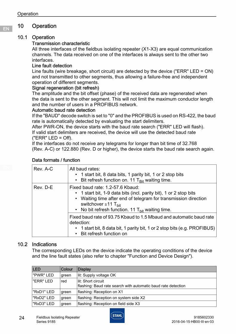
10.1 OperationTransmission characteristicAll three interfaces of the fieldbus isolating repeater (X1-X3) are equal communication channels. The data received on one of the interfaces is always sent to the other two interfaces.Line fault detectionLine faults (wire breakage, short circuit) are detected by the device ("ERR" LED = ON) and not transmitted to other segments, thus allowing a failure-free and independent operation of different segments.Signal regeneration (bit refresh)The amplitude and the bit offset (phase) of the received data are regenerated when the data is sent to the other segment. This will not limit the maximum conductor length and the number of users in a PROFIBUS network.Automatic baud rate detectionIf the "BAUD" decode switch is set to "0" and the PROFIBUS is used on RS-422, the baud rate is automatically detected by evaluating the start delimiters.After PWR-ON, the device starts with the baud rate search ("ERR" LED will flash). If valid start delimiters are received, the device will use the detected baud rate ("ERR" LED = Off). If the interfaces do not receive any telegrams for longer than bit time of 32.768 (Rev. A-C) or 122.880 (Rev. D or higher), the device starts the baud rate search again.
Data formats / function
10.2 IndicationsThe corresponding LEDs on the device indicate the operating conditions of the device and the line fault states (also refer to chapter "Function and Device Design").
Rev. A-C All baud rates:• 1 start bit, 8 data bits, 1 parity bit, 1 or 2 stop bits • Bit refresh function on. 11 TBit waiting time.
Rev. D-E Fixed baud rate: 1.2-57.6 Kbaud:• 1 start bit, 1-9 data bits (incl. parity bit), 1 or 2 stop bits• Waiting time after end of telegram for transmission direction
switchover )11 Tbit• No bit refresh function. 11 Tbit waiting time.
Fixed baud rate of 93.75 Kbaud to 1.5 Mbaud and automatic baud rate detection:
• 1 start bit, 8 data bit, 1 parity bit, 1 or 2 stop bits (e.g. PROFIBUS)• Bit refresh function on
LED Colour Display"PWR" LED green lit: Supply voltage OK"ERR" LED red lit: Short circuit
flashing: Baud rate search with automatic baud rate detection"RxD1" LED green flashing: Reception on X1"RxD2" LED green flashing: Reception on system side X2"RxD3" LED green flashing: Reception on field side X3
24 91856023302016-04-15·HB00·III·en·03
Fieldbus Isolating RepeaterSeries 9185

Maintenance and repair ENENENENENENENENENENENENENENENENENENENENENENENENEN
91856023302016-04-15·HB00·III·en·03
25Fieldbus Isolating RepeaterSeries 9185
10.3 TroubleshootingObserve the following troubleshooting plan for troubleshooting:
If the error cannot be eliminated using the mentioned procedures:• Contact R. STAHL Schaltgeräte GmbH.For fast processing, have the following information ready: • Type and serial number of the device• Purchase information • Error description • Intended use (in particular input / output wiring)
11 Maintenance and repair
11.1 Maintenance• Consult the relevant national regulations to determine the type and extent
of inspections.• Adapt inspection intervals to the operating conditions.
During maintenance of the device, check at least:• whether the clamping screws holding the electric lines are securely seated,• whether the device enclosure and / or protective enclosure have cracks or other visible
signs of damage, • whether the permissible ambient temperatures are observed,• whether the device is used according to its designated use.
Error Cause of error Troubleshooting"PWR" LED is off • Auxiliary power failure
• Defective device fuse
• Polarity reversal of the auxiliary power source
• Check the polarity of the auxiliary power source.
• Check the wiring of the auxiliary power source.
• If the fuse is defective, have the device repaired.
"ERR" LED is lit Short circuit Check the connection cable and plug."ERR" LED is flashing No telegrams are being
received by the system• Check the system.• Check the cables.• For non-PROFIBUS DP
protocols: Set the baud rate manually at the "BAUD" rotary switch.
No communication • Bus not active• Wrong plug used with pas-
sive EOL resistor
• Start bus.• Use a plug with active EOL
resistor.

CleaningENENENENENENENENENENENENENENENENENENENENENENENENEN
11.2 MaintenanceThe device does not require regular maintenance.
11.3 Repair
11.4 Returning the deviceUse the "Service form" to return the device if repair or service is required. On the internet site "www.stahl-ex.com" under "Downloads > Customer service":• Download the service form.• Fill out the service form.• Send the device along with the service form in the original packaging to
R. STAHL Schaltgeräte GmbH.
12 Cleaning• To avoid electrostatic charging, the devices located in potentially explosive areas may
only be cleaned using a damp cloth.• When cleaning with a damp cloth, use water or mild, non-abrasive, non-scratching
cleaning agents.• Do not use aggressive detergents or solvents.
13 Disposal• Observe national and local regulations and statutory regulation regarding disposal.• Separate materials when sending it for recycling.• Ensure environmentally friendly disposal of all components according to the statutory
regulations.
14 Accessories and Spare parts
Observe the relevant national regulations in the country of use.
DANGERExplosion hazard due to improper repair!Non-compliance results in severe or fatal injuries.
• Repair work on the devices must be performed only by R. STAHL Schaltgeräte GmbH.
NOTEMalfunction or damage to the device due to the use of non-original components.Non-compliance can result in material damage.
• Use only original accessories and spare parts from R. STAHL Schaltgeräte GmbH.
For accessories and spare parts, see data sheet on our homepage www.stahl-ex.com.
26 91856023302016-04-15·HB00·III·en·03
Fieldbus Isolating RepeaterSeries 9185