Installation suggestion FOUNDATION Fieldbus - ABB · PDF fileData Sheet 10/63-0.50 EN Rev. A...
12
Data Sheet 10/63-0.50 EN Rev. A Installation suggestion FOUNDATION Fieldbus F Operate Engineer Control Field FOUNDATION Fieldbus-HSE Ethernet Linking Device FOUNDATION Fieldbus-H1 FOUNDATION Fieldbus-H1 FOUNDATION Fieldbus-HSE/H1 — LD 800HSE Linking Device FOUNDATION Fieldbus-H1 — FieldBarrier in Ex (Haz.) area — Passive T and 4-way-junction in Non-Ex area Shielding and grounding — FOUNDATION Fieldbus-H1 FOUNDATION Fieldbus-H1 layout example — FieldBarrier in Ex (Haz.) area — Passive 4-way junction in Non-Ex area
-
Upload
nguyentuong -
Category
Documents
-
view
227 -
download
1
Transcript of Installation suggestion FOUNDATION Fieldbus - ABB · PDF fileData Sheet 10/63-0.50 EN Rev. A...

Data Sheet 10/63-0.50 EN Rev. A
Installation suggestion FOUNDATION Fieldbus
F
Operate
Engineer
Control
Field
FOUNDATION Fieldbus-HSE
Ethernet
LinkingDevice
FO
UN
DA
TIO
NF
ield
bu
s-H
1
FO
UN
DA
TIO
NF
ield
bu
s-H
1
FOUNDATION Fieldbus-HSE/H1 — LD 800HSE Linking Device FOUNDATION Fieldbus-H1 — FieldBarrier in Ex (Haz.) area — Passive T and 4-way-junction in Non-Ex area Shielding and grounding — FOUNDATION Fieldbus-H1 FOUNDATION Fieldbus-H1 layout example — FieldBarrier in Ex (Haz.) area — Passive 4-way junction in Non-Ex area

FOUNDATION Fieldbus - Installation suggestion
2 Draft3_10/63-0.50 DE
FOUNDATIONFieldbus-HSE
InterfaceController
Ethernet TCP/IP
Operate Engineer
Control
Engineer /Asset Management
US
Field
Field
Switch
FO
UN
DAT
ION
Fie
ldbu
s-H
1F
OU
ND
ATIO
NF
ield
bus-
H1
FOUNDATION Fieldbus-H1
1)
1)1) FOUNDATION
Fieldbus-HSE
Asset Vision
FO
UN
DAT
ION
Fie
ldbu
s-H
1
T
U
FO
UN
DAT
ION
Fie
ldbu
s-H
1
See page 4
See page 7 See page 8
See page 6
Non-Ex area
Ex (Haz.) area zone 1
M00559_EN
Overview
Refer to “Fieldbus FOUNDATION AG-140 Technical Guides: Wiring and Installation“ http://www.fieldbus.org
ABB offers a wide range of IP 65 ... IP 68 FOUNDATION Fieldbus-H1 devices for Non-Ex and Ex (Haz.) areas, incl. FISCO approval. Optional cable bushing or 7/8” plugs at the housing for: Flowmeter, Temperature Transmitter, Pressure and Level Transmitter, Positioner, Analyzer, ...
See data sheet - 10/63-0.56

FOUNDATION Fieldbus - Installation suggestion
10/63-0.50 DE -Draft3 3
FOUNDATION Fieldbus-HSE/H1 - LD 800HSE Linking Device
Color coding:
FOUNDATION Fieldbus-H1:
H1+
H1-
= orange
= blue
Ethernet TCP/IPFOUNDATIONFieldbus-HSE Interface
Controller
Switch
1)
1) FOUNDATION Fieldbus-HSE
1) 1) Seepage 5
Seepage 4
M00560_EN
FOUNDATION Fieldbus-HSE/H1 - LD 800HSE (with Power Conditioner)
Description Catalog No. Data sheetLD 800HSE - Linking Device HSE/H1 3BDH000320R02 3BDD011675Rxx011
HSE-Bus 10 and 100 Mbit/s, 4 x H1-Bus fix 31.25 kBit/s, IP 20, rail mounting ♦ Power-PINs: L+ = (+), M = (-)
♦ PINs: FF1 / FF2 / FF3 / FF4: (+) = H1+, (-) = H1-, S = shielding
FOUNDATION Fieldbus-H1 cable, orange
63668-9 890 16x 10/63-6.67 2
NFC080-NO - 0.88 mm², 43.6 Ω/km, 65/330/1000 m
KLD2-PC-1.1.IEC - Power Conditioner On request 3
H1-power supply: US = 14.7 ... 30.7 V DC, IS ≤ 1 A, incl. switchable bus termination. ♦ Power-PINs: 8 = (+), 9 = (-)
♦ H1-PINs: IN: 6 = H1+, 5 = H1-, 4 = shielding
OUT: 3 = H1+, 2 = H1-, 1 = shielding
+
-
+
-
24
V D
C200 m
A≤
L+
M
04 05 06
BA
07 08 09
C
+
-
+
-
1
2
3
03 02 01
Ex (Haz.) areaNon-Ex area
Seepage 6
Seepage 7/8
Or
16 … 32 V DC1.02 A≤
M00561_EN
Attention (valid for all pages): For the PIN coding the respective product data sheet is relevant!

FOUNDATION Fieldbus - Installation suggestion
4 10/63-0.50 DE
FOUNDATION Fieldbus-HSE/H1 - LD 800HSE Linking Device (with Motherboard, Simplex) Description Catalog No. Data sheet
LD 800HSE - Linking Device HSE/H1 3BDH000320R02 3BDD011675Rxx011
HSE-Bus 10 and 100 Mbit/s, 4 x H1-Bus fix 31.25 kBit/s, IP 20, rail mounting ♦ Power-PINs: L+ = (+), M = (-)
♦ PINs: FF1 / FF2 / FF3 / FF4: (+) = H1+, (-) = H1-, S = shielding
FOUNDATION Fieldbus-H1 cable, orange 63668-9 890 16x 10/63-6.67 2
NFC080-NO - 0.88 mm², 43.6 Ω/km, 65/330/1000 m
MB-FB-4 On request 3
Motherboard, for 4x power supply modules & for 1x diagnostic module, 4x switchable H1 bus terminator, DIN top-hat rail, IP 20, II 3G EEx nAC IIC T4, Zone 2/Class I, Div. 2. ♦ Power PINs: PRI: + = (+), - = GND, SEC (optional): + = (+), - = GND
♦ H1 PINs: IN segment 1/2/3/4: + = H1+, - = H1-, S =shield
♦ H1 PINs: OUT segment 1:+ = H1+, - = H1-, ACC-MB-HSK = shield and! motherboard grounding firmly.
OUT segment 2/3/4: + = H1+, - = H1-, ACC-MB-HSK = shield
ACC-MB-HSK (optional) On request 4
Grounding connection set for large-surface connection of the trunk cable shields.
Power supply modules On request 5
H1 bus fixed at 31.25 kbit/s, IP 20, II 3G EEx nA II T4, Zone 2/Class I, Div. 2.
HD2-FBPS-1.500 (for "A", "B", or "C")
- H1 power feed: US = 28 ... 30 V DC, IS ≤ 500 mA, elec. isolation.
HD2-FBCL-1.500 (for "A", "B", or "C")
- H1 power feed: US = 16.7 ... 29.5 V DC, IS ≤ 500 mA, no elec. isolation.
Diagnostic modules (optional) On request
SEGSEG SEGSEG
+
-
+
-
+
-
+
-
24V
DC
200
mA
≤
L+
M
+ S -+ S - - + - +
Opt
iona
l
S - +
+ S -+ S -
S - +
+ S -+ S -
S - +
+ S -+ S -
S - +
FOUNDATIONFieldbus-H1
A
+ - S
A
+ - S
B
+ - S
C
+ - S
1
2
3
5
6
4
19.2 ... 35 V DC16 A≤
≤(typ. 4.03 A)
Seepage 3
Non-Ex areaEx (Haz.) area
Seepage 6
Or Seepage 7/8
M00562_EN
6
For supply & H1 bus, IP 20, Zone 2/Class I, Div. 2.
HD2-DM-B (Basic), II 3G EEx nAC IIC T4
- Check power sources, power supply modules,
and H1 for overload and short circuit, etc.
- Messages only transmitted by means of relay contact.
HD2-DM-A (Advanced), II 3G EEx nA IIC T4
- Additional physical layer checks.
- DTM Diagnostic Manager (one of three is required)
- DTM Basic version
- DTM-FC.AD Professional, ≤ 100 segments
- DTM-FC.AD.1 Professional, > 100 segments
Important! (For Simplex only)
Color coding: FOUNDATION Fieldbus-H1:
- Max. 31 H1 field devices per power supply module.
- All modules can be combined with all other modules.
- First check that the diagnostic DTMs have been approved for your frame application.
H1+
H1-
= orange
= blue

FOUNDATION Fieldbus - Installation suggestion
10/63-0.50 DE -Draft3 5
FOUNDATION Fieldbus-HSE/H1 - LD 800HSE Linking Device (with Motherboard, Redundant)
Color coding:
FOUNDATION Fieldbus-H1:
SEG 1
+ - S
SEG 1
+ - S
SEG 1
+ - S
SEG 1
+ - S
5
4
6
7
A A B C
Optio
nal
1
+
-
+
-
24
V D
C200 m
A≤
L+
M
+
-
+
-
+
-
+
-
+
-
+
-
S - +S - +S - +S - +S - +S - +S - + S - +
- +- +
1
2
3
Seepage 3
19.2 ... 35 V DC16 A≤
≤(typ. 7.95 A)
Non-Ex areaEx (Haz.) area
Seepage 6
Seepage 7 / 8 M00563_EN
Or
H1+
H1-
= orange
= blue
Description Catalog No. Data sheet
LD 800HSE - Linking Device HSE/H1 3BDH000320R02 3BDD011675Rxx01
Important!
1
HSE bus with 10 and 100 Mbit/s, 4 x H1 buses fixed at 31.25 kbit/s, IP 20, top-hat rail mounting ♦ Power PINs: L+ = (+), M = (-)
♦ PINs: FF1 / FF2 / FF3 / FF4: (+) = H1+, (-) = H1-, S = shield
2 Redundancy Link Cable, 0.50 m 3BDH000281R1 3BDD011675Rxx01
FOUNDATION Fieldbus-H1 cable, orange 63668-9 890 16x 10/63-6.67 3
NFC080-NO - 0.88 mm², 43.6 Ω/km, 65/330/1000 m
MB-FB-4R On request 4
Motherboard, for 2x4 power supply modules (redundant) & for 1x diagnostic module, 2x4 host connections (redundant), 4x switchable H1 bus terminator, DIN top-hat rail, IP 20, II 3G EEx nAC IIC T4, Zone 2/Class I, Div. 2. ♦ Power PINs: PRI: + = (+), - = GND, SEC (optional): + = (+), - = GND
♦ H1 PINs: IN A/B segment 1/2/3/4: + = H1+, - = H1-, S = shield
♦ H1 PINs: OUT segment 1: + = H1+, - = H1-, ACC-MB-HSK = shield and! motherboard grounding firmly.
OUT segment 2/3/4: + = H1+, - = H1-, ACC-MB-HSK = shield
5 ACC-MB-HSK (optional) On request
Power supply modules On request 6
HD2-FBPS-1.500 (for "A", "B", or "C")
HD2-FBCL-1.500 (for "A", "B", or "C")
Diagnostic modules (optional) On request
- Max. 30 H1 field devices per power supply module (red.).
- All modules can be combined with all other modules.
- If only one LD 800HSE (host) is being used, the redundancy switch must be switched to the motherboard.
- First check that the diagnostic DTMs have been approved for your frame application.
7
HD2-DM-B (Basic)
HD2-DM-A (Advanced)
- DTM Diagnostic Manager (one of three is required)

FOUNDATION Fieldbus - Installation suggestion
6 10/63-0.50 DE
FOUNDATION Fieldbus-H1 – FieldBarrier in Ex (Haz.) area Description Catalog No. Data sheet
H1 overvoltage protection, 2-channel, IN ≤ 450 mA (Optional) NGV211-NO - Cartridge for NGV210-NO
NGV210-NO - Basic element for top-hat rail
63615-9 890 181
63615-9 890 180
10/63-6.15
10/63-6.15
1
♦ PINs:
1. channel: IN: 01 = H1+, 05 = H1-, 03 = shielding OUT: 02 = H1+, 06 = H1-, 04 = shielding
2. channel: IN: 07 = H1+, 11 = H1-, 09 = shielding OUT: 08 = H1+, 12 = H1-, 10 = shielding
FOUNDATION Fieldbus-H1 cable, orange (No intrinsic safety) 2
NFC080-NO - 0.88 mm², 43.6 Ω/km, 65/330/1000 m
NFC150-NO1) - 1.30 mm², 27.4 Ω/km, 1000 m
NFC250-NO1) - 2.10 mm², 17.2 Ω/km, 1000 m
63668-9 890 16x
63668-9 890 169
63668-9 890 170
10/63-6.67
10/63-6.67
10/63-6.67
F2D0-FB-Ex4.CG - FieldBarrier On request 3
- IP 67, aluminium housing, II 2 (1G/D) G EEx me [ia] IIC T4
- 6x cable bushing plastic (shielding capacitive!), switchable bus termination. ♦ PINs: trunk cable (LT): IN:03 = H1+, 04 = H1-, 05 = S OUT: 08 = H1+, 07 = H1-, 06 = S
♦ PINs: spur cable (LS):4xOUT:10 = H1+, 11 = H1-, 12 = S / 13 = H1+, 14 = H1-, 15 = S
16 = H1+, 17 = H1-, 18 = S / 19 = H1+, 20 = H1-, 21 = S
RD0-FB-Ex4 - FieldBarrier, IP 20, On request rail mounting (Alternative, not shown)
4 6x EMC cable bushing Special order!
(Shielding braid on ground via cable bushing)
FOUNDATION Fieldbus-H1 cable, blue 63668-9 890 17x 10/63-6.67 5
(Intrinsic safety) NFC080-EX - 0.88 mm2, 43.6 Ω/km, 65/330/1000 m
6 NFE300-NE - H1 Kabelbuchse, IP 67 3KDE636640L0102 10/63-6.60
- Metal / plastic case, 7/8”, for Ex (Haz.) and Non-Ex area ♦ PINs: 1 = H1-, 2 = H1+, 3 = shielding
7 NGV220-EX2) - H1 overvoltage protection (optional) 63615-7 964 115 10/63-6.15
- IP 67 metal case, for M20 x 1.5 cable gland mounting, II2(1)G EEx ia IIC T4/T5/T6
♦ PIN: IN: (+) = H1+, (-) = H1-, shielding on ground via EMC cable bushing
♦ PINs OUT:red = H1+, black = H1-, shielding on ground via metal case
- Possible use at the FieldBarrier of the IN/OUT-PINs of the trunk cable (LT) by using EMC cable bushing (shielding capacity bridged).
8 FieldBarrier - Supply voltage per channel:
US 12.25 V (at 10 mA) up to 9.78 V (at 43 mA)
- Supply current per channel: IS ≤ 43 mA
- Basic current per FieldBarrier: Ibasic ≤ 49 mA
10 13 16 19 22 25 28 31 34 37 40 mA
43 mAV
13.0
12.5
12.0
11.5
11.0
10.5
10.0
9.5
9.0
FieldBarrierOutput characteristic per channel
Sup
ply
volta
ge U
S
Field device current IS
V12.25
9.78
M00538_EN
Operation area
Color coding:
FOUNDATION Fieldbus-H1: H1+ = orange H1- = blue
FO
UN
DAT
ION
Fie
ldbu
s-H
1
EEx e
EEx ia
LS
EEx ia
A
LS
LT
(Option)
aaaaaaaaaaaaaaaaaaaaaaaaaaaaaaaaaaaaaaaaaaaaaaaaaaaaaaaaaaaaaaaaaaaaaaaa
(Option)
02 04 06
IN
OUT
01 03 05
28 V DC!
EEx e
10 11 12 13 14 1516 17 1819 20 2103 04 0506 07 08
!
10 11 12 13 14 1516 17 1819 20 2103 04 0506 07 08
!
1
2
3
4
5
6
8
7
Seepage 3/4/5
Non-Ex area
Ex (Haz.) area zone 1/2
FF
-H1
“blu
e”
Field devices
FF
-H1
“blu
e”
Field devices
Bus termination eachat the beginning and theend of every H1 segmentnecessary!
M00564_EN
1) By using the 1.3 / 2.1 mm2 cable it is not possible to use plugs / sockets! 2) By using the Field device types FXE4000, FV4000, FS4000 it is not possible to use NGV220!
Limits and rules! When using the Power Hubs, FieldBarrier and ABB cable (by other Power Conditioner / Barriers / cable the limits are calculated new). per FOUNDATION Fieldbus-H1 segment: - number of H1 subscribers ≤ 16 - number of FieldBarrier ≤ 4 - Σ current (I) ≤ 450 mA (max. current via NGV21x-NO) Σ current (I) = Σ basic current of all Field devices and FieldBarriers
+ error current of one device - trunk cable length (LT) see diagram at US min. 16.0 V DC of FieldBarrier
(length depending on Σ current and cable diameter) - spur cable length (LS) (acc. to the FISCO/IEC 60079-27 model):
at 1 ... 12 spur cable: LS ≤ 120 m at 13 ... 14 spur cable: LS ≤ 90 m at 15 ... 16 spur cable: LS ≤ 60 m
- cable length Ltotal = LT+ (Σ LS) ≤ 1900 m
0
300
600
900
1200
1500
1800
0 50 100 150 200 250 300 350 400 450 mA
L /mT
At H1 power supply of &FieldBarrier U min. 16.0 V DC
28 V DC!S ABB cable
type A
2.10 mm2
1.30 mm2
0.88 mm2
M00565_EN

FOUNDATION Fieldbus - Installation suggestion
10/63-0.50 DE -Draft3 7
FOUNDATION Fieldbus-H1 – Passive T and 4-way junction (IP 66) in Non-Ex area Description Catalog No. Data sheet
H1 overvoltage protection, 2-channel, IN ≤ 450 mA (Optional)
NGV211-NO - Cartridge for NGV210-NO NGV210-NO - Basic element for top-hat rail
63615-9 890 181
63615-9 890 180
10/63-6.15
10/63-6.15
1
♦ PINs: 1. channel: IN: 01 = H1+, 05 = H1-, 03 = shielding OUT: 02 = H1-, 06 = H1-, 04 = shielding
2. channel: IN: 07 = H1+, 11 = H1-, 09 = shielding OUT: 08 = H1+, 12 = H1-, 10 = shielding
2 FOUNDATION Fieldbus-H1 cable, orange NFC080-NO - 0.88 mm2, 43.6 Ω/km,
65/330/1000 m NFC150-NO1) - 1.30 mm2, 27.4 Ω/km, 1000 m
63668-9 890 16x
63668-9 890 169
10/63-6.67
10/63-6.67
3 NFJ120-NE - H1 T-junction, IP 66 3KDE636630L0001 10/63-6.60
- 2x EMC cable bushing (Shielding braid on ground via cable bushing) ♦ PINs: trunk cable (LT): IN/OUT: A = H1-, B = H1+
NFE100-NE - H1 cable plug, IP 67 3KDE636640L0101 10/63-6.60 4 - Metal / plastic case, 7/8”, for Ex (Haz.) and Non-Ex area ♦ PINs: 1 = H1-, 2 = H1+, 3 = shielding
FOUNDATION Fieldbus-H1 cable, orange 63668-9 890 16x 10/63-6.67 5
NFC080-NO - 0.88 mm2, 43.6 Ω/km, 65/330/1000 m NGV220-NO2) - H1 overvoltage protection (optional)
63615-7 964 116 10/63-6.15 6
- IP 67 metal case, for M20 x 1.5 cable gland mounting ♦ PINs: IN: (+) = H1+, (-) = H1-, shielding on ground via EMC cable bushing
♦ PINs: OUT: red = H1+, black = H1-, shielding on ground via metal case
7 NPJ130-NO - H1 T-junction, IP 66 63643-9 890 102 10/63-6.60
- 3x EMC cable bushing, switchable bus termination (Shielding braid on ground via cable bushing)
♦ PINs: trunk cable (LT): IN/OUT: A = H1-, B = H1+
♦ PINs: spur cable (LS): OUT: A = H1-, B = H1+
NFE300-NE - H1 cable socket, IP 67 3KDE636640L0102 10/63-6.60 8 - metal / plastic case, 7/8”, for Ex (Haz.) and Non-Ex area ♦ PINs: 1 = H1-, 2 = H1+, 3 = shielding
9 NFJ420-NE - H1 4-way junction, IP 66 3KDE636630L0002 10/63-6.60
- 2x EMC cable bushing, (Shielding braid on ground via cable bushing)
♦ PINs: trunk cable (LT) IN/OUT: A = H1-, B = H1+
NPJ460-NO - H1 4-way junction, IP 66 63643-9 890 104 10/63-6.60
- 6x EMC cable bushing, switchable bus termination (Alternative, not shown)
10 NPZ100-EX - H1 bus termination For NFJx20-NE needed only, IP 66
63645-9 890 120 10/63-6.60
Color coding:
FOUNDATION Fieldbus-H1: H1+ = orange H1- = blue
M00567_EN
(Option)
LT
FO
UN
DA
TIO
NF
ield
bus-H
1
FF-H1
aaaaaaaaaaaaaaaaaaaaaaaaaaaaaaaaaaaaaaaaaaaaaaaaaaaaaaaaaaaaaaaaaaaaaaaa02 04 06
IN
OUT
01 03 05
B
(Option)
LS
A B
A B
AB
FF-H1
A B
A B
A B
A B
28 V DC!
1
2
3
7
6
9
8
4
5
10
Seepage 3/4/5
Fie
ld d
evic
es
Bus termination each at thebeginning and the end of everyH1 segment necessary!
1) By using the 1.3 mm2 cable it is not possible to use plugs / sockets! 2) By using the Field device types FXE4000, FV4000, FS4000 it is not possible to use NGV220!
Limits and rules! When using the Power Hubs and ABB junction & cable. (by other Power Conditioner / junction / cable the limits are calculated new) per FOUNDATION Fieldbus-H1 segment: - number of H1 subscribers ≤ 31 - Σ current (I) ≤ 450 mA (max. current via NGV21x-NO) Σ current (I) = Σ basic current of all field devices + error current of one device - trunk cable length (LT) of 0.88 mm2 cable see diagram
(length (LT) depending on Σ current, US field device and cable diameter)
- spur cable length (LS): at 1 ... 12 spur cable: LS ≤ 120 m / at 13 ... 14 spur cable: LS ≤ 90 m at 15 ... 18 spur cable: LS ≤ 60 m / at 19 ... 24 spur cable: LS ≤ 30 m at 25 ... 31 spur cable: LS ≤ 1 m
- cable length Ltotal = LT+ (Σ LS) ≤ 1900 m 0
300
600
900
1200
1500
1800
0 50 100 150 200 250 300 350 400 450 mA
L /mT
= 9 V DC= 10 V DC= 11 V DC= 12 V DC
= 16 V DC
At H1 power supply of &ABB cable type A = 0.88 mm
28 V DC!2
UField
device
S
M00566_EN

FOUNDATION Fieldbus - Installation suggestion
8 10/63-0.50 DE
FOUNDATION Fieldbus-H1 – Passive T-junction (IP 20) in Non-Ex area Description Catalog No. Data sheet H1 overvoltage protection, 2-channel, IN ≤ 450 mA (Optional)
NGV211-NO - Cartridge for NGV210-NO NGV210-NO - Basic element for top-hat rail
63615-9 890 181
63615-9 890 180
10/63-6.15
10/63-6.15
1
♦ PINs: 1.channel: IN: 01 = H1+, 05 = H1-, 03 = shielding OUT: 02 = H1-, 06 = H1-, 04 = shielding
2. channel: IN: 07 = H1+, 11 = H1-, 09 = shielding OUT: 08 = H1+, 12 = H1-, 10 = shielding
2 FOUNDATION Fieldbus-H1 cable, orange (No intrinsic safety) NFC080-NO - 0.88 mm2, 43.6 Ω/km,
65/330/1000 m NFC150-NO1) - 1.30 mm2, 27.4 Ω/km, 1000 m NFC250-NO1) - 2.10 mm2, 17.2 Ω/km, 1000 m
63668-9 890 16x
63668-9 890 169
63668-9 890 170
10/63-6.67
10/63-6.67
10/63-6.67
NGJ100-NE - H1 junction family, IP 20
3 H1 shield module, for stabilizing 3KXN623100L0050 10/63-6.60
the fieldbus shield. ♦ PINs: Trunk cable (LT): IN: S = shield (braided shield connected to ground via the module)
H1 line-in module, 3KXN623100L0010 10/63-6.60 4for connecting the main line to the current-limiter modules, max. voltage 30 V DC, rated current 380 mA ♦ PINs: Trunk cable (LT): IN: A = H1+, B = H1-
H1 current-limiter module(s), 3KXN623100L0020 10/63-6.60 5max. 20 modules per line-in module, supply voltage US = 17.5 V DC, supply current IS 62 mA ♦ PINs: spur cable (LS): OUT: A = H1+, B = H1-
H1 bus terminator module, 3KXN623100L0040 10/63-6.60 6at end of every main line for NGJ100-NE
Terminal for segment expansion On request NGJ100-NE
- Basic current per Line-In module: Ibasic ≤ 5.0 mA - Basic current per Current-Limiter module: Ibasic ≤ 5.0 mA
NFE300-NE - H1 cable socket, IP 67 3KDE636640L0102 10/63-6.60 7- Metal / plastic case, 7/8”, for Ex (Haz.) and Non-Ex area ♦ PINs: 1 = H1-, 2 = H1+, 3 = shielding
8 NGV220-NO2) - H1 overvoltage protection (Optional)
63615-7 964 116 10/63-6.15
- IP 67 metal case, for M20 x 1.5 cable gland mounting ♦ PINs: IN: (+) = H1+, (-) = H1-, shielding on ground via EMC cable bushing
♦ PINs: OUT: red = H1+, black = H1-, shielding on ground via metal case
Color coding: FOUNDATION Fieldbus-H1: H1+ = orange
H1- = blue
aaaaaaaaaaaaaaaaaaaaaaaaaaaaaaaaaaaaaaaaaaaaaaaaaaaaaaaaaaaaaaaaaaaaaaaaaaaaaaaaaaaaaaaaaaaaaaaaaaaaaaaaaaaaaaaaaaaaaaaaaaaaaaaaaaaaaaaaaaaaaaaaaaaaaaaaaaaaaaaaaaaaaaaaaaaaaaaaaaaaaaaaaaaaaaaaaaaaaaaaaaaaaaaaaaaaaaaaaaaaaaaaaaaaaaaaaaaaaaaaaaaaaaaaaaaaaaaa
(Option)
LTF
OU
ND
ATIO
N F
ield
bus-
H1
aaaaaaaaaaaaaaaaaaaaaaaaaaaaaaaaaaaaaaaaaaaaaaaaaaaaaaaaaaaaaaaaaaaaaaaa02 04 06
IN
OUT
01 03 05
C
(Option)
LS
28 V DC!
A
B
S
A
B
S
S
S
A
B
S
A
B
S
A
B
S
A
B
S
A
B
S
A
B
S
A
B
S
A
B
S
A
B
S
FO
UN
DAT
ION
Fie
ldbu
s-H
1
1
2
3
4
2
87
5 (n ... 1)6
Seepage 3/4/5
Junction box
Field devices
each at thebeginning and the end of everyH1 segment necessary!
Bustermination
M00568_EN
1) By using the 1.3/2.1 mm2 cable it is not possible to use plugs / sockets!
By using the 2.1 mm2 cable it is not possible to use NGV220-NO!
2) By using the Field device types FXE4000, FV4000, FS4000 it is not possible to use NGV220!
Limits and rules! When using the Power Hubs and ABB junction & cable (by other Power Conditioner / junction / cable the limits are calculated new).per FOUNDATION Fieldbus-H1 segment: - number of H1 subscribers ≤ 15 - Σ current (I) ≤ 450 mA (max. current via NGV21x-NO) Σ current (I) = Σ basic current (all field devices, Line-In, Current-Limiter modules)
+ error current of one device - trunk cable length (LT) of 0.88 mm2 cable see diagram
(length (LT) depending on Σ Strom, US field device and cable diameter) - spur cable length (LS):
at 1 ... 12 spur cable: LS ≤ 120 m at 13 ... 14 spur cable: LS ≤ 90 m at 15 spur cable: LS ≤ 60 m
- cable length Ltotal = LT+ (Σ LS) ≤ 1900 m 0
300
600
900
1200
1500
1800
0 50 100 150 200 250 300 350 400 450 mA
L /mT
= 9 V DC= 10 V DC= 11 V DC= 12 V DC
= 16 V DC
At H1 power supply of &ABB cable type A = 0.88 mm
28 V DC!2
UField
device
S
M00566_EN
FOUNDATION Fieldbus - Installation suggestion
10/63-0.50 DE -Draft3 9
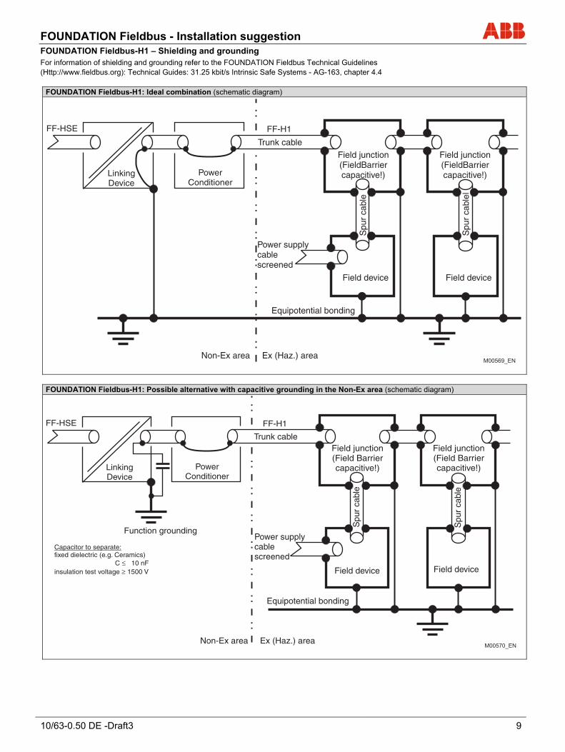
FOUNDATION Fieldbus-H1 – Shielding and grounding For information of shielding and grounding refer to the FOUNDATION Fieldbus Technical Guidelines (Http://www.fieldbus.org): Technical Guides: 31.25 kbit/s Intrinsic Safe Systems - AG-163, chapter 4.4
FOUNDATION Fieldbus-H1: Ideal combination (schematic diagram)
FF-HSE FF-H1
PowerConditioner
LinkingDevice
Trunk cableField junction(FieldBarriercapacitive!)
Field junction(FieldBarriercapacitive!)
Spu
r ca
ble
Spu
r ca
blel
Field device
Equipotential bonding
Power supplycablescreened
Non-Ex area Ex (Haz.) area
Field device
M00569_EN
FOUNDATION Fieldbus-H1: Possible alternative with capacitive grounding in the Non-Ex area (schematic diagram)
FF-HSE FF-H1
PowerConditioner
LinkingDevice
Function grounding
Non-Ex area Ex (Haz.) area
Trunk cable
Capacitor to separate:fixed dielectric (e.g. Ceramics)
C ≤≥
10 nFinsulation test voltage 1500 V
Power supplycablescreened
Equipotential bonding
Field device Field device
Spu
r ca
ble
Spu
r ca
ble
Field junction(Field Barriercapacitive!)
Field junction(Field Barriercapacitive!)
M00570_EN
FOUNDATION Fieldbus - Installation suggestion
10 10/63-0.50 DE
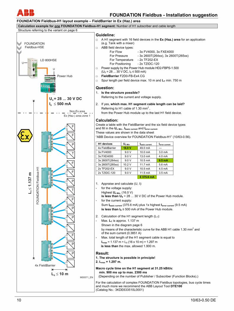
FOUNDATION Fieldbus-H1 layout example – FieldBarrier in Ex (Haz.) area Calculation example for one FOUNDATION Fieldbus-H1 segment: Number of H1 subscriber and cable length Structure referring to the variant on page 6
Guideline: A H1 segment with 16 field devices in the Ex (Haz.) area for an application
(e.g. Tank with a mixer)
ABB field device types: For Flow - 3x FV4000, 3x FXE4000 For Pressure - 3x 2600T(264xx), 3x 2600T(265xx) For Temperature - 2x TF202-EX For Positioning - 2x TZIDC-120 Power supply by the Power Hub module HD2-FBPS-1.500
(US = 28 ... 30 V DC, IS ≤ 500 mA)
FieldBarrier F2D0-FB-Ex4.CG
Spur length per field device max. 10 m and LT min. 750 m
Question: 1. Is the structure possible?
Referring to the current and voltage supply.
2. If yes, which max. H1 segment cable length can be laid?
Referring to H1 cable of 1.30 mm2 ,
from the Power Hub module up to the last H1 field device.
Calculation: Create a table with the FieldBarrier and the six field device types and fill in the Us Min., Ibasic current and Ierror current. These values are shown in the data sheet
“ABB Device overview for FOUNDATION Fieldbus-H1” (10/63-0.56).
H1 devices Us Min Ibasic current Ierror current
4x FieldBarrier 16.0 V 49.0 mA ---
3x FV4000 9.0 V 10.0 mA 3.0 mA
3x FXE4000 9.0 V 13.0 mA 4.0 mA
3x 2600T(264xx) 9.0 V 10.5 mA 9.5 mA
3x 2600T(265xx) 10.2 V 11.7 mA 5.6 mA
2x TF202-EX 9.0 V 10.5 mA 4.5 mA
2x TZIDC-120 9.0 V 11.5 mA 3.5 mA
Σ 375.6 mA
1. Appraise and calculate (U, I):
- for the voltage supply:
Highest Us Min. (16.0 V) is less than US = 28 ... 30 V DC of the Power Hub module.
- for the current supply:
Sum Ibasic current (375.6 mA) plus 1x highest Ierror current (9.5 mA)
is less than IS ≤ 500 mA of the Power Hub module.
2. Calculation of the H1 segment length (LT):
- Max. LT is approx. 1.137 m
Shown in the diagram page 6
by means of the characteristic curve for the ABB H1 cable 1.30 mm2 and of the sum current (0.3851 A)
- Max. total length of the H1 segment cable is equal to
Lmax = 1.137 m + LS (16 x 10 m) = 1.297 m is less than the max. allowed 1.900 m.
U
FOUNDATIONFieldbus-HSE
LD 800HSE
F
P
F
F
P
T
F
F
P
T
L 10 mS ≤
F
P
P
P
FO
UN
DAT
ION
Fie
ldbu
s-H
1
4x FieldBarrier
U
Power Hub
U = 28 ... 30 V DC
I 500 mA
S
S ≤
Ex (Haz.) area zone 1
Non-Ex area
L1.1
37
mT≤
M00571_EN
Result: 1. The structure is possible in principle! 2. Lmax = 1.297 m.
Macro cycle time on the H1 segment at 31.25 kBit/s: min. 900 ms up to max. 2300 ms (Depending on the number of Publisher / Subscriber (Function Blocks).)
For the calculation of complex FOUNDATION Fieldbus topologies, bus cycle times and much more we recommend the ABB Layout Tool DTE100 (Catalog No.: 3KDE633510L0001)

FOUNDATION Fieldbus - Installation suggestion
10/63-0.50 DE -Draft3 11
FOUNDATION Fieldbus-H1 layout example – Passive 4-way junction in Non-Ex area Calculation example for one FOUNDATION Fieldbus-H1 segment: Number of H1 subscriber and cable length Structure referring to the variant on page 7.
Guideline: A H1 segment with 16 field devices in the Non-Ex area for an application
(e.g. Tank with a mixer)
ABB field device types: For Flow - 3x FV4000, 3x FXE4000 For Pressure - 3x 2600T(264xx), 3x 2600T(265xx) For Temperature - 2x TF202 For Positioning - 2x TZIDC-120 Power supply by the Power Hub module HD2-FBPS-1.500
(US = 28 ... 30 V DC, IS ≤ 500 mA)
Passive 4-way junction NPJ460-NO
Spur length per field device max. 10 m and LT min. 750 m
Question: 1. Is the structure possible?
Referring to the current and voltage supply.
2. If yes, which max. H1 segment cable length can be laid?
Referring to H1 cable of 0.88 mm2 ,
from the Power Hub module up to the last H1 field device.
Calculation: Create a table with the six field device types and fill in the Us Min., Ibasic current and Ierror current. These values are shown in the data sheet
“ABB Device overview for FOUNDATION Fieldbus-H1” (10/63-0.56). H1 devices Us Min Ibasic current Ierror current
4x NPJ460-NO --- --- ---
3x FV4000 9.0 V 10.0 mA 3.0 mA
3x FXE4000 9.0 V 13.0 mA 4.0 mA
3x 2600T(264xx) 9.0 V 10.5 mA 9.5 mA
3x 2600T(265xx) 10.2 V 11.7 mA 5.6 mA
2x TF202 9.0 V 10.5 mA 4.5 mA
2x TZIDC-120 9.0 V 11.5 mA 3.5 mA
Σ 179.6 mA
1. Appraise and calculate (U, I):
- for the voltage supply:
Highest Us Min. (10.2 V) is less than US = 28 ... 30 V DC of the Power Hub module.
- for the current supply:
Sum Ibasic current (179.6 mA) plus 1x highest Ierror current (9.5 mA)
is less than IS ≤ 500 mA of the Power Hub module
2. Calculation of the H1 segment length (LT):
- Max. LT is > 1.900 m!
Shown in the diagram page 7
by means of the characteristic curve for the ABB H1 cable 0.88 mm2, the sum current (0.1891 A) and highest Us Min. (10.2 V).
- Max. total length of the H1 segment cable is equal to
Lmax = 1.900 m + LS (16 x 10 m) > 1.900 m!
Attention: Not exceed the max. allowed 1.900 m! Max. LT = 1.900 m - LS (16x 10 m) = 1.740 m!
U
FOUNDATIONFieldbus-HSE
LD 800HSE
F
P
F
F
P
T
F
F
P
T
L 10 mS ≤
F
P
P
P
4x NPJ460-NO
U
Power Hub
U = 28 ... 30 V DC
I 500 mA
S
S ≤
FO
UN
DAT
ION
Fie
ldbu
s-H
1
L1,7
40
mT≤
M00572_EN
Result: 1. The structure is possible in principle! 2. Lmax = 1.900 m. Macro cycle time on the H1 segment at 31.25 kBit/s:
min. 900 ms up to max. 2300 ms (Depending on the number of Publisher / Subscriber (Function Blocks).)
For the calculation of complex FOUNDATION Fieldbus topologies, bus cycle times and much more we recommend the ABB Layout Tool DTE100: (Catalog No: 3KDE633510L0001)
Contact us
10/6
3-0.
50 E
N R
ev. A
02.
2011Note
We reserve the right to make technical changes or modify the contents of this document without prior notice. With regard to purchase orders, the agreed particulars shall prevail. ABB does not accept any responsibility whatsoever for potential errors or possible lack of information in this document. We reserve all rights in this document and in the subject matter and illustrations contained therein. Any reproduction, disclosure to third parties or utilization of its contents - in whole or in parts – is forbidden without prior written consent of ABB. Copyright© 2011 ABB All rights reserved
3KXN050000R1001
ABB Automation Products GmbH Borsigstr. 2 63755 Alzenau Germany Phone: +49 551 905-534 Fax: +49 551 905-555 www.abb.com