Fiber Optic Shape Sensing - Lunalunainc.com/wp-content/uploads/2012/08/SS-00021-D... · Fiber Optic...
6
Revision 003 Document #: SS00021-D-TS June 21, 2013 Current State of Technology Luna Innovations Incorporated June 21, 2013 Fiber Optic Shape Sensing
Transcript of Fiber Optic Shape Sensing - Lunalunainc.com/wp-content/uploads/2012/08/SS-00021-D... · Fiber Optic...
Revision 003 Document #: SS00021-D-TS June 21, 2013
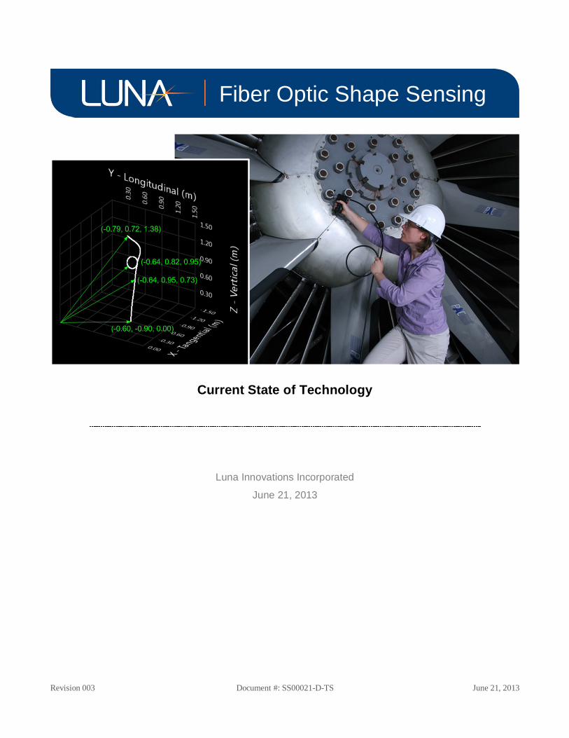
Current State of Technology
Luna Innovations Incorporated
June 21, 2013
Fiber Optic Shape Sensing
Fiber Optic Shape Sensing | 2
Revision 003 Document #: SS00021-D-TS June 21, 2013
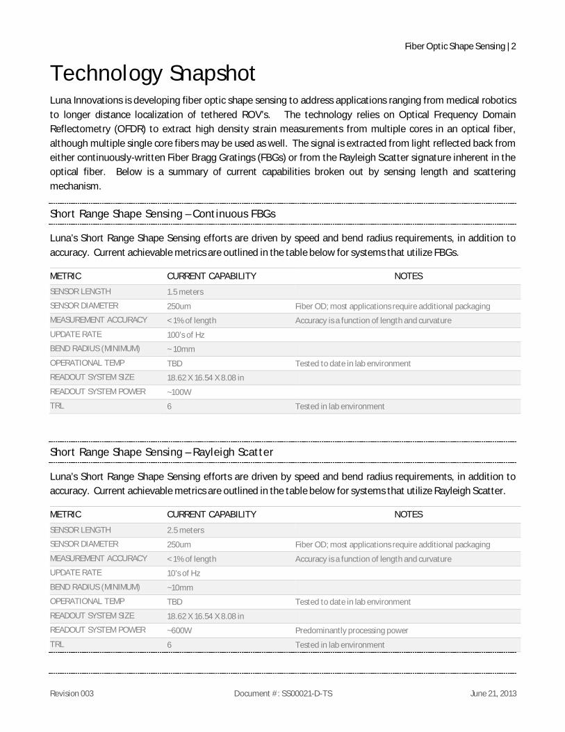
Technology Snapshot Luna Innovations is developing fiber optic shape sensing to address applications ranging from medical robotics to longer distance localization of tethered ROV’s. The technology relies on Optical Frequency Domain Reflectometry (OFDR) to extract high density strain measurements from multiple cores in an optical fiber, although multiple single core fibers may be used as well. The signal is extracted from light reflected back from either continuously-written Fiber Bragg Gratings (FBGs) or from the Rayleigh Scatter signature inherent in the optical fiber. Below is a summary of current capabilities broken out by sensing length and scattering mechanism.
Short Range Shape Sensing – Continuous FBGs
Luna’s Short Range Shape Sensing efforts are driven by speed and bend radius requirements, in addition to accuracy. Current achievable metrics are outlined in the table below for systems that utilize FBGs.
METRIC CURRENT CAPABILITY NOTES
SENSOR LENGTH 1.5 meters
SENSOR DIAMETER 250um Fiber OD; most applications require additional packaging
MEASUREMENT ACCURACY < 1% of length Accuracy is a function of length and curvature
UPDATE RATE 100’s of Hz
BEND RADIUS (MINIMUM) ~ 10mm
OPERATIONAL TEMP TBD Tested to date in lab environment
READOUT SYSTEM SIZE 18.62 X 16.54 X 8.08 in
READOUT SYSTEM POWER ~100W
TRL 6 Tested in lab environment
Short Range Shape Sensing – Rayleigh Scatter
Luna’s Short Range Shape Sensing efforts are driven by speed and bend radius requirements, in addition to accuracy. Current achievable metrics are outlined in the table below for systems that utilize Rayleigh Scatter.
METRIC CURRENT CAPABILITY NOTES
SENSOR LENGTH 2.5 meters
SENSOR DIAMETER 250um Fiber OD; most applications require additional packaging
MEASUREMENT ACCURACY < 1% of length Accuracy is a function of length and curvature
UPDATE RATE 10’s of Hz
BEND RADIUS (MINIMUM) ~10mm
OPERATIONAL TEMP TBD Tested to date in lab environment
READOUT SYSTEM SIZE 18.62 X 16.54 X 8.08 in
READOUT SYSTEM POWER ~600W Predominantly processing power
TRL 6 Tested in lab environment

Fiber Optic Shape Sensing | 3
Revision 003 Document #: SS00021-D-TS June 21, 2013
Extended Range Shape Sensing – Rayleigh Scatter
Luna’s extended range shape sensing is being developed primarily for tethered ROVs and towed acoustic hydrophone arrays. In both instances the bend radius, speed, and accuracy requirements are less stringent than those in short range applications; however, thermal variations and vibration requirements are tighter.
METRIC CURRENT CAPABILITY NOTES
SENSOR LENGTH 30 meters
SENSOR DIAMETER <0.5mm Fiber OD; most applications require additional packaging
MEASUREMENT ACCURACY ~ 1% of length Accuracy is a function of length and curvature
UPDATE RATE 0.2 Hz On a quadcore laptop
BEND RADIUS (MINIMUM) as low as 50mm Small bend radius specified at ~0.1 Hz refresh rate. Faster refresh increases min bend radius
OPERATIONAL TEMP TBD Tested in local indoor swimming pool
READOUT SYSTEM SIZE 18.62 X 16.54 X 8.08 in
READOUT SYSTEM POWER ~200W Predominantly processing power
TRL 5 Tested in swimming pool with iRobot’s Transphibian UUV
Short Range Shape Sensing Dynamic Demonstration:
The endpoint of a 2.2m shape sensing tether, traversed back and forth over 0.5m, yields an average time-synchronized RMS endpoint accuracy of 8.1mm or 0.37% by length over 20 cycles.
Figure 1 (left) Image of 2.2m shape sensing prototype system for coordinate measurement applications.
(top right) Orthographic rendering of measured shape sensing data in linear stage experiment.
(bottom right) Orthographic view of measured endpoint data over 20 cycles of linear motion.

Fiber Optic Shape Sensing | 4
Revision 003 Document #: SS00021-D-TS June 21, 2013
Short Range Shape Sensing Repeatability and Drift:
Repeatability of the endpoint measurement on a 2.5m shape sensor was tested over 16.5 hours on a system running at 10Hz. The endpoint standard deviation (3D position) was measured to be σ = 1.6mm (0.06% by length), or 3σ = 5.0mm (0.2% by length). A histogram of the measurement is shown below in Figure 2.
Figure 2. Endpoint measurement on a 2.5m shape sensing tether has repeatability of σ = 1.6mm (0.06% by length) over 16.5 hrs.
Extended Range Shape Sensing Demonstration:
A 30m shape sensing tether, configured in a complex 3D shape on laboratory tables (left image below), yields an RMS path measurement error1 of approximately 7.7cm (less than 0.4% by length) and a maximum path measurement error of approximately 13.5cm (1% by length).
Figure 3. 30m shape sensor demonstration: (left) rendering of sensor position, (right) measured data
1 Luna defines path measurement error as the distance between a physical test point and the closest point in the 3D shape measurement. Percent error by length is calculated as the point-by-point ratio of path error to the path length at each test point.
(mm) (mm)

Fiber Optic Shape Sensing | 5
Revision 003 Document #: SS00021-D-TS June 21, 2013
Technical Background
Optical Frequency Domain Reflectometry (OFDR)
Luna’s shape and position sensing technology is based on optical frequency domain reflectometry (OFDR). Using the basic network topology shown in Figure 4, OFDR provides a means of measuring distributed strain along an optical fiber with extremely high resolution. Using state-of-the-art phase-tracking techniques to compare Rayleigh scatter measurements with a baseline reference state, Luna’s OFDR system can achieve +/- 1.6με resolution over 1.5mm [1] and better than 50m/point spatial resolution [2]. The OFDR topology shown in Figure 4 is the basis for a number of Luna’s core technologies, including the OBRTM optical network interrogator and ODiSITM distributed sensing system.
A tunable laser source (TLS) is split at a 2x2 coupler into two arms of a measurement interferometer, one of which contains the strain sensing fiber. The interference pattern from this interferometer is measured using a polarization-diverse detection scheme, using a polarization controller (PC) to balance the signals on the S and P detectors. A second (trigger) interferometer with a known delay is used to compensate for nonlinearities in the laser tuning.
Precision Shape Sensing using OFDR
Shape and position sensing is performed through measurement of axial twist and curvature along the length of a monolithic, helical multi-core optical fiber (Figure 5). OFDR techniques are used to monitor distributed strain along the lengths of the center core and the three outer cores [3]. Members of this “triad” of outer cores are spaced at 120o azimuths, at a fixed radius from the center core. This geometry allows the shape sensing fiber to convert the multi-core distributed strain measurement to three-dimensional distributed position (shape).
Under curvature, each of the outer cores experiences alternating states of tension and compression on its helical path through the bend. The center core, which is precisely located in the center of the sensing fiber, experiences negligible first-order strain. The three outer cores exhibit sinusoidal
Figure 4. Basic OFDR network
Figure 5. (A) SEM micrograph of shape sensing fiber, sensing triad in red; (B) Illustration of helical cores along length of fiber;
(C) Typical four-core strain response to external curvature

Fiber Optic Shape Sensing | 6
Revision 003 Document #: SS00021-D-TS June 21, 2013
strain responses, each 120o out of phase with the others. By comparing the amplitude and phase of these three strain curves, one can determine the applied bend radius and its direction relative to the fiber’s coordinate system.
Under twist, all of the three outer cores experience a common-mode strain. If the fiber is twisted in the direction of the helix, a tensile strain is applied to the triad of outer cores. A twist in the opposite direction places the outer cores in compression. By observing the magnitude of the common-mode strain signal, one can determine the distributed state of twist along the length of the sensing fiber. Strain measurements in the center core are used as a reference to compensate for tensile strain and temperature changes in the shape sensing fiber. This twist measurement is then used to convert the 3D curvature measurement from the fiber’s local coordinate system to a fixed “master” 3D grid, defined by the position and vector direction of the fixed launch point at the start of the shape sensing fiber.
References
[1] D. K. Gifford, M. E. Froggatt, and S. T. Kreger, “High precision, high sensitivity distributed displacement and temperature measurements using OFDR-based phase tracking,” in Proc.SPIE, 2011, vol. 7753, p. 77533I.
[2] B. J. Soller, D. K. Gifford, M. S. Wolfe, and M. E. Froggatt, “High resolution optical frequency domain reflectometry for characterization of components and assemblies,” Optics Express, vol. 13, no. 2, pp. 666–674, 2005.
[3] M. E. Froggatt, J. W. Klein, D. K. Gifford, and S. T. Kreger, “Optical Position and/or Shape Sensing,” U.S. Patent 12/874901.