THE USE OF DISTRIBUTED FIBER OPTIC STRAIN SENSING IN …
8
THE USE OF DISTRIBUTED FIBER OPTIC STRAIN SENSING IN ORDER TO CONDUCT QUALITY ASSURANCE AND QUALITY CONTROL FOR GROUND SUPPORT Vlachopoulos, N. Civil Engineering Department, Royal Military College of Canada, Kingston, Ontario, Canada Forbes, B Department of Geological Sciences and Geological Engineering, Queen’s University, Kingston Ontario, Canada Cruz, D. Civil Engineering Department, Royal Military College of Canada, Kingston, Ontario, Canada This paper focuses on the development of fiber optic strain sensing and its use in order to ensure that support elements have been installed according to specifications (Quality Control) and that they are performing correctly (Quality Assurance); both in a controlled laboratory environment and in-situ. Results of the testing program demonstrated that a developed fiber optic technique could determine material flaws within grouted rock support installation as well as determine the strain and capacity of support elements in the lab and in-situ. i.e. during pull-out tests. As well, results demonstrated the capability of the optical technique to capture expected loading mechanisms of the support elements throughout their serviceability life, agreeing well with numerical and theoretical predictions. The optical technique has been successfully employed on- site at mines and tunnels around the globe. Cette recherche a été consacrée à la mise en place d’une technique permettant l’installation in situ du capteur optique avec des boulons d'ancrage et d’autres éléments de support. Le développement d’une telle technique optique est un projet considérable. Cet article se concentre sur le développement et l’utilisation de cette technologie afin de s’assurer que les éléments de support conformes aux spécifications (contrôle de qualité) et fonctionnent (assurance de qualité) dans un environnement de laboratoire contrôlé et in situ. Les résultats du programme d'essais ont démontré que cette technique peut déterminer les défauts dans l’installation de support dans la roche cimenté, la tension et la capacité des éléments de support en laboratoire et in situ, c’est-à-dire pendant les essais d’arrachement. De plus, les résultats ont démontré l’aptitude de telle technique afin de capturer les mécanisme de chargement attendus ces éléments de support tout au long de leur durée de vie, ce qui concorde aux prédictions numériques et théoriques. Cette technique a été utilisée avec succès sur site, dans les mines et les tunnels autour du monde 1 INTRODUCTION Within the design of support for underground excavations and openings, local instability issues arise around the immediate material surrounding an excavation (i.e. zone of plasticity (Vlachopoulos & Diederichs, 2009) or excavation damage zone (Diederichs, et. al., 2004)). The stability of the opening is dependent on the stress and conditions of the ground that is adjacent to the excavation boundary. Under these conditions, ground support refers to the steps taken and materials used in order to maintain the load bearing capacity of the rock near the opening of an excavation (Brady & Brown, 2004). However, how can one ascertain if the rock bolt pattern, for instance, (in conjunction with the rest of the support design) is optimized? Also, how can one determine the ‘effectiveness’ of the bolt itself in terms of type used, length, diameter, anchoring, grout etc. in conjunction with the ground conditions? Therefore, there is an implicit need for a correct and accurate evaluation of the installation and performance of a ground support system installation (with regards to tunnels, mines and other geotechnical works); This is critical to the structural integrity, safety and economics of the construction process. An instrumentation and monitoring program capable of determining that the ground support has been installed and performs according to design specifications needs to be considered. Within this context, a novel distributed optical strain sensing (DOS) technology has been developed and implemented with ground support elements. Unlike conventional, discrete strain measurement methods, the optical technology captures a distributed strain profile along the length of a standard, low-cost, single mode optical fiber (i.e. 0.65 millimeter spatial resolution). In this regard, this research has been devoted to developing a technique whereby the optical sensor is capable of being installed with rock bolt and other ground support elements to be used as primary support in-situ. The development of such an optical technique is a non-trivial undertaking and has been well documented by the authors (Forbes et al., 2018, Forbes et al., 2017, Forbes, 2015). 2 LABORATORY TESTING – AXIAL PULLOUT TESTS A series of pullout tests were carried out in the structures laboratory at the Royal Military College of Canada. Tests were carried out using a 322.41 Material Testing System (MTS) that has a capacity of 500 kN in tension (Figure 1).
Transcript of THE USE OF DISTRIBUTED FIBER OPTIC STRAIN SENSING IN …

THE USE OF DISTRIBUTED FIBER OPTIC STRAIN SENSING IN ORDER TO CONDUCT QUALITY ASSURANCE AND QUALITY CONTROL FOR GROUND SUPPORT Vlachopoulos, N. Civil Engineering Department, Royal Military College of Canada, Kingston, Ontario, Canada Forbes, B Department of Geological Sciences and Geological Engineering, Queen’s University, Kingston Ontario, Canada Cruz, D. Civil Engineering Department, Royal Military College of Canada, Kingston, Ontario, Canada This paper focuses on the development of fiber optic strain sensing and its use in order to ensure that support elements have been installed according to specifications (Quality Control) and that they are performing correctly (Quality Assurance); both in a controlled laboratory environment and in-situ. Results of the testing program demonstrated that a developed fiber optic technique could determine material flaws within grouted rock support installation as well as determine the strain and capacity of support elements in the lab and in-situ. i.e. during pull-out tests. As well, results demonstrated the capability of the optical technique to capture expected loading mechanisms of the support elements throughout their serviceability life, agreeing well with numerical and theoretical predictions. The optical technique has been successfully employed on-site at mines and tunnels around the globe. Cette recherche a été consacrée à la mise en place d’une technique permettant l’installation in situ du capteur optique avec des boulons d'ancrage et d’autres éléments de support. Le développement d’une telle technique optique est un projet considérable. Cet article se concentre sur le développement et l’utilisation de cette technologie afin de s’assurer que les éléments de support conformes aux spécifications (contrôle de qualité) et fonctionnent (assurance de qualité) dans un environnement de laboratoire contrôlé et in situ. Les résultats du programme d'essais ont démontré que cette technique peut déterminer les défauts dans l’installation de support dans la roche cimenté, la tension et la capacité des éléments de support en laboratoire et in situ, c’est-à-dire pendant les essais d’arrachement. De plus, les résultats ont démontré l’aptitude de telle technique afin de capturer les mécanisme de chargement attendus ces éléments de support tout au long de leur durée de vie, ce qui concorde aux prédictions numériques et théoriques. Cette technique a été utilisée avec succès sur site, dans les mines et les tunnels autour du monde
1 INTRODUCTION Within the design of support for underground excavations and openings, local instability issues arise around the immediate material surrounding an excavation (i.e. zone of plasticity (Vlachopoulos & Diederichs, 2009) or excavation damage zone (Diederichs, et. al., 2004)). The stability of the opening is dependent on the stress and conditions of the ground that is adjacent to the excavation boundary. Under these conditions, ground support refers to the steps taken and materials used in order to maintain the load bearing capacity of the rock near the opening of an excavation (Brady & Brown, 2004). However, how can one ascertain if the rock bolt pattern, for instance, (in conjunction with the rest of the support design) is optimized? Also, how can one determine the ‘effectiveness’ of the bolt itself in terms of type used, length, diameter, anchoring, grout etc. in conjunction with the ground conditions? Therefore, there is an implicit need for a correct and accurate evaluation of the installation and performance of a ground support system installation (with regards to tunnels, mines and other geotechnical works); This is critical to the structural integrity, safety and economics of the construction process. An instrumentation
and monitoring program capable of determining that the ground support has been installed and performs according to design specifications needs to be considered. Within this context, a novel distributed optical strain sensing (DOS) technology has been developed and implemented with ground support elements. Unlike conventional, discrete strain measurement methods, the optical technology captures a distributed strain profile along the length of a standard, low-cost, single mode optical fiber (i.e. 0.65 millimeter spatial resolution). In this regard, this research has been devoted to developing a technique whereby the optical sensor is capable of being installed with rock bolt and other ground support elements to be used as primary support in-situ. The development of such an optical technique is a non-trivial undertaking and has been well documented by the authors (Forbes et al., 2018, Forbes et al., 2017, Forbes, 2015).
2 LABORATORY TESTING – AXIAL PULLOUT TESTS
A series of pullout tests were carried out in the structures laboratory at the Royal Military College of Canada. Tests were carried out using a 322.41 Material Testing System (MTS) that has a capacity of 500 kN in tension (Figure 1).

The MTS was modified by utilizing an arrangement of two 1 inch (25.4 mm) steel plates along with two ¾ inch (19 mm) threaded bars in order to fix concrete specimens containing cement grouted rebar. This allowed for the axial load to be applied to the rebar in a controlled manner.
Figure 1. Laboratory Testing - Pullout test apparatus
A distributed optical strain sensing (DOS) technique based on optical frequency domain reflectometry was coupled with the rebar (rock bolt) specimens in accordance with Forbes et al., (2018). This included positioning a low-cost optical sensor along a pair of diametrically opposing machined grooves and bonding the sensor using a propriety adhesive. The sensor was looped at one end of the specimen such that both sides were monitored using a single optical sensor. Monitoring opposing sides of the specimen also allowed bending to be compensated for. An example of the sensor is presented in Figure 2. Figure 2. Schematic of positioning of optical fiber used throughout testing.
The methodology, series of pull-out tests, and results are included in Vlachopoulos et al. (2018). Further to these noted results were the specific mechanisms and behaviours that were observed at such low detection limits. This level of detection can lead to a better understanding of the mechanistic behaviour of rock bolt systems as well as insight into quality assurance programs concerning the integrity of support installation.
Figure 3. Axial pull-out test. Strain profile along the length (Side 1) of the steel pipe at various applied axial loads.
Results from an axial pullout test using grout are shown in Figure 3. During the testing it was evident using the optical technique that an anomaly existed within the grout or concrete block as unloading and reloading of the sample produce similar results (i.e. the instrumentation was functioning properly). Post-testing, the grouted length was cut from the concrete specimen. Aligned with the optical instrumentation, fracturing of the grout extending approximately 150 mm from the load to toe end was discovered (Figure 4 top). A circular void in the grout was also identified at approximately 150 mm from the load end of the grout, Figure 4 bottom. Comparing these post-test discoveries of the grout with the axial strain profiles verifies the accuracy and scale at which the optical instrumentation operates and allows for the detection of such ‘defects’ in the installation of such specimens. Such observations using this technique were noted by Vlachopoulos and Forbes (2015). Insight of mechanisms associated with the bolt-grout interface as well as the bolt-rock interface can also be gained using this fiber optic technique. The results seen in Figure 5 correspond to the strain profile of the embedded section of the rebar as observed during incremental load testing. The strain profiles are shown at selected applied
LVDT
Test
specimen
Analyzer unit
Fiber
optic
MTS
Actuator /
Load Cell
Anomaly

loads. For lower loads, the strain is seen to generally decay away from the collar of the borehole to the end of the embedded section of the rebar. Furthermore, the jaggedness (i.e. the periodic disturbances) of the strain profiles correspond with the spacing of the bolt ribs – as the ribs cause the cross sectional area of the bolt to change. This is akin to the results described by Hyett et al. (2013). The section of the rebar which extends outside of the concrete cylinder is clearly distinct as there is no strain that develops along this segment of the rebar. This is due to the fact that this end of the rebar is free (i.e. limit equilibrium. The fiber optic technique was also able to capture the response of the rebar post non-critical failure of the system (i.e. the fiber optic is still able to withstand further loading). For this particular test, a brittle failure mechanism caused the concrete to radially split along two visible regions of the concrete cylinder. The radial splitting of the concrete cylinder decreased the radial confinement provided to the rebar and grout by the surrounding concrete. Accordingly, the amount of contact that existed between the rebar- grout and grout-concrete, post failure, was not enough to adequately mobilize the entire shear strength available at one of the interfaces. The flat region seen in the strain profile of the rebar near the borehole collar (i.e., from 0.00-0.05m, Figure 5) is indicative of the region along the embedment length of the rebar were decoupling at an interface has occurred. The efficiency of load transfer along this region therefore decreased. Therefore, the grouted rebar system could not carry any additional load. This residual load bearing capacity of the specimen was mainly provided by the region of the rebar 0.1 m into the embedment length and further on where the grout and borehole and rebar and grout maintained a stronger bond. Indicatively, conventional instrumentation (LVDT) also captured the slip that occurred through incremental loading during the pull-out test (Figure 6).
Figure 6. Pullout test slip result As can be seen, slip began to take place along the bolt-grout interface at a load of ~100 kN (Figure 6). This proceeded until a peak load of 162 kN was reached. A total amount of 1.7 mm of slip was recorded. Analysis of a cutaway of the specimen shows that the bond between the rebar and grout remained relatively intact throughout the loading of the bolt (Figure 7). Forensics conducted post testing demonstrates that past the region where slip began to take place, the slip occurred along the grout-borehole
(b)
Figure 4. Axial Pullout Test. Post-test removal of the grouted length from the concrete block. (Top) Fracture extending 150 mm along the grout from the load end, aligned with the optical fiber; (Bottom) Void in the grout approximately 150 mm from the load end.
Figure 5. Distributed Fiber Optic strain profile results for pullout test of rebar; post failure response.

interface. The shear strength past the onset of slip is therefore provided mainly by the friction created as the grout moves along the grout-borehole interface. This observation provides mechanistic evidence of the slip recorded with conventional instrumentation and that which was visually observed (Figure 8, Figure 9).
Figure 9. Bolt-grout and grout-concrete interface conditions post-testing (i.e. the effects of an improperly prepared borehole annulus).
Specimens were also found to fail at the rebar-grout interface, especially with longer embedment lengths. An inspection of these failed specimens detailed no significant grout voids throughout their length. As well, the grout was found to be intact. These results indicate that that mechanical interlocking capacity between the bolt ribs and the grout (assumed to provide the primary shear resistance) is exceeded in the form of shearing at the rebar-grout interface. The fiber optic strain sensing technique combined with conventional instrumentation was able to capture these effects. 3 COMPARISON OF LABORATORY AND FIELD
TESTING - ROCK BOLT AXIAL STRESS DISTRIBUTION TESTING
The previous section confirmed the applicability of the fiber optic technique to be able to capture relevant mechanisms and its potential to be used for quality assurance purposes. The question remained if this technique could be transferred to the field for these purposes. As such, a field component was trialed and selected concepts and results are noted within this section. The coaxial pull-out test is perhaps the most common assessment of a fully grouted rock bolt (ISRM 1974, 1984; ASTM D4435-13e1 2013). This assessment consists of installing a rock bolt support member in accordance with the standard procedures of a given site and subsequently applying a controlled coaxial loaded to the rock bolt member. The applied load and corresponding displace-ment of the rock bolt are both recorded in order to obtain a description of the rock bolt system yield and ultimate
Specimen
Undisturbed
Ridges
Grout
40 mm
Figure 7. Cross section of pullout test sample.
Grout displaced outside of borehole
Grout
Support Element with Fiber Optic
Specimen
Figure 8. Movement of grout outside of borehole.

capacity (both load and displacement capacities) as well as the stiffness of the system throughout its full serviceability life. This is often conducted in situ by using a hollow plunger hydraulic cylinder to apply load to the rock bolt from within the excavation, but may also be replicated under laboratory conditions by replacing the host rock mass with a confining medium (e.g., a metallic pipe, concrete block, or rock mass block). Nevertheless, many rock bolt coaxial pull-out test campaigns neglect the load distribution along the rock bolt member. This is of substantial support design significance in understanding how the given “bonded length” of the rock bolt (or length of the rock bolt that has been cement/resin grouted to the rock mass) distributes load to/from the surrounding rock mass. By utilizing the discussed DOS technique, the load distribution profile can be distinguished every 0.65 mm along a rock bolt member. This is demonstrated to augment the value of a conventional pull-test using selected field and laboratory results.
The load distribution data for both the field and laboratory examples discussed herein have been obtained using Gr. 60 (i.e., 413 MPa yield strength) steel rebar members that have been instrumented with a pair of diametrically opposed optical fiber sensing lengths. These instrumented support members both use a single optical fiber sensor to monitor the two sensing lengths by looping the optical fiber sensor at one end of the member as described previously. This allows the coaxial strain (𝜀𝑐𝑜𝑎𝑥𝑖𝑎𝑙) along the rebar to determined by averaging the strain measurements along opposing sides of the rock bolt; eliminating any bending moment induced strain, Eq. 1 (where SL refers to sensing length).
𝜀𝑐𝑜𝑎𝑥𝑖𝑎𝑙 = 𝜀𝑥
𝑆𝐿 1+𝜀𝑥𝑆𝐿 2
2
[1]
Strain measured along the entirety of an optical fiber sensor for a selected field pull-out test is presented in Figure 10. This test corresponds to a sandstone outcrop
Figure 10: Field coaxial pull-test. Top: Schematic depiction of the optical fiber sensor along the rock bolt member. The optical sensor loops at position of the mechanical expansion anchor at the toe of the bolt. Bottom: Strain measured along the entirety of the optical fiber sensors (or both sensing lengths of the rock bolt) at various level of applied load. Note: Positive strain is extensile and negative strain is contractive. The sensing length is approximately 1 m.
Lo
op
Lo
op

installation of 19.05 mm diameter rock bolt specimen. The rock bolt was installed into a 0.80 m long and 32 mm diameter drilled and washed borehole using a mechanical expansion anchor and 0.30 m of cement grout (0.4 W:C) at
the toe; refer to Figure 11. Load was applied during this test using a 30-tonne hydraulic cylinder. A similar pull-test configuration from an underground trial is presented in Figure 12. Applying Eq. 1, and multiplying by the Young’s Modulus of the steel rebar (E), the strain profiles presented in Figure 10 are used to plot the coaxial stress distribution along the length of the rock bolt member, Figure 13. In addition, the shear traction distribution between the rock bolt and the grout interface can be derived according to Eq. 2 (Farmer, 1975), where 𝑟𝑏 is the radius of the steel rebar
and 𝑛 is the given strain measurement position.
𝜏𝑥 =𝑟𝑏𝐸
2(
𝜀𝑐𝑜𝑎𝑥𝑖𝑎𝑙𝑛 − 𝜀𝑐𝑜𝑎𝑥𝑖𝑎𝑙
𝑛−1
𝑥𝑛 − 𝑥𝑛−1 ) [2]
For comparison with the field test measurements, a selected laboratory pull-test is presented. This test arrangement consisted of a 0.90 m long Gr. 60 steel rebar that was fully cement grouted (0.4 W:C) in a 0.55 m long and 32 mm diameter borehole drilled into a 0.20 m diameter concrete (40 MPa UCS) cylinder (Vlachopoulos et al. 2018). A 0.12 m segment of the rebar was extended
Figure 11: Upper: Field pull-out test arrangement. Lower: Laboratory pull-out test arrangement.
Figure 12: Example underground pull-out test apparatus showing both the hydraulic assembly used to apply load and the DOS measurement unit to record the load distribution along the rock bolt member.
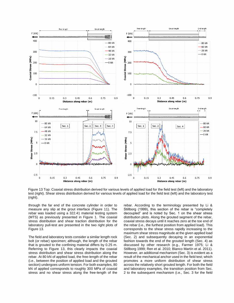
through the far end of the concrete cylinder in order to measure any slip at the grout interface (Figure 11). The rebar was loaded using a 322.41 material testing system (MTS) as previously presented in Figure 1. The coaxial stress distribution and shear traction distribution for the laboratory pull-test are presented in the two right plots of Figure 13. The field and laboratory tests consider a similar length rock bolt (or rebar) specimen; although, the length of the rebar that is grouted to the confining material differs by 0.25 m. Referring to Figure 13, this clearly impacts the coaxial stress distribution and shear stress distribution along the rebar. At 80 kN of applied load, the free-length of the rebar (i.e., between the position of applied load and the grouted section) undergoes uniform tension. For both examples, 80 kN of applied corresponds to roughly 300 MPa of coaxial stress and no shear stress along the free-length of the
rebar. According to the terminology presented by Li & Stillborg (1999), this section of the rebar is “completely decoupled” and is noted by Sec. 1 on the shear stress distribution plots. Along the grouted segment of the rebar, coaxial stress decays until it reaches zero at the toe end of the rebar (i.e., the furthest position from applied load). This corresponds to the shear stress rapidly increasing to the maximum shear stress magnitude at the given applied load (Sec. 2) and subsequently decaying in an exponential fashion towards the end of the grouted length (Sec. 4) as discussed by other research (e.g., Farmer 1975; Li & Stillborg 1999; Ren et al. 2010; Blanco Martín et al. 2011). However, an additional mechanism (Sec. 3) is evident as a result of the mechanical anchor used in the field test; which promotes a more uniform distribution of shear stress across the relatively short grouted length. For both the field and laboratory examples, the transition position from Sec. 2 to the subsequent mechanism (i.e., Sec. 3 for the field
Figure 13 Top: Coaxial stress distribution derived for various levels of applied load for the field test (left) and the laboratory test (right). Shear stress distribution derived for various levels of applied load for the field test (left) and the laboratory test (right).

test and Sec. 4 for the laboratory test) remains constant. This conveys that the deformation is compatible across the grouted length and that no decoupling has occurred at the rebar-grout or grout-confining medium interface. The non-linearity of the shear stress distribution along fully grouted rock bolts necessitates a high spatial resolution of measurements along the member’s length. While this can be accomplished through a dense positioning of discrete sensing technologies (e.g., electrical strain gauges), it is not practical for an intensive parametric study or field study (many lead-wires to manage and protect). 4 DISCUSSION AND CONCLUSIONS The micro-mechanistic response of axially loaded rock bolts is non-trivial, especially within jointed and fractured rock masses. The results included herein highlight the use of distributed fiber optic sensing for mechanistic determination purposes as well as its ability to determine material / installation / design flaws for quality assurance purposes. The fiber optic sensing technique is a state-of-the-art strain measuring technology with an unprecedented spatial resolution of 0.65 mm. The selected results outlined in this paper as part of a larger testing and research program by the authors showed explicitly that interaction mechanisms can be captured by this technology and is further validated by visual, forensic investigations of tested samples post testing as well as with conventional instrumentation that was used in tandem with the fiber optic technique. The use of the fiber optic technique made it possible to capture complex support behaviour not before captured by conventional means of instrumenting rock bolts. Further confidence on the practical application and utilization of this technique was provide by the field trials that were highlighted in this paper. Pull-out tests were effectively conducted in situ within a true operational setting. The planning and design of the inclusion of such a sensing technique in conjunction with the support element and pull out apparatus need to be deliberate. There are many factors that need to be taken into consideration when designing and ruggedizing the technique to be used in situ. For example, the fiber optic requires to be protected and to provide access from the rock bolt (rebar) to the analyzer while the bolt is being tested. The testing apparatus in situ needs to take this into consideration. The technique also can provide insight into the type of rock bolt installation that is being conducted and not only determine the effectiveness of the bolt system (i.e. the use and effectiveness of mechanical anchor, type/amount of grout) but also optimize the support design. The DOS method has excellent potential to play a significant role in quality control and quality assurance with respect to ground support. ACKNOWLEDGEMENTS The authors wish to acknowledge the support of the following industrial as well as governmental sponsors: Natural Sciences and Engineering Council of Canada (NSERC), the Canadian Department of National Defence (DND), Yield Point Inc. and The Royal Military College (RMC) Green Team.
REFERENCES Blanco Martín, L., Tijani, M., and Hadj-Hassen, F. 2011. A
new analytical solution to the mechanical behaviour of fully grouted rockbolts subjected to pull-out tests. Constr Build Mater, 25, 749–55.
Brady , B. H., & Brown, E. T. (2004). Rock Mechanics for Underground Mining. New York: Kluwer Academic
Publishers.
Diederichs, M. S., Kaiser, P. K., & Eberhardt, E. (2004). Damage initiation and propagation in hard rock during tunneling and the influence of near-face stress rotation. International Journal of Rock Mechanics and Mining Sciences, 41(5), 785-812.
Farmer, I.W. 1975. Stress distribution along a resin grouted rock anchor. Int J Rock Mech Min Sci Geomech Abstr, 12, 347–51.
Forbes, B., Vlachopoulos, N., and Hyett, A.J. 2018. The application of distributed optical strain sensing to measure the strain distribution of ground support members. FACETS, 3, 195-226.
Forbes, B., Vlachopoulos, N., Hyett, A.J., and Diederichs, M.S. 2017. A new optical sensing technique for monitoring shear of rock bolts. Tunnelling and Underground Space Technology, 66, 34-46.
Forbes, B. 2015. The application of distributed optical sensing for monitoring support in underground excavations, MASc Dissertation, Department of Geological Sciences & Geological Engineering, Queen’s University, Kingston, Canada.
Hyett, A. J., Forbes, B., & Spearing, S. (2013). Enlightening Bolts: Using Distributed Optical Sensing to Measure the Strain Profile along Fully Grouted Rock Bolts. Proceedings of the 32nd International Conference on Ground Control in Mining, (pp. 107-112). Morgantown, VW.
Li C., and Stillborg, B. 1999. Analytical models for rock bolts. Int J Rock Mech Min Sci, 36, 1013–1029.
Ren, F.F., Yang. Z.J., Chen, J.F., and Chen, W.W. 2010. An analytical analysis of the full-range behaviour of grouted rockbolts based on a tri-linear bond–slip model. Constr Build Mater, 24, 361–70.
Vlachopoulos, N., & Diederichs, M. S. (2009). Improved longitudinal displacement profiles for convergence confinement analysis of deep tunnels. Rock mechanics and rock engineering, 42(2), 131-146.
Vlachopoulos, N., Cruz, D., and Forbes, B. 2018. Utilizing a Novel Fiber Optic Technology to Capture the Axial Response of Fully Grouted Rock Bolts. Journal of Rock Mechanics and Geotechnical Engineering, JRMGE-2017-225, V10 N3 2018.
Vlachopoulos, N. & Forbes, B., 2015. Temporary Tunnel Support Strategies: Optimization and Testing. Proc. of the ITA WTC 2015 Congress and 41st General Assembly: SEE Tunnel: Promoting Tunneling in SEE Region, Dubrovnik, Croatia.