February 2013 TOLLWAY MANUALS AND STANDARDS PRESENTATIONS 1.
61
February 2013 TOLLWAY MANUALS AND STANDARDS PRESENTATIONS 1
-
Upload
berenice-cobb -
Category
Documents
-
view
214 -
download
0
Transcript of February 2013 TOLLWAY MANUALS AND STANDARDS PRESENTATIONS 1.

February 2013
TOLLWAY MANUALSAND STANDARDSPRESENTATIONS
1
Housekeeping Items3 PDH’s (By ACEC)ACEC & Tollway FTP Site
(Access Presentations)RestroomsSmokersSilence Cell PhonesQuestions
2

3
Publication Presenter
Introductions Mr. Matt Lehan
Opening Remarks Mr. Paul Kovacs
Tollway Standard Drawings Ms. Bridget Malinowski
Web Based Management System Mr. Dave Morris
Design Section Engineers Manual Mr. Jason Martin
Construction Managers Manual Mr. Nabil Fahoum
Structure Design Manual Mr. Art Nowak
Drainage Design Manual Mr. Edward Yousif
Break

4
Publication Presenter
Guidelines for Roadway Illumination Mr. John Farsatis
Roadway Design Criteria Mr. Tracy Borchardt
Traffic Barrier Guidelines Mr. Tracy BorchardtErosion and Sediment Control, Landscape Design Criteria Mr. Brian Smith
Signage and Markings Guidelines Ms. Bridget MalinowskiRoadway Traffic Control and Communications Manual Ms. Bridget Malinowski

Mr. Paul D. Kovacs, P.E.
Chief Engineer
5

Bridget Malinowski February 2013
TOLLWAY STANDARDS
6

SECTION A
Roadway Pavement
7

Section A - Summary Revisions
8

A 18 Precast Slabs
9

SECTION B
Drainage Structures
CurbsCurb and Gutter
Ditches
10

B1-Gutter Detail
11
Concrete Gutter Overlay

B1-Gutter and Curb Detail
12
Crack Control Joints Placed at 15’-0” CentersWith Asphalt Shoulders

B8- Type G-2 Modified Frame & Grate
13
Neenah: R 3508-B2

B24-Pipe Underdrains
14

SECTION C
GuardrailMedian Barrier
15

C1- Galvanized Steel Plate Beam Guardrail
9’ Post Identification(Stamp Both Sides)
16

C1- Galvanized Steel Plate Beam Guardrail
17
Modified Aggregate Shoulders Special Type C from 3” to 6” Depth.

Traffic Barrier TerminalsC6-Traffic Barrier Terminal Type T1 (Special)C7-Traffic Barrier Terminal Type T2C8-Traffic Barrier Terminal Type T5C9-Traffic Barrier Terminal Type T6C10-Traffic Barrier Terminal Type T6-BC12-Traffic Barrier Terminal Type T1-A
Modified Aggregate Shoulder Special Type C Depth from 3" to 6"
18

C3-Single Face Reinforced Concrete Barrier
19
New Gutter Transition

C5- Concrete Barrier , Double Face 42”
20
New Gutter Transition

C4- Concrete Shoulder Barrier Transition
21
Increased Crash Wall HeightFrom 4’-6” to 5’-0”.

C6 Traffic Barrier Terminal Type T1(Special)
Traffic Barrier Terminal Type T1 (Special)
All steel post system
22

C12 Traffic Barrier Terminal Type T1-A (Special)
All steel post system
Traffic Barrier Terminal Type T1-A (Special)
23

C13- Concrete Median Barrier Transition at Bridge Piers
24
Increased Crash Wall HeightFrom 4’-6” to 5’-0”.
Extended Transition Taper Length From 28' to 30'.

SECTION D
Roadway Appurtenances
25

D1-Right of Way Fence
26
Removed Material Type for Concrete Footing.

D2-Symbols & Patterns
27
New Symbols for Utility and Electric Items

D4-Delineators
28
Revised Permanent Delineation Spacing

D4-Delineators
29
New Temporary Delineation Spacing

D5- Permanent Pavement Markings
30
Revised Edge Line Offset from outside shoulder from 4” to 6”.

D6-Pavement Marking
6” Dotted Line, White3’ Line 9’ Gap
31

D8-Raised Pavement Markers
RPM Detail C Revised for Placement with6” Dotted Line, 3’ Line 9’ GapOne-Way Crystal Marker1 each at 48’ Centers
32

SECTION E
33
Maintenance of Traffic

E1-Construction Signs
34

E3-Lane Closure Details
35
New Standard for Three Lane Closure.
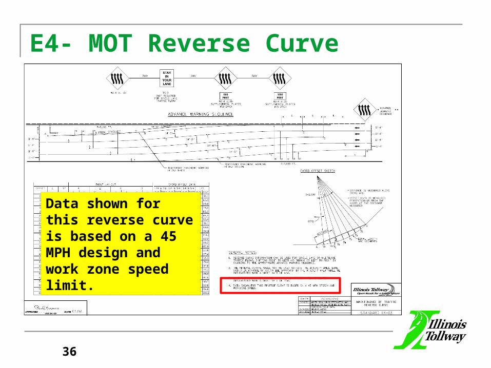
E4- MOT Reverse Curve
36
Data shown for this reverse curve is based on a 45 MPH design and work zone speed limit.

E7- Emergency Pull Out Area
37
Revised Length of Pull-Out Area to Accommodate Standard TCB Lengths.

SECTION F
Sign Structure
38
Revisions to be Released March 2013

Overhead Sign Structure, Span Type-Aluminum
Span Type- Redesigned For a 15’ Deep Sign Panel Over 75% of Span Length.
39

Overhead Sign Structure, Cantilever Type-Steel
Cantilever Type- Redesigned For 18’ Deep Sign Panel Over 75% of the Arm Length.
Maximum Panel Width Increased to 24’.
40

Overhead Sign Structure, Cantilever Type- Circular Foundation
Minimum Post outside diameter increased from 16” to 18”.Drilled shaft depth for all foundation types was increased.
41

Unshielded Foreslope 1:6 or Flatter
Breakaway Sign Support Details
42

Milepost Marker
43

New details for attaching “Exit Number ” Signs to existing signs.
44

SECTION G
Structural
45
Revisions to be Released Spring 2013

SECTION H
Lighting
46

H3-Wingwall Conduit Details
47
Revised cast iron junction box to stainless steel.Minimum size changed from 18” x 12” x 8” to 20” x 12” x 7”

SECTION K
Temporary Erosion and
SedimentControl
48

K1-Silt Fence
49

K1-Floatation Boom
50
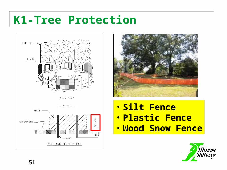
K1-Tree Protection
51
• Silt Fence• Plastic Fence• Wood Snow Fence

Section M-Base Sheets
52

M8 Crash Wall Modifications Median Piers
Crash Wall Height Increased from 4’-6” to 5’-0”.
53

M8 Crash Wall Modifications Shoulder Piers
Crash Wall Height Increased from 4’-6” to 5’-0”.
54

M 19-22 Roadway Typical Sections-Groups
M19-Group A Mainline Roadways
M20-Group BRamp Roadways
M21-Group CDirectional
Ramp Roadways
M22-Group DGutter
Aggregate shoulder(With & without guardrail)
55

M 23-25 Roadway Typical Sections-Groups
M23-Group EMainline & Ramp
Fill & Cut Sections
M24-Group FGutter with
Single Slope Barrier
M25-Group GGutter with Noisewalls
56

Roadway Typical Sections-Groups
M 19-Group A Mainline Roadways
M 22-Group DGutter with
Guardrail
M 23-Group EMainline
Fill Sections
57

M26-Outlet Control Structure-Check Dam Details
58

M27- Overhead Sign Structures Span Type Summary and Total Bill of Material
59

M-28 Overhead Sign Structures Cantilever Type- Steel Summary and Total Bill of Material
60