Fatigue Life Prediction of Prestressed and …...Fatigue Life Prediction of Prestressed and...
8
Fatigue Life Prediction of Prestressed and Reinforced Concrete Railway Bridges R. M. de Souza 1 , R. L. Queiroz 1 , S. L. A. Lobato 1 , R. A. C. Sampaio 1 , A. A. de Azevedo 1,2 1 Graduate Program of Civil Engineering, Federal University of Pará, Belém-Pará, Brazil 2 Development and Logistic Planning, Vale, São Luiz, Maranhão, Brazil. Summary: Evaluation of fatigue damage of the elements of a structure is essential for determining its life expectancy, and is of great interest to both practitioners and researchers. This is especially true for structures subjected to varying loads with great intensity and with a high number of cycles, such as Railway bridges. This paper presents a methodology, and corresponding computer implementation, for estimating fatigue life of reinforced and/or prestressed concrete girders and columns of railway bridges, following the recommendations of CEB-FIP model code 90. Based on the concepts of influence lines according to Müller-Breslau Principle, the developed computer program first determines the variation of the internal forces in a given section of a girder or column, due to the passage of different train types, and considering an appropriate impact coefficient. Starting from the temporal series of the internal forces, another module of the program performs a nonlinear biaxial analysis of the section of interest, using a fiber-section model, and then computes the strain and corresponding stress variations in several components of the section (concrete, reinforcing bars, prestressing cables, etc). As the amplitudes of the stress cycles are not constant, Rainflow algorithm is used to count stress cycles, and appropriate S-N curves for concrete and steel are used to obtain the damage caused by each cycle. Miner rule is then employed to determine the complete damage caused by the entire load block, which corresponds to the passage of a pair of trains (in the loaded and unloaded condition). Depending on the damage caused by each load block, and the number of daily passages, the program is able to compute life expectancy in years. As an application example, the program has been used to evaluate, under current and future traffic conditions, the life expectancy of some structural members of a bridge of Carajás Railway, a heavy haul line located in Brazil. The bridge under study is formed by simply supported prestressed concrete beams with a span length of about 30m, supported on reinforced concrete columns. The obtained results revealed that the fatigue life expectancy for the analyzed columns of this bridge is satisfactory, and that the proposed methodology is appropriate for this type of study. Index Terms: Fatigue Life, Prestressed Concrete, Reinforced Concrete, Railway Bridges. 1. INTRODUCTION One of the main concerns regarding structural integrity of railway bridges is fatigue damage [1, 2, 3, 4, 5, 6] as it can cause the collapse of the structure. This paper presents a methodology, and corresponding computer implementation, for estimating fatigue life of reinforced and/or prestressed concrete girders and columns of railway bridges, following the recommendations of CEB-FIP model code 90 [7]. These recommendations are based on Miner’s Rule [8], and the code proposes appropriate S-N curves for both steel and concrete. As an application example, the developed computer program has been used to evaluate, under current and future traffic conditions, the life expectancy of some structural members of a bridge of Carajás Railway (EFC), a heavy haul line located in the Brazilian Amazon Region, and used for transportation of iron ore.
Transcript of Fatigue Life Prediction of Prestressed and …...Fatigue Life Prediction of Prestressed and...

Fatigue Life Prediction of Prestressed and Reinforced Concrete
Railway Bridges
R. M. de Souza1, R. L. Queiroz1, S. L. A. Lobato1, R. A. C. Sampaio1, A. A. de Azevedo1,2 1 Graduate Program of Civil Engineering, Federal University of Pará, Belém-Pará, Brazil
2 Development and Logistic Planning, Vale, São Luiz, Maranhão, Brazil.
Summary: Evaluation of fatigue damage of the elements of a structure is essential for determining its life expectancy, and is of great interest to both practitioners and researchers. This is especially true for structures subjected to varying loads with great intensity and with a high number of cycles, such as Railway bridges. This paper presents a methodology, and corresponding computer implementation, for estimating fatigue life of reinforced and/or prestressed concrete girders and columns of railway bridges, following the recommendations of CEB-FIP model code 90. Based on the concepts of influence lines according to Müller-Breslau Principle, the developed computer program first determines the variation of the internal forces in a given section of a girder or column, due to the passage of different train types, and considering an appropriate impact coefficient. Starting from the temporal series of the internal forces, another module of the program performs a nonlinear biaxial analysis of the section of interest, using a fiber-section model, and then computes the strain and corresponding stress variations in several components of the section (concrete, reinforcing bars, prestressing cables, etc). As the amplitudes of the stress cycles are not constant, Rainflow algorithm is used to count stress cycles, and appropriate S-N curves for concrete and steel are used to obtain the damage caused by each cycle. Miner rule is then employed to determine the complete damage caused by the entire load block, which corresponds to the passage of a pair of trains (in the loaded and unloaded condition). Depending on the damage caused by each load block, and the number of daily passages, the program is able to compute life expectancy in years. As an application example, the program has been used to evaluate, under current and future traffic conditions, the life expectancy of some structural members of a bridge of Carajás Railway, a heavy haul line located in Brazil. The bridge under study is formed by simply supported prestressed concrete beams with a span length of about 30m, supported on reinforced concrete columns. The obtained results revealed that the fatigue life expectancy for the analyzed columns of this bridge is satisfactory, and that the proposed methodology is appropriate for this type of study.
Index Terms: Fatigue Life, Prestressed Concrete, Reinforced Concrete, Railway Bridges.
1. INTRODUCTION One of the main concerns regarding structural integrity of railway bridges is fatigue damage [1, 2, 3, 4, 5, 6] as it can cause the collapse of the structure. This paper presents a methodology, and corresponding computer implementation, for estimating fatigue life of reinforced and/or prestressed concrete girders and columns of railway bridges, following the recommendations of CEB-FIP model code 90 [7]. These
recommendations are based on Miner’s Rule [8], and the code proposes appropriate S-N curves for both steel and concrete. As an application example, the developed computer program has been used to evaluate, under current and future traffic conditions, the life expectancy of some structural members of a bridge of Carajás Railway (EFC), a heavy haul line located in the Brazilian Amazon Region, and used for transportation of iron ore.
32,25
32,25
31,70
31,70
327,25
32,25
32,2531,70
Elevation View
32,2532,25
31,70
Plan view
São Luís (North)
32,2532,25
71,2031,83 31,83
71,2031,83 31,83
Carajás (south)
5,8
5
13,80 13,80
Abutment P1 P2 P3 P4 P5 P6 P7 P8 Abutment
Figure 1: Plan and elevation views of the bridge over the Mearim River (unit: m).
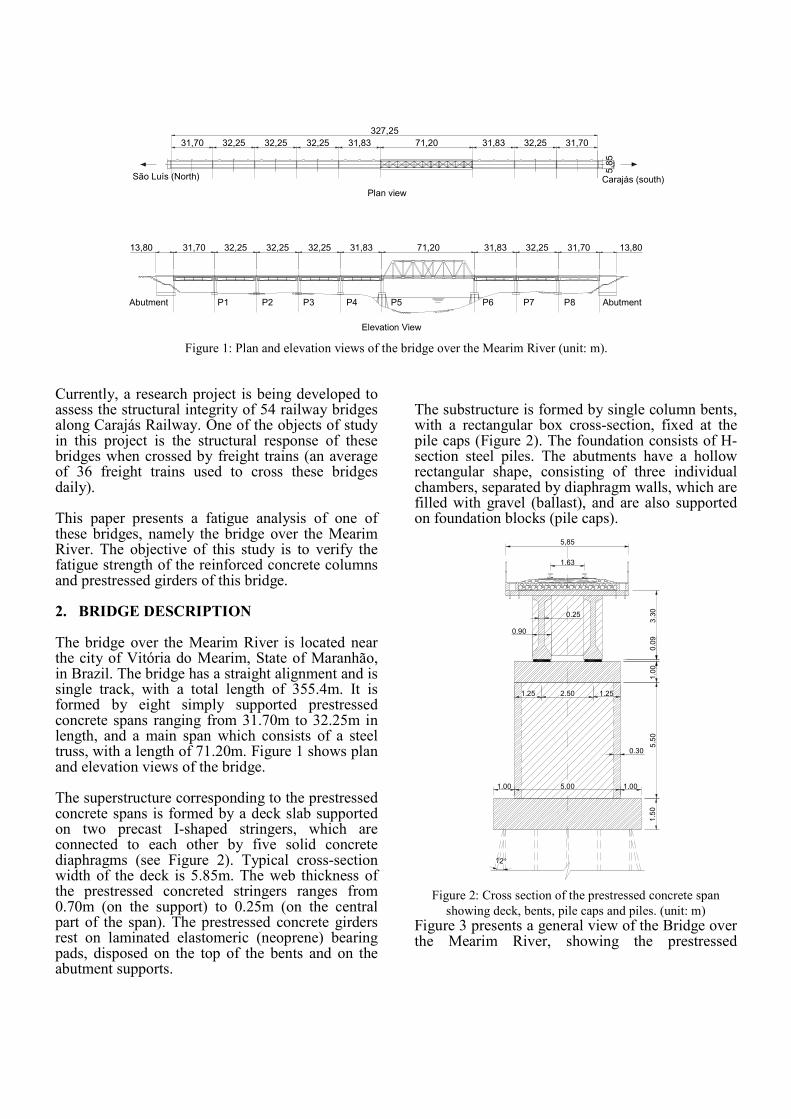
Currently, a research project is being developed to assess the structural integrity of 54 railway bridges along Carajás Railway. One of the objects of study in this project is the structural response of these bridges when crossed by freight trains (an average of 36 freight trains used to cross these bridges daily). This paper presents a fatigue analysis of one of these bridges, namely the bridge over the Mearim River. The objective of this study is to verify the fatigue strength of the reinforced concrete columns and prestressed girders of this bridge. 2. BRIDGE DESCRIPTION The bridge over the Mearim River is located near the city of Vitória do Mearim, State of Maranhão, in Brazil. The bridge has a straight alignment and is single track, with a total length of 355.4m. It is formed by eight simply supported prestressed concrete spans ranging from 31.70m to 32.25m in length, and a main span which consists of a steel truss, with a length of 71.20m. Figure 1 shows plan and elevation views of the bridge. The superstructure corresponding to the prestressed concrete spans is formed by a deck slab supported on two precast I-shaped stringers, which are connected to each other by five solid concrete diaphragms (see Figure 2). Typical cross-section width of the deck is 5.85m. The web thickness of the prestressed concreted stringers ranges from 0.70m (on the support) to 0.25m (on the central part of the span). The prestressed concrete girders rest on laminated elastomeric (neoprene) bearing pads, disposed on the top of the bents and on the abutment supports.
The substructure is formed by single column bents, with a rectangular box cross-section, fixed at the pile caps (Figure 2). The foundation consists of H-section steel piles. The abutments have a hollow rectangular shape, consisting of three individual chambers, separated by diaphragm walls, which are filled with gravel (ballast), and are also supported on foundation blocks (pile caps).
3.3
01.0
05.5
01
.50
1.00 5.00 1.00
1.25 1.25
12°
0.30
1.63
5,85
2.50
0.25
0.90
0.0
9
Figure 2: Cross section of the prestressed concrete span
showing deck, bents, pile caps and piles. (unit: m)
Figure 3 presents a general view of the Bridge over the Mearim River, showing the prestressed

concrete girders, single column bents, and part of the steel truss.
Figure 3: General view of the bridge over the Mearim River
The bridge over the Mearim River was designed in the late 1970s according to Brazilian codes NBR6118 (NB1 1978) [9] and NBR7187 (NB2 1961) [10], for Cooper E-80 loading [11], with appropriate impact. The bridge was constructed in the early 1980s, and since then, the prestressed concrete spans (which are the main object of this study) have shown no significant deterioration, even under the live load demands of current, heavier rail traffic.
3. DESCRIPTION OF TRAINS Carajás Railway is mainly used to transport iron ore. The trains that operate on this railway are hauled by three diesel-electric locomotives (with 300kN per axle) and have 208 freight cars (with 325kN per axle, on loaded condition, and 52.5kN per axle, on unloaded condition). Figure 4 schematically shows typical locomotives and freight cars used on Carajás Railway. The locomotive and freight cars (Figure 4) of current and future trains can be disposed in different sequential arrangements, as follows:
a) Operational train type 1: 2 locomotives, 104 freight cars, 1 locomotive, 104 freight cars;
b) Operational train type 2: 3 locomotives, 208 freight cars;
c) Future train type 1: 2 locomotives, 110 freight cars, 1 locomotive, 110 freight cars, 1 locomotive, 110 freight cars;
d) Future train type 2: 2 locomotives, 220 freight cars, 2 locomotives, 220 freight cars.
4. MONITORING PROGRAM The part of the bridge under study in the present work encompasses the prestressed concrete spans. As the corresponding structural system consists of simply supported beams, of about the same length, two adjacent spans were instrumented and monitored during vehicular traffic. The studied spans were located between columns P6 and P8 (see Figure 1). Although the bridge deck was instrumented, this paper only describes the analysis of column P7.
4.1 Instrumentation
Electrical resistance strain gages were used to capture cross-section deformation of a bridge column. Strain gages for steel (Kyowa, KFG-5-120-C1-11) were installed on four reinforcing bars located in each of the four faces of the column. In addition, two strain gages for concrete (Kyowa, KC-80-120-A1-11) were installed directly on the concrete surface, in the vicinity of the instrumented rebars. This was done in order to compare the results of strains in steel and concrete, and to verify whether it was really necessary to instrument the reinforcing bars. Figure 5 shows the sensor arrangement in this test program.
4.2 Experimental results The columns were monitored during the passage of a loaded and an unloaded train, corresponding to Operational train type 1 (see Figure 6). The strain histories corresponding to the strain gages installed on the reinforcing bars are shown in Figure 7. It should be noted that the maximum strain caused by the moving loads are in the order of
640 10 m/m = 40 strainµ−× .
5. NUMERICAL SIMULATIONS A structural analysis computer program was developed in Matlab, to determine the imposed axial force and bending moment on any given section of the girders and columns, due to the passage of a train.

Figure 4: Typical locomotives and freight cars used on Carajás Railway. (unit: m)
São
Luis
Sid
e
Cara
jás s
ide
Left Side
Right Side
SG2 SG4
Right Side Left sideCarajás side São Luis side
SG6SG1
SG3SG5
1.20 1.20
1.5
5
1.6
3
2.59
2.78
1.5
5
1.5
4
1.5
5
2.50
2.71
Figure 5: Instrumentation plan for the column, with strain gage locations (unit: m). SG1 to SG4 are attached to rebars. SG5 and
SG6 are installed on the concrete surface.
Figure 6: train passing on the bridge.
Figure 7: Strain histories on Column P7.

As the bridge under study is composed of independent simply supported spans, resting on rubber bearings, which can be modeled as simple hinges, it is straight forward to determine the influence lines of any force of interest, using the Müller-Breslau Principle. An alternative solution consists in using the influence line computed using the direct stiffness method or any finite element based computer program, such as SAP2000. 5.1 Numerical model of the structure The structure was modeled with uniaxial elements. The connection between the deck girders and the bridge bents was modeled as represented in Figure
8. In this system, the girders and columns are modeled as beam elements with their reference axis passing through the corresponding center of gravity of the concrete gross cross-section. The beams and columns are connected through rigid links (which represent the rigid joint offsets) pinned at the neoprene bearings (which are represented by simple hinges), as indicated in the figure. The structural system adopted in the present analysis, and the type of loadings accepted by the program, are schematically shown in Figure 9. The model corresponds to two simply supported beams (with short cantilevers), which are adjacent to a common bent. This is a typical configuration for isostatic prestressed concrete bridges.
beam element representing
stringers and deck
frame element
representing a column
rigid link representing
joint offsets
hinges representing
bearings
pile cap
piles
fixed end representing
foundations
Figure 8: Model of the connection between prestressed
girders and bridge bents.
Figure 9: Structural system for computation of internal forces.
The axial force and bending moment influence lines for the column base section were obtained using the Müller-Breslau Principle [12]. To obtain the influence line, the corresponding kinematic link is removed (released) and a unit virtual displacement is imposed at the release. The resulting virtual displacement field is the corresponding influence line [12]. 5.2 Force demand histories Internal force histories were obtained with the methodology proposed above and are presented next. As an illustrative example, Figure 10 and Figure 11 show, respectively, the variation of axial force and bending moment demands at the base of column P7, during the passage of operational train type 1. The variable on the abscissa denotes the position of the first axle of the train with respect to the origin of the structure (which is the left most support of the spans). 5.3 Fiber Section Model To compute strain and stresses over the cross-section, it was analyzed with a fiber-section model, which takes into account the contribution of all materials that form the section, and their corresponding nonlinear constitutive relations. With this model, it is possible to consider concrete cracking and steel yielding. Figure 12 shows the fiber section discretization of a typical column of the bridge. The dimensions of the section and the diameter and positions of the reinforcing bars were obtained from the design plants.

0 500 1000 1500 2000 2500-6000
-5000
-4000
-3000
-2000
-1000
0
1000
Front axle location from left suport(m)
Axia
l F
orc
e(k
N)
Axial Force - column P7 - train type: Operational 1 Loaded
Figure 10: Axial force demand history of column P7.
0 500 1000 1500 2000 2500-4000
-3000
-2000
-1000
0
1000
2000
3000
Front axle location from left suport(m)
Bendin
g M
om
ent
(kN
.m)
Bending moment - column P7 - train type: Operational 1 Loaded
Figure 11: Bending moment demand history of column P7.
Figure 12: Fiber section discretization of column (units: m).
5.4 Strain histories From the theoretical variation of the axial force and bending moment of the column, as a function of
train position, it was possible to determine the theoretical (numerical) strain variations that are supposed to be measured with the installed strain gages. The strain histories were obtained with the fiber section model, and using a Newton-Raphson based algorithm. Figure 13 shows the strain history of two points of the column section: one at the Carajás face and other at the São Luis face (see Figure 5).
Figure 13: strain histories at the faces of the column section.
6. FATIGUE ANALISYS The Brazilian NBR6118 Code [9], and the European CEB-FIP Model Code 90 [7] were employed to estimate fatigue life of the sections under study. CEB-90 presents sequentially three methods for design verification, with an increasing refinement, and, NBR6118 is based on CEB-90. However, for fatigue verification of concrete, NBR6118 only presents the simplest method, which does not allow an estimation of fatigue life. Thus, in the present work, the most refined method of CEB-90 was employed to compute fatigue life expectancy of the structure.
In order to provide a better interpretation of the
strains measured with the strain gages on column
P7, it is interesting to compare these experimental
strains with the theoretical strains presented in
Figure 13. A comparison between these strains is
shown in Figure 14, regarding the period
corresponding to the passage of the locomotives on
the monitored spans.

(a) (b)
Figure 14: Comparison between theoretical and experimental strains, during the passage of a locomotive.
(a) Experimental results. (b) Theoretical results.
As the amplitudes of the stress cycles are not constant in this problem, Rainflow algorithm [14] was used to count the stress cycles, and appropriate S-N curves for concrete and steel are used to obtain the damage caused by each cycle. Miner rule [8] was then employed to determine the complete damage caused by the entire load block, which corresponds to the passage of a pair of trains (in the loaded and unloaded condition). Depending on the damage caused by each load block, and the number of daily passages, the program is able to compute life expectancy in years. To illustrate the procedure of cycle counting, Figure 15 shows a graphical representation of the stress-cycle counting matrix obtained with Rain-Flow algorithm. Thus, with the fatigue analysis procedure described in CEB-90, it was possible to predict fatigue life for each element of the cross-section (concrete and steel), at the most critical points of the section. The results are presented in Table 1, for train type operational 1. To compute fatigue life expectancy in years, from the
fatigue life expectancy in load blocks (pair of loaded
and unloaded trains), it was considered that 18 trains
used to cross the bridge per day, during 365 days per
year. Table 3 summarizes the results presenting
fatigue life expectancy of column P7 for different
trains.
Figure 15: cycle counting matrix for the reinforcing bars,
obtained with Rain-Flow algorithm.
Table 1 – Fatigue analysis of Column P7,Operational train
type 1.
Elemento Damage
Loaded
train
Unloaded
train
Total
(pair)
Rebar SL side 2.68E-17 5.87E-19 2.74E-17
Rebar Carajás side 2.10E-17 1.14E-18 2.21E-17
Concrete SL side 2.86E-34 2.67E-58 2.86E-34
Concrete Caraj. side 3.49E-35 8.11E-53 3.49E-35
cross-section damage 2.74E-17
Life expectancy in blocks (pairs of trains) 3.65E+16
Life expectancy in years 5.56E+12

Table 2 – Fatigue life expectancy of Column P7 for different
trains.
Train type Life Expectancy
In Load Blocks In years*
Operational 1 3.65E+16 5.56E+12
Operational 2 3.66E+16 5.57E+12
Future 1 5.03E+15 7.66E+11
Future 2 5.99E+15 9.12E+11
From Table 2 it can be observed that life expectancy
is very long (practically infinite), as the damage due
to fatigue is small, since the service stress are very
low, both for concrete and steel.
7. CONCLUSIONS
Regarding the strain analysis, it should be observed
that the numerical simulations are in close agreement
with the experimental results (see Figure 14). It can
be concluded that the influence of the sequential
arrangement (disposition of locomotives and freight
cars) has a very small effect on fatigue life
expectancy. It can also be concluded that, although
the increase in per-axle load is considerable,
comparing the current and future trains, fatigue life
expectancy for current and future trains are very high
(practically infinite).
8. ACKNOWLEDGMENTS
This work was developed in the context of the
Research Project entitled “Development of a
methodoly for assessing the structural integrity of
railway bridges” proposed by UFPA (Federal
University of Pará, Brazil) and financed by VALE
mining company. The writers gratefully acknowledge
the corresponding funding support provided by
VALE. The writers are also grateful to Lourival S. F.
Neto who helped conceiving this research proposal.
The field studies on the Mearim River Bridge
presented in this paper were performed by a joint
UFPA/VALE research team. The writers wish to
acknowledge all the field team members Francisco
Vicente. S. Neto, Paulo Athayde, Sandro D. R.
Amador, and Lílian Danyelle A. de Oliveira, for their
cooperation and help during the tests.
9. REFERENCES
[1] Köröndi, L.; Szittner, A.; Kálló, M.; Kristóf, L.
Determination of Fatigue Safety and Remaining Fatigue Life
on a Riveted Railway Bridge by Measurement, J. Construct.
Steel Res. 46, 1-3, (1998), 430.
[2] Li, Z.X.; Chan, T.H.T; Ko, J.M. Fatigue analysis and life
prediction of bridges with structural health monitoring data
— Part I: methodology and strategy. International Journal of
Fatigue 23 (2001) 45-53.
[3] Li, Z.X.; Chan, T.H.T; Zheng, R. Statistical analysis of
online strain response and its application in fatigue
assessment of a long-span steel bridge. Engineering
Structures 25 (2003) 1731-1741.
[4] Chan, T.H.T; Li, Z.X.; Ko, J.M. Fatigue analysis and life
prediction of bridges with structural health monitoring data
— Part II: application. International Journal of Fatigue, 23
(2001) 55-64.
[5] Kim, S-H.; Lee, S-W.; Mha, H-S. Fatigue reliability
assessment of an existing steel railroad bridge. Engineering
Structures 23 (2001) 1203-1211.
[6] Frýba, L.; Gajdos, L. Fatigue properties of orthotropic
decks on railway bridges, Engineering Structures 21 (1999)
632-652.
[7] CEB-FIP Model Code 90. Design of concrete structures.
Comité Euro-International du Béton (CEB) and the
Fédération International de la Précontrainte. 1990.
[8] Miner, M. A. Cumulative damage in fatigue. Journal of
Applied Mechanics 1945;67:A159–64.
[9] NB1 – NBR6118. Design and Execution of Reinforced
Concrete Structures (in Portuguese). Brazilian Technical
Standards Association, ABNT, Rio de Janeiro, Brazil. 1978.
[10] NB2 – NBR7187. Design and Execution of Reinforced
Concrete Bridges (in Portuguese). Brazilian Technical
Standards Association, ABNT, Rio de Janeiro, Brazil. 1961.
[11] AREMA. Manual for Railway Engineering. The
American Railway Engineering and Maintenance-of-Way
Association. 2007.
[12] Malek, A. M.; Jáuregui, D. V. Computer-Aided
Graphical Analysis of Bridges under Vehicular Loading.”
ASCE Journal of Bridge Engineering, Vol. 6, No. 3, pp. 207-
212, 2001.
[13] NBR 6118. Design of Concrete Structures – Procedure
(in Portuguese). Brazilian Technical Standards Association,
ABNT, Rio de Janeiro, Brazil. 2003.
[14] ASTM E-1049-85. Standard Practices for Cycle
Counting in Fatigue Analysis. American Society for Testing
and Materials. 2005.