UPRR Fatigue Conference Studies of Passenger Work Rest Schedules
Corresponding author. Tel./fax: +91 9677266992 © 2015 JMSSE All rights reserved
E-mail address: [email protected]
Journal of Materials Science & Surface Engineering Vol. 3 (1), 2015, pp 171-176
Contents lists available at http://www.jmsse.org/
Journal of Materials Science & Surface Engineering
Fatigue Life Prediction and Durability test of passenger car Rheocast Aluminium Steering
Knuckle
Siddesh Gowda KG1, Avjot Singh Ghai
2, Sagar Polisetti
1, Shashank Tiwari1 and Ashok B
2 1Mahindra Research Valley, Mahindra & Mahindra Ltd., Chennai - 603204, India. 2Vellore Institute of Technology, Vellore - 632014, India
Article history Abstract Received: 02-May-2015 Revised: 10-June-2015
Available online: 01 July, 2015
Keywords:
Rheocasting,
Aluminium knuckle,
Strain gauging,
Road Load Data
Acquisition(RLDA),
Fatigue life prediction,
Durability lab test,
Block program generation
Ride and Handling of any passenger car is one of the most selling parameter in today’s automotive industry. Keeping the un-sprung mass as low as possible without compromising the required strength and stiffness is one of the most challenging problems today as the un-sprung mass directly effects the ride and handling of the car. Steering knuckle which is one of the most critical parts of the un-sprung system of a car significantly contributes to the un-sprung mass of a car and thus forms an important opportunity to reduce its mass. For this, an aluminium knuckle developed by a recent manufacturing technique called rheocasting is chosen. Very limited data is available on fatigue strength and durability of Rheocast aluminium knuckle as on today. In this paper, an attempt is made to calculate fatigue life using measured strain data through RLDA and test data for the durability strength of a passenger car's Rheocast Aluminium knuckle. Strain and Stress based Fatigue life prediction techniques are then applied with different mean stress correction schemes to calculate life of the knuckle using measured strain data. Rheocast aluminium knuckle was tested using servo hydraulic actuator for its static and durability strength. Strain comparison was made between track and lab and established rig level durability test. Predicted life from different models are compared with actual failure cycles from physical test to establish the prediction model suitable for knuckle life calculation.
The work had been presented at an international conference Fatigue Durability India 2015, 28-30th May 2015, JN TATA AUDITORIUM, Indian Institute of Science, Bangalore. © 2015 JMSSE All rights reserved
Introduction
Since 1990, the steady increase in the mass of the typical family
vehicles due to safety and luxury has challenged the automakers
ability to comply with the fuel efficiency standards, other than
causing significant mass problems. The strive for original
equipment manufacturer (OEMs) to comply with current and
future fuel efficiency standards and emissions legislation has been
the critical path for the reversal of this mass spiral. The use of
lighter components in the suspension system (un-sprung mass)
helps to improve ride quality and handling, as well.1-2
In today's automobile, the mass of the un-sprung components is
normally 13 to 15 percent of the vehicle curb mass. In the case of a
1750 kilograms vehicle, un-sprung mass may be as high as
250kilograms. A 250 kilograms mass reacting directly to roadway
irregularities at high speeds can generate significant vertical
acceleration forces3. These forces degrade the ride, and they also
have a detrimental effect on handling. 2
As the knuckle has a greater mass compared to the other parts, it
has a greater impact in reducing the overall mass of the un-sprung
mass. Hence, this study aims at reducing the mass of the steering
knuckle and validating it through its durability testing.
Presently, most of the passenger car manufacturers use either
steel forged or ductile iron casted knuckle, which are bulky and
heavy.1 Aluminium alloys were found to be a feasible alternative
option because of its high strength to weight ratio, corrosion
resistance, ductile nature, mainly light weight properties and
economic feasibility.
Experimental
Material Properties
Aluminium Alloy A356 was used to manufacture the steering
knuckle. The chemical composition of the material used in this
study is given in table 1. The typical mechanical properties of Al
A356-T6 is presented in table 2.
Table 1: Chemical composition of Aluminium A356-T6
Cu % Mg % Si % Ti % Mn % Zn % Fe % Others % Al %
0.2 0.2 -
0.4
6.5 -
7.5 0.25 0.1 0.1 0.2 0.15
91.1 –
92.3
Table 2: Tensile properties of Al A356-T68
Tensile Strength (MPa) Elongation %
A356-T6 250 8.6 - 13.2
Manufacturing Process involved
The manufacturing process chosen for the development of the
steering knuckle is Rheocasting for its advantages over the
conventional methods discussed later.
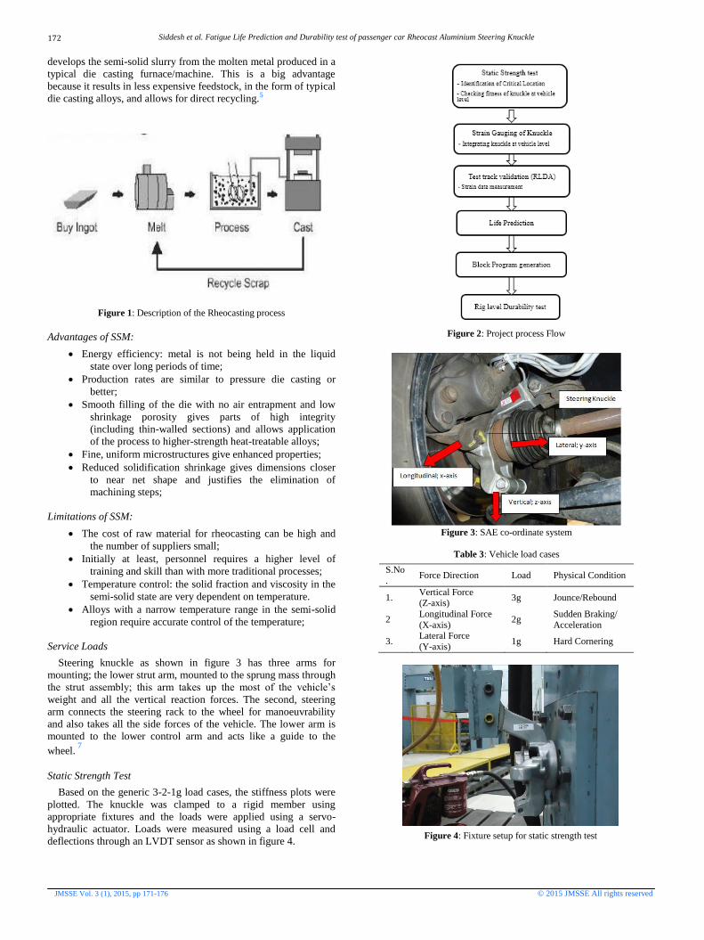
Rheocasting is a form of Semi solid metal casting (SSM)
technology as shown in figure 1. SSM is done at a temperature that
puts the metal between its liquidus and solidus temperature.
Ideally, the metal should be 30 to 65% solid. The metal must have
a low viscosity to be usable. The temperature range at the slurry
state required for aluminium alloys is 5–10 °C. Rheocasting
Siddesh et al. Fatigue Life Prediction and Durability test of passenger car Rheocast Aluminium Steering Knuckle
JMSSE Vol. 3 (1), 2015, pp 171-176 © 2015 JMSSE All rights reserved
develops the semi-solid slurry from the molten metal produced in a
typical die casting furnace/machine. This is a big advantage
because it results in less expensive feedstock, in the form of typical
die casting alloys, and allows for direct recycling.5
Figure 1: Description of the Rheocasting process
Advantages of SSM:
Energy efficiency: metal is not being held in the liquid
state over long periods of time;
Production rates are similar to pressure die casting or
better;
Smooth filling of the die with no air entrapment and low
shrinkage porosity gives parts of high integrity
(including thin-walled sections) and allows application
of the process to higher-strength heat-treatable alloys;
Fine, uniform microstructures give enhanced properties;
Reduced solidification shrinkage gives dimensions closer
to near net shape and justifies the elimination of
machining steps;
Limitations of SSM:
The cost of raw material for rheocasting can be high and
the number of suppliers small;
Initially at least, personnel requires a higher level of
training and skill than with more traditional processes;
Temperature control: the solid fraction and viscosity in the
semi-solid state are very dependent on temperature.
Alloys with a narrow temperature range in the semi-solid
region require accurate control of the temperature;
Service Loads
Steering knuckle as shown in figure 3 has three arms for
mounting; the lower strut arm, mounted to the sprung mass through
the strut assembly; this arm takes up the most of the vehicle’s
weight and all the vertical reaction forces. The second, steering
arm connects the steering rack to the wheel for manoeuvrability
and also takes all the side forces of the vehicle. The lower arm is
mounted to the lower control arm and acts like a guide to the
wheel. 7
Static Strength Test
Based on the generic 3-2-1g load cases, the stiffness plots were
plotted. The knuckle was clamped to a rigid member using
appropriate fixtures and the loads were applied using a servo-
hydraulic actuator. Loads were measured using a load cell and
deflections through an LVDT sensor as shown in figure 4.
Figure 2: Project process Flow
Figure 3: SAE co-ordinate system
Table 3: Vehicle load cases
S.No
. Force Direction Load Physical Condition
1. Vertical Force (Z-axis)
3g Jounce/Rebound
2 Longitudinal Force
(X-axis) 2g
Sudden Braking/
Acceleration
3. Lateral Force
(Y-axis) 1g Hard Cornering
Figure 4: Fixture setup for static strength test
172
Siddesh et al. Fatigue Life Prediction and Durability test of passenger car Rheocast Aluminium Steering Knuckle
JMSSE Vol. 3 (1), 2015, pp 171-176 © 2015 JMSSE All rights reserved
Figure 5: Stiffness plot of steering knuckle
The stiffness plot as shown in figure 5 determines the behaviour
of the component while loading as compared to the standard
specimen of the same material. Test results showed that the
ultimate strength of the knuckle is beyond the maximum service
loads acting (as per generic 3-2-1g load cases). Also, the critical
zones as shown in figure 6 were identified which were used in the
later part of the project.
Figure 6: Fracture location of the knuckle
Results and Discussion
Strain gauging
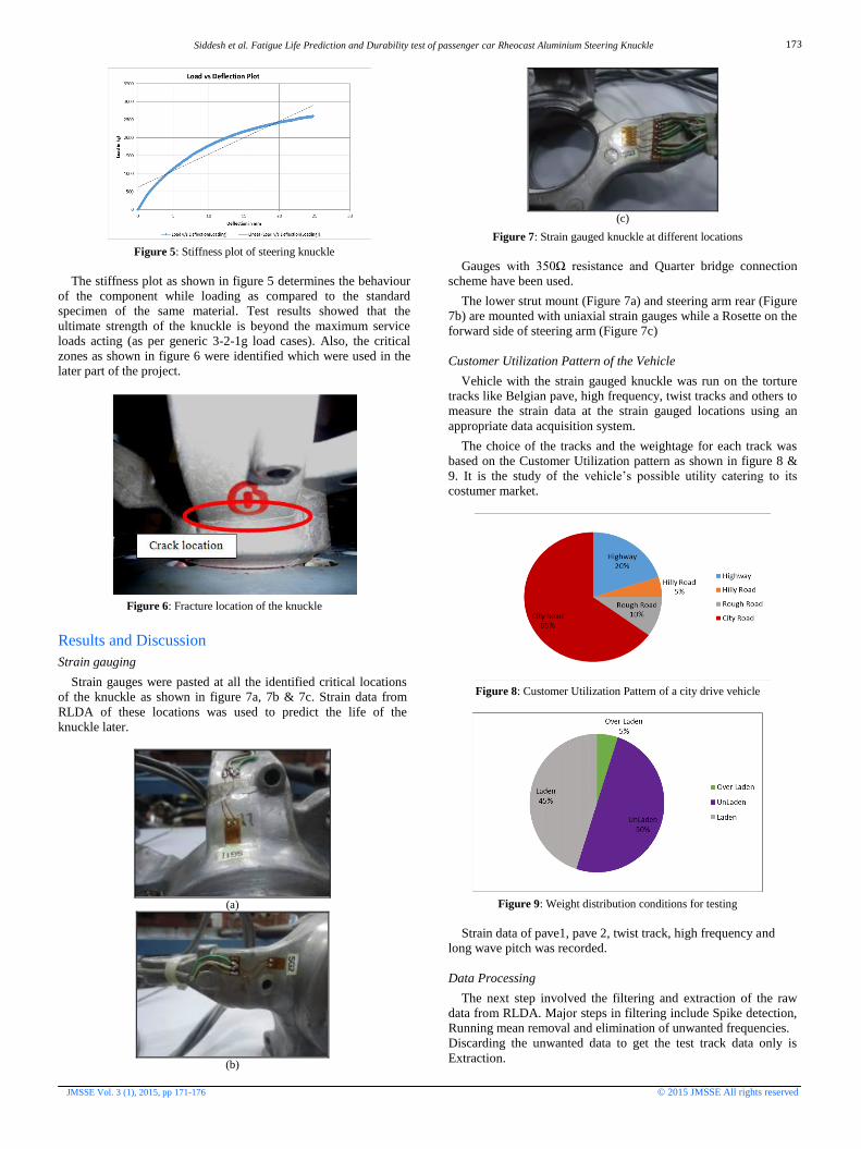
Strain gauges were pasted at all the identified critical locations
of the knuckle as shown in figure 7a, 7b & 7c. Strain data from
RLDA of these locations was used to predict the life of the
knuckle later.
(a)
(b)
(c)
Figure 7: Strain gauged knuckle at different locations
Gauges with 350Ω resistance and Quarter bridge connection
scheme have been used.
The lower strut mount (Figure 7a) and steering arm rear (Figure
7b) are mounted with uniaxial strain gauges while a Rosette on the
forward side of steering arm (Figure 7c)
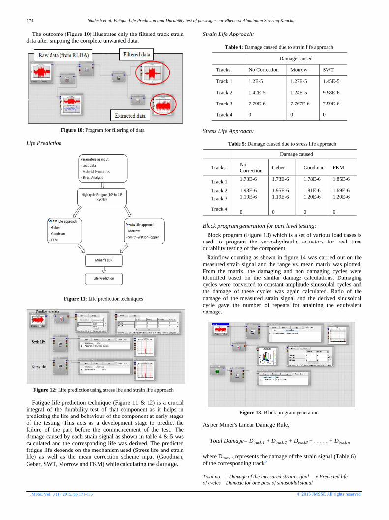
Customer Utilization Pattern of the Vehicle
Vehicle with the strain gauged knuckle was run on the torture
tracks like Belgian pave, high frequency, twist tracks and others to
measure the strain data at the strain gauged locations using an
appropriate data acquisition system.
The choice of the tracks and the weightage for each track was
based on the Customer Utilization pattern as shown in figure 8 &
9. It is the study of the vehicle’s possible utility catering to its
costumer market.
Figure 8: Customer Utilization Pattern of a city drive vehicle
Figure 9: Weight distribution conditions for testing
Strain data of pave1, pave 2, twist track, high frequency and
long wave pitch was recorded.
Data Processing
The next step involved the filtering and extraction of the raw
data from RLDA. Major steps in filtering include Spike detection,
Running mean removal and elimination of unwanted frequencies.
Discarding the unwanted data to get the test track data only is
Extraction.
173
Siddesh et al. Fatigue Life Prediction and Durability test of passenger car Rheocast Aluminium Steering Knuckle
JMSSE Vol. 3 (1), 2015, pp 171-176 © 2015 JMSSE All rights reserved
The outcome (Figure 10) illustrates only the filtered track strain
data after snipping the complete unwanted data.
Figure 10: Program for filtering of data
Life Prediction
Figure 11: Life prediction techniques
Figure 12: Life prediction using stress life and strain life approach
Fatigue life prediction technique (Figure 11 & 12) is a crucial
integral of the durability test of that component as it helps in
predicting the life and behaviour of the component at early stages
of the testing. This acts as a development stage to predict the
failure of the part before the commencement of the test. The
damage caused by each strain signal as shown in table 4 & 5 was
calculated and the corresponding life was derived. The predicted
fatigue life depends on the mechanism used (Stress life and strain
life) as well as the mean correction scheme input (Goodman,
Geber, SWT, Morrow and FKM) while calculating the damage.
Strain Life Approach:
Table 4: Damage caused due to strain life approach
Damage caused
Tracks No Correction Morrow SWT
Track 1 1.2E-5 1.27E-5 1.45E-5
Track 2 1.42E-5 1.24E-5 9.98E-6
Track 3 7.79E-6 7.767E-6 7.99E-6
Track 4 0 0 0
Stress Life Approach:
Table 5: Damage caused due to stress life approach
Damage caused
Tracks No Correction
Geber Goodman FKM
Track 1 1.73E-6 1.73E-6 1.78E-6 1.85E-6
Track 2 1.93E-6 1.95E-6 1.81E-6 1.69E-6
Track 3 1.19E-6 1.19E-6 1.20E-6 1.20E-6
Track 4
0
0
0
0
Block program generation for part level testing:
Block program (Figure 13) which is a set of various load cases is
used to program the servo-hydraulic actuators for real time
durability testing of the component
Rainflow counting as shown in figure 14 was carried out on the
measured strain signal and the range vs. mean matrix was plotted.
From the matrix, the damaging and non damaging cycles were
identified based on the similar damage calculations. Damaging
cycles were converted to constant amplitude sinusoidal cycles and
the damage of these cycles was again calculated. Ratio of the
damage of the measured strain signal and the derived sinusoidal
cycle gave the number of repeats for attaining the equivalent
damage.
Figure 13: Block program generation
As per Miner's Linear Damage Rule,
Total Damage= Dtrack 1 + Dtrack 2 + Dtrack3 + . . . . . + Dtrack n
where Dtrack n represents the damage of the strain signal (Table 6)
of the corresponding track6
Total no. = Damage of the measured strain signal x Predicted life
of cycles Damage for one pass of sinusoidal signal
174
Siddesh et al. Fatigue Life Prediction and Durability test of passenger car Rheocast Aluminium Steering Knuckle
JMSSE Vol. 3 (1), 2015, pp 171-176 © 2015 JMSSE All rights reserved
Figure 14: Rainflow counting of input strain data
Table 6: Damaging strain values
Track Range (µe) Mean (µe)
Track 1 1084 6
1228 6
Track 2 1054 -91
1195 -91
Track 3 1109 19
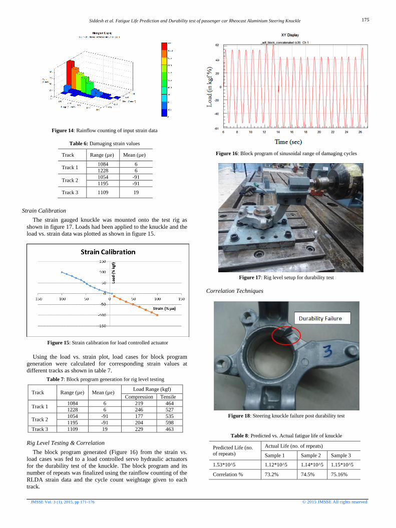
Strain Calibration
The strain gauged knuckle was mounted onto the test rig as
shown in figure 17. Loads had been applied to the knuckle and the
load vs. strain data was plotted as shown in figure 15.
Figure 15: Strain calibration for load controlled actuator
Using the load vs. strain plot, load cases for block program
generation were calculated for corresponding strain values at
different tracks as shown in table 7.
Table 7: Block program generation for rig level testing
Track Range (µe) Mean (µe) Load Range (kgf)
Compression Tensile
Track 1 1084 6 219 464
1228 6 246 527
Track 2 1054 -91 177 535
1195 -91 204 598
Track 3 1109 19 229 463
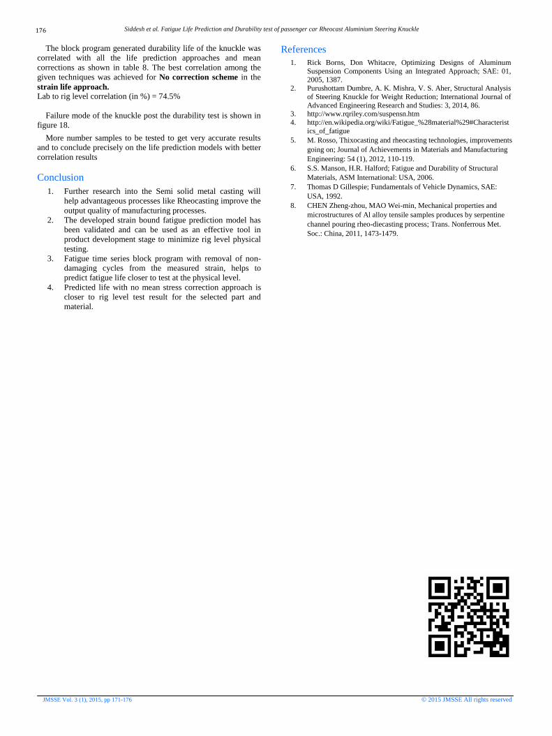
Rig Level Testing & Correlation
The block program generated (Figure 16) from the strain vs.
load cases was fed to a load controlled servo hydraulic actuators
for the durability test of the knuckle. The block program and its
number of repeats was finalized using the rainflow counting of the
RLDA strain data and the cycle count weightage given to each
track.
Figure 16: Block program of sinusoidal range of damaging cycles
Figure 17: Rig level setup for durability test
Correlation Techniques
Figure 18: Steering knuckle failure post durability test
Table 8: Predicted vs. Actual fatigue life of knuckle
Predicted Life (no. of repeats)
Actual Life (no. of repeats)
Sample 1 Sample 2 Sample 3
1.53*10^5 1.12*10^5 1.14*10^5 1.15*10^5
Correlation % 73.2% 74.5% 75.16%
175
Siddesh et al. Fatigue Life Prediction and Durability test of passenger car Rheocast Aluminium Steering Knuckle
JMSSE Vol. 3 (1), 2015, pp 171-176 © 2015 JMSSE All rights reserved
The block program generated durability life of the knuckle was
correlated with all the life prediction approaches and mean
corrections as shown in table 8. The best correlation among the
given techniques was achieved for No correction scheme in the
strain life approach. Lab to rig level correlation (in %) = 74.5%
Failure mode of the knuckle post the durability test is shown in
figure 18.
More number samples to be tested to get very accurate results
and to conclude precisely on the life prediction models with better
correlation results
Conclusion
1. Further research into the Semi solid metal casting will
help advantageous processes like Rheocasting improve the
output quality of manufacturing processes.
2. The developed strain bound fatigue prediction model has
been validated and can be used as an effective tool in
product development stage to minimize rig level physical
testing.
3. Fatigue time series block program with removal of non-
damaging cycles from the measured strain, helps to
predict fatigue life closer to test at the physical level.
4. Predicted life with no mean stress correction approach is
closer to rig level test result for the selected part and
material.
References
1. Rick Borns, Don Whitacre, Optimizing Designs of Aluminum
Suspension Components Using an Integrated Approach; SAE: 01,
2005, 1387. 2. Purushottam Dumbre, A. K. Mishra, V. S. Aher, Structural Analysis
of Steering Knuckle for Weight Reduction; International Journal of
Advanced Engineering Research and Studies: 3, 2014, 86. 3. http://www.rqriley.com/suspensn.htm
4. http://en.wikipedia.org/wiki/Fatigue_%28material%29#Characterist
ics_of_fatigue
5. M. Rosso, Thixocasting and rheocasting technologies, improvements
going on; Journal of Achievements in Materials and Manufacturing
Engineering: 54 (1), 2012, 110-119.
6. S.S. Manson, H.R. Halford; Fatigue and Durability of Structural
Materials, ASM International: USA, 2006.
7. Thomas D Gillespie; Fundamentals of Vehicle Dynamics, SAE:
USA, 1992.
8. CHEN Zheng-zhou, MAO Wei-min, Mechanical properties and
microstructures of Al alloy tensile samples produces by serpentine
channel pouring rheo-diecasting process; Trans. Nonferrous Met.
Soc.: China, 2011, 1473-1479.
176