Integrated Durability Analysis Using ANSYS, ADAMS and Finite Element ...€¦ · Integrated...
25
Integrated Durability Analysis Using ANSYS, ADAMS and Finite Element Fatigue Terrance W. Ewanochko, P.Eng. Rotary Cutter Division, John Deere Welland Works, Welland, Ontario, Canada David Nelson, P.Eng. Martin Esaki, P.Eng. Mechanical Dynamics Ltd., Toronto, Ontario, Canada Eric Pesheck Mechanical Dynamics Inc., Ann Arbor, Michigan, USA Abstract In the competitive economic environment that now exists in practically every segment of mechanical design, the value of assessing the durability of mechanical components as early in the design cycle as possible is obvious. This paper describes an example of an integrated durability analysis process performed on a rotary cutter developed by John Deere, Welland Works using CAE tools exclusively. The Pro/Engineer solid geometry of the cutter was used to generate both a basic ADAMS model (using the embedded product MECHANISM/Pro) and finite element meshes for the flexible components (using Pro/MECHANICA). The flexible bodies were generated using the finite element program ANSYS and then imported into the ADAMS model and their flexibility accounted for in the dynamic simulation of the cutter. The simulation mimicked a rotating drum test that is used in the development of new cutter systems. Embedding finite element representations of critical components within the ADAMS model, offers the advantage of being able to recover the stress/time histories at every node in the finite element model for the entire simulation. This would be analogous to having a virtual strain gauge at every node in the finite element model during the simulation. With the stress/time histories available, FE-Fatigue can be used to perform the durability analysis and the resulting damage and life predictions imported into ANSYS for post processing. This approach successfully predicts crack locations in a physical prototype, thereby validating the analysis procedure Introduction One of the world's oldest and most respected enterprises, Deere & Company creates smart innovations in the form of advanced machines, services, and concepts, for customers on farmsites, worksites, and homesites worldwide. John Deere (JD) is continuously improving the design and manufacturing process by the increasing use of CAE tools. Mechanical Dynamics Ltd. (MDL) is currently assisting the rotary cutter engineering group to implement an integrated virtual durability analysis technique on the new product development process. The description of the work performed on the 15 ft and 20 ft Flex-Wing rotary cutter series follows. The Flex-Wing cutter assembly consists of three articulated sections (center and wings), which are equipped with a rotating cutting blade set and support wheels as shown in Figure 1. The cutter is towed by a tractor, which also provides the mechanical (PTO) and the hydraulic power necessary for the operation. The PTO drives the rotating cutters and the hydraulic line drives the actuator cylinders that are used to control the cutter height and wing lift.
Transcript of Integrated Durability Analysis Using ANSYS, ADAMS and Finite Element ...€¦ · Integrated...

Integrated Durability Analysis Using ANSYS, ADAMS and Finite Element Fatigue
Terrance W. Ewanochko, P.Eng. Rotary Cutter Division, John Deere Welland Works, Welland, Ontario, Canada
David Nelson, P.Eng. Martin Esaki, P.Eng.
Mechanical Dynamics Ltd., Toronto, Ontario, Canada Eric Pesheck
Mechanical Dynamics Inc., Ann Arbor, Michigan, USA
Abstract In the competitive economic environment that now exists in practically every segment of mechanical design, the value of assessing the durability of mechanical components as early in the design cycle as possible is obvious. This paper describes an example of an integrated durability analysis process performed on a rotary cutter developed by John Deere, Welland Works using CAE tools exclusively.
The Pro/Engineer solid geometry of the cutter was used to generate both a basic ADAMS model (using the embedded product MECHANISM/Pro) and finite element meshes for the flexible components (using Pro/MECHANICA). The flexible bodies were generated using the finite element program ANSYS and then imported into the ADAMS model and their flexibility accounted for in the dynamic simulation of the cutter. The simulation mimicked a rotating drum test that is used in the development of new cutter systems. Embedding finite element representations of critical components within the ADAMS model, offers the advantage of being able to recover the stress/time histories at every node in the finite element model for the entire simulation. This would be analogous to having a virtual strain gauge at every node in the finite element model during the simulation. With the stress/time histories available, FE-Fatigue can be used to perform the durability analysis and the resulting damage and life predictions imported into ANSYS for post processing.
This approach successfully predicts crack locations in a physical prototype, thereby validating the analysis procedure
Introduction One of the world's oldest and most respected enterprises, Deere & Company creates smart innovations in the form of advanced machines, services, and concepts, for customers on farmsites, worksites, and homesites worldwide. John Deere (JD) is continuously improving the design and manufacturing process by the increasing use of CAE tools. Mechanical Dynamics Ltd. (MDL) is currently assisting the rotary cutter engineering group to implement an integrated virtual durability analysis technique on the new product development process. The description of the work performed on the 15 ft and 20 ft Flex-Wing rotary cutter series follows.
The Flex-Wing cutter assembly consists of three articulated sections (center and wings), which are equipped with a rotating cutting blade set and support wheels as shown in Figure 1. The cutter is towed by a tractor, which also provides the mechanical (PTO) and the hydraulic power necessary for the operation. The PTO drives the rotating cutters and the hydraulic line drives the actuator cylinders that are used to control the cutter height and wing lift.
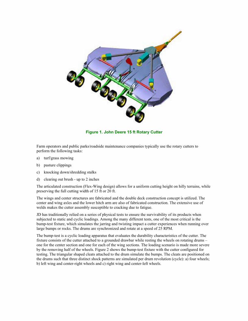
Figure 1. John Deere 15 ft Rotary Cutter
Farm operators and public parks/roadside maintenance companies typically use the rotary cutters to perform the following tasks:
a) turf/grass mowing
b) pasture clippings
c) knocking down/shredding stalks
d) clearing out brush - up to 2 inches
The articulated construction (Flex-Wing design) allows for a uniform cutting height on hilly terrains, while preserving the full cutting width of 15 ft or 20 ft.
The wings and center structures are fabricated and the double deck construction concept is utilized. The center and wing axles and the lower hitch arm are also of fabricated construction. The extensive use of welds makes the cutter assembly susceptible to cracking due to fatigue.
JD has traditionally relied on a series of physical tests to ensure the survivability of its products when subjected to static and cyclic loadings. Among the many different tests, one of the most critical is the bump-test fixture, which simulates the jarring and twisting impact a cutter experiences when running over large bumps or rocks. The drums are synchronized and rotate at a speed of 25 RPM.
The bump-test is a cyclic loading apparatus that evaluates the durability characteristics of the cutter. The fixture consists of the cutter attached to a grounded drawbar while resting the wheels on rotating drums – one for the center section and one for each of the wing sections. The loading scenario is made more severe by the removing half of the wheels. Figure 2 shows the bump-test fixture with the cutter configured for testing. The triangular shaped cleats attached to the drum simulate the bumps. The cleats are positioned on the drums such that three distinct shock patterns are simulated per drum revolution (cycle): a) four wheels; b) left wing and center-right wheels and c) right wing and center-left wheels.

Figure 2. Bump-test fixture (view from below)
The present paper describes the CAE-based durability analysis that is being implemented and developed at JD, rotary cutter division, to predict the fatigue damage corresponding to the bump-test.
The dynamic simulation of the rotary cutter was performed using ADAMS, the leading dynamic systems simulation code. Flexible body representation was included for the main structural members using ANSYS Finite Element Models. The final durability post-processing analysis was performed using the program FE-Fatigue.
Simulated Durability Test General The flowchart in Figure 3 shows the integrated CAE procedure that is used to perform the durability analysis for the rotary cutter. This seamless integration between the CAE applications (Pro/ENGINEER, ADAMS, ANSYS and FE-Fatigue) was made possible by their cooperation and consistent efforts to establish common interface communications channels. The analysis starts with the cutter Pro/E assembly model, which contains the geometry and mass property definitions for all the constituent parts.
Figure 3. Integrated Durability Analysis
The dynamics of the bump-test simulation is performed using the multi-purpose mechanical systems simulation (MSS) package ADAMS. The ADAMS model is generated from the Pro/E model using the interface application MECHANISM/Pro.
The flexibility characteristics of the structural parts are incorporated into the ADAMS model using a modal formulation based upon component mode synthesis. Basically, this method represents the part’s flexibility using a modal basis, which is optimized to account for constraint and force locations. The mode shape displacements and stresses are calculated using the finite element program ANSYS/Multiphysics, rev. 5.7.
The program FE-Fatigue combines the modal coordinate time history information generated by ADAMS for the simulated test, the material fatigue strength characteristics and the modal stress characteristics to generate the predicted life distribution in the part.
The details of each analysis procedure step are explained below.

ADAMS Rotary Cutter Model
Rigid Bodies Initially the basic ADAMS model is generated in the Pro/ENGINEER environment using the ADAMS embedded product MECHANISM/Pro. This model contains all the ADAMS moving part definitions with geometry and mass property characteristics. Interface reference-markers are also generated by temporarily setting up simple joints (e.g. REVOLUTE). This initial model is then transferred to ADAMS/View environment for completion and simulation. The model is finalized with all the required features such as contacts, bushings, motions, couplers and primitive joints and solved for the bump-test using ADAMS/Solver. The parts are, at this stage, rigid bodies.
The rigid bodies model is used to perform the initial debugging, modeling concept testing and selection of suitable integration/solution parameters. Rigid body models run significantly faster than the counterpart models containing flexible bodies, thus allowing faster test runs. Once the simulation robustness is achieved and the initial checks are completed with the rigid bodies model the structural parts are replaced one at a time by their flexible counterparts.
Flexible Bodies For the components of the cutter that were identified as candidates to be modeled as flexible components in ADAMS, the ADAMS/Flex add-on module is used to generate the flex body part representations from the modal neutral files. The flex body modal neutral files (MNF file), which contain the modal mass, stiffness, and deflection characteristics, are obtained using the finite element (FE) method. The general-purpose FE program, ANSYS/Multiphysics rev. 5.7, is used to generate these files. The user runs a macro called “ADAMS” with an argument that represents the number of free-free normal modes the user would like to carry into the ADAMS simulation. The macro automatically generates an MNF file. All the flexible parts are created with 20 free-free requested modes, as well as six “interface modes” for each attachment node in the flexible body.
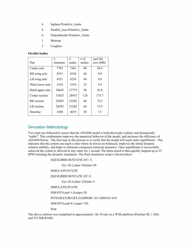
A custom damping strategy is applied with a damping ratio of 10% assigned to modal frequencies less than 200 Hz, a damping ratio of 75% to frequencies between 200 and 500 Hz, and frequencies greater than 500 Hz were critically damped. Table - Flexible bodies lists all the rotary cutter flexible body parts and FE mesh size information. The high frequency modes are dampened to avoid possible highly transient response in the solution, while preserving the high order deformation capability for the flexible part. The solution time can be significantly increased by the presence of high frequency contents in the response. The model correlated well with test data for the chosen damping coefficients.
The FE meshes for the rotary cutter structural members/sub-assemblies are generated using the Pro/MECHANICA module in Pro/Engineer and then exported in ANSYS format. The welded plate construction of the cutter components are particularly well suited to take advantage of the abilities of this module to handle the mid plane compression as well as the very useful “End Weld” and “Perimeter Weld” features. These make the construction of a shell element finite element model much easier and faster in this module than in the more traditional pre/post processing environments.
The ADAMS flexible body model inventory for the 15 ft rotary cutter is listed below:
558 Gruebler Count
113 Moving Parts (not including ground and including 62 massless dummy parts)
9 Flexible_Bodies
9 Revolute Joints
10 Spherical Joints
93 Fixed Joints
6 Inline Primitive_Joints
6 Inplane Primitive_Joints
6 Parallel_axes Primitive_Joints
6 Perpendicular Primitive_Joints
1 Motions
2 Couplers
Flexible bodies
Part
# elements
# nodes
# of modes
mnf file size (MB)
Center axle 7783 7441 80 28.4
RH wing axle 4351 4236 44 9.0
LH wing axle 4351 4236 44 9.0
Hitch lower arm 2310 2510 32 3.9
Hitch upper arm 30645 37775 50 91.6
Center section 33025 28953 128 175.7
RH section 24593 22282 68 72.5
LH section 24593 22282 68 72.5
Drawbar 3308 4019 38 7.5
Simulation Methodology Two steps are followed to assure that the ADAMS model is both physically realistic and dynamically “stable”. This combination improves the numerical behavior of the model, and increases the efficiency of ADAMS/Solver. The first step in this process is to verify that the model will reach static equilibrium. This indicates that the system can reach a state where its forces are balanced, improves the initial dynamic solution stability, and helps to eliminate extraneous transient dynamics. Once equilibrium is successfully achieved the system is allowed to stay static for 1 second. The drum speed is then quickly stepped up to 25 RPM initiating the dynamic simulation. The final simulation script is shown below:
EQUILIBRIUM/STATIC,ST=.5,
Err=1E-2,alim=5D,tlim=30
SIMULATE/STATIC
EQUILIBRIUM/STATIC,ST=2,
Err=1E-4,alim=1D,tlim=5
SIMULATE/STATIC
SIM/DYN,end=1.0,steps=20
INTEGRATOR/GST,I3,ERROR=1E-3,HMAX=0.01
SIM/DYN,end=8.2,steps=720
Stop
The above solution was completed in approximately 1hr 10 min on a W2K platform (Pentium III, 1 GHz and 512 MB RAM).
DURABILITY ANALYSIS (FE-Fatigue) Any durability analysis relies on three key inputs. These are 1) Loads – a time history of the external loads on the component for the event in question. 2) Geometry or stress profile – the relationship between the external loads on the component and the stresses at any point in the structure and 3) Material Data – how the material reacts to repeated stress applications at various stress levels.
Modal Coordinate Time Histories In the process described here, the first two inputs - loads and geometry - are not treated as separate input items. By employing the full finite element representation of the component in the ADAMS model, the local stresses are directly obtainable as result of the ADAMS solution. In ADAMS/Flex, flexible body deformations are modeled as a linear combination of mode shapes. As long as the number of mode shapes selected adequately spans the expected range of deformations of the body inside the mechanical system, the modal superposition will model deformations accurately and efficiently.
The idea that the deformation of a flexible body can be represented by the sum of a number of mode shapes, scaled by appropriate factors, can be extended to stresses in the body as well. These factors, or modal coordinates, can be used as the scaling factors on the stress solution of each mode shape and the superposition of these scaled stresses represents the body’s instantaneous stress state. If this superposition is performed at every node in the finite element model, for every time step in the ADAMS simulation, the stress time history is defined at every location.
Using the Modal Stress Recovery Toolkit (a component of ADAMS/Durability) the modal coordinate time histories can be exported from ADAMS to be used as scaling factors for the stress solutions of each mode shape.
Modal Stress Calculation in ANSYS The modes that are computed within ANSYS are orthonormalized as the MNF file is read into ADAMS. The MSR toolkit allows the user to output the orthonormalized mode shapes in the format of prescribed displacements in ANSYS. By “solving” these sets of prescribed displacements, an ANSYS results (.rst) file that contains the stresses for each mode shape is created. An ANSYS macro (NCODEOUT) can then be used to export the nodal stresses in a format that is readable by the nCode product FE-Fatigue. This is called an ASCII format partial “FES” file.
Modal Superposition and Life Prediction in FE/Fatigue In the steps described above, the modal coordinate (or scaling factor) time histories for the simulation are output from ADAMS for a particular flex body. These are created as individual DAC files (nCode format time histories). Also, the stress solution for each mode shape is available after being solved in ANSYS and exported as a partial FES file.
When FE-Fatigue is started, the user is prompted for the location of the partial FES file. Working the way through the menu prompts sets up the type of analysis required (S-N, E-N) and the material data to be used. Also, the modal stress result sets are associated with their appropriate modal coordinate time history files.
With all of the parameters set, FE-Fatigue performs the stress superposition at every node, and then proceeds to multi channel peak/valley extraction and rain flow cycle counting, followed by the damage sum. The results are output in a format that can be read back into ANSYS for post processing.
Conclusion Figures 4 through 12 show the Stress/Life prediction contour plots of the entire FEM assuming that the durability properties are that of a Class F2 Weld as defined in BS7608 Fatigue Design and Assessment of
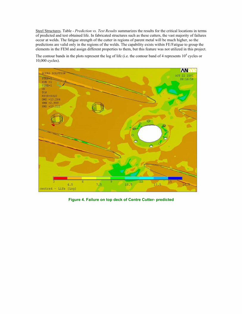
Steel Structures. Table - Prediction vs. Test Results summarizes the results for the critical locations in terms of predicted and test obtained life. In fabricated structures such as these cutters, the vast majority of failures occur at welds. The fatigue strength of the cutter in regions of parent metal will be much higher, so the predictions are valid only in the regions of the welds. The capability exists within FE/Fatigue to group the elements in the FEM and assign different properties to them, but this feature was not utilized in this project.
The contour bands in the plots represent the log of life (i.e. the contour band of 4 represents 104 cycles or 10,000 cycles).
Figure 4. Failure on top deck of Centre Cutter- predicted

Figure 5. Failure on top deck of Centre Cutter-test
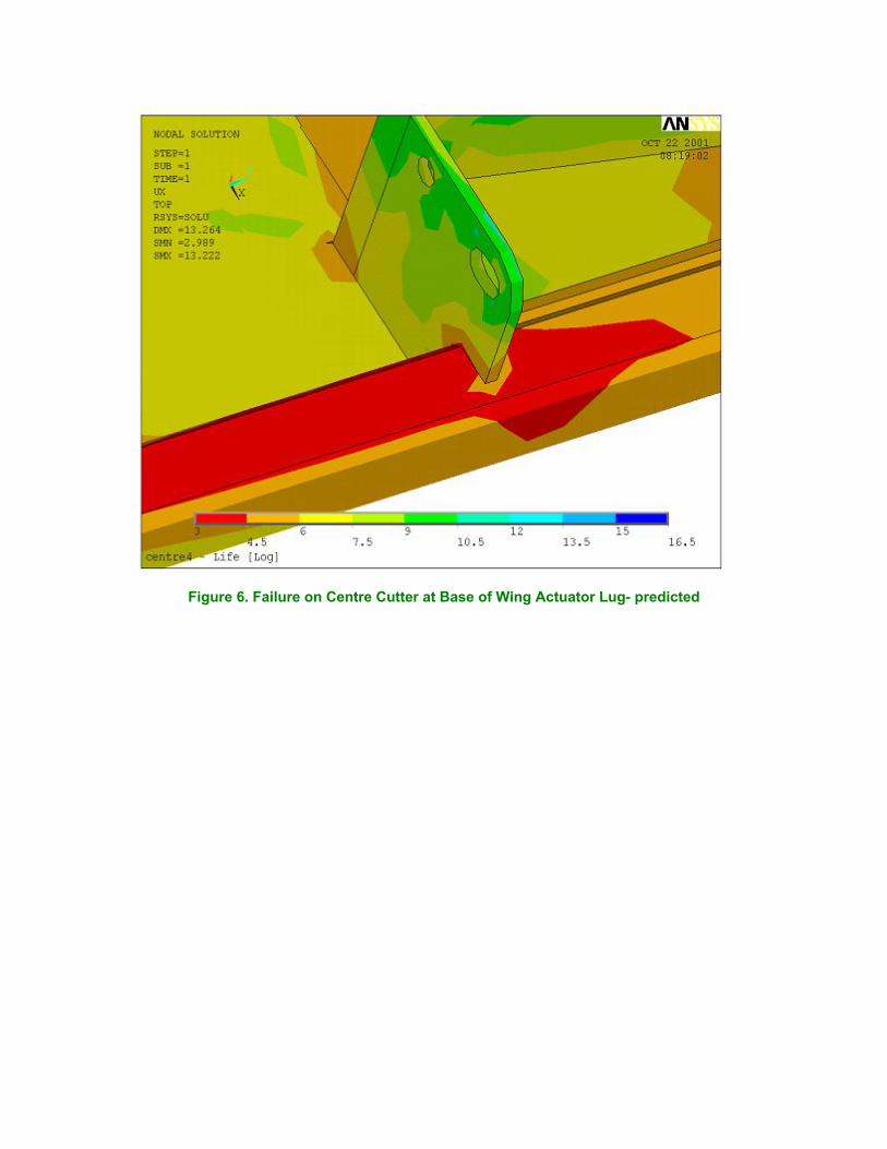
Figure 6. Failure on Centre Cutter at Base of Wing Actuator Lug- predicted

Figure 7. Failure on Centre Cutter at Base of Wing Actuator Lug-test

Figure 8. Failure on Top Deck of Centre Cutter-predicted
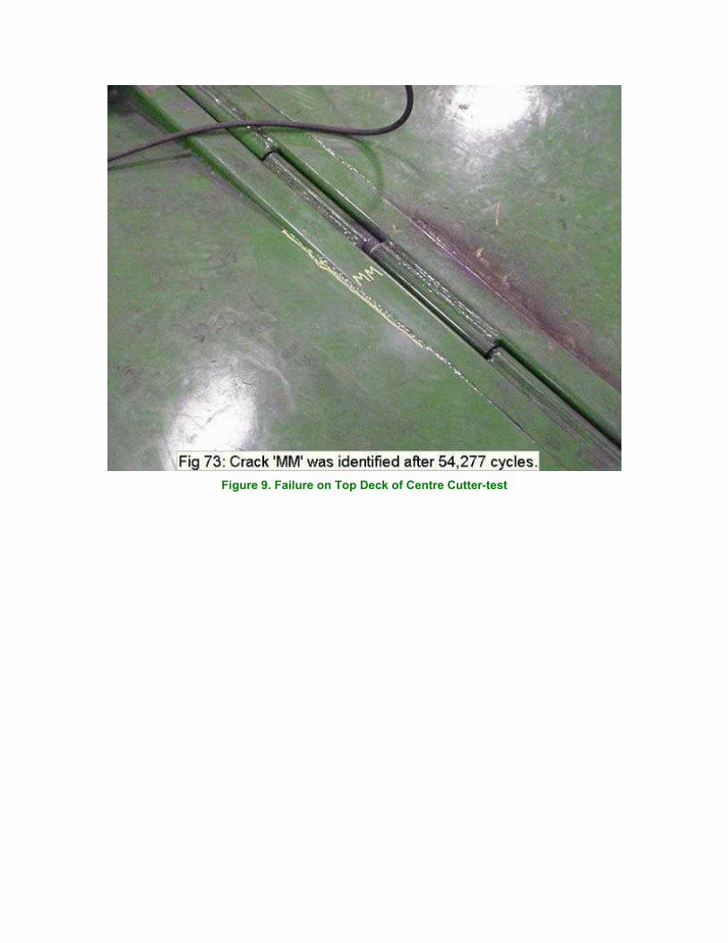
Figure 9. Failure on Top Deck of Centre Cutter-test
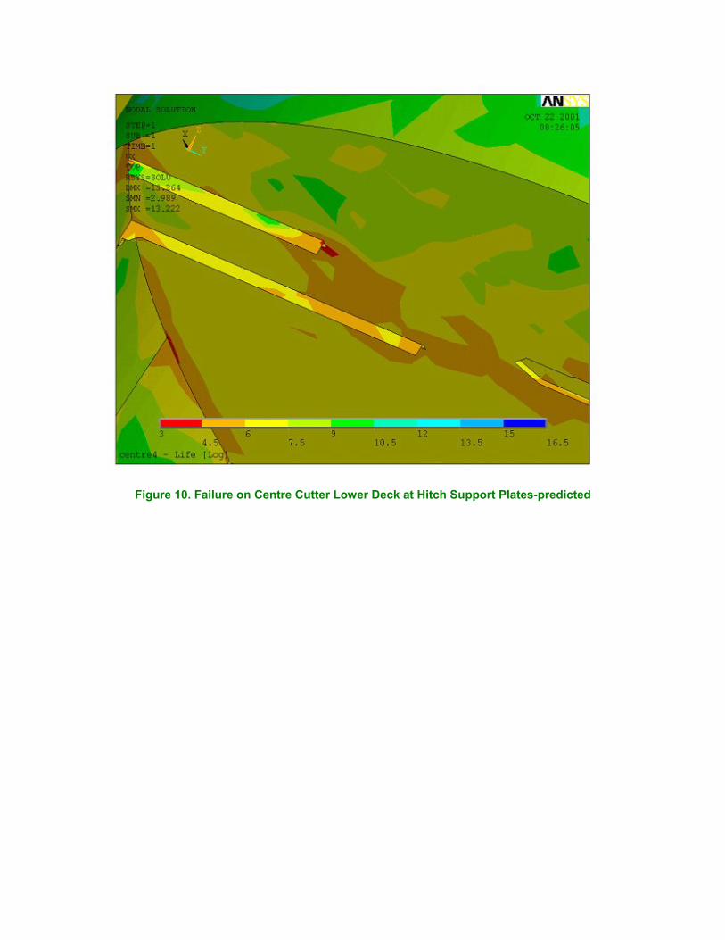
Figure 10. Failure on Centre Cutter Lower Deck at Hitch Support Plates-predicted
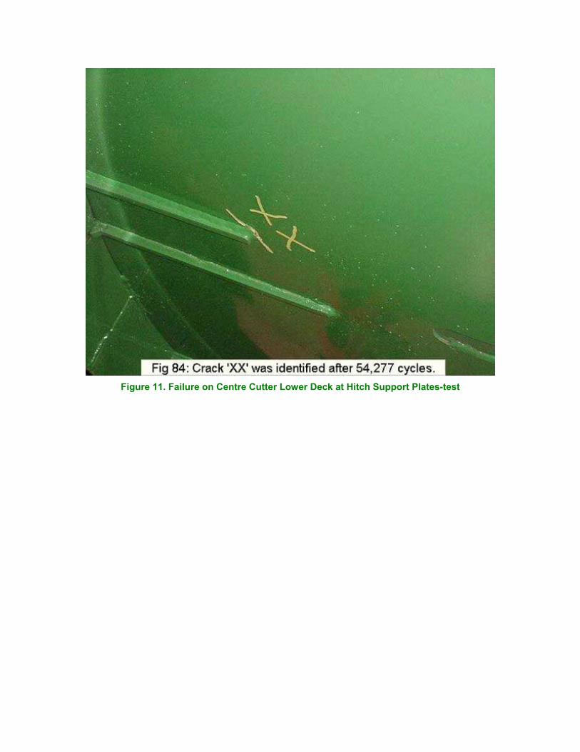
Figure 11. Failure on Centre Cutter Lower Deck at Hitch Support Plates-test

Figure 12. Failure on Centre Cutter Lower Deck at Axle Support Plates-predicted
It is important to note that the durability data on which these predictions are based involve a large amount of scatter. This is particularly true of the weld durability data. Two nominally identical test components could have failure lives that differ by a factor of four or more. The interpretation of the life prediction numbers must be done with this in mind. A prudent approach would be to highlight any location that shows a prediction within, say, five times the design objective (in this case 100,000 cycles), and look at each on an individual basis. The results of the virtual durability assessment in this context are excellent, and show good correlation with the areas of failure on the test.
Prediction vs. Test Results
Crack I.D
Figure Reference
Node I.D.
Predicted Life
Life in Test
MMM 4 12429 24911 77480
K 5 4992 44244 17380
MM 6 12470 19054 54277
XX 7 6411 5152 54277
AAA 8 6247 18155 54277
YY 9 3430 175590 54277
D 10 108661 31260 6651

RRR 11 104934 164437 77561
Q 12 115085 14223 23645
The value of being able to predict service lives based on results obtained exclusively in the virtual domain is obvious. The tools are now available to make this type of analysis possible and practical.
Figure 13. Failure on Centre Cutter Lower Deck at Axle Support Plates-predicted
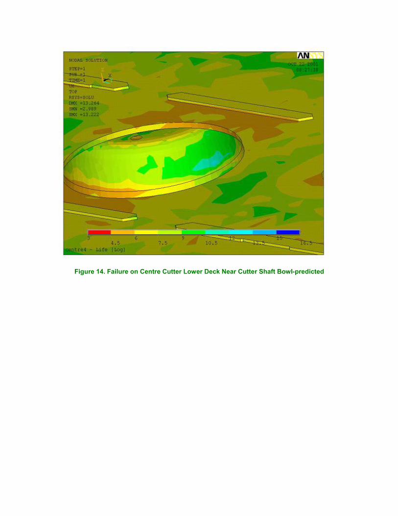
Figure 14. Failure on Centre Cutter Lower Deck Near Cutter Shaft Bowl-predicted
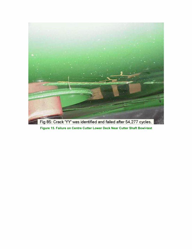
Figure 15. Failure on Centre Cutter Lower Deck Near Cutter Shaft Bowl-test
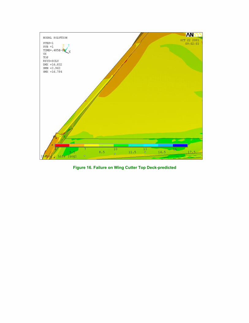
Figure 16. Failure on Wing Cutter Top Deck-predicted
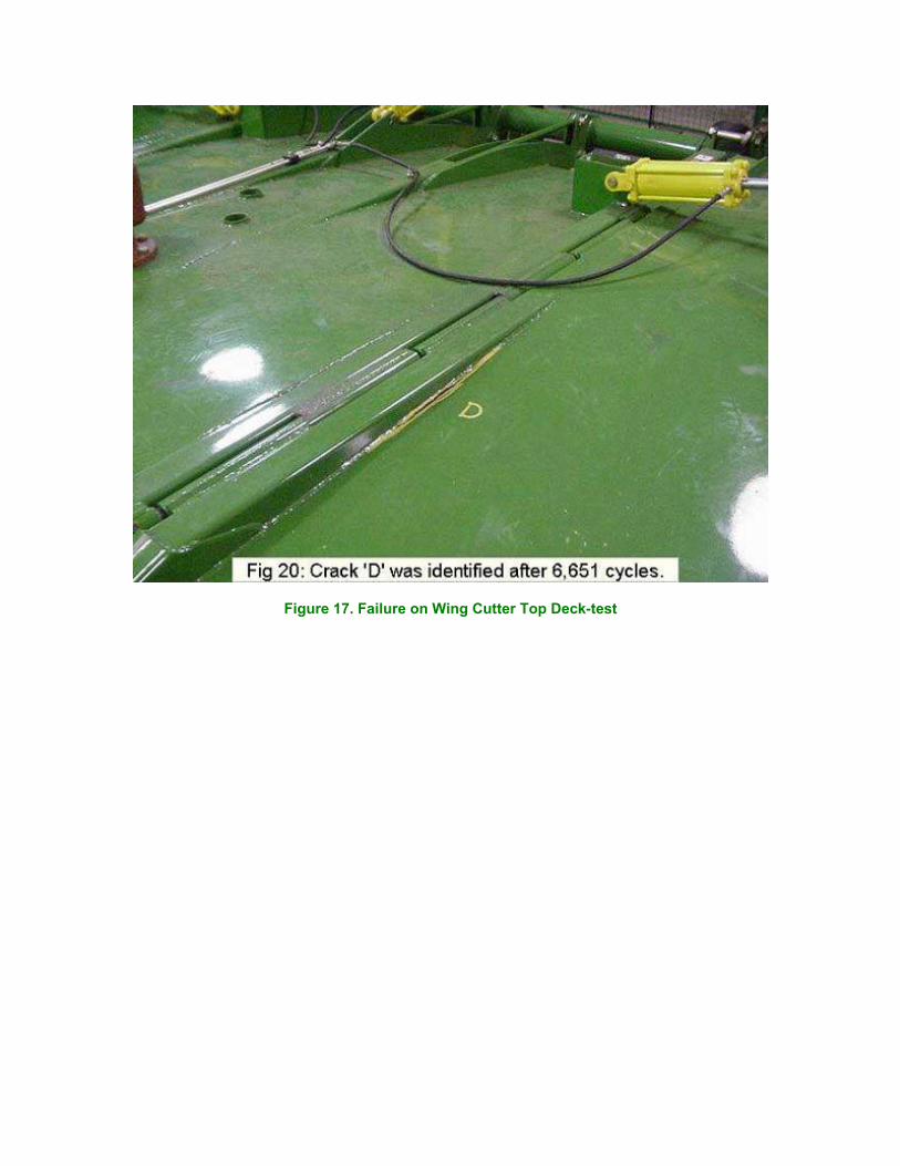
Figure 17. Failure on Wing Cutter Top Deck-test
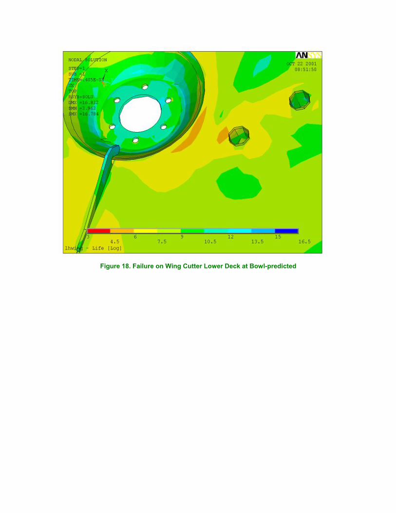
Figure 18. Failure on Wing Cutter Lower Deck at Bowl-predicted
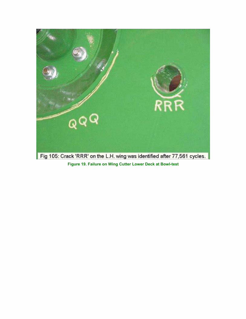
Figure 19. Failure on Wing Cutter Lower Deck at Bowl-test

Figure 20. Failure on Wing Cutter Lower Deck-predicted
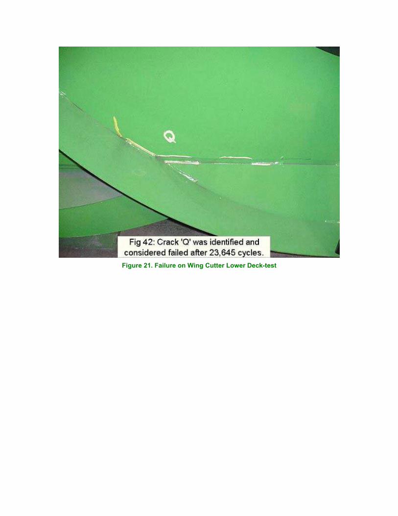
Figure 21. Failure on Wing Cutter Lower Deck-test