Fate of Mercury in Synthetic Gypsum Used for Wallboard ... Library/Research/Coal/ewr... · Fate of...
61
Fate of Mercury in Synthetic Gypsum Used for Wallboard Production Final Report Prepared by: Jessica Sanderson USG Corporation Gary M. Blythe and Mandi Richardson URS Corporation June 2008 Cooperative Agreement No: DE-FC26-04NT42080 USG Corporation 550 West Adams Street Chicago, Illinois 60661 Prepared for: Charles Miller National Energy Technology Laboratory U.S. Department of Energy 626 Cochrans Mill Road Pittsburgh, Pennsylvania 15236
Transcript of Fate of Mercury in Synthetic Gypsum Used for Wallboard ... Library/Research/Coal/ewr... · Fate of...

Fate of Mercury in Synthetic Gypsum Used for Wallboard Production
Final Report
Prepared by:
Jessica Sanderson USG Corporation
Gary M. Blythe and Mandi Richardson URS Corporation
June 2008
Cooperative Agreement No: DE-FC26-04NT42080
USG Corporation 550 West Adams Street Chicago, Illinois 60661
Prepared for:
Charles Miller
National Energy Technology Laboratory U.S. Department of Energy
626 Cochrans Mill Road Pittsburgh, Pennsylvania 15236


iii
DISCLAIMER This report was prepared as an account of work sponsored by an agency of the United States Government. Neither the United States Government nor any agency thereof, nor any of their employees, makes any warranty, express or implied, or assumes any legal liability or responsibility for the accuracy, completeness, or usefulness of any information, apparatus, product, or process disclosed, or represents that its use would not infringe privately owned rights. Reference herein to any specific commercial product, process, or service by trade name, trademark, manufacturer, or otherwise does not necessarily constitute or imply its endorsement, recommendation, or favoring by the United States Government or any agency thereof. The views and opinions of authors expressed herein do not necessarily state or reflect those of the United States Government or any agency thereof.

iv
ABSTRACT This report presents and discusses results from the project “Fate of Mercury in Synthetic Gypsum Used for Wallboard Production,” performed at five different full-scale commercial wallboard plants. Synthetic gypsum produced by wet flue gas desulfurization (FGD) systems on coal-fired power plants is commonly used in the manufacture of wallboard. This practice has long benefited the environment by recycling the FGD gypsum byproduct, which is becoming available in increasing quantities, decreasing the need to landfill this material, and increasing the sustainable design of the wallboard product. However, new concerns have arisen as recent mercury control strategies involve the capture of mercury in FGD systems. The objective of this study has been to determine whether any mercury is released into the atmosphere at wallboard manufacturing plants when the synthetic gypsum material is used as a feedstock for wallboard production. The project has been co-funded by the U.S. DOE National Energy Technology Laboratory (Cooperative Agreement DE-FC26-04NT42080), USG Corporation, and EPRI. USG Corporation is the prime contractor, and URS Group is a subcontractor. The project scope included seven discrete tasks, each including a test conducted at various USG wallboard plants using synthetic gypsum from different wet FGD systems. The project was originally composed of five tasks, which were to include 1) a base-case test, then variations representing differing power plant: 2) emissions control configurations, 3) treatment of fine gypsum particles, 4) coal types, and 5) FGD reagent types. However, Task 5,could not be conducted as planned and instead was conducted at conditions similar to Task 3. Subsequently an opportunity arose to test gypsum produced from the Task 5 FGD system, but with an additive expected to impact the stability of mercury, so Task 6 was added to the project. Finally, Task 7 was added to evaluate synthetic gypsum produced at a power plant from an additional coal type. In the project, process stacks in the wallboard plant were sampled using the Ontario Hydro method. In every task, the stack locations sampled included a gypsum dryer and a gypsum calciner. In Tasks 1 and 4 through 7, the stack of the dryer for the wet wallboard product was also tested. Also at each site, in-stream process samples were collected and analyzed for mercury concentration before and after each significant step in wallboard production. These results and process data were used to construct mercury mass balances across the wallboard plants. The results from the project showed a wide range of percentage mercury losses from the synthetic gypsum feedstocks as measured by the Ontario Hydro method at the process stacks, ranging from 2% to 55% of the mercury in the gypsum feedstock. For the tasks exceeding 10% mercury loss across the wallboard plant, most of the loss occurred across the gypsum calciner. When total wallboard emissions remained below 10%, the primary emission location varied with a much less pronounced difference in emission between the gypsum dryer, calciner and board dryer. For all seven tasks, the majority of the mercury emissions were measured to be in the elemental form (Hg0). Overall, the measured mercury loss mass rates ranged from 0.01 to 0.17 grams of mercury per dry ton of synthetic gypsum processed, or 0.01 to 0.4 pounds of mercury released per million square feet of wallboard produced from synthetic gypsum. The Coal Combustion Product Production and Use Survey from the American Coal Ash Association (ACAA) indicate that 7,579,187 short tons of synthetic gypsum were used for wallboard production in 2006. Extrapolating the results of this study to the ACAA industry usage rate, we

v
estimate that mercury releases from wallboard production plants in 2006 ranged between 150 to 3000 pounds for the entire U.S. wallboard industry. With only seven sets of wallboard plant measurements, it is difficult to draw firm conclusions about what variables impact the mercury loss percentages across the wallboard plants. One significant observation from this study was that higher purge rates of chlorides and fine solid particles from the wet FGD systems appear to produce gypsum with lower mercury concentrations. Any chemical interaction between mercury and chlorides is not well understood; however, based on the information available the lower mercury content in the gypsum product is likely due to the blow down of fine, mercury-rich particles as opposed to a decreased chloride concentration. One possible explanation is that a decrease of fine particles in the FGD slurry allows for less adsorption of mercury onto those particles, thus the mercury remains with the FGD liquor rather than the gypsum product. A more detailed discussion on synthetic gypsum sources and FGD chemistry data can be found in the Experimental section of this report and Table 4. However, higher percentage mercury losses were observed at the wallboard plant for Tasks 3, 5 and 6 with lower feedstock gypsum mercury concentrations that appear to be due to higher chloride and fine particle purge rates at the source FGD systems. This resulted in mercury mass release rates comparable to Tasks 1 and 2 using synthetic gypsum produced in FGD systems on bituminous-coal-fired plants with lower purge rates. There may also be an effect of the coal type fired at the power plant that produces the synthetic gypsum. A test with gypsum produced at a power plant that fires Texas lignite showed lower percentage and mass mercury losses across the wallboard plant than for gypsum from power plants that fire bituminous or subbituminous coal. Selective catalytic reduction (SCR) used for nitrogen oxide emissions control was expected to increase the mercury concentration of the synthetic gypsum; however, results did not support this assumption. It should be noted that the results of this project were measured at USG wallboard plants that use indirect-fired kettle type gypsum calciners. Other calciner types, such as flash calciners where gypsum comes into contact with hot flue gas, may have different mercury release characteristics. Wallboard samples from this project and additional wallboards produced from synthetic gypsum were analyzed for leachate mercury concentration according to the Toxicity Characteristic Leaching Procedure (TCLP). All of the leachates were below detection limits for mercury concentration (<0.3 μg/L) and well below toxicity characteristic thresholds. A laboratory calcination method was tested to determine if laboratory measurements of mercury lost from raw synthetic gypsum feedstock samples would match the corresponding commercial wallboard plant test results. In general, the results did not accurately predict the commercial wallboard plant test results. A more sophisticated laboratory procedure that better simulates heat and mass transfer in a kettle calciner may be required to produce a more reliable prediction. Ten natural gypsum samples were compared to the twelve synthetic gypsum samples described above. The highest mercury concentration found in the natural gypsum was 0.03 μg/g compared to the lowest mercury concentration of synthetic gypsum of 0.10 μg/g.

vi
TABLE OF CONTENTS
Disclaimer ..................................................................................................................... iii Abstract ......................................................................................................................... iv Introduction ................................................................................................................... 1
Background ................................................................................................................. 1 The Wallboard Production Process ............................................................................. 2 Project Overview.......................................................................................................... 4 Report Organization ..................................................................................................... 7
Experimental .................................................................................................................. 9 Rationale for Selecting the Synthetic Gypsums Tested ............................................... 9 Commercial Wallboard Plant Test Procedures .......................................................... 12 Synthetic Gypsum Source Descriptions ..................................................................... 16 Laboratory Procedures .............................................................................................. 24
Results and Discussion .............................................................................................. 30 Commercial Wallboard Test Results .......................................................................... 30 Laboratory Gypsum Calcining Simulation Results ..................................................... 39 Mercury Analyses of Additional Gypsum and Wallboard Samples ............................ 45 TCLP Results on Product Wallboard Samples from Commercial Wallboard Plants .. 46
Conclusions ................................................................................................................. 49 Commercial Wallboard Test Results .......................................................................... 49 Laboratory Test Results ............................................................................................. 51
References ................................................................................................................... 53

vii
LIST OF FIGURES
Figure 1. Simplified Schematic of the Wallboard Production Process Using Synthetic
Gypsum Feedstock ......................................................................................... 3 Figure 2. Schematic of Wallboard Plant Showing Sampling Locations ......................... 13 Figure 3. Observed Relationship Between Mercury Concentration in FGD Liquor and
Chloride Concentration in FGD Liquor and Inert Weight Percent in FGD Slurry ...................................................................................................................... 22
Figure 4. Observed Relationship Between Mercury Concentration in FGD Liquor and Chloride Concentration in FGD Liquor for Samples from Power Plants firing High-sulfur Bituminous Coal (Tasks 1, 2, 3, 5 and 6) .................................... 23
Figure 5. Observed Relationship Between Mercury Concentration in FGD Liquor and Acid Insoluble Inerts in FGD Slurry Solids for Samples from Power Plants firing High-sulfur Bituminous Coal (Tasks 1, 2, 3, 5 and 6) ........................... 23
Figure 6. Observed Relationship Between Mercury Concentration in FGD Liquor and Mercury Content in Raw Gypsum for Samples from Power Plants firing High-sulfur Bituminous Coal (Tasks 1, 2, 3, 5 and 6) ............................................. 23
Figure 7. Schematic of Laboratory Calcining Simulation System .................................. 27 Figure 8. Schematic of the Calcining Simulation Teflon Tube Set Up ........................... 28 Figure 9. Observed Relationship Between Mercury Concentration in FGD Liquor and
Overall Mercury Loss across Wallboard Plant, % for Samples from Power Plants firing High-sulfur Bituminous Coal (Tasks 1, 2, 3, 5 and 6) ................ 36
LIST OF TABLES
Table 1. Planned Project Test Matrix .............................................................................. 5 Table 2. Revised Project Test Matrix ............................................................................... 8 Table 3. Example Power Plant Coal Data ..................................................................... 18 Table 4. Example FGD Absorber Slurry Analysis Results ............................................. 21 Table 5. Summary of Commercial Wallboard Test Results ........................................... 31 Table 6. Summary of Wallboard Test Process Conditions ............................................ 32 Table 7. Laboratory Synthetic Gypsum Calcining Simulation Results Summary ........... 40 Table 8. Mercury Analysis Results for Additional Synthetic Gypsum Feedstock Samples and Wallboard Produced from These Feedstocks.......................... 45 Table 9. Mercury Analysis Results for Natural Gypsum Wallboard Feedstock Samples ........................................................................................................ 46 Table 10. TCLP Results for Commercial Wallboard Samples Produced from Synthetic Gypsum at USG Plants ................................................................. 47
1
INTRODUCTION This report presents and discusses results of the study “Fate of Mercury in Synthetic Gypsum Used for Wallboard Production,” performed at a full-scale commercial wallboard plants. The objective of this project is to measure whether any mercury evolves from synthetic gypsum produced by wet flue gas desulfurization (FGD) systems on coal-fired power plants, when that material is used as a feedstock for wallboard production. The project is being co-funded by the U.S. DOE National Energy Technology Laboratory (Cooperative Agreement DE-FC26-04NT42080), USG Corporation, and EPRI. USG Corporation is the prime contractor, and URS Group is a subcontractor.
Background To address concerns about air quality, the U.S. Congress passed the Clean Air Act Amendments of 1990, which placed significant restrictions on sulfur dioxide emissions from coal-fired power plants. To reduce sulfur dioxide emissions and meet the Clean Air Act standards, many electric utilities installed wet FGD systems on their coal-fired plants. These FGD systems combine the sulfur dioxide gases released during coal combustion with an alkaline reagent such as limestone or lime. In many of these wet FGD systems, the resulting byproduct is oxidized to produce synthetic gypsum. The synthetic gypsum produced is commonly used as a feedstock for wallboard production. The reuse of the synthetic gypsum is environmentally beneficial and is also economically attractive for both the power and wallboard industries. The Clean Air Interstate Rule, signed by the U.S. EPA in March 2005, will further regulate sulfur dioxide emissions. This rule will cause greater amounts of synthetic gypsum to be created, and potentially cause a large increase in the volume of this material to going to landfills. Establishing wallboard manufacturing plants near both power plants and population centers can reduce the quantity landfilled, while making wallboard a more sustainable product by reducing transportation and use of fossil fuels. A number of mercury control strategy plans for U.S. coal-fired power generating plants involve the capture of oxidized mercury from flue gases treated by wet FGD systems. For example, in finalizing the Clean Air Mercury Rule on March 15, 2005, the U.S. EPA recognized mercury emissions reduction “co-benefits” possible for coal-fired plants that are equipped with selective catalytic reduction (SCR) for NOX control and wet FGD systems for SO2 control. SCR systems on bituminous coal fired plants have been observed to oxidize most of the elemental mercury in the SCR inlet gas. Also, a number of proposed mercury control processes involve using low-temperature catalysts or injected chemicals to oxidize elemental mercury and promote increased mercury removal across FGD systems. For these processes to be effective at overall mercury control, the mercury must stay in the FGD byproducts and not be re-emitted to the atmosphere or into groundwater. Measurements by URS Group and others have indicated that much of the mercury scrubbed from flue gases in most U.S. wet FGD systems ends up in the solid byproducts. Thus, mercury stability in FGD solid byproducts is an important aspect of mercury capture in FGD systems.

2
Most FGD systems use lime or limestone reagent and employ forced oxidation to produce gypsum (CaSO4•2H2O) as the solid byproduct. Much of the gypsum byproduct is reused, primarily as a feedstock for wallboard manufacturing. Those that do not produce gypsum instead produce a calcium sulfite hemihydrate (CaSO3•½H2O) byproduct. Most calcium sulfite byproducts are landfilled, although some is reused as mine fill. Approximately 70% of all of the FGD byproduct reuse in the U.S. is gypsum used as wallboard feedstock. During the year 2005, synthetic gypsum from FGD systems represented approximately 30% of the U.S. wallboard plant feedstock. This raises new technical questions: What is the fate of mercury in synthetic gypsum in the wallboard plant process? How much mercury is released into the atmosphere during the production of wallboard using synthetic gypsum? Is the amount of mercury released counterproductive to controlling mercury emissions from coal-fired power plants? Even if mercury is not released in significant quantities during wallboard production, there remains a question as to the stability of mercury in the wallboard product. As an example, at the end of its product life cycle, most wallboard ends up in municipal landfills. What is the stability of mercury in wallboard produced from synthetic gypsum? Will the mercury leach into the acidic aqueous environment in a municipal landfill? This project was intended to collect data from commercial wallboard plants processing FGD synthetic gypsum to help answer these questions.
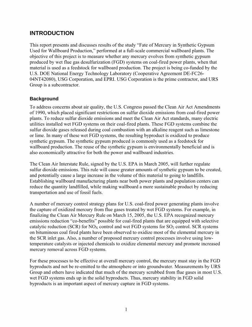
The Wallboard Production Process Figure 1 shows an overview of the wallboard production process. In the process, synthetic gypsum is dried to produce “land plaster,” which is gypsum that contains no free moisture, only chemically bound waters of hydration. The land plaster is then calcined to produce the “beta” form of calcium sulfate hemihydrate according to the following chemical reaction:
2 CaSO4•2H2O + heat ↔ 2 CaSO4•½H2O + 3 H2O
The beta hemihydrate is also commonly called “stucco” or “plaster of Paris.” The stucco is subsequently mixed with water and a number of additives to form a slurry that is extruded between two sheets of paper to form the wallboard. The hemihydrate re-hydrates to form gypsum by the reverse of the reaction shown above. This re-hydration consumes much of the water in the slurry, and causes the gypsum formed to set up as a cohesive solid. The wet board travels down a conveyor belt while it is setting up. After adequate residence time to set up, the board is cut to approximate length, and then dried to remove free moisture (excess water not consumed by the re-hydration reaction). The dried product is cut to final length then stacked for shipping. The initial gypsum drying and calcining steps described above occur in a section of the plant called the mill. The dryers are typically direct fired with natural gas. Their purpose is to remove the free moisture in the synthetic gypsum (typically 8 to 12% by weight of the raw material) prior to calcining. The dryers consequently operate at conditions below the required gypsum calcining temperature of 262oF (128oC). The solids are dried by direct contact between the wet particles

3
Synthetic Gypsum Storage
Dryer Mill/ Dust Collector
Dryer Mill Stack
Kettle Steam Stack
Silo Stucco Storage Bin
Kettle Calciner
AdditivesWater, Additives
Top Paper
Bottom Paper
Board Processing, Stacking
Board Dryer
Belt Table
Rotary Knife
Forming Rolls
Wet Plaster Mixer
Mixing Conveyor
Board Dryer Stack
Transfer and Board Turner
Wallboard Product
Mill
Board Line
Kettle Dust Collector
Figure 1. Simplified Schematic of the Wallboard Production Process Using Synthetic
Gypsum Feedstock and the hot flue gas. The moisture-free synthetic gypsum (land plaster) is collected in a fabric filter and placed in intermediate storage silos prior to feeding to the calciners. In the calcining step, the solids temperature must be raised above 262oF (128oC) to promote release of 1-½ waters of hydration, but must be kept below 325oF (163oC) to avoid forming anhydrous calcium sulfate (no remaining waters of hydration). The calciners used at the wallboard plant tested are indirect-fired kettle calciners, so the vent gas from the process side of the kettle is primarily a mixture of steam and air. A kettle calciner dust collector removes fine stucco particles from this vent gas. The recovered fine particles are recycled to the kettle calciner feed or added to the calciner product stream. The stucco leaving the kettle is cooled and placed in a bin for intermediate storage, to provide a buffer between the mill and board line. In the board line, the stucco from the silo is fed to a mixer, where “gauging” water is added to form a viscous slurry. The gauging water is typically of high quality (e.g., potable water). A number of proprietary additives are mixed with the wet slurry produced from the stucco. This wet slurry is continuously extruded between two sheets of paper that are fed from rolls above and below the extruder. One type of paper is used for the face of the wallboard product

4
and another type is used for the back. The formed board travels down a long conveyor belt that provides residence time for the stucco to re-hydrate and take a set. At the end of this belt, the formed board is cut and inverted so the face paper is facing up. The board then enters a dryer. The dryer is zoned to operate over a range of temperatures, typically over 400oF (204oC) air temperature at the dryer entrance and about 200oF (93oC) air temperature at the exit. However, the board residence time in the dryer is controlled to limit the temperature of the dried board. This temperature must be limited to avoid any of the set-up solids re-calcining to the hemihydrate form. Thus, the bulk of the rehydrated gypsum in the wallboard product stays well below 262oF (128oC) in temperature. From the dryer, the dried board is cut to final size, has end tape applied, and is stacked for shipment. Any potential mercury losses during the wallboard process are assumed to occur during the thermal processes, with losses most likely to occur during the calcining step. The synthetic gypsum particles are raised to the highest temperature in the process during this step (above 262oF [128oC]). Losses are also possible from the synthetic gypsum dryer and the finished wallboard dryer, although the maximum temperatures to which the gypsum is raised are lower in the dryers (approximately 170oF to 230oF [77oC to 110oC]).
Project Overview This project was intended to provide information about the fate of mercury in synthetic gypsum produced by FGD systems on coal-fired power plants, when used as feedstock for wallboard production. Solid samples from various locations in the wallboard process, including the wallboard product, were collected and analyzed for mercury content. Simultaneous flue gas measurements were made using the Ontario Hydro method to quantify any mercury releases to the atmosphere during wallboard production. The project was set up to include five tasks, each of which included a full-scale wallboard plant test conducted while processing synthetic gypsum with unique source conditions. As the project progressed, a sixth and seventh task were added, representing new synthetic gypsum source conditions. Most of the testing was concentrated in the mill processes where the synthetic gypsum is dried and calcined. Any potential mercury releases from the synthetic gypsum solids are thought to result from thermal desorption. It is in the mill portion of the process where the feedstock sees the highest process temperatures and where the evolution of waters of hydration may promote mercury desorption. Initially, a limited amount of testing was to be conducted in the downstream board line, where the calcined gypsum is slurried, mixed with proprietary additives and formed into wallboard. The project plan was for the board dryer kiln stack flue gas to only be measured for mercury content at the first test site (Task 1). Lesser mercury release was expected in the board dryer kiln because it is downstream of the mill, and the rehydrated gypsum solids typically see lower temperatures than in the mill. However, once results were available from Task 1 showing appreciable mercury loss from the board dryer kiln stack, stack testing for the board dryer kiln was added to the project scope for Tasks 4 through 7.

5
Process solid and flue gas mercury concentrations and plant process data were used to calculate mercury balances around each operating wallboard plant, to help confirm measured mercury loss rates. Samples of synthetic gypsum tested were evaluated in laboratory calcining tests to provide comparison data and to evaluate a lab technique for screening synthetic gypsum samples for mercury loss in the wallboard process. Also, wallboard produced from synthetic gypsum was leached according to the Toxicity Characteristic Leaching Procedure (TCLP) to provide an indication whether wallboard disposed of in municipal landfills will have a tendency to release mercury into groundwater. The TCLP test was chosen based on current regulations; however future studies may include a more comprehensive set of leachate procedures. Samples of natural gypsum were also collected and analyzed for mercury content, for comparison with the mercury content of the synthetic gypsums tested in the wallboard plants. The project has investigated wallboard produced from a variety of synthetic gypsum sources, all from FGD systems on coal-fired power plants but from different coal types, power plant emissions control configurations, and FGD conditions. The project was originally structured in five tasks. As shown in Table 1, each involved one commercial wallboard plant test.
Table 1. Planned Project Test Matrix Task 1 2 3 4 5 Synthetic Gypsum Source: Power Plant A A B C D Coal Type High sulfur
bituminous High sulfur bituminous
High sulfur bituminous
Texas lignite High sulfur bituminous
FGD Reagent Limestone Limestone Limestone Limestone Lime Forced Oxidation Mode In Situ In Situ In Situ In Situ External Gypsum Fines Blow Down?
No (or Low Rate)
No (or Low Rate)
Yes No Yes
SCR Operating? Yes No Yes No TBD* USG Wallboard Plant Tested
1 1 2 3 1
*To be determined later based on the time of the year of the test
To investigate five different synthetic gypsum feedstocks, testing was to be conducted at three different USG wallboard plants, since no one plant uses all five as a feedstock. The relationship between synthetic gypsum types and USG plants originally planned for investigation is also shown in Table 1. Note that the power plants and USG wallboard plants are not identified by name, only by letter or number codes, in accordance with an agreement for anonymity at the beginning of the project. The first four tasks included tests on synthetic gypsum feedstocks produced from: • Task 1 – The base case, a power plant that fires medium- to high-sulfur bituminous coal and
that has an SCR for NOX control, a limestone forced oxidation (LSFO) FGD system that

6
produces wallboard grade gypsum byproduct, and has only limited blow down of chlorides and gypsum fines from the FGD system.
• Task 2 – The same power plant included in Task 1, but without the SCR operating (SCR
catalyst bypassed). Since SCR catalysts have been observed to promote mercury oxidation, taking the SCR out of service might impact the amount of mercury captured in the FGD byproduct and could impact mercury losses during wallboard production,
• Task 3 – A high-sulfur, bituminous LSFO plant with SCR that operates with a relatively high
chloride and gypsum fines blow down rate, and • Task 4 – A plant that fires Texas lignite rather Eastern bituminous coal, and that does not
have SCR.
Each of these variables was thought to impact the amount of mercury in the synthetic gypsum feedstock and/or possibly impact the stability of that mercury in the wallboard production process. The effects of these variables, as anticipated at the beginning of the project, are further discussed in the Experimental section. As shown in the table, the project plan was for the fifth task to investigate a synthetic gypsum feedstock produced by a power plant that fires Eastern high-sulfur bituminous coal and that has an SCR for NOX control, but it was not certain whether the SCR would be in operation when the gypsum to be tested would be produced. The major variable to be evaluated in Task 5 was the effect of FGD reagent. While the other four tasks tested gypsums produced from FGD systems that use limestone reagent with in situ (in the FGD absorber reaction tank) forced oxidation, Task 5 was to test gypsum produced from an FGD system that uses lime reagent and forced oxidizes the byproduct in a tank external to (downstream of) the absorber loop. However, the logistics for conducting Task 5 using gypsum from Power Plant D proved to be difficult. USG Wallboard Plant 1 normally processes a blend of gypsum from Power Plants A and D, with Power Plant D material comprising less than half. And, since the gypsum from Power Plant A was expected to have a higher mercury content than that from Power Plant D, a blend of the two was deemed to be inappropriate for Task 5. Because of space limitations at the wallboard plant, it proved very difficult to stockpile enough material to allow the wallboard plant to gradually transition to processing 100% material from Power Plant D. After an extended period over which the wallboard plant unsuccessfully attempted to achieve that goal, it was decided to modify the project plan for Task 5. The highest mercury percent losses measured in the first four tasks were in Task 3, where the gypsum was produced by a power plant that fires high-sulfur Eastern bituminous coal, has an SCR in service, uses limestone FGD reagent, and incorporates a high chloride and gypsum fines blow down rate as part of the gypsum dewatering scheme. It was decided to test synthetic gypsum from a second system (Power Plant E) with a similar configuration in Task 5, to see if similarly high mercury losses would be measured. One difference between Tasks 3 and 5 is that for Task 5, the power plant that produced the synthetic gypsum did not have its SCR in service

7
(i.e., catalyst bypassed). However, based on results from Tasks 1 and 2, this was not thought to be a significant factor. After conducting Task 5, it was apparent that mercury losses were very similar to the Task 3 results, on both a percentage and mass basis, and thus higher than the losses measured as part of Tasks 1, 2 and 4. As part of another DOE Cooperative Agreement, DE-FC26-04NT42309, (subsequently referred to as DOE Project 42309) an FGD additive was tested for improving net capture of oxidized mercury by wet FGD systems. This additive, Evonik Degussa Corporation’s TMT-15, is further described in the Experimental section of this report. As part of DOE Project 42309, full-scale TMT-15 tests were conducted at Power Plant E. This offered the opportunity to test synthetic gypsum from Power Plant E with TMT-15 addition at Wallboard Plant 4, for comparison to the previous Task 5 results without TMT addition. DOE-NETL agreed to co-fund this additional test, and Task 6 was added to the project. After Task 6 was completed, USG began processing synthetic gypsum from a power plant that fires Powder River Basin (PRB) coal. Although Task 4 in the original test matrix had involved testing gypsum from an FGD system on a power plant that fires a low-rank coal – Texas lignite – this new wallboard plant feedstock offered the opportunity to test synthetic gypsum from a third coal type. Again, DOE-NETL agreed to co-fund this additional test and Task 7 was added to the project. The revised project test matrix is shown in Table 2, including the change to testing gypsum from Power Plant E rather than Power Plant D in Task 5, and the addition of Tasks 6 and 7. One difference between Tasks 5 and 6 besides TMT-15 addition is that for Task 5, the SCR was not in service (bypassed) on Power Plant E when the synthetic gypsum was produced, while for the Task 6 gypsum it was in service. However, based on results from Tasks 1 and 2, and by comparison of Task 3 and Task 5 results, this was not thought to be a significant factor. This report presents and discusses the results of the wallboard plant tests conducted in all seven tasks. Previous Topical Reports have presented in detail and discussed the results of individual tests conducted as part of Tasks 1 through 71-7, including Ontario Hydro measurements in the dryer mill, kettle calciner, and board kiln, process sample mercury content, process data, and mercury balance results. This final report discusses these results at a summary level; the reader can review each of the Topical Reports as needed to find more details about individual tests. Laboratory evaluations were also planned as part of the project, including simulated gypsum kettle calciner tests, analyses of a range of synthetic and natural gypsums for mercury content, and mercury leaching from wallboard product samples by TCLP. These results have not been previously reported, and so are included in this final report.
Report Organization The remainder of this report is organized into four sections: Experimental, Results and Discussion, Conclusion, and References. The section entitled Experimental describes the experimental methods used to conduct the mercury testing at a commercial wallboard plant as part of the seven tasks, including stack testing, process sampling, and off-site chemical analyses. Also included in the Experimental section are further descriptions of the four power plants and

8
Table 2. Revised Project Test Matrix Task 1 2 3 4 5 6 7 Synthetic Gypsum Source: Power Plant
A A B C E E F
Coal Type High-sulfur bituminous
High-sulfur bituminous
High-sulfur bituminous
Texas lignite
High-sulfur bituminous
High-sulfur bituminous
Powder River Basin
FGD Reagent
Limestone Limestone Limestone Limestone Limestone Limestone Limestone
Forced Oxidation Mode
In Situ In Situ In Situ In Situ In Situ In Situ In Situ
Gypsum Fines Blow Down?
Low Low High None High High Variable
SCR Operating?
Yes No Yes No No Yes Yes
TMT-15 Addition to FGD?
No No No No No Yes No
USG Wallboard Plant Tested
1 1 2 3 4 4 5
their FGD systems that produced the synthetic gypsums tested at the wallboard plants, and descriptions of laboratory procedures used during the project. The Results and Discussion section presents results from the full-scale wallboard plant tests, and from the laboratory evaluations described above. The Conclusion section provides conclusions that can be made from the results of these commercial wallboard plant mercury tests, and associated laboratory tests.

9
EXPERIMENTAL A description of the project test matrix was provided in the Introduction section. This section begins with an explanation of the rationale used for choosing these six FGD synthetic gypsums as a wallboard plant feedstock for the seven tasks. The remainder of the section presents details of how the wallboard plant mercury tests were conducted, descriptions of the power plants and FGD systems that produced the synthetic gypsums tested, and how the various laboratory tests were conducted as part of this project.
Rationale for Selecting the Synthetic Gypsums Tested The first wallboard plant test involved measuring the fate of mercury in synthetic gypsum from a high-sulfur, bituminous-coal-fired power plant equipped with an operating SCR and with an LSFO FGD system that employs only limited fines blow down from the FGD system (Power Plant A). This combination was selected for the first test because the synthetic gypsum produced at Power Plant A has a relatively high mercury content. Higher mercury content was expected to enhance the accuracy of the tests. Furthermore, previous laboratory testing funded by EPRI8 and initial full-scale tests by USG9 suggest that small measurable mercury losses could be expected from this feedstock during wallboard production. For these reasons, it was thought that testing this material as the base case could be a USG worst-case scenario for potential mercury losses during wallboard production. The second wallboard plant test involved measuring the fate of mercury in synthetic gypsum from the same source as the first test (Power Plant A) except the SCR was bypassed. Previous testing has shown that, at least for some plants that fire high-sulfur bituminous coal, having an SCR in service tends to increase the percentage oxidation of mercury in the flue gas upstream of an FGD system, and to increase the percentage capture of mercury in the FGD system.10,11 Many plants that are equipped with SCR only operate them during the “ozone season,” from May 1 through September 30 each year, and bypass the SCR catalyst the remainder of the year. For such plants, one might expect that synthetic gypsum produced from their FGD systems would contain more mercury with the SCR operating during the ozone season than that produced during the remainder of the year. The third wallboard plant test involved measuring the fate of mercury in synthetic gypsum from a high-sulfur bituminous-coal-fired power plant equipped an operating SCR and with an LSFO FGD system that employs aggressive chloride and fines blow down from the FGD system (Power Plant B). Gypsum fines blow down is believed to be an important variable and will be discussed over the next few paragraphs. Most synthetic gypsum used as a wallboard plant feedstock is subject to a number of quality control specifications by the wallboard manufacturer including maximum moisture content, minimum gypsum content, maximum chloride content, and particle size distribution. These parameters are specified because they impact energy consumption at the wallboard plant, solids handling properties, and wallboard product properties such as weight, strength and paper adhesion. A number of FGD variables affect the ability to meet the solids particle size distribution specification. These variables include the gypsum crystal residence time in the FGD absorber

10
loop, FGD reagent chemical composition, and the amount of physical abrasion to which the crystals are exposed as they are recirculated and dewatered. Some FGD systems cannot meet the wallboard manufacturer’s particle size specification unless they separate a portion of the byproduct containing the smallest particle sizes. This separation is typically accomplished with hydrocyclones. The separated fines are either discarded or sold for other uses. Many FGD systems need to purge a portion of the hydrocyclone overflow as a means of limiting chloride buildup in the FGD liquor. These plants blow down gypsum fines as part of the chloride purge. In a few FGD systems, there is no need to separate the fines and/or purge chlorides, and all of the fines are included in the byproduct sent to the wallboard plant. Laboratory testing conducted by URS for EPRI indicated that the mercury concentration in gypsum fines can be as much as an order of magnitude higher than in the larger particles.8 This might suggest that mercury precipitates or adsorbs at gypsum surfaces, since the fines have a much higher surface area to mass ratio than larger particles. However, recent results from DOE laboratory evaluations suggest that mercury primarily adsorbs on fine particles of impurities, which enter the FGD system with fly ash or with the FGD reagent.12 Upwards of half of the mercury removed by the FGD system can be in the fines. Thus, by purging FGD liquor to reduce chloride concentrations, the concentration of fines is simultaneously reduced, significantly lowering the mercury concentration in the synthetic gypsum byproduct going to the wallboard plant. Since Power Plant A providing the feedstock for Task 1 employs only a limited fines blow down rate, and operates with relatively high FGD liquor chloride concentrations, it was expected to have a higher mercury content in the synthetic gypsum byproduct than would a similar plant with higher blow down rates. This byproduct might thermally evolve more mercury in the wallboard mill than would a byproduct with the fines removed and a lower total mercury concentration. Also, Power Plant A was known to fire a coal blend with a relatively high mercury content. This first case was chosen to represent conditions that, for the reasons described above, were believed most likely to show measurable mercury losses during the wallboard production process. It was anticipated that the other synthetic gypsum feedstocks might show reduced mercury evolution, but full-scale testing was required to confirm or deny such assumptions. Task 2 involved testing at Wallboard Plant 1 and with gypsum from Power Plant A, as during Task 1, but with material produced while the SCR was not in service (catalyst bypassed). As for the material tested as part of Task 1, the Power Plant A FGD system was operated with low chloride and fines blow down rates. It was expected that with the SCR out of service, the synthetic gypsum produced from the Power Plant A FGD system would contain less mercury than during the ozone season, with the SCR in service. It was thought that if less mercury were contained in the gypsum produced with the SCR out of service, it might correspondingly reduce the amount of mercury thermally evolved in the wallboard plant. The plant providing the feedstock for Task 3 test employs a high chloride and fines blow down rate; it was therefore expected to have lower mercury content in the synthetic gypsum byproduct than would a similar plant with a low fines blow down rate (e.g., Power Plant A). Because of this, the Power Plant B byproduct might thermally evolve less mercury in the wallboard plant than a byproduct with more of the fines included and a higher total mercury concentration.

11
The fourth wallboard plant test involved measuring the fate of mercury in synthetic gypsum from a power plant that fires Texas lignite fuel (Power Plant C). The testing in Tasks 1 through 3 was conducted at wallboard plants processing synthetic gypsum from high-sulfur, bituminous-coal-fired plants. Most synthetic gypsum processed in wallboard plants comes from bituminous coal sources. However, a growing amount of wallboard is produced from synthetic gypsum produced in scrubbed power plants that fire low rank coals such as lignite or Powder River Basin (PRB) fuels. Low rank coals differ from high-sulfur bituminous coals in a number of manners that impact mercury in the synthetic gypsum. For example, low-rank coals typically have lower chloride content than bituminous coals, which results in lower mercury oxidation percentages in the FGD inlet flue gas. This could result in lesser amounts of mercury being removed in the FGD systems. However, from the standpoint of mercury concentrations in the synthetic gypsum, this effect is offset to some degree by the fact that the lower rank coals typically have lower sulfur content, and hence produce less gypsum per mass of coal fired. There is evidence, at least from one laboratory evaluation, that synthetic gypsum from low-rank coals behaves differently when dried and calcined in a wallboard plant than gypsum from bituminous coal. In a laboratory study conducted for EPRI, calcining simulations were conducted on five different synthetic gypsum samples. In these studies, synthetic gypsum samples from a Texas lignite fired power plant and from a PRB-fired plant showed measurably lower percentage mercury losses than three samples from high-sulfur, bituminous coal plants.8 This observed difference may have been coincidental, since the number of samples from each coal type was small. However, these results suggested that coal rank would be an important variable to investigate as part of this project. Therefore, Tasks 4 and 7 measured mercury losses while producing wallboard from synthetic gypsum produced at power plants that fire Texas lignite and PRB, respectively. The fifth wallboard plant test involved measuring the fate of mercury in synthetic gypsum from a FGD system similar to that which provided the material tested in Task 3 (Power Plant E). Originally, Task 5 was to be conducted with lime rather than limestone as the FGD reagent used to produce the synthetic gypsum tested. However, as described in the Introduction, the logistics were not favorable for conducting a wallboard test on 100% material from Power Plant D, so Task 5 was conducted with synthetic gypsum from an FGD system similar to that which provided the material tested in Task 3. This was condition was tested again with another synthetic gypsum source because of the relatively high mercury percentage loss across the wallboard plant measured in Task 3. The sixth wallboard plant test involved measuring the fate of mercury in synthetic gypsum from the same power plant (Power Plant E) that produced the material tested in Task 5, except an additive, TMT-15, had been used in the FGD system while the Task 6 material was produced. In wet FGD absorbers, the oxidized form of mercury (Hg+2) is absorbed from the flue gas into the FGD liquor, while water insoluble elemental mercury (Hg0) is typically not removed. Once absorbed, the Hg+2 can follow as many as three pathways for leaving the FGD system. These include: 1) Undergoing reduction reactions while in the FGD liquor to form Hg0, which, being

12
insoluble is released and re-emitted into the FGD outlet flue gas; 2) Being retained in the FGD liquor, and potentially becoming a regulatory compliance issue in FGD blow down liquor; or 3) Being retained in the FGD byproduct solids. DOE Project 42309 investigated the use of FGD additives to rapidly precipitate mercury in FGD liquor as a solid salt, to minimize pathways 1 and 2. One additive tested, trimercapto-s-triazine, tri-sodium salt (TMT), is commercially available from Evonik Degussa Corporation as a 15-wt% aqueous solution (TMT-15). TMT-15 has reportedly been used in Europe in wet FGD systems on a number of waste incineration plants and several coal-fired power plants to precipitate dissolved mercury as a stable salt, lower liquid-phase mercury concentrations, and minimize re-emissions.13 While TMT-15 has been used in Europe in FGD applications, it has not seen widespread use in U.S. plants. DOE Project 42309 provided an opportunity to evaluate the use of TMT-15 for these purposes on pilot- and full-scale wet FGD systems on U.S. coal-fired units. The reaction of TMT with heavy metals is based on the soluble tri-sodium salt chemically binding to heavy metals via sulfur groups. In the process, high-molecular-weight organo-metallic compounds are produced which have a very low aqueous solubility. They precipitate as solid substances and can be separated from the liquor by filtration. In the FGD slurry sent to dewatering, fine particles of mercury-TMT compound can be transferred to the chloride/fines blow down stream, returned to the absorber and/or partly included with the byproduct gypsum. TMT-metal compounds are reportedly quite stable with respect to temperature. According to Evonik Degussa, temperatures in excess of 410°F (210°C), which is well above the gypsum calcining temperature, are needed to begin to decompose the mercury-TMT salt, and TMT-metal compounds easily meet the leachability limits of the TCLP. It was anticipated that any mercury bound as a TMT salt that remains in FGD byproduct gypsum would remain stable and not be volatilized into the flue gas in significant percentages when the gypsum is processed in a wallboard plant. Task 6 of this project was intended to determine the effectiveness of TMT-15 for this purpose when added to an FGD system. The seventh wallboard plant test involved measuring the fate of mercury in synthetic gypsum from a power plant that fires Powder River Basin (PRB) fuel (Power Plant F). The source is similar to the material tested in Task 4 but is another type of low rank coal. The rationale for selecting low rank coals is described in more detail above in the description for the fourth wallboard test.
Commercial Wallboard Plant Test Procedures Commercial wallboard plants often operate with a blend of feedstock from a number of FGD systems. Rarely does one power plant generate enough synthetic gypsum to feed the entire production of a modern wallboard plant, so most wallboard plants process synthetic gypsum from two or more power plants. Each synthetic gypsum has unique processing conditions within the wallboard plant process. Therefore, to minimize excessive swings in wallboard plant operating conditions, most plants blend the available feedstock to produce an “average” material for processing. For these seven tests, the intent was for the wallboard plant to be operated on 100% feedstock from Power Plants A, B, C, E or F. It would be more difficult to elucidate the effects of power

13
plant and FGD variables on mercury losses during wallboard production if synthetic gypsum blends were being processed during measurements. Also, the feedstock to the mill typically contains recycled material, which can include recycled wallboard, wallboard samples, material recycled from the calciner during shut downs, etc. Because recycle consists of material from a variety of sources, it was felt that recycle would add variability to the incoming feed mercury concentration and possibly its stability. Therefore, the wallboard plant tests were conducted with no recycle feed to the plant during any of the sampling runs. Two days of wallboard plant testing were typically conducted, with the first day testing in the mill and the second day in the board line as described below. Figure 2 illustrates the wallboard production process.
Synthetic Gypsum Storage
Dryer Mill/ Dust Collector
Dryer Mill Stack
Kettle Steam Stack
Silo Stucco Storage Bin
Kettle Calciner
AdditivesWater, Additives
Top Paper
Bottom Paper
Board Processing, Stacking
Board Dryer
Belt Table
Rotary Knife
Forming Rolls
Wet Plaster Mixer
Mixing Conveyor
Board Dryer Stack
Transfer and Board Turner
Wallboard Product
Mill
Board Line
Kettle Dust Collector
S1
S
S S
S
S2 S3
S6
S8S9S10
S11
S12S13
S14b
S5 S7
S14a
Synthetic Gypsum Storage
Dryer Mill/ Dust Collector
Dryer Mill Stack
Kettle Steam Stack
Silo Stucco Storage Bin
Kettle Calciner
AdditivesWater, Additives
Top Paper
Bottom Paper
Board Processing, Stacking
Board Dryer
Belt Table
Rotary Knife
Forming Rolls
Wet Plaster Mixer
Mixing Conveyor
Board Dryer Stack
Transfer and Board Turner
Wallboard Product
Mill
Board Line
Kettle Dust Collector
S1S1S1
SSS
SS SS
SSS
S2S2S2 S3S3S3
S6S6S6
S8S8S8S9S9S9S10S10S10
S11S11S11
S12S12S12S13S13S13
S14bS14bS14b
S5S5S5 S7S7S7
S14a
Figure 2. Schematic of Wallboard Plant Showing Sampling Locations
Process streams that were typically sampled as part of the test, as described below, are marked with “S” followed by a number that represents a sample location. The sample locations varied some from test to test, though. Not all of the wallboard plants have sampling ports at every location shown in Figure 2, and some had sample points not shown in the figure. Figure 2 shows two stacks on the board dryer kiln, but Wallboard Plants 1, 2 and 5 have only a single stack. Also, as was discussed in the Introduction, the board dryer kiln stack was not sampled during Tasks 2 and 3.

14
Day 1 – Mill Testing
Stack Sampling
On the first test day, simultaneous gas measurements were conducted using the Ontario Hydro method14 on a raw gypsum dryer stack and a downstream kettle calciner dust collector (steam) stack. Wallboard Plants 1 and 2 have two separate process trains consisting of a dryer and kettle calciner while Wallboard Plants 3 and 4 have only one dryer feeding two kettle calciners. Wallboard Plant 5 was operating only one dryer and one kettle calciner during most of the testing period. In each test, one dryer stack and one kettle calciner stack was sampled (in the same process train at Wallboard Plants 1 and 2). As noted in the previous Topical Reports for this project, the Ontario Hydro method was modified slightly for sampling at the kettle calciner steam stack, as described below. Triplicate Ontario Hydro method sampling runs were made at each of these two locations. The kettle calciners are indirect-fired vessels. The gaseous stream from the calciner that could contain mercury from the synthetic gypsum is the “steam stack,” which is a mixture of the water calcined from the gypsum when forming stucco (CaSO4•½H2O) and aeration air introduced at the bottom of the kettle. The other stack from the kettle calciner contains the flue gas from the burners, which are natural gas fired. This stream is not expected to have measurable mercury content, nor would it be attributable to mercury in the land plaster feed. The steam stack gas is significantly wetter than coal flue gases, for which the Ontario Hydro method was developed and validated. Consequently, the method was modified slightly to ensure proper sampling and speciation under these conditions by adding impinger volume to the Ontario Hydro sampling train to collect the large amount of condensed moisture expected, and/or by reducing the run time to limit the total amount of water collected. The dryer mill is direct fired, so its stack gas is a true flue gas and the standard Ontario Hydro Method was appropriate for sampling this stream. Process Sampling
During each of the three Ontario Hydro method sampling runs, process samples were collected from the dryer feed solids, dryer product solids (land plaster to intermediate silo), calciner feed (land plaster from intermediate silo), and the stucco as it is fed to the product stucco storage bin. These four streams represent the feeds and products for the dryer mill and kettle calciner. However, during Task 7 conducted at Wallboard Plant 5, it was not possible to collect samples of the kettle calciner feed material and product stucco to the storage bin. At some plants, two or three additional solid stream samples were collected: the solids collected from the kettle calciner dust collector, which are either blended with the calciner product or recycled back to the kettle calciner; calciner product stucco prior to having the dust collector solids added; and solids collected in a “miscellaneous” dust collector, which can be added to the kettle calciner feed or product streams. These additional sample types were analyzed and reported for mercury concentration, but these data were generally not used for mercury balance or mercury loss calculations because the relative proportions of each fed to the product stucco bin could not be measured. The exception was for Task 7, since a sample of the mixed product going to the stucco storage bin could not be sampled.

15
All of these process solids samples were collected as “grab” samples during the middle part of each Ontario Hydro run. No attempt was made to collect time-integrated samples, e.g., by collecting small sample aliquots at periodic intervals throughout the Ontario Hydro sampling periods and compositing the aliquots into a single sample. It was generally expected that the incoming raw gypsum would be homogenous enough that one grab sample per run would adequately represent the feedstock and other process solids. The entire set of grab samples was subsequently analyzed for mercury content, moisture content, and other parameters by URS and USG. Process data were collected for each of the three runs, including dryer and calciner feeder speeds and operating temperatures. These data were recorded by URS personnel and/or mill operators periodically during the sampling periods, or downloaded from plant data acquisition systems.
Day 2 – Board-Line Testing
Stack Sampling
On the second test day, during Tasks 1 and 4 through 7, triplicate Ontario Hydro Method measurements were conducted on the board dryer kiln stack gas. The timing of the second day measurements was to approximately correspond with the processing of stucco material calcined the previous day, taking into account the residence time in the stucco storage bins between the mill and board line. As mentioned above, the board dryer kilns at Wallboard Plants 3 and 4 (Tasks 4 through 6) are somewhat different than at Wallboard Plants 1, 2 and 5 (Tasks 1 through 3, and 7), in that they have two flue gas stacks, one on the wet wallboard feed end (the “wet end”) and one on the wallboard product end (the “dry end”). Consequently, for Tasks 4 through 6, during each board dryer kiln sampling run two Ontario Hydro measurement runs were conducted simultaneously, one on each stack. For Tasks 1 and 7, only one stack measurement location was sampled, in triplicate. Process Sampling
In Tasks 1 and 4 through 7, during each of the triplicate Ontario Hydro runs, samples were collected of the feed stucco, the slurry fed to the board forming machine, and the wet and dry product wallboard. Only one sample of each was collected for each Ontario Hydro run, but the timing of when these samples were collected was staggered to account for the residence time of the board line. In Tasks 2 and 3, no Ontario Hydro measurements were made on the board dryer kiln, so process samples were collected in three sets about two hours apart. The timing of the first sample set was adjusted to roughly correspond with when material from the previous day’s mill test was being processed on the board line. Water and a number of proprietary additives are added to the stucco when mixing the slurry prior to the board forming step. The water, each of these additives, and the paper used during board forming were also sampled once during Tasks 1 and 3 through 7, to evaluate their impact on the

16
mercury content of the slurry and the wallboard. Triplicate samples of the additives and paper were not deemed to be necessary, as each is fed from a large silo, storage tank, or rolls that should have been relatively homogenous over the course of the three Ontario Hydro runs. Note that, because the composition and dosages of the additives are considered proprietary, the results from sampling additives and the paper were reported only as their percent contribution to the total mercury content in the wet board. No individual additive feed rate or mercury concentration data were reported, nor were the chemical compositions or names of these additives. As for the mill testing effort, key process data were collected throughout each sampling run. These data were typically recorded manually from process control software screens, intermittently during each of the three Ontario Hydro runs. At some of the wallboard plants it was possible to make screen prints of these process data over time from the process control software. For the board line, these data typically included the stucco feed rate, water and additive feed rates (not included in this report), board production rate, and the dryer flue gas temperatures. As the second day of the sampling effort was completed, the process and Ontario Hydro method samples were recovered, stabilized, and labeled. The following day they were shipped to URS and USG laboratories for analyses. Field blanks and reagent blanks for the Ontario Hydro method samples were included with the sample sets as a quality assurance/quality control measure. All of the mill and board-line process samples collected were analyzed by URS for mercury content, by cold vapor atomic absorption after digestion in a hydrofluoric/aqua regia acid mixture. USG analyzed separate aliquots of the same samples for mercury content with a direct mercury analyzer (thermal desorption followed by cold vapor atomic absorption). These analytical procedures are described in greater detail later in this section. A number of samples were analyzed by USG for other parameters including gypsum moisture content (free moisture and combined moisture, or waters of hydration), particle size distribution, specific surface area, and chloride content. The mercury concentration analytical results, along with plant process data, were used to construct mercury balances across the mill and the board line for each task. The mercury balances show the amount of mercury entering and leaving the plant in each process stream, including mercury losses in process vent stacks, and overall mercury mass balance closures.
Synthetic Gypsum Source Descriptions The sources of synthetic gypsum used to make wallboard during these seven tasks were described in general in the Introduction and the rationale for selecting each was provided in the Experimental section of the report. However, coal, power plant and FGD process data have also been collected from the power plants producing the synthetic gypsums tested. These data are reported in the following paragraphs.

17
Coal Properties
It was generally not possible to coordinate with the power plants to collect coal samples and FGD data from the time periods when the commercial wallboard test feedstocks were produced. The wallboard tests were typically scheduled for times when the wallboard plant could accommodate the requirements of these tests (no recycle feed, 100% feed from one power plant, etc.) and were run with inventory on hand from the power plant of interest. Thus, it was not possible to pinpoint exactly when the synthetic gypsum tested was produced, and it is unlikely that the power plants would have had coal and FGD samples from those time periods available. Therefore, example coal data for these power plants are shown below in Table 3. With one exception, these example coal data are from samples taken at the power plant sites after the wallboard tests were conducted, but the data are expected to be representative of the coal fired during production of the synthetic gypsum tested. The exception is for Task 6, where there was close coordination between the power plant and USG to separate and test synthetic gypsum produced during the TMT-15 additive test. For Task 6, the coal sample was collected during the time the synthetic gypsum treated with TMT-15 was produced. Also note that for the Task 3, Power Plant B coal data are reported from the two largest of several gypsum-producing units at that station. The data in Table 3 show that the coals fired at Power Plants A, B and E are medium- to high-sulfur bituminous coals. As expected, the coal fired at Power Plant A (Tasks 1 and 2) has a higher mercury content than the coal fired at the other power plants, and correspondingly produced synthetic gypsum with the highest mercury content tested. Another notable outlier among the bituminous coal properties is the chlorine content of the coal fired at Power Plant E (Tasks 5 and 6), which is considerably lower than the chlorine content of the other bituminous coals represented. The lower chlorine content in the coal contributes to lower levels of chlorides in the FGD slurry at Power Plant E. This effect is compounded by a relatively high chloride blow down rate. The effect of chloride content in the FGD slurry will be discussed in more detail in the FGD Chemistry Data section below. Power Plant C (Task 4) fires Texas lignite, which has considerably lower heat content and higher moisture content than the bituminous coals. It also has a lower sulfur content and lower chlorine content than the bituminous coals represented in the table. The lower sulfur content results in less gypsum produced per mass of coal fired. Power Plant F (Task 7) fires PRB, which has a heat and moisture content between those of bituminous coal and Texas lignite. It has the lowest sulfur content of the coals represented in the table, and a very low chloride content.

18
Table 3. Typical Power Plant Coal Data
Task Number, Power Plant
Heating Value (Btu/lb as received)
Total Moisture (wt %)
Ash (Wt % as received)
Sulfur (Wt % as received)
Sulfur (lb SO2/ MMBtu)
Hg (Dry ppm)
Chlorine (Dry ppm)
Tasks 1& 2, Power Plant A 12,211 5.23 17.8 2.41 3.9 0.337 1,197 Task 3, Power Plant B, Unit X 13,137 8.82 9.83 2.88 4.4 0.101 1,095 Task 3, Power Plant B, Unit Y 12,932 11.4 9.92 2.71 4.2 0.101 910 Task 4, Power Plant C 6,859 34.9 11.6 1.11 3.2 0.135 <5 Task 5, Power Plant E 12,488 13.0 8.84 3.12 5.0 0.078 70.9 Task 6, Power Plant E 12,575 12.3 9.26 3.13 5.0 0.087 66.3 Task 7, Power Plant F 8,366 29.2 6.46 0.33 0.77 0.082 15-20
Power Plant and FGD Descriptions
Key features of the power plants and FGD systems that produced the synthetic gypsums tested as part of this project were previously described in the Introduction. This subsection provides further descriptions of the power plants and FGD systems, and presents example FGD chemistry data. As for the coal data discussed above, the FGD chemistry data were collected after the wallboard plant tests were conducted for all except Task 6, but are expected to be representative of FGD operation during the periods when the synthetic gypsums tested were produced. Each power plant and its FGD system are briefly discussed below. Power Plant A
Power Plant A has a large, pulverized coal unit (>500 MW) equipped with a wet FGD system. It has an SCR that currently operates only during the ozone season (May 1 through September 30), and a cold-side electrostatic precipitator (ESP) for particulate collection. The FGD system has a single open spray tower module with an integral reaction tank (the reaction tank forms the base of the absorber vessel). Forced oxidation air is sparged into the reaction tank. The blow down slurry from the absorber goes through one set of hydrocyclones for primary dewatering, and the underflow goes to a washed, horizontal belt filter for secondary dewatering to produce wallboard-grade gypsum. Most of the hydrocyclone overflow is returned to the absorber, but a portion is treated and discharged from the system as a means of controlling chloride levels. Power Plant B
Power Plant B is a multi-unit station, and all of the units have SCR (ozone season operation only), cold-side ESPs, are scrubbed, and produce wallboard-grade gypsum. The FGD absorber reaction tanks are separate from the absorber vessels. Some FGD systems use dibasic acid (DBA) as a performance additive but others do not.

19
Each of the FGD systems has a single-stage hydrocyclone primary dewatering system, where most of the overflow is returned to the absorbers for that system. The underflow from each is sent to a common secondary dewatering system for the station. A significant portion of the overflow is sent to a settling pond and then discharged, as a means of controlling both chloride and fines concentrations in the FGD systems. The common secondary dewatering system employs washed, rotary drum filters to produce wallboard-grade gypsum. Power Plant C
Power Plant C is a multi-unit station, and all of the units have cold-side ESPs followed by dual-loop wet FGD systems. None of the units have SCR. Each of the FGD systems has multiple absorber modules. The lower-loop reaction tank is integral to the absorber vessel, while the upper loop reaction tank is external, with two adjacent absorbers sharing one upper-loop reaction tank. Forced oxidation air is added to both absorber loop reaction tanks. The blow down from the FGD absorber is from the lower loop; the blow down from the upper loop is fed to the lower loop. Limestone reagent is added to both loops, but the lower loop is controlled to a lower pH than the upper loop. DBA is used as a performance additive in all three FGD systems. Each unit has a dedicated thickener for primary dewatering. The thickener overflow is returned to the absorbers, with little or no fines blow down. The thickener underflow is sent to a common secondary dewatering system, which uses washed horizontal belt filters. Power Plant E
Power Plant E is also a multi-unit station. There are two units with gypsum producing wet FGD systems; one unit has an SCR (ozone season operation only), while the other does not. Both units have cold-side ESPs for particulate control. The gypsum-producing wet FGD systems have single open spray tower absorbers per unit with integral reaction tanks. No FGD performance additives are used. Blow down from the gypsum producing FGD systems goes through two stages of hydrocyclones for primary dewatering. A significant portion of the overflow from the primary hydrocyclone stage is blown down to a pond to control fines and chloride levels in the FGD system, while the remainder is returned to the absorber. The underflow from the primary hydrocyclones goes to secondary hydrocyclones; the underflow from the secondary hydrocyclones feeds washed, horizontal belt filters (one per unit) that produce the gypsum byproduct. A unique feature about Power Plant E is that in one of the two gypsum producing FGD systems, calcium sulfite hemihydrate blow down from another FGD system at the site is added to the reaction tank and converted to gypsum. This reduces the amount of calcium sulfite byproduct that must be landfilled from this station, and increases the amount of gypsum produced. The calcium sulfite conversion was in operation while the gypsum was produced for Task 5 of this project, but was not in service while the Task 6 material was produced. Also, for Task 5 gypsum from both LSFO units was included, while for Task 6 the gypsum from only one unit was tested at the wallboard plant.

20
Power Plant F
As mentioned above, Power Plant F fires PRB. The power plant has two units, each of which has a cold-side ESP for particulate control and a single-loop, spray/tray absorber limestone forced oxidation FGD system, with the forced oxidation conducted in the reaction tank integral with the FGD absorber for each unit. The FGD system has the potential to blow down gypsum fines as part of the slurry dewatering and wastewater blow down treatment processes. The power plant is equipped with a selective catalytic reduction (SCR) system for NOX emissions control, and the SCR was in service during the time period the gypsum tested was produced. FGD Chemistry Data
Typical FGD chemistry data from the five power plants that produced the synthetic gypsum tested as part of this project as shown in Table 4. As with the coal data, FGD chemistry data are shown for the two largest of multiple FGD systems at Power Plant B (Task 3). Task 6 (Power Plant E) is the only with FGD chemistry data collected during the actual time period the gypsum tested was produced, when the TMT-15 additive was in use. The table shows general absorber recycle slurry conditions (pH, slurry temperature, wt% solids in the slurry), slurry solid conditions (wt% inert [acid insoluble] material, observed sulfite oxidation percentage, and limestone utilization), and FGD liquor composition. The FGD liquor analyses include major cations (calcium, magnesium and sodium), major anions (chloride, carbonate, sulfate and sulfite), and mercury. For each site the absorber recycle slurry pH and temperature were measured as the sample was collected. All FGD liquor samples and FGD solid mercury samples were filtered and preserved as the samples were collected, for off-site analyses. The remaining FGD solid sample analyses were conducted on whole slurry samples that were filtered and analyzed off site. The data in the table show that the systems operate over a range of pH values (approximately pH 4.8 to 6.2) as needed to maintain both high SO2 removal performance and high limestone utilization. As would be expected for systems that produce high-purity, wallboard-grade gypsum, the sulfite oxidation percentages and limestone utilization percentages are quite high. The FGD liquor analyses mostly show low sulfite ion concentrations, as would be expected for forced oxidation FGD liquors. The liquor chloride concentrations are quite interesting. At Power Plant A, where the FGD chloride and fines blow down rate is relatively low, the liquor chloride concentration is cycled up to a relatively high concentration of nearly 20,000 mg/L (ppm), while the FGD systems with higher chloride and fines blow down rates (Power Plants B and E) have correspondingly lower liquor chloride concentrations. The chloride concentration at Power Plant E (about 500 mg/L) is lower than that at Power Plant B (about 2,000 mg/L) predominantly because of the lower chloride content of the coal at Power Plant E (see Table 3). Power Plant C also has relatively low chloride concentrations in the FGD liquor (about 2,000 mg/L), but this is a result of the very low chlorine content in the Texas lignite fuel and not a function of fines blow down rates.

21
Table 4. Example FGD Absorber Slurry Analysis Results
Task 1 & 2 3 3 4 4 5 6 7
Power Plant A B, Unit X B, Unit Y C, Lower Loop
C, Upper Loop E E F
Date 10/4/2006 11/8/2006 11/8/2006 11/8/2005 11/8/2005 7/13/2006 7/20/2006 8/16/2007 Time 15:27 8:36 11:20 10:05 10:35 8:56 8:03 11:45 SCR status Bypassed Bypassed Bypassed None None On On On pH 5.65 4.76 4.88 5.60 6.15 6.01 5.65* Temperature, oC 51.8 53.4 52.6 59.4 55 53.3 57* Slurry solids, wt% 16.7 13.2 11.5 22.5 17.1 16.1 16.3 17.0 Slurry Solid Results: Inerts, wt% 6.8 2.5 3.1 1.9 2.2 4.1 4.5 3.0 Sulfite oxidation, % 100.0 100.0 100.0 100.0 100.0 100.0 100.0 100.0 Limestone utilization, % 98.1 100.6 99.5 96.3 99.2 95.6 97.1 98.2 Slurry Liquor Results: Ca++, mg/L 4,212 843 734 683 936 1,133 1,069 586 Mg++, mg/L 4,529 1,170 1,123 3,948 6,491 1,322 1,550 9,905 Na+, mg/L 1,685 0 0 637 1,047 122 365 1,649 Cl-, mg/L 19,700 1,801 1,767 1,932 2,362 431 463 7,392 CO3
=, mg/L 0 0 0 30 28 464 698 119 SO3
=, mg/L 15 1 1 36 452 <10 <8 10 SO4
=, mg/L 2,308 3,557 3,731 12,620 15,340 3,297 3,921 29,969 Mercury, μg/L 2.47 51.0 82.4 14.4 69.4 61.7 60.4 6.4 Gypsum Byproduct Results: Mercury in Bulk Product, μg/g 1.07 0.11 0.11 0.49 - 0.13 0.12 1.03
*Typical value

22
Power Plant F has the second highest chloride content of the FGD systems sampled, in spite of firing a very low chloride coal. Because of the low sulfur content in the PRB fuel, very little chloride leaves the FGD system in the relatively small quantity of gypsum produced, so chloride concentrations tend to cycle up over time. It is interesting to note that the absorber liquor mercury concentrations show apparent correlation with the amount of fines/chloride blow down from the FGD systems. At Power Plant A with a low fines/chloride blow down rate, the liquor mercury concentration was relatively low at 2.5 μg/L, while at Power Plants B and E with higher blow down rates, the liquor mercury concentrations were much higher, in the range of 50 to 80 μg/L. Figure 3 is a plot of data from Table 4 that shows the apparent correlation of liquid-phase mercury concentrations in the FGD liquors with liquor chloride concentrations (an indicator of chloride purge rates) and with acid insoluble inerts in FGD slurry solids (an indicator of fines purge rates).
Figure 3. Observed Relationship Between Mercury Concentration in FGD Liquor and
Chloride Concentration in FGD Liquor and Inert Weight Percent in FGD Slurry (average of two values used for Power Plant B, and lower-loop value used for Power Plant C)
An increase in the blow down rate from an FGD system results in a noticeable reduction in the concentration of both chlorides and inerts. However, the relative proportions of sulfur and chloride in the coal also have an impact and thus the apparent correlation between blow down rate and other parameters evaluated becomes more pronounced when limited to a single coal type. Figures 4 through 6 are plots of the data only for power plants firing high-sulfur bituminous coal (Tasks 1, 2, 3, 5 and 6) and illustrate the apparent correlations between mercury concentrations in the FGD liquor and chloride concentration in FGD liquor, acid insoluble inerts in FGD slurry solids, and mercury content in raw gypsum, respectively.

23
Figure 4. Observed Relationship Between Mercury Concentration in FGD Liquor and Chloride Concentration in FGD Liquor for Samples from Power Plants firing High-sulfur Bituminous Coal (Tasks 1, 2, 3, 5 and 6)
Figure 5. Observed Relationship Between Mercury Concentration in FGD Liquor and Acid Insoluble Inerts in FGD Slurry Solids for Samples from Power Plants firing High-sulfur Bituminous Coal (Tasks 1, 2, 3, 5 and 6)
Figure 6. Observed Relationship Between Mercury Concentration in FGD Liquor and Mercury Content in Raw Gypsum for Samples from Power Plants firing High-sulfur Bituminous Coal (Tasks 1, 2, 3, 5 and 6)
One theory is that mercury adsorbs from the liquor onto fine particles in the slurry. At high blow down rates there are fewer fines in the FGD slurry to adsorb mercury from the liquor, and correspondingly the FGD liquor mercury concentrations may remain higher. It is not known whether this mercury chemistry in the FGD liquors influences mercury release rates in the wallboard process. This concept will be discussed later in this report, though.

24
Laboratory Procedures
Mercury Analyses
Analysis of Process Samples (URS Analyses)
All of the wallboard plant test process solid samples (e.g., synthetic gypsum, land plaster, stucco) and all additives were digested in a concentrated acid matrix. Each sample was digested in duplicate along with one digestion spike (a spike of mercury added to a sample aliquot prior to its digestion). Each sample aliquot was weighed out into a Teflon microwave digestion vessel along with 3 mL of nitric acid, 3 mL of hydrochloric acid, and 3 mL of hydrofluoric acid. This was baked in a hot water bath for eight hours or longer at 95ºC (203ºF). Then 15 mL of boric acid was added and the mixture was cooked again for 60 minutes. The digestate was recovered using deionized (DI) water into a 100 mL volumetric flask, diluted to volume, then transferred to a Nalgene bottle. There, 2.5 mL of potassium permanganate was added (or an alternate amount as needed to keep the solution purple in color). The digested samples were analyzed via a flow injection method by cold vapor atomic absorption (CVAA) with a Perkin Elmer FIMS 100 analyzer. Each sample analysis set typically included several process samples, a reference gypsum material (a gypsum sample with a known mercury content), a digestion blank (all of the digestion chemicals and procedures but no process sample), and a digestion blank spike (digestion blank with a known quantity of mercury added). Before running each sample on the FIMS 100, 0.5 mL of hydroxylamine sulfate was added to reduce the potassium permanganate. Each sample was filtered as it was injected using a Gelman Acrodisc 0.45-μm syringe filter to ensure no solids were injected into the analyzer with the sample. A calibration curve was run each analysis day using known mercury concentrations added to an exact matrix ratio of the acids, potassium permanganate and hydroxylamine sulfate used in the sample digestion. Natural gypsum samples were digested in the same manner but were analyzed with a Leeman Labs, Inc. Hydra AF Gold Plus flow injection cold vapor atomic fluorescence (CVAF) analyzer. The CVAF analyzer has a lower working mercury detection limit than the FIMS 100 (0.5 nanograms/L [ppt] versus 0.1 μg/L [ppb]. This corresponds with method detection limits of approximately 4 ng/g for CVAF versus 20 ng/g [0.02 μg/g] in the original solid sample for the FIMS 100, considering that dilution of the digestate is typically required with the AF analyzer. None of the samples were analyzed for methyl mercury or other organic mercury compounds, as this can be a difficult and complicated measurement and was not included in the project scope. Other National Energy Technology contractors are investigating methyl mercury concentrations in coal utilization byproducts including FGD gypsum, as part of project numbers DE-FC26-03NT41727 (EERC) and DE-AC26-05NT42110 (Frontier Geosciences). Analysis of Process Samples (USG Analyses)
Wallboard plant test process solid samples (e.g., synthetic gypsum, land plaster, stucco) were also analyzed for mercury concentration by USG Corporation, in their Research and Development laboratories, using a Milestone Inc. DMA-80 Direct Mercury Analyzer. This analyzer thermally decomposes the sample, catalytically reduces the mercury, amalgamates it

25
with gold, then desorbs the mercury from the gold for analysis by atomic absorption. There is no separate digestion step, as is required for the wet injection methods used in the URS analyses. Analysis of Ontario Hydro Impinger Solutions
The Ontario Hydro method analysis sets include a filter, a probe and nozzle rinse solution, and three different types of impinger solutions: 1M potassium chloride, 5% v/v nitric acid/10% v/v peroxide, and 10% v/v sulfuric acid/4% v/v potassium permanganate. Each sample or solution type was digested according to the preparatory steps outlined in the method.14 The filters were digested and analyzed by the same methodology as described above for the wallboard plant process samples. Probe and nozzle rinse and impinger solution digestion and analyses are briefly described below. Each impinger sample was digested in duplicate. At least one digestion spike was run for every sample type per sampling location, or for every ten samples if there were more than ten samples per location. The digestates were analyzed with the Perkin Elmer CVAA analyzer as described above. The analyzer calibration curves were run with standards prepared in matrix matches for each impinger solution type. TCLP Analyses
Wallboard samples were leached with an extraction fluid according to the TCLP method.15 All of the samples required the use the Solution No. 1 from the method (5.7 mL glacial acetic acid and 64.3 mL 1-N sodium hydroxide diluted to 1.0 L with DI water). The TCLP extraction used a 1:20 solid to extraction fluid ratio. The samples were rotated for 18 ±2 hours. Liquid was filtered from the solids using vacuum filtration and 1 mL of nitric acid was added to the final sample to preserve the leachates for metals analyses. TCLP leached samples were analyzed for mercury concentration after preparation according to a modified EPA Method 7470. To each sample 2.5 mL of sulfuric acid, 1.25 mL of nitric acid, 5 mL of 5% aqueous potassium permanganate, and 4 mL of potassium persulfate were added to 30 mL of a diluted sample at 1/2. Before running on the FIMS 100, 1 mL of hydroxylamine sulfate was added to reduce the potassium permanganate. Aliquots of the TCLP solutions were also sent to a third party laboratory (ACZ Laboratories) for analyses of other RCRA metals (arsenic, barium, cadmium, chromium, lead, selenium, and silver). Method blanks and spikes were included in the sample sets sent out for analysis.
Laboratory Gypsum Calcining Tests
Laboratory Calcining Procedure
As part of the project, URS conducted a number of laboratory gypsum calcining tests. The tests were intended to simulate a kettle calciner, with the hope that a laboratory procedure could be developed that would allow the prediction of mercury losses for a particular synthetic gypsum feedstock in a commercial wallboard plant calciner. The laboratory procedure represented a refinement of a procedure first developed as part of an EPRI project.8

26
The laboratory calcining simulation test set up is presented in Figure 4. The test involved calcining a fixed bed of synthetic gypsum solids in a temperature-controlled oven. The free moisture and evolved 1.5 waters of hydration were captured during the test procedure. The weight of the moisture captured was compared to a theoretical weight of expected moisture capture to determine if calcination occurred completely. The theoretical weight of moisture expected to evolve was calculated using the percent free moisture of the gypsum, the weight of the aliquot of gypsum tested, and the calculated weight of the evolved 1.5 waters of hydration. Any evolved mercury was captured using sorbent traps consisting of granulated Norit Darco® carbon. A few interim modifications were made as the testing progressed; the description below matches the final set up. A pre-weighed aliquot of wet synthetic gypsum feedstock was placed in a Teflon column containing a quartz filter. The synthetic gypsum percent moisture content was used to calculate the actual dry mass of synthetic gypsum calcined. A thermocouple was inserted through the bottom of the column and placed approximately ¼-in. (6-mm) into the fixed bed of wet synthetic gypsum solids. The purpose of this thermocouple was to monitor the actual temperature of the solids to ensure proper calcination. A thermocouple was also placed in a “tee” fitting just downstream of the column, to monitor the effluent air temperature. A small amount of Pyrex wool was placed on top of the fixed bed of synthetic gypsum to disperse the air as it enters the column and hold the fixed bed in place. Figure 5 is a schematic of a packed Teflon column. The packed Teflon column was placed in an oven preset to 300°F (149oC). Air was fed via FEP tubing into the oven, passed through the 12-ft stainless steel coil of tubing to preheat the air, then entered the column and contacted the fixed bed of synthetic gypsum. Next, the air exited the column and oven, then passed through sealed glass Pyrex bottles placed in series in an ice bath to collect the free moisture and the 1.5 waters of hydration evolved during the gypsum drying and calcining processes. The dried effluent was passed through a carbon tube containing two 0.25-g beds of granulated Darco® sorbent, then through a rotameter to verify flow. Once the temperature of the fixed bed of solids reached 300°F (149oC), the solids were allowed to calcine for an additional 30 minutes. After 30 minutes of calcination time, the first sorbent tube was quickly replaced with a clean sorbent tube. The second carbon tube measured potential mercury losses for an additional 30 minutes. Carbon Tube #1 was meant to capture all of the mercury that evolved from room temperature to 300°F (149oC) and during 30 min of calcination. The purpose of Carbon Tube #2 was to simulate residence time effects in a kettle calciner and capture mercury that may continue to evolve after 30 minutes at 300°F (149oC). After removal, the carbon tubes were capped with Teflon tape to prevent mercury losses. At the end of each test, the calcined solid and water from the water catch were recovered immediately into sealed glass containers. The post-test weights of the calcined solids and of the captured water were recorded. The water sample was preserved with a few drops of concentrated nitric acid and analyzed for mercury.

27
Figure 7. Schematic of Laboratory Calcining Simulation System
Air Source Air regulator
Mass Flow Controller Rotameter #1
Magnehelic
300.0
Heating coil
Thermometer #1 Thermometer #2
Teflon Column
Thermocouple #2
Thermocouple #1
Fluke – Temperature reader
Beakers with Ice
Water Catch #1
Rotameter #2
Double-bed Darco Carbon Tube
Bed 1 Bed 2
300ºF Oven
Glass wool Sample Glass wool and Teflon screen
Water Catch #2
Key
Low temp. tubing High temp. tubing, in oven High temp. tubing, heated to 300ºF
Air flow
Air in
Air out Air flow

28
Glass Wool
SyntheticGypsum
PurgeAir Out
(to carulite)
Purge Air In
TeflonHolder
Figure 8. Schematic of the Calcining Simulation Teflon Tube Set Up
Air was delivered and controlled using a regulator and a mass flow controller. The target flow rate for all tests was 0.5L/min. System leaks were monitored via a rotameter placed downstream of the mass flow controller (inlet flow) and a rotameter placed downstream of the carbon tube (outlet flow). System pressure was monitored with a Magnehelic® placed upstream of the column just outside the oven. A Magnehelic® reading higher than 10 in. H2O (2.5 kPa) indicated there was a plug in the system, most likely caused by compaction of the gypsum sample or a downstream carbon tube. If the Magnehelic® read zero a leak in the system was indicated. A thorough check of the system was performed to find and correct the cause of any such problems before a test was started. The pressure was also monitored to ensure high backpressure from the Teflon column would not bias the results by affecting mercury partial pressures. Acceptable pressures ranged from 4 to 7 in. H2O (1.0 to 1.7 kPa). To check for cross-contamination and test procedure integrity, a blank test was performed before and after each test series with a new gypsum feedstock. A blank test was set up exactly like the sample test except there was no synthetic gypsum solid sample in the Teflon column. A blank test was recovered in the same manner as the gypsum-containing tests. These blank tests would also check for mercury contamination in the materials used to pack the Teflon column such as the quartz filter and the pyrex wool. The synthetic gypsum feedstock samples from four of the six commercial wallboard tests were evaluated using in these laboratory calcining test described above. The results of these tests are summarized in the following section of this report. Modifications had to be made to the

29
laboratory calcining test apparatus and procedure as the testing progressed to correct various problems; these modifications are described along with the test results. Each test was run in duplicate to test the reproducibility of the test procedure. Laboratory Calcining Test Analytical Procedures
As discussed above, three sample types were recovered and analyzed for mercury content, in order to evaluate mercury losses during the laboratory calcining test procedure. Samples analyzed for mercury content included an aliquot of the calcined sample, the two carbon traps that were placed downstream of the calcined solids, and the water catches containing the evolved free moisture and waters of hydration. The calcined solids were analyzed by CVAA according to the digestion and analysis procedures described above for wallboard plant process samples. Analyses of the carbon traps and condensed waters of hydration are described in the following paragraphs. Each of the two sorbent beds from the sorbent tubes was transferred to glass digestion vials. The glass wool used to hold the beds in place was digested with the appropriate carbon bed, the first two pieces of glass wool were digested with the first carbon bed and the last piece of glass wool was digested with the second carbon bed. To each vial, 15 mL of nitric acid and 5 mL of hydrochloric acid were added, and the samples were cooked at 65oC for two hours, then allowed to cool to room temperature. The sample was transferred to a 100-mL volumetric flask using DI water, and 2.5 mL of 5% potassium permanganate was added to each sample. Before mercury analysis by CVAA, 1 mL of hydroxylamine sulfate was added to each sample, and a 10 mL aliquot of each sample was filtered using a 0.45-μm syringe filter. Each sample was analyzed in duplicate. The water catch samples were analyzed using EPA Method 7470 digestion procedure. Due to the limited sample quantity only a few were digested in duplicate.

30
RESULTS AND DISCUSSION This section summarizes and discusses technical results from the project. The first subsection presents and discusses results from measurements during the seven commercial wallboard plant tests. These results include gypsum and wallboard product sample analysis results, Ontario Hydro flue gas measurement results, mercury loss results, and plant process data. The remaining subsections present and discuss results from the laboratory investigations conducted as part of this project, including laboratory calcining experiments, analyses of natural and synthetic gypsums for mercury content, and TCLP analyses on a number of wallboard samples made from synthetic gypsum.
Commercial Wallboard Test Results Table 5 summarizes the results from the seven wallboard tests conducted as part of this project, while Table 6 summarizes corresponding wallboard plant process data collected during these tests. Not all of the process data used to calculate mercury loss percentages (e.g., board-line speed in feet of board per minute) are shown in Table 6 because these parameters are considered business confidential.
Mercury Release Rate Data
The results summary in Table 5 shows that, as expected, Power Plant A produced synthetic gypsum with the highest mercury content of the five sources tested. It was surprising that the gypsum mercury concentration was measured to be higher in Task 2 than in Task 1. It was expected that with the SCR in service when the gypsum was produced for Task 1, a higher mercury oxidation percentage in the FGD inlet flue gas would have led to higher gypsum mercury content. Since this was not observed, another effect such as higher coal mercury content may have accounted for the higher mercury concentration in the gypsum produced for Task 2 while the SCR was bypassed. Also as expected, the gypsum produced by Power Plants B and E, with high chloride and fines blow down rates, had considerably lower gypsum mercury content than the gypsum from Power Plant A. The gypsum from Power Plant C, which fires Texas lignite, had a mercury content between these two extremes. The gypsum from Power Plant F, which fires PRB coal, had a mercury content in the same range as from Power Plant A, or approximately 1 µg/g. This may seem surprising, since PRB has very low chloride content and generally produces flue gas with a low percentage of oxidized mercury, the predominant form removed in wet FGD systems. However, while the coal fired at Power Plant A has nearly three times the amount of mercury as the PRB fired at Power Plant F when expressed on an equivalent Btu input basis, the Power Plant A coal also has five times the sulfur content. Hence, considerably more gypsum is produced per equivalent Btu input at Power Plant A than at Power Plant F, which tends to dilute the mercury captured in the Power Plant A FGD gypsum. If it were not for the presumably lower mercury oxidation percentage in the flue gas at Power Plant F, one might have expected the Power Plant F gypsum to have a higher

31
Table 5. Summary of Commercial Wallboard Test Results Task Number 1 2 3 4 5 6 7 Test Dates 7/27-
7/28/2004 12/1-12/2/2004
9/21-9/22/2004
2/16-2/18/2005
3/21-3/22/2006
9/13-9/14/2006
8/14-8/15/2007
Power Plant/FGD Conditions: Power Plant A A B C E E F Coal Type High-sulfur
bituminous High-sulfur bituminous
High-sulfur bituminous
Texas lignite
High-sulfur bituminous
High-sulfur bituminous
Powder River Basin
SCR in Service Yes Bypassed Yes No SCR Bypassed Yes Yes FGD Fines/Chloride Blow Down Low rate Low rate High rate None High rate High rate Variablea TMT-15 Addition No No No No No Yes No Wallboard Plant Data: Wallboard Plant 1 1 2 3 4 4 5 Raw Gypsum Mercury Content, μg/gb 0.96 ± 0.03 1.10 ± 0.04 0.21 ± 0.02 0.53 ± 0.01 0.20 ± 0.04 0.13 ± 0.00 1.06 ± 0.06 Moisture Content, wt%, mean for three runs
11.9 11.1 11.3 12.6 10.9 6.3 7.2
Product Wallboard Mercury Content, μg/gb 0.95 ± 0.02 0.93 ± 0.03 0.07 ± 0.00 0.48c 0.12 ± 0.01 0.09 ± 0.00 0.72 ± 0.01 Mercury Loss by Ontario Hydro Method, percentage of inlet mercury to each process step: -Across Dryer Mill, % b 1.1 ± 0.9 0.3 ± 0.1 1.0 ± 0.3 0.8 ± 0.1 1.8 ± 0.4 4.1± 1.9 0.6 ± 0.4 -Across Kettle Calciner, % b 2.3 ± 1.0 2.6 ± 0.0 41 ± 2 0.8c 50 ± 6 45 ± 1 15 ± 2 -Across Board Dryer Kiln, % b 1.9 ± 0.6 5.5 ± 2.4d 14 ± 6 d 0.3c 1.4 ± 1.2 5.8 ± 5.6 3.2 ± 1.0c -Overall Loss across Wallboard Plant, %b 5.1 ± 1.7 8.3 ± 2.0 d 46 ± 16 d 1.8c 51 ± 5 55 ± 6 18 ± 2c Observed Mercury Loss based on Raw Gypsum and Wallboard Product Mercury Concentrations, %b
2.0 ± 5.0 16 ± 8 66 ± 2 8.7c 40 ± 21 32 ± 2 32 ± 3
Total Mercury Loss from Process Stacks, g/hr 4.1 ± 1.7 2.7 ± 0.1 8.2 ± 0.5 0.26c 2.0 ± 0.2 1.4 ± 0.2 4.2 ± 0.6c Mercury Loss Rate, lb/MM ft2 of wallboard 0.1 0.1 0.2 0.01c 0.2 0.1 0.4c Mercury Loss Rate, g/ton of dry gypsum processed
0.05 0.08 0.09 0.01c 0.09 0.06 0.17c
aFGD system wastewater treatment plant has filter press for removing fine particles from hydrocyclone overflow liquor, so fines and chlorides can be blown down independently
bMean value for three runs ± 95% confidence interval of mean, unless noted otherwise; loss percentages across dryer mill, kettle calciner and board dryer kiln are based on feed material to each step, so percentages cannot be summed to the wallboard product overall loss percentage shown cMean value for two runs dBoard kiln stack not measured by Ontario Hydro method; includes estimated value for board line losses based on solids analyses

32
Table 6. Summary of Wallboard Test Process Conditions Task Number 1 2 3 4 5 6 7 Power Plant Providing Gypsum A A B C E E F Wallboard Plant 1 1 2 3 4 4 5 Dryer Mill Dust Collector Outlet Temperature, oF 178 172 168 145 170 149 177 Dryer Mill Dust Collector Outlet Flue Gas Moisture, vol %
16 15 12 12 12 9.1 14
Kettle Calciner Temperature, oF 300 300 300 302 300 300 305 Kettle Calciner Dust Collector Outlet Temperature, oF
262 261 264 260 250 251 280
Kettle Calciner Dust Collector Outlet Flue Gas Moisture, vol %
56 56 79 56 49 49 52
Board Kiln Wet Zone Temperature, oF 437 437 450 492 588 475 468 Board Kiln Dry End Temperature, oF 224 224 341 271 - - 396 Board Wet End Stack Temperature *NA NA NA 245 269 235 NA Board Wet End Stack Flue Gas Moisture, vol % NA NA NA 18 25 23 NA Board Dry End Stack Temperature, oF 225 Not
measured Not measured
203 195 164 237
Board Dry End Stack Flue Gas Moisture, vol % 41 Not measured
Not measured
20 8.4 8.5 49
*NA – not applicable due to single stack on board dryer kiln Note: oC = (oF – 32)/1.8

33
mercury concentration. Instead, the combined effects of coal sulfur, coal mercury, mercury oxidation percentage in the flue gas, and fines/chloride blow down rates result in similar mercury concentrations in the synthetic gypsum produced from these very different coal types. The mercury loss data in the table represent the means from triplicate measurements by the Ontario Hydro method during each test, except as noted. The percentage lost was calculated by dividing the mercury loss rate from the process vent stack (e.g., dryer mill dust collector stack) as quantified by the Ontario Hydro result by the product of the feed rate to the process times the feed stream’s measured mercury concentration. Also shown is a 95% confidence interval about the mean of the three calculated percentages. The exceptions are for Tasks 4 and 7. During the Task 4 test, the plant was having difficulty processing 100% synthetic gypsum from Power Plant C. Although all three dryer mill measurement runs were completed while processing synthetic gypsum from Power Plant C, by the third kettle calciner measurement run the plant had switched to a blend of material from Power Plant C and from another source. This switch also impacted the third set of board-line measurements. For this reason, the Task 4 results for the kettle calciner and board kiln represent the mean of only two measurements, and no 95% confidence intervals are shown. For Task 7, the results of one Ontario Hydro run on the board-line dryer kiln stack were invalidated by broken glassware in the analytical laboratory. Consequently, for Task 7 the board-line and overall mercury loss results based on Ontario Hydro measurements are for two runs only. Mill Plant (Dryer Mill and Calciner) Results
Looking at the dryer mill results, the mercury loss data for all seven tasks show small but measurable mercury losses across the dryer mills, which remove free moisture from the synthetic gypsum feedstock. Most of the task results showed a 1 to 2% mercury loss across the dryer mill. At the beginning of the project, it was expected that if significant mercury losses were observed at the wallboard plants, most would occur across the kettle calciners, since this is where the process solids (called land plaster at the feed to the kettle) are heated to the highest temperature (about 300oF [149oC]). As shown in Table 5, there was a wide range of mercury loss across the kettle calciners in the six tests, with values ranging from less than 1% to 50% loss of the mercury in the land plaster. The lowest percentage mercury loss across a kettle calciner was in Task 4 where the gypsum feedstock was from Power Plant C, which fires Texas lignite. This result supports the results of earlier EPRI-funded, laboratory-scale simulated calcining tests which showed low mercury loss from synthetic gypsums from Texas lignite and PRB coal fired plants.8 However, the Task 7 results with synthetic gypsum from Power Plant F firing PRB coal did not support the EPRI results as well, showing a mercury loss percentage across the kettle calciner (15%) between the two extremes seen for the bituminous coal synthetic gypsums (2.3% to 50%).

34
The results from Tasks 1 and 2 show consistent and relatively low percentage mercury losses of about 2 to 3% across the kettle calciner when processing synthetic gypsum from Power Plant A. Whether the SCR was in service or not when the gypsum was produced had no apparent effect. The synthetic gypsums from Power Plant B and Power Plant E (Tasks 3, 5 and 6) showed substantial percentage losses across the kettle calciner, ranging from 41 to 50% loss. Since these synthetic gypsums had lower mercury content, the mass of mercury lost was not much greater than in Tasks 1 or 2 when expressed in terms of grams per ton of dry synthetic gypsum processed (this effect is discussed further below). One variable that appears to correlate with percentage mercury loss from the synthetic gypsums across the kettle calciner is the amount of chloride and fines blow down that occurs in the wet FGD system producing the gypsum. Gypsum from the power plant with no chloride/fines blow down in the FGD system (Power Plant C) had the lowest percentage mercury loss, while the gypsum from the power plant with a low chloride/fines blow down rate (Power Plant A) also showed very low loss percentages. Gypsums from the power plants with high FGD chloride and fines blow down rates (Power Plants B and E) showed the greatest percentage loss across the kettle calciners. The reason for this apparent correlation is not obvious, and could not be elucidated from the data collected as part of this project. One speculation is that the lower concentration of mercury in the gypsum produced from the systems with higher chloride and fines blow down rates is more weakly adsorbed than mercury adsorbed to fine particles. The Task 6 results show a similar percentage mercury loss across the kettle calciner as was measured during Task 5. This suggests that the addition of TMT-15 to the FGD system had little impact on the stability of mercury in the synthetic gypsum when it is used for wallboard production. However, it should be noted that results from DOE Project 42309 indicate a possible interference in the effectiveness of TMT-15 in the Power Plant E FGD liquor.16 For example, expected results such as reduced mercury concentrations in the FGD slurry liquid phase, increased mercury concentrations in the gypsum fines, and reduced mercury concentrations in the bulk gypsum solids were not seen. Furthermore, an expected reduction in concentration of other divalent transition metals that should be precipitated by TMT-15 was not seen. Consequently, the results of Task 6 should not be interpreted as conclusively indicating that TMT-15 or other mercury precipitation additives cannot improve the stability of mercury in treated gypsum when that material used for wallboard manufacturing feedstock. For all seven tasks, most of the mercury emissions from the mill were measured to be in the elemental form (Hg0). This is not shown in Table 5, but can be seen in the individual topical reports. These results are contrary to what was expected at the beginning of this project given that it is predominantly water-soluble oxidized mercury (Hg+2) that is removed in wet FGD systems, while elemental mercury is virtually insoluble and not removed at significant percentages. The cause of this phenomenon has not yet been determined. Note that in the elemental form, mercury is not expected to readily deposit

35
near the point of emission but ascends into the atmosphere and contributes to the overall global cycle.17 Board Plant (Board Kiln) Results
There was considerable variability in the percentage mercury loss across the board dryer kilns, with calculated losses ranging from less than 1% to 14%. There was also considerable variability within the three measurements during each test. For Tasks 5 and 6, the 95% confidence interval about the mean was nearly as large as the mean value itself (e.g., Task 5 had a mean mercury loss percentage across the board dryer kiln of 1.4%, but the 95% confidence interval about that mean was ± 1.2%). This indicates considerable uncertainty in these mean loss values. Also, as mentioned above, in the Task 2 and 3 tests no Ontario Hydro method measurements were made on the board dryer kiln stack. Therefore the percent mercury losses across the board line shown for these tasks were estimated from the mercury content of the stucco feed to the board line compared to the mercury content in the final board product. As discussed below, there are inherent errors associated with quantifying mercury losses by this method. For example, if the timing of the stucco feed sample and the wallboard product sample collection do not properly account for the residence time of the entire board line, variations in the inlet stucco mercury concentration could lead to errors. Consequently the Task 2 and 3 results for mercury loss across the board dryer kiln may have considerably more error than the Ontario Hydro results from the other tasks and associated uncertainties. Particularly for Task 3, where the estimated mercury loss percentage across the board line of 14% was considerably higher than for the other five tests, this estimated value is suspect. If the Task 2 and 3 results are not considered, the calculated mercury losses across the board dryer kilns ranged from less than 1% to 6%. There are two other details to note about the percentage loss values across the board line shown in the table. One is that the percentage loss values were calculated based on the mercury concentration in the feed to the board line, not in the original gypsum feed to the wallboard plant. For the tests where there were significant losses across the kettle calciner, the gypsum concentrations in the feed to the board line were only about half of the gypsum concentrations in the feed to the mill. Consequently, the percentages shown across each process step shown in Table 5 cannot be summed to calculate the fourth value in the table, the overall mercury loss percentage across the wallboard plant. Another thing to note about the percentage mercury loss values across the board line is that a number of additives are mixed with the stucco feed to the board line, and paper is added on both sides of the board as it is formed. The paper and some of the additives have some mercury content, and so they contribute a small amount to the mercury found in the product wallboard. The mercury content of the additives and paper was accounted for in calculating the percentage mercury loss across the board line.

36
Entire Plant (Dryer Mill, Calciner and Board Kiln) Results
The overall mercury losses across the wallboard plant were calculated by summing the mercury mass losses as measured by the Ontario Hydro method from the dryer mill, kettle calciner, and board line process stacks. The exception was for Tasks 2 and 3, where the losses across the board line had to be estimated from solids analyses. The number of process trains was taken into account to make this calculation. For example, if the plant had one dryer mill, two kettle calciners, and one board line, the mercury loss across the one kettle calciner measured was doubled to account for the other train. For Task 7, the mill was producing stucco at a lower rate than the board line was consuming stucco to produce wallboard. For the Task 7 results, the board line mercury loss rate was adjusted to the same throughput basis as the mill production. For all seven tasks, the effects of mercury in additives and paper added at the board line were factored into the calculation. The overall mercury loss rates compare similarly to the kettle calciner loss rates: Task 4 showed the lowest loss rate at less than 2%, while Tasks 3, 5 and 6 showed the highest loss rates at 46 to 55%. Tasks 1 and 2 showed relatively low overall loss percentages in the range of 5 to 8%. Separating out the tasks in which high-sulfur bituminous coal was fired (Tasks 1, 2, 3, 5, and 6), these percentages appear to correlate with the level of chloride and fines blow down from the FGD systems that produced these synthetic gypsums (see Figure 9).
Figure 9. Observed Relationship Between Mercury Concentration in FGD Liquor and Overall Mercury Loss across Wallboard Plant, % for Samples from Power
Plants firing High-sulfur Bituminous Coal (Tasks 1, 2, 3, 5 and 6)
In Table 5, below the overall mercury loss rate percentage based on the Ontario Hydro measurements is a second overall mercury loss percentage based on raw gypsum and wallboard product mercury concentrations. Theoretically, these two percentages should be equal. As can be seen in the table, there was not always good agreement between the two methods. Of the two, the loss rate quantified by the Ontario Hydro method measurements in the process stacks is believed to be more accurate, as it represents a direct measurement of losses.

37
The loss percentage calculated from raw gypsum feedstock and wallboard product mercury concentrations is calculated as the difference between the two concentration values. Small errors in either or both of these values can lead to significant errors in the result. Several factors can contribute to such errors. For example, the process samples were grab samples taken at a single point of time during each Ontario Hydro stack measurement, and may not accurately represent the average feed or product mercury concentrations over the entire two-hour run time. Also, normal variability in chemical analysis results can contribute to errors. If the raw gypsum mercury analysis result has a small positive (high) bias and the wallboard product mercury analysis has a small negative (low) bias, the percentage mercury loss across the wallboard plant will be overstated. The last three rows in Table 5 show mercury loss rates on a mass basis, and relative to the amount of wallboard produced and relative to the amount of synthetic gypsum processed. The mass rate data show that the overall mercury losses (considering two trains of kettle calciners and/or dryer mills at several of the wallboard plants) are relatively low, ranging from 0.3 to 8.2 g/hr. Assuming 8,000 hours of wallboard plant operation per year, these numbers correspond with annual mercury release rates of 5 to 144 lb/yr. However, the five wallboard plants tested vary considerably in wallboard production rate, so it is appropriate to normalize the results to the amount of wallboard produced or the amount of raw gypsum processed at each plant. When expressed in units of pounds of mercury released per million square feet of wallboard, the rates range from 0.01 lb/MM ft2 for Task 4 to 0.4 lb/MM ft2 for Task 7. Note that these results are purposely shown with only one significant digit of accuracy, as wallboard production rates and weight of raw gypsum per square footage of wallboard produced are both business confidential values. Also, caution must be used when comparing to industry production rates since the results are specific to wallboard produced with synthetic FGD gypsum. Surprisingly, Task 7 results showed the highest mercury loss rate on this basis, since the overall percentage loss was much lower than was measured in Tasks 3, 5 and similar to 6. However, the mercury concentration in the raw synthetic gypsum processed during the Task 7 test was five to eight times higher than the concentrations in the synthetic gypsums processed during Tasks 3, 5 and 6. Also, the board line was producing thicker, ⅝-inch board during the Task 7 test whereas most of the other tasks were conducted while producing ½-inch board. This variation slightly skews the Task 7 results high when reported in these units. The final row in Table 5 shows the mercury release rate in units of grams per ton of dry synthetic gypsum processed by the wallboard plant. The values range from 0.01 g/ton for Task 4 to 0.17 g/ton for Task 7. The Coal Combustion Product Production and Use Survey from the American Coal Ash Association (ACAA) indicates that 7,579,187 short tons of synthetic gypsum was used for wallboard production in 2006. Extrapolating the results of this study to the ACAA industry usage rate, we estimate that mercury emissions

38
ranged between 150 to 3000 pounds for the wallboard industry. When expressed in these units, it is apparent that even though the percentage loss rates measured during Tasks 3, 5 and 6 were the highest, the normalized mercury loss rates were similar to those of Tasks 1 and 2. The values for Tasks 3, 5 and 6 ranged from 0.06 to 0.09 g/ton, while the values for Tasks 1 and 2 ranged from 0.05 to 0.08 g/ton. The fact that the concentration of mercury was lower in the gypsum from the FGD systems with high chloride/fines blow down rates largely offset the higher percentage mercury losses compared to the gypsum from the FGD system with a low chloride/fines blow down rate. Only the results from Task 4, which tested gypsum with a mid-range mercury concentration, no fines blow down from the FGD system, and a low percentage mercury release rate showed a markedly lower mass release rate of 0.01 g/ton. Again, the Task 7 results showed the highest loss rates when reported in these units, due to the relatively high mercury concentration in the synthetic gypsum and mid-range mercury loss percentage.
Process Data
Table 6 compares the process data collected during the seven tests. As mentioned above, not all of the process data used in mercury release rate calculations are shown in the table (e.g., board-line speed) due to their business confidential nature. The process data included in the table show that the dryer mills tend to run at temperatures well below the gypsum calcining temperature (262oF [128oC]), as would be expected, with stack temperatures in the range of 145 to 178oF (63 to 81oC). The stack flue gas moisture content was in the range of 9 to 16 volume percent. The kettle calciners at all five wallboard plants are controlled to nominally 300oF (149
oC), which is well above the temperature where gypsum calcines to form calcium sulfate hemihydrate [stucco] (262oF [128oC]) but below the temperature where the other one-half water of hydration is calcined to form anhydrite (325oF [163oC]). The moisture content of the kettle calciner dust collector exit gas is very high, ranging from 49 to 79 volume percent, due to the waters of hydration being lost and the kettle calciners being indirect fired (i.e., there is no flue gas mixed with the calciner exit gas). The flue gas temperatures in the wet end (feed end) of the board dryer kilns are relatively high (437oF to 588oF [225oC to 309oC]), but because the board is wet the re-formed gypsum does not get hot enough to calcine. At the dry end (board exit), the temperatures are considerably lower. Wallboard Plants 1 and 5 were measured to have a relatively high moisture content in the single board dryer kiln stack (greater than 40%) compared to either stack at Wallboard Plants 3 and 4 (20% or less). The board kilns are direct fired (hot flue gas comes in direct contact with the wet board). The higher flue gas moisture content at Wallboard Plants 1 and 5 is likely reflective of their having new, more highly fuel-efficient board kilns. With a more efficient kiln, less fuel would be consumed in the burner and there would be less flue gas to dilute the moisture released from the wet board.

39
Laboratory Gypsum Calcining Simulation Results As described in the Experimental section, laboratory simulations were conducted to see if such a procedure could be used to predict mercury losses in full-scale, commercial kettle calciners. The procedure started with wet synthetic gypsum samples, so a combination of the dryer mill and kettle calciner processes were simulated. Mercury losses were quantified by collecting desorbed mercury in carbon traps with two carbon beds in series. One carbon trap tube was in service during the initial drying of the wet sample, heating to 300oF, and calcining of the material at that temperature for 30 minutes. A second carbon trap tube was then substituted for the initial tube, and the calcining continued for another 30 minutes. The total mercury loss during the drying/calcining procedure was taken as the mercury recovered on both beds of both tubes. The results of eleven laboratory simulations that were conducted are discussed in chronological test order below. The results from these simulations are summarized in Table 7.
Initial Calcining Simulation
Task 3 Feedstock, Calcining Test #1
This was the only test performed before modifications were made to the apparatus and test procedure. Approximately 50 g of wet feedstock sample collected during the first mill Ontario Hydro run (OH run 1) was tested. Before the test was started, the air flow rate was measured at the inlet and outlet of the oven using a bubble meter and a “dry cal” meter at 0.51 L/min. To determine whether the flow stayed constant throughout the test, the flow was measured at the outlet of the carbon trap tube using a bubble meter. The measurement did not stay constant throughout this test; the flow started at 0.47 L/min then dropped to 0.37 L/min with the first carbon tube and 0.41 L/min with the second carbon tube. After the gypsum sample container was connected to the air source in the oven at the beginning of the test, the solids were heated to 300ºF (149ºC). To speed this process, the oven temperature was adjusted up to 395ºF (202ºC) until the measured solids temperature reached 300ºF (149ºC). This took 3.5 hours. However, the air temperature at the exit of the gypsum sample container was measured as high as 384ºF (196ºC). The solids temperature in the container apparently remained at a lower temperature because the calcining process is endothermic. Results for this test are presented in Table 7. The total percentage of the mercury in the raw sample desorbed during the test was 29%. In contrast, the corresponding Task 3, OH run 1 commercial wallboard test result showed a total of 42% mercury loss across the dryer mill and kettle calciner, the two operations simulated in this laboratory procedure. Although this is not exact agreement, it was seen as promising that a relatively high percentage loss was seen in the laboratory simulation.

40
Table 7. Laboratory Synthetic Gypsum Calcining Simulation Results Summary
Synthetic Gypsum Sample Source
% of Free Plus Combined Moisture Loss Recovered
Hg in Water Catch (ng)
% of Hg on Tube 1, Bed 2
% of Hg on Tube 2, Bed 2
Total Hg in Sample (ng)
Total Desorbed Hg (ng)
Total % Desorbed from Sample
Corresponding Commercial Wallboard Test Result, % Hg Desorbed Across Dryer Mill and Kettle Calciner
Task 3 OHa Run 1 Test #1 83% 73 21% 34% 7,290 2,150 29% 42% Task 3 OH Run 1 Test #2 81% <41 11% 25% 3,570 1,180 33% 42% Task 3 OH Run 1 Test #3 91% <45 10% 33% 3,540 423 12% 42% Task 1 OH Run 1 Test #1 70% <47 21% 5.8% 21,900 3,330 15% 5% Task 1 OH Run 1 Test #2 76% <52 9.5% 4.4% 22,300 2,920 13% 5% Task 2 OH Run 2 Test #1 109% 33 1.1% 3.3% 24,600 5,630 23% 3% Task 2 OH Run 2 Test #2 106% <30 1.5% 3.1% 24,800 4,680 19% 3% Task 4 OH Run 1 Test #1 84% <23 1.4% 5.7% 10,500 3,560 34% 2% Task 4 OH Run 1 Test #2 101% <18 1.5% 5.2% 10,500 3,520 34% 2% Task 4 OH Run 3 Test #1 109% -b 1.3% 4.3% 9,880 4,300 44% 2% Task 4 OH Run 3 Test #2 108% <20 1.1% 3.9% 9,520 4,820 51% 2%
aOH – Ontario Hydro run during the full-scale wallboard stack test bThis sample was contaminated

41
Modifications were made to the calcining test set up and procedures after this first test. The oven temperature was held to no greater than 315ºF (157ºC), and rotameters were placed after the mass flow controller and after the carbon tube to provide continuous inlet and outlet air flow indication. The test duration would increase with the oven temperature limited to 315ºF (157ºC), but this limit was imposed to prevent overheating of the solids in the container and the production of anhydrite, which could potentially bias the results. The two rotameters were to indicate any leaks as they happened without having to disturb the system by hooking up a bubble meter to spot-check flow rates. Also, the sample size was decreased from 50g to 25g to decrease the amount of water in the moisture trap and limit moisture carryover into the carbon tube. Four tests were conducted after these initial modifications to the calcining system, before any subsequent modifications were made.
Second Round of Calcining Simulation Tests
Task 3 Feedstock, Calcining Test #2
The sample weight tested was 24.5g; all subsequent tests were conducted with sample weights in the range of 24 to 25 g. The air flow rate remained constant throughout the test at around 0.44L/min, as measured at the outlet of the carbon tube. The amount of time required to heat the solids to 300ºF (149ºC) was 4.5 hours, only one hour longer than the previous test. The temperature of the solids never exceeded 302ºF (150ºC). As shown in Table 7, the modified sample size decreased the amount of mercury found in the water trap. The total amount of mercury desorbed was 33% of the original sample mercury content, which reasonable matched the previous test results (29%) and was within 9 percentage points of the full-scale test result (42%). Task 3 Feedstock, Calcining Test #3
Because modifications had been made to the system, the Task 3 feedstock from OH run 1 sample was tested a third time. The air flow rate remained constant at 0.48 L/min as measured at the outlet of the carbon tube. The amount of time required to heat the solids to 300ºF (149ºC) was once again 4.5 hours, and the temperature of the solids never exceeded 300ºF (149ºC). Results for the Task 3 Calcining Test #3 are presented in Table 7. This test result was inconclusive because only 12% of the mercury in the original sample was measured to have been desorbed, which showed poor agreement with the previous two test results (29% and 33%) and even poorer agreement with the full-scale test result (42%). Blank Tests Results
As mentioned in the Experimental section, each different feedstock tested was bracketed with blank tests to check the cleanliness of the experimental set-up and procedure and ensure mercury carry-over from test to test was not happening. A blank test had been run before the first Task 3 sample calcining test. The results of that blank test showed that the water trap catch result was clean; the result was less than the method detection limit for mercury content (<29 ng). However, the mercury content of Carbon Tube 1, Bed 1 was high at 305 ng. This may have been due to

42
contamination in the system from previous experiments. The results of the blank test conducted after Task 3 Feedstock, Calcining Test #3 showed that the water catch and the carbon tubes were all clean (mercury concentrations below method detection limits). All other blank test results (conducted prior to switching sample types) were clean throughout the remainder of the testing. Task 1 Feedstock, Calcining Test #1
Wallboard plant feedstock sample collected during the first Ontario Hydro run was tested. The carbon tube outlet air flow rate remained relatively constant throughout the test at 0.48-0.50 L/min. The amount of time required to heat the solids to 300ºF (149ºC) was 4 hours, and the temperature of the solids never exceeded 300ºF (149ºC). As shown in Table 7, the total amount of desorbed mercury was 15% of the original sample mercury content. This result does not match the corresponding Task 1 Ontario Hydro run 1 full-scale mercury loss percentage, but compared to Task 3 Feedstock, Calcining Tests #1 and #2, it shows the right directional effect. That is, this test showed a reduced percentage mercury loss compared to the first two Task 3 Feedstock Calcining Test results, as did the Task 1 full-scale test results compared to the Task 3 full-scale results. Task 1 Feedstock, Calcining Test #2 (duplicate test)
The air flow rate at the outlet of the carbon tube remained constant at 0.47 L/min. The amount of time required to heat the solids to 300ºF (149ºC) was close to 4 hours. The temperature of the solids never exceeded 306ºF (152ºC). Results for this test show that the total amount of desorbed mercury was 13% of the original sample content, which reasonably matches the Test #1 result (15%). Problems were still observed with the results of the four tests conducted after the initial modifications described above. These problems included low free- and combined-moisture recovery percentages in the water trap, and the amount of mercury captured on the second bed of the sorbent traps was higher than the desired value of less than 5% of the total mercury measured on Bed 1. These two problems might have been related. Complete moisture capture may be important to the performance of the carbon tube because moisture can potentially affect the ability of the carbon to capture and hold mercury on Bed 1, which can lead to elevated mercury capture in the second carbon bed. A higher percentage of mercury captured on the second bed of the carbon traps raises the issue of whether or not complete mercury capture was achieved by the two beds in series. Low moisture recovery suggests that the solids were not completely calcined to the hemihydrate form, or that the water knockout was not condensing all of the moisture in the air stream. Since the solids temperatures were maintained well above the gypsum calcining temperature for a full hour, the efficiency of the water trap was suspected as the problem. To correct these problems, a second water trap was installed to make sure all of the water lost due to calcining was captured, and the carbon tube bed sizes were increased from 0.25 g to 0.5 g to compensate for potential

43
water capture by the carbon bed. All the remaining simulation tests were run with this configuration.
Third Round of Calcining Simulation Tests
Task 2 Feedstock, Calcining Test #1
Feedstock sample collected during the second Ontario Hydro run (OH run 2) was tested. The air flow rate remained constant at 0.48 L/min at the outlet of the carbon tube. The amount of time required to heat the solids to about 300ºF (149ºC) was 4 hours, and the temperature of the solids never exceeded 297ºF (147ºC). Results for this test, as presented in Table 7, show that the water captured was 109% of the theoretical value. Therefore, it is apparent that no moisture penetrated the water trap, and that the solids were completely calcined. For both carbon tubes the amount of mercury found on the second bed was less than 5% of the total mercury captured on Bed 1. The total amount of mercury desorbed from the original sample was measured at 23%. This represents poor agreement with the corresponding Task 2, Ontario Hydro run 2 result for percentage mercury loss across the dryer mill and kettle calciner (3%). Task 2 Feedstock, Calcining Test #2 (duplicate test)
The air flow rate remained constant at 0.48 L/min. The amount of time required to heat the solids to 300ºF (149ºC) was 4 hours, and the temperature of the solids never exceeded 301ºF (149ºC). The water captured was 106% of the theoretical amount. For both carbon tubes the amount of mercury on the second bed was less than 5% of the total mercury captured on Bed 1, as desired. The total amount of desorbed mercury was 19% of the mercury content of the original sample. This is close to the Test 1 result described above (23%), but again showed poor agreement with the Task 2 full-scale result (3%). Task 4 Feedstock, Calcining Test #1
Feedstock sample collected during the first Ontario Hydro run (OH run 1) was tested. The air flow rate remained constant at 0.47 L/min, the amount of time required to heat the solids to 300ºF (149ºC) was 4 hours, and the temperature of the solids never exceeded 302ºF (150ºC). The water captured was only 84% of the theoretical amount, which is outside the desired water recovery of 90 to 110%. The water trap containers’ tare and final weights were weighed on different balances, so this may account for the low apparent water recovery. For both carbon tubes the amount of mercury on the second bed was less than 5% of the total mercury captured on Bed 1, as desired. The total amount of mercury desorbed was 34% of the mercury content of the original sample. This represents very poor agreement with the corresponding Task 4, Ontario Hydro run 1 full-scale results, which showed approximately 2% mercury loss across the dryer mill and kettle calciner. Task 4 Feedstock, Calcining Test #2 (duplicate test)
The air flow rate remained relatively constant at 0.47-0.48 L/min. The amount of time to heat the solids to 300ºF (149ºC) was about 4 hours, and the temperature of the solids never exceeded 303ºF (151ºC). The water captured was 101% of the theoretical amount, and for both carbon

44
tubes the amount of mercury on the second bed was less than 5% of the total mercury captured on Bed 1. The total amount of desorbed mercury was 34% of the mercury content of the original sample, which matches the results from Test #1 but represents very poor agreement with the full-scale result of approximately 2%. Task 4 Blended Feedstock, Calcining Test #1
As mentioned in the Experimental section, during Ontario Hydro run 3 (OH run 3) the feedstock to the wallboard plant was changed to a blended material of the feedstock tested during Ontario Hydro runs 1 and 2; therefore, the blended feedstock from OH run 3 was tested in these laboratory calcining tests. The air flow rate remained relatively constant at 0.47-0.48 L/min, the amount of time required to heat the solids to 300ºF (149ºC) was four hours, and the temperature of the solids never exceeded 301ºF (149ºC). The water catch container was determined to have been contaminated with mercury; therefore, the amount of mercury on the water could not be determined. The amount of water captured was 109% of the theoretical value. For both carbon tubes the amount of mercury on the second bed was less than 5% of the total mercury captured on Bed 1. The total amount of desorbed mercury was 44% of the mercury content of the original sample. This represents very poor agreement with the corresponding Task 4 Ontario Hydro run 3 full-scale result (2%). Task 4 Blended Feedstock, Calcining Test #2 (duplicate test)
The air flow rate remained constant at 0.47 L/min, the amount of time required to heat the solids to 300ºF (149ºC) was 3.5 hours, and the temperature of the solids never exceeded 302ºF (150ºC). Results for the Task 4 Calcining Test #2, as presented in Table 7, show there was no mercury found in the water catch. The amount of water captured was 108% of the theoretical amount, and for both carbon tubes the amount of mercury on the second bed was less than 5% of the total mercury captured on Bed 1. The total amount of desorbed mercury was 51% of the mercury content of the original sample, which reasonably matches the results from Test #1 (44%), but is in very poor agreement with the full-scale result of approximately 2%. Comparing the mercury loss results of the Task 4 laboratory calcining tests simulation to the results of the Task 3 calcining tests shows that the trend for relative mercury losses seen in the laboratory simulation are opposite those of the full-scale results. The Task 4 simulations showed 34% to 51% mercury loss while the full-scale results showed approximately 2% loss. In comparison, the Task 3 simulations showed 12 to 33% loss, while the corresponding full-scale result showed a greater loss of 42%. At this point it became apparent that the laboratory calcining test was a poor predictor of mercury losses in full-scale dryer mills and kettle calciners. There are several possible explanations for this observation. One is that the full-scale kettle calciners operate as a moving bed, with significant solids fluidization and with a solids residence time of about one hour. Because the solids are continually added to the indirect-fired vessel maintained at temperature, they quickly achieve and maintain that temperature over the one-hour residence time. In contrast, the laboratory simulation was conducted on a fixed bed of solids, which took 3.5 to 4.5 hours to reach a temperature of 300oF (149ºC). Other variables may impact the full-scale versus laboratory simulation mercury loss percentages, such as the relative velocities of the air and land

45
plaster solids, the relative mass rates of air and land plaster solids in the calciner, the contact time and relative mixing between the air and solids, etc. After considering all of these potentially important variables, it became apparent that to improve the laboratory simulation the apparatus would need to look like a small pilot-scale kettle calciner rather than a simple bench-top test setup. Consequently, further revisions to the laboratory simulation were not attempted. The conclusion from this effort is that a simple laboratory oven calcining test is not a good predictor of mercury loss rates in a commercial kettle calciner.
Mercury Analyses of Additional Gypsum and Wallboard Samples One objective of this project was to collect data on mercury concentrations in a variety of synthetic gypsums used as wallboard manufacture feedstock, for comparison with mercury concentrations in natural gypsum feedstock. It was decided to collect ten samples each of synthetic gypsum feedstock and natural gypsum feedstock from USG wallboard plants around the country. Since six samples of synthetic gypsum feedstock were collected during the first six commercial wallboard tests conducted as part of this project, only four additional synthetic gypsum feedstock samples were needed to make ten. When Task 7 was added to the project in 2007, this resulted in an 11th synthetic gypsum sample. Because of a change in feedstock to the kettle calciner and board line during the third measurement runs in Task 4, this made for a 12th synthetic gypsum sample (the blended feedstock from Run 3). The results of the four additional synthetic gypsum analyses are shown in Table 8. As has been the convention in this project, the power plants supplying the synthetic gypsum and the corresponding wallboard plants using each feedstock are identified only with a code letter (power plant) or number (wallboard plant). Note that three of the wallboard plants listed in Table 8 were included in this project, but with different feedstocks or feedstock blends than were tested in Tasks 1 through 6. Table 8. Mercury Analysis Results for Additional Synthetic Gypsum Feedstock Samples
and Wallboard Produced from These Feedstocks
Power Plant Wallboard Plant
Mercury Concentration in Synthetic Gypsum (μg/g dry basis)
Mercury Concentration in Product Wallboard (μg/g dry basis)
Apparent Mercury Loss Across Wallboard Plant (%)
G 4 0.10 0.07 32
C (70%) H (30%) 3 0.29 0.21 26
D (25%) I (75%) 1 0.99 0.40 59 J 5 0.23 0.20 13 The four wallboard plants were asked to collect representative samples of their feed material and of their product wallboard on a given day of operation. Both the feedstock samples and the corresponding wallboard samples were analyzed for mercury concentration.

46
The four synthetic wallboard samples were measured to contain approximately 0.10 to 1.0 μg/g of mercury, which is about the same range as was measured in Tasks 1 through 7 (0.13 to 1.1 μg/g). The four corresponding wallboard samples each had less mercury content than the feedstock samples, suggesting mercury loss percentages of 13% to 59% across the wallboard plants. This is again similar to the Task 1 through 7 results (2% to 55%). However, recall that using solid sample mercury analysis results to quantify mercury losses across wallboard plants can be prone to significant errors due to sample and analytical variability. For example, it was nearly impossible to ensure that a wallboard product sample was timed to exactly correspond with the mill feedstock previously sampled. Table 9 shows the results of mercury analyses of natural gypsum feedstocks from ten USG plants that process only natural gypsum rock (no synthetic gypsum in the feed blend). The results are shown expressed in units of nanograms per gram (ppb) and μg/g (ppm), the latter to be comparable to the units shown for the synthetic gypsum analyses. The natural gypsum samples showed very low mercury concentrations, in the range of <0.004 to 0.026 μg/g. Even the highest natural gypsum mercury concentration was only about one-fourth of the lowest of the twelve synthetic gypsum mercury concentrations. Because the natural gypsum samples were expected to have very low mercury concentrations, no corresponding wallboard samples were requested from these ten plants.
Table 9. Mercury Analysis Results for Natural Gypsum Wallboard Feedstock Samples
Average of Duplicate Analyses of Each Sample Natural Gypsum Sample Source (ng/g) (μg/g) Wallboard Plant 6 11 0.01 Wallboard Plant 7 19 0.02 Wallboard Plant 8 13 0.01 Wallboard Plant 9 23 0.02 Wallboard Plant 10 23 0.02 Wallboard Plant 11 <4 <0.01 Wallboard Plant 12 10 0.01 Wallboard Plant 13 26 0.03 Wallboard Plant 14 <4 <0.01 Wallboard Plant 15 <4 <0.01
TCLP Results on Product Wallboard Samples from Commercial Wallboard Plants Wallboard made from synthetic gypsum has an appreciable mercury content (ranging from 0.07 to 0.95 μg/g as measured in this project). A question has been raised as to how stable this mercury might be when the wallboard reaches the end of its product lifecycle and is disposed of in municipal landfills. The potential of wallboard material to contaminate groundwater was tested on twelve wallboard samples produced from synthetic gypsum (two samples were tested from Task 4 due to the change in feedstock material), using the TCLP methodology. The TCLP leachates were analyzed for up to eight RCRA metals (arsenic, cadmium, chromium, lead, selenium, mercury, and [for some samples] barium and silver). The results of these analyses are summarized in Table 10.

47
Table 10. TCLP Results for Commercial Wallboard Samples Produced from Synthetic Gypsum at USG Plants
Task No. Power Plant Wallboard Plant As (μg/L) Ba (μg/L) Cd (μg/L) Cr (μg/L) Pb (μg/L) Se (μg/L) Ag (μg/L) Hg (μg/L)
1 A 1 3.0 NAa 0.60 1.7 <0.5 24 NA <0.3 2 A 1 2.8 NA 10.9 1.5 <0.5 30 NA <0.3 3 B 2 5.0 NA 2.9 4.7 <0.5 38 NA <0.3 4 (Runs 1&2) C 3 2.1 NA 1.1 2.7 0.5 334 NA <0.3
4 (Run 3) C (70%) G (30%) 3 1.6
NA 0.70 2.1 <0.5 215 NA <0.3
5 E 4 3.0b 43b 5.0 4.7b 0.9b 24b <0.05 <0.3 6c E (with TMT)c 4c <0.5 34b 2.4 13b 1.0b 45b <0.05 <0.3 7 F 5 2.6 57 0.6 2.4 <0.5 151 <0.05 <0.3 - G 4 <0.5 36b 4.5 11b 0.9b 29b <0.05 <0.3
- C (70%) H (30%) 3 <0.5 66b 0.6 10b 0.7b 133 <0.05 <0.3
- D (25%) I (75%) 1 3.4 55b 1.6 11b 1.8b 59b <0.05 <0.3
- J 5 <0.5 36b 1.3 11b 1.0b 43b <0.05 <0.3 Maximum Concentration for the Toxicity Characteristic (μg/L) 5,000 100,000 1,000 5,000 5,000 1,000 5,000 200 aNA – not analyzed
bData flagged - blank levels were greater than 30% of result and results shown in table were not corrected for blank contribution cThis sample was run through the TCLP process in duplicate - results are reported as an average

48
The result show that none of the 12 wallboard samples produced measurable mercury concentrations in the leachate (<0.3 μg/L), and that leachate mercury concentrations are about three orders of magnitude, or more, lower than the maximum concentration allowed for mercury for the toxicity characteristic (200 μg/L). Table 10 also shows results for other RCRA metals for the TCLP leachates from the twelve wallboard samples. Some of the leachate samples showed evidence of contamination in the blanks for some metals, as noted in a footnote to the table, but even with blank contamination all of the values were well below the maximum concentration allowed for the toxicity characteristic. Only for selenium did any of the samples approach the toxicity characteristic maximum concentration (one sample from Task 4 was measured at 33% of the maximum toxicity characteristic concentration and three more samples were within 13 to 22%). These results suggest that mercury leaching from wallboard produced from synthetic gypsum will not be an issue if that wallboard is disposed of in municipal landfills. They also suggest that there will not be an issue with any of the RCRA metals with respect to exceeding maximum toxicity characteristic concentration, which, if exceeded could classify these materials as a hazardous waste.

49
CONCLUSIONS
Commercial Wallboard Test Results The use of synthetic gypsum in making wallboard has long benefited the environment by recycling the FGD gypsum byproduct, decreasing the need to landfill and increasing the sustainable design of the wallboard product. In the future, increasing numbers of FGD systems will be operating in the U.S. in response to EPA’s Clean Air Interstate Rule, signed on March 10, 2005, which calls for further reductions in sulfur dioxide emissions from coal-fired power plants. Correspondingly, greater amounts of synthetic gypsum will be produced either for re-use or landfill. The Clean Air Mercury Rule, signed by EPA on March 15, 2005 but then vacated by the D.C. Circuit Court on February 8, 2008, took into account the expectation that significant mercury emission reductions will be obtained as a “co-benefit” of increased control of SO2 (and NOX) emissions. This study investigated the potential for mercury to be released in the atmosphere at wallboard manufacturing plants when synthetic gypsum material is used as a feedstock for wallboard production. Results, summarized in Table 5, are now available from seven full-scale wallboard plant tests, conducted as Tasks 1 through 7 of this project. Task 1 tested synthetic gypsum from a power plant that fires medium- to high-sulfur bituminous coal, has an SCR and an LSFO FGD system, and employs limited chloride and gypsum fines blow down (the FGD system operates at a relatively high liquor chloride concentration, and most of the fines remain with the bulk gypsum byproduct). Task 2 tested synthetic gypsum from the same power plant but produced while the SCR was not in service (catalyst bypassed). Task 3 tested synthetic gypsum from a power plant configuration similar to that tested in Task 1, but with a high chloride and fines blow down rate from the gypsum byproduct (low chloride concentrations in the FGD liquor and presumably fewer fines in the gypsum byproduct). Task 4 tested synthetic gypsum from a power plant that fires Texas lignite, has no SCR and no gypsum or chloride fines blow down. Task 5 tested synthetic gypsum from a power plant configuration similar to that tested in Task 3, in that the FGD system employs a high chloride and fines blow down rate, while Task 6 tested the same gypsum source but while the plant was using the TMT-15 additive in the FGD scrubber module. Finally, Task 7 tested synthetic gypsum from a power plant that fires PRB coal and has an SCR. The results showed a wide range of percentage mercury losses from the synthetic gypsum feedstocks as measured by the Ontario Hydro method at the process stacks, ranging from 2% to 55% of the mercury in the gypsum feedstock. For the tasks exceeding 10% mercury loss across the wallboard plant, most of the loss occurred across the gypsum calciner. When total wallboard emissions remained below 10%, the primary emission location varied with a much less pronounced difference in emission between the gypsum dryer, calciner and board dryer. With only seven sets of wallboard plant measurements available, it is difficult to draw firm conclusions about what variables impact the mercury loss percentages across the wallboard plants. Coal properties and FGD conditions evaluated in this study are summarized in Tables 3 and 4, respectively. For the bituminous coal synthetic gypsums it appears that the amount of blow down of chlorides and fine solid particles from the wet FGD systems has an impact, with higher purge rates at the FGD system leading to higher percentage mercury losses at the

50
wallboard plant. This effect is seen when comparing the high percentage mercury losses measured in Tasks 3, 5 and 6 (46 to 55%) with the lower percentage losses in Tasks 1 and 2 (5 to 8%). But, higher purge rates also appear to produce gypsum with lower mercury concentrations, so the effect of fines blow down rates on mercury mass release rates are tempered. In order to determine the reason for the higher percentage mercury loss, further research to understand the physical and/or chemical association of the mercury with the gypsum particles is necessary to elucidate the mechanism of release. The oxidation state, phase and/or species of the mercury, along with potential surface phenomenon could all have some effect on the release of mercury. A better understanding of the mercury chemistry in the FGD system may provide some answers. One speculation is that, although lower concentrations of mercury are seen in the gypsum produced from systems with higher chloride and fines blow down rates, that mercury is more weakly adsorbed than mercury adsorbed to fine particles. Future work to characterize mercury losses from synthetic gypsum used for wallboard production should characterize FGD operation and chemistry conditions including coal type, fines blow down rate, chloride and other ion concentrations, gypsum particle size and even temperature and pH. Results from this study indicate that there may be an effect of the coal rank fired at the power plant that produces the synthetic gypsum. Task 4 tested synthetic gypsum produced at a power plant that fires Texas lignite (a low rank fuel), and the results show lower mass and percentage mercury losses across the wallboard plant (approximately 2%) than for synthetic gypsum produced by power plants that fire bituminous coal. The Task 7 results did not support this trend, though. In testing with synthetic gypsum produced at a power plant that fires PRB coal (a low rank coal), the percentage mercury loss measured was well above that in Task 4, and in the middle of the range seen for synthetic gypsum produced by plants that fire bituminous coal. Comparing the results from Tasks 1 and 2, little effect of having an SCR in service versus a bypassed SCR was seen in synthetic gypsum mercury concentrations or in percentage mercury loss across the wallboard plant (5% versus 8%). Similarly, no significant effect of whether the SCR was in service or bypassed was seen when comparing Task 5 and Task 6 results (55% versus 51%). The hypothesis that led to the addition of Task 6 to the scope of this project was that an additive such as TMT-15 could precipitate mercury from the wet FGD liquor as a fine, thermally stable salt. This was expected to produce a benefit of reduced mercury release when the synthetic gypsum is used to produce wallboard. The results from Task 6 did not show such a benefit from TMT-15 addition. The percentage loss of mercury from the synthetic gypsum across the wallboard plant was measured to be very similar in Tasks 5 and 6, indicating no effect of TMT-15 (51% without TMT addition versus 55% with TMT). It should be noted that information presented in Reference 16, found in the Reference section of this paper, showed that TMT-15 did not produce many expected results when added to the wet FGD system at Power Plant E. It appears that there was an interfering species or effect in the Power Plant E wet FGD system that prevented the TMT-15 additive from performing as intended. Thus, the results from Task 6 should not be interpreted as conclusively indicating that

51
TMT-15 has no effect on mercury release during wallboard production from synthetic gypsum. Under better circumstances, the anticipated effects of TMT-15 on mercury release during wallboard production may be realized. In the results of all seven tasks, most of the mercury emissions from the mill were measured to be in the elemental form (Hg0). These results are contrary to what was expected at the beginning of this project given that it is predominantly water-soluble oxidized mercury (Hg+2) that is removed in wet FGD systems, while elemental mercury is virtually insoluble and not removed at significant percentages. The cause of this phenomenon has not yet been determined. Overall, the measured mercury loss mass rates for these six tests ranged from 0.01 to 0.17 grams of mercury per dry ton of synthetic gypsum processed, or 0.01 to 0.4 pounds of mercury released per million square feet of wallboard produced. The individual results from Tasks 1 through 7 of this project would predict mercury emissions from the U.S. wallboard industry ranging from 0.2 to 2.7% of current power industry emissions. However, the results from this project still represent a relatively small subset of the power plants, coal types, FGD conditions and wallboard plant conditions corresponding with synthetic gypsum use for wallboard production. Actual U.S. wallboard industry mercury emissions may vary from estimates made based on these results. It should be noted that the results of this project were measured at USG wallboard plants that use indirect-fired kettle type gypsum calciners. Other calciner types, such as flash calciners where gypsum comes into contact with hot flue gas, may have different mercury release characteristics. In an indirect-fired kettle type gypsum calciner the gypsum does not come into direct contact with flue gas. An indirect-fired kettle calciner more gradually heats the gypsum as opposed to a flash calciner in which the calcination process occurs in a matter of seconds. In general, indirect-fired kettle type gypsum calciners are known to produce a more consistent product but flash calciners are considered to be more energy efficient. The different time-temperature profile to which the gypsum is exposed in these two calciner types may impact mercury release rates.
Laboratory Test Results Laboratory simulated gypsum calcining tests, using a laboratory oven to calcine wet gypsum samples, did not produce mercury release rates similar to the full-scale test results. Not only did the percentage mercury losses not match the full-scale test results, but the trends in the results did not match. For example, the laboratory calcining tests with Task 4 wet gypsum samples showed the highest percentage mercury loss during the lab calcining tests, while the Task 4 full-scale results showed the lowest percentage loss of the six full-scale tests. It was concluded that a more sophisticated test apparatus would be needed to properly simulate mercury losses in a kettle calciner, one that better matches the residence time, heat transfer and mass transfer characteristics of a full-scale kettle calciner. Laboratory analyses of additional synthetic gypsum and natural gypsum samples showed that natural gypsum has about one to two orders of magnitude lower mercury concentrations than synthetic gypsum. Within the analyses of the ten natural gypsum feedstock materials mercury concentrations ranged from <4 to 26 ng/g as provided in Table 9 of this report.

52
Wallboard produced from synthetic gypsum has mercury present in concentrations ranging from 0.09 to 0.95 μg/g as provided in Table 5 of this report. However, the results of TCLP testing of twelve wallboard samples suggest that mercury leaching from such wallboard will not be an issue when it is disposed of in municipal landfills at the end of its product use cycle.

53
REFERENCES 1. Marshall, Jessica, Gary Blythe and Mandi Richardson. Fate of Mercury in Synthetic Gypsum
Used for Wallboard Production, Topical Report, Task 1 Wallboard Plant Test Results, U.S. Department of Energy, Pittsburgh, PA. Cooperative Agreement Number DE-FC26-04NT42080, April 2005.
2. Marshall, Jessica, Gary Blythe and Mandi Richardson. Fate of Mercury in Synthetic Gypsum
Used for Wallboard Production, Topical Report, Task 2 Wallboard Plant Test Results, U.S. Department of Energy, Pittsburgh, PA. Cooperative Agreement Number DE-FC26-04NT42080, August 2005.
3. Marshall, Jessica, Gary Blythe and Mandi Richardson. Fate of Mercury in Synthetic Gypsum
Used for Wallboard Production, Topical Report, Task 3 Wallboard Plant Test Results, U.S. Department of Energy, Pittsburgh, PA. Cooperative Agreement Number DE-FC26-04NT42080, August 2005.
4. Sanderson, Jessica, Gary Blythe and Mandi Richardson. Fate of Mercury in Synthetic
Gypsum Used for Wallboard Production, Topical Report, Task 4 Wallboard Plant Test Results, U.S. Department of Energy, Pittsburgh, PA. Cooperative Agreement Number DE-FC26-04NT42080, November 2005.
5. Sanderson, Jessica, Gary Blythe and Mandi Richardson. Fate of Mercury in Synthetic
Gypsum Used for Wallboard Production, Topical Report, Task 5 Wallboard Plant Test Results, U.S. Department of Energy, Pittsburgh, PA. Cooperative Agreement Number DE-FC26-04NT42080, June 2006.
6. Sanderson, Jessica, Gary Blythe and Mandi Richardson. Fate of Mercury in Synthetic
Gypsum Used for Wallboard Production, Topical Report, Task 6 Wallboard Plant Test Results, U.S. Department of Energy, Pittsburgh, PA. Cooperative Agreement Number DE-FC26-04NT42080, December 2006.
7. Sanderson, Jessica, Gary Blythe and Mandi Richardson. Fate of Mercury in Synthetic
Gypsum Used for Wallboard Production, Topical Report, Task 7 Wallboard Plant Test Results, U.S. Department of Energy, Pittsburgh, PA. Cooperative Agreement Number DE-FC26-04NT42080, December 2007.
8. Mercury Stability in FGD Byproducts, EPRI, Palo Alto, CA: 2004. 1004711. 9. Proprietary results of tests conducted by USG Corporation, April 2003. 10. Brickett, L., et al. “Impact of SCR on Mercury Speciation for Coal-Fired Boilers,” paper
presented at the Combined Power Plant Air Pollutant Control Mega Symposium, Washington, DC, May 19-22, 2003.
11. Impacts of NOX Controls on Mercury Controllability, EPRI, Palo Alto, CA: 2002. 1004000.

54
12. Schroeder, Karl, et al. “Leach Testing of FGD Materials,” paper presented at the DOE/NETL
Mercury Control Technology Conference, Pittsburgh, PA, December 11-13, 2006. 13. Tarabocchia, John and Ruediger Peldszus, “Mercury Separation from Flue Gas and Scrub
Water with Trimercapto-s-triazine (TMT),” paper presented at the Combined Power Plant Air Pollutant Control Mega Symposium, Washington, D.C., May 19-22, 2003.
14. Standard Test Method for Elemental, Oxidized, Particulate-Bound and Total Mercury in
Flue Gas Generated from Coal-Fired Stationary Sources (Ontario Hydro Method), ASTM International, West Conshohocken, PA, June 2002. D 6784 – 02.
15. Toxicity Characteristic Leaching Procedure, Method 1311, http://www.epa.gov/sw-846/pdfs/
1311.pdf 16. Blythe, Gary, et al. “Wet FGD Additive for Enhanced Mercury Control,” paper presented at
the DOE/NETL Mercury Control Technology Conference, Pittsburgh, PA, December 11-13, 2006.
17. Mercury Study Report to Congress Volume III: Fate and Transport of Mercury in the
Environment, United States Environmental Protection Agency, EPA-452/R-97-005, December 1997.